JP5324552B2 - Cover structure of vehicle speed sensor harness for in-vehicle power unit - Google Patents
Cover structure of vehicle speed sensor harness for in-vehicle power unit Download PDFInfo
- Publication number
- JP5324552B2 JP5324552B2 JP2010278950A JP2010278950A JP5324552B2 JP 5324552 B2 JP5324552 B2 JP 5324552B2 JP 2010278950 A JP2010278950 A JP 2010278950A JP 2010278950 A JP2010278950 A JP 2010278950A JP 5324552 B2 JP5324552 B2 JP 5324552B2
- Authority
- JP
- Japan
- Prior art keywords
- vehicle speed
- speed sensor
- power unit
- vehicle
- sensor harness
- Prior art date
- Legal status (The legal status is an assumption and is not a legal conclusion. Google has not performed a legal analysis and makes no representation as to the accuracy of the status listed.)
- Expired - Fee Related
Links
Images


Landscapes
- General Details Of Gearings (AREA)
Description
本発明は、車載パワーユニットにおける車速センサのセンサハーネスのカバー構造に関する。 The present invention relates to a cover structure for a sensor harness of a vehicle speed sensor in an in-vehicle power unit.
自動二輪車に搭載されるパワーユニットに車速センサを配置する構造として特許文献1に開示された例がある。
There is an example disclosed in
特許文献1に開示されたパワーユニット(エンジンユニット)は、ユニットケース(ミッションケース)に軸支されたドライブシャフトの外側に突出した部位にドライブスプロケットとセンサーロータとが一体に設けられ、ドライブスプロケットを外側から覆うスプロケットカバーのドライブシャフトに垂直な側壁に車速センサがセンサ本体を外側から嵌挿して取り付けられている。
センサ本体の先端側の検出部はスプロケットカバー内にあってセンサーロータに近接して位置し、センサ本体の基端側はスプロケットカバー外に突出していて、同外部に突出した基端側からセンサハーネス(リード線)がスプロケットカバーの外側面に沿って延出している。
In the power unit (engine unit) disclosed in
The detection part on the front end side of the sensor body is located in the sprocket cover and close to the sensor rotor, and the proximal end side of the sensor body protrudes outside the sprocket cover, and the sensor harness from the proximal end side that protrudes to the outside (Lead wire) extends along the outer surface of the sprocket cover.
センサハーネスがスプロケットカバーの外側面に沿って延びているので、外部の物を引っ掛けたりする可能性があるとともに、車体の側面にセンサ本体の基端部およびセンサハーネスが露出していて外観上好ましくない。 Since the sensor harness extends along the outer surface of the sprocket cover, there is a possibility that an external object may be caught, and the base end of the sensor body and the sensor harness are exposed on the side surface of the vehicle body, which is preferable in terms of appearance. Absent.
本発明は、かかる点に鑑みなされたもので、その目的とする処は、車速センサから延出するセンサハーネスが、外側カバー部材の内側にあって外部の物を引っ掛けたりせず、また内部の可動部位とも干渉することなく、さらに外見上目立つことなく外観を妨げない車載パワーユニットの車速センサハーネスのカバー構造を供する点にある。 The present invention has been made in view of the above points, and the object of the present invention is that the sensor harness extending from the vehicle speed sensor is inside the outer cover member and does not catch an external object, and the inner It is in the point which provides the cover structure of the vehicle speed sensor harness of the vehicle-mounted power unit which does not interfere with a movable part, and does not obscure an external appearance without being conspicuous in appearance.
上記目的を達成するために、請求項1記載の発明は、パワーユニット(10)の最終の出力軸(42)がユニットケース(13)から外側方に突出し、前記出力軸(42)の突出した部位に駆動回転部材(43)が嵌着され、同駆動回転部材(43)が前記出力軸(42)の突出部位とともに外側カバー部材(50)により外側から覆われ、前記駆動回転部材(43)から動力が後方の後輪に伝達されて自動二輪車を走行させる車載パワーユニットにおいて、前記出力軸(42)の突出部位の前記駆動回転部材(43)より外側部位に被検知回転部材(42v)が一体に設けられ、車速センサ(70)が前記被検知回転部材(42v)に検出部(72)を近接させて前記外側カバー部材(50)の内側に支持され、前記車速センサ(70)から延出するセンサハーネス(75)の前記外側カバー部材(50)の内側に配設される部分は、前記外側カバー部材(50)の内面に沿って設けられる内側カバー部材(60)によって内側から覆われることを特徴とする車載パワーユニットの車速センサハーネスのカバー構造である。 In order to achieve the above object, according to the first aspect of the present invention, the final output shaft (42) of the power unit (10) protrudes outward from the unit case (13), and the output shaft (42) protrudes. The drive rotation member (43) is fitted to the drive rotation member (43). In the in-vehicle power unit that transmits the power to the rear rear wheel to drive the motorcycle, the detected rotating member (42v) is integrally formed on the outer side of the driving rotating member (43) of the protruding portion of the output shaft (42). A vehicle speed sensor (70) is supported on the inner side of the outer cover member (50) by bringing the detection portion (72) close to the detected rotation member (42v) and extends from the vehicle speed sensor (70). The portion of the sensor harness (75) disposed inside the outer cover member (50) is the outer cover member ( 50) A vehicle speed sensor harness cover structure for an in-vehicle power unit, which is covered from the inside by an inner cover member (60) provided along the inner surface of 50).
請求項2記載の発明は、請求項1記載の車載パワーユニットの車速センサハーネスのカバー構造において、前記外側カバー部材(50)は、前記出力軸(42)に対して略垂直な側壁(50s)と前記駆動回転部材(43)の後方を除く周囲を覆う周壁(50r)とを備え、前記センサハーネス(75)は、前記外側カバー部材(50)の前記周壁(50r)に形成された開孔(50p)から外部に延出することを特徴とする。 According to a second aspect of the present invention, in the cover structure of the vehicle speed sensor harness of the in-vehicle power unit according to the first aspect, the outer cover member (50) has a side wall (50s) substantially perpendicular to the output shaft (42). A peripheral wall (50r) that covers the periphery of the drive rotating member (43) except for the back, and the sensor harness (75) is an opening formed in the peripheral wall (50r) of the outer cover member (50) ( 50p) to the outside.
請求項3記載の発明は、請求項2記載の車載パワーユニットの車速センサハーネスのカバー構造において、前記開孔(50p)は、前記周壁(50r)のうち前記駆動回転部材(43)の上方を覆う上側周壁(50ru)に形成されることを特徴とする。 According to a third aspect of the present invention, in the cover structure for the vehicle speed sensor harness of the in-vehicle power unit according to the second aspect, the opening (50p) covers the drive wall member (43) above the peripheral wall (50r). It is formed on the upper peripheral wall (50ru).
請求項4記載の発明は、請求項1ないし請求項3のいずれの項記載の車載パワーユニットの車速センサハーネスのカバー構造において、前記センサハーネス(75)は、前記外側カバー部材(50)の前記側壁(50s)と前記周壁(50r)の内面に沿って配設されることを特徴とする。 According to a fourth aspect of the present invention, in the cover structure for the vehicle speed sensor harness of the in-vehicle power unit according to any one of the first to third aspects, the sensor harness (75) is the side wall of the outer cover member (50). (50s) and the inner surface of the peripheral wall (50r).
請求項5記載の発明は、請求項1ないし請求項4のいずれの項記載の車載パワーユニットの車速センサハーネスのカバー構造において、前記外側カバー部材(50)の内面に前記センサハーネス(75)を間にして両側に互いに平行な一対の突条(55,55)が突出形成され、前記内側カバー部材(60)は、前記一対の突条(55,55)に外嵌して内部に収容空間(62)を構成する断面コ字状の通路形成部(65)を備えたことを特徴とする。 According to a fifth aspect of the present invention, in the cover structure for the vehicle speed sensor harness of the in-vehicle power unit according to any one of the first to fourth aspects, the sensor harness (75) is interposed between the inner surface of the outer cover member (50). to one another parallel pair of ridges (55, 55) is formed projecting on both sides, the inner cover member (60), Osamu volume space therein and fitted on said pair of ridges (55, 55) A passage forming portion (65) having a U-shaped cross section constituting (62) is provided.
請求項6記載の発明は、請求項1ないし請求項5のいずれの項記載の車載パワーユニットの車速センサハーネスのカバー構造において、前記被検知回転部材(42v)は、前記出力軸(42)に一体に形成される被検知回転部(42v)であることを特徴とする。 According to a sixth aspect of the present invention, in the cover structure for the vehicle speed sensor harness of the in-vehicle power unit according to any one of the first to fifth aspects, the detected rotating member (42v) is integrated with the output shaft (42). It is a to-be-detected rotation part (42v) formed in this.
請求項7記載の発明は、請求項6記載の車載パワーユニットの車速センサハーネスのカバー構造において、前記駆動回転部材(43)は、後輪側へ動力を伝達する駆動チェーン(44)が巻き掛けられる出力スプロケット(43)であり、前記出力軸(42)に形成されたスプライン部(42u)に前記出力スプロケット(43)はスプライン嵌合し、前記スプライン部(42u)のスプライン溝(42uu)の出力軸端部に延長された被検知溝(42vv)が形成された部位が前記被検知回転部(42v)であることを特徴とする。 According to a seventh aspect of the present invention, in the cover structure of the vehicle speed sensor harness of the in-vehicle power unit according to the sixth aspect, the drive rotating member (43) is wound with a drive chain (44) for transmitting power to the rear wheel side. An output sprocket (43), the output sprocket (43) is spline-fitted to a spline portion (42u) formed on the output shaft (42), and an output of a spline groove (42uu) of the spline portion (42u) A portion where the detected groove (42vv) extended at the shaft end portion is formed is the detected rotating portion (42v).
請求項8記載の発明は、請求項7記載の車載パワーユニットの車速センサハーネスのカバー構造において、前記被検知回転部(42v)の被検知溝(42vv)は、前記スプライン部(42u)のスプライン溝(42uu)より溝幅を拡大して形成されていることを特徴とする。
The invention according to claim 8 is the cover structure of the vehicle speed sensor harness of the in-vehicle power unit according to
請求項1記載の車載パワーユニットの車速センサハーネスのカバー構造によれば、車速センサ(70)から延出するセンサハーネス(75)の外側カバー部材(50)の内側に配設される部分は、外側カバー部材(50)の内面に沿って設けられる内側カバー部材(60)によって内側から覆われるので、センサハーネス(75)の車速センサ(70)側部分は外側カバー部材(50)の内側にあって外部の物を引っ掛けたりすることはないとともに、外見上目立つことなく外観を妨げない。
また、センサハーネス(75)は、外側カバー部材(50)の内側で内側カバー部材(60)によって内側から覆われて、外側カバー部材(50)の内部の可動部位と干渉することも避けることができる。
According to the cover structure of the vehicle speed sensor harness of the in-vehicle power unit according to
The sensor harness (75) is also covered from the inside by the inner cover member (60) inside the outer cover member (50), and it is possible to avoid interference with the movable part inside the outer cover member (50). it can.
請求項2記載の車載パワーユニットの車速センサハーネスのカバー構造によれば、センサハーネスは、外側カバー部材(50)の周壁(50r)に形成された開孔(50p)から外部に延出するので、車体側面視で周壁(50r)から延出するセンサハーネス(75)は目立つことはなく、外観上好ましい。
According to the cover structure of the vehicle speed sensor harness of the in-vehicle power unit according to
請求項3記載の車載パワーユニットの車速センサハーネスのカバー構造によれば、前記開孔(50p)は外側カバー部材(50)の周壁(50r)のうち駆動回転部材(43)の上方を覆う上側周壁(50ru)に形成されるので、センサハーネス(75)はユニットケース(13)を外側から覆う外側カバー部材(50)から上方に延出するため、パワーユニット(10)のユニットケース(13)より上方に配置されるECU(95)へのセンサハーネス(75)の取り回しが容易で、ハーネスの長さを短く設定することができる。
According to the cover structure of the vehicle speed sensor harness of the in-vehicle power unit according to
請求項4記載の車載パワーユニットの車速センサハーネスのカバー構造によれば、センサハーネス(75)は、外側カバー部材(50)の側壁(50s)と周壁(50r)の内面に沿って配設されるので、センサハーネス(75)を弛ませることなく纏まりよく配設し内側カバー部材(60)も外側カバー部材(50)の内面に沿わせることで、駆動回転部材(43)による動力伝達機構に干渉させずに外側カバー部材(50)を極力小型化することができる。 According to the cover structure of the vehicle speed sensor harness of the in-vehicle power unit according to claim 4, the sensor harness (75) is disposed along the side wall (50s) of the outer cover member (50) and the inner surface of the peripheral wall (50r). Therefore, the sensor harness (75) is arranged well without loosening, and the inner cover member (60) is also along the inner surface of the outer cover member (50), thereby interfering with the power transmission mechanism by the drive rotating member (43). The outer cover member (50) can be miniaturized as much as possible.
請求項5記載の車載パワーユニットの車速センサハーネスのカバー構造によれば、外側カバー部材(50)の内面にセンサハーネス(75)を間にして両側に互いに平行な一対の突条(55,55)が突出形成され、内側カバー部材(60)は、一対の突条(55,55)に外嵌して内部に収容空間(62)を構成する断面コ字状の通路形成部(65)を備えているので、外側カバー部材(50)の一対の突条(55,55)に内側カバー部材(60)の通路形成部(65)が外嵌することで、外側カバー部材(50)に対して内側カバー部材(60)が概ね位置決めされて取り付けられるとともに、外嵌される部分はラビリンス構造を構成し、異物が車速センサ(70)の収容空間(62)内に侵入するのを極力防止することができる。 According to the cover structure of the vehicle speed sensor harness of the in-vehicle power unit according to claim 5, the pair of protrusions (55, 55) parallel to each other on both sides with the sensor harness (75) interposed between the inner surface of the outer cover member (50). There are protruded, the inner cover member (60) is U-shaped cross section of the passage forming portion constituting the yield capacity space (62) therein and fitted in a pair of ridges (55, 55) (65) Since the passage forming portion (65) of the inner cover member (60) is externally fitted to the pair of protrusions (55, 55) of the outer cover member (50), the outer cover member (50) is attached to the outer cover member (50). The inner cover member (60) is generally positioned and attached, and the part that is fitted externally forms a labyrinth structure to prevent foreign matter from entering the accommodation space (62) of the vehicle speed sensor (70) as much as possible. be able to.
請求項6記載の車載パワーユニットの車速センサハーネスのカバー構造によれば、前記被検知回転部材(42v)は、出力軸(42)に一体に形成される被検知回転部(42v)であるので、被検知回転部材専用の部品を必要とせず部品点数を削減し組付作業を簡単にしてコストの低減を図ることができる。 According to the cover structure of the vehicle speed sensor harness of the in-vehicle power unit according to claim 6, the detected rotation member (42v) is a detected rotation part (42v) formed integrally with the output shaft (42). It is possible to reduce the number of parts by eliminating the need for parts dedicated to the detected rotating member, simplifying the assembly work, and reducing the cost.
請求項7記載の車載パワーユニットの車速センサハーネスのカバー構造によれば、前記駆動回転部材(43)は、後輪側へ動力を伝達する駆動チェーン(44)が巻き掛けられる出力スプロケット(43)であり、出力軸(42)に形成されたスプライン部(42u)にスプライン嵌合し、同スプライン部(42u)のスプライン溝(42uu)の出力軸端部に延長された被検知溝(42vv)が形成された部位が前記被検知回転部(42v)であるので、スプライン溝(42uu)と同時に被検知溝(42vv)を加工形成することができ、加工コストを抑えることができる。
According to the cover structure of the vehicle speed sensor harness of the in-vehicle power unit according to
請求項8記載の車載パワーユニットの車速センサハーネスのカバー構造によれば、被検知回転部(42v)の被検知溝(42vv)は、スプライン部(42u)のスプライン溝(42uu)より溝幅を拡大して形成されているので、被検知回転部(42v)の各被検知溝(42vv)の広くなった溝幅により、車速センサは回転する被検知溝(42vv)を確実に検知して車速を精度良く検出することができる。 According to the cover structure of the vehicle speed sensor harness of the in-vehicle power unit according to claim 8, the detected groove (42vv) of the detected rotating part (42v) is wider than the spline groove (42uu) of the spline part (42u). As a result, the vehicle speed sensor reliably detects the rotating detected groove (42vv) by the wide groove width of each detected groove (42vv) of the detected rotating part (42v). It can be detected with high accuracy.
以下、本発明に係る一実施の形態について図1ないし図16に基づいて説明する。
本実施の形態に係る内燃機関10は、同内燃機関10の後方に変速機を一体に備えて自動二輪車にクランク軸11を車幅方向である左右方向に指向させて横置きに搭載される。
なお、本実施の形態において、前後左右は、車両を基準としたときの前後左右に一致するものとする。
Hereinafter, an embodiment according to the present invention will be described with reference to FIGS.
The
In the present embodiment, the front, rear, left and right coincide with the front, rear, left and right when the vehicle is used as a reference.
図1は本発明の一実施形態に係るパワーユニット10を搭載した自動二輪車1の全体側面図である。
本自動二輪車1の車体フレーム2は、ヘッドパイプ2hから後方へ左右一対のメインフレーム2m,2mが若干下向きに延出した後にさらに下方に屈曲して急傾斜部2ma,2maを形成して下端部に至っている。
またヘッドパイプ2hから斜め急角度に下方へ左右一対のダウンフレーム2d,2dが、側面視でメインフレーム2mの急傾斜部2maに略平行に延出している。
FIG. 1 is an overall side view of a
The
Further, a pair of left and right down frames 2d, 2d extend downward from the
メインフレーム2m,2mの急傾斜部2ma,2maの上部からはガセット2g,2gを介してシートレール2s,2sが後方に延出し、同シートレール2s,2sの中央部と急傾斜部2ma,2maの下部とを連結したバックステー2b,2bがシートレール2s,2sを支持している。
The seat rails 2s, 2s extend rearward from the upper portions of the steeply inclined portions 2ma, 2ma of the
以上のような車体フレームにおいて、ヘッドパイプ2hにはフロントフォーク3が枢支され、その下端に前輪Fwが軸支され、メインフレーム2m,2mの急傾斜部2ma,2maの下部に前端を軸支されたリヤフォーク4が後方へ延出し、その後端に後輪Rwが軸支され、リヤフォーク4と車体フレーム2の前記ガッセト2gとの間にリヤクッション5が介装されている。
メインフレーム2m,2mの前部には燃料タンク6が架設され、燃料タンク6の後方にシート7がシートレール2s,2sに支持されて設けられている。
In the body frame as described above, the
A fuel tank 6 is installed in front of the
メインフレーム2m,2mとダウンフレーム2d,2dに懸架されるパワーユニット10は内燃機関10Eと変速機10Tを一体に構成したもので、内燃機関10Eは、SOHC型の空冷式単気筒4サイクル内燃機関であり、車体に対してクランク軸11を車体幅方向に指向させ、シリンダを若干前傾させてシリンダブロック14,シリンダヘッド15,ヘッドカバー16が起立した姿勢で懸架される。
内燃機関10Eの若干前傾したシリンダの上部のヘッドカバー16の上方を燃料タンク6が覆う位置関係にある。
The
The fuel tank 6 covers the upper part of the
内燃機関10Eのシリンダヘッド15からは後方に吸気管8が延出しスロットルボディを介してエアクリーナ8aに至っており、シリンダヘッド15から前方に排気管9が延出し、下方に屈曲してパワーユニット10の下方を後方に延び、後輪Rwの右側のマフラー9mに至っている。
An intake pipe 8 extends rearward from the
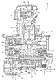
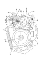
図2を参照して、パワーユニット10のユニットケース13は内燃機関10Eのクランク軸11を軸支するとともに、クランク軸11が配置されるクランク室13Cの後方に変速機10Tを収容するミッション室13Mを構成している。
Referring to FIG. 2, the
ユニットケース13の前側のクランク室13Cの上には、1本のシリンダ14aを有するシリンダブロック14と、シリンダブロック14の上にガスケットを介してシリンダヘッド15が重ねられ、ヘッドボルト17によりシリンダヘッド15,シリンダブロック14がユニットケース13に一体に締結され、シリンダヘッド15の上方をヘッドカバー16が覆っている(図2参照)。
ユニットケース13の前側部分の上に重ねられるシリンダブロック14,シリンダヘッド15およびヘッドカバー20は、クランクケース13から若干前傾した姿勢で上方に延出している(図1参照)。
On the front crank chamber 13C of the
The
シリンダブロック14のシリンダ14a内にピストン18が往復摺動自在に嵌合され(図2参照)、同ピストン18とクランク軸11がコンロッド19により連接されてクランク機構が構成されている。
A
シリンダヘッド15には、図示されない吸排気バルブを駆動する動弁機構20が構成される。
動弁機構20の動弁カム軸21に嵌着された被動カムチェーンスプロケット23とクランク軸11に嵌着された駆動カムチェーンスプロケット22との間にカムチェーン24が架渡され(図2参照)、クランク軸11の1/2の回転数で動弁カム軸21が回転され、吸気ロッカアーム25と排気ロッカアーム26を揺動して吸排気バルブがそれぞれ所要のタイミングで開閉駆動する。
The
A
クランク軸11のユニットケース13の左軸受壁13Lより左方に突出した部分には、前記駆動チェーンスプロケット22とともに一方向クラッチを介してACジェネレータ30のACGロータ30rが嵌合され、ACジェネレータ30等を左側から覆う左ケースカバー27に形成された内筒27aにインナステータ30sが固着支持されている。
他方、クランク軸11のユニットケース13の右軸受壁13Rより右方に突出した部分には、バランサ駆動ギア28とプライマリ駆動ギア29が順次嵌合されている。
An ACG rotor 30r of an
On the other hand, a
ユニットケース13のミッション室13Mには、変速機10Tのメイン軸41とカウンタ軸42とが、クランク軸11の後方に左右方向に指向して互いに平行に左右軸受壁13L,13R間にベアリング41b,42bを介して回転自在に架設されており、メイン軸41に軸支されたメインギア群41gとカウンタ軸42に軸支されたカウンタギア群42gが常時噛み合って変速機10Tを構成している。
In the
図2に示すように、メイン軸41のユニットケース13の右軸受壁13Rより右方に突出した右側部には、多板摩擦式の変速クラッチ35が設けられている。
変速クラッチ35のクラッチアウタ35oは、メイン軸41に回転自在に軸支されたプライマリ被動ギア34に緩衝部材を介して支持されており、メイン軸41に一体に嵌合されたクラッチインナ35iとの間に複数のクラッチ板が介装され、圧縮部材35pの駆動により断接を行う。
As shown in FIG. 2, a multi-plate friction
A clutch outer 35o of the
プライマリ被動ギア34がクランク軸11に嵌着された前記プライマリ駆動ギア29と噛合する。
したがって、クランク軸11の動力を変速クラッチ35の駆動により変速機10Tのメイン軸41に伝達したり遮断したりする。
A primary driven
Therefore, the power of the
カウンタ軸42はユニットケース13の左軸受壁13Lを左方に貫通して外部に突出してパワーユニット10の最終の出力軸42となっており、突出部位に出力スプロケット43がスプライン嵌合されている。
出力スプロケット43に巻き掛けられる駆動チェーン44が、図示されない後輪側の被動スプロケットに架渡されてチェーン伝達機構が構成され後輪に動力が伝達される。
The
A
出力軸(カウンタ軸)42は、ユニットケース13の左軸受壁13Lにベアリング42bを介して軸支されたジャーナル部より左側の左軸受壁13Lより左方に突出した突出部位に、図3ないし図5に示すように、出力スプロケット43が嵌合されるスプライン溝42uuが6条形成されたスプライン部42uと、スプライン溝42uuが出力軸端部に延長された被検知溝42vvが形成された被検知回転部42vが形成されている。
そして、スプライン溝部42uの溝条形成部42v寄りに周方向に外周溝42pが形成されている。
The output shaft (counter shaft) 42 is formed at a protruding portion protruding leftward from the
And the outer peripheral groove |
被検知回転部42vの被検知溝42vvは、スプライン部42uのスプライン溝42uuより溝幅が拡大しているとともに、溝の深さも深く形成されている。
図4(スプライン部42uの断面図)と図5(被検知回転部42vの断面図)とを比較して、被検知溝42vvの溝幅Wvは、スプライン溝42uuの溝幅Wuより大きい。
The detected groove 42vv of the detected
4 (cross-sectional view of the
出力軸(カウンタ軸)42のスプライン部42uに左側から出力スプロケット43がスプライン嵌合され、次いで中空円板状の位置決め部材45がスプライン部42uにスプライン嵌入し、外周溝42pで所定角度回動して軸方向の位置を外周溝42pの左右両側のスプライン突条で規制された状態で、出力スプロケット43と合わせボルト46により一体に締結される。
したがって、出力スプロケット43は位置決め部材45を介して出力軸42の軸方向所定位置に位置決め固定される。
The
Accordingly, the
ユニットケース13の左軸受壁13Lより左方に突出した出力軸42に設けられた出力スプロケット43は、外側カバー部材であるスプロケットカバー50により左側から覆われ、スプロケットカバー50はユニットケース13に取り付けられる。
The
ユニットケース13の左軸受壁13Lにおける出力軸42の軸受周辺は、図7に示すように、軸受円孔13hの周りに後方に開放した略放物線状に湾曲した周壁13rが左方に突出形成されている。
周壁13rの上端近傍と下端に取付孔13ah,13bhを有した取付ボス部13a,13bが外側に膨出形成されており、周壁13rおよび取付ボス部13a,13bの端面は、同一の鉛直平面をなしている。
なお、左軸受壁13Lにおける周壁13rの外側に、上下にそれぞれ位置決め孔13f,13fが形成されている。
As shown in FIG. 7, a
Mounting
In the
一方、出力スプロケット43を覆ってユニットケース13に取り付けられるスプロケットカバー50は、図8および図11を参照して、出力スプロケット43の左側を覆う側壁50sの内面(右側面)に前記ユニットケース13の周壁13rに対応して同じく後方に開放した略放物線状に湾曲した周壁50rが右方に突出形成されている。
周壁50rの端面は、鉛直平面をなしてユニットケース13の周壁13rの端面に対向している。
On the other hand, the
The end surface of the
周壁50rのうち上方を覆う上側周壁50ruには、ユニットケース13の取付孔13ahに対応する取付孔50ahを有した取付ボス部50aが上方(周壁50rの外側)に膨出して形成されており、取付ボス部50aは周壁50rの端面と同一の鉛直端面を有し、同端面の取付孔50ahの前側近傍から位置決め棒50fが前記ユニットケース13の位置決め孔13fに対応して右方に突出形成されている。
また、取付ボス部50aより下方(周壁50rの内側)に一部膨出部が形成され、同膨出部から右方に位置決め突起50gが突出している。
なお、上側周壁50ruの後端部近傍に端面から半円弧状に切り欠かれた切欠き開孔50pが形成されている。
A mounting
Further, a partially bulging portion is formed below the mounting
A
周壁50rのうち下方を覆う下側周壁50rlの後端部は、ユニットケース13の取付孔13bhに対応する取付孔50bhを有した取付ボス部50bが下方(周壁50rの外側)に膨出して形成されており、同取付ボス部50bの端面には取付孔50bhの斜め前方に位置決め突起50gが右方に突出している。
また、下側周壁50rlの前部から下方(周壁50rの外側)へ膨出した部分に位置決め棒50fが前記ユニットケース13の下側の位置決め孔13fに対応して右方に突出形成されている。
The rear end of the lower peripheral wall 50rl that covers the lower part of the
Further, a
そして、スプロケットカバー50の側壁50sの内面における周壁50rに囲まれた中央からユニットケース13の左軸受壁13Lの軸受円孔13hに対応して略同径の外側円筒部51とその内側に出力軸42の被検知回転部42vの外径より若干大きい内径の内側円筒部52とが右方に突出形成されているとともに、外側円筒部51と内側円筒部52の上部を切り欠いて右方にセンサ支持円筒部53が突出している。
Then, an outer
センサ支持円筒部53は、外側円筒部51や内側円筒部52ほどには突出しておらず、外側円筒部51と内側円筒部52のセンサ支持円筒部53より右側部分は、切り欠かれた状態の欠損部51v,52vを形成している。
センサ支持円筒部53の側壁50sとの付け根部分の上側部分も切り欠かれ、この切欠きから側壁50sの内面に互いに平行な前後一対の突条55,55が上方に向かって湾曲しながら延出し、さらに一対の突条55,55は側壁50sから上側周壁50ruの内面(下面)を右方に延長して前記切欠き開孔50pを間に挟む端面まで至っている。
The sensor support
The upper portion of the base portion of the sensor support
スプロケットカバー50の側壁50sにおけるセンサ支持円筒部53より上方部分に、前側の突条55に一部重なってセンサ取付円筒部54が形成されている。
センサ取付円筒部54は側壁50sを貫通している。
スプロケットカバー50の側壁50sにおける後側の突条55に沿って上下にそれぞれ円筒の周りに放射状に複数のリブが形成された取付ボス部56a,56bが突出形成されている。
また、スプロケットカバー50の側壁50sにおけるセンサ取付円筒部54の近傍斜め前方に円筒の周りに放射状に複数のリブが形成された取付ボス部56cが突出形成されている。
A sensor mounting
The sensor mounting
Mounting
In addition, a mounting
このようなスプロケットカバー50の内側に突出したセンサ支持円筒部53とセンサ取付円筒部54の端部に車速センサ70が取り付けられる。
図11および図13を参照して、車速センサ70は、センサ本体71が側面視で略上下に長尺の長円状をして一方の上側円形端部に取付孔71hが形成され、他方の下側円形端部から右方に検出部72を突出し、左方には円筒支持部73が突出しており、同下側円形端部の側面から左方にセンサハーネス75が延出している。
A
Referring to FIGS. 11 and 13, in the
この車速センサ70のセンサ本体71から突出した円筒支持部73をスプロケットカバー50のセンサ支持円筒部53内に嵌合して、センサ本体71の上側にした取付孔71hをセンサ取付円筒部54の孔に一致させて取付ボルト76を内側(右側)から貫通する。
図15に示すように、センサ取付円筒部54にはカラー77を介して外側(左側)からナット部材78が嵌入されており、取付ボルト76はカラー77を貫通してナット部材78に螺合して締結され、車速センサ70がスプロケットカバー50に取り付けられる。
The
As shown in FIG. 15, a
なお、スプロケットカバー50のセンサ取付円筒部54を貫通した円筒ではなくスプロケットカバーに一体形成されたセンサ取付用の単なる円柱ボス部とし、同円柱ボス部に雌ねじを刻設しておいてもよく、車速センサ70のセンサ本体71の取付孔71hを貫通した取付ボルト76が円柱ボス部の雌ねじに螺合して、車速センサ70がスプロケットカバー50に取り付けられる構造としてもよい。
In addition, instead of a cylinder penetrating the sensor mounting
前記したように車速センサ70が取り付けられると、センサ本体71から右方に突出した検出部72は、外側円筒部51の欠損部51vに嵌り、内側円筒部52の欠損部52vに臨む位置に固定される。
すなわち、車速センサ70の検出部72は、内側円筒部52の内側に挿入される出力軸42の左端部分の被検知回転部42vに近接する(図15参照)。
したがって、車速センサ70は検出部72により出力軸42の被検知回転部42vの回転する被検知溝42vvを容易に検知して車速を検出することができる。
As described above, when the
That is, the
Therefore, the
被検知回転部42vの被検知溝42vvは、その溝幅Wvがスプライン部42uのスプライン溝42uuの溝幅Wuより拡大して大きいとともに、溝の深さも深く形成されているので、車速センサ70は回転する被検知溝42vvを確実に検知して車速を精度良く検出することができる。
Since the groove width Wv of the detected groove 42vv of the detected
図11および図12を参照して、センサ本体71の下側円形端部の側面から左方に延出したセンサハーネス75は、スプロケットカバー50のセンサ支持円筒部53の外側を左方に延び、上方に屈曲して側壁50sの内面の前後一対の突条55,55の間を内面に沿って延び、さらに右方に屈曲して上側周壁50ruの内面(下面)の前後一対の突条55,55の間を内面に沿って配線され、上側周壁50ruの端面に半円弧状に切り欠かれた切欠き開孔50pから上方に延出する。
切欠き開孔50pにはグロメット79が介装され、同グロメット79をセンサハーネス75が貫通して上方に出る。
なお、グロメットを介装せずに切欠き開孔50pをセンサハーネス75が直接貫通して上方に出るようにしてもよい。
11 and 12, a
A
Note that the
こうしてスプロケットカバー50の内面に取り付けられる車速センサ70およびセンサハーネス75を、スプロケットカバー50の内面に沿って設けられる内側カバー部材60がスプロケットカバー50の内側から覆う。
スプロケットカバー50と内側カバー部材60とで挟まれた間の収容空間62に、車速センサ70はもとよりセンサハーネス75の一部も収容される。
図9ないし図11を参照して、内側カバー部材60は、概ねセンサカバー部61とセンサカバー部61から延出する通路形成部65が一体に形成されている。
Thus, the
A part of the
Referring to FIGS. 9 to 11, the
センサカバー部61は、スプロケットカバー50の内面に取り付けられる車速センサ70のセンサ本体71の右側を覆う右側壁61sおよび同センサ本体71が取り付けられるセンサ取付円筒部54とセンサ支持円筒部53の周囲を下面を除いて上面と前後面を覆う周壁61rとから概ね構成され、左方は開放されている。
The
なお、センサカバー部61の右側壁61sから右方に円弧状の突出壁61tが突出しており、同突出壁61tはスプロケットカバー50の外側円筒部51の欠損部51vの端縁部を補う位置に形成され、同底壁61tを補強する板状の補強リブ68が突出壁61tの上面と右側壁61sの上部との間に複数突出形成されている(図14参照)。
補強リブ68に補強された突出壁61tおよび右側壁61sの下部により車速センサ70の検出部72が保護される。
Note that an arc-shaped protruding
The
通路形成部65は、スプロケットカバー50の内面に形成された前後一対の突条55,55に外嵌して内部に特にセンサハーネス75を収容する収容空間62を構成する左方を開放した断面コ字状をなして、センサカバー部61のスプロケットカバー50寄り左側部分から上方に延設されている。
The
なお、通路形成部65のセンサカバー部61から延出する付け根部分に板状の補強リブ69が複数平行に突出形成されており、複数の補強リブ69によりセンサカバー部61に対して長尺に延びる通路形成部65を補強支持する。
A plurality of plate-like reinforcing
通路形成部65は、スプロケットカバー50の前後一対の突条55,55に沿ってセンサカバー部61から上方に延出したのち、さらに突条55,55に沿って側壁50sから上側周壁50ruの内面(下面)を右方に延長し、切欠き開孔50pを間に挟む端面を若干越えたところで通路を閉塞するように鉛直の押さえ壁65aが形成されている。
The
内側カバー部材60は、センサカバー部61の周壁61rの前側周壁に膨出して取付有底円筒部66cが形成されるとともに、通路形成部65の後側側壁の上下2箇所に膨出して有底取付円筒部66a,66bがそれぞれ形成されている。
3つの取付有底円筒部66a,66b,66cは、前記スプロケットカバー50の放射状にリブが形成された3つの取付ボス部56a,56b,56cにそれぞれ対応している。
各取付有底円筒部66a,66b,66cは、左方に開口して右側に中空の底壁を有して、対応する取付ボス部56a,56b,56cの放射状リブに被せられ、取付ボス部56a,56b,56cの各円筒部先端に嵌合する円孔66ah,66bh,66chが各底壁に穿設されている。
The
The three bottomed
Each mounting bottomed
したがって、図11および図12を参照して、スプロケットカバー50の内側に、前記したように車速センサ70が取付ボルト76により取り付けられ、車速センサ70から延出したセンサハーネス75がスプロケットカバー50の側壁50sおよび上側周壁50ruの内面に形成された前後一対の突条55,55の間に配線され、センサハーネス75の貫通したグロメット79が切欠き開孔50pに介装された状態で、内側カバー部材60が車速センサ70とセンサハーネス75に内側(右側)から被せられる。
11 and 12, the
内側カバー部材60のセンサカバー部61が車速センサ70を覆い、内側カバー部材60の通路形成部65が突条55,55に外嵌してセンサハーネス75をスプロケットカバー50の内面に沿って覆い、スプロケットカバー50の3つの取付ボス部56a,56b,56cにそれぞれ取付有底円筒部66a,66b,66cが被せられる。
The
図16には、取付ボス部56aと取付有底円筒部66aの嵌合状態を断面図で示しており、同図16に示すように、取付ボス部56aの円筒部の放射状リブより先端が若干突出した突出部56pに、取付有底円筒部66aの底壁の円孔66ahが嵌合する。
他の2つの取付ボス部56bと取付有底円筒部66bの嵌合および取付ボス部56cと取付有底円筒部66cの嵌合も同様である。
この3箇所の取付ボス部56a,56b,56cの各円筒部の突出部56p,56p,56pと取付有底円筒部66a,66b,66cの底壁の円孔66ah,66bh,66chの嵌合により、スプロケットカバー50に対して内側カバー部材60が位置決めされて取り付けられる。
FIG. 16 is a cross-sectional view showing the fitting state of the mounting
The same applies to the fitting of the other two mounting
By fitting the
そして、取付ボス部56a,56b,56cの円筒部先端が取付有底円筒部66a,66b,66cの円孔66ah,66bh,66chに嵌合して露出した各取付ボス部56a,56b,56cの円孔に、それぞれ座金付きタッピングねじ67がねじ立てをしながらねじ込まれて、内側カバー部材60がスプロケットカバー50の内側に取り付けられる(図12,図13,図14,図16参照)。
なお、内側カバー部材60の通路形成部65の端部の鉛直の押さえ壁65aは、切欠き開孔50pに介装されたグロメット79を右側から押さえ付けている。
The cylindrical bosses of the mounting
The vertical
こうして、スプロケットカバー50の内側に車速センサ70および内側カバー部材60を取り付けた後に、図13に示すように、スプロケットカバー50の略放物線状に湾曲した周壁50rの端面に、略同様に後方を開放した放物線状に湾曲した板状のチェーンガイド部材80を当接する。
Thus, after the
チェーンガイド部材80は、湾曲した内側曲面80cがスプロケットカバー50の内側円筒部52の中心軸(出力軸42の中心軸)を中心にした円弧面をなし、上端部近傍に外側に膨出した取付部80aが取付孔80ahを有して設けられ、その近傍に位置決め孔80gが形成されている。
また、チェーンガイド部材80の下端部には、下方に屈曲した取付部80bが取付孔80bhを有して設けられ、その近傍に位置決め孔80gが形成されている。
The
Further, an
したがって、チェーンガイド部材80は、上下の位置決め孔80g,80gにスプロケットカバー50の位置決め突起50g,50gをそれぞれ嵌合して位置決めされて、周壁50rの端面に当接される。
すると、チェーンガイド部材80の取付部80a,80bが、スプロケットカバー50の取付ボス部50a,50bに当接して、両者の取付孔80ahと取付孔50ah、取付孔80bhと取付孔50bhを一致させる(図13参照)。
Therefore, the
Then, the mounting
このように、スプロケットカバー50の周壁50rの端面にチェーンガイド部材80を位置決めして当接した状態で、スプロケットカバー50をユニットケース13の左軸受壁13Lに出力スプロケット43を覆うように被せる。
In this manner, the
このとき、スプロケットカバー50の左側に突出する上下の位置決め棒50f,50fの先端を、ユニットケース13の位置決め孔13f,13fに嵌入することで、スプロケットカバー50をユニットケース13に対して位置決めすると、スプロケットカバー50の取付孔50ah,50bh(チェーンガイド部材80の取付孔80ah,80bh)がユニットケース13の取付孔13ah,13bhと一致するので、一致した取付孔50ah,80ah,13ahおよび取付孔50bh,80bh,13bhに左外側から締結ボルト81,81を螺入して締結し、スプロケットカバー50をユニットケース13にチェーンガイド部材80を共締め介装して取り付ける。
At this time, when the
出力軸42にスプライン嵌合された出力スプロケット43に駆動チェーン44が巻き掛けられるが、この出力スプロケット43に巻き掛けられた駆動チェーン44の外周囲にチェーンガイド部材80の内側曲面80cが近接して配置されることで、駆動チェーン44をガイドして支障なく安定した動力伝達を確保している。
The
図14および図15に示すように、スプロケットカバー50と内側カバー部材60との間の収容空間62は、車速センサ70の左側がスプロケットカバー50の側壁50s、右側が内側カバー部材60のセンサカバー部61の側壁61s、前後および上側がセンサカバー部61の周壁61rにより覆われ、下側はスプロケットカバー50のセンサ支持円筒部53および外側円筒部51、内側円筒部52により覆われているが、出力軸42の被検知回転部42vが挿入される内側円筒部52の欠損部52vが唯一下方に開放されていて、同欠損部52vに車速センサ70の検出部72が臨んで被検知回転部42vの回転する被検知溝42vvを確実に検知するようにしている。
As shown in FIGS. 14 and 15, the accommodation space 62 between the
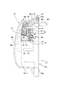
スプロケットカバー50と内側カバー部材60との間の収容空間62に収容されたセンサハーネス75は、スプロケットカバー50の上側周壁50ruの端面の切欠き開孔50pに介装されたグロメット79から外部上方に延出しているので、図1に示すように、側面視でセンサハーネス75が目立つようなことはなく、良好な外観性を保つことができる。
The
図1を参照して、ヘッドパイプ2hの前方にスピードメータ90等のメータ類が取り付けられており、同メータ類から延出するメータハーネス91がヘッドパイプ2hからメインフレーム2mに沿って後方に延びている。
一方、前記したように、スプロケットカバー50の上側周壁50ruからセンサハーネス75が上方に延出しており、同センサハーネス75はメインフレーム2mの急傾斜部2maに沿って上方に延び、メインフレーム2mの屈曲部辺りで前記メータハーネス91と一緒になってシートレール2sに沿って後方に向かい、シートレール2s上のバックステー2bとの接続部より若干後側に搭載されたECU95に接続されている。
左右のメインフレーム2m,2mの急傾斜部2ma,2maの間には、ユニットケース13の上にバッテリ94が搭載されており、バッテリ94からもECU95にハーネスが延びている。
Referring to FIG. 1, meters such as a
On the other hand, as described above, the
A
このように、スプロケットカバー50内に配設された車速センサ70から延出するセンサハーネス75は、スプロケットカバー50の上側周壁50ruの切欠き開孔50pから上方に延出しているので、パワーユニット10より上方のシートレール2s上のECU95へのセンサハーネス75の取り回しが容易で、ハーネスの長さを短く設定することができる。
Thus, since the
上記したように、スプロケットカバー50内において、スプロケットカバー50の内側に設けられる内側カバー部材60が、スプロケットカバー50との間に形成される収容空間62に車速センサ70と同車速センサ70から延出するセンサハーネス75の一部を収容するので、スプロケットカバー50に覆われる出力スプロケット43による動力伝達機構の存在する空間から内側カバー部材60が車速センサ70やセンサハーネス75の収容される収容空間62を仕切って、出力スプロケット43や駆動チェーン45の回動により飛散する異物が収容空間62に侵入するのを阻止しているため、車速センサ70の検出部72と被検知回転部材42vの間に異物が侵入して速度検出を妨げるようなことはなく、車速センサ70の検出性能の低下を防止することができる。
As described above, in the
センサハーネス75は、スプロケットカバー50の側壁50sと上側周壁50ruの内面に沿って配設されるので、センサハーネス75を弛ませることなく纏まりよく配設し内側カバー部材60もスプロケットカバー50の内面に沿わせることで、出力スプロケット43による動力伝達機構に干渉させずにスプロケットカバー50を極力小型化することができる。
Since the
スプロケットカバー50の内面にセンサハーネス75を間にして両側に互いに平行な一対の突条55,55が突出形成され、内側カバー部材60は、一対の突条55,55に外嵌して内部に前記収容空間62を構成する断面コ字状の通路形成部65を備えているので、スプロケットカバー50の一対の突条55,55に内側カバー部材60の通路形成部65が外嵌することで、外嵌される部分は突条55と内側カバー部材60の側壁との重なりによりラビリンス構造を構成し、異物が車速センサ70の収容空間62内に侵入するのを極力防止することができる。
A pair of
車速センサ70は、出力軸42に一体に形成される被検知回転部42vの被検知溝42vvを検知するので、被検知回転部材専用の部品を必要とせず部品点数を削減し組付作業を簡単にしてコストの低減を図ることができる。
Since the
出力スプロケット43は、後輪Rw側へ動力を伝達する駆動チェーン44が巻き掛けられる出力スプロケット43であり、出力軸42に形成されたスプライン部42uにスプライン嵌合し、同スプライン部42uのスプライン溝42uuの出力軸端部に延長された被検知溝42vvが形成された部位が被検知回転部42vであるので、スプライン溝42uuと同時に被検知溝42vvを加工形成することができ、加工コストを抑えることができる。
The
1…自動二輪車、10…パワーユニット、10E…内燃機関、10T…変速機、11…クランク軸、12…出力軸、13…ユニットケース、13L…左軸受壁、13r…周壁、13a,13b…取付ボス部、
42…出力軸(カウンタ軸)、42u…スプライン部、42v…被検知回転部(被検知回転部材)、43…出力スプロケット、44…駆動チェーン、45…位置決め部材、
50…スプロケットカバー、50s…側壁、50r…周壁、50p…切欠き開孔、50a,50b…取付ボス部、51…外側円筒部、52…内側円筒部、53…センサ支持円筒部、54…センサ取付円筒部、55…突条、56…取付ボス部、
60…内側カバー部材、61…センサカバー部、61s…側壁、61r…周壁、62…収容空間、65…通路形成部、66…取付有底円筒部、67…座金付きタッピングねじ、
70…車速センサ、71…センサ本体、72…検出部、73…円筒支持部、75…センサハーネス、76…取付ボルト、78…ナット部材、79…グロメット、
80…チェーンガイド部材、81…締結ボルト、90…スピードメータ、91…メータハーネス、94…バッテリ、95…ECU。
DESCRIPTION OF
42 ... Output shaft (counter shaft), 42u ... Spline portion, 42v ... Detected rotating portion (detected rotating member), 43 ... Output sprocket, 44 ... Drive chain, 45 ... Positioning member,
50 ... Sprocket cover, 50s ... Side wall, 50r ... Peripheral wall, 50p ... Notch opening, 50a, 50b ... Mounting boss part, 51 ... Outer cylindrical part, 52 ... Inner cylindrical part, 53 ... Sensor support cylindrical part, 54 ... Sensor Mounting cylindrical part, 55 ... Projection, 56 ... Mounting boss part,
60 ... inner cover member, 61 ... sensor cover part, 61s ... side wall, 61r ... peripheral wall, 62 ... accommodation space, 65 ... passage forming part, 66 ... cylindrical part with mounting, 67 ... tapping screw with washer,
70 ... Vehicle speed sensor, 71 ... Sensor body, 72 ... Detection part, 73 ... Cylindrical support part, 75 ... Sensor harness, 76 ... Mounting bolt, 78 ... Nut member, 79 ... Grommet,
80 ... chain guide member, 81 ... fastening bolt, 90 ... speedometer, 91 ... meter harness, 94 ... battery, 95 ... ECU.
Claims (8)
前記出力軸(42)の突出部位の前記駆動回転部材(43)より外側部位に被検知回転部材(42v)が一体に設けられ、
車速センサ(70)が前記被検知回転部材(42v)に検出部(72)を近接させて前記外側カバー部材(50)の内側に支持され、
前記車速センサ(70)から延出するセンサハーネス(75)の前記外側カバー部材(50)の内側に配設される部分は、前記外側カバー部材(50)の内面に沿って設けられる内側カバー部材(60)によって内側から覆われることを特徴とする車載パワーユニットの車速センサハーネスのカバー構造。 The final output shaft (42) of the power unit (10) protrudes outward from the unit case (13), and the drive rotating member (43) is fitted to the protruding portion of the output shaft (42). (43) is covered from the outside by the outer cover member (50) together with the projecting portion of the output shaft (42), and the power is transmitted from the drive rotating member (43) to the rear rear wheel to drive the motorcycle. In the power unit,
A detected rotation member (42v) is provided integrally with a portion outside the drive rotation member (43) of the projecting portion of the output shaft (42),
A vehicle speed sensor (70) is supported on the inner side of the outer cover member (50) by bringing the detection portion (72) close to the detected rotation member (42v),
The portion of the sensor harness (75) that extends from the vehicle speed sensor (70) is disposed on the inner side of the outer cover member (50), and the inner cover member is provided along the inner surface of the outer cover member (50). (60) A vehicle speed sensor harness cover structure for an in-vehicle power unit, which is covered from the inside by (60).
前記センサハーネス(75)は、前記外側カバー部材(50)の前記周壁(50r)に形成された開孔(50p)から外部に延出することを特徴とする請求項1記載の車載パワーユニットの車速センサハーネスのカバー構造。 The outer cover member (50) includes a side wall (50s) substantially perpendicular to the output shaft (42) and a peripheral wall (50r) covering the periphery excluding the rear of the drive rotation member (43),
The vehicle speed of the in-vehicle power unit according to claim 1, wherein the sensor harness (75) extends outside from an opening (50p) formed in the peripheral wall (50r) of the outer cover member (50). Sensor harness cover structure.
前記内側カバー部材(60)は、前記一対の突条(55,55)に外嵌して内部に収容空間(62)を構成する断面コ字状の通路形成部(65)を備えたことを特徴とする請求項1ないし請求項4のいずれの項記載の車載パワーユニットの車速センサハーネスのカバー構造。 A pair of protrusions (55, 55) parallel to each other on both sides with the sensor harness (75) in between on the inner surface of the outer cover member (50),
The inner cover member (60), it having the U-shaped cross section of the passage forming portion constituting the yield capacity space (62) therein and fitted in a pair of ridges (55, 55) (65) The cover structure of the vehicle speed sensor harness of the vehicle-mounted power unit according to any one of claims 1 to 4, wherein
前記出力軸(42)に形成されたスプライン部(42u)に前記出力スプロケット(43)はスプライン嵌合し、
前記スプライン部(42u)のスプライン溝(42uu)の出力軸端部に延長された被検知溝(42vv)が形成された部位が前記被検知回転部(42v)であることを特徴とする請求項6記載の車載パワーユニットの車速センサハーネスのカバー構造。 The drive rotating member (43) is an output sprocket (43) around which a drive chain (44) for transmitting power to the rear wheel side is wound,
The output sprocket (43) is spline-fitted to a spline portion (42u) formed on the output shaft (42),
The portion where the detected groove (42vv) extended at the output shaft end portion of the spline groove (42uu) of the spline portion (42u) is the detected rotating portion (42v). The cover structure of the vehicle speed sensor harness of the vehicle-mounted power unit according to claim 6.
Priority Applications (2)
| Application Number | Priority Date | Filing Date | Title |
|---|---|---|---|
| JP2010278950A JP5324552B2 (en) | 2010-12-15 | 2010-12-15 | Cover structure of vehicle speed sensor harness for in-vehicle power unit |
| BRPI1106898 BRPI1106898A2 (en) | 2010-12-15 | 2011-12-13 | onboard power unit vehicle speed sensor harness cover structure |
Applications Claiming Priority (1)
| Application Number | Priority Date | Filing Date | Title |
|---|---|---|---|
| JP2010278950A JP5324552B2 (en) | 2010-12-15 | 2010-12-15 | Cover structure of vehicle speed sensor harness for in-vehicle power unit |
Publications (2)
| Publication Number | Publication Date |
|---|---|
| JP2012126235A JP2012126235A (en) | 2012-07-05 |
| JP5324552B2 true JP5324552B2 (en) | 2013-10-23 |
Family
ID=46643790
Family Applications (1)
| Application Number | Title | Priority Date | Filing Date |
|---|---|---|---|
| JP2010278950A Expired - Fee Related JP5324552B2 (en) | 2010-12-15 | 2010-12-15 | Cover structure of vehicle speed sensor harness for in-vehicle power unit |
Country Status (2)
| Country | Link |
|---|---|
| JP (1) | JP5324552B2 (en) |
| BR (1) | BRPI1106898A2 (en) |
Families Citing this family (1)
| Publication number | Priority date | Publication date | Assignee | Title |
|---|---|---|---|---|
| JP7431792B2 (en) * | 2021-12-08 | 2024-02-15 | 本田技研工業株式会社 | saddle type vehicle |
Family Cites Families (4)
| Publication number | Priority date | Publication date | Assignee | Title |
|---|---|---|---|---|
| JP2514943Y2 (en) * | 1987-03-18 | 1996-10-23 | アイシン精機株式会社 | Transmission with rotation sensor |
| JP3058671B2 (en) * | 1990-10-29 | 2000-07-04 | 森山工業株式会社 | Vehicle speed detector |
| JPH0529894U (en) * | 1991-09-30 | 1993-04-20 | 本田技研工業株式会社 | Chain guide mounting structure for power take-off device for small vehicles |
| JP3042352B2 (en) * | 1995-03-20 | 2000-05-15 | スズキ株式会社 | Vehicle speed detection device for small vehicles |
-
2010
- 2010-12-15 JP JP2010278950A patent/JP5324552B2/en not_active Expired - Fee Related
-
2011
- 2011-12-13 BR BRPI1106898 patent/BRPI1106898A2/en active Search and Examination
Also Published As
| Publication number | Publication date |
|---|---|
| JP2012126235A (en) | 2012-07-05 |
| BRPI1106898A2 (en) | 2013-04-16 |
Similar Documents
| Publication | Publication Date | Title |
|---|---|---|
| JP5546302B2 (en) | Vehicle speed sensor mounting structure | |
| JP5250522B2 (en) | Hybrid vehicle | |
| JP2010281223A (en) | Oil breather device for motorcycle engines | |
| JP2011073627A (en) | Hybrid type motorcycle | |
| JP2015010475A (en) | Cover structure of an internal combustion engine for a motorcycle | |
| JP5208786B2 (en) | Horizontal engine | |
| JP5473133B2 (en) | Ignition system for saddle-ride type vehicles | |
| KR101157363B1 (en) | Crank case structure of internal combustion engine | |
| JP2019206955A (en) | Suction structure of saddle-ride type vehicle | |
| JP5324552B2 (en) | Cover structure of vehicle speed sensor harness for in-vehicle power unit | |
| JP2002037174A (en) | Engine exhaust device support structure for motorcycles | |
| JP5951431B2 (en) | Mounting structure of a vehicle speed sensor in a motorcycle | |
| JP6781347B2 (en) | Internal combustion engine | |
| CN112664293B (en) | Internal combustion engines for saddle-riding vehicles | |
| JP2000233782A (en) | Air intake structure for small vehicles | |
| JP2009024555A (en) | Breather device for internal combustion engine | |
| JP2012136996A (en) | Crank angle detection device for internal combustion engine | |
| JP2009214813A (en) | Motorcycle | |
| JP2012136997A (en) | Crank angle detection device for internal combustion engine | |
| JP7383675B2 (en) | ACG cover for internal combustion engine | |
| JP2009085096A (en) | Starter motor peripheral structure | |
| JP6963116B2 (en) | Cover structure of power unit of saddle type vehicle | |
| JP6843734B2 (en) | Motorcycle transmission | |
| JP6256068B2 (en) | Gear support structure for cam gear train mechanism of motorcycle | |
| JPH0270927A (en) | Unit swing type engine |
Legal Events
| Date | Code | Title | Description |
|---|---|---|---|
| A621 | Written request for application examination |
Free format text: JAPANESE INTERMEDIATE CODE: A621 Effective date: 20121127 |
|
| A131 | Notification of reasons for refusal |
Free format text: JAPANESE INTERMEDIATE CODE: A131 Effective date: 20130423 |
|
| A977 | Report on retrieval |
Free format text: JAPANESE INTERMEDIATE CODE: A971007 Effective date: 20130425 |
|
| A521 | Written amendment |
Free format text: JAPANESE INTERMEDIATE CODE: A523 Effective date: 20130520 |
|
| TRDD | Decision of grant or rejection written | ||
| A01 | Written decision to grant a patent or to grant a registration (utility model) |
Free format text: JAPANESE INTERMEDIATE CODE: A01 Effective date: 20130709 |
|
| A61 | First payment of annual fees (during grant procedure) |
Free format text: JAPANESE INTERMEDIATE CODE: A61 Effective date: 20130718 |
|
| R150 | Certificate of patent or registration of utility model |
Ref document number: 5324552 Country of ref document: JP Free format text: JAPANESE INTERMEDIATE CODE: R150 Free format text: JAPANESE INTERMEDIATE CODE: R150 |
|
| LAPS | Cancellation because of no payment of annual fees |