JP2012136996A - Crank angle detection device for internal combustion engine - Google Patents
Crank angle detection device for internal combustion engine Download PDFInfo
- Publication number
- JP2012136996A JP2012136996A JP2010289310A JP2010289310A JP2012136996A JP 2012136996 A JP2012136996 A JP 2012136996A JP 2010289310 A JP2010289310 A JP 2010289310A JP 2010289310 A JP2010289310 A JP 2010289310A JP 2012136996 A JP2012136996 A JP 2012136996A
- Authority
- JP
- Japan
- Prior art keywords
- crank angle
- gear
- internal combustion
- combustion engine
- crankshaft
- Prior art date
- Legal status (The legal status is an assumption and is not a legal conclusion. Google has not performed a legal analysis and makes no representation as to the accuracy of the status listed.)
- Pending
Links
Images


Abstract
Description
本発明は、内燃機関のクランク角を検出する内燃機関用クランク角検出装置に関する。 The present invention relates to a crank angle detection device for an internal combustion engine that detects a crank angle of the internal combustion engine.
図5に示すように、内燃機関(エンジン)用のクランク角検出装置100は、従来、クランク軸101の軸端に取り付けられたセンシングロータ102の外周における突起または窪みをクランク角センサ103が検知することで、クランク軸101の回転角、つまりクランク角を検出するよう構成されている。
As shown in FIG. 5, in the crank
前記クランク角センサ103は、クランクケース104の側部で、エンジンサイドカバー105の内側に設置されている。尚、クランク軸101の回転力は、クランク軸101に設けられたプライマリドライブギア108を経てプライマリドリブンギア109に伝達される。
The
また、特許文献1には、クランク軸のクランクウェイトに、クランク角検出用の歯が外周に形成された弓形セグメントを取り付け、クランク軸の回転時に、クランク角センサにより弓形セグメントの歯を検出することで、クランク軸の回転角(クランク角)を検出するクランク角検出装置が開示されている。 Further, in Patent Document 1, an arcuate segment in which teeth for crank angle detection are formed on the outer periphery is attached to the crankweight of the crankshaft, and the teeth of the arcuate segment are detected by the crank angle sensor when the crankshaft rotates. Thus, a crank angle detection device for detecting the rotation angle (crank angle) of the crankshaft is disclosed.
ところが、図5に示すクランク角検出装置100では、クランク軸101の軸端にセンシングロータ102を取り付ける構成であるため、エンジンの軸方向長さが増大して、エンジンの小型化及び軽量化が困難になってしまうと共に、クランク軸101やクランクケース104の剛性確保も困難になってしまう。
However, in the crank
また、センシングロータ102は、ワッシャ106や取付ボルト107を用いてクランク軸101に取り付けられるため、部品点数が増加し、組付工数も増加してしまう。
Moreover, since the
更に、クランク軸101にセンシングロータ102を取り付ける為の隙間分のガタツキによって、クランク角センサ103によるクランク角の検出精度が低下してしまう。
Furthermore, the accuracy of crank angle detection by the
また、自動二輪車に搭載されたエンジンの場合には、車両のバンク角を確保するために、センシングロータ102の外径を大きくすることができない。従って、センシングロータ102の外周の突起または窪みの周速度が低くなるので、特にクランク軸101の低速回転時にはクランク角センサ103によりクランク角を高精度に検出することができない恐れがある。
In the case of an engine mounted on a motorcycle, the outer diameter of the
他方、特許文献1に記載のクランク角検出装置では、クランク軸には、動力伝達用のプライマリドライブギアやカムドライブスプロケットなどのほかに、クランク角検出用のギア(弓形セグメント)が必要になるので、部品点数及び組付工数が増加してしまう。 On the other hand, in the crank angle detection device described in Patent Document 1, a crank angle detection gear (bow segment) is required on the crankshaft in addition to the primary drive gear for power transmission and the cam drive sprocket. The number of parts and assembly man-hours will increase.
本発明の目的は、上述の事情を考慮してなされたものであり、内燃機関の幅方向長さを短縮して内燃機関の小型化及び軽量化を実現できると共に、部品点数及び組付工数を低減できる内燃機関用クランク角検出装置を提供することにある。 The object of the present invention has been made in consideration of the above-mentioned circumstances, and it is possible to reduce the length in the width direction of the internal combustion engine to reduce the size and weight of the internal combustion engine, and to reduce the number of parts and assembly man-hours. An object of the present invention is to provide a crank angle detection device for an internal combustion engine that can be reduced.
本発明は、内燃機関に備えられたクランク軸と、このクランク軸の回転角をクランク角として検出するクランク角センサと、を有する内燃機関用クランク角検出装置において、前記クランク軸の一部に第1のギアが回転一体に設けられ、この第1のギアは、隣接する第2のギアに動力を伝達すると共に、高低差を有する段差部を備え、前記クランク角センサは、前記段差部を基準として前記第1のギアを検知することで前記クランク角を検出可能に構成されたことを特徴とするものである。 The present invention provides a crank angle detection device for an internal combustion engine having a crank shaft provided in an internal combustion engine and a crank angle sensor that detects a rotation angle of the crank shaft as a crank angle. The first gear is provided integrally with the rotation, and the first gear transmits power to the adjacent second gear and has a step portion having a height difference. The crank angle sensor is based on the step portion. As described above, the crank angle can be detected by detecting the first gear.
本発明によれば、クランク軸の一部に回転一体に設けられた第1のギアに段差部が設けられ、クランク角センサが、前記段差部を基準として第1のギアを検知することでクランク角を検出するので、クランク角検出用のセンシングロータをクランク軸の端部に設ける必要がない。この結果、内燃機関の幅方向長さが短縮して内燃機関の小型化及び軽量化を実現できる。更に、センシングロータが不要になるので、部品点数及び組付工数を低減できる。 According to the present invention, a step portion is provided in the first gear that is provided integrally with a part of the crankshaft, and the crank angle sensor detects the first gear on the basis of the step portion. Since the angle is detected, there is no need to provide a sensing rotor for detecting the crank angle at the end of the crankshaft. As a result, the length of the internal combustion engine in the width direction is shortened, and the internal combustion engine can be reduced in size and weight. Furthermore, since a sensing rotor is not required, the number of parts and the number of assembly steps can be reduced.
以下、本発明を実施するための実施形態を図面に基づき説明する。但し、本発明は、これらの実施の形態に限定されるものではない。 DESCRIPTION OF EMBODIMENTS Hereinafter, embodiments for carrying out the present invention will be described with reference to the drawings. However, the present invention is not limited to these embodiments.
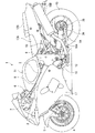
図1は、本発明に係る内燃機関用クランク角検出装置の一実施形態が適用された内燃機関としてのエンジンを搭載する自動二輪車を示す左側面図である。尚、本実施形態において、前後、上下、左右の表現は、自動二輪車に乗車した乗員を基準にしたものである。 FIG. 1 is a left side view showing a motorcycle equipped with an engine as an internal combustion engine to which an embodiment of a crank angle detection device for an internal combustion engine according to the present invention is applied. In the present embodiment, expressions of front and rear, top and bottom, and left and right are based on a passenger who rides the motorcycle.
この図1に示すように、自動二輪車1は車体フレーム2を有し、その前方にヘッドパイプ3が設けられる。ヘッドパイプ3には、図示しないサスペンション機構を内装し前輪4を回動自在に支持する左右一対のフロントフォーク5やハンドルバー6等から構成されるステアリング機構7が設けられ、ハンドルバー6により前輪4が左右に回動自在に操舵される。
As shown in FIG. 1, a motorcycle 1 has a body frame 2, and a head pipe 3 is provided in front thereof. The head pipe 3 is provided with a steering mechanism 7 including a pair of left and
一方、車体フレーム2は、例えばツインチューブ型のもので、ヘッドパイプ3の直後で左右方向に拡開された後、互いに平行に後斜下方に延びる左右一対のタンクレールを兼ねたメインフレーム8と、これらのメインフレーム8の後端部に接続され、略上下方へ向かって延びる左右一対のセンタフレーム9と、これらのセンタフレーム9の後上端から後方に延びる左右一対のシートレール10とを有して構成される。
On the other hand, the vehicle body frame 2 is, for example, of a twin tube type, and is expanded to the left and right immediately after the head pipe 3 and then serves as a
メインフレーム8の上方には燃料タンク11が配置され、シートレール10の上方にはライダシート12A、ピリオンシート12Bが車両の前後にそれぞれ配置される。また、センタフレーム9の略中央下部にはピボット軸13が架設され、このピボット軸13にスイングアーム14がピボット軸13廻りにスイング自在に枢着されると共に、このスイングアーム14の後端に後輪15が回動自在に軸支される。そして、前輪4と後輪15間の車体中央下部で燃料タンク11下方に、内燃機関としてのエンジン16が配置される。
A
更に、この自動二輪車1は車体の前部が流線形のカウリング17で覆われており、走行中の空気抵抗低減と、走行風圧からのライダの保護が図られている。尚、図1中の符号18Aは、エンジン16からの排気ガスを排出するエキゾーストパイプであり、このエキゾーストパイプ18Aの後端に排気マフラ18Bが接続されている。
Further, in the motorcycle 1, the front portion of the vehicle body is covered with a
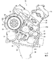
図2及び図3に示すように、エンジン16は4サイクル多気筒エンジン、例えば4サイクル並列4気筒エンジンであり、主にヘッドカバー19、シリンダヘッド20、シリンダブロック21及びクランクケース22から外形が構成される。このクランクケース22は分割式であり、例えば図2における上下方向に2分割され、シリンダブロック21が別体に設けられたアッパクランクケース22Aと、ロアクランクケース22Bとから構成される。ロアクランクケース22Bの下部にオイルパン28が設置されている。
As shown in FIGS. 2 and 3, the
シリンダブロック21は直立よりやや前傾して配置され、また、アッパクランクケース22Aとロアクランクケース22Bとの合わせ面23の内側に軸受部24がそれぞれ上下に分割して形成される。これらの軸受部24に、エンジン16の幅方向に延びるクランク軸25が回転自在に支持される。
The
クランク軸25には、コンロッド26の大端部26Aが連結され、図4に示すように、コンロッド26の小端部26Bにはピストン27が連結される。そして、シリンダブロック21内にはピストン27が、図における略上下方向に摺動自在に収納される。また、シリンダヘッド20とピストン27との間の空間には燃焼室(不図示)が形成される。この燃焼室内での混合気の燃焼によってピストン27が往復運動し、このピストン27の往復運動がクランク軸25により回転運動に変換される。
A
図2に示すように、クランクケース22内には、クランク軸25の後方にカウンタ軸29及びドライブ軸30が、クランク軸25の前方にバランサ軸31がそれぞれ配置される。このうち、カウンタ軸29とバランサ軸31がクランク軸25と共に、アッパクランクケース22Aとロアクランクケース22Bとの合せ面23に軸支されている。これらのクランク軸25、カウンタ軸29、ドライブ軸30及びバランサ軸31は、エンジン16の幅方向(つまり自動二輪車1の車幅方向)に延在してクランクケース22内に収容されている。
As shown in FIG. 2, in the
クランク軸25には、後に詳説するようにプライマリドライブギア32が回転一体に設けられ、このプライマリドライブギア32が、カウンタ軸29に回転自在に軸支されたプライマリドリブンギア33に噛み合う。カウンタ軸29には、プライマリドリブンギア33に連結されたクラッチ機構34が軸端に設けられると共に、図示しない複数段のミッションドライブギアが軸装される。これらのミッションドライブギアは、ドライブ軸30に軸装された図示しない複数段のミッションドリブンギアに噛み合う。これらのミッションドライブギア及びミッションドリブンギアは、図示しないシフト機構と共に変速ミッション機構を構成する。
As will be described in detail later, the
ドライブ軸30の軸端はクランクケース22の外部に突出し、このドライブ軸30の軸端にドライブスプロケット(不図示)が固定される。また、後輪15には、図1に示すようにドリブンスプロケット35が固定され、これらのドライブスプロケットとドリブンスプロケット35との間にドライブチェーン36が巻き掛けられる。
The shaft end of the
従って、図1及び図2に示すエンジン16のクランク軸25の回転力(つまりエンジン16の駆動力)は、プライマリドライブギア32、プライマリドリブンギア33及びクラッチ機構34を経てカウンタ軸29に伝達され、このカウンタ軸29から変速ミッション機構を経てドライブ軸30へ伝達される。そして、このドライブ軸30に伝達されたクランク軸25の回転力は、ドライブスプロケット、ドライブチェーン36及びドリブンスプロケット35を経て後輪15に伝達される。
Therefore, the rotational force of the
また、バランサ軸31には、バランサドリブンギア37が回転一体に設けられると共に、図示しないバランサウェイトが配置される。バランサドリブンギア37は、バランサドライブギアとしても機能するプライマリドライブギア32に噛み合う。従って、クランク軸25の回転によりプライマリドライブギア32及びバランサドリブンギア37を介してバランサウェイトが回転し、クランク軸25に設けられたクランクウェイト38(図3)と共に、ピストン27の往復運動に伴うエンジン16の振動が低減される。
In addition, a balancer driven
ところで、クランク軸25に回転一体に設けられた第1のギアとしての前記プライマリドライブギア32は、図3及び図4に示すように、クランクウェイト38に設けられる。このプライマリドライブギア32は、クランクウェイト38を直接歯切り加工して形成されてもよく、または別途加工されたギアを圧入などによりクランクウェイト38に結合することで形成されてもよい。このプライマリドライブギア32が、前述の如く、第2のギアとしての隣接するプライマリドリブンギア33とバランサドリブンギア37に噛み合い、クランク軸25の回転力をカウンタ軸29とバランサ軸31にそれぞれ伝達する。
By the way, the
ここで、プライマリドライブギア32が設けられるクランクウェイト38は、クランク軸25における一端側(例えば車両右端側)に設けられた一対のクランクウェイト38A及び38Bのうち、エンジン16の中心側に位置するクランクウェイト38Aである。
Here, the crank
後述の如く、プライマリドライブギア32をセンシング(検知)するクランク角センサ41に接続される図示しないケーブルの配索を考慮した場合、プライマリドライブギア32の位置はエンジン16の外側に近い位置であることが望ましい。しかし、クランクウェイト38は、クランク軸25の両端に設置することがエンジン16の振動抑制の観点から効果的であるため、クランクウェイト38Aとクランクウェイト38Bのうち、クランク軸25の最端に位置するクランクウェイト38Bは、本来のクランクウェイトとしたい。これらのことから、プライマリドライブギア32が設けられる位置を上述のクランクウェイト38Aとしたのである。
As will be described later, when the cable not shown connected to the
さて、本実施形態のエンジン16は、内燃機関用のクランク角検出装置40を備える。このクランク角検出装置40は、クランク軸25の回転角をクランク角として検出するクランク角センサ41と、このクランク角センサ41がセンシング(検知)の対象とする、クランク軸25に設けられた前記プライマリドライブギア32とを有して構成される。
Now, the
前記プライマリドライブギア32には、周方向の任意の一箇所に、プライマリドライブギア32の径方向に高低差hを有する段差部としての切欠部42が形成されている。この切欠部42は、プライマリドライブギア32における1歯または複数歯(例えば2歯)の歯幅を寸法eだけ縮小することで形成されたものである。例えば、高低差hは10mmに、寸法eは5mmにそれぞれ設定される。
The
また、プライマリドライブギア32には、このプライマリドライブギア32のギア径の中心に対し切欠部42と略点対称となる位置に、重量バランサ手段としてのバランサ穴43またはバランサ窪みが形成される。このバランサ穴43等の存在によって、プライマリドライブギア32に切欠部42が形成されている場合でも、プライマリドライブギア32におけるクランク軸25周りの慣性モーメントの中心がプライマリドライブギア32のギア径の中心と略一致する。これにより、プライマリドライブギア32の回転時における重量バランスが良好に確保される。
The
前記クランク角センサ41は、プライマリドライブギア32の切欠部42を基準としてプライマリドライブギア32を検知し、切欠部42による磁界の変化を測定することで、クランク軸25の回転角(つまりクランク角)を検出する。このクランク角センサ41は、クランクケース22の下部、つまりロアクランクケース22Bに設置された開口45に挿入されて設置される。
The
このとき、クランク角センサ41の検出部44は、プライマリドライブギア32の歯に対向すると共に、このプライマリドライブギア32に設けられた切欠部42における高低差hの方向(つまり、プライマリドライブギア32の径方向)に位置づけられる。更に、クランク角センサ41の検出部44は、その中央位置P(図3)が、切欠部42におけるクランク軸25の軸方向に沿う範囲内、つまり切欠部42におけるプライマリドライブギア32の歯幅方向に沿う寸法eの範囲内となるように配置される。
At this time, the
以上のように構成されたことから、本実施の形態によれば、次の効果(1)〜(9)を奏する。 With the configuration as described above, the following effects (1) to (9) are achieved according to the present embodiment.
(1)クランク軸25のクランクウェイト38Aに回転一体に設けられたプライマリドライブギア32に切欠部42が形成され、クランク角センサ41が、切欠部42を基準としてプライマリドライブギア32を検知することでクランク角を検出する。このため、クランク角検出用のセンシングロータ(図5のセンシングロータ102)をクランク軸25の端部に設ける必要がない。この結果、エンジン16の幅方向(つまり自動二輪車1の車幅方向)長さが短縮して、エンジン16の小型化及び軽量化を実現できる。
(1) A
(2)クランク角センサ41が、クランク軸25に回転一体に設けられたプライマリドライブギア32を検知することでクランク軸25のクランク角を検出するので、センシングロータが不要になる。このため、センシングロータ取付用の取付ボルトやワッシャ(図5の取付ボルト107やワッシャ106)等も不要になり、部品点数及び組付工数を低減できる。
(2) Since the
(3)クランク角センサ41は、センシングロータではなく、クランク軸25に回転一体に設けられたプライマリドライブギア32を直接検知するので、クランク軸25にセンシングロータ102を取り付ける為の隙間分のガタツキの影響がなく、クランク角センサ41の検出精度を向上させることができる。
(3) Since the
(4)プライマリドライブギア32は、自動二輪車1のバンク角を大きくした場合にも、センシングロータに比べて外径を大きく設定することができる。このため、切欠部42を含むプライマリドライブギア32の周速度が大きくなり、特にクランク軸25の低速回転時においても、信号パルスの波形が明確になって、クランク角センサ41の検出精度を向上させることができる。
(4) Even when the bank angle of the motorcycle 1 is increased, the
(5)クランク角センサ41がプライマリドライブギア32を検知してクランク軸25のクランク角を検出する際に、プライマリドライブギア32の歯幅を縮小して形成された切欠部42をセンシングの基準としている。このため、例えばプライマリドライブギア32の側面に突設された凸部をセンシングの基準にする場合に比べ、プライマリドライブギア32に隣接する部品に対し形状変更や、プライマリドライブギア32の配置位置の変更などが不要になるので、部品のレイアウト面で有利である。
(5) When the
(6)プライマリドライブギア32には、このプライマリドライブギア32におけるクランク軸25周りの慣性モーメントの中心がプライマリドライブギア32におけるギア径の中心となるように、このプライマリドライブギア32の重量をバランスさせるバランサ穴43が設けられている。このため、回転時におけるプライマリドライブギア32の重量バランスが良好に確保されて、プライマリドライブギア32に回転振れが発生せず、この結果、クランク軸25の振れ回りの低減に寄与できる。
(6) The
(7)プライマリドライブギア32に設けられる切欠部42は、プライマリドライブギア32の径方向に高低差hを有して形成され、クランク角センサ41の検出部44は、プライマリドライブギア32の歯に対向すると共に、このプライマリドライブギア32に形成された切欠部42の前記高低差hの方向に位置づけられる。このため、切欠部が仮にプライマリドライブギア32の歯幅方向に高低差を有して形成され、この高低差の方向にクランク角センサ41の検出部44が位置づけられた場合に比べ、本実施形態の場合には、プライマリドライブギア32の歯幅の縮小を最小限に抑えることができる。この結果、切欠部42の形成によってもプライマリドライブギア32の強度を良好に確保できる。
(7) The
(8)クランク角センサ41は、クランクケース22の下部に設置されたので、エンジン16の前方に配置されたラジエータやオイルクーラ(共に図示せず)、またはエンジン16の前方を通るエキゾーストパイプ18A等による熱の影響を回避できる。
(8) Since the
(9)クランク角センサ41の検出部44は、その中央位置Pがプライマリドライブギア32の切欠部42における歯幅方向に沿う寸法eの範囲内に配置されたので、クランク角センサ41の取付位置に誤差が生じた場合にも、このクランク角センサ41による検出精度の低下を防止できる。
(9) Since the
以上、本発明を上記実施の形態に基づいて説明したが、本発明はこれに限定されるものではなく、本発明の主旨を逸脱しない範囲で種々変形することができる。 As mentioned above, although this invention was demonstrated based on the said embodiment, this invention is not limited to this, A various deformation | transformation can be made in the range which does not deviate from the main point of this invention.
例えば本実施形態では、段差部は、プライマリドライブギア32の歯幅を縮小して形成された切欠部42の場合を述べたが、プライマリドライブギア32の側面に突設された凸部であってもよく、この凸部をクランク角センサ41がセンシングの基準としてもよい。このときクランク角センサ41は、検出部44をプライマリドライブギア32の歯に対向させた位置、またはこの位置に対して90度回転させた位置(つまりプライマリドライブギア32の側面に対向させた位置)にそれぞれ位置づけて、段差部としての前記凸部を検知してもよい。
For example, in the present embodiment, the step portion has been described as the case of the
16 エンジン(内燃機関)
22 クランクケース
25 クランク軸
29 カウンタ軸
31 バランサ軸
32 プライマリドライブギア(第1のギア)
33 プライマリドリブンギア(第2のギア)
37 バランサドリブンギア(第2のギア)
38、38A クランクウェイト
40 クランク角検出装置
41 クランク角センサ
42 切欠部(段差部)
43 バランサ穴(重量バランサ手段)
44 検出部
h 高低差
P 中央位置
16 engine (internal combustion engine)
22 Crankcase 25
33 Primary driven gear (second gear)
37 Balancer driven gear (second gear)
38,
43 Balancer hole (weight balancer means)
44 Detector h Height difference P Center position
Claims (9)
前記クランク軸の一部に第1のギアが回転一体に設けられ、この第1のギアは、隣接する第2のギアに動力を伝達すると共に、高低差を有する段差部を備え、
前記クランク角センサは、前記段差部を基準として前記第1のギアを検知することで前記クランク角を検出可能に構成されたことを特徴とする内燃機関用クランク角検出装置。 In a crank angle detection device for an internal combustion engine, comprising: a crankshaft provided in the internal combustion engine; and a crank angle sensor that detects a rotation angle of the crankshaft as a crank angle.
A first gear is provided integrally with a part of the crankshaft, and the first gear transmits power to an adjacent second gear and includes a step portion having a height difference.
The crank angle detection device for an internal combustion engine, wherein the crank angle sensor is configured to detect the crank angle by detecting the first gear with reference to the stepped portion.
Priority Applications (1)
| Application Number | Priority Date | Filing Date | Title |
|---|---|---|---|
| JP2010289310A JP2012136996A (en) | 2010-12-27 | 2010-12-27 | Crank angle detection device for internal combustion engine |
Applications Claiming Priority (1)
| Application Number | Priority Date | Filing Date | Title |
|---|---|---|---|
| JP2010289310A JP2012136996A (en) | 2010-12-27 | 2010-12-27 | Crank angle detection device for internal combustion engine |
Publications (1)
| Publication Number | Publication Date |
|---|---|
| JP2012136996A true JP2012136996A (en) | 2012-07-19 |
Family
ID=46674598
Family Applications (1)
| Application Number | Title | Priority Date | Filing Date |
|---|---|---|---|
| JP2010289310A Pending JP2012136996A (en) | 2010-12-27 | 2010-12-27 | Crank angle detection device for internal combustion engine |
Country Status (1)
| Country | Link |
|---|---|
| JP (1) | JP2012136996A (en) |
Cited By (2)
| Publication number | Priority date | Publication date | Assignee | Title |
|---|---|---|---|---|
| US9046447B2 (en) | 2012-12-27 | 2015-06-02 | Hyundai Motor Company | Crank angle detection apparatus |
| WO2018180559A1 (en) * | 2017-03-30 | 2018-10-04 | 本田技研工業株式会社 | Internal combustion engine |
-
2010
- 2010-12-27 JP JP2010289310A patent/JP2012136996A/en active Pending
Cited By (5)
| Publication number | Priority date | Publication date | Assignee | Title |
|---|---|---|---|---|
| US9046447B2 (en) | 2012-12-27 | 2015-06-02 | Hyundai Motor Company | Crank angle detection apparatus |
| WO2018180559A1 (en) * | 2017-03-30 | 2018-10-04 | 本田技研工業株式会社 | Internal combustion engine |
| CN110520614A (en) * | 2017-03-30 | 2019-11-29 | 本田技研工业株式会社 | Internal combustion engine |
| JPWO2018180559A1 (en) * | 2017-03-30 | 2020-01-23 | 本田技研工業株式会社 | Internal combustion engine |
| CN110520614B (en) * | 2017-03-30 | 2022-05-03 | 本田技研工业株式会社 | Internal combustion engine |
Similar Documents
| Publication | Publication Date | Title |
|---|---|---|
| US20090320785A1 (en) | Single-cylinder or in-line multi-cylinder engine and straddle-type vehicle provided with the same | |
| US8316980B2 (en) | Hybrid motorcycle | |
| JP5546302B2 (en) | Vehicle speed sensor mounting structure | |
| JP5250522B2 (en) | Hybrid vehicle | |
| US8601993B2 (en) | Engine balancer device | |
| JP6678088B2 (en) | Power unit drive wheel speed detection sensor protection structure | |
| US10975787B2 (en) | Internal combustion engine | |
| JP2012136996A (en) | Crank angle detection device for internal combustion engine | |
| JP2012136997A (en) | Crank angle detection device for internal combustion engine | |
| JP2009162202A (en) | Internal combustion engine and vehicle provided with same | |
| CN111692962B (en) | Crankshaft angle detection device for engine | |
| JP5545937B2 (en) | Motorcycle | |
| JP2009024555A (en) | Breather device for internal combustion engine | |
| US11156255B2 (en) | Power unit | |
| JP5736825B2 (en) | Balancer shaft support structure for motorcycle engines | |
| JP2010236519A (en) | Internal combustion engine | |
| JP2009243303A (en) | Throttle body structure for internal combustion engine | |
| JP6902072B2 (en) | Vehicle power unit | |
| JP6963116B2 (en) | Cover structure of power unit of saddle type vehicle | |
| JP6242712B2 (en) | V-belt type continuously variable transmission for saddle riding type vehicle | |
| WO2021002236A1 (en) | Internal combustion engine structure | |
| JP5324552B2 (en) | Cover structure of vehicle speed sensor harness for in-vehicle power unit | |
| JP5740996B2 (en) | Engine vibration suppression mechanism | |
| JP2014114729A (en) | Pressure sensor arrangement structure of engine unit | |
| JP3155318U (en) | Saddle type vehicle engine and saddle type vehicle |