JP5307348B2 - Band-shaped composite, method of using the same, and composite slip element comprising the band-shaped composite - Google Patents
Band-shaped composite, method of using the same, and composite slip element comprising the band-shaped composite Download PDFInfo
- Publication number
- JP5307348B2 JP5307348B2 JP2007098012A JP2007098012A JP5307348B2 JP 5307348 B2 JP5307348 B2 JP 5307348B2 JP 2007098012 A JP2007098012 A JP 2007098012A JP 2007098012 A JP2007098012 A JP 2007098012A JP 5307348 B2 JP5307348 B2 JP 5307348B2
- Authority
- JP
- Japan
- Prior art keywords
- composite
- steel
- weight
- band
- alloy
- Prior art date
- Legal status (The legal status is an assumption and is not a legal conclusion. Google has not performed a legal analysis and makes no representation as to the accuracy of the status listed.)
- Active
Links
- 239000002131 composite material Substances 0.000 title claims abstract description 50
- 238000000034 method Methods 0.000 title claims description 7
- 229910000831 Steel Inorganic materials 0.000 claims abstract description 32
- 239000010959 steel Substances 0.000 claims abstract description 32
- 239000010949 copper Substances 0.000 claims abstract description 23
- 229910052782 aluminium Inorganic materials 0.000 claims abstract description 6
- 229910052710 silicon Inorganic materials 0.000 claims abstract description 6
- 239000010703 silicon Substances 0.000 claims abstract description 6
- 229910052787 antimony Inorganic materials 0.000 claims abstract description 4
- 229910052796 boron Inorganic materials 0.000 claims abstract description 4
- 229910052804 chromium Inorganic materials 0.000 claims abstract description 4
- 229910052742 iron Inorganic materials 0.000 claims abstract description 4
- 229910052698 phosphorus Inorganic materials 0.000 claims abstract description 4
- 229910052717 sulfur Inorganic materials 0.000 claims abstract description 4
- 229910052719 titanium Inorganic materials 0.000 claims abstract description 4
- 229910052725 zinc Inorganic materials 0.000 claims abstract description 4
- 229910052726 zirconium Inorganic materials 0.000 claims abstract description 4
- 239000011572 manganese Substances 0.000 claims description 9
- 229910000881 Cu alloy Inorganic materials 0.000 claims description 8
- 229910052748 manganese Inorganic materials 0.000 claims description 6
- 238000010791 quenching Methods 0.000 claims description 6
- 230000000171 quenching effect Effects 0.000 claims description 6
- 239000000203 mixture Substances 0.000 claims description 5
- PWHULOQIROXLJO-UHFFFAOYSA-N Manganese Chemical compound [Mn] PWHULOQIROXLJO-UHFFFAOYSA-N 0.000 claims description 4
- -1 this time Inorganic materials 0.000 claims description 4
- 238000009792 diffusion process Methods 0.000 claims description 3
- 239000012535 impurity Substances 0.000 claims description 3
- 238000000465 moulding Methods 0.000 claims description 3
- 230000000694 effects Effects 0.000 claims description 2
- XUIMIQQOPSSXEZ-UHFFFAOYSA-N Silicon Chemical compound [Si] XUIMIQQOPSSXEZ-UHFFFAOYSA-N 0.000 claims 1
- 230000000903 blocking effect Effects 0.000 claims 1
- 230000005684 electric field Effects 0.000 claims 1
- 239000000463 material Substances 0.000 abstract description 55
- 229910045601 alloy Inorganic materials 0.000 abstract description 38
- 239000000956 alloy Substances 0.000 abstract description 38
- 239000010410 layer Substances 0.000 abstract description 33
- RYGMFSIKBFXOCR-UHFFFAOYSA-N Copper Chemical compound [Cu] RYGMFSIKBFXOCR-UHFFFAOYSA-N 0.000 abstract description 20
- 229910052802 copper Inorganic materials 0.000 abstract description 20
- PXHVJJICTQNCMI-UHFFFAOYSA-N Nickel Chemical compound [Ni] PXHVJJICTQNCMI-UHFFFAOYSA-N 0.000 abstract description 17
- ATJFFYVFTNAWJD-UHFFFAOYSA-N Tin Chemical compound [Sn] ATJFFYVFTNAWJD-UHFFFAOYSA-N 0.000 abstract description 10
- 229910052759 nickel Inorganic materials 0.000 abstract description 7
- 238000005496 tempering Methods 0.000 abstract description 7
- XEEYBQQBJWHFJM-UHFFFAOYSA-N Iron Chemical compound [Fe] XEEYBQQBJWHFJM-UHFFFAOYSA-N 0.000 abstract description 4
- XAGFODPZIPBFFR-UHFFFAOYSA-N aluminium Chemical compound [Al] XAGFODPZIPBFFR-UHFFFAOYSA-N 0.000 abstract description 3
- 239000010936 titanium Substances 0.000 abstract description 3
- WPBNNNQJVZRUHP-UHFFFAOYSA-L manganese(2+);methyl n-[[2-(methoxycarbonylcarbamothioylamino)phenyl]carbamothioyl]carbamate;n-[2-(sulfidocarbothioylamino)ethyl]carbamodithioate Chemical compound [Mn+2].[S-]C(=S)NCCNC([S-])=S.COC(=O)NC(=S)NC1=CC=CC=C1NC(=S)NC(=O)OC WPBNNNQJVZRUHP-UHFFFAOYSA-L 0.000 abstract description 2
- ZOXJGFHDIHLPTG-UHFFFAOYSA-N Boron Chemical compound [B] ZOXJGFHDIHLPTG-UHFFFAOYSA-N 0.000 abstract 1
- VYZAMTAEIAYCRO-UHFFFAOYSA-N Chromium Chemical compound [Cr] VYZAMTAEIAYCRO-UHFFFAOYSA-N 0.000 abstract 1
- OAICVXFJPJFONN-UHFFFAOYSA-N Phosphorus Chemical compound [P] OAICVXFJPJFONN-UHFFFAOYSA-N 0.000 abstract 1
- NINIDFKCEFEMDL-UHFFFAOYSA-N Sulfur Chemical compound [S] NINIDFKCEFEMDL-UHFFFAOYSA-N 0.000 abstract 1
- RTAQQCXQSZGOHL-UHFFFAOYSA-N Titanium Chemical compound [Ti] RTAQQCXQSZGOHL-UHFFFAOYSA-N 0.000 abstract 1
- HCHKCACWOHOZIP-UHFFFAOYSA-N Zinc Chemical compound [Zn] HCHKCACWOHOZIP-UHFFFAOYSA-N 0.000 abstract 1
- QCWXUUIWCKQGHC-UHFFFAOYSA-N Zirconium Chemical compound [Zr] QCWXUUIWCKQGHC-UHFFFAOYSA-N 0.000 abstract 1
- WATWJIUSRGPENY-UHFFFAOYSA-N antimony atom Chemical compound [Sb] WATWJIUSRGPENY-UHFFFAOYSA-N 0.000 abstract 1
- 239000011651 chromium Substances 0.000 abstract 1
- 239000010941 cobalt Substances 0.000 abstract 1
- 229910017052 cobalt Inorganic materials 0.000 abstract 1
- GUTLYIVDDKVIGB-UHFFFAOYSA-N cobalt atom Chemical compound [Co] GUTLYIVDDKVIGB-UHFFFAOYSA-N 0.000 abstract 1
- 239000011574 phosphorus Substances 0.000 abstract 1
- 239000011241 protective layer Substances 0.000 abstract 1
- 239000011593 sulfur Substances 0.000 abstract 1
- 239000011701 zinc Substances 0.000 abstract 1
- 229910018100 Ni-Sn Inorganic materials 0.000 description 10
- 229910018532 Ni—Sn Inorganic materials 0.000 description 10
- 238000005096 rolling process Methods 0.000 description 10
- 229910021332 silicide Inorganic materials 0.000 description 7
- FVBUAEGBCNSCDD-UHFFFAOYSA-N silicide(4-) Chemical group [Si-4] FVBUAEGBCNSCDD-UHFFFAOYSA-N 0.000 description 6
- KUNSUQLRTQLHQQ-UHFFFAOYSA-N copper tin Chemical compound [Cu].[Sn] KUNSUQLRTQLHQQ-UHFFFAOYSA-N 0.000 description 5
- 239000012791 sliding layer Substances 0.000 description 5
- 238000002474 experimental method Methods 0.000 description 4
- 238000001556 precipitation Methods 0.000 description 4
- 229910000906 Bronze Inorganic materials 0.000 description 3
- 239000010974 bronze Substances 0.000 description 3
- 238000005253 cladding Methods 0.000 description 3
- 239000011159 matrix material Substances 0.000 description 3
- 239000000155 melt Substances 0.000 description 3
- 238000001330 spinodal decomposition reaction Methods 0.000 description 3
- 229910000897 Babbitt (metal) Inorganic materials 0.000 description 2
- 229910018643 Mn—Si Inorganic materials 0.000 description 2
- 239000001996 bearing alloy Substances 0.000 description 2
- 238000005266 casting Methods 0.000 description 2
- 238000005260 corrosion Methods 0.000 description 2
- 230000007797 corrosion Effects 0.000 description 2
- 238000000265 homogenisation Methods 0.000 description 2
- 238000002844 melting Methods 0.000 description 2
- 230000008018 melting Effects 0.000 description 2
- 229910052751 metal Inorganic materials 0.000 description 2
- 239000002184 metal Substances 0.000 description 2
- 229910021334 nickel silicide Inorganic materials 0.000 description 2
- 238000000879 optical micrograph Methods 0.000 description 2
- 239000002245 particle Substances 0.000 description 2
- 239000002244 precipitate Substances 0.000 description 2
- 238000012545 processing Methods 0.000 description 2
- 230000000750 progressive effect Effects 0.000 description 2
- 239000007787 solid Substances 0.000 description 2
- 230000000930 thermomechanical effect Effects 0.000 description 2
- 229910000838 Al alloy Inorganic materials 0.000 description 1
- 229910000760 Hardened steel Inorganic materials 0.000 description 1
- 229910000936 Naval brass Inorganic materials 0.000 description 1
- 230000004888 barrier function Effects 0.000 description 1
- 230000015572 biosynthetic process Effects 0.000 description 1
- 238000002485 combustion reaction Methods 0.000 description 1
- 238000001816 cooling Methods 0.000 description 1
- 230000007423 decrease Effects 0.000 description 1
- 230000001419 dependent effect Effects 0.000 description 1
- 238000011161 development Methods 0.000 description 1
- 230000018109 developmental process Effects 0.000 description 1
- 238000004870 electrical engineering Methods 0.000 description 1
- 230000001747 exhibiting effect Effects 0.000 description 1
- 239000012761 high-performance material Substances 0.000 description 1
- 238000009533 lab test Methods 0.000 description 1
- 238000004519 manufacturing process Methods 0.000 description 1
- 238000009996 mechanical pre-treatment Methods 0.000 description 1
- 230000003287 optical effect Effects 0.000 description 1
- 238000004881 precipitation hardening Methods 0.000 description 1
- 239000011343 solid material Substances 0.000 description 1
- 238000012360 testing method Methods 0.000 description 1
- 238000012546 transfer Methods 0.000 description 1
Images
Classifications
-
- F—MECHANICAL ENGINEERING; LIGHTING; HEATING; WEAPONS; BLASTING
- F16—ENGINEERING ELEMENTS AND UNITS; GENERAL MEASURES FOR PRODUCING AND MAINTAINING EFFECTIVE FUNCTIONING OF MACHINES OR INSTALLATIONS; THERMAL INSULATION IN GENERAL
- F16C—SHAFTS; FLEXIBLE SHAFTS; ELEMENTS OR CRANKSHAFT MECHANISMS; ROTARY BODIES OTHER THAN GEARING ELEMENTS; BEARINGS
- F16C33/00—Parts of bearings; Special methods for making bearings or parts thereof
- F16C33/02—Parts of sliding-contact bearings
- F16C33/04—Brasses; Bushes; Linings
- F16C33/06—Sliding surface mainly made of metal
-
- B—PERFORMING OPERATIONS; TRANSPORTING
- B32—LAYERED PRODUCTS
- B32B—LAYERED PRODUCTS, i.e. PRODUCTS BUILT-UP OF STRATA OF FLAT OR NON-FLAT, e.g. CELLULAR OR HONEYCOMB, FORM
- B32B15/00—Layered products comprising a layer of metal
- B32B15/01—Layered products comprising a layer of metal all layers being exclusively metallic
- B32B15/013—Layered products comprising a layer of metal all layers being exclusively metallic one layer being formed of an iron alloy or steel, another layer being formed of a metal other than iron or aluminium
- B32B15/015—Layered products comprising a layer of metal all layers being exclusively metallic one layer being formed of an iron alloy or steel, another layer being formed of a metal other than iron or aluminium the said other metal being copper or nickel or an alloy thereof
-
- C—CHEMISTRY; METALLURGY
- C22—METALLURGY; FERROUS OR NON-FERROUS ALLOYS; TREATMENT OF ALLOYS OR NON-FERROUS METALS
- C22C—ALLOYS
- C22C9/00—Alloys based on copper
- C22C9/02—Alloys based on copper with tin as the next major constituent
-
- C—CHEMISTRY; METALLURGY
- C22—METALLURGY; FERROUS OR NON-FERROUS ALLOYS; TREATMENT OF ALLOYS OR NON-FERROUS METALS
- C22C—ALLOYS
- C22C9/00—Alloys based on copper
- C22C9/06—Alloys based on copper with nickel or cobalt as the next major constituent
-
- C—CHEMISTRY; METALLURGY
- C23—COATING METALLIC MATERIAL; COATING MATERIAL WITH METALLIC MATERIAL; CHEMICAL SURFACE TREATMENT; DIFFUSION TREATMENT OF METALLIC MATERIAL; COATING BY VACUUM EVAPORATION, BY SPUTTERING, BY ION IMPLANTATION OR BY CHEMICAL VAPOUR DEPOSITION, IN GENERAL; INHIBITING CORROSION OF METALLIC MATERIAL OR INCRUSTATION IN GENERAL
- C23C—COATING METALLIC MATERIAL; COATING MATERIAL WITH METALLIC MATERIAL; SURFACE TREATMENT OF METALLIC MATERIAL BY DIFFUSION INTO THE SURFACE, BY CHEMICAL CONVERSION OR SUBSTITUTION; COATING BY VACUUM EVAPORATION, BY SPUTTERING, BY ION IMPLANTATION OR BY CHEMICAL VAPOUR DEPOSITION, IN GENERAL
- C23C26/00—Coating not provided for in groups C23C2/00 - C23C24/00
- C23C26/02—Coating not provided for in groups C23C2/00 - C23C24/00 applying molten material to the substrate
-
- C—CHEMISTRY; METALLURGY
- C23—COATING METALLIC MATERIAL; COATING MATERIAL WITH METALLIC MATERIAL; CHEMICAL SURFACE TREATMENT; DIFFUSION TREATMENT OF METALLIC MATERIAL; COATING BY VACUUM EVAPORATION, BY SPUTTERING, BY ION IMPLANTATION OR BY CHEMICAL VAPOUR DEPOSITION, IN GENERAL; INHIBITING CORROSION OF METALLIC MATERIAL OR INCRUSTATION IN GENERAL
- C23C—COATING METALLIC MATERIAL; COATING MATERIAL WITH METALLIC MATERIAL; SURFACE TREATMENT OF METALLIC MATERIAL BY DIFFUSION INTO THE SURFACE, BY CHEMICAL CONVERSION OR SUBSTITUTION; COATING BY VACUUM EVAPORATION, BY SPUTTERING, BY ION IMPLANTATION OR BY CHEMICAL VAPOUR DEPOSITION, IN GENERAL
- C23C30/00—Coating with metallic material characterised only by the composition of the metallic material, i.e. not characterised by the coating process
-
- C—CHEMISTRY; METALLURGY
- C23—COATING METALLIC MATERIAL; COATING MATERIAL WITH METALLIC MATERIAL; CHEMICAL SURFACE TREATMENT; DIFFUSION TREATMENT OF METALLIC MATERIAL; COATING BY VACUUM EVAPORATION, BY SPUTTERING, BY ION IMPLANTATION OR BY CHEMICAL VAPOUR DEPOSITION, IN GENERAL; INHIBITING CORROSION OF METALLIC MATERIAL OR INCRUSTATION IN GENERAL
- C23C—COATING METALLIC MATERIAL; COATING MATERIAL WITH METALLIC MATERIAL; SURFACE TREATMENT OF METALLIC MATERIAL BY DIFFUSION INTO THE SURFACE, BY CHEMICAL CONVERSION OR SUBSTITUTION; COATING BY VACUUM EVAPORATION, BY SPUTTERING, BY ION IMPLANTATION OR BY CHEMICAL VAPOUR DEPOSITION, IN GENERAL
- C23C6/00—Coating by casting molten material on the substrate
-
- F—MECHANICAL ENGINEERING; LIGHTING; HEATING; WEAPONS; BLASTING
- F16—ENGINEERING ELEMENTS AND UNITS; GENERAL MEASURES FOR PRODUCING AND MAINTAINING EFFECTIVE FUNCTIONING OF MACHINES OR INSTALLATIONS; THERMAL INSULATION IN GENERAL
- F16C—SHAFTS; FLEXIBLE SHAFTS; ELEMENTS OR CRANKSHAFT MECHANISMS; ROTARY BODIES OTHER THAN GEARING ELEMENTS; BEARINGS
- F16C33/00—Parts of bearings; Special methods for making bearings or parts thereof
- F16C33/02—Parts of sliding-contact bearings
- F16C33/04—Brasses; Bushes; Linings
- F16C33/06—Sliding surface mainly made of metal
- F16C33/12—Structural composition; Use of special materials or surface treatments, e.g. for rust-proofing
- F16C33/121—Use of special materials
-
- F—MECHANICAL ENGINEERING; LIGHTING; HEATING; WEAPONS; BLASTING
- F16—ENGINEERING ELEMENTS AND UNITS; GENERAL MEASURES FOR PRODUCING AND MAINTAINING EFFECTIVE FUNCTIONING OF MACHINES OR INSTALLATIONS; THERMAL INSULATION IN GENERAL
- F16C—SHAFTS; FLEXIBLE SHAFTS; ELEMENTS OR CRANKSHAFT MECHANISMS; ROTARY BODIES OTHER THAN GEARING ELEMENTS; BEARINGS
- F16C2204/00—Metallic materials; Alloys
- F16C2204/10—Alloys based on copper
-
- Y—GENERAL TAGGING OF NEW TECHNOLOGICAL DEVELOPMENTS; GENERAL TAGGING OF CROSS-SECTIONAL TECHNOLOGIES SPANNING OVER SEVERAL SECTIONS OF THE IPC; TECHNICAL SUBJECTS COVERED BY FORMER USPC CROSS-REFERENCE ART COLLECTIONS [XRACs] AND DIGESTS
- Y10—TECHNICAL SUBJECTS COVERED BY FORMER USPC
- Y10T—TECHNICAL SUBJECTS COVERED BY FORMER US CLASSIFICATION
- Y10T428/00—Stock material or miscellaneous articles
- Y10T428/12—All metal or with adjacent metals
- Y10T428/12493—Composite; i.e., plural, adjacent, spatially distinct metal components [e.g., layers, joint, etc.]
- Y10T428/12771—Transition metal-base component
- Y10T428/12861—Group VIII or IB metal-base component
- Y10T428/12903—Cu-base component
- Y10T428/12917—Next to Fe-base component
- Y10T428/12924—Fe-base has 0.01-1.7% carbon [i.e., steel]
-
- Y—GENERAL TAGGING OF NEW TECHNOLOGICAL DEVELOPMENTS; GENERAL TAGGING OF CROSS-SECTIONAL TECHNOLOGIES SPANNING OVER SEVERAL SECTIONS OF THE IPC; TECHNICAL SUBJECTS COVERED BY FORMER USPC CROSS-REFERENCE ART COLLECTIONS [XRACs] AND DIGESTS
- Y10—TECHNICAL SUBJECTS COVERED BY FORMER USPC
- Y10T—TECHNICAL SUBJECTS COVERED BY FORMER US CLASSIFICATION
- Y10T428/00—Stock material or miscellaneous articles
- Y10T428/12—All metal or with adjacent metals
- Y10T428/12493—Composite; i.e., plural, adjacent, spatially distinct metal components [e.g., layers, joint, etc.]
- Y10T428/12771—Transition metal-base component
- Y10T428/12861—Group VIII or IB metal-base component
- Y10T428/12951—Fe-base component
- Y10T428/12972—Containing 0.01-1.7% carbon [i.e., steel]
Landscapes
- Chemical & Material Sciences (AREA)
- Engineering & Computer Science (AREA)
- Mechanical Engineering (AREA)
- Materials Engineering (AREA)
- Metallurgy (AREA)
- Organic Chemistry (AREA)
- General Engineering & Computer Science (AREA)
- Chemical Kinetics & Catalysis (AREA)
- Sliding-Contact Bearings (AREA)
- Metal Rolling (AREA)
- Laminated Bodies (AREA)
Abstract
Description
本発明は、バンド形材料複合体およびその使用方法並びにバンド形材料複合体からなる複合すべり素子に関する。 The present invention relates to a band-shaped material composite, a method of using the same, and a composite sliding element comprising the band-shaped material composite.
数十年来、既に銅合金は、軸受け用途のために役立っている。これらは、その構造組織およびその特性により、所定の要求を特に良好に満たす。勿論、著しい熱負荷下では、慣用の青銅およびネーバル黄銅は、制限を受けることが判明している。 For decades, copper alloys have already been useful for bearing applications. They fulfill certain requirements particularly well due to their structural structure and their properties. Of course, it has been found that, under significant heat loads, conventional bronze and naval brass are subject to limitations.
中実な軸受け材料からなる従来のブッシュとは別に、鋼複合ブッシュも知られている。その製造のために例えば、鉛含有スズ青銅からなるバンドが圧延法により、鋼の上にクラッディングされる。勿論、スズ4〜8重量%の含有率を有するスズ青銅からなるこのような軸受け材料は、エンジン室の高い負荷環境下で軸受け材料に設定される高い要求の全てに関して考慮されているわけではない。 Apart from conventional bushes made of solid bearing materials, steel composite bushes are also known. For its production, for example, a band of lead-containing tin bronze is clad onto the steel by rolling. Of course, such a bearing material consisting of tin bronze with a content of 4 to 8% by weight of tin is not considered in all of the high demands set on the bearing material under the high load environment of the engine compartment. .
特許文献1から、比較的高い比荷重および比較的低い摩擦を示すすべり軸受け用の層状複合材料が知られている。この層状複合材料は、担持層、軸受け金属層、ニッケルからなる第1の中間層、スズおよびニッケルからなる第2の中間層ならびに銅およびスズからなるすべり層を有する。すべり層は、スズ−銅−粒子が堆積しているスズマトリックスを有し、これは、銅39〜55重量%および残分のスズからなる。
From
内燃機関内のすべり軸受けで生じるような高温では、その下に位置する第2の中間層へのスズの移動が生じ、このことにより、スズ−銅−粒子の濃縮(Aufkonzentration)が生じる。 At high temperatures, such as occur in sliding bearings in internal combustion engines, there is a transfer of tin to the second intermediate layer underneath, which results in an Aufkonzentration of tin-copper particles.
さらに、特許文献2から、多層すべり軸受けが知られており、これは、硬い金属支持体と、例えばアルミニウム−軸受け合金からなる軟らかい金属担持層と、スズ含有軸受け合金からなる直流電流により施与されたすべり層とからなる。担持層とすべり層との間には、銅合金層を含む充填二重層が配置されている。 Furthermore, from US Pat. No. 6,037,089, a multi-layer sliding bearing is known, which is applied by means of a hard metal support, a soft metal support layer made of, for example, an aluminum-bearing alloy, and a direct current made of a tin-containing bearing alloy. It consists of a sliding layer. A filled double layer including a copper alloy layer is disposed between the support layer and the sliding layer.
特許文献3から、担持層と、60から95重量%の銅割合を有する銅合金または60から96重量%のアルミニウム割合を有するアルミニウム合金からなる軸受け金属層と、拡散遮断層と、鉛不含の銅−スズ−合金からなる直流電流により施与されるすべり層とを備えたすべり軸受け用の層状複合材料も知られている。 From Patent Document 3, a bearing layer, a bearing metal layer made of a copper alloy having a copper ratio of 60 to 95% by weight or an aluminum alloy having an aluminum ratio of 60 to 96% by weight, a diffusion barrier layer, and lead-free Also known are layered composites for sliding bearings with a sliding layer applied by direct current consisting of copper-tin-alloy.
本発明の課題は、高い耐摩耗性と同時に、高い耐熱性が生じるように、バンド形材料複合体および複合すべり軸受けを改良することである。 An object of the present invention is to improve a band-shaped material composite and a composite slide bearing so that high heat resistance is generated simultaneously with high wear resistance.
本発明を、バンド形材料複合体に関しては、請求項1に記載の特徴により示す。バンド形材料複合体の使用を、請求項5に、複合すべり素子を請求項6に示す。さらなる従属請求項は、本発明の好ましい発展形態に関する。
The invention is illustrated by the features of
本発明はこの場合、鋼および鋼と分離不可能に複合されているCu−Ni−Sn合金からなる性能のよい材料複合体を提供するという考えから出発している。この材料複合体は、非常に良好な耐摩擦性と、熱的負荷のかかる環境下ですべり素子として使用する理由により、優れた耐熱性とを示すという効果を有する。 The present invention starts from the idea of providing a high performance material composite consisting in this case of steel and a Cu—Ni—Sn alloy which is inseparably composited with steel. This material composite has the effect of exhibiting very good friction resistance and excellent heat resistance because it is used as a sliding element in an environment where a thermal load is applied.
本発明によるCu−Ni−Sn−加工用鍛錬合金は、スピノダル分解系であり、これは、エンジン構造内の軸受け材料として、すでに中実材料として基本的に知られている。これらの材料は、良好な摩擦および摩滅特性ならびに良好な耐腐食性を有する。熱安定性も優れている。 The Cu—Ni—Sn—wrought alloy according to the invention is a spinodal decomposition system, which is basically known already as a solid material as a bearing material in an engine structure. These materials have good friction and wear properties and good corrosion resistance. Excellent thermal stability.
1〜15重量%のNi含分および2〜12重量%のSn含分を用いると、これらの材料において、60%までの冷間成形率を達成することができる。軟化焼き入れと組み合わせると、材料複合体に適した薄いバンドを製造することができる。場合によって、このバンドを、300から500℃の温度範囲で焼き戻しすることもできる。これにより、材料は、進行するスピノダル分解により硬化する。これに加えて、連続的または断続的な析出も生じうる。 With a Ni content of 1 to 15% by weight and a Sn content of 2 to 12% by weight, cold forming rates of up to 60% can be achieved in these materials. When combined with soft quenching, thin bands suitable for material composites can be produced. In some cases, the band can be tempered in the temperature range of 300 to 500 ° C. Thereby, the material is cured by the progressive spinodal decomposition. In addition to this, continuous or intermittent precipitation can also occur.
析出硬化のこの形態は、二元銅−ベース合金よりも明らかに優れている。Cu−Ni−Sn合金と鋼バンドとの接着性を最適化するために、両方の材料の表面を予備処理する。本発明により析出硬化させた材料により、熱安定性および強度が、同時に必要な延性と共に、高い要求下にある軸受け素子のために実現される。 This form of precipitation hardening is clearly superior to binary copper-base alloys. In order to optimize the adhesion between the Cu-Ni-Sn alloy and the steel band, the surfaces of both materials are pretreated. With the material hardened by precipitation according to the invention, thermal stability and strength are realized for bearing elements in high demand, together with the required ductility.
中実なブッシュに対して、本発明で達成される利点は特に、材料複合体では、機械的特性および摩擦特性に関する要求を鋼と銅と多成分の合金層との組み合わせにより、相互に別々に最適化することができることにある。両方の複合体成分に関して、圧延、焼き戻しおよび均一化焼き入れにより、材料特性をそれぞれの要求に最適に合わせることができる。例えば、機械的および熱的処理によって軟質または硬質銅と多成分の合金層を、鋼支持層と組み合わせることもできる。1つの材料複合体で両方の材料を組み合わせることにより、すべり素子用途に優れて適している材料特性を得ることができる。 The advantages achieved with the present invention over solid bushes, especially in material composites, are that the requirements for mechanical and frictional properties are separated from each other by the combination of steel, copper and multi-component alloy layers. It can be optimized. For both composite components, the material properties can be optimally adapted to the respective requirements by rolling, tempering and homogenizing quenching. For example, a soft or hard copper and multi-component alloy layer can be combined with a steel support layer by mechanical and thermal processing. By combining both materials in one material composite, it is possible to obtain material properties that are excellently suited for use in a slip element.
これに関連して、鋼担持材料の容量的割合ならびに重量的割合が、銅と多成分の合金からなる機能材料の割合よりも高いことから、経費的に有利な構成が判明している。 In this connection, a cost-effective configuration has been found because the volume and weight ratio of the steel-supporting material is higher than the ratio of the functional material consisting of copper and a multi-component alloy.
本発明の特に好ましい実施形態では、銅と多成分の合金は、
Ni 1.0から15.0重量%、
Sn 2.0から12.0重量%、
Mn 0.1から2.5重量%、
Si 0.1から1.5重量%、
残分 Cuおよび不可避の不純物、
場合によって、個別または組み合わせでTi、Co、Cr、Al、Fe、Zn、Sbが1.5重量%まで
場合によって、個別または組み合わせでB、Zr、P、Sが0.5重量%までの組成を有する。
In a particularly preferred embodiment of the present invention, the copper and multi-component alloy is
Ni 1.0 to 15.0% by weight,
Sn 2.0 to 12.0% by weight,
Mn 0.1 to 2.5% by weight,
0.1 to 1.5% by weight of Si,
Residual Cu and inevitable impurities,
In some cases, Ti, Co, Cr, Al, Fe, Zn, Sb individually or in combination up to 1.5% by weight In some cases, B, Zr, P, S in composition up to 0.5% by weight individually or in combination Have
これにより、硬い金属間相の形成によりCu−Ni−Sn合金の耐摩擦性のさらなる改善を生じさせるという目的を追求する。このさらなる硬質物質相には、マンガン−ニッケル−ケイ化物が該当する。Cu−Ni−Sn合金は概して、すべり特性、耐腐食性および室温での耐弛緩性に関して非常に良好な特性を示す。しかし、硬質相が生じると、混合摩擦の領域での粘着傾向が低下し、高温での耐熱性および延性がさらに上昇する。 This pursues the goal of further improving the friction resistance of the Cu-Ni-Sn alloy by forming a hard intermetallic phase. This further hard material phase corresponds to manganese-nickel-silicide. Cu-Ni-Sn alloys generally exhibit very good properties with respect to sliding properties, corrosion resistance and relaxation resistance at room temperature. However, when a hard phase is generated, the tendency to adhere in the mixed friction region decreases, and the heat resistance and ductility at high temperatures further increase.
耐摩擦性に寄与する構造成分と、Cu−Ni−Sn系のスピノダル分解性合金との組み合わせにより意外にも、一方では、摩擦による負荷が始まるまでの到達特性(Einlaufverhalten)を低減することができ、他方では、Cu−Ni−Sn−Mn−Siからなるこのような材料は、耐熱性であると同時に十分に延性であることが判明した。 Surprisingly, the combination of a structural component that contributes to friction resistance and a Cu-Ni-Sn spinodal decomposable alloy can reduce the arrival characteristics (Einlaufverhalten) until the load due to friction starts. On the other hand, it has been found that such a material consisting of Cu—Ni—Sn—Mn—Si is both heat resistant and sufficiently ductile.
有利には、支持層は、深絞り用鋼、熱処理鋼または表面焼き入れ鋼からなる。さらに高硬度の鋼も考慮される。 Advantageously, the support layer comprises deep drawing steel, heat treated steel or surface hardened steel. High hardness steel is also considered.
好ましくは、銅と多成分の合金からなる層は、0.1から3mmの厚さを有する。銅と多成分の合金のバンドはこの場合、適切な熱機械的処理により、この厚さまで圧延することができる。 Preferably, the layer of copper and multi-component alloy has a thickness of 0.1 to 3 mm. The copper and multicomponent alloy band can then be rolled to this thickness by a suitable thermomechanical treatment.
方法的には、銅と多成分の合金からなる層を、鋼からなる支持層の上で圧延または鋳造または焼結させることができる。このために、圧延の際に、支持層のバンド材料の表面および銅と多成分の合金のバンド材料の表面を予備処理し、清浄化する。簡単には、これらを、ブラシを用いての機械的な予備処理により行う。 Methodally, a layer of copper and a multi-component alloy can be rolled, cast or sintered on a support layer of steel. For this purpose, during rolling, the surface of the band material of the support layer and the surface of the band material of copper and multi-component alloy are pretreated and cleaned. Briefly, these are performed by mechanical pretreatment using a brush.
有利には、複合すべり素子を例えば、ロール状ブッシュおよびスラストワッシャの形態で製造するためには、圧延クラッディングされたバンドが特に適している。この合金を、電気工学の領域で差し込み結合材のために使用することもできる。 Advantageously, roll-cladded bands are particularly suitable for producing composite sliding elements, for example in the form of rolled bushes and thrust washers. This alloy can also be used for bayonet bonding in the field of electrical engineering.
本発明の好ましい実施形態では、複合すべり素子は、本発明によるバンド形材料複合体からなってよく、この際、これらは、成形の前および/または後に、300から500℃での温度処理に少なくとも1回掛けられている。この場合、材料は、進行するスピノダル分解によって硬化する。 In a preferred embodiment of the invention, the composite sliding element may consist of a band-shaped material composite according to the invention, wherein these are at least subjected to a temperature treatment at 300 to 500 ° C. before and / or after molding. It is hung once. In this case, the material hardens by progressive spinodal decomposition.
有利には、本発明によるバンド形材料複合体からなる複合すべり素子は、成形の前および/または600から800℃での温度処理を少なくとも1回受けている。この範囲での温度処理により、均一化が生じ、これにより、材料はより軟化する。 Advantageously, the composite sliding element comprising the band-shaped material composite according to the invention has been subjected to a temperature treatment at least once before molding and / or at 600 to 800 ° C. Temperature treatment in this range results in homogenization, which makes the material softer.
これとは別に、複合すべり素子を、600から800℃での溶解焼き入れ少なくとも1回と300から500℃での焼き戻し少なくとも1回との組み合わせに掛けることができる。材料の均一化焼き入れおよび硬化により、焼き戻しまたは圧延の際に、銅と多成分の合金の材料特性を、複合体対の鋼に最適に合わせることができる。 Alternatively, the composite sliding element can be subjected to a combination of at least one melting and quenching at 600 to 800 ° C. and at least one tempering at 300 to 500 ° C. The uniform quenching and hardening of the material allows the material properties of the copper and multi-component alloy to be optimally matched to the steel of the composite pair during tempering or rolling.
本発明の好ましい実施形態では、鋼からなる支持層の表面と銅と多成分の合金からなる層との間に、中間層が配置されていてよい。 In a preferred embodiment of the present invention, an intermediate layer may be disposed between the surface of the support layer made of steel and the layer made of copper and a multicomponent alloy.
この中間層は特に、銅と多成分の合金の界面から鋼への拡散作用を阻止し、場合によっては、両方の対の接着性を高める。 This intermediate layer in particular prevents the diffusion action from the copper-multicomponent alloy interface into the steel and in some cases increases the adhesion of both pairs.
他の好ましい実施形態では、銅と多成分の合金からなる層中に減摩ポケット部(Schmiertaschen)を配置することができる。 In another preferred embodiment, anti-friction pockets (Schmiertaschen) can be placed in the layer of copper and multi-component alloy.
本発明は、銅と多成分の合金からなる層が、鋼からなる支持層と分離できないように複合されているバンド形材料複合体を包含し、この際、銅と多成分合金は、
Ni 1.0から15.0重量%、
Sn 2.0から12.0重量%、
残分 Cuおよび不可避の不純物、
場合によって、マンガン5重量%まで、
場合によって、ケイ素3重量%まで
場合によって、個別または組み合わせでTi、Co、Cr、Al、Fe、Zn、Sbが1.5重量%まで
場合によって、個別または組み合わせでB、Zr、P、Sが0.5重量%まで、
場合によって、Pb25重量%までの組成を有するという形態とすることで実現した。
The present invention includes a band-shaped material composite in which a layer made of copper and a multi-component alloy is composited so that it cannot be separated from a support layer made of steel.
Ni 1.0 to 15.0% by weight,
Sn 2.0 to 12.0% by weight,
Residual Cu and inevitable impurities,
In some cases, up to 5% manganese,
In some cases, up to 3% by weight of silicon, optionally individually or in combination up to 1.5% by weight of Ti, Co, Cr, Al, Fe, Zn, Sb. In some cases, B, Zr, P, S may be individually or in combination. Up to 0.5% by weight,
In some cases, it was realized by having a composition of up to 25% by weight of Pb.
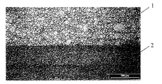
本発明の実施例を、次の実施例および図1に示されている、CuNiSn合金および鋼バンドからなる材料複合体の光学顕微鏡写真により詳述する。 Examples of the present invention will be described in detail with reference to the following examples and optical micrographs of a material composite comprising a CuNiSn alloy and a steel band, as shown in FIG.
実施例1:
実験のために、CuNi6Sn6を圧延された硬さ状態とし、および軟化焼き入れされた状態で施与材料として、鋼を様々な状態でベース材料として使用した。試料をブラシで処理し、引き続き清浄化した。
Example 1:
For the experiment, CuNi6Sn6 was in the rolled hardness state and softened and quenched as the application material and steel in various states as the base material. The sample was treated with a brush and subsequently cleaned.
引き続き直ぐに、様々なピッチ低下(Stichabnahme)で圧延を行った。銅と多成分の合金からなるバンドの出発厚は、約3mmであった。ベース材料の様々なバンド厚は、1.5mm、3および5mmであった。銅と多成分の合金の幅は、ベース材料の幅よりも約0.1から0.3mmほど狭かった。圧延出力、モーメントおよび出口温度を測定した。ベース材料の前記の厚さを有する各材料状態で処理し、1つの組み合わせ当たりそれぞれ5つの態様を実施した。圧延実験により、鋼へのCuNi6Sn6のクラッディングは難なく、良好な材料接着で実現することができることが判明した。 Immediately thereafter, rolling was carried out with various pitch drops (Stichabnahme). The starting thickness of the band of copper and multicomponent alloy was about 3 mm. The various band thicknesses of the base material were 1.5 mm, 3 and 5 mm. The width of the copper and multi-component alloy was about 0.1 to 0.3 mm narrower than the width of the base material. The rolling power, moment and outlet temperature were measured. Treated with each material state having the above thickness of base material, 5 embodiments were implemented per combination. From rolling experiments, it was found that the cladding of CuNi6Sn6 to steel was not difficult and could be achieved with good material adhesion.
図1は、CuNiSn合金1と鋼バンド2からなる材料複合体の断面の光学顕微鏡写真を示している。
FIG. 1 shows an optical micrograph of a cross section of a material composite composed of a
この場合、複合軸受け材料を、圧延クラッディングにより圧延された硬さ状態で、軟化焼き入れされた状態で、さらに焼き戻しされた状態で使用した。均一化温度は、500から800℃であり、焼き戻しを300から500℃の温度で行う。 In this case, the composite bearing material was used in a hardness state rolled by rolling cladding, in a softened and quenched state, and in a further tempered state. The homogenization temperature is 500 to 800 ° C., and tempering is performed at a temperature of 300 to 500 ° C.
実施例2:
以下では、スラストワッシャおよび軸受けブッシュなどのすべり素子のために、銅と多成分の合金を伴う材料複合体を製造する方法を記載する。この方法では、Cu−Ni−Sn系からなる鉛不含−軸受け材料を、溶融および鋳造により、深絞り用鋼に施与した。鉛不含の軸受け材料を、1000から1200℃の温度で鋳造したが、この際、層の構造は、連続的および断続的析出を伴うα−相から生じている。鋼およびCu−Ni−Sn合金からなる材料複合体を600から800℃の温度で焼き入れし、引き続き、層の表面をフライス盤に掛けた。この層状軸受け材料は、鋳造された状態でも、焼き戻しされた状態でも、すべり軸受け素子のために使用することができる。焼き戻しは、300から500℃の温度で実施した。
Example 2:
In the following, a method is described for producing a material composite with copper and a multicomponent alloy for sliding elements such as thrust washers and bearing bushes. In this method, a lead-free-bearing material made of a Cu-Ni-Sn system was applied to deep drawing steel by melting and casting. Lead-free bearing materials were cast at a temperature of 1000 to 1200 ° C., where the layer structure results from the α-phase with continuous and intermittent precipitation. The material composite consisting of steel and Cu—Ni—Sn alloy was quenched at a temperature of 600 to 800 ° C. and subsequently the surface of the layer was milled. This layered bearing material can be used for sliding bearing elements, both in the cast state and in the tempered state. Tempering was performed at a temperature of 300 to 500 ° C.
圧延および焼き入れなどの熱機械的処理により、軸受け層の鋳造構造は捏和(geknetet)された。バンドを、10から60%の成形度で冷間圧延し、引き続き、500から800℃の温度で焼き入れすることができる。複合軸受け材料は、様々な状態全てで、または鋳造状態で、捏和状態で、さらに焼き戻しされた状態で、すべり素子のために使用することができることが判明した。 The cast structure of the bearing layer was gekneted by thermomechanical treatment such as rolling and quenching. The band can be cold rolled at a forming degree of 10 to 60% and subsequently quenched at a temperature of 500 to 800 ° C. It has been found that the composite bearing material can be used for the sliding element in all different states, or in the cast state, in the kneaded state and in the tempered state.
実施例3
さらなる一連の実験では、様々なMn−Si比を有するブロックを鋳造し、引き続き、冷間にさらに加工した。実験された合金態様を表1にまとめる。鋳造ブロックを700から800℃の温度範囲で均一化し、次いで、切削した。複数回の冷間成形および中間焼き戻しにより、2.5から2.85mmの厚さを有するバンドを製造した。これらのバンドを冷間圧延し、引き続き、700から800℃の温度範囲で焼き入れして、十分な冷間成形能(Kaltumformvermoegen)を達成した。
Example 3
In a further series of experiments, blocks with various Mn-Si ratios were cast and subsequently further processed cold. The experimental alloy embodiments are summarized in Table 1. The cast block was homogenized in the temperature range of 700 to 800 ° C. and then cut. Bands having a thickness of 2.5 to 2.85 mm were produced by multiple cold forming and intermediate tempering. These bands were cold rolled and subsequently quenched in the temperature range of 700 to 800 ° C. to achieve sufficient cold forming ability (Kaltumformvermoegen).

予測されたように、ケイ化物で変性されたCu−Ni−Sn合金の冷間成形能は、さらなるケイ化物相を伴わないCu−Ni−Sn合金の場合よりもやや低いことが確認された。 As expected, it was confirmed that the cold forming ability of the Cu-Ni-Sn alloy modified with silicide was slightly lower than that of the Cu-Ni-Sn alloy without further silicide phase.
このようなベルトを、さらなる方法ステップで、圧延クラッディング法により、硬い材料複合体に合わせる。摩擦学的実験を伴う試験で、ケイ化物で変性されたCu−Ni−Sn合金に関して、変性されていない態様に対してかなり低い摩擦係数が証明された。したがってこの新規の変性合金は特に、エンジン、ギアおよびハイドロリックに関する各自動車領域ですべり素子(ブッシュ、スラストワッシャなど)として使用するための一次物質として適している。 Such a belt is combined in a further method step with a hard material composite by rolling cladding. Tests involving tribological experiments have demonstrated a much lower coefficient of friction for the unmodified embodiment for silicide-modified Cu-Ni-Sn alloys. This novel modified alloy is therefore particularly suitable as a primary material for use as a slip element (bush, thrust washer, etc.) in the automotive field for engines, gears and hydraulics.
前記の表の値を介して勿論、1.5重量%までのSi含有率および2.5重量派のMn含有率で変性されているCu−Ni−Sn−態様を、材料特性を改善しつつ調製することもできることが判明した。さらなる実験室実験もこのために既に実施し、限界値を確認した。 Through the values in the table above, of course, the Cu—Ni—Sn— modified with Si content up to 1.5 wt.% And Mn content of 2.5 wt. It has been found that it can also be prepared. Further laboratory experiments have already been carried out for this purpose and the limit values have been confirmed.
特に、Si含有率が0.7重量%までであり、Mn含有率が1.6重量%までであると実際に、製造技術的な観点からも、問題なく製造することができることが証明された。ケイ素およびマンガンの含有率がさらに高い場合には、鋳造パラメーターによって、相応する調節を慣用の対策の範囲内で実施しなければならない。 In particular, it was proved that the Si content is up to 0.7% by weight and the Mn content is up to 1.6% by weight. . If the content of silicon and manganese is even higher, the corresponding adjustments must be made within conventional measures, depending on the casting parameters.
ケイ素またはマンガン含有率が3重量%または5重量%の前記最大値を上回る場合には、特にバンド材料での辺縁部亀裂により、さらなる加工の際の困難を考慮しなければならない。 If the silicon or manganese content exceeds the maximum value of 3% by weight or 5% by weight, difficulties in further processing must be taken into account, especially due to edge cracks in the band material.
CuNiSn合金は、微細に分布しているマンガン−ニッケル−ケイ化物を含有し、これらは、合金マトリックスに包埋している。これらのケイ化物は、既に1100℃付近の温度範囲で初析出として溶融物中に生じる。溶融物組成の有利な選択では、利用可能なケイ素およびマンガンは、ケイ化物に対して過剰に存在するニッケル成分と共に析出する。この場合にケイ化物の形態で消費されるニッケル割合を、マトリックスの後続の形成のために、溶融物中での比較的高いニッケル割合により相応に考慮することができる。 CuNiSn alloys contain finely distributed manganese-nickel-silicides that are embedded in the alloy matrix. These silicides are already formed in the melt as initial precipitation in the temperature range near 1100 ° C. In an advantageous selection of the melt composition, the available silicon and manganese precipitate with a nickel component present in excess relative to the silicide. In this case, the proportion of nickel consumed in the form of silicide can be taken into account accordingly for the subsequent formation of the matrix due to the relatively high proportion of nickel in the melt.
ケイ化物の組成は、予め設定された化学量論に必ずしも対応しない。方法の実施によって、特に冷却速度によって、三元金属間相が、(Mn、Ni)xSiタイプのケイ化物の形態で析出し、これは、二元辺縁相Mn5Si3およびNi2Siの間の範囲に位置する。 The composition of the silicide does not necessarily correspond to a preset stoichiometry. By carrying out the method, in particular by the cooling rate, a ternary intermetallic phase precipitates in the form of a silicide of the (Mn, Ni) x Si type, which is a binary marginal phase Mn 5 Si 3 and Ni 2 Si. Located in the range between.
1 CuNiSn合金
2 鋼バンド
1 CuNiSn alloy 2 Steel band
Claims (4)
Ni 1.0から15.0重量%、
Sn 2.0から12.0重量%、
残分 Cuおよび不可避の不純物、
マンガン5重量%以下(0%を含む)、
ケイ素3重量%以下(0%を含む)、
Ti、Co、Cr、Al、Fe、Zn、Sbから選択される1種以上を1.5重量%以下(0%を含む)、
B、Zr、P、Sから選択される1種以上を0.5重量%以下(0%を含む)、
Pb25重量%以下(0%を含む)の組成を有し、銅合金からなる層が0.1から3mmの厚さを有する、600から800℃での焼き入れを少なくとも1回と、300から500℃での焼き戻しを少なくとも1回を受けている帯状の複合体において、鋼からなる支持層の表面と、銅合金からなる層との間に、銅合金の界面から鋼への拡散作用を阻止するための中間層が配置されていることを特徴とする帯状の複合体。 Rolled layers of copper alloy, a composite of the strip being combined so as not to be separated from the supporting layer made of steel, this time, copper alloy,
Ni 1.0 to 15.0% by weight,
Sn 2.0 to 12.0% by weight,
Residual Cu and inevitable impurities,
5% by weight or less of manganese (including 0%),
3% by weight or less of silicon (including 0%),
1.5% by weight or less (including 0%) of one or more selected from Ti, Co, Cr, Al, Fe, Zn, and Sb,
0.5% by weight or less (including 0%) of one or more selected from B, Zr, P, and S,
Pb having a composition of 25% by weight or less (including 0%) , and a layer made of a copper alloy having a thickness of 0.1 to 3 mm, and quenching at 600 to 800 ° C. at least once, 300 to 500 blocking baked in a strip-shaped composite undergoing at least once back at ° C., and the surface of the supporting layer made of steel, between the layer of copper alloy, the diffusion effect of the interface between the copper alloy to the steel A band-shaped composite, wherein an intermediate layer is disposed for the purpose.
Applications Claiming Priority (2)
| Application Number | Priority Date | Filing Date | Title |
|---|---|---|---|
| DE102006019826A DE102006019826B3 (en) | 2006-04-28 | 2006-04-28 | Strip-like composite material for composite sliding elements or connectors comprises a layer made from a copper multiple material alloy with a protective layer of deep-drawing steel, tempering steel or case hardening steel |
| DE102006019826.3 | 2006-04-28 |
Publications (2)
| Publication Number | Publication Date |
|---|---|
| JP2007297706A JP2007297706A (en) | 2007-11-15 |
| JP5307348B2 true JP5307348B2 (en) | 2013-10-02 |
Family
ID=38282481
Family Applications (1)
| Application Number | Title | Priority Date | Filing Date |
|---|---|---|---|
| JP2007098012A Active JP5307348B2 (en) | 2006-04-28 | 2007-04-04 | Band-shaped composite, method of using the same, and composite slip element comprising the band-shaped composite |
Country Status (6)
| Country | Link |
|---|---|
| US (1) | US7790295B2 (en) |
| EP (1) | EP1850018B2 (en) |
| JP (1) | JP5307348B2 (en) |
| KR (1) | KR101247581B1 (en) |
| AT (1) | ATE435375T1 (en) |
| DE (2) | DE102006019826B3 (en) |
Families Citing this family (27)
| Publication number | Priority date | Publication date | Assignee | Title |
|---|---|---|---|---|
| AT504088B1 (en) * | 2006-09-01 | 2008-11-15 | Miba Gleitlager Gmbh | BEARINGS |
| DE102007049383A1 (en) * | 2007-10-15 | 2009-04-16 | Wickeder Westfalenstahl Gmbh | Composite material, in particular friction composite material and method for producing a composite material |
| WO2010114524A1 (en) * | 2009-03-31 | 2010-10-07 | Questek Innovations Llc | Beryllium-free high-strength copper alloys |
| JP5684977B2 (en) * | 2009-08-31 | 2015-03-18 | 株式会社ダイヤメット | Cu-based sintered sliding member |
| AT509459B1 (en) * | 2010-04-15 | 2011-09-15 | Miba Gleitlager Gmbh | anti-fretting |
| AT509867B1 (en) * | 2010-04-15 | 2011-12-15 | Miba Gleitlager Gmbh | MULTILAYER BEARING BEARING WITH AN ANTIFRETTING LAYER |
| US9024493B2 (en) | 2010-12-30 | 2015-05-05 | Dresser-Rand Company | Method for on-line detection of resistance-to-ground faults in active magnetic bearing systems |
| US8994237B2 (en) | 2010-12-30 | 2015-03-31 | Dresser-Rand Company | Method for on-line detection of liquid and potential for the occurrence of resistance to ground faults in active magnetic bearing systems |
| DE102011013883A1 (en) * | 2011-03-04 | 2012-09-06 | Ks Gleitlager Gmbh | Plain bearing composite material |
| US9551349B2 (en) | 2011-04-08 | 2017-01-24 | Dresser-Rand Company | Circulating dielectric oil cooling system for canned bearings and canned electronics |
| GB2503620B (en) * | 2011-04-08 | 2017-12-20 | Dresser-Rand Company | Self-lubricating snubber bearing |
| US20150192172A1 (en) * | 2011-05-17 | 2015-07-09 | Dresser-Rand Company | Coast down bushing for magnetic bearing systems |
| WO2012166236A1 (en) | 2011-05-27 | 2012-12-06 | Dresser-Rand Company | Segmented coast-down bearing for magnetic bearing systems |
| US8851756B2 (en) | 2011-06-29 | 2014-10-07 | Dresser-Rand Company | Whirl inhibiting coast-down bearing for magnetic bearing systems |
| CN104137191A (en) * | 2011-12-28 | 2014-11-05 | 矢崎总业株式会社 | Ultrafine conductor material, ultrafine conductor, method for preparing ultrafine conductor, and ultrafine electrical wire |
| CN102941701A (en) * | 2012-11-14 | 2013-02-27 | 无锡市光源不锈钢制品有限公司 | Copper-plated stainless steel band |
| DE102013201720B4 (en) * | 2013-02-01 | 2019-05-09 | Ks Gleitlager Gmbh | Metallic sliding bearing composite material with a metallic support layer |
| EP3536819B1 (en) * | 2013-03-14 | 2024-04-17 | Materion Corporation | Process for improving formability of wrought copper-nickel-tin alloys |
| DE102013005158A1 (en) * | 2013-03-26 | 2014-10-02 | Kme Germany Gmbh & Co. Kg | copper alloy |
| CN105143480B (en) * | 2013-04-23 | 2017-12-15 | 美题隆公司 | Adonic with high tenacity |
| AT514961B1 (en) * | 2013-12-23 | 2015-05-15 | Miba Gleitlager Gmbh | Multilayer plain bearings |
| US9938608B2 (en) | 2014-08-21 | 2018-04-10 | Materion Corporation | Composite articles comprising spinodal copper-nickel-tin-manganese-phosphorus alloy matrix material |
| CN107849699A (en) * | 2015-08-06 | 2018-03-27 | 日产自动车株式会社 | Sliding component and its manufacture method |
| CN107557605A (en) * | 2016-06-30 | 2018-01-09 | 苏州东南佳新材料股份有限公司 | A kind of impregnating metal material of magnetic suspension train carbon sliding block |
| CN106282650A (en) * | 2016-09-18 | 2017-01-04 | 山东大学 | A kind of boron-rich micro-nano ball strengthens Cu-base composites and preparation method thereof |
| CN114959230B (en) * | 2017-02-04 | 2024-08-16 | 美题隆公司 | Copper nickel tin alloy strip or plate and preparation method thereof |
| JP7214451B2 (en) * | 2018-02-13 | 2023-01-30 | 株式会社栗本鐵工所 | Copper alloy |
Family Cites Families (20)
| Publication number | Priority date | Publication date | Assignee | Title |
|---|---|---|---|---|
| FR793409A (en) * | 1934-10-31 | 1936-01-24 | Forges Et Ateliers De La Foule | Tin and chrome bronzes |
| DE3304740C2 (en) * | 1983-02-11 | 1985-02-21 | Glyco-Metall-Werke Daelen & Loos Gmbh, 6200 Wiesbaden | Multi-layer plain bearings |
| DE3642825C1 (en) † | 1986-12-16 | 1988-01-21 | Wieland Werke Ag | Use of a copper-nickel-aluminium-tin alloy as a material for slide bearings |
| JP2605833B2 (en) | 1988-10-17 | 1997-04-30 | 三菱マテリアル株式会社 | Transmission synchronous ring made of Cu-based sintered alloy |
| JPH02225651A (en) † | 1988-11-15 | 1990-09-07 | Mitsubishi Electric Corp | Manufacture of high strength cu-ni-sn alloy |
| US5089057A (en) † | 1989-09-15 | 1992-02-18 | At&T Bell Laboratories | Method for treating copper-based alloys and articles produced therefrom |
| JP2724903B2 (en) * | 1990-05-23 | 1998-03-09 | 矢崎総業 株式会社 | High-strength copper alloy for electrical conduction with excellent bending resistance |
| DE4121994C2 (en) † | 1991-07-03 | 1995-06-08 | Wieland Werke Ag | Process for producing a copper-nickel-tin alloy and its use |
| JP2529489B2 (en) † | 1991-07-09 | 1996-08-28 | 三菱電機株式会社 | Copper-nickel based alloy |
| DE4411762A1 (en) † | 1994-04-06 | 1995-10-12 | Kolbenschmidt Ag | Plain bearing material |
| JPH08283889A (en) * | 1995-04-14 | 1996-10-29 | Chuetsu Gokin Chuko Kk | High strength and high hardness copper alloy |
| JPH1030137A (en) * | 1996-07-15 | 1998-02-03 | Daido Metal Co Ltd | Copper base sliding member |
| DE19754221A1 (en) * | 1997-12-06 | 1999-06-17 | Federal Mogul Wiesbaden Gmbh | Layered composite material for plain bearings with lead-free sliding layer |
| WO1999043963A1 (en) * | 1998-02-24 | 1999-09-02 | Taiho Kogyo Co., Ltd. | Sliding bearing for internal combustion engine |
| KR100332578B1 (en) * | 1999-07-14 | 2002-04-17 | 박영구 | bond for diamond segment and the method of diamond segment using the same |
| DE19963385C1 (en) * | 1999-12-28 | 2001-01-25 | Federal Mogul Wiesbaden Gmbh | Composite material layer for sliding bearings has a sliding layer made of a tin matrix in which tin-copper particles are embedded |
| JP2001241445A (en) | 2000-02-28 | 2001-09-07 | Daido Metal Co Ltd | Copper based sliding material, its manufacturing method, and slide bearing |
| JP2003194061A (en) † | 2001-12-27 | 2003-07-09 | Daido Metal Co Ltd | Copper-based sintered sliding material and its manufacturing method |
| DE10324952A1 (en) * | 2003-06-03 | 2004-12-23 | Valco Edelstahl Und Schweisstechnik Gmbh | Soldering powder material for very strong ultra-thin sheet metal work pieces, or to cover an organically coated layer with a fine solder mantle |
| US20070253858A1 (en) * | 2006-04-28 | 2007-11-01 | Maher Ababneh | Copper multicomponent alloy and its use |
-
2006
- 2006-04-28 DE DE102006019826A patent/DE102006019826B3/en not_active Revoked
-
2007
- 2007-03-02 KR KR1020070021014A patent/KR101247581B1/en active IP Right Grant
- 2007-03-15 US US11/724,380 patent/US7790295B2/en active Active
- 2007-04-04 JP JP2007098012A patent/JP5307348B2/en active Active
- 2007-04-19 AT AT07007948T patent/ATE435375T1/en active
- 2007-04-19 EP EP07007948A patent/EP1850018B2/en active Active
- 2007-04-19 DE DE502007000959T patent/DE502007000959D1/en active Active
Also Published As
| Publication number | Publication date |
|---|---|
| DE502007000959D1 (en) | 2009-08-13 |
| ATE435375T1 (en) | 2009-07-15 |
| EP1850018B2 (en) | 2012-06-13 |
| EP1850018B1 (en) | 2009-07-01 |
| KR101247581B1 (en) | 2013-03-26 |
| US20070254180A1 (en) | 2007-11-01 |
| JP2007297706A (en) | 2007-11-15 |
| EP1850018A2 (en) | 2007-10-31 |
| EP1850018A3 (en) | 2008-05-21 |
| KR20070106390A (en) | 2007-11-01 |
| DE102006019826B3 (en) | 2007-08-09 |
| US7790295B2 (en) | 2010-09-07 |
Similar Documents
| Publication | Publication Date | Title |
|---|---|---|
| JP5307348B2 (en) | Band-shaped composite, method of using the same, and composite slip element comprising the band-shaped composite | |
| JP5154410B2 (en) | Sliding bearing composite material, use and manufacturing method | |
| US10494701B2 (en) | Composite material for a sliding bearing | |
| JP2007297707A (en) | Multicomponent copper alloy and its use | |
| KR100600075B1 (en) | Friction bearing having intermediate layer, notably binding layer, made of an alloy on aluminium basis | |
| JP3857503B2 (en) | Aluminum bearing alloy | |
| JP5289941B2 (en) | Sliding bearing composite material, use of sliding bearing composite material, and manufacturing method of sliding bearing composite material | |
| JP3958515B2 (en) | Multilayer bearing and manufacturing method thereof | |
| KR102393772B1 (en) | Copper-nickel-tin alloy, method for manufacturing and use thereof | |
| KR102420968B1 (en) | Copper-nickel-tin alloy, method for manufacturing and use thereof | |
| JP2002285262A (en) | Copper based double layered sliding material | |
| KR101431355B1 (en) | Aluminum alloy for slide bearing, slide bearing and method for producing same | |
| JP6679742B2 (en) | Tin-containing copper alloy, its manufacturing method, and its use | |
| JPH07179964A (en) | Copper-lead alloy bearing | |
| JP2006022896A (en) | Double-layered bearing material and its manufacturing method | |
| JP6679741B2 (en) | Tin-containing copper alloy, its manufacturing method, and its use | |
| JP3857628B2 (en) | Aluminum-based multilayer bearing | |
| CN108506331B (en) | Sliding element made of copper alloy | |
| JPH1030137A (en) | Copper base sliding member | |
| JPS5844140B2 (en) | Composite sliding material | |
| JP3776228B2 (en) | Heat treatment reinforced aluminum sliding material and method for producing the same | |
| JPH08261240A (en) | Sliding bearing made of aluminium alloy | |
| JPH02290940A (en) | Bearing alloy |
Legal Events
| Date | Code | Title | Description |
|---|---|---|---|
| A621 | Written request for application examination |
Free format text: JAPANESE INTERMEDIATE CODE: A621 Effective date: 20100305 |
|
| A977 | Report on retrieval |
Free format text: JAPANESE INTERMEDIATE CODE: A971007 Effective date: 20120920 |
|
| A131 | Notification of reasons for refusal |
Free format text: JAPANESE INTERMEDIATE CODE: A131 Effective date: 20121009 |
|
| A521 | Request for written amendment filed |
Free format text: JAPANESE INTERMEDIATE CODE: A523 Effective date: 20121130 |
|
| A131 | Notification of reasons for refusal |
Free format text: JAPANESE INTERMEDIATE CODE: A131 Effective date: 20130318 |
|
| A521 | Request for written amendment filed |
Free format text: JAPANESE INTERMEDIATE CODE: A523 Effective date: 20130514 |
|
| TRDD | Decision of grant or rejection written | ||
| A01 | Written decision to grant a patent or to grant a registration (utility model) |
Free format text: JAPANESE INTERMEDIATE CODE: A01 Effective date: 20130618 |
|
| A61 | First payment of annual fees (during grant procedure) |
Free format text: JAPANESE INTERMEDIATE CODE: A61 Effective date: 20130627 |
|
| R150 | Certificate of patent or registration of utility model |
Ref document number: 5307348 Country of ref document: JP Free format text: JAPANESE INTERMEDIATE CODE: R150 |
|
| R250 | Receipt of annual fees |
Free format text: JAPANESE INTERMEDIATE CODE: R250 |
|
| R250 | Receipt of annual fees |
Free format text: JAPANESE INTERMEDIATE CODE: R250 |
|
| R250 | Receipt of annual fees |
Free format text: JAPANESE INTERMEDIATE CODE: R250 |
|
| R250 | Receipt of annual fees |
Free format text: JAPANESE INTERMEDIATE CODE: R250 |
|
| R250 | Receipt of annual fees |
Free format text: JAPANESE INTERMEDIATE CODE: R250 |
|
| R250 | Receipt of annual fees |
Free format text: JAPANESE INTERMEDIATE CODE: R250 |
|
| R250 | Receipt of annual fees |
Free format text: JAPANESE INTERMEDIATE CODE: R250 |
|
| R250 | Receipt of annual fees |
Free format text: JAPANESE INTERMEDIATE CODE: R250 |
|
| R250 | Receipt of annual fees |
Free format text: JAPANESE INTERMEDIATE CODE: R250 |