JP5288917B2 - Paste coating apparatus and paste coating method - Google Patents
Paste coating apparatus and paste coating method Download PDFInfo
- Publication number
- JP5288917B2 JP5288917B2 JP2008179086A JP2008179086A JP5288917B2 JP 5288917 B2 JP5288917 B2 JP 5288917B2 JP 2008179086 A JP2008179086 A JP 2008179086A JP 2008179086 A JP2008179086 A JP 2008179086A JP 5288917 B2 JP5288917 B2 JP 5288917B2
- Authority
- JP
- Japan
- Prior art keywords
- coating
- paste
- application
- heads
- head
- Prior art date
- Legal status (The legal status is an assumption and is not a legal conclusion. Google has not performed a legal analysis and makes no representation as to the accuracy of the status listed.)
- Active
Links
Images

Classifications
-
- B—PERFORMING OPERATIONS; TRANSPORTING
- B05—SPRAYING OR ATOMISING IN GENERAL; APPLYING FLUENT MATERIALS TO SURFACES, IN GENERAL
- B05C—APPARATUS FOR APPLYING FLUENT MATERIALS TO SURFACES, IN GENERAL
- B05C11/00—Component parts, details or accessories not specifically provided for in groups B05C1/00 - B05C9/00
- B05C11/10—Storage, supply or control of liquid or other fluent material; Recovery of excess liquid or other fluent material
- B05C11/1044—Apparatus or installations for supplying liquid or other fluent material to several applying apparatus or several dispensing outlets, e.g. to several extrusion nozzles
-
- B—PERFORMING OPERATIONS; TRANSPORTING
- B05—SPRAYING OR ATOMISING IN GENERAL; APPLYING FLUENT MATERIALS TO SURFACES, IN GENERAL
- B05C—APPARATUS FOR APPLYING FLUENT MATERIALS TO SURFACES, IN GENERAL
- B05C5/00—Apparatus in which liquid or other fluent material is projected, poured or allowed to flow on to the surface of the work
- B05C5/02—Apparatus in which liquid or other fluent material is projected, poured or allowed to flow on to the surface of the work the liquid or other fluent material being discharged through an outlet orifice by pressure, e.g. from an outlet device in contact or almost in contact, with the work
- B05C5/0225—Apparatus in which liquid or other fluent material is projected, poured or allowed to flow on to the surface of the work the liquid or other fluent material being discharged through an outlet orifice by pressure, e.g. from an outlet device in contact or almost in contact, with the work characterised by flow controlling means, e.g. valves, located proximate the outlet
-
- B—PERFORMING OPERATIONS; TRANSPORTING
- B05—SPRAYING OR ATOMISING IN GENERAL; APPLYING FLUENT MATERIALS TO SURFACES, IN GENERAL
- B05D—PROCESSES FOR APPLYING FLUENT MATERIALS TO SURFACES, IN GENERAL
- B05D1/00—Processes for applying liquids or other fluent materials
- B05D1/26—Processes for applying liquids or other fluent materials performed by applying the liquid or other fluent material from an outlet device in contact with, or almost in contact with, the surface
-
- B—PERFORMING OPERATIONS; TRANSPORTING
- B05—SPRAYING OR ATOMISING IN GENERAL; APPLYING FLUENT MATERIALS TO SURFACES, IN GENERAL
- B05D—PROCESSES FOR APPLYING FLUENT MATERIALS TO SURFACES, IN GENERAL
- B05D3/00—Pretreatment of surfaces to which liquids or other fluent materials are to be applied; After-treatment of applied coatings, e.g. intermediate treating of an applied coating preparatory to subsequent applications of liquids or other fluent materials
- B05D3/12—Pretreatment of surfaces to which liquids or other fluent materials are to be applied; After-treatment of applied coatings, e.g. intermediate treating of an applied coating preparatory to subsequent applications of liquids or other fluent materials by mechanical means
Landscapes
- Coating Apparatus (AREA)
- Engineering & Computer Science (AREA)
- Mechanical Engineering (AREA)
- Details Or Accessories Of Spraying Plant Or Apparatus (AREA)
- Application Of Or Painting With Fluid Materials (AREA)
Description
本発明は、塗布対象物にペーストを塗布するペースト塗布装置及びペースト塗布方法に関する。 The present invention relates to a paste application apparatus and a paste application method for applying a paste to an object to be applied.
ペースト塗布装置は、液晶表示パネルなどの様々な装置を製造するために用いられている。このペースト塗布装置は、塗布対象物に対してペーストを吐出して塗布する塗布ヘッドを備えており、その塗布ヘッドを移動させながら塗布対象物にペーストを塗布し、塗布対象物上に所定のペーストパターンを形成する(例えば、特許文献1参照)。特に、液晶表示パネルの製造では、2枚の基板を貼り合わせるため、ペースト塗布装置は、塗布対象物である基板に対して液晶表示パネルの表示領域を囲むように、シール剤などのシール性及び接着性を有するペーストを塗布する。 Paste applicators are used to manufacture various devices such as liquid crystal display panels. This paste coating apparatus includes a coating head that discharges and applies a paste to a coating target, and applies the paste to the coating target while moving the coating head, and a predetermined paste on the coating target. A pattern is formed (see, for example, Patent Document 1). In particular, in the manufacture of a liquid crystal display panel, since two substrates are bonded together, the paste application device has a sealing property such as a sealing agent and the like so as to surround the display area of the liquid crystal display panel with respect to the substrate that is the application target. An adhesive paste is applied.
近年、液晶表示パネルのパネルサイズは、携帯電話などのモバイル用途の小型パネルからテレビなどの大型パネルまで多種多様となってきている。また、パネル価格も低価格となり、パネルの生産性向上の要求も厳しくなってきている。通常、必要なパネルを必要量生産するためには、1枚の基板から複数のパネルを取る多面取りが行われている。この場合には、パネルの面取り数に合わせた数の塗布ヘッドを装置に取り付け、描画条件出しを行って描画を行い、パネルサイズ及び面取り数を変更する際には、段取り替えとして塗布ヘッドの取り付けあるいは取り外しにより塗布ヘッド数を増減させ、再度、描画条件出しを行うことになる。通常、この段取り替えにより生産は中断される。
しかしながら、従来のペースト塗布装置では、パネルサイズ及び面取り数を変更する際、塗布ヘッドの取り付けあるいは取り外しを行い、さらに、描画条件出しを行う必要があるため、段取り替え時間は数十分から数時間となり、生産性が低下してしまう。 However, in the conventional paste coating apparatus, when changing the panel size and the number of chamfers, it is necessary to attach or remove the coating head and to determine the drawing conditions. As a result, productivity decreases.
ここで、段取り替え時間の短縮としては、描画条件出しの際の塗布量調整を行う場合、塗布されたペーストの塗布量を測定する測定器を増やして複数の塗布ヘッドにより描画したそれぞれのペーストパターンを同時に測定したり、繋ぎ検査を行う場合、画像処理装置を増やしたりすることが行われているが、各機器の取り付けスペースの確保が難しいうえに装置価格も上昇してしまう。 Here, as shortening the setup change time, when adjusting the coating amount when drawing conditions are set, each paste pattern drawn by a plurality of coating heads by increasing the number of measuring instruments for measuring the coating amount of the applied paste However, it is difficult to secure an installation space for each device and the device price also increases.
本発明は上記に鑑みてなされたものであり、その目的は、機器追加及び価格上昇を抑えつつ、段取り替え時間の短縮により生産性を向上させることができるペースト塗布装置及びペースト塗布方法を提供することである。 The present invention has been made in view of the above, and an object of the present invention is to provide a paste coating apparatus and a paste coating method capable of improving productivity by shortening the setup change time while suppressing the addition of equipment and price increase. That is.
本発明の実施の形態に係る第1の特徴は、ペースト塗布装置において、塗布対象物にペーストを吐出して塗布する塗布動作及び塗布性能を維持するための維持動作をそれぞれ行う複数の塗布ヘッドと、前記複数の塗布ヘッドの前記塗布動作及び前記維持動作を制御する制御部と、を備え、前記制御部は、前記複数の塗布ヘッド中の塗布実行対象の塗布ヘッドに対して前記前記塗布動作を実行させ、前記塗布実行対象の塗布ヘッドに対して前記維持動作を実行させるとき、前記複数の塗布ヘッド中の塗布実行非対象の塗布ヘッドに対しても前記維持動作を実行させることである。 A first feature according to an embodiment of the present invention is that, in the paste application device, a plurality of application heads that respectively perform an application operation for discharging and applying a paste to an application object and a maintenance operation for maintaining the application performance; A control unit that controls the coating operation and the maintaining operation of the plurality of coating heads, and the control unit performs the coating operation on a coating execution target coating head in the plurality of coating heads. is executed, the time to execute the maintenance operation on the coating executed of the coating head is to perform the maintenance work for the plurality of application execution asymmetric coating head in the coating head.
本発明の実施の形態に係る第2の特徴は、ペースト塗布方法において、塗布対象物にペーストを吐出して塗布する塗布動作及び塗布性能を維持するための維持動作をそれぞれ行う複数の塗布ヘッド中の塗布実行対象の塗布ヘッドに対して塗布動作を実行させる工程と、前記塗布実行対象の塗布ヘッドに対して前記維持動作を実行させる工程と、前記塗布実行対象の塗布ヘッドに対して前記維持動作を実行させるとき、前記複数の塗布ヘッド中の塗布実行非対象の塗布ヘッドに対しても前記維持動作を実行させる工程とを有することである。 A second feature according to the embodiment of the present invention is that, in the paste coating method, a plurality of coating heads that respectively perform a coating operation for discharging and applying a paste to a coating target and a maintenance operation for maintaining coating performance. Performing a coating operation on the coating execution target coating head, performing a maintenance operation on the coating execution target coating head, and maintaining the coating operation target coating head. when to be executed, it is to have a step of performing the maintenance work to the plurality of coating heads of the coating run non-target in the coating head.
本発明によれば、機器追加及び価格上昇を抑えつつ、段取り替え時間の短縮により生産性を向上させることができるペースト塗布装置及びペースト塗布方法を提供することができる。 According to the present invention, it is possible to provide a paste coating apparatus and a paste coating method capable of improving productivity by shortening the setup change time while suppressing equipment addition and price increase.
本発明の実施の一形態について図面を参照して説明する。 An embodiment of the present invention will be described with reference to the drawings.
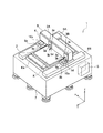
図1に示すように、本発明の実施の形態に係るペースト塗布装置1は、塗布対象物としての基板Kが水平状態(図1中、X軸方向とそれに直交するY軸方向に沿う状態)で載置される基板ステージ2と、その基板ステージ2上の基板Kにシール剤などのシール性及び接着性を有するペーストをそれぞれ塗布する複数の塗布ヘッド3A、3Bと、それらの塗布ヘッド3A、3BをX軸方向(図1中)に移動可能に支持してX軸方向に沿って移動させるX軸移動機構4と、そのX軸移動機構4を介して各塗布ヘッド3A、3Bを支持する支持部材5と、その支持部材5をY軸方向(図1中)に移動可能に支持してY軸方向に沿って移動させる一対のY軸移動機構6A、6Bと、基板ステージ2や一対のY軸移動機構6A、6Bなどを支持する架台7と、各部を制御する制御部8とを備えている。
As shown in FIG. 1, in the
基板ステージ2は、架台7の上面に固定されて設けられた載置台である。この基板ステージ2には、前後(Y軸方向)に2つの載置面が同じ高さで形成されており、奥側の載置面には、製造用の基板Kが載置され、手前側の載置面には、捨て打ち用の塗布対象物としての捨て打ち基板Kaが載置される。製造用の基板K及び捨て打ち基板Kaとしては、ガラス基板などを用いる。基板ステージ2は、製造用の基板K及び捨て打ち基板Kaを吸着する吸着機構(図示せず)を備えており、その吸着機構により上面の載置面に基板K及び捨て打ち基板Kaを固定して保持する。なお、吸着機構としては、例えば真空吸着機構などを用いる。
The substrate stage 2 is a mounting table that is fixed to the upper surface of the
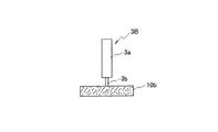
各塗布ヘッド3A、3Bは、ペーストを収容するシリンジなどの収容筒3aと、その収容筒3aに連通してペーストを吐出するノズル3bとをそれぞれ有している。これらの塗布ヘッド3A、3Bは、気体供給チューブなどを介して気体供給部(いずれも図示せず)にそれぞれ接続されている。各塗布ヘッド3A、3Bは、それぞれ収容筒3a内に供給される気体により、その収容筒3a内部のペーストをノズル3bから吐出する。
Each
これらの塗布ヘッド3A、3Bは、YZ軸移動機構3cを介してX軸移動機構4にそれぞれ設けられている。このYZ軸移動機構3cは、個々の塗布ヘッド3A、3Bを個別に支持してY軸方向に移動させる移動機構であって、さらに、水平面に直交するZ軸方向(図1中)、すなわち基板ステージ2に対して塗布ヘッド3A、3Bを接離させる接離方向に移動させる移動機構である。なお、YZ軸移動機構3cとしては、例えばボールネジを用いる送りネジ機構などを用いる。
These
また、YZ軸移動機構3cには、基板ステージ2上の基板Kあるいは捨て打ち基板Kaの表面までの距離を測定するレーザ変位計等の距離測定器3dが設けられている。この距離測定器3dは制御部8に電気的に接続されており、距離測定器3dにより測定された離間距離は、基板Kあるいは捨て打ち基板Kaの表面とノズル3bとのギャップを所定のギャップに保つギャップ制御に用いられる。
Further, the YZ axis moving mechanism 3c is provided with a
X軸移動機構4は支持部材5の前面に設けられている。このX軸移動機構4は、2つの塗布ヘッド3A、3BをX軸方向に移動可能に支持しており、それらの塗布ヘッド3A、3BをX軸方向、すなわち支持部材5に沿って移動させる移動機構である。なお、X軸移動機構4としては、例えば、リニアモータを用いたリニアモータ機構やボールネジを用いた送りネジ機構などを用いる。
The
支持部材5はX軸移動機構4を介して2つの塗布ヘッド3A、3Bを支持するコラムである。この支持部材5は、その移動方向(Y軸方向)に交差する方向、例えば直交する方向(X軸方向)に延伸させ、例えば直方体形状にそれぞれ形成されている。また、支持部材5は基板ステージ2の載置面に対して平行に設けられている。このような支持部材5は、一対のY軸移動機構6A、6BによりY軸方向に移動し、基板ステージ2の載置面に対向する位置に各塗布ヘッド3A、3Bを位置付ける。
The
一対のY軸移動機構6A、6Bは、基板ステージ2を両側から挟むように架台7の上面にそれぞれ設けられている。Y軸移動機構6Aは、支持部材5の端部が固定されて載置される支持台6aやY軸方向に伸びるガイドレール(図示せず)などを備えている。支持台6aはガイドレールに沿ってY軸方向に移動可能に形成されている。同様に、Y軸移動機構6Bも、支持部材5の端部が固定されて載置される支持台6bやY軸方向に伸びるガイドレール(図示せず)などを備えている。支持台6bもガイドレールに沿ってY軸方向に移動可能に形成されている。すなわち、一対のY軸移動機構6A、6Bは、それぞれ協調して支持部材5をY軸方向に移動可能に支持しており、その支持部材5をY軸方向に沿って移動させる移動機構である。なお、一対のY軸移動機構6A、6Bとしては、例えば、リニアモータを用いたリニアモータ機構やボールネジを用いた送りネジ機構などを用いる。
The pair of Y-
支持台6aには、塗布ヘッド3Aから吐出されたペーストを受け取る受け部材9aと、塗布ヘッド3Aを清掃するための清掃部材10aとが設けられている。これらの受け部材9a及び清掃部材10aは、各塗布ヘッド3A、3Bの移動方向であるX軸方向に並べて設けられている。同様に、支持台6bにも、塗布ヘッド3Bから吐出されたペーストを受け取る受け部材9bと、塗布ヘッド3Bを清掃するための清掃部材10bとが設けられている。これらの受け部材9b及び清掃部材10bも、各塗布ヘッド3A、3Bの移動方向であるX軸方向に並べて設けられている。なお、各受け部材9a、9bとしては、例えば、トレーなどの受皿を用いる。また、各清掃部材10a、10bとしては、例えば、ノズル3bに残留するペーストを吸収して除去する吸収部材やそのペーストを拭き取る拭取り部材など(例えば、スポンジ状あるいは布状の吸収部材や拭取り部材)を用いる。
The support base 6a is provided with a receiving
架台7は、床面上に設置され、基板ステージ2や一対のY軸移動機構6A、6Bなどを床面から所定の高さ位置に支持する架台である。架台7の上面は平面に形成されており、この架台7の上面には、基板ステージ2や一対のY軸移動機構6A、6Bなどが載置されている。
The
制御部8は、架台7内に設けられており、各部を集中的に制御するマイクロコンピュータと、ペースト塗布に関する塗布情報や各種のプログラムなどを記憶する記憶部と(いずれも図示せず)を備えている。この制御部8には、各種の設定値を設定するためなどに操作者により入力操作される入力部(図示せず)が接続されている。なお、塗布情報は、所定の塗布パターン(ペーストパターン)や描画速度、ペーストの塗布量(吐出量)等に関する情報を含んでいる。
The
この制御部8は、塗布情報や各種のプログラムに基づいて、各塗布ヘッド3A、3Bの中から塗布実行対象の塗布ヘッドを選択し、X軸移動機構4や一対のY軸移動機構6A、6Bなどを制御し、選択した塗布ヘッド3A、3Bのノズル3bと基板ステージ2上の製造用の基板Kとをその基板Kの表面方向に平行に相対移動させ、製造用の基板K上に所定塗布パターンにペーストを塗布する。このとき、制御部8は、距離測定器3dにより測定された離間距離によるフィードバック制御を行い、基板Kの表面とノズル3bとのギャップを所定のギャップに保つように制御する(ギャップ制御)。また、制御部8は、各塗布ヘッド3A、3Bの各々の収容筒3aに供給する気体の圧力をそれぞれ調整し、ペーストを吐出する際にペーストに加える吐出圧力を制御する(吐出量制御)。
The
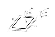
ここで、制御部8は、面取り数に応じて各塗布ヘッド3A、3Bの中から塗布実行対象の塗布ヘッド(塗布に使用する塗布ヘッド)を選択する。例えば、面取り数が1に設定されている場合には、制御部8は各塗布ヘッド3A、3Bから塗布実行対象の塗布ヘッドとして塗布ヘッド3Aを選択し、選択した塗布ヘッド3Aに対して塗布動作を実行させることになる。これにより、図2に示すように、枠形状の1つのペーストパターンP1が製造用の基板K上に塗布される。この塗布動作中、塗布実行非対象(塗布に使用しない塗布ヘッド)の塗布ヘッド3Bは、製造用の基板Kに対向しない待機位置(例えば、塗布ヘッド3Bが受け部材9bあるいは清掃部材10bに対向する位置)で待機する。このような塗布動作が製造用の基板Kの交換毎に行われ、所定の生産枚数分繰り返される。
Here, the
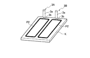
その後、段取り替えが行われ、パネルサイズ及び面取り数が変更される。面取り数が2に設定された場合には、制御部8は各塗布ヘッド3A、3Bから塗布実行対象の塗布ヘッドとして両方の塗布ヘッド3A、3Bを選択し、選択した各塗布ヘッド3A、3Bに対して塗布動作を実行させることになる。これにより、図3に示すように、枠形状の2つのペーストパターンP2が製造用の基板K上に塗布される。このような塗布動作が製造用の基板Kの交換毎に行われ、所定の生産枚数分繰り返される。なお、製造を行う前には、製造用の基板Kにペーストを描画する際の描画条件出し(描画速度や塗布量などの描画条件出し)は完了している。
Thereafter, setup change is performed, and the panel size and the number of chamfers are changed. When the number of chamfers is set to 2, the
このような段取り替えを含む製造工程中、制御部8は、所望のタイミングで、塗布実行対象の塗布ヘッドに対して(面取り数が1である場合、塗布ヘッド3Aに対して、また、面取り数が2である場合、各塗布ヘッド3A、3Bに対して)、塗布性能を維持するための維持動作を実行させる。このとき、制御部8は、各塗布ヘッド3A、3B中の塗布実行非対象の塗布ヘッドに対しても(面取り数が1である場合、塗布ヘッド3Bに対しても)、維持動作を実行させる。したがって、各塗布ヘッド3A、3Bは、製造用の基板Kにペーストを吐出して塗布する塗布動作を面取り数に応じてそれぞれ行う一方、面取り数に関係なく、すなわち塗布実行対象の塗布ヘッドであるか否かに関係なく維持動作をそれぞれ同時に行うことになる。これにより、全ての塗布ヘッド3A、3Bの塗布性能を常に良好に維持することができる。
During the manufacturing process including such a setup change, the
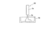
維持動作は、図4に示すように、捨て打ち基板Kaに向けてペーストを吐出して塗布する捨て打ち動作、図5に示すように、受け部材9a、9bに向けてペーストを吐出する捨て吐出動作、図6に示すように、ノズル3bを清掃部材10a、10bに接触させる清掃動作、及び、ペーストをヘッド内部に引き込むサックバック動作(吸引動作)などがある。なお、サックバック動作は塗布動作中にも行われ、さらに、捨て打ち動作及び捨て吐出動作後にも行われる。また、捨て打ち基板Ka上に塗布されたペーストは、検査用のカメラ(例えばCCD)などにより撮影され、その画像から吐出量が求められて規定量であるか否かなどが判定される。検査用のカメラは、捨て打ち基板Ka上のペーストを撮像可能に、例えばYZ軸移動機構3cに固定されて設けられる。
As shown in FIG. 4, the maintaining operation includes a discarding operation for discharging and applying a paste toward the discarding substrate Ka, and a discarding discharge for discharging the paste toward the receiving
通常、ペーストの粘度特性は時間経過とともに変化してしまう。このため、ノズル3bからペーストを吐出させ、搬送されてくる製造用の基板Kに順次塗布操作を行うとき、前回の塗布から長時間が経過した場合などには、ペーストが固化し、ノズル3bに詰まって吐出されなかったり、反対に、ペーストが軟化し、吐出量が規定量以上になったりしてしまうことがある。これらの不具合の発生を避けるため、維持動作を行う必要がある。したがって、維持動作として捨て打ち動作を行うことによって、ペーストの検査を行うことができ、さらに、ペースト固化やペースト軟化による塗布性能の低下を防止することができる。加えて、維持動作として捨て吐出動作を行うことによって、強固化状態のペーストを吐出して取り除くことが可能になり、ペースト固化による塗布性能の低下を防止することができる。また、維持動作として清掃動作を行うことによって、ノズル3bがクリーニングされ、ノズル3bに付着したペーストに起因する塗布性能の低下を防止することができ、維持動作としてサックバック動作を行うことによってペースト垂れに加え、ノズル3bの汚れを防止することができる。
Usually, the viscosity characteristics of the paste change over time. For this reason, when the paste is discharged from the
ここで、本実施例において、塗布動作とは、製造用の基板K上に矩形状のパターンで塗布される本シールパターンやその周辺に必要に応じて塗布されるダミーシールパターン等の塗布を行う動作であり、維持動作とは、塗布動作の前後あるいは合間に行う上述の捨て打ち動作、捨て吐出動作、清掃動作及びサックバック動作等である。 Here, in the present embodiment, the application operation means application of a main seal pattern applied in a rectangular pattern on the manufacturing substrate K and a dummy seal pattern applied around the periphery as necessary. The maintenance operation is the above-described discarding operation, discarding discharge operation, cleaning operation, suck back operation, and the like performed before, after, or between application operations.
次に、前述のペースト塗布装置1が行う製造動作について説明する。なお、ペースト塗布装置1の制御部8が各種のプログラムに基づいて製造処理を実行する。
Next, the manufacturing operation performed by the
まず、生産開始前には、オペレータなどの設定者により描画速度や塗布量(吐出量)などの各種の設定値がペースト塗布装置1に入力される。これらの設定値は制御部8の記憶部に格納される。なお、各種の設定値はあらかじめ記憶部に格納されていてもよく、この場合には、それらの設定値が記憶部から呼び出されて用いられる。制御部8は、各種の設定値に基づいて各部を制御し、基板ステージ2上の基板Kの表面に所定のパターンにペーストを描画する。設定者は、基板K上に塗布されたペーストパターンを確認(検査)し、再度、各種の設定値を調整する。このような調整動作が何度か繰り返されて描画条件出し(塗布情報の設定)が行われる。
First, before starting production, various setting values such as a drawing speed and an application amount (discharge amount) are input to the
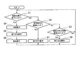
描画条件出しが完了し、生産が開始すると、図7に示すように、制御部8は、製造用の基板Kの交換が完了したか否かを判断し(ステップS1)、次いで、所定時間が経過したか否かを判断し(ステップS2)、さらに、製造用の基板Kが所定枚数塗布されたか否かを判断し(ステップS3)、ステップS1に処理を戻す。ここで、例えば、製造用の基板Kの交換完了は操作者による交換完了ボタン(入力部)の押下の有無や基板Kの載置完了を検出するセンサのオンオフ等に基づいて判断される。
When the drawing condition setting is completed and the production is started, as shown in FIG. 7, the
ステップS1で、条件出しに用いた基板が基板ステージ2上から搬出され、基板ステージ2に製造用の基板Kが搬入されて、製造用の基板Kの交換が完了したと判断した場合には(ステップS1のYES)、まず、各塗布ヘッド3A、3Bに清掃動作を実行させ(ステップS4)、次いで、各塗布ヘッド3A、3Bに捨て打ち動作を実行させ(ステップS5)、さらに、各塗布ヘッド3A、3B中の塗布実行対象の塗布ヘッドに塗布動作を実行させ(ステップS6)、処理をステップS1に戻す。ここで、清掃動作及び捨て打ち動作は製造用の基板Kが交換される毎に行われるように設定されているが、これに限るものではなく、例えば所定時間毎あるいは所定枚数毎に行われるように設定されてもよい。 When it is determined in step S1 that the substrate used for condition determination is unloaded from the substrate stage 2, the manufacturing substrate K is loaded onto the substrate stage 2, and the replacement of the manufacturing substrate K is completed ( In step S1, YES, first, the application heads 3A and 3B are caused to perform a cleaning operation (step S4), and then the application heads 3A and 3B are caused to perform a discarding operation (step S5). The coating operation of the coating execution target in 3A and 3B is caused to perform a coating operation (step S6), and the process returns to step S1. Here, the cleaning operation and the discarding operation are set to be performed every time the production substrate K is replaced, but the present invention is not limited to this. For example, it is performed every predetermined time or every predetermined number of sheets. May be set.
また、ステップS2で、所定時間が経過したと判断した場合には(ステップS2のYES)、各塗布ヘッド3A、3Bに捨て打ち動作を実行させ(ステップS7)、処理をステップS1に戻す。ここで、所定時間は例えば30秒であり、この所定時間は、次の基板Kが搬送されてこなかった場合などに捨て打ち動作を行うように設定されている。したがって、所定時間の経過は塗布後の基板Kの取り外し完了から計測される。 If it is determined in step S2 that the predetermined time has elapsed (YES in step S2), the application heads 3A and 3B are caused to perform a discarding operation (step S7), and the process returns to step S1. Here, the predetermined time is, for example, 30 seconds, and this predetermined time is set so that the discarding operation is performed when the next substrate K is not transported. Therefore, the passage of the predetermined time is measured from the completion of the removal of the substrate K after application.
また、ステップS3で、製造用の基板Kが所定枚数塗布されたと判断した場合には(ステップS3のYES)、各塗布ヘッド3A、3Bに捨て吐出動作を実行させ(ステップS8)、処理をステップS1に戻す。ここで、所定枚数は例えば30枚である。なお、捨て吐出動作は所定枚数毎に行われるように設定されているが、これに限るものではなく、例えば所定時間(例えば30分)毎に行われるように設定されてもよい。 If it is determined in step S3 that a predetermined number of production substrates K have been applied (YES in step S3), the application heads 3A and 3B are caused to perform a discarding discharge operation (step S8), and the process is performed. Return to S1. Here, the predetermined number is, for example, 30 sheets. The discard discharge operation is set to be performed every predetermined number of sheets, but is not limited thereto, and may be set to be performed every predetermined time (for example, 30 minutes), for example.
捨て打ちを行う場合、制御部8は、一対のY軸移動機構6A、6Bにより支持部材5をY軸方向に移動させ、X軸移動機構4により各塗布ヘッド3A、3BをX軸方向にそれぞれ移動させ、基板ステージ2上の捨て打ち基板Kaの各塗布開始位置にそれぞれ塗布実行対象、塗布実行非対象に関係なく各塗布ヘッド3A、3Bを対向させる。その後、制御部8は、塗布情報(吐出圧力、描画速度及びギャップなど)に基づいて、各塗布ヘッド3A、3Bの各々のノズル3bからペーストを吐出させながら、X軸移動機構4により各塗布ヘッド3A、3BをX軸方向に移動させ、基板ステージ2上の捨て打ち基板Kaの表面にペーストを塗布し、直線状あるいは枠形状のペーストパターンを形成する(図4参照)。これにより、捨て打ち基板Ka上にペーストパターンが形成されるので、そのペーストパターンを用いてペーストの検査を行うことが可能になり、さらに、固化状態あるいは軟化状態のペーストが吐出されて取り除かれるので、待機している塗布実行非対象の塗布ヘッドにおいてもペースト固化やペースト軟化による塗布性能の低下を防止することが可能になる。
When discarding, the
また、捨て吐出を行う場合には、制御部8は、X軸移動機構4により各塗布ヘッド3A、3BをX軸方向にそれぞれ移動させ、塗布ヘッド3Aを受け部材9aに対向させ、塗布ヘッド3Bを受け部材9bに対向させる。その後、制御部8は、塗布実行対象、塗布実行非対象に関係なく各塗布ヘッド3A、3Bの各々のノズル3bからそれぞれペーストを吐出させる。塗布ヘッド3Aから吐出されたペーストは受け部材9a上に溜まり、塗布ヘッド3Bから吐出されたペーストは受け部材9b上に溜まる(図5参照)。これにより、強固化状態のペーストが吐出されて取り除かれるので、ペースト固化による塗布性能の低下を防止することが可能になる。
Further, when performing the discard discharge, the
また、清掃(ノズルクリーニング)を行う場合には、制御部8は、X軸移動機構4により塗布実行対象、塗布実行非対象に関係なく各塗布ヘッド3A、3BをX軸方向にそれぞれ移動させ、塗布ヘッド3Aを清掃部材10aに対向させ、塗布ヘッド3Bを清掃部材10bに対向させる。その後、制御部8は、各YZ軸移動機構3cにより各塗布ヘッド3A、3BをZ軸方向にそれぞれ移動させ、塗布ヘッド3Aのノズル3bを清掃部材10aに接触させ、塗布ヘッド3Bのノズル3bを清掃部材10bに接触させる(図6参照)。これにより、各ノズル3bの先端に付着して残った余分なペーストが取り除かれ、各ノズル3bがクリーニングされるので、ノズル3bに付着したペーストに起因する塗布性能の低下を防止することが可能になる。
When performing cleaning (nozzle cleaning), the
また、塗布を行う場合には、制御部8は、各塗布ヘッド3A、3Bの中から塗布実行対象の塗布ヘッドを選択し、一対のY軸移動機構6A、6Bにより支持部材5をY軸方向に移動させ、X軸移動機構4により塗布実行対象の塗布ヘッドをX軸方向に移動させ、基板ステージ2上の製造用の基板Kの塗布開始位置に塗布実行対象の塗布ヘッドを対向させる。その後、制御部8は、描画条件である塗布情報(吐出圧力、描画速度及びギャップなど)に基づいて、塗布実行対象の塗布ヘッドのノズル3bからペーストを吐出させながら、一対のY軸移動機構6A、6Bにより支持部材5をY軸方向に移動させ、X軸移動機構4により塗布実行対象の塗布ヘッドをX軸方向に移動させ、基板ステージ2上の製造用の基板Kの表面にペーストを塗布し、所定枠形状のペーストパターンを形成する。
When performing application, the
ここで、面取り数が1である場合には、塗布ヘッド3Aが塗布実行対象の塗布ヘッドとして塗布動作を行う(図2参照)。このとき、塗布実行非対象の塗布ヘッド3Bは、製造用の基板Kに対向しない待機位置(例えば、塗布ヘッド3Bが受け部材9bあるいは清掃部材10bに対向する位置)で待機する(図1参照)。一方、面取り数が2である場合には、各塗布ヘッド3A、3Bが塗布実行対象の塗布ヘッドとして塗布動作を行う(図3参照)。なお、サックバック動作は塗布動作中にも行われ、さらに、捨て打ち動作及び捨て吐出動作後にも行われる。このサックバック動作によりペースト垂れに加え、ノズル3bの汚れを防止することが可能になる。
Here, when the number of chamfers is 1, the
このような製造工程では、各塗布ヘッド3A、3Bは、前述のように所定のタイミングで、面取り数に関係なく、すなわち塗布実行対象あるいは塗布実行非対象であるかに関係なく維持動作(捨て打ち動作、捨て吐出動作、清掃動作及びサックバック動作など)を行う。したがって、面取り数が1である場合でも、塗布実行対象の塗布ヘッドである塗布ヘッド3Aだけでなく、その塗布ヘッド3Aに加え、塗布実行非対象の塗布ヘッドである塗布ヘッド3Bも維持動作を行う。つまり、各塗布ヘッド3A、3Bは、塗布実行対象であるか否かに関係なく維持動作を同時に行うことになる。
In such a manufacturing process, each of the coating heads 3A and 3B is maintained at a predetermined timing as described above regardless of the number of chamfers, that is, regardless of whether the coating is performed or not performed. Operation, disposal discharge operation, cleaning operation, suck back operation, etc.). Therefore, even when the number of chamfers is 1, not only the
その後、段取り替えの際にパネルサイズが変更され、面取り数が2に設定された場合でも、前回、塗布実行非対象の塗布ヘッドである塗布ヘッド3Bの塗布性能は、塗布実行対象の塗布ヘッド3Aと同じように良好に維持されているので、今回、そのまま塗布ヘッド3Bを塗布実行対象の塗布ヘッドとして用いることが可能である。また、各塗布ヘッド3A、3Bでの描画条件出しは生産開始前に一度行われているので、面取り数が2に変更された場合に描画条件出しを再度行う必要は生じない。したがって、パネルサイズ及び面取り数が変更される場合でも、従来のように、塗布ヘッドの取り付けあるいは取り外しを行う必要がなくなり、さらに、それらの変更の度に描画条件出しを行う必要がなくなるので、段取り替え時間を短縮することが可能になり、生産性を向上させることができる。特に、段取り替え時間の短縮として、描画条件出しの際の塗布量調整を行う場合、塗布されたペーストの塗布量を測定する塗布量測定器を増やして複数のペーストパターンを同時に測定したり、繋ぎ検査を行う場合、画像処理装置を増やしたりすることもなくなるので、各機器の取り付けスペースを確保する必要がなくなり、加えて、装置価格が上昇することも抑えられる。
Thereafter, even when the panel size is changed at the time of setup change and the number of chamfers is set to 2, the coating performance of the
以上説明したように、本発明の実施の形態によれば、各塗布ヘッド3A、3B中の塗布実行対象の塗布ヘッド3Aに対して維持動作を実行させる場合、それらの塗布ヘッド3A、3B中の塗布実行非対象の塗布ヘッド3Bに対しても維持動作を実行させることによって、段取り替えの際にパネルサイズ及び面取り数が変更された場合でも、前回、塗布実行非対象の塗布ヘッド3Bの塗布性能は塗布実行対象の塗布ヘッド3Aと同じように良好に維持されているので、今回、そのまま塗布ヘッド3Bを塗布実行対象の塗布ヘッドとして用いることが可能である。これにより、パネルサイズ及び面取り数が変更される場合でも、従来のように塗布ヘッドの取り付けあるいは取り外しを行う必要がなくなり、さらに、それらの変更の度に描画条件出しを行う必要がなくなるので、段取り替え時間を短縮することが可能になり、生産性を向上させることができる。加えて、段取り替え時間の短縮として、描画条件出しの際の塗布量調整を行う場合、塗布量測定器を増やして複数のペーストパターンを同時に測定したり、繋ぎ検査を行う場合、画像処理装置を増やしたりする必要もなくなるので、各機器の取り付けスペースを確保することなく、装置価格の上昇を抑えることができる。その結果、機器追加及び価格上昇を抑えつつ、段取り替え時間の短縮により生産性を向上させることができる。
As described above, according to the embodiment of the present invention, when the maintenance operation is performed on the
従来、面取り数の変更差が大きくなるほど、段取り替え時間は長くなる傾向にあるが(例えば、面取り数の変更差が1より4の方が塗布ヘッドの取り付けあるいは取り外し時間及び描画条件出し時間が長くなるため、段取り替え時間は長くなる)、あらかじめ最大面取り数に合わせた数の塗布ヘッドを取り付けておき、塗布実行対象の塗布ヘッドの数が塗布ヘッドの総数よりも少ないときでも、前述のように塗布実行対象の塗布ヘッドに加え、塗布実行対象以外の塗布ヘッド(塗布実行非対象の塗布ヘッド)も維持動作を行うようにすれば、塗布実行対象以外の塗布ヘッドの塗布性能も塗布実行対象の塗布ヘッドと同等に維持されるので、その後に面取り数が大きく増加した場合でも、塗布実行対象以外の塗布ヘッドをそのまま塗布実行対象の塗布ヘッドして用いることが可能である。これにより、段取り替え時間の短縮を実現することができる。特に、面取り数の変更差が大きくなるほど、従来の段取り替え時間は長くなるため、その段取り替え時間の短縮効果が向上する。これにより、生産性を向上させることが可能となる。 Conventionally, as the change difference in the number of chamfers increases, the setup change time tends to be longer (for example, when the change difference in the number of chamfers is 1, the time for attaching or removing the coating head and the drawing condition setting time are longer). Therefore, even if the number of coating heads corresponding to the maximum chamfering number is attached in advance and the number of coating heads to be coated is smaller than the total number of coating heads, as described above In addition to the application execution target application heads, if the application heads other than the application execution target (application heads not subject to application execution) are also maintained, the application performance of the application heads other than the application execution targets can be Since it is maintained at the same level as the application head, even if the number of chamfers increases afterwards, the application heads other than the application execution target remain as application execution targets. It can be used by coating head. Thereby, shortening of setup change time is realizable. In particular, as the change difference in the number of chamfers increases, the conventional setup change time becomes longer, so that the effect of shortening the setup change time is improved. Thereby, productivity can be improved.
また、各塗布ヘッド3A、3Bを支持する支持部材5と、その支持部材5の両端部を支持して支持部材5を移動させる一対のY軸移動機構6A、6Bと、各塗布ヘッド3A、3Bを支持部材5に沿って移動させるX軸移動機構4と、支持部材5と共に移動可能に支持部材5の両端部にそれぞれ複数の受け部材9a、9bとを設け、塗布実行対象の塗布ヘッド及び塗布実行非対象の塗布ヘッドをそれぞれ各受け部材9a、9bに対向させ、それらの塗布ヘッドに捨て吐出動作を実行させることから、各受け部材9a、9bを塗布ヘッドに対向する位置まで移動させる移動機構を設ける必要はなく、各塗布ヘッド3A、3Bを移動させるX軸移動機構4を共用することが可能になるので、装置の複雑化及び装置価格の上昇を抑えることができる。さらに、支持部材5と共に移動可能に支持部材5の両端部にそれぞれ複数の清掃部材10a、10bを設け、塗布実行対象の塗布ヘッド及び塗布実行非対象の塗布ヘッドをそれぞれ各清掃部材10a、10bに対向させ、それらの塗布ヘッドに清掃動作を実行させることから、各清掃部材10a、10bを塗布ヘッドに対向する位置まで移動させる移動機構を設ける必要はなく、各塗布ヘッド3A、3Bを移動させるX軸移動機構4を共用することが可能になるので、装置の複雑化及び装置価格の上昇をより抑えることができる。
Also, a
また、待機位置に受け部材9a、9bと清掃部材10a、10bを設けたので、塗布実行対象の塗布ヘッドが塗布中であっても維持動作を行うことが可能である。したがって、塗布実行対象の塗布ヘッドが基板Kに対してペーストを塗布描画している期間内に、塗布実行非対象の塗布ヘッドによって受け部材9a、9bに対する捨て吐出動作を予め設定した時間を経過する毎に実行するようにしてもよい。
Further, since the receiving
(他の実施の形態)
なお、本発明は、前述の実施の形態に限るものではなく、その要旨を逸脱しない範囲において種々変更可能である。
(Other embodiments)
The present invention is not limited to the above-described embodiment, and various modifications can be made without departing from the scope of the invention.
例えば、前述の実施の形態においては、2つの塗布ヘッド3A、3Bを支持部材5にそれぞれ設けているが、これに限るものではなく、3つの塗布ヘッドを支持部材5にそれぞれ設けるようにしてもよく、その数は限定されない。
For example, in the above-described embodiment, the two
また、前述の実施の形態においては、1つの支持部材5を設けているが、これに限るものではなく、2つの支持部材5を設けるようにしてもよく、その数は限定されない。なお、2つの支持部材5には、例えば、それぞれ複数の塗布ヘッドが設けられてもよい。
In the embodiment described above, one
さらに、前述の実施の形態においては、ペーストとしてシール性及び接着性を有するシール剤を用いているが、必ずしもシール性及び接着性を有する必要はなく、シール性及び接着性のいずれか一方のみを有するペースト等、他の性状を有するペーストを用いるようにしてもよい。 Furthermore, in the above-described embodiment, a sealing agent having a sealing property and an adhesive property is used as a paste. However, it is not always necessary to have a sealing property and an adhesive property, and only one of the sealing property and the adhesive property is used. You may make it use the paste which has other characteristics, such as the paste which has.
加えて、前述の実施の形態においては、基板ステージ2を架台7上に固定し、各塗布ヘッド3A、3B及び支持部材5を移動させて、基板Kの表面にペーストを塗布しているが、これに限るものではなく、基板ステージ2をY軸方向やX軸方向、θ方向(X軸及びY軸を含む平面での回転方向)等に移動可能に構成するようにしてもよく、例えば、基板ステージ2を支持部材5の移動方向(Y軸方向)と同じ方向に移動可能に構成してもよい。この場合には、基板Kと各塗布ヘッド3A、3BとをY軸方向に相対移動させるときに、基板ステージ2と支持部材5とを互いに相反する方向に移動させれば、支持部材5のみの移動を行う場合に比べて、基板ステージ2及び支持部材5の移動速度を半分にすることができる。このため、基板ステージ2及び支持部材5の移動に伴う慣性力が小さくなるので、基板ステージ2及び支持部材5の加速あるいは減速に起因して生じる振動を低減させることができる。その結果、Y軸方向に沿うペーストパターンの始端及び終端の形状や塗布方向が転換するペーストパターンのコーナー部の形状を所望の形状で精度良く塗布することが可能となり、品質の良い液晶表示パネルを製造することができる。
In addition, in the above-described embodiment, the substrate stage 2 is fixed on the
最後に、前述の実施の形態においては、各種の数値を挙げているが、それらの数値は例示であり、限定されるものではない。 Finally, in the above-described embodiment, various numerical values are given, but these numerical values are merely examples and are not limited.
1 ペースト塗布装置
3A、3B 塗布ヘッド
9a、9b 受け部材
10a、10b 清掃部材
K 塗布対象物(基板)
Ka 捨て打ち用の塗布対象物(捨て打ち基板)
DESCRIPTION OF
Ka Disposal object to be thrown away (discarded substrate)
Claims (10)
前記複数の塗布ヘッドの前記塗布動作及び前記維持動作を制御する制御部と、を備え、
前記制御部は、
前記複数の塗布ヘッド中の塗布実行対象の塗布ヘッドに対して前記塗布動作を実行させ、
前記塗布実行対象の塗布ヘッドに対して前記維持動作を実行させるとき、前記複数の塗布ヘッド中の塗布実行非対象の塗布ヘッドに対しても前記維持動作を実行させることを特徴とするペースト塗布装置。 A plurality of coating heads for performing a coating operation for discharging and applying a paste to a coating object and a maintenance operation for maintaining the coating performance;
A controller for controlling the application operation and the maintenance operation of the plurality of application heads,
The controller is
Causing the coating operation to be performed on a coating head to be coated among the plurality of coating heads,
When the maintenance operation is performed on the coating execution target coating head, the maintenance operation is also performed on the coating execution non-target coating heads in the plurality of coating heads. .
前記維持動作は、前記塗布ヘッドを移動させて前記清掃部材に対向させた後、前記塗布ヘッドのノズルを前記清掃部材に接触させることにより清掃する清掃動作であることを特徴とする請求項1記載のペースト塗布装置。 A cleaning member for cleaning the application head;
2. The cleaning operation according to claim 1, wherein the maintaining operation is a cleaning operation in which the application head is moved to face the cleaning member and then cleaned by bringing a nozzle of the application head into contact with the cleaning member. Paste applicator.
前記塗布実行対象の塗布ヘッドに対して前記維持動作を実行させる工程と、
前記塗布実行対象の塗布ヘッドに対して前記維持動作を実行させるとき、前記複数の塗布ヘッド中の塗布実行非対象の塗布ヘッドに対しても前記維持動作を実行させる工程と、
を有することを特徴とするペースト塗布方法。 A step of performing the coating operation on the coating execution target coating heads in a plurality of coating heads, each performing a coating operation for discharging and applying a paste to a coating target and a maintenance operation for maintaining coating performance;
A step of causing the maintenance operation to be performed on the coating head to be coated,
A step of causing the maintenance operation to be performed on a non-application-execution application head in the plurality of application heads when the maintenance operation is executed on the application-execution application head;
A paste coating method characterized by comprising:
Priority Applications (4)
| Application Number | Priority Date | Filing Date | Title |
|---|---|---|---|
| JP2008179086A JP5288917B2 (en) | 2008-07-09 | 2008-07-09 | Paste coating apparatus and paste coating method |
| TW098122310A TWI417144B (en) | 2008-07-09 | 2009-07-01 | Paste coating apparatus and paste coating method |
| KR1020090061242A KR101078902B1 (en) | 2008-07-09 | 2009-07-06 | Apparatus for applying paste and method of applying paste |
| CN2009101584841A CN101623683B (en) | 2008-07-09 | 2009-07-08 | Device and method for coating with paste |
Applications Claiming Priority (1)
| Application Number | Priority Date | Filing Date | Title |
|---|---|---|---|
| JP2008179086A JP5288917B2 (en) | 2008-07-09 | 2008-07-09 | Paste coating apparatus and paste coating method |
Publications (3)
| Publication Number | Publication Date |
|---|---|
| JP2010017629A JP2010017629A (en) | 2010-01-28 |
| JP2010017629A5 JP2010017629A5 (en) | 2011-08-25 |
| JP5288917B2 true JP5288917B2 (en) | 2013-09-11 |
Family
ID=41519761
Family Applications (1)
| Application Number | Title | Priority Date | Filing Date |
|---|---|---|---|
| JP2008179086A Active JP5288917B2 (en) | 2008-07-09 | 2008-07-09 | Paste coating apparatus and paste coating method |
Country Status (4)
| Country | Link |
|---|---|
| JP (1) | JP5288917B2 (en) |
| KR (1) | KR101078902B1 (en) |
| CN (1) | CN101623683B (en) |
| TW (1) | TWI417144B (en) |
Families Citing this family (13)
| Publication number | Priority date | Publication date | Assignee | Title |
|---|---|---|---|---|
| US8646507B2 (en) * | 2009-09-04 | 2014-02-11 | Dexerials Corporation | Charging apparatus |
| JP5861166B2 (en) * | 2011-06-09 | 2016-02-16 | 株式会社ブイ・テクノロジー | Dispenser device, pattern defect correcting device, and method for eliminating clogging of dispenser |
| CN102411233B (en) * | 2011-11-23 | 2013-10-16 | 深圳市华星光电技术有限公司 | Device and method for coating seal on liquid crystal substrate |
| US9475078B2 (en) * | 2012-10-29 | 2016-10-25 | Illinois Tool Works Inc. | Automated multiple head cleaner for a dispensing system and related method |
| JP2015142905A (en) * | 2013-12-25 | 2015-08-06 | 芝浦メカトロニクス株式会社 | Adhesive application device, cleaning method of adhesive application member, display panel manufacturing apparatus, and manufacturing method of display panel |
| KR102341945B1 (en) * | 2017-03-13 | 2021-12-22 | 주식회사 탑 엔지니어링 | Substrate processing apparatus |
| KR102213687B1 (en) | 2017-05-25 | 2021-02-05 | 무사시 엔지니어링 가부시키가이샤 | Liquid material application apparatus and liquid material application method |
| KR102449702B1 (en) * | 2017-12-13 | 2022-09-30 | 세메스 주식회사 | Apparatus for Droplet Formation and Method for Droplet Formation |
| JP6982731B2 (en) * | 2018-01-31 | 2021-12-17 | パナソニックIpマネジメント株式会社 | Paste application device and paste application method |
| JP7012213B2 (en) * | 2018-01-31 | 2022-01-28 | パナソニックIpマネジメント株式会社 | Paste application device and paste application method |
| KR101970444B1 (en) * | 2018-12-14 | 2019-04-18 | 문득수 | Resin dispenser for display panel with dual type of unidirectional and bidirectional, and resin dispensing using the same |
| JP6990927B2 (en) * | 2019-01-21 | 2022-01-12 | 武蔵エンジニアリング株式会社 | Liquid material coating device and liquid material coating method |
| CN112477401B (en) * | 2020-12-21 | 2023-10-20 | 四川锐坤电子技术有限公司 | Pad printing equipment |
Family Cites Families (13)
| Publication number | Priority date | Publication date | Assignee | Title |
|---|---|---|---|---|
| US4157149A (en) * | 1977-10-31 | 1979-06-05 | Moen Lenard E | Multiple nozzle fluid dispenser for complex fluid delivery patterns |
| JPH0725967U (en) * | 1993-10-26 | 1995-05-16 | 日立テクノエンジニアリング株式会社 | Paste applicator |
| JP3022855B1 (en) * | 1998-11-26 | 2000-03-21 | 埼玉日本電気株式会社 | Needle hardening prevention mechanism of coating equipment |
| JP2003519026A (en) * | 1999-12-30 | 2003-06-17 | アクゾ ノベル エヌ.ヴィー. | Bonding method and apparatus therefor |
| JP3993496B2 (en) * | 2001-09-27 | 2007-10-17 | 東京エレクトロン株式会社 | Substrate processing method and coating processing apparatus |
| JP2004014393A (en) * | 2002-06-10 | 2004-01-15 | Dainippon Printing Co Ltd | Phosphor screen forming method and phosphor screen forming device of plasma display panel |
| JP2004090264A (en) * | 2002-08-29 | 2004-03-25 | Canon Inc | Inkjet recorder and its controlling method and program |
| CN2705239Y (en) * | 2003-09-28 | 2005-06-22 | 汕头市远东轻化装备有限公司 | Sizing composite device of composite coating machine |
| TW200638083A (en) * | 2005-04-18 | 2006-11-01 | Shibaura Mechatronics Corp | The coating apparatus and method thereof |
| TWM287028U (en) * | 2005-10-17 | 2006-02-01 | All Ring Tech Co Ltd | Multiplexing dispenser |
| JP4893016B2 (en) * | 2006-02-17 | 2012-03-07 | 株式会社日立プラントテクノロジー | Paste applicator |
| JP2007289796A (en) * | 2006-04-20 | 2007-11-08 | Yamaha Motor Co Ltd | Coating apparatus |
| KR100778147B1 (en) * | 2006-12-13 | 2007-11-21 | 주식회사 탑 엔지니어링 | Dispensing apparatus for manufacturing liquid display panel |
-
2008
- 2008-07-09 JP JP2008179086A patent/JP5288917B2/en active Active
-
2009
- 2009-07-01 TW TW098122310A patent/TWI417144B/en active
- 2009-07-06 KR KR1020090061242A patent/KR101078902B1/en active IP Right Grant
- 2009-07-08 CN CN2009101584841A patent/CN101623683B/en active Active
Also Published As
| Publication number | Publication date |
|---|---|
| KR20100006541A (en) | 2010-01-19 |
| CN101623683A (en) | 2010-01-13 |
| CN101623683B (en) | 2012-10-10 |
| JP2010017629A (en) | 2010-01-28 |
| TW201006566A (en) | 2010-02-16 |
| TWI417144B (en) | 2013-12-01 |
| KR101078902B1 (en) | 2011-11-01 |
Similar Documents
| Publication | Publication Date | Title |
|---|---|---|
| JP5288917B2 (en) | Paste coating apparatus and paste coating method | |
| JP4490797B2 (en) | Substrate processing equipment | |
| JPH1133458A (en) | Liquid body coating device | |
| JP5240069B2 (en) | Screen printing mask cleaning apparatus, screen printing machine, and screen printing mask cleaning method | |
| JP6111429B2 (en) | Viscous body coating method and viscous body coating apparatus | |
| TW201236774A (en) | Sweeping member, sweeping method of coater, and manufacturing method of sweeping device and display member | |
| TWI397755B (en) | Apparatus and method for dropping liquid crystals | |
| JP6475030B2 (en) | Substrate processing system and substrate processing method | |
| KR20100012950A (en) | Method for counting the number of liquid crytal droplet | |
| JP5377899B2 (en) | Paste applicator | |
| JP2017191798A (en) | Electronic component mounting apparatus and dispenser | |
| JP2009022845A (en) | Apparatus for discharging liquid droplet, weight measurement method and discharging method of liquid object | |
| JP2008238143A (en) | Liquid droplet delivery apparatus and method for replacing liquid droplet delivery head | |
| JP6194200B2 (en) | Screen printing apparatus and cleaning processing apparatus | |
| JP6318035B2 (en) | Printing apparatus and solder recovery method for printing apparatus | |
| KR100663643B1 (en) | Liquid Crystal Dispensing Device | |
| JP2006231288A (en) | Method and apparatus for cleaning coating head, paste coating method and apparatus, and method and apparatus for producing plasma display member | |
| JP4566859B2 (en) | Coating processing equipment | |
| JP2008104947A (en) | Coating machine and control method | |
| JP2016082085A (en) | Electronic component mounting device | |
| JP2012106203A (en) | Method for forming coating film to substrate | |
| KR101972930B1 (en) | Apparatus fdr treating substrates | |
| CN108430777B (en) | Printing apparatus and printing method | |
| JP5246122B2 (en) | Coating liquid coating method, plasma display member manufacturing method, and coating liquid coating apparatus | |
| JP5423917B2 (en) | Method for measuring discharge weight of droplet discharge device and droplet discharge device |
Legal Events
| Date | Code | Title | Description |
|---|---|---|---|
| A521 | Written amendment |
Free format text: JAPANESE INTERMEDIATE CODE: A523 Effective date: 20110711 |
|
| A621 | Written request for application examination |
Free format text: JAPANESE INTERMEDIATE CODE: A621 Effective date: 20110711 |
|
| A977 | Report on retrieval |
Free format text: JAPANESE INTERMEDIATE CODE: A971007 Effective date: 20130314 |
|
| A131 | Notification of reasons for refusal |
Free format text: JAPANESE INTERMEDIATE CODE: A131 Effective date: 20130319 |
|
| A521 | Written amendment |
Free format text: JAPANESE INTERMEDIATE CODE: A523 Effective date: 20130510 |
|
| TRDD | Decision of grant or rejection written | ||
| A01 | Written decision to grant a patent or to grant a registration (utility model) |
Free format text: JAPANESE INTERMEDIATE CODE: A01 Effective date: 20130528 |
|
| A61 | First payment of annual fees (during grant procedure) |
Free format text: JAPANESE INTERMEDIATE CODE: A61 Effective date: 20130604 |
|
| R150 | Certificate of patent or registration of utility model |
Ref document number: 5288917 Country of ref document: JP Free format text: JAPANESE INTERMEDIATE CODE: R150 |