JP5263312B2 - Traffic jam judging device and vehicle control device - Google Patents
Traffic jam judging device and vehicle control device Download PDFInfo
- Publication number
- JP5263312B2 JP5263312B2 JP2011022019A JP2011022019A JP5263312B2 JP 5263312 B2 JP5263312 B2 JP 5263312B2 JP 2011022019 A JP2011022019 A JP 2011022019A JP 2011022019 A JP2011022019 A JP 2011022019A JP 5263312 B2 JP5263312 B2 JP 5263312B2
- Authority
- JP
- Japan
- Prior art keywords
- vehicle
- section
- travel
- traveling
- information
- Prior art date
- Legal status (The legal status is an assumption and is not a legal conclusion. Google has not performed a legal analysis and makes no representation as to the accuracy of the status listed.)
- Active
Links
Images


Classifications
-
- G—PHYSICS
- G08—SIGNALLING
- G08G—TRAFFIC CONTROL SYSTEMS
- G08G1/00—Traffic control systems for road vehicles
-
- G—PHYSICS
- G08—SIGNALLING
- G08G—TRAFFIC CONTROL SYSTEMS
- G08G1/00—Traffic control systems for road vehicles
- G08G1/01—Detecting movement of traffic to be counted or controlled
- G08G1/0104—Measuring and analyzing of parameters relative to traffic conditions
- G08G1/0108—Measuring and analyzing of parameters relative to traffic conditions based on the source of data
- G08G1/0112—Measuring and analyzing of parameters relative to traffic conditions based on the source of data from the vehicle, e.g. floating car data [FCD]
-
- G—PHYSICS
- G08—SIGNALLING
- G08G—TRAFFIC CONTROL SYSTEMS
- G08G1/00—Traffic control systems for road vehicles
- G08G1/01—Detecting movement of traffic to be counted or controlled
- G08G1/0104—Measuring and analyzing of parameters relative to traffic conditions
-
- G—PHYSICS
- G08—SIGNALLING
- G08G—TRAFFIC CONTROL SYSTEMS
- G08G1/00—Traffic control systems for road vehicles
- G08G1/01—Detecting movement of traffic to be counted or controlled
- G08G1/0104—Measuring and analyzing of parameters relative to traffic conditions
- G08G1/0125—Traffic data processing
- G08G1/0133—Traffic data processing for classifying traffic situation
-
- G—PHYSICS
- G08—SIGNALLING
- G08G—TRAFFIC CONTROL SYSTEMS
- G08G1/00—Traffic control systems for road vehicles
- G08G1/01—Detecting movement of traffic to be counted or controlled
- G08G1/0104—Measuring and analyzing of parameters relative to traffic conditions
- G08G1/0137—Measuring and analyzing of parameters relative to traffic conditions for specific applications
- G08G1/0145—Measuring and analyzing of parameters relative to traffic conditions for specific applications for active traffic flow control
-
- G—PHYSICS
- G08—SIGNALLING
- G08G—TRAFFIC CONTROL SYSTEMS
- G08G1/00—Traffic control systems for road vehicles
- G08G1/09—Arrangements for giving variable traffic instructions
- G08G1/0962—Arrangements for giving variable traffic instructions having an indicator mounted inside the vehicle, e.g. giving voice messages
- G08G1/0967—Systems involving transmission of highway information, e.g. weather, speed limits
- G08G1/096708—Systems involving transmission of highway information, e.g. weather, speed limits where the received information might be used to generate an automatic action on the vehicle control
- G08G1/096725—Systems involving transmission of highway information, e.g. weather, speed limits where the received information might be used to generate an automatic action on the vehicle control where the received information generates an automatic action on the vehicle control
-
- G—PHYSICS
- G08—SIGNALLING
- G08G—TRAFFIC CONTROL SYSTEMS
- G08G1/00—Traffic control systems for road vehicles
- G08G1/09—Arrangements for giving variable traffic instructions
- G08G1/0962—Arrangements for giving variable traffic instructions having an indicator mounted inside the vehicle, e.g. giving voice messages
- G08G1/0967—Systems involving transmission of highway information, e.g. weather, speed limits
- G08G1/096733—Systems involving transmission of highway information, e.g. weather, speed limits where a selection of the information might take place
- G08G1/09675—Systems involving transmission of highway information, e.g. weather, speed limits where a selection of the information might take place where a selection from the received information takes place in the vehicle
-
- G—PHYSICS
- G08—SIGNALLING
- G08G—TRAFFIC CONTROL SYSTEMS
- G08G1/00—Traffic control systems for road vehicles
- G08G1/09—Arrangements for giving variable traffic instructions
- G08G1/0962—Arrangements for giving variable traffic instructions having an indicator mounted inside the vehicle, e.g. giving voice messages
- G08G1/0967—Systems involving transmission of highway information, e.g. weather, speed limits
- G08G1/096766—Systems involving transmission of highway information, e.g. weather, speed limits where the system is characterised by the origin of the information transmission
- G08G1/096775—Systems involving transmission of highway information, e.g. weather, speed limits where the system is characterised by the origin of the information transmission where the origin of the information is a central station
-
- G—PHYSICS
- G08—SIGNALLING
- G08G—TRAFFIC CONTROL SYSTEMS
- G08G1/00—Traffic control systems for road vehicles
- G08G1/09—Arrangements for giving variable traffic instructions
- G08G1/0962—Arrangements for giving variable traffic instructions having an indicator mounted inside the vehicle, e.g. giving voice messages
- G08G1/0967—Systems involving transmission of highway information, e.g. weather, speed limits
- G08G1/096766—Systems involving transmission of highway information, e.g. weather, speed limits where the system is characterised by the origin of the information transmission
- G08G1/096791—Systems involving transmission of highway information, e.g. weather, speed limits where the system is characterised by the origin of the information transmission where the origin of the information is another vehicle
Description
本発明は、渋滞判定装置、及び車両制御装置に関するものである。 The present invention relates to a traffic jam determination device and a vehicle control device.
従来、交通情報や走行パターンに応じて渋滞を判断し、その判断結果に基づいて車両を走行させる車両制御装置が知られている。例えば、下記の特許文献1に記載の車両制御装置では、渋滞情報又は走行パターンによって渋滞長を算出し、渋滞長が所定以上の場合に、車両の自動運転を行っている。
2. Description of the Related Art Conventionally, there is known a vehicle control device that determines a traffic jam according to traffic information and a driving pattern and drives the vehicle based on the determination result. For example, in the vehicle control device described in
しかしながら、上記特許文献1に記載の車両制御装置は、交通情報の遅延や走行パターンの誤判定などにより、十分な精度で渋滞を判断することができなかった。また、上記特許文献1に記載の車両制御装置は、渋滞長に基づいて車両の自動運転を行うか否かを判断しているため、渋滞内の様々な車両の走行状態に適応することができなかった。
However, the vehicle control device described in
そこで本発明は、このような問題点を解決するためになされたものであって、渋滞内の車両の走行状態を精度よく判定し、渋滞内の車両の走行状態に応じて車両の走行制御を行うことを可能とする渋滞判定装置、及び車両制御装置を提供することを目的とする。 Accordingly, the present invention has been made to solve such a problem, and accurately determines the traveling state of a vehicle in a traffic jam and performs vehicle travel control according to the traveling status of the vehicle in the traffic jam. It is an object of the present invention to provide a congestion determination device and a vehicle control device that can be performed.
上記課題を解決するため、本発明に係る渋滞判定装置は、複数の車両の走行状態に関する走行情報を取得する走行情報取得手段と、走行情報取得手段により取得された複数の車両の走行情報を解析し、車両が減速傾向を示す末尾区間、車両が安定した速度変動を示す中心区間、及び、車両が加速傾向を示す回復区間を含む少なくとも3つの区間に、渋滞区間を分類する走行情報解析手段と、走行情報取得手段により取得された複数の車両の現在の走行情報に基づいて、複数の車両の各々が少なくとも3つの区間のいずれの区間を走行中であるかを判定する走行区間判定手段と、を備える。走行情報解析手段は、車両の速度に関する多変量解析を行うことで、渋滞区間を少なくとも3つの区間に分類する。 To solve the above problems, traffic congestion detection apparatus according to the present invention, analysis and traveling information acquiring means for acquiring traveling information relating to the running states of a plurality of vehicles, travel information of a plurality of vehicle acquired by the travel information acquisition unit And a travel information analyzing means for classifying the congestion section into at least three sections including a tail section where the vehicle shows a deceleration tendency, a central section where the vehicle shows a stable speed fluctuation, and a recovery section where the vehicle shows an acceleration tendency. , based on the current travel information of a plurality of vehicle acquired by the travel information acquisition unit, a traveling zone determination means for determining whether the vehicle is traveling any section between each of the plurality of vehicles are at least three wards . The travel information analysis means classifies the traffic jam section into at least three sections by performing multivariate analysis on the vehicle speed.
本発明では、車両の走行状態に基づいて、渋滞区間を少なくとも3つの区間に分類できることを見出した。そして本発明によれば、現在の走行情報に基づいて、車両が少なくとも3つの区間のうちいずれの区間を走行中であるかを判定することによって、車両が現在走行していると判定された区間により、車両がどのような走行状態であるか推測できる。さらに、例えば、渋滞区間内の走行区間に応じて適切な運転支援を行う等、渋滞区間内の走行区間に応じた制御を行うことが可能となる。その結果、車両の燃費向上を実現することが可能となる。 In the present invention, it has been found that the traffic jam section can be classified into at least three sections based on the running state of the vehicle. According to the present invention, the section in which the vehicle is currently traveling is determined by determining which section of the at least three sections the vehicle is traveling based on the current traveling information. Thus, it can be estimated what traveling state the vehicle is in. Further, for example, it is possible to perform control according to the travel section in the traffic jam section, such as performing appropriate driving support according to the travel section in the traffic jam section. As a result, it is possible to improve the fuel efficiency of the vehicle.
また、複数の車両の走行情報に基づいて、車両の走行区間を判定することができ、より高い精度で判定することが可能となる。 Further , the travel section of the vehicle can be determined based on the travel information of the plurality of vehicles, and determination can be made with higher accuracy.
また、複数の走行情報に基づいて、渋滞区間を少なくとも3つの区間に分類することで、分類の精度を向上でき、車両が渋滞区間のどの区間を現在走行しているかをより精度よく判定することができる。 Also , by classifying a traffic jam section into at least three sections based on a plurality of travel information, the accuracy of classification can be improved, and which section of the traffic jam section the vehicle is currently traveling in can be determined more accurately. Can do.
また、車両の速度に関する多変量解析により、分類の精度を向上でき、車両が渋滞区間のどの区間を現在走行しているかをより精度よく判定することができる。 Further , the multivariate analysis on the speed of the vehicle can improve the classification accuracy, and it is possible to more accurately determine which section of the congestion section the vehicle is currently traveling.
また、渋滞区間を末尾区間、中心区間、回復区間に分類することで、各区間における車両の挙動(走行状態)に応じて適切な運転支援を行う等、各区間に応じた制御を行うことが可能となる。その結果、車両のさらなる燃費向上を実現することが可能となる。 In addition , by classifying the congestion section into the end section, the center section, and the recovery section, it is possible to perform control according to each section, such as providing appropriate driving support according to the behavior (running state) of the vehicle in each section. It becomes possible. As a result, it is possible to realize further improvement in fuel consumption of the vehicle.
また本発明に係る車両制御装置は、上記渋滞判定装置と、走行区間判定手段の判定結果に基づいて車両の運転支援を行う運転支援手段と、を備えることを特徴とする。これによれば、渋滞区間内の走行区間に応じて適切な運転支援を行うことができる。その結果、車両のさらなる燃費向上を実現することが可能となる。 The vehicle control device according to the present invention is characterized by comprising the above-described traffic jam determination device and driving support means for supporting driving of the vehicle based on the determination result of the travel section determination means. According to this, appropriate driving assistance can be performed according to the travel section in the traffic jam section. As a result, it is possible to realize further improvement in fuel consumption of the vehicle.
また本発明に係る車両制御装置において、他車両の走行状態に関する走行情報を取得する他車両情報取得手段と、他車両情報取得手段により取得された他車両の走行情報と解析手段による解析結果とに基づいて、他車両が渋滞区間を走行中であるか否かを判定する他車両走行区間判定手段と、をさらに備えてもよく、運転支援手段は、他車両走行区間判定手段の判定結果に基づいて、車両の運転支援を行うのが好ましい。これによれば、他車両が渋滞区間を走行しているか否かに応じて適切な運転支援を行うことができる。その結果、車両のさらなる燃費向上を実現することが可能となる。 Further, in the vehicle control device according to the present invention, the other vehicle information acquisition means for acquiring the travel information related to the traveling state of the other vehicle, the travel information of the other vehicle acquired by the other vehicle information acquisition means, and the analysis result by the analysis means. Based on the determination result of the other vehicle travel section determination means. The other vehicle travel section determination means for determining whether or not the other vehicle is traveling in the traffic congestion section may be further included. Thus, it is preferable to provide driving assistance for the vehicle. According to this, appropriate driving assistance can be performed depending on whether or not another vehicle is traveling in a traffic jam section. As a result, it is possible to realize further improvement in fuel consumption of the vehicle.
本発明によれば、渋滞区間内の車両の走行状態を精度よく判定できる。 According to the present invention, it is possible to accurately determine the traveling state of a vehicle in a traffic jam section.
以下、添付図面を参照して本発明の実施の形態を詳細に説明する。なお、図面の説明において同一の要素には同一の符号を付し、重複する説明を省略する。 Hereinafter, embodiments of the present invention will be described in detail with reference to the accompanying drawings. In the description of the drawings, the same elements are denoted by the same reference numerals, and redundant description is omitted.
図1は、本実施形態の渋滞判定装置1の構成概略図を示す図である。渋滞判定装置1は、自車両に搭載され、自車両の走行区間を判定する装置である。図1に示すように渋滞判定装置1は、ECU(Electronic Control Unit)2と、ナビゲーションシステム3と、車速センサ4と、加速度センサ5と、入力装置6と、表示装置7と、通信装置8と、走行情報記憶部9と、車載ECU10と、を含んで構成されている。
FIG. 1 is a diagram illustrating a schematic configuration of a traffic
ECU2は、CPU(Central Processing Unit)、ROM(Read Only Memory)、RAM(Random Access Memory)、及び入出力インターフェイス等を含むコンピュータを主体として構成されている。ECU2は、ナビゲーションシステム3、車速センサ4、加速度センサ5、入力装置6、表示装置7、通信装置8、走行情報記憶部9、車載ECU10に接続されている。またECU2は、走行情報取得部21と走行情報解析部22と走行区間判定部23とを備えて構成されている。ECU2は、運転支援部24をさらに備えてもよく、この場合、渋滞判定装置1は、自車両の走行区間に応じた制御を行う車両制御装置として機能する。
The ECU 2 is mainly configured by a computer including a CPU (Central Processing Unit), a ROM (Read Only Memory), a RAM (Random Access Memory), an input / output interface, and the like. The
ナビゲーションシステム3は、自車両の走行位置を取得する不図示のGPS(Global Positioning System)受信機と、地図情報を記憶する不図示の地図情報DBと、を備えており、地図情報DBに記憶された地図情報に基づいて、入力された目的地までの経路を算出し、表示装置7や不図示のスピーカなどを用いて経路案内を行うものである。また、ナビゲーションシステム3は、自車両が現在走行している位置に関する走行位置情報や、自車両の走行位置の近傍における地図情報をECU2に送信する。また、ナビゲーションシステム3は、サグ渋滞を生じやすい場所の領域を示す情報である渋滞領域情報を地図情報DBに記憶している。
The
車速センサ4は、例えば自車両の車輪部に設けられ、車輪の回転数を検出しており、検出した車輪の回転数から走行状態の車速を算出する。車速センサ4は、算出した車速に基づく車速情報をECU2に送信する。加速度センサ5は、例えば自車両の前部に設けられており、自車両の前後加速度と横加速度を検出する。加速度センサ5は、各加速度に基づく加速度情報をECU2に送信する。
The
入力装置6は、運転者が渋滞判定装置1に対して各種設定や各種選択等を行うための装置である。本実施形態では、入力装置6は操作パネルである。入力装置6は、リモートコントローラ、ディスプレイを利用したタッチパネル等としてもよい。
The
表示装置7は、視覚を通じてユーザに情報を提供する装置であり、例えば経路案内情報や各種設定情報等を表示する装置である。本実施形態では、表示装置7は液晶ディスプレイであるが、他の表示装置であってもよい。なお、表示装置7とともに、スピーカ等の音声出力部を備える構成としてもよい。
The
通信装置8は、主要道路などに設けられた路側装置や基地局との間で双方向通信を行う装置である。通信装置8は、路側装置や基地局との間における双方向通信によって例えば他車両の走行位置情報及び他車両の車速情報等を含む走行情報を取得する。通信装置8は、路側装置や基地局から取得した他車両の走行情報をECU2に送信する。
The
走行情報記憶部9は、渋滞領域情報が示す領域内において車速センサ4から受信した車速情報とその車速情報を受信した時刻を示す時刻情報とを含む走行情報を、当該渋滞領域情報とともに記憶する記憶手段である。走行情報記憶部9は、ハードディスク、フラッシュメモリ、RAM等の読み書き可能な記憶媒体で構成されている。なお、走行情報記憶部9は、ECU2に内蔵されたRAM等の読み書き可能な記憶媒体により構成されてもよい。
The travel information storage unit 9 stores travel information including vehicle speed information received from the
車載ECU10は、自車両に搭載されたECU2以外のECUである。車載ECU10は、例えばエンジンECU11、ブレーキECU12、車間制御ECU13、ハイブリッドECU14等である。エンジンECU11は、エンジンの制御を行うECUである。エンジンECU11は、ECU2から送信された加減速度情報を含む制御情報に基づいて、エンジンの制御を行う。ブレーキECU12は、ブレーキの制御を行うECUである。ブレーキECU12は、ECU2から送信された加減速度情報を含む制御情報に基づいて、ブレーキの制御を行う。
The in-
車間制御ECU13は、先行車両等の他物体との距離に応じた制御を行うECUである。車間制御ECU13は、ECU2から送信された車間制御情報に基づいて、先行車両との車間を制御する。ハイブリッドECU14は、ハイブリッドシステムの制御を行うECUである。ハイブリッドECU14は、ECU2から送信された制御情報に基づいて、ハイブリッドシステムの制御を行う。エンジンECU11、ブレーキECU12、車間制御ECU13、ハイブリッドECU14は、いずれもCPU、ROM、RAM、及び入出力インターフェイス等を含むコンピュータを主体として構成されている。
The inter-vehicle
図2は、車両が渋滞区間に入ってから抜け出すまでの時間と車速との関係を表す図である。区間A0は、車両が自由に走行可能な自由走行区間である。区間A1は、車両が減速傾向を示す区間であって、車両が渋滞区間に入った直後の末尾区間である。区間A2は、車両が安定した速度変動をする区間であって、渋滞区間の中心区間である。区間A3は、車両が加速傾向を示す区間であって、渋滞区間から抜け出す手前の回復区間である。このように、本実施形態の渋滞判定装置1では、車速の変化等の車両の挙動(走行状態)に応じて渋滞区間を複数の区間に分類する。
FIG. 2 is a diagram illustrating the relationship between the time from when a vehicle enters a traffic jam section until it exits and the vehicle speed. Section A0 is a free travel section in which the vehicle can travel freely. The section A1 is a section in which the vehicle shows a deceleration tendency, and is the last section immediately after the vehicle enters the traffic jam section. Section A2 is a section where the vehicle fluctuates stably and is the central section of the traffic jam section. The section A3 is a section in which the vehicle shows an acceleration tendency, and is a recovery section before the vehicle exits from the traffic jam section. As described above, the
図1に戻って、本実施形態のECU2の各機能について以下に説明を行う。
Returning to FIG. 1, each function of the
走行情報取得部21は、車両の走行状態に関する走行情報を取得する走行情報取得手段として機能するものである。走行情報取得部21は、ナビゲーションシステム3から渋滞領域情報を取得し、自車両がその渋滞領域情報により示される領域を走行する場合、その領域内において車速センサ4から受信した車速情報とその車速情報を受信した時刻を示す時刻情報とを含む走行情報を、当該渋滞領域情報とともに走行情報記憶部9に記憶する。
The travel
走行情報解析部22は、走行情報取得部21により取得された複数の走行情報を解析する走行情報解析手段として機能するものである。走行情報解析部22は、運転者によって入力装置6が操作されてサグ渋滞を生じやすい場所(渋滞領域)を特定する情報が入力されることにより、走行情報記憶部9からその渋滞領域に対応する複数の走行情報を読み出す。図3は、N回分のサグ渋滞時の走行情報を示す図である。走行情報解析部22は、図3に示すように、読み出したN回分の走行情報を、それぞれ時間の経過と車速との関係を示すグラフとして表示装置7に表示する。
The travel
表示装置7に表示されたグラフに対して、運転者が渋滞区間の末尾区間、中心区間、回復区間を設定すると、走行情報解析部22は、各区間に含まれる走行情報からそれぞれt0秒ごとにT秒間の走行情報を期間走行情報として抽出する。走行情報解析部22は、各期間走行情報について、車速の平均、標準偏差、尖度、歪度、平均速度差、標準誤差、分散、最頻値、中央値、最大値、最小値、範囲等の基本統計量を算出する。そして、走行情報解析部22は、基本統計量のうち、例えば、車速の平均、標準偏差、尖度、歪度及び平均速度差に基づいて期間走行情報の多変量解析を行う。
When the driver sets the tail section, the center section, and the recovery section of the traffic jam section on the graph displayed on the
具体的には、走行情報解析部22は、多変量解析により、使用する複数の統計量を2つの変数Z1及び変数Z2に纏めるため、各統計量から変数Z1及び変数Z2を算出するための係数を統計量ごとに算出する。変数Z1及び変数Z2は、例えば以下の式(1)及び式(2)で示される判別関数により求められる。a11,a12,a13,a14,a15は、変数Z1を算出するための係数である。a21,a22,a23,a24,a25は、変数Z2を算出するための係数である。C1及びC2は、それぞれ変数Z1、変数Z2を算出するための定数である。
Z1=a11×(平均値)+a12×(標準偏差)+a13×(尖度)+a14×(歪度)+a15×(平均速度差)+C1…(1)
Z2=a21×(平均値)+a22×(標準偏差)+a23×(尖度)+a24×(歪度)+a25×(平均速度差)+C2…(2)
Specifically, the travel
Z1 = a 11 × (average value) + a 12 × (standard deviation) + a 13 × (kurtosis) + a 14 × (distortion) + a 15 × (average speed difference) + C 1 … (1)
Z2 = a 21 × (average value) + a 22 × (standard deviation) + a 23 × (kurtosis) + a 24 × (distortion) + a 25 × (average speed difference) + C 2 … (2)
走行情報解析部22は、末尾区間、中心区間、及び回復区間に含まれる各期間走行情報をこの判別関数に基づいて変数Z1及び変数Z2の座標空間にそれぞれ変換する。そして、走行情報解析部22は、変数Z1及び変数Z2の座標空間における判別直線B1、判別直線B2、判別直線B3を算出する。判別直線B1は、末尾区間と中心区間との境界線である。判別直線B2は、中心区間と回復区間との境界線である。判別直線B3は、回復区間と末尾区間との境界線である。
The travel
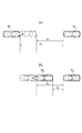
図4は、各走行区間と、各走行区間の境界線である判別直線とを示す図である。領域C1は、末尾区間を示す領域であって、判別直線B3と判別直線B1とで区切られている。領域C2は、中心区間を示す領域であって、判別直線B1と判別直線B2とで区切られている。領域C3は、回復区間を示す領域であって、判別直線B2と判別直線B3とで区切られている。 FIG. 4 is a diagram illustrating each traveling section and a discrimination line that is a boundary line between the traveling sections. The region C1 is a region indicating the end section, and is divided by the discrimination line B3 and the discrimination line B1. The region C2 is a region indicating a central section, and is divided by a discrimination line B1 and a discrimination line B2. A region C3 is a region indicating a recovery section, and is divided by a discrimination line B2 and a discrimination line B3.
例えば、第1番目及び第2番目の期間走行情報を判別関数(1)及び(2)により変換した座標は、領域C1に属している。第i番目及び第i+1番目の期間走行情報を判別関数(1)及び(2)により変換した座標は、領域C2に属している。第j番目及び第j+1番目の期間走行情報を判別関数(1)及び(2)により変換した座標は、領域C3に属している。このように、走行情報解析部22は、変数Z1及び変数Z2の座標空間において、期間走行情報に設定されている走行区間に応じて、期間走行情報が分類されるように、判別関数(1)及び(2)の係数及び定数を設定する。
For example, coordinates obtained by converting the first and second period travel information by the discriminant functions (1) and (2) belong to the region C1. The coordinates obtained by converting the i-th and (i + 1) -th period travel information by the discriminant functions (1) and (2) belong to the region C2. The coordinates obtained by converting the j-th and j + 1-th period travel information by the discriminant functions (1) and (2) belong to the region C3. As described above, the travel
走行区間判定部23は、走行情報取得部21により取得された現在の走行情報と走行情報解析部22による解析結果とに基づいて、車両が渋滞区間の少なくとも3つの区間のうちいずれの区間を走行中であるかを判定する走行区間判定手段として機能するものである。走行区間判定部23は、走行情報取得部21により取得された車速情報が示す車速が、渋滞開始閾値V1以下となった場合に、自車両が渋滞区間に入ったものと判定し、まず渋滞区間の末尾区間を走行しているものと判定する。
Based on the current travel information acquired by the travel
走行区間判定部23は、自車両が渋滞区間を走行していると判定すると、図5に示すように、走行情報取得部21により取得されている自車両の車速情報をT秒間の期間走行情報として、t0秒ごとに抽出する。そして、期間走行情報ごとに車速の平均、標準偏差、尖度、歪度、平均速度差を算出し、算出した各統計量と走行情報解析部22により算出された判別関数とに基づいて、変数Z1及び変数Z2の値を算出する。走行区間判定部23は、算出した変数Z1及び変数Z2の値により示される座標が、図4で示されるいずれの領域に属するか判定し、自車両が渋滞区間の末尾区間、中心区間、回復区間のいずれの区間を走行しているか判定する。
When the traveling
運転支援部24は、車両の運転支援を行う運転支援手段として機能するものである。運転支援部24は、走行区間判定部23によって判定された走行区間に応じて、自車両の運転支援を行う。運転支援の具体例については、後述する。なお、渋滞判定装置1は、ECU2が運転支援部24を備える場合、車両制御装置として機能する。
The driving support unit 24 functions as driving support means for driving the vehicle. The driving support unit 24 performs driving support for the host vehicle in accordance with the travel section determined by the travel
続いて、図6のフローチャートを用いて、本実施形態に係る渋滞判定装置1における走行区間判定処理の手順について説明する。
Next, the procedure of the travel section determination process in the traffic
走行区間判定部23は、走行情報取得部21によって取得された車速情報が示す車速が予め設定された渋滞開始閾値V1以下となったか否かを所定周期で判定する(S1)。ここで、渋滞開始閾値V1は、車両が渋滞区間に入ったと判断可能な速度であって、例えば40km/hである。自車両の車速が渋滞開始閾値V1より大きい場合(S1;No)、この判定処理が所定周期で繰り返される。一方で、自車両の車速が渋滞開始閾値V1以下の場合(S1;Yes)、走行区間判定部23は、自車両が渋滞区間に入ったものと判定し、自車両が渋滞区間の末尾区間を走行しているものと判定する(S2)。
The travel
次に、走行区間判定部23は、走行情報取得部21によって取得されている自車両の車速情報をT秒間の期間走行情報として、t0秒ごとに抽出する。そして、走行区間判定部23は、期間走行情報ごとに車速の平均、標準偏差、尖度、歪度及び平均速度差を算出し、走行情報解析部22により算出された判別関数に基づいて変数Z1及び変数Z2の値をそれぞれ算出する。そして、走行区間判定部23は、走行情報解析部22によって算出された末尾区間と中心区間との判別直線B1と、中心区間と回復区間との判別直線B2とに基づいて、当該期間走行情報が中心区間を示す領域C2に属するか否かの判定を行う(S3)。期間走行情報が中心区間を示す領域C2に属すると判定された場合(S3;Yes)、走行区間判定部23は、自車両が渋滞区間の中心区間を走行していると判定する(S4)。
Next, the travel
一方で、期間走行情報が中心区間を示す領域C2に属さないと判定された場合(S3;No)、走行区間判定部23は、走行情報解析部22によって算出された中心区間と回復区間との判別直線B2と、回復区間と末尾区間との判別直線B3とに基づいて、当該期間走行情報が回復区間を示す領域C3に属するか否かの判定を行う(S5)。期間走行情報が回復区間を示す領域C3に属すると判定された場合(S5;Yes)、走行区間判定部23は、自車両が渋滞区間の回復区間を走行していると判定する(S6)。一方で、期間走行情報が回復区間を示す領域C3に属さないと判定された場合(S5;No)、走行区間判定部23は、自車両が末尾区間を走行していると判定する(S7)。
On the other hand, when it is determined that the period travel information does not belong to the region C2 indicating the center section (S3; No), the travel
次に、走行区間判定部23は、走行情報取得部21によって取得された車速情報が示す車速が予め設定された渋滞終了閾値V2以下か否かを判定する(S8)。ここで、渋滞終了閾値V2は、車両が渋滞区間から抜け出たと判断可能な速度であって、例えば80km/hである。自車両の車速が渋滞終了閾値V2以下の場合(S8;Yes)、S3の処理に戻って、再度走行区間の判定処理を行う。一方で、自車両の車速が渋滞終了閾値V2より大きい場合(S8;No)、走行区間判定部23は、自車両が渋滞区間から抜け自由走行しているものと判定して(S9)、走行区間判定処理を終了する。
Next, the travel
なお、期間走行情報が中心区間を示す領域C2に属するか否かの判定(S3)と期間走行情報が回復区間を示す領域C3に属するか否かの判定(S5)との処理に代えて、期間走行情報が末尾区間を示す領域C1、中心区間を示す領域C2、回復区間を示す領域C3のいずれの領域に属するかの判定を行うようにしてもよい。 In place of the process of determining whether or not the period travel information belongs to the area C2 indicating the central section (S3) and determining whether or not the period travel information belongs to the area C3 indicating the recovery section (S5), It may be determined whether the period travel information belongs to an area C1 indicating the end section, an area C2 indicating the center section, or an area C3 indicating the recovery section.
続いて、本実施形態に係る渋滞判定装置1における運転支援の具体例について以下に説明を行う。
Subsequently, a specific example of driving assistance in the traffic
図7は、渋滞判定装置1における運転支援の一例を示す図である。運転支援部24は、走行区間判定部23によって判定された自車両が走行している区間に応じて、推奨速度を設定する。渋滞区間の末尾区間では、車速は低周波で変動し、変動幅が大きい傾向にある。このため、運転支援部24は、自車両が末尾区間を走行していると判定された場合、走行情報記憶部9に記憶されている過去の走行情報に基づいて末尾区間における平均速度を算出し、算出した平均速度を末尾区間における推奨速度に設定する。
FIG. 7 is a diagram illustrating an example of driving assistance in the
また、渋滞区間の中心区間では、車速は安定した変動を示す傾向にある。このため、運転支援部24は、自車両が中心区間を走行していると判定された場合、走行情報取得部21によって取得された車速情報が示す車速に基づいて長期間(例えば、200秒)での平均速度を算出する。そして、運転支援部24は、算出した平均速度を中心区間における推奨速度に設定する。また、渋滞区間の回復期間では、車速は上昇を基調とした変動を示す傾向にある。このため、運転支援部24は、自車両が回復区間を走行していると判定された場合、走行情報取得部21によって取得された車速情報が示す車速に基づいて短期間(例えば、50秒)での平均速度を算出する。
Further, in the central section of the traffic jam section, the vehicle speed tends to show a stable fluctuation. For this reason, when it determines with the own vehicle driving | running | working the center area, the driving assistance part 24 is long-term (for example, 200 second) based on the vehicle speed which the vehicle speed information acquired by the driving
そして、運転支援部24は、算出した平均速度を回復区間における推奨速度に設定する。図7の曲線Vrは、このようにして設定した推奨速度を示す。運転支援部24は、例えば設定した推奨速度を中心速度として、加減速制御を行うよう、エンジンECU11及びブレーキECU12に加減速度情報を送信する。また、運転支援部24は、設定した推奨速度を表示装置7に表示し、自車両の車速が推奨速度を超える場合に警告を表示する等してもよい。このように、自車両が走行している区間に応じて推奨速度を設定することで、自車両が無駄な加速を行わないように誘導することができる。このため、自車両の燃費を向上でき、効率的な走行を行うことができる。
Then, the driving support unit 24 sets the calculated average speed as the recommended speed in the recovery section. A curve Vr in FIG. 7 shows the recommended speed set in this way. For example, the driving support unit 24 transmits acceleration / deceleration information to the
運転支援部24は、先行車両との車間制御をバネマス系運動として、車間制御ECU13に制御を行うように指示してもよい。具体的に説明すると、運転支援部24は、走行情報解析部22によって算出された車速の標準偏差に応じて、ばね定数k、減衰係数Cを変更する。運転支援部24は、ばね定数k、減衰係数Cを含む車間制御情報を車間制御ECU13に送信する。このようにすることで、渋滞状態を加味した車間制御が可能となる。
The driving support unit 24 may instruct the inter-vehicle
運転支援部24は、走行区間判定部23によって判定された自車両が走行している区間に応じて、車間制御ECU13に車間距離の制御を行うように指示してもよい。図8(a)は、末尾区間における自車両Maと先行車両Mbとの車間の一例を示す図である。図8(a)に示すように、車間d0は、自車両Maが通常走行している場合の先行車両Mbとの目標車間である。車間d1は、自車両Maが渋滞区間の末尾区間を走行している場合の先行車両Mbとの目標車間である。自車両Maが渋滞区間の末尾区間を走行していると判定された場合、自車両Maは減速すると考えられる。したがって、通常走行時の車間d0よりも大きい車間d1を許容する。運転支援部24は、この車間d1を含む車間制御情報を車間制御ECU13に送信する。
The driving support unit 24 may instruct the
図8(b)は、回復区間における自車両Maと先行車両Mbとの車間の一例を示す図である。図8(b)に示すように、車間d0は、自車両Maが通常走行している場合の先行車両Mbとの目標車間である。車間d2は、自車両Maが渋滞区間の回復区間を走行している場合の先行車両Mbとの目標車間である。自車両Maが渋滞区間の回復区間を走行していると判定された場合、自車両Maは速度回復(加速)すると考えられる。したがって、通常走行時の車間d0よりも小さい車間d2を許容する。運転支援部24は、この車間d2を含む車間制御情報を車間制御ECU13に送信する。
8 (b) is a diagram showing an example of a vehicle of the own vehicle M a and the preceding vehicle M b in the recovery section. As shown in FIG. 8 (b), the inter-vehicle d 0 is the target vehicle between the preceding vehicle M b of when the vehicle M a is normal running. Vehicle d 2 is the target vehicle between the preceding vehicle M b of when the vehicle M a is traveling recovery section of the congestion area. When the vehicle M a is determined to be traveling in the recovery period of the congestion area, the vehicle M a is considered Then speed recovery (acceleration). Accordingly, the inter-vehicle distance d 2 that is smaller than the inter-vehicle distance d 0 during normal travel is allowed. The driving support unit 24 transmits the inter-vehicle distance control information including the inter-vehicle distance d 2 to the inter-vehicle
自車両Maが中心区間を走行している場合、運転支援部24は、走行情報取得部21によって取得された車速情報が示す車速に基づいて平均速度を算出する。そして、運転支援部24は、算出した平均速度に所定の加算値を加えた速度を上限速度として加減速制御を行うよう、エンジンECU11及びブレーキECU12に加減速度情報を送信するようにしてもよい。
When the vehicle M a is running on a central section, the driving support unit 24 calculates an average speed based on the vehicle speed indicating the vehicle speed information acquired by the traveling
このように、本実施形態の渋滞判定装置によれば、複数の走行情報を解析し、現在の走行情報と解析結果とに基づいて、車両が渋滞区間の末尾区間、中心区間、回復区間のうちいずれの区間を走行中であるかを判定することによって、車両が渋滞区間のどの区間を現在走行しているか認識できる。このため、例えば、渋滞区間の走行区間に応じて適切な運転支援を行う等、渋滞区間の走行区間に応じた制御を行うことが可能となる。その結果、車両の燃費向上を実現することが可能となる。 As described above, according to the traffic jam determination device of the present embodiment, a plurality of travel information is analyzed, and based on the current travel information and the analysis result, the vehicle is selected from the end zone, the central zone, and the recovery zone of the traffic jam zone. By determining which section is traveling, it is possible to recognize which section of the congestion section the vehicle is currently traveling. For this reason, for example, it becomes possible to perform control according to the travel section of the traffic jam section, such as performing appropriate driving support according to the travel section of the traffic jam section. As a result, it is possible to improve the fuel efficiency of the vehicle.
なお、本発明に係る渋滞判定装置、及び車両制御装置は上記実施形態に記載したものに限定されるものではない。 In addition, the traffic congestion determination apparatus and vehicle control apparatus which concern on this invention are not limited to what was described in the said embodiment.
例えば、上記実施形態では、走行情報取得部21は、車速センサ4から車速情報を受信しているが、通信装置8を介して他車両や情報センター(サーバ)等から渋滞領域情報により示される領域に関する車速情報等の走行情報を取得してもよい。このようにすることで、より多くの走行情報に基づいて解析を行うことができ、解析の精度を高めることができる。その結果、走行区間の判定精度を高めることが可能となる。また、他車両又は情報センター(サーバ)等から走行情報を取得する場合、走行区間判定部23は、各他車両が渋滞区間の少なくとも3つの区間のうちいずれの区間を走行中であるかを判定するようにしてもよい。
For example, in the above embodiment, the travel
上記実施形態では、渋滞区間を末尾区間、中心区間、回復区間の3つの走行区間に分類しているが、これに限定されるものではなく、車両の走行状態に基づいてさらに複数の走行区間に分類してもよい。また、走行情報解析部22は、車速情報に基づいて渋滞区間を複数の走行区間に分類しているが、加速度情報等の走行情報に基づいて渋滞区間を複数の走行区間に分類してもよい。また、走行情報解析部22は、複数の走行情報に基づいて渋滞区間を複数の走行区間に分類してもよい。また、走行情報解析部22は、多変量解析により渋滞区間を複数の走行区間に分類しているが、他の解析方法を用いて渋滞区間を複数の走行区間に分類してもよい。
In the above embodiment, the traffic jam section is classified into three travel sections, the tail section, the central section, and the recovery section. However, the present invention is not limited to this, and the traffic section is further divided into a plurality of travel sections based on the vehicle travel state. You may classify. In addition, the travel
上記実施形態では、N回分の走行情報に対して、運転者が渋滞区間の末尾区間、中心区間、回復区間を設定しているが、走行情報解析部22が、走行状態の変化に応じて末尾区間、中心区間、回復区間を設定するようにしてもよい。
In the above embodiment, the driver sets the tail section, the central section, and the recovery section of the traffic jam section for the N times of travel information, but the travel
走行情報解析部22は、渋滞領域情報により示される領域ごとに判別関数を求め、渋滞領域情報により示される領域ごとに判別直線を求めるのが好ましい。また、走行情報解析部22は、時間帯ごとに判別関数を求め、時間帯ごとに判別直線を求めてもよい。このようにすることで、走行区間の判定精度をより一層高めることが可能となる。
The travel
走行区間判定部23は、走行情報解析部22の解析結果に代えて、他車両における解析結果(例えば、判別関数及び判別直線)、又は、不図示の情報センターにおける解析結果(例えば、判別関数及び判別直線)に基づいて、車両が渋滞区間の少なくとも3つの区間のうちいずれの区間を走行中であるかを判定するようにしてもよい。また、判別関数及び判別直線を予め設定しておいてもよい。かかる場合には、渋滞判定装置1は、走行情報解析部22を備える必要はない。
The travel
さらに、渋滞判定装置1は、他車両の走行状態に関する走行情報を取得する他車両情報取得部(他車両情報取得手段)と、他車両が渋滞区間を走行しているか否かを判定する他車両走行区間判定部(他車両走行区間判定手段)と、をさらに備えてもよい。他車両情報取得部は、不図示の車載カメラから受信した画像情報、不図示のレーダから受信した他車両までの距離情報等に基づいて、他車両の位置、速度、加速度等の他車両の走行情報を算出する。あるいは、他車両情報取得部は、通信装置8を介して他車両の走行情報を取得する。
Furthermore, the
そして、他車両走行区間判定部は、走行区間判定部23と同様にして、他車両の車速が渋滞開始閾値V1以下となったか否かを判定することにより、他車両が渋滞区間を走行しているか否かを判定する。また、他車両走行区間判定部は、渋滞終了閾値V2以下か否かを判定することにより、他車両が渋滞区間から抜け出したか否かを判定する。
Then, in the same manner as the travel
運転支援部24は、他車両走行区間判定部の判定結果に基づいて、運転支援を行ってもよい。具体的に説明すると、他車両走行区間判定部によって他車両が渋滞区間を走行していると判定した場合、例えば、減速支援を行うか否かの判定に用いられる自車両と他車両との車間距離の閾値を、他車両が通常走行している場合よりも小さくする。このように、他車両が渋滞区間を走行しているか否かに応じて、自車両の運転支援を変更することで、より適切な運転支援を行うことが可能となる。 The driving support unit 24 may perform driving support based on the determination result of the other vehicle travel section determination unit. Specifically, when the other vehicle travel section determination unit determines that the other vehicle is traveling in the traffic jam section, for example, the distance between the host vehicle and the other vehicle used for determining whether or not to perform deceleration support The threshold of the distance is made smaller than when the other vehicle is traveling normally. As described above, it is possible to perform more appropriate driving support by changing the driving support of the own vehicle according to whether or not the other vehicle is traveling in the traffic jam section.
また、上記実施形態では、渋滞判定装置1は自車両に搭載されているが、これに限定されない。例えば不図示の情報センターが、渋滞判定装置1を備えるようにしてもよい。この場合、情報センターは、各車両から走行情報を取得し、複数の走行情報の解析を行って、例えば、判別関数及び判別直線を算出するようにしてもよい。そして、情報センターは、判別関数及び判別直線に基づいて、各車両の現在の走行情報から、各車両が渋滞区間の末尾区間、中心区間、回復区間のうちいずれの区間を走行中であるかを判定するようにしてもよい。このように、情報センターは、複数の車両の走行情報の解析を行って、判別関数及び判別直線を算出することができる。このため、より精度の高い解析を行うことが可能となる。また、各車両が渋滞判定装置1を備えていなくても、各車両の渋滞区間における走行区間を判定することが可能となる。
Moreover, in the said embodiment, although the traffic
1…渋滞判定装置(車両制御装置)、2…ECU、3…ナビゲーションシステム、4…車速センサ、5…加速度センサ、6…入力装置、7…表示装置、8…通信装置、9…走行情報記憶部、10…車載ECU、21…走行情報取得部(走行情報取得手段)、22…走行情報解析部(走行情報解析手段)、23…走行区間判定部(走行区間判定手段)、24…運転支援部(運転支援手段)
DESCRIPTION OF
Claims (8)
前記走行情報取得手段により取得された前記複数の車両の走行情報を解析し、車両が減速傾向を示す末尾区間、車両が安定した速度変動を示す中心区間、及び、車両が加速傾向を示す回復区間を含む少なくとも3つの区間に、渋滞区間を分類する走行情報解析手段と、
前記走行情報取得手段により取得された前記複数の車両の現在の走行情報に基づいて、前記複数の車両の各々が前記少なくとも3つの区間のいずれの区間を走行中であるかを判定する走行区間判定手段と、
を備え、
前記走行情報解析手段は、車両の速度に関する多変量解析を行うことで、渋滞区間を前記少なくとも3つの区間に分類する、
渋滞判定装置。 Travel information acquisition means for acquiring travel information relating to the travel states of a plurality of vehicles;
The travel information of the plurality of vehicles acquired by the travel information acquisition means is analyzed, the end section in which the vehicle exhibits a deceleration tendency, the central section in which the vehicle exhibits stable speed fluctuations, and the recovery section in which the vehicle exhibits an acceleration tendency A travel information analysis means for classifying a traffic jam section into at least three sections including
Based on the current travel information of the plurality of vehicle acquired by the traveling information acquisition unit, traveling zone determination determines whether each of the plurality of vehicles are traveling one section of the at least three sections Means,
Equipped with a,
The travel information analysis means classifies a traffic jam section into the at least three sections by performing multivariate analysis on the speed of the vehicle.
Traffic jam judging device.
前記走行区間判定手段の判定結果に基づいて前記車両の運転支援を行う運転支援手段と、
を備える車両制御装置。 A traffic jam judging device according to claim 1 ;
Driving support means for supporting driving of the vehicle based on the determination result of the traveling section determination means;
A vehicle control device comprising:
前記他車両情報取得手段により取得された前記他車両の走行情報と、前記走行情報解析手段による解析結果と、に基づいて、前記他車両が渋滞区間を走行中であるか否かを判定する他車両走行区間判定手段と、
をさらに備え、
前記運転支援手段は、前記他車両走行区間判定手段の判定結果に基づいて、前記車両の運転支援を行う、
請求項2に記載の車両制御装置。 Other vehicle information acquisition means for acquiring travel information related to the travel state of other vehicles;
And traveling information of the other vehicle acquired by the other vehicle information acquisition unit, an analysis result by the traveling information analysis unit, based on the other determines whether the other vehicle is traveling on a congested section Vehicle travel section determination means;
Further comprising
The driving support means performs driving support of the vehicle based on a determination result of the other vehicle travel section determination means.
The vehicle control device according to claim 2 .
請求項2または請求項3に記載の車両制御装置。The vehicle control device according to claim 2 or claim 3.
前記入力手段を介して、前記複数の走行情報に対して前記少なくとも3つの区間の設定が行われる、 The at least three sections are set for the plurality of travel information via the input means.
請求項2〜請求項4のいずれか一項に記載の車両制御装置。The vehicle control device according to any one of claims 2 to 4.
請求項2〜請求項5のいずれか一項に記載の車両制御装置。The vehicle control device according to any one of claims 2 to 5.
請求項2〜請求項6のいずれか一項に記載の車両制御装置。The vehicle control device according to any one of claims 2 to 6.
請求項2〜請求項7のいずれか一項に記載の車両制御装置。The vehicle control device according to any one of claims 2 to 7.
Priority Applications (5)
| Application Number | Priority Date | Filing Date | Title |
|---|---|---|---|
| JP2011022019A JP5263312B2 (en) | 2011-02-03 | 2011-02-03 | Traffic jam judging device and vehicle control device |
| CN201280007202.8A CN103348395B (en) | 2011-02-03 | 2012-02-03 | Traffic congestion detection apparatus and vehicle control apparatus |
| DE112012000680T DE112012000680T5 (en) | 2011-02-03 | 2012-02-03 | Traffic jam detection device and vehicle control device |
| PCT/IB2012/000181 WO2012104720A1 (en) | 2011-02-03 | 2012-02-03 | Traffic congestion detection apparatus and vehicle control apparatus |
| US13/983,478 US9159227B2 (en) | 2011-02-03 | 2012-02-03 | Traffic congestion detection apparatus and vehicle control apparatus |
Applications Claiming Priority (1)
| Application Number | Priority Date | Filing Date | Title |
|---|---|---|---|
| JP2011022019A JP5263312B2 (en) | 2011-02-03 | 2011-02-03 | Traffic jam judging device and vehicle control device |
Publications (2)
| Publication Number | Publication Date |
|---|---|
| JP2012164025A JP2012164025A (en) | 2012-08-30 |
| JP5263312B2 true JP5263312B2 (en) | 2013-08-14 |
Family
ID=45815911
Family Applications (1)
| Application Number | Title | Priority Date | Filing Date |
|---|---|---|---|
| JP2011022019A Active JP5263312B2 (en) | 2011-02-03 | 2011-02-03 | Traffic jam judging device and vehicle control device |
Country Status (5)
| Country | Link |
|---|---|
| US (1) | US9159227B2 (en) |
| JP (1) | JP5263312B2 (en) |
| CN (1) | CN103348395B (en) |
| DE (1) | DE112012000680T5 (en) |
| WO (1) | WO2012104720A1 (en) |
Families Citing this family (26)
| Publication number | Priority date | Publication date | Assignee | Title |
|---|---|---|---|---|
| ES2536328T3 (en) * | 2012-09-28 | 2015-05-22 | Telenav Gmbh | Procedure for the determination of particular traffic situations in road traffic |
| US9197705B2 (en) * | 2013-04-12 | 2015-11-24 | Samsung Electronics Co., Ltd. | Method and apparatus for supporting driving using wireless communication network and system thereof |
| ITTO20130304A1 (en) * | 2013-04-15 | 2013-07-15 | Stefania Viano | METHOD FOR ADJUSTING AND OPTIMIZING THE ROAD FLOW OF VEHICLES |
| US9557179B2 (en) * | 2013-08-20 | 2017-01-31 | Qualcomm Incorporated | Navigation using dynamic speed limits |
| JP6263402B2 (en) * | 2013-10-11 | 2018-01-17 | 株式会社デンソーアイティーラボラトリ | Safe speed information generation device, safe speed generation method, and program |
| CN103903465B (en) * | 2014-04-17 | 2016-04-27 | 北京易华录信息技术股份有限公司 | A kind of congestion in road reason real-time release method and system |
| CN103927901B (en) * | 2014-04-21 | 2016-08-17 | 北京易华录信息技术股份有限公司 | A kind of accurate recording viewing area congestion in road causes the method and system of point |
| CN103927868B (en) * | 2014-04-24 | 2016-03-09 | 北京易华录信息技术股份有限公司 | A kind ofly can find the method and system causing area traffic jamming reason |
| CN105303862A (en) * | 2014-06-11 | 2016-02-03 | 陕西重型汽车有限公司 | Vehicle intelligent control system |
| CN105023445A (en) * | 2014-07-04 | 2015-11-04 | 吴建平 | Regional traffic dynamic regulation-control method and system |
| CN105792137B (en) * | 2014-12-26 | 2019-01-01 | 中国移动通信集团公司 | A kind of method and device of inter-vehicular communication |
| CN104537890B (en) * | 2015-01-04 | 2017-06-20 | 天台远大交通设施有限公司 | Road early warning system, method for early warning and its distant early warning device |
| CN104574968B (en) * | 2015-01-19 | 2017-02-01 | 浙江大学 | Determining method for threshold traffic state parameter |
| KR102623680B1 (en) * | 2015-02-10 | 2024-01-12 | 모빌아이 비젼 테크놀로지스 엘티디. | Sparse map for autonomous vehicle navigation |
| NO3073450T3 (en) * | 2015-03-27 | 2018-02-24 | ||
| US9821812B2 (en) * | 2015-04-23 | 2017-11-21 | Ford Global Technologies, Llc | Traffic complexity estimation |
| KR101741433B1 (en) * | 2015-06-09 | 2017-05-30 | 엘지전자 주식회사 | Driver assistance apparatus and control method for the same |
| KR20180051273A (en) * | 2016-11-08 | 2018-05-16 | 현대자동차주식회사 | Method for controlling driving of vehicle using driving information of vehicle and vehicle using the same |
| CN107248282B (en) * | 2017-06-29 | 2021-07-02 | 浩鲸云计算科技股份有限公司 | Method for acquiring road running state grade |
| US10593201B2 (en) * | 2017-09-26 | 2020-03-17 | Telenav, Inc. | Computer system with traffic control mechanism and method of operation thereof |
| GB2569156B (en) * | 2017-12-07 | 2020-08-26 | Maritech Development Ltd | A method of determining an optimal route |
| CN110021161B (en) * | 2018-01-09 | 2021-12-21 | 株式会社日立制作所 | Traffic flow direction prediction method and system |
| CN111670466B (en) * | 2018-02-09 | 2022-06-24 | 三菱电机株式会社 | Communication device and computer-readable recording medium |
| JP2020143899A (en) * | 2019-03-04 | 2020-09-10 | 本田技研工業株式会社 | Vehicle control device, vehicle and vehicle control method |
| CN113947897B (en) * | 2021-09-26 | 2023-04-07 | 北京百度网讯科技有限公司 | Method, device and equipment for acquiring road traffic condition and automatic driving vehicle |
| CN114023069B (en) * | 2021-11-18 | 2022-07-29 | 北京图盟科技有限公司 | Abnormal parking detection method, device and equipment and readable storage medium |
Family Cites Families (28)
| Publication number | Priority date | Publication date | Assignee | Title |
|---|---|---|---|---|
| JP3993316B2 (en) * | 1998-08-19 | 2007-10-17 | 本田技研工業株式会社 | Vehicle travel safety device |
| JP3534622B2 (en) * | 1998-08-21 | 2004-06-07 | 日本電信電話株式会社 | Travel time calculation method and apparatus, and recording medium recording travel time calculation program |
| CA2266208C (en) * | 1999-03-19 | 2008-07-08 | Wenking Corp. | Remote road traffic data exchange and intelligent vehicle highway system |
| JP3690185B2 (en) * | 1999-05-25 | 2005-08-31 | 日産自動車株式会社 | Preceding vehicle tracking control device |
| DE10036789A1 (en) * | 2000-07-28 | 2002-02-07 | Daimler Chrysler Ag | Method for determining the traffic condition in a traffic network with effective bottlenecks |
| JP4201155B2 (en) * | 2000-11-22 | 2008-12-24 | 道弘 観音寺 | Inter-vehicle distance alarm device |
| JP3806024B2 (en) * | 2001-11-21 | 2006-08-09 | 東日本電信電話株式会社 | Vehicle travel time calculation system, travel time calculation method, travel time calculation system program, and travel time calculation system recording medium |
| JP4123949B2 (en) * | 2003-01-30 | 2008-07-23 | マツダ株式会社 | Vehicle navigation system, computer program for vehicle navigation, and vehicle navigation apparatus |
| JP4200863B2 (en) * | 2003-09-16 | 2008-12-24 | 株式会社エクォス・リサーチ | Traveling speed pattern estimation device and hybrid vehicle drive control device |
| JP2005165388A (en) | 2003-11-28 | 2005-06-23 | Fujitsu Ltd | Traveling information communication method in road traffic information management system and on-vehicle navigation device |
| US20050137783A1 (en) * | 2003-12-17 | 2005-06-23 | Dort David B. | Traffic control and vehicle spacer system for the prevention of highway gridlock |
| US7092815B2 (en) * | 2003-12-17 | 2006-08-15 | Vrbia, Inc. | Traffic control systems for vehicle spacing to dissipate traffic gridlock |
| JP4412018B2 (en) * | 2004-03-19 | 2010-02-10 | アイシン・エィ・ダブリュ株式会社 | Navigation system |
| JP4428134B2 (en) | 2004-05-13 | 2010-03-10 | アイシン・エィ・ダブリュ株式会社 | Vehicle control device |
| JP4175312B2 (en) * | 2004-09-17 | 2008-11-05 | 株式会社日立製作所 | Traffic information prediction device |
| JP2006138742A (en) * | 2004-11-12 | 2006-06-01 | Aisin Aw Co Ltd | Information acquisition system, and program of information acquisition method |
| JP4591395B2 (en) * | 2006-03-31 | 2010-12-01 | アイシン・エィ・ダブリュ株式会社 | Navigation system |
| JP2008006993A (en) * | 2006-06-29 | 2008-01-17 | Toyota Motor Corp | Vehicle control device |
| JP4982143B2 (en) * | 2006-09-27 | 2012-07-25 | クラリオン株式会社 | Traffic situation prediction device |
| JP2008281448A (en) | 2007-05-10 | 2008-11-20 | Toyota Motor Corp | Driving support device for vehicle |
| JP4938591B2 (en) * | 2007-08-22 | 2012-05-23 | トヨタ自動車株式会社 | Traffic information creation method, traffic information creation device and navigation system |
| JP4893598B2 (en) | 2007-11-19 | 2012-03-07 | アイシン・エィ・ダブリュ株式会社 | Driving support system, driving support method, and computer program |
| JP5024879B2 (en) * | 2007-11-30 | 2012-09-12 | トヨタ自動車株式会社 | Traffic information creation method and traffic information creation device |
| JP2010102575A (en) * | 2008-10-24 | 2010-05-06 | Panasonic Corp | Apparatus and method for generating traffic information |
| US8352111B2 (en) * | 2009-04-06 | 2013-01-08 | GM Global Technology Operations LLC | Platoon vehicle management |
| US9457810B2 (en) * | 2009-10-21 | 2016-10-04 | Berthold K. P. Horn | Method and apparatus for reducing motor vehicle traffic flow instabilities and increasing vehicle throughput |
| CN101719314B (en) * | 2009-11-17 | 2011-08-10 | 姜廷顺 | Area traffic jamming triggering point record analysis system and operation method thereof |
| JP2012153296A (en) * | 2011-01-27 | 2012-08-16 | Toyota Motor Corp | Running control apparatus |
-
2011
- 2011-02-03 JP JP2011022019A patent/JP5263312B2/en active Active
-
2012
- 2012-02-03 CN CN201280007202.8A patent/CN103348395B/en not_active Expired - Fee Related
- 2012-02-03 WO PCT/IB2012/000181 patent/WO2012104720A1/en active Application Filing
- 2012-02-03 US US13/983,478 patent/US9159227B2/en not_active Expired - Fee Related
- 2012-02-03 DE DE112012000680T patent/DE112012000680T5/en not_active Withdrawn
Also Published As
| Publication number | Publication date |
|---|---|
| DE112012000680T5 (en) | 2013-11-14 |
| US9159227B2 (en) | 2015-10-13 |
| JP2012164025A (en) | 2012-08-30 |
| WO2012104720A1 (en) | 2012-08-09 |
| US20130325284A1 (en) | 2013-12-05 |
| CN103348395A (en) | 2013-10-09 |
| CN103348395B (en) | 2015-06-17 |
Similar Documents
| Publication | Publication Date | Title |
|---|---|---|
| JP5263312B2 (en) | Traffic jam judging device and vehicle control device | |
| US11312378B2 (en) | System and method for vehicle control using vehicular communication | |
| US11338813B2 (en) | System and method for merge assist using vehicular communication | |
| US11275382B2 (en) | Autonomous driving system | |
| US11023751B2 (en) | Systems and methods for safe route determination | |
| JP5900454B2 (en) | Vehicle lane guidance system and vehicle lane guidance method | |
| US10343686B2 (en) | Autonomous driving system | |
| JP6852793B2 (en) | Lane information management method, driving control method and lane information management device | |
| US9666066B2 (en) | Unexpectedness prediction sensitivity determination apparatus | |
| JP5907249B2 (en) | Unexpected prediction sensitivity judgment device | |
| JP2016018495A (en) | Travel support device and travel support method | |
| CN110740916A (en) | Processing request signals related to operation of autonomous vehicles | |
| KR102539286B1 (en) | Autonomous driving apparatus and method | |
| JP2012153296A (en) | Running control apparatus | |
| US11580789B2 (en) | System load based safety operator warning system | |
| JP6096750B2 (en) | Driving support device | |
| JP5889085B2 (en) | Driving assistance device | |
| JP2022139437A (en) | Vehicle driving assistance system and information processing device | |
| JP2007127489A (en) | Navigation device, navigation method, navigation system and program |
Legal Events
| Date | Code | Title | Description |
|---|---|---|---|
| A977 | Report on retrieval |
Free format text: JAPANESE INTERMEDIATE CODE: A971007 Effective date: 20121121 |
|
| A131 | Notification of reasons for refusal |
Free format text: JAPANESE INTERMEDIATE CODE: A131 Effective date: 20121127 |
|
| A521 | Request for written amendment filed |
Free format text: JAPANESE INTERMEDIATE CODE: A523 Effective date: 20130125 |
|
| TRDD | Decision of grant or rejection written | ||
| A01 | Written decision to grant a patent or to grant a registration (utility model) |
Free format text: JAPANESE INTERMEDIATE CODE: A01 Effective date: 20130402 |
|
| A61 | First payment of annual fees (during grant procedure) |
Free format text: JAPANESE INTERMEDIATE CODE: A61 Effective date: 20130415 |
|
| R151 | Written notification of patent or utility model registration |
Ref document number: 5263312 Country of ref document: JP Free format text: JAPANESE INTERMEDIATE CODE: R151 |