JP4201155B2 - Inter-vehicle distance alarm device - Google Patents
Inter-vehicle distance alarm device Download PDFInfo
- Publication number
- JP4201155B2 JP4201155B2 JP2000399361A JP2000399361A JP4201155B2 JP 4201155 B2 JP4201155 B2 JP 4201155B2 JP 2000399361 A JP2000399361 A JP 2000399361A JP 2000399361 A JP2000399361 A JP 2000399361A JP 4201155 B2 JP4201155 B2 JP 4201155B2
- Authority
- JP
- Japan
- Prior art keywords
- inter
- vehicle
- distance
- output signal
- vehicle distance
- Prior art date
- Legal status (The legal status is an assumption and is not a legal conclusion. Google has not performed a legal analysis and makes no representation as to the accuracy of the status listed.)
- Expired - Fee Related
Links
- 238000001514 detection method Methods 0.000 claims description 31
- 238000005259 measurement Methods 0.000 claims description 15
- 238000013459 approach Methods 0.000 description 58
- 239000004973 liquid crystal related substance Substances 0.000 description 24
- 230000008859 change Effects 0.000 description 23
- 238000000034 method Methods 0.000 description 13
- 230000008569 process Effects 0.000 description 9
- 238000010586 diagram Methods 0.000 description 5
- 230000007423 decrease Effects 0.000 description 3
- 230000003247 decreasing effect Effects 0.000 description 3
- 230000006870 function Effects 0.000 description 3
- 230000002265 prevention Effects 0.000 description 3
- 238000012545 processing Methods 0.000 description 3
- 230000000694 effects Effects 0.000 description 2
- 238000005516 engineering process Methods 0.000 description 2
- 239000007787 solid Substances 0.000 description 2
- 206010039203 Road traffic accident Diseases 0.000 description 1
- 238000012790 confirmation Methods 0.000 description 1
- 230000003111 delayed effect Effects 0.000 description 1
- 230000000994 depressogenic effect Effects 0.000 description 1
- 230000006872 improvement Effects 0.000 description 1
- 230000004044 response Effects 0.000 description 1
Images


Classifications
-
- G—PHYSICS
- G08—SIGNALLING
- G08G—TRAFFIC CONTROL SYSTEMS
- G08G1/00—Traffic control systems for road vehicles
- G08G1/16—Anti-collision systems
- G08G1/161—Decentralised systems, e.g. inter-vehicle communication
Description
【0001】
【発明の属する技術分野】
この発明は、自車両の速度制御装置に連動するセンサからの信号や、自車両から前方走行車までの車間距離の測定に基づいて自車両が前方走行車に追突などの衝突を防止するための車間距離警報装置に関するものである。
【0002】
【従来の技術】
従来より、自車両に搭載した車間距離測定器を用いて前方走行車との追突事故を防止する装置が種々考案されている。本願出願人においても、特公平4−31074号や特公平4−79551号にて衝突予知装置を、また、特願平9−41307号や発明協会公開技報98−6409号にて新しい追突警報装置ならびにその車間距離表示方法について、さらには特開平4−340200号や公開技報98−6876号では、車間距離の変化を報知するための車間距離報知装置を提案している。
【0003】
ところで、複数の車両が安全に走行している状態では、自車両と前方走行車との車間距離が接近すれば、自車両のドライバはアクセルペダルを戻したり、ブレーキペダルを踏んで自車両の速度を減速させ、前方走行車との車間距離の変化に対応した処置を行うことで衝突(追突)事故などを防いでいる。このことから、衝突(追突)事故の原因の一つとして、上記一連の操作がなされなかったり、あるいはその操作遅れによるものと言える。
【0004】
【発明が解決しようとする課題】
ところが従来の技術では、わき見運転等により上記一連の操作がなされなかったり、あるいはその操作遅れがあった時にそれを正しく検出して追突事故等を未然に防ぐことのできる信頼性のある装置が、広く実用化するまでには至っていなかった。
そこで本発明の目的は、自車両が前方走行車に接近した時に、アクセルペダルの操作によって信号を発生するセンサからの出力信号値の変化をもとにして、車間距離の接近に対するドライバの反応を調べ、衝突の可能性がある場合警報を発して事故を未然に防ぐ、新しい車間距離警報装置を提供するものである。
また、本発明の他の目的は、従来から提案されている警報装置の改良に関し、刻々と変化する車間距離に的確に対応する車間距離警報装置を提案するものである。さらにこれらの装置に最適な表示装置により、その操作状況が一目瞭然となり、安全走行のための指標としてより実用性、信頼性を高めた車間距離警報装置とすることにある。
【0005】
【課題を解決するための手段】
この発明の第1の局面に係る車間距離警報装置は、自車両に搭載した車間距離測定器と、自車両のアクセルペダルの操作によって出力信号が変化するセンサと、前記センサからの出力信号値が所定時間一定になったことにより、前記センサの出力信号値をもとに出力信号値の基準範囲を記憶する記憶手段と、前記車間距離測定器によって、前記センサからの出力信号値が所定時間一定になった時の車間距離に対応して予め設定された車間距離を測定したことに応答して、さらに前記センサからの出力信号値が前記記憶手段に記憶された出力信号値の基準範囲内か否かに基づいて衝突の可能性を判定し、警報を出力するための手段とを備えたことを特徴とするものである。
【0006】
この発明の第2の局面に係る車間距離警報装置は、自車両に搭載した車間距離測定器により前方走行車までの車間距離を測定し、予め設定された車間距離の検出に基づいて衝突の危険を報知するための警報器を作動させるようにした車間距離警報装置であって、前記車間距離測定器により測定された、前方走行車と自車両との車間距離が所定時間一定になってから、前記警報器の作動する距離を表示する表示器を含む。
【0007】
この発明の第3の局面に係る車間距離警報装置は、自車両に搭載した車間距離測定器により前方走行車までの車間距離を測定し、予め設定された車間距離の検出に基づいて衝突の危険を報知するための警報器を作動させるようにした車間距離警報装置であって、前記車間距離測定器により測定された、前方走行車と自車両との車間距離が所定時間一定になってから、前記車間距離測定器で測定される前方走行車までの距離と前記警報器の作動する距離との差を表示する表示器を含む。
【0008】
上記第2又は第3の局面に係る車間距離警報装置における一の態様では、前記警報器が作動する距離は、車間距離が所定時間一定になった時の車間距離に対応して予め設定されている距離である。
【0009】
また、上記第2又は第3の局面に係る車間距離警報装置における他の態様では、前記警報器が作動する距離は、車間距離が所定時間一定になった時の自車両の速度に応じて予め設定されている距離である。
【0010】
さらに、上記第2又は第3の局面に係る車間距離警報装置は、自車両のアクセルペダルの操作によって出力信号が変化するセンサと、車間距離が所定時間一定になった時の、前記センサからの出力信号値をもとにして設定された出力信号値の基準範囲を記憶する記憶手段と、前記センサからの出力信号値が前記記憶手段に記憶されている出力信号値の基準範囲外となった場合には、前記表示器上の表示を消去するための手段とをさらに含む。
【0011】
この発明の第4の局面に係る車間距離警報装置は、自車両に搭載した車間距離測定器により前方走行車までの車間距離を測定し、予め設定された車間距離の検出に基づいて衝突の危険を報知するための警報器を作動させるようにした車間距離警報装置であって、自車両のアクセルペダルの操作によって出力信号が変化するセンサと、前記センサからの出力信号値が所定時間一定になってから、前記警報器の作動する距離を表示する表示器とを含む。
【0012】
この発明の第5の局面に係る車間距離警報装置は、自車両に搭載した車間距離測定器により前方走行車までの車間距離を測定し、予め設定された車間距離の検出に基づいて衝突の危険を報知するための警報器を作動させるようにした車間距離警報装置であって、自車両のアクセルペダルの操作によって出力信号が変化するセンサと、前記センサからの出力信号値が所定時間一定になってから、前記車間距離測定器で測定される前方走行車までの距離と前記警報器の作動する距離との差を表示する表示器を含む。
【0013】
上記第4又は第5の局面に係る車間距離警報装置における一の態様では、前記警報器が作動する距離は、前記センサからの出力信号値が所定時間一定になった時の車間距離に対応して予め設定されている距離である。
【0014】
また、上記第4又は第5の局面に係る車間距離警報装置における他の態様では、前記警報器が作動する距離は、前記センサからの出力信号値が所定時間一定になった時の自車両の速度に対応して予め設定されている距離であってもよい。
【0015】
さらに、上記第4又は第5の局面に係る車間距離警報装置は、前記センサの出力信号値が所定時間一定になった時の、前記センサからの出力信号をもとにして設定された出力信号の基準範囲を記憶する記憶手段と、前記センサからの出力信号値が前記記憶手段に記憶されている出力信号値の基準範囲外になった場合には、前記表示器上の表示を消去するための手段とをさらに含む。
【0016】
この発明の第6の局面に係る車間距離警報装置は、自車両に搭載した車間距離測定器により前方走行車までの車間距離を測定し、予め設定された車間距離の検出に基づいて衝突の危険を報知するための警報器を作動させるようにした車間距離警報装置であって、自車両のアクセルペダルの操作によって出力信号が変化するセンサと、前記車間距離測定器により測定された前方走行車との車間距離が所定時間一定になった時の、前記センサからの出力信号値をもとにして設定された出力信号値の基準範囲を記憶する記憶手段と、前記記憶手段に記憶された出力信号値の基準範囲を表示する表示器とを含む。
【0017】
この発明の第7の局面に係る車間距離警報装置は、自車両に搭載した車間距離測定器により前方走行車までの車間距離を測定し、予め設定された車間距離の検出に基づいて衝突の危険を報知するための警報器を作動させるようにした車間距離警報装置であって、自車両のアクセルペダルの操作によって出力信号が変化するセンサと、前記センサの出力信号が所定時間一定になった時の、前記センサからの出力信号値をもとにして設定された出力信号値の基準範囲を記憶する記憶手段と、前記記憶手段に記憶された出力信号値の基準範囲を表示する表示器とを含む。
【0018】
また、上記第6又は第7の局面に係る車間距離警報装置は、前記センサからの出力信号値が前記記憶手段に記憶された出力信号値の基準範囲外になった場合には、前記表示器上の表示を消去するための手段をさらに含む。
【0019】
この発明の第8の局面に係る車間距離警報装置は、自車両に搭載した車間距離測定器により前方走行車までの車間距離を測定し、予め設定された車間距離の検出に基づいて衝突の危険を報知するための警報器を作動させるようにした車間距離警報装置であって、自車両に設置した入力手段からの入力信号により、前記警報器の作動する距離を表示する表示器を含む。
【0020】
この発明の第9の局面に係る車間距離警報装置は、自車両に搭載した車間距離測定器により前方走行車までの車間距離を測定し、予め設定された車間距離の検出に基づいて衝突の危険を報知するための警報器を作動させるようにした車間距離警報装置であって、自車両に設置した入力手段からの入力信号により、前記車間距離測定器で測定される前方走行車までの距離と前記警報器の作動する距離との差を表示する表示器を含む。
【0021】
上記第8又は第9の局面に係る車間距離警報装置における一の態様では、前記警報器の作動する距離は、前記入力手段からの信号入力時の車間距離に対応して予め設定された距離である。
【0022】
また、上記第8又は第9の局面に係る車間距離測定装置における他の態様では、前記警報器の作動する距離は、前記入力手段からの信号入力時の自車両の速度に対応して予め設定された距離である。
【0023】
この発明の第10の局面に係る車間距離警報装置は、自車両に搭載した車間距離測定器により前方走行車までの車間距離を測定し、予め設定された車間距離の検出に基づいて衝突の危険を報知するための警報器を作動させるようにした車間距離警報装置であって、自車両のアクセルペダルの操作によって出力信号が変化するセンサと、前記車間距離測定器により測定された前方走行車との車間距離が所定時間一定になった時の、前記センサからの出力信号値をもとにして設定された、出力信号値の基準範囲を記憶する記憶手段と、前記車間距離測定器により測定された、前方走行車との車間距離が新たに所定時間一定になったことに基づいて、前記記憶手段で記憶されている出力信号値の基準範囲を消去するための手段とを含む。
この発明の第11の局面に係る車間距離警報装置は、自車両に搭載した車間距離測定器により前方走行車までの車間距離を測定し、予め設定された車間距離の検出に基づいて衝突の危険を報知するための警報器を作動させるようにした車間距離警報器であって、自車両のアクセルペダルの操作によって出力信号が変化するセンサと、前記センサからの出力信号値が所定時間一定になった時の、前記センサからの出力信号値をもとにして設定された出力信号値の基準範囲を記憶する記憶手段と、前記センサからの出力信号値が新たに所定時間一定になったことに基づいて、前記記憶手段で記憶されている出力信号値の基準範囲を消去するための手段とを含む。
この発明の第12の局面に係る車間距離警報装置は、自車両に搭載した車間距離測定器により前方走行車までの車間距離を測定し、予め設定された車間距離の検出に基づいて衝突の危険を報知するための警報器を作動させるようにした車間距離警報装置であって、自車両のアクセルペダルの操作によって出力信号が変化するセンサと、前記車間距離測定器により測定された、前方走行車との車間距離が所定時間一定になった時の、前記センサからの出力信号値をもとにして設定された出力信号値の基準範囲を記憶する記憶手段と、前記記憶手段に記憶された出力信号値の基準範囲を表示する表示器と、前記車間距離測定器により測定された、前方走行車との車間距離が新たに所定時間一定になったことに基づいて、前記表示器上の表示を消去するための手段とを含む。
この発明の第13の局面に係る車間距離警報装置は、自車両に搭載した車間距離測定器により前方走行車までの車間距離を測定し、予め設定された車間距離の検出に基づいて衝突の危険を報知するための警報器を作動させるようにした車間距離警報装置であって、自車両のアクセルペダルの操作によって出力信号が変化するセンサと、前記センサからの出力信号値が所定時間一定になった時の、前記センサからの出力信号値をもとにして設定された出力信号値の基準範囲を記憶する記憶手段と、前記記憶手段に記憶された出力信号値の基準範囲を表示する表示器と、前記センサからの出力信号が新たに所定時間一定になったことに基づいて、前記表示器上の表示を消去するための手段とを含む。
この発明の第14の局面に係る車間距離警報装置は、自車両に搭載した車間距離測定器により前方走行車までの車間距離を測定し、予め設定された車間距離の検出に基づいて衝突の危険を報知するための警報器を作動させるようにした車間距離警報装置であって、前記車間距離測定器により測定された、前方走行車と自車両との車間距離が所定時間一定になってから、前記警報器の作動する距離を表示する表示器と、前記車間距離測定器により測定された、前方走行車と自車両との車間距離が新たに所定時間一定になったことに基づいて、前記表示器上の表示を消去するための手段とを含む。
この発明の第15の局面に係る車間距離警報装置は、自車両に搭載した車間距離測定器により前方走行車までの車間距離を測定し、予め設定された車間距離の検出に基づいて衝突の危険を報知するための警報器を作動させるようにした車間距離警報装置であって、前記車間距離測定器により測定された、前方走行車と自車両との車間距離が所定時間一定になってから、前記車間距離測定器で測定される前方走行車までの距離と前記警報器の作動する距離との差を表示する表示器と、前記車間距離測定器により測定された、前方走行車と自車両との車間距離が新たに所定時間一定になったことに基づいて、前記表示器上の表示を消去するための手段とを含む。
この発明の第16の局面に係る車間距離警報装置は、自車両に搭載した車間距離測定器により前方走行車までの車間距離を測定し、予め設定された車間距離の検出に基づいて衝突の危険を報知するための警報器を作動させるようにした車間距離警報装置であって、自車両のアクセルペダルの操作によって出力信号が変化するセンサと、前記センサからの出力信号値が所定時間一定になってから、前記警報器の作動する距離を表示する表示器と、前記センサからの出力信号値が新たに所定時間一定になったことに基づいて、前記表示器上の表示を消去するための手段をさらに含む。
この発明の第17の局面に係る車間距離警報装置は、自車両に搭載した車間距離測定器により前方走行車までの車間距離を測定し、予め設定された車間距離の検出に基づいて衝突の危険を報知するための警報器を作動させるようにした車間距離警報装置であって、自車両のアクセルペダルの操作によって出力信号が変化するセンサと、前記センサからの出力信号値が所定時間一定になってから、前記車間距離測定器で測定される前方走行車までの距離と前記警報器の作動する距離との差を表示する表示器と、前記センサからの出力信号値が新たに所定時間一定になったことに基づいて、前記表示器上の表示を消去するための手段とを含む。
【0024】
【発明の実施形態】
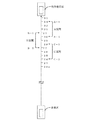
以下では、本発明の実施形態について、添付図面を参照して詳細に説明する。図1は、本発明の実施例1に係る車間距離警報装置の電気的構成を示すブロック図である。
この車間距離警報装置は自車両に搭載され、自車両から前方走行車までの距離を測定するための車間距離測定器1が備えられている。この車間距離測定器1としては、すでによく知られたレーザ光やミリ波を用いたレーダ方式のものや、画像処理によって車間距離を測定するものなどを使用することができる。
【0025】
車間距離測定器1の出力は、マイクロコンピュータ2へ与えられる。マイクロコンピュータ2にはそれ以外に、センサ4やブレーキセンサ6、車速センサ7等からの各出力が与えられる。センサ4は、アクセルペダル3の踏込み量や踏込み圧力に比例して出力信号が変化するもので、例えば、スロットルバルブの開く度合いを検出するスロットル開度センサ、吸気マニホールドに設置されエンジンに吸入される空気量を検出するエアフローメータ、吸気マニホールドの圧力を検出するバキュームセンサ、車速センサ、エンジン回転数センサ、あるいはアクセルペダル3に連結されているワイヤやリンクに取付けられた位置センサ、アクセルペダル3に取付けられたタッチセンサなどの、アクセルペダル3の操作によって出力信号が変化するものからの少なくとも一つ以上の信号が使用される。それ以外にも、アクセルペダル3の操作によって変化するバッテリー電圧をセンサ4からの出力信号値としてもよい。
【0026】
ブレーキセンサ6は、ブレーキペダル5が踏まれたことを検出するセンサである。車速センサ7は、例えばタイヤの回転軸に備えられたエンコーダホイールの回転量に応じた車輪速パルスを車速信号として出力するセンサである。この車速信号は、自動車にアンチロックブレーキシステムが備えられているときにはそれを使用してもよいし、速度計のための車速センサ7を用いてもよい。
【0027】
マイクロコンピュータ2では、上述の各センサや検出器からの信号に基づいて後述する処理を行い、その結果を表示装置8に表示させる。また、自車両と前方走行車とが衝突の恐れがある場合には警報器10を作動させ、ドライバに注意を与える。
さらに運転席の近傍には、ドライバが操作可能な操作パネル9や入力手段11がある。この操作パネル9により初期設定値等を変更するための操作が行え、また、入力手段11である押し釦スイッチを押すことで、ドライバが任意に後述する処理の実行が可能となっている。
【0028】
図2は、実施例1での車間距離警報装置の作用を説明するために、前方走行車と自車両との距離関係を示した図解図で、今例として、自車両に設置した車間距離測定器1により、前方走行車までの車間距離22mを測定したところを示す。
【0029】
図3は、実施例1での車間距離警報装置の操作状況を表示する表示装置8の液晶ディスプレイ12の画面を示したもので、13は車間距離測定器1で測定した前方走行車までの車間距離をデジタル表示する車間距離表示部で、図2の図解図より22の数値が表示される。14は警報距離表示部で、前方走行車と自車両とが衝突(追突)の可能性がある場合に警報器10の作動する時の車間距離がデジタル表示される。15は接近距離表示部で、前述の車間距離表示部13で表示される数値と、警報距離表示部14で表示される数値との差がデジタル表示され、測定されている現在の車間距離からあと何m接近すれば警報距離表示部14で表示されている車間距離になるかが示されることになる。
【0030】
16はセンサ4からの出力信号値に対応した値を示すスケールで、このスケール16の中央にはスケール16と色分けあるいは模様分けなどで強調表示されたゾーン部17が設けられている。このゾーン部17は後述するように車間距離警報装置の操作停止条件や、衝突の可能性を判断するために用いられるセンサ4からの出力信号値の基準範囲を示したものである。なお、このゾーン部17の幅(出力信号値の設定基準範囲)は、操作パネル9にある調節器(図示せず)により任意に増減でき、衝突の可能性の判別基準や、車間距離警報装置の操作停止条件をドライバの運転特性に合せられるようになっている。
18はセンサ4の出力信号値に対応した値を示す指針で、その出力信号値の変化にともないスケール16に沿って左右に動く。19は車速センサ7からの信号により自車速度をデジタル表示する速度表示部、20はエンジン回転数をバーグラフ表示するタコメータである。
【0031】
図4は、実施例1における車間距離警報装置の動作を示すフローチャート図で以下にその構成、作用について図1から図3を用いて説明する。
ステップS1にて、自車両に搭載した車間距離測定器1で前方走行車までの車間距離が測定され、図2で示した図解図よりその距離が22mであったとする。すると表示装置8の液晶ディスプレイ12の車間距離表示部13には22の数値が表示される。また、センサ4からの出力信号値も常時測定されており、マイクロコンピュータ2ではこの測定した出力信号値が所定時間(例えば2秒間)変化がなかったか否かを常に判別している(ステップS2)。例えば、センサ4からの出力信号の絶対値が30であったとすれば、ステップS2ではその30の値が所定時間同じであったか否かが調べられる。なお、この所定時間は操作パネル9にある調節器により任意に可変でき、ドライバの運転特性に合せられるようになっている。
【0032】
ステップS2で、センサ4からの出力信号値が所定時間変化がなかったことを検出すると、ステップS3では、マイクロコンピュータ2がその時のセンサ4からの出力信号値をもとにして出力信号値の基準範囲を設定記憶する。例えば、その時の出力信号値の絶対値が30でプラスマイナス5の差異の許容範囲が予め決められているのであれば、25から35の出力信号値の基準範囲が設定され、マイクロコンピュータ2内のメモリに記憶されることになる。さらに図3の液晶ディスプレイ12の表示画面で示すように、スケール16のゾーン部17やセンサ4からの出力信号値の変化を示す指針18が点灯表示される。この表示されたゾーン部17の幅(範囲)は、前述のマイクロコンピュータ2にて設定記憶された出力信号値の基準範囲に対応するものである。また、指針18が初めに表示される位置はこのゾーン部17の中央であるが、その後に測定されるセンサ4からの出力信号値の変化に応じてスケール16に沿って左右に動く。すなわち、ステップS2で所定時間変化しなかった時の出力信号値よりも高くなればスケール16の+側に、低くなれば−側に移動するが、指針18の位置がゾーン部17の範囲(出力信号値の設定基準範囲)外になった場合には、指針18の表示を消灯したり、あるいは指針18の色や模様などの表示態様を変化、例えば、ゾーン部17内に指針18がある場合はベタ表示の指針18であったものがゾーン部17より出ると輪郭線で画かれた指針18に変化させることでドライバが認知しやすいようにしている。また、ゾーン部17についても同じように消灯や表示態様を変化させるようにしてもよい。
【0033】
さらにステップS3では、ステップS2で所定時間センサ4からの出力信号値が変化しなかった時に測定された車間距離22mに対応して予め設定されている警報距離が、液晶ディスプレイ12の警報距離表示部14に表示される。この警報距離は、その時に測定された車間距離に対応してそれぞれ予め設定され、マイクロコンピュータ2内のメモリに記憶されているものである。すなわちステップS6での衝突の可能性の判定、ならびにその結果からステップS7で警報器10の作動する時の距離が表示されるものである。図2より、センサ4からの出力信号値が所定時間変化しなかった時に測定された車間距離22mに対し、マイクロコンピュータ2のメモリに予め記憶されている距離を例えば17m以内と設定している場合は、17の数値が警報距離表示部14に表示される。そしてこの警報距離表示部14に表示された数値は、作動中の車間距離警報装置のフローがクリア(途中のキャンセルも含む)されるまで変化しない。なお、各測定距離に対応して予め設定されている警報距離も操作パネル9にある調節器にて任意に可変でき、ドライバの運転特性に合せられるようになっている。
【0034】
また、警報距離表示部14に近接して設けられた接近距離表示部15には、前述の車間距離表示部13で表示されている数値22と、警報距離表示部14で表示されている数値17との差である5の数値が表示される。この接近距離表示部15で表示される数値により、車間距離があと5m接近すると警報距離の17mになり警報器10の作動することがドライバは容易に認知できることになる。もし、前方走行車と自車両との間に割込み車が入り、その距離が警報距離17m以内の14mであった場合は、接近距離表示部15には−3の数値が表示される。なお、この接近距離を車間距離表示部13で表示される距離、すなわちセンサ4からの出力信号値が所定時間変化しなかった時に測定された車間距離の遠近によってそれぞれ異なる距離に設定しておいてもよい。例えば、100mの遠距離の場合の接近距離を20mと長くとり、逆に15mの近距離では3mというように短く設定するものである。その後、前方走行車と自車両との距離が接近していくと、車間距離表示部13で表示されている22の数値は21、20、19…と減少していくが、警報距離表示部14で表示されている17の数値は作動中のフローがクリアになるまで変化しないため、接近距離表示部15で表示されている数値の5も4、3、2…と車間距離表示部13の数値に合せて減少していくことになる。
【0035】
そしてステップS4にて、前方走行車と自車両との車間距離が警報距離の17m以内になった時、すなわち接近距離表示部15で表示されている数値が0もしくは割込み車の測定によりマイナスの数値が表示された時はステップS5へ進み、その時のセンサ4からの出力信号値を読み込み、ステップS6で先にステップS3で設定記憶された出力信号値の基準範囲内か否かが調べられる。範囲内であれば前方走行車と自車両とが接近したにもかかわらず、自車両のドライバはアクセルペダル3を戻すなどの適切な処置をとっていないために衝突の可能性があると判断され、ステップS7にて警報器10より所定時間警報音が鳴り、液晶ディスプレイ12には警報ランプが点滅する。この警報ランプの点滅は、接近距離表示部15で表示された0、もしくは初めにマイナスで表示された時の数値を所定時間点滅させるようにしてもよい。
【0036】
なお、ステップS6での出力信号値が設定基準範囲内か否かは、液晶ディスプレイ12に表示されているスケール16のゾーン部17内に指針18が位置しているか否かによってドライバは目視にて確認することができる。また、このゾーン部17の範囲(出力信号値の設定基準範囲)は、前述したように操作パネル9にある調節器により任意に増減できるが、ステップS2で所定時間検出した時の出力信号値の大きさに応じて、予めその範囲が異なるように設定しておいてもよい。
【0037】
ステップS7で所定時間警報器10が働いたのち、あるいはステップS6で衝突の可能性を判断するために読み込まれた出力信号値が設定基準範囲外であった場合は、車間距離警報装置の動作はクリア(ステップS8)されてスタート時点に戻り、車間距離測定器1で測定されている距離やセンサ4からの出力信号値をもとにしてフローが再開される。
【0038】
このように実施例1では、衝突の可能性を自車両と前方走行車との車間距離が接近した時のドライバの反応から判断するもので、アクセルペダル3の操作によって出力信号が変化するセンサ4からの出力信号値をもとに、車間距離の接近にともない前記センサ4からの出力信号値の変化からドライバが適切な処置をとっているかを調べることで衝突の可能性を判別するものである。
なお、上述の実施例1では、センサ4からの出力信号値がステップS3で設定記憶された出力信号値の基準範囲外になった時(ステップS6)、すなわち指針18の位置がゾーン部17の範囲外になった時には、指針18やゾーン部17の表示を消灯したりあるいはその表示態様を変化させるようにしたが、それ以外にも、警報距離表示部14や接近距離表示部15に表示された数値の消灯や、あるいはその表示の大きさ、色、模様などの表示態様を変化させることで、ドライバにその状況を報知するようにしてもよい。
【0039】
次に実施例2の車間距離警報装置について、図5のフローチャート図をもとにして、その構成、作用について説明する。なお、電気的構成を示すブロック図や前方走行車と自車両との距離関係、ならびに表示装置8の液晶ディスプレイ12の画面構成については実施例1で述べた図1、図2、図3と全く同じのため同符号を付して示す。
図5のフローチャートにおいて、ステップT1にて、自車両に搭載した車間距離測定器1で前方走行車までの車間距離が測定され、図2で示したようにその距離が22mであったとする。すると液晶ディスプレイ12の車間距離表示部13には22の数値が表示される。マイクロコンピュータ2ではこの測定した車間距離22mをもとにして、前方走行車と自車両とが予め定められた時間(例えば2秒間)追従走行状態になったか否かを判別する(ステップT2)。なお、この予め定めた時間は、操作パネル9にある調節器により任意に可変でき、ドライバの運転特性に合せられるようになっている。
【0040】
また、この所定時間追従走行状態になったか否かの判別方法については、本願出願人により特願平5−101069号等にて提案したものを利用すればよい。これは車間距離測定器1で前方走行車までの車間距離を測定してから予め定めた時間経過後に測定された車間距離が、初めに測定された車間距離に対してどれだけ変化したかによって、あるいは、はじめに測定された車間距離の測定されている時間を計測し、その時間が予め定めた時間になったか否かによって前方走行車と自車両とが所定時間追従走行状態になったか否かを判別するものである。すなわち、測定された前方走行車との車間距離が所定時間変化しなかった場合に、所定時間追従走行状態になったと判断されものである。したがって、図5のフローチャートのステップT2、ステップT11の内容を、測定した車間距離が所定時間変化しなかったというように変更してもよい。これは後述する図7のフローチャート図のステップP2、ステップP8についても同様である。
【0041】
ステップT2で所定時間追従走行状態になったことを検出すると、マイクロコンピュータ2ではその時のセンサ4からの出力信号値を読み込み、その値をもとにして出力信号値の基準範囲が設定され、マイクロコンピュータ2内にある記憶手段に記憶される(ステップT3)。例えば、センサ4からの出力信号の絶対値が30であったとし、その値にプラスマイナス5の差異の許容範囲が予め決められているのであれば、25から35の出力信号値が基準範囲として設定され、マイクロコンピュータ2内のメモリに記憶される。そしてこの記憶された出力信号値の基準範囲に基づいて後述する衝突の可能性の判別が行われることになる。
【0042】
また、ステップT3では、ステップT2の追従走行状態になった時の車間距離22mに対応して予め設定されている警報距離が、図3の液晶ディスプレイ12の警報距離表示部14に表示される。この予め設定されている警報距離は、はじめに測定され所定時間追従走行状態を検出した時の車間距離に対応してそれぞれ予め設定されマイクロコンピュータ2内のメモリに記憶されているもので、すなわちステップT8での衝突(追突)の可能性の判定により、ステップT9で警報器10の作動する時の距離が表示されるものである。図2の図解図より、はじめに測定され所定時間追従走行状態であるか否かの判別に用いられた車間距離22mに対して、マイクロコンピュータ2のメモリに予め記憶させている距離を例えば17m以内と設定している場合は、17の数値が警報距離表示部14に表示される。そしてこの警報距離表示部14に表示された数値は、作動中のフローがクリア(途中のクリアも含む)されるまで変化しない。なお、この所定時間追従走行になった時の車間距離に対応して予め設定されている警報距離は、操作パネル9にある調節器により任意に可変できる。例えば、前述の22mの車間距離における警報距離17mを19mにと長くしたり、逆に15mに短くでき、ドライバの運転特性に合せられるようになっている。
【0043】
警報距離表示部14に近接して設けられた接近距離表示部15には、前述の車間距離表示部13で表示されている数値22と、警報距離表示部14で表示されている数値17との差である5の数値が表示される。この接近距離表示部15で表示される数値により、車間距離があと5m接近すると警報距離の17mになり警報器10の作動することがドライバは容易に認知できることになる。もし、前方走行車と自車両との間に割込み車が入り、その距離が警報距離17m以内の例えば14mであった場合は、接近距離表示部15には−3の数値が表示される。なお、この接近距離を車間距離表示部13で表示される距離、すなわち追従走行状態になった時の車間距離の遠近によって予めそれぞれ異なる距離に設定しておいてもよい。例えば、100mの遠距離の場合の接近距離を20mと長くとり、逆に15mの近距離の場合には3mというように短く設定するものである。
【0044】
さらにステップT3では、図3の液晶ディスプレイ12の表示画面で示すように、ゾーン部17とセンサ4からの出力信号値の変化を示す指針18が点灯表示される。このゾーン部17の幅(範囲)は、前述のマイクロコンピュータ2にて設定記憶された出力信号値の基準範囲(25から35)に相当するものである。また、指針18の表示位置ははじめに点灯した時はゾーン部17の中央であるがその後に測定されるセンサ4からの出力信号値の変化に応じてスケール16に沿って左右に動く。すなわち、ステップT2で所定時間追従走行状態になった時に測定されたセンサ4からの出力信号値よりも高くなればスケール16の+側に、低くなれば−側に移動する。
【0045】
そして、それ以降測定されるセンサ4からの出力信号値がこの設定基準範囲内であれば(ステップT4)、システムのフローはステップT6に進むが、もし、センサ4からの出力信号値がこの設定基準範囲外になった時、すなわち指針18の表示位置がゾーン部17の範囲外となった場合にはステップT5へ進み、ステップT3より表示された警報距離、接近距離の表示数値が消去、あるいは表示態様の変化(表示色、表示の大きさ、表示の模様などの変化)させることで、このままでは前方走行車と自車両とが警報距離内になっても警報器10から警報が発せられないことを、ドライバに認知しやすいようにしている。また、指針18の表示についてもその位置がゾーン部17の範囲より出た場合には、指針18の色大きさ、あるいは模様を変化、例えばゾーン部内に指針18がある場合はベタ表示であった指針18が、ゾーン部17より出ると輪郭線で描かれた指針18に変化させたり、またゾーン部17も同様に表示態様を変化させてもよい。なお、フローがステップT10でクリアになるまでに、センサ4からの出力信号値が設定基準範囲内(指針18の表示位置がゾーン部17内)になれば、再度これらを表示、あるいは表示態様が元に戻る。
【0046】
常に測定されているセンサ4からの出力信号値が設定基準範囲内にある状態で前方走行車と自車両との距離が接近していくと、車間距離表示部13で表示されている22の数値は21、20、19…と減少していくが、警報距離表示部14で表示されている17の数値は作動中のフローがクリアになるまで変化しないため、接近距離表示部15で表示されている数値の5も4、3、2…と車間距離表示部13の数値の変化に合せて減少していくことになる。
【0047】
そしてステップT6において、前方走行車と自車両との車間距離が警報距離の17m以内になった時、すなわち接近距離表示部15で表示される数値が0、もしくは割込み車の測定によりマイナスの数値が表示された時はステップT7へ進み、マイクロコンピュータ2ではその時のセンサ4からの出力信号値を読み込みステップT8にて先のステップT3で設定記憶された出力信号値の基準範囲内か否かが比較手段にて比較される。範囲内であれば前方走行車と自車両とが接近したにもかかわらず、自車両のドライバはアクセルペダル3を戻すなどの適切な処置をとっていないものと判断され、ステップT9にて衝突の危険をドライバに報知するため警報器10より所定時間警報音が鳴り、液晶ディスプレイ12には警報ランプが点滅する。
【0048】
ステップT9で所定時間警報器10が働いたのち、あるいはステップT8で測定されたセンサ4からの出力信号値が基準範囲外であった場合は、車間距離警報装置の動作はクリア(ステップT10)されてスタート時点に戻り、その時の測定車間距離をもとにしてフローが再開する。
【0049】
ステップT6で、車間距離測定器1で測定している前方走行車までの距離が警報距離内でなく、例えばその時の距離が20mであった場合はステップT11へ進み、この新たに測定された20mの距離をもとにしてマイクロコンピュータ2ではステップT2と同じように前方走行車と自車両とが所定時間追従走行状態になったか否かの判定が行われる。そして、この新たな測定距離20mで所定時間追従走行状態になると、ステップT12では、先のステップT3で実行されている記憶手段で記憶された出力信号値の基準範囲や、警報距離表示部14、接近距離表示部15に表示の各数値、ならびにゾーン部17や指針18の表示が消去される。
【0050】
そして再びステップT3へ戻り、20mの車間距離で新たに所定時間追従走行状態になった時のセンサ4からの出力信号値をもとにして出力信号値の基準範囲が新たに設定記憶され、警報距離表示部14にも20mの距離に対応して予め設定された警報距離、例えばそれが15mに設定してあれば15の数値が、それにともない接近距離表示部15には5の数値が表示される。またゾーン部17や指針18も再び表示される。それ以降のフローについては、前述した説明のことが繰り返される。
【0051】
なお、ステップT11で新たに所定時間追従走行状態を判断するための車間距離として、先に測定された22mに隣接する21mではなく20mとした理由は特願平9−41307号でも記載したように、前方走行車と自車両とが所定時間追従走行状態であると判断するのに、はじめに測定された距離を中心としてその前後の距離(例えばそれを各1mとしてもよいし、それ以外の距離であってもよい)も含めて追従走行状態を判定する距離に幅を持たせているからである。すなわち、ステップT1で測定された車間距離22mでその前後に各1mの幅を設定している場合は、21mから23mまでの距離がはじめに測定された22mの距離おける追従走行状態を判定する時の距離になる。そして、前方走行車と自車両とが接近して例えば20mの距離になった時の追従走行状態を判定する時の距離は、この20mの距離を中心として19mから21mの距離範囲となり、さらに接近した場合は18mの距離になった時の17mから19mの距離範囲となる。但し、ステップT2で一旦所定時間追従走行状態を検出した後に、さらにステップT11で新たに所定時間追従走行状態を検出するための車間距離は、新たに測定された車間距離を中心にして上述したように求められるため、それがステップT2と同じ22mであってもよいし、あるいはそれに隣接する23mや21mの距離であってもよいことになる。
【0052】
以上、実施例2について述べたが、上述の実施例2のステップT4では、センサ4からの出力信号値が瞬間的に設定基準範囲外となった場合でも警報距離や接近距離、あるいは指針18の表示が消去されたり、表示態様が変化(ステップT5)するようにしたが、瞬間的な出力信号値の基準範囲外でもってその度にステップT5を実行するとドライバにとっては煩わしいものとなってしまう可能性もある。そこでステップT4を、センサ4からの出力信号値が所定時間基準範囲外になったか否かによって判別するように、時間の要素を付加すればより効果的になる。
【0053】
さらにこの実施例2では、ステップT3以降に測定されるセンサ4からの出力信号値が設定基準範囲外(ステップT4)となった場合に、警報距離、接近距離や指針18の表示の消去、あるいは表示態様を変化(ステップT5)させたが、警報装置のフロー自体はそのまま続行している。そこで、ステップT4で出力信号値が基準範囲外となるとフローをステップT10へ進ませ、システムの動作を全てクリア(キャンセル)するシステムに変更するようにしてもよい。
【0054】
以上、この実施例2では、前方走行車と自車両とが所定時間追従走行状態を検出するごとに、その時の測定車間距離やセンサ4から出力信号値に基づいて車間距離警報装置の作動条件がその都度変更されるため、走行状況に的確に対応のできる衝突防止装置になる。また、センサ4からの出力信号値を常に監視しているため、それに連動するアクセルペダル3の操作、すなわち自車両のドライバの運転操作の変化によって車間距離警報装置が機能するか否かを、接近距離や警報距離の表示数値を消灯、あるいは表示数値の表示態様を変化させることで直ちに判断でき、装置の実用性を高めることが可能となる。
【0055】
次に実施例3について述べるが、この実施例3は本願出願人により特公平4−31074号ならびに特公平4−79551号にて提案した衝突予知装置に適用されるもので、先にこの衝突予知装置の概要について説明すると、車間距離測定器1で測定される前方走行車との距離に対し、第1基準距離とその第1基準距離よりも自車両に近い第2基準距離を予め設定しておき、前方走行車との距離が第1基準距離になったのを検出してから第2基準距離内の距離を検出するまでの時間から、または、第1基準距離の検出から所定時間後の測定距離が第2基準距離内になったか否かにより前方走行車と自車両との相対速度を求め、その相対速度が予め定めた速度以上の場合衝突の危険があると判断され、警報器10を作動させるというものである。
【0056】
図6はこの衝突予知装置の動作を説明するために、前方走行車と自車両との距離関係を示した図解図で、それぞれの距離に対し相対速度を求めるための基準距離が予め設定されている。例えばA区間、B区間、C区間…というように区分けしてマイクロコンピュータ2に予め設定記憶されている。そしてA区間においてA−1で表わされる第1基準距離を34m、それに対してA−2で表わされる第2基準距離を30mに、B区間ではB−1で表わされる第1基準距離を31m、B−2で表わされる第2基準距離を27mに、C区間ではC−1で表示の第1基準距離を28m、C−2で表示の第2基準距離を24mにと設定され、それぞれの区間での第1基準距離の検出から第2基準距離の検出をもとにしてマイクロコンピュータ2で相対速度が算出され衝突の有無が判定される。
【0057】
図7は実施例3におけるフローチャート図で、その動作説明を図6の距離関係をもとにして以下説明する。なお、液晶ディスプレイ12の画面構成は実施例2と同じのため、同符号を付して示す。ステップP1では、車間距離測定器1で前方走行車までの距離が測定され、その距離は液晶ディスプレイ12の車間距離表示部13に表示される。今、例として図6の図解図よりその距離が35mであるため35の数値が表示される。そしてその距離35mをもとにしてマイクロコンピュータ2では実施例2と同じように前方走行車と自車両とが所定時間追従走行状態になったか否かが調べられ(ステップP2)、追従走行状態である場合ステップP3へ進む。なお、追従走行状態を求める方法、ならびにその対象となる距離については実施例2の記載による。
【0058】
ステップP3では、所定時間追従走行状態と判定した時の測定距離35mに対して予め設定されている衝突予知装置の警報器10の作動する距離が液晶ディスプレイ12の警報距離表示部14に表示される。図6の図解図よりA区間の第2基準距離である30mの数値が表示され、この数値は作動中のシステムがクリアされるまで変化しない。但し、この例では警報距離と第2基準距離を同一として説明しているが、異なる距離、例えば警報距離を29mとしてもよい。すなわち相対速度を求めるための第2基準距離と警報器10の作動する距離とは必ずしも同一にする必要はないが、それらの距離関係については予め決めておく必要がある。
【0059】
さらに接近距離表示部15には車間距離表示部13で表示されている数値35と、警報距離表示部14で表示されている数値30との差である5の数値が表示され、現在測定されている距離35mからあと5m接近すると警報器10の作動する距離30mなるのが視認できる。その後に測定される車間距離により、実施例2で記載したように液晶ディスプレイ12で表示される各数値は変化し、さらにその測定距離をもとにして逐次追従走行状態になったか否かが調べられる(ステップP2、P8)。測定距離がA区間の第1基準距離34mを測定してから第2基準距離内の距離の測定によって求められる相対速度が、予め定めた速度以上の場合衝突の危険があると判断され(ステップP5)、ステップP6にて実施例2と同じように警報器10が作動した後、フローはクリア(ステップP7)しスタート時点に戻る。
【0060】
ステップP2、ステップP8にて、変化した測定距離にもとづいてマイクロコンピュータ2では前方走行車と自車両とが追従走行状態になっているかが逐次調べられるが、例えば、ステップP1での測定距離が35mであったものがその後の接近により32mの車間距離になり、しかもその距離にもとづいて予め定められた時間追従走行状態になった場合(ステップP8)はステップP9へ進み、先のステップP3より表示されている警報距離表示部14の30の数値と接近距離表示部15の数値が消去される。さらに衝突予知装置を作動させるためのA区間での相対速度の算出もクリアになる。それと同時に、今度は新たに追従走行状態を検出した時の距離である32mに対して予め設定されているB区間において衝突予知装置が働き、警報器10の作動する距離であるB区間の第2基準距離と同じに設定した27mの数値が警報距離表示部14に、また、接近距離表示部15には測定距離32mと警報距離27mとの差である5の数値がそれぞれ表示される。
【0061】
このように実施例3では、予め設定した2つの基準距離に前方走行車と自車両とが位置したことで求める相対速度により、衝突の可能性の有無を判断する衝突予知装置において、所定時間追従走行状態になった時に、その時の車間距離に対応して予め定められている衝突予知装置の警報器10の作動する距離、ならびに今測定されている車間距離と警報距離との差である接近距離を、液晶ディスプレイ12にそれぞれ表示するようにするものである。そして逐次測定される車間距離をもとに新たな車間距離で所定時間追従走行状態になったのを検出した場合には先の追従走行状態での衝突予知装置の作動する区間、ならびにその時の警報距離や接近距離の表示が消去(クリア)され、それと同時に、新たな車間距離に対応して予め定められている衝突予知装置の作動する区間にて衝突の有無が判定され、また、警報距離、接近距離の数値が液晶ディスプレイ12に表示されることになる。
【0062】
次に実施例4として、先に特開平4−340200号や公開技報98−6876号にて提案した車間距離報知装置での、本発明の車間距離表示装置の機能、作用について図8のフローチャート図をもとにして説明する。なお、電気的構成を示すブロック図や前方走行車と自車両との距離関係、ならびに液晶ディスプレイ12の画面構成については、前述の実施例1、実施例2で説明した図1、図2、図3と同じものであるため、同符号を付して示す。また、今測定されている車間距離と、警報距離、接近距離との関係についても実施例2と同じ内容にて説明する。
【0063】
図8の車間距離報知装置のフローチャート図において、ステップQ1にて車間距離測定器1で前方走行車までの距離を測定すると、液晶ディスプレイ12の車間距離表示部13にその距離が表示される。図2の図解図より22の数値が表示される(ステップQ2)。この距離測定時に、ドライバが手元付近にある入力手段11のスイッチをON(入力操作)すると(ステップQ3)、警報距離表示部14には、その時に測定された車間距離22mに対応して予め定められ、ステップQ7で警報器10の作動する警報距離の17が、接近距離表示部15には車間距離表示部13で表示の22と警報距離表示部14で表示の17との差である5の数値が表示される(ステップQ4)。なお、この測定距離22mとそれに対応する警報距離17mとの距離関係、すなわち接近距離5mの距離は、実施例2で記載したのと同じように操作パネル9にある調節器により任意に可変できようになっている。あるいは測定距離の遠近に応じて接近距離をそれぞれ異なるように予め設定しておくこともできる。
【0064】
前方走行車との車間距離が変化していくと、車間距離表示部13と接近距離表示部15で表示されている数値はそれに合せて変化するが、警報距離表示部14で表示されている17の数値は、実施例2と同じように作動中のフローがクリア(途中のキャンセルも含む)されるまで変化しない。さらに前方走行車と自車両とが接近してステップQ6の警報距離内になると、接近距離表示部15の数値は0を表示し、ステップQ7にて警報器10が入力手段11が解除(入力スイッチOFF)されるまで(ステップQ8)作動する。この時警報ランプは実施例2と同じように接近距離表示部15で表示された0の数値を点滅させてもよいし、あるいは別途に設けた表示灯を点滅させるようにしてもよい。さらには、ステップQ7の警報器10の作動は、ステップQ8での入力手段11の解除に係らず実施例2と同じように所定時間作動させた後、自動的にシステムをクリアしてはじめのスタート時点に戻るようにしてもよい。なお、ステップQ6で測定された前方走行車までの距離が割込み車により、接近距離表示部15の数値がマイナスで表示された場合も、ステップQ7での警報ランプは実施例2で記載したようにそのマイナスの数値が点滅される。
【0065】
ステップQ4でのシステム作動確認音の発生、ステップQ5での測定距離と警報距離との照合、あるいはそれ以降の各ステップの内容については、先に出願の特開平4−340200号や発明協会公開技報98−6876号、あるいは前述の実施例2にて開示しているのと同じのため、ここでの説明は繰り返さない。なお、この車間距離報知装置は、入力手段11の入力操作(スイッチON)が行われている間作動するもので、システムのフロー作動中に入力操作を停止(スイッチOFF)した場合は、作動中のフローはクリア(キャンセル)される。また、この入力手段11をリモコン式にして、マイクロコンピュータ2を内装した制御器(図示せず)に信号を送れるようにしておけば、ドライバの操作しやすい場所に入力手段11を設置することができる。
【0066】
このように実施例4では、ドライバが入力手段11の操作により任意に警報距離や接近距離を他の実施例と同じように液晶ディスプレイ12に表示させることができるため、実施例1から実施例3で述べたように、センサ4からの出力信号値が所定時間一定になるのを待ったり、前方走行車と自車両とが予め定められた時間追従走行状態になるのを待つ必要がなく、走行状況にすばやく対応のできる車間距離警報装置になる。したがって、実施例1から実施例3の車間距離警報装置や衝突予知装置にもこの入力手段11を設け、所定時間センサ4からも出力信号値が同じか否かを、あるいは所定時間追従走行になったか否かを判別するためのステップとは別途に、この入力手段11からの信号があった場合に次のステップ以降へ進むようにしておけば、これら各装置にも同じ効果を奏することができる。
【0067】
この発明の実施形態についての説明は以上の通りであるが、本発明は上述の実施例に限定されるものではなく、それぞれを組合わせた装置にしたり、種々変更することも可能である。例えば、実施例2では、ステップT3での出力信号値の基準範囲の設定記憶や警報距離、接近距離、ゾーン部17、指針18の表示の実行を、所定時間追従走行状態になった時(ステップT2、ステップT11)に行うようにしたが、このステップT2、ステップT11の内容を、実施例1で記載したように、センサ4からの出力信号値が所定時間一定になったか否かによって次のステップT3やステップT12が実行されるように変更してもよいことは明らかである。
【0068】
また、前方走行車と自車両との車間距離が接近すると、車間距離表示部13と接近距離表示部15で表示されている数値がそれに合せて減少し、逆に前方走行車と自車両とが離れていった場合は、表示の数値は増加していくことになるが、予め設定した距離以遠になると作動中のシステムを自動的にクリア(キャンセル)させるようにしてもよい。例えば、実施例2の所定時間追従走行状態になった時の車間距離22mに対応してシステムのフローがクリア(キャンセル)する距離を27m以遠とした場合には、前方走行車と自車両との車間距離がこの27mより遠ざかるとクリアされ、フローがスタート時点に戻るようにするものである。
【0069】
さらに表示装置の適用も上述の例で示した車間距離警報装置だけでなく、例えばすでに公知である前方走行車と自車両との車間距離が自車両の速度によって予め決められた安全車間距離になった時の検出に基づいて警報器10を作動させるようにした車間距離警報装置についても、前方走行車と自車両とが所定時間追従走行状態になった時に、自車両の速度によって予め設定された前記安全車間距離すなわち警報器10の作動する警報距離と、前方走行車までの車間距離と前記警報距離との差で示される接近距離を表示させるようにしてもよい。
また、接近距離表示部15に表示される数値についても、初めに表示される数値だけその表示色を他と異なるようにしたり、あるいは反転文字などの強調表示にしておけば、前方走行車との車間距離を維持ための指標としてより分かり易くなる。
【0070】
さらにこれら各実施例に、自車両の速度が予め定められた速度以上の場合や、センサ4からの出力信号値が予め定めた値以上の場合のみ車間距離警報装置や表示装置のシステムが動作するようにしたり、あるいは装置の作動中にブレーキセンサ6からの信号が所定時間継続してあったり、車間距離の測定が所定時間継続して測定されなかった場合には、フローがキャンセルするなどの各条件を付加しておけば、さらに信頼性のある交通事故防止装置なることを申し添えておく。そしてこの場合、なぜフローがキャンセルになったのか、あるいは警報器10が作動しなかったのかの理由をドライバに報知するために、液晶ディスプレイ12に該当するインジケータランプを点灯させるようにすればより効果的になる。例えば、ブレーキセンサ6からの信号によりフローがキャンセルになった場合は、ブレーキを図案化したマークを液晶ディスプレイ12に一定時間表示させるようにするものである。
【0071】
【発明の効果】
以上この発明によれば、前方走行車と自車両とが所定時間追従走行状態、すなわち測定された前方走行車との車間距離が所定時間変化しなかった後に、新たに所定時間追従走行状態を検出するごとに、あるいはセンサ4からの出力信号値が所定時間同じになったのを検出するごとに、その時の測定車間距離よって予め決めらた距離とセンサ4からの出力信号値に基づいて車間距離警報装置の作動条件がその都度変更されるため、刻々と変化する走行状況に的確に対応のできる自動車の衝突防止装置となる。
【0072】
また、表示装置では、センサ4からの出力信号値が所定時間同じになってからまたは前方走行車と自車両とが所定時間追従走行状態になってから、あるいはドライバによる入力手段の入力操作により、その時の測定車間距離、またはその時の自車両の速度に対応して予め設定されている警報器10の作動する距離や、それ以降に測定される車間距離と前記警報器10の作動する距離との差である接近距離を表示することで、あと何m接近すれば警報器10の作動する距離になるかが容易に認知できる。さらには、センサ4からの出力信号値の変化を示す指針18がスケール16のゾーン部17の範囲から外れたところに位置した時には、各表示灯の消灯やその表示態様を変化させることで衝突の有無の判定条件に合致しているか否かが簡単に視認できる。これらの表示機能によりドライバは前方走行車に対する車間距離警報装置の操作状況が一目瞭然となり、安全走行のための指標としてうかつな追突事故を防げるなどの交通安全に寄与できるものである。
【図面の簡単な説明】
【図1】この発明が適用される、各実施例の車間距離警報装置の電気的構成を示すブロック図である。
【図2】この発明が適用される、実施例1、2の車間距離警報装置、実施例4の車間距離報知装置の作用を説明するため、前方走行車と自車両との距離関係を示した図解図である。
【図3】本発明における表示装置の画面構成を、液晶ディスプレイに表示したところを示した図である。
【図4】この発明が適用される、実施例1の車間距離警報装置の動作を示すフローチャート図である。
【図5】この発明が適用される、実施例2の車間距離警報装置の動作を示すフローチャート図である。
【図6】この発明が適用される、実施例3の衝突予知装置の作用を説明するため、前方走行車と自車両との距離関係を示す図解図である。
【図7】この発明が適用される、実施例3の衝突予知装置の動作を示すフローチャート図である。
【図8】この発明が適用される、実施例4の車間距離報知装置の動作を示すフローチャート図である。
【符号の説明】
1 車間距離測定器
2 マイクロコンピュータ
3 アクセルペダル
4 センサ
5 ブレーキペダル
6 ブレーキセンサ
7 車速センサ
8 表示装置
9 操作パネル
10 警報器
11 入力手段(スイッチ)
12 液晶ディスプレイ
13 車間距離表示部
14 警報距離表示部
15 接近距離表示部
16 スケール
17 ゾーン部
18 指針[0001]
BACKGROUND OF THE INVENTION
The present invention is for preventing a collision such as a rear-end collision of a host vehicle with a front traveling vehicle based on a signal from a sensor linked to a speed control device of the host vehicle or measurement of an inter-vehicle distance from the host vehicle to a front traveling vehicle. Inter-vehicle distance alarmIn placeIt is related.
[0002]
[Prior art]
Conventionally, various devices have been devised for preventing rear-end collisions with vehicles traveling ahead using an inter-vehicle distance measuring device mounted on the host vehicle. The applicant of the present application also has a collision prediction device in Japanese Patent Publication No. 4-31074 and Japanese Patent Publication No. 4-79551, and a new rear-end collision warning in Japanese Patent Application No. 9-41307 and Japanese Institute of Technology Publication No. 98-6409. Regarding the apparatus and its inter-vehicle distance display method, Japanese Patent Laid-Open No. 4-340200 and published technical report 98-6876 propose an inter-vehicle distance notification device for notifying a change in the inter-vehicle distance.
[0003]
By the way, in the state where a plurality of vehicles are traveling safely, if the inter-vehicle distance between the host vehicle and the preceding traveling vehicle approaches, the driver of the host vehicle returns the accelerator pedal or steps on the brake pedal to reduce the speed of the host vehicle. The vehicle is decelerated and a measure corresponding to a change in the distance between the vehicle and the vehicle traveling ahead is used to prevent a collision (rear collision) accident. From this, it can be said that one of the causes of the collision (rear-end collision) is that the above-described series of operations is not performed, or the operation is delayed.
[0004]
[Problems to be solved by the invention]
However, in the conventional technology, there is a reliable device that can prevent a rear-end collision or the like by detecting it correctly when the above series of operations is not performed due to side-view driving or the like, or when there is a delay in the operation, It has not yet been put into practical use.
Therefore, an object of the present invention is to make the driver's reaction to the approach of the inter-vehicle distance based on the change in the output signal value from the sensor that generates a signal by the operation of the accelerator pedal when the host vehicle approaches the forward traveling vehicle. It is intended to provide a new inter-vehicle distance alarm device that investigates and issues an alarm when there is a possibility of a collision to prevent an accident.
Another object of the present invention is to propose an inter-vehicle distance alarm device that accurately corresponds to an ever-changing inter-vehicle distance, with respect to an improvement of a conventionally proposed alarm device. Furthermore, the display device optimal for these devices makes it possible to make the operation status clear at a glance, and to provide an inter-vehicle distance alarm device that is more practical and reliable as an index for safe driving.
[0005]
[Means for Solving the Problems]
The inter-vehicle distance alarm device according to the first aspect of the present invention is:An inter-vehicle distance measuring device mounted on the host vehicle, and a sensor whose output signal changes according to the operation of the accelerator pedal of the host vehicle.,The output signal value from the sensor became constant for a predetermined timeBySenSaReference range of output signal value based on output signal valueStorage means for storingIn the inter-vehicle distance measuring deviceTherefore,When the output signal value from the sensor becomes constant for a predetermined timeCarDistancePreset distance corresponding toIn response to measuring,Furthermore, the output signal value from the sensor isIn the storage meansAnd a means for determining the possibility of a collision based on whether or not the stored output signal value is within a reference range and outputting an alarm.
[0006]
The inter-vehicle distance alarm device according to the second aspect of the present invention measures the inter-vehicle distance to a forward vehicle by using an inter-vehicle distance measuring device mounted on the host vehicle, and the risk of collision based on detection of a preset inter-vehicle distance. An inter-vehicle distance alarm device that operates an alarm device for informing the vehicle, the inter-vehicle distance measured by the inter-vehicle distance measuring device, and the inter-vehicle distance between the forward traveling vehicle and the host vehicle becomes constant for a predetermined time, Including a display for displaying the distance that the alarm operates.
[0007]
The inter-vehicle distance alarm device according to a third aspect of the present invention measures the inter-vehicle distance to a forward vehicle by using an inter-vehicle distance measuring device mounted on the host vehicle, and the risk of collision based on the detection of a preset inter-vehicle distance. An inter-vehicle distance alarm device that operates an alarm device for informing the vehicle, the inter-vehicle distance measured by the inter-vehicle distance measuring device, and the inter-vehicle distance between the forward traveling vehicle and the host vehicle becomes constant for a predetermined time, Including a display for displaying a difference between a distance to a forward vehicle measured by the inter-vehicle distance measuring device and a distance at which the alarm operates..
[0008]
In one aspect of the inter-vehicle distance alarm device according to the second or third aspect, the distance at which the alarm is activated is set in advance corresponding to the inter-vehicle distance when the inter-vehicle distance becomes constant for a predetermined time. Distance.
[0009]
In another aspect of the inter-vehicle distance alarm device according to the second or third aspect, the distance at which the alarm operates is set in advance according to the speed of the host vehicle when the inter-vehicle distance becomes constant for a predetermined time. It is the set distance.
[0010]
Further, the inter-vehicle distance alarm device according to the second or third aspect includes a sensor in which an output signal is changed by an operation of an accelerator pedal of the host vehicle, and a sensor from when the inter-vehicle distance is constant for a predetermined time. Storage means for storing the reference range of the output signal value set based on the output signal value, and the output signal value from the sensor is out of the reference range of the output signal value stored in the storage means In some cases, further comprises means for erasing the display on the display.
[0011]
The inter-vehicle distance alarm device according to a fourth aspect of the present invention measures the inter-vehicle distance to a forward vehicle by using an inter-vehicle distance measuring device mounted on the host vehicle, and detects the danger of a collision based on detection of a preset inter-vehicle distance. An inter-vehicle distance alarm device that activates an alarm device for informing the vehicle of the vehicle, the sensor in which the output signal changes by the operation of the accelerator pedal of the host vehicle, and the output signal value from the sensor becomes constant for a predetermined time. And a display for displaying a distance at which the alarm operates.
[0012]
The inter-vehicle distance alarm device according to a fifth aspect of the present invention measures the inter-vehicle distance to a forward vehicle by using an inter-vehicle distance measuring device mounted on the host vehicle, and the risk of collision based on detection of a preset inter-vehicle distance. An inter-vehicle distance alarm device that activates an alarm device for informing the vehicle of the vehicle, the sensor in which the output signal changes by the operation of the accelerator pedal of the host vehicle, and the output signal value from the sensor becomes constant for a predetermined time. And a display for displaying a difference between the distance to the forward vehicle measured by the inter-vehicle distance measuring device and the distance at which the alarm operates.
[0013]
In one aspect of the inter-vehicle distance alarm device according to the fourth or fifth aspect, the distance that the alarm operates corresponds to the inter-vehicle distance when the output signal value from the sensor becomes constant for a predetermined time. Is a preset distance.
[0014]
Further, in another aspect of the inter-vehicle distance alarm device according to the fourth or fifth aspect, the distance at which the alarm is activated is the distance of the own vehicle when the output signal value from the sensor becomes constant for a predetermined time. It may be a distance set in advance corresponding to the speed.
[0015]
Further, the inter-vehicle distance alarm device according to the fourth or fifth aspect is an output signal set based on the output signal from the sensor when the output signal value of the sensor becomes constant for a predetermined time. Storage means for storing the reference range, and when the output signal value from the sensor is outside the reference range of the output signal value stored in the storage means, the display on the display is erased. And means.
[0016]
The inter-vehicle distance alarm device according to the sixth aspect of the present invention measures the inter-vehicle distance to a forward vehicle by using an inter-vehicle distance measuring device mounted on the host vehicle, and the risk of collision based on detection of a preset inter-vehicle distance. An inter-vehicle distance alarm device that operates an alarm device for informing the vehicle, a sensor that changes an output signal by operating an accelerator pedal of the host vehicle, and a forward traveling vehicle that is measured by the inter-vehicle distance measuring device, Storage means for storing a reference range of the output signal value set based on the output signal value from the sensor when the inter-vehicle distance becomes constant for a predetermined time, and the output signal stored in the storage means And a display for displaying a reference range of values.
[0017]
The inter-vehicle distance alarm device according to a seventh aspect of the present invention measures the inter-vehicle distance to a forward vehicle by using an inter-vehicle distance measuring device mounted on the host vehicle, and the risk of collision based on detection of a preset inter-vehicle distance. An inter-vehicle distance alarm device that activates an alarm device for informing the vehicle, and a sensor whose output signal changes due to an operation of an accelerator pedal of the host vehicle and when the output signal of the sensor becomes constant for a predetermined time Storage means for storing the reference range of the output signal value set based on the output signal value from the sensor, and a display for displaying the reference range of the output signal value stored in the storage means Including.
[0018]
Further, the inter-vehicle distance alarm device according to the sixth or seventh aspect may be configured so that the output signal value from the sensor is out of the reference range of the output signal value stored in the storage means. Further included is a means for erasing the display above.
[0019]
An inter-vehicle distance alarm device according to an eighth aspect of the present invention measures an inter-vehicle distance to a preceding vehicle by using an inter-vehicle distance measuring device mounted on the host vehicle, and detects a danger of a collision based on detection of a preset inter-vehicle distance. This is an inter-vehicle distance alarm device that operates an alarm device for informing the vehicle, and includes a display that displays a distance at which the alarm device operates according to an input signal from an input means installed in the host vehicle.
[0020]
The inter-vehicle distance alarm device according to a ninth aspect of the present invention measures the inter-vehicle distance to a forward vehicle by using an inter-vehicle distance measuring device mounted on the host vehicle, and the risk of collision based on detection of a preset inter-vehicle distance. An inter-vehicle distance alarm device that activates an alarm device for informing the vehicle, the distance to the forward traveling vehicle measured by the inter-vehicle distance measuring device according to an input signal from an input means installed in the own vehicle; It includes a display for displaying a difference from the operating distance of the alarm device.
[0021]
In one aspect of the inter-vehicle distance alarm device according to the eighth or ninth aspect, the distance that the alarm operates is a distance set in advance corresponding to the inter-vehicle distance at the time of signal input from the input means. is there.
[0022]
In another aspect of the inter-vehicle distance measuring apparatus according to the eighth or ninth aspect, the distance at which the alarm operates is set in advance corresponding to the speed of the host vehicle when a signal is input from the input means. Distance.
[0023]
The inter-vehicle distance alarm device according to a tenth aspect of the present invention measures the inter-vehicle distance to a forward vehicle by using an inter-vehicle distance measuring device mounted on the host vehicle, and the risk of collision based on the detection of a preset inter-vehicle distance. An inter-vehicle distance alarm device that operates an alarm device for informing the vehicle, a sensor that changes an output signal by operating an accelerator pedal of the host vehicle, and a forward traveling vehicle that is measured by the inter-vehicle distance measuring device, Storage means for storing a reference range of the output signal value set based on the output signal value from the sensor when the inter-vehicle distance is constant for a predetermined time, and measured by the inter-vehicle distance measuring device. And a means for erasing the reference range of the output signal value stored in the storage means based on the fact that the inter-vehicle distance with the preceding traveling vehicle has become constant for a predetermined time.
An inter-vehicle distance alarm device according to an eleventh aspect of the present invention measures the inter-vehicle distance to a forward vehicle by using an inter-vehicle distance measuring device mounted on the host vehicle, and the risk of collision based on detection of a predetermined inter-vehicle distance. An inter-vehicle distance alarm device that activates an alarm device for informing the vehicle, and a sensor whose output signal changes due to an operation of an accelerator pedal of the host vehicle, and an output signal value from the sensor becomes constant for a predetermined time. Storage means for storing the reference range of the output signal value set based on the output signal value from the sensor at the time, and the output signal value from the sensor is newly constant for a predetermined time. And a means for erasing the reference range of the output signal value stored in the storage means.
The inter-vehicle distance alarm device according to the twelfth aspect of the present invention measures the inter-vehicle distance to the vehicle ahead by using an inter-vehicle distance measuring device mounted on the host vehicle, and detects the risk of collision based on the detection of the preset inter-vehicle distance. An inter-vehicle distance alarm device that activates an alarm device for informing the vehicle, a vehicle that travels forward measured by the inter-vehicle distance measuring device and a sensor that changes an output signal by operating an accelerator pedal of the host vehicle Storage means for storing a reference range of the output signal value set based on the output signal value from the sensor when the inter-vehicle distance is constant for a predetermined time, and the output stored in the storage means Based on the fact that the inter-vehicle distance measured with the indicator for displaying the reference range of the signal value and the preceding vehicle measured by the inter-vehicle distance measuring device becomes constant for a predetermined time, the display on the indicator is displayed. Erase And an order of means.
The inter-vehicle distance alarm device according to a thirteenth aspect of the present invention measures the inter-vehicle distance to a forward vehicle by using an inter-vehicle distance measuring device mounted on the host vehicle, and the risk of collision based on the detection of a preset inter-vehicle distance. An inter-vehicle distance alarm device that activates an alarm device for informing the vehicle of the vehicle, the sensor in which the output signal changes by the operation of the accelerator pedal of the host vehicle, and the output signal value from the sensor becomes constant for a predetermined time. Storage means for storing the reference range of the output signal value set based on the output signal value from the sensor, and a display for displaying the reference range of the output signal value stored in the storage means And means for erasing the display on the display unit based on the fact that the output signal from the sensor is newly constant for a predetermined time.
According to a fourteenth aspect of the present invention, an inter-vehicle distance alarm device measures an inter-vehicle distance to a forward vehicle by using an inter-vehicle distance measuring device mounted on the host vehicle, and detects a collision risk based on detection of a preset inter-vehicle distance. An inter-vehicle distance alarm device that operates an alarm device for informing the vehicle, the inter-vehicle distance measured by the inter-vehicle distance measuring device, and the inter-vehicle distance between the forward traveling vehicle and the host vehicle becomes constant for a predetermined time, Based on the fact that the inter-vehicle distance between the vehicle traveling ahead and the host vehicle, which is measured by the inter-vehicle distance measuring device, is constant for a predetermined time, which is measured by the inter-vehicle distance measuring device, is displayed. Means for erasing the display on the vessel.
According to a fifteenth aspect of the present invention, an inter-vehicle distance alarm device measures an inter-vehicle distance to a forward vehicle by using an inter-vehicle distance measuring device mounted on the host vehicle, and detects a danger of a collision based on detection of a predetermined inter-vehicle distance. An inter-vehicle distance alarm device that operates an alarm device for informing the vehicle, the inter-vehicle distance measured by the inter-vehicle distance measuring device, and the inter-vehicle distance between the forward traveling vehicle and the host vehicle becomes constant for a predetermined time, A display for displaying a difference between a distance to a forward traveling vehicle measured by the inter-vehicle distance measuring device and a distance at which the alarm is activated; and a forward traveling vehicle and the own vehicle measured by the inter-vehicle distance measuring device; Means for erasing the display on the display unit based on the fact that the inter-vehicle distance has become constant for a predetermined time.
The inter-vehicle distance alarm device according to the sixteenth aspect of the present invention measures the inter-vehicle distance to a forward vehicle by using an inter-vehicle distance measuring device mounted on the host vehicle, and the risk of collision based on detection of a preset inter-vehicle distance. An inter-vehicle distance alarm device that activates an alarm device for informing the vehicle of the vehicle, the sensor in which the output signal changes by the operation of the accelerator pedal of the host vehicle, and the output signal value from the sensor becomes constant for a predetermined time. And a means for erasing the display on the display based on the fact that the output signal value from the sensor is newly constant for a predetermined time. Further included.
The inter-vehicle distance alarm device according to the seventeenth aspect of the present invention measures the inter-vehicle distance to a forward vehicle by using an inter-vehicle distance measuring device mounted on the host vehicle, and detects the danger of collision based on detection of a preset inter-vehicle distance. An inter-vehicle distance alarm device that activates an alarm device for informing the vehicle of the vehicle, the sensor in which the output signal changes by the operation of the accelerator pedal of the host vehicle, and the output signal value from the sensor becomes constant for a predetermined time. And a display for displaying the difference between the distance to the preceding vehicle measured by the inter-vehicle distance measuring device and the distance at which the alarm operates, and the output signal value from the sensor is newly made constant for a predetermined time. And means for erasing the display on the display based on the fact that
[0024]
DETAILED DESCRIPTION OF THE INVENTION
Hereinafter, embodiments of the present invention will be described in detail with reference to the accompanying drawings. FIG. 1 is a block diagram illustrating an electrical configuration of the inter-vehicle distance alarm device according to the first embodiment of the present invention.
This inter-vehicle distance alarm device is mounted on the host vehicle and includes an inter-vehicle
[0025]
The output of the inter-vehicle
[0026]
The
[0027]
In the
Further, in the vicinity of the driver's seat, there are an operation panel 9 and input means 11 that can be operated by the driver. An operation for changing an initial setting value or the like can be performed by the operation panel 9, and a driver can arbitrarily execute processing to be described later by pressing a push button switch as the input unit 11.
[0028]
FIG. 2 is an illustrative view showing a distance relationship between the forward traveling vehicle and the host vehicle in order to explain the operation of the inter-vehicle distance alarm device in the first embodiment. As an example, the inter-vehicle distance measurement installed in the host vehicle is illustrated. The place where the inter-vehicle distance 22m to the forward traveling vehicle is measured by the
[0029]
FIG. 3 shows a screen of the
[0030]
[0031]
FIG. 4 is a flowchart showing the operation of the inter-vehicle distance warning device in the first embodiment, and the configuration and operation will be described below with reference to FIGS.
In step S1, it is assumed that the inter-vehicle distance to the forward traveling vehicle is measured by the inter-vehicle
[0032]
When it is detected in step S2 that the output signal value from the
[0033]
Further, in step S3, a warning distance set in advance corresponding to the inter-vehicle distance 22m measured when the output signal value from the
[0034]
The approach
[0035]
In step S4, when the inter-vehicle distance between the forward vehicle and the host vehicle is within 17m of the warning distance, that is, the numerical value displayed on the approach
[0036]
Whether or not the output signal value in step S6 is within the set reference range depends on whether or not the
[0037]
After the alarm device 10 is activated for a predetermined time in step S7 or when the output signal value read in order to determine the possibility of a collision in step S6 is outside the set reference range, the operation of the inter-vehicle distance alarm device is as follows. After clearing (step S8) and returning to the start time, the flow is resumed based on the distance measured by the inter-vehicle
[0038]
As described above, in the first embodiment, the possibility of a collision is determined based on the driver's reaction when the distance between the host vehicle and the vehicle ahead is approaching, and the
In the above-described first embodiment, when the output signal value from the
[0039]
Next, the configuration and operation of the inter-vehicle distance alarm device of the second embodiment will be described based on the flowchart of FIG. The block diagram showing the electrical configuration, the distance relationship between the vehicle in front and the host vehicle, and the screen configuration of the
In the flowchart of FIG. 5, it is assumed that the inter-vehicle distance to the forward traveling vehicle is measured by the inter-vehicle
[0040]
In addition, as a method for determining whether or not the vehicle has been in the follow-up state for the predetermined time, a method proposed in Japanese Patent Application No. 5-101069 by the applicant of the present application may be used. This is based on how much the inter-vehicle distance measured after a predetermined time has elapsed from the time when the inter-vehicle
[0041]
When it is detected in step T2 that the vehicle has been in the follow-up state for a predetermined time, the
[0042]
Further, in step T3, a warning distance set in advance corresponding to the inter-vehicle distance 22m when the follow-up running state in step T2 is reached is displayed on the warning
[0043]
An approach
[0044]
Further, in step T3, as shown in the display screen of the
[0045]
If the output signal value from the
[0046]
When the distance between the vehicle traveling ahead and the host vehicle approaches while the output signal value from the
[0047]
In step T6, when the inter-vehicle distance between the forward vehicle and the host vehicle is within 17 m of the alarm distance, that is, the numerical value displayed on the approach
[0048]
After the alarm device 10 is activated for a predetermined time in step T9, or when the output signal value from the
[0049]
In step T6, when the distance to the forward vehicle measured by the inter-vehicle
[0050]
Then, the process returns to step T3 again, and the reference range of the output signal value is newly set and stored on the basis of the output signal value from the
[0051]
The reason why the distance between the vehicles for newly determining the following running state for the predetermined time at step T11 is 20 m instead of 21 m adjacent to the previously measured 22 m is as described in Japanese Patent Application No. 9-41307. In order to determine that the forward traveling vehicle and the host vehicle are in the following state for the predetermined time, the distance measured before and after the distance measured at the beginning (for example, it may be 1 m each, or at other distances) This is because the distance for determining the follow-up traveling state including a range may be widened. That is, when the distance between the vehicles is 22m measured at step T1 and the width of each 1m is set before and after the distance, the following traveling state is determined when the distance from 21m to 23m is first measured at the distance of 22m. Become a distance. Then, the distance for determining the following traveling state when the forward traveling vehicle and the host vehicle approach each other and reach a distance of 20 m, for example, is a distance range of 19 m to 21 m centering on the distance of 20 m, and further closer In this case, the distance range is 17 m to 19 m when the distance is 18 m. However, after detecting the tracking state following the predetermined time at step T2, the inter-vehicle distance for newly detecting the tracking state following the predetermined time at step T11 is as described above centering on the newly measured inter-vehicle distance. Therefore, it may be 22 m, which is the same as step T2, or may be a distance of 23 m or 21 m adjacent thereto.
[0052]
As described above, the second embodiment has been described. In step T4 of the second embodiment described above, even when the output signal value from the
[0053]
Further, in the second embodiment, when the output signal value from the
[0054]
As described above, in the second embodiment, every time the forward traveling vehicle and the host vehicle detect the following traveling state for a predetermined time, the operating condition of the inter-vehicle distance alarm device is based on the measured inter-vehicle distance and the output signal value from the
[0055]
Next, a third embodiment will be described. This third embodiment is applied to the collision prediction apparatus proposed in Japanese Patent Publication No. 4-31074 and Japanese Patent Publication No. 4-79551 by the applicant of the present application. The outline of the apparatus will be described. The first reference distance and the second reference distance closer to the host vehicle than the first reference distance are set in advance with respect to the distance from the forward traveling vehicle measured by the inter-vehicle
[0056]
FIG. 6 is an illustrative view showing the distance relationship between the forward traveling vehicle and the host vehicle in order to explain the operation of the collision prediction apparatus, and a reference distance for obtaining a relative speed is preset for each distance. Yes. For example, the
[0057]
FIG. 7 is a flowchart in the third embodiment, and the operation thereof will be described below based on the distance relationship of FIG. Since the screen configuration of the
[0058]
In step P3, the distance that the alarm device 10 of the collision prediction device that is set in advance for the measurement distance 35 m when it is determined that the vehicle follows the predetermined time is displayed on the alarm
[0059]
Further, the approach
[0060]
In step P2 and step P8, based on the changed measurement distance, the
[0061]
As described above, in the third embodiment, in the collision prediction device that determines the possibility of a collision based on the relative speed obtained when the forward traveling vehicle and the host vehicle are positioned at two preset reference distances, a predetermined time follow-up is performed. The distance at which the alarm device 10 of the collision prediction device is activated corresponding to the distance between the vehicles at the time when the vehicle is in the running state, and the approach distance that is the difference between the currently measured distance between the vehicles and the warning distance. Are respectively displayed on the
[0062]
Next, as a fourth embodiment, the function and operation of the inter-vehicle distance display device of the present invention in the inter-vehicle distance notification device previously proposed in Japanese Patent Laid-Open No. 4-340200 and published technical report 98-6876 is shown in the flowchart of FIG. This will be described with reference to the drawings. The block diagram showing the electrical configuration, the distance relationship between the vehicle in front and the host vehicle, and the screen configuration of the
[0063]
In the flowchart of the inter-vehicle distance notification device in FIG. 8, when the distance to the vehicle ahead is measured by the inter-vehicle
[0064]
As the inter-vehicle distance with the forward traveling vehicle changes, the numerical values displayed on the inter-vehicle
[0065]
For generating the system operation confirmation sound in step Q4, collating the measured distance with the alarm distance in step Q5, or the contents of each step thereafter, see Japanese Patent Application Laid-Open No. Hei 4-340200 or the invention association published technology. Since it is the same as that disclosed in No. 98-6876 or the above-described
[0066]
As described above, in the fourth embodiment, the driver can arbitrarily display the alarm distance and the approach distance on the
[0067]
The description of the embodiment of the present invention is as described above. However, the present invention is not limited to the above-described embodiments, and can be combined with each other or variously modified. For example, in the second embodiment, when the setting of the reference range of the output signal value in step T3 and the display of the alarm distance, the approach distance, the
[0068]
In addition, when the inter-vehicle distance between the forward traveling vehicle and the host vehicle approaches, the numerical values displayed on the inter-vehicle
[0069]
Further, the display device is applied not only to the inter-vehicle distance alarm device shown in the above-described example, but also, for example, the inter-vehicle distance between the forward traveling vehicle and the host vehicle that is already known becomes a safe inter-vehicle distance determined in advance by the speed of the host vehicle. The inter-vehicle distance alarm device that activates the alarm device 10 based on the detection at the time is also set in advance according to the speed of the own vehicle when the forward traveling vehicle and the own vehicle are in a follow-up traveling state for a predetermined time. You may make it display the approach distance shown by the difference of the said safe distance between vehicles, ie, the alarm distance which the alarm device 10 act | operates, the inter-vehicle distance to a forward vehicle, and the said alarm distance.
Also, the numerical value displayed on the approach
[0070]
Furthermore, in each of these embodiments, the inter-vehicle distance alarm device and the display system operate only when the speed of the host vehicle is equal to or higher than a predetermined speed or when the output signal value from the
[0071]
【The invention's effect】
As described above, according to the present invention, the forward traveling vehicle and the host vehicle follow the predetermined traveling state, that is, after the measured inter-vehicle distance from the preceding traveling vehicle does not change for the predetermined time, a new predetermined traveling state following state is detected. Every time when the output signal value from the
[0072]
Further, in the display device, after the output signal value from the
[Brief description of the drawings]
FIG. 1 is a block diagram showing an electrical configuration of an inter-vehicle distance alarm device of each embodiment to which the present invention is applied.
FIG. 2 shows a distance relationship between a forward traveling vehicle and the host vehicle in order to explain the operation of the inter-vehicle distance alarm device of
FIG. 3 is a diagram showing a screen configuration of a display device according to the present invention displayed on a liquid crystal display.
FIG. 4 is a flowchart showing the operation of the inter-vehicle distance alarm device of the first embodiment to which the present invention is applied.
FIG. 5 is a flowchart showing the operation of the inter-vehicle distance alarm device of the second embodiment to which the present invention is applied.
FIG. 6 is an illustrative view showing a distance relationship between a forward traveling vehicle and the own vehicle in order to explain the operation of the collision prediction apparatus according to the third embodiment to which the present invention is applied;
FIG. 7 is a flowchart showing the operation of the collision prediction apparatus according to the third embodiment to which the present invention is applied.
FIG. 8 is a flowchart showing the operation of the inter-vehicle distance notification device of the fourth embodiment to which the present invention is applied.
[Explanation of symbols]
1 Inter-vehicle distance measuring device
2 Microcomputer
3 Accelerator pedal
4 Sensor
5 Brake pedal
6 Brake sensor
7 Vehicle speed sensor
8 display devices
9 Operation panel
10 Alarm
11 Input means (switch)
12 Liquid crystal display
13 Inter-vehicle distance display
14 Alarm distance display
15 Approach distance display
16 scale
17 Zone
18 Guidelines
Claims (12)
Priority Applications (4)
| Application Number | Priority Date | Filing Date | Title |
|---|---|---|---|
| JP2000399361A JP4201155B2 (en) | 2000-11-22 | 2000-11-22 | Inter-vehicle distance alarm device |
| US09/987,254 US6522969B2 (en) | 2000-11-22 | 2001-11-14 | Following distance displaying apparatus that changes alarming display according to operating states |
| DE10156721A DE10156721A1 (en) | 2000-11-22 | 2001-11-19 | Distance-between-vehicles warning device determines possibility of collision based on distance measured, whether sensor value remains unchanged, and reference value |
| CN01139464A CN1359093A (en) | 2000-11-22 | 2001-11-22 | Tracking distance indicator capable of changing alarm display according to operation state |
Applications Claiming Priority (1)
| Application Number | Priority Date | Filing Date | Title |
|---|---|---|---|
| JP2000399361A JP4201155B2 (en) | 2000-11-22 | 2000-11-22 | Inter-vehicle distance alarm device |
Publications (3)
| Publication Number | Publication Date |
|---|---|
| JP2002163798A JP2002163798A (en) | 2002-06-07 |
| JP2002163798A5 JP2002163798A5 (en) | 2007-12-06 |
| JP4201155B2 true JP4201155B2 (en) | 2008-12-24 |
Family
ID=18864150
Family Applications (1)
| Application Number | Title | Priority Date | Filing Date |
|---|---|---|---|
| JP2000399361A Expired - Fee Related JP4201155B2 (en) | 2000-11-22 | 2000-11-22 | Inter-vehicle distance alarm device |
Country Status (4)
| Country | Link |
|---|---|
| US (1) | US6522969B2 (en) |
| JP (1) | JP4201155B2 (en) |
| CN (1) | CN1359093A (en) |
| DE (1) | DE10156721A1 (en) |
Families Citing this family (91)
| Publication number | Priority date | Publication date | Assignee | Title |
|---|---|---|---|---|
| US5910854A (en) | 1993-02-26 | 1999-06-08 | Donnelly Corporation | Electrochromic polymeric solid films, manufacturing electrochromic devices using such solid films, and processes for making such solid films and devices |
| US5668663A (en) | 1994-05-05 | 1997-09-16 | Donnelly Corporation | Electrochromic mirrors and devices |
| US6891563B2 (en) | 1996-05-22 | 2005-05-10 | Donnelly Corporation | Vehicular vision system |
| US6124886A (en) | 1997-08-25 | 2000-09-26 | Donnelly Corporation | Modular rearview mirror assembly |
| US6326613B1 (en) | 1998-01-07 | 2001-12-04 | Donnelly Corporation | Vehicle interior mirror assembly adapted for containing a rain sensor |
| US6172613B1 (en) | 1998-02-18 | 2001-01-09 | Donnelly Corporation | Rearview mirror assembly incorporating vehicle information display |
| US8294975B2 (en) | 1997-08-25 | 2012-10-23 | Donnelly Corporation | Automotive rearview mirror assembly |
| US6445287B1 (en) | 2000-02-28 | 2002-09-03 | Donnelly Corporation | Tire inflation assistance monitoring system |
| US8288711B2 (en) | 1998-01-07 | 2012-10-16 | Donnelly Corporation | Interior rearview mirror system with forwardly-viewing camera and a control |
| US6477464B2 (en) | 2000-03-09 | 2002-11-05 | Donnelly Corporation | Complete mirror-based global-positioning system (GPS) navigation solution |
| US6693517B2 (en) | 2000-04-21 | 2004-02-17 | Donnelly Corporation | Vehicle mirror assembly communicating wirelessly with vehicle accessories and occupants |
| US6329925B1 (en) | 1999-11-24 | 2001-12-11 | Donnelly Corporation | Rearview mirror assembly with added feature modular display |
| US7004593B2 (en) | 2002-06-06 | 2006-02-28 | Donnelly Corporation | Interior rearview mirror system with compass |
| US7370983B2 (en) | 2000-03-02 | 2008-05-13 | Donnelly Corporation | Interior mirror assembly with display |
| US7167796B2 (en) | 2000-03-09 | 2007-01-23 | Donnelly Corporation | Vehicle navigation system for use with a telematics system |
| WO2007053710A2 (en) | 2005-11-01 | 2007-05-10 | Donnelly Corporation | Interior rearview mirror with display |
| AU2001243285A1 (en) * | 2000-03-02 | 2001-09-12 | Donnelly Corporation | Video mirror systems incorporating an accessory module |
| US7581859B2 (en) | 2005-09-14 | 2009-09-01 | Donnelly Corp. | Display device for exterior rearview mirror |
| US7255451B2 (en) | 2002-09-20 | 2007-08-14 | Donnelly Corporation | Electro-optic mirror cell |
| EP1363810B1 (en) | 2001-01-23 | 2007-05-30 | Donnelly Corporation | Improved vehicular lighting system |
| JP3933427B2 (en) * | 2001-09-20 | 2007-06-20 | 本田技研工業株式会社 | Vehicle hood control device |
| US6918674B2 (en) | 2002-05-03 | 2005-07-19 | Donnelly Corporation | Vehicle rearview mirror system |
| US7329013B2 (en) | 2002-06-06 | 2008-02-12 | Donnelly Corporation | Interior rearview mirror system with compass |
| AU2003278863A1 (en) | 2002-09-20 | 2004-04-08 | Donnelly Corporation | Mirror reflective element assembly |
| WO2004103772A2 (en) | 2003-05-19 | 2004-12-02 | Donnelly Corporation | Mirror assembly for vehicle |
| US7310177B2 (en) | 2002-09-20 | 2007-12-18 | Donnelly Corporation | Electro-optic reflective element assembly |
| US7446924B2 (en) | 2003-10-02 | 2008-11-04 | Donnelly Corporation | Mirror reflective element assembly including electronic component |
| US7308341B2 (en) | 2003-10-14 | 2007-12-11 | Donnelly Corporation | Vehicle communication system |
| JP2005173929A (en) * | 2003-12-10 | 2005-06-30 | Denso Corp | Device for determining awakening degree |
| JP4544452B2 (en) * | 2004-01-15 | 2010-09-15 | 本田技研工業株式会社 | Motorcycle equipped with a display device |
| DE102004046360B4 (en) * | 2004-09-24 | 2014-03-27 | Daimler Ag | Motor vehicle with a preventive protection system |
| ITMI20042359A1 (en) * | 2004-12-10 | 2005-03-10 | Ec Elettronica S R L | AUXILIARY EQUIPMENT FOR DRIVING A VEHICLE IN RELATION TO THE MAINTENANCE OF THE SAFETY DISTANCE AFTER A VEHICLE OR OBSTACLE WHICH PREVENTS |
| ATE517368T1 (en) | 2005-05-16 | 2011-08-15 | Donnelly Corp | VEHICLE MIRROR ARRANGEMENT WITH CHARACTER ON THE REFLECTIVE PART |
| WO2007023668A1 (en) * | 2005-08-24 | 2007-03-01 | Hino Motors, Ltd. | Automatic brake control device |
| CN101401024B (en) | 2006-03-09 | 2016-03-16 | 金泰克斯公司 | Comprise the vehicle rearview assembly of high intensity display |
| JP4765766B2 (en) * | 2006-05-23 | 2011-09-07 | 日産自動車株式会社 | VEHICLE DRIVE OPERATION ASSISTANCE DEVICE AND VEHICLE WITH VEHICLE DRIVE OPERATION ASSISTANCE DEVICE |
| US8035320B2 (en) | 2007-04-20 | 2011-10-11 | Sibert W Olin | Illumination control network |
| DE102007020392A1 (en) * | 2007-04-30 | 2008-11-06 | Multivac Sepp Haggenmüller Gmbh & Co. Kg | Apparatus and method for displaying measured values and shrink tunnels for a packaging machine or packaging machine with such a device |
| US8154418B2 (en) | 2008-03-31 | 2012-04-10 | Magna Mirrors Of America, Inc. | Interior rearview mirror system |
| EP2258588B1 (en) * | 2008-04-01 | 2014-12-10 | Crambo, S.a. | Device for monitoring vehicle driving |
| EP2319031A4 (en) * | 2008-07-01 | 2014-01-08 | Kpit Technologies Ltd | Sensor system for vehicle safety |
| US9487144B2 (en) | 2008-10-16 | 2016-11-08 | Magna Mirrors Of America, Inc. | Interior mirror assembly with display |
| BRMU9002606U2 (en) * | 2009-01-15 | 2013-12-17 | Hcs Kablolama Sistemleri San Ve Tic A S | IMPROVED WIRING METHOD AND SYSTEM FOR MONITORING AND MANAGING PHYSICALLY CONNECTED DEVICES IN A DATA NETWORK. |
| CN102079267A (en) * | 2010-12-30 | 2011-06-01 | 大连理工大学 | Controller area network (CAN) bus-based light emitting diode (LED) high mount stop lamp intelligent control system |
| JP5263312B2 (en) * | 2011-02-03 | 2013-08-14 | トヨタ自動車株式会社 | Traffic jam judging device and vehicle control device |
| WO2012143926A1 (en) | 2011-04-18 | 2012-10-26 | HCS KABLOLAMA SISTEMLERI SAN. ve TIC.A.S. | A method of analyzing patching among panels |
| JP5905088B2 (en) * | 2011-06-17 | 2016-04-20 | ローベルト ボッシュ ゲゼルシャフト ミット ベシュレンクテル ハフツング | Method and display device for displaying the running state of a vehicle, and computer program product corresponding thereto |
| JP5975613B2 (en) * | 2011-09-06 | 2016-08-23 | 矢崎総業株式会社 | Image display speedometer |
| JP5941257B2 (en) * | 2011-09-07 | 2016-06-29 | 矢崎総業株式会社 | Speed display device and speed display method |
| US20130187771A1 (en) * | 2012-01-23 | 2013-07-25 | Ariel Inventions, Llc | System and method for display of vehicular separation distance |
| US8879139B2 (en) | 2012-04-24 | 2014-11-04 | Gentex Corporation | Display mirror assembly |
| US8610595B1 (en) * | 2012-07-19 | 2013-12-17 | Salmaan F. F. M. S. Aleteeby | Vehicle U-turn safety alert system |
| EP2957072B1 (en) | 2013-02-18 | 2019-05-01 | HCS Kablolama Sistemleri Sanayi ve Ticaret A.S. | Endpoint mapping in a communication system using serial signal sensing |
| CN105074544A (en) | 2013-03-15 | 2015-11-18 | 金泰克斯公司 | Display mirror assembly |
| EP3049286B1 (en) | 2013-09-24 | 2018-05-09 | Gentex Corporation | Display mirror assembly |
| US9493170B2 (en) | 2014-01-29 | 2016-11-15 | Continental Automotive Systems, Inc. | Method for reducing false activations in reverse collision avoidance systems |
| WO2015116915A1 (en) | 2014-01-31 | 2015-08-06 | Gentex Corporation | Backlighting assembly for display for reducing cross-hatching |
| US20150248772A1 (en) * | 2014-02-28 | 2015-09-03 | Semiconductor Components Industries, Llc | Imaging systems and methods for monitoring user surroundings |
| CN106061794B (en) | 2014-03-21 | 2019-06-07 | 金泰克斯公司 | Tri-state shows mirror assembly |
| EP3126195B1 (en) | 2014-04-01 | 2019-06-05 | Gentex Corporation | Automatic display mirror assembly |
| US9694751B2 (en) | 2014-09-19 | 2017-07-04 | Gentex Corporation | Rearview assembly |
| EP3215398B1 (en) | 2014-11-07 | 2019-01-09 | Gentex Corporation | Full display mirror actuator |
| US10071689B2 (en) | 2014-11-13 | 2018-09-11 | Gentex Corporation | Rearview mirror system with a display |
| US10131279B2 (en) | 2014-12-03 | 2018-11-20 | Gentex Corporation | Display mirror assembly with an RF shield bezel |
| USD746744S1 (en) | 2014-12-05 | 2016-01-05 | Gentex Corporation | Rearview device |
| WO2016103460A1 (en) * | 2014-12-26 | 2016-06-30 | 横浜ゴム株式会社 | Collision avoidance system |
| US9744907B2 (en) | 2014-12-29 | 2017-08-29 | Gentex Corporation | Vehicle vision system having adjustable displayed field of view |
| US9720278B2 (en) | 2015-01-22 | 2017-08-01 | Gentex Corporation | Low cost optical film stack |
| DE102015205074A1 (en) * | 2015-03-20 | 2016-03-31 | Bayerische Motoren Werke Aktiengesellschaft | Display device for a vehicle |
| JP2018513810A (en) | 2015-04-20 | 2018-05-31 | ジェンテックス コーポレイション | Rear view assembly with decoration |
| KR102050315B1 (en) | 2015-05-18 | 2019-11-29 | 젠텍스 코포레이션 | Front display rearview mirror |
| KR102135427B1 (en) | 2015-06-22 | 2020-07-17 | 젠텍스 코포레이션 | Systems and methods for processing streamed video images to correct flicker of amplitude-modulated light |
| USD797627S1 (en) | 2015-10-30 | 2017-09-19 | Gentex Corporation | Rearview mirror device |
| EP3368374B1 (en) | 2015-10-30 | 2023-12-27 | Gentex Corporation | Toggle paddle |
| USD798207S1 (en) | 2015-10-30 | 2017-09-26 | Gentex Corporation | Rearview mirror assembly |
| EP3368375B1 (en) | 2015-10-30 | 2020-03-04 | Gentex Corporation | Rearview device |
| USD800618S1 (en) | 2015-11-02 | 2017-10-24 | Gentex Corporation | Toggle paddle for a rear view device |
| JP6252996B2 (en) * | 2016-03-23 | 2017-12-27 | マツダ株式会社 | Emergency call system |
| USD845851S1 (en) | 2016-03-31 | 2019-04-16 | Gentex Corporation | Rearview device |
| USD817238S1 (en) | 2016-04-29 | 2018-05-08 | Gentex Corporation | Rearview device |
| US10025138B2 (en) | 2016-06-06 | 2018-07-17 | Gentex Corporation | Illuminating display with light gathering structure |
| KR101816423B1 (en) * | 2016-07-12 | 2018-01-08 | 현대자동차주식회사 | Displaying apparatus replacing side mirror and method for controlling output brightness thereof |
| EP3488259A4 (en) * | 2016-07-22 | 2020-03-18 | Commonwealth Scientific and Industrial Research Organisation | Low resolution adaptive distance display |
| USD809984S1 (en) | 2016-12-07 | 2018-02-13 | Gentex Corporation | Rearview assembly |
| USD854473S1 (en) | 2016-12-16 | 2019-07-23 | Gentex Corporation | Rearview assembly |
| KR20190104990A (en) | 2016-12-30 | 2019-09-11 | 젠텍스 코포레이션 | Full display mirror with instant custom spotter view |
| EP3595931A4 (en) | 2017-03-17 | 2020-01-22 | Gentex Corporation | Dual display reverse camera system |
| BR112020001742A2 (en) * | 2017-07-28 | 2020-07-21 | Nissan Motor Co., Ltd | surrounding situation display method and surrounding situation display device |
| JP7206867B2 (en) * | 2018-12-04 | 2023-01-18 | 株式会社デンソー | Display controller and display control program |
| JP7140153B2 (en) | 2020-03-03 | 2022-09-21 | トヨタ自動車株式会社 | display controller |
| JP7160065B2 (en) | 2020-04-16 | 2022-10-25 | トヨタ自動車株式会社 | display controller |
Family Cites Families (5)
| Publication number | Priority date | Publication date | Assignee | Title |
|---|---|---|---|---|
| US5515448A (en) * | 1992-07-28 | 1996-05-07 | Yazaki Corporation | Distance measuring apparatus of a target tracking type |
| US5754099A (en) * | 1994-03-25 | 1998-05-19 | Nippondenso Co., Ltd. | Obstacle warning system for a vehicle |
| JP3240835B2 (en) * | 1994-06-09 | 2001-12-25 | 株式会社日立製作所 | Vehicle distance measuring device |
| US6119068A (en) | 1996-12-27 | 2000-09-12 | Kannonji; Michihiro | Rear-end collision alarming device and method linked to speed control device of a vehicle |
| JP2001202600A (en) * | 1999-09-27 | 2001-07-27 | Michihiro Kannonji | Vehicular gap alarm device and vehicular gap display device |
-
2000
- 2000-11-22 JP JP2000399361A patent/JP4201155B2/en not_active Expired - Fee Related
-
2001
- 2001-11-14 US US09/987,254 patent/US6522969B2/en not_active Expired - Fee Related
- 2001-11-19 DE DE10156721A patent/DE10156721A1/en not_active Withdrawn
- 2001-11-22 CN CN01139464A patent/CN1359093A/en active Pending
Also Published As
| Publication number | Publication date |
|---|---|
| US6522969B2 (en) | 2003-02-18 |
| US20020062189A1 (en) | 2002-05-23 |
| CN1359093A (en) | 2002-07-17 |
| JP2002163798A (en) | 2002-06-07 |
| DE10156721A1 (en) | 2002-05-23 |
Similar Documents
| Publication | Publication Date | Title |
|---|---|---|
| JP4201155B2 (en) | Inter-vehicle distance alarm device | |
| CN109532829B (en) | Anti-collision control device and method thereof | |
| US10124812B2 (en) | In-vehicle alert apparatus and method of controlling in-vehicle alert apparatus | |
| US8515641B2 (en) | Method and system for assisting the driver of a motor vehicle in identifying suitable parking spaces for the vehicle | |
| US9079571B2 (en) | Method for operating a brake assist device and brake assist device for a vehicle | |
| EP3038874B1 (en) | Driving assistance apparatus | |
| JP4720457B2 (en) | Vehicle driving support method and driving support device | |
| US8543325B2 (en) | Collision monitoring for a motor vehicle | |
| EP3323688B1 (en) | Start control device and start control method | |
| US6366845B1 (en) | Following distance alarming apparatus and following distance displaying apparatus that display difference between measured following distance and that at which warning is given | |
| JP2009059200A (en) | Operation support system | |
| JPS6229265B2 (en) | ||
| EP3133573A1 (en) | System and method for collision warning | |
| JP3334326B2 (en) | Stopper distance alarm | |
| JP5668706B2 (en) | BRAKE CONTROL DEVICE, BRAKE CONTROL METHOD, PROGRAM, AND MEDIUM | |
| EP4112345B1 (en) | Drop-off assist device, drop-off assist method, and non-transitory storage medium | |
| US7573374B2 (en) | Method for operating an environmental recognition system of a vehicle, in particular, a proximate region recognition or parking assistance system and associated system | |
| JP5365339B2 (en) | Vehicle obstacle avoidance support apparatus and vehicle obstacle avoidance support method | |
| JP5007167B2 (en) | Vehicle travel control device | |
| JP3755686B2 (en) | Rear-end collision warning device and inter-vehicle distance display method | |
| JP2000306198A (en) | Safe start device for vehicle | |
| JPH082356A (en) | Travel safety indicating device | |
| JP4268836B2 (en) | Vehicle travel control device | |
| JPH10188200A (en) | Device and method for preventing rear-end collision | |
| JP6604877B2 (en) | Vehicle display device |
Legal Events
| Date | Code | Title | Description |
|---|---|---|---|
| A521 | Request for written amendment filed |
Free format text: JAPANESE INTERMEDIATE CODE: A523 Effective date: 20071015 |
|
| A621 | Written request for application examination |
Free format text: JAPANESE INTERMEDIATE CODE: A621 Effective date: 20071015 |
|
| A871 | Explanation of circumstances concerning accelerated examination |
Free format text: JAPANESE INTERMEDIATE CODE: A871 Effective date: 20071015 |
|
| RD02 | Notification of acceptance of power of attorney |
Free format text: JAPANESE INTERMEDIATE CODE: A7422 Effective date: 20071015 |
|
| A975 | Report on accelerated examination |
Free format text: JAPANESE INTERMEDIATE CODE: A971005 Effective date: 20071116 |
|
| A131 | Notification of reasons for refusal |
Free format text: JAPANESE INTERMEDIATE CODE: A131 Effective date: 20071127 |
|
| A521 | Request for written amendment filed |
Free format text: JAPANESE INTERMEDIATE CODE: A523 Effective date: 20080122 |
|
| A131 | Notification of reasons for refusal |
Free format text: JAPANESE INTERMEDIATE CODE: A131 Effective date: 20080304 |
|
| A521 | Request for written amendment filed |
Free format text: JAPANESE INTERMEDIATE CODE: A523 Effective date: 20080327 |
|
| A131 | Notification of reasons for refusal |
Free format text: JAPANESE INTERMEDIATE CODE: A131 Effective date: 20080701 |
|
| A521 | Request for written amendment filed |
Free format text: JAPANESE INTERMEDIATE CODE: A523 Effective date: 20080702 |
|
| TRDD | Decision of grant or rejection written | ||
| A01 | Written decision to grant a patent or to grant a registration (utility model) |
Free format text: JAPANESE INTERMEDIATE CODE: A01 Effective date: 20080826 |
|
| A01 | Written decision to grant a patent or to grant a registration (utility model) |
Free format text: JAPANESE INTERMEDIATE CODE: A01 |
|
| R150 | Certificate of patent or registration of utility model |
Free format text: JAPANESE INTERMEDIATE CODE: R150 |
|
| FPAY | Renewal fee payment (event date is renewal date of database) |
Free format text: PAYMENT UNTIL: 20111017 |
|
| FPAY | Renewal fee payment (event date is renewal date of database) |
Free format text: PAYMENT UNTIL: 20111017 Year of fee payment: 3 |
|
| FPAY | Renewal fee payment (event date is renewal date of database) |
Free format text: PAYMENT UNTIL: 20141017 Year of fee payment: 6 |
|
| LAPS | Cancellation because of no payment of annual fees |