JP5260591B2 - Permanent magnet rotating electrical machine and wind power generation system - Google Patents
Permanent magnet rotating electrical machine and wind power generation system Download PDFInfo
- Publication number
- JP5260591B2 JP5260591B2 JP2010076566A JP2010076566A JP5260591B2 JP 5260591 B2 JP5260591 B2 JP 5260591B2 JP 2010076566 A JP2010076566 A JP 2010076566A JP 2010076566 A JP2010076566 A JP 2010076566A JP 5260591 B2 JP5260591 B2 JP 5260591B2
- Authority
- JP
- Japan
- Prior art keywords
- permanent magnet
- rotating electrical
- electrical machine
- magnet type
- type rotating
- Prior art date
- Legal status (The legal status is an assumption and is not a legal conclusion. Google has not performed a legal analysis and makes no representation as to the accuracy of the status listed.)
- Active
Links
Images


Classifications
-
- H—ELECTRICITY
- H02—GENERATION; CONVERSION OR DISTRIBUTION OF ELECTRIC POWER
- H02K—DYNAMO-ELECTRIC MACHINES
- H02K1/00—Details of the magnetic circuit
- H02K1/06—Details of the magnetic circuit characterised by the shape, form or construction
- H02K1/12—Stationary parts of the magnetic circuit
- H02K1/20—Stationary parts of the magnetic circuit with channels or ducts for flow of cooling medium
-
- H—ELECTRICITY
- H02—GENERATION; CONVERSION OR DISTRIBUTION OF ELECTRIC POWER
- H02K—DYNAMO-ELECTRIC MACHINES
- H02K9/00—Arrangements for cooling or ventilating
- H02K9/10—Arrangements for cooling or ventilating by gaseous cooling medium flowing in closed circuit, a part of which is external to the machine casing
-
- H—ELECTRICITY
- H02—GENERATION; CONVERSION OR DISTRIBUTION OF ELECTRIC POWER
- H02K—DYNAMO-ELECTRIC MACHINES
- H02K1/00—Details of the magnetic circuit
- H02K1/06—Details of the magnetic circuit characterised by the shape, form or construction
- H02K1/22—Rotating parts of the magnetic circuit
- H02K1/27—Rotor cores with permanent magnets
- H02K1/2706—Inner rotors
- H02K1/272—Inner rotors the magnetisation axis of the magnets being perpendicular to the rotor axis
- H02K1/274—Inner rotors the magnetisation axis of the magnets being perpendicular to the rotor axis the rotor consisting of two or more circumferentially positioned magnets
- H02K1/2753—Inner rotors the magnetisation axis of the magnets being perpendicular to the rotor axis the rotor consisting of two or more circumferentially positioned magnets the rotor consisting of magnets or groups of magnets arranged with alternating polarity
- H02K1/276—Magnets embedded in the magnetic core, e.g. interior permanent magnets [IPM]
Description
本発明は永久磁石式回転電機及び風力発電システムに係り、特に、1MW以上の大容量永久磁石式発電機等に好適な永久磁石式回転電機及び風力発電システムに関する。 The present invention relates to a permanent magnet type rotary electric machine and a wind power generation system, and more particularly to a permanent magnet type rotary electric machine and a wind power generation system suitable for a large capacity permanent magnet type generator of 1 MW or more.
風力発電の導入量が近年飛躍的に増加しており、単機容量増加による経済性向上を狙い、1MW以上の大容量永久磁石発電機の要求が高まっている。大容量永久磁石発電機を適用する際には、例え効率が高くとも、その損失は絶対値として大きなものとなってしまう。そのため、発熱密度を小容量機と同程度にするためには、回転電機体格を大型化する必要があるが、回転電機体格を大型化した場合には、重量増となってしまい、製造コスト,建設コストが大きくなってしまうことから、体格を低減し出力密度を増加する必要がある。 The amount of wind power generation introduced has increased dramatically in recent years, and the demand for large-capacity permanent magnet generators of 1 MW or more is increasing with the aim of improving economy by increasing the single machine capacity. When a large-capacity permanent magnet generator is applied, even if the efficiency is high, the loss becomes large as an absolute value. Therefore, in order to make the heat generation density the same as that of the small capacity machine, it is necessary to increase the size of the rotating electrical machine. However, if the size of the rotating electrical machine is increased, the weight increases and the manufacturing cost, As construction costs increase, it is necessary to reduce the physique and increase the power density.
しかし、出力密度の増加は、発熱密度の増加となるため高い冷却性能が要求され、結果としてコスト増加につながる。また、発熱しずらい構造にすると、永久磁石を用いたことによるメリット(体格低減,高効率化)が薄れてしまい、結果的に電気特性を悪化させることとなり、発電機としての仕様を満たすことが困難となる。低コストで電気特性を損なわず高効率な冷却を得るには、冷却に適した構造が必須となる。 However, an increase in output density results in an increase in heat generation density, so that high cooling performance is required, resulting in an increase in cost. In addition, if the structure does not generate heat easily, the benefits (reduction in body size and higher efficiency) of using a permanent magnet will be reduced, resulting in deterioration of electrical characteristics and satisfying the specifications as a generator. It becomes difficult. In order to obtain highly efficient cooling at low cost without impairing electrical characteristics, a structure suitable for cooling is essential.
このような低コストで電気特性を損なわず高効率な冷却を得る回転機の冷却構造が、特許文献1及び2に開示されている。
即ち、特許文献1には、固定子鉄心形状を星型となるフィン形状にし、そのフィン形状部に冷却用冷媒通路を設けた構造が開示されている。また、特許文献2には、固定子外周に冷媒を流せる構造とした集熱ジャケットを配置し、集熱ジャケットの外側に放熱ジャケットと通風路を備えた構造が開示されている。
That is,
通常、風力発電機の場合、回転子,固定子と冷却用の熱交換器或いは水冷装置を有した発電機構成となる。水冷型発電機の場合、発電機で発熱した熱は、冷却水流路を構成した水冷装置により発電機の発熱を冷却する。そのため、発電機内の温度上昇を低減するには水冷装置自体の体格を増加しなければならず、結果的に発電機全体の体格,重量増加へと繋がる。また、永久磁石式発電機では、固定子コイルの発熱が支配的であるが、水冷装置を固定子外周に配置することでコイル温度を効率的に冷却できることから、水冷装置の体格を大きくすることが温度低減には効果的となる。 Usually, in the case of a wind power generator, a generator configuration having a rotor, a stator and a heat exchanger for cooling or a water cooling device is provided. In the case of a water-cooled generator, the heat generated by the generator is cooled by the water-cooling device that forms the cooling water flow path. Therefore, in order to reduce the temperature rise in the generator, the physique of the water cooling device itself must be increased, resulting in an increase in the physique and weight of the entire generator. Moreover, in the permanent magnet generator, the heat generation of the stator coil is dominant, but the coil temperature can be efficiently cooled by arranging the water cooling device on the outer periphery of the stator, so that the size of the water cooling device should be increased. However, it is effective for temperature reduction.
上記した特許文献1は、固定子鉄心に冷媒を流すための流路を構成しているが、固定子鉄心は回転磁界の磁束が通る磁路でもあるため、冷媒を流すための流路を構成すると磁気抵抗が増加し、回転機としての性能が低下する。また、流路構成が周方向,軸方向と複雑な流路となるため、メンテナンス等でモータを停止し流路内の冷却媒体を排水しようとした場合、流路内に冷却媒体が残ってしまう可能性がある。
一方、特許文献2は、水冷構造と外気との空冷構造を併せ持つ構造であるが、空冷部に着目すると、空冷部は回転機の外側に設けた外旋ファンにより冷却風を通過させる構造のため、固定子コイル温度を低減するには効果的だが、内部(回転子,軸受)の冷却が不十分となる。そのため、内部の温度を低減しようとすると、内部の発熱密度を下げる必要があるため、回転機の体格も大型化することとなる。
On the other hand,
本発明は上述の点に鑑みなされたもので、その目的とするところは、熱交換器及び水冷装置を大型化せず、回転機内の温度上昇を効率的に低減することのできる永久磁石式回転電機を提供することにある。 The present invention has been made in view of the above points, and its object is to achieve a permanent magnet type rotation that can efficiently reduce the temperature rise in the rotating machine without increasing the size of the heat exchanger and the water cooling device. It is to provide an electric machine.
本発明の永久磁石式回転電機は、固定子鉄心に固定子コイルが施された固定子と、該固定子の固定子鉄心と所定間隙を持って対向配置され、シャフトに固定されている回転子鉄心に永久磁石が周方向に複数配置された回転子と、前記固定子鉄心の外周側に配置された水冷装置と、前記回転子鉄心の軸方向端部の少なくとも一方側のシャフトに固定され、冷却風を機内に循環させるファンとを備えた永久磁石式回転電機において、前記水冷装置の外周に前記冷却風が通る通風路を設け、前記ファンにより機内を循環させて冷却した冷却風を前記通風路に導き、該通風路内を通る冷却風と前記水冷装置とで熱交換した冷却風を再度前記機内に循環させることを特徴とする。 A permanent magnet type rotating electrical machine according to the present invention includes a stator having a stator core provided with a stator coil, and a rotor that is disposed opposite to the stator core of the stator with a predetermined gap and is fixed to a shaft. A rotor in which a plurality of permanent magnets are arranged in the circumferential direction on the iron core, a water cooling device arranged on the outer circumference side of the stator core, and a shaft on at least one side of an axial end of the rotor core, In a permanent magnet type rotating electrical machine having a fan for circulating cooling air in the machine, a ventilation path through which the cooling air passes is provided on the outer periphery of the water cooling device, and the cooling air cooled by circulating in the machine by the fan is supplied to the ventilation air. The cooling air that is guided to the road and heat-exchanged between the cooling air passing through the air passage and the water cooling device is circulated again in the machine.
本発明によれば、熱交換器及び水冷装置を大型化することなく、回転機内の温度上昇を効率的に低減することができ、冷却効率の向上が可能な永久磁石式回転電機及び風力発電システムを得ることができる。 According to the present invention, a permanent magnet type rotating electrical machine and a wind power generation system capable of efficiently reducing a temperature rise in a rotating machine and improving cooling efficiency without increasing the size of a heat exchanger and a water cooling device. Can be obtained.
以下、本発明の永久磁石式回転電機である永久磁石式発電機の詳細を、図面を用いながら説明する。尚、各図において、同一部分には同じ番号を付与している。 Hereinafter, details of a permanent magnet generator which is a permanent magnet type rotating electrical machine of the present invention will be described with reference to the drawings. In each figure, the same number is given to the same part.
図1は、本発明の第1実施例である永久磁石式発電機を示すものである。 FIG. 1 shows a permanent magnet generator according to a first embodiment of the present invention.
図1において、回転子1は、電磁鋼板が軸方向に複数枚積層されて形成される回転子鉄心2を備え、この回転子鉄心2を形成する電磁鋼板に永久磁石3が周方向に複数埋め込まれてシャフト5に固定されている。回転子鉄心2の軸方向端部の一方側(図1では左側)のシャフト5には、冷却風を機内に循環するアキシャルファン4が固定されている。また、回転子1と所定の間隙を持って対向配置される固定子6は、電磁鋼板が軸方向に複数枚積層されて形成される固定子鉄心2aを備え、この固定子鉄心2aの内径側に形成されている固定子スロットに固定子コイル7が施されている。この固定子6の外周面に接するように、水冷ジャケットのような水冷装置8が配置され、更に水冷装置8の外周に通風冷却用のリブ9が周方向に所定間隔を持って配置され、リブ9の外周に発電機フレーム10が固定されることで発電機内部は密閉構造となっている。尚、16はシャフト5を回転可能に支承する軸受である。
In FIG. 1, a
図2は、図1の径方向断面を示し、回転子1は、上述した如く永久磁石が埋め込まれているが、この永久磁石3は略V字型で周方向に交互に極性を変えながら配置されている。一方、水冷装置8の外周には、通風冷却用のリブ9が周方向に所定間隔を持って配置されているが、そのリブ9の周方向間を、リブ9の外周側を発電機全体を覆う発電機フレーム10で囲むことで通風路12が形成されている。
FIG. 2 shows a cross section in the radial direction of FIG. 1, and the
尚、該図に示す例は、回転子1の極数は12極、固定子スロット11のスロット数は108となる三相交流発電機である。
The example shown in the figure is a three-phase AC generator in which the
内部の空気の流れを図1及び図2を用いて説明する。発電機内部の空気は、アキシャルファン4により回転子1と固定子6の間を軸方向に流れ、軸方向端部に到達した冷却風は、流れを径方向に変え固定子コイル7のエンド部を冷却し、水冷装置8の外周に配置されたリブ9間で形成される通風路12に導かれて発電機内部を循環する。つまり、リブ9の部分は図2に示すように、水冷装置8の外周に周方向に等間隔で配置されおり、配置されたリブ9間で形成された通風路12に冷却風が流れることで、発電機内を循環するものである。
The internal air flow will be described with reference to FIGS. The air inside the generator flows axially between the
これにより、アキシャルファン4により回転子1と固定子6の間を軸方向に流れ、固定子コイル7のエンド部等を冷却して温まった冷却風が通風路12に導かれるので、この際に、通風路12内を通る温まった冷却風と水冷装置8が熱交換され、温まった冷却風が冷却される。この冷却された冷却風が、アキシャルファン4により、再度発電機内を循環することになる。
As a result, the
次に、図3を用いて固定子コイル7の温度と水冷装置重量との関係を説明する。図3には、水冷装置8に通風冷却用のリブ9を設けた場合の水冷装置重量を符号13とし、リブ9が無い場合の水冷装置8の重量を符号14として図示している。
Next, the relationship between the temperature of the
固定子コイル7の温度の温度上限値を1とし規格化し、同様にリブ9が無い場合の水冷装置8の重量を1とし規格化している。よって、固定子コイル7の温度は、1以下になれば温度上限値を満足し温度が低減されることになり、水冷装置8の重量は、1以上になると重量が増加することとなる。
The temperature upper limit value of the temperature of the
同図から、固定子コイル7の温度は、温度を低減しようとすると自ずと水冷装置8の重量も増加する傾向となることがわかる。リブ9が無い符号14の水冷装置8の重量に着目すると、温度を低減するために水冷装置8の重量が大幅に増加していくことがわかる。一方、リブ9が有る符号13の水冷装置8の重量に着目し、リブ9が無い符号14と対比すると水冷装置8の重量の増加は緩やかである。これは、リブ9の本数を追加していくことで水冷装置8の重量増加を抑えつつ、温度低減することが可能となることを指している。
From the figure, it can be seen that the temperature of the
このことから、水冷装置8を搭載し、その水冷装置8にリブ9を設け、アキシャルファン4により発電機内の空気を循環させることで、固定子コイル7の温度を水冷装置8で低減し、さらにリブ9による熱交換作用により温度低減と発電機重量の抑制が可能となる。
From this, the
冷却部の構成として水冷装置8,リブ9,発電機フレーム10を、本実施例では各々別部品として構成しているが、水冷装置8とリブ9の一体構成,リブ9と発電機フレーム10を一体構成にしても良い。
In the present embodiment, the
尚、本実施例では、固定子6に施された固定子コイル7の巻線方式は分布巻き方式を採用し、極数12、固定子スロット11の数を108としているが、集中巻きや他の極数とスロット数でとしても上記で示した例と同様の効果が得られる。また、回転子1の永久磁石3は、平板磁石でV字型配置としているが、その他の磁石形状及び磁石配置としても問題がないことは言うまでもない。
In the present embodiment, the winding method of the
図4及び図5は、本発明の第2実施例となる永久磁石式発電機を示すものである。 4 and 5 show a permanent magnet generator according to a second embodiment of the present invention.
図4及び図5に示す実施例2では、回転子1の永久磁石3とシャフト5の間の回転子鉄心2に、軸方向へ通風するためのアキシャルダクト15を周方向に等間隔に複数設けている。
4 and 5, the
これにより、発電機内部の空気は、アキシャルファン4により回転子1と固定子6の間及びアキシャルダクト15を軸方向に流れるため、軸方向への通風抵抗が減少すると共に内部に循環する風量を増加させることができる。また、軸受16にも冷却風が当たるため、軸受16の温度も低減することができる。
As a result, the air inside the generator flows in the axial direction between the
実施例2と同様の効果が得られる構造を図6及び図7に示す。図6及び図7に示すように、シャフト5と回転子鉄心2の間に、軸方向に延びたプレート17を周方向に等間隔に複数配置し、周方向に配置されたプレート17間で軸方向へ通風するためのアキシャルダクト15を形成している。
A structure capable of obtaining the same effect as in the second embodiment is shown in FIGS. As shown in FIGS. 6 and 7, a plurality of
このような構成にすることで、上述した実施例と同様な効果が得られることは勿論、コストを低減し回転子の剛性を確保することが可能となる。 By adopting such a configuration, the same effects as those of the above-described embodiment can be obtained, and it is possible to reduce the cost and secure the rigidity of the rotor.
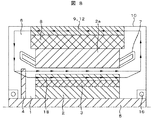
実施例1と同様な効果が得られる構造を図8及び図9に示す。図8及び図9に示すように、回転子鉄心2に周方向に交互に極性を変えて永久磁石3が配置されており、その隣接する異極間となる極間部には、軸方向に伸延し、且つ、極間部から径方向に軸中心へ伸びる溝を設けることで極間通風路18を形成している。
A structure capable of obtaining the same effect as in the first embodiment is shown in FIGS. As shown in FIGS. 8 and 9,
このような構成とすることにより、上述した実施例と同様な効果が得られることは勿論、極間通風路18は永久磁石3と近接して位置するため、極間通風路18による通風冷却により、永久磁石3の発熱を低減することも可能となる。
By adopting such a configuration, it is possible to obtain the same effect as in the above-described embodiment, and since the
尚、本実施例では、回転子1の永久磁石3は平板磁石でV字型配置としているが、その他の磁石形状及び磁石配置としても問題は無い。
In the present embodiment, the
図10は、本発明の第3実施例となる永久磁石式発電機を示すものである。 FIG. 10 shows a permanent magnet generator according to a third embodiment of the present invention.
該図に示す永久磁石式発電機において、回転子1は回転子鉄心2からなり、回転子鉄心2に永久磁石3が埋め込まれており、回転子鉄心2及びアキシャルファン4がシャフト5の両端部に固定されている。また、回転子鉄心2に、軸方向へ通風するためのアキシャルダクト15が周方向に等間隔に複数設けられている。更に、本実施例では、回転子鉄心2の軸方向中心部に、通風冷却用のダクトピース19が周方向に所定間隔をもって径方向に放射状に配置され、このダクトピース19の周方向間で径方向通風路が形成されている。
In the permanent magnet generator shown in the figure, the
一方、固定子6は、固定子鉄心2aが軸方向に積層され固定子コイル7が施されている。固定子6も回転子1と同様に、固定子鉄心2aの軸方向中心部に通風冷却用のダクトピース19が周方向に所定間隔をもって放射状に配置され、このダクトピース19の周方向間で径方向通風路が形成されている。また、固定子6の外周面に接するように、水冷装置8が軸方向中心部に設けられたダクトピース19を境にして2分割して配置され、更に、水冷装置8の外周に通風冷却用のリブ9が周方向に等間隔に配置される。リブ9の外周に発電機フレーム10が固定され、発電機内部は密閉構造となる。
On the other hand, the
このような構成にすることで、上述した実施例と同様な効果が得られることは勿論、シャフト5の両端部に設けられたアキシャルファン4により、回転子鉄心2と固定子鉄心2aとの間及びアキシャルダクト15に導かれた冷却風は、ダクトピース19で形成された径方向通風路を介して発電機内で双方向から循環する複流構造となるため、通風冷却による温度低減効果が期待できる。また、発電機内の最大温度発生部は軸方向中心付近となるため、軸方向中心部に冷却風を流すことで最大温度を低減し発電機内の温度分布を平準化することが可能となる。
By adopting such a configuration, it is possible to obtain the same effect as in the above-described embodiment, and of course, the
尚、本実施例では、ダクトピース19を配置している位置は軸方向中心部であるが、最大温度発生部に合わせてずらした非対称構造にすることで、より効果的に最大温度を低減することが可能となる。また、ダクトピース19を軸方向に所定間隔をもって径方向に放射状に設けても良い。
In this embodiment, the position where the
図11及び図12は、本発明の第4実施例となる永久磁石式発電機を示すものである。 11 and 12 show a permanent magnet generator according to a fourth embodiment of the present invention.
第4実施例では、第1実施例で示した水冷装置8の外周部に設けたリブ9を軸方向中心部を境にし、左右でリブ本数を変えた構成としたものである。即ち、図12に示すように、アキシャルファン4が固定されている側のリブ9の本数より、反対側のリブ9の本数を多くしている。
In the fourth embodiment, the
このように構成することで、上述した実施例と同様な効果が得られることは勿論、リブ9の本数を低減でき、軸方向温度分布に対して温度が上昇する側にリブ9の本数を増やすことで、発電機内の温度分布を平準化することが可能となる。
By configuring in this way, the same effects as in the above-described embodiment can be obtained, and the number of
尚、本実施例ではアキシャルファン4の反対側でリブ9の本数を増やした構成だが、温度分布の高くなる側にリブ9の本数を増やすことが効果的である。
In the present embodiment, the number of
図13は、本発明の第5実施例となる永久磁石式発電機を示すものである。 FIG. 13 shows a permanent magnet generator according to a fifth embodiment of the present invention.
第5実施例では、第1実施例で示した水冷装置8の外周部に設けたリブ9の軸方向長さを、水冷装置8の軸方向長さより短くし軸方向中心部に配置した構成としたものである。
In 5th Example, the axial direction length of the
このように構成することにより、上述した実施例と同様な効果が得られることは勿論、発電機内の最大温度発生部は軸方向中心付近で発生する傾向があるが、第5実施例のように、軸方向中心付近にのみリブ9を設けることで、最大温度を低減し発電機内の温度分布を平準化することが可能となる。
By configuring in this way, the same effect as in the above-described embodiment can be obtained, and the maximum temperature generating part in the generator tends to occur near the center in the axial direction, but as in the fifth embodiment. By providing the
図14は、本発明の第6実施例となる永久磁石式発電機を示すものである。 FIG. 14 shows a permanent magnet generator according to a sixth embodiment of the present invention.
第6実施例では、第1実施例と同様にシャフト5の片側端部に軸方向に冷却風を流すアキシャルファン4を設けているが、回転子2を挟んで反対側端部のシャフト5に径方向に冷却風を流すラジアルファン4aを設けた構成である。
In the sixth embodiment, as in the first embodiment, the
これにより、上述した実施例と同様な効果が得られることは勿論、アキシャルファン4により軸方向に冷却風を流し、更にラジアルファン4aにより径方向に冷却風を流すことで、リブ9間で形成される通風路12に冷却風が流れやすくなり、流量が増加し温度上昇を低減することができる。
As a result, the same effect as that of the above-described embodiment can be obtained, and it is formed between the
図15は、本発明の第7実施例となる永久磁石式発電機を示すものである。 FIG. 15 shows a permanent magnet generator according to a seventh embodiment of the present invention.
第7実施例では、第1実施例で示した固定子コイルのコイルエンド20の長さを左右非対称にした構成である。即ち、図15示すように、アキシャルファン4を設けた側のコイルエンドの20の軸方向長さAより、アキシャルファン4を設けた側とは反対側のコイルエンド20の軸方向長さBを短くしている。
In the seventh embodiment, the length of the
このように構成することにより、上述した実施例と同様な効果が得られることは勿論、アキシャルファン4を設けた側とは反対側のコイルエンド20の軸方向長さBが短いため、軸方向長さが短いコイルエンド20側は、通風抵抗が減少し空気が流れやすくなる。また、コイルエンド20を左右非対称としているため、軸方向の最大温度ピークを温度が低い側にシフトすることが可能となる。
With this configuration, the same effects as those of the above-described embodiment can be obtained, and the axial length B of the
尚、本実施例ではアキシャルファン4の反対側のコイルエンド20を短くしているが、ファンの種類等を変えればアキシャルファン4を固定した側のコイルエンド20を短くしてもよい。
In this embodiment, the
本発明の第8実施例となる第1実施例で示した水冷装置8の内部流路を図16に三次元で示し、図17には、二次元に展開した図を示す。
The internal flow path of the
図16に示す如く、冷却水は流入口21から水冷装置8内に流れ周方向に約1周し、そこから180°流れる向きを変え再び約1周し、それを繰り返して流出口22へと流れる。図18に、水冷装置8の内部で流路を形成するための流路壁23の径方向断面図を示す。流体は周方向に沿って、途中で流れる向きを180°変えながら軸方向へ移動する。流体が流れの向きを変える(Uターンする部分)コーナー部分の流路壁23の端部形状を斜めカット24してある。
As shown in FIG. 16, the cooling water flows from the
このように構成することで、上述した実施例と同様な効果が得られることは勿論、流体が向きを変えるコーナーの外側と内側での流速差で発生する気泡や乱れを緩和し、熱伝達を平準化することができる。また、流路壁23の図示上での下側(発電機を設置したとき地面側になる)に水抜き用の切り欠き25を設けているが、これにより、水冷装置8の地面設置側に排水口を設けることで、水抜き用切り欠き25を介して冷却水が流れ、水冷装置8内の冷却水の溜まりを無くすことができ、メンテナンス性を向上することが可能となる。
By configuring in this way, the same effects as in the above-described embodiment can be obtained, as well as air bubbles and turbulence generated due to the difference in flow velocity between the outside and inside of the corner where the fluid changes direction, and heat transfer is reduced. Can be leveled. Further, a
尚、冷却水を流す装置として、一定速機又は可変速機によるポンプにて水冷装置8に送り込まれる。このとき、可変速機によるポンプを用いた場合、水冷装置8に流す流量も可変できるため、発電機の出力に合わせ流量を調節できるため、ポンプ等の補機類の電力消費を抑え発電機を含めた全体のシステム効率を向上するとことができる。
In addition, it sends to the
図19は、本発明の第9実施例となる第1実施例で示した水冷装置8の流路を二次元に展開した図である。
FIG. 19 is a diagram in which the flow path of the
該図において、冷却水は流入口21から水冷装置8内に流れ、水冷装置8の軸方向の端まで流れ、そこから180°流れる向きを変えて、それを繰り返しながら周方向に移動し流出口22へと流れる。
In this figure, the cooling water flows from the
このような構成にすることで、軸方向に冷却水がUターンしながら流れるため、軸方向の温度分布は平準化しやすくなる。また流路壁23aは実施例8で示した流路壁23とは異なるバー形状となるため加工性が良く、冷却水の向きを変える(Uターンする部分)コーナー部分の流路壁23aの端部形状を斜めカット24にすることで、実施例8に示した構成と同様の効果が得られる。
With such a configuration, the cooling water flows while making a U-turn in the axial direction, so that the axial temperature distribution is easily leveled. Further, since the
図20は、本発明の第10実施例となる永久磁石式発電機を示すものである。 FIG. 20 shows a permanent magnet generator according to a tenth embodiment of the present invention.
第10実施例では、第1実施例で示した水冷装置8の内部に、通風冷却用のパイプ26を設けている。図21にパイプ26を設けた水冷装置8の平面展開図を示す。同図で示すように、通風冷却用のパイプ26は水冷装置8の内部に軸方向へ貫通するよう配置してある。
In the tenth embodiment, a
このような構成にすることで、上述した実施例と同様な効果が得られることは勿論、リブ9を通過する冷却風と水冷装置8にも冷却風が流れ、水冷による冷却とパイプ26を介した熱交換作用により、より冷却効率が向上する。尚、実施例10の構成を実施例3で示した構成にすることも可能である。
By adopting such a configuration, the same effects as in the above-described embodiment can be obtained, and the cooling air also flows through the cooling air passing through the
図22は、本発明の第11実施例となる永久磁石式発電機を示すものである。 FIG. 22 shows a permanent magnet generator according to an eleventh embodiment of the present invention.
今までの各実施例では、水冷装置8の外周側の周方向に等間隔にリブ9を設け、このリブ9間で冷却風が通る通風路12を形成していたが、図22に示す第11実施例では、リブ9を排除し、水冷装置8に直接冷却風が通るパイプ26を設けた構成にしても良い。
In each of the embodiments so far, the
このように構成することで、機内を冷却して温まった冷却風はパイプ26に導かれ、ここで水冷装置8との熱交換が行われ、温まった冷却風が冷却され、冷却された冷却風が、アキシャルファン4により、再度発電機内を循環されることになり、上述した第1実施例と同様な効果を得ることができる。また、リブ9が無くなるので部品点数を低減でき、生産性を向上することができる。
With this configuration, the cooling air warmed by cooling the inside of the machine is guided to the
図23は、本発明の発電機を風力発電システムに適用した例を示す。 FIG. 23 shows an example in which the generator of the present invention is applied to a wind power generation system.
第1実施例から第11実施例で示した発電機100は、風車101と増速ギア102を介して接続され、風車ナセル103内に設置される。更に発電機100は、電力系統104と電力変換器105を介して接続され、発電運転を行うことができる。また、風車101と発電機100は、直結することも可能である。
The
尚、本実施例では、風力を動力源としているが、例えば水車,エンジン,タービンなどでも十分適用が可能である。 In this embodiment, wind power is used as a power source, but it can be sufficiently applied to, for example, a water turbine, an engine, a turbine, and the like.
上記実施例の風力発電用発電機は、大容量となった場合に、小型で冷却が行える利点がある。 The wind power generator of the above embodiment has an advantage that it can be cooled in a small size when it has a large capacity.
1 回転子
2 回転子鉄心
2a 固定子鉄心
3 永久磁石
4 アキシャルファン
4a ラジアルファン
5 シャフト
6 固定子
7 固定子コイル
8 水冷装置
9 リブ
10 発電機フレーム
11 固定子スロット
12 通風路
15 アキシャルダクト
16 軸受
17 プレート
18 極間通風路
19 ダクトピース
20 コイルエンド
21 流入口
22 流出口
23,23a 流路壁
24 斜めカット
25 切り欠き
26 パイプ
100 発電機
101 風車
102 増速ギア
103 風車ナセル
104 電力系統
105 電力変換器
DESCRIPTION OF
Claims (15)
前記水冷装置は複数のリブを有し、前記水冷装置の外周には前記リブが周方向に所定間隔をもって複数配置されると共に、該リブの外周側に回転電機全体を覆うフレームが配置され、前記水冷装置の外周側とリブ間及び前記フレーム間で囲まれた前記冷却風が通る通風路が形成され、かつ、前記ファンにより機内を循環させて冷却した冷却風を前記通風路に導き、該通風路内を通る冷却風と前記水冷装置とで熱交換した冷却風を再度前記機内に循環させ、
前記水冷装置の内部流路を形成する流路壁は、冷却媒体が周方向に沿って流れ、かつ途中で流れる向きを変えながら軸方向に移動するように、流路を形成し、前記流路において前記冷却媒体が流れる向きが変わるコーナー部の流路壁端部形状を斜め形状にしたことを特徴とする永久磁石式回転電機。 A stator in which a stator coil is applied to the stator core, and a plurality of permanent magnets arranged in the circumferential direction on the rotor core that is disposed opposite to the stator core of the stator with a predetermined gap and fixed to the shaft. A rotor, a water cooling device disposed on the outer peripheral side of the stator core, and a fan that is fixed to a shaft on at least one side of the axial end of the rotor core and circulates cooling air in the machine. In the provided permanent magnet type rotating electrical machine,
The water cooling device has a plurality of ribs, and a plurality of ribs are arranged at predetermined intervals in the circumferential direction on the outer periphery of the water cooling device, and a frame that covers the entire rotating electrical machine is arranged on the outer periphery side of the ribs, A ventilation path through which the cooling air surrounded between the outer peripheral side of the water cooling device and the ribs and between the frames is formed, and the cooling air cooled by circulating in the apparatus by the fan is guided to the ventilation path, Circulating the cooling air that has exchanged heat between the cooling air passing through the road and the water cooling device, again in the machine ,
The flow path wall forming the internal flow path of the water cooling device forms the flow path so that the cooling medium flows along the circumferential direction and moves in the axial direction while changing the direction of flowing in the middle. A permanent magnet type rotating electrical machine characterized in that the shape of the flow path wall end portion of the corner portion in which the flow direction of the cooling medium changes is an oblique shape .
前記回転子鉄心に、軸方向に前記冷却風を通すためのアキシャルダクトが周方向に所定間隔をもって複数設けられていることを特徴とする永久磁石式回転電機。 In the permanent magnet type rotating electrical machine according to claim 1,
A permanent magnet type rotating electrical machine, wherein a plurality of axial ducts for passing the cooling air in the axial direction are provided in the circumferential direction in the rotor core.
前記回転子鉄心とシャフトの間に、軸方向に延びたプレートが周方向に所定間隔をもって複数配置され、該周方向に複数配置された前記プレート間で軸方向に前記冷却風を通すためのアキシャルダクトが形成されていることを特徴とする永久磁石式回転電機。 In the permanent magnet type rotating electrical machine according to claim 1,
Between the rotor core and the shaft, a plurality of plates extending in the axial direction are arranged at predetermined intervals in the circumferential direction, and an axial for passing the cooling air in the axial direction between the plurality of plates arranged in the circumferential direction. A permanent magnet type rotating electrical machine, characterized in that a duct is formed.
前記永久磁石は、前記回転子鉄心に周方向に交互に極性を変えて配置されると共に、該永久磁石の隣接する異極間となる極間部には、軸方向に延伸し、かつ、極間部から径方向に延びて前記冷却風を通すための通風路が設けられていることを特徴とする永久磁石式回転電機。 In the permanent magnet type rotating electrical machine according to claim 1,
The permanent magnets are arranged on the rotor core with alternating polarities in the circumferential direction. The permanent magnets extend in the axial direction between the adjacent different poles of the permanent magnets. A permanent magnet type rotating electrical machine characterized in that a ventilation passage is provided extending in a radial direction from the space for passing the cooling air.
前記水冷装置の外周に周方向に所定間隔をもって複数配置された前記リブは、その本数が軸方向中心部を境に変わっていることを特徴とする永久磁石式回転電機。 In the permanent magnet type rotating electrical machine according to claim 1,
A permanent magnet type rotating electrical machine characterized in that a plurality of the ribs arranged at predetermined intervals in the circumferential direction on the outer periphery of the water cooling device are changed with the central portion in the axial direction as a boundary.
前記リブの本数は、軸方向中心部を境に前記ファンが設置されている側が少ないことを特徴とする永久磁石式回転電機。 In the permanent magnet type rotating electrical machine according to claim 5,
The number of the ribs is small on the side where the fan is installed with respect to the central portion in the axial direction.
前記水冷装置の外周に周方向に所定間隔をもって複数配置された前記リブは、その軸方向長さが前記水冷装置の軸方向長さより短く、かつ、軸方向中心部に配置されていることを特徴とする永久磁石式回転電機。 In the permanent magnet type rotating electrical machine according to claim 1,
A plurality of the ribs arranged on the outer periphery of the water cooling device at a predetermined interval in the circumferential direction have an axial length shorter than an axial length of the water cooling device, and are arranged at a central portion in the axial direction. Permanent magnet type rotating electrical machine.
冷却風を機内に循環させるファンとして、軸方向に冷却風を流すアキシャルファンと、該アキシャルファンとは回転子を挟んで反対側の前記シャフトに設けられ、径方向に冷却風を流すラジアルファンとを用いたことを特徴とする永久磁石式回転電機。 In the permanent magnet type rotating electrical machine according to claim 1,
An axial fan that flows cooling air in the axial direction as a fan that circulates cooling air into the machine, and a radial fan that is provided on the shaft on the opposite side of the axial fan and that passes cooling air, Permanent magnet type rotating electrical machine characterized by using
前記固定子コイルのエンド部の軸方向長さを左右非対称にしたことを特徴とする永久磁石式回転電機。 In the permanent magnet type rotating electrical machine according to claim 2,
A permanent magnet type rotating electrical machine characterized in that the axial length of the end portion of the stator coil is asymmetric.
前記水冷装置は、その内部に軸方向を貫通する冷却風が通る複数のパイプが設けられていることを特徴とする永久磁石式回転電機。 In the permanent magnet type rotating electrical machine according to claim 1,
The water-cooling device is provided with a plurality of pipes through which cooling air penetrating in the axial direction passes.
前記ファンは、前記回転子鉄心の軸方向両端部のシャフトに固定され、
前記固定子及び回転子の少なくとも軸方向中心部にダクトピースが周方向に所定間隔をもって径方向に放射状に延びて配置され、該ダクトピースの周方向間で径方向通風路が形成され、かつ、前記水冷装置は、その少なくとも軸方向中心部に設けられた前記ダクトピースを境にして分割されると共に、前記回転子鉄心の軸方向両端部のシャフトに固定されたそれぞれのファンにより、前記通風路を通った冷却風を機内に双方向から循環させて前記径方向通風路に導き、該径方向通風路から前記通風路に導かれた冷却風と前記水冷装置とで熱交換された冷却風を再度前記機内に双方向から循環させることを特徴とする永久磁石式回転電機。 In the permanent magnet type rotating electrical machine according to claim 1,
The fan is fixed to shafts at both axial ends of the rotor core,
A duct piece is arranged radially extending at a predetermined interval in the circumferential direction at least in the axial center of the stator and the rotor, and a radial ventilation path is formed between the circumferential directions of the duct piece; and The water cooling device is divided at least at the duct piece provided at the axially central portion of the water cooling device, and the ventilation path is provided by respective fans fixed to shafts at both axial end portions of the rotor core. The cooling air that has passed through is circulated in both directions in the machine and guided to the radial ventilation path, and the cooling air that is heat-exchanged between the cooling air guided from the radial ventilation path to the ventilation path and the water cooling device is A permanent magnet type rotating electrical machine that is circulated again in both directions in the machine.
前記回転子鉄心に、軸方向に前記冷却風を通すためのアキシャルダクトが周方向に所定間隔をもって複数設けられていることを特徴とする永久磁石式回転電機。 In the permanent magnet type rotating electrical machine according to claim 11,
A permanent magnet type rotating electrical machine, wherein a plurality of axial ducts for passing the cooling air in the axial direction are provided in the circumferential direction in the rotor core.
前記水冷装置の内部流路を形成する流路壁は、回転電機を設置した地面側の位置する方向に水抜き用の切り欠きが設けられていることを特徴とする永久磁石式回転電機。A permanent magnet type rotating electrical machine characterized in that a flow path wall forming an internal flow path of the water cooling device is provided with a notch for draining in a direction on the ground side where the rotating electrical machine is installed.
前記水冷装置の外周には冷却風が通る複数のパイプが配置され、かつ、前記ファンにより機内を循環させて冷却した冷却風を前記パイプに導き、該パイプ内を通る冷却風と前記水冷装置とで熱交換した冷却風を再度前記機内に循環させることを特徴とする永久磁石式回転電機。A plurality of pipes through which cooling air passes are arranged on the outer periphery of the water cooling device, and the cooling air cooled by circulating in the apparatus by the fan is guided to the pipe, and the cooling air passing through the pipe, the water cooling device, A permanent magnet type rotating electrical machine characterized by circulating the cooling air heat-exchanged in the machine again in the machine.
前記回転電機は、請求項1乃至14のいずれか1項に記載の永久磁石式回転電機であることを特徴とする風力発電システム。The wind power generation system, wherein the rotating electrical machine is the permanent magnet type rotating electrical machine according to any one of claims 1 to 14.
Priority Applications (4)
| Application Number | Priority Date | Filing Date | Title |
|---|---|---|---|
| JP2010076566A JP5260591B2 (en) | 2010-03-30 | 2010-03-30 | Permanent magnet rotating electrical machine and wind power generation system |
| EP11000915.6A EP2372881A3 (en) | 2010-03-30 | 2011-02-04 | Permanent magnetic rotating electric machine and wind power generating system |
| CN2011100409861A CN102208845A (en) | 2010-03-30 | 2011-02-17 | Permanent magnetic rotating electric machine and wind power generating system |
| US13/029,287 US8653703B2 (en) | 2010-03-30 | 2011-02-17 | Permanent magnetic rotating electric machine and wind power generating system |
Applications Claiming Priority (1)
| Application Number | Priority Date | Filing Date | Title |
|---|---|---|---|
| JP2010076566A JP5260591B2 (en) | 2010-03-30 | 2010-03-30 | Permanent magnet rotating electrical machine and wind power generation system |
Publications (2)
| Publication Number | Publication Date |
|---|---|
| JP2011211816A JP2011211816A (en) | 2011-10-20 |
| JP5260591B2 true JP5260591B2 (en) | 2013-08-14 |
Family
ID=44310888
Family Applications (1)
| Application Number | Title | Priority Date | Filing Date |
|---|---|---|---|
| JP2010076566A Active JP5260591B2 (en) | 2010-03-30 | 2010-03-30 | Permanent magnet rotating electrical machine and wind power generation system |
Country Status (4)
| Country | Link |
|---|---|
| US (1) | US8653703B2 (en) |
| EP (1) | EP2372881A3 (en) |
| JP (1) | JP5260591B2 (en) |
| CN (1) | CN102208845A (en) |
Families Citing this family (47)
| Publication number | Priority date | Publication date | Assignee | Title |
|---|---|---|---|---|
| GB2485184B (en) * | 2010-11-04 | 2013-12-11 | Evo Electric Ltd | Axial flux electrical machines |
| ES2787607T3 (en) * | 2010-11-04 | 2020-10-16 | Wobben Properties Gmbh | Wind power plant with synchronous generator and slow-turning synchronous generator |
| US8847444B2 (en) | 2010-11-12 | 2014-09-30 | Hamilton Sundstrand Space Systems International, Inc. | Cooling of permanent magnet electric machine |
| AT510446B1 (en) * | 2010-11-18 | 2012-04-15 | Avl List Gmbh | ELECTRICAL MACHINE |
| FI123660B (en) * | 2010-12-15 | 2013-08-30 | Switch Drive Systems Oy | Cooling system for an electric machine |
| EP2602916A1 (en) * | 2011-12-06 | 2013-06-12 | Hamilton Sundstrand Space Systems International, Inc. | Cooling of permanent magnet electric machine |
| CN103187829A (en) * | 2011-12-30 | 2013-07-03 | 哈米尔顿森德斯特兰德空间系统国际有限公司 | Cooling of permanent magnet motor |
| CN102570670B (en) * | 2012-01-17 | 2014-06-04 | 东元总合科技(杭州)有限公司 | Rotor with internal spacers and motor employing rotor |
| CN102611248B (en) * | 2012-03-16 | 2013-12-04 | 赵晓东 | Permanent magnet synchronous motor cooled by two stages of heat exchangers |
| WO2013171839A1 (en) * | 2012-05-15 | 2013-11-21 | 株式会社安川電機 | Dynamo-electric machine |
| DE102012208549A1 (en) * | 2012-05-22 | 2013-11-28 | Wobben Properties Gmbh | Optimized synchronous generator of a gearless wind turbine |
| GB2506970B (en) * | 2012-08-24 | 2020-12-30 | Borgwarner Inc | A shield and coolant guide for an electric machine |
| US20140084721A1 (en) * | 2012-09-25 | 2014-03-27 | Debabrata Pal | Motor assembly cooling arrangement and method of cooling a motor assembly |
| JP5547783B2 (en) * | 2012-09-27 | 2014-07-16 | 株式会社小松製作所 | Electric motor and its cooling water circuit |
| US9058955B2 (en) | 2012-12-06 | 2015-06-16 | GE Lighting Solutions, LLC | Lamp comprising active cooling device for thermal management |
| JP6063288B2 (en) * | 2013-02-15 | 2017-01-18 | 住友重機械工業株式会社 | Power transmission device |
| CN104079119A (en) * | 2013-03-26 | 2014-10-01 | 德昌电机(深圳)有限公司 | Motor assembly and household appliance comprising motor assembly |
| NO335892B1 (en) * | 2013-04-10 | 2015-03-16 | Smartmotor As | Underwater electromechanical energy converter |
| JP2014220901A (en) * | 2013-05-08 | 2014-11-20 | 三菱電機株式会社 | Permanent magnet built-in type rotary electric machine |
| JP6169496B2 (en) * | 2014-01-09 | 2017-07-26 | 株式会社日立製作所 | Permanent magnet rotating electric machine |
| DE102015006348A1 (en) * | 2014-05-20 | 2015-11-26 | Schaeffler Technologies AG & Co. KG | Space-optimized cooling jacket with holder-holding separating web for an electrical machine |
| CN104167841A (en) * | 2014-08-26 | 2014-11-26 | 冯军 | Electric generator |
| DE102014220847A1 (en) * | 2014-10-15 | 2016-04-21 | Würth Elektronik eiSos Gmbh & Co. KG | communicator |
| EP3046225A1 (en) * | 2015-01-16 | 2016-07-20 | Siemens Aktiengesellschaft | Electric rotary machine having one-sided cooling, and method for one-sided cooling |
| CN104810997B (en) * | 2015-04-15 | 2017-03-01 | 新疆金风科技股份有限公司 | Permanent magnet direct-driving aerogenerator system and its collaborative drying control method of sealing |
| CN104953766B (en) * | 2015-06-17 | 2018-11-13 | 北京金风科创风电设备有限公司 | Radial ventilation cooling structure of motor |
| EP3142231A1 (en) * | 2015-09-08 | 2017-03-15 | ABB Technology AG | An electric power generator |
| CN105245046A (en) * | 2015-10-26 | 2016-01-13 | 王石柱 | High speed motor rotor structure and processing technology |
| JP2017192163A (en) * | 2016-04-11 | 2017-10-19 | 東芝三菱電機産業システム株式会社 | Totally-enclosed dynamo-electric machine |
| JP2020513722A (en) | 2016-11-29 | 2020-05-14 | ティーエム4・インコーポレーテッド | Electric machine with enclosed cooling assembly combined with open cooling assembly |
| DE102017107897A1 (en) | 2017-04-12 | 2018-10-18 | Wobben Properties Gmbh | Method for cooling a gearless wind turbine |
| CN106849509B (en) * | 2017-04-25 | 2023-06-06 | 沈阳工程学院 | Hollow rotor cooling structure of ultra-high-speed permanent magnet motor |
| CN109301973B (en) * | 2017-07-24 | 2021-07-30 | 西门子公司 | Motor and ship propulsion device |
| CN107370292A (en) * | 2017-07-31 | 2017-11-21 | 中车唐山机车车辆有限公司 | The cooling device of magneto |
| JP7269663B2 (en) * | 2017-10-10 | 2023-05-09 | ゼロ イー テクノロジーズ,エルエルシー | Electric machine cooling and stabilization system and method |
| TWI652884B (en) * | 2017-12-20 | 2019-03-01 | 東元電機股份有限公司 | Motor frame with bumps |
| JP6624223B2 (en) | 2018-03-09 | 2019-12-25 | 株式会社明電舎 | Rotating electric machine |
| CN112470367A (en) * | 2018-06-07 | 2021-03-09 | 马威动力控制技术有限公司 | Rotor for an electric machine comprising an air-cooling element and electric machine comprising said rotor |
| CN111490635A (en) * | 2019-01-29 | 2020-08-04 | 青岛海尔智能技术研发有限公司 | Motor cooling system of centrifugal refrigeration compressor and centrifugal refrigeration compressor |
| JP2020129891A (en) * | 2019-02-08 | 2020-08-27 | 株式会社日立インダストリアルプロダクツ | Rotary electric machine and hoist system using the same for elevator |
| CN112421885A (en) * | 2020-11-10 | 2021-02-26 | 国家电网有限公司 | Closed-circuit self-circulation ventilation cooling system of hydraulic generator |
| CN112636501B (en) * | 2020-11-27 | 2022-04-08 | 联合汽车电子有限公司 | Motor rotor and motor |
| CN112803635B (en) * | 2021-03-22 | 2021-06-29 | 沈阳工业大学 | Cooling system structure of permanent magnet motor |
| EP4064555A1 (en) | 2021-03-25 | 2022-09-28 | Wobben Properties GmbH | Wind turbine and method for controlling a wind turbine |
| US11863051B2 (en) | 2021-05-13 | 2024-01-02 | General Electric Company | Thermal management system |
| US11942826B2 (en) * | 2021-09-24 | 2024-03-26 | Rolls-Royce Electrical Norway AS | Electric machine cooling |
| CN114320771B (en) * | 2021-12-02 | 2023-07-07 | 江苏海迪威液压有限公司 | Wind turbine generator system converter water cooling system cooling state assessment early warning device |
Family Cites Families (24)
| Publication number | Priority date | Publication date | Assignee | Title |
|---|---|---|---|---|
| US2505795A (en) * | 1946-11-13 | 1950-05-02 | Ohio Crankshaft Co | Cooling power unit |
| DE1802282U (en) * | 1958-10-01 | 1959-12-17 | Licentia Gmbh | COOLING ARRANGEMENT FOR CLOSED ELECTRIC MACHINERY WITH COOLED STAND HOUSING. |
| DE1763579A1 (en) * | 1968-06-26 | 1971-11-11 | Siemens Ag | Arrangement for liquid cooling of the stator core assemblies of electrical machines, especially for turbo generators |
| US3784851A (en) * | 1971-03-03 | 1974-01-08 | Fuji Electric Co Ltd | Ventillating arrangement for dynamo-electric machines |
| JPS57202855A (en) * | 1982-05-13 | 1982-12-11 | Toshiba Corp | Air cooler for rotary electric machine |
| IT209469Z2 (en) * | 1985-07-09 | 1988-10-10 | Lafert Srl | FORCED ELECTRIC MOTOR FORCED WITH LIQUID. |
| JPH09149599A (en) | 1995-11-27 | 1997-06-06 | Hitachi Ltd | Totally enclosed rotating electric machine |
| JPH09285071A (en) | 1996-04-19 | 1997-10-31 | Fuji Electric Co Ltd | Coolant-cooled dynamo-electric machine |
| CN2271771Y (en) * | 1996-07-02 | 1997-12-31 | 施振山 | Hull of electric machine with flow guiding radiating path |
| JP3205897B2 (en) * | 1996-07-12 | 2001-09-04 | 株式会社滋賀山下 | Hammering equipment for casting sand removal |
| JPH10290551A (en) * | 1997-04-15 | 1998-10-27 | Matsushita Electric Works Ltd | Motor |
| JP2000116060A (en) * | 1998-09-29 | 2000-04-21 | Nishishiba Electric Co Ltd | Rotating electric machine |
| DE19905540A1 (en) * | 1999-02-10 | 2000-08-17 | Zahnradfabrik Friedrichshafen | Electrical machine |
| JP2001238395A (en) * | 2000-02-25 | 2001-08-31 | Hitachi Ltd | Fully enclosed motor fitted with cooling rib |
| US6737768B2 (en) * | 2000-03-31 | 2004-05-18 | Hitachi, Ltd. | Rotating electric machine |
| US7019413B2 (en) * | 2000-05-19 | 2006-03-28 | Yukio Kinoshita | System having an electric device which functions both as an electric motor for driving machines and as a generator to generate electrical power, and having a power source for driving the electric device |
| JP2005039926A (en) * | 2003-07-14 | 2005-02-10 | Kawasaki Heavy Ind Ltd | Low-speed motor |
| JP4572647B2 (en) | 2004-10-01 | 2010-11-04 | 株式会社日立製作所 | Permanent magnet rotating electrical machine and wind power generation system |
| JP2006197785A (en) * | 2004-12-14 | 2006-07-27 | Nissan Motor Co Ltd | Cooling device of motor |
| JP4800847B2 (en) * | 2006-06-01 | 2011-10-26 | 三菱電機株式会社 | Fully closed liquid-cooled electric motor |
| DE102006043169B4 (en) * | 2006-09-14 | 2008-10-16 | Siemens Ag | Electric machine with an internally cooled rotor |
| JP5157138B2 (en) * | 2006-11-24 | 2013-03-06 | 株式会社日立製作所 | Permanent magnet rotating electrical machine and wind power generation system |
| JP2009038864A (en) | 2007-07-31 | 2009-02-19 | Nissan Motor Co Ltd | Cooler for motor and cooling method thereof |
| CN201142605Y (en) * | 2008-01-15 | 2008-10-29 | 江苏远东电机制造有限公司 | Ventilation structure between motor seat and stator |
-
2010
- 2010-03-30 JP JP2010076566A patent/JP5260591B2/en active Active
-
2011
- 2011-02-04 EP EP11000915.6A patent/EP2372881A3/en not_active Withdrawn
- 2011-02-17 US US13/029,287 patent/US8653703B2/en not_active Expired - Fee Related
- 2011-02-17 CN CN2011100409861A patent/CN102208845A/en active Pending
Also Published As
| Publication number | Publication date |
|---|---|
| EP2372881A3 (en) | 2017-04-12 |
| JP2011211816A (en) | 2011-10-20 |
| EP2372881A2 (en) | 2011-10-05 |
| US8653703B2 (en) | 2014-02-18 |
| US20110241350A1 (en) | 2011-10-06 |
| CN102208845A (en) | 2011-10-05 |
Similar Documents
| Publication | Publication Date | Title |
|---|---|---|
| JP5260591B2 (en) | Permanent magnet rotating electrical machine and wind power generation system | |
| JP5358667B2 (en) | Permanent magnet generator | |
| US7994668B2 (en) | Cooling system for rotating machine | |
| CA2656986C (en) | Process and devices for cooling an electric machine | |
| CN102598479B (en) | Wind power generator having an internal coolant circuit | |
| JP4572647B2 (en) | Permanent magnet rotating electrical machine and wind power generation system | |
| US8350434B2 (en) | Permanent magnet type rotary electric machine | |
| JP2015208101A (en) | Squirrel-cage motor | |
| JP2008131813A (en) | Permanent magnet electrical rotating machine, wind power generation system, and magnetization method of permanent magnet | |
| JP2013179746A (en) | Rotary electric machine and electric vehicle | |
| JP2014033584A (en) | Wind cooling structure of rotary electric machine | |
| US20140175919A1 (en) | Rotating electrical machine and housing for rotating electrical machine | |
| JP5388961B2 (en) | Rotating electric machine | |
| JP2015208103A (en) | Squirrel-cage motor | |
| CA2756448A1 (en) | Brushless lundell-type alternator with liquid cooling channels | |
| JP2022019594A (en) | Cooling of electrical machines | |
| CN112383191A (en) | Self-fan cold axial flux motor with external centrifugal fan | |
| CN108448818A (en) | A kind of brushless dual-feed motor cooling structure based on coolant liquid | |
| JP2012100458A (en) | Cooling structure for generator | |
| JP2011254579A (en) | Rotary electric machine | |
| JP2013158161A (en) | Rotary electric machine | |
| JP6602619B2 (en) | Rotating electric machine or wind power generation system | |
| JP2012095534A (en) | Permanent magnet-type rotary electric machine | |
| CN208797768U (en) | A kind of brushless dual-feed motor cooling structure based on coolant liquid | |
| JP6325339B2 (en) | Rotating electrical machine system and wind power generation system |
Legal Events
| Date | Code | Title | Description |
|---|---|---|---|
| A621 | Written request for application examination |
Free format text: JAPANESE INTERMEDIATE CODE: A621 Effective date: 20111125 |
|
| A977 | Report on retrieval |
Free format text: JAPANESE INTERMEDIATE CODE: A971007 Effective date: 20120404 |
|
| A131 | Notification of reasons for refusal |
Free format text: JAPANESE INTERMEDIATE CODE: A131 Effective date: 20120410 |
|
| A521 | Written amendment |
Free format text: JAPANESE INTERMEDIATE CODE: A523 Effective date: 20120608 |
|
| A131 | Notification of reasons for refusal |
Free format text: JAPANESE INTERMEDIATE CODE: A131 Effective date: 20121009 |
|
| A521 | Written amendment |
Free format text: JAPANESE INTERMEDIATE CODE: A523 Effective date: 20121210 |
|
| TRDD | Decision of grant or rejection written | ||
| A01 | Written decision to grant a patent or to grant a registration (utility model) |
Free format text: JAPANESE INTERMEDIATE CODE: A01 Effective date: 20130402 |
|
| A61 | First payment of annual fees (during grant procedure) |
Free format text: JAPANESE INTERMEDIATE CODE: A61 Effective date: 20130425 |
|
| FPAY | Renewal fee payment (event date is renewal date of database) |
Free format text: PAYMENT UNTIL: 20160502 Year of fee payment: 3 |
|
| R151 | Written notification of patent or utility model registration |
Ref document number: 5260591 Country of ref document: JP Free format text: JAPANESE INTERMEDIATE CODE: R151 |
|
| S111 | Request for change of ownership or part of ownership |
Free format text: JAPANESE INTERMEDIATE CODE: R313111 |
|
| R350 | Written notification of registration of transfer |
Free format text: JAPANESE INTERMEDIATE CODE: R350 |