JP6624223B2 - Rotating electric machine - Google Patents
Rotating electric machine Download PDFInfo
- Publication number
- JP6624223B2 JP6624223B2 JP2018042614A JP2018042614A JP6624223B2 JP 6624223 B2 JP6624223 B2 JP 6624223B2 JP 2018042614 A JP2018042614 A JP 2018042614A JP 2018042614 A JP2018042614 A JP 2018042614A JP 6624223 B2 JP6624223 B2 JP 6624223B2
- Authority
- JP
- Japan
- Prior art keywords
- stator
- frame
- electric machine
- cooling water
- rotating electric
- Prior art date
- Legal status (The legal status is an assumption and is not a legal conclusion. Google has not performed a legal analysis and makes no representation as to the accuracy of the status listed.)
- Active
Links
Images


Classifications
-
- H—ELECTRICITY
- H02—GENERATION; CONVERSION OR DISTRIBUTION OF ELECTRIC POWER
- H02K—DYNAMO-ELECTRIC MACHINES
- H02K9/00—Arrangements for cooling or ventilating
- H02K9/02—Arrangements for cooling or ventilating by ambient air flowing through the machine
-
- H—ELECTRICITY
- H02—GENERATION; CONVERSION OR DISTRIBUTION OF ELECTRIC POWER
- H02K—DYNAMO-ELECTRIC MACHINES
- H02K1/00—Details of the magnetic circuit
- H02K1/06—Details of the magnetic circuit characterised by the shape, form or construction
- H02K1/12—Stationary parts of the magnetic circuit
- H02K1/20—Stationary parts of the magnetic circuit with channels or ducts for flow of cooling medium
-
- H—ELECTRICITY
- H02—GENERATION; CONVERSION OR DISTRIBUTION OF ELECTRIC POWER
- H02K—DYNAMO-ELECTRIC MACHINES
- H02K5/00—Casings; Enclosures; Supports
- H02K5/04—Casings or enclosures characterised by the shape, form or construction thereof
- H02K5/12—Casings or enclosures characterised by the shape, form or construction thereof specially adapted for operating in liquid or gas
-
- H—ELECTRICITY
- H02—GENERATION; CONVERSION OR DISTRIBUTION OF ELECTRIC POWER
- H02K—DYNAMO-ELECTRIC MACHINES
- H02K5/00—Casings; Enclosures; Supports
- H02K5/04—Casings or enclosures characterised by the shape, form or construction thereof
- H02K5/20—Casings or enclosures characterised by the shape, form or construction thereof with channels or ducts for flow of cooling medium
- H02K5/203—Casings or enclosures characterised by the shape, form or construction thereof with channels or ducts for flow of cooling medium specially adapted for liquids, e.g. cooling jackets
-
- H—ELECTRICITY
- H02—GENERATION; CONVERSION OR DISTRIBUTION OF ELECTRIC POWER
- H02K—DYNAMO-ELECTRIC MACHINES
- H02K5/00—Casings; Enclosures; Supports
- H02K5/04—Casings or enclosures characterised by the shape, form or construction thereof
- H02K5/20—Casings or enclosures characterised by the shape, form or construction thereof with channels or ducts for flow of cooling medium
- H02K5/207—Casings or enclosures characterised by the shape, form or construction thereof with channels or ducts for flow of cooling medium with openings in the casing specially adapted for ambient air
-
- H—ELECTRICITY
- H02—GENERATION; CONVERSION OR DISTRIBUTION OF ELECTRIC POWER
- H02K—DYNAMO-ELECTRIC MACHINES
- H02K9/00—Arrangements for cooling or ventilating
- H02K9/02—Arrangements for cooling or ventilating by ambient air flowing through the machine
- H02K9/04—Arrangements for cooling or ventilating by ambient air flowing through the machine having means for generating a flow of cooling medium
Landscapes
- Engineering & Computer Science (AREA)
- Power Engineering (AREA)
- Motor Or Generator Cooling System (AREA)
Description
本発明は、発電機や電動機等の回転電機に関する。 The present invention relates to a rotating electric machine such as a generator or a motor.
高出力化や高速回転化等を要求される大型の発電機や電動機等の回転電機においては、高出力化に対応して、固定子の内部やコイルエンド等の巻線部分に厚手の高圧絶縁紙が使用されると共に、高速回転化に対応して、回転子の磁石が回転軸にリングで覆われるように固定されることから、固定子の巻線部分や回転子の磁石部分が放熱しにくくなり、温度上昇しやすくなっている。 In rotating electric machines such as large generators and electric motors that require high output and high-speed rotation, thick high-voltage insulation is applied to the inside of the stator and windings such as coil ends in response to the increase in output. Since paper is used and the rotor magnet is fixed so that it is covered with a ring on the rotating shaft in response to high-speed rotation, the stator windings and the rotor magnet dissipate heat. It becomes difficult and the temperature rises easily.
そのため、例えば、下記特許文献1においては、フレームと固定子との間に水冷ジャケットを設けると共に、水冷ジャケットとフレームとの間に通風路を形成し、水冷ジャケットに冷却水を流通させると共に、フレーム内の空気を上記通風路に流通させるように循環させることにより、固定子や回転子を冷却することを提案している。
Therefore, for example, in
上述したような大型の回転電機においては、更なる高出力化や高速回転化等の要求に伴って、冷却性能の更なる向上が強く求められている。 In the large rotating electric machines as described above, further improvement in cooling performance is strongly demanded in accordance with demands for higher output and higher speed rotation.
前述した課題を解決するための、本発明に係る回転電機は、円筒形をなすフレームと、前記フレームの内部に取り付けられた円筒形をなす固定子と、前記固定子との間にギャップを有するように当該固定子の内部に配設された円筒形をなす回転子と、前記回転子の内部を貫通するように当該回転子に取り付けられた回転軸と、前記フレームに取り付けられて前記回転軸を回転可能に支持するブラケットとを備えている回転電機において、前記固定子が、軸方向中央部分に径方向へ沿って形成されて前記ギャップに連通するダクトを有し、前記フレームが、冷却風を軸方向両端寄りの内部に供給する第一の供給口及び内部の冷却風を外部へ排出する排出口をそれぞれ有すると共に、冷却風を前記固定子の前記ダクトへ供給する第二の供給口を有していることを特徴とする。 In order to solve the above-described problem, a rotating electric machine according to the present invention has a cylindrical frame, a cylindrical stator mounted inside the frame, and a gap between the stator. A cylindrical rotor disposed inside the stator, a rotary shaft attached to the rotor so as to penetrate the interior of the rotor, and the rotary shaft mounted to the frame. And a bracket rotatably supporting the stator, the stator has a duct formed radially at a central portion in the axial direction and communicating with the gap, and the frame is provided with a cooling wind. A first supply port for supplying the cooling air to the interior of the stator, and a second supply port for supplying the cooling air to the duct of the stator. Yes And wherein the are.
また、本発明に係る回転電機は、上述した回転電機において、前記フレームの軸方向中程の一方端寄りと他方端寄りとに対をなすように配設されて冷却水を供給される供給口を軸方向中央寄りに有すると共に冷却水を排出する排出口を軸方向端部寄りに有する冷却水管を備えていることを特徴とする。 Further, the rotating electric machine according to the present invention is the above-described rotating electric machine, wherein the supply port is provided so as to form a pair near one end and near the other end in the axial middle of the frame and is supplied with cooling water. And a cooling water pipe having a discharge port for discharging the cooling water near the axial end.
また、本発明に係る回転電機は、上述した回転電機において、前記フレームが、前記冷却水管を外周面と内周面との間に内装するように鋳込まれたアルミニウム金属製であることを特徴とする。 Further, the rotating electric machine according to the present invention is characterized in that, in the rotating electric machine described above, the frame is made of aluminum metal cast so as to house the cooling water pipe between an outer peripheral surface and an inner peripheral surface. And
本発明に係る回転電機では、第一,二の供給口に冷却風を送給すると、第一の供給口に送給された冷却風が、フレームの内部の軸方向両端寄りを流通して、コイルエンド等を冷却しながら排出口から排出されると共に、第二の供給口に送給された冷却風が、固定子のダクト内を流通して固定子を軸方向中央部分から冷却しながらギャップに到達し、軸方向中央部分から両端側へ向かって分岐するようにギャップ内を流通して固定子の内周面と回転子の外周面とを冷却しながらギャップから流出して排出口から排出される。
In the rotating electric machine according to the present invention, when the cooling air is sent to the first and second supply ports, the cooling air sent to the first supply port flows around both ends in the axial direction inside the frame, The cooling air discharged from the outlet while cooling the coil end and the like, and the cooling air sent to the second supply port flows through the duct of the stator and cools the stator from the central portion in the axial direction. reached, the discharge from the inner and outer circumferential surfaces and the outlet flow out from the gap while cooling the rotor of the stator flows through the gap to branch toward the axially central portion to the both ends Is done.
このため、本発明に係る回転電機によれば、コイルエンドを冷却するだけでなく、固定子の最も温度の高い軸方向中央部分の内部を径方向外側から径方向内側へ向かって空冷してから固定子の内周面と回転子の外周面とを軸方向中央部分から端部側へ向かって空冷することができるので、高出力化への対応で固定子の内部やコイルエンド等の巻線部分に厚手の高圧絶縁紙を使用したり、高速回転化への対応で磁石をリングで覆うように回転子を回転軸に固定しても、固定子の内部及びコイルエンド等の巻線部分や、回転子の磁石部分を効果的に冷却して、温度上昇を大幅に抑制することができる。 For this reason, according to the rotating electric machine according to the present invention, not only the coil end is cooled, but also the inside of the axially central portion where the stator has the highest temperature is air-cooled from the radial outside to the radial inside. Since the inner peripheral surface of the stator and the outer peripheral surface of the rotor can be air-cooled from the central part in the axial direction toward the end, windings such as the inside of the stator and the coil end can be used in response to high output. Even if thick high-voltage insulating paper is used for the part or the rotor is fixed to the rotating shaft so that the magnet is covered with a ring in response to high-speed rotation, the inside of the stator and the winding part such as coil end etc. In addition, the magnet portion of the rotor can be effectively cooled, and the temperature rise can be greatly suppressed.
したがって、本発明に係る回転電機によれば、冷却性能を大きく向上させて、高出力化や高速回転化を更に図ることができる。 Therefore, according to the rotating electric machine according to the present invention, cooling performance can be greatly improved, and higher output and higher speed can be further achieved.
本発明に係る回転電機の実施形態を図面に基づいて説明するが、本発明は図面に基づいて説明する以下の実施形態のみに限定されるものではない。 An embodiment of a rotating electrical machine according to the present invention will be described with reference to the drawings, but the present invention is not limited to only the following embodiments described with reference to the drawings.
〈主な実施形態〉
本発明に係る回転電機の主な実施形態を図1〜5に基づいて説明する。
<Main embodiment>
A main embodiment of a rotating electric machine according to the present invention will be described with reference to FIGS.
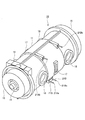
図1,2に示すように、内部中空の円筒形をなす高伝熱性材料であるアルミニウム金属製のフレーム11の内部の軸方向中程の内周面には、円筒形をなす固定子12の外周面が当該フレーム11と同軸をなすようにして固定されている。前記固定子12の内部には、回転軸14が同軸をなして貫通するように配設されている。前記回転軸14の両端側は、前記フレーム11の両端側にそれぞれ取り付けられた対をなす環状のブラケット15にそれぞれ回転可能に支持されている。
As shown in FIGS. 1 and 2, a
前記回転軸14の軸方向中程の外周面には、永久磁石13aが前記固定子12の内周面と対向するように当該回転軸14の周方向にわたって配設されると共に、磁性を有する鉄等からなる円筒形のリング13bが当該永久磁石13aを当該回転軸14の外周面に固定するように嵌合しており、当該永久磁石13a及び当該リング13b等により、回転子13が構成されている。言い換えると、前記回転軸14は、前記回転子13の内部を貫通するように当該回転子13に取り付けられているのである。そして、前記回転子13は、前記固定子12の内周面と前記リング13bの外周面との間に規定間隔のギャップGを有するように当該固定子12の内部に設けられている。
A
前記フレーム11の周面の軸方向両端寄りには、当該フレーム11の外部と内部とを連通させる第一の供給口16と排出口18とが互いに対向するようにそれぞれ形成されている。前記フレーム11の周面の軸方向中程には、前記固定子12の軸方向中央部分に径方向へ沿って形成されて前記ギャップGに連通するダクト12aと当該フレーム11の外部とを連通させる第二の供給口17が、周方向に沿って等間隔で複数(本実施形態では二つ)形成されている。
A
前記フレーム11の外周面と内周面との間の軸方向中程には、螺旋状をなすステンレス(SUS)製の冷却水管21A,21B(図3参照)が当該フレーム11の一方端寄りと他方端寄りとで対をなして内装されるように鋳込まれており、当該冷却水管21A,21Bは、当該フレーム11の軸方向中央寄りの下方位置に、当該フレーム11の外部へ露出する供給口21Aa,21Baを有し、当該フレーム11の軸方向端部寄りの上方位置に、当該フレーム11の外部へ露出する排出口21Ab,21Bbを有している。
In the middle in the axial direction between the outer peripheral surface and the inner peripheral surface of the
なお、図中、19はコイルエンドである。
In the figure,
このような本実施形態に係る回転電機10においては、図4に示すように、前記供給口16,17から前記フレーム11の内部に冷却風1を送給すると共に、前記供給口21Aa,21Baから前記冷却水管21A,21Bの内部に冷却水2を送給する。
In the rotating
すると、図5に示すように、前記第一の供給口16に送給された冷却風1は、前記フレーム11の内部の軸方向両端寄りを流通して、前記コイルエンド19等を冷却しながら前記排出口18から当該フレーム11の外部へ排出され、前記第二の供給口17に送給された冷却風1は、前記固定子12の前記ダクト12a内を流通して当該固定子12を軸方向中央部分から冷却しながら前記ギャップGに到達し、軸方向中央部分から両端側へ向かって分岐するように当該ギャップG内を流通して当該固定子12の内周面と前記回転子13の外周面とを冷却しながら当該ギャップGから流出し、上記第一の供給口16から送給された冷却風1と合流して上記排出口18から上記フレーム11の外部へ排出される。
Then, as shown in FIG. 5, the
他方、前記供給口21Aa,21Baに送給された冷却水2は、前記冷却水管21A,21B内を流通する、すなわち、前記固定子12の外周面に対して軸方向中央側から両方の端部側へ各々向かうように螺旋状に流通しながら前記フレーム11を介して当該固定子12を外周面から全体的に冷却して、前記排出口21Ab,21Bbから排出される。
On the other hand, the
つまり、本実施形態に係る回転電機10では、前記第一の供給口16に送給する冷却風1により、コイルエンド19を冷却するだけでなく、前記第二の供給口17に送給する冷却風1により、前記固定子12の最も温度の高い軸方向中央部分の内部を径方向外側から径方向内側へ向かって空冷してから当該固定子12の内周面と前記回転子13の外周面とを軸方向中央部分から端部側へ向かって空冷すると共に、前記供給口21Aa,21Baに送給する冷却水2により、上記固定子12の外周面を最も温度の高い軸方向中央部分から端部側へ向かって水冷するようにしたのである。
That is, in the rotating
このため、本実施形態に係る回転電機10においては、高出力化への対応で前記固定子12の内部や前記コイルエンド19等の巻線部分に厚手の高圧絶縁紙を使用したり、高速回転化への対応で前記永久磁石13aを前記リング13bで覆うように前記回転子13を前記回転軸14に固定しても、当該固定子12の内部及び上記コイルエンド19等の巻線部分や、当該回転子13の上記永久磁石13a部分を効果的に冷却して、温度上昇を大幅に抑制することができる。
For this reason, in the rotating
したがって、本実施形態に係る回転電機10によれば、冷却性能を大きく向上させることができるので、高出力化や高速回転化を更に図ることができる。
Therefore, according to the rotating
また、二本の冷却水管21A,21Bに冷却水2を並列的に流通させて前記固定子12を冷却するようにしたことから、当該冷却水管21A,21B内の圧力損失を増加させることなく、冷却水2の単位時間当たりの流量を増加させることができるので、冷却水2による冷却性能を大きく向上させることができる。
Further, since the
本発明に係る回転電機は、冷却性能を大きく向上させて、高出力化や高速回転化を更に図ることができるので、産業上、極めて有益に利用することができる。 INDUSTRIAL APPLICABILITY The rotating electric machine according to the present invention can greatly improve the cooling performance and further increase the output and the high-speed rotation.
1 冷却風
2 冷却水
10 回転電機
11 フレーム
12 固定子
12a ダクト
13 回転子
13a 永久磁石
13b リング
14 回転軸
15 ブラケット
16 第一の供給口
17 第二の供給口
18 排出口
19 コイルエンド
21A,21B 冷却水管
21Aa,21Ba 供給口
21Ab,21Bb 排出口
G ギャップ
DESCRIPTION OF
Claims (2)
前記フレームの内部に取り付けられた円筒形をなす固定子と、
前記固定子との間にギャップを有するように当該固定子の内部に配設された円筒形をなす回転子と、
前記回転子の内部を貫通するように当該回転子に取り付けられた回転軸と、
前記フレームに取り付けられて前記回転軸を回転可能に支持するブラケットと
を備えている回転電機において、
前記固定子が、軸方向中央部分に径方向へ沿って形成されて前記ギャップに連通するダクトを有し、
前記フレームが、冷却風を軸方向両端寄りの内部に供給する第一の供給口及び内部の冷却風を外部へ排出する排出口をそれぞれ有すると共に、冷却風を前記固定子の前記ダクトへ供給する第二の供給口を有し、
前記フレームの軸方向中程の一方端寄りと他方端寄りとに対をなすように配設されて冷却水を供給される供給口を軸方向中央寄りに有すると共に冷却水を排出する排出口を軸方向端部寄りに有する冷却水管を備え、
前記第二の供給口が、前記両冷却水管の供給口間に配置されていることを特徴とする回転電機。 A cylindrical frame,
A cylindrical stator mounted inside the frame,
A cylindrical rotor disposed inside the stator so as to have a gap with the stator,
A rotating shaft attached to the rotor so as to penetrate the inside of the rotor,
And a bracket attached to the frame to rotatably support the rotating shaft.
The stator has a duct formed radially in a central portion in the axial direction and communicating with the gap,
The frame has a first supply port for supplying cooling air to the interior near both ends in the axial direction, and a discharge port for discharging the internal cooling air to the outside, and supplies the cooling air to the duct of the stator. Has a second supply port,
A discharge port, which is provided so as to form a pair near one end and near the other end in the middle of the frame in the axial direction and has a supply port for supplying cooling water near the center in the axial direction, and a discharge port for discharging cooling water. A cooling water pipe having an axial end portion is provided,
The rotating electric machine wherein the second supply port is disposed between the supply ports of the cooling water pipes.
前記フレームが、前記冷却水管を外周面と内周面との間に内装するように鋳込まれたアルミニウム金属製である
ことを特徴とする回転電機。 The rotating electric machine according to claim 1 ,
The rotating electric machine, wherein the frame is made of an aluminum metal cast so as to house the cooling water pipe between an outer peripheral surface and an inner peripheral surface.
Priority Applications (6)
| Application Number | Priority Date | Filing Date | Title |
|---|---|---|---|
| JP2018042614A JP6624223B2 (en) | 2018-03-09 | 2018-03-09 | Rotating electric machine |
| CN201980017516.8A CN111819771B (en) | 2018-03-09 | 2019-02-26 | Electric machine |
| EP19764130.1A EP3764524B1 (en) | 2018-03-09 | 2019-02-26 | Dynamo-electric machine |
| PCT/JP2019/007163 WO2019172007A1 (en) | 2018-03-09 | 2019-02-26 | Dynamo-electric machine |
| US16/978,302 US11025136B2 (en) | 2018-03-09 | 2019-02-26 | Dynamo-electric machine |
| RU2020131483A RU2742819C1 (en) | 2018-03-09 | 2019-02-26 | Dynamo-electric machine |
Applications Claiming Priority (1)
| Application Number | Priority Date | Filing Date | Title |
|---|---|---|---|
| JP2018042614A JP6624223B2 (en) | 2018-03-09 | 2018-03-09 | Rotating electric machine |
Publications (2)
| Publication Number | Publication Date |
|---|---|
| JP2019161764A JP2019161764A (en) | 2019-09-19 |
| JP6624223B2 true JP6624223B2 (en) | 2019-12-25 |
Family
ID=67846661
Family Applications (1)
| Application Number | Title | Priority Date | Filing Date |
|---|---|---|---|
| JP2018042614A Active JP6624223B2 (en) | 2018-03-09 | 2018-03-09 | Rotating electric machine |
Country Status (6)
| Country | Link |
|---|---|
| US (1) | US11025136B2 (en) |
| EP (1) | EP3764524B1 (en) |
| JP (1) | JP6624223B2 (en) |
| CN (1) | CN111819771B (en) |
| RU (1) | RU2742819C1 (en) |
| WO (1) | WO2019172007A1 (en) |
Families Citing this family (2)
| Publication number | Priority date | Publication date | Assignee | Title |
|---|---|---|---|---|
| JP6912028B1 (en) * | 2020-03-18 | 2021-07-28 | 株式会社明電舎 | Rotating machine |
| WO2021187166A1 (en) * | 2020-03-18 | 2021-09-23 | 株式会社明電舎 | Rotating machine |
Family Cites Families (24)
| Publication number | Priority date | Publication date | Assignee | Title |
|---|---|---|---|---|
| JPH0739329Y2 (en) * | 1986-10-23 | 1995-09-06 | 株式会社東芝 | Rotating electric machine |
| SU1713024A1 (en) * | 1989-08-22 | 1992-02-15 | Всесоюзный научно-исследовательский, проектно-конструкторский и технологический институт взрывозащищенного и рудничного электрооборудования | Frame of enclosed electric machine |
| JPH04180393A (en) * | 1990-11-14 | 1992-06-26 | Fujitsu General Ltd | Private branch exchange device |
| JPH0644378U (en) * | 1992-11-20 | 1994-06-10 | 株式会社明電舎 | Rotating electric machine |
| JPH08322188A (en) * | 1995-05-26 | 1996-12-03 | Meidensha Corp | Forced air cooling motor |
| DE19526689A1 (en) * | 1995-07-21 | 1997-01-23 | Abb Management Ag | Tube generator |
| DE69731209D1 (en) * | 1996-08-09 | 2004-11-18 | Turbo Genset Co Ltd | ROTATING ELECTRICAL MACHINES |
| US5859482A (en) * | 1997-02-14 | 1999-01-12 | General Electric Company | Liquid cooled electric motor frame |
| JP3877899B2 (en) | 1999-03-09 | 2007-02-07 | 三菱電機株式会社 | AC generator for vehicles |
| JP2001045713A (en) * | 1999-07-30 | 2001-02-16 | Hitachi Ltd | Dynamo-electric machine |
| JP3806303B2 (en) | 2000-12-11 | 2006-08-09 | 三菱重工業株式会社 | Cooling structure in generator |
| DE10122425B4 (en) * | 2001-05-09 | 2006-06-01 | Siemens Ag | Electric machine |
| DE502004010520D1 (en) * | 2004-07-30 | 2010-01-28 | Brose Fahrzeugteile | electric motor |
| JP2006161590A (en) * | 2004-12-03 | 2006-06-22 | Denso Corp | Starter |
| DE102006036289B4 (en) * | 2006-08-03 | 2010-04-08 | Siemens Ag | Engine system and method for operating an engine system |
| JP2008301646A (en) | 2007-06-01 | 2008-12-11 | Aichi Electric Co Ltd | Motor cooling apparatus |
| JP5470015B2 (en) * | 2009-12-04 | 2014-04-16 | 株式会社日立製作所 | Rotating electric machine |
| JP5260591B2 (en) | 2010-03-30 | 2013-08-14 | 株式会社日立製作所 | Permanent magnet rotating electrical machine and wind power generation system |
| JP2013207944A (en) * | 2012-03-29 | 2013-10-07 | Hitachi Automotive Systems Ltd | Rotary electric machine for vehicle |
| JP6016230B2 (en) * | 2012-09-27 | 2016-10-26 | 澤藤電機株式会社 | Generator |
| US9461523B2 (en) * | 2013-12-12 | 2016-10-04 | Baldor Electric Company | Two phase gap cooling of an electrical machine |
| KR20160000909A (en) * | 2014-06-25 | 2016-01-06 | 현대모비스 주식회사 | Water-cooled moter |
| CN204886564U (en) * | 2015-05-11 | 2015-12-16 | 哈尔滨电机厂有限责任公司 | Through type cooling through -flow hydraulic generator ventilation unit |
| CN107147260A (en) * | 2017-07-19 | 2017-09-08 | 沈阳工业大学 | A kind of axial permanent magnetic auxiliary radial direction magnetic resistance high-speed electric expreess locomotive with combination cooling structure |
-
2018
- 2018-03-09 JP JP2018042614A patent/JP6624223B2/en active Active
-
2019
- 2019-02-26 CN CN201980017516.8A patent/CN111819771B/en active Active
- 2019-02-26 EP EP19764130.1A patent/EP3764524B1/en active Active
- 2019-02-26 RU RU2020131483A patent/RU2742819C1/en active
- 2019-02-26 WO PCT/JP2019/007163 patent/WO2019172007A1/en active Application Filing
- 2019-02-26 US US16/978,302 patent/US11025136B2/en active Active
Also Published As
| Publication number | Publication date |
|---|---|
| RU2742819C1 (en) | 2021-02-11 |
| JP2019161764A (en) | 2019-09-19 |
| EP3764524A4 (en) | 2021-04-21 |
| CN111819771B (en) | 2021-07-16 |
| EP3764524A1 (en) | 2021-01-13 |
| US20210006131A1 (en) | 2021-01-07 |
| EP3764524B1 (en) | 2022-07-27 |
| CN111819771A (en) | 2020-10-23 |
| US11025136B2 (en) | 2021-06-01 |
| WO2019172007A1 (en) | 2019-09-12 |
Similar Documents
| Publication | Publication Date | Title |
|---|---|---|
| JP6624223B2 (en) | Rotating electric machine | |
| JP2015104214A (en) | Rotary electric machine | |
| WO2017082023A1 (en) | Dynamo-electric machine | |
| JP2012100521A (en) | Case for rotary electric machine | |
| JP2007325358A (en) | Motor | |
| JP2007089255A (en) | Dynamo-electric machine | |
| EP3856451B1 (en) | Multi-spindle operating head | |
| JP2017192163A (en) | Totally-enclosed dynamo-electric machine | |
| JP2013034332A (en) | Rotary electric machine | |
| JP2010187490A (en) | Rotary electric machine | |
| JP6686295B2 (en) | Rotating electric machine | |
| JP5724301B2 (en) | Generator cooling structure | |
| JP2019154197A (en) | Rotary electric machine | |
| JP2017200354A (en) | Brushless rotary electric machine | |
| US9793767B2 (en) | Method and assembly for cooling an electric machine | |
| JP2019054650A (en) | Totally-closed fan-cooled dynamo-electric machine | |
| JP6325339B2 (en) | Rotating electrical machine system and wind power generation system | |
| JP5083891B2 (en) | Cantilever induction heating roller device | |
| JP2020141544A (en) | Rotary electric machine | |
| KR101758989B1 (en) | rotor assembly for generator | |
| JP2010187489A (en) | Rotary electric machine | |
| JP2013158161A (en) | Rotary electric machine | |
| KR100656270B1 (en) | Induction generator advanced heat conduction of stator core | |
| JP7082957B2 (en) | Rotor cooling structure and turbine generator | |
| JP2011055625A (en) | Rotor of rotary electrical machine |
Legal Events
| Date | Code | Title | Description |
|---|---|---|---|
| A621 | Written request for application examination |
Free format text: JAPANESE INTERMEDIATE CODE: A621 Effective date: 20190308 |
|
| A521 | Request for written amendment filed |
Free format text: JAPANESE INTERMEDIATE CODE: A523 Effective date: 20190320 |
|
| A871 | Explanation of circumstances concerning accelerated examination |
Free format text: JAPANESE INTERMEDIATE CODE: A871 Effective date: 20190320 |
|
| A975 | Report on accelerated examination |
Free format text: JAPANESE INTERMEDIATE CODE: A971005 Effective date: 20190527 |
|
| RD02 | Notification of acceptance of power of attorney |
Free format text: JAPANESE INTERMEDIATE CODE: A7422 Effective date: 20190529 |
|
| A131 | Notification of reasons for refusal |
Free format text: JAPANESE INTERMEDIATE CODE: A131 Effective date: 20190618 |
|
| RD04 | Notification of resignation of power of attorney |
Free format text: JAPANESE INTERMEDIATE CODE: A7424 Effective date: 20190529 |
|
| A521 | Request for written amendment filed |
Free format text: JAPANESE INTERMEDIATE CODE: A523 Effective date: 20190809 |
|
| TRDD | Decision of grant or rejection written | ||
| A01 | Written decision to grant a patent or to grant a registration (utility model) |
Free format text: JAPANESE INTERMEDIATE CODE: A01 Effective date: 20191029 |
|
| A61 | First payment of annual fees (during grant procedure) |
Free format text: JAPANESE INTERMEDIATE CODE: A61 Effective date: 20191111 |
|
| R150 | Certificate of patent or registration of utility model |
Ref document number: 6624223 Country of ref document: JP Free format text: JAPANESE INTERMEDIATE CODE: R150 |