JP5257622B2 - Light bulb shaped lamp and lighting equipment - Google Patents
Light bulb shaped lamp and lighting equipment Download PDFInfo
- Publication number
- JP5257622B2 JP5257622B2 JP2010042528A JP2010042528A JP5257622B2 JP 5257622 B2 JP5257622 B2 JP 5257622B2 JP 2010042528 A JP2010042528 A JP 2010042528A JP 2010042528 A JP2010042528 A JP 2010042528A JP 5257622 B2 JP5257622 B2 JP 5257622B2
- Authority
- JP
- Japan
- Prior art keywords
- base
- substrate
- screw
- light emitting
- light
- Prior art date
- Legal status (The legal status is an assumption and is not a legal conclusion. Google has not performed a legal analysis and makes no representation as to the accuracy of the status listed.)
- Active
Links
Images


Classifications
-
- F—MECHANICAL ENGINEERING; LIGHTING; HEATING; WEAPONS; BLASTING
- F21—LIGHTING
- F21V—FUNCTIONAL FEATURES OR DETAILS OF LIGHTING DEVICES OR SYSTEMS THEREOF; STRUCTURAL COMBINATIONS OF LIGHTING DEVICES WITH OTHER ARTICLES, NOT OTHERWISE PROVIDED FOR
- F21V19/00—Fastening of light sources or lamp holders
- F21V19/001—Fastening of light sources or lamp holders the light sources being semiconductors devices, e.g. LEDs
- F21V19/003—Fastening of light source holders, e.g. of circuit boards or substrates holding light sources
- F21V19/0055—Fastening of light source holders, e.g. of circuit boards or substrates holding light sources by screwing
-
- F—MECHANICAL ENGINEERING; LIGHTING; HEATING; WEAPONS; BLASTING
- F21—LIGHTING
- F21K—NON-ELECTRIC LIGHT SOURCES USING LUMINESCENCE; LIGHT SOURCES USING ELECTROCHEMILUMINESCENCE; LIGHT SOURCES USING CHARGES OF COMBUSTIBLE MATERIAL; LIGHT SOURCES USING SEMICONDUCTOR DEVICES AS LIGHT-GENERATING ELEMENTS; LIGHT SOURCES NOT OTHERWISE PROVIDED FOR
- F21K9/00—Light sources using semiconductor devices as light-generating elements, e.g. using light-emitting diodes [LED] or lasers
- F21K9/20—Light sources comprising attachment means
- F21K9/23—Retrofit light sources for lighting devices with a single fitting for each light source, e.g. for substitution of incandescent lamps with bayonet or threaded fittings
- F21K9/232—Retrofit light sources for lighting devices with a single fitting for each light source, e.g. for substitution of incandescent lamps with bayonet or threaded fittings specially adapted for generating an essentially omnidirectional light distribution, e.g. with a glass bulb
-
- F—MECHANICAL ENGINEERING; LIGHTING; HEATING; WEAPONS; BLASTING
- F21—LIGHTING
- F21V—FUNCTIONAL FEATURES OR DETAILS OF LIGHTING DEVICES OR SYSTEMS THEREOF; STRUCTURAL COMBINATIONS OF LIGHTING DEVICES WITH OTHER ARTICLES, NOT OTHERWISE PROVIDED FOR
- F21V29/00—Protecting lighting devices from thermal damage; Cooling or heating arrangements specially adapted for lighting devices or systems
- F21V29/50—Cooling arrangements
- F21V29/70—Cooling arrangements characterised by passive heat-dissipating elements, e.g. heat-sinks
- F21V29/74—Cooling arrangements characterised by passive heat-dissipating elements, e.g. heat-sinks with fins or blades
- F21V29/77—Cooling arrangements characterised by passive heat-dissipating elements, e.g. heat-sinks with fins or blades with essentially identical diverging planar fins or blades, e.g. with fan-like or star-like cross-section
- F21V29/773—Cooling arrangements characterised by passive heat-dissipating elements, e.g. heat-sinks with fins or blades with essentially identical diverging planar fins or blades, e.g. with fan-like or star-like cross-section the planes containing the fins or blades having the direction of the light emitting axis
-
- F—MECHANICAL ENGINEERING; LIGHTING; HEATING; WEAPONS; BLASTING
- F21—LIGHTING
- F21Y—INDEXING SCHEME ASSOCIATED WITH SUBCLASSES F21K, F21L, F21S and F21V, RELATING TO THE FORM OR THE KIND OF THE LIGHT SOURCES OR OF THE COLOUR OF THE LIGHT EMITTED
- F21Y2115/00—Light-generating elements of semiconductor light sources
- F21Y2115/10—Light-emitting diodes [LED]
Description
本発明は、光源として半導体発光素子を用いた電球形ランプ、およびこの電球形蛍光ランプを用いた照明器具に関する。 The present invention relates to a light bulb shaped lamp using a semiconductor light emitting element as a light source and a lighting fixture using the light bulb shaped fluorescent lamp.
従来、半導体発光素子としてLED素子を用いた電球形ランプでは、金属製の基体の一端側にLED素子を有する発光モジュールが取り付けられているとともにこの発光モジュールを覆ってグローブが取り付けられ、基体の他端側に口金が取り付けられ、基体内に点灯回路が収納されている。 Conventionally, in a light bulb-type lamp using an LED element as a semiconductor light emitting element, a light emitting module having an LED element is attached to one end of a metal base, and a glove is attached to cover the light emitting module. A base is attached to the end side, and a lighting circuit is accommodated in the base.
発光モジュールは、複数のLED素子を基板上に直接的に実装するCOB(Chip On Board)モジュールで、基体への熱伝導性のよい金属製の基板が用いられる場合、基板の一面に絶縁層が形成され、この絶縁層上に配線パターンが形成されているとともに接着剤によって複数のLED素子が実装され、これらLED素子と配線パターンとがワイヤボンディングによって電気的に接続され、複数のLED素子全体が蛍光体を混入した封止樹脂で覆われている(例えば、特許文献1参照。)。 The light emitting module is a COB (Chip On Board) module in which a plurality of LED elements are directly mounted on a substrate. When a metal substrate with good thermal conductivity to the base is used, an insulating layer is provided on one surface of the substrate. A wiring pattern is formed on the insulating layer, and a plurality of LED elements are mounted by an adhesive, and the LED elements and the wiring pattern are electrically connected by wire bonding. It is covered with a sealing resin mixed with a phosphor (for example, see Patent Document 1).
また、発光モジュールの基板から基体への熱伝導性を良好にするために、基板を基体にねじで締め付けて固定し、基板を基体に密着させることが行われている。 Further, in order to improve the thermal conductivity from the substrate to the base of the light emitting module, the substrate is fastened to the base with a screw and fixed, and the base is brought into close contact with the base.
COBモジュール方式の発光モジュールでは、基板へのLED素子の実装方法として、基板の一面に絶縁層を形成し、この絶縁層上に接着剤で複数のLED素子を実装するようにしているが、LED素子から基板への熱伝導性の向上、および発光モジュールの製造工程を簡略化して発光モジュールを安価に構成するために、絶縁層の形成を省略し、金属製の基板の一面に接着剤で複数のLED素子を実装することが考えられる。 In the COB module type light emitting module, as an LED element mounting method on a substrate, an insulating layer is formed on one surface of the substrate, and a plurality of LED elements are mounted on the insulating layer with an adhesive. In order to improve the thermal conductivity from the element to the substrate and to simplify the manufacturing process of the light emitting module and to construct the light emitting module at low cost, the formation of the insulating layer is omitted, and a plurality of adhesives are applied to one surface of the metal substrate. It is conceivable to mount the LED element.
この実装方法の場合、基板が基体に電気的にも接触するとともに、基板を基体に固定する金属製のねじが基板と基体とに電気的にも接触することになり、通常の使用状況では基板とLED素子やワイヤボンディングのワイヤとの間の絶縁距離が確保されていて問題ないが、例えば点灯回路の異常発生時などに、LED素子やワイヤボンディングのワイヤに高電圧がかかって基板との間で放電した場合、基板およびねじに電気が流れ、この基板およびねじから外部に露出する基体へ電気が流れるおそれがある。 In the case of this mounting method, the substrate is in electrical contact with the base, and a metal screw that fixes the substrate to the base is also in electrical contact with the substrate and the base. There is no problem because the insulation distance between the LED element and the wire for wire bonding is secured, but for example, when an abnormality occurs in the lighting circuit, a high voltage is applied to the LED element or the wire for wire bonding to the substrate. In the case of discharging, electricity flows through the substrate and the screw, and there is a possibility that electricity flows from the substrate and the screw to the substrate exposed to the outside.
本発明は、このような点に鑑みなされたもので、基板に電気が流れるような異常発生時においても、基体に電気が流れるのを確実に防止できる電球形ランプおよび照明器具を提供することを目的とする。 The present invention has been made in view of the above points, and provides a light bulb shaped lamp and a lighting fixture that can reliably prevent electricity from flowing to a base even when an abnormality occurs where electricity flows to a substrate. Objective.
請求項1に記載の電球形ランプは、一端側にねじ取付孔が形成された基体と;基板の一面に半導体発光素子が実装された発光部およびその周辺域を有し、基体の一端側に配置された発光モジュールと;発光モジュールの発光部が露出する開口部、およびねじ挿通孔を備えた絶縁体と;絶縁体のねじ挿通孔を介して、基体のねじ取付孔に取り付けられたねじと;基体の他端側に設けられた点灯回路および口金と;を具備し、絶縁体には、一面側にねじ頭部を収容する凹部、凹部と連通してねじ軸部が挿通されるねじ挿通孔、他面側に基板に嵌り込む位置決め突部が形成されており、凹部、ねじ挿通孔、および位置決め突部は基体のねじ取付孔と同軸であるものである。 The light bulb shaped lamp according to claim 1 has a base having a screw mounting hole formed on one end thereof; a light emitting portion having a semiconductor light emitting element mounted on one surface of the substrate and a peripheral area thereof; arranged light-emitting module and, opening the light emitting portion of the light-emitting module is exposed, an insulator having a contact and screw insertion hole; through the screw insertion hole of the insulator, attached to screw mounting holes of the base screw And a lighting circuit and a base provided on the other end side of the base body, and the insulator includes a recess accommodating the screw head on one side, and a screw shaft through which the screw shaft portion is inserted. insertion holes, the other side is positioned protrusion formed fitted to the substrate, the recess, the screw insertion hole, and positioning projections are screw mounting holes coaxial der shall substrate.
本発明および以下の発明において、特に指定しない限り用語の定義および技術的意味は次による。 In the present invention and the following inventions, definitions and technical meanings of terms are as follows unless otherwise specified.
基板は、例えば、アルミニウムなどの金属製で、半導体発光素子を実装する一面に絶縁層が形成されていなくてもよい。半導体発光素子は、例えば、LED素子やEL素子などが含まれる。発光部は、例えば、半導体発光素子がLED素子の場合に、基板の一面に接着剤によって複数のLED素子が実装され、複数のLED素子と基板上に配置された端子部とがワイヤボンディングによって電気的に接続され、複数のLED素子全体が蛍光体を混入した封止樹脂で覆われて形成されている。これにより、発光モジュールは、例えば、複数のLED素子が基板上に直接的に実装されるCOB(Chip On Board)モジュールで構成されている。しかし、本発明は、COBに限定されるものではなく、SMD(Surface Mount Device)形のものを実施するようなものであってもよい。 The substrate is made of a metal such as aluminum, for example, and the insulating layer may not be formed on one surface on which the semiconductor light emitting element is mounted. Examples of the semiconductor light emitting element include an LED element and an EL element. For example, when the semiconductor light-emitting element is an LED element, the light-emitting unit includes a plurality of LED elements mounted on one surface of the substrate with an adhesive, and the plurality of LED elements and the terminal unit disposed on the substrate are electrically connected by wire bonding. The plurality of LED elements are entirely covered with a sealing resin mixed with a phosphor. Thereby, the light emitting module is comprised by the COB (Chip On Board) module by which a some LED element is directly mounted on a board | substrate, for example. However, the present invention is not limited to the COB, and may be an SMD (Surface Mount Device) type.
基体は、例えば、アルミニウムなどの金属製で、外周面には放熱性を向上させるための放熱フィンを設けてもよい。 The base is made of a metal such as aluminum, for example, and a heat radiating fin for improving heat dissipation may be provided on the outer peripheral surface.
絶縁材は、例えば、シリコーン樹脂やシリコーンゴムなどの絶縁性、熱伝導性および弾性を有するシートが好ましいが、これに限定されるものではない。シートの場合、その弾性によって基板と基体との密着性を高めることが可能となる。 The insulating material is preferably a sheet having insulating properties, thermal conductivity and elasticity such as silicone resin and silicone rubber, but is not limited thereto. In the case of a sheet, it is possible to enhance the adhesion between the substrate and the substrate due to its elasticity.
ねじは、例えば、金属製で、頭部、およびねじ山が形成されたねじ軸部を有し、1個または複数個が用いられる。 The screw is made of, for example, metal, has a head portion and a screw shaft portion on which a screw thread is formed, and one or a plurality of screws are used.
絶縁体は、例えば、絶縁性を有する合成樹脂製で、少なくともねじの係合部分においてねじと基板との間に介在するように設けられていればよく、また、ねじが複数の場合には、複数の係合部分を一体に形成することにより1部品で構成するようにしてもよい。 The insulator may be made of, for example, a synthetic resin having insulation properties and provided to be interposed between the screw and the substrate at least at the engagement portion of the screw. A plurality of engaging portions may be formed as a single component by forming them integrally.
口金は、例えば、E26形やE17形などの一般照明電球用のソケットに接続可能なものが含まれる。 Examples of the cap include those that can be connected to a socket for general lighting bulbs such as E26 type and E17 type.
点灯回路は、例えば、定電流の直流電力を出力する電源回路を有し、この電源回路の出力側に接続されている配線を基体内を通じて一端側に引き出し、配線の先端のコネクタを基板に配置されているコネクタに接続することにより、半導体発光素子に電力供給可能とする。点灯回路は基体内に収納されるが、点灯回路の一部が口金内に収納されていてもよい。 The lighting circuit has, for example, a power supply circuit that outputs constant-current DC power, and the wiring connected to the output side of the power supply circuit is drawn out to one end through the base, and the connector at the tip of the wiring is arranged on the substrate By connecting to the connected connector, power can be supplied to the semiconductor light emitting element. Although the lighting circuit is housed in the base, a part of the lighting circuit may be housed in the base.
請求項2に記載の照明器具は、器具本体と;器具本体に装着される請求項1に記載の電球形ランプと;を具備しているものである。 Lighting appliance according to 請 Motomeko 2, the instrument body and; those that include a; and self-ballasted lamp according to claim 1 mounted on the instrument body.
請求項1に記載の電球形ランプによれば、発光モジュールの基板を基体に固定するねじと発光モジュールの基板との間に絶縁体を介在するため、基板に電気が流れるような異常発生時においても、基体に電気が流れるのを確実に防止できる。 According to the light bulb shaped lamp according to claim 1, since an insulator is interposed between the screw for fixing the substrate of the light emitting module to the base and the substrate of the light emitting module, an abnormality occurs when electricity flows through the substrate. However, it is possible to reliably prevent electricity from flowing to the base.
さらに、絶縁体には、一面側にねじ頭部を収容する凹部、凹部と連通してねじ軸部が挿通されるねじ挿通孔、他面側に基板に嵌り込む位置決め突部が形成されており、凹部、ねじ挿通孔、および位置決め突部は基体のねじ取付孔と同軸となるようにできる。 Further, the insulator, recess for accommodating the screw head portion on one side, a screw insertion hole through which the screw shaft portion is inserted through the recess and the communication, and the positioning projections fit into the substrate on the other surface side is formed The recess, the screw insertion hole, and the positioning protrusion can be coaxial with the screw mounting hole of the base.
請求項2に記載の照明器具によれば、請求項1の電球形ランプの作用効果が得られる照明器具を提供できる。 According to the lighting device according to claim 2, it is possible to provide a luminaire effects of the self-ballasted lamp 請 Motomeko 1 is obtained.
以下、本発明の実施の形態を、図面を参照して説明する。 Hereinafter, embodiments of the present invention will be described with reference to the drawings.
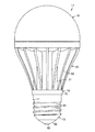
図1ないし図6に第1の実施の形態を示す。図1ないし図4において、11は電球形ランプで、この電球形ランプ11は、金属製の基体12、この基体12の一端側(電球形ランプ11のランプ軸の一端側)に取り付けられた発光モジュールユニット13、基体12の他端側に取り付けられた絶縁性を有するカバー14、このカバー14の他端側に取り付けられた口金15、発光モジュールユニット13を覆って基体12の一端側に取り付けられた透光性を有するグローブ16、および基体12と口金15との間でカバー14の内側に収納された点灯回路17を備えている。
1 to 6 show a first embodiment. 1 to 4,
まず、基体12は、熱伝導性が優れた例えばアルミニウムなど金属材料によって一体形成されており、中央域には他端側へ向けて開口する胴体部21が形成され、この胴体部21の周囲にランプ軸方向に沿った複数の放熱フィン22が放射状に突出形成されている。放熱フィン22は、基体12の他端側から一端側へと径方向の突出量が徐々に大きくなるように傾斜して形成されており、グローブ16と組み合わせた際に電球形の形状に近似するように構成されている。
First, the
基体12の一端側の面には、発光モジュールユニット13が取り付けられる平面状の取付面23が形成されている。この取付面23には、発光モジュールユニット13の後述する絶縁シートを位置決めするための複数の位置決め突起24、発光モジュールユニット13をねじ止めするための複数の取付孔25、および点灯回路17と発光モジュールユニット13側とを電気的に接続するコネクタやリード線を通すための配線孔26が形成されている。さらに、基体12には、胴体部21内に配置したカバー14をこのカバー14の内側からねじ止めするための取付孔27が貫通形成されている。
A
基体12の一端側には、ランプ軸の中心から外れた位置に基体12の一端側と他端側である胴体部21の内側とを連通する孔部28がランプ軸方向に沿って形成され、基体12の一端側の面に孔部28の一端側から基体12の周辺域へ向けて溝部29が連通形成され、これら孔部28および溝部29によって点灯回路17と発光モジュールユニット13側とを電気的に接続するコネクタやリード線を通すための配線孔26が形成されている。
On one end side of the
基体12の一端側の周辺域には、グローブ16を取り付ける環状のグローブ取付部30が突出形成されている。このグローブ取付部30の内周部には、グローブ取付部30の先端から離反した取付面23に寄った位置に、全周に亘って係止溝31が形成され、さらに、グローブ取付部30の周方向の複数箇所であって例えば周方向に等間隔となる4箇所に、ランプ軸方向に沿って回転止め溝32が形成されている。
In the peripheral area on one end side of the
次に、発光モジュールユニット13は、発光モジュール41、発光モジュール41を基体12に固定する複数のねじ42、発光モジュール41と基体12との間に介在される絶縁材としての絶縁シート43、および発光モジュール41上に配置されてねじ42と発光モジュール41との間に介在される絶縁体としての絶縁カラー44を備えている。
Next, the light emitting
発光モジュール41は、例えばアルミニウムなどの金属材料で形成された長方形状の基板47、およびこの基板47の一端側の一面である実装面の中央域に形成された円形の発光部48を有している。
The
発光部48は、図5に示すように、基板47の金属面上に、複数の半導体発光素子としてのLED素子であるLEDチップ49が実装するCOB(Chip On Board)方式が用いられている。すなわち、基板47の金属面上に、複数のLEDチップ49がマトリクス状に配列して実装する各実装位置に対応してシリコーン樹脂などの接着剤50が所定の間隔をあけて塗布され、これら各接着剤50に押し付けるようにして各LEDチップ49が所定の間隔をあけて接着固定され、隣り合うLEDチップ49がワイヤボンディング処理によるワイヤ51によって直列に電気的に接続され、複数のLEDチップ49全体が蛍光体を混入した例えばシリコーン樹脂などの透明樹脂である封止樹脂52で覆われて封止されている。
As shown in FIG. 5, the
LEDチップ49には例えば青色光を発するLEDチップが用いられ、封止樹脂にはLEDチップ49からの青色光の一部により励起されて黄色光を放射する蛍光体が混入されている。したがって、LEDチップ49および封止樹脂52などによって発光部48が構成され、この発光部48の表面である封止樹脂52の表面が発光面53となり、この発光面53から白色系の照明光が放射される。
For example, an LED chip that emits blue light is used as the
基板47の実装面には、基板47に対して絶縁状態で図示しない配線パターンが形成され、この配線パターンに、複数のLEDチップ49を直列に接続するワイヤ51の各端部が接続されているとともに、基板47上の1つの隅部に実装されるコネクタ54が接続されている。
A wiring pattern (not shown) is formed on the mounting surface of the
基板47の隅部でコネクタ54が実装されていない対角線上に位置する2箇所の隅部に、ねじ42が挿通される挿通孔55が形成されている。これら挿通孔55は、基体12の各取付孔25と同軸となる位置に形成され、ねじ42よりも大径で、挿通孔55の中心に挿通されるねじ42と基板12との絶縁距離が確保されている。
Insertion holes 55 through which the
また、ねじ42は、金属製で、頭部58、およびねじ山が形成されたねじ軸部59を有している。発光モジュール41を基体12に固定する際には、ねじ軸部59に挿通されるワッシャ60が用いられる。
The
また、絶縁シート43は、例えば、シリコーン樹脂やシリコーンゴムなどの絶縁性、熱伝導性および弾性を有する薄いシートであり、基体12の各取付孔25および基板47の各挿通孔55と同軸となる位置に、ねじ42のねじ軸部59が挿通される挿通孔63が形成されている。
The insulating
また、絶縁カラー44は、例えば、PBT樹脂などの絶縁性を有する合成樹脂製で、基板47の外形範囲内の大きさに形成されていて基板47上に被着されるカラー本体65を有している。カラー本体65の中央域には発光部48が露出する円形の開口部66が形成されているとともにこの開口部66の周囲に発光部48上の周辺域に配置される環状の壁部67が形成されている。
The insulating
図2に示すように、基板47からの壁部67の高さ寸法は、基板47上に配置されるコネクタ54やねじ42の頭部58の影がグローブ16に映るのを防止できるように、発光部48の端部と反対側に位置する壁部67の上端とを結ぶ仮想線aが、コネクタ54やねじ42の頭部58にかからないように設定される。なお、図2では、仮想線aがコネクタ54にかかっているように見えるが、これは断面の方向の関係でこのように見えるだけで、コネクタ54の位置を通るようにした断面では仮想線aがコネクタ54にかからない。
As shown in FIG. 2, the height dimension of the
カラー本体65の四隅のうち、一方の対角線上に位置する隅部にはコネクタ54との干渉を避けるための切欠部68が形成され、他方の対角線上に位置する隅部にはねじ42が係合するねじ係合部69が形成されている。
Of the four corners of the
ねじ係合部69には、一面側にねじ42の頭部58およびワッシャ60が係合して収容される凹部70が形成され、ねじ42のねじ軸部59が挿通される挿通孔71が形成されている。ねじ係合部69の他面側には、基板47の挿通孔55に嵌り込む位置決め突部72が形成されている。これらねじ係合部69の凹部70、挿通孔71および位置決め突部72は、基体12の各取付孔25、基板47の各挿通孔55、および絶縁シート43の挿通孔63と同軸となる位置に形成されている。
The
また、カバー14は、例えばPBT樹脂などの絶縁材料により、他端側へ向けて開口する円筒状に形成されている。カバー14の他端側の外周部には、基体12と口金15との間に介在して互いの間を絶縁する環状の鍔部75が形成され、この鍔部75より他端側で口金15を螺着して取り付けるためのねじ山を有する螺合部76が形成されている。カバー14の一端側の面には、基体12の配線孔26の孔部28に同軸に連通してコネクタやリード線を通すための配線孔77が形成されているとともに、基体12の取付孔27に同軸に連通してねじ止めするための挿通孔78が形成されている。カバー14の内周面には、互いに対向する一対の基板取付溝79がカバー14の中心からオフセットした位置にランプ軸方向に沿って形成されている。
Moreover, the
また、口金15は、例えば、E17形やE26形などの一般照明電球用のソケットに接続可能なもので、カバー14の螺合部76に螺合されて固定されるシェル81、このシェル81の他端側に設けられる絶縁部82、およびこの絶縁部82の頂部に設けられるアイレット83を有している。
The base 15 can be connected to a socket for general lighting bulbs such as E17 type and E26 type, and a
また、グローブ16は、光拡散性を有する合成樹脂製あるいはガラス製などで、半球面形状に形成されている。グローブ16の他端側は開口され、この開口縁部に基体12のグローブ取付部30の内周側に嵌合される嵌合部85が形成されている。嵌合部85には、グローブ取付部30の各回転止め溝32に嵌め込まれる複数の回転止め突起86が形成されているとともに、嵌合部85をグローブ取付部30に嵌合した際にグローブ取付部30の係止溝31に係止される複数の係止爪87が形成されている。
The
また、点灯回路17は、発光モジュール41のLEDチップ49に対して定電流を供給する回路であり、回路を構成する複数の回路素子が実装された回路基板89を有し、この回路基板89がカバー14の基板取付溝79に差し込まれてカバー14内に収納されている。点灯回路17の入力側には、口金15のシェル81およびアイレット83がリード線で電気的に接続されている。点灯回路17の出力側には先端にコネクタ90を有するリード線91が接続され、このコネクタ90およびリード線91がカバー14の配線孔77および基体12の配線孔26を通じて基体12の一端側に引き出され、コネクタ90が発光モジュール41のコネクタ54に接続されている。なお、このコネクタ90の接続作業は、発光モジュール41を基体12にねじ止めする前に行われる。
The
そして、電球形ランプ11を組み立てるには、まず、カバー14を基体12の胴体部21に挿入し、カバー14の内側から挿通孔78を通じて基体12の取付孔27にねじ止めする。続いて、点灯回路17の回路基板89をカバー14の内側に挿入するとともにコネクタ90およびリード線91をカバー14の配線孔77および基体の配線孔26を通じて基体12の一端側に引き出す。続いて、口金15をカバー14の螺合部76に螺合し、接着やかしめによって口金15をカバー14に固定する。
In order to assemble the light bulb shaped
続いて、発光モジュールユニット13を基体12に取り付ける。すなわち、絶縁シート43を基体12の取付面23から突出する複数の位置決め突起24間に位置決めして配置し、発光モジュール41の基板47を絶縁シート43上に配置し、絶縁カラー44を基板47上に被せるとともに各位置決め突部72を基板47の挿通孔55に嵌め込んで位置決めし、ワッシャ60を通した各ねじ42のねじ軸部59を絶縁カラー44の各凹部70および挿通孔71、基板47の挿通孔55、および絶縁シート43の挿通孔63を通じて基体12の取付孔25に螺着し、ねじ42を締め付けて絶縁カラー44、発光モジュール41および絶縁シート43を基体12に固定する。また、予め基体12の一端側に引き出されているコネクタ90およびリード線91は、絶縁シート43および基板47の縁部から配線孔26の溝部29の端部が露出して開口する部分から引き出しておき、発光モジュールユニット13の取付後に、コネクタ90を発光モジュール41のコネクタ54に接続する。これにより、発光モジュール41の基板47が絶縁シート43を介して基体12の取付面23に面接触して密着した状態に取り付けられ、また、発光モジュール41の発光部48の中心がランプ軸の中心に配置される。なお、発光モジュールユニット13の基体12への取付順序は、これに限らず、別の取付順序でもよい。
Subsequently, the light emitting
続いて、基体12のグローブ取付部30の内周にシリコーン樹脂やセメントなどの接着剤を塗布し、グローブ16の各回転止め突起86をグローブ取付部30の各回転止め溝32に位置決めしてグローブ16を基体12に被着することにより、グローブ16の各係止爪87がグローブ取付部30の係止溝31に係止され、グローブ16が基体12に嵌合固定される。これにより、グローブ16が基体12に対して回転止めされるとともに抜け止めされている。このようにグローブ16の基体12に対する固定は、嵌合係止構造を採用しているため、接着剤を併用する場合には従来に比べて接着剤の使用量を削減でき、あるいは接着剤も併用しなくてもグローブ16を基体12に確実に固定することができる。
Subsequently, an adhesive such as silicone resin or cement is applied to the inner periphery of the
また、図6には、電球形ランプ11を使用するダウンライトである照明器具100を示し、この照明器具100は、器具本体101を有し、この器具本体101内にソケット102および反射体103が配設されている。
FIG. 6 shows a lighting fixture 100 that is a downlight using a light bulb shaped
そうして、電球形ランプ11を照明器具100のソケット102に装着して通電すると、点灯回路17が動作し、発光モジュール41の複数のLEDチップ49に電力が供給され、複数のLEDチップ49が発光し、この光がグローブ16を通じて拡散放射される。
Then, when the light bulb shaped
発光モジュール41の複数のLEDチップ49の点灯時に発生する熱は、主に、基板47に熱伝導されるとともにこの基板47から絶縁シート43を介して基体12に熱伝導され、この基体12の周囲に設けられた複数の放熱フィン22から空気中に放熱される。
The heat generated when the plurality of
発光モジュール41は、金属製の基板47上に、絶縁層を別途介在せず、接着剤50でLEDチップ49が直接的に実装されているため、LEDチップ49の熱を基板47に効率よく熱伝導できる。また、基板47と基体12との間に絶縁シート43が介在するが、発光部48よりも広い基板47の全面から絶縁シート43を介して基体12に熱伝導できるので、高い熱伝導性を確保できる。
In the
また、仮に、点灯回路17に異常が発生し、発光モジュール41のLEDチップ49やワイヤ51に高電圧がかかって基板47との間で放電した場合、基板47に電気が流れるおそれが考えられる。この場合、基板47と基体12との間には絶縁シート43が介在され、基板47を基体12に固定するねじ42と基板47との間には絶縁カラー44が介在されているため、基板47に電気が流れても、基体12に電気が流れるのを確実に防止できる。
In addition, if an abnormality occurs in the
また、絶縁カラー44には、基板47の挿通孔55に嵌合される位置決め突部72が設けられているため、絶縁カバー44と基板47とを組み合わせることで互いの位置関係を位置決めでき、ねじ42が必ず基板47の挿通孔55の中心に配置され、ねじ42と基板47との絶縁距離を確実に確保できる。
Further, since the insulating
また、絶縁カラー44には、基板47の発光部48の周囲を囲む壁部67が設けられているため、この壁部67で発光部48から基板47の一面に沿った方向へ向かう光を遮光し、基板47上に配置されるコネクタ54やねじ42の影がグローブ16に映るのを防止でき、絶縁カラー44を遮光体と兼用できる。さらに、壁部67の内周面は、反射面として機能し、光を有効利用できるとともに配光制御できる。
In addition, since the insulating
次に、図7に第2の実施の形態を示す。 Next, FIG. 7 shows a second embodiment.
絶縁カラー44の壁部67の内周面の反射面機能をより高めたもので、壁部67に、基板47の発光部48の周囲に対向し、発光部48からの光を反射させる反射部111が形成されている。この反射部111は、円筒状で、発光部48に対向する内周面に一端側へ向かって拡開する反射面112が形成されている。反射面112は、例えばアルミニウム蒸着などが施されて高い反射率特性が確保されている。
The reflective surface function of the inner peripheral surface of the
このように、絶縁カラー44には、基板47の発光部48の周囲に対向し、発光部48からの光を反射させる反射部111を設けているため、図6に示したダウンライトである照明器具100に適用した場合に、その照明器具100に適した直下方向の配光が増加した配光制御ができ、絶縁カラー44を反射体と兼用できる。
As described above, the insulating
11 電球形ランプ
12 基体
15 口金
17 点灯回路
25 ねじ取付孔としての取付孔
41 発光モジュール
42 ねじ
44 絶縁体としての絶縁カラー
47 基板
48 発光部
49 半導体発光素子としてのLEDチップ
58 ねじ頭部としての頭部
59 ねじ軸部
66 開口部
70 凹部
71 ねじ挿通孔としての挿通孔
72 位置決め突部
100 照明器具
101 器具本体
11 Bulb lamp
12 group members
15-neck gold
17 lighting circuits
25 Mounting holes as screw mounting holes
41 Light emitting module
42 root Ji
44 Insulation collar as an insulator
47 Board
48 Light emitter
49 LED chip as a semiconductor light-emitting element
58 Head as screw head
59 screw shaft portion
66 opening
70 recess
71 Insertion hole as screw insertion hole
72 positioning butt section
100 lighting fixtures
101 instrument Body
Claims (2)
基板の一面に半導体発光素子が実装された発光部およびその周辺域を有し、基体の一端側に配置された発光モジュールと;
発光モジュールの発光部が露出する開口部、およびねじ挿通孔を備えた絶縁体と;
絶縁体のねじ挿通孔を介して、基体のねじ取付孔に取り付けられたねじと;
基体の他端側に設けられた点灯回路および口金と;
を具備し、
絶縁体には、一面側にねじ頭部を収容する凹部、凹部と連通してねじ軸部が挿通されるねじ挿通孔、他面側に基板に嵌り込む位置決め突部が形成されており、凹部、ねじ挿通孔、および位置決め突部は基体のねじ取付孔と同軸である
ことを特徴とする電球形ランプ。 A base having a screw mounting hole formed on one end side;
A light-emitting module having a light-emitting portion on which a semiconductor light-emitting element is mounted on one surface of the substrate and a peripheral area thereof, and disposed on one end side of the substrate;
An opening through which the light emitting part of the light emitting module is exposed, and an insulator having a screw insertion hole;
A screw attached to the screw mounting hole of the base through the screw insertion hole of the insulator;
A lighting circuit and a base provided on the other end of the base;
Comprising
The insulator recess for accommodating the screw head portion on one side, a screw insertion hole through which the screw shaft portion is inserted through the recess and the communication, and the positioning projections fit into the substrate on the other surface side is formed, the recess , screw insertion holes, and positioning protrusions are spherical lamp electrostatic you being a screw mounting hole coaxial with the base body.
器具本体に装着される請求項1に記載の電球形ランプと;
を具備していることを特徴とする照明器具。 An instrument body;
The bulb-type lamp according to claim 1, which is attached to the instrument body;
The lighting fixture characterized by comprising.
Priority Applications (4)
| Application Number | Priority Date | Filing Date | Title |
|---|---|---|---|
| JP2010042528A JP5257622B2 (en) | 2010-02-26 | 2010-02-26 | Light bulb shaped lamp and lighting equipment |
| CN201110046965.0A CN102168817B (en) | 2010-02-26 | 2011-02-24 | Bulb lamp and lighting equipment |
| US13/034,959 US8500316B2 (en) | 2010-02-26 | 2011-02-25 | Self-ballasted lamp and lighting equipment |
| EP11156000A EP2362135A1 (en) | 2010-02-26 | 2011-02-25 | Self-ballasted lamp and lighting equipment |
Applications Claiming Priority (1)
| Application Number | Priority Date | Filing Date | Title |
|---|---|---|---|
| JP2010042528A JP5257622B2 (en) | 2010-02-26 | 2010-02-26 | Light bulb shaped lamp and lighting equipment |
Related Child Applications (1)
| Application Number | Title | Priority Date | Filing Date |
|---|---|---|---|
| JP2013003212A Division JP5505672B2 (en) | 2013-01-11 | 2013-01-11 | Light bulb shaped lamp and lighting equipment |
Publications (3)
| Publication Number | Publication Date |
|---|---|
| JP2011181248A JP2011181248A (en) | 2011-09-15 |
| JP2011181248A5 JP2011181248A5 (en) | 2012-08-30 |
| JP5257622B2 true JP5257622B2 (en) | 2013-08-07 |
Family
ID=43920310
Family Applications (1)
| Application Number | Title | Priority Date | Filing Date |
|---|---|---|---|
| JP2010042528A Active JP5257622B2 (en) | 2010-02-26 | 2010-02-26 | Light bulb shaped lamp and lighting equipment |
Country Status (4)
| Country | Link |
|---|---|
| US (1) | US8500316B2 (en) |
| EP (1) | EP2362135A1 (en) |
| JP (1) | JP5257622B2 (en) |
| CN (1) | CN102168817B (en) |
Families Citing this family (41)
| Publication number | Priority date | Publication date | Assignee | Title |
|---|---|---|---|---|
| US7758223B2 (en) | 2005-04-08 | 2010-07-20 | Toshiba Lighting & Technology Corporation | Lamp having outer shell to radiate heat of light source |
| JP4569683B2 (en) * | 2007-10-16 | 2010-10-27 | 東芝ライテック株式会社 | Light emitting element lamp and lighting apparatus |
| JP5601512B2 (en) | 2009-09-14 | 2014-10-08 | 東芝ライテック株式会社 | Light emitting device and lighting device |
| CN102032480B (en) | 2009-09-25 | 2013-07-31 | 东芝照明技术株式会社 | Self-ballasted lamp and lighting equipment |
| JP2011091033A (en) | 2009-09-25 | 2011-05-06 | Toshiba Lighting & Technology Corp | Light-emitting module, bulb-shaped lamp and lighting equipment |
| JP4828639B2 (en) * | 2010-02-08 | 2011-11-30 | シャープ株式会社 | Lighting device |
| JP5052634B2 (en) * | 2010-02-25 | 2012-10-17 | シャープ株式会社 | Lighting device |
| DE102010033092A1 (en) * | 2010-08-02 | 2012-02-02 | Osram Opto Semiconductors Gmbh | Optoelectronic light module and car headlights |
| CN102130239B (en) * | 2011-01-31 | 2012-11-07 | 郑榕彬 | Omnibearing lighting LED (light-emitting diode) packaging method and LED packaging part |
| US9423119B2 (en) * | 2011-09-26 | 2016-08-23 | Ideal Industries, Inc. | Device for securing a source of LED light to a heat sink surface |
| WO2013051208A1 (en) * | 2011-10-06 | 2013-04-11 | パナソニック株式会社 | Lamp and illumination equipment |
| JP5834744B2 (en) * | 2011-10-07 | 2015-12-24 | 岩崎電気株式会社 | lamp |
| TWI451038B (en) * | 2011-10-28 | 2014-09-01 | Edison Opto Corp | Non-isolating circuit assembly and lamp using the same |
| KR101202392B1 (en) * | 2011-12-20 | 2012-11-16 | 주식회사 썬엘이디 | Bulb type lamp using deep drawing |
| JP2013138099A (en) * | 2011-12-28 | 2013-07-11 | Iwasaki Electric Co Ltd | Led module |
| TW201331503A (en) * | 2012-01-20 | 2013-08-01 | Taiwan Fu Hsing Ind Co Ltd | Lighting structure and a fixing base thereof |
| KR101349513B1 (en) * | 2012-03-20 | 2014-01-09 | 엘지이노텍 주식회사 | Lighting apparatus and lighting system |
| JP6135897B2 (en) * | 2012-04-06 | 2017-05-31 | アイリスオーヤマ株式会社 | LED lamp |
| JP6137439B2 (en) * | 2012-04-09 | 2017-05-31 | Nok株式会社 | Insulated heat radiation rubber molding |
| TWI475174B (en) * | 2012-05-31 | 2015-03-01 | 玉晶光電股份有限公司 | Light emitting diode lighting device |
| US20140016317A1 (en) * | 2012-07-16 | 2014-01-16 | Jst Performance, Inc. Dba Rigid Industries | Landing light |
| CN103851381B (en) * | 2012-12-06 | 2016-05-04 | 深圳市海洋王照明工程有限公司 | Illuminating module and there is the light fixture of this illuminating module |
| JP6212866B2 (en) * | 2013-01-17 | 2017-10-18 | 三菱電機株式会社 | Light emitting unit and lighting fixture |
| CN103162141B (en) * | 2013-03-14 | 2015-04-22 | 邹正康 | Light emitting diode (LED) lamp |
| US9737195B2 (en) | 2013-03-15 | 2017-08-22 | Sanovas, Inc. | Handheld resector balloon system |
| US9468365B2 (en) * | 2013-03-15 | 2016-10-18 | Sanovas, Inc. | Compact light source |
| CN105408684B (en) * | 2013-06-10 | 2019-06-14 | 万斯创新公司 | LED illumination component and its manufacturing method |
| WO2015045206A1 (en) * | 2013-09-25 | 2015-04-02 | パナソニックIpマネジメント株式会社 | Lighting unit |
| JP6191914B2 (en) * | 2013-10-09 | 2017-09-06 | パナソニックIpマネジメント株式会社 | Lighting device |
| JP6191959B2 (en) * | 2013-10-18 | 2017-09-06 | パナソニックIpマネジメント株式会社 | Light emitting device, illumination light source, and illumination device |
| US9215793B2 (en) | 2013-11-08 | 2015-12-15 | Abl Ip Holding Llc | System and method for connecting LED devices |
| JP5605966B1 (en) * | 2013-11-13 | 2014-10-15 | アイリスオーヤマ株式会社 | LED bulb and lighting fixture |
| JP6125463B2 (en) * | 2014-05-28 | 2017-05-10 | 浜井電球工業株式会社 | LED element fixing device, COB sheet cover for the same, reflector device, and LED light source module |
| JP5970580B2 (en) * | 2015-03-23 | 2016-08-17 | アイリスオーヤマ株式会社 | LED lighting device |
| JP6781553B2 (en) * | 2015-03-25 | 2020-11-04 | エルジー イノテック カンパニー リミテッド | Holder and lighting device equipped with it |
| JP2015146325A (en) * | 2015-03-27 | 2015-08-13 | 北明電気工業株式会社 | Light source unit, lighting device for tunnel, and lighting device for street light |
| US9841171B2 (en) * | 2015-05-01 | 2017-12-12 | Citizen Electronics Co., Ltd. | Light-emitting device and lighting appliance including the light-emitting device |
| JP2015204299A (en) * | 2015-06-23 | 2015-11-16 | アイリスオーヤマ株式会社 | Led lighting device |
| CN104976540B (en) * | 2015-08-03 | 2019-03-19 | 余胜荣 | A kind of novel LED lamp |
| CN107939244A (en) * | 2017-12-28 | 2018-04-20 | 湖北永和安门业有限公司 | A kind of anti-theft device and antitheft door |
| JP7288173B2 (en) * | 2018-09-28 | 2023-06-07 | 日亜化学工業株式会社 | Method for manufacturing light-emitting device, method for manufacturing light-emitting module, and light-emitting device |
Family Cites Families (195)
| Publication number | Priority date | Publication date | Assignee | Title |
|---|---|---|---|---|
| US534665A (en) * | 1895-02-26 | Method of casting projectiles | ||
| US356107A (en) * | 1887-01-18 | Ella b | ||
| US534038A (en) * | 1895-02-12 | Dynamo-electric machine | ||
| US1972790A (en) | 1932-07-15 | 1934-09-04 | Crouse Hinds Co | Electric hand lamp |
| GB1601461A (en) | 1977-05-21 | 1981-10-28 | Amp Inc | Electrical junction box |
| US4503360A (en) * | 1982-07-26 | 1985-03-05 | North American Philips Lighting Corporation | Compact fluorescent lamp unit having segregated air-cooling means |
| JPH071374B2 (en) | 1984-03-06 | 1995-01-11 | 株式会社ニコン | Light source |
| US4939420A (en) * | 1987-04-06 | 1990-07-03 | Lim Kenneth S | Fluorescent reflector lamp assembly |
| USD356107S (en) | 1992-05-15 | 1995-03-07 | Fujitsu Limited | Developing cartridge for copier |
| JP3121916B2 (en) | 1992-06-25 | 2001-01-09 | 矢橋工業株式会社 | Method for producing lime sintered body |
| DE4235289C2 (en) | 1992-10-20 | 1996-08-01 | Teves Gmbh Alfred | Signal light for a vehicle |
| US5323271A (en) * | 1992-11-24 | 1994-06-21 | Equestrian Co., Ltd. | Water- and air-cooled reflection mirror |
| JP2662488B2 (en) | 1992-12-04 | 1997-10-15 | 株式会社小糸製作所 | Seal structure between front lens leg and seal groove in automotive lighting |
| US5327332A (en) * | 1993-04-29 | 1994-07-05 | Hafemeister Beverly J | Decorative light socket extension |
| JP2828584B2 (en) * | 1993-12-27 | 1998-11-25 | 株式会社小糸製作所 | Automotive headlamp |
| US5632551A (en) * | 1994-07-18 | 1997-05-27 | Grote Industries, Inc. | LED vehicle lamp assembly |
| US5537301A (en) * | 1994-09-01 | 1996-07-16 | Pacific Scientific Company | Fluorescent lamp heat-dissipating apparatus |
| US5585697A (en) | 1994-11-17 | 1996-12-17 | General Electric Company | PAR lamp having an integral photoelectric circuit arrangement |
| US6465743B1 (en) | 1994-12-05 | 2002-10-15 | Motorola, Inc. | Multi-strand substrate for ball-grid array assemblies and method |
| CA2225734C (en) * | 1995-06-29 | 2006-11-14 | Lynn Wiese | Localized illumination using tir technology |
| US6111359A (en) | 1996-05-09 | 2000-08-29 | Philips Electronics North America Corporation | Integrated HID reflector lamp with HID arc tube in a pressed glass reflector retained in a shell housing a ballast |
| US6095668A (en) * | 1996-06-19 | 2000-08-01 | Radiant Imaging, Inc. | Incandescent visual display system having a shaped reflector |
| US5785418A (en) * | 1996-06-27 | 1998-07-28 | Hochstein; Peter A. | Thermally protected LED array |
| US5857767A (en) * | 1996-09-23 | 1999-01-12 | Relume Corporation | Thermal management system for L.E.D. arrays |
| JPH1125919A (en) * | 1997-07-04 | 1999-01-29 | Moriyama Sangyo Kk | Electric bulb device and lighting system |
| US5947588A (en) | 1997-10-06 | 1999-09-07 | Grand General Accessories Manufacturing Inc. | Light fixture with an LED light bulb having a conventional connection post |
| JP2000083343A (en) | 1998-09-03 | 2000-03-21 | Mitsubishi Electric Corp | Motor frame and manufacture thereof |
| DE69936375T2 (en) | 1998-09-17 | 2008-02-28 | Koninklijke Philips Electronics N.V. | LED LIGHT |
| US6793374B2 (en) * | 1998-09-17 | 2004-09-21 | Simon H. A. Begemann | LED lamp |
| JP3753291B2 (en) | 1998-09-30 | 2006-03-08 | 東芝ライテック株式会社 | Light bulb shaped fluorescent lamp |
| US6502968B1 (en) * | 1998-12-22 | 2003-01-07 | Mannesmann Vdo Ag | Printed circuit board having a light source |
| US6186646B1 (en) * | 1999-03-24 | 2001-02-13 | Hinkley Lighting Incorporated | Lighting fixture having three sockets electrically connected and mounted to bowl and cover plate |
| JP2000294434A (en) | 1999-04-02 | 2000-10-20 | Hanshin Electric Co Ltd | Internal combustion engine ignition coil |
| US6227679B1 (en) * | 1999-09-16 | 2001-05-08 | Mule Lighting Inc | Led light bulb |
| US6525455B1 (en) | 1999-09-22 | 2003-02-25 | Matsushita Electric Industrial Co., Ltd. | Bulb-form lamp and its manufacturing method |
| US6161910A (en) | 1999-12-14 | 2000-12-19 | Aerospace Lighting Corporation | LED reading light |
| JP2001243809A (en) | 2000-02-28 | 2001-09-07 | Mitsubishi Electric Lighting Corp | Led electric bulb |
| US6814470B2 (en) * | 2000-05-08 | 2004-11-09 | Farlight Llc | Highly efficient LED lamp |
| US6626554B2 (en) * | 2000-05-18 | 2003-09-30 | Aaron Nathan Rincover | Light apparatus |
| US7122900B2 (en) * | 2000-06-26 | 2006-10-17 | Renesas Technology Corp. | Semiconductor device and method manufacturing the same |
| JP2002075011A (en) * | 2000-08-30 | 2002-03-15 | Matsushita Electric Ind Co Ltd | Tube lamp |
| US6517217B1 (en) * | 2000-09-18 | 2003-02-11 | Hwa Hsia Glass Co., Ltd. | Ornamental solar lamp assembly |
| JP2002093206A (en) * | 2000-09-18 | 2002-03-29 | Stanley Electric Co Ltd | Led signal light |
| US6357902B1 (en) * | 2000-09-25 | 2002-03-19 | Brian Horowitz | After market LED taillight bulb |
| EP1215735A1 (en) | 2000-12-13 | 2002-06-19 | Chao-Chin Yeh | Improved structure of lamp |
| AT410266B (en) * | 2000-12-28 | 2003-03-25 | Tridonic Optoelectronics Gmbh | LIGHT SOURCE WITH A LIGHT-EMITTING ELEMENT |
| WO2002062106A1 (en) | 2001-02-02 | 2002-08-08 | Koninklijke Philips Electronics N.V. | Integrated light source |
| JP2002280617A (en) | 2001-03-19 | 2002-09-27 | Matsushita Electric Ind Co Ltd | Illuminating device |
| JP2002314139A (en) | 2001-04-09 | 2002-10-25 | Toshiba Corp | Light emitting device |
| US6598996B1 (en) * | 2001-04-27 | 2003-07-29 | Pervaiz Lodhie | LED light bulb |
| CN2489462Y (en) * | 2001-06-17 | 2002-05-01 | 广东伟雄集团有限公司 | Energy-saving lamp with insert strip |
| JP4674418B2 (en) | 2001-06-29 | 2011-04-20 | パナソニック株式会社 | Lighting equipment |
| JP2003051209A (en) | 2001-07-25 | 2003-02-21 | ▲せん▼宗文 | High intensity light source to emit arbitrary colored light |
| JP4076329B2 (en) | 2001-08-13 | 2008-04-16 | エイテックス株式会社 | LED bulb |
| US6866401B2 (en) * | 2001-12-21 | 2005-03-15 | General Electric Company | Zoomable spot module |
| US6682211B2 (en) * | 2001-09-28 | 2004-01-27 | Osram Sylvania Inc. | Replaceable LED lamp capsule |
| JP2003115203A (en) * | 2001-10-03 | 2003-04-18 | Matsushita Electric Ind Co Ltd | Low-pressure mercury vapor discharge lamp and its manufacturing method |
| US6525668B1 (en) * | 2001-10-10 | 2003-02-25 | Twr Lighting, Inc. | LED array warning light system |
| US6942365B2 (en) * | 2002-12-10 | 2005-09-13 | Robert Galli | LED lighting assembly |
| KR100444228B1 (en) | 2001-12-27 | 2004-08-16 | 삼성전기주식회사 | Chip package and method of fabricating the same |
| CN100373638C (en) * | 2001-12-29 | 2008-03-05 | 杭州富阳新颖电子有限公司 | LED and LED lamp thereof |
| US6936855B1 (en) | 2002-01-16 | 2005-08-30 | Shane Harrah | Bendable high flux LED array |
| US6685339B2 (en) | 2002-02-14 | 2004-02-03 | Polaris Pool Systems, Inc. | Sparkle light bulb with controllable memory function |
| US6641283B1 (en) | 2002-04-12 | 2003-11-04 | Gelcore, Llc | LED puck light with detachable base |
| CN1264152C (en) | 2002-05-08 | 2006-07-12 | 国硕科技工业股份有限公司 | High-density optical recording media |
| US6824296B2 (en) * | 2002-07-02 | 2004-11-30 | Leviton Manufacturing Co., Inc. | Night light assembly |
| US20040012955A1 (en) * | 2002-07-17 | 2004-01-22 | Wen-Chang Hsieh | Flashlight |
| US20040023815A1 (en) * | 2002-08-01 | 2004-02-05 | Burts Boyce Donald | Lost circulation additive, lost circulation treatment fluid made therefrom, and method of minimizing lost circulation in a subterranean formation |
| JP4123886B2 (en) | 2002-09-24 | 2008-07-23 | 東芝ライテック株式会社 | LED lighting device |
| US6787999B2 (en) | 2002-10-03 | 2004-09-07 | Gelcore, Llc | LED-based modular lamp |
| US7111961B2 (en) | 2002-11-19 | 2006-09-26 | Automatic Power, Inc. | High flux LED lighting device |
| US7188980B2 (en) * | 2002-12-02 | 2007-03-13 | Honda Motor Co., Ltd. | Head light system |
| US7153004B2 (en) * | 2002-12-10 | 2006-12-26 | Galli Robert D | Flashlight housing |
| JP2004193053A (en) | 2002-12-13 | 2004-07-08 | Toshiba Lighting & Technology Corp | Compact self-ballasted fluorescent lamp and lighting equipment |
| US6964501B2 (en) * | 2002-12-24 | 2005-11-15 | Altman Stage Lighting Co., Ltd. | Peltier-cooled LED lighting assembly |
| JP4038136B2 (en) | 2003-01-13 | 2008-01-23 | シーシーエス株式会社 | Spot lighting device using power LED |
| EP1447619A1 (en) | 2003-02-12 | 2004-08-18 | Exterieur Vert S.A. | Lighting device, in particular projector-like sealed luminaire recessed in the ground, cooled by air circulation |
| CN2637885Y (en) | 2003-02-20 | 2004-09-01 | 高勇 | LED lamp bulb with luminous curved surface |
| JP3885032B2 (en) | 2003-02-28 | 2007-02-21 | 松下電器産業株式会社 | Fluorescent lamp |
| AU2003902031A0 (en) * | 2003-04-29 | 2003-05-15 | Eveready Battery Company, Inc | Lighting device |
| US6921181B2 (en) * | 2003-07-07 | 2005-07-26 | Mei-Feng Yen | Flashlight with heat-dissipation device |
| US7679096B1 (en) * | 2003-08-21 | 2010-03-16 | Opto Technology, Inc. | Integrated LED heat sink |
| US7300173B2 (en) | 2004-04-08 | 2007-11-27 | Technology Assessment Group, Inc. | Replacement illumination device for a miniature flashlight bulb |
| US7329024B2 (en) * | 2003-09-22 | 2008-02-12 | Permlight Products, Inc. | Lighting apparatus |
| US6942360B2 (en) | 2003-10-01 | 2005-09-13 | Enertron, Inc. | Methods and apparatus for an LED light engine |
| US6982518B2 (en) * | 2003-10-01 | 2006-01-03 | Enertron, Inc. | Methods and apparatus for an LED light |
| US7144135B2 (en) * | 2003-11-26 | 2006-12-05 | Philips Lumileds Lighting Company, Llc | LED lamp heat sink |
| JP2005166578A (en) | 2003-12-05 | 2005-06-23 | Hamai Denkyu Kogyo Kk | Electric-bulb-shaped led lamp |
| US7281818B2 (en) | 2003-12-11 | 2007-10-16 | Dialight Corporation | Light reflector device for light emitting diode (LED) array |
| US7198387B1 (en) * | 2003-12-18 | 2007-04-03 | B/E Aerospace, Inc. | Light fixture for an LED-based aircraft lighting system |
| USD497439S1 (en) | 2003-12-24 | 2004-10-19 | Elumina Technolgy Incorporation | Lamp with high power LED |
| JP4343720B2 (en) | 2004-01-23 | 2009-10-14 | 株式会社小糸製作所 | Lamp |
| US6948829B2 (en) * | 2004-01-28 | 2005-09-27 | Dialight Corporation | Light emitting diode (LED) light bulbs |
| JP2005217354A (en) | 2004-02-02 | 2005-08-11 | Sumitomo Wiring Syst Ltd | Light emitting device unit |
| JP2005286267A (en) | 2004-03-31 | 2005-10-13 | Hitachi Lighting Ltd | Light emitting diode lamp |
| US7059748B2 (en) * | 2004-05-03 | 2006-06-13 | Osram Sylvania Inc. | LED bulb |
| US7367692B2 (en) | 2004-04-30 | 2008-05-06 | Lighting Science Group Corporation | Light bulb having surfaces for reflecting light produced by electronic light generating sources |
| TWI257991B (en) | 2004-05-12 | 2006-07-11 | Kun-Lieh Huang | Lighting device with auxiliary heat dissipation functions |
| US7125146B2 (en) | 2004-06-30 | 2006-10-24 | H-Tech, Inc. | Underwater LED light |
| JP2006040727A (en) | 2004-07-27 | 2006-02-09 | Matsushita Electric Works Ltd | Light-emitting diode lighting device and illumination device |
| WO2006013493A2 (en) | 2004-07-27 | 2006-02-09 | Koninklijke Philips Electronics N.V. | Integrated reflector lamp |
| US20060034077A1 (en) * | 2004-08-10 | 2006-02-16 | Tsu-Kang Chang | White light bulb assembly using LED as a light source |
| DE102004042186B4 (en) * | 2004-08-31 | 2010-07-01 | Osram Opto Semiconductors Gmbh | Optoelectronic component |
| US7165866B2 (en) * | 2004-11-01 | 2007-01-23 | Chia Mao Li | Light enhanced and heat dissipating bulb |
| JP2005123200A (en) | 2004-11-04 | 2005-05-12 | Toshiba Lighting & Technology Corp | Compact self-ballasted fluorescent lamp |
| JP2006156187A (en) | 2004-11-30 | 2006-06-15 | Mitsubishi Electric Corp | Led light source device and led electric bulb |
| JP3787148B1 (en) | 2005-09-06 | 2006-06-21 | 株式会社未来 | Lighting unit and lighting device |
| US7144140B2 (en) | 2005-02-25 | 2006-12-05 | Tsung-Ting Sun | Heat dissipating apparatus for lighting utility |
| JP2006244725A (en) | 2005-02-28 | 2006-09-14 | Atex Co Ltd | Led lighting system |
| US7255460B2 (en) | 2005-03-23 | 2007-08-14 | Nuriplan Co., Ltd. | LED illumination lamp |
| JP2006278774A (en) | 2005-03-29 | 2006-10-12 | Hitachi Cable Ltd | Double-sided wiring board, method for manufacturing the same and base substrate thereof |
| JP4379731B2 (en) | 2005-04-01 | 2009-12-09 | 住友電装株式会社 | Light emitting device |
| NL1028678C2 (en) | 2005-04-01 | 2006-10-03 | Lemnis Lighting Ip Gmbh | Heat sink, lamp and method for manufacturing a heat sink. |
| JP4725231B2 (en) | 2005-04-08 | 2011-07-13 | 東芝ライテック株式会社 | Light bulb lamp |
| US7758223B2 (en) * | 2005-04-08 | 2010-07-20 | Toshiba Lighting & Technology Corporation | Lamp having outer shell to radiate heat of light source |
| JP4482706B2 (en) | 2005-04-08 | 2010-06-16 | 東芝ライテック株式会社 | Light bulb lamp |
| CN100559073C (en) | 2005-04-08 | 2009-11-11 | 东芝照明技术株式会社 | Lamp |
| USD534665S1 (en) | 2005-04-15 | 2007-01-02 | Toshiba Lighting & Technology Corporation | Light emitting diode lamp |
| USD535038S1 (en) | 2005-04-15 | 2007-01-09 | Toshiba Lighting & Technology Corporation | Light emitting diode lamp |
| US7226189B2 (en) * | 2005-04-15 | 2007-06-05 | Taiwan Oasis Technology Co., Ltd. | Light emitting diode illumination apparatus |
| JP2006310057A (en) | 2005-04-27 | 2006-11-09 | Arumo Technos Kk | Led illumination lamp and led lighting control circuit |
| US7744256B2 (en) * | 2006-05-22 | 2010-06-29 | Edison Price Lighting, Inc. | LED array wafer lighting fixture |
| US7862201B2 (en) * | 2005-07-20 | 2011-01-04 | Tbt Asset Management International Limited | Fluorescent lamp for lighting applications |
| US20090207602A1 (en) | 2005-09-06 | 2009-08-20 | Reed Mark C | Linear lighting system |
| JP2007073478A (en) * | 2005-09-09 | 2007-03-22 | Toshiba Lighting & Technology Corp | Lamp |
| JP4715422B2 (en) * | 2005-09-27 | 2011-07-06 | 日亜化学工業株式会社 | Light emitting device |
| US20070103904A1 (en) * | 2005-11-09 | 2007-05-10 | Ching-Chao Chen | Light emitting diode lamp |
| JP2007188832A (en) | 2006-01-16 | 2007-07-26 | Toshiba Lighting & Technology Corp | Lamp |
| JP2007207576A (en) | 2006-02-01 | 2007-08-16 | Jefcom Kk | Led lamp |
| US20070247840A1 (en) | 2006-04-21 | 2007-10-25 | Ham Byung I | Compact emergency illumination unit |
| KR20090008317A (en) | 2006-05-02 | 2009-01-21 | 슈퍼불브스, 인크. | Plastic led bulb |
| EP2029936B1 (en) | 2006-05-31 | 2015-07-29 | Cree, Inc. | Lighting device and method of lighting |
| US7824075B2 (en) | 2006-06-08 | 2010-11-02 | Lighting Science Group Corporation | Method and apparatus for cooling a lightbulb |
| TWM309051U (en) * | 2006-06-12 | 2007-04-01 | Grand Halo Technology Co Ltd | Light-emitting device |
| JP4300223B2 (en) * | 2006-06-30 | 2009-07-22 | 株式会社 日立ディスプレイズ | LIGHTING DEVICE AND DISPLAY DEVICE USING LIGHTING DEVICE |
| JP4367457B2 (en) * | 2006-07-06 | 2009-11-18 | パナソニック電工株式会社 | Silver film, silver film manufacturing method, LED mounting substrate, and LED mounting substrate manufacturing method |
| US7922359B2 (en) | 2006-07-17 | 2011-04-12 | Liquidleds Lighting Corp. | Liquid-filled LED lamp with heat dissipation means |
| US7396146B2 (en) * | 2006-08-09 | 2008-07-08 | Augux Co., Ltd. | Heat dissipating LED signal lamp source structure |
| CN101128041B (en) | 2006-08-15 | 2010-05-12 | 华为技术有限公司 | Processing method and system after downlink data tunnel failure between access network and core network |
| EP2076712B1 (en) * | 2006-09-21 | 2020-08-12 | IDEAL Industries Lighting LLC | Lighting assembly, method of installing same, and method of removing same |
| US20080080187A1 (en) * | 2006-09-28 | 2008-04-03 | Purinton Richard S | Sealed LED light bulb |
| EP2084452B1 (en) * | 2006-11-14 | 2016-03-02 | Cree, Inc. | Lighting assemblies and components for lighting assemblies |
| KR101408613B1 (en) * | 2006-11-30 | 2014-06-20 | 크리, 인코포레이티드 | Self-ballasted solid state lighting devices |
| US20110128742A9 (en) * | 2007-01-07 | 2011-06-02 | Pui Hang Yuen | High efficiency low cost safety light emitting diode illumination device |
| US7968900B2 (en) * | 2007-01-19 | 2011-06-28 | Cree, Inc. | High performance LED package |
| CN201014266Y (en) | 2007-02-16 | 2008-01-30 | 李方云 | Gourds lamp |
| JP4753904B2 (en) | 2007-03-15 | 2011-08-24 | シャープ株式会社 | Light emitting device |
| JP2008277561A (en) | 2007-04-27 | 2008-11-13 | Toshiba Lighting & Technology Corp | Luminaire |
| CN101307887A (en) | 2007-05-14 | 2008-11-19 | 穆学利 | LED lighting bulb |
| CN101680613B (en) | 2007-05-23 | 2013-10-16 | 夏普株式会社 | Lighting device |
| US8403531B2 (en) * | 2007-05-30 | 2013-03-26 | Cree, Inc. | Lighting device and method of lighting |
| CN201081193Y (en) | 2007-07-06 | 2008-07-02 | 武建刚 | Compact power-saving electronic lamp |
| AU2008288654A1 (en) * | 2007-08-22 | 2009-02-26 | Quantum Leap Research Inc. | Lighting assembly featuring a plurality of light sources with a windage and elevation control mechanism therefor |
| RU2501195C2 (en) | 2007-10-09 | 2013-12-10 | Филипс Солид-Стейт Лайтинг Солюшнз Инк. | Methods and devices for control of respective load currents for several in-series loads |
| BRPI0818048B1 (en) * | 2007-10-10 | 2018-11-21 | Cree Led Lighting Solutions Inc | lighting device |
| JP4569683B2 (en) | 2007-10-16 | 2010-10-27 | 東芝ライテック株式会社 | Light emitting element lamp and lighting apparatus |
| DE102007055133A1 (en) * | 2007-11-19 | 2009-05-20 | Osram Gesellschaft mit beschränkter Haftung | Lighting device with a heat sink |
| JP2009135026A (en) | 2007-11-30 | 2009-06-18 | Toshiba Lighting & Technology Corp | Led luminaire |
| US7625104B2 (en) | 2007-12-13 | 2009-12-01 | Philips Lumileds Lighting Company, Llc | Light emitting diode for mounting to a heat sink |
| US20090184646A1 (en) * | 2007-12-21 | 2009-07-23 | John Devaney | Light emitting diode cap lamp |
| US7762829B2 (en) | 2007-12-27 | 2010-07-27 | Tyco Electronics Corporation | Connector assembly for termination of miniature electronics |
| JP5119917B2 (en) | 2007-12-28 | 2013-01-16 | 日亜化学工業株式会社 | Light emitting device |
| JP5353216B2 (en) | 2008-01-07 | 2013-11-27 | 東芝ライテック株式会社 | LED bulb and lighting fixture |
| TWM336390U (en) | 2008-01-28 | 2008-07-11 | Neng Tyi Prec Ind Co Ltd | LED lamp |
| JP2009206027A (en) | 2008-02-29 | 2009-09-10 | Toshiba Lighting & Technology Corp | Compact self-ballasted fluorescent lamp and lighting system |
| CN201180976Y (en) | 2008-04-23 | 2009-01-14 | 王义宏 | Heat conduction and radiation structure of luminous diode lamp |
| US8461613B2 (en) | 2008-05-27 | 2013-06-11 | Interlight Optotech Corporation | Light emitting device |
| CN102175000B (en) * | 2008-07-30 | 2013-11-06 | 东芝照明技术株式会社 | Lamp and lighting equipment |
| JP5218751B2 (en) * | 2008-07-30 | 2013-06-26 | 東芝ライテック株式会社 | Light bulb lamp |
| JP2010040223A (en) * | 2008-07-31 | 2010-02-18 | Toshiba Lighting & Technology Corp | Lamp apparatus |
| US8143769B2 (en) * | 2008-09-08 | 2012-03-27 | Intematix Corporation | Light emitting diode (LED) lighting device |
| US7919339B2 (en) * | 2008-09-08 | 2011-04-05 | Iledm Photoelectronics, Inc. | Packaging method for light emitting diode module that includes fabricating frame around substrate |
| US8188486B2 (en) * | 2008-09-16 | 2012-05-29 | Osram Sylvania Inc. | Optical disk for lighting module |
| US7918587B2 (en) * | 2008-11-05 | 2011-04-05 | Chaun-Choung Technology Corp. | LED fixture and mask structure thereof |
| DE202008016231U1 (en) | 2008-12-08 | 2009-03-05 | Huang, Tsung-Hsien, Yuan Shan | Heat sink module |
| WO2010070907A1 (en) | 2008-12-18 | 2010-06-24 | 株式会社キッツ | Polymer actuator, and valve and shaft sealing structure using same |
| DE202008016868U1 (en) | 2008-12-19 | 2009-03-19 | Osram Gesellschaft mit beschränkter Haftung | lamp |
| KR20120032472A (en) | 2009-05-01 | 2012-04-05 | 익스프레스 이미징 시스템즈, 엘엘씨 | Gas-discharge lamp replacement with passive cooling |
| US8330009B2 (en) | 2009-05-11 | 2012-12-11 | Monsanto Technology Llc | Plants and seeds of hybrid corn variety CH676009 |
| US7963686B2 (en) * | 2009-07-15 | 2011-06-21 | Wen-Sung Hu | Thermal dispersing structure for LED or SMD LED lights |
| JP2011049527A (en) * | 2009-07-29 | 2011-03-10 | Toshiba Lighting & Technology Corp | Led lighting equipment |
| US8358081B2 (en) * | 2009-08-21 | 2013-01-22 | Teledyne Technologies Incorporated | Lamp assembly |
| IN2012DN01893A (en) * | 2009-08-28 | 2015-07-24 | Once Innovations Inc | |
| US8066417B2 (en) | 2009-08-28 | 2011-11-29 | General Electric Company | Light emitting diode-light guide coupling apparatus |
| JP2011091033A (en) * | 2009-09-25 | 2011-05-06 | Toshiba Lighting & Technology Corp | Light-emitting module, bulb-shaped lamp and lighting equipment |
| CN102032480B (en) * | 2009-09-25 | 2013-07-31 | 东芝照明技术株式会社 | Self-ballasted lamp and lighting equipment |
| CN102032481B (en) * | 2009-09-25 | 2014-01-08 | 东芝照明技术株式会社 | Lamp with base and lighting equipment |
| US20110079814A1 (en) * | 2009-10-01 | 2011-04-07 | Yi-Chang Chen | Light emitted diode substrate and method for producing the same |
| KR20110037331A (en) * | 2009-10-06 | 2011-04-13 | 엘지디스플레이 주식회사 | Liquid crystal display |
| US8602593B2 (en) * | 2009-10-15 | 2013-12-10 | Cree, Inc. | Lamp assemblies and methods of making the same |
| TWI396844B (en) * | 2009-12-15 | 2013-05-21 | Biosensors Electrode Technology Co Ltd | Electrode for biosensor, manufacturing method thereof and biosensor thereof |
| CN102102816A (en) | 2009-12-22 | 2011-06-22 | 富准精密工业(深圳)有限公司 | Light emitting diode lamp |
| US8058782B2 (en) | 2010-03-10 | 2011-11-15 | Chicony Power Technology Co., Ltd. | Bulb-type LED lamp |
| US8515089B2 (en) | 2010-06-04 | 2013-08-20 | Apple Inc. | Active noise cancellation decisions in a portable audio device |
| JP2012015330A (en) * | 2010-06-30 | 2012-01-19 | Toshiba Lighting & Technology Corp | Light emitting module and lighting system |
-
2010
- 2010-02-26 JP JP2010042528A patent/JP5257622B2/en active Active
-
2011
- 2011-02-24 CN CN201110046965.0A patent/CN102168817B/en not_active Expired - Fee Related
- 2011-02-25 EP EP11156000A patent/EP2362135A1/en not_active Withdrawn
- 2011-02-25 US US13/034,959 patent/US8500316B2/en not_active Expired - Fee Related
Also Published As
| Publication number | Publication date |
|---|---|
| EP2362135A1 (en) | 2011-08-31 |
| JP2011181248A (en) | 2011-09-15 |
| CN102168817B (en) | 2014-06-18 |
| CN102168817A (en) | 2011-08-31 |
| US20110210664A1 (en) | 2011-09-01 |
| US8500316B2 (en) | 2013-08-06 |
Similar Documents
| Publication | Publication Date | Title |
|---|---|---|
| JP5257622B2 (en) | Light bulb shaped lamp and lighting equipment | |
| JP2011181248A5 (en) | ||
| US8714785B2 (en) | Cap, socket device, and luminaire | |
| JP5333758B2 (en) | Lighting device and lighting fixture | |
| JP5263515B2 (en) | Lighting device | |
| JP5246402B2 (en) | Light bulb shaped lamp | |
| US20140191658A1 (en) | Self-ballasted lamp and lighting equipment | |
| US20100327751A1 (en) | Self-ballasted lamp and lighting equipment | |
| JP6191914B2 (en) | Lighting device | |
| JP5328466B2 (en) | Light bulb type lighting device | |
| JP5545446B2 (en) | Light bulb shaped lamp and lighting equipment | |
| JP2012181969A (en) | Bulb type light-emitting element lamp, and lighting fixture | |
| JP5532299B2 (en) | Light bulb shaped lamp and lighting equipment | |
| JP2013026053A (en) | Lamp and lighting fixture | |
| JP5545447B2 (en) | Light bulb shaped lamp and lighting equipment | |
| JP5505672B2 (en) | Light bulb shaped lamp and lighting equipment | |
| JP2010073569A (en) | Lamp device and illumination fixture | |
| JP2014222627A (en) | Lamp | |
| JP6065264B2 (en) | Lamp and lighting device | |
| JP6065270B2 (en) | lamp | |
| JP2014146566A (en) | Lamp and illumination device | |
| JP2014146574A (en) | Lamp and lighting device | |
| JP5574204B2 (en) | Lighting device and lighting fixture | |
| JP5454990B2 (en) | Light bulb shaped lamp and lighting equipment | |
| JP2014123522A (en) | Bulb-shaped lamp and lighting device |
Legal Events
| Date | Code | Title | Description |
|---|---|---|---|
| A521 | Request for written amendment filed |
Free format text: JAPANESE INTERMEDIATE CODE: A523 Effective date: 20120718 |
|
| A621 | Written request for application examination |
Free format text: JAPANESE INTERMEDIATE CODE: A621 Effective date: 20120718 |
|
| A871 | Explanation of circumstances concerning accelerated examination |
Free format text: JAPANESE INTERMEDIATE CODE: A871 Effective date: 20120718 |
|
| A975 | Report on accelerated examination |
Free format text: JAPANESE INTERMEDIATE CODE: A971005 Effective date: 20120807 |
|
| A977 | Report on retrieval |
Free format text: JAPANESE INTERMEDIATE CODE: A971007 Effective date: 20121106 |
|
| A131 | Notification of reasons for refusal |
Free format text: JAPANESE INTERMEDIATE CODE: A131 Effective date: 20121114 |
|
| A521 | Request for written amendment filed |
Free format text: JAPANESE INTERMEDIATE CODE: A523 Effective date: 20130115 |
|
| TRDD | Decision of grant or rejection written | ||
| A01 | Written decision to grant a patent or to grant a registration (utility model) |
Free format text: JAPANESE INTERMEDIATE CODE: A01 Effective date: 20130327 |
|
| A61 | First payment of annual fees (during grant procedure) |
Free format text: JAPANESE INTERMEDIATE CODE: A61 Effective date: 20130409 |
|
| FPAY | Renewal fee payment (event date is renewal date of database) |
Free format text: PAYMENT UNTIL: 20160502 Year of fee payment: 3 |
|
| R151 | Written notification of patent or utility model registration |
Ref document number: 5257622 Country of ref document: JP Free format text: JAPANESE INTERMEDIATE CODE: R151 |