JP5236152B2 - Method of joining precast concrete column beams - Google Patents
Method of joining precast concrete column beams Download PDFInfo
- Publication number
- JP5236152B2 JP5236152B2 JP2005281868A JP2005281868A JP5236152B2 JP 5236152 B2 JP5236152 B2 JP 5236152B2 JP 2005281868 A JP2005281868 A JP 2005281868A JP 2005281868 A JP2005281868 A JP 2005281868A JP 5236152 B2 JP5236152 B2 JP 5236152B2
- Authority
- JP
- Japan
- Prior art keywords
- precast concrete
- hole
- concrete column
- column
- main bar
- Prior art date
- Legal status (The legal status is an assumption and is not a legal conclusion. Google has not performed a legal analysis and makes no representation as to the accuracy of the status listed.)
- Active
Links
Images


Landscapes
- Joining Of Building Structures In Genera (AREA)
Description
この発明は、プレキャストコンクリート造柱(以下、PCa柱と略す。)に、プレキャストコンクリート造梁(以下、PCa梁と略す。)を接合して建方を行うための技術分野に属し、更に云うと、梁の接合に圧着や緊締、緊張等によるプレストレスの導入を一切無用としたプレキャストコンクリート造柱梁の接合方法に関する。 The present invention belongs to a technical field for building a precast concrete column (hereinafter abbreviated as PCa column) by joining a precast concrete beam (hereinafter abbreviated as PCa beam). The present invention relates to a method for joining precast concrete column beams that does not require any prestress due to pressure bonding, tightening, tension, or the like.
構造物を構成するPCa柱梁の接合には多種多様な構造又は方法が公知であり、実用に供されてもいる。
例えば特許文献1には、横方向に貫通するシース孔を設けたPCa造梁をPCa柱間に架設し、PCa柱に予め設けたシース孔と前記PCa梁のシース孔を通じて緊張用鋼材を挿通し、同緊張用鋼材の両端を緊張し定着して梁にプレストレスを導入することでPCa柱梁を剛接合する方法が開示されている。
A wide variety of structures or methods are known and practically used for joining the PCa column beams constituting the structure.
For example, in
また、特許文献2には、PCa造柱の側面に、鉄筋梁の両端部に鉄筋コンクリート造の端部梁が一体化された複合梁の該端部梁を突き合わせ、同端部梁と同柱との隙間にグラウト材を充填した後、端部梁及び柱間に亘ってPC鋼線又はPC鋼棒を貫通し、その両端をナットで緊締し緊張して梁にプレストレスを導入して柱梁を接合する構造が開示されている。
Further, in
特許文献3には、図9に示すようにPCa造柱100に梁受け用のブラケット101を一体に形成し、同ブラケットにPCa造梁200の端部の凸部201を支持させて梁200を柱100に架設する。PCa梁200には予めPC鋼線300が埋設されており、同PC鋼線300の端部が前記梁の凸部201から、又はブラケット101からPCa造柱100に連通させプレストレスを付与して緊張定着する構成としている。
従来の柱梁の接合構造及び接合方法は要するに、柱梁に緊張や緊締等によるプレストレスを導入して剛接合する構成である。
The conventional column beam joining structure and joining method are basically configured to rigidly join the column beam by introducing prestress due to tension or tightening.
しかし、従来の特許文献1〜3の柱梁接合方法は、PCa梁にプレストレスを導入するため、鋼線や鋼棒の如き緊張材の端部に締結具を取り付けて緊締、緊張する非常に面倒で手間のかかる特殊な工法を建物の多数の柱梁接合部ごとに実施する必要がある。そのため専門の作業者が必要となるほか、作業者に多大な労力と工数が負担になるし工期の長期化の要因ともなっていた。その上、プレストレス導入のための高価な部材(締結具等)が多数必要となるのでコストが嵩むという問題があった。
However, in the conventional beam-column joining methods of
特許文献3に記載された発明は、図9に示す通りPCa柱100に設けられる梁受け用のブラケット101(顎部)を梁成内に収めることにより、室内の有効高さを確保し、建物の階高を低減する点は注目できる。しかし、面倒で手間のかかるプレストレスを導入する構成であることは勿論、建物の外周部位に設置されるPCa柱にのみ実施できる方法である。建物の中央部に配置される、いわゆる直交梁を接合するPCa柱には、両側のPCa梁にそれぞれ用意されたPC鋼線が柱内で互いに混雑することになり実施は至難である。
As shown in FIG. 9, the invention described in
本発明の目的は、PCa柱梁の場合に緊締や緊張等によるプレストレスの導入を一切無用にして、接合方式の省力化と施工の簡略化を図り、工期の短縮化とコストの低減を可能としたプレキャストコンクリート造柱梁の接合方法を提供することにある。
本発明の次の目的は、緊締や緊張等のプレストレス導入がない上に、PCa柱の設置場所の如何に左右されることなくブラケットを梁成内に収める構成を実施可能としたプレキャストコンクリート造柱梁の接合方法を提供することにある。
The purpose of the present invention is to eliminate the need for prestressing due to tightening or tension in the case of PCa column beams, to save labor and simplify the construction method, and to shorten the construction period and cost It is to provide a method for joining precast concrete column beams.
The next object of the present invention is to provide a precast concrete structure in which prestressing such as tightening and tension is not introduced, and a configuration in which the bracket can be accommodated in the beam formation regardless of the installation location of the PCa column. It is to provide a method for joining column beams.
上記従来技術の課題を解決する手段として、請求項1記載の発明に係るプレキャストコンクリート造柱梁の接合方法は、
プレキャストコンクリート造柱1へプレキャストコンクリート造梁4を接合する方法において、
プレキャストコンクリート造柱1の梁接合位置に梁上端主筋挿入用の第一貫通孔2及び梁下端主筋挿入用の第二貫通孔3をそれぞれ水平方向に設け、
プレキャストコンクリート造梁4は、上端主筋を持たないあばら筋4aの上部を露出させ、プレキャストコンクリート造柱1との接合端部の下底面部にハンチ状段部5を設け、前記ハンチ状段部5の梁軸方向に梁下端主筋8を貫通させる主筋通し孔6を設けた構成とし、
前記プレキャストコンクリート造梁4におけるプレキャストコンクリート造柱1との接合端面部に剪断力伝達手段7を設け、
前記プレキャストコンクリート造梁4は、ハンチ状段部5の主筋通し孔6をプレキャストコンクリート造柱1の第二貫通孔3と一致させて同主筋通し孔6と第二貫通孔3へ梁下端主筋8を通し、同主筋通し孔6と第二貫通孔3へグラウト材を注入して固めること、
及び梁上端主筋9を前記あばら筋4a内へ配筋した上でプレキャストコンクリート造柱1の第一貫通孔2へ通し、同第一貫通孔2中へもグラウト材を注入して固めることによって相対峙するプレキャストコンクリート造柱1とプレキャストコンクリート造梁4との連結を行い、
前記せん断力伝達手段7へもグラウト材を充填し固めて剪断力伝達手段7を完成し、
しかる後に、プレキャストコンクリート造梁4の上面のあばら筋4a及び梁上端主筋9へ後打ちコンクリート13を打設して前記プレキャストコンクリート造柱1とプレキャストコンクリート造梁4とを一体化することを特徴とする。
As a means for solving the problems of the prior art, a method for joining precast concrete column beams according to the invention of
In the method of joining the
A first through
The
A shearing force transmitting means 7 is provided at a joint end surface portion of the
The
And the beam upper
The shear force transmitting
After that, the
請求項2に記載した発明に係るプレキャストコンクリート造柱梁の接合方法は、
プレキャストコンクリート造柱10へプレキャストコンクリート造梁40を接合する方法において、
プレキャストコンクリート造柱10の梁接合位置に梁上端主筋挿入用の第一貫通孔20を設け、同第一貫通孔20より下方位置に梁受け用のブラケット10aを設け、同ブラケット10a及びプレキャストコンクリート造柱10を水平方向に貫通する梁下端主筋挿入用の第二貫通孔30を設け、
プレキャストコンクリート造梁40は、上端主筋を持たないあばら筋40aの上部を露出させ、プレキャストコンクリート造柱10との接合端面部に前記ブラケット10aをプレキャストコンクリート造梁40の梁成内に収める切り欠き部40cを形成すると共に、梁下底面部にハンチ状段部50を設け、同ハンチ状段部50の梁軸方向に梁下端主筋80を貫通させる主筋通し孔60を設けた構成とし、
前記プレキャストコンクリート造梁40は、切り欠き部40cをプレキャストコンクリート造柱10のブラケット10a上へ嵌め合わせ、ハンチ状段部50の主筋通し孔60をプレキャストコンクリート造柱10の第二貫通孔30と一致させ、同主筋通し孔60と第二貫通孔30へ梁下端主筋80を通し、同主筋通し孔60と第二貫通孔30へグラウト材を注入して固めること、
及び梁上端主筋90を前記あばら筋40a内へ配筋して、同梁上端主筋90をプレキャストコンクリート造柱10の第一貫通孔20へ通し、同第一貫通孔20へもグラウト材を注入して固めることによって相対峙するプレキャストコンクリート造柱10とプレキャストコンクリート造梁40との連結を行い、
しかる後に、プレキャストコンクリート造梁40の上面のあばら筋40a及び梁上端主筋90へ後打ちコンクリート13を打設して前記プレキャストコンクリート造柱10とプレキャストコンクリート造梁40とを一体化することを特徴とする。
The method of joining precast concrete column beams according to the invention described in
In the method of joining the
A first through
The
In the
The beam upper
Thereafter, the
請求項3に記載した発明は、請求項1又は2に記載したプレキャストコンクリート造柱梁の接合方法において、
プレキャストコンクリート造柱1又は10の貫通孔2,3又は20,30及びハンチ状段部5又は50の主筋通し孔6又は60は、シース管で形成することを特徴とする。
The invention described in
The through
請求項4に記載した発明は、請求項1又は2に記載したプレキャストコンクリート造柱梁の接合方法において、
梁下端主筋6又は60はその端部に定着具11又は12を設けて定着することを特徴とする。
The invention described in
The beam lower
請求項5に記載した発明は、請求項1に記載したプレキャストコンクリート造柱梁の接合方法において、
剪断力伝達手段7又は7’は、グラウト材を注入し固めて形成するコッターであることを特徴とする。
The invention described in
The shearing force transmitting means 7 or 7 'is a cotter formed by injecting and hardening a grout material.
請求項6に記載した発明は、請求項1又は2に記載したプレキャストコンクリート造柱梁の接合方法において、
プレキャストコンクリート造柱1又は10は複数層の高さに形成されることを特徴とする。
The invention described in
請求項1及び3〜5に記載した発明に係るプレキャストコンクリート造柱梁の接合方法は、PCa梁4の下底面部に設けたハンチ状段部5の主筋通し孔6と柱の第二貫通孔3へ梁下端主筋8を通し、また、梁上端主筋9をPCa柱1の第一貫通孔2へ通し、それぞれへグラウト材を充填して固めるだけであり、面倒で時間のかかる緊張や緊結等によるプレストレスの導入作業は一切無用であるから、省力化と施工の簡略化を実現でき作業効率の向上、工期の短縮化を図ることができる。また、プレストレスの導入に係る締結具等の材料や工具も必要としない。
The method for joining precast concrete column beams according to the inventions described in
請求項2及び3、4に記載した発明に係るプレキャストコンクリート造柱梁の接合方法は、PCa梁40の接合端面部に形成した切り欠き部40cをPCa柱10のブラケット10aへ嵌め合わせ(乗せ架け)、PCa梁40のハンチ状段部50の主筋通し孔60とPCa柱10の第二貫通孔30へ梁下端主筋80を通し、また、梁上端主筋90をPCa柱10の第一貫通孔20へ通し、それぞれへグラウト材を充填して固めるだけであり、プレストレスの導入作業は一切無用であるから、建物の中央部に設置される直交梁を接合する場合でも、容易に実施でき、PCa柱10の設置場所の如何に左右されることなく実施できる。
In the method for joining precast concrete column beams according to the invention described in
請求項6に記載した発明によれば、PCa柱1、10を複数層の高さに形成するので、1層毎に柱を建方する面倒な作業を省くことができ、作業効率が飛躍的に向上する。したがって、特に床面積が広く建物高さが比較的低いスーパーや工場の建設に適し、PCa梁4、40を順に接合して作業効率の向上と工期の短縮を図ることができる。
According to the invention described in
本発明はPCa柱1に、PCa梁4を接合する構造である。PCa柱1には、その梁接合位置に梁上端主筋挿入用の第一貫通孔2、及び梁下端主筋挿入用の第二貫通孔3をそれぞれ水平方向に設けている。PCa梁4は、上端主筋を持たないあばら筋4aの上部が露出する構成で、PCa柱1との接合端部には下底面部にハンチ状段部5を設け、前記ハンチ状段部5の軸方向に梁下端主筋8を貫通させる主筋通し孔6を設けた構成としている。PCa梁4は、PCa柱1との接合端面部に剪断力伝達手段7を設けた上で、ハンチ状段部5の主筋通し孔6をPCa柱1の第二貫通孔3と一致させて梁下端主筋8を通し、また、梁上端主筋9をあばら筋4a内へ配筋してPCa柱1の第一貫通孔2へ通す。PCa柱1の第一貫通孔2とハンチ状段部5の主筋通し孔6及び第二貫通孔3内へグラウト材をそれぞれ充填し、前記剪断力伝達手段を完成し、梁上面の梁上端主筋へ後打ちコンクリート13を打設する。
The present invention has a structure in which a
以下、本発明のプレキャストコンクリート造柱梁の接合方法の一実施例を図面に基づいて説明する。
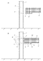
先ずPCa柱1は、図1に示すように、基礎コンクリートG上に立設され、その梁接合位置には梁上端主筋挿入用の第一貫通孔2及び梁下端主筋挿入用の第二貫通孔3が水平方向に設けられている。また、PCa梁4には、上端主筋を持たないあばら筋4aの上部が露出する構成とされている。つまり工場やサイト等で半打ち状態として形成している。PCa柱1との接合端部には下底面部にハンチ状段部5を設け、前記ハンチ状段部5の軸方向に後述する梁下端主筋8(図3参照)を貫通させる主筋通し孔6を設けている。
Hereinafter, an embodiment of a method for joining precast concrete column beams according to the present invention will be described with reference to the drawings.
First, as shown in FIG. 1, the
前記主筋通し孔6は図2に示すようにシース管で形成されており、工場等でPCa梁4を成型する際にあばら筋4aの底部に配置して一体化される。本実施例では4本のシース管を使用した。図示することは省略したが前記PCa柱1の第一貫通孔2、第二貫通孔3も同径の4本のシース管を配置して一体形成される(請求項3記載の発明)。
The main bar through-
上記PCa梁4には、図3に示すように、PCa柱1との接合面端部に剪断力伝達手段7を設けている。前記剪断力伝達手段7は例えばコッターと称されるものであり、PCa梁4の接合端面部であばら筋4aの略中央部に配置されている(図2参照)。前記コッターの凹みは15〜20mm程度とされ後述するグラウト材が充填されて完成状態となり、剪断力をPCa柱1へ伝達させる構成である。剪断伝達能力をより高めるために対向するPCa柱1にも同じ高さ位置で略同形同大のコッターを設けることが好ましい。
As shown in FIG. 3, the
上記のような構成とされたPCa梁4は、前記ハンチ状段部5の主筋通し孔6とこれに対向するPCa柱1の第二貫通孔3とを一致させて、同主筋通し孔6の端部から梁下端主筋8を差し入れて通し、PCa柱1の第二貫通孔3を横断し、他方に同様の構成で配置されているPCa梁4の主筋通し孔6へ通す。
The
次に、梁上端主筋9をPCa梁4の上面に露出したあばら筋4a内に配筋し、PCa柱1の第一貫通孔2に差し入れて通し、他方に同様の構成で配置されているPCa梁4のあばら筋4a内に配筋して挿通させる。その後、矢印Aに示すように、PCa柱1の第一貫通孔2の一側又は両側からグラウト材を充填する。また、矢印Bに示すように、PCa梁4の主筋通し孔6の一側又は両側からグラウト材を充填し第二貫通孔3にも及ばせる。またその際、前記剪断力伝達手段7にもグラウト材が注入されて剪断力伝達手段7が完成される。
Next, the beam upper
しかる後に、PCa梁4の上面に配筋された梁上端主筋9へ、床配筋を施した上で後打ちコンクリート13(床コンクリートとも云う)を打設してPCa柱梁を一体的に接合する。
本発明のプレキャストコンクリート造柱梁の接合方法は、図1又は図3に示すようにPCa柱1が複数層の高さ或いは建物高さに形成されており、PCa梁4、4をPCa柱1の梁接合箇所へ順に接合する。したがって、1層毎に柱を鉛直方向に建物高さまで連結するという面倒な作業が低減され、作業効率が飛躍的に向上できる。
After that, floor reinforcement is applied to the beam upper
In the method for joining precast concrete column beams of the present invention, as shown in FIG. 1 or FIG. 3, the
上記の如く接合された柱梁間の応力伝達は、変形時においてPCa柱1から梁下端主筋8に加わる応力を梁下端主筋8の直上に配置されているPCa梁4内の下端主筋4bへ伝達させる事によって行われる。
The stress transmission between the columns and beams joined as described above transmits the stress applied from the
因みに応力伝達能力は、ハンチ状段部5の軸方向の長さと比例しているため、高い応力伝達力が求められる場合にはハンチ状段部5を軸方向に長くすればよい。しかし、施工上ハンチ状段部5を極力短くして部材の取り合いを小さくすることが好ましい。そのため、図4に示すように梁下端主筋8の両端部に定着具11を取り付けて定着することが好適に実施される(請求項4記載の発明)。前記定着具11は例えばネジ材である。これは抜け止め程度のものでありプレストレスを加えるものではない。前記定着具11はPCa梁4の内方に向かって力が加えられるためその上面に配筋されている梁4の下端主筋4bへ応力が伝達されやすいのである。
Incidentally, since the stress transmission capability is proportional to the axial length of the hunch-
次に、請求項2に記載したプレキャストコンクリート造柱梁の接合方法について実施例3として説明する。本実施例も実施例1及び2と略同様の技術的思想に基づいており、以下、図面に基づいて説明する。
PCa柱10の梁接合箇所には、図5に示すように、梁上端主筋挿入用の第一貫通孔20を設け、同第一貫通孔20より下方位置に梁受け用のブラケット10a(顎)を柱と一体的に設けている。また、柱10は前記ブラケット10aとPCa柱1を水平方向に貫通する梁下端主筋挿入用の第二貫通孔30を設けている。
Next, a method for joining precast concrete column beams described in
As shown in FIG. 5, a first through
PCa梁40には、実施例1と同様に上端主筋を持たないあばら筋40aの上部が露出する構成とされている。PCa柱10との接合端面部には前記ブラケット10aを梁成内に収める切り欠き部40cが形成されている。また、その下底面部にはハンチ状段部50を設け、同ハンチ状段部50の軸方向に後述する梁下端主筋80(図6参照)を貫通させる主筋通し孔60を設けている。
As in the first embodiment, the
上記の構成とされたPCa梁40は、図6に示すように、前記切り欠き部40cをこれに対向する前記PCa柱10のブラケット10aと嵌め合わせ、PCa梁40のハンチ状段部50の主筋通し孔60をPCa柱10の第二貫通孔30と一致させる。因みに、実施例1と同様に柱10のブラケット10aの上面部と切り欠き部40cの上面部とが接触される位置に前記剪断力伝達手段70を取り付けても良い(図5、図6参照)。
As shown in FIG. 6, the
そして、梁下端主筋80を前記ハンチ状段部50の主筋通し孔60の一端から差し入れPCa柱10の第二貫通孔30を横断し、他方に同様の構成で配置されているPCa梁40の主筋通し孔60へ差し入れて挿通する。また、梁上端主筋90はPCa梁40上面のあばら筋40a内に配筋し、PCa柱10の第一貫通孔20に差し入れて通し、他方に同様の構成で配置されているPCa梁40のあばら筋40a内に配筋して通す。
Then, the beam lower
しかる後に、図3と同様にPCa柱10の第一貫通孔20、PCa梁40の主筋通し孔60及びPCa柱10の第二貫通孔30内へグラウト材をそれぞれ充填し、梁上端主筋90へ後打ちコンクリート130を打設してPCa柱梁を接合する。グラウト材の充填、後打ちコンクリート130の打設は上述したとおりである。
Thereafter, similar to FIG. 3, the grout material is filled into the first through
また、図示することは省略したが、図4と同様に梁下端主筋80の両端に定着具11を取り付け定着してハンチ状段部50を軸方向に短くすることも好適に実施される。
Although not shown in the figure, it is also preferable that the fixing
上述した実施例は建物の中央部に配置される直交梁を接続する柱の場合について説明したが、本発明は建物の外周部位に配置される柱においても実施できる。以下のその点を図7A、図7Bに基づいて説明する。また、実施例1〜4の技術的思想と略同様であるためその相違点を中心に説明する。 Although the above-described embodiment has been described with respect to a column connecting orthogonal beams arranged in the center of a building, the present invention can also be implemented in a column arranged in an outer peripheral portion of a building. The following points will be described with reference to FIGS. 7A and 7B. Moreover, since it is substantially the same as the technical idea of Examples 1-4, it demonstrates centering on the difference.
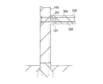
図7Aに示す建物の外周部位に立設されたPCa柱1’には、第一貫通孔2’と第二貫通孔3’とが水平方向に設けられている。前記第一貫通孔2’と、第二貫通孔3’はそれぞれ、外壁面側の端部が幅広に形成されている。そして、図7Bに示すように、PCa柱1’との接合端面部に剪断力伝達手段7’を設けた上で、実施例1と同様に構成されたハンチ状段部5’の主筋通し孔6’とPCa柱1’の第二貫通孔3’とを一致させて梁下端主筋8’を前記ハンチ状段部5’の主筋通し孔6’の一端から差し入れ、PCa柱1’の第二貫通孔3’を横断して通す。その後、前記第二貫通孔3’の外壁面側に形成された幅広の空間において、挿通された梁下端主筋8’の端部を定着具11’により固定する。前記定着具11’は上述したネジ材である。梁上端主筋9’も上述の如くあばら筋4a’内に配筋させ、第一貫通孔2’へ差し入れて通し、その端部を定着具11’により固定する。その後、第一貫通孔2’、第二貫通孔3’の外壁面側(矢印C)からグラウト材を充填させ、梁上面の梁上端主筋9’へ後打ちコンクリート13’を打設して柱梁を接合する。
A first through
また、梁下端主筋8’の建物側の端部にも定着具12を取り付けてハンチ状段部5’の軸方向の長さを短くすることも好適に実施される。更に、図5、6及び実施例3、4で記載したブラケットを設ける接合方法も同様に実施できる。
In addition, it is also preferable that the fixing
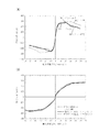
次に、実施例1、実施例2、実施例4に記載したプレキャストコンクリート造柱梁の接合方法の実用性を知るため、柱と梁を一体打ちしたときと、柱と梁を別々に作成した後両者を一体化したとき(実施例1、2、4と同様の方法)の強度と剛性を比較するべく十字型試験体による加力実験を実施した。つまり、試験体の柱には梁主筋用の貫通孔を設け、大梁の下底面部には下端主筋を後から挿入するハンチ状段部と主筋通し孔を設け、プレキャスト柱と大梁を仮設後にこれらの孔に主筋を配筋し、グラウト材等の充填をすることで柱梁接合した十字型試験体により実験した。その結果を図8に示す。 Next, in order to know the practicality of the joining method of the precast concrete column beam described in Example 1, Example 2, and Example 4, the column and the beam were separately created when the column and the beam were integrally hit. Then, a force test using a cross-shaped specimen was performed to compare the strength and rigidity when both were integrated (the same method as in Examples 1, 2, and 4). In other words, the column of the specimen is provided with a through hole for the main beam of the beam, the bottom bottom part of the main beam is provided with a hunch-like step part into which the lower main bar is inserted later, and the main bar through hole. An experiment was conducted using a cross-shaped specimen in which main bars were placed in the holes of the rods and filled with a grout material or the like. The result is shown in FIG.
図8Aに示すように、一体打ちしたもの(PH1)と、実施例1、2、4の柱梁をプレキャストとして後から一体化したもの(PH2〜PH4)の梁部材の強度は略同等である。また、図8Bに示すように、一体打ちしたもの(PH1)と、柱梁をプレキャストとして後から一体化したもの(PH2〜PH4)の梁部材の剛性も略同様である。
つまり、本発明のプレキャストコンクリート造柱梁の接合方法は一体打ちした構造とほぼ同様の構造性能を示すことが分かる。したがって、実施例1、2、4に記載した簡易な方法での柱梁の接合方法を実施しても強度、剛性等の構造性能に全く影響を及ぼさず積極的に実施できるのである。この結果は勿論他の実施例の実用性をも示すものである。
As shown in FIG. 8A, the strength of the beam member of the one that is integrally hit (PH1) and the one that is integrated later after pre-casting the column beams of Examples 1, 2, and 4 (PH2 to PH4) are substantially equal. . Further, as shown in FIG. 8B, the rigidity of the beam members of the one that is integrally hit (PH1) and the one that is integrated later after pre-casting the column beam (PH2 to PH4) are substantially the same.
In other words, it can be seen that the method for joining precast concrete column beams of the present invention exhibits substantially the same structural performance as that of a united structure. Therefore, even if the column beam joining method by the simple method described in the first, second, and fourth embodiments is performed, it can be carried out positively without affecting the structural performance such as strength and rigidity. This result naturally shows the practicality of other embodiments.
以上に実施形態を図面に基づいて説明したが、本発明は、図示例の実施形態の限りではなく、その技術的思想を逸脱しない範囲において、当業者が通常に行う設計変更、応用のバリエーションの範囲を含むことを念のために付言する The embodiments have been described with reference to the drawings. However, the present invention is not limited to the illustrated embodiments, and design modifications and application variations that are usually made by those skilled in the art are within the scope of the technical idea of the invention. Add a note to include the scope
1、1’、10 柱
2、2’、20 第一貫通孔
3、3’、30 第二貫通孔
4、4’、40 梁
4a、4a’、40a あばら筋
5、5’、50 ハンチ状段部
6、6’、60 主筋通し孔
7、7’、70 剪断力伝達手段
8、8’、80 梁下端主筋
9、9’、90 梁上端主筋
1, 1 ', 10
Claims (6)
プレキャストコンクリート造柱の梁接合位置に梁上端主筋挿入用の第一貫通孔及び梁下端主筋挿入用の第二貫通孔をそれぞれ水平方向に設け、
プレキャストコンクリート造梁は、上端主筋を持たないあばら筋の上部を露出させ、プレキャストコンクリート造柱との接合端部の下底面部にハンチ状段部を設け、前記ハンチ状段部の梁軸方向に梁下端主筋を貫通させる主筋通し孔を設けた構成とし、
前記プレキャストコンクリート造梁におけるプレキャストコンクリート造柱との接合端面部に剪断力伝達手段を設け、
前記プレキャストコンクリート造梁は、ハンチ状段部の主筋通し孔をプレキャストコンクリート造柱の第二貫通孔と一致させて同主筋通し孔と第二貫通孔へ梁下端主筋を通し、同主筋通し孔と第二貫通孔へグラウト材を注入して固めること、
及び梁上端主筋を前記あばら筋内へ配筋した上でプレキャストコンクリート造柱の第一貫通孔へ通し、同第一貫通孔中へもグラウト材を注入して固めることによって相対峙するプレキャストコンクリート造柱とプレキャストコンクリート造梁との連結を行い、
前記せん断力伝達手段へもグラウト材を充填し固めて剪断力伝達手段を完成し、
しかる後に、プレキャストコンクリート造梁の上面のあばら筋及び梁上端主筋へ後打ちコンクリートを打設して前記プレキャストコンクリート造柱とプレキャストコンクリート造梁とを一体化することを特徴とする、プレキャストコンクリート造柱梁の接合方法。 In a method of joining a precast concrete beam to a precast concrete column,
A first through hole for inserting the beam upper main bar and a second through hole for inserting the beam lower main bar are provided in the horizontal direction at the beam joint position of the precast concrete column, respectively.
The precast concrete beam exposes the upper part of the stirrup that does not have the top main bar, and provides a haunch-like step on the bottom surface of the joint end with the precast concrete column, in the beam axis direction of the haunch-like step The main bar through hole that penetrates the beam lower bar main bar is provided,
A shearing force transmitting means is provided at a joint end surface portion with the precast concrete column in the precast concrete beam,
In the precast concrete beam, the main bar through hole of the haunch-shaped step portion is made to coincide with the second through hole of the precast concrete column, and the lower main bar of the beam is passed through the main bar through hole and the second through hole. to solidify by injecting grout into the second through hole,
And beams the upper main reinforcement through the first through hole of the precast concrete Concrete Columns on that Haisuji into the rib in muscle, Precast Concrete which faced each other by solidifying by injecting grout even in the same first through hole in Connect the columns and precast concrete beams,
The shear force transmitting means is filled with grout material and hardened to complete the shear force transmitting means.
After that, the precast concrete column is characterized in that the precast concrete column and the precast concrete beam are integrated by placing post-cast concrete on the stirrup on the upper surface of the precast concrete beam and the main upper end of the beam. Beam joining method.
プレキャストコンクリート造柱の梁接合位置に梁上端主筋挿入用の第一貫通孔を設け、同第一貫通孔より下方位置に梁受け用のブラケットを設け、同ブラケット及びプレキャストコンクリート造柱を水平方向に貫通する梁下端主筋挿入用の第二貫通孔を設け、
プレキャストコンクリート造梁は、上端主筋を持たないあばら筋の上部を露出させ、プレキャストコンクリート造柱との接合端面部に前記ブラケットをプレキャストコンクリート造梁の梁成内に収める切り欠き部を形成すると共に、梁下底面部にハンチ状段部を設け、同ハンチ状段部の梁軸方向に梁下端主筋を貫通させる主筋通し孔を設けた構成とし、
前記プレキャストコンクリート造梁は、切り欠き部をプレキャストコンクリート造柱のブラケットへ嵌め合わせ、ハンチ状段部の主筋通し孔をプレキャストコンクリート造柱の第二貫通孔と一致させ、同主筋通し孔と第二貫通孔へ梁下端主筋を通し、同主筋通し孔と第二貫通孔へグラウト材を注入して固めること、
及び梁上端主筋を前記あばら筋内へ配筋して、同梁上端主筋をプレキャストコンクリート造柱の第一貫通孔へ通し、同第一貫通孔へもグラウト材を注入して固めることによって相対峙するプレキャストコンクリート造柱とプレキャストコンクリート造梁との連結を行い、
しかる後に、プレキャストコンクリート造梁の上面のあばら筋及び梁上端主筋へ後打ちコンクリートを打設して前記プレキャストコンクリート造柱とプレキャストコンクリート造梁とを一体化することを特徴とする、プレキャストコンクリート造柱梁の接合方法。 In a method of joining a precast concrete beam to a precast concrete column,
A first through hole for inserting the beam upper main bar is provided at the beam joint position of the precast concrete column, a bracket for receiving the beam is provided below the first through hole, and the bracket and the precast concrete column are placed horizontally. Provide a second through-hole for inserting the bottom main beam of the beam to penetrate,
The precast concrete beam exposes the upper part of the stirrup that does not have the top main bar, and forms a notch that fits the bracket in the beam structure of the precast concrete beam at the joint end surface with the precast concrete column, A configuration in which a hunch-like step portion is provided on the bottom surface of the beam, and a main bar through-hole that penetrates the beam bottom main reinforcement in the beam axis direction of the hunch-like step portion is provided,
In the precast concrete beam, the notch is fitted to the bracket of the precast concrete column, the main reinforcement through hole of the hunch-shaped step portion is aligned with the second through hole of the precast concrete column, Passing the beam bottom main bar through the through hole, injecting and hardening grout material into the main bar through hole and the second through hole ,
And by Haisuji the beam upper main reinforcement to the rib in muscle, the same beam upper main reinforcement through the first through hole of the precast concrete Concrete Columns, opposed phase by solidifying by injecting grout even in the same first through hole Connecting the precast concrete pillars to the precast concrete beams,
After that, the precast concrete column is characterized in that the precast concrete column and the precast concrete beam are integrated by placing post-cast concrete on the stirrup on the upper surface of the precast concrete beam and the main upper end of the beam. Beam joining method.
Priority Applications (1)
| Application Number | Priority Date | Filing Date | Title |
|---|---|---|---|
| JP2005281868A JP5236152B2 (en) | 2005-09-28 | 2005-09-28 | Method of joining precast concrete column beams |
Applications Claiming Priority (1)
| Application Number | Priority Date | Filing Date | Title |
|---|---|---|---|
| JP2005281868A JP5236152B2 (en) | 2005-09-28 | 2005-09-28 | Method of joining precast concrete column beams |
Publications (2)
| Publication Number | Publication Date |
|---|---|
| JP2007092354A JP2007092354A (en) | 2007-04-12 |
| JP5236152B2 true JP5236152B2 (en) | 2013-07-17 |
Family
ID=37978380
Family Applications (1)
| Application Number | Title | Priority Date | Filing Date |
|---|---|---|---|
| JP2005281868A Active JP5236152B2 (en) | 2005-09-28 | 2005-09-28 | Method of joining precast concrete column beams |
Country Status (1)
| Country | Link |
|---|---|
| JP (1) | JP5236152B2 (en) |
Families Citing this family (8)
| Publication number | Priority date | Publication date | Assignee | Title |
|---|---|---|---|---|
| JP5154962B2 (en) * | 2008-02-01 | 2013-02-27 | 株式会社竹中工務店 | Precast concrete structural member joint structure, building, and construction method of building |
| JP5638878B2 (en) * | 2010-08-26 | 2014-12-10 | 株式会社竹中工務店 | Precast concrete member joint structure, structure |
| JP6792926B2 (en) * | 2016-07-21 | 2020-12-02 | 株式会社安藤・間 | Joint structure of precast concrete beam members |
| CN106522365A (en) * | 2016-11-21 | 2017-03-22 | 中建八局第四建设有限公司 | Concrete pouring method for joint of transverse beam and vertical column and separation tool |
| CN107653985B (en) * | 2017-10-21 | 2019-05-07 | 山东建筑大学 | A kind of assembled abnormity column connected node and its installation method |
| JP7314467B2 (en) * | 2019-07-25 | 2023-07-26 | 株式会社竹中工務店 | Column-beam connection structure |
| JP2021021211A (en) * | 2019-07-25 | 2021-02-18 | 清水建設株式会社 | Beam structure and structural skeleton for building |
| CN114562023A (en) * | 2022-04-21 | 2022-05-31 | 西南科技大学 | Assembly type frame connecting node, assembly type frame and assembly method |
Family Cites Families (5)
| Publication number | Priority date | Publication date | Assignee | Title |
|---|---|---|---|---|
| JP2538166B2 (en) * | 1992-08-13 | 1996-09-25 | 株式会社ピー・エス | Precast concrete flat beam and its construction method |
| JPH06212800A (en) * | 1993-01-20 | 1994-08-02 | Taisei Corp | Pressure jointing method for column and beam |
| JPH09105173A (en) * | 1995-10-09 | 1997-04-22 | Ando Corp | Connecting section structure of precast prestressed reinforced-concrete frame |
| JP2000291134A (en) * | 1999-04-01 | 2000-10-17 | Shimizu Corp | Joint structure of precast member |
| JP3527718B2 (en) * | 2001-07-02 | 2004-05-17 | 黒沢建設株式会社 | Prestressed concrete structure |
-
2005
- 2005-09-28 JP JP2005281868A patent/JP5236152B2/en active Active
Also Published As
| Publication number | Publication date |
|---|---|
| JP2007092354A (en) | 2007-04-12 |
Similar Documents
| Publication | Publication Date | Title |
|---|---|---|
| JP5236152B2 (en) | Method of joining precast concrete column beams | |
| KR101136926B1 (en) | Composite beam by prestressed concrete filled tube | |
| JP5946041B2 (en) | Column beam connection structure, column beam connection method, and precast concrete stigma member | |
| JP3900344B2 (en) | Column-to-pile connection structure of steel structure building and its construction method | |
| JP4423644B2 (en) | Hollow precast pillar | |
| JP6647721B1 (en) | Tensionless PC steel bar concrete beam-column structure | |
| JP2009281066A (en) | Building structure using composite structural beam having pc structure on its ends | |
| JP5035984B2 (en) | Joint structure of precast floor slab and beam | |
| JP2008266910A (en) | Projection structure of anchorage or deviator of tendon, and construction method therefor | |
| JP2009114755A (en) | Joint structure of precast concrete column member, and method for joining precast concrete column members | |
| JP2009002101A (en) | Method and structure for joining precast-concrete construction beam-column | |
| JP2008144431A (en) | Method and structure for joining precast reinforced concrete beam members | |
| JP2011149265A (en) | Beam member and building structure | |
| JP2010084503A (en) | Structure and method for joining concrete column and steel-frame beam | |
| JP5658966B2 (en) | Composite beam, composite beam joint structure, and composite beam joint method | |
| JP2007191865A (en) | Structure for jointing prestressed precast concrete member and member to be jointed, and prestressed precast concrete member | |
| JP2007291636A (en) | Mixed-structure beam | |
| JP2009155851A (en) | Connecting structure of precast floor slab and beam | |
| JP2007211450A (en) | Structure for joining precast column and steel-frame beam together | |
| JP4439938B2 (en) | Wall type reinforced concrete structure and its construction method | |
| KR100442704B1 (en) | Method and structure for reinforcement of ferroconcrete construction by using of exterior tension member | |
| JP3378933B2 (en) | Connection method between column and precast concrete beam | |
| JP4045502B2 (en) | Structure | |
| JP2006169837A (en) | Column-beam joint structure of reinforced concrete construction | |
| JP3844480B2 (en) | Construction method for beam-to-column joints of precast concrete columns with X-type reinforcements |
Legal Events
| Date | Code | Title | Description |
|---|---|---|---|
| A621 | Written request for application examination |
Free format text: JAPANESE INTERMEDIATE CODE: A621 Effective date: 20080626 |
|
| A977 | Report on retrieval |
Free format text: JAPANESE INTERMEDIATE CODE: A971007 Effective date: 20101119 |
|
| A131 | Notification of reasons for refusal |
Free format text: JAPANESE INTERMEDIATE CODE: A131 Effective date: 20101207 |
|
| A521 | Written amendment |
Free format text: JAPANESE INTERMEDIATE CODE: A523 Effective date: 20110204 |
|
| A02 | Decision of refusal |
Free format text: JAPANESE INTERMEDIATE CODE: A02 Effective date: 20110426 |
|
| A521 | Written amendment |
Free format text: JAPANESE INTERMEDIATE CODE: A523 Effective date: 20110725 |
|
| A521 | Written amendment |
Free format text: JAPANESE INTERMEDIATE CODE: A821 Effective date: 20110725 |
|
| A911 | Transfer of reconsideration by examiner before appeal (zenchi) |
Free format text: JAPANESE INTERMEDIATE CODE: A911 Effective date: 20110929 |
|
| A912 | Removal of reconsideration by examiner before appeal (zenchi) |
Free format text: JAPANESE INTERMEDIATE CODE: A912 Effective date: 20111028 |
|
| A521 | Written amendment |
Free format text: JAPANESE INTERMEDIATE CODE: A523 Effective date: 20120829 |
|
| A521 | Written amendment |
Free format text: JAPANESE INTERMEDIATE CODE: A821 Effective date: 20120829 |
|
| A61 | First payment of annual fees (during grant procedure) |
Free format text: JAPANESE INTERMEDIATE CODE: A61 Effective date: 20130327 |
|
| R150 | Certificate of patent or registration of utility model |
Free format text: JAPANESE INTERMEDIATE CODE: R150 Ref document number: 5236152 Country of ref document: JP Free format text: JAPANESE INTERMEDIATE CODE: R150 |
|
| FPAY | Renewal fee payment (event date is renewal date of database) |
Free format text: PAYMENT UNTIL: 20160405 Year of fee payment: 3 |