JP5220038B2 - Method of incorporating a falsification preventing device into a multi-walled container and a multi-walled container incorporating the falsification preventing device - Google Patents
Method of incorporating a falsification preventing device into a multi-walled container and a multi-walled container incorporating the falsification preventing device Download PDFInfo
- Publication number
- JP5220038B2 JP5220038B2 JP2009554717A JP2009554717A JP5220038B2 JP 5220038 B2 JP5220038 B2 JP 5220038B2 JP 2009554717 A JP2009554717 A JP 2009554717A JP 2009554717 A JP2009554717 A JP 2009554717A JP 5220038 B2 JP5220038 B2 JP 5220038B2
- Authority
- JP
- Japan
- Prior art keywords
- wall
- container
- tamper
- walled container
- walled
- Prior art date
- Legal status (The legal status is an assumption and is not a legal conclusion. Google has not performed a legal analysis and makes no representation as to the accuracy of the status listed.)
- Active
Links
- 238000000034 method Methods 0.000 title description 19
- 239000000203 mixture Substances 0.000 claims description 24
- 238000000465 moulding Methods 0.000 claims description 15
- 239000011888 foil Substances 0.000 claims description 14
- 239000000463 material Substances 0.000 claims description 9
- 229910052751 metal Inorganic materials 0.000 claims description 7
- 239000002184 metal Substances 0.000 claims description 7
- 238000003860 storage Methods 0.000 claims description 4
- 239000000758 substrate Substances 0.000 claims description 2
- 239000002274 desiccant Substances 0.000 description 13
- 239000004033 plastic Substances 0.000 description 9
- 229920003023 plastic Polymers 0.000 description 9
- 239000000853 adhesive Substances 0.000 description 7
- 230000001070 adhesive effect Effects 0.000 description 7
- 238000005516 engineering process Methods 0.000 description 7
- 238000004519 manufacturing process Methods 0.000 description 7
- -1 polyethylene Polymers 0.000 description 7
- 238000002347 injection Methods 0.000 description 6
- 239000007924 injection Substances 0.000 description 6
- 229920000642 polymer Polymers 0.000 description 6
- 239000000047 product Substances 0.000 description 6
- 239000000976 ink Substances 0.000 description 5
- 238000001746 injection moulding Methods 0.000 description 4
- 239000004698 Polyethylene Substances 0.000 description 3
- 239000004743 Polypropylene Substances 0.000 description 3
- 229920005601 base polymer Polymers 0.000 description 3
- 238000005520 cutting process Methods 0.000 description 3
- 229920000573 polyethylene Polymers 0.000 description 3
- 229920001155 polypropylene Polymers 0.000 description 3
- 229920005992 thermoplastic resin Polymers 0.000 description 3
- VTYYLEPIZMXCLO-UHFFFAOYSA-L Calcium carbonate Chemical compound [Ca+2].[O-]C([O-])=O VTYYLEPIZMXCLO-UHFFFAOYSA-L 0.000 description 2
- 230000015572 biosynthetic process Effects 0.000 description 2
- 238000007599 discharging Methods 0.000 description 2
- 229920006254 polymer film Polymers 0.000 description 2
- 230000002265 prevention Effects 0.000 description 2
- 230000008569 process Effects 0.000 description 2
- 230000004044 response Effects 0.000 description 2
- 230000000007 visual effect Effects 0.000 description 2
- 238000003466 welding Methods 0.000 description 2
- VGGSQFUCUMXWEO-UHFFFAOYSA-N Ethene Chemical compound C=C VGGSQFUCUMXWEO-UHFFFAOYSA-N 0.000 description 1
- 239000004793 Polystyrene Substances 0.000 description 1
- 229920001328 Polyvinylidene chloride Polymers 0.000 description 1
- VYPSYNLAJGMNEJ-UHFFFAOYSA-N Silicium dioxide Chemical compound O=[Si]=O VYPSYNLAJGMNEJ-UHFFFAOYSA-N 0.000 description 1
- XUIMIQQOPSSXEZ-UHFFFAOYSA-N Silicon Chemical compound [Si] XUIMIQQOPSSXEZ-UHFFFAOYSA-N 0.000 description 1
- 229910052782 aluminium Inorganic materials 0.000 description 1
- XAGFODPZIPBFFR-UHFFFAOYSA-N aluminium Chemical compound [Al] XAGFODPZIPBFFR-UHFFFAOYSA-N 0.000 description 1
- 230000004888 barrier function Effects 0.000 description 1
- 230000005540 biological transmission Effects 0.000 description 1
- 229910000019 calcium carbonate Inorganic materials 0.000 description 1
- 239000012876 carrier material Substances 0.000 description 1
- 230000008859 change Effects 0.000 description 1
- 230000005465 channeling Effects 0.000 description 1
- 239000003795 chemical substances by application Substances 0.000 description 1
- 239000004927 clay Substances 0.000 description 1
- 150000001875 compounds Chemical class 0.000 description 1
- 239000004020 conductor Substances 0.000 description 1
- 238000007796 conventional method Methods 0.000 description 1
- 239000012502 diagnostic product Substances 0.000 description 1
- GUJOJGAPFQRJSV-UHFFFAOYSA-N dialuminum;dioxosilane;oxygen(2-);hydrate Chemical compound O.[O-2].[O-2].[O-2].[Al+3].[Al+3].O=[Si]=O.O=[Si]=O.O=[Si]=O.O=[Si]=O GUJOJGAPFQRJSV-UHFFFAOYSA-N 0.000 description 1
- 238000009826 distribution Methods 0.000 description 1
- 239000003814 drug Substances 0.000 description 1
- 229920001903 high density polyethylene Polymers 0.000 description 1
- 239000004700 high-density polyethylene Substances 0.000 description 1
- 230000006698 induction Effects 0.000 description 1
- 229920000092 linear low density polyethylene Polymers 0.000 description 1
- 239000004707 linear low-density polyethylene Substances 0.000 description 1
- 229920001684 low density polyethylene Polymers 0.000 description 1
- 239000004702 low-density polyethylene Substances 0.000 description 1
- 238000012986 modification Methods 0.000 description 1
- 230000004048 modification Effects 0.000 description 1
- 239000002808 molecular sieve Substances 0.000 description 1
- 229920001748 polybutylene Polymers 0.000 description 1
- 239000004417 polycarbonate Substances 0.000 description 1
- 229920000515 polycarbonate Polymers 0.000 description 1
- 229920000728 polyester Polymers 0.000 description 1
- 229920001444 polymaleic acid Polymers 0.000 description 1
- 229920000098 polyolefin Polymers 0.000 description 1
- 229920002223 polystyrene Polymers 0.000 description 1
- 239000005033 polyvinylidene chloride Substances 0.000 description 1
- 238000002360 preparation method Methods 0.000 description 1
- 229920005989 resin Polymers 0.000 description 1
- 239000011347 resin Substances 0.000 description 1
- 239000000741 silica gel Substances 0.000 description 1
- 229910002027 silica gel Inorganic materials 0.000 description 1
- 229910052710 silicon Inorganic materials 0.000 description 1
- 239000010703 silicon Substances 0.000 description 1
- URGAHOPLAPQHLN-UHFFFAOYSA-N sodium aluminosilicate Chemical compound [Na+].[Al+3].[O-][Si]([O-])=O.[O-][Si]([O-])=O URGAHOPLAPQHLN-UHFFFAOYSA-N 0.000 description 1
- KKEYFWRCBNTPAC-UHFFFAOYSA-L terephthalate(2-) Chemical compound [O-]C(=O)C1=CC=C(C([O-])=O)C=C1 KKEYFWRCBNTPAC-UHFFFAOYSA-L 0.000 description 1
- 239000012815 thermoplastic material Substances 0.000 description 1
Images


Classifications
-
- B—PERFORMING OPERATIONS; TRANSPORTING
- B29—WORKING OF PLASTICS; WORKING OF SUBSTANCES IN A PLASTIC STATE IN GENERAL
- B29C—SHAPING OR JOINING OF PLASTICS; SHAPING OF MATERIAL IN A PLASTIC STATE, NOT OTHERWISE PROVIDED FOR; AFTER-TREATMENT OF THE SHAPED PRODUCTS, e.g. REPAIRING
- B29C45/00—Injection moulding, i.e. forcing the required volume of moulding material through a nozzle into a closed mould; Apparatus therefor
- B29C45/16—Making multilayered or multicoloured articles
- B29C45/1671—Making multilayered or multicoloured articles with an insert
-
- B—PERFORMING OPERATIONS; TRANSPORTING
- B29—WORKING OF PLASTICS; WORKING OF SUBSTANCES IN A PLASTIC STATE IN GENERAL
- B29C—SHAPING OR JOINING OF PLASTICS; SHAPING OF MATERIAL IN A PLASTIC STATE, NOT OTHERWISE PROVIDED FOR; AFTER-TREATMENT OF THE SHAPED PRODUCTS, e.g. REPAIRING
- B29C45/00—Injection moulding, i.e. forcing the required volume of moulding material through a nozzle into a closed mould; Apparatus therefor
- B29C45/14—Injection moulding, i.e. forcing the required volume of moulding material through a nozzle into a closed mould; Apparatus therefor incorporating preformed parts or layers, e.g. injection moulding around inserts or for coating articles
- B29C45/14467—Joining articles or parts of a single article
- B29C45/14491—Injecting material between coaxial articles, e.g. between a core and an outside sleeve for making a roll
-
- B—PERFORMING OPERATIONS; TRANSPORTING
- B29—WORKING OF PLASTICS; WORKING OF SUBSTANCES IN A PLASTIC STATE IN GENERAL
- B29C—SHAPING OR JOINING OF PLASTICS; SHAPING OF MATERIAL IN A PLASTIC STATE, NOT OTHERWISE PROVIDED FOR; AFTER-TREATMENT OF THE SHAPED PRODUCTS, e.g. REPAIRING
- B29C45/00—Injection moulding, i.e. forcing the required volume of moulding material through a nozzle into a closed mould; Apparatus therefor
- B29C45/14—Injection moulding, i.e. forcing the required volume of moulding material through a nozzle into a closed mould; Apparatus therefor incorporating preformed parts or layers, e.g. injection moulding around inserts or for coating articles
- B29C45/14598—Coating tubular articles
- B29C45/14614—Joining tubular articles
-
- B—PERFORMING OPERATIONS; TRANSPORTING
- B65—CONVEYING; PACKING; STORING; HANDLING THIN OR FILAMENTARY MATERIAL
- B65D—CONTAINERS FOR STORAGE OR TRANSPORT OF ARTICLES OR MATERIALS, e.g. BAGS, BARRELS, BOTTLES, BOXES, CANS, CARTONS, CRATES, DRUMS, JARS, TANKS, HOPPERS, FORWARDING CONTAINERS; ACCESSORIES, CLOSURES, OR FITTINGS THEREFOR; PACKAGING ELEMENTS; PACKAGES
- B65D1/00—Containers having bodies formed in one piece, e.g. by casting metallic material, by moulding plastics, by blowing vitreous material, by throwing ceramic material, by moulding pulped fibrous material, by deep-drawing operations performed on sheet material
- B65D1/22—Boxes or like containers with side walls of substantial depth for enclosing contents
- B65D1/26—Thin-walled containers, e.g. formed by deep-drawing operations
- B65D1/28—Thin-walled containers, e.g. formed by deep-drawing operations formed of laminated material
-
- B—PERFORMING OPERATIONS; TRANSPORTING
- B65—CONVEYING; PACKING; STORING; HANDLING THIN OR FILAMENTARY MATERIAL
- B65D—CONTAINERS FOR STORAGE OR TRANSPORT OF ARTICLES OR MATERIALS, e.g. BAGS, BARRELS, BOTTLES, BOXES, CANS, CARTONS, CRATES, DRUMS, JARS, TANKS, HOPPERS, FORWARDING CONTAINERS; ACCESSORIES, CLOSURES, OR FITTINGS THEREFOR; PACKAGING ELEMENTS; PACKAGES
- B65D81/00—Containers, packaging elements, or packages, for contents presenting particular transport or storage problems, or adapted to be used for non-packaging purposes after removal of contents
- B65D81/24—Adaptations for preventing deterioration or decay of contents; Applications to the container or packaging material of food preservatives, fungicides, pesticides or animal repellants
- B65D81/26—Adaptations for preventing deterioration or decay of contents; Applications to the container or packaging material of food preservatives, fungicides, pesticides or animal repellants with provision for draining away, or absorbing, or removing by ventilation, fluids, e.g. exuded by contents; Applications of corrosion inhibitors or desiccators
- B65D81/266—Adaptations for preventing deterioration or decay of contents; Applications to the container or packaging material of food preservatives, fungicides, pesticides or animal repellants with provision for draining away, or absorbing, or removing by ventilation, fluids, e.g. exuded by contents; Applications of corrosion inhibitors or desiccators for absorbing gases, e.g. oxygen absorbers or desiccants
-
- B—PERFORMING OPERATIONS; TRANSPORTING
- B29—WORKING OF PLASTICS; WORKING OF SUBSTANCES IN A PLASTIC STATE IN GENERAL
- B29C—SHAPING OR JOINING OF PLASTICS; SHAPING OF MATERIAL IN A PLASTIC STATE, NOT OTHERWISE PROVIDED FOR; AFTER-TREATMENT OF THE SHAPED PRODUCTS, e.g. REPAIRING
- B29C45/00—Injection moulding, i.e. forcing the required volume of moulding material through a nozzle into a closed mould; Apparatus therefor
- B29C45/14—Injection moulding, i.e. forcing the required volume of moulding material through a nozzle into a closed mould; Apparatus therefor incorporating preformed parts or layers, e.g. injection moulding around inserts or for coating articles
- B29C45/1418—Injection moulding, i.e. forcing the required volume of moulding material through a nozzle into a closed mould; Apparatus therefor incorporating preformed parts or layers, e.g. injection moulding around inserts or for coating articles the inserts being deformed or preformed, e.g. by the injection pressure
- B29C2045/14237—Injection moulding, i.e. forcing the required volume of moulding material through a nozzle into a closed mould; Apparatus therefor incorporating preformed parts or layers, e.g. injection moulding around inserts or for coating articles the inserts being deformed or preformed, e.g. by the injection pressure the inserts being deformed or preformed outside the mould or mould cavity
- B29C2045/14245—Injection moulding, i.e. forcing the required volume of moulding material through a nozzle into a closed mould; Apparatus therefor incorporating preformed parts or layers, e.g. injection moulding around inserts or for coating articles the inserts being deformed or preformed, e.g. by the injection pressure the inserts being deformed or preformed outside the mould or mould cavity using deforming or preforming means outside the mould cavity
-
- B—PERFORMING OPERATIONS; TRANSPORTING
- B29—WORKING OF PLASTICS; WORKING OF SUBSTANCES IN A PLASTIC STATE IN GENERAL
- B29C—SHAPING OR JOINING OF PLASTICS; SHAPING OF MATERIAL IN A PLASTIC STATE, NOT OTHERWISE PROVIDED FOR; AFTER-TREATMENT OF THE SHAPED PRODUCTS, e.g. REPAIRING
- B29C45/00—Injection moulding, i.e. forcing the required volume of moulding material through a nozzle into a closed mould; Apparatus therefor
- B29C45/14—Injection moulding, i.e. forcing the required volume of moulding material through a nozzle into a closed mould; Apparatus therefor incorporating preformed parts or layers, e.g. injection moulding around inserts or for coating articles
- B29C2045/14852—Injection moulding, i.e. forcing the required volume of moulding material through a nozzle into a closed mould; Apparatus therefor incorporating preformed parts or layers, e.g. injection moulding around inserts or for coating articles incorporating articles with a data carrier, e.g. chips
-
- B—PERFORMING OPERATIONS; TRANSPORTING
- B29—WORKING OF PLASTICS; WORKING OF SUBSTANCES IN A PLASTIC STATE IN GENERAL
- B29C—SHAPING OR JOINING OF PLASTICS; SHAPING OF MATERIAL IN A PLASTIC STATE, NOT OTHERWISE PROVIDED FOR; AFTER-TREATMENT OF THE SHAPED PRODUCTS, e.g. REPAIRING
- B29C45/00—Injection moulding, i.e. forcing the required volume of moulding material through a nozzle into a closed mould; Apparatus therefor
- B29C45/16—Making multilayered or multicoloured articles
- B29C45/1671—Making multilayered or multicoloured articles with an insert
- B29C2045/1673—Making multilayered or multicoloured articles with an insert injecting the first layer, then feeding the insert, then injecting the second layer
-
- B—PERFORMING OPERATIONS; TRANSPORTING
- B29—WORKING OF PLASTICS; WORKING OF SUBSTANCES IN A PLASTIC STATE IN GENERAL
- B29C—SHAPING OR JOINING OF PLASTICS; SHAPING OF MATERIAL IN A PLASTIC STATE, NOT OTHERWISE PROVIDED FOR; AFTER-TREATMENT OF THE SHAPED PRODUCTS, e.g. REPAIRING
- B29C45/00—Injection moulding, i.e. forcing the required volume of moulding material through a nozzle into a closed mould; Apparatus therefor
- B29C45/14—Injection moulding, i.e. forcing the required volume of moulding material through a nozzle into a closed mould; Apparatus therefor incorporating preformed parts or layers, e.g. injection moulding around inserts or for coating articles
- B29C45/1418—Injection moulding, i.e. forcing the required volume of moulding material through a nozzle into a closed mould; Apparatus therefor incorporating preformed parts or layers, e.g. injection moulding around inserts or for coating articles the inserts being deformed or preformed, e.g. by the injection pressure
-
- B—PERFORMING OPERATIONS; TRANSPORTING
- B29—WORKING OF PLASTICS; WORKING OF SUBSTANCES IN A PLASTIC STATE IN GENERAL
- B29C—SHAPING OR JOINING OF PLASTICS; SHAPING OF MATERIAL IN A PLASTIC STATE, NOT OTHERWISE PROVIDED FOR; AFTER-TREATMENT OF THE SHAPED PRODUCTS, e.g. REPAIRING
- B29C45/00—Injection moulding, i.e. forcing the required volume of moulding material through a nozzle into a closed mould; Apparatus therefor
- B29C45/14—Injection moulding, i.e. forcing the required volume of moulding material through a nozzle into a closed mould; Apparatus therefor incorporating preformed parts or layers, e.g. injection moulding around inserts or for coating articles
- B29C45/14467—Joining articles or parts of a single article
-
- B—PERFORMING OPERATIONS; TRANSPORTING
- B29—WORKING OF PLASTICS; WORKING OF SUBSTANCES IN A PLASTIC STATE IN GENERAL
- B29L—INDEXING SCHEME ASSOCIATED WITH SUBCLASS B29C, RELATING TO PARTICULAR ARTICLES
- B29L2031/00—Other particular articles
- B29L2031/34—Electrical apparatus, e.g. sparking plugs or parts thereof
- B29L2031/3456—Antennas, e.g. radomes
-
- B—PERFORMING OPERATIONS; TRANSPORTING
- B29—WORKING OF PLASTICS; WORKING OF SUBSTANCES IN A PLASTIC STATE IN GENERAL
- B29L—INDEXING SCHEME ASSOCIATED WITH SUBCLASS B29C, RELATING TO PARTICULAR ARTICLES
- B29L2031/00—Other particular articles
- B29L2031/712—Containers; Packaging elements or accessories, Packages
-
- B—PERFORMING OPERATIONS; TRANSPORTING
- B65—CONVEYING; PACKING; STORING; HANDLING THIN OR FILAMENTARY MATERIAL
- B65D—CONTAINERS FOR STORAGE OR TRANSPORT OF ARTICLES OR MATERIALS, e.g. BAGS, BARRELS, BOTTLES, BOXES, CANS, CARTONS, CRATES, DRUMS, JARS, TANKS, HOPPERS, FORWARDING CONTAINERS; ACCESSORIES, CLOSURES, OR FITTINGS THEREFOR; PACKAGING ELEMENTS; PACKAGES
- B65D2203/00—Decoration means, markings, information elements, contents indicators
- B65D2203/10—Transponders
-
- Y—GENERAL TAGGING OF NEW TECHNOLOGICAL DEVELOPMENTS; GENERAL TAGGING OF CROSS-SECTIONAL TECHNOLOGIES SPANNING OVER SEVERAL SECTIONS OF THE IPC; TECHNICAL SUBJECTS COVERED BY FORMER USPC CROSS-REFERENCE ART COLLECTIONS [XRACs] AND DIGESTS
- Y10—TECHNICAL SUBJECTS COVERED BY FORMER USPC
- Y10T—TECHNICAL SUBJECTS COVERED BY FORMER US CLASSIFICATION
- Y10T428/00—Stock material or miscellaneous articles
- Y10T428/13—Hollow or container type article [e.g., tube, vase, etc.]
- Y10T428/1352—Polymer or resin containing [i.e., natural or synthetic]
Description
本発明は、2007年3月19日付で提出された米国特許仮出願番号第60/895,639号の優先権及び請求項の利益を主張するものである。
本発明の技術は、多重壁型容器内への改竄防止装置の組み込み法に関し、詳しくは、多重壁型容器の製造プロセス中における当該容器への改竄防止装置の組み込み法及び、当該改竄防止装置を組み込んだ多重壁型容器に関する。
The present invention claims the priority and claims of US Provisional Application No. 60 / 895,639, filed March 19, 2007.
The technology of the present invention relates to a method for incorporating a falsification preventing device into a multi-walled container, and more specifically, a method for incorporating a falsification preventing device into the container during the manufacturing process of the multi-walled container, and the falsification preventing device. The present invention relates to an incorporated multi-walled container.
高価値型コンシューマープロダクツを模倣・偽造から守る需要が高まっている。製品の製造から小売りに至るサプライチェーンを保証させる方法の1つはサプライチェーンを通して製品を認証することである。模倣・偽造は大抵、卸しや流通の各段階で行われる。貨物追跡法では個品レベルの識別が要求される。
製薬業界が行っている認証の一例にはe−pedigreeがある。e−pedigreeは製造時から販売時までの間、薬品に付帯する電子記録である。各ユニットパッケージには認証を容易化する単数あるいは複数の無線周波数識別装置(RFID)を貼付し得る。RFIDはユニットパッケージの各々における情報の読み書き手段を提供する。サプライチェーンがRFIDテクノロジーを使えるようにするために必要なハードウェアやソフトウェアのインフラストラクチャーは高コストで且つ敷居が高く、RFID認証テクノロジー普及の大きな障壁となっている。
読み取り性のみを提供するバーコードや2Dバーコード等のもっと安価なその他の識別テクノロジーも存在する。そうした装置は一般にもっと低コストでインフラストラクチャの敷居も低いが、代表的にはバーコードはパッケージの外側に配置したものを読み取るため、ずっと模倣・偽造されやすい。
There is an increasing demand for protecting high-value consumer products from counterfeiting and counterfeiting. One way to ensure the supply chain from product manufacture to retail is to authenticate the product through the supply chain. Imitation / counterfeiting is usually done at each stage of wholesale and distribution. The cargo tracking law requires identification at the individual item level.
One example of authentication performed by the pharmaceutical industry is e-pedigree. The e-pedigree is an electronic record attached to a medicine from the time of manufacture to the time of sale. Each unit package may have one or more radio frequency identification devices (RFIDs) that facilitate authentication. RFID provides a means for reading and writing information in each of the unit packages. The hardware and software infrastructure required to enable the supply chain to use RFID technology is expensive and has a high threshold, which is a major barrier to the spread of RFID authentication technology.
There are other cheaper identification technologies such as barcodes and 2D barcodes that only provide readability. Such devices are generally cheaper and have a lower infrastructure threshold, but typically barcodes are read on the outside of the package and are much easier to imitate and counterfeit.
(1)信頼性があり、(2)不正開封防止機能(tamper evident)を有し、(3)シームレスに一体パッケージ化できる、非ビジュアル的認証法に対する需要を満たすことである。 (1) To meet the demand for a non-visual authentication method that is reliable, (2) has a tamper-evident function, and (3) can be seamlessly packaged together.
本発明の1様相によれば、多重壁型容器内に改竄防止装置を組み込む方法が提供される。多重壁型容器は、外側表面を持つ内壁と、この内壁の外側表面に隣り合う外壁とを有し、その製造中に、内壁と外壁との間に挟持させるようにして改竄防止装置が組み込まれる。 According to one aspect of the present invention, a method is provided for incorporating an anti-tamper device into a multi-walled container. The multi-walled container has an inner wall having an outer surface and an outer wall adjacent to the outer surface of the inner wall, and the tamper-proof device is incorporated so as to be sandwiched between the inner wall and the outer wall during the manufacture. .
本発明の1実施例において多重壁型容器が、ポリメリック組成物を射出成型して容器の内壁を形成することにより作製される。内壁の成型後又は成型中の何れかにおいて、内壁の外側表面に改竄防止装置を被着させる。次いで、改竄防止装置を被着させた内壁を外壁用の型キャビティ内に配置して内壁に沿って外壁をオーバーモールドし、かくして、内壁と外壁との間に改竄防止装置を挟持させた多重壁型容器を形成する。 In one embodiment of the invention, a multi-walled container is made by injection molding the polymeric composition to form the inner wall of the container. Either after or during molding of the inner wall, a tamper-proof device is attached to the outer surface of the inner wall. Next, the inner wall to which the tamper-proof device is attached is placed in the mold cavity for the outer wall, the outer wall is overmolded along the inner wall, and thus the multi-wall with the tamper-proof device sandwiched between the inner wall and the outer wall A mold container is formed.
本発明の他の実施例では、ポリメリック組成物をフィルム状に押し出し形成して多重壁型容器を作製する。フィルムは容器の内壁を形成するチューブ状構造又はスリーブ状に形成され、フィルム形成の前又は後の何れかにこのチューブ状構造内に改竄防止装置を被着させる。外壁用の型キャビティ内にチューブを配置し、チューブ状構造に沿って外壁をオーバーモールドし、かくして、内壁と外壁との間に改竄防止装置を挟持させた多重壁型容器を形成する。 In another embodiment of the present invention, the polymeric composition is extruded into a film to produce a multi-walled container. The film is formed into a tube-like structure or a sleeve shape that forms the inner wall of the container, and a tamper-proof device is attached to the tube-like structure either before or after film formation. A tube is placed in a mold cavity for the outer wall, and the outer wall is overmolded along the tubular structure, thus forming a multi-walled container with an anti-tamper device sandwiched between the inner wall and the outer wall.
本発明の他の様相において、改竄防止装置を組み込んだ多重壁型容器が提供される。多重壁型容器で使用するに好適な種々の改竄防止装置には、RFID、印刷アンテナ又は箔アンテナ、導電性インク、メタル球、X線読み取り可能な箔、が含まれる。改竄防止装置は多重壁型容器の各壁又は各層間に位置付けられるので容易には改竄できない。 In another aspect of the present invention, a multi-walled container incorporating an anti-tamper device is provided. Various anti-tamper devices suitable for use with multi-walled containers include RFID, printed or foil antennas, conductive inks, metal spheres, and X-ray readable foils. Since the tamper-proof device is positioned between each wall or each layer of the multi-walled container, it cannot be easily tampered with.
(1)信頼性があり、(2)不正開封防止機能(tamper evident)を有し、(3)シームレスにパッケージとして一体化できる、非ビジュアル的認証法に対する需要を満たす、多重壁型容器内への改竄防止装置の組み込み法及び当該改竄防止装置を組み込んだ多重壁型容器が提供される。 (1) Reliable, (2) Tamper Evidence (Tamp Evidence), (3) Seamlessly integrated into a package that meets the demand for non-visual authentication methods into multi-walled containers A method for assembling the tamper-proof device and a multi-walled container incorporating the tamper-proof device are provided.
以下に、多重壁型又は多重層型の容器(以下、単に容器とも称する)に改竄防止装置を組み込む方法を説明する。これらの容器は熱可塑性樹脂で作製され、調剤、医療用の各装置、医療診断用の各製品で使用できる。本発明によれば、改竄防止装置は容器製造プロセス中に容器の1つ以上の壁又は層の間に挿通して位置付けられる。 Hereinafter, a method of incorporating the falsification preventing device into a multi-wall type or multi-layer type container (hereinafter also simply referred to as a container) will be described. These containers are made of a thermoplastic resin and can be used in preparations, medical devices, and medical diagnostic products. In accordance with the present invention, the anti-tamper device is positioned through one or more walls or layers of the container during the container manufacturing process.
改竄防止装置は、容器の壁間に配置されると色々の検知テクノロジーを使用する非接触様式下に“質問”(interrogation)される。そうしたテクノロジーには、これに限定しないが、(1)RFID、(2)IR、(3)導電性、(4)誘導、(5)マイクロウェーブ、等がある。
容器の直近に配置したリーダーが改竄防止装置に“質問”する。装置のタイプに応じた情報が読み取られ、装置に書き込まれる。
多重壁型容器は、保存スペースを画定する外壁を含み、この保存スペースには単数又は複数の物品が保存され得る。外壁は熱可塑性樹脂から構成されるが、この外壁を形成するための好適な熱可塑性樹脂には、ポリエチレン、ポリプロピレン、ポリビニリデンクロリド、ポリエチレンビニルアセテート、ポリスチレン、ポリカーボネート、ポリエステルテレフタレート、ポリブチレン、メタロセン触媒ポリオレフィン、ポリマレイン酸、が含まれる。好ましい樹脂はポリプロピレンとポリエチレンである。外壁は好ましくは0.5〜2.0mm、より好ましくは0.6〜1.0mmの厚さを有する。
When placed between container walls, the anti-tamper device is “interrogated” in a non-contact manner using various sensing technologies. Such technologies include, but are not limited to, (1) RFID, (2) IR, (3) conductivity, (4) induction, (5) microwave, and the like.
A leader placed in the immediate vicinity of the container “questions” the anti-tamper device. Information according to the type of device is read and written to the device.
A multi-walled container includes an outer wall that defines a storage space in which one or more articles can be stored. The outer wall is composed of a thermoplastic resin, and suitable thermoplastic resins for forming the outer wall include polyethylene, polypropylene, polyvinylidene chloride, polyethylene vinyl acetate, polystyrene, polycarbonate, polyester terephthalate, polybutylene, metallocene-catalyzed polyolefin. , Polymaleic acid. Preferred resins are polypropylene and polyethylene. The outer wall preferably has a thickness of 0.5 to 2.0 mm, more preferably 0.6 to 1.0 mm.
多重壁型容器は、外壁が画定する保存スペース内で且つ外壁に隣り合う内壁を有する。内壁はガスを吸収又は放出する活性ポリマー組成物から作製され得る。1実施例では活性ポリマー組成物に乾燥材が組み込まれる。好適な乾燥材には、これに限定しないが、シリカゲル、モレキュラシーブ、炭酸カルシウム、及び、これに限定しないが、モンモリロナイト粘土を含む自然の粘土化合物、が含まれる。 The multi-walled container has an inner wall adjacent to the outer wall in a storage space defined by the outer wall. The inner wall can be made from an active polymer composition that absorbs or releases gas. In one embodiment, a desiccant is incorporated into the active polymer composition. Suitable desiccants include, but are not limited to, silica gel, molecular sieves, calcium carbonate, and natural clay compounds including but not limited to montmorillonite clay.
他の実施例において、乾燥材組成物には成型物の成型に使用する組成物を含む1つ以上の乾燥材プラスチック組成物が含まれる。そうした乾燥材プラスチック組成物は2相及び又は3相の組成物を含み得る。2相組成物は、乾燥材とベースポリマーとを含み、3相組成物は乾燥材と、少なくとも2つの不混和性のベースポリマーとを含む。本発明の1実施例において、乾燥材の充填量はポリマーの重量%で約10〜約80%、あるいは約30〜約70%の範囲であり得る。 In other embodiments, the desiccant composition includes one or more desiccant plastic compositions that include the composition used to mold the molding. Such desiccant plastic compositions can include two-phase and / or three-phase compositions. The two-phase composition includes a desiccant and a base polymer, and the three-phase composition includes a desiccant and at least two immiscible base polymers. In one embodiment of the invention, the desiccant loading may range from about 10 to about 80%, or from about 30 to about 70% by weight of polymer.
別の実施例ではベースポリマーを、ポリオレフィン−ポリエチレン(LDPE、LLDPE、HDPE)及びポリプロピレンを含む熱可塑性材料の群から選択したものを使用できる。好適な3相の乾燥材同伴プラスチック組成物には、これに限定しないが、米国特許第5.911,937号、同第6,214,255号、同第6,130,263号、同第6,080,350号、同第6,174,952号、同第6,124,006号、同第6,221,446号、の1つ以上に開示された乾燥材プラスチックが含まれる。これらの米国特許はここに引用することにより本明細書に含まれるものとする。乾燥材充填量及びプラスチック組成物中のチャンネリングエージェントを変更することにより、乾燥材同伴プラスチックの全体的な保水量や水分取り込み量を制御できる。
上述したような乾燥材組成物はアラバマ州AuburnのCSP Technologies社より入手できる。
In another embodiment, the base polymer can be selected from the group of thermoplastic materials including polyolefin-polyethylene (LDPE, LLDPE, HDPE) and polypropylene. Suitable three-phase desiccant entrained plastic compositions include, but are not limited to, US Pat. Nos. 5,911,937, 6,214,255, 6,130,263, The desiccant plastics disclosed in one or more of US Pat. Nos. 6,080,350, 6,174,952, 6,124,006, 6,221,446 are included. These US patents are hereby incorporated by reference herein. By changing the desiccant filling amount and the channeling agent in the plastic composition, it is possible to control the overall water retention amount and moisture uptake amount of the desiccant entrained plastic.
The desiccant composition as described above is available from CSP Technologies, Auburn, Alabama.
多重壁型容器は多様な方法で製造し得る。例えば、ある実施例ではオーバーモールド法を使用して内壁又はスリーブを射出成型する。スリーブは円筒状又は管状で、上部及び底部は開放され得る。あるいはスリーブは成型したベース部と側壁とを有し、上部のみが開放され得る。
成型したスリーブを容器型のコア上に配置し、次いでスリーブを覆って容器の外壁を形成するプラスチック材料を射出成型する。成型された容器は射出成型した内壁と、射出成型された外壁とを有する。容器は1つ以上の成型機を使用して成型できる。
Multi-walled containers can be manufactured in a variety of ways. For example, in one embodiment, the inner wall or sleeve is injection molded using an overmold method. The sleeve can be cylindrical or tubular and the top and bottom can be open. Alternatively, the sleeve can have a molded base and side walls, and only the top can be opened.
The molded sleeve is placed on a container-shaped core, and then a plastic material that covers the sleeve and forms the outer wall of the container is injection molded. The molded container has an injection molded inner wall and an injection molded outer wall. The container can be molded using one or more molding machines.
他の実施例では、フィルムスリーブ法を使用して多重壁型容器を作製する。この方法ではポリマーフィルムを押し出し成型して内壁を作製する。ポリマーフィルムは所望の容器の内側円周部と高さとに合致するサイズにダイカットされる。ポリマーフィルは約0.05〜約0.8mm、好ましくは約0.3〜約0.6mmの範囲の厚さを有し得る。カットしたフィルム片は管状に丸められ且つ相互に連結され、かくして自立チューブ(又はスリーブ)を構成する。このフィルムを、例えば接着材又は熱加締め(heat staking)法又は超音波溶接法を使用して連結し得る。スリーブは上部及び底部を共に開放した円筒形状を有する。 In another embodiment, a multi-walled container is made using the film sleeve method. In this method, a polymer film is extruded to produce an inner wall. The polymer film is die cut to a size that matches the inner circumference and height of the desired container. The polymer fill may have a thickness in the range of about 0.05 to about 0.8 mm, preferably about 0.3 to about 0.6 mm. The cut film pieces are rolled into a tube and connected to each other, thus forming a self-supporting tube (or sleeve). The films can be joined using, for example, an adhesive or a heat stacking method or an ultrasonic welding method. The sleeve has a cylindrical shape with both the top and bottom open.
フィルムスリーブを容器型のコア上に配置する。1実施例では、型コア上への配置はロボットアームを介して行う。フィルムスリーブを、例えば、吸引又は静電気印加のような、斯界に既知の従来法又は任意の方法の組み合わせにより型内に然るべく配置し、次いで型を閉じ、スリーブ上にプラスチックを射出成型して多重壁形容器の外壁を形成する。次いで型を開き、フィルムスリーブ付きの成型外壁と共に多重壁型容器を取り出す。フィルムスリーブの形成と、引き続く容器外壁の成型については、ここに引用することによりその全部が本明細書中に含まれるものとする“Method and Composition for an In−Mold Liner”と題するWO03/013843に記載される。成型した容器は押し出しフィルムから形成した内壁と、射出成型した外壁とを有する。 A film sleeve is placed on the container-shaped core. In one embodiment, placement on the mold core is via a robot arm. The film sleeve is placed in the mold accordingly by conventional methods or any combination of methods known in the art, such as suction or electrostatic application, then the mold is closed and plastic is injection molded onto the sleeve. Forms the outer wall of a multi-walled container. The mold is then opened and the multi-walled container is removed with a molded outer wall with a film sleeve. The formation of a film sleeve and subsequent molding of the outer wall of the container is described in WO 03/013843 entitled “Method and Composition for an In-Mold Liner”, which is hereby incorporated by reference in its entirety. be written. The molded container has an inner wall formed from an extruded film and an injection molded outer wall.
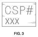
ここに開示する多重壁型容器には多様な改竄防止装置を組み込み得る。使用可能な改竄防止装置の1つには、例えば図1に例示した印刷アンテナのような印刷アンテナ又は箔形アンテナがある。この装置は、導電性インクを用いて印刷し得、又は金属箔箔、好ましくはアルミ箔をダイカットして形成し得る。あるいはアンテナは、図2及び3に夫々例示したような特定パターンを有する箔シート又は箔材料であり得る。各容器毎に独自のアンテナ形状又はパターンを使用できる。 Various tamper-proof devices can be incorporated in the multi-walled container disclosed herein. One anti-tampering device that can be used is a printed antenna such as the printed antenna illustrated in FIG. 1 or a foil antenna. This device can be printed with conductive ink or can be formed by die cutting a metal foil foil, preferably an aluminum foil. Alternatively, the antenna may be a foil sheet or foil material having a specific pattern as illustrated in FIGS. 2 and 3, respectively. A unique antenna shape or pattern can be used for each container.
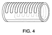
アンテナは、図4に示すように内壁の外側表面上に配置する。アンテナは内壁の外側表面上に直接印刷され得、又は、内壁の外側表面に結局は付着されるラベル上に配置され得る。アンテナは無線周波数により“質問”され得る。1実施例において、無線周波数はFM帯のものである。FM受信器又はモバイルフォンは、アンテナからの信号を送受信するために使用できる。各容器は、所定の入力信号に対して一意に反応する。更に他の実施例において、容器外壁の無線伝送特性を変更すると応答信号が変化され得る。そうした変化は、外壁のプラスチックの材料の導電特性又は厚さを変更して行い得る。 The antenna is placed on the outer surface of the inner wall as shown in FIG. The antenna can be printed directly on the outer surface of the inner wall, or can be placed on a label that will eventually be attached to the outer surface of the inner wall. The antenna can be “queried” by radio frequency. In one embodiment, the radio frequency is in the FM band. An FM receiver or mobile phone can be used to send and receive signals from the antenna. Each container responds uniquely to a given input signal. In yet another embodiment, changing the wireless transmission characteristics of the container outer wall can change the response signal. Such changes may be made by changing the conductive properties or thickness of the outer wall plastic material.
改竄防止装置の更に他の実施例では導電性インク又は金属球を使用する。導電性インクは内壁の外側表面に被着させ得るラベル上に印刷される。金属球はキャリヤ物質、例えば、内壁の外側表面にやはり被着されるラベルの如きにも被着させ得る。導電性インク又は金属球は、容器を一意に識別するパターンにまとめられる。導電性材料は金属検出器を使用して“質問”される。 Still another embodiment of the anti-tamper device uses conductive ink or metal spheres. The conductive ink is printed on a label that can be applied to the outer surface of the inner wall. The metal spheres can also be applied to a carrier material, such as a label that is also applied to the outer surface of the inner wall. The conductive ink or metal sphere is grouped into a pattern that uniquely identifies the container. The conductive material is “queried” using a metal detector.
使用可能な他の改竄防止装置は、X線読み取り可能な箔形状のものである。箔は、容器のX線画像で認識できる特定位置に、賦形され又はパターン化された、例えば孔開け模様を有する。例えば箔片に、X線画像で言葉として読み取れるように文字“VALID”をカッティングし得る。
図5に例示する他の実施例は、アンテナとシリコンチップとを含むRFIDインレーである。このインレーは代表的には連続ロールとして供給される。インレーはダイカット品、例えばダイカットラベルであり得、容器の内壁の外側表面に被着される。
Another anti-tampering device that can be used is a foil shape that can be read by X-rays. The foil has a shaped or patterned, for example perforated pattern, at a specific location that can be recognized by an X-ray image of the container. For example, the letter “VALID” can be cut on a foil piece so that it can be read as a word in an X-ray image.
Another example illustrated in FIG. 5 is an RFID inlay including an antenna and a silicon chip. This inlay is typically supplied as a continuous roll. The inlay can be a die cut product, such as a die cut label, and is applied to the outer surface of the inner wall of the container.
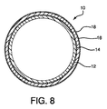
図6〜図8に例示した他の実施例では、多重壁型容器10は、外側表面にアンテナ14を接着した内壁12を有する。内壁12を覆う外壁16が成型され、かくしてアンテナ14が内壁12と外壁16との間に挟持される。次いで、容器10を充填した後、外壁16に印刷ラベルのようなラベル18を被着させる。あるいはラベル18は、外壁用の型キャビティ内に配置し、次いで外壁16を成型し、かくして製造プロセス中に外壁16に被着させ得る。印刷ラベルは、容器の内壁12に被着させたアンテナ14からの信号をキャンセルアウト又は増幅する“チューニングラベル”として作用し、かくして特定の製品タイプに対する一意の識別を提供する。チューニングラベルは、共鳴を使用して容器を1つの無線周波数に反応させる。
In other embodiments illustrated in FIGS. 6 to 8, the
図6〜図8の実施例は、作動用デバイス(アンテナ+チューニングラベル)が、容器を改竄防止装置に成型するプロセス中に組み立てられる点で、図1〜5の実施例とは異なる。図1〜図5では全ての改竄防止装置は容器内に成型される以前はスタンドアロン装置として作動するが、図6〜図8に例示する改竄防止装置は、成型プロセス中に容器内に組み込まれるまでは非機能部品として存在する。容器内に組み込まれると、アンテナとチューニングラベルとは、容器のアンテナで受信可能な特定の周波数レンジの無線波を送る別個の装置と共に動作する。容器は、その外側のラベルと共に、発信元からの無線周波数を“チューニング”するチューナーとして作用するように設計される。チューニング用の異なるラベルや、異なる肉厚の壁、異なる壁形状、等を使用することで出力信号は無限化され得る。 The embodiment of FIGS. 6-8 differs from the embodiment of FIGS. 1-5 in that the actuating device (antenna + tuning label) is assembled during the process of molding the container into an anti-tamper device. 1-5 all operate as stand-alone devices before being molded into a container, the anti-tamper devices illustrated in FIGS. 6-8 are until incorporated into the container during the molding process. Exists as a non-functional part. When incorporated in a container, the antenna and tuning label operate with a separate device that transmits radio waves of a particular frequency range that can be received by the container antenna. The container, along with its outer label, is designed to act as a tuner that “tunes” the radio frequency from the source. By using different tuning labels, different wall thicknesses, different wall shapes, etc., the output signal can be infinite.
別体の装置は、容器に関してチューニングした特定の周波数レンジの信号を送信する。容器はこの信号に応答して音波を発射し又は振動する。音波又は振動は、信号を発信した装置と同じ装置または別個のリーダー装置であり得る、改竄防止装置のリーダーによって読み取られる。外側のラベル又は容器が改竄されていると容器は発信信号に応答しない。
以下に、改竄防止装置を組み込む多重壁型容器の製造方法を説明する。
A separate device transmits a signal in a specific frequency range tuned with respect to the container. The container emits or vibrates sound waves in response to this signal. The sound waves or vibrations are read by the reader of the anti-tamper device, which can be the same device that sent the signal or a separate reader device. If the outer label or container is tampered with, the container will not respond to the outgoing signal.
Below, the manufacturing method of the multi-wall type container incorporating the tamper-proof device will be described.
1実施例において内壁は、ポリメリック組成物を閉じた型キャビティ中に射出する射出成型プロセスにより形成する。改竄防止装置は、内壁の成型の前又後の何れかにおいて、多重壁型容器中に組み込まれる。改竄防止装置を内壁成型前に組み込む場合、改竄防止装置を先ず内壁の成型キャビティ中に配置する。装置は、内壁にラベルとしてが被着するよう、内壁のポリメリック組成物と互換性のあるポリマーからなる基材を含むラベル形態のものであることが好ましい。装置は、成型した内壁の外側表面に被着するようにして型キャビティ内に配置される。 In one embodiment, the inner wall is formed by an injection molding process in which the polymeric composition is injected into a closed mold cavity. The anti-tamper device is incorporated into the multi-walled container either before or after molding the inner wall. When the anti-tamper device is incorporated before molding the inner wall, the anti-tamper device is first placed in the molding cavity of the inner wall. The device is preferably in the form of a label comprising a substrate made of a polymer compatible with the inner wall polymeric composition so that the inner wall is applied as a label. The device is placed in the mold cavity so as to adhere to the outer surface of the molded inner wall.
装置を型キャビティ内に配置したら型を閉じ、閉じた型キャビティ内に内壁のポリメリック組成物を射出して内壁を形成する。次いで型を開き、成型物を、外側表面に被着された改竄防止装置と共に取り出す。次いで、成型した内壁を、同じ成型機上の、又は別個の成型機の、外壁用の型キャビティ内に配置する。型キャビティを閉じ、この型キャビティ内に外壁用のポリメリック組成物を射出して内壁の周囲に外壁をオーバーモールドする。完成した多重壁型容器は、容器の外壁と内壁との間に挟持した改竄防止装置を有する。外側のチューニング用ラベルを容器に設けたい場合はこのラベルを、成型した容器の外壁に例えば、ラベルを容器に固定する接着材を使用して容器に被着させ得る。あるいはラベルを、成型した内壁と共に外壁用の型キャビティ内に配置し得る。次いで、外壁用のポリメリック組成物を型キャビティ内に射出し、かくして、チューニング用ラベルを被着させた外壁をオーバーモールドする。 Once the device is placed in the mold cavity, the mold is closed and the inner wall polymeric composition is injected into the closed mold cavity to form the inner wall. Next, the mold is opened, and the molded product is taken out together with an anti-tamper device attached to the outer surface. The molded inner wall is then placed in a mold cavity for the outer wall on the same molding machine or on a separate molding machine. The mold cavity is closed, and the outer wall polymeric composition is injected into the mold cavity to overmold the outer wall around the inner wall. The completed multi-walled container has a tamper-proof device sandwiched between the outer wall and the inner wall of the container. If it is desired to provide an outer tuning label on the container, this label can be applied to the outer wall of the molded container using, for example, an adhesive that secures the label to the container. Alternatively, the label can be placed in the mold cavity for the outer wall along with the molded inner wall. Next, the polymeric composition for the outer wall is injected into the mold cavity, thus overmolding the outer wall to which the tuning label is applied.
容器の内壁を成型した後で改竄防止装置を組み込みたい場合は、例えば、接着性のラベル又は、装置を内壁の外側表面に接着するその他形式の接着材を使用して装置を内壁の外側表面に被着させる。改竄防止装置は、成型機のコアから内壁を排出する前、あるいは又は、型から内壁を排出させた後(成型後)の何れかにおいて被着させる。次いで、改竄防止装置を被着した状態に成型した内壁を外壁用の型キャビティ内に配置し、先に説明したように内壁の周囲に外壁をオーバーモールドし、かくして多重壁型容器を形成する。 If you want to incorporate a tamper-proof device after molding the inner wall of the container, for example, use an adhesive label or other type of adhesive that bonds the device to the outer surface of the inner wall. Adhere. The falsification preventing device is attached either before discharging the inner wall from the core of the molding machine or after discharging the inner wall from the mold (after molding). Next, the inner wall molded with the tamper-proof device attached is placed in the mold cavity for the outer wall, and as described above, the outer wall is overmolded around the inner wall, thus forming a multi-walled container.
別の実施例では容器の内壁は、射出成型法ではなくフィルムスリーブ法で形成される。フィルムスリーブ法では、容器の内壁を形成するために使用するポリメリックフィルム中にポリメリック組成物を押し出し成型する。フィルムは、ダイカットの如きカッティングにより、内壁を形成する適宜の寸法形状とされる。カットしたフィルムを、底部及び上部を開放した管状又はスリーブ状に形成する。フィルムの各端部は、例えば接着剤、熱加締め、又は超音波溶接を使用してタブ又はスリーブ形状に固定する。あるいはフィルムは、カッティングしてチューブ状に形成するのではなくむしろ、チューブ形状にに押し出し形成し得る。この実施例では、押し出し機から続くチューブは所望の容器のサイズに合わせてカットされる。 In another embodiment, the inner wall of the container is formed by a film sleeve method rather than an injection molding method. In the film sleeve method, the polymeric composition is extruded into a polymeric film used to form the inner wall of the container. The film has an appropriate size and shape that forms the inner wall by cutting such as die cutting. The cut film is formed into a tubular or sleeve shape with the bottom and top open. Each end of the film is secured in a tab or sleeve shape using, for example, an adhesive, heat caulking, or ultrasonic welding. Alternatively, the film may be extruded into a tube shape rather than being cut into a tube. In this embodiment, the tube following the extruder is cut to the desired container size.
改竄防止装置は、フィルムをチューブ状構造に形成する前に、カッティングしたフィルムに接着され、又は、あるいは、フィルムをチューブ又はスリーブ状に形成した後にフィルムの外側表面に装置を接着させ得る。改竄防止装置は、接着性のラベル又はその他の、フィルムに改竄防止装置を接着させる接着材により、フィルムに被着される。
フィルムをチューブ又はスリーブ状に形成した後、このチューブ又はスリーブを射出成型機のコア上に配置し、型キャビティを閉じる。容器の外壁を形成するポリマー組成物を型キャビティ内に射出し、かくして、改竄防止装置を含む内壁チューブ又は内壁スリーブの周囲に外壁をオーバーモールドする。完成した多重壁型容器は容器の内外の各壁間に挟持された改竄防止装置を有する。
以上、本発明を実施例を参照して説明したが、本発明の内で種々の変更をなし得ることを理解されたい。
Tampering prevention device, before forming the film into a tube-like structure, it is adhered to the cut films, or alternatively, may be adhered the device to the outer surface of the film after forming a film tube or sleeve. The tamper-proof device is attached to the film with an adhesive label or other adhesive that adheres the tamper-proof device to the film.
After the film is formed into a tube or sleeve, the tube or sleeve is placed on the core of the injection molding machine and the mold cavity is closed. The polymer composition that forms the outer wall of the container is injected into the mold cavity, thus overmolding the outer wall around the inner wall tube or inner wall sleeve containing the anti-tamper device. The completed multi-walled container has a tamper-proof device sandwiched between the inner and outer walls of the container.
Although the present invention has been described with reference to the embodiments, it should be understood that various modifications can be made within the present invention.
10 多重壁型容器
12 内壁
14 アンテナ
16 外壁
18 ラベル
10
Claims (12)
容器の外壁にして、成型したポリメリック材料から形成され且つ物品をその内部に保存可能な保存スペースを画定する外壁と、
容器の内側スリーブにして、容器の外壁が画定する保存スペース内に設けられ、ポリメリック組成物を成型又は押し出し形成して形成され、容器の外壁に隣り合う外側表面を有する内側スリーブと、
内側スリーブの外側表面に被着した改竄防止装置にして、内側スリーブと外壁との間に挟持された改竄防止装置と、
を含み、
改竄防止装置が、ラベルと基材とを含み、基材が、容器の内側スリーブのポリメリック組成物との互換性を有するポリメリック材料からなる多重壁型容器。 A multi-walled container including a tamper-proof device,
An outer wall of the container that is formed from a molded polymeric material and defines a storage space in which articles can be stored;
An inner sleeve provided in a storage space defined by the outer wall of the container as an inner sleeve of the container, formed by molding or extruding the polymeric composition and having an outer surface adjacent to the outer wall of the container;
An anti-tamper device attached to the outer surface of the inner sleeve, and an anti-tamper device sandwiched between the inner sleeve and the outer wall;
Only including,
A multi-walled container , wherein the tamper-proof device includes a label and a base material, and the base material is made of a polymeric material that is compatible with the polymeric composition of the inner sleeve of the container.
Applications Claiming Priority (3)
| Application Number | Priority Date | Filing Date | Title |
|---|---|---|---|
| US89563907P | 2007-03-19 | 2007-03-19 | |
| US60/895,639 | 2007-03-19 | ||
| PCT/US2008/057527 WO2008116005A2 (en) | 2007-03-19 | 2008-03-19 | Method for incorporating an anti-counterfeiting device into a multi-walled container and the multi-walled container containing such device |
Publications (3)
| Publication Number | Publication Date |
|---|---|
| JP2010522126A JP2010522126A (en) | 2010-07-01 |
| JP2010522126A5 JP2010522126A5 (en) | 2011-04-28 |
| JP5220038B2 true JP5220038B2 (en) | 2013-06-26 |
Family
ID=39494980
Family Applications (1)
| Application Number | Title | Priority Date | Filing Date |
|---|---|---|---|
| JP2009554717A Active JP5220038B2 (en) | 2007-03-19 | 2008-03-19 | Method of incorporating a falsification preventing device into a multi-walled container and a multi-walled container incorporating the falsification preventing device |
Country Status (6)
| Country | Link |
|---|---|
| US (1) | US8815137B2 (en) |
| EP (1) | EP2136984B1 (en) |
| JP (1) | JP5220038B2 (en) |
| CN (1) | CN101678581A (en) |
| CA (1) | CA2680655C (en) |
| WO (1) | WO2008116005A2 (en) |
Families Citing this family (14)
| Publication number | Priority date | Publication date | Assignee | Title |
|---|---|---|---|---|
| US20090004231A1 (en) | 2007-06-30 | 2009-01-01 | Popp Shane M | Pharmaceutical dosage forms fabricated with nanomaterials for quality monitoring |
| EP2448454A1 (en) * | 2009-07-03 | 2012-05-09 | Nestec S.A. | Method for identifying capsules in a beverage producing device with magnetically-responsive identifier |
| CN102190108A (en) * | 2011-01-27 | 2011-09-21 | 上海高诚艺术包装有限公司 | Method for manufacturing wine bottle with RFID (radio frequency identification device) |
| US10441903B2 (en) | 2011-07-16 | 2019-10-15 | Cummins Filtration Ip, Inc. | Filter with electrical signature anti-counterfeiting feature |
| DE102011120862A1 (en) * | 2011-12-13 | 2013-06-13 | Felix Schoeller Supply Chain Technologies Gmbh & Co. Kg | Beverage box with integrated transponder arrangement |
| CN103383739A (en) * | 2011-12-31 | 2013-11-06 | 深圳市通产丽星股份有限公司 | Radio frequency identification chip and manufacturing method thereof |
| CN103381637B (en) * | 2011-12-31 | 2015-11-25 | 深圳市通产丽星股份有限公司 | Plastic packaging containers and plastic packaging containers preparation method |
| CN103522489B (en) * | 2012-07-06 | 2016-01-20 | 镇江新梦溪能源科技有限公司 | A kind of seamless metal plastics composite shaft sleeve compression mould |
| CN103593773A (en) * | 2013-11-20 | 2014-02-19 | 深圳市太和物联信息技术有限公司 | Product anti-fake method and system and client terminal |
| US10486350B2 (en) * | 2014-09-22 | 2019-11-26 | Ecomarks Plastics, LLC | Container and label |
| US9928348B2 (en) | 2015-12-21 | 2018-03-27 | At&T Intellectual Property I, L.P. | Medicine dispensing system |
| DE102016103488A1 (en) * | 2016-02-26 | 2017-08-31 | Inotech Kunststofftechnik Gmbh | Method for producing a multi-component injection molded part |
| DE202016004642U1 (en) * | 2016-07-28 | 2016-11-15 | Sata Gmbh & Co. Kg | Material container for a material to be sprayed |
| CN111232427A (en) * | 2020-01-21 | 2020-06-05 | 联想(北京)有限公司 | Water bottle |
Family Cites Families (16)
| Publication number | Priority date | Publication date | Assignee | Title |
|---|---|---|---|---|
| US3341644A (en) | 1959-07-29 | 1967-09-12 | Flair Plastics Corp | Process for producing plastic containers |
| US3302813A (en) | 1964-02-03 | 1967-02-07 | Owens Illinois Inc | Multi-piece containers |
| US5275277A (en) | 1992-10-28 | 1994-01-04 | Benjamin Gallegos | Novelty drinking glass |
| FR2737884B1 (en) * | 1995-08-17 | 1997-09-12 | Europlastiques Sa | PLASTIC PACKAGE PROVIDED WITH A LABEL AND AT LEAST ONE COMPONENT PROVIDED FOR SIGNALING ITS FLIGHT |
| NL1012428C2 (en) * | 1999-06-24 | 2000-12-28 | Schoeller Wavin Systems N V | Plastic holder for the transport and / or storage of goods. |
| JP4580530B2 (en) * | 2000-10-04 | 2010-11-17 | 大日本印刷株式会社 | Chemical package with non-contact data carrier |
| CA2468052A1 (en) | 2001-11-21 | 2003-06-05 | Capitol Insulated Products, Inc. | Method of incorporating a promotional item into a dual wall cup |
| JP2003263620A (en) * | 2002-03-11 | 2003-09-19 | Kobayashi Kirokushi Co Ltd | Rfid tag |
| JP4005424B2 (en) | 2002-06-27 | 2007-11-07 | 株式会社 和光製作所 | Sliding gate |
| WO2004027738A1 (en) * | 2002-08-27 | 2004-04-01 | Fp Corporation | Product information display body and product authentication method |
| DE10253567A1 (en) | 2002-11-15 | 2004-05-27 | Linpac Plastics Gmbh | Storage means, especially shell |
| JP2005263288A (en) * | 2004-03-19 | 2005-09-29 | Sekisui Plastics Co Ltd | Thermoplastic resin container with ic tag and manufacturing method for it |
| US7038587B2 (en) * | 2004-04-05 | 2006-05-02 | Sonoco Development, Inc. | Identification device for multilayer tubular structures |
| WO2006010141A2 (en) * | 2004-07-09 | 2006-01-26 | Advanced Plastics Technologies Luxembourg S.A. | Coating process and apparatus for forming coated articles |
| DE102004061633A1 (en) * | 2004-12-17 | 2006-06-29 | Lossau, Harald, Dr. | Container with transponder |
| US20110274867A1 (en) * | 2006-09-22 | 2011-11-10 | Guenter Pohlmann | Article produced by the two-component injection-moulding process |
-
2008
- 2008-03-19 EP EP08744079.8A patent/EP2136984B1/en active Active
- 2008-03-19 JP JP2009554717A patent/JP5220038B2/en active Active
- 2008-03-19 CA CA2680655A patent/CA2680655C/en active Active
- 2008-03-19 WO PCT/US2008/057527 patent/WO2008116005A2/en active Application Filing
- 2008-03-19 CN CN200880013688A patent/CN101678581A/en active Pending
-
2009
- 2009-09-17 US US12/561,941 patent/US8815137B2/en active Active
Also Published As
| Publication number | Publication date |
|---|---|
| JP2010522126A (en) | 2010-07-01 |
| EP2136984B1 (en) | 2016-08-31 |
| EP2136984A2 (en) | 2009-12-30 |
| US20100066502A1 (en) | 2010-03-18 |
| WO2008116005A3 (en) | 2008-11-06 |
| CA2680655C (en) | 2015-06-30 |
| US8815137B2 (en) | 2014-08-26 |
| WO2008116005A2 (en) | 2008-09-25 |
| CA2680655A1 (en) | 2008-09-25 |
| CN101678581A (en) | 2010-03-24 |
Similar Documents
| Publication | Publication Date | Title |
|---|---|---|
| JP5220038B2 (en) | Method of incorporating a falsification preventing device into a multi-walled container and a multi-walled container incorporating the falsification preventing device | |
| JP5265701B2 (en) | Method for forming object including radio frequency identification tag | |
| US20100052215A1 (en) | Radio Frequency Identification Device for Plastic Container and Method of Manufacture of Same | |
| US20060220868A1 (en) | Radio frequency identification tag package | |
| US20140291273A1 (en) | Environmentally friendly liquid container and method of manufacture | |
| US20070030151A1 (en) | Tracking device for polymeric packaging | |
| WO2002094560A3 (en) | Multi-layer stain and heat resistant plastic container for storing and heating food; method of making the same | |
| CA2905118A1 (en) | Passively enable a blister pack with wireless identification device | |
| MXPA06009541A (en) | Plastic packaging having embedded micro-particle taggants. | |
| JP2005321935A (en) | Ic tag incorporated cap | |
| US20090123780A1 (en) | Method Of Providing A Packaging Laminate With An Identification Code, Method Of Identifying A Package, And Package With Identification Code | |
| CN105102345A (en) | Anti-tamper method and packaging for important and valuable items | |
| US9862130B2 (en) | Flexible tube comprising an electronic component | |
| EP2144741A1 (en) | Method and apparatus for blow-molding containers with in-mold film having rfid tag fused thereto | |
| US20080105587A1 (en) | Biodegradable blister package | |
| US10810478B2 (en) | Tubular shaped tag structure | |
| JP4899518B2 (en) | Package with wireless IC tag | |
| JP2006327636A (en) | Container with ic tag, and packaging body with ic tag | |
| US8554642B2 (en) | RFID methods in the manufacture of reclosable packages | |
| EP2605978A1 (en) | Packaging | |
| US20080075955A1 (en) | Shrink sleeve label with thermo-reactive adhesive and method of making the same | |
| US20120267434A1 (en) | Body in the form of a packaging or of a molded part | |
| CN210235864U (en) | Intelligent express delivery bubble bag with chip | |
| JP4913894B2 (en) | Container with IC tag and package with IC tag | |
| JP2022131829A (en) | Manufacturing method of synthetic resin container |
Legal Events
| Date | Code | Title | Description |
|---|---|---|---|
| A521 | Request for written amendment filed |
Free format text: JAPANESE INTERMEDIATE CODE: A523 Effective date: 20100618 |
|
| A521 | Request for written amendment filed |
Free format text: JAPANESE INTERMEDIATE CODE: A523 Effective date: 20110308 |
|
| A621 | Written request for application examination |
Free format text: JAPANESE INTERMEDIATE CODE: A621 Effective date: 20110308 |
|
| A977 | Report on retrieval |
Free format text: JAPANESE INTERMEDIATE CODE: A971007 Effective date: 20120730 |
|
| A131 | Notification of reasons for refusal |
Free format text: JAPANESE INTERMEDIATE CODE: A131 Effective date: 20120814 |
|
| A521 | Request for written amendment filed |
Free format text: JAPANESE INTERMEDIATE CODE: A523 Effective date: 20121105 |
|
| TRDD | Decision of grant or rejection written | ||
| A01 | Written decision to grant a patent or to grant a registration (utility model) |
Free format text: JAPANESE INTERMEDIATE CODE: A01 Effective date: 20130205 |
|
| A61 | First payment of annual fees (during grant procedure) |
Free format text: JAPANESE INTERMEDIATE CODE: A61 Effective date: 20130305 |
|
| FPAY | Renewal fee payment (event date is renewal date of database) |
Free format text: PAYMENT UNTIL: 20160315 Year of fee payment: 3 |
|
| R150 | Certificate of patent or registration of utility model |
Ref document number: 5220038 Country of ref document: JP Free format text: JAPANESE INTERMEDIATE CODE: R150 Free format text: JAPANESE INTERMEDIATE CODE: R150 |
|
| R250 | Receipt of annual fees |
Free format text: JAPANESE INTERMEDIATE CODE: R250 |
|
| R250 | Receipt of annual fees |
Free format text: JAPANESE INTERMEDIATE CODE: R250 |
|
| R250 | Receipt of annual fees |
Free format text: JAPANESE INTERMEDIATE CODE: R250 |
|
| R250 | Receipt of annual fees |
Free format text: JAPANESE INTERMEDIATE CODE: R250 |
|
| R250 | Receipt of annual fees |
Free format text: JAPANESE INTERMEDIATE CODE: R250 |
|
| R250 | Receipt of annual fees |
Free format text: JAPANESE INTERMEDIATE CODE: R250 |
|
| R250 | Receipt of annual fees |
Free format text: JAPANESE INTERMEDIATE CODE: R250 |
|
| R250 | Receipt of annual fees |
Free format text: JAPANESE INTERMEDIATE CODE: R250 |
|
| R250 | Receipt of annual fees |
Free format text: JAPANESE INTERMEDIATE CODE: R250 |