JP5144067B2 - Game machine - Google Patents

Game machine Download PDF

Info

Publication number
JP5144067B2
JP5144067B2 JP2006343379A JP2006343379A JP5144067B2 JP 5144067 B2 JP5144067 B2 JP 5144067B2 JP 2006343379 A JP2006343379 A JP 2006343379A JP 2006343379 A JP2006343379 A JP 2006343379A JP 5144067 B2 JP5144067 B2 JP 5144067B2
Authority
JP
Japan
Prior art keywords
display
data
pressing operation
flag
effect control
Prior art date
Legal status (The legal status is an assumption and is not a legal conclusion. Google has not performed a legal analysis and makes no representation as to the accuracy of the status listed.)
Expired - Fee Related
Application number
JP2006343379A
Other languages
Japanese (ja)
Other versions
JP2008154618A (en
JP2008154618A5 (en
Inventor
和俊 中島
敏男 小倉
Current Assignee (The listed assignees may be inaccurate. Google has not performed a legal analysis and makes no representation or warranty as to the accuracy of the list.)
Sankyo Co Ltd
Original Assignee
Sankyo Co Ltd
Priority date (The priority date is an assumption and is not a legal conclusion. Google has not performed a legal analysis and makes no representation as to the accuracy of the date listed.)
Filing date
Publication date
Application filed by Sankyo Co Ltd filed Critical Sankyo Co Ltd
Priority to JP2006343379A priority Critical patent/JP5144067B2/en
Publication of JP2008154618A publication Critical patent/JP2008154618A/en
Publication of JP2008154618A5 publication Critical patent/JP2008154618A5/ja
Application granted granted Critical
Publication of JP5144067B2 publication Critical patent/JP5144067B2/en
Expired - Fee Related legal-status Critical Current
Anticipated expiration legal-status Critical

Links

Images

Description

本発明は、パチンコ遊技機、コイン遊技機、スロットマシンなどで代表される遊技機に関する。詳しくは、遊技媒体を用いて遊技者が所定の遊技を行なうことが可能である遊技機に関する。   The present invention relates to a gaming machine represented by a pachinko gaming machine, a coin gaming machine, a slot machine and the like. Specifically, the present invention relates to a gaming machine in which a player can play a predetermined game using a game medium.

この種の遊技機として従来から一般的に知られているものに、たとえば、遊技媒体を用いて遊技者が所定の遊技を行なうことが可能であるパチンコ遊技機等の遊技機がある。   Conventionally known as this type of gaming machine is, for example, a gaming machine such as a pachinko gaming machine in which a player can play a predetermined game using a gaming medium.

このような遊技機では、遊技者が操作可能な操作手段として、リーチの種類の選択、および、所定の演出の実行のように複数の事項についての指示をするために、複数の操作手段を遊技機に設置することが必要となる場合があった。そして、そのような従来の遊技機としては、複数の事項についての指示をするために、押しボタンおよび十字キー等の複数の操作手段を別体で設けたものがあった(特許文献1)。
特開2006−55311号公報(図1、図4、段落番号0017,0021)
In such a gaming machine, as the operation means that can be operated by the player, a plurality of operation means are used in order to give instructions regarding a plurality of items such as selection of a reach type and execution of a predetermined effect. In some cases, it was necessary to install the machine. As such a conventional gaming machine, there is one in which a plurality of operation means such as a push button and a cross key are separately provided in order to instruct a plurality of matters (Patent Document 1).
JP 2006-55311 A (FIG. 1, FIG. 4, paragraph numbers 0017, 0021)

しかし、前述した従来の遊技機においては、操作手段を別体で設ける構成であったために、操作手段を設置するために広範囲の設置領域を確保する必要があるという問題があった。   However, since the conventional gaming machine described above has a configuration in which the operation means is provided separately, there is a problem that it is necessary to secure a wide installation area in order to install the operation means.

本発明は、かかる事情に鑑み考え出されたものであり、その目的は、複数の操作手段を設置するための領域を省スペース化することができる遊技機を提供することである。   The present invention has been devised in view of such circumstances, and an object of the present invention is to provide a gaming machine capable of saving an area for installing a plurality of operation means.

課題を解決するための手段の具体例およびその効果Specific examples of means for solving the problems and their effects

(1) 遊技媒体(遊技球)を用いて遊技者が所定の遊技を行なうことが可能である遊技機(パチンコ遊技機1)であって、
所定の演出を行なう演出表示装置(変動表示装置9)と、
該演出表示装置の制御を行なう演出制御手段(演出制御用マイクロコンピュータ100)と、
遊技者により操作可能な操作手段(操作部81)とを備え、
該操作手段は、
予め定められた複数の方向(前後左右の4方向)へ遊技者が押圧操作可能な押圧操作部材(押圧操作部811)と、
前記予め定められた複数の方向のそれぞれに対応して設けられ、対応する方向への前記押圧操作部材による押圧操作を検出する複数の押圧操作検出手段(第1押圧検出器81a、第2押圧検出器81b、第3押圧検出器81c、第4押圧検出器81d)と、
該複数の押圧操作検出手段のうち1つの押圧操作検出手段により前記押圧操作が検出されたときに、当該押圧操作検出手段が検出した押圧操作の方向を特定可能な押圧操作検出信号(1つの押圧検出器から出力される検出信号)を前記演出制御手段へ出力する押圧操作検出信号出力手段(第1押圧検出器81a、第2押圧検出器81b、第3押圧検出器81c、第4押圧検出器81dのうちいずれか1つの検出器、および、入力IC620)とを含み、
前記演出制御手段は、
所定の遊技条件が成立していないときにおいて遊技者が前記押圧操作部材を押圧操作したときには、当該押圧操作に対応する押圧操作検出信号に基づいて、複数種類の表示動作のうち当該押圧操作検出信号により特定される押圧操作の操作方向に対応した表示動作をする第1の表示(図24の(b),(c)のキャラクタ選択画像の表示)を前記演出表示装置において行なう表示制御をする第1表示制御手段(図46のS671,S672、図55のS765,S768)と、
前記所定の遊技条件(スーパーリーチの演出表示をする条件)が成立したときにおいて遊技者が前記押圧操作部材を押圧操作したときには、当該押圧操作に対応する押圧操作検出信号に基づいて、当該押圧操作の操作方向にかかわらず、前記第1の表示とは異なる表示動作をする第2の表示(図22の(g)のパワーを貯める表示)を前記演出表示装置において行なう表示制御をする第2表示制御手段(図46のS671〜S674、図55のS759,S761)とを含む。
(1) A gaming machine (pachinko gaming machine 1) in which a player can perform a predetermined game using a game medium (game ball),
An effect display device (variation display device 9) for performing a predetermined effect;
Production control means (production control microcomputer 100) for controlling the production display device;
Operating means (operation part 81) that can be operated by the player,
The operation means includes
A pressing operation member (pressing operation unit 811) capable of being pressed by a player in a plurality of predetermined directions (four directions including front, rear, left and right);
A plurality of pressing operation detection means (first pressing detector 81a, second pressing detection) provided corresponding to each of the plurality of predetermined directions and detecting a pressing operation by the pressing operation member in the corresponding direction. 81b, third press detector 81c, fourth press detector 81d),
When the pressing operation is detected by one pressing operation detecting unit among the plurality of pressing operation detecting units, a pressing operation detection signal (one pressing operation) that can specify the direction of the pressing operation detected by the pressing operation detecting unit. Press operation detection signal output means (first press detector 81a, second press detector 81b, third press detector 81c, fourth press detector) for outputting detection signal output from the detector to the effect control means. Any one of the detectors 81d and the input IC 620),
The production control means includes
When a player presses the pressing operation member when a predetermined gaming condition is not established, the pressing operation detection signal among a plurality of types of display operations is based on a pressing operation detection signal corresponding to the pressing operation. Display control for performing the first display (display of the character selection image of (b) and (c) of FIG. 24) on the effect display device for performing the display operation corresponding to the operation direction of the pressing operation specified by 1 display control means (S671, S672 in FIG. 46, S765, S768 in FIG. 55),
When a player at the time when the said predetermined game condition (condition for the effect display of super reach) is satisfied has pressed the pressing member, on the basis of the pressing operation detection signal corresponding to the pressing operation, those pressing Regardless of the operation direction of the pressure operation, display control is performed in which the second display that performs a display operation different from the first display (the display that stores the power of FIG. 22G) is performed in the effect display device. 2 display control means (S671 to S674 in FIG. 46, S759 and S761 in FIG. 55).

このような構成によれば、予め定められた複数の方向へ押圧操作可能な押圧操作部材が操作部材として設けられ、所定の遊技条件が成立していないときにおいて1つの押圧操作検出手段により押圧操作が検出されたときに、押圧操作の操作方向に対応した表示動作をする第1の表示が行なわれ、所定の遊技条件が成立したときにおいて、押圧操作が検出されたときに、当該押圧操作検出信号により特定される押圧操作の操作方向にかかわらず、第1の表示とは異なる表示動作をする第2の表示が行なわれる。これにより、1つの操作部材を操作することに基づいて、異なる表示動作を行なうことができるので、操作部材を多機能化することができる。このような多機能化により、操作手段における操作部材数の増加を防ぐことができるので、操作手段の設置領域を省スペース化することができる。さらにこのような多機能化により、操作手段の操作に応じて行なわれる表示動作が多様化するので、遊技としての面白みを向上させることができる。さらに、所定の遊技条件が成立したときにおいては、押圧操作の操作方向にかかわらず、押圧操作が検出されたときに第2の表示が行なわれるので、操作手段の操作性を向上させることができる。 According to such a configuration, the pressing operation member that can be pressed in a plurality of predetermined directions is provided as the operation member, and the pressing operation is detected by one pressing operation detecting means when a predetermined game condition is not satisfied. Is detected, the first display that performs a display operation corresponding to the operation direction of the pressing operation is performed, and when a predetermined gaming condition is satisfied, the pressing operation is detected when the pressing operation is detected. Regardless of the operation direction of the pressing operation specified by the signal, the second display that performs a display operation different from the first display is performed. Accordingly, since different display operations can be performed based on operating one operation member, the operation member can be multifunctional. Such multi-functionality can prevent an increase in the number of operation members in the operation means, so that the installation area of the operation means can be saved. Furthermore, such multi-functionalization diversifies the display operation performed in accordance with the operation of the operation means, so that the fun as a game can be improved. Furthermore, when a predetermined game condition is satisfied, the second display is performed when the pressing operation is detected regardless of the operating direction of the pressing operation, so that the operability of the operating means can be improved. .

(2) 前記第2表示制御手段は、予め定められたリーチ表示態様(スーパーリーチの表示態様)となったときに、前記所定の遊技条件が成立したと判断する(図55のS757)。 (2) the second table示制control means, when a predetermined reach the display mode (display mode for super reach), the predetermined game condition is judged to be satisfied (S757 in FIG. 55).

このような構成によれば、予め定められたリーチ表示態様となったときに、所定の遊技条件が成立したと判断され、押圧操作の操作方向によらず、押圧操作検出手段の押圧操作が検出されたときに第2の表示が行なわれるので、操作手段の操作性の向上に基づいて、遊技者の操作負担を軽減することができる。これにより、遊技者がリーチ表示態様での演出表示に注目しながら第2の表示のために操作手段を操作することが容易化される。   According to such a configuration, when a predetermined reach display mode is achieved, it is determined that a predetermined game condition has been established, and the pressing operation of the pressing operation detecting means is detected regardless of the operating direction of the pressing operation. When this is done, the second display is performed, so that the operational burden on the player can be reduced based on the improvement in the operability of the operating means. Thereby, it becomes easy for the player to operate the operation means for the second display while paying attention to the effect display in the reach display mode.

(3) 前記演出制御手段は、前記所定の遊技条件が成立したときにおいて、前記押圧操作部材を押圧操作することに応じて前記第2の表示が行なわれることを、前記演出表示装置に表示することにより遊技者に報知する(図22の(f))押圧操作報知手段(図54のS845B,S845F)をさらに含む。   (3) The effect control means displays on the effect display device that the second display is performed in response to the pressing operation of the pressing operation member when the predetermined game condition is satisfied. This further includes pressing operation notifying means (S845B and S845F in FIG. 54) for notifying the player (FIG. 22 (f)).

このような構成によれば、所定の遊技条件が成立したときにおいて、押圧操作部材を押圧操作することに応じて第2の表示が行なわれることが、演出表示装置に表示されることにより遊技者に報知されるので、押圧操作部材の押圧操作と、第2の表示との関係を遊技者に認識させることができ、遊技としての面白みを向上させることができる。   According to such a configuration, when a predetermined game condition is satisfied, the fact that the second display is performed in response to the pressing operation of the pressing operation member is displayed on the effect display device, so that the player Therefore, the player can recognize the relationship between the pressing operation of the pressing operation member and the second display, and the fun of the game can be improved.

(4) 前記操作手段は、
前記押圧操作部材の周りに回転可能に設けられ、遊技者が回転操作可能な回転操作部材(回転操作部812)と、
該回転操作部材による回転操作を検出する回転操作検出手段(第1回転検出器81e、第2回転検出器81f)と、
該回転操作検出手段により前記回転操作が検出されたときに、当該回転操作を特定可能な回転検出信号(図19の検出信号)を前記演出制御手段へ出力する回転検出信号出力手段(第1回転検出器81e、第2回転検出器81f、および、入力IC620)とをさらに含み、
前記演出制御手段は、入力された前記回転検出信号に基づいて、前記第1の表示および前記第2の表示とは異なる表示動作をする第3の表示(図22の(c),(d)、図23の(c),(d)の表示)を前記演出表示装置において行なう表示制御をする第3表示制御手段(図46のS675、図55のS753,S755)をさらに含む。
(4) The operation means includes:
A rotation operation member (rotation operation unit 812) that is rotatably provided around the pressing operation member and is rotatable by the player;
Rotation operation detection means (first rotation detector 81e, second rotation detector 81f) for detecting rotation operation by the rotation operation member;
When the rotation operation is detected by the rotation operation detection means, a rotation detection signal output means (first rotation) for outputting a rotation detection signal (detection signal in FIG. 19) capable of specifying the rotation operation to the effect control means. A detector 81e, a second rotation detector 81f, and an input IC 620),
Based on the input rotation detection signal, the effect control means performs a display operation different from the first display and the second display (third display (c) and (d) in FIG. 22). The third display control means (S675 in FIG. 46, S753, S755 in FIG. 55) is further included to perform display control in which the display of (c) and (d) in FIG.

このような構成によれば、押圧操作部材の周りに回転可能であり、遊技者が回転操作可能な回転操作部材が操作部材として設けられ、回転操作検出手段により前記回転操作が検出されたときに、第1の表示および第2の表示とは異なる表示動作をする第3の表示が行なわれる。これにより、押圧操作部材の周りの回転操作部材を操作することに基づいて、さらに異なる表示動作を行なうことができるので、操作手段の設置スペースを大幅に増やすことなく操作手段を多機能化することができる。そして、このような多機能化により、操作手段の操作に応じて行なわれる表示動作がさらに多様化するので、遊技としての面白みをさらに向上させることができる。   According to such a configuration, when the rotation operation member that can rotate around the pressing operation member and can be rotated by the player is provided as the operation member, and the rotation operation is detected by the rotation operation detection means, Then, a third display that performs a display operation different from the first display and the second display is performed. Thereby, since different display operations can be performed based on operating the rotary operation member around the pressing operation member, the operation means can be made multifunctional without significantly increasing the installation space for the operation means. Can do. Such multi-functionalization further diversifies the display operation performed in accordance with the operation of the operation means, so that the fun as a game can be further improved.

(5) 前記押圧操作検出信号出力手段は、前記押圧操作検出信号をシリアル信号方式で出力する(図11、図18)。 (5) The pressing operation detection signal output means outputs the pressing operation detection signal by a serial signal method (FIGS. 11 and 18).

このような構成によれば、押圧操作検出信号がシリアル信号方式で出力されるので、操作手段と演出制御手段との間の配線を簡素化することができる。 According to such a configuration, since the pressing operation detection signal is output in a serial signal system, the wiring between the operation unit and the effect control unit can be simplified.

(6) 前記操作手段は、前記複数の押圧操作検出手段のそれぞれにより前記押圧操作部材による押圧操作が検出される前記予め定められた複数の方向のそれぞれに対応して設けられた複数の発光手段(第1操作部ランプ82a、第2操作部ランプ82b、第3操作部ランプ82c、第4操作部ランプ82d)をさらに含み、
前記演出制御手段は、前記発光手段にシリアル信号方式の駆動信号を供給することにより(図11、図18)前記発光手段を駆動制御する発光制御手段(図50のS726、図55のS760,S762,S766,S769、シリアル−パラレル変換IC615)をさらに含む。
(6) The operation means includes a plurality of light emitting means provided corresponding to each of the plurality of predetermined directions in which a pressing operation by the pressing operation member is detected by each of the plurality of pressing operation detection means. (First operation unit lamp 82a, second operation unit lamp 82b, third operation unit lamp 82c, fourth operation unit lamp 82d),
The effect control means supplies the light emission means with a drive signal of a serial signal system (FIGS. 11 and 18). Light emission control means for controlling the light emission means (S726 in FIG. 50, S760, S762 in FIG. 55). , S766, S769, serial-parallel conversion IC 615).

このような構成によれば、発光手段を駆動制御する駆動信号がシリアル信号方式で発光手段に供給されるので、演出制御手段と発光手段との間の配線を簡素化することができる。   According to such a configuration, since the drive signal for driving and controlling the light emitting means is supplied to the light emitting means by a serial signal method, the wiring between the effect control means and the light emitting means can be simplified.

(7) 前記演出制御手段は、
前記押圧操作部材をいずれの方向に押圧操作するべきかを説明する操作説明表示(図21の(b)、図24の(b))を前記演出表示装置において行なう表示制御をする操作説明表示制御手段(図50のS725、図54のS845B,S845F)と、
該操作説明表示制御手段により前記演出表示装置において行なわれる前記操作説明表示に連動して、前記複数の発光手段のうちから選択した発光手段を発光させる駆動制御を行なうことにより、いずれの方向に押圧操作するべきかを示す操作案内発光動作をさせる操作案内発光制御手段(図50のS726、図55のS754,S760,S766)とをさらに含む。
(7) The production control means includes:
Operation explanation display control for performing display control in the effect display device for explaining operation explanation (FIG. 21 (b), FIG. 24 (b)) explaining in which direction the pressing operation member should be pressed. Means (S725 in FIG. 50, S845B, S845F in FIG. 54),
The operation explanation display control means is pressed in any direction by performing drive control for causing the light emitting means selected from the plurality of light emitting means to emit light in conjunction with the operation explanation display performed on the effect display device. Operation guide light emission control means (S726 in FIG. 50, S754, S760, S766 in FIG. 55) for performing an operation guide light emission operation indicating whether or not to operate is further included.

このような構成によれば、押圧操作部材をいずれの方向に押圧操作するべきかを説明する操作説明表示が演出表示装置において行なわれ、さらに、その操作説明表示に連動して、押圧操作部材による押圧操作が検出される複数の方向のそれぞれに対応して設けられた複数の発光手段のうちから選択された発光手段を発光させる操作案内発光動作が行なわれる。これにより、押圧操作部材を操作することが必要となったときに、押圧操作部材をどのように押圧操作するべきかを遊技者に確実に認識させることができる。   According to such a configuration, an operation explanation display for explaining in which direction the push operation member should be pushed is performed on the effect display device, and further, in conjunction with the operation explanation display, by the push operation member. An operation guide light emission operation is performed for causing a light emitting means selected from among a plurality of light emitting means provided corresponding to each of a plurality of directions in which a pressing operation is detected to emit light. Thereby, when it becomes necessary to operate a press operation member, a player can be made to recognize reliably how to press-operate a press operation member.

(8) 前記演出制御手段は、
前記操作手段が故障しているか否かを判定する故障判定手段(図59のS781〜785)と、
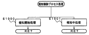
該故障判定手段による判定に基づいて、前記操作手段が故障している旨を報知する故障報知手段(図60のS1900,S1901)とをさらに含み、
前記故障判定手段は、前記押圧操作検出信号出力手段から出力される前記押圧操作検出信号について、所定期間に亘り変化がないこと(故障判定用操作検出フラグがセットされずに、操作部故障判定用カウントタイマ値が所定値以上となったこと)に基づいて、前記操作手段が故障していると判定する(図59のS784,S785)。
(8) The production control means includes:
Failure determination means (S781 to 785 in FIG. 59) for determining whether or not the operation means has failed;
A failure notifying means (S1900, S1901 in FIG. 60) for notifying that the operating means has failed based on the determination by the failure determining means;
Said failure determining means, for the pressing operation detection signal outputted from the pressing operation detection signal output means, there is no change over a predetermined time period (without being failure determination operation detection flag is set, for determining the operation unit failure Based on the fact that the count timer value is equal to or greater than a predetermined value), it is determined that the operating means has failed (S784, S785 in FIG. 59).

このような構成によれば、押圧操作検出信号について、所定期間に亘り変化がないことに基づいて、操作手段が故障していると判定され、操作手段が故障している旨が報知される。これにより、所定期間操作手段が使用されていないときに、故障している旨の報知を行なうことができる。また、自動で報知を行なうので、わざわざ故障の検査を行なう必要なく故障診断をすることができる。 According to such a configuration, it is determined that the operating means has failed based on the fact that there is no change in the pressing operation detection signal over a predetermined period, and the fact that the operating means has failed is notified. Thereby, when the operation means is not used for a predetermined period, it is possible to notify that there is a failure. In addition, since the notification is automatically performed, failure diagnosis can be performed without the need for bothering to inspect the failure.

以下、本発明の実施の形態を、図面を参照して説明する。なお、遊技機の一例としてパチンコ遊技機を示すが、本発明はパチンコ遊技機に限られず、コイン遊技機およびスロットマシン等のその他の遊技機であってもよく、遊技媒体を用いて遊技者が所定の遊技を行なうことが可能である遊技機であれば、どのような遊技機であってもよい。図4は、可動部材としてのトロッコの動作を示す説明図である。図5は、可動部材としての梁の動作を示す説明図である。
〔第1実施形態〕
まず、図1〜図5を用いて遊技機の一例であるパチンコ遊技機1の構成について説明する。図1は、図2のガラス扉枠2を取外した状態のパチンコ遊技機を正面から見た正面図である。図2はガラス扉枠2の前面を示す正面図である。図3は打球供給皿(上皿)3を拡大した平面図である。
Hereinafter, embodiments of the present invention will be described with reference to the drawings. Note that a pachinko gaming machine is shown as an example of the gaming machine, but the present invention is not limited to a pachinko gaming machine, and may be other gaming machines such as a coin gaming machine and a slot machine. Any gaming machine may be used as long as it can play a predetermined game. FIG. 4 is an explanatory view showing the operation of the truck as the movable member. FIG. 5 is an explanatory view showing the operation of the beam as the movable member.
[First Embodiment]
First, the configuration of a pachinko gaming machine 1 that is an example of a gaming machine will be described with reference to FIGS. FIG. 1 is a front view of the pachinko gaming machine with the glass door frame 2 of FIG. 2 removed as viewed from the front. FIG. 2 is a front view showing the front surface of the glass door frame 2. FIG. 3 is an enlarged plan view of the hit ball supply tray (upper plate) 3.

パチンコ遊技機1は、縦長の方形状に形成された外枠(図示せず)と、外枠の内側に開閉可能に取付けられた遊技枠11とで構成される。遊技枠11は、外枠に対して開閉自在に設置される前面枠2aと、機構部品等が取付けられる機構板(図示せず)と、それらに取付けられる種々の部品(後述する遊技盤を除く。)とを含む構造体である。前面枠2aの前面側の上部には、図2に示すような額縁状に形成されたガラス扉枠2が開閉可能に設けられている。図2に示すガラス扉枠2は、後述する遊技盤6の遊技領域7をほぼ透視し得る開口部としての円形透視窓が開設され、該円形透視窓の裏面から複層ガラス板が装着されるようになっている。図1においては、図2のようなガラス扉枠2が取外された状態のパチンコ遊技機1が示されている。   The pachinko gaming machine 1 includes an outer frame (not shown) formed in a vertically long rectangular shape, and a game frame 11 attached to the inside of the outer frame so as to be opened and closed. The game frame 11 includes a front frame 2a that can be freely opened and closed with respect to the outer frame, a mechanism plate (not shown) to which mechanism parts and the like are attached, and various parts attached to them (excluding game boards to be described later). .). A glass door frame 2 formed in a frame shape as shown in FIG. 2 is provided at the upper part on the front side of the front frame 2a so as to be opened and closed. The glass door frame 2 shown in FIG. 2 is provided with a circular see-through window as an opening through which a game area 7 of a game board 6 described later can be almost seen through, and a multilayer glass plate is mounted from the back surface of the circular see-through window. It is like that. FIG. 1 shows a pachinko gaming machine 1 with the glass door frame 2 as shown in FIG. 2 removed.

前面枠2aの前面側の下部には、ガラス扉枠2の下部に位置する態様で、打球供給皿(上皿)3が設けられている。図1において、打球供給皿3の上部に図2に示すガラス扉枠2が開閉可能に取付けられ、ガラス扉枠2が閉じられた状態で遊技が行なわれる。打球供給皿3の下部には、打球供給皿3に収容しきれない遊技球を貯留する余剰球受皿4と遊技球を発射する打球操作ハンドル(操作ノブ)5とが設けられている。   A hitting ball supply tray (upper plate) 3 is provided at a lower portion on the front side of the front frame 2a so as to be positioned below the glass door frame 2. In FIG. 1, the glass door frame 2 shown in FIG. 2 is attached to the upper part of the hitting ball supply tray 3 so as to be openable and closable, and the game is performed with the glass door frame 2 closed. Under the hitting ball supply tray 3, there are provided an extra ball receiving tray 4 for storing game balls that cannot be accommodated in the hitting ball supply tray 3 and a hitting operation handle (operation knob) 5 for firing the game balls.

前面枠2aの背面には、遊技枠11の一部を構成するプラ枠(図示せず)がある。プラ枠は、機構板を含み、機構板に電源回路(図示せず)およびスピーカ27等の部品が取付けられている。また、遊技枠11のプラ枠には、遊技枠11と遊技盤6との間の配線を中継する中継基板(図示せず)が設けられている。また、遊技枠11においては、前面枠2aの裏面側に形成される遊技盤収納枠部に収容固定される態様で、遊技盤6が着脱可能に取付けられている。遊技盤6は、それを構成する板状体と、その板状体に取付けられた種々の部品とを含む構造体である。また、遊技盤6の前面には遊技領域7が形成されている。   On the back surface of the front frame 2a, there is a plastic frame (not shown) constituting a part of the game frame 11. The plastic frame includes a mechanism plate, and components such as a power supply circuit (not shown) and a speaker 27 are attached to the mechanism plate. The plastic frame of the game frame 11 is provided with a relay board (not shown) that relays the wiring between the game frame 11 and the game board 6. Further, in the game frame 11, the game board 6 is detachably attached in such a manner that it is housed and fixed in a game board storage frame portion formed on the back side of the front frame 2a. The game board 6 is a structure including a plate-like body constituting the game board 6 and various components attached to the plate-like body. A game area 7 is formed on the front surface of the game board 6.

パチンコ遊技機1の側方には、遊技者所有の記録媒体としてのプリペイドカードを受付け、そのプリペイドカードの記録情報により特定される遊技者所有の残額(残高ともいう)の使用に基づいて貸球としての遊技球を遊技者に貸出(貸与)すための処理を行なうカード処理装置であるプリペイドカードユニット(以下、単に「カードユニット」ともいう。)が、パチンコ遊技機1に隣接して設置される(図1では図示を省略し、図9に示す)。そして、パチンコ遊技機1においては、打球供給皿3に貯留された遊技媒体である遊技球を弾発発射し、その遊技球を遊技盤6に形成された遊技領域7に打込んで、以下に説明するような所定の遊技が行なわれる。そして、遊技において遊技領域7に設けられた入賞領域へ遊技球が受入れられて入賞が生じれば、払出条件が成立し、その払出条件が成立したことに基づいて景品として、景品遊技媒体である賞球(遊技球)が払出される。   The side of the pachinko machine 1 accepts a prepaid card as a player-owned recording medium, and rents a ball based on the use of the remaining amount (also referred to as a balance) owned by the player specified by the record information of the prepaid card A prepaid card unit (hereinafter also simply referred to as a “card unit”), which is a card processing device that performs processing for lending (lending) game balls as a player, is installed adjacent to the pachinko gaming machine 1. (Not shown in FIG. 1 and shown in FIG. 9). Then, in the pachinko gaming machine 1, the game balls, which are the game media stored in the hit ball supply tray 3, are shot and fired, and the game balls are driven into the game area 7 formed on the game board 6, and A predetermined game as described is performed. When a game ball is received in a winning area provided in the gaming area 7 in the game and a winning occurs, a payout condition is established, and the prize is a prize game medium as a prize based on the establishment of the payout condition. Prize balls (game balls) are paid out.

遊技領域7の中央付近には、それぞれが演出用の飾り図柄を変動表示する複数の変動表示部を含む変動表示装置(画像表示装置)9が設けられている。変動表示装置9には、たとえば「左」、「中」、「右」の3つの変動表示部(図柄表示エリア)がある。変動表示装置9は、特別図柄表示器8による特別図柄の変動表示期間中に、装飾用(演出用)の図柄としての飾り図柄の変動表示を行なう。飾り図柄の変動表示を行なう変動表示装置9は、演出制御基板に搭載されている演出制御用マイクロコンピュータによって制御される。このような変動表示装置9は、以下に示すような所定の演出を行なう演出表示装置としてパチンコ遊技機1に設けられている。   Near the center of the game area 7, there is provided a variable display device (image display device) 9 including a plurality of variable display units each displaying a decorative design for effect. The fluctuation display device 9 includes, for example, three fluctuation display portions (symbol display areas) of “left”, “middle”, and “right”. The variation display device 9 performs a variation display of a decorative symbol as a symbol for decoration (production) during the variation display period of the special symbol by the special symbol indicator 8. The variation display device 9 for performing the variation display of the decorative design is controlled by an effect control microcomputer mounted on the effect control board. Such a fluctuation display device 9 is provided in the pachinko gaming machine 1 as an effect display device for performing a predetermined effect as described below.

変動表示装置9の下方には、各々が識別可能な複数種類の識別情報としての特別図柄を変動表示する特別図柄表示器(特別図柄表示装置)8が設けられている。この実施の形態では、特別図柄表示器8は、たとえば00〜99の数字を変動表示可能な簡易で小型の表示器(たとえば7セグメントLED)で実現されている。なお、特別図柄表示器8は、2桁の数字を表示するものに限らず、0〜9等他の桁数の数字を変動表示するように構成されていてもよい。また、変動表示装置9は、特別図柄表示器8による特別図柄の変動表示期間中に、装飾用(演出用)の図柄であって各々が識別可能な複数種類の識別情報としての飾り図柄の変動表示を行なう。   Below the variable display device 9, there is provided a special symbol display device (special symbol display device) 8 that variably displays special symbols as a plurality of types of identification information that can be identified. In this embodiment, the special symbol display 8 is realized by a simple and small display (for example, 7-segment LED) capable of variably displaying numbers of, for example, 00 to 99. Note that the special symbol display 8 is not limited to displaying a two-digit number, and may be configured to variably display other digits such as 0 to 9. In addition, the variation display device 9 is a variation of decorative symbols as a plurality of types of identification information that can be identified during the variation display period of special symbols by the special symbol indicator 8 for decoration (production). Display.

特別図柄表示器8の右側には、始動入賞口13,14に入った有効入賞球数すなわち保留記憶(始動記憶または始動入賞記憶ともいう。)数を表示する4つの表示器からなる特別図柄保留記憶表示器18が設けられている。有効始動入賞がある毎に、1つの表示器の表示色を変化させる。そして、特別図柄表示器8の変動表示が開始される毎に、1つの表示器の表示色をもとに戻す。なお、変動表示装置9の表示領域内に、保留記憶数を表示する4つの表示領域からなる特別図柄保留記憶表示領域を設けるようにしてもよい。また、この実施の形態では、保留記憶数の上限値を4とするが、上限値をより大きい値にしてもよい。さらに、上限値を、遊技状態に応じて変更可能であるようにしてもよい。   On the right side of the special symbol display 8 is a special symbol hold composed of four indicators for displaying the number of effective winning balls that have entered the start winning openings 13, 14, that is, the number of hold memories (also referred to as start memory or start prize memory). A storage indicator 18 is provided. Every time there is an effective start prize, the display color of one display is changed. Then, every time the variable display of the special symbol display 8 is started, the display color of one display is restored. In the display area of the variable display device 9, a special symbol reserved storage display area including four display areas for displaying the number of reserved memories may be provided. Further, in this embodiment, the upper limit value of the number of reserved memories is 4, but the upper limit value may be a larger value. Further, the upper limit value may be changed according to the gaming state.

変動表示装置9の下方には、第1始動入賞口13を有する入賞装置が設けられている。第1始動入賞口13に入賞した遊技球は、遊技盤6の背面に導かれ、第1始動口スイッチ13aによって検出される。   A winning device having a first start winning port 13 is provided below the variable display device 9. The game ball won in the first start winning opening 13 is guided to the back of the game board 6 and detected by the first start opening switch 13a.

また、第1始動入賞口(第1始動口)13を有する入賞装置の下方には、左右一対の可動片の動作に基づいて遊技球が入賞可能な第2始動入賞口(第2始動口)14を有する可変入賞球装置15が設けられている。第2始動入賞口14に入賞した遊技球は、遊技盤6の背面に導かれ、第2始動口スイッチ14aによって検出される。可変入賞球装置15は、ソレノイド16を励磁状態にすることによって可動片が開動作されることにより開状態とされる。可変入賞球装置15が開状態になることによって、遊技球が第2始動入賞口14に入賞可能になり(始動入賞し易くなり)、遊技者にとって有利な状態になる。可変入賞球装置15が開状態になっている状態では、第1始動入賞口13よりも、第2始動入賞口14に遊技球が入賞しやすい。また、可変入賞球装置15は、ソレノイド16を消磁状態にすることによって可動片が閉状態にされることにより閉状態とされる。可変入賞球装置15が閉状態になっている状態では、遊技球は第2始動入賞口14に入賞しない。なお、可変入賞球装置15が閉状態になっている状態において、入賞はしづらいものの、入賞することは可能である(すなわち、遊技球が入賞しにくい)ように構成されていてもよい。このような第1始動入賞口13と第2始動入賞口14とを総称して始動入賞口または始動口ということがある。   Further, below the winning device having the first starting winning opening (first starting opening) 13, a second starting winning opening (second starting opening) through which a game ball can be won based on the operation of the pair of left and right movable pieces. A variable winning ball apparatus 15 having 14 is provided. The game ball that has won the second start winning opening 14 is guided to the back of the game board 6 and detected by the second start opening switch 14a. The variable winning ball device 15 is opened when the movable piece is opened by bringing the solenoid 16 into an excited state. When the variable winning ball device 15 is in the open state, the game ball can be awarded to the second starting winning port 14 (it is easier to start winning), which is advantageous for the player. In the state where the variable winning ball apparatus 15 is in the open state, it is easier for the game ball to win the second start winning opening 14 than the first starting winning opening 13. In addition, the variable winning ball device 15 is closed when the movable piece is closed by putting the solenoid 16 in a demagnetized state. In a state where the variable winning ball device 15 is in the closed state, the game ball does not win the second start winning port 14. In the state where the variable winning ball apparatus 15 is in the closed state, it may be configured that the winning is possible (that is, it is difficult for the gaming ball to win) although it is difficult to win a prize. The first start winning port 13 and the second start winning port 14 may be collectively referred to as a start winning port or a starting port.

可変入賞球装置15が開放状態に制御されているときには、可変入賞球装置15に向かう遊技球は第2始動入賞口14に極めて入賞しやすい。そして、第1始動入賞口13は変動表示装置9の直下に設けられているが、変動表示装置9の下端と第1始動入賞口13との間の間隔をさらに狭めたり、第1始動入賞口13の周辺で釘を密に配置したり、第1始動入賞口13の周辺での釘配列を遊技球が第1始動入賞口13に導きづらくして、第2始動入賞口14の入賞率の方を第1始動入賞口13の入賞率よりもより高くするようにしてもよい。   When the variable winning ball device 15 is controlled to be in the open state, the game ball heading toward the variable winning ball device 15 is very likely to win the second start winning port 14. The first start winning opening 13 is provided immediately below the variable display device 9, but the interval between the lower end of the variable display device 9 and the first start winning opening 13 is further narrowed, or the first start winning opening is set. The nail is arranged densely around 13 or the nail arrangement around the first start winning opening 13 is difficult for the game balls to guide to the first starting winning opening 13, It is also possible to make the direction higher than the winning rate of the first start winning opening 13.

変動表示装置9の右側には、遊技演出に用いられる可動部材としてのトロッコ151が設けられている。トロッコ151は、遊技演出において、演出制御手段の制御に従って、図4に示すように、変動表示装置9の右側から左側方向に飛び出すような演出を行なうことができる。   On the right side of the variable display device 9, a truck 151 is provided as a movable member used for a game effect. In the game effect, the truck 151 can produce an effect of jumping from the right side of the variable display device 9 to the left side as shown in FIG. 4 according to the control of the effect control means.

また、変動表示装置9の上部および右側には、遊技演出に用いられる可動部材としての梁152が設けられている。梁152は、遊技演出において、演出制御手段の制御に従って、図5に示すように、変動表示装置9の上部および右側から崩れ落ちるような演出を行なうことができる。   Further, a beam 152 as a movable member used for a game effect is provided on the upper and right sides of the variable display device 9. As shown in FIG. 5, the beam 152 can perform an effect that collapses from the upper part and the right side of the variable display device 9 according to the control of the effect control means in the game effect.

さらに、変動表示装置9の下部には、特別図柄表示器8に特定表示結果(大当り図柄)が導出表示されたときに生起する遊技者にとって有利な特定遊技状態(大当り遊技状態)においてソレノイド21によって開状態とされる特別可変入賞球装置20が設けられている。特別可変入賞球装置20は、開口したときに遊技球が入賞可能となる入賞領域としての大入賞口を開閉する開閉板20aを有し、遊技者にとって有利な開放状態(開状態)と、遊技者にとって不利な閉状態とのいずれかに制御される。特定遊技状態(大当り遊技状態)においては、ソレノイド21によって特別可変入賞球装置20が開放状態に制御されることによって大入賞口が閉状態から開放状態になる。大入賞口に入賞した入賞球はカウントスイッチ23で検出される。   Further, at the lower part of the variable display device 9, a solenoid 21 is used in a specific gaming state (big hit gaming state) advantageous for a player to be generated when the specific display result (big hit symbol) is derived and displayed on the special symbol display 8. A special variable winning ball apparatus 20 that is opened is provided. The special variable winning ball apparatus 20 has an opening / closing plate 20a that opens and closes a large winning opening as a winning area in which a game ball can win when opened, and an open state (open state) advantageous to the player, and a game It is controlled to one of the closed states that is disadvantageous to the person. In the specific game state (big hit game state), the special variable winning ball apparatus 20 is controlled to be in the open state by the solenoid 21, so that the big prize opening is changed from the closed state to the open state. The winning ball that has won the big winning opening is detected by the count switch 23.

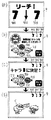
また、図3に示すように、打球供給皿3を構成する部材においては、遊技者により操作可能な操作手段としての操作部81が設けられている。操作部81は、遊技者が、遊技者から見て前後左右というような予め定められた複数の方向(4方向)のうちから選択した方向へ押圧操作をすることが可能な押しボタンスイッチ(ジョグボタン)よりなる平面視円形の押圧操作部811と、押圧操作部811の周囲で回転可能に設けられ回転操作をすることが可能なダイヤル(ジョグタイヤル)よりなる回転操作部812との複数の操作部を含む。押圧操作部811は、さらに、前後左右の4方向以外に、遊技者から見て下方向にも押圧操作可能であり、押圧操作部811において遊技者がパチンコ遊技機1に向かって前後左右4方向のうち1つの方向を選択的に押圧する方向選択操作と、方向選択操作以外に押圧操作部811全体を下方へ押圧する決定操作とを遊技者が行なうことが可能である。   In addition, as shown in FIG. 3, the member constituting the hitting ball supply tray 3 is provided with an operation portion 81 as an operation means that can be operated by the player. The operation unit 81 is a push button switch (jog switch) that allows a player to perform a pressing operation in a direction selected from a plurality of predetermined directions (four directions) such as front, rear, left, and right when viewed from the player. A plurality of operations of a pressing operation unit 811 having a circular shape in a plan view and a rotation operation unit 812 including a dial (jog tire) that can be rotated around the pressing operation unit 811 and can be rotated. Part. In addition to the four directions of front, back, left and right, the pressing operation unit 811 can also be pressed downward as viewed from the player. In the pressing operation unit 811, the player faces the pachinko gaming machine 1 in the front, rear, left, and right four directions. The player can perform a direction selection operation for selectively pressing one of the directions and a determination operation for pressing the entire pressing operation unit 811 downward in addition to the direction selection operation.

押圧操作部811において、前方向を選択する操作を行なうときに操作される部分(遊技者が押圧操作部811に向かって向こう側の部分)が、前方向部と呼ばれる。押圧操作部811において、後方向を選択する操作を行なうときに操作される部分(遊技者が押圧操作部811に向かって手前側の部分)が、後方向部と呼ばれる。押圧操作部811において、左方向を選択する操作を行なうときに操作される部分(遊技者が押圧操作部811に向かって左側の部分)が、左方向部と呼ばれる。押圧操作部811において、右方向を選択する操作を行なうときに操作される部分(遊技者が押圧操作部811に向かって右側の部分)が、右方向部と呼ばれる。   In the pressing operation unit 811, a portion operated when performing an operation of selecting the front direction (a portion on the side facing the player toward the pressing operation unit 811) is referred to as a front direction portion. In the pressing operation unit 811, a portion operated when performing an operation of selecting the backward direction (a portion on the near side of the player toward the pressing operation unit 811) is referred to as a backward direction portion. In the pressing operation portion 811, a portion operated when performing an operation of selecting the left direction (a portion on the left side of the player facing the pressing operation portion 811) is referred to as a left direction portion. In the pressing operation unit 811, a portion (a portion on the right side of the player facing the pressing operation unit 811) operated when performing an operation of selecting the right direction is referred to as a right direction unit.

また、回転操作部812は、左周りに回転する左回転操作と、右周りに回転させる右回転操作とを遊技者が任意に行なうことが可能である。   In addition, the rotation operation unit 812 allows the player to arbitrarily perform a left rotation operation that rotates counterclockwise and a right rotation operation that rotates clockwise.

また、打球供給皿3を構成する部材においては、操作部811の他に、前述のカードユニットを介して遊技球を借り受ける際に操作する球貸スイッチ91、および、プリペイドカードの返却を受けるときに操作する返却スイッチ92等の操作手段が設けられている。   Moreover, in the member which comprises the hitting ball supply tray 3, when receiving the ball lending switch 91 operated when borrowing a game ball via the above-mentioned card unit other than the operation unit 811, and the return of the prepaid card Operation means such as a return switch 92 to be operated is provided.

図1を参照して、ゲート32に遊技球が入賞しゲートスイッチ32aで検出されると、普通図柄表示器10の表示の変動表示が開始される。この実施の形態では、左右のランプ(点灯時に図柄が視認可能になる)が交互に点灯することによって変動表示が行なわれ、たとえば、変動表示の終了時に右側のランプが点灯すれば当りになる。そして、普通図柄表示器10における停止図柄が所定の図柄(当り図柄)である場合に、可変入賞球装置15が所定回数、所定時間だけ開放状態になる。普通図柄表示器10の下部には、ゲート32に入った入賞球数を表示する4つのLEDによる表示部を有する普通図柄保留記憶表示器41が設けられている。ゲート32への入賞がある毎に、普通図柄保留記憶表示器41は点灯するLEDを1増やす。そして、普通図柄表示器10の変動表示が開始される毎に、点灯するLEDを1減らす。   Referring to FIG. 1, when a game ball wins a gate 32 and is detected by a gate switch 32a, the display variation of the normal symbol display 10 is started. In this embodiment, the left and right lamps (the symbols can be visually recognized at the time of lighting) are alternately turned on to perform the variable display. For example, if the right lamp is turned on at the end of the variable display, it is a hit. And when the stop symbol in the normal symbol display 10 is a predetermined symbol (winning symbol), the variable winning ball apparatus 15 is opened for a predetermined number of times. At the lower part of the normal symbol display 10, a normal symbol hold storage display 41 having a display unit with four LEDs for displaying the number of winning balls entered into the gate 32 is provided. Each time there is a prize at the gate 32, the normal symbol holding storage display 41 increases the number of LEDs to be turned on by one. Then, each time the variable display of the normal symbol display 10 is started, the number of LEDs to be lit is reduced by one.

遊技盤6には、複数の入賞口(普通入賞口)29,30,33,39が設けられ、遊技球の入賞口29,30,33,39への入賞は、それぞれ入賞口スイッチ29a,30a,33a,39aによって検出される。各入賞口29,30,33,39は、遊技球を受入れて入賞を許容する領域として遊技盤6に設けられる入賞領域を構成している。なお、始動入賞口13,14や大入賞口も、遊技球を受入れて入賞を許容する入賞領域を構成する。また、それぞれの入賞口29,30,33,39に入賞した遊技球を1つのスイッチで検出するようにしてもよい。   The game board 6 is provided with a plurality of winning ports (ordinary winning ports) 29, 30, 33, and 39. The winning holes 29, 30, 33, and 39 for the game balls are awarded to the winning port switches 29a and 30a, respectively. , 33a, 39a. Each winning opening 29, 30, 33, 39 constitutes a winning area provided in the game board 6 as an area for accepting game balls and allowing winning. The start winning ports 13 and 14 and the big winning port also constitute a winning area that accepts game balls and allows winning. In addition, the game balls won in the respective winning openings 29, 30, 33, 39 may be detected by one switch.

遊技領域7の中央部には、変動表示装置9を囲むように飾り部材154が取付けられており、飾り部材154の上部には、遊技中に点灯表示または点滅表示される装飾ランプ(センター飾り用ランプ)が設けられている。なお、この実施の形態では、センター飾り用ランプとして6個のLED125a〜125fが設けられている。また、飾り部材154には、変動表示装置9を囲むように、遊技中に点灯表示または点滅表示される装飾ランプ(ステージランプ)が設けられている。なお、この実施の形態では、ステージランプとして6個のLED126a〜126fが設けられている。   A decoration member 154 is attached to the center of the game area 7 so as to surround the variable display device 9, and a decoration lamp (for center decoration) that is lit or blinked during the game is provided above the decoration member 154. Lamp). In this embodiment, six LEDs 125a to 125f are provided as center decoration lamps. The decoration member 154 is provided with a decoration lamp (stage lamp) that is lit or blinked during the game so as to surround the variable display device 9. In this embodiment, six LEDs 126a to 126f are provided as stage lamps.

また、遊技領域7の下部には、入賞しなかった遊技球を吸収するアウト口26がある。また、遊技領域7の外側の左右上部には、効果音を発する2つのスピーカ27が設けられている。   Further, at the lower part of the game area 7, there is an out port 26 for absorbing game balls that have not won a prize. Two speakers 27 that emit sound effects are provided on the left and right upper portions outside the game area 7.

図2を参照して、遊技領域7の外周には、天枠ランプ、左枠ランプおよび右枠ランプが設けられている。さらに、遊技領域7における各構造物の周囲には装飾LEDが設置されている。天枠ランプ、左枠ランプ、右枠ランプおよび装飾用LEDは、パチンコ遊技機1に設けられている装飾発光体の一例である。この実施の形態では、天枠ランプとして12個のLED281a〜281lが設けられている。また、左枠ランプとして6個のLED282a〜282fが設けられている。また、右枠ランプとして6個のLED283a〜283fが設けられている。また、構造物の周囲の装飾LEDとして、可変入賞球装置15に1個のLED127a(図1参照)が、特別可変入賞球装置20周辺に2個のLED127b,127c(図1参照)が、操作部81に9個のLED(図7等に示す第1操作部ランプ82a〜第9操作部ランプ82i)が設けられている。   Referring to FIG. 2, a top frame lamp, a left frame lamp, and a right frame lamp are provided on the outer periphery of game area 7. Further, a decoration LED is installed around each structure in the game area 7. The top frame lamp, the left frame lamp, the right frame lamp, and the decoration LED are examples of a decorative light emitter provided in the pachinko gaming machine 1. In this embodiment, twelve LEDs 281a to 281l are provided as ceiling lamps. In addition, six LEDs 282a to 282f are provided as left frame lamps. In addition, six LEDs 283a to 283f are provided as right frame lamps. Further, as decorative LEDs around the structure, one LED 127a (see FIG. 1) is operated in the variable winning ball apparatus 15, and two LEDs 127b and 127c (see FIG. 1) are operated around the special variable winning ball apparatus 20. The unit 81 is provided with nine LEDs (first operation unit lamp 82a to ninth operation unit lamp 82i shown in FIG. 7 and the like).

打球発射装置から発射された遊技球は、打球レールを通って遊技領域7に入り、その後、遊技領域7を下りてくる。遊技球が第1始動入賞口13に入り第1始動口スイッチ13aで検出されると、または遊技球が第2始動入賞口14に入り第2始動口スイッチ14aで検出されると、図柄の変動表示を開始できる状態であれば、特別図柄表示器8において特別図柄が変動表示(変動)を始めるとともに、変動表示装置9において飾り図柄が変動表示(変動)を始める。図柄の変動表示を開始できる状態でなければ、保留記憶数を1増やす。   The game balls launched from the hit ball launching device enter the game area 7 through the hit ball rail, and then descend the game area 7. When a game ball enters the first start winning opening 13 and is detected by the first start opening switch 13a, or when a game ball enters the second start winning opening 14 and is detected by the second start opening switch 14a, the variation of the design If the display can be started, the special symbol on the special symbol display unit 8 starts the variable display (variation) and the variation display device 9 starts the variable symbol display (variation). If the symbol display cannot be started, the number of reserved memories is increased by one.

特別図柄表示器8における特別図柄の変動表示、および変動表示装置9における飾り図柄の変動表示は、一定時間が経過したときに停止する。停止時の特別図柄(停止図柄)が大当り図柄(特定表示結果としての大当り表示結果)であると、大当り遊技状態に移行する。すなわち、大入賞口が、一定時間経過するまで、または、所定個数(たとえば10個)の遊技球が入賞するまで開放する。   The special symbol variation display on the special symbol display 8 and the decorative symbol variation display on the variation display device 9 are stopped when a certain time has elapsed. If the special symbol (stop symbol) at the time of stoppage is a jackpot symbol (a jackpot display result as a specific display result), the game shifts to a jackpot gaming state. That is, the special winning opening is opened until a predetermined time elapses or a predetermined number (for example, 10) of game balls wins.

遊技球がゲート32に入賞すると、普通図柄表示器10において普通図柄が変動表示される状態になる。また、普通図柄表示器10における停止図柄が所定の図柄(当り図柄)である場合に、可変入賞球装置15が所定時間だけ開放状態になる。さらに、確変状態では、普通図柄表示器10における停止図柄が当り図柄になる確率が高められるとともに、可変入賞球装置15の開放時間と開放回数が高められる。また、時短状態(特別図柄の変動表示時間が短縮される遊技状態)において、可変入賞球装置15の開放時間と開放回数とが高められるようにしてもよい。   When the game ball wins the gate 32, the normal symbol display unit 10 is in a state where the normal symbol is variably displayed. When the stop symbol on the normal symbol display 10 is a predetermined symbol (winning symbol), the variable winning ball device 15 is opened for a predetermined time. Further, in the probability variation state, the probability that the stop symbol in the normal symbol display 10 becomes a winning symbol is increased, and the opening time and the number of times of opening of the variable winning ball device 15 are increased. Further, in the short time state (the game state in which the special symbol variation display time is shortened), the opening time and the number of times of opening of the variable winning ball device 15 may be increased.

上記のように、この実施の形態のパチンコ遊技機1には、発光体としてのランプやLEDが各所に設けられている。   As described above, the pachinko gaming machine 1 of this embodiment is provided with lamps and LEDs as light emitters in various places.

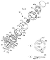
次に、図6〜図8を参照して、操作部81について詳細に説明する。図6は、操作部81の構成を説明するための図である。図7は、操作部81における各種検出器およびランプと操作部81の構造物との関係を説明するための図である。図6においては、(a)に操作部81の分解斜視図が示され、(b)に操作部81に含まれるカバープレート815の裏面図(ただし、裏面の突起部8150の構成を明確化するために固定部815aについては図示を省略している)が示され、(c)にカバープレート815の側面図(ただし、裏面の突起部8150の構成を明確化するために固定部815aについては図示を省略している)が示される。図7においては、(a)に各種検出器および各種ランプの配置状態を示す操作部81の平面図が示され、(b)に操作部81の側面図が示され、(c)に(a)のA−A断面図が示される。図8は、操作部81の各種状態を示すための縦断面図である。   Next, the operation unit 81 will be described in detail with reference to FIGS. FIG. 6 is a diagram for explaining the configuration of the operation unit 81. FIG. 7 is a diagram for explaining the relationship between various detectors and lamps in the operation unit 81 and the structure of the operation unit 81. 6A is an exploded perspective view of the operation unit 81, and FIG. 6B is a back view of the cover plate 815 included in the operation unit 81 (however, the configuration of the protrusion 8150 on the back surface is clarified). Therefore, the fixing portion 815a is not shown in the drawing, and (c) is a side view of the cover plate 815 (however, the fixing portion 815a is not shown in order to clarify the configuration of the protruding portion 8150 on the back surface). Is omitted). In FIG. 7, (a) shows a plan view of the operation unit 81 showing the arrangement of various detectors and various lamps, (b) shows a side view of the operation unit 81, and (c) shows (a A-A cross-sectional view of FIG. FIG. 8 is a longitudinal sectional view for illustrating various states of the operation unit 81.

図6を参照して、操作部81は、押圧操作部811、回転操作部812、ボタンハウジング813、ボタンバネ814、カバープレート815、ダイヤルベース816、ボタンベース817、および、操作部基板818を含む。   Referring to FIG. 6, the operation unit 81 includes a pressing operation unit 811, a rotation operation unit 812, a button housing 813, a button spring 814, a cover plate 815, a dial base 816, a button base 817, and an operation unit substrate 818.

押圧操作部811は、樹脂製で半透明の円形ボタン状の部材である。ボタンハウジング813は、上部に押圧操作部811が嵌込まれ、押圧操作部811の操作に応じて前後左右方向および上下方向に動作する部材であり、下部に、押圧操作部811が前後左右方向および下方向のうちのどの方向に操作されたかを検出するために必要となる4つの突起部813aが設けられている。また、ボタンハウジング813の外周部には、押圧操作部811において遊技者が操作すべき前後左右の4つの方向(前方向部、後方向部、右方向部、左方向部)を発光させるために操作部81において下方から上方へ光を導く4つの光導部813bが形成されている。ボタンハウジング813の下面側には、コイルバネよりなるボタンバネ814の一方端部が取付けられている。   The pressing operation unit 811 is a resin-made semitransparent circular button-shaped member. The button housing 813 is a member in which a pressing operation unit 811 is fitted in the upper part and operates in the front / rear and left / right directions and the upper / lower direction in accordance with the operation of the pressing operation unit 811. Four protrusions 813a necessary for detecting which one of the downward directions is operated are provided. In addition, in order to cause the outer periphery of the button housing 813 to emit light in four directions (front direction, rear direction, right direction, and left direction) that the player should operate in the pressing operation unit 811. In the operation portion 81, four light guide portions 813b that guide light from below to above are formed. One end of a button spring 814 made of a coil spring is attached to the lower surface side of the button housing 813.

ボタンベース817は、押圧操作部811、ボタンハウジング813、回転操作部812、ボタンバネ814、カバープレート815、および、ダイヤルベース816が上部に付けられ、操作部基板818が下部に取付けられる樹脂製の部材である。ボタンベース817においては、ボタンハウジング813を内部空間に受入れることが可能な形状の筒状壁部817aが上部に形成されている。そして、ボタンベース817においては、操作部81を打球供給皿3に設けられた取付部に取付けるための複数の爪部817bが形成されている。   The button base 817 has a pressing operation portion 811, a button housing 813, a rotation operation portion 812, a button spring 814, a cover plate 815, and a dial base 816 attached to the upper portion, and a resin member on which the operation portion substrate 818 is attached to the lower portion. It is. In the button base 817, a cylindrical wall portion 817a having a shape capable of receiving the button housing 813 in the internal space is formed in the upper portion. In the button base 817, a plurality of claw portions 817b for attaching the operation portion 81 to an attachment portion provided in the hit ball supply tray 3 are formed.

図6の(a)に示すように、カバープレート815は、環状に形成された金属製の部材であり、内周側にボタンハウジング813が挿通される。図6の(b)、(c)に示すように、カバープレート815の環状部の下面側には、クリック感(カチッ、カチッという音をさせて所定回転量ごとに回転動作が区切られていることを体感させる操作感覚)を生じさせるための複数(2つ)の突起8151が形成された突起部8150が設けられている。突起部8150は、板バネ状の部材の中間部においてその部材の一部を曲げ加工して突出させた突起8151を有し、板バネ状の部材の弾性力により突起8151の位置が揺動(この例では上下動)可能な形状で構成されている。また、図6の(a)に示すように、カバープレート815の四方には、カバープレート815をダイヤルベース816の上部に固定するための4つの固定部815aが設けられている。   As shown in FIG. 6A, the cover plate 815 is a metal member formed in an annular shape, and the button housing 813 is inserted through the inner periphery thereof. As shown in FIGS. 6B and 6C, on the lower surface side of the annular portion of the cover plate 815, a click feeling (clicking, clicking sound) is made to divide the rotation operation for each predetermined rotation amount. There is provided a protrusion 8150 in which a plurality of (two) protrusions 8151 for generating a sense of operation) are formed. The protruding portion 8150 has a protrusion 8151 that is formed by bending a part of the member at the intermediate portion of the leaf spring-like member, and the position of the protrusion 8151 is swung by the elastic force of the leaf spring-like member ( In this example, it has a shape that can be moved up and down). As shown in FIG. 6A, four fixing portions 815 a for fixing the cover plate 815 to the upper part of the dial base 816 are provided on the four sides of the cover plate 815.

ダイヤルベース816は、回転操作部812の操作に応じて回転する環状の樹脂製の部材であり、回転操作部812が嵌込まれる筒状壁部816cが上部に形成されている。ダイヤルベース816の内周側には、ボタンハウジング813が挿通される。また、ダイヤルベース816の外周には、前述のカバープレート815の突起8151との関係でクリック感を生じさせるための複数の凹凸部が連続的に形成されたクリック感部816bが周設されている。また、ダイヤルベース816の下面側には、回転操作部812の回転を検出するための回転検出用壁部816aが所定間隔で環状(同心円状)に配置された態様で設けられている。   The dial base 816 is an annular resin member that rotates in accordance with the operation of the rotation operation unit 812, and has a cylindrical wall portion 816c into which the rotation operation unit 812 is fitted. A button housing 813 is inserted through the inner peripheral side of the dial base 816. Further, on the outer periphery of the dial base 816, there is provided a click feeling portion 816b in which a plurality of concave and convex portions for continuously generating a click feeling in relation to the protrusion 8151 of the cover plate 815 are continuously formed. . Further, on the lower surface side of the dial base 816, a rotation detection wall portion 816a for detecting the rotation of the rotation operation portion 812 is provided in a form of being arranged in an annular shape (concentric circle shape) at a predetermined interval.

このようなダイヤルベース816は、ボタンベース817の筒状壁部817aの外周面に摺接し、その外周面に沿って回転可能となるように、ボタンベース817の筒状壁部817aを内部に挿通する態様でボタンベース817に嵌め入れられる。そして、カバープレート815は、ダイヤルベース816の筒状壁部816cを上側から押さえた状態で、固定部815aをボタンベース817に設けられた固定部817c(図7(b)参照)に固定する態様でボタンベース817に取付けられる。このような状態では、ダイヤルベース816の筒状壁部816cの一部が、カバープレート815の内周側から上方へ突出する。その突出した筒状壁部816cに回転操作部812が取付けられることにより、回転操作部812の回転動作にダイヤルベース816が連動する。カバープレート815下面側の突起部8150の突起8151は、突起部8150の弾性力により、ダイヤルベース816に連続的に形成された凹凸部へ向けて付勢される。このような場合において、ダイヤルベース816に連続的に形成された凹凸部にカバープレート815下面側の突起部8150の突起8151が出入りすることにより、回転操作部812をたとえば15度のような所定角度(所定回転量)ずつ回転操作するごとにクリック感を生じさせることができる。   Such a dial base 816 is slidably contacted with the outer peripheral surface of the cylindrical wall portion 817a of the button base 817, and is inserted through the cylindrical wall portion 817a of the button base 817 so as to be rotatable along the outer peripheral surface. In this manner, the button base 817 is fitted. The cover plate 815 fixes the fixing portion 815a to the fixing portion 817c (see FIG. 7B) provided on the button base 817 in a state where the cylindrical wall portion 816c of the dial base 816 is pressed from above. Is attached to the button base 817. In such a state, a part of the cylindrical wall portion 816 c of the dial base 816 protrudes upward from the inner peripheral side of the cover plate 815. By attaching the rotation operation portion 812 to the protruding cylindrical wall portion 816c, the dial base 816 is interlocked with the rotation operation of the rotation operation portion 812. The protrusion 8151 of the protrusion 8150 on the lower surface side of the cover plate 815 is urged toward the uneven part continuously formed on the dial base 816 by the elastic force of the protrusion 8150. In such a case, the protrusion 8151 of the protrusion 8150 on the lower surface side of the cover plate 815 enters and exits the uneven part continuously formed on the dial base 816, so that the rotation operation part 812 is moved at a predetermined angle such as 15 degrees. A click feeling can be generated each time the (predetermined amount of rotation) is rotated.

たとえば、ダイヤルベース816に連続的に形成された凹凸部の凹部は、カバープレート815の下面側の突起が当接したときに、その突起を下方へ滑らせて凸部における底部に入るように誘導することが可能な斜面を形成する形状で構成されている。したがって、回転操作部812が回転操作されることに応じて、ある凹部から次の凸部の頂点へ突起8151が移動し、その突起8151が凸部の頂点を超えて次の凹部に入ると、その後特に操作力を加えなくても、その突起8151は突起部8150の部材の弾性力により付勢されて、斜面を下方へ滑べって次の凸部における底部に入る。したがって、回転操作部812の回転操作時には、ある凹部から次の凹部へ1クリック分操作するときにおいて、それら凹部間の凸部の頂点を突起8151が通過すると、逆方向へ回転操作しない限りその突起8151が次の凹部の底部へ誘導されるので、そのような凸部の頂点を突起8151が通過したタイミングで、1クリック分の操作が行なわれたと判別することが可能である。回転操作部812の回転操作に応じてこのような動作が行なわれることにより、所定の回転量ごとにクリック感が生じることとなる。   For example, the concave portion of the concavo-convex portion formed continuously on the dial base 816 is guided so that when the projection on the lower surface side of the cover plate 815 comes into contact, the projection slides downward to enter the bottom portion of the convex portion. It is comprised in the shape which forms the slope which can do. Therefore, in response to the rotation operation of the rotation operation unit 812, the projection 8151 moves from a certain concave portion to the vertex of the next convex portion, and when the projection 8151 enters the next concave portion beyond the vertex of the convex portion, Thereafter, even if no operating force is applied, the protrusion 8151 is urged by the elastic force of the member of the protrusion 8150, and slides down the slope to enter the bottom of the next protrusion. Therefore, when the rotation operation portion 812 is rotated, when the projection 8151 passes through the apex of the convex portion between the concave portions when the operation is performed for one click from one concave portion to the next concave portion, the protrusion is required unless it is rotated in the opposite direction. Since 8151 is guided to the bottom of the next concave portion, it is possible to determine that an operation for one click has been performed at the timing when the projection 8151 passes through the apex of the convex portion. By performing such an operation according to the rotation operation of the rotation operation unit 812, a click feeling is generated for each predetermined rotation amount.

また、押圧操作部811およびボタンバネ814が取付けられたボタンハウジング813については、ボタンバネ814の他端部がボタンベース817における筒状壁部817a内部の底面に設けられたボタンバネ取付部817c(図7(b)参照)に取付けられる。図8(a)または図8(c)に示すように、押圧操作部811が押圧操作された後、ボタンバネ814の伸縮力に基づいて、図8(b)に示すように、押圧操作された後の押圧操作部811が元の位置まで戻される。   Further, for the button housing 813 to which the pressing operation portion 811 and the button spring 814 are attached, the other end portion of the button spring 814 is a button spring attaching portion 817c provided on the bottom surface inside the cylindrical wall portion 817a of the button base 817 (FIG. 7 ( b)). As shown in FIG. 8A or 8C, after the pressing operation portion 811 is pressed, the pressing operation is performed as shown in FIG. 8B based on the expansion / contraction force of the button spring 814. The subsequent pressing operation unit 811 is returned to the original position.

ボタンベース817の下面部には、操作部基板818がビス止めにより取付けられる。図7(a)のように、操作部基板818は、円板型に形成され、各種の電気部品が搭載される基板である。操作部基板818の上面側には、第1押圧検出器81a、第2押圧検出器81b、第3押圧検出器81c、第4押圧検出器81d、第1回転検出器81e、第2回転検出器81f、第1操作部ランプ82a、第2操作部ランプ82b、第3操作部ランプ82c、第4操作部ランプ82d、第5操作部ランプ82e、第6操作部ランプ82f、第7操作部ランプ82g、第8操作部ランプ82h、および、第9操作部ランプ82iが設けられている。   An operation unit substrate 818 is attached to the lower surface of the button base 817 with screws. As shown in FIG. 7A, the operation unit substrate 818 is a substrate that is formed in a disc shape and on which various electrical components are mounted. On the upper surface side of the operation unit substrate 818, a first press detector 81a, a second press detector 81b, a third press detector 81c, a fourth press detector 81d, a first rotation detector 81e, and a second rotation detector 81f, 1st operation part lamp 82a, 2nd operation part lamp 82b, 3rd operation part lamp 82c, 4th operation part lamp 82d, 5th operation part lamp 82e, 6th operation part lamp 82f, 7th operation part lamp 82g , An eighth operation unit lamp 82h and a ninth operation unit lamp 82i are provided.

第1押圧検出器81a、第2押圧検出器81b、第3押圧検出器81c、および、第4押圧検出器81dは、前述したような押圧操作部811による4方向の方向選択操作と決定操作とを検出するために設けられた検出器であり、操作部基板818の中心部を中心とした同心円上に所定間隔で配置されている。各押圧操作器は、発光部と受光部とを備えたフォトセンサよりなり、図8(a)または図8(c)に示すように、前述のボタンハウジング813の突起部813aが内部空間に入ったときに光が遮断されることに基づいて、押圧操作部811が操作されたことを検出する。より具体的に、ボタンハウジング813の4つの突起部813aと、第1押圧検出器81a、第2押圧検出器81b、第3押圧検出器81c、および、第4押圧検出器81dのそれぞれとの関係は次の通りである。   The first press detector 81a, the second press detector 81b, the third press detector 81c, and the fourth press detector 81d are four-direction direction selection operation and determination operation by the press operation unit 811 as described above. , And is arranged at a predetermined interval on a concentric circle with the central portion of the operation unit substrate 818 as the center. Each pressing operation device is composed of a photosensor having a light emitting portion and a light receiving portion. As shown in FIG. 8A or 8C, the protrusion 813a of the button housing 813 described above enters the internal space. It is detected that the pressing operation unit 811 has been operated based on the fact that the light is interrupted. More specifically, the relationship between the four protrusions 813a of the button housing 813 and each of the first press detector 81a, the second press detector 81b, the third press detector 81c, and the fourth press detector 81d. Is as follows.

図8(a)に示すように、押圧操作部811の左方向部が押圧操作されたときには、突起部813aのうち、押圧操作部811の左方向部の直下に存在する突起部が第2押圧検出器81bの内部に入ることに基づいて、左方向部が押圧操作されたことが検出される。また、押圧操作部811の右方向部が押圧操作されたときには、突起部813aのうち、押圧操作部811の右方向部の直下に存在する突起部が第4押圧検出器81dの内部に入ることに基づいて、右方向部が押圧操作されたことが検出される。また、押圧操作部811の前方向部が押圧操作されたときには、突起部813aのうち、押圧操作部811の前方向部の直下に存在する突起部が第1押圧検出器81aの内部に入ることに基づいて、前方向部が押圧操作されたことが検出される。また、押圧操作部811の後方向の部分が押圧操作されたときには、突起部813aのうち、押圧操作部811の後方向部の直下に存在する突起部が第3押圧検出器81cの内部に入ることに基づいて、後方向の部分が押圧操作されたことが検出される。   As shown in FIG. 8A, when the left direction portion of the pressing operation portion 811 is pressed, the protrusion portion that exists immediately below the left direction portion of the pressing operation portion 811 among the protrusion portions 813 a is the second pressing portion. Based on entering the inside of the detector 81b, it is detected that the left direction portion has been pressed. In addition, when the right direction portion of the pressing operation portion 811 is pressed, the protruding portion that exists immediately below the right direction portion of the pressing operation portion 811 among the protruding portions 813a enters the inside of the fourth press detector 81d. Based on this, it is detected that the right direction portion has been pressed. Further, when the forward direction portion of the pressing operation portion 811 is pressed, the protruding portion existing immediately below the forward direction portion of the pressing operation portion 811 among the protruding portions 813a enters the inside of the first press detector 81a. Based on the above, it is detected that the front portion has been pressed. Further, when the rear portion of the pressing operation portion 811 is pressed, the protruding portion that exists immediately below the rear portion of the pressing operation portion 811 among the protruding portions 813a enters the inside of the third press detector 81c. Based on this, it is detected that the backward portion has been pressed.

また、図8(c)に示すように、押圧操作部811の中央部が正常に押圧操作されたときには、通常的に、第1押圧検出器81a、第2押圧検出器81b、第3押圧検出器81c、および、第4押圧検出器81dのうちの少なくとも2つの内部に突起部813aが入る。これにより、第1押圧検出器81a、第2押圧検出器81b、第3押圧検出器81c、および、第4押圧検出器81dのうちの少なくとも2つに突起部813aが入ることに基づいて、押圧操作部811の中央部が押圧操作されたことが検出される。   Further, as shown in FIG. 8C, when the central portion of the pressing operation unit 811 is normally pressed, the first pressing detector 81a, the second pressing detector 81b, and the third pressing detection are usually performed. A protrusion 813a is inserted into at least two of the device 81c and the fourth press detector 81d. Accordingly, the pressing portion 813a is inserted into at least two of the first press detector 81a, the second press detector 81b, the third press detector 81c, and the fourth press detector 81d. It is detected that the central portion of the operation unit 811 has been pressed.

また、第1回転検出器81eおよび第2回転検出器81fは、回転操作部812による左回転操作と右回転操作とを検出するために設けられた検出器である。図7(a)に示すように、各回転検出器は、発光部と受光部とを備えたフォトセンサよりなり、前述のダイヤルベース816が回転したときに回転検出用壁部816aが発光部と受光部の間を通過できるような位置に設けられる。第1回転検出器81eと、第2回転検出器81fとの位置関係は、たとえば第1回転検出器81eがある回転検出用壁部816aを検出しているときに第2回転検出器81fが他の回転検出用壁部816aを検出していない状態となるように、所定距離だけ離隔して配置されている。   The first rotation detector 81e and the second rotation detector 81f are detectors provided for detecting a left rotation operation and a right rotation operation by the rotation operation unit 812. As shown in FIG. 7A, each rotation detector includes a photosensor having a light emitting portion and a light receiving portion, and when the dial base 816 is rotated, the rotation detection wall portion 816a is a light emitting portion. It is provided at a position where it can pass between the light receiving parts. The positional relationship between the first rotation detector 81e and the second rotation detector 81f is such that, for example, when the first rotation detector 81e detects a certain rotation detection wall 816a, the second rotation detector 81f The rotation detection wall portion 816a is not separated from the rotation detection wall portion 816a and is spaced apart by a predetermined distance.

各回転検出器は、ダイヤルベース816の回転検出用壁部816aが発光部と受光部との間に入ったときに発光部から受光部への光が遮断される。回転検出用壁部816aは、前述のように所定間隔で配置されているので、各回転検出器から出力される検出信号は、ダイヤルベース816が回転しているときに、回転検出用壁部816aを検出していない状態であるオン状態と、回転検出用壁部816aを検出している状態となるオフ状態とを繰返すパルス信号となる。演出制御用マイクロコンピュータ100では、後述するように、第1回転検出器81eの検出信号の状態と第2回転検出器81fの検出信号の状態との関係に基づいて、回転操作部812による回転操作が検出される。   In each rotation detector, when the rotation detection wall portion 816a of the dial base 816 enters between the light emitting portion and the light receiving portion, light from the light emitting portion to the light receiving portion is blocked. Since the rotation detection wall portions 816a are arranged at a predetermined interval as described above, the detection signals output from the respective rotation detectors are detected when the dial base 816 is rotating. Is a pulse signal that repeats an on state in which no rotation is detected and an off state in which the rotation detection wall portion 816a is detected. In the effect control microcomputer 100, as will be described later, based on the relationship between the state of the detection signal of the first rotation detector 81e and the state of the detection signal of the second rotation detector 81f, the rotation operation by the rotation operation unit 812 is performed. Is detected.

操作部基板818の中央部には、第5操作部ランプ82eが設けられている。第5操作部ランプ82eは、押圧操作部811のうち、前述の決定操作を行なうときに操作すべき位置である押圧操作部811の中央部を発光させるためのLEDよりなる。第5操作部ランプ82eからの光が、ボタンベース817の内部空間およびボタンハウジング813の内部空間を通り、操作部基板818の中央部に達することにより(図7(c)参照)、押圧操作部811の中央部(以下、決定操作部と呼ぶ場合もある)が発光することとなる。   A fifth operation unit lamp 82e is provided at the center of the operation unit substrate 818. The fifth operation portion lamp 82e is an LED for causing the central portion of the pressing operation portion 811, which is a position to be operated when performing the above-described determination operation, of the pressing operation portion 811 to emit light. When the light from the fifth operation portion lamp 82e passes through the internal space of the button base 817 and the internal space of the button housing 813 and reaches the central portion of the operation portion substrate 818 (see FIG. 7C), the pressing operation portion. The central portion of 811 (hereinafter sometimes referred to as a determination operation portion) emits light.

第1操作部ランプ82a〜第4操作部ランプ82dおよび第6操作部ランプ82f〜第4操作部ランプ82iは、操作部基板818において、操作部基板818の中央部から、第1押圧検出器81a〜第4押圧検出器81dが配置された位置よりも外側の位置に、操作部基板818の中心部を中心とした同心円上に所定間隔で配置されている。第1操作部ランプ82aは、第1押圧検出器81aの近傍に設けられている。第2操作部ランプ82bは、第2押圧検出器81bの近傍に設けられている。第3操作部ランプ82cは、第3押圧検出器81cの近傍に設けられている。第4操作部ランプ82dは、第4押圧検出器81dの近傍に設けられている。第6操作部ランプ82fは、第1操作部ランプ82aと、第2操作部ランプ82bとの間に設けられている。第7操作部ランプ82gは、第2操作部ランプ82bと、第3操作部ランプ82cとの間に設けられている。第8操作部ランプ82hは、第3操作部ランプ82cと、第4操作部ランプ82dとの間に設けられている。第9操作部ランプ82iは、第4操作部ランプ82dと、第1操作部ランプ82aとの間に設けられている。   The first operation unit lamp 82a to the fourth operation unit lamp 82d and the sixth operation unit lamp 82f to the fourth operation unit lamp 82i are arranged on the operation unit substrate 818 from the central portion of the operation unit substrate 818. ˜ are arranged at predetermined intervals on concentric circles centering on the central portion of the operation unit substrate 818 at positions outside the position where the fourth press detector 81d is arranged. The first operation portion lamp 82a is provided in the vicinity of the first press detector 81a. The second operation portion lamp 82b is provided in the vicinity of the second press detector 81b. The third operation unit lamp 82c is provided in the vicinity of the third press detector 81c. The fourth operation portion lamp 82d is provided in the vicinity of the fourth press detector 81d. The sixth operation unit lamp 82f is provided between the first operation unit lamp 82a and the second operation unit lamp 82b. The seventh operation unit lamp 82g is provided between the second operation unit lamp 82b and the third operation unit lamp 82c. The eighth operation unit lamp 82h is provided between the third operation unit lamp 82c and the fourth operation unit lamp 82d. The ninth operation unit lamp 82i is provided between the fourth operation unit lamp 82d and the first operation unit lamp 82a.

第1操作部ランプ82aは、押圧操作部811のうち、前方向の方向選択操作を行なうときに操作すべき位置である押圧操作部811の前方向部を発光させるためのLEDよりなる。第1操作部ランプ82aからの光が、ボタンベース817の内部空間およびボタンハウジング813における前方向部発光のための光を導く光導部813bを通り、操作部基板818の前方向部に達することにより、押圧操作部811の前方向部が発光することとなる。   The first operation portion lamp 82a is composed of an LED for causing the front direction portion of the pressing operation portion 811 that is a position to be operated when performing the forward direction selection operation of the pressing operation portion 811 to emit light. The light from the first operation portion lamp 82a passes through the inner space of the button base 817 and the light guide portion 813b that guides the light for light emission in the front direction in the button housing 813, and reaches the front direction portion of the operation portion substrate 818. The forward direction portion of the pressing operation portion 811 emits light.

第2操作部ランプ82bは、押圧操作部811のうち、左方向の方向選択操作を行なうときに操作すべき位置である押圧操作部811の左方向部を発光させるためのLEDよりなる。第2操作部ランプ82bからの発光が、ボタンベース817の内部空間およびボタンハウジング813における左方向部発光のための光を導く光導部813bを通り、操作部基板818の左方向部に達することにより、押圧操作部811の左方向部が発光することとなる。   The second operation portion lamp 82b is composed of an LED for causing the left direction portion of the pressing operation portion 811, which is a position to be operated when performing the left direction selection operation, of the pressing operation portion 811 to emit light. Light emitted from the second operation portion lamp 82b passes through the inner space of the button base 817 and the light guide portion 813b that guides light for light emission in the left direction portion in the button housing 813, and reaches the left direction portion of the operation portion substrate 818. The left direction part of the pressing operation part 811 emits light.

第3操作部ランプ82cは、押圧操作部811のうち、後方向の方向選択操作を行なうときに操作すべき位置である押圧操作部811の後方向部を発光させるためのLEDよりなる。第3操作部ランプ82cからの光が、ボタンベース817の内部空間およびボタンハウジング813における後方向部発光のための光を導く光導部813bを通り、操作部基板818の後方向部に達することにより、押圧操作部811の後方向部が発光することとなる。   The third operation portion lamp 82c is an LED for causing the rear portion of the pressing operation portion 811 that is a position to be operated when performing the backward direction selection operation of the pressing operation portion 811 to emit light. The light from the third operation portion lamp 82c passes through the inner space of the button base 817 and the light guide portion 813b for guiding the light for the rear direction light emission in the button housing 813, and reaches the rear direction portion of the operation portion substrate 818. Then, the rear portion of the pressing operation portion 811 emits light.

第4操作部ランプ82dは、押圧操作部811のうち、右方向の方向選択操作を行なうときに操作すべき位置である押圧操作部811の右方向部を発光させるためのLEDよりなる。第4操作部ランプ82dからの光が、ボタンベース817の内部空間およびボタンハウジング813における右方向部発光のための光を導く光導部813bを通り、操作部基板818の右方向部に達することにより、押圧操作部811の右方向部が発光することとなる。   The fourth operation portion lamp 82d is an LED for causing the right direction portion of the pressing operation portion 811 that is a position to be operated when performing the right direction selection operation of the pressing operation portion 811 to emit light. The light from the fourth operation portion lamp 82d passes through the inner space of the button base 817 and the light guide portion 813b that guides the light for light emission in the right direction portion in the button housing 813, and reaches the right direction portion of the operation portion substrate 818. The right direction part of the pressing operation part 811 emits light.

また、第6操作部ランプ82f〜第9操作部ランプ82iは、第1操作部ランプ82a〜第4操作部ランプ82dと合せて、回転操作部812の回転操作を行なうときに押圧操作部811の全周を発光させることより、回転操作を案内するためのLEDよりなる。第6操作部ランプ82f〜第9操作部ランプ82iは、
ボタンベース817の内部空間およびボタンハウジング813を通り、操作部基板818に達する。回転操作部812の回転操作を案内するときには、第1操作部ランプ82a〜第4操作部ランプ82dおよび第6操作部ランプ82f〜第9操作部ランプ82iの合計8つのランプが発光することにより、押圧操作部811の全周が発光し、押圧操作部811の外周に設けられた回転操作部812の回転操作を案内することとなる。
In addition, the sixth operation unit lamp 82f to the ninth operation unit lamp 82i, together with the first operation unit lamp 82a to the fourth operation unit lamp 82d, are used when the rotation operation unit 812 is rotated. It comprises LEDs for guiding the rotation operation by causing the entire circumference to emit light. The sixth operation unit lamp 82f to the ninth operation unit lamp 82i are:
It passes through the internal space of the button base 817 and the button housing 813 and reaches the operation unit substrate 818. When guiding the rotation operation of the rotation operation unit 812, a total of eight lamps of the first operation unit lamp 82a to the fourth operation unit lamp 82d and the sixth operation unit lamp 82f to the ninth operation unit lamp 82i emit light. The entire circumference of the pressing operation unit 811 emits light and guides the rotation operation of the rotating operation unit 812 provided on the outer periphery of the pressing operation unit 811.

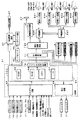
図9は、主基板(遊技制御基板)31における回路構成の一例を示すブロック図である。なお、図9には、払出制御基板37および演出制御基板80等も示されている。主基板31には、プログラムに従ってパチンコ遊技機1を制御する遊技制御用マイクロコンピュータ(遊技制御手段に相当)560が搭載されている。遊技制御用マイクロコンピュータ560は、ゲーム制御(遊技進行制御)用のプログラム等を記憶するROM54、ワークメモリとして使用される記憶手段としてのRAM55、プログラムに従って制御動作を行なうCPU56、I/Oポート部57、およびパラレルデータをシリアルデータに変換して出力するシリアル出力回路を含む。この実施の形態では、ROM54およびRAM55は遊技制御用マイクロコンピュータ560に内蔵されている。すなわち、遊技制御用マイクロコンピュータ560は、1チップマイクロコンピュータである。1チップマイクロコンピュータには、少なくともCPU56のほかRAM55が内蔵されていればよく、ROM54は外付けであっても内蔵されていてもよい。また、I/Oポート部57は、外付けであってもよい。   FIG. 9 is a block diagram illustrating an example of a circuit configuration in the main board (game control board) 31. FIG. 9 also shows the payout control board 37, the effect control board 80, and the like. A game control microcomputer (corresponding to a game control means) 560 for controlling the pachinko gaming machine 1 according to a program is mounted on the main board 31. The game control microcomputer 560 includes a ROM 54 for storing a game control (game progress control) program and the like, a RAM 55 as storage means used as a work memory, a CPU 56 for performing control operations in accordance with the program, and an I / O port unit 57. And a serial output circuit for converting parallel data into serial data and outputting the serial data. In this embodiment, the ROM 54 and the RAM 55 are built in the game control microcomputer 560. That is, the game control microcomputer 560 is a one-chip microcomputer. The one-chip microcomputer only needs to incorporate at least the CPU 56 and the RAM 55, and the ROM 54 may be external or built-in. The I / O port unit 57 may be externally attached.

遊技制御用マイクロコンピュータ560には、さらに、ハードウェア乱数を発生する乱数回路が内蔵されている。   The game control microcomputer 560 further includes a random number circuit for generating hardware random numbers.

なお、遊技制御用マイクロコンピュータ560においてCPU56がROM54に格納されているプログラムに従って制御を実行するので、以下、遊技制御用マイクロコンピュータ560(またはCPU56)が実行する(または、処理を行なう)ということは、具体的には、CPU56がプログラムに従って制御を実行することである。このことは、主基板31以外の他の基板に搭載されているマイクロコンピュータについても同様である。   In the game control microcomputer 560, the CPU 56 executes control in accordance with the program stored in the ROM 54. Therefore, the game control microcomputer 560 (or the CPU 56) executes (or performs processing) hereinafter. Specifically, the CPU 56 executes control according to a program. The same applies to microcomputers mounted on substrates other than the main substrate 31.

また、ゲートスイッチ32a、第1始動口スイッチ13a、第2始動口スイッチ14a、カウントスイッチ23、入賞口スイッチ29a,30a,33a,39aからの検出信号を遊技制御用マイクロコンピュータ560に与える入力ドライバ回路58も主基板31に搭載されている。また、可変入賞球装置15を開閉するソレノイド16、および大入賞口を形成する特別可変入賞球装置20を開閉するソレノイド21を遊技制御用マイクロコンピュータ560からの指令に従って駆動する出力回路59も主基板31に搭載されている。   Also, an input driver circuit for supplying detection signals from the gate switch 32a, the first start port switch 13a, the second start port switch 14a, the count switch 23, and the winning port switches 29a, 30a, 33a and 39a to the game control microcomputer 560. 58 is also mounted on the main board 31. The main board also includes an output circuit 59 for driving the solenoid 16 for opening and closing the variable winning ball device 15 and the solenoid 21 for opening and closing the special variable winning ball device 20 that forms a big winning opening in accordance with a command from the game control microcomputer 560. 31.

また、遊技制御用マイクロコンピュータ560は、特別図柄を変動表示する特別図柄表示器8、普通図柄を変動表示する普通図柄表示器10、特別図柄保留記憶表示器18および普通図柄保留記憶表示器41の表示制御を行なう。   In addition, the game control microcomputer 560 includes a special symbol display 8 for variably displaying special symbols, a normal symbol display 10 for variably displaying normal symbols, a special symbol hold memory indicator 18 and a normal symbol hold memory indicator 41. Perform display control.

また、遊技制御用マイクロコンピュータ560が搭載するシリアル出力回路78は、シフトレジスタ等によって構成され、CPU56が出力する演出制御コマンドをシリアルデータに変換して、中継基板77を介して演出制御基板80に送信する。また、シリアル出力回路78は、CPU56が出力する制御信号をシリアルデータに変換して、中継基板77を介して特別図柄表示器8や特別図柄保留記憶表示器18、普通図柄表示器10、普通図柄保留記憶表示器41に出力する。なお、特別図柄表示器8、特別図柄保留記憶表示器18、普通図柄表示器10および普通図柄保留記憶表示器41には、シリアルデータをパラレルデータに変換するシリアル−パラレル変換ICがそれぞれ設けられ、中継基板77からの制御信号をパラレルデータに変換して、特別図柄表示器8や特別図柄保留記憶表示器18、普通図柄表示器10、普通図柄保留記憶表示器41に供給される。   Further, the serial output circuit 78 mounted on the game control microcomputer 560 is constituted by a shift register or the like, converts the effect control command output from the CPU 56 into serial data, and sends it to the effect control board 80 via the relay board 77. Send. The serial output circuit 78 converts the control signal output from the CPU 56 into serial data, and via the relay board 77, the special symbol display 8, the special symbol hold storage display 18, the normal symbol display 10, and the normal symbol. Output to the on-hold storage display 41. The special symbol display 8, the special symbol hold storage display 18, the normal symbol display 10 and the normal symbol hold storage display 41 are provided with serial-parallel conversion ICs for converting serial data into parallel data, respectively. The control signal from the relay board 77 is converted into parallel data and supplied to the special symbol display 8, the special symbol hold storage display 18, the normal symbol display 10, and the normal symbol hold storage display 41.

なお、大当り遊技状態の発生を示す大当り情報等の情報出力信号をホールコンピュータ等の外部装置に対して出力する情報出力回路(図示せず)も主基板31に搭載されている。   An information output circuit (not shown) that outputs an information output signal such as jackpot information indicating the occurrence of a jackpot gaming state to an external device such as a hall computer is also mounted on the main board 31.

この実施の形態では、演出制御基板80に搭載されている演出制御手段(演出制御用マイクロコンピュータで構成される。)が、中継基板77を介して遊技制御用マイクロコンピュータ560からの演出制御コマンドをシリアルデータ方式として受信し、飾り図柄を変動表示する変動表示装置9の表示制御を行なう。   In this embodiment, the effect control means (configured by the effect control microcomputer) mounted on the effect control board 80 receives the effect control command from the game control microcomputer 560 via the relay board 77. It receives as a serial data system and performs display control of the variable display device 9 which displays the decorative pattern in a variable manner.

また、演出制御基板80に搭載されている演出制御用マイクロコンピュータ100が、遊技盤6に設けられているセンター飾り用ランプ125a〜125fおよびステージランプ126a〜126fの表示制御を行なうとともに、枠側に設けられている天枠ランプ281a〜281l、左枠ランプ282a〜282f、右枠ランプ283a〜283fおよび第1操作部ランプ82a〜第9操作部ランプ82iの表示制御を行ない、スピーカ27からの音出力の制御を行なう。   In addition, the production control microcomputer 100 mounted on the production control board 80 performs display control of the center decoration lamps 125a to 125f and the stage lamps 126a to 126f provided on the game board 6, and on the frame side. Display control of the provided top frame lamps 281a to 281l, left frame lamps 282a to 282f, right frame lamps 283a to 283f, and first operation unit lamps 82a to ninth operation unit lamps 82i, and sound output from the speaker 27 Control.

また、演出制御基板80の演出制御用マイクロコンピュータ100には、演出制御手段が出力する各ランプ125a〜125f,126a〜126f,281a〜281l,282a〜282f,283a〜283f,82a〜82iを表示制御するための制御信号をパラレルデータからシリアルデータに変換するシリアル出力回路353が搭載されている。また、演出制御基板80の演出制御用マイクロコンピュータ100には、入力したシリアルデータをパラレルデータに変換して演出制御手段に出力するシリアル入力回路354が搭載されている。したがって、演出制御手段は、シリアル出力回路353を介して制御信号をシリアルデータ方式として出力することによって、各ランプ125a〜125f,126a〜126f,281a〜281l,282a〜282f,283a〜283f,82a〜82iの表示制御を行なう。   In addition, the effect control microcomputer 100 of the effect control board 80 controls display of the lamps 125a to 125f, 126a to 126f, 281a to 281l, 282a to 282f, 283a to 283f, and 82a to 82i output from the effect control means. A serial output circuit 353 for converting a control signal for performing the conversion from parallel data to serial data is mounted. In addition, the effect control microcomputer 100 of the effect control board 80 is equipped with a serial input circuit 354 that converts the input serial data into parallel data and outputs the parallel data to the effect control means. Therefore, the effect control means outputs the control signal as a serial data system via the serial output circuit 353, whereby the lamps 125a to 125f, 126a to 126f, 281a to 281l, 282a to 282f, 283a to 283f, 82a to 82a. 82i display control is performed.

また、遊技盤側には、シリアルデータをパラレルデータに変換するためのシリアル−パラレル変換ICが搭載された盤側IC基板601が設けられている。盤側IC基板601は、中継基板606を介して演出制御基板80と接続される。また、遊技枠11側には、シリアルデータをパラレルデータに変換するためのシリアル−パラレル変換ICが搭載された各枠側IC基板602,603,604,605が設けられている。各枠側IC基板602,603,604,605は、中継基板606,607を介して演出制御基板80と接続される。   On the game board side, a board-side IC board 601 on which a serial-parallel conversion IC for converting serial data into parallel data is mounted. The board side IC substrate 601 is connected to the effect control substrate 80 via the relay substrate 606. On the game frame 11 side, frame-side IC substrates 602, 603, 604, and 605 on which serial-parallel conversion ICs for converting serial data into parallel data are provided. Each frame side IC substrate 602, 603, 604, 605 is connected to the effect control substrate 80 via the relay substrate 606, 607.

なお、図9に示すように、演出制御基板80、中継基板606および中継基板607は、バス型に1系統の配線ルートで接続される。   As shown in FIG. 9, the effect control board 80, the relay board 606, and the relay board 607 are connected to each other by a single wiring route in a bus shape.

図10は、中継基板77および演出制御基板80の回路構成例を示すブロック図である。なお、図10に示す例では、演出制御に関して演出制御基板80のみを設ける場合を示すが、ランプドライバ基板および音声出力基板を設けてもよい。この場合、ランプドライバ基板および音声出力基板には、マイクロコンピュータは搭載されていないが、マイクロコンピュータを搭載してもよい。   FIG. 10 is a block diagram illustrating a circuit configuration example of the relay board 77 and the effect control board 80. In addition, although the example shown in FIG. 10 shows the case where only the effect control board 80 is provided regarding the effect control, a lamp driver board and an audio output board may be provided. In this case, the lamp driver board and the sound output board are not equipped with a microcomputer, but may be equipped with a microcomputer.

演出制御基板80は、演出制御用CPU101、RAM(図示せず)、シリアル出力回路353、シリアル入力回路354、クロック信号出力部356および入力取込信号出力部357を含む演出制御用マイクロコンピュータ100を搭載している。なお、RAMは外付けであってもよい。演出制御基板80において、演出制御用CPU101は、内蔵または外付けのROM(図示せず)に格納されたプログラムに従って動作し、シリアル入力回路102および入力ポート103を介して演出制御コマンドを受信する。この場合、シリアル入力回路102は、シリアルデータ方式として受信した演出制御コマンドをパラレルデータに変換し出力する。また、演出制御用CPU101は、演出制御コマンドに基づいて、VDP(ビデオディスプレイプロセッサ)109に変動表示装置9の表示制御を行なわせる。   The effect control board 80 includes an effect control microcomputer 100 including an effect control CPU 101, a RAM (not shown), a serial output circuit 353, a serial input circuit 354, a clock signal output unit 356 and an input capture signal output unit 357. It is installed. The RAM may be externally attached. In the effect control board 80, the effect control CPU 101 operates in accordance with a program stored in a built-in or external ROM (not shown), and receives an effect control command via the serial input circuit 102 and the input port 103. In this case, the serial input circuit 102 converts the effect control command received as the serial data method into parallel data and outputs the parallel data. Further, the effect control CPU 101 causes the VDP (video display processor) 109 to perform display control of the variable display device 9 based on the effect control command.

この実施の形態では、演出制御用マイクロコンピュータ100と共動して変動表示装置9の表示制御を行なうVDP109が演出制御基板80に搭載されている。VDP109は、演出制御用マイクロコンピュータ100とは独立したアドレス空間を有し、そこにVRAMをマッピングする。VRAMは、画像データを展開するためのバッファメモリである。そして、VDP109は、VRAM内の画像データをフレームメモリを介して変動表示装置9に出力する。   In this embodiment, a VDP 109 that performs display control of the variable display device 9 in cooperation with the effect control microcomputer 100 is mounted on the effect control board 80. The VDP 109 has an address space independent of the production control microcomputer 100, and maps a VRAM therein. VRAM is a buffer memory for developing image data. The VDP 109 then outputs the image data in the VRAM to the variable display device 9 via the frame memory.

演出制御用CPU101は、受信した演出制御コマンドに従ってCGROM(図示せず)から必要なデータを読出すための指令をVDP109に出力する。CGROMは、変動表示装置9に表示されるキャラクタ画像データや動画像データ、具体的には、人物、文字、図形や記号等(飾り図柄を含む)、および背景画像のデータを予め格納しておくためのROMである。VDP109は、演出制御用CPU101の指令に応じて、CGROMから画像データを読出す。そして、VDP109は、読出した画像データに基づいて表示制御を実行する。   The effect control CPU 101 outputs to the VDP 109 a command for reading necessary data from a CGROM (not shown) in accordance with the received effect control command. The CGROM stores in advance character image data and moving image data displayed on the variable display device 9, specifically, a person, characters, figures, symbols, etc. (including decorative designs), and background image data. ROM. The VDP 109 reads the image data from the CGROM in response to a command from the effect control CPU 101. The VDP 109 executes display control based on the read image data.

中継基板77には、主基板31から入力された信号を演出制御基板80に向かう方向にしか通過させない(演出制御基板80から中継基板77への方向には信号を通過させない)信号方向規制手段としての単方向性回路74が搭載されている。単方向性回路として、たとえばダイオードやトランジスタが使用される。図10には、ダイオードが例示されている。   As a signal direction regulating means, the signal inputted from the main board 31 is allowed to pass through the relay board 77 only in the direction toward the effect control board 80 (the signal is not passed in the direction from the effect control board 80 to the relay board 77). The unidirectional circuit 74 is mounted. For example, a diode or a transistor is used as the unidirectional circuit. FIG. 10 illustrates a diode.

さらに、演出制御用CPU101は、シリアル出力回路353を介してランプを駆動する信号を出力する。シリアル出力回路は、入力したランプのLEDを駆動する信号(パラレルデータ)をシリアルデータに変換して中継基板606に出力する。また、演出制御用CPU101は、音声合成用IC173に対して音番号データを出力する。   Further, the effect control CPU 101 outputs a signal for driving the lamp via the serial output circuit 353. The serial output circuit converts the input signal (parallel data) for driving the LED of the lamp into serial data and outputs the serial data to the relay board 606. Further, the production control CPU 101 outputs the sound number data to the speech synthesis IC 173.

また、クロック信号出力部356は、クロック信号を中継基板606に出力する。クロック信号出力部356からのクロック信号は、中継基板606,607を介して各枠側IC基板602〜605に搭載されたシリアル−パラレル変換IC611〜615,622や入力IC620に供給される。また、クロック信号出力部356からのクロック信号は、中継基板606を介して盤側IC基板601に搭載されたシリアル−パラレル変換IC616〜619や入力IC621に供給される。したがって、この実施の形態では、各シリアル−パラレル変換IC611〜619,622および各入力IC620,621に共通のクロック信号が供給されることになる。   Further, the clock signal output unit 356 outputs a clock signal to the relay board 606. The clock signal from the clock signal output unit 356 is supplied to the serial-parallel conversion ICs 611 to 615 and 622 and the input IC 620 mounted on the frame side IC substrates 602 to 605 via the relay substrates 606 and 607. The clock signal from the clock signal output unit 356 is supplied to the serial-parallel conversion ICs 616 to 619 and the input IC 621 mounted on the board side IC substrate 601 via the relay substrate 606. Therefore, in this embodiment, a common clock signal is supplied to the serial-parallel conversion ICs 611 to 619 and 622 and the input ICs 620 and 621.

また、入力取込信号出力部357は、演出制御用CPU101の指示に従って、中継基板606,607を介して、盤側IC基板601または枠側IC基板602〜605に入力取込信号(ラッチ信号)を出力する。枠側IC基板605に搭載された入力IC620は、演出制御用マイクロコンピュータ100からの入力取込信号を入力すると、第1押圧検出器81a〜第4押圧検出器81d、第1回転検出器81eおよび第2回転検出器81fの検出信号をラッチし、シリアルデータ方式として中継基板606,607を介して演出制御用マイクロコンピュータ100に出力する。また、盤側IC基板601に搭載された入力IC621は、演出制御用マイクロコンピュータ100からの入力取込信号を入力すると、各位置センサ151b,152bの検出信号をラッチし、シリアルデータ方式として中継基板606を介して演出制御用マイクロコンピュータ100に出力する。   Further, the input capture signal output unit 357 inputs the input capture signal (latch signal) to the board side IC board 601 or the frame side IC boards 602 to 605 via the relay boards 606 and 607 in accordance with the instruction of the effect control CPU 101. Is output. When the input IC 620 mounted on the frame side IC substrate 605 receives an input capture signal from the production control microcomputer 100, the first press detector 81a to the fourth press detector 81d, the first rotation detector 81e, and The detection signal of the second rotation detector 81f is latched and output to the effect control microcomputer 100 via the relay boards 606 and 607 as a serial data system. The input IC 621 mounted on the board-side IC board 601 latches the detection signals of the position sensors 151b and 152b when an input input signal from the production control microcomputer 100 is input, and relays the serial board as a serial data system. It outputs to the production control microcomputer 100 via 606.

音声合成用IC173は、音番号データを入力すると、音番号データに応じた音声や効果音を発生し増幅回路175に出力する。増幅回路175は、音声合成用IC173の出力レベルを、ボリューム176で設定されている音量に応じたレベルに増幅した音声信号をスピーカ27に出力する。音声データROM174には、音番号データに応じた制御データが格納されている。音番号データに応じた制御データは、所定期間(たとえば飾り図柄の変動期間)における効果音または音声の出力態様を時系列的に示すデータの集まりである。   When the sound number IC 173 receives the sound number data, the sound synthesizing IC 173 generates a sound or a sound effect corresponding to the sound number data and outputs it to the amplifier circuit 175. The amplifier circuit 175 outputs an audio signal obtained by amplifying the output level of the speech synthesis IC 173 to a level corresponding to the volume set by the volume 176 to the speaker 27. The voice data ROM 174 stores control data corresponding to the sound number data. The control data corresponding to the sound number data is a collection of data indicating the sound effect or sound output mode in a time series in a predetermined period (for example, a decorative symbol variation period).

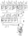
図11は、演出制御基板80、中継基板606,607、盤側IC基板601、枠側IC基板602,603,604,605の構成例を示すブロック図である。演出制御基板80の演出制御用マイクロコンピュータ100は、制御信号としてのシリアルデータとともに、クロック信号を中継基板607に出力する。また、入力IC620,621に入力信号をラッチさせるための入力取込信号を中継基板606に出力する。   FIG. 11 is a block diagram illustrating a configuration example of the effect control board 80, the relay boards 606 and 607, the board-side IC board 601, and the frame-side IC boards 602, 603, 604, and 605. The effect control microcomputer 100 of the effect control board 80 outputs a clock signal to the relay board 607 together with serial data as a control signal. In addition, an input capture signal for causing the input ICs 620 and 621 to latch the input signal is output to the relay board 606.

中継基板606は、演出制御用マイクロコンピュータ100から入力したシリアルデータおよびクロック信号を、盤側IC基板601に搭載された各シリアル−パラレル変換IC616〜619に供給する。そして、各シリアル−パラレル変換IC616〜619は、入力したシリアルデータをパラレルデータに変換して、遊技盤6に設けられた各ランプのLED125a〜125f,126a〜126f,127a〜127cや、各可動部材のモータ151a,152aに供給する。   The relay board 606 supplies the serial data and the clock signal input from the effect control microcomputer 100 to the serial-parallel conversion ICs 616 to 619 mounted on the board side IC board 601. And each serial-parallel conversion IC616-619 converts the input serial data into parallel data, LED125a-125f of each lamp provided in the game board 6, 126a-126f, 127a-127c, and each movable member To the motors 151a and 152a.

また、中継基板607は、バス型に1系統の配線ルートで中継基板606と接続されており、各シリアル−パラレル変換IC616〜619に接続されるシリアルデータ線300およびクロック信号線301は、盤側IC基板601上でバス形式に接続されている。なお、バス型に接続とは、1つの配線ルートに複数のシリアル−パラレル変換ICまたは中継基板が接続されていることである。   Further, the relay board 607 is connected to the relay board 606 through a single wiring route in a bus type, and the serial data line 300 and the clock signal line 301 connected to each serial-parallel conversion IC 616 to 619 are connected to the board side. It is connected to the bus form on the IC substrate 601. The connection to the bus type means that a plurality of serial-parallel conversion ICs or relay boards are connected to one wiring route.

また、盤側IC基板601に搭載された各シリアル−パラレル変換IC616〜619にはそれぞれ固有のIDがある。この実施の形態では、図11に示すように、IC616のIDは06であり、IC617のIDは07であり、IC618のIDは08であり、IC619のIDは09である。   Each serial-parallel conversion IC 616 to 619 mounted on the board side IC substrate 601 has a unique ID. In this embodiment, as shown in FIG. 11, the ID of IC 616 is 06, the ID of IC 617 is 07, the ID of IC 618 is 08, and the ID of IC 619 is 09.

また、盤側IC基板601には、遊技盤6上に設けられた各可動部材の位置センサの検出信号を入力する入力IC621が搭載されている。この実施の形態では、盤側IC基板601に搭載された入力IC621と演出制御用マイクロコンピュータ100とは、中継基板606を介して入力信号線302、クロック信号線301および入力取込信号線303が接続されており、演出制御用マイクロコンピュータ100は、所定のタイミングで、入力取込信号を中継基板606を介して入力IC621に出力する。すると、入力IC621は、入力取込信号(ラッチ信号)に基づいて各位置センサの検出信号をラッチし、中継基板606を介して演出制御用マイクロコンピュータ100に出力する。この場合、入力IC621は、各位置センサからパラレルに入力した検出信号をシリアルデータに変換して出力する。なお、この実施の形態では、図11に示すように、入力IC621の固有のIDは11である。   In addition, an input IC 621 for inputting a detection signal of a position sensor of each movable member provided on the game board 6 is mounted on the board side IC board 601. In this embodiment, the input IC 621 and the production control microcomputer 100 mounted on the board-side IC board 601 include an input signal line 302, a clock signal line 301, and an input capture signal line 303 via a relay board 606. The presentation control microcomputer 100 is connected and outputs an input capture signal to the input IC 621 via the relay board 606 at a predetermined timing. Then, the input IC 621 latches the detection signal of each position sensor based on the input capture signal (latch signal) and outputs it to the effect control microcomputer 100 via the relay board 606. In this case, the input IC 621 converts the detection signal input in parallel from each position sensor into serial data and outputs it. In this embodiment, the unique ID of the input IC 621 is 11, as shown in FIG.

中継基板607に入力されたシリアルデータおよびクロック信号は、図11に示すように、各枠側IC基板602〜605に搭載された各シリアル−パラレル変換IC611〜615,622に供給される。そして、各シリアル−パラレル変換IC611〜615,622は、入力したシリアルデータをパラレルデータに変換して、遊技枠11に設けられた各ランプのLED281a〜281l,282a〜282f,283a〜283f,82a〜82iに供給する。   As shown in FIG. 11, the serial data and clock signal input to the relay board 607 are supplied to the serial-parallel conversion ICs 611 to 615 and 622 mounted on the frame side IC boards 602 to 605. The serial-parallel conversion ICs 611 to 615 and 622 convert the input serial data into parallel data, and the LEDs 281a to 281l, 282a to 282f, 283a to 283f, 82a to 82a of each lamp provided in the game frame 11. 82i.

また、各シリアル−パラレル変換IC611〜614に接続されるシリアルデータ線およびクロック信号線は、各枠側IC基板602〜604上でバス形式に接続されている。この実施の形態では、図11に示すように、まず、枠側IC基板604のシリアル−パラレル変換IC614に入力され、シリアル−パラレル変換IC614から枠側IC基板602のシリアル−パラレル変換IC611およびシリアル−パラレル変換IC612の順に入力され、さらにシリアル−パラレル変換IC612から枠側IC基板603のシリアル−パラレル変換IC613に入力される。また、シリアル−パラレル変換IC615,622に接続されるシリアルデータ線およびクロック信号線は、中継基板607から直接接続される。   The serial data lines and clock signal lines connected to the serial-parallel conversion ICs 611 to 614 are connected in a bus format on the frame side IC substrates 602 to 604. In this embodiment, as shown in FIG. 11, first, the serial-parallel conversion IC 614 of the frame side IC substrate 604 is input, and the serial-parallel conversion IC 614 and the serial-parallel conversion IC 611 of the frame side IC substrate 602 are serially converted. The signals are input in the order of the parallel conversion IC 612, and further input from the serial-parallel conversion IC 612 to the serial-parallel conversion IC 613 of the frame side IC substrate 603. The serial data lines and clock signal lines connected to the serial-parallel conversion ICs 615 and 622 are directly connected from the relay board 607.

また、各枠側IC基板602〜605に搭載された各シリアル−パラレル変換IC611〜615,622にはそれぞれ固有のIDがある。この実施の形態では、図11に示すように、IC611のIDは01であり、IC612のIDは02であり、IC613のIDは03であり、IC614のIDは04であり、IC615のIDは05であり、IC622のIDは12である。   Each serial-parallel conversion IC 611-615, 622 mounted on each frame side IC substrate 602-605 has a unique ID. In this embodiment, as shown in FIG. 11, the ID of IC 611 is 01, the ID of IC 612 is 02, the ID of IC 613 is 03, the ID of IC 614 is 04, and the ID of IC 615 is 05 And the ID of the IC 622 is 12.

また、枠側IC基板605には、遊技枠11に設けられた操作部811における第1押圧検出器81a〜第4押圧検出器81d、第1回転検出器81e、および、第2回転検出器81fのそれぞれの検出信号を入力する入力IC620が搭載されている。この実施の形態では、枠側IC基板605に搭載された入力IC620と演出制御用マイクロコンピュータ100とは、中継基板606,607を介して入力信号線、クロック信号線および入力取込信号線が接続されており、演出制御用マイクロコンピュータ100は、所定のタイミングで、入力取込信号を中継基板606,607を介して入力IC620に出力する。この場合、演出制御用マイクロコンピュータ100は、入力IC621に入力取込信号を出力するタイミングとは異なるタイミングで、入力取込信号を入力IC620に出力する。すると、入力IC620は、入力取込信号(ラッチ信号)に基づいて第1押圧検出器81a〜第4押圧検出器81d、第1回転検出器81e、および、第2回転検出器81fのそれぞれからの検出信号をラッチし、中継基板606,607を介して演出制御用マイクロコンピュータ100に出力する。この場合、入力IC620は、第1押圧検出器81a〜第4押圧検出器81d、第1回転検出器81e、および、第2回転検出器81fのそれぞれからパラレルに入力した検出信号をシリアルデータに変換して出力する。なお、この実施の形態では、図11に示すように、入力IC620の固有のIDは10である。   Further, the frame side IC substrate 605 includes a first press detector 81a to a fourth press detector 81d, a first rotation detector 81e, and a second rotation detector 81f in the operation unit 811 provided in the game frame 11. The input IC 620 for inputting the respective detection signals is mounted. In this embodiment, an input signal line, a clock signal line, and an input capture signal line are connected to the input IC 620 mounted on the frame side IC board 605 and the production control microcomputer 100 via the relay boards 606 and 607. Thus, the production control microcomputer 100 outputs an input capture signal to the input IC 620 via the relay boards 606 and 607 at a predetermined timing. In this case, the production control microcomputer 100 outputs the input capture signal to the input IC 620 at a timing different from the timing of outputting the input capture signal to the input IC 621. Then, the input IC 620 receives signals from the first pressure detector 81a to the fourth pressure detector 81d, the first rotation detector 81e, and the second rotation detector 81f based on the input capture signal (latch signal). The detection signal is latched and output to the production control microcomputer 100 via the relay boards 606 and 607. In this case, the input IC 620 converts the detection signals input in parallel from each of the first pressure detector 81a to the fourth pressure detector 81d, the first rotation detector 81e, and the second rotation detector 81f into serial data. And output. In this embodiment, the unique ID of the input IC 620 is 10 as shown in FIG.

盤側IC基板601に搭載されたシリアル−パラレル変換IC616〜619と各枠側IC基板602〜605に搭載されたシリアル−パラレル変換IC611〜615,622とは、1系統の配線を介して接続されている。1系統の配線を介して接続とは、具体的には、各中継基板606,607がバス型に接続されているとともに、各シリアル−パラレル変換IC611〜619,622がバス型またはデイジーチェーン型に接続されていることである。なお、この実施の形態では、図11に示すように、各シリアル−パラレル変換IC611〜619,622はバス型に接続されている。このように、この実施の形態では、盤側IC基板601に搭載された各シリアル−パラレル変換IC616〜619と、各枠側IC基板602〜605に搭載された各シリアル−パラレルIC611〜615,622とが、中継基板606,607を介してコネクタを用いて1系統の配線を介して接続されている。そのため、コネクタの着脱を行なうだけで遊技枠11と遊技盤6との配線作業を行なうことができ、遊技枠11と遊技盤6との着脱作業をさらに容易に行なえるようにすることができる。   The serial-parallel conversion ICs 616 to 619 mounted on the panel-side IC substrate 601 and the serial-parallel conversion ICs 611 to 615 and 622 mounted on the frame-side IC substrates 602 to 605 are connected through one system wiring. ing. Specifically, the connection through one system of wiring means that the relay boards 606 and 607 are connected in a bus type, and the serial-parallel conversion ICs 611 to 619 and 622 are in a bus type or a daisy chain type. Is connected. In this embodiment, as shown in FIG. 11, the serial-parallel conversion ICs 611 to 619 and 622 are connected in a bus type. As described above, in this embodiment, the serial-parallel conversion ICs 616 to 619 mounted on the board side IC substrate 601 and the serial-parallel ICs 611 to 615 and 622 mounted on the frame side IC substrates 602 to 605 are provided. Are connected through one line of wiring using connectors via relay boards 606 and 607. Therefore, the wiring work between the game frame 11 and the game board 6 can be performed only by attaching / detaching the connector, and the work of attaching / detaching the game frame 11 and the game board 6 can be performed more easily.

また、この実施の形態によれば、盤側IC基板601に搭載されたシリアル−パラレル変換IC616〜619、枠側IC基板602〜605に搭載されたシリアル−パラレル変換IC611〜615,622および入力IC620,621に、演出制御用マイクロコンピュータ100から共通のクロック信号を入力する。そのため、シリアル−パラレル変換IC611〜619,622へのクロック信号の配線と入力IC620,621へのクロック信号の配線とを共通化することができ、演出制御手段と盤側IC601基板との間の通信、および演出制御手段と枠側IC基板602〜605との間の通信を、それぞれ1チャネルを用いて実現することができ、配線数を低減することができる。また、盤側IC基板601に搭載されたシリアル−パラレル変換IC616〜619、枠側IC基板602〜605に搭載されたシリアル−パラレル変換IC611〜615,622、および入力IC620,621とを容易に同期させることができ、クロック信号用の配線数も低減することができる。   Further, according to this embodiment, the serial-parallel conversion ICs 616 to 619 mounted on the board side IC substrate 601, the serial-parallel conversion ICs 611 to 615 and 622 mounted on the frame side IC substrates 602 to 605, and the input IC 620. , 621, a common clock signal is input from the production control microcomputer 100. Therefore, the wiring of the clock signal to the serial-parallel conversion ICs 611 to 619 and 622 and the wiring of the clock signal to the input ICs 620 and 621 can be shared, and communication between the effect control means and the board-side IC 601 board. And communication between the production control means and the frame side IC substrates 602 to 605 can be realized using one channel, respectively, and the number of wirings can be reduced. Also, the serial-parallel conversion ICs 616 to 619 mounted on the board side IC substrate 601, the serial-parallel conversion ICs 611 to 615 and 622 mounted on the frame side IC substrates 602 to 605, and the input ICs 620 and 621 are easily synchronized. The number of clock signal wirings can also be reduced.

この実施の形態では、各シリアル−パラレル変換IC611〜619,622には、予めアドレスが付与されており、演出制御用マイクロコンピュータ100は、シリアルデータに変換した制御信号を出力する際に、シリアルデータにアドレスを付加して出力する。各シリアル−パラレル変換IC611〜619,622は、シリアルデータを入力すると、入力したシリアルデータに付加されているアドレスが自分のアドレスに合致するか否かを確認し、合致していればパラレルデータに変換して各ランプのLEDに供給する(すなわち、出力する)。アドレスが合致していなければ各ランプのLEDへの供給は行なわない。   In this embodiment, the serial-parallel conversion ICs 611 to 619 and 622 are assigned addresses in advance, and the production control microcomputer 100 outputs serial data when outputting the control signal converted into serial data. Appends an address to the output. When each serial-parallel conversion IC 611 to 619 and 622 inputs serial data, the serial-parallel conversion ICs 611 to 619 and 622 check whether or not the address added to the input serial data matches their own address. Convert and supply (i.e., output) the LED of each lamp. If the addresses do not match, the LED of each lamp is not supplied.

なお、図11に示すように、演出制御用マイクロコンピュータ100は、盤側IC基板601および枠側IC基板602〜605と双方向通信を行なう(具体的には、シリアルデータを各シリアル−パラレル変換IC611〜619,622に送信し、入力信号を入力IC620,621から入力する)ものであるので、データ入力端子とデータ出力端子とを備えており、1チャネルでデータ入力とデータ出力とを行なうことができる。この実施の形態では、図11に示すように、1つのチャネルのデータ入力端子とデータ出力端子とを、それぞれ異なる出力対象機器(本例では、シリアル−パラレル変換IC611〜619,622)と入力対象機器(本例では、入力IC620,621)とに接続している。そのように構成することによって、本来、出力対象機器と入力対象機器とが別の機器である場合にはそれぞれ別のチャネルを用いて通信を行なうべきところを、1つのチャネルのみを用いて双方向通信を可能としており、演出制御用マイクロコンピュータ100と盤側IC基板601および枠側IC基板602〜605との間のチャネル数を低減している。   As shown in FIG. 11, the production control microcomputer 100 performs bidirectional communication with the board-side IC board 601 and the frame-side IC boards 602 to 605 (specifically, serial data is converted into serial-parallel data). IC 611 to 619 and 622, and input signals are input from the input ICs 620 and 621). Therefore, a data input terminal and a data output terminal are provided, and data input and data output are performed in one channel. Can do. In this embodiment, as shown in FIG. 11, a data input terminal and a data output terminal of one channel are respectively connected to different output target devices (in this example, serial-parallel conversion ICs 611 to 619, 622) and input targets. It is connected to a device (in this example, input ICs 620 and 621). With such a configuration, when the output target device and the input target device are originally different devices, communication should be performed using different channels in both directions. Communication is enabled, and the number of channels between the production control microcomputer 100, the board side IC substrate 601 and the frame side IC substrates 602 to 605 is reduced.

この実施の形態において、チャネルとは、データ線(出力データ線)、クロック信号線、入力信号線(入力データ線)、および入力取込信号線(入力データの読出要求の信号線)用の端子をセットにしたものである。なお、1つのチャネルにアース線や電源専用の端子を含んでもよい。また、この実施の形態では、1チャネルを用いてデータ入力とデータ出力の両方を行なう場合を示すが、データ線(出力データ線)およびクロック信号線用の端子のみをセットにした出力専用のチャネルを用いてもよい。また、入力信号線(入力データ線)および入力取込信号線(入力データの読出要求の信号線)用の端子のみをセットにした入力専用のチャネルを用いてもよい。   In this embodiment, the channel is a terminal for a data line (output data line), a clock signal line, an input signal line (input data line), and an input take-in signal line (signal line for input data read request). Is a set. One channel may include a ground wire or a terminal dedicated to the power source. Further, in this embodiment, a case where both data input and data output are performed using one channel is shown, but an output-dedicated channel in which only a terminal for a data line (output data line) and a clock signal line is set. May be used. Alternatively, an input-only channel in which only terminals for input signal lines (input data lines) and input take-in signal lines (input data read request signal lines) are set may be used.

図12および図13は、各シリアル−パラレル変換IC611〜619,622に付与されるアドレスの例を示す説明図である。この実施の形態では、演出制御用マイクロコンピュータ100は、予めRAMに設けられた所定のアドレス記憶領域に、図12および図13に示す各シリアル−パラレル変換IC611〜619,622のアドレスを記憶している。   12 and 13 are explanatory diagrams showing examples of addresses given to the serial-parallel conversion ICs 611 to 619 and 622. FIG. In this embodiment, the production control microcomputer 100 stores the addresses of the serial-parallel conversion ICs 611 to 619 and 622 shown in FIGS. 12 and 13 in a predetermined address storage area previously provided in the RAM. Yes.

この実施の形態では、図12および図13に示すように、各枠側IC基板602〜605に搭載されたシリアル−パラレル変換IC611〜615,622において、IC611にはアドレス01が付与され、IC612にはアドレス02が付与され、IC613にはアドレス03が付与され、IC614にはアドレス04が付与され、IC615にはアドレス05が付与され、IC622にはアドレス12が付与されている。また、盤側IC基板601に搭載されたシリアル−パラレル変換IC616〜619において、IC616にはアドレス06が付与され、IC617にはアドレス07が付与され、IC618にはアドレス08が付与され、IC619にはアドレス09が付与されている。   In this embodiment, as shown in FIGS. 12 and 13, in the serial-parallel conversion ICs 611 to 615 and 622 mounted on the frame side IC substrates 602 to 605, an address 01 is given to the IC 611, and the IC 612 is assigned to the IC 612. Is given address 02, IC 613 is given address 03, IC 614 is given address 04, IC 615 is given address 05, and IC 622 is given address 12. Further, in the serial-parallel conversion ICs 616 to 619 mounted on the board side IC substrate 601, the address 006 is given to the IC 616, the address 07 is given to the IC 617, the address 08 is given to the IC 618, and the IC 619 is given to the IC 619. Address 09 is given.

なお、各シリアル−パラレル変換IC611〜619,622には、アドレスとしてICの固有のIDと同じものを付与してもよく、ICの固有のIDとは異なる数字や文字、記号を含むアドレスを付与してもよい。   The serial-parallel conversion ICs 611 to 619 and 622 may have the same ID as the unique ID of the IC as an address, or an address including numbers, characters, and symbols different from the unique ID of the IC. May be.

また、図12および図13に示すように、アドレスが01であるシリアル−パラレル変換IC611は、シリアルデータをパラレルデータに変換し、遊技枠11の天枠ランプのLED(本例では天枠ランプ281a〜281lのうちのLED6個(281a〜281f))に供給する。また、アドレスが02であるシリアル−パラレル変換IC612は、シリアルデータをパラレルデータに変換し、遊技枠11の天枠ランプのLED(本例では天枠ランプ281a〜281lの他のLED6個(281g〜281l))に供給する。また、アドレスが03であるシリアル−パラレル変換IC613は、シリアルデータをパラレルデータに変換し、遊技枠11の右枠ランプのLED(本例ではLED6個(283a〜283f))に供給する。また、アドレスが04であるシリアル−パラレル変換IC614は、シリアルデータをパラレルデータに変換し、遊技枠11の左枠ランプのLED(本例ではLED6個(282a〜282f))に供給する。   As shown in FIGS. 12 and 13, the serial-parallel conversion IC 611 whose address is 01 converts serial data into parallel data, and the LED of the top frame lamp of the game frame 11 (the top frame lamp 281a in this example). To 6 LEDs (281a to 281f) of .about.281l. The serial-parallel conversion IC 612 whose address is 02 converts the serial data into parallel data, and the LED of the ceiling frame lamp of the game frame 11 (in this example, the other six LEDs (281g to 281g to 280g). 281 l)). The serial-parallel conversion IC 613 whose address is 03 converts the serial data into parallel data and supplies the parallel data to the LEDs of the right frame lamp of the game frame 11 (in this example, 6 LEDs (283a to 283f)). Further, the serial-parallel conversion IC 614 whose address is 04 converts the serial data into parallel data, and supplies it to the LED of the left frame lamp of the game frame 11 (in this example, 6 LEDs (282a to 282f)).

また、アドレスが05であるシリアル−パラレル変換IC615は、シリアルデータをパラレルデータに変換し、操作部81に設けられた第1操作部ランプ82a〜第5操作部ランプ82e(本例ではLED5個)に供給する。また、アドレスが12であるシリアル−パラレル変換IC622は、シリアルデータをパラレルデータに変換し、操作部81に設けられた第6操作部ランプ82f〜第9操作部ランプ82i(本例ではLED4個)に供給する。   A serial-parallel conversion IC 615 whose address is 05 converts serial data into parallel data, and a first operation unit lamp 82a to a fifth operation unit lamp 82e provided in the operation unit 81 (5 LEDs in this example). To supply. Further, the serial-parallel conversion IC 622 whose address is 12 converts serial data into parallel data, and operates from a sixth operation unit lamp 82f to a ninth operation unit lamp 82i provided in the operation unit 81 (four LEDs in this example). To supply.

また、アドレスが06であるシリアル−パラレル変換IC616は、シリアルデータをパラレルデータに変換し、遊技盤6に設けられた各可動部材(本例では、梁およびトロッコの形状を模した役物)を駆動するためのモータ(本例ではモータ2個(151a,152a)のそれぞれ正方向と逆方向)に供給する。また、アドレスが07であるシリアル−パラレル変換IC617は、シリアルデータをパラレルデータに変換し、遊技盤6中央に設けられた装飾用構造物(センター飾り)の各ランプ(本例ではLED6個(125a〜125f))に供給する。また、アドレスが08であるシリアル−パラレル変換IC618は、シリアルデータをパラレルデータに変換し、変動表示装置9の周囲に設けられた各ステージランプ(本例ではLED6個(126a〜126f))に供給する。また、アドレスが09であるシリアル−パラレル変換IC619は、シリアルデータをパラレルデータに変換し、可動部材(本例では可変入賞球装置15)周辺に設けられたランプのLED(本例ではLED3個(127a〜127c))に供給する。   The serial-parallel conversion IC 616 whose address is 06 converts serial data into parallel data, and each movable member provided in the game board 6 (in this example, a role imitating the shape of a beam and a truck). It is supplied to a motor for driving (in this example, two motors (151a, 152a) are each in the opposite direction to the forward direction). The serial-parallel conversion IC 617 whose address is 07 converts serial data into parallel data, and each lamp of the decorative structure (center decoration) provided in the center of the game board 6 (in this example, six LEDs (125a To 125 f)). The serial-parallel conversion IC 618 whose address is 08 converts the serial data into parallel data, and supplies it to each stage lamp (in this example, 6 LEDs (126a to 126f)) provided around the variable display device 9. To do. Further, the serial-parallel conversion IC 619 whose address is 09 converts serial data into parallel data, and the lamp LED (three LEDs (in this example) (in this example) provided around the movable member (variable winning ball device 15 in this example). 127a-127c)).

また、この実施の形態では、各入力IC620,621にも、予めアドレスが付与されている。図14は、各入力IC620,621に付与されるアドレスの例を示す説明図である。そして、演出制御用マイクロコンピュータ100は、予めRAMに設けられた所定のアドレス記憶領域に、各入力IC620,621のアドレスを記憶している。この実施の形態では、図14に示すように、枠側IC基板605に搭載された入力IC620にはアドレス10が付与され、盤側IC基板601に搭載された入力IC621にはアドレス11が付与されている。   In this embodiment, the input ICs 620 and 621 are also given addresses in advance. FIG. 14 is an explanatory diagram showing an example of addresses given to the input ICs 620 and 621. The production control microcomputer 100 stores the addresses of the input ICs 620 and 621 in a predetermined address storage area previously provided in the RAM. In this embodiment, as shown in FIG. 14, the address 10 is assigned to the input IC 620 mounted on the frame side IC board 605, and the address 11 is assigned to the input IC 621 mounted on the board side IC board 601. ing.

なお、各入力IC620,621に、アドレスとしては、ICの固有のIDと同じものを付与してもよく、ICの固有のIDとは異なる数字や文字、記号を含むアドレスを付与してもよい。   The input ICs 620 and 621 may be given the same address as the unique ID of the IC, or may be given an address including numbers, characters, and symbols different from the unique ID of the IC. .

また、図14に示すように、アドレスが10である入力IC620は、遊技枠11に設けられた第1押圧検出器81a〜第4押圧検出器81dの検出信号をパラレルで入力し、シリアルデータに変換して出力する。また、アドレスが11である入力IC621は、遊技盤6の各可動部材に設けられた位置センサ151b,152b(本例では2)の検出信号をパラレルで入力し、シリアルデータに変換して出力する。   Further, as shown in FIG. 14, the input IC 620 whose address is 10 inputs the detection signals of the first press detector 81a to the fourth press detector 81d provided in the game frame 11 in parallel and converts them into serial data. Convert and output. Further, the input IC 621 whose address is 11 inputs the detection signals of the position sensors 151b and 152b (2 in this example) provided on each movable member of the game board 6 in parallel, converts them into serial data, and outputs them. .

図15は、各シリアル−パラレル変換IC611〜619,622の構成を示すブロック図である。図15に示すように、シリアル−パラレル変換IC611〜619,622は、データラッチ部651、シフトレジスタ652、ヘッダ/アドレス検出部653、データバッファ655およびシンクドライバ656を含む。   FIG. 15 is a block diagram showing the configuration of each serial-parallel conversion IC 611-619,622. As illustrated in FIG. 15, the serial-parallel conversion ICs 611 to 619 and 622 include a data latch unit 651, a shift register 652, a header / address detection unit 653, a data buffer 655, and a sync driver 656.

データラッチ部651は、たとえばラッチ回路によって構成され、シリアルデータが入力されると、クロック信号のパルスの立ち上がりのタイミングで入力データを1ビット毎にラッチし、シフトレジスタ652に出力する。シフトレジスタ652は、データラッチ部651から1ビットずつ入力されたデータを順に格納する。また、シフトレジスタ652は、クロック信号のパルスの立ち上がりのタイミングで、格納データを1ビットずつシフトする。そのように繰り返し格納データを1ビットずつシフトしていくことによって、最終的にシフトレジスタ652にシリアルデータとして(すなわち、シリアル方式で)入力したデータが格納されることになる。   The data latch unit 651 is configured by, for example, a latch circuit, and when serial data is input, the input data is latched bit by bit at the rising edge of the clock signal pulse and output to the shift register 652. The shift register 652 sequentially stores data input bit by bit from the data latch unit 651. The shift register 652 shifts stored data bit by bit at the rising timing of the pulse of the clock signal. By repeatedly shifting the stored data bit by bit as described above, the data finally input as serial data (that is, in a serial manner) is stored in the shift register 652.

図16は、演出制御用マイクロコンピュータ100から出力されるシリアルデータのフォーマットの例を示す説明図である。図16(A)は、遊技盤6や遊技枠11に設けられた各ランプのLEDを個別に点灯または消灯させるためのランプ点灯データとして出力されるシリアルデータのデータフォーマットである。また、図16(B)は、遊技盤6や遊技枠11に設けられた各ランプのLEDをリセットして全て消灯させるためのリセットコマンドとして出力されるシリアルデータのフォーマットである。   FIG. 16 is an explanatory diagram showing an example of the format of serial data output from the production control microcomputer 100. FIG. 16A shows a data format of serial data output as lamp lighting data for individually lighting or extinguishing the LEDs of each lamp provided in the game board 6 or the game frame 11. FIG. 16B shows a serial data format that is output as a reset command for resetting the LEDs of the respective lamps provided on the game board 6 and the game frame 11 to turn them all off.

図16(A)に示すように、ランプ点灯データは、28ビットで構成され、9ビットのヘッダデータ、マークビット(M)、8ビットのアドレス、8ビットのデータおよびエンドビット(E)を含む。   As shown in FIG. 16A, the lamp lighting data is composed of 28 bits, and includes 9-bit header data, mark bits (M), 8-bit addresses, 8-bit data, and end bits (E). .

ヘッダデータは、データの先頭を表すものであり、本例では1FF(h)である。マークビット(M)は、データの区切りを表すビット(本例では論理値0)であり、ヘッダデータとアドレスとの間、およびアドレスとデータとの間にそれぞれ挿入される。アドレスは、データ出力先のシリアル−パラレル変換ICのアドレスである。なお、アドレスとして、各シリアル−パラレル変換IC611〜619,622の固有の通し番号であるIDを用いてもよい。   The header data represents the head of the data, and is 1FF (h) in this example. The mark bit (M) is a bit (logical value 0 in this example) representing a data delimiter, and is inserted between the header data and the address and between the address and the data. The address is the address of the data-output destination serial-parallel conversion IC. Note that an ID that is a unique serial number of each of the serial-parallel conversion ICs 611 to 619 and 622 may be used as the address.

データ(8ビット)は、各ランプのLEDの点灯状態を制御するためのものであり、たとえば、点灯対象のランプのLEDに対応するビットとして論理値1を含み、非点灯対象のランプのLEDに対応するビットとして論理値0を含む。エンドビット(E)は、データの終了を示すものであり、本例では論理値0である。   The data (8 bits) is for controlling the lighting state of the LED of each lamp, and includes, for example, a logical value 1 as a bit corresponding to the LED of the lamp to be lit, Corresponding bits contain the logical value 0. The end bit (E) indicates the end of data, and has a logical value of 0 in this example.

図16(B)に示すように、リセットコマンドは、19ビットで構成され、9ビットのヘッダデータ、マークビット(M)、8ビットのリセットデータおよびエンドビット(E)を含む。   As shown in FIG. 16B, the reset command is composed of 19 bits and includes 9-bit header data, mark bits (M), 8-bit reset data, and end bits (E).

ヘッダデータは、データの先頭を表すものであり、本例では1FF(h)である。マークビット(M)は、データの区切りを表すビット(本例では論理値0)であり、ヘッダデータとリセットデータとの間に挿入される。リセットデータは、各ランプのLEDの点灯状態をリセットして全て消灯させるためのものであり、たとえば、全て論路値1を含むデータである。エンドビット(E)は、データの終了を示すものであり、本例では論理値0である。   The header data represents the head of the data, and is 1FF (h) in this example. The mark bit (M) is a bit (logical value 0 in this example) representing a data delimiter, and is inserted between the header data and the reset data. The reset data is for resetting the lighting states of the LEDs of the respective lamps so that all the lamps are extinguished. The end bit (E) indicates the end of data, and has a logical value of 0 in this example.

この実施の形態では、図16(A)に示すランプ点灯データまたは図16(B)に示すリセットコマンドが入力され、クロック信号のパルスの立ち上がりのタイミングで、ビット単位で繰り返しシフトされてシフトレジスタ652に格納されることになる。   In this embodiment, the lamp lighting data shown in FIG. 16A or the reset command shown in FIG. 16B is input, and the shift register 652 is repeatedly shifted bit by bit at the rising timing of the pulse of the clock signal. Will be stored.

ヘッダ/アドレス検出部653は、シフトレジスタ652の格納データからヘッダおよびアドレスを検出する。まず、ヘッダ/アドレス検出部653は、シフトレジスタ652からのデータを常時検出し、検出したデータの内容がヘッダデータに相当する1FF(h)と一致するか否かを確認する。ヘッダデータ(1FF(h))と一致すれば、そのヘッダデータと一致した箇所をデータの先頭と判断し、シフトレジスタ652に1セットのランプ点灯データまたはリセットコマンドが格納されたと判断する。次いで、ヘッダ/アドレス検出部653は、シフトレジスタ652からアドレスに相当する先頭から11ビット目〜18ビット目のデータを検出し、そのシリアル−パラレル変換ICに予め付与されたアドレスと一致するか否かを確認する。盤側IC基板601および各枠側IC基板602〜605には、たとえば、それぞれ搭載するシリアル−パラレル変換ICのアドレスを格納したアドレス格納レジスタ654が設けられており、ヘッダ/アドレス検出部653は、シフトレジスタ652から検出したアドレスが、予めアドレス格納レジスタ654に格納するアドレスと一致するか否かを確認すればよい。アドレスが一致すれば、ヘッダ/アドレス検出653は、そのシリアル−パラレル変換ICを宛先とするデータを入力したと判定し、入力取込信号(ラッチ信号)をデータバッファ655に出力する。アドレスが一致しなければ、ヘッダ/アドレス検出653は、入力取込信号をデータバッファ655に出力しない。すなわち、この場合、そのシリアル−パラレル変換ICを宛先とするデータではないので、シフトレジスタ652に格納したデータをデータバッファ655に出力することなく、そのまま破棄することになる。   The header / address detector 653 detects the header and address from the data stored in the shift register 652. First, the header / address detection unit 653 constantly detects data from the shift register 652, and confirms whether or not the content of the detected data matches 1FF (h) corresponding to the header data. If it matches the header data (1FF (h)), it is determined that the position that matches the header data is the head of the data, and it is determined that one set of lamp lighting data or reset command is stored in the shift register 652. Next, the header / address detection unit 653 detects the 11th to 18th bit data from the head corresponding to the address from the shift register 652, and whether or not it matches the address previously given to the serial-parallel conversion IC. To check. The board side IC substrate 601 and each frame side IC substrate 602 to 605 are provided with, for example, an address storage register 654 that stores the address of the serial-parallel conversion IC to be mounted, and the header / address detector 653 What is necessary is just to confirm whether or not the address detected from the shift register 652 matches the address stored in the address storage register 654 in advance. If the addresses match, the header / address detection 653 determines that data destined for the serial-parallel conversion IC has been input, and outputs an input capture signal (latch signal) to the data buffer 655. If the addresses do not match, the header / address detection 653 does not output the input capture signal to the data buffer 655. That is, in this case, since the data is not destined for the serial-parallel conversion IC, the data stored in the shift register 652 is discarded without being output to the data buffer 655.

なお、図15では、盤側IC基板601および各枠側IC基板602〜605に予めアドレス格納レジスタ654が設けられている場合を示しているが、アドレス格納レジスタ654に代えて、シリアル−パラレル変換ICに設けられているアドレス端子(8端子(8ビットのアドレスの各ビットにそれぞれ対応する))を介して、外部のハードウェア回路(たとえば、演出制御基板80が搭載する回路)からアドレスを入力するようにしてもよい。そして、外部のハードウェア回路側から、各アドレス端子の入力をHighレベル(以下、Hレベルと呼ぶ)またはLowレベル(以下、Lレベルと呼ぶ)に制御することによって、シリアル−パラレル変換ICにアドレスを入力してもよい。この場合、たとえば、外部のハードウェア回路は、アドレスのいずれかのビットに対応する端子に電圧をかけることによってその端子に対する入力をHレベルとし、またはグランドにスイッチングすることによってその端子に対する入力をLレベルとするように制御する。   15 shows a case where the address storage register 654 is provided in advance on the board side IC substrate 601 and each of the frame side IC substrates 602 to 605. However, instead of the address storage register 654, serial-parallel conversion is shown. An address is input from an external hardware circuit (for example, a circuit mounted on the production control board 80) via an address terminal (8 terminals (corresponding to each bit of an 8-bit address)) provided in the IC. You may make it do. Then, by controlling the input of each address terminal to the high level (hereinafter referred to as H level) or the low level (hereinafter referred to as L level) from the external hardware circuit side, the serial-parallel conversion IC is addressed. May be entered. In this case, for example, the external hardware circuit sets the input to the terminal to H level by applying a voltage to the terminal corresponding to any bit of the address, or sets the input to the terminal to L by switching to the ground. Control to level.

データバッファ655は、たとえば、ラッチレジスタによって構成され、ヘッダ/アドレス検出部653から入力取込信号を入力すると、シフトレジスタ652からデータ部分に相当する先頭から20ビット目〜27ビット目のデータを取り込んでラッチする。そして、データバッファ655は、取り込んだデータをパラレルデータ(Q0〜Q7)として各ランプのLEDに供給(すなわち、出力)することになる。   The data buffer 655 is constituted by, for example, a latch register. When an input capture signal is input from the header / address detection unit 653, the data of the 20th to 27th bits from the head corresponding to the data portion is captured from the shift register 652. Latch with. The data buffer 655 supplies (that is, outputs) the fetched data as parallel data (Q0 to Q7) to the LED of each lamp.

なお、シフトレジスタ652が格納したデータがリセットコマンドであった場合には、先頭から11ビット目〜18ビット目が全て論理値1のデータを格納することになる。この場合、データバッファ655は全ての論理値が1であるデータを取り込んだ場合にはリセットコマンドを入力したと判断し、全てのランプのLEDがリセットされ消灯されることになる。   If the data stored in the shift register 652 is a reset command, the 11th to 18th bits from the beginning all store data having a logical value of 1. In this case, the data buffer 655 determines that a reset command has been input when all data having a logical value of 1 is fetched, and the LEDs of all the lamps are reset and turned off.

シンクドライバ656は、所定の論理反転設定信号に基づいて、データバッファ655が出力するパラレルデータの論理値を反転して出力したり、そのまま出力したりする。たとえば、所定の論理反転設定信号がHighである場合には、データバッファ655が出力するパラレルデータのビット値が1である(すなわち、ランプ点灯データの対応するビット値が1)ときにオンとなり、各ランプのLEDにオン信号を出力する。この実施の形態では、予め論理反転設定信号の設定値が盤側IC基板601や各枠側IC基板602〜605に設けられたレジスタ等に設定されており、予め設定された設定値に従って各ランプのLEDにオン信号が出力され、各ランプのLEDが点灯するものとする。   The sync driver 656 inverts and outputs the logical value of the parallel data output from the data buffer 655 based on a predetermined logic inversion setting signal, or outputs it as it is. For example, when the predetermined logic inversion setting signal is High, the signal is turned on when the bit value of the parallel data output from the data buffer 655 is 1 (that is, the corresponding bit value of the lamp lighting data is 1), An ON signal is output to the LED of each lamp. In this embodiment, the set value of the logic inversion setting signal is set in advance in a register or the like provided on the panel side IC substrate 601 or each frame side IC substrate 602-605, and each lamp is set according to the set value set in advance. It is assumed that an ON signal is output to each of the LEDs and the LEDs of each lamp are lit.

図17は、シリアル−パラレル変換ICへのシリアルデータおよびクロック信号の入力タイミングと、パラレルデータの出力タイミングとの例を示すタイミング図である。なお、図17では、シリアルデータ方式としてランプ点灯データを入力する場合を説明する。図17に示すように、シリアルデータは、ヘッダデータ、マークビット、アドレス、マークビット、データ、エンドビットの順に、シリアル−パラレル変換ICのシフトレジスタ652に1ビット単位で入力される。そして、この一連のデータを1セットとする。1セットのシリアルデータ(本例ではランプ点灯データ)が全て入力され終わるまで、ヘッダ/アドレス検出部653ではヘッダデータが検出されないので、データバッファ655の出力は変化しない。そのため、シリアル−パラレル変換ICからは、前回受信したシリアルデータに基づく点灯パターンがそのままパラレルデータ方式として出力されている。   FIG. 17 is a timing diagram showing an example of the input timing of serial data and clock signals to the serial-parallel conversion IC and the output timing of parallel data. In FIG. 17, a case where lamp lighting data is input as a serial data method will be described. As shown in FIG. 17, the serial data is input to the shift register 652 of the serial-parallel conversion IC in units of 1 bit in the order of header data, mark bits, addresses, mark bits, data, and end bits. The series of data is set as one set. The header / address detection unit 653 does not detect header data until one set of serial data (in this example, lamp lighting data) is completely input, so the output of the data buffer 655 does not change. Therefore, the lighting pattern based on the serial data received last time is output as it is as a parallel data system from the serial-parallel conversion IC.

1セットのシリアルデータが全て入力され終わると、シフトレジスタ652の格納データからデータ部分がデータバッファ655にラッチされ、新たに受信したシリアルデータに基づく点灯パターンがパラレルデータ方式として出力される。なお、この実施の形態では、図17に示すように、シリアル−パラレル変換ICが出力するパラレルデータのうち、Q0,Q4は、シリアルデータ入力完了後の次のクロック信号のパルスの立ち上がりのタイミングで、直ちに新たな点灯パターンのデータに切り替わる。また、Q1,Q5は、Q0,Q4より1クロック分遅れて新たな点灯パターンのデータに切り替わる。また、Q2,Q6は、Q0,Q4より2クロック分遅れて新たな点灯パターンのデータに切り替わる。さらに、Q3,Q7は、Q0,Q4より3クロック分遅れて新たな点灯パターンのデータに切り替わる。   When all sets of serial data have been input, the data portion from the data stored in the shift register 652 is latched in the data buffer 655, and a lighting pattern based on the newly received serial data is output as a parallel data system. In this embodiment, as shown in FIG. 17, among the parallel data output from the serial-parallel conversion IC, Q0 and Q4 are the rising timing of the pulse of the next clock signal after completion of the serial data input. Immediately, the data is switched to new lighting pattern data. Q1 and Q5 are switched to new lighting pattern data with a delay of one clock from Q0 and Q4. Q2 and Q6 are switched to new lighting pattern data with a delay of two clocks from Q0 and Q4. Further, Q3 and Q7 are switched to new lighting pattern data with a delay of three clocks from Q0 and Q4.

図18は、各入力IC620,621の構成を示すブロック図である。図18に示すように、この実施の形態では、各入力IC620,621は、複数(本例では8個)のDフリップフロップ661〜668によって構成される。この実施の形態では、第1押圧検出器81a〜第4押圧検出器81dおよび第1回転検出器81e〜第2回転検出器81fからの検出信号、または、各位置センサ151b,152bからの検出信号が各入力IC620,621にパラレルに入力され、検出信号ごとにいずれかのDフリップフロップ661〜668に入力される。また、各Dフリップフロップ661〜668にはクロック信号が入力され、各Dフリップフロップ661〜668は、クロックの立ち上がりで順次シフト動作を行なう。そして、パラレルに入力した検出信号をシリアルデータに変換して出力することになる。   FIG. 18 is a block diagram illustrating the configuration of each of the input ICs 620 and 621. As shown in FIG. 18, in this embodiment, each input IC 620, 621 is composed of a plurality (eight in this example) of D flip-flops 661-668. In this embodiment, detection signals from the first pressure detector 81a to the fourth pressure detector 81d and the first rotation detector 81e to the second rotation detector 81f, or detection signals from the position sensors 151b and 152b. Are input in parallel to the input ICs 620 and 621, and input to any of the D flip-flops 661 to 668 for each detection signal. A clock signal is input to each of the D flip-flops 661 to 668, and each D flip-flop 661 to 668 sequentially performs a shift operation at the rising edge of the clock. The detection signals input in parallel are converted into serial data and output.

各Dフリップフロップ661〜668には、演出制御用マイクロコンピュータ100から所定のタイミングで入力取込信号(ラッチ信号)が入力される。入力取込信号が入力されると、第1押圧検出器81a〜第4押圧検出器81dおよび第1回転検出器81e,第2回転検出器81f、または、各位置センサ151b,152bから検出信号が、各Dフリップフロップ661〜668にラッチされる。そして、ラッチされた検出信号は、クロックの立ち上がりで順次シフトされ、シリアルデータ方式として出力される。   An input capture signal (latch signal) is input to each of the D flip-flops 661 to 668 from the effect control microcomputer 100 at a predetermined timing. When an input capture signal is input, detection signals are output from the first pressure detector 81a to the fourth pressure detector 81d and the first rotation detector 81e, the second rotation detector 81f, or the position sensors 151b and 152b. The D flip-flops 661 to 668 are latched. The latched detection signal is sequentially shifted at the rising edge of the clock and output as a serial data system.

次に、演出制御用マイクロコンピュータ100において、回転操作部812の回転方向および回転量(回転角度)を第1回転検出器81eおよび第2回転検出器81fの検出信号に基づいて検出する処理について説明する。   Next, in the production control microcomputer 100, processing for detecting the rotation direction and the rotation amount (rotation angle) of the rotation operation unit 812 based on detection signals of the first rotation detector 81e and the second rotation detector 81f will be described. To do.

図19は、回転操作部812の回転操作時における第1回転検出器81eおよび第2回転検出器81fのそれぞれの検出信号を示すタイミングチャートである。図19においては、(a)に回転操作部812の右回転時におけるタイミングチャートが示されており、(b)に回転操作部812の左回転時におけるタイミングチャートが示されている。図中において「L」はLレベルを示し、「H」はHレベルを示している。また、図中において点線で示すタイミングは、第1回転検出器81eおよび第2回転検出器81fのそれぞれの検出信号において、前述のクリック位置となったタイミングを示している。   FIG. 19 is a timing chart showing detection signals of the first rotation detector 81e and the second rotation detector 81f when the rotation operation unit 812 is rotated. FIG. 19A shows a timing chart when the rotation operation unit 812 rotates to the right, and FIG. 19B shows a timing chart when the rotation operation unit 812 rotates to the left. In the figure, “L” indicates the L level, and “H” indicates the H level. In addition, the timing indicated by the dotted line in the figure indicates the timing at which the click position is reached in the detection signals of the first rotation detector 81e and the second rotation detector 81f.

(a)に示すように、右回転時には、第1回転検出器81eの信号レベルおよび第2回転検出器81fの信号レベルは、「L,L」→「H,L」→「H,H」→「L,H」→「L,L」(「第1回転検出器81eの信号レベル,第2回転検出器81fの信号レベル」)というように、4回信号パターンが変化する。また、(b)に示すように、左回転時には、第1回転検出器81eの信号レベルおよび第2回転検出器81fの信号レベルは、「L,H」→「H,H」→「H,L」→「L,L」→「L,H」(「第1回転検出器81eの信号レベル,第2回転検出器81fの信号レベル」)というように、4回信号パターンが変化する。このように、右回転時と、左回転時とでは、第1回転検出器81eの信号レベルおよび第2回転検出器81fの信号レベルの変化のパターンが異なる。これにより、演出制御用マイクロコンピュータ100は、これらの検出信号がどのようなパターンで変化するかを判断する処理を行なうことにより、回転操作部812が左右のどちらの方向に回転操作されたかを判定する。   As shown to (a), at the time of right rotation, the signal level of the 1st rotation detector 81e and the signal level of the 2nd rotation detector 81f are "L, L"-> "H, L"-> "H, H" → “L, H” → “L, L” (“the signal level of the first rotation detector 81e, the signal level of the second rotation detector 81f”) changes the signal pattern four times. Also, as shown in (b), during left rotation, the signal level of the first rotation detector 81e and the signal level of the second rotation detector 81f are changed from “L, H” → “H, H” → “H, The signal pattern changes four times such as “L” → “L, L” → “L, H” (“the signal level of the first rotation detector 81e, the signal level of the second rotation detector 81f”). Thus, the pattern of changes in the signal level of the first rotation detector 81e and the signal level of the second rotation detector 81f is different between the right rotation and the left rotation. Thereby, the production control microcomputer 100 determines in which direction the rotation operation unit 812 is rotated by performing a process of determining in what pattern these detection signals change. To do.

また、(a)に示すように、右回転時には、回転操作部812の回転操作にしたがってクリック位置が変化するときに、カバープレート815における突起部8150の突起8151がダイヤルベース816に連続的に形成された凹凸部において各クリック位置間の中間点にある各凸部の頂点を通過するときに、「H,H」→「L,H」という第1の変化パターンと、「L,L」→「H,L」という第2の変化パターンとの2種類の変化パターンのいずれかが生じる。これにより、演出制御用マイクロコンピュータ100は、右回転時にはこれら2種類の変化パターンが生じたときに、1クリック位置分だけ右方向に回転操作されたと判定する処理を行なう。このような判定を行なう理由は、前述のように、凹部間の凸部の頂点を突起8151が通過すると、逆方向へ回転操作しない限りその突起8151が次の凹部の底部へ誘導されるので、凹部間の凸部の頂点を突起8151が通過した時点で、1クリック分操作の回転操作が行なわれたものと判断することができるからである。ここで、クリック位置は、たとえば、24箇所設けられており、1クリック位置分の回転操作は、回転中心回りの回転角度として15度分だけ回転操作したことになる。   Further, as shown in (a), when the right position is rotated, the protrusion 8151 of the protrusion 8150 on the cover plate 815 is continuously formed on the dial base 816 when the click position changes according to the rotation operation of the rotation operation part 812. The first change pattern “H, H” → “L, H” and “L, L” → One of the two types of change patterns occurs with the second change pattern “H, L”. As a result, the production control microcomputer 100 performs a process of determining that the rotation operation is performed clockwise by one click position when these two types of change patterns occur during the clockwise rotation. The reason for making such a determination is that, as described above, when the projection 8151 passes the apex of the convex portion between the concave portions, the projection 8151 is guided to the bottom of the next concave portion unless it is rotated in the reverse direction. This is because it can be determined that the rotation operation for one click has been performed when the projection 8151 passes through the apex of the convex portion between the concave portions. Here, for example, 24 click positions are provided, and the rotation operation for one click position is the rotation operation of 15 degrees as the rotation angle around the rotation center.

一方、(b)に示すように、左回転時には、回転操作部812の回転操作にしたがってクリック位置が変化するときに、カバープレート815の突起8151がダイヤルベース816に連続的に形成された凹凸部において各クリック位置間の中間点にある各凸部の頂点を通過するときに、「H,H」→「L,H」という第1の変化パターンと、「L,L」→「H,L」という第2の変化パターンとのいずれかが生じる。これにより、演出制御用マイクロコンピュータ100は、左回転時にはこれら2種類の変化パターンが生じたときに、1クリック位置分だけ左方向に回転操作されたと判定する処理を行なう。このような判定を行なう理由は、右回転時の判定理由と同様の理由である。   On the other hand, as shown in (b), when the left position is rotated, the projection 8151 of the cover plate 815 is continuously formed on the dial base 816 when the click position changes according to the rotation operation of the rotation operation unit 812. When passing through the vertices of the convex portions at the intermediate points between the click positions, the first change pattern “H, H” → “L, H” and “L, L” → “H, L” ”Occurs in the second change pattern. As a result, the production control microcomputer 100 performs a process of determining that the leftward rotation is performed by one click position when these two types of change patterns are generated during the left rotation. The reason for making such a determination is the same reason as the determination reason at the time of right rotation.

なお、カバープレート815の突起8151がダイヤルベース816における各凹部の底部に入ったときの信号レベルの変化に基づいて、1クリック位置分だけ回転操作(左右の回転操作で同様)されたと判定するようにしてもよい。たとえば、図19(a)の右回転時には、「H,L」→「L,L」という第1の変化パターンと、「H,L」→「H,H」という第2の変化パターンとの2種類の変化パターンのいずれかが生じるので、このような信号レベルの変化があったときに、1クリック位置分だけ右方向に回転操作されたと判定する。また、図19(b)の左回転時には、「L,L」→「L,H」という第1の変化パターンと、「H,H」→「H,L」という第2の変化パターンとの2種類の変化パターンのいずれかが生じるので、このような信号レベルの変化があったときに、1クリック位置分だけ左方向に回転操作されたと判定する。   It should be noted that, based on the change in the signal level when the projection 8151 of the cover plate 815 enters the bottom of each recess in the dial base 816, it is determined that the rotation operation has been performed by one click position (same for the left and right rotation operations). It may be. For example, during the clockwise rotation of FIG. 19A, a first change pattern “H, L” → “L, L” and a second change pattern “H, L” → “H, H” Since one of the two types of change patterns occurs, it is determined that the rotation operation has been performed clockwise by one click position when such a signal level change occurs. Further, during the left rotation of FIG. 19B, the first change pattern “L, L” → “L, H” and the second change pattern “H, H” → “H, L” Since one of the two types of change patterns occurs, it is determined that the rotation operation has been performed to the left by one click position when such a signal level change occurs.

図20は、演出制御用マイクロコンピュータ100が第1回転検出器81eおよび第2回転検出器81fのそれぞれの検出信号に基づいて回転方向および回転量を判定するために用いられる回転判定テーブルを表形式で示す図である。回転判定テーブルは、演出制御用マイクロコンピュータ100のROMに記憶されており、回転方向および回転量を判定するために読出されて用いられる。   FIG. 20 is a table showing a rotation determination table used for the production control microcomputer 100 to determine the rotation direction and the rotation amount based on the detection signals of the first rotation detector 81e and the second rotation detector 81f. It is a figure shown by. The rotation determination table is stored in the ROM of the production control microcomputer 100, and is read and used to determine the rotation direction and the rotation amount.

演出制御用マイクロコンピュータ100では、所定周期で第1回転検出器81eおよび第2回転検出器81fのそれぞれの検出信号のレベルを確認し、その確認をしたときにおいて、確認後に、今回確認した検出信号のレベルを示す今回判定データを前回判定データとしてRAMに記憶する。そして、新たに検出信号のレベルを確認するごとに、前回判定データを更新していく処理が行なわれる。このように前回判定データを記憶しておくと、前回判定データと今回判定データとの関係に基づいて、前述したような回転方向の判定および回転量の判定を行なうことができる。たとえば、図20に示すように、前回判定データが「H,H」で今回判定データが「L,H」という変化パターンであるときには、回転方向が右回転で回転量が15度であると判定される。同様に、前回判定データが「L,L」で今回判定データが「H,L」という変化パターンであるときには、回転方向が右回転で回転量が15度であると判定される。また、前回判定データが「H,L」で今回判定データが「L,L」という変化パターンであるときには、回転方向が左回転で回転量が15度であると判定される。同様に、前回判定データが「L,H」で今回判定データが「H,H」という変化パターンであるときには、回転方向が左回転で回転量が15度であると判定される。   In the effect control microcomputer 100, the levels of the detection signals of the first rotation detector 81e and the second rotation detector 81f are confirmed at predetermined intervals, and when the confirmation is confirmed, the detection signal confirmed this time is confirmed. The present determination data indicating the level of the above is stored in the RAM as previous determination data. Each time the level of the detection signal is newly confirmed, processing for updating the previous determination data is performed. If the previous determination data is stored in this manner, the determination of the rotation direction and the determination of the rotation amount as described above can be performed based on the relationship between the previous determination data and the current determination data. For example, as shown in FIG. 20, when the previous determination data is a change pattern of “H, H” and the current determination data is “L, H”, it is determined that the rotation direction is right rotation and the rotation amount is 15 degrees. Is done. Similarly, when the previous determination data is “L, L” and the current determination data is a change pattern “H, L”, it is determined that the rotation direction is right rotation and the rotation amount is 15 degrees. When the previous determination data is “H, L” and the current determination data is a change pattern of “L, L”, it is determined that the rotation direction is counterclockwise and the rotation amount is 15 degrees. Similarly, when the previous determination data is “L, H” and the current determination data is a change pattern “H, H”, it is determined that the rotation direction is counterclockwise and the rotation amount is 15 degrees.

その他、前回判定データが「H,L」で今回判定データが「L,L」という変化パターン、前回判定データが「H,L」で今回判定データが「H,H」という変化パターン、前回判定データが「L,L」で今回判定データが「L,H」という変化パターン、および、前回判定データが「H,H」で今回判定データが「H,L」という変化パターンのそれぞれについては、前述したように、カバープレート815の突起8151がダイヤルベース816における各凹部の底部に入ったときの信号レベルの変化であるので、この実施の形態では、前述のような理由により、1クリック位置分だけの回転量、すなわち、回転量が15度であると判定しない。   In addition, a change pattern in which the previous determination data is “H, L” and the current determination data is “L, L”, a change pattern in which the previous determination data is “H, L” and the current determination data is “H, H”, and the previous determination For each of the change pattern in which the data is “L, L” and the current determination data is “L, H” and the change pattern in which the previous determination data is “H, H” and the current determination data is “H, L”, As described above, since the signal level changes when the projection 8151 of the cover plate 815 enters the bottom of each concave portion of the dial base 816, in this embodiment, the amount corresponding to one click position is obtained for the reason described above. Only the rotation amount, that is, the rotation amount is not determined to be 15 degrees.

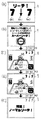
次に、操作部81の操作が要求される時期と、操作部81の操作に応じて変動表示装置において行なわれる表示動作とについて説明する。図21は、演出モードが選択可能なときに変動表示装置9に表示される画像を示す表示画面図である。   Next, the timing when the operation of the operation unit 81 is requested and the display operation performed in the variable display device according to the operation of the operation unit 81 will be described. FIG. 21 is a display screen diagram showing an image displayed on the variable display device 9 when the effect mode can be selected.

このパチンコ遊技機1においては、変動表示装置9において行なわれる演出のうち、飾り図柄の背景画像を表示する演出モードを、予め定められた複数の演出モードから選択可能である。演出モードは、たとえば、演出モードA(たとえば山の演出モード)、演出モードB(たとえば夜空の演出モード)、および、演出モードC(たとえば海の演出モード)という3種類の演出モードが設けられている。パチンコ遊技機1の起動後(電源投入後)の初期状態において、演出モードは、たとえば演出モードAのような3種類の演出モードのうち予め定められた1つの演出モードに選択されており、その後、以下に示すように、操作部81の操作に応じて、遊技者が希望する演出モードに選択する(選択を変更する)ことが可能となる。   In this pachinko gaming machine 1, among the effects performed in the variable display device 9, an effect mode for displaying a background image of a decorative design can be selected from a plurality of predetermined effect modes. There are three types of effect modes, such as effect mode A (for example, mountain effect mode), effect mode B (for example, night sky effect mode), and effect mode C (for example, sea effect mode). Yes. In the initial state after the pachinko gaming machine 1 is started (after power is turned on), the production mode is selected as one of the three production modes such as the production mode A, and thereafter As shown below, according to the operation of the operation unit 81, it is possible to select (change the selection) an effect mode desired by the player.

図20において、(a)では、左,中,右の飾り図柄901,902,903が停止表示されており、その背景画像として演出モードAの背景画像が表示されている状態が示されている。そして、変動表示装置9において飾り図柄の変動表示が行なわれていないときにおいて、押圧操作部811により方向選択操作および決定操作のうちのいずれかの操作が行なわれたという条件が成立すると、(b)のように、演出モードの選択を受付ける旨を示す画像である演出モード選択受付画像が表示される。演出モード選択受付画像においては、演出モードの選択にあたり、どのように操作部81を操作するかを説明する操作案内表示が行なわれる。たとえば、(b)では、回転操作部812を回転操作して演出モードの項目を選択し、押圧操作部811の中央部を押圧操作して演出モードを決定する旨を説明する表示が行なわれている。また、演出モード選択受付画像においては、飾り図柄901,902,903が表示画面における右下の領域で縮小表示されている。   20A, the left, middle, and right decorative symbols 901, 902, and 903 are stopped and displayed, and the background image of the effect mode A is displayed as the background image. . If the condition that any one of the direction selection operation and the determination operation is performed by the pressing operation unit 811 when the decorative display is not displayed on the variable display device 9 is satisfied (b) ), An effect mode selection acceptance image that is an image indicating that the selection of the effect mode is accepted is displayed. In the effect mode selection acceptance image, an operation guidance display for explaining how to operate the operation unit 81 is performed in selecting the effect mode. For example, in (b), a display explaining that the effect mode is determined by selecting the effect mode item by rotating the rotation operation unit 812 and pressing the center part of the pressing operation unit 811 is performed. Yes. In the effect mode selection acceptance image, decorative symbols 901, 902, and 903 are reduced and displayed in the lower right area of the display screen.

演出モード選択受付画像が所定期間表示された後、(c)のように、選択可能な演出モードA〜演出モードCの3つの演出モードを示す画像が表示される。このような画像が表示されているときに、回転操作部812を回転操作すると、その回転操作に応じて選択する演出モードの項目を変更することができる。たとえば、(c)のように選択可能な演出モードはそれぞれの演出モードに対応するアイコン画像904〜906で表示され、現在選択されている演出モードに対応するアイコン画像((c)の場合は904、(d)の場合は905)が、特定の色(以下、選択色という)で表示されることにより、選択されていない演出モードに対応するアイコン画像との関係で識別可能となるように表示される。これにより、選択されている演出モードが特定される。このように、選択されている演出モードを特定する画像を演出モード選択画像という。このように回転操作部812が回転操作されると、(d)のように、その回転操作に応じて、選択色となるアイコン画像が順次変化し、選択する演出モードの項目を変更することができる。(c)の表示が行なわれる初期の段階では、現在選択されているアイコン画像が選択色とされ、その後、回転操作に応じて、選択色とされるアイコン画像が変更される。   After the effect mode selection acceptance image is displayed for a predetermined period, as shown in (c), an image showing three effect modes of effect mode A to effect mode C that can be selected is displayed. When the rotation operation unit 812 is rotated while such an image is displayed, the item of the effect mode to be selected according to the rotation operation can be changed. For example, the selectable effect modes as shown in (c) are displayed as icon images 904 to 906 corresponding to the respective effect modes, and the icon image corresponding to the currently selected effect mode (904 in the case of (c)). In the case of (d), 905) is displayed in a specific color (hereinafter referred to as a selected color) so that it can be identified in relation to an icon image corresponding to an unselected effect mode. Is done. Thereby, the selected production mode is specified. In this way, an image that specifies the selected effect mode is referred to as an effect mode selection image. When the rotation operation unit 812 is rotated in this way, as shown in (d), the icon image to be the selected color is sequentially changed according to the rotation operation, and the item of the effect mode to be selected can be changed. it can. In the initial stage where the display of (c) is performed, the currently selected icon image is set as the selection color, and then the icon image set as the selection color is changed according to the rotation operation.

回転操作部812により左回転の回転操作が行なわれるときは、演出モードA→演出モードB→演出モードC→演出モードA・・・の順で回転操作にしたがって演出モードを選択する表示が行なわれる。また、右回転の回転操作が行なわれるときは、演出モードA→演出モードC→演出モードB→演出モードA・・・の順で回転操作にしたがって演出モードを選択する表示が行なわれる。   When the rotation operation unit 812 performs a left rotation operation, a display for selecting an effect mode is performed in the order of effect mode A → effect mode B → effect mode C → effect mode A. . When a clockwise rotation operation is performed, a display for selecting an effect mode is performed in the order of effect mode A → effect mode C → effect mode B → effect mode A.

そして、押圧操作部811の中央部を押圧操作すると、その押圧操作に応じて、選択されている演出モードが、これから選択する演出モードとして決定され、(d)のように、選択されている演出モードが決定された旨を示すメッセージを表示する演出モード決定画像が表示される。その後、(e)のように、決定された演出モードに対応する、背景画像が表示される。また、演出モードが決定される前の段階で変動表示を開始する条件が成立したときには、演出モードが変更されずに、演出モード受付画像が表示される前に選択されていた演出モードが継続される。なお、また、演出モードが決定される前の段階で変動表示を開始する条件が成立したときには、そのときに演出モード選択画像で選択されている演出モードを新たな演出モードとして選択することを決定するようにしてもよい。   And if the center part of the press operation part 811 is pressed, according to the press operation, the selected production mode will be determined as a production mode to be selected from now on, and the production selected as shown in (d). An effect mode determination image for displaying a message indicating that the mode has been determined is displayed. Thereafter, a background image corresponding to the determined effect mode is displayed as shown in (e). In addition, when the condition for starting the variable display is established at a stage before the production mode is determined, the production mode is not changed, and the production mode selected before the production mode reception image is displayed is continued. The In addition, when the condition for starting the variable display is established at the stage before the production mode is determined, it is decided to select the production mode selected in the production mode selection image at that time as a new production mode. You may make it do.

このような演出モードの選択が可能となる条件は、変動表示装置9において飾り図柄の変動表示が行なわれていないときにおいて、押圧操作部811により方向選択操作および決定操作のうちのいずれかの操作が行なわれたときに成立する。したがって、遊技者は、自らが好む時期に演出モードを変更する可能となることにより、演出モードを変更して気分を変えて遊技を継続することができるようになる。   The condition for enabling selection of such an effect mode is that any one of the direction selection operation and the determination operation is performed by the pressing operation unit 811 when the decorative display is not displayed on the variable display device 9. It is established when Therefore, the player can change the effect mode at a time that he / she likes, and can change the mood by changing the effect mode and continue the game.

このように、遊技者は、操作部81の操作に基づいて、複数種類の演出モードのうちから好みに応じて任意に演出モードを選択することが可能となるので、演出表示の自由度が増し、遊技の興趣を向上させることができる。   As described above, the player can arbitrarily select the effect mode according to his / her preference from a plurality of types of effect modes based on the operation of the operation unit 81, so that the degree of freedom of effect display is increased. , You can improve the fun of the game.

図22および図23のそれぞれは、チャンスリーチと呼ばれる特定種類のリーチとすることが決定されたときに、変動表示装置9に表示される画像を示す表示画面図である。図22には、リーチFの変動パターンでの変動表示が行なわれることによりリーチ表示態様においてスーパーリーチの演出表示が行なわれるときの画像が示され、図23にはリーチEの変動パターンでの変動表示が行なわれることによりリーチ表示態様においてスーパーリーチの演出表示が行なわれないときの画像が示されている。   Each of FIG. 22 and FIG. 23 is a display screen diagram showing an image displayed on the variable display device 9 when it is determined to be a specific type of reach called chance reach. FIG. 22 shows an image when the effect display of the super reach is performed in the reach display mode by performing the change display in the change pattern of the reach F, and FIG. 23 shows the change in the change pattern of the reach E. An image when the super reach effect display is not performed in the reach display mode by the display is shown.

このパチンコ遊技機1においては、変動表示装置9においてリーチ表示態様の演出表示(以下、リーチ演出表示という)が行なわれるときに、操作部81の操作に応じて演出表示が変化する動作表示が行なわれる。   In the pachinko gaming machine 1, when the display of reach display mode (hereinafter referred to as reach display) is performed on the variable display device 9, an operation display in which the display changes according to the operation of the operation unit 81 is performed. It is.

図22および図23の(a)に示すように、中飾り図柄902が変動中において左飾り図柄901と右飾り図柄903とが同じ図柄で停止すると、リーチ状態となり、リーチ演出表示が行なわれる。前述のリーチEおよびリーチFのそれぞれにおいては、リーチ演出表示として、図22および図23の(b)のように、回転操作部812の回転操作を要求するリーチ時回転操作要求画像が表示される。リーチ時回転操作要求画像では、回転操作部812の回転操作に応じて所定の状況を示す画像が表示されればスーパーリーチとなる旨(「回転リングを操作してシュートしてください!シュートが決まればスーパーリーチ!」)を示すことにより、どのように操作部81を操作するかを説明する操作案内表示が行なわれる。   As shown in FIGS. 22 and 23 (a), when the left decorative design 901 and the right decorative design 903 stop at the same design while the center decorative design 902 is changing, the reach state is reached and the reach effect display is performed. In each of the above reach E and reach F, a reach rotation operation request image for requesting the rotation operation of the rotation operation unit 812 is displayed as a reach effect display as shown in FIG. 22 and FIG. . In the reach rotation operation request image, if an image indicating a predetermined situation is displayed in response to the rotation operation of the rotation operation unit 812, it indicates that it will be super reach (“Please operate the rotation ring and shoot! In this case, an operation guidance display for explaining how to operate the operation unit 81 is performed.

そして操作案内表示が所定期間行なわれた後、図22および図23の(c),(d)に示すようなエアホッケーのミニゲームを行なう画像が表示される。その画像が表示されているときに、回転操作部812を回転操作すると、その操作に応じて、図22および図23の(d)に示すように、パック907を打つ打撃道具としてのマレット908が動作する表示(たとえば、回転操作部812の回転操作に応じてマレット908が所定の円周上で動作する表示)が行なわれ、その操作にしたがって、予め定められた時間(たとえば15秒)内で遊技者側(マレット908のみが表示されている側)とパチンコ遊技機1側(キャラクタ909が表示されている側)とでエアホッケーゲームで対戦する形式のミニゲームが行なわれる。   Then, after the operation guidance display is performed for a predetermined period, an image for performing an air hockey mini-game as shown in FIGS. 22 and 23 (c) and (d) is displayed. When the rotation operation unit 812 is rotated while the image is displayed, a mallet 908 as a striking tool for hitting the pack 907 is shown in FIG. 22 and FIG. An operation display (for example, a display in which the mallet 908 operates on a predetermined circumference in accordance with the rotation operation of the rotation operation unit 812) is performed, and within a predetermined time (for example, 15 seconds) according to the operation. A mini game of the type in which the player side (side where only the mallet 908 is displayed) and the pachinko gaming machine 1 side (side where the character 909 is displayed) competes in an air hockey game is performed.

ミニゲームにおいては、(c),(d)に示すように、ゲームの進行に応じて、対戦する両者の得点が表示される(図22の(c)および図23の(c),(d)においては遊技者側が0点でパチンコ遊技機1側が5点、図22の(d)においては遊技者側が1点でパチンコ遊技機1側が5点)とともに、ゲームの残り時間も表示される(図22の(c)および図23の(c)においては7秒、図22の(d)においては3秒、図23の(d)においては0秒)。このようなミニゲームにおいては、所定時間が経過するまでに遊技者側が得点をしたとき(たとえば、図22の(d)のような1得点をしたとき)には、図22の(e)に示すようにスーパーリーチとなった旨が表示された後、(f)に示すように、押圧操作部811の押圧操作を要求するスーパーリーチ時押圧操作要求画像が表示される。リーチFでの変動パターンのときは、このようなミニゲームの状況およびスーパーリーチに関する表示が行なわれるように演出表示内容が予め定められており、図22の(e)のようなスーパーリーチの表示態様となったときに、スーパーリーチの演出表示をする条件が成立する。   In the mini-game, as shown in (c) and (d), as the game progresses, the scores of both players will be displayed ((c) in FIG. 22 and (c) and (d) in FIG. 23. ), The player side has 0 points and the pachinko gaming machine 1 side has 5 points, and in FIG. 22D, the player side has 1 point and the pachinko gaming machine 1 side has 5 points), and the remaining time of the game is also displayed ( 22 (c) and FIG. 23 (c), 7 seconds, FIG. 22 (d) 3 seconds, FIG. 23 (d) 0 seconds). In such a mini game, when the player has scored before the predetermined time elapses (for example, when one score as shown in FIG. 22 (d)), the game is changed to (e) of FIG. After the fact that the super reach has been displayed as shown, a press operation request image at the time of super reach requesting the pressing operation of the pressing operation unit 811 is displayed as shown in (f). In the case of the fluctuation pattern in reach F, the effect display contents are determined in advance so that display regarding the situation of the mini game and the super reach is performed, and the super reach display as shown in FIG. When it becomes a mode, a condition for displaying the effect of super reach is established.

一方、このようなミニゲームにおいては、所定時間が経過するまでに遊技者側が得点をしなかったとき(たとえば、図23の(d)のようなとき)、または、所定時間が経過するまでにパチンコ遊技機1側が得点をしたとき(図示省略)に、図23の(e)に示すようにノーマルリーチとなった旨が表示された後、それ以降、ノーマルリーチとして与えられる演出表示が行なわれる。リーチEでの変動パターンのときは、このようなミニゲーム状況およびノーマルリーチに関する表示が行なわれるように、演出表示内容が予め定められている。   On the other hand, in such a mini game, when the player does not score before the predetermined time elapses (for example, as shown in FIG. 23D), or until the predetermined time elapses. When the pachinko gaming machine 1 scores (not shown), a message indicating that the normal reach has been displayed is displayed as shown in FIG. 23E, and thereafter, an effect display given as the normal reach is performed. In the case of the variation pattern in reach E, the effect display contents are determined in advance so that display regarding such a mini game situation and normal reach is performed.

図22の(f)に示すようなスーパーリーチ時押圧操作要求画像では、押圧操作部811を押圧操作して所定の状況を示す画像を表示する旨(「CHANCEボタンを連打してパワーをためてください!」)を示すことにより、どのように操作部81を操作するかを説明する操作案内表示が行なわれる。   In the press operation request image at the time of super reach as shown in FIG. 22 (f), the pressing operation unit 811 is pressed to display an image indicating a predetermined situation (“CHANCE button is repeatedly pressed to save power. "!") Is displayed, an operation guidance display explaining how to operate the operation unit 81 is performed.

そして操作案内表示が所定期間行なわれた後、図22の(g)に示すように、押圧操作部811の押圧操作回数の増加に応じて、棒グラフ形式で表示されるパワーの値が増加する表示であるチャンス表示が行なわれる。その後、予め定められた期間が経過すると、図22の(h),(i)に示すように、貯まっているパワーに応じて、中飾り図柄の停止図柄を決める演出表示が行なわれる。そして、大当りとすることが決定されているときには、図22の(j)のように大当り表示結果が表示され、一方、はずれとすることが決定されているときには、はずれ表示結果が表示される。図22の(h),(i)に示すような、貯まっているパワーに応じて表示される中飾り図柄の停止図柄を決める演出表示の画像は、貯まっているパワーが多い程、大当り表示結果となることを連想させるような画像にすることが望ましい。   Then, after the operation guidance display is performed for a predetermined period, as shown in (g) of FIG. 22, the power value displayed in the bar graph format increases as the number of pressing operations of the pressing operation unit 811 increases. A chance display is performed. Thereafter, when a predetermined period has elapsed, as shown in FIGS. 22 (h) and (i), an effect display for determining a stop symbol for the center ornament symbol is performed according to the accumulated power. Then, when it is determined to be a big hit, a big hit display result is displayed as shown in (j) of FIG. 22, while when it is determined to be a big hit, a loss display result is displayed. As shown in (h) and (i) of FIG. 22, in the effect display image for determining the stop symbol of the center ornament symbol displayed according to the accumulated power, the larger the accumulated power, the larger the jackpot display result. It is desirable to make the image reminiscent of becoming.

このように、遊技者は、操作部81の操作に基づいて、リーチ表示態様のような演出表示の進行に関与することが可能となるので、遊技の演出態様が多様化し、遊技の興趣を向上させることができる。   As described above, the player can be involved in the progress of the effect display such as the reach display mode based on the operation of the operation unit 81, so that the game effect mode is diversified and the interest of the game is improved. Can be made.

図24は、キャラクタ選択リーチと呼ばれる所定種類のリーチとすることが決定されたときに、変動表示装置9に表示される画像を示す表示画面図である。   FIG. 24 is a display screen diagram showing an image displayed on the variable display device 9 when it is determined to be a predetermined type of reach called character selection reach.

(a)に示すように、リーチ状態となった後、リーチ演出表示として、(b)のように、所定時間(たとえば10秒)内にキャラクタを選択するために押圧操作部811の方向選択操作を要求するリーチ時方向選択操作要求画像が表示される。リーチ時方向選択操作要求画像では、キャラクタの選択にあたり、どのように操作部81を操作するかを説明する操作案内表示が行なわれる。たとえば、(b)では、所定時間内に押圧操作部811により方向選択操作をしてキャラクタの項目を選択する旨を説明する表示が行なわれている。また、リーチ時方向選択操作要求画像においては、飾り図柄901,902,903が表示画面における右上の領域で縮小表示されている。また、キャラクタを選択可能な時間の残り時間が表示画面における右下の領域で表示される。   As shown in (a), after reaching the reach state, as a reach effect display, as shown in (b), a direction selection operation of the pressing operation unit 811 for selecting a character within a predetermined time (for example, 10 seconds). A reach direction selection operation request image for requesting is displayed. In the reach direction selection operation request image, an operation guidance display is provided to explain how to operate the operation unit 81 in selecting a character. For example, in (b), a display explaining that a character item is selected by performing a direction selection operation with the pressing operation unit 811 within a predetermined time is displayed. In the reach direction selection operation request image, decorative symbols 901, 902, and 903 are reduced and displayed in the upper right area of the display screen. Further, the remaining time during which the character can be selected is displayed in the lower right area of the display screen.

リーチ時方向選択操作要求画像においては、選択可能なキャラクタA〜キャラクタDの4つのキャラクタを示す画像が表示される。このような画像が表示されているときに、押圧操作部811により方向選択操作をすると、その方向選択操作に応じて、選択するキャラクタの項目を変更することができる。たとえば、(b)のように選択可能なキャラクタはそれぞれのキャラクタに対応するアイコン画像910〜913で表示され、現在選択されているキャラクタに対応するアイコン画像((b)の場合は910、(c)の場合は913)が、特定の色(以下、選択色という)で表示されることにより、選択されていない演出モードに対応するアイコン画像との関係で識別可能となるように表示される。これにより、選択されているキャラクタが特定される。このように、選択されているキャラクタを特定する画像をキャラクタ選択画像という。   In the reach direction selection operation request image, images indicating four characters A to D that can be selected are displayed. When a direction selection operation is performed by the pressing operation unit 811 while such an image is displayed, the item of the character to be selected can be changed according to the direction selection operation. For example, selectable characters as shown in (b) are displayed as icon images 910 to 913 corresponding to the respective characters, and icon images corresponding to the currently selected character (910 and (c in the case of (b)). ) Is displayed in a specific color (hereinafter referred to as a selected color), so that it can be identified in relation to an icon image corresponding to a non-selected effect mode. Thereby, the selected character is specified. In this manner, an image that identifies the selected character is referred to as a character selection image.

押圧操作部811により方向選択操作がされると、(c)のように、その方向選択操作に応じて、選択色となるアイコン画像が順次変化し、選択するキャラクタの項目を変更することができる。そして、所定の時間が経過すると、その経過時に選択されているキャラクタが、これから選択するキャラクタとして決定され、(c)のように、選択されているキャラクタが決定された旨を示すメッセージを表示するキャラクタ選択決定画像が表示される。その後、(d)のように、決定されたキャラクタCがリーチ演出表示において表示される。   When the direction selection operation is performed by the pressing operation unit 811, as shown in (c), the icon image as the selection color is sequentially changed according to the direction selection operation, and the item of the character to be selected can be changed. . When a predetermined time elapses, the character selected at that time is determined as the character to be selected, and a message indicating that the selected character has been determined is displayed as shown in (c). A character selection decision image is displayed. Thereafter, as shown in (d), the determined character C is displayed in the reach effect display.

このように、遊技者は、操作部81の操作に基づいて、複数種類のキャラクタのうちから好みに応じて任意にキャラクタを選択することが可能となるので、演出表示の自由度が増し、遊技の興趣を向上させることができる。   In this way, the player can arbitrarily select a character from a plurality of types of characters according to his / her preference based on the operation of the operation unit 81, so that the degree of freedom of effect display is increased, and the game Can improve the interest of

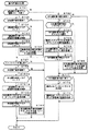
次に、パチンコ遊技機1の動作について説明する。図25は、主基板31における遊技制御用マイクロコンピュータ560が実行するメイン処理を示すフローチャートである。遊技機に対して電源が投入され電力供給が開始されると、リセット信号が入力されるリセット端子の入力レベルがハイレベルになり、遊技制御用マイクロコンピュータ560(具体的には、CPU56)は、プログラムの内容が正当か否か確認するための処理であるセキュリティチェック処理を実行した後、ステップS(以下、単にSという)1以降のメイン処理を開始する。メイン処理において、CPU56は、まず、必要な初期設定を行なう。   Next, the operation of the pachinko gaming machine 1 will be described. FIG. 25 is a flowchart showing a main process executed by the game control microcomputer 560 on the main board 31. When power is supplied to the gaming machine and power supply is started, the input level of the reset terminal to which the reset signal is input becomes high level, and the gaming control microcomputer 560 (specifically, the CPU 56) After executing a security check process, which is a process for confirming whether the contents of the program are valid, the main process after step S (hereinafter simply referred to as S) 1 is started. In the main process, the CPU 56 first performs necessary initial settings.

初期設定処理において、CPU56は、まず、割込禁止に設定する(S1)。次に、割込モードを割込モード2に設定し(S2)、スタックポインタにスタックポインタ指定アドレスを設定する(S3)。そして、内蔵デバイスの初期化(内蔵デバイス(内蔵周辺回路)であるCTC(カウンタ/タイマ)およびPIO(パラレル入出力ポート)の初期化等)を行なった後(S4)、RAMをアクセス可能状態に設定する(S5)。なお、割込モード2は、CPU56が内蔵する特定レジスタ(Iレジスタ)の値(1バイト)と内蔵デバイスが出力する割込ベクタ(1バイト:最下位ビット0)とから合成されるアドレスが、割込番地を示すモードである。   In the initial setting process, the CPU 56 first sets the interrupt prohibition (S1). Next, the interrupt mode is set to interrupt mode 2 (S2), and a stack pointer designation address is set to the stack pointer (S3). Then, after initialization of the built-in device (initialization of the CTC (counter / timer) and PIO (parallel input / output port) which are the built-in device (built-in peripheral circuit)) (S4), the RAM is made accessible. Set (S5). In the interrupt mode 2, the address synthesized from the value (1 byte) of the specific register (I register) built in the CPU 56 and the interrupt vector (1 byte: least significant bit 0) output from the built-in device is This mode indicates an interrupt address.

次いで、CPU56は、入力ポートを介して入力されるクリアスイッチ(たとえば、電源基板に搭載されている。)の出力信号の状態を確認する(S6)。その確認においてオンを検出した場合には、CPU56は、通常の初期化処理を実行する(S10〜S15。S44,S45を含む。)。   Next, the CPU 56 checks the state of the output signal of the clear switch (for example, mounted on the power supply board) input via the input port (S6). When the ON is detected in the confirmation, the CPU 56 executes normal initialization processing (S10 to S15, including S44 and S45).

クリアスイッチがオンの状態でない場合には、遊技機への電力供給が停止したときにバックアップRAM領域のデータ保護処理(たとえばパリティデータの付加等の電力供給停止時処理)が行なわれたか否か確認する(S7)。そのような保護処理が行なわれていないことを確認したら、CPU56は初期化処理を実行する。バックアップRAM領域にバックアップデータがあるか否かは、たとえば、電力供給停止時処理においてバックアップRAM領域に設定されるバックアップフラグの状態によって確認される。   If the clear switch is not on, check whether data protection processing for the backup RAM area (for example, power supply stop processing such as addition of parity data) was performed when power supply to the gaming machine was stopped (S7). If it is confirmed that such a protection process has not been performed, the CPU 56 executes an initialization process. Whether there is backup data in the backup RAM area is confirmed, for example, by the state of the backup flag set in the backup RAM area in the power supply stop process.

電力供給停止時処理が行なわれたことを確認したら、CPU56は、バックアップRAM領域のデータチェックを行なう(S8)。この実施の形態では、データチェックとしてパリティチェックを行なう。よって、S8では、算出したチェックサムと、電力供給停止時処理で同一の処理によって算出され保存されているチェックサムとを比較する。不測の停電等の電力供給停止が生じた後に復旧した場合には、バックアップRAM領域のデータは保存されているはずであるから、チェック結果(比較結果)は正常(一致)になる。チェック結果が正常でないということは、バックアップRAM領域のデータが、電力供給停止時のデータとは異なっていることを意味する。そのような場合には、内部状態を電力供給停止時の状態に戻すことができないので、電力供給の停止からの復旧時でない電源投入時に実行される初期化処理を実行する。   If it is confirmed that the power supply stop process has been performed, the CPU 56 checks the data in the backup RAM area (S8). In this embodiment, a parity check is performed as a data check. Therefore, in S8, the calculated checksum is compared with the checksum calculated and stored by the same process in the power supply stop process. When the power supply is stopped after an unexpected power failure or the like, the data in the backup RAM area should be saved, so the check result (comparison result) is normal (matched). That the check result is not normal means that the data in the backup RAM area is different from the data when the power supply is stopped. In such a case, since the internal state cannot be returned to the state when the power supply is stopped, an initialization process that is executed when the power is turned on is not performed when the power supply is stopped.

チェック結果が正常であれば、CPU56は、遊技制御手段の内部状態と演出制御手段等の電気部品制御手段の制御状態を電力供給停止時の状態に戻すための遊技状態復旧処理(S41〜S43の処理)を行なう。具体的には、ROM54に格納されているバックアップ時設定テーブルの先頭アドレスをポインタに設定し(S41)、バックアップ時設定テーブルの内容を順次作業領域(RAM55内の領域)に設定する(S42)。作業領域はバックアップ電源によって電源バックアップされている。バックアップ時設定テーブルには、作業領域のうち初期化してもよい領域についての初期化データが設定されている。S41およびS42の処理によって、作業領域のうち初期化してはならない部分については、保存されていた内容がそのまま残る。初期化してはならない部分とは、たとえば、電力供給停止前の遊技状態を示すデータ(特別図柄プロセスフラグ、確変フラグ、時短フラグ等)、出力ポートの出力状態が保存されている領域(出力ポートバッファ)、未払出賞球数を示すデータが設定されている部分等である。   If the check result is normal, the CPU 56 performs a game state restoration process (in S41 to S43) for returning the internal state of the game control means and the control state of the electric component control means such as the effect control means to the state when the power supply is stopped. Process). Specifically, the start address of the backup setting table stored in the ROM 54 is set as a pointer (S41), and the contents of the backup setting table are sequentially set in the work area (area in the RAM 55) (S42). The work area is backed up by a backup power source. In the backup setting table, initialization data for an area that may be initialized in the work area is set. As a result of the processing of S41 and S42, the saved contents remain as they are in the portion of the work area that should not be initialized. The parts that should not be initialized include, for example, data indicating a gaming state before stopping power supply (special symbol process flag, probability change flag, time reduction flag, etc.), and an area where the output state of the output port is saved (output port buffer) ), A portion where data indicating the number of unpaid prize balls is set.

また、CPU56は、電力供給復旧時の初期化コマンドとしての停電復旧指定コマンドを送信する(S43)。そして、S14に移行する。   Further, the CPU 56 transmits a power failure recovery designation command as an initialization command at the time of power supply recovery (S43). Then, the process proceeds to S14.

なお、この実施の形態では、バックアップフラグとチェックデータとの双方を用いてバックアップRAM領域のデータが保存されているか否か確認しているが、いずれか一方のみを用いてもよい。すなわち、バックアップフラグとチェックデータとのいずれかを、遊技状態復旧処理を実行するための契機としてもよい。   In this embodiment, it is confirmed whether the data in the backup RAM area is stored using both the backup flag and the check data. However, only one of them may be used. That is, either the backup flag or the check data may be used as an opportunity for executing the game state restoration process.

初期化処理では、CPU56は、まず、RAMクリア処理を行なう(S10)。なお、RAMクリア処理によって、所定のデータ(たとえば大当り判定用乱数を生成するためのカウンタのカウント値のデータ)は0に初期化されるが、任意の値または予め決められている値に初期化するようにしてもよい。また、RAM55の全領域を初期化せず、所定のデータ(たとえば大当り判定用乱数を生成するためのカウンタのカウント値のデータ)をそのままにしてもよい。また、ROM54に格納されている初期化時設定テーブルの先頭アドレスをポインタに設定し(S11)、初期化時設定テーブルの内容を順次作業領域に設定する(S12)。   In the initialization process, the CPU 56 first performs a RAM clear process (S10). The RAM clear process initializes predetermined data (for example, count value data of a counter for generating a big hit determination random number) to 0, but is initialized to an arbitrary value or a predetermined value. You may make it do. Alternatively, the entire area of the RAM 55 may not be initialized, and predetermined data (for example, count value data of a counter for generating a big hit determination random number) may be left as it is. The initial address of the initialization setting table stored in the ROM 54 is set as a pointer (S11), and the contents of the initialization setting table are sequentially set in the work area (S12).

S11およびS12の処理によって、たとえば、普通図柄判定用乱数カウンタ、普通図柄判定用バッファ、特別図柄バッファ、総賞球数格納バッファ、特別図柄プロセスフラグ、賞球中フラグ、球切れフラグ、払出停止フラグ等制御状態に応じて選択的に処理を行なうためのフラグに初期値が設定される。   By the processing of S11 and S12, for example, a normal symbol determining random number counter, a normal symbol determining buffer, a special symbol buffer, a total prize ball number storing buffer, a special symbol process flag, a winning ball flag, a ball running out flag, a payout stop flag An initial value is set to a flag for selectively performing processing according to the equal control state.

また、CPU56は、サブ基板(主基板31以外のマイクロコンピュータが搭載された基板。)を初期化するための初期化指定コマンド(遊技制御用マイクロコンピュータ560が初期化処理を実行したことを示すコマンドでもある。)をサブ基板に送信する(S13)。たとえば、演出制御用マイクロコンピュータ100は、初期化指定コマンドを受信すると、変動表示装置9において、遊技機の制御の初期化がなされたことを報知するための画面表示、すなわち初期化報知を行なう。   Further, the CPU 56 initializes a sub board (a board on which a microcomputer other than the main board 31 is mounted) (a command indicating that the game control microcomputer 560 has executed an initialization process). (S13) is transmitted to the sub-board (S13). For example, when receiving the initialization designation command, the effect control microcomputer 100 performs a screen display for notifying that the control of the gaming machine has been initialized, that is, initialization notification in the variable display device 9.

さらに、CPU56は、異常報知禁止フラグをセットするとともに(S44)、禁止期間タイマに禁止期間値に相当する値を設定する(S45)。禁止期間値は、後述する異常入賞の報知を禁止する期間を示す値である。また、異常報知禁止フラグは、異常入賞の報知が禁止されていることを示すフラグであり、禁止期間タイマがタイムアウトするまでセット状態に維持される。よって、変動表示装置9において初期化報知が開始されてから所定期間は、異常入賞の報知の開始が禁止される。   Further, the CPU 56 sets an abnormality notification prohibition flag (S44) and sets a value corresponding to the prohibition period value in the prohibition period timer (S45). The prohibition period value is a value indicating a period during which an abnormal winning notification described later is prohibited. The abnormality notification prohibition flag is a flag indicating that notification of an abnormal winning is prohibited, and is maintained in the set state until the prohibition period timer times out. Therefore, the start of the abnormal winning notification is prohibited for a predetermined period after the initialization notification is started in the variable display device 9.

また、CPU56は、乱数回路を初期設定する乱数回路設定処理を実行する(S14)。CPU56は、たとえば、乱数回路設定プログラムに従って処理を実行することによって、乱数回路にランダムRの値を更新させるための設定を行なう。また、乱数回路設定処理では、CPU56は、乱数回路の状態を確認する乱数回路確認処理も実行する。乱数回路確認処理では、CPU56は、乱数回路が出力する乱数確認信号を所定時間監視する。乱数確認信号は、乱数回路が内蔵するクロック信号発生回路が内部クロック信号を正常に出力している場合にはオン状態であり、そうでなければ(たとえば、内部クロック信号のレベルが低下した場合には)オフ状態になる。CPU56は、所定時間継続して乱数確認信号のオフ状態を検出した場合には、遊技制御用マイクロコンピュータ560が内蔵する乱数回路に異常が発生したと判定し、主基板31の乱数回路エラーを報知することを指定する乱数回路エラー指定コマンドをサブ基板に送信する処理を実行する。所定時間継続して乱数確認信号のオフ状態を検出しなければ、CPU56は、乱数回路が正常に動作していると判定して、そのままS15に移行する。   Further, the CPU 56 executes a random number circuit setting process for initially setting the random number circuit (S14). For example, the CPU 56 performs setting according to the random number circuit setting program to cause the random number circuit to update the random R value. In the random number circuit setting process, the CPU 56 also executes a random number circuit confirmation process for confirming the state of the random number circuit. In the random number circuit confirmation process, the CPU 56 monitors a random number confirmation signal output from the random number circuit for a predetermined time. The random number confirmation signal is ON when the clock signal generation circuit built in the random number circuit normally outputs the internal clock signal, and otherwise (for example, when the level of the internal clock signal decreases) Will be off). If the CPU 56 detects the OFF state of the random number confirmation signal continuously for a predetermined time, the CPU 56 determines that an abnormality has occurred in the random number circuit built in the game control microcomputer 560 and notifies the random circuit error of the main board 31. A process of transmitting a random number circuit error designation command for designating to the sub-board is executed. If the OFF state of the random number confirmation signal is not detected continuously for a predetermined time, the CPU 56 determines that the random number circuit is operating normally, and proceeds to S15 as it is.

そして、S15において、CPU56は、所定時間(たとえば2ms)毎に定期的にタイマ割込がかかるように遊技制御用マイクロコンピュータ560に内蔵されているCTCのレジスタの設定を行なう。すなわち、初期値としてたとえば2msに相当する値が所定のレジスタ(時間定数レジスタ)に設定される。この実施の形態では、2ms毎に定期的にタイマ割込がかかるとする。   In S15, the CPU 56 sets a CTC register built in the game control microcomputer 560 so that a timer interrupt is periodically taken every predetermined time (for example, 2 ms). That is, for example, a value corresponding to 2 ms is set in a predetermined register (time constant register) as an initial value. In this embodiment, it is assumed that a timer interrupt is periodically taken every 2 ms.

初期化処理の実行(S10〜S15)が完了すると、CPU56は、メイン処理で、表示用乱数更新処理(S17)および初期値用乱数更新処理(S18)を繰り返し実行する。表示用乱数更新処理および初期値用乱数更新処理を実行するときには割込禁止状態に設定し(S16)、表示用乱数更新処理および初期値用乱数更新処理の実行が終了すると割込許可状態に設定する(S19)。この実施の形態では、表示用乱数とは、変動パターンを決定するための乱数であり、表示用乱数更新処理とは、表示用乱数を発生するためのカウンタのカウント値を更新する処理である。また、初期値用乱数更新処理とは、初期値用乱数を発生するためのカウンタのカウント値を更新する処理である。この実施の形態では、初期値用乱数とは、普通図柄に関して当りとするか否か決定するための乱数を発生するためのカウンタ(普通図柄当り判定用乱数発生カウンタ)等の、カウント値の初期値を決定するための乱数である。後述する遊技の進行を制御する遊技制御処理(遊技制御用マイクロコンピュータ560が、遊技機に設けられている変動表示装置、可変入賞球装置、球払出装置等の遊技用の装置を、自身で制御する処理、または他のマイクロコンピュータに制御させるために指令信号を送信する処理、遊技装置制御処理ともいう)において、普通図柄当り判定用乱数のカウント値が1周(普通図柄当り判定用乱数の取り得る値の最小値から最大値までの間の数値の個数分歩進したこと)すると、そのカウンタに初期値が設定される。   When the execution of the initialization process (S10 to S15) is completed, the CPU 56 repeatedly executes the display random number update process (S17) and the initial value random number update process (S18) in the main process. When executing the display random number update process and the initial value random number update process, the interrupt disabled state is set (S16), and when the display random number update process and the initial value random number update process are completed, the interrupt enabled state is set. (S19). In this embodiment, the display random number is a random number for determining the variation pattern, and the display random number update process is a process for updating the count value of the counter for generating the display random number. The initial value random number update process is a process for updating the count value of the counter for generating the initial value random number. In this embodiment, the initial value random number is an initial count value such as a counter for generating a random number for determining whether or not to win a normal symbol (ordinary random number generation counter for normal symbol determination). It is a random number for determining the value. A game control process for controlling the progress of the game, which will be described later (the game control microcomputer 560 controls itself a game device such as a variable display device, a variable winning ball device, a ball payout device, etc. provided in the gaming machine. In the process of transmitting a command signal to be controlled by another microcomputer, or a game machine control process), the count value of the random number for determination per normal symbol is one round (the random number for determination per normal symbol is taken). When the value is incremented by the number of values between the minimum value and the maximum value), an initial value is set in the counter.

タイマ割込が発生すると、CPU56は、図26に示すS20〜S36のタイマ割込処理を実行する。タイマ割込処理において、まず、電源断信号が出力されたか否か(オン状態になったか否か)を検出する電源断検出処理を実行する(S20)。電源断信号は、たとえば電源基板に搭載されている電圧低下監視回路が、遊技機に供給される電源の電圧の低下を検出した場合に出力する。そして、電源断検出処理において、CPU56は、電源断信号が出力されたことを検出したら、必要なデータをバックアップRAM領域に保存するための電力供給停止時処理を実行する。次いで、入力ドライバ回路58を介して、ゲートスイッチ32a、第1始動口スイッチ13a、第2始動口スイッチ14a、カウントスイッチ23、および入賞口スイッチ29a,30a,33a,39aの検出信号を入力し、それらの状態判定を行なう(スイッチ処理:S21)。   When the timer interrupt occurs, the CPU 56 executes the timer interrupt process of S20 to S36 shown in FIG. In the timer interrupt process, first, a power-off detection process for detecting whether or not a power-off signal is output (whether or not an on-state is turned on) is executed (S20). The power-off signal is output, for example, when the voltage drop monitoring circuit mounted on the power supply board detects a drop in the voltage of the power supplied to the gaming machine. In the power-off detection process, when detecting that the power-off signal has been output, the CPU 56 executes a power supply stop process for saving necessary data in the backup RAM area. Next, detection signals from the gate switch 32a, the first start port switch 13a, the second start port switch 14a, the count switch 23, and the winning port switches 29a, 30a, 33a, and 39a are input via the input driver circuit 58, The state is determined (switching process: S21).

次に、CPU56は、特別図柄表示器8、普通図柄表示器10、特別図柄保留記憶表示器18、普通図柄保留記憶表示器41の表示制御を行なう表示制御処理を実行する(S22)。特別図柄表示器8および普通図柄表示器10については、S34,S35で設定される出力バッファの内容に応じて各表示器に対して駆動信号を出力する制御を実行する。   Next, the CPU 56 executes display control processing for performing display control of the special symbol display 8, the normal symbol display 10, the special symbol hold storage display 18, and the normal symbol hold storage display 41 (S22). For the special symbol display 8 and the normal symbol display 10, control for outputting a drive signal to each display is executed according to the contents of the output buffer set in S34 and S35.

また、CPU56は、正規の時期以外の時期において大入賞口に遊技球が入賞したことを検出した場合に異常入賞の報知を行なわせるための処理を行なう(S23:異常入賞報知処理)。   In addition, the CPU 56 performs a process for notifying an abnormal winning when it detects that a game ball has won a prize at a time other than the regular time (S23: abnormal winning notification process).

次に、遊技制御に用いられる大当り図柄決定用の乱数等の各判定用乱数を生成するための各カウンタのカウント値を更新する処理を行なう(判定用乱数更新処理:S24)。CPU56は、さらに、初期値用乱数および表示用乱数を生成するためのカウンタのカウント値を更新する処理を行なう(初期値用乱数更新処理,表示用乱数更新処理:S25,S26)。   Next, processing for updating the count value of each counter for generating each random number for determination such as a random number for determining jackpot symbols used for game control is performed (determination random number update processing: S24). The CPU 56 further performs a process of updating the count value of the counter for generating the initial value random number and the display random number (initial value random number update process, display random number update process: S25, S26).

図27は、各乱数を示す説明図である。各乱数は、以下のように使用される。
(1)ランダム1:特別図柄のはずれ図柄(停止図柄)を決定する(はずれ図柄決定用)
(2)ランダム2:大当りを発生させるときの特別図柄の停止図柄を決定する(大当り図柄決定用)
(3)ランダム3:特別図柄の変動パターン(変動時間)を決定する(変動パターン決定用)
(4)ランダム4:普通図柄に基づく当りを発生させるか否か決定する(普通図柄当り判定用)
(5)ランダム5:ランダム4の初期値を決定する(ランダム4初期値決定用)
図26に示された遊技制御処理におけるS24では、遊技制御用マイクロコンピュータ560は、(2)の大当り図柄決定用乱数、および(4)の普通図柄当り判定用乱数を生成するためのカウンタのカウントアップ(1加算)を行なう。すなわち、それらが判定用乱数であり、それら以外の乱数が表示用乱数または初期値用乱数である。なお、遊技効果を高めるために、上記(1)〜(5)の乱数以外の乱数も用いるようにしてもよい。また、この実施の形態では、大当り判定用乱数は遊技制御用マイクロコンピュータ560に内蔵されたハードウェア(乱数回路)が生成する乱数であるが、大当り判定用乱数として、遊技制御用マイクロコンピュータ560によってプログラムに基づいて生成されるソフトウェア乱数を用いてもよい。
FIG. 27 is an explanatory diagram showing each random number. Each random number is used as follows.
(1) Random 1: Decide a special symbol's off symbol (stop symbol) (for determining off symbol)
(2) Random 2: Determines the special symbol stop symbol when generating a big hit (for big hit symbol determination)
(3) Random 3: Determine the variation pattern (variation time) of special symbols (for variation pattern determination)
(4) Random 4: Determines whether or not to generate a hit based on a normal symbol (for normal symbol hit determination)
(5) Random 5: Random 4 initial value is determined (for determining random 4 initial value)
In S24 in the game control process shown in FIG. 26, the game control microcomputer 560 counts the counter for generating the jackpot symbol determining random number of (2) and the random symbol for determining per regular symbol of (4). Up (add 1). That is, they are determination random numbers, and other random numbers are display random numbers or initial value random numbers. In addition, in order to improve a game effect, you may make it use random numbers other than the random number of said (1)-(5). In this embodiment, the big hit determination random number is a random number generated by the hardware (random number circuit) built in the game control microcomputer 560. However, the big hit determination random number is generated by the game control microcomputer 560 as the big hit determination random number. Software random numbers generated based on a program may be used.

さらに、CPU56は、特別図柄プロセス処理を行なう(S27)。特別図柄プロセス処理では、特別図柄表示器8および大入賞口を所定の順序で制御するための特別図柄プロセスフラグに従って該当する処理を実行する。CPU56は、特別図柄プロセスフラグの値を、遊技状態に応じて更新する。   Further, the CPU 56 performs special symbol process processing (S27). In the special symbol process, the corresponding symbol is executed in accordance with a special symbol process flag for controlling the special symbol display 8 and the special prize opening in a predetermined order. The CPU 56 updates the value of the special symbol process flag according to the gaming state.

次いで、普通図柄プロセス処理を行なう(S28)。普通図柄プロセス処理では、CPU56は、普通図柄表示器10の表示状態を所定の順序で制御するための普通図柄プロセスフラグに従って該当する処理を実行する。CPU56は、普通図柄プロセスフラグの値を、遊技状態に応じて更新する。   Next, a normal symbol process is performed (S28). In the normal symbol process, the CPU 56 executes a corresponding process according to the normal symbol process flag for controlling the display state of the normal symbol display 10 in a predetermined order. The CPU 56 updates the value of the normal symbol process flag according to the gaming state.

また、CPU56は、演出制御用マイクロコンピュータ100に演出制御コマンドを送出する処理を行なう(演出制御コマンド制御処理:S29)。なお、この実施の形態では、S29において、遊技制御用マイクロコンピュータ560は、演出制御コマンドを構成するMODEデータまたはEXTデータ(送信先のシリアル−パラレル変換IC611〜619,622のアドレスが付加されたMODEデータまたはEXTデータ)に、ヘッダデータやマークビット、エンドビットを付加して送信制御を行なう。そして、演出制御コマンドは、シリアル出力回路78によってシリアルデータに変換され、中継基板77を介して演出制御基板80に送信される。   Further, the CPU 56 performs a process of sending an effect control command to the effect control microcomputer 100 (effect control command control process: S29). In this embodiment, in S29, the game control microcomputer 560 causes the MODE data or EXT data constituting the effect control command (MODE to which the addresses of the serial-parallel conversion ICs 611 to 619 and 622 of the transmission destination are added). Data or EXT data) is added with header data, mark bits, and end bits to control transmission. The effect control command is converted into serial data by the serial output circuit 78 and transmitted to the effect control board 80 via the relay board 77.

さらに、CPU56は、たとえばホール管理用コンピュータに供給される大当り情報、始動情報、確率変動情報等のデータを出力する情報出力処理を行なう(S30)。   Further, the CPU 56 performs information output processing for outputting data such as jackpot information, start information, probability variation information supplied to the hall management computer, for example (S30).

また、CPU56は、第1始動口スイッチ13a、第2始動口スイッチ14a、カウントスイッチ23および入賞口スイッチ29a,30a,33a,39aの検出信号に基づく賞球個数の設定等を行なう賞球処理を実行する(S31)。具体的には、第1始動口スイッチ13a、第2始動口スイッチ14a、カウントスイッチ23および入賞口スイッチ29a,30a,33a,39aのいずれかがオンしたことに基づく入賞検出に応じて、払出制御基板37に搭載されている払出制御用マイクロコンピュータに賞球個数を示す払出制御コマンド(賞球個数信号)を出力する。払出制御用マイクロコンピュータは、賞球個数を示す払出制御コマンドに応じて球払出装置97を駆動する。また、賞球処理では賞球エラーが発生したか否かの判定処理も行なわれる。たとえば、賞球個数の設定値と実際の払出数とに食い違いが生じた場合に、CPU56は、賞球エラーが発生したと判定し、演出制御基板80が搭載する演出制御用マイクロコンピュータ100に、賞球エラーの発生を報知することを指定する賞球エラー報知指定コマンドを送信する制御を行なう。   Further, the CPU 56 performs a prize ball process for setting the number of prize balls based on detection signals from the first start port switch 13a, the second start port switch 14a, the count switch 23, and the winning port switches 29a, 30a, 33a, 39a. Execute (S31). Specifically, the payout control is performed according to the winning detection based on any one of the first starting port switch 13a, the second starting port switch 14a, the count switch 23, and the winning port switches 29a, 30a, 33a, and 39a being turned on. A payout control command (award ball number signal) indicating the number of winning balls is output to a payout control microcomputer mounted on the substrate 37. The payout control microcomputer drives the ball payout device 97 in accordance with a payout control command indicating the number of winning balls. In the prize ball process, a process for determining whether or not a prize ball error has occurred is also performed. For example, if there is a discrepancy between the set value of the number of prize balls and the actual number of payouts, the CPU 56 determines that a prize ball error has occurred, and the effect control microcomputer 100 mounted on the effect control board 80 includes Control is performed to transmit a prize ball error notification designation command designating notification of occurrence of a prize ball error.

また、CPU56は、満タンスイッチや球切れスイッチ、ドア開放センサ155の検出信号に基づくエラー検出処理を実行する(S32)。具体的には、満タンスイッチの検出信号に応じて、演出制御基板80に搭載されている演出制御用マイクロコンピュータ100に、満タンエラーが発生したことを報知することを指定する満タンエラー報知指定コマンドを送信する。また、球切れスイッチの検出信号に応じて、演出制御基板80に搭載されている演出制御用マイクロコンピュータ100に、球切れエラーが発生したことを報知することを指定する球切れエラー報知指定コマンドを送信する。ドア開放センサ155の検出信号に応じて、演出制御基板80に搭載されている演出制御用マイクロコンピュータ100に、ドア開放エラーが発生したことを報知することを指定するドア開放エラー報知指定コマンドを送信する。   Further, the CPU 56 executes an error detection process based on the detection signal of the full tank switch, the ball break switch, and the door opening sensor 155 (S32). Specifically, a full tank error notification designation command for designating notification to the effect control microcomputer 100 mounted on the effect control board 80 that a full tank error has occurred in response to the detection signal of the full tank switch. Send. In addition, in response to a detection signal from the ball-out switch, a ball-out error notification designation command for designating notification to the effect control microcomputer 100 mounted on the effect control board 80 that a ball-out error has occurred. Send. In response to the detection signal of the door opening sensor 155, a door opening error notification designation command for designating that the door opening error has occurred is transmitted to the effect control microcomputer 100 mounted on the effect control board 80. To do.

この実施の形態では、出力ポートの出力状態に対応したRAM領域(出力ポートバッファ)が設けられているのであるが、CPU56は、出力ポートの出力状態に対応したRAM領域におけるソレノイドのオン/オフに関する内容を出力ポートに出力する(S33:出力処理)。   In this embodiment, a RAM area (output port buffer) corresponding to the output state of the output port is provided. However, the CPU 56 relates to on / off of the solenoid in the RAM area corresponding to the output state of the output port. The contents are output to the output port (S33: output processing).

また、CPU56は、特別図柄プロセスフラグの値に応じて特別図柄の演出表示を行なうための特別図柄表示制御データを特別図柄表示制御データ設定用の出力バッファに設定する特別図柄表示制御処理を行なう(S34)。CPU56は、たとえば、特別図柄プロセス処理でセットされる開始フラグがセットされると終了フラグがセットされるまで、変動速度が1コマ/0.2秒であれば、0.2秒が経過する毎に、出力バッファに設定される表示制御データの値を+1する。また、CPU56は、出力バッファに設定された表示制御データに応じて、S22において駆動信号を出力することによって、特別図柄表示器8における特別図柄の変動表示を実行する。   Further, the CPU 56 performs special symbol display control processing for setting special symbol display control data for effect display of special symbols in an output buffer for setting special symbol display control data according to the value of the special symbol process flag ( S34). For example, if the change speed is 1 frame / 0.2 seconds until the end flag is set when the start flag set in the special symbol process is set, the CPU 56, for example, every 0.2 seconds passes. Then, the value of the display control data set in the output buffer is incremented by one. Further, the CPU 56 executes a special symbol variation display on the special symbol display 8 by outputting a drive signal in S22 according to the display control data set in the output buffer.

さらに、CPU56は、普通図柄プロセスフラグの値に応じて普通図柄の演出表示を行なうための普通図柄表示制御データを普通図柄表示制御データ設定用の出力バッファに設定する普通図柄表示制御処理を行なう(S35)。CPU56は、たとえば、普通図柄の変動に関する開始フラグがセットされると終了フラグがセットされるまで、普通図柄の変動速度が0.2秒ごとに表示状態(「○」および「×」)を切替えるような速度であれば、0.2秒が経過する毎に、出力バッファに設定される表示制御データの値(たとえば、「○」を示す1と「×」を示す0)を切替える。また、CPU56は、出力バッファに設定された表示制御データに応じて、S22において駆動信号を出力することによって、普通図柄表示器10における普通図柄の演出表示を実行する。   Further, the CPU 56 performs a normal symbol display control process of setting normal symbol display control data for effect display of the normal symbol in the output buffer for setting the normal symbol display control data according to the value of the normal symbol process flag ( S35). For example, when the start flag related to the variation of the normal symbol is set, the CPU 56 switches the display state (“◯” and “×”) for the variation rate of the normal symbol every 0.2 seconds until the end flag is set. With such a speed, the value of the display control data set in the output buffer (for example, 1 indicating “◯” and 0 indicating “x”) is switched every 0.2 seconds. Further, the CPU 56 outputs a normal signal on the normal symbol display 10 by outputting a drive signal in S22 in accordance with the display control data set in the output buffer.

その後、割込許可状態に設定し(S36)、処理を終了する。
以上の制御によって、この実施の形態では、遊技制御処理は2ms毎に起動されることになる。なお、遊技制御処理は、タイマ割込処理におけるS21〜S35(S30を除く。)の処理に相当する。また、この実施の形態では、タイマ割込処理で遊技制御処理が実行されているが、タイマ割込処理ではたとえば割込が発生したことを示すフラグのセットのみがなされ、遊技制御処理はメイン処理において実行されるようにしてもよい。
Thereafter, the interrupt permission state is set (S36), and the process ends.
With the above control, in this embodiment, the game control process is started every 2 ms. The game control process corresponds to the processes of S21 to S35 (excluding S30) in the timer interrupt process. In this embodiment, the game control process is executed by the timer interrupt process. However, in the timer interrupt process, for example, only a flag indicating that an interrupt has occurred is set, and the game control process is performed by the main process. May be executed.

図28は、大当り判定テーブルを示す説明図である。大当り判定テーブルとは、ランダムRと比較される大当り判定値が設定されているテーブルである。大当り判定判定テーブルには、通常状態(確変状態でない遊技状態)において用いられる通常時大当り判定テーブル(図28(A)参照)と、確変状態において用いられる確変時大当り判定テーブル(図28(B)参照)とがある。図28(A),(B)の左欄に記載されている数値が大当り判定値である。CPU56は、ランダムRの値がいずれかの大当り判定値と一致すると、大当りとすることに決定する。CPU56は、所定の時期に、乱数回路のカウント値を抽出して抽出値を大当り判定用乱数値とするのであるが、大当り判定用乱数値が図27に示す大当り判定値に一致すると、特別図柄に関して大当り(確変大当りまたは通常大当り)とすることに決定する。   FIG. 28 is an explanatory diagram of a jackpot determination table. The jackpot determination table is a table in which a jackpot determination value to be compared with the random R is set. The jackpot determination determination table includes a normal jackpot determination table (see FIG. 28A) used in a normal state (a gaming state that is not a probability change state) and a probability change jackpot determination table (FIG. 28B) used in a probability change state. See). The numerical values described in the left column of FIGS. 28A and 28B are jackpot determination values. When the value of the random R matches any one of the jackpot determination values, the CPU 56 determines that the jackpot is to be made. The CPU 56 extracts the count value of the random number circuit at a predetermined time and uses the extracted value as the jackpot determination random value. When the jackpot determination random value matches the jackpot determination value shown in FIG. Is determined to be a big hit (probable big hit or normal big hit).

確変大当りとは、大当り遊技後の遊技状態を、通常状態に比べて大当りとすることに決定される確率が高い状態である確変状態に移行させるような大当りである。通常大当りとは、大当り遊技後の遊技状態を確変状態ではない状態に移行させるような大当りである。なお、確変大当りおよび通常大当りの場合には、ラウンド数は、小当りおよび突然確変大当りの場合よりも多く、たとえば15ラウンドである。   The probability variation jackpot is a jackpot that shifts the gaming state after the jackpot game to a probability variation state in which there is a high probability of being determined to be a jackpot compared to the normal state. Usually, the big hit is a big hit that shifts the gaming state after the big hit game to a state that is not a probable change state. Note that the number of rounds in the case of a probable big hit and a normal big hit is larger than that in the case of a small hit and a sudden probable big hit, for example, 15 rounds.

小当りとは、大当り遊技状態において大入賞口の開放回数が2回まで許容される大当りである。なお、小当り遊技が終了した場合、遊技状態が確変状態に移行することはない。突然確変大当りとは、大当り遊技状態において大入賞口の開放回数が2回まで許容されるが大入賞口の開放時間が極めて短い大当りであり、かつ、大当り遊技後の遊技状態を確変状態に移行させるような大当りである。つまり、この実施の形態では、突然確変大当りと小当りとは、ラウンド数が同じである。   The small hit is a big hit in which the number of times of opening of the big winning opening is allowed up to two in the big hit gaming state. Note that when the small hit game ends, the gaming state does not shift to the probable change state. Suddenly probable jackpot is a jackpot where the number of times the big prize opening is allowed is 2 in the big hit gaming state, but the opening time of the big prize opening is extremely short, and the gaming state after the big hit game is shifted to the probable state It ’s a big hit. That is, in this embodiment, the number of rounds is the same between the sudden probability big hit and the small hit.

なお、突然確変大当りの大当り遊技では、ラウンド数は、通常大当りおよび確変大当りの場合よりも少なく、かつ、各ラウンドの大入賞口開放許容時間(たとえば、通常大当りおよび確変大当りの場合の29秒に対して、0.5秒)は通常大当りおよび確変大当りの場合よりも短いが、ラウンド数のみを少なくしたり、大入賞口開放許容時間のみを短くするようにしてもよい。   It should be noted that in the big hit game of sudden odds and odds, the number of rounds is smaller than in the case of normal big and positive odds, and the allowance opening time for each round (for example, 29 seconds for normal big and positive odds) On the other hand, 0.5 seconds) is shorter than the case of the normal big hit and the probability variation big hit, but only the number of rounds may be reduced, or only the allowance opening allowance time may be shortened.

図29は、この実施の形態で用いられる変動パターンの一例を示す説明図である。後述するように、この実施の形態では、演出制御コマンドは2バイト構成であり、1バイト目はMODE(コマンドの分類)を表し、2バイト目はEXT(コマンドの種類)を表す。図29において、「EXT」とは、2バイト構成の演出制御コマンドにおける2バイト目のEXTデータを示す。また、「変動時間」は特別図柄の変動時間(識別情報の変動表示期間)を示す。   FIG. 29 is an explanatory diagram showing an example of a variation pattern used in this embodiment. As will be described later, in this embodiment, the presentation control command has a 2-byte structure, the first byte represents MODE (command classification), and the second byte represents EXT (command type). In FIG. 29, “EXT” indicates EXT data of the second byte in the effect control command having a two-byte structure. The “variation time” indicates the variation time of special symbols (variation display period of identification information).

「通常変動」は、リーチ態様を伴わない変動パターンである。「通常変動・短縮」は、リーチ態様を伴わない変動パターンであり、かつ、変動時間が「通常変動」よりも短い変動パターンである。「ノーマルリーチ」は、リーチ態様を伴うが表示結果(停止図柄)が大当り図柄にならない変動パターンである。「リーチA」は、「ノーマルリーチ」とは異なるリーチ態様を持つ変動パターンである。リーチ態様が異なるとは、リーチ変動時間(リーチ演出が行なわれる期間)で変動表示装置9において異なった態様の変動態様(速度や回転方向等)やキャラクタ画像等が現れたり、変動表示装置9における背景図柄が異なることをいう。たとえば、「ノーマルリーチ」では単に1種類の変動態様によってリーチ態様が実現されるのに対して、「リーチA」では、変動速度や変動方向が異なる複数の変動態様を含むリーチ態様が実現される。また、「リーチA・短縮」は、「リーチA」に類似したリーチ態様を持つ変動パターンであるが、リーチ変動時間は、「リーチA」に比べて短い。「リーチA・延長」は、「リーチA」に類似したリーチ態様を持つ変動パターンであるが、リーチ変動時間は、「リーチA」に比べて長い。   “Normal fluctuation” is a fluctuation pattern without a reach mode. “Normal fluctuation / shortening” is a fluctuation pattern without a reach mode and a fluctuation time shorter than “normal fluctuation”. “Normal reach” is a variation pattern that is accompanied by a reach mode but whose display result (stop symbol) does not become a big hit symbol. “Reach A” is a variation pattern having a reach form different from “normal reach”. When the reach mode is different, a change mode (speed, rotation direction, etc.), a character image, or the like in a different mode appears in the change display device 9 during the reach change time (a period during which the reach effect is performed). The background design is different. For example, in “normal reach”, the reach mode is realized by only one type of change mode, whereas in “reach A”, a reach mode including a plurality of change modes with different change speeds and change directions is realized. Further, “reach A / shortening” is a variation pattern having a reach manner similar to “reach A”, but reach variation time is shorter than “reach A”. “Reach A / Extension” is a variation pattern having a reach manner similar to “Reach A”, but the reach variation time is longer than “Reach A”.

「リーチB」は、「ノーマルリーチ」および「リーチA」とは異なるリーチ態様を持つ変動パターンである。また、「リーチB・短縮」は、「リーチB」に類似したリーチ態様を持つ変動パターンであるが、リーチ変動時間は、「リーチB」に比べて短い。「リーチB・延長」は、「リーチB」に類似したリーチ態様を持つ変動パターンであるが、リーチ変動時間は、「リーチB」に比べて長い。「リーチC」は、「ノーマルリーチ」、「リーチA」および「リーチB」とは異なるリーチ態様を持つ変動パターンである。「リーチC・短縮」は、「リーチC」に類似したリーチ態様を持つ変動パターンであるが、リーチ変動時間は、「リーチC」に比べて短い。   “Reach B” is a fluctuation pattern having a reach mode different from “Normal reach” and “Reach A”. Further, “reach B / shortening” is a variation pattern having a reach manner similar to “reach B”, but the reach variation time is shorter than “reach B”. “Reach B / extension” is a variation pattern having a reach manner similar to “reach B”, but reach variation time is longer than “reach B”. “Reach C” is a variation pattern having a reach form different from “normal reach”, “reach A”, and “reach B”. “Reach C / shortening” is a variation pattern having a reach manner similar to “reach C”, but reach variation time is shorter than “reach C”.

また、「スーパーリーチA」は、「ノーマルリーチ」、「リーチA」、「リーチB」および「リーチC」とは異なるリーチ態様を持つ変動パターンであり、たとえば動画像によるリーチ態様を持つ変動パターンである。「スーパーリーチB」は、「ノーマルリーチ」、「リーチA」、「リーチB」、「リーチC」および「スーパーリーチA」とは異なるリーチ態様を持つ変動パターンであり、たとえば動画像によるリーチ態様を持つ変動パターンである。「リーチA・突確」は、「ノーマルリーチ」、「リーチA」、「リーチB」、「リーチC」、「スーパーリーチA」および「スーパーリーチB」とは異なるリーチ態様を持つ変動パターンである。なお、「リーチA・突確」のリーチ態様は、「リーチA」に類似するリーチ態様である。   “Super reach A” is a variation pattern having a reach mode different from “normal reach”, “reach A”, “reach B”, and “reach C”. is there. “Super reach B” is a variation pattern having a reach mode different from “normal reach”, “reach A”, “reach B”, “reach C” and “super reach A”. This is a variation pattern. “Reach A / Accuracy” is a variation pattern having a reach form different from “Normal reach”, “Reach A”, “Reach B”, “Reach C”, “Super reach A” and “Super reach B”. It should be noted that the reach form of “reach A / accuracy” is a reach form similar to “reach A”.

また、「リーチD」は、「ノーマルリーチ」、「リーチA」、「リーチB」、「リーチC」、「スーパーリーチA」、「スーパーリーチB」および「リーチA・突確」とは異なるリーチ態様を持つ変動パターンであり、前述したようなキャラクタ選択リーチによるリーチ態様を持つ変動パターンである。また、「リーチE」は、「ノーマルリーチ」、「リーチA」、「リーチB」、「リーチC」、「スーパーリーチA」、「スーパーリーチB」、「リーチA・突確」および「リーチD」とは異なるリーチ態様を持つ変動パターンであり、前述したようなチャンスリーチのうちのスーパーリーチとならないときのリーチ態様を持つ変動パターンである。また、「リーチF」は、「ノーマルリーチ」、「リーチA」、「リーチB」、「リーチC」、「スーパーリーチA」、「スーパーリーチB」、「リーチA・突確」、「リーチD」および「リーチE」とは異なるリーチ態様を持つ変動パターンであり、前述したようなチャンスリーチのうちのスーパーリーチとなるときのリーチ態様を持つ変動パターンである。   “Reach D” is different from “normal reach”, “reach A”, “reach B”, “reach C”, “super reach A”, “super reach B” and “reach A / accuracy”. And a variation pattern having a reach mode by character selection reach as described above. “Reach E” means “Normal Reach”, “Reach A”, “Reach B”, “Reach C”, “Super Reach A”, “Super Reach B”, “Reach A / Random” and “Reach D”. Is a variation pattern having a reach manner that is different from that of the reach reach as described above and not a super reach among the chance reach as described above. “Reach F” means “Normal Reach”, “Reach A”, “Reach B”, “Reach C”, “Super Reach A”, “Super Reach B”, “Reach A / Outstanding”, “Reach D”. And “reach E” is a variation pattern having a reach form different from that described above, and is a change pattern having a reach form when becoming a super reach among the chance reach as described above.

この実施の形態では、通常大当りの場合には、遊技制御用マイクロコンピュータ560は、「リーチA・短縮」、「リーチA」、「リーチB・短縮」、「リーチB」、「リーチC・短縮」、「リーチC」、「スーパーリーチA」、「スーパーリーチB」、「リーチD」または「リーチE」を選択する。また、確変大当りの場合には、遊技制御用マイクロコンピュータ560は、「リーチA・延長」、「リーチB・延長」、「リーチC・短縮」、「リーチC」、「スーパーリーチA」、「スーパーリーチB」または「リーチE」を選択する。突然確変大当りの場合には、「リーチA・突確」を選択する。   In this embodiment, in the case of a big hit, the game control microcomputer 560 is “reach A / shortening”, “reach A”, “reach B / shortening”, “reach B”, “reach C / shortening”. "Reach C", "Super Reach A", "Super Reach B", "Reach D" or "Reach E". In the case of a probable big hit, the microcomputer 560 for game control includes “reach A / extension”, “reach B / extension”, “reach C / shortening”, “reach C”, “super reach A”, “ Select "Super Reach B" or "Reach E". In case of sudden big odds, select “Reach A / Random”.

また、図29に示すように、通常大当りの場合にのみ選択される変動パターンと、確変大当りの場合にのみ選択される変動パターンと、通常大当りのときにも確変大当りのときにも選択され得る変動パターンとがある。   Further, as shown in FIG. 29, the fluctuation pattern selected only in the case of the normal big hit, the fluctuation pattern selected only in the case of the probable big hit, and the normal big hit and the probability variable big hit can be selected. There are fluctuation patterns.

また、時短状態では、「通常変動・短縮」、「リーチA・短縮」、「リーチB・短縮」、および「リーチC・短縮」の変動パターンが選択される。非時短状態では、それ以外の変動パターンが選択される。ただし、「リーチA・突確」の変動パターンは、時短状態でも非時短状態でも使用される。   In the short-time state, the fluctuation patterns of “normal fluctuation / shortening”, “reach A / shortening”, “reach B / shortening”, and “reach C / shortening” are selected. In the non-time-short state, other variation patterns are selected. However, the variation pattern of “reach A / accuracy” is used in both the short-time state and the non-short-time state.

なお、この実施の形態では、大当りが発生し、大当り遊技が終了すると、その後、100回の特別図柄の変動(変動表示)の実行が完了するまで、遊技状態は時短状態になる。また、変動表示が終了すると大当り遊技が開始されるときの特別図柄の変動表示を開始するときに、確変状態にすることに決定された場合には、大当り遊技が終了すると遊技状態が確変状態に移行される。なお、そのときの遊技状態が確変状態であれば、確変状態が継続することになる。   In this embodiment, when a big hit occurs and the big hit game ends, the gaming state becomes a short-time state until the execution of the variation (variation display) of 100 special symbols is completed. In addition, when it is decided to change to the probable state when starting the variable display of the special symbol when the big hit game is started when the variable display is finished, the game state is changed to the probable state when the big hit game is ended. To be migrated. If the gaming state at that time is a probability variation state, the probability variation state is continued.

確変状態に移行されたら、その後、100回の特別図柄の変動(変動表示)の実行が完了するまでは、確変状態かつ時短状態である。また、大当り遊技が終了した後の非確変状態において、100回の特別図柄の変動(変動表示)の実行が完了すると遊技状態は通常状態(確変状態でなく、かつ、時短状態でない遊技状態)に移行する。   After the transition to the probability changing state, the state of the probability changing state is short and the time is shortened until the execution of the variation of the special symbol 100 (variation display) is completed. In addition, in the non-probability change state after the big hit game is over, the game state is changed to the normal state (the game state that is not the probability change state and not the short-time state) when the execution of 100 special symbol changes (change display) is completed. Transition.

次に、遊技制御用マイクロコンピュータ560から演出制御用マイクロコンピュータ100に対する制御コマンドの送出方式について説明する。この実施の形態では、演出制御コマンドは、シリアル出力回路78によってパラレルデータからシリアルデータに変換され、主基板31から中継基板77を介して演出制御基板80に送信される。   Next, a method for sending a control command from the game control microcomputer 560 to the effect control microcomputer 100 will be described. In this embodiment, the effect control command is converted from parallel data to serial data by the serial output circuit 78 and transmitted from the main board 31 to the effect control board 80 via the relay board 77.

この実施の形態では、演出制御コマンドは2バイト構成であり、1バイト目はMODE(コマンドの分類)を表し、2バイト目はEXT(コマンドの種類)を表す。MODEデータの先頭ビット(ビット7)は必ず「1」に設定され、EXTデータの先頭ビット(ビット7)は必ず「0」に設定される。なお、そのようなコマンド形態は一例であって他のコマンド形態を用いてもよい。たとえば、1バイトや3バイト以上で構成される制御コマンドを用いてもよい。   In this embodiment, the presentation control command has a 2-byte structure, the first byte represents MODE (command classification), and the second byte represents EXT (command type). The first bit (bit 7) of the MODE data is always set to “1”, and the first bit (bit 7) of the EXT data is always set to “0”. Note that such a command form is an example, and other command forms may be used. For example, a control command composed of 1 byte or 3 bytes or more may be used.

図30は、シリアルデータ方式として送信される演出制御コマンドのフォーマットの例を示す説明図である。図30に示すように、演出制御コマンドを送信する際、遊技制御用マイクロコンピュータ560(具体的にはCPU56)は、まず、MODEデータ(アドレスが付加されたMODEデータ)にヘッダデータやマークビット、エンドビットを付加して送信制御を行なう。すると、シリアル出力回路78は、ヘッダデータやアドレス、マークビット、エンドビットが付加されたMODEデータをシリアルデータに変換して、中継基板77を介して演出制御基板80に送信する。次いで、遊技制御用マイクロコンピュータ560は、EXTデータ(アドレスが付加されたEXTデータ)にヘッダデータやマークビット、エンドビットを付加して送信制御を行なう。すると、シリアル出力回路78は、ヘッダデータやアドレス、マークビット、エンドビットが付加されたEXTデータをシリアルデータに変換して、中継基板77を介して演出制御基板80に送信する。   FIG. 30 is an explanatory diagram showing an example of the format of the effect control command transmitted as the serial data method. As shown in FIG. 30, when transmitting the effect control command, the game control microcomputer 560 (specifically, the CPU 56) first adds header data and mark bits to MODE data (MODE data to which an address is added), Transmission control is performed by adding an end bit. Then, the serial output circuit 78 converts the MODE data to which the header data, the address, the mark bit, and the end bit are added into serial data, and transmits the serial data to the effect control board 80 via the relay board 77. Next, the game control microcomputer 560 performs transmission control by adding header data, mark bits, and end bits to EXT data (EXT data with an address added). Then, the serial output circuit 78 converts the EXT data to which the header data, the address, the mark bit, and the end bit are added into serial data, and transmits the serial data to the effect control board 80 via the relay board 77.

図31は、遊技制御用マイクロコンピュータ560が送信する演出制御コマンドの内容の一例を示す説明図である。図31に示す例において、コマンド8001(H)〜8012(H)は、特別図柄の変動表示に対応して変動表示装置9において変動表示される飾り図柄の変動パターンを指定する演出制御コマンド(変動パターンコマンド)である。なお、変動パターンを指定する演出制御コマンドは、変動開始を指定するためのコマンドでもある。従って、演出制御用マイクロコンピュータ100は、コマンド8001(H)〜8012(H)のいずれかを受信すると、変動表示装置9において飾り図柄の変動表示を開始するように制御する。なお、この実施の形態では、特別図柄の変動表示と飾り図柄の変動表示とは同期(変動表示開始時期および変動表示終了時期が同じ。)しているので、飾り図柄の変動パターン(変動時間)を決定することは、特別図柄の変動パターン(変動時間)を決定することも意味する。   FIG. 31 is an explanatory diagram showing an example of the contents of the effect control command transmitted by the game control microcomputer 560. In the example shown in FIG. 31, commands 8001 (H) to 8012 (H) are effect control commands (fluctuation) for designating a variation pattern of decorative symbols that are variably displayed on the variation display device 9 in response to the variation display of special symbols. Pattern command). The effect control command for designating the variation pattern is also a command for designating the variation start. Therefore, when the effect control microcomputer 100 receives any one of the commands 8001 (H) to 8012 (H), it controls the variation display device 9 to start the variation display of the decorative symbols. In this embodiment, since the variation display of the special symbol and the variation display of the decoration symbol are synchronized (the variation display start time and the variation display end time are the same), the variation pattern (variation time) of the decoration symbol Determining also means determining the variation pattern (variation time) of the special symbol.

コマンド8C01(H)〜8C05(H)は、大当りとするか否か、および大当り遊技の種類を示す演出制御コマンドである。演出制御用マイクロコンピュータ100は、コマンド8C01(H)〜8C05(H)の受信に応じて飾り図柄の表示結果を決定するので、コマンド8C01(H)〜8C05(H)を表示結果特定コマンドという。   The commands 8C01 (H) to 8C05 (H) are effect control commands indicating whether or not to make a big hit and the type of the big hit game. The effect control microcomputer 100 determines the display result of the decorative symbols in response to the reception of the commands 8C01 (H) to 8C05 (H). Therefore, the commands 8C01 (H) to 8C05 (H) are referred to as display result specifying commands.

コマンド8F00(H)は、飾り図柄の変動表示(変動)を終了して表示結果(停止図柄)を導出表示することを示す演出制御コマンド(図柄確定指定コマンド)である。演出制御用マイクロコンピュータ100は、図柄確定指定コマンドを受信すると、飾り図柄の変動表示(変動)を終了して表示結果を導出表示する。なお、導出表示とは、図柄を最終的に停止表示させることである。   The command 8F00 (H) is an effect control command (symbol confirmation designation command) indicating that the decorative symbol variation display (variation) is terminated and the display result (stop symbol) is derived and displayed. When receiving the symbol confirmation designation command, the effect control microcomputer 100 ends the decorative symbol variation display (variation) and derives and displays the display result. The derived display is to finally stop and display the symbol.

コマンド9000(H)は、遊技機に対する電力供給が開始されたときに送信される演出制御コマンド(初期化指定コマンド:電源投入指定コマンド)である。コマンド9200(H)は、遊技機に対する電力供給が再開されたときに送信される演出制御コマンド(停電復旧指定コマンド)である。遊技制御用マイクロコンピュータ560は、遊技機に対する電力供給が開始されたときに、バックアップRAMにデータが保存されている場合には、停電復旧指定コマンドを送信し、そうでない場合には、初期化指定コマンドを送信する。   Command 9000 (H) is an effect control command (initialization designation command: power-on designation command) transmitted when power supply to the gaming machine is started. Command 9200 (H) is an effect control command (power failure recovery designation command) transmitted when power supply to the gaming machine is resumed. When the power supply to the gaming machine is started, the gaming control microcomputer 560 transmits a power failure recovery designation command if data is stored in the backup RAM, and if not, initialization designation is performed. Send a command.

コマンド9F00(H)は、客待ちデモンストレーションを指定する演出制御コマンド(客待ちデモ指定コマンド)である。また、コマンド9F55(H)は、メイン処理における乱数回路確認処理において乱数回路の異常発生を検出した場合に、主基板31の乱数回路エラーを報知することを指定する演出制御コマンド(乱数回路エラー指定コマンド)である。   Command 9F00 (H) is an effect control command (customer waiting demonstration designation command) for designating a customer waiting demonstration. The command 9F55 (H) is an effect control command (random number circuit error designation) for designating notification of a random number circuit error of the main board 31 when the occurrence of an abnormality in the random number circuit is detected in the random number circuit check process in the main process. Command).

コマンドA001〜A004(H)は、ファンファーレ画面を表示すること、すなわち大当り遊技の開始を指定する演出制御コマンド(大当り開始指定コマンド:ファンファーレ指定コマンド)である。大当り開始指定コマンドには、大当りの種類に応じて、大当り開始1指定〜大当り開始指定4指定コマンドがある。コマンドA1XX(H)は、XXで示す回数目(ラウンド)の大入賞口開放中の表示を示す演出制御コマンド(大入賞口開放中指定コマンド)である。A2XX(H)は、XXで示す回数目(ラウンド)の大入賞口閉鎖を示す演出制御コマンド(大入賞口開放後指定コマンド)である。   The commands A001 to A004 (H) are effect control commands for displaying the fanfare screen, that is, designating the start of the big hit game (big hit start designation command: fanfare designation command). The jackpot start designation commands include jackpot start 1 designation to jackpot start designation 4 designation commands depending on the type of jackpot. The command A1XX (H) is an effect control command (special command during opening of a big winning opening) indicating a display during the opening of the big winning opening for the number of times (round) indicated by XX. A2XX (H) is an effect control command (designation command after opening the big winning opening) indicating the closing of the big winning opening for the number of times (round) indicated by XX.

コマンドA301(H)は、大当り終了画面を表示すること、すなわち大当り遊技の終了を指定するとともに、非確変大当り(通常大当り)であったことを指定する演出制御コマンド(大当り終了1指定コマンド:エンディング1指定コマンド)である。コマンドA302(H)は、大当り終了画面を表示すること、すなわち大当り遊技の終了を指定するとともに、確変大当りであったことを指定する演出制御コマンド(大当り終了2指定コマンド:エンディング2指定コマンド)である。   Command A301 (H) displays a jackpot end screen, that is, specifies the end of the jackpot game, and also specifies an effect control command (special jackpot end 1 designation command: ending) that specifies that the game is a non-probable big hit (usually a big hit) 1 designation command). Command A302 (H) is an effect control command for displaying the jackpot end screen, that is, the end of the jackpot game and specifying that it is a probable big hit (big hit end 2 designation command: ending 2 designation command). is there.

コマンドD001(H)は、異常入賞の報知を指示する演出制御コマンド(異常入賞報知指定コマンド)である。   Command D001 (H) is an effect control command (abnormal winning notification designation command) for instructing notification of abnormal winning.

コマンドFF02(H)は、下皿(余剰球受皿4)が満タン状態になった場合(すなわち、満タンスイッチがオン状態になった場合)に、満タンエラーが発生したことを報知することを指定する演出制御コマンド(満タンエラー報知指定コマンド)である。また、コマンドFF01(H)は、下皿の満タン状態が解除された場合(すなわち、満タンスイッチがオフ状態になった場合)に、満タンエラーの報知を解除することを指定する演出制御コマンド(満タンエラー解除指定コマンド)である。   The command FF02 (H) notifies that a full tank error has occurred when the lower pan (the surplus ball receiving tray 4) is full (that is, when the full tank switch is turned on). This is an effect control command to be designated (full error notification designation command). The command FF01 (H) is an effect control command for designating cancellation of the full-tan error notification when the full-plate state of the lower pan is released (that is, when the full-tan switch is turned off). (Full tank error release specification command).

コマンドFF04(H)は、遊技枠11が開放状態になった場合(すなわち、ドア開放センサ155の検出信号を検出した場合)に、ドア開放エラーが発生したことを報知することを指定する演出制御コマンド(ドア開放エラー報知指定コマンド)である。また、コマンドFF03(H)は、遊技枠11の開放状態が解除された場合に、ドア開放エラーの報知を解除することを指定する演出制御コマンド(ドア開放エラー解除指定コマンド)である。   The command FF04 (H) designates that when the game frame 11 is in an open state (that is, when a detection signal from the door open sensor 155 is detected), notification that a door open error has occurred is notified. This is a command (door opening error notification designation command). The command FF03 (H) is an effect control command (door opening error release specifying command) that specifies that the notification of the door opening error is released when the open state of the game frame 11 is released.

コマンドFF06(H)は、球切れ状態になった場合(すなわち、球切れスイッチがオン状態になった場合)に、球切れエラーが発生したことを報知することを指定する演出制御コマンド(球切れエラー報知指定コマンド)である。また、コマンドFF05(H)は、球切れ状態が解除された場合に、球切れエラーの報知を解除することを指定する演出制御コマンド(球切れエラー解除指定コマンド)である。   Command FF06 (H) is an effect control command (out of ball) that specifies that a ball out error has occurred when the ball is out of state (that is, when the ball out switch is turned on). Error notification designation command). The command FF05 (H) is an effect control command (ball-out error cancel designation command) that designates cancellation of the ball-out error notification when the ball-out state is released.

コマンドFF08(H)は、賞球エラーが発生した場合に、賞球エラーが発生したことを報知することを指定する演出制御コマンド(賞球エラー報知指定コマンド)である。また、コマンドFF07(H)は、賞球エラーが解除された場合に、賞球エラーの報知を解除することを指定する演出制御コマンド(賞球エラー解除指定コマンド)である。   The command FF08 (H) is an effect control command (prize ball error notification designation command) for designating notification that a prize ball error has occurred when a prize ball error has occurred. The command FF07 (H) is an effect control command (prize ball error cancel designation command) that designates canceling the notification of the prize ball error when the prize ball error is canceled.

演出制御基板80に搭載されている演出制御用マイクロコンピュータ100(具体的には、演出制御用CPU101)は、主基板31に搭載されている遊技制御用マイクロコンピュータ560から上述した演出制御コマンドを受信すると、図31に示された内容に応じて変動表示装置9の表示状態を変更したり、ランプの表示状態を変更したり、音声出力基板70に対して音番号データを出力したりする。   The effect control microcomputer 100 (specifically, the effect control CPU 101) mounted on the effect control board 80 receives the above-described effect control command from the game control microcomputer 560 mounted on the main board 31. Then, the display state of the variable display device 9 is changed according to the contents shown in FIG. 31, the display state of the lamp is changed, and sound number data is output to the audio output board 70.

図32は、演出制御コマンドの送信タイミングの一例を示す説明図である。図32に示すように、遊技制御用マイクロコンピュータ560は、変動開始時に、変動パターンコマンドおよび表示結果特定コマンドを送信する。そして、変動表示時間が経過すると、図柄確定指定コマンドを送信する。   FIG. 32 is an explanatory diagram illustrating an example of the transmission timing of the effect control command. As shown in FIG. 32, the game control microcomputer 560 transmits a change pattern command and a display result specifying command at the start of change. When the variable display time has elapsed, a symbol confirmation designation command is transmitted.

なお、変動パターンコマンドを送信する前に、遊技状態(たとえば、通常状態/時短状態/確変状態)に応じた変動表示装置9における背景画像を指定する背景指定コマンドを送信するようにしてもよい。また、表示結果特定コマンドに続いて保留記憶数を示す演出制御コマンドを送信するようにしてもよい。   Before transmitting the variation pattern command, a background designation command for designating a background image in the variation display device 9 according to the gaming state (for example, normal state / short time state / probability variation state) may be transmitted. Further, an effect control command indicating the number of reserved memories may be transmitted following the display result specifying command.

図33および図34は、主基板31に搭載される遊技制御用マイクロコンピュータ560(具体的には、CPU56)が実行する特別図柄プロセス処理(S27)のプログラムの一例を示すフローチャートである。上述したように、特別図柄プロセス処理では特別図柄表示器8および大入賞口を制御するための処理が実行される。特別図柄プロセス処理において、CPU56は、始動入賞口13に遊技球が入賞したことを検出するための第1始動口スイッチ13aまたは第2始動口スイッチ14aがオンしていたら、すなわち始動入賞が発生していたら、始動口スイッチ通過処理を実行する(S311,S312)。そして、S300〜S310のうちのいずれかの処理を行なう。   33 and 34 are flowcharts showing an example of a special symbol process (S27) program executed by the game control microcomputer 560 (specifically, the CPU 56) mounted on the main board 31. As described above, in the special symbol process, a process for controlling the special symbol display 8 and the special winning opening is executed. In the special symbol process, if the first start port switch 13a or the second start port switch 14a for detecting that a game ball has won the start winning port 13 is turned on, that is, a start winning is generated. If so, start port switch passage processing is executed (S311 and S312). Then, any one of S300 to S310 is performed.

S300〜S310の処理は、以下のような処理である。
特別図柄通常処理(S300):特別図柄プロセスフラグの値が0であるときに実行される。遊技制御用マイクロコンピュータ560は、特別図柄の変動表示が開始できる状態になると、保留記憶数(始動入賞記憶数)を確認する。保留記憶数は保留記憶数カウンタのカウント値により確認できる。保留記憶数が0でない場合には、大当りとするか否か決定する。そして、内部状態(特別図柄プロセスフラグ)をS301に対応した値(この例では1)に更新する。
The processes of S300 to S310 are as follows.
Special symbol normal processing (S300): Executed when the value of the special symbol process flag is zero. The game control microcomputer 560 confirms the number of reserved memories (the number of stored winning prizes) when the special symbol variation display can be started. The reserved memory number can be confirmed by the count value of the reserved memory number counter. If the number of reserved memories is not 0, it is determined whether or not to win. Then, the internal state (special symbol process flag) is updated to a value corresponding to S301 (1 in this example).

変動パターン設定処理(S301):特別図柄プロセスフラグの値が1であるときに実行される。特別図柄の変動表示後の停止図柄を決定する。また、変動パターンを決定し、その変動パターンにおける変動時間(変動表示時間:変動表示を開始してから表示結果が導出表示(停止表示)するまでの時間)を特別図柄の変動表示の変動時間とすることに決定する。また、特別図柄の変動時間を計測する変動時間タイマをスタートさせる。そして、内部状態(特別図柄プロセスフラグ)をS302に対応した値(この例では2)に更新する。   Fluctuation pattern setting process (S301): This process is executed when the value of the special symbol process flag is 1. The stop symbol after the special symbol variable display is determined. Also, the variation pattern is determined, and the variation time in the variation pattern (variation display time: the time from when the variation display is started until the display result is derived and displayed (stop display)) is the variation time of the special symbol variation display. Decide to do. Also, a variable time timer for measuring the special symbol variable time is started. Then, the internal state (special symbol process flag) is updated to a value corresponding to S302 (2 in this example).

表示結果特定コマンド送信処理(S302):特別図柄プロセスフラグの値が2であるときに実行される。演出制御用マイクロコンピュータ100に、表示結果特定コマンドを送信する制御を行なう。そして、内部状態(特別図柄プロセスフラグ)をS303に対応した値(この例では3)に更新する。   Display result specifying command transmission process (S302): This process is executed when the value of the special symbol process flag is 2. Control for transmitting a display result specifying command to the effect control microcomputer 100 is performed. Then, the internal state (special symbol process flag) is updated to a value corresponding to S303 (3 in this example).

特別図柄変動中処理(S303):特別図柄プロセスフラグの値が3であるときに実行される。変動パターン設定処理で選択された変動パターンの変動時間が経過(S301でセットされる変動時間タイマを時間経過に応じて減算更新していき、その変動時間タイマがタイムアウトすなわち変動時間タイマの値が0になる)すると、内部状態(特別図柄プロセスフラグ)をS304に対応した値(この例では4)に更新する。   Special symbol changing process (S303): This process is executed when the value of the special symbol process flag is 3. The variation time of the variation pattern selected in the variation pattern setting process has elapsed (the variation time timer set in S301 is subtracted and updated as time elapses, and the variation time timer times out, that is, the variation time timer value is 0. Then, the internal state (special symbol process flag) is updated to a value (4 in this example) corresponding to S304.

特別図柄停止処理(S304):特別図柄プロセスフラグの値が4であるときに実行される。特別図柄表示器8における変動表示を停止して停止図柄を導出表示させる。また、演出制御用マイクロコンピュータ100に、図柄確定指定コマンドを送信する制御を行なう。そして、大当りフラグがセットされ、かつ、小当りフラグがセットされていない場合には、内部状態(特別図柄プロセスフラグ)をS305に対応した値(この例では5)に更新する。小当りフラグがセットされている場合には、内部状態(特別図柄プロセスフラグ)をS308に対応した値(この例では8)に更新する。大当りフラグがセットされていない場合には、内部状態(特別図柄プロセスフラグ)をS300に対応した値(この例では0)に更新する。なお、演出制御用マイクロコンピュータ100は、遊技制御用マイクロコンピュータ560が送信する図柄確定指定コマンドを受信すると変動表示装置9において飾り図柄が停止されるように制御する。   Special symbol stop process (S304): Executed when the value of the special symbol process flag is 4. The variable display on the special symbol display 8 is stopped and the stop symbol is derived and displayed. Further, control is performed to transmit a symbol confirmation designation command to the production control microcomputer 100. When the big hit flag is set and the small hit flag is not set, the internal state (special symbol process flag) is updated to a value (5 in this example) corresponding to S305. If the small hit flag is set, the internal state (special symbol process flag) is updated to a value (8 in this example) corresponding to S308. If the big hit flag is not set, the internal state (special symbol process flag) is updated to a value (0 in this example) corresponding to S300. When the design control microcomputer 100 receives the symbol confirmation designation command transmitted from the game control microcomputer 560, the effect display microcomputer 9 controls the variable display device 9 to stop the decorative symbol.

大入賞口開放前処理(S305):特別図柄プロセスフラグの値が5であるときに実行される。大入賞口開放前処理では、大入賞口を開放する制御を行なう。具体的には、カウンタ(たとえば大入賞口に入った遊技球数をカウントするカウンタ)等を初期化するとともに、ソレノイド21を駆動して大入賞口を開放状態にする。また、タイマによって大入賞口開放中処理の実行時間を設定し、内部状態(特別図柄プロセスフラグ)をS306に対応した値(この例では6)に更新する。なお、大入賞口開放前処理は各ラウンド毎に実行されるが、第1ラウンドを開始する場合には、大入賞口開放前処理は大当り遊技を開始する処理でもある。   Preliminary winning opening opening process (S305): This is executed when the value of the special symbol process flag is 5. In the pre-opening process for the big prize opening, control for opening the big prize opening is performed. Specifically, a counter (for example, a counter that counts the number of game balls that have entered the big prize opening) is initialized, and the solenoid 21 is driven to open the big prize opening. Also, the execution time of the special winning opening opening process is set by the timer, and the internal state (special symbol process flag) is updated to a value corresponding to S306 (6 in this example). The pre-opening process for the big winning opening is executed for each round, but when the first round is started, the pre-opening process for the big winning opening is also a process for starting the big hit game.

大入賞口開放中処理(S306):特別図柄プロセスフラグの値が6であるときに実行される。大当り遊技状態中のラウンド表示の演出制御コマンドを演出制御用マイクロコンピュータ100に送信する制御や大入賞口の閉成条件の成立を確認する処理等を行なう。大入賞口の閉成条件が成立し、かつ、まだ残りラウンドがある場合には、内部状態(特別図柄プロセスフラグ)をS305に対応した値(この例では5)に更新する。また、全てのラウンドを終えた場合には、内部状態(特別図柄プロセスフラグ)をS307に対応した値(この例では7)に更新する。   Large winning opening open process (S306): This process is executed when the value of the special symbol process flag is 6. A control for transmitting an effect control command for round display during the big hit gaming state to the effect control microcomputer 100, a process for confirming the establishment of the closing condition of the big prize opening, and the like are performed. If the closing condition for the special prize opening is satisfied and there are still remaining rounds, the internal state (special symbol process flag) is updated to a value (5 in this example) corresponding to S305. When all rounds are finished, the internal state (special symbol process flag) is updated to a value corresponding to S307 (7 in this example).

大当り終了処理(S307):特別図柄プロセスフラグの値が7であるときに実行される。確変大当りフラグまたは突然確変大当フラグがセットされている場合には大当り終了2指定コマンドを送信し、確変大当りフラグおよび突然確変大当フラグがセットされていない場合には大当り終了1指定コマンドを送信する等、大当り遊技状態が終了したことを遊技者に報知する表示制御を演出制御用マイクロコンピュータ100に行なわせるための制御を行なう。また、確変大当りフラグまたは突然確変大当フラグがセットされている場合は、セットされているフラグ(確変大当りフラグまたは突然確変大当フラグ)をリセットし、確変フラグをセットして遊技状態を確変状態に移行させる処理を行なう。そして、内部状態(特別図柄プロセスフラグ)をS300に対応した値(この例では0)に更新する。   Big hit end process (S307): This process is executed when the value of the special symbol process flag is 7. A jackpot end 2 designation command is sent if the probability variation jackpot flag or the sudden probability variation jackpot flag is set, and a jackpot end 1 designation command is sent if the probability variation jackpot flag or the sudden probability variation jackpot flag is not set For example, the control for causing the microcomputer 100 for effect control to perform display control for notifying the player that the big hit gaming state has ended is performed. If the probability variation big hit flag or sudden probability variation big win flag is set, the set flag (probability big hit flag or sudden probability variation big flag) is reset and the probability variation flag is set to change the gaming state to the certain probability state. Perform processing to shift to. Then, the internal state (special symbol process flag) is updated to a value (0 in this example) corresponding to S300.

小当り開放前処理(S308):特別図柄プロセスフラグの値が8であるときに実行される。小当り開放前処理では、大入賞口を開放する制御を行なう。具体的には、カウンタ(たとえば大入賞口に入った遊技球数をカウントするカウンタ)等を初期化するとともに、ソレノイド21を駆動して大入賞口を開放状態にする。また、タイマによって大入賞口開放中処理の実行時間を設定し、内部状態(特別図柄プロセスフラグ)をS309に対応した値(この例では9)に更新する。なお、小当り開放前処理は各ラウンド毎に実行されるが、第1ラウンドを開始する場合には、小当り開放前処理は小当り遊技を開始する処理でもある。   Small hit release pre-processing (S308): executed when the value of the special symbol process flag is 8. In the pre-opening process for small hits, control is performed to open the big winning opening. Specifically, a counter (for example, a counter that counts the number of game balls that have entered the big prize opening) is initialized, and the solenoid 21 is driven to open the big prize opening. Also, the execution time of the special prize opening opening process is set by the timer, and the internal state (special symbol process flag) is updated to a value corresponding to S309 (9 in this example). It should be noted that although the pre-opening process for small hits is executed for each round, the pre-opening process for small hits is also a process for starting a small hit game when starting the first round.

小当り開放中処理(S309):特別図柄プロセスフラグの値が9であるときに実行される。小当り遊技状態中のラウンド表示の演出制御コマンドを演出制御用マイクロコンピュータ100に送信する制御や大入賞口の閉成条件の成立を確認する処理等を行なう。大入賞口の閉成条件が成立し、かつ、まだ残りラウンドがある場合には、内部状態(特別図柄プロセスフラグ)をS308に対応した値(この例では8)に更新する。また、全てのラウンドを終えた場合には、内部状態(特別図柄プロセスフラグ)をS310に対応した値(この例では10(10進数))に更新する。   Small hit release processing (S309): This process is executed when the value of the special symbol process flag is 9. A control for transmitting a presentation control command for round display during the small hit gaming state to the microcomputer 100 for the presentation control, a process for confirming the establishment of the closing condition of the big prize opening, and the like are performed. If the closing condition for the big prize opening is satisfied and there are still remaining rounds, the internal state (special symbol process flag) is updated to a value corresponding to S308 (8 in this example). When all the rounds are finished, the internal state (special symbol process flag) is updated to a value corresponding to S310 (in this example, 10 (decimal number)).

小当り終了処理(S310):特別図柄プロセスフラグの値が10であるときに実行される。大当り終了1指定コマンドを送信する等、小当り遊技状態が終了したことを遊技者に報知する表示制御を演出制御用マイクロコンピュータ100に行なわせるための制御を行なう。そして、内部状態(特別図柄プロセスフラグ)をS300に対応した値(この例では0)に更新する。   Small hit end process (S310): This process is executed when the value of the special symbol process flag is 10. Control for causing the microcomputer 100 for effect control to perform display control for notifying the player that the small hit gaming state has ended, such as transmitting a big hit end 1 designation command, is performed. Then, the internal state (special symbol process flag) is updated to a value (0 in this example) corresponding to S300.

図35は、S312の始動口スイッチ通過処理を示すフローチャートである。始動口スイッチ通過処理において、CPU56は、保留記憶数が上限値である4になっているか否か確認する(S211)。保留記憶数が4になっている場合には、処理を終了する。   FIG. 35 is a flowchart showing the start port switch passing process of S312. In the start-port switch passing process, the CPU 56 checks whether or not the reserved storage number is 4 which is the upper limit value (S211). If the number of reserved memories is 4, the process is terminated.

保留記憶数が4になっていない場合には、保留記憶数を示す保留記憶数カウンタの値を1増やす(S212)。また、CPU56は、ソフトウェア乱数(大当り図柄決定用乱数等を生成するためのカウンタの値等)およびランダムR(大当り判定用乱数)を抽出し、それらを、抽出した乱数値として保留記憶数カウンタの値に対応する保留記憶バッファにおける保存領域に格納する処理を実行する(S213)。S213では、CPU56は、ソフトウェア乱数としてランダム1〜3(図27参照)の値を抽出し、乱数回路のカウント値を読出すことによってランダムRを抽出する。また、保留記憶バッファにおいて、保存領域は、保留記憶数の上限値と同数確保されている。また、大当り図柄決定用乱数等を生成するためのカウンタや保留記憶バッファは、RAM55に形成されている。「RAMに形成されている」とは、RAM内の領域であることを意味する。   If the number of reserved memories is not 4, the value of the reserved memory number counter indicating the number of reserved memories is incremented by 1 (S212). Further, the CPU 56 extracts software random numbers (counter value for generating a big hit symbol determination random number, etc.) and random R (big hit determination random number), and uses them as an extracted random number value of the reserved memory number counter. A process of storing in the storage area in the pending storage buffer corresponding to the value is executed (S213). In S213, the CPU 56 extracts random values 1 to 3 (see FIG. 27) as software random numbers, and extracts the random R by reading the count value of the random number circuit. In the reserved storage buffer, the same number of storage areas as the upper limit value of the number of reserved memories is secured. Further, a counter for generating a jackpot symbol determination random number and the like and a reserved storage buffer are formed in the RAM 55. “Formed in RAM” means an area in the RAM.

図36および図37は、特別図柄プロセス処理における特別図柄通常処理(S300)を示すフローチャートである。特別図柄通常処理において、CPU56は、保留記憶数の値を確認する(S51)。具体的には、保留記憶数カウンタのカウント値を確認する。保留記憶数が0であれば処理を終了する。   36 and 37 are flowcharts showing the special symbol normal process (S300) in the special symbol process. In the special symbol normal process, the CPU 56 confirms the value of the number of reserved memories (S51). Specifically, the count value of the pending storage number counter is confirmed. If the number of reserved memories is 0, the process is terminated.

保留記憶数が0でなければ、CPU56は、RAM55の保留記憶数バッファにおける保留記憶数=1に対応する保存領域に格納されている各乱数値を読出してRAM55の乱数バッファ領域に格納する(S52)。そして、保留記憶数の値を1減らし(保留記憶数カウンタのカウント値を1減算し)、かつ、各保存領域の内容をシフトする(S53)。すなわち、RAM55の保留記憶数バッファにおいて保留記憶数=n(n=2,3,4)に対応する保存領域に格納されている各乱数値を、保留記憶数=n−1に対応する保存領域に格納する。よって、各保留記憶数に対応するそれぞれの保存領域に格納されている各乱数値が抽出された順番は、常に、保留記憶数=1,2,3,4の順番と一致するようになっている。   If the reserved memory number is not 0, the CPU 56 reads each random number value stored in the storage area corresponding to the reserved memory number = 1 in the reserved memory number buffer of the RAM 55 and stores it in the random number buffer area of the RAM 55 (S52). ). Then, the value of the reserved memory number is decreased by 1 (the count value of the reserved memory number counter is decremented by 1), and the contents of each storage area are shifted (S53). That is, each random number value stored in the storage area corresponding to the reserved memory number = n (n = 2, 3, 4) in the reserved memory number buffer of the RAM 55 is stored in the storage area corresponding to the reserved memory number = n−1. To store. Therefore, the order in which the random number values stored in the respective storage areas corresponding to the number of reserved memories is extracted always matches the order of the number of reserved memories = 1, 2, 3 and 4. Yes.

そして、CPU56は、乱数バッファ領域からランダムR(大当り判定用乱数)を読出し(S61)、大当り判定モジュールを実行する(S62)。大当り判定モジュールは、予め決められている大当り判定値(図28参照)と大当り判定用乱数とを比較し、それらが一致したら大当り(通常大当り、確変大当りまたは突然確変大当り)または小当りとすることに決定する処理を実行するプログラムである。   Then, the CPU 56 reads a random R (a jackpot determination random number) from the random number buffer area (S61), and executes a jackpot determination module (S62). The big hit judgment module compares the big hit judgment value (see FIG. 28) determined in advance with the big hit judgment random number, and if they match, the big hit (normal big hit, probability variation big hit or sudden probability variation big hit) or small hit This is a program for executing the process to be determined.

なお、CPU56は、遊技状態が確変状態であるときには、図28(B)に示すような大当り判定値が設定されているテーブルにおける大当り判定値を使用し、遊技状態が通常状態(非確変状態)であるときには、図28(A)に示すような大当り判定値が設定されているテーブルにおける大当り判定値を使用する。大当りとすることに決定した場合には(S63)、S81に移行する。なお、大当りとするか否か決定するということは、大当り遊技状態に移行させるか否か決定するということであるが、特別図柄表示器8における停止図柄を大当り図柄とするか否か決定するということでもある。   Note that when the gaming state is in the probability variation state, the CPU 56 uses the jackpot determination value in the table in which the jackpot determination value as shown in FIG. 28B is set, and the gaming state is in the normal state (non-probability variation state). Is, the jackpot determination value in the table in which the jackpot determination value as shown in FIG. 28 (A) is set is used. If it is decided to make a big hit (S63), the process proceeds to S81. Note that deciding whether or not to make a big hit means deciding whether or not to shift to the big win gaming state, but deciding whether or not to make the stop symbol in the special symbol display 8 a big hit symbol. It is also a thing.

大当りとしないことに決定した場合には、CPU56は、乱数バッファ領域からはずれ図柄決定用乱数を読出し(S64)、はずれ図柄決定用乱数に基づいて停止図柄を決定する(S65)。この場合には、はずれ図柄(たとえば、偶数図柄のいずれか)を決定する。   If it is decided not to win, the CPU 56 reads out the design determining random number from the random number buffer area (S64), and determines the stop design based on the out-of-design determining random number (S65). In this case, a missing symbol (for example, one of even symbols) is determined.

さらに、時短状態であることを示す時短フラグがセットされている場合には(S66)、時短状態における特別図柄の変動可能回数を示す時短回数カウンタの値を−1する(S67)。そして、時短回数カウンタの値が0になった場合には、変動表示が終了したときに遊技状態を非時短状態に移行させるために時短終了フラグをセットする(S68,S69)。そして、S90に移行する。   Further, when the time reduction flag indicating the time reduction state is set (S66), the value of the time reduction counter indicating the number of times the special symbol can be changed in the time reduction state is decremented by 1 (S67). Then, when the value of the time reduction counter becomes 0, a time reduction end flag is set in order to shift the gaming state to the non-time reduction state when the variable display is ended (S68, S69). Then, the process proceeds to S90.

S81では、CPU56は、大当りフラグをセットする。そして、乱数バッファ領域から大当り図柄決定用乱数を読出し(S82)、大当り図柄決定用乱数に基づいて停止図柄としての大当り図柄(たとえば、奇数図柄のいずれか)を決定する(S83)。なお、ここでは、確変大当りと通常大当りとを区別せずに停止図柄を決定する。   In S81, the CPU 56 sets a big hit flag. Then, the big hit symbol determination random number is read from the random number buffer area (S82), and the big hit symbol (for example, one of the odd symbols) as the stop symbol is determined based on the big hit symbol determination random number (S83). Here, the stop symbol is determined without distinguishing between the probable big hit and the normal big hit.

次いで、CPU56は、確変大当りとすることに決定されている場合には、確変大当りフラグをセットする(S84,S85)。また、突然確変大当りとすることに決定されている場合には、突然確変大当りフラグをセットする(S86,S87)。また、小当りとすることに決定されている場合には、小当りフラグをセットする(S88,S89)。そして、特別図柄プロセスフラグの値を変動パターン設定処理(S301)に対応した値に更新する(S90)。なお、確変大当りフラグまたは突然確変大当りフラグがセットされた場合には、大当り遊技が終了したときに遊技状態が確変状態に移行される。   Next, the CPU 56 sets a probability variation jackpot flag if it is determined to be a probability variation jackpot (S84, S85). If it is determined that the sudden probability change big hit is suddenly set, the sudden probability change big hit flag is set (S86, S87). If it is determined to be a small hit, a small hit flag is set (S88, S89). Then, the value of the special symbol process flag is updated to a value corresponding to the variation pattern setting process (S301) (S90). When the probability variation big hit flag or the sudden probability variation big hit flag is set, the gaming state is shifted to the probability changing state when the big hit game is finished.

なお、この実施の形態では、大当り判定用乱数に基づいて、大当りとするか否かと大当りの種類とを決定するようにしているが(図28参照)、大当り判定用乱数に基づいて大当りとするか否かを決定し、大当りとすることに決定された場合に大当り図柄決定用乱数に基づいて所定の大当り図柄(予め決められている確変大当り図柄や突然確変大当り図柄)が決定されたときに確変状態に制御するようにしてもよい。   In this embodiment, whether or not to make a big hit and the type of jackpot are determined based on the big hit determination random number (see FIG. 28), but the big hit is determined based on the big hit determination random number. When a predetermined big hit symbol (predetermined probability variable big hit symbol or sudden probability variable big hit symbol) is determined based on the random number for determining the big hit symbol You may make it control to a probability change state.

図38は、特別図柄プロセス処理における変動パターン設定処理(S301)を示すフローチャートである。変動パターン設定処理において、CPU56は、乱数バッファ領域から変動パターン決定用乱数を読出す(S100)。そして、変動パターン決定用乱数に基づいて変動パターンを決定する(S101)。   FIG. 38 is a flowchart showing the variation pattern setting process (S301) in the special symbol process. In the variation pattern setting process, the CPU 56 reads the variation pattern determination random number from the random number buffer area (S100). Then, a variation pattern is determined based on the variation pattern determination random number (S101).

ここで、遊技状態が非時短状態であって、はずれとすることに決定されている場合には、「通常変動」、「ノーマルリーチ」、「リーチD」または「リーチE」を選択する(図29参照)。遊技状態が非時短状態であって、大当りとすることに決定されている場合には、「リーチA」、「リーチA・延長」、「リーチB」、「リーチB・延長」、「リーチC」、「スーパーリーチA」、「スーパーリーチB」、「リーチA・突確」、「リーチD」、「リーチE」または「リーチF」を選択する(図29参照)。大当りのうち確変大当りとすることに決定されている場合に、「リーチA・延長」、「リーチB・延長」、「リーチC」、「スーパーリーチA」、「スーパーリーチB」または「リーチF」を選択する。また、突然確変大当りとすることに決定されている場合に、「リーチA・突確」を選択する。大当りのうち通常大当り(小当りとすることに決定されている場合を含む。)とすることに決定されている場合(小当りとすることに決定されている場合を含む。)には、「リーチA」、「リーチB」、「リーチC」、「スーパーリーチA」、「リーチD」、「リーチE」または「リーチF」を選択する。   Here, when the gaming state is a non-time saving state and it is determined to be out of play, “normal fluctuation”, “normal reach”, “reach D” or “reach E” is selected (FIG. 29). reference). If the gaming state is a non-time-saving state and it is determined to be a big hit, “reach A”, “reach A / extension”, “reach B”, “reach B / extension”, “reach C” ”,“ Super Reach A ”,“ Super Reach B ”,“ Reach A / Accuracy ”,“ Reach D ”,“ Reach E ”or“ Reach F ”(see FIG. 29). “Leach A / Extension”, “Reach B / Extension”, “Reach C”, “Super Reach A”, “Super Reach B” or “Reach F” ”Is selected. In addition, when it is determined that the sudden probability change is a big hit, “reach A / accuracy” is selected. If it is determined to be a big hit (including the case where it is determined to be a small hit) among the big hits (including the case where it is determined to be a small hit), “ Select Reach A, Reach B, Reach C, Super Reach A, Reach D, Reach E, or Reach F.

遊技状態が時短状態であって、はずれとすることに決定されている場合には、「通常変動・短縮」を選択する(図29参照)。遊技状態が時短状態であって、大当りとすることに決定されている場合には、「リーチA・短縮」、「リーチB・短縮」、「リーチC・短縮」または「リーチA・突確」を選択する(図29参照)。大当りのうち確変大当りとすることに決定されている場合に、「リーチC・短縮」を選択する。突然確変大当りとすることに決定されている場合に、「リーチA・突確」を選択する。大当りのうち通常大当りとすることに決定されている場合(小当りとすることに決定されている場合を含む。)には、「リーチA・短縮」、「リーチB・短縮」または「リーチC・短縮」を選択する。   When the game state is the short time state and it is determined to be out of play, “normal variation / shortening” is selected (see FIG. 29). If the gaming state is a short-time state and it has been decided to win the game, select “Reach A / Shorten”, “Reach B / Short”, “Reach C / Short” or “Reach A / Success” Select (see FIG. 29). When it is determined to be a promising big hit out of the big hits, “reach C / shortening” is selected. When it is decided to suddenly change the probability big hit, select “reach A / accuracy”. When it is determined that the big hit is usually a big hit (including the case where it is decided to be a small hit), “reach A / shortening”, “reach B / shortening” or “reach C”・ Select “Short”.

以上のような選択を容易にするために、遊技状態(時短状態か否か)と大当りとするか否かの決定結果(はずれ、および大当りの種類のそれぞれ)とに応じた変動パターンテーブルを用いる。変動パターンテーブルは、ROM54に記憶されるが、遊技状態と大当りとするか否かの決定結果とに応じて用意される。それぞれの変動パターンテーブルには、選択され得る変動パターンを示すデータと、それに対応する数値とが設定される。そして、CPU56は、遊技状態と大当りとするか否かの決定結果とに応じて、変動パターンテーブルを選択し、選択した変動パターンテーブルにおいて、変動パターン決定用乱数の値と一致する数値に対応する変動パターンを選択する。よって、遊技制御用マイクロコンピュータ560は、既に決定されている大当りとするか否か、および確変大当りとするか否かに応じて、変動パターンを選択することになる。   In order to facilitate the selection as described above, a variation pattern table is used according to the game state (whether or not it is a short-time state) and the determination result of whether or not to make a big hit (rejected and big hit types, respectively) . The variation pattern table is stored in the ROM 54, but is prepared according to the gaming state and the determination result as to whether or not to win. In each variation pattern table, data indicating a variation pattern that can be selected and a numerical value corresponding to the data are set. Then, the CPU 56 selects a variation pattern table according to the gaming state and the determination result as to whether or not to win, and corresponds to a numerical value that matches the value of the variation pattern determination random number in the selected variation pattern table. Select a variation pattern. Therefore, the game control microcomputer 560 selects the variation pattern depending on whether or not the jackpot has already been determined and whether or not the probability variation jackpot is set.

そして、CPU56は、S101で選択した変動パターンに応じた変動パターンコマンド(図29参照)を演出制御用マイクロコンピュータ100に送信する制御を行なう(S103)。具体的には、CPU56は、演出制御用マイクロコンピュータ100に演出制御コマンドを送信する際に、演出制御コマンドに応じたコマンド送信テーブル(予めROMにコマンド毎に設定されている)のアドレスをポインタにセットする。そして、演出制御コマンドに応じたコマンド送信テーブルのアドレスをポインタにセットして、演出制御コマンド制御処理(S29)において演出制御コマンドを送信する。   Then, the CPU 56 performs control to transmit a variation pattern command (see FIG. 29) corresponding to the variation pattern selected in S101 to the effect control microcomputer 100 (S103). Specifically, when transmitting the effect control command to the effect control microcomputer 100, the CPU 56 uses the address of the command transmission table (previously set for each command in the ROM) corresponding to the effect control command as a pointer. set. Then, the address of the command transmission table corresponding to the effect control command is set in the pointer, and the effect control command is transmitted in effect control command control processing (S29).

また、特別図柄の変動を開始する(S104)。たとえば、S34の特別図柄表示制御処理で参照される開始フラグをセットする。また、RAM55に形成されている変動時間タイマに、選択された変動パターンに対応した変動時間(図29参照)に応じた値を設定する(S105)。そして、特別図柄プロセスフラグの値を表示結果特定コマンド送信処理(S302)に対応した値に更新する(S106)。   Also, the special symbol change is started (S104). For example, the start flag referred to in the special symbol display control process of S34 is set. Further, a value corresponding to the variation time (see FIG. 29) corresponding to the selected variation pattern is set in the variation time timer formed in the RAM 55 (S105). Then, the value of the special symbol process flag is updated to a value corresponding to the display result specifying command transmission process (S302) (S106).

図39は、表示結果特定コマンド送信処理(S302)を示すフローチャートである。表示結果特定コマンド送信処理において、CPU56は、決定されている大当りの種類(小当りを含む。)に応じて、表示結果1指定〜表示結果5指定のいずれかの演出制御コマンド(図31参照)を送信する制御を行なう。具体的には、CPU56は、まず、大当りフラグ(小当りに決定されている場合にもセットされている。)がセットされているか否か確認する(S110)。セットされていない場合には、表示結果1指定コマンドを送信する制御を行なう(S111)。大当りフラグがセットされている場合、確変大当りフラグがセットされているときには、表示結果4指定コマンドを送信する制御を行なう(S112,S113)。突然確変大当りフラグがセットされているときには、表示結果5指定コマンドを送信する制御を行なう(S114,S115)。小当りフラグがセットされているときには、表示結果3指定コマンドを送信する制御を行なう(S116,S117)。確変大当りフラグ、突然確変大当りフラグおよび小当りフラグのいずれもセットされていないときには、表示結果2指定コマンドを送信する制御を行なう(S118)。そして、特別図柄プロセスフラグの値を特別図柄変動中処理(S303)に対応した値に更新する(S119)。   FIG. 39 is a flowchart showing the display result specifying command transmission process (S302). In the display result specifying command transmission process, the CPU 56 performs any one of the display control 1 designation to the display result 5 designation according to the determined type of jackpot (including the jackpot) (see FIG. 31). Control to transmit. Specifically, the CPU 56 first checks whether or not the big hit flag (which is also set when the small hit is determined) is set (S110). If it is not set, control is performed to transmit a display result 1 designation command (S111). When the big hit flag is set, when the probability variation big hit flag is set, control is performed to transmit the display result 4 designation command (S112, S113). When the sudden probability big hit flag is set, control for transmitting a display result 5 designation command is performed (S114, S115). When the small hit flag is set, control for transmitting a display result 3 designation command is performed (S116, S117). When none of the probability variation big hit flag, sudden probability variation big hit flag, and small hit flag is set, control is performed to transmit a display result 2 designation command (S118). Then, the value of the special symbol process flag is updated to a value corresponding to the special symbol changing process (S303) (S119).

図40は、特別図柄プロセス処理における特別図柄停止処理(S304)を示すフローチャートである。特別図柄停止処理において、CPU56は、S34の特別図柄表示制御処理で参照される終了フラグをセットして特別図柄の変動を終了させ、特別図柄表示器8に停止図柄を導出表示する制御を行なう(S131)。また、演出制御用マイクロコンピュータ100に図柄確定指定コマンドを送信する制御を行なう(S132)。そして、大当りフラグがセットされていない場合には、S146に移行する(S133)。   FIG. 40 is a flowchart showing the special symbol stop process (S304) in the special symbol process. In the special symbol stop process, the CPU 56 sets an end flag referred to in the special symbol display control process of S34 to end the variation of the special symbol, and performs control for deriving and displaying the stop symbol on the special symbol display 8 ( S131). Further, control for transmitting a symbol confirmation designation command to the production control microcomputer 100 is performed (S132). If the big hit flag is not set, the process proceeds to S146 (S133).

大当りフラグがセットされている場合には、CPU56は、大当り開始指定コマンドを送信する制御を行なう(S135)。具体的には、確変大当りフラグがセットされている場合には大当り開始3指定コマンドを送信し、突然確変大当りフラグがセットされている場合には大当り開始4指定コマンドを送信し、小当りフラグがセットされている場合には大当り開始2指定コマンドを送信し、そうでない場合には大当り開始1指定コマンドを送信する。   When the big hit flag is set, the CPU 56 performs control to send a big hit start designation command (S135). Specifically, when the probability variation big hit flag is set, a big hit start 3 designation command is transmitted, and when the probability variation big hit flag is suddenly set, a big hit start 4 designation command is transmitted. If it is set, a jackpot start 2 designation command is transmitted. Otherwise, a jackpot start 1 designation command is transmitted.

また、大当り表示時間タイマに大当り表示時間(大当りが発生したことをたとえば変動表示装置9において報知する時間)に相当する値を設定する(S136)。そして、小当りフラグがセットされている場合には、特別図柄プロセスフラグの値を小当り開放前処理(S308)に対応した値に更新する(S137,S138)。小当りフラグがセットされていない場合には、特別図柄プロセスフラグの値を大入賞口開放前処理(S305)に対応した値に更新する(S139)。なお、小当りフラグがセットされていない場合とは、通常大当り、確変大当りまたは突然確変大当りに決定されている場合である。   Further, a value corresponding to the big hit display time (time for notifying the occurrence of the big hit in the variable display device 9, for example) is set in the big hit display time timer (S136). If the small hit flag is set, the value of the special symbol process flag is updated to a value corresponding to the small hit release pre-processing (S308) (S137, S138). When the small hit flag is not set, the value of the special symbol process flag is updated to a value corresponding to the pre-opening process for the big prize opening (S305) (S139). The case where the small hit flag is not set is a case where the normal big hit, the probability variation big hit or the sudden probability variation big hit is determined.

S146では、CPU56は、時短終了フラグがセットされているか否か確認する。時短終了フラグがセットされていない場合には、S149に移行する。時短終了フラグがセットされている場合には、時短終了フラグをリセットし(S147)、遊技状態が時短状態であることを示す時短フラグをリセットする(S148)。そして、特別図柄プロセスフラグの値を特別図柄通常処理(S300)に対応した値に更新する(S149)。   In S146, the CPU 56 checks whether or not the time reduction end flag is set. If the time reduction end flag is not set, the process proceeds to S149. If the time reduction end flag is set, the time reduction end flag is reset (S147), and the time reduction flag indicating that the gaming state is the time reduction state is reset (S148). Then, the value of the special symbol process flag is updated to a value corresponding to the special symbol normal process (S300) (S149).

なお、時短終了フラグは、特別図柄通常処理におけるS69でセットされている。また、時短フラグがリセットされることによって、遊技状態は非時短状態に移行する。この段階で遊技状態が確変状態であれば、遊技状態は、非時短状態の確変状態になる。また、非確変状態であれば、通常状態(確変状態でなく、かつ、時短状態でない状態)に移行する。   Note that the time reduction end flag is set in S69 in the special symbol normal process. In addition, the gaming state shifts to a non-time saving state by resetting the time saving flag. At this stage, if the gaming state is a probability variation state, the gaming state becomes a probability variation state of a non-short-time state. On the other hand, if it is in the non-probable change state, it shifts to a normal state (a state that is not in the probabilistic change state and is not in the time-short state).

大入賞口開放前処理では、CPU56は、大当り表示時間タイマが設定されている場合には、大当り表示時間タイマがタイムアウトしたら、大入賞口を開放する制御を行なうとともに、大入賞口開放時間タイマに開放時間(たとえば、通常大当りおよび確変大当りの場合には29秒。突然確変大当りの場合には0.5秒)に相当する値を設定し、特別図柄プロセスフラグの値を大入賞口開放中処理(S306)に対応した値に更新する。なお、大当り表示時間タイマが設定されている場合とは、第1ラウンドの開始前の場合である。インターバルタイマ(ラウンド間のインターバル時間を決めるためのタイマ)が設定されている場合には、インターバルタイマがタイムアウトしたら、大入賞口を開放する制御を行なうとともに、大入賞口開放時間タイマに開放時間(たとえば、通常大当りおよび確変大当りの場合には29秒。突然確変大当りの場合には0.5秒)に相当する値を設定し、特別図柄プロセスフラグの値を大入賞口開放中処理(S306)に対応した値に更新する。   In the big winning opening opening pre-processing, when the big hit display time timer is set, the CPU 56 controls to open the big winning opening when the big winning display time timer times out, and sets the big winning opening opening time timer. Set a value corresponding to the opening time (for example, 29 seconds for normal big hits and probability big hits, 0.5 seconds for sudden big odds), and the special symbol process flag value is processed while the big prize opening is open Update to a value corresponding to (S306). The case where the big hit display time timer is set is the case before the start of the first round. When an interval timer (timer for determining the interval time between rounds) is set, when the interval timer times out, control is performed to open the big prize opening, and the opening time ( For example, a value corresponding to 29 seconds is set for a normal big hit and a probable big hit, and a value corresponding to 0.5 seconds is set for a sudden probable big hit, and the value of the special symbol process flag is set during the big winning opening opening process (S306). Update to a value corresponding to.

大入賞口開放中処理では、CPU56は、大入賞口開放時間タイマがタイムアウトするか、または大入賞口への入賞球数が所定数(たとえば10個)に達したら、最終ラウンドが終了していない場合には、大入賞口を閉鎖する制御を行なうとともに、インターバルタイマにインターバル時間に相当する値を設定し、特別図柄プロセスフラグの値を大入賞口開放前処理(S305)に対応した値に更新する。最終ラウンドが終了した場合には、特別図柄プロセスフラグの値を大当り終了処理(S307)に対応した値に更新する。   In the process for opening the big prize opening, the CPU 56 does not finish the final round when the big prize opening time timer times out or the number of winning balls to the big prize opening reaches a predetermined number (for example, 10). In this case, control for closing the special winning opening is performed, and a value corresponding to the interval time is set in the interval timer, and the value of the special symbol process flag is updated to a value corresponding to the pre-opening process for the special winning opening (S305). To do. When the final round ends, the value of the special symbol process flag is updated to a value corresponding to the jackpot end process (S307).

次に、演出制御用マイクロコンピュータ100の動作を説明する。
図41は、演出制御基板80に搭載されている演出制御用マイクロコンピュータ100(具体的には、演出制御用CPU101)が実行するメイン処理を示すフローチャートである。演出制御用CPU101は、電源が投入されると、メイン処理の実行を開始する。メイン処理では、まず、RAM領域のクリアや各種初期値の設定、また演出制御の起動間隔(たとえば、2ms)を決めるためのタイマの初期設定等を行なうための初期化処理を行なう(S701)。
Next, the operation of the production control microcomputer 100 will be described.
FIG. 41 is a flowchart showing a main process executed by the effect control microcomputer 100 (specifically, the effect control CPU 101) mounted on the effect control board 80. The effect control CPU 101 starts executing the main process when the power is turned on. In the main processing, first, initialization processing is performed for clearing the RAM area, setting various initial values, and initializing a timer for determining the activation control activation interval (for example, 2 ms) (S701).

そして、演出制御用CPU101は、タイマ割込フラグの監視(S702)を行なうループ処理に移行する。タイマ割込が発生すると、演出制御用CPU101は、タイマ割込処理においてタイマ割込フラグをセットする。メイン処理において、タイマ割込フラグがセットされていたら、演出制御用CPU101は、そのフラグをクリアし(S703)、演出制御処理を実行する。   Then, the effect control CPU 101 proceeds to a loop process for monitoring the timer interrupt flag (S702). When a timer interrupt occurs, the effect control CPU 101 sets a timer interrupt flag in the timer interrupt process. If the timer interrupt flag is set in the main process, the effect control CPU 101 clears the flag (S703) and executes the effect control process.

演出制御処理において、演出制御用CPU101は、まず、受信した演出制御コマンドを解析し、受信した演出制御コマンドに応じたフラグをセットする処理等を実行する(コマンド解析処理:S704)。次いで、操作部81における押圧操作部811および回転操作部812のそれぞれの操作を検出するための操作検出処理を実行する(操作検出処理:S704a)。そして、演出制御用CPU101は、演出制御プロセス処理を実行する(S705)。演出制御プロセス処理では、制御状態に応じた各プロセスのうち、現在の制御状態(演出制御プロセスフラグ)に対応した処理を選択して変動表示装置9の表示制御を実行する。また、所定の乱数(たとえば、停止図柄を決定するための乱数)を生成するためのカウンタのカウンタ値を更新する乱数更新処理を実行する(S706)。また、変動表示装置9等の演出装置を用いて報知を行なう報知制御プロセス処理を実行する(S707)。さらに、コマンド解析処理や演出制御プロセス処理、報知制御プロセス処理でセットされたデータをシリアル出力回路353に出力したり、各入力IC620,621から受信したデータをシリアル入力回路354から読み込むシリアル入出力処理を実行する(S708)。そして、操作部81における押圧操作部811および回転操作部812の故障を検出する操作部故障判定処理を実行する(ステップS709)。その後、S702に移行する。   In the effect control process, the effect control CPU 101 first analyzes the received effect control command and executes a process of setting a flag according to the received effect control command (command analysis process: S704). Next, an operation detection process for detecting each operation of the pressing operation unit 811 and the rotation operation unit 812 in the operation unit 81 is executed (operation detection process: S704a). Then, the effect control CPU 101 executes effect control process processing (S705). In the effect control process, the process corresponding to the current control state (effect control process flag) is selected from the processes corresponding to the control state, and the display control of the variable display device 9 is executed. In addition, a random number update process for updating a counter value of a counter for generating a predetermined random number (for example, a random number for determining a stop symbol) is executed (S706). In addition, notification control process processing for performing notification using an effect device such as the variable display device 9 is executed (S707). Furthermore, the serial input / output process which outputs the data set by the command analysis process, the effect control process process, and the notification control process process to the serial output circuit 353, and reads the data received from the input ICs 620 and 621 from the serial input circuit 354. Is executed (S708). And the operation part failure determination process which detects failure of the press operation part 811 in the operation part 81 and the rotation operation part 812 is performed (step S709). Thereafter, the process proceeds to S702.

図42は、主基板31の遊技制御用マイクロコンピュータ560から受信した演出制御コマンドを格納するためのコマンド受信バッファの一構成例を示す説明図である。この例では、2バイト構成の演出制御コマンドを6個格納可能なリングバッファ形式のコマンド受信バッファが用いられる。従って、コマンド受信バッファは、受信コマンドバッファ1〜12の12バイトの領域で構成される。そして、受信したコマンドをどの領域に格納するのかを示すコマンド受信個数カウンタが用いられる。コマンド受信個数カウンタは、0〜11の値をとる。なお、必ずしもリングバッファ形式でなくてもよい。   FIG. 42 is an explanatory diagram showing a configuration example of a command reception buffer for storing the effect control command received from the game control microcomputer 560 of the main board 31. In this example, a command reception buffer of a ring buffer type capable of storing six 2-byte configuration effect control commands is used. Therefore, the command reception buffer is configured by a 12-byte area of reception command buffers 1 to 12. A command reception number counter indicating in which area the received command is stored is used. The command reception number counter takes a value from 0 to 11. The ring buffer format is not necessarily required.

なお、遊技制御用マイクロコンピュータ560から送信された演出制御コマンドは、演出制御INT信号に基づく割込処理で受信され、RAMに形成されているバッファ領域に保存されている。コマンド解析処理では、バッファ領域に保存されている演出制御コマンドを順次読出し(2バイト、すなわち1コマンドずつ読出し)、読出した演出制御コマンドがどのコマンド(図31参照)であるのか解析する。   The effect control command transmitted from the game control microcomputer 560 is received by an interrupt process based on the effect control INT signal and stored in a buffer area formed in the RAM. In the command analysis process, the effect control commands stored in the buffer area are sequentially read (2 bytes, that is, read one command at a time), and the command (see FIG. 31) of the read effect control command is analyzed.

図43〜図45は、コマンド解析処理(S704)の具体例を示すフローチャートである。主基板31から受信された演出制御コマンドは受信コマンドバッファに格納されるが、コマンド解析処理では、演出制御用CPU101は、コマンド受信バッファに格納されているコマンドの内容を確認する。   43 to 45 are flowcharts showing specific examples of the command analysis process (S704). The effect control command received from the main board 31 is stored in the reception command buffer, but in the command analysis process, the effect control CPU 101 confirms the content of the command stored in the command reception buffer.

コマンド解析処理において、演出制御用CPU101は、まず、コマンド受信バッファに受信コマンドが格納されているか否か確認する(S611)。格納されているか否かは、コマンド受信個数カウンタの値と読出ポインタとを比較することによって判定される。両者が一致している場合が、受信コマンドが格納されていない場合である。コマンド受信バッファに受信コマンドが格納されている場合には、演出制御用CPU101は、コマンド受信バッファから受信コマンドを読出す(S612)。なお、読出したら読出ポインタの値を+2しておく(S613)。+2するのは2バイト(1コマンド)ずつ読出すからである。   In the command analysis process, the effect control CPU 101 first checks whether or not a reception command is stored in the command reception buffer (S611). Whether it is stored or not is determined by comparing the value of the command reception number counter with the read pointer. The case where both match is the case where the received command is not stored. When the received command is stored in the command receiving buffer, the effect control CPU 101 reads the received command from the command receiving buffer (S612). When reading is performed, the value of the read pointer is incremented by +2 (S613). The reason for +2 is that 2 bytes (1 command) are read at a time.

受信した演出制御コマンドが変動パターンコマンドであれば(S614)、演出制御用CPU101は、その変動パターンコマンドを、RAMに形成されている変動パターンコマンド格納領域に格納する(S615)。そして、変動パターンコマンド受信フラグをセットする(S616)。   If the received effect control command is a variation pattern command (S614), the effect control CPU 101 stores the variation pattern command in a variation pattern command storage area formed in the RAM (S615). Then, a variation pattern command reception flag is set (S616).

受信した演出制御コマンドが表示結果特定コマンドであれば(S617)、演出制御用CPU101は、その表示結果特定コマンドを、RAMに形成されている表示結果特定コマンド格納領域に格納する(S618)。そして、表示結果特定コマンド受信フラグをセットする(S619)。   If the received effect control command is a display result specifying command (S617), the effect control CPU 101 stores the display result specifying command in a display result specifying command storage area formed in the RAM (S618). Then, a display result specifying command reception flag is set (S619).

受信した演出制御コマンドが図柄確定指定コマンドであれば(S621)、演出制御用CPU101は、確定コマンド受信フラグをセットする(S622)。   If the received effect control command is a symbol confirmation designation command (S621), the effect control CPU 101 sets a confirmation command reception flag (S622).

受信した演出制御コマンドが大当り開始1〜4指定コマンドのいずれかであれば(S623)、演出制御用CPU101は、大当り開始1〜4指定コマンド受信フラグをセットする(S624)。   If the received effect control command is one of the jackpot start 1-4 designation commands (S623), the effect control CPU 101 sets a jackpot start 1-4 designation command reception flag (S624).

受信した演出制御コマンドが電源投入指定コマンド(初期化指定コマンド)であれば(S631)、演出制御用CPU101は、初期化処理が実行されたことを示す初期画面を変動表示装置9に表示する制御を行なう(S632A)。初期画面には、予め決められている演出図柄の初期表示が含まれる。また、初期報知フラグをセットし(S632B)、RAMクリアフラグをセットする(S632C)。   If the received presentation control command is a power-on designation command (initialization designation command) (S631), the presentation control CPU 101 displays an initial screen on the variable display device 9 indicating that the initialization process has been executed. (S632A). The initial screen includes an initial display of predetermined production symbols. Also, an initial notification flag is set (S632B), and a RAM clear flag is set (S632C).

また、受信した演出制御コマンドが停電復旧指定コマンドであれば(S633)、予め決められている停電復旧画面(遊技状態が継続していることを遊技者に報知する情報を表示する画面)を表示する制御を行なう(S634)とともに、初期報知フラグをセットする(S635)。   If the received effect control command is a power failure recovery designation command (S633), a predetermined power failure recovery screen (screen for displaying information notifying the player that the gaming state is continuing) is displayed. (S634) and an initial notification flag is set (S635).

受信した演出制御コマンドが大当り終了1指定コマンドであれば(S641)、演出制御用CPU101は、大当り終了1指定コマンド受信フラグをセットする(S642)。受信した演出制御コマンドが大当り終了2指定コマンドであれば(S643)、演出制御用CPU101は、大当り終了2指定コマンド受信フラグをセットする(S644)。   If the received effect control command is a jackpot end 1 designation command (S641), the effect control CPU 101 sets a jackpot end 1 designation command reception flag (S642). If the received effect control command is a jackpot end 2 designation command (S643), the effect control CPU 101 sets a jackpot end 2 designation command reception flag (S644).

受信した演出制御コマンドが異常入賞報知指定コマンドであれば(S645)、演出制御用CPU101は、異常入賞報知指定コマンド受信フラグをセットする(S646)。   If the received effect control command is an abnormal prize notification designation command (S645), the effect control CPU 101 sets an abnormal prize notification designation command reception flag (S646).

受信した演出制御コマンドが乱数回路エラー指定コマンドであれば(S647)、演出制御用CPU101は、乱数回路エラーフラグをセットする(S648)。   If the received effect control command is a random number circuit error designation command (S647), the effect control CPU 101 sets a random number circuit error flag (S648).

受信した演出制御コマンドが満タンエラー解除指定コマンドであれば(S649)、演出制御用CPU101は、後述するS652でセットされた満タンエラー報知フラグをリセットするとともに、エラー報知解除フラグをセットする(S650)。   If the received production control command is a full tank error release designation command (S649), the production control CPU 101 resets a full tank error notification flag set in S652, which will be described later, and sets an error notification release flag (S650). .

受信した演出制御コマンドが満タンエラー報知指定コマンドであれば(S651)、演出制御用CPU101は、満タンエラー報知フラグをセットする(S652)。   If the received production control command is a full tank error notification designation command (S651), the production control CPU 101 sets a full tank error notification flag (S652).

受信した演出制御コマンドがドア開放エラー解除指定コマンドであれば(S653)、演出制御用CPU101は、後述するS656でセットされたドア開放エラー報知フラグをリセットするとともに、エラー報知解除フラグをセットする(S654)。   If the received effect control command is a door open error release designation command (S653), the effect control CPU 101 resets the door open error notification flag set in S656, which will be described later, and sets the error notification cancel flag ( S654).

受信した演出制御コマンドがドア開放エラー報知指定コマンドであれば(S655)、演出制御用CPU101は、ドア開放エラー報知フラグをセットする(S656)。   If the received effect control command is a door opening error notification designation command (S655), the effect control CPU 101 sets a door opening error notification flag (S656).

受信した演出制御コマンドが球切れエラー解除指定コマンドであれば(S657)、演出制御用CPU101は、後述するS660でセットされた球切れエラー報知フラグをリセットするとともに、エラー報知解除フラグをセットする(S658)。   If the received effect control command is a ball break error release designation command (S657), the effect control CPU 101 resets a ball break error notification flag set in S660 described later and sets an error notification cancel flag ( S658).

受信した演出制御コマンドが球切れエラー報知指定コマンドであれば(S659)、演出制御用CPU101は、球切れエラー報知フラグをセットする(S660)。   If the received effect control command is a ball out error notification designation command (S659), the effect control CPU 101 sets a ball out error notification flag (S660).

受信した演出制御コマンドが賞球エラー解除指定コマンドであれば(S661)、演出制御用CPU101は、後述するS664でセットされた賞球エラー報知フラグをリセットするとともに、エラー報知解除フラグをセットする(S662)。   If the received effect control command is a prize ball error release designation command (S661), the effect control CPU 101 resets a prize ball error notification flag set in S664 described later and sets an error notification release flag ( S662).

受信した演出制御コマンドが賞球エラー報知指定コマンドであれば(S663)、演出制御用CPU101は、賞球エラー報知フラグをセットする(S664)。   If the received effect control command is a prize ball error notification designation command (S663), the effect control CPU 101 sets a prize ball error notification flag (S664).

受信した演出制御コマンドがその他のコマンドであれば、演出制御用CPU101は、受信した演出制御コマンドに応じたフラグをセットする(S665)。そして、S611に移行する。   If the received effect control command is another command, the effect control CPU 101 sets a flag corresponding to the received effect control command (S665). Then, the process proceeds to S611.

図46は、操作検出処理(S704a)を示すフローチャートである。操作検出処理において、演出制御用CPU101は、以下のような処理を行なう。まず、第1押圧検出器81a、第2押圧検出器81b、第3押圧検出器81cおよび第4押圧検出器81dから入力される検出信号に基づいて、これらの押圧検出器のうち、いずれか1つの押圧検出器が操作を検出した状態となっているか否かを判断する(S671)。具体的には、RAMの所定の格納領域に格納された第1押圧検出器81a、第2押圧検出器81b、第3押圧検出器81cおよび第4押圧検出器81dのそれぞれの検出データを読出し、その検出データに基づいて、いずれか1つの押圧検出器が操作を検出した状態となっているか否かを判断する。いずれか1つの押圧検出器が操作を検出した状態となっていると判断したときは、操作を検出した押圧検出器に対応する操作方向を特定する方向選択操作検出フラグをセットし(S672)、後述するS675に進む。   FIG. 46 is a flowchart showing the operation detection process (S704a). In the operation detection process, the effect control CPU 101 performs the following process. First, based on detection signals input from the first press detector 81a, the second press detector 81b, the third press detector 81c, and the fourth press detector 81d, any one of these press detectors is selected. It is determined whether or not the two pressure detectors are in a state of detecting an operation (S671). Specifically, the respective detection data of the first press detector 81a, the second press detector 81b, the third press detector 81c, and the fourth press detector 81d stored in a predetermined storage area of the RAM are read out, Based on the detection data, it is determined whether any one of the pressure detectors has detected an operation. When it is determined that any one of the press detectors has detected an operation, a direction selection operation detection flag for specifying an operation direction corresponding to the press detector that has detected the operation is set (S672). It progresses to S675 mentioned later.

方向選択操作検出フラグは、押圧操作部811の前方向部が操作されことにより前方向選択操作が検出されたことを示す前方向選択操作検出フラグと、押圧操作部811の後方向部が操作されことにより後方向選択操作が検出されたことを示す後方向選択操作検出フラグと、押圧操作部811の左方向部が操作されことにより左方向選択操作が検出されたことを示す左方向選択操作検出フラグと、押圧操作部811の右方向部が操作されことにより右方向選択操作が検出されたことを示す右方向選択操作検出フラグとを含み、操作を検出した押圧検出器に対応して選択される。たとえば、第1押圧検出器81aが操作を検出したときには、前方向選択操作検出フラグがセットされる。第2押圧検出器81bが操作を検出したときには、左方向選択操作検出フラグがセットされる。第3押圧検出器81cが操作を検出したときには、後方向選択操作検出フラグがセットされる。第4押圧検出器81dが操作を検出したときには、右方向選択操作検出フラグがセットされる。   The direction selection operation detection flag includes a front direction selection operation detection flag indicating that a front direction selection operation has been detected by operating the front direction portion of the pressing operation unit 811 and a rear direction portion of the pressing operation unit 811. A backward selection operation detection flag indicating that a backward selection operation has been detected, and a leftward selection operation detection indicating that a leftward selection operation has been detected by operating the leftward portion of the pressing operation unit 811. Including a flag and a right direction selection operation detection flag indicating that a right direction selection operation has been detected by operating the right direction portion of the pressing operation unit 811 and is selected corresponding to the pressure detector that has detected the operation. The For example, when the first press detector 81a detects an operation, the forward selection operation detection flag is set. When the second press detector 81b detects an operation, the left direction selection operation detection flag is set. When the third press detector 81c detects an operation, a backward selection operation detection flag is set. When the fourth press detector 81d detects an operation, a right direction selection operation detection flag is set.

S671においていずれか1つの押圧検出器が操作を検出した状態となっていないと判断したときは、第1押圧検出器81a、第2押圧検出器81b、第3押圧検出器81cおよび第4押圧検出器81dから入力される検出信号に基づいて、これらの押圧検出器のうち、いずれか複数の押圧検出器が操作を検出した状態となっているか否かを判断する(S673)。具体的には、RAMの所定の格納領域に格納された第1押圧検出器81a、第2押圧検出器81b、第3押圧検出器81cおよび第4押圧検出器81dのそれぞれの検出データを読出し、その検出データに基づいて、いずれか複数の押圧検出器が操作を検出した状態となっているか否かを判断する。いずれか複数の押圧検出器が操作を検出した状態となっていると判断したときは、押圧操作部811全体を下方へ押圧する決定操作が行なわれたものと判断できるので、決定操作が検出されたことを示す決定操作検出フラグをセットし、後述するS675に進む。一方、いずれか複数の押圧検出器が操作を検出した状態となっていないと判断したときは、いずれの押圧検出器も操作を検出した状態となっていないので、そのまま後述するS675に進む。   When it is determined in S671 that any one of the pressure detectors has not detected the operation, the first pressure detector 81a, the second pressure detector 81b, the third pressure detector 81c, and the fourth pressure detection. Based on the detection signal input from the device 81d, it is determined whether or not any of the plurality of press detectors has detected an operation (S673). Specifically, the respective detection data of the first press detector 81a, the second press detector 81b, the third press detector 81c, and the fourth press detector 81d stored in a predetermined storage area of the RAM are read out, Based on the detection data, it is determined whether or not any of the plurality of press detectors has detected an operation. When it is determined that any of the plurality of press detectors has detected the operation, it can be determined that the determination operation for pressing the entire pressing operation unit 811 downward has been performed, so the determination operation is detected. The determination operation detection flag indicating that this is set, and the process proceeds to S675 described later. On the other hand, when it is determined that any of the plurality of press detectors is not in a state of detecting an operation, since no press detector is in a state of detecting an operation, the process proceeds to S675 described later.

S675では、回転操作部812の回転操作に関する判定を行なう回転操作判定処理を実行し、処理を終了する。回転操作判定処理の処理内容については、図47を用いて後述する。   In S675, a rotation operation determination process for determining a rotation operation of the rotation operation unit 812 is executed, and the process ends. The contents of the rotation operation determination process will be described later with reference to FIG.

図47は、回転操作判定処理(S675)を示すフローチャートである。回転操作判定処理において、演出制御用CPU101は、以下のような処理を行なう。まず、RAMの所定の格納領域に格納された第1回転検出器81eおよび第2回転検出器81fのそれぞれの検出データを今回の判定データ(以下、今回判定データという)として読出す(S711)。さらに、前回の判定データ(以下、前回判定データという)として用いられ、RAMの予め定められた前回判定データ格納領域に格納された前回判定データを読出す(S712)。   FIG. 47 is a flowchart showing the rotation operation determination process (S675). In the rotation operation determination process, the effect control CPU 101 performs the following process. First, each detection data of the first rotation detector 81e and the second rotation detector 81f stored in a predetermined storage area of the RAM is read as current determination data (hereinafter referred to as current determination data) (S711). Further, the previous determination data used as the previous determination data (hereinafter referred to as the previous determination data) and stored in a predetermined previous determination data storage area of the RAM is read (S712).

次に、読出した前回判定データと今回判定データとを比較し、これらのデータが異なるか否かを判断する(S713)。具体的には、前回判定データと今回判定データとで第1回転検出器81eおよび第2回転検出器81fの検出信号のレベルのうち少なくとも一方の検出信号のレベルが異なるときに、これらのデータが異なると判断する。前回判定データと今回判定データとが異ならないと判断したときには、後述するS718に進む。一方、前回判定データと今回判定データとが異なると判断したときには、図20に示した回転判定テーブルを参照し、前回判定データと今回判定データとに基づいて、前回判定データと今回判定データとの判定データの組合せと、回転方向と回転量との関係から、回転操作部812の回転方向と回転量とを判定(決定)する。たとえば、前回判定データが「H,H」で今回判定データが「L,H」であるときのように、右回転操作によりカバープレート815の突起8151がダイヤルベース816における凸部の頂点を通過したときの信号レベルの変化があったときには、前述した理由により、回転方向が右回転であり、回転量が15度分回転したと判定する。   Next, the read previous determination data and current determination data are compared to determine whether these data are different (S713). Specifically, when the level of at least one of the detection signals of the first rotation detector 81e and the second rotation detector 81f is different between the previous determination data and the current determination data, these data are Judged to be different. When it is determined that the previous determination data is not different from the current determination data, the process proceeds to S718 described later. On the other hand, when it is determined that the previous determination data and the current determination data are different, the rotation determination table shown in FIG. 20 is referred to, and the previous determination data and the current determination data are determined based on the previous determination data and the current determination data. From the combination of the determination data and the relationship between the rotation direction and the rotation amount, the rotation direction and the rotation amount of the rotation operation unit 812 are determined (determined). For example, the projection 8151 of the cover plate 815 has passed the apex of the convex portion of the dial base 816 by the right rotation operation, as in the case where the previous determination data is “H, H” and the current determination data is “L, H”. When there is a change in the signal level, it is determined that the rotation direction is right rotation and the rotation amount is rotated by 15 degrees for the reason described above.

次に、1クリック分の回転量(15度の回転量)に該当する回転が検出されたか否かを判断する(S715)。1クリック分の回転量に該当する回転が検出されていないと判断したとき、すなわち、図20の回転判定テーブルにおいて該当する判定データの組合せが設定されていないときは(たとえば、前回判定データが「H,L」で今回判定データが「H,H」であるときのように、カバープレート815の突起8151がダイヤルベース816における各凹部の底部に入ったときの信号レベルの変化があったときには、前述した理由により、回転はしているが1クリック分の回転は検出されていないので、回転方向および回転量を判定しない)、後述するS718に進む。一方、1クリック分の回転量に該当する回転が検出されていると判断したときに、すなわち、図20の回転判定テーブルにおいて該当する判定データの組合せが設定されているときは、S714により判定した回転方向のデータおよび回転量のデータをRAMにおいて予め定められた領域に設けられた回転検出データ記憶領域に記憶させる(S716)。そして、回転操作が検出されたことを示す回転操作検出フラグをセットし、S718に進む。   Next, it is determined whether or not a rotation corresponding to the amount of rotation for one click (the amount of rotation of 15 degrees) has been detected (S715). When it is determined that the rotation corresponding to the rotation amount for one click is not detected, that is, when the combination of the corresponding determination data is not set in the rotation determination table of FIG. 20 (for example, the previous determination data is “ When there is a change in the signal level when the protrusion 8151 of the cover plate 815 enters the bottom of each recess in the dial base 816, as in the case of “H, L” and the current determination data is “H, H”, For the reason described above, the rotation is performed but the rotation for one click is not detected, so the rotation direction and the rotation amount are not determined), and the process proceeds to S718 described later. On the other hand, when it is determined that the rotation corresponding to the rotation amount for one click is detected, that is, when the combination of the corresponding determination data is set in the rotation determination table of FIG. The rotation direction data and the rotation amount data are stored in a rotation detection data storage area provided in a predetermined area in the RAM (S716). Then, a rotation operation detection flag indicating that the rotation operation has been detected is set, and the process proceeds to S718.

S718では、今回判定データを前回判定データとして記憶することにより、前回判定データを更新記憶し、処理を終了する。   In S718, by storing the current determination data as the previous determination data, the previous determination data is updated and stored, and the process ends.

図48は、図41に示されたメイン処理における演出制御プロセス処理(S705)を示すフローチャートである。演出制御プロセス処理では、演出制御用CPU101は、演出制御プロセスフラグの値に応じてS800〜S806のうちのいずれかの処理を行なう。各処理において、以下のような処理を実行する。   FIG. 48 is a flowchart showing the effect control process (S705) in the main process shown in FIG. In the effect control process, the effect control CPU 101 performs one of S800 to S806 according to the value of the effect control process flag. In each process, the following process is executed.

変動パターンコマンド受信待ち処理(S800):遊技制御用マイクロコンピュータ560から変動パターンコマンドを受信しているか否か確認する。具体的には、コマンド解析処理でセットされる変動パターンコマンド受信フラグがセットされているか否か確認する。変動パターンコマンドを受信していれば、演出制御プロセスフラグの値を飾り図柄変動開始処理(S801)に対応した値に変更する。また、変動パターンコマンドを所定期間に亘り受信していないときに、図21に示すような演出モードの選択に関する表示を変動表示装置9において行ない、演出モードの選択を可能とする処理を行なう。   Fluctuation pattern command reception waiting process (S800): It is confirmed whether or not a variation pattern command has been received from the game control microcomputer 560. Specifically, it is confirmed whether or not the variation pattern command reception flag set in the command analysis process is set. If the variation pattern command has been received, the value of the effect control process flag is changed to a value corresponding to the decorative symbol variation start process (S801). Further, when the variation pattern command has not been received for a predetermined period, the variation display device 9 performs display related to the selection of the rendering mode as shown in FIG.

飾り図柄変動開始処理(S801):飾り図柄の変動が開始されるように制御する。そして、演出制御プロセスフラグの値を飾り図柄変動中処理(S802)に対応した値に更新する。   Decoration symbol variation start processing (S801): Control is performed so that the variation of the ornament symbol is started. Then, the value of the effect control process flag is updated to a value corresponding to the decorative symbol changing process (S802).

飾り図柄変動中処理(S802):変動パターンを構成する各変動状態(変動速度)の切替タイミング等を制御するとともに、変動時間の終了を監視する。そして、変動時間が終了したら、演出制御プロセスフラグの値を飾り図柄変動停止処理(S803)に対応した値に更新する。   Decoration symbol variation processing (S802): Controls the switching timing of each variation state (variation speed) constituting the variation pattern, and monitors the end of the variation time. When the variation time ends, the value of the effect control process flag is updated to a value corresponding to the decorative symbol variation stop process (S803).

飾り図柄変動停止処理(S803):全図柄停止を指示する演出制御コマンド(図柄確定指定コマンド)を受信したことに基づいて、飾り図柄の変動を停止し表示結果(停止図柄)を導出表示する制御を行なう。そして、演出制御プロセスフラグの値を大当り表示処理(S804)または変動パターンコマンド受信待ち処理(S800)に対応した値に更新する。   Decoration symbol variation stop process (S803): Control that stops the variation of the ornament symbol and derives and displays the display result (stop symbol) based on the reception of the effect control command (design confirmation designation command) for instructing the stop of all symbols. To do. Then, the value of the effect control process flag is updated to a value corresponding to the jackpot display process (S804) or the variation pattern command reception waiting process (S800).

大当り表示処理(S804):変動時間の終了後、変動表示装置9に大当りの発生を報知するための画面を表示する制御を行なう。そして、演出制御プロセスフラグの値を大当り遊技中処理(S805)に対応した値に更新する。   Big hit display process (S804): After the end of the fluctuation time, control is performed to display a screen for notifying the fluctuation display device 9 of the occurrence of the big hit. Then, the value of the effect control process flag is updated to a value corresponding to the big hit game processing (S805).

大当り遊技中処理(S805):大当り遊技中の制御を行なう。たとえば、大入賞口開放中指定コマンドや大入賞口開放後指定コマンドを受信したら、変動表示装置9におけるラウンド数の表示制御等を行なう。そして、演出制御プロセスフラグの値を大当り終了処理(S806)に対応した値に更新する。   Big hit game processing (S805): Control during the big hit game is performed. For example, when a command for opening a special prize opening or a command for opening a special prize opening is received, display control of the number of rounds in the variable display device 9 is performed. Then, the value of the effect control process flag is updated to a value corresponding to the big hit end process (S806).

大当り終了処理(S806):変動表示装置9において、大当り遊技状態が終了したことを遊技者に報知する表示制御を行なう。そして、演出制御プロセスフラグの値を変動パターンコマンド受信待ち処理(S800)に対応した値に更新する。   Big hit end processing (S806): In the variable display device 9, display control is performed to notify the player that the big hit gaming state has ended. Then, the value of the effect control process flag is updated to a value corresponding to the variation pattern command reception waiting process (S800).

図49は、図48に示された演出制御プロセス処理における変動パターンコマンド受信待ち処理(S800)を示すフローチャートである。変動パターンコマンド受信待ち処理において、演出制御用CPU101は、変動パターンコマンド受信フラグがセットされているか否か確認する(S811)。変動パターンコマンド受信フラグがセットされていなければ、図21に示すような画像を表示して演出モードの選択を可能とするための演出モード選択処理を実行し(S814)、処理を終了する。演出モード選択処理については、図50を用いて後述する。変動パターンコマンド受信フラグがセットされていれば、変動パターンコマンド受信フラグをリセットする(S812)。そして、演出制御プロセスフラグの値を飾り図柄変動開始処理(S801)に対応した値に更新し(S813)、処理を終了する。   FIG. 49 is a flowchart showing the variation pattern command reception waiting process (S800) in the effect control process shown in FIG. In the variation pattern command reception waiting process, the effect control CPU 101 confirms whether or not the variation pattern command reception flag is set (S811). If the variation pattern command reception flag is not set, an effect mode selection process for displaying an image as shown in FIG. 21 and enabling selection of the effect mode is executed (S814), and the process ends. The effect mode selection process will be described later with reference to FIG. If the variation pattern command reception flag is set, the variation pattern command reception flag is reset (S812). Then, the value of the effect control process flag is updated to a value corresponding to the decorative symbol variation start process (S801) (S813), and the process ends.

図50は、図49に示された変動パターンコマンド受信待ち処理における演出モード選択処理(S814)を示すフローチャートである。飾り図柄変動開始処理において、演出制御用CPU101は、以下のような処理を行なう。まず、演出モード選択受付中フラグがセットされているか否かを判断する(S721)。演出モード選択受付中フラグは、演出モードの選択操作を受付中であることを示すフラグであり、図21の(b)に示す演出モード選択受付画像が表示されたときにセットされ、図21の(d)に示す演出モード決定画像が表示されたときにリセットされる。   FIG. 50 is a flowchart showing an effect mode selection process (S814) in the variation pattern command reception waiting process shown in FIG. In the decorative symbol variation start process, the effect control CPU 101 performs the following process. First, it is determined whether or not an effect mode selection acceptance flag is set (S721). The production mode selection acceptance flag is a flag indicating that the production mode selection operation is being accepted, and is set when the production mode selection acceptance image shown in FIG. 21B is displayed. It is reset when the effect mode determination image shown in (d) is displayed.

前述のような演出モード選択受付中フラグがセットされていると判断したときには、後述するS728に進む。一方、演出モード選択受付中フラグがセットされていないと判断したときは、いずれかの方向選択操作検出フラグ、または、決定操作検出フラグがセットされているか否かを判断する(S723)。これらの検出フラグのうちどの検出フラグもセットされていないと判断したときは、処理を終了する。これにより、押圧操作部811により方向選択操作および決定操作のうちのどの操作も行なわれなかったときには、図21の(b)に示すような演出モード選択受付画像が表示されない。一方、これらの検出フラグのうちいずれかの検出フラグがセットされていると判断したときは、セットされている検出フラグをリセットし(S724)、S725に進む。   When it is determined that the effect mode selection acceptance flag as described above is set, the process proceeds to S728 described later. On the other hand, when it is determined that the effect mode selection acceptance flag is not set, it is determined whether any direction selection operation detection flag or determination operation detection flag is set (S723). When it is determined that none of these detection flags is set, the process is terminated. Thereby, when any operation of the direction selection operation and the determination operation is not performed by the pressing operation unit 811, the effect mode selection acceptance image as shown in FIG. 21B is not displayed. On the other hand, when it is determined that any one of these detection flags is set, the set detection flag is reset (S724), and the process proceeds to S725.

S725では、図21の(b)に示すような演出モード選択受付画像の表示を開始する(S725)。そして、演出モード選択受付画像が所定期間表示された後、前述したように、(c)のように選択可能な演出モードA〜演出モードCの3つの演出モードを示す画像が表示される。さらに、第1操作部ランプ82a〜第4操作部ランプ82dおよび第6操作部ランプ82f〜第9操作部ランプ82iの合計8つのランプを点滅することにより回転操作部812を操作することを案内するとともに、第5操作部ランプ82eを点滅することにより押圧操作部811の中央部である決定操作部を操作することを案内する操作案内発光動作をさせるためにシリアル設定処理を実行する(S726)。そして、演出モード選択受付中フラグをセットし、処理を終了する。これにより、次回の演出モード選択処理においては、S721からS728に進むこととなる。このように、押圧操作部811により方向選択操作および決定操作のうちのいずれかの操作が行なわれたときには、図21の(b)に示すような演出モード選択受付画像が表示され、演出モードを選択することが可能となる。なお、押圧操作部811の操作に限らず、回転操作部812の回転操作が行なわれたときにも、図21の(b)に示すような演出モード選択受付画像が表示され、演出モードを選択することが可能となるようにしてもよい。   In S725, display of the effect mode selection acceptance image as shown in FIG. 21B is started (S725). Then, after the effect mode selection acceptance image is displayed for a predetermined period, as described above, images indicating the three effect modes of effect mode A to effect mode C that can be selected are displayed as shown in (c). Further, the operation of the rotary operation unit 812 is guided by blinking a total of eight lamps of the first operation unit lamp 82a to the fourth operation unit lamp 82d and the sixth operation unit lamp 82f to the ninth operation unit lamp 82i. At the same time, a serial setting process is executed in order to perform an operation guidance light emission operation for guiding the operation of the determination operation unit, which is the center of the pressing operation unit 811 by blinking the fifth operation unit lamp 82e (S726). Then, the production mode selection acceptance flag is set, and the process ends. Thereby, in the next production mode selection process, it progresses to S728 from S721. As described above, when any one of the direction selection operation and the determination operation is performed by the pressing operation unit 811, an effect mode selection acceptance image as shown in FIG. 21B is displayed, and the effect mode is changed. It becomes possible to select. In addition, not only the operation of the pressing operation unit 811 but also when the rotation operation of the rotation operation unit 812 is performed, the effect mode selection acceptance image as shown in FIG. 21B is displayed, and the effect mode is selected. It may be possible to do this.

演出モード受付フラグがセットされていると判断してS721からS728に進んだ場合は、前述した回転操作検出フラグがセットされているか否かを判断する(S728)。回転操作検出フラグがセットされていないと判断したときは、後述するS732に進む。一方、回転操作検出フラグがセットされていると判断したときは、回転操作にしたがって演出を選択する(S729)。たとえば、このような回転操作は、図21の(c)のように選択可能な演出モードA〜演出モードCの3つの演出モードを示す画像が表示されたことに応じて行なわれる。具体的に、S729では、1クリック分の回転量ごとに、選択する演出モードを切替える。たとえば、初期状態においては、演出モードAが選択されており、左回転の回転操作が行なわれるときは、演出モードA→演出モードB→演出モードC→演出モードA・・・の順で回転操作にしたがって演出モードを選択する。また、右回転の回転操作が行なわれるときは、演出モードA→演出モードC→演出モードB→演出モードA・・・の順で回転操作にしたがって演出モードを選択する。そして、S729により選択した演出モードを特定する演出モード選択画像を図21の(c),(d)に示すように表示させる(S730)。次に、回転操作検出フラグをリセットし(S731)、S732に進む。   If it is determined that the effect mode acceptance flag is set and the process proceeds from S721 to S728, it is determined whether or not the rotation operation detection flag described above is set (S728). When it is determined that the rotation operation detection flag is not set, the process proceeds to S732 described later. On the other hand, when it is determined that the rotation operation detection flag is set, an effect is selected according to the rotation operation (S729). For example, such a rotation operation is performed in response to the display of images showing three effect modes of effect mode A to effect mode C that can be selected as shown in FIG. Specifically, in S729, the effect mode to be selected is switched for each rotation amount for one click. For example, in the initial state, the production mode A is selected, and when the left rotation operation is performed, the rotation operation is performed in the order of the production mode A → the production mode B → the production mode C → the production mode A. To select the production mode. When a clockwise rotation operation is performed, the effect mode is selected in the order of effect mode A → effect mode C → effect mode B → effect mode A. Then, an effect mode selection image for specifying the effect mode selected in S729 is displayed as shown in FIGS. 21C and 21D (S730). Next, the rotation operation detection flag is reset (S731), and the process proceeds to S732.

なお、ここでは、1クリック分の回転量ごとに、選択する演出モードを切替える例を示した。しかし、これに限らず、同一回転方向への複数クリック分の回転量ごとに、選択する演出モードを切替える制御を行なうようにしてもよい。図21のように選択する演出モードが3つのときには、たとえば、8クリック分の回転量(120度)ごとに、選択する演出モードを切替える制御を行なうようにしてもよい。   In addition, the example which switches the production | presentation mode to select for every rotation amount for 1 click was shown here. However, the present invention is not limited to this, and control for switching the effect mode to be selected may be performed for each rotation amount for a plurality of clicks in the same rotation direction. When there are three effect modes to be selected as shown in FIG. 21, for example, control for switching the effect mode to be selected may be performed every rotation amount (120 degrees) for 8 clicks.

S732では、前述した決定操作検出フラグがセットされているか否かを判断する。決定操作検出フラグがセットされていないと判断したときは、処理を終了する。一方、決定操作検出フラグがセットされていると判断したときは、決定操作にしたがって演出を決定する(S733)。たとえば、このような決定操作は、図21の(c)のように選択可能な演出モードA〜演出モードCの3つの演出モードを示す画像が表示されたことに応じて行なわれる。具体的に、S733では、その時点で選択されている演出モードを、実行する演出モードとして決定し、その決定した演出モードをRAMの所定領域に設けられた決定演出モード記憶領域に記憶(更新記憶)する処理が行なわれる。そしてS733により決定した演出モードを特定する演出モード決定画像を図21の(d)に示すように表示させる(S734)。次に、演出モード選択受付中フラグをリセットする(S735)とともに、決定操作検出フラグをリセットし(S736)する。そして、S733で選択決定した演出モードでの画像表示を図21の(e)に示すように開始させ(S737)、処理を終了する。   In S732, it is determined whether or not the above-described determination operation detection flag is set. If it is determined that the determination operation detection flag is not set, the process is terminated. On the other hand, when it is determined that the determination operation detection flag is set, the effect is determined according to the determination operation (S733). For example, such a determination operation is performed in response to the display of images showing three effect modes of effect mode A to effect mode C that can be selected as shown in FIG. Specifically, in S733, the effect mode currently selected is determined as the effect mode to be executed, and the determined effect mode is stored in the determined effect mode storage area provided in the predetermined area of the RAM (update storage). ) Is performed. Then, an effect mode determination image for specifying the effect mode determined in S733 is displayed as shown in FIG. 21 (d) (S734). Next, the production mode selection acceptance flag is reset (S735), and the determination operation detection flag is reset (S736). Then, the image display in the effect mode selected and determined in S733 is started as shown in FIG. 21E (S737), and the process is terminated.

なお、演出モード選択処理によりS730で回転操作に応じて演出モード選択画像が表示された後、決定操作が行なわれる前の段階で、図49のS811により変動パターンコマンドを受信したと判断(変動パターンコマンドフラグがセットされていると判断)されたときには、図49のS812,S813に示すように、飾り図柄変動開始処理にプロセスが移行するので、変動表示装置9で表示される画像は、飾り図柄を変動表示する画像に切替えられる。このような場合は、演出モードの選択の変更は有効とはならず、演出モード受付画像が表示される前に選択されていた演出モードが継続される。   Note that it is determined that the variation pattern command has been received in S811 of FIG. 49 after the rendering mode selection image is displayed in response to the rotation operation in S730 by the rendering mode selection process and before the determination operation is performed (variation pattern). When the command flag is set), as shown in S812 and S813 of FIG. 49, the process shifts to the decorative symbol variation start process, so that the image displayed on the variation display device 9 is the decorative symbol. Is switched to an image for variably displaying. In such a case, the change in the selection of the production mode is not effective, and the production mode selected before the production mode reception image is displayed is continued.

図51は、図48に示された演出制御プロセス処理における飾り図柄変動開始処理(S801)を示すフローチャートである。飾り図柄変動開始処理において、演出制御用CPU101は、変動パターンコマンド格納領域から変動パターンコマンドを示すデータを読出す(S816)。   FIG. 51 is a flowchart showing a decorative symbol variation start process (S801) in the effect control process shown in FIG. In the decorative symbol variation start process, the effect control CPU 101 reads data indicating the variation pattern command from the variation pattern command storage area (S816).

次いで、表示結果特定コマンド受信フラグがセットされているか否か確認する(S817)。表示結果特定コマンド受信フラグがセットされていなければ、S830に移行する。表示結果特定コマンド受信フラグがセットされている場合には、表示結果特定コマンド格納領域に格納されているデータ(すなわち、受信した表示結果特定コマンド)に応じて飾り図柄の表示結果(停止図柄)を決定する(S818)。   Next, it is confirmed whether or not the display result specifying command reception flag is set (S817). If the display result specifying command reception flag is not set, the process proceeds to S830. When the display result specifying command reception flag is set, the display result (stop symbol) of the decorative symbol is displayed according to the data stored in the display result specifying command storage area (that is, the received display result specifying command). Determine (S818).

図52は、変動表示装置9における飾り図柄の停止図柄の一例を示す説明図である。図52に示す例では、受信した表示結果特定コマンドが通常大当りを示している場合には(受信した表示結果特定コマンドが表示結果2指定コマンドである場合)、演出制御用CPU101は、停止図柄として左中右図柄が偶数図柄(通常大当りの発生を想起させるような停止図柄)で揃った飾り図柄の組合せを決定する。受信した表示結果特定コマンドが確変大当りを示している場合には(受信した表示結果特定コマンドが表示結果4指定コマンドである場合)、演出制御用CPU101は、停止図柄として左中右図柄が奇数図柄(確変大当りの発生を想起させるような停止図柄)で揃った飾り図柄の組合せを決定する。受信した表示結果特定コマンドが小当りまたは突然確変大当りを示している場合には(受信した表示結果特定コマンドが表示結果3指定コマンドまたは表示結果5指定コマンドである場合)、演出制御用CPU101は、停止図柄としての左中右の飾り図柄として「135」(小当りまたは突然確変大当りの発生を想起させるような停止図柄)の組合せを決定する。そして、はずれの場合には(受信した表示結果特定コマンドが表示結果1指定コマンドである場合)、上記以外の飾り図柄の組合せを決定する。ただし、リーチ演出を伴う場合には、左右が揃った飾り図柄の組合せを決定する。なお、変動表示装置9に導出表示される左中右の飾り図柄の組合せが飾り図柄の「停止図柄」である。   FIG. 52 is an explanatory diagram showing an example of a decorative symbol stop symbol in the variable display device 9. In the example shown in FIG. 52, when the received display result specifying command indicates a normal jackpot (when the received display result specifying command is a display result 2 designation command), the effect control CPU 101 uses the stop design as a stop symbol. A combination of decorative symbols in which the left middle right symbol is an even symbol (usually a stop symbol reminiscent of the occurrence of a big hit) is determined. When the received display result specifying command indicates a probable big hit (when the received display result specifying command is a display result 4 designation command), the effect control CPU 101 uses the left middle right symbol as an odd symbol as an odd symbol. A combination of decorative symbols arranged in accordance with (a stop symbol reminiscent of occurrence of a probable big hit) is determined. When the received display result specifying command indicates a small hit or suddenly probable big hit (when the received display result specifying command is a display result 3 specifying command or a display result 5 specifying command), the presentation control CPU 101 A combination of “135” (a stop symbol reminiscent of the occurrence of a small hit or suddenly probable big hit) is determined as the left middle right decorative symbol as the stop symbol. In the case of a loss (when the received display result specifying command is a display result 1 designation command), a combination of decorative symbols other than the above is determined. However, when a reach effect is involved, a combination of decorative symbols that are aligned on the left and right is determined. Note that the combination of the left, middle, and right decorative symbols derived and displayed on the variable display device 9 is the “stop symbol” of the decorative symbol.

演出制御用CPU101は、たとえば、停止図柄を決定するための乱数を抽出し、飾り図柄の組合せを示すデータと数値とが対応付けられている停止図柄決定テーブルを用いて、飾り図柄の停止図柄を決定する。すなわち、抽出した乱数に一致する数値に対応する飾り図柄の組合せを示すデータを選択することによって停止図柄を決定する。   The effect control CPU 101 extracts, for example, a random number for determining the stop symbol, and uses the stop symbol determination table in which the data indicating the combination of the decorative symbol and the numerical value are associated with each other to generate the stop symbol of the decorative symbol. decide. That is, the stop symbol is determined by selecting data indicating a combination of decorative symbols corresponding to a numerical value that matches the extracted random number.

なお、飾り図柄についても、大当りを想起させるような停止図柄を大当り図柄という。また、確変大当りを想起させるような停止図柄を確変大当り図柄といい、通常大当りを想起させるような停止図柄を通常大当り図柄という。突然確変大当りを想起させるような停止図柄を突然確変大当り図柄といい、小当りを想起させるような停止図柄を小当り図柄という。そして、はずれを想起させるような停止図柄をはずれ図柄という。   As for the decorative symbol, a stop symbol that recalls a big hit is called a big hit symbol. In addition, a stop symbol reminiscent of a probable big hit is called a probable big hit symbol, and a stop symbol reminiscent of a normal big hit is called a normal big hit symbol. A stop symbol that suddenly recalls a probable big hit is called a sudden probable big hit symbol, and a stop symbol that recalls a small hit is called a small hit symbol. And a stop symbol that reminds of a loss is called a loss symbol.

また、演出制御用CPU101は、表示結果特定コマンド受信フラグをリセットする(S819)。次いで、変動パターンに応じたプロセステーブルを選択する(S833)。そして、選択したプロセステーブルのプロセスデータ1におけるプロセスタイマをスタートさせる(S834)。   In addition, the effect control CPU 101 resets the display result specifying command reception flag (S819). Next, a process table corresponding to the variation pattern is selected (S833). Then, the process timer in the process data 1 of the selected process table is started (S834).

図53は、プロセステーブルの構成例を示す説明図である。プロセステーブルとは、演出制御用CPU101が演出装置の制御を実行する際に参照するプロセスデータが設定されたテーブルである。すなわち、演出制御用CPU101は、プロセステーブルに設定されているデータに従って変動表示装置9等の演出装置(演出用部品)の制御を行なう。なお、この実施の形態では、図53に示す通常の遊技演出に用いられるプロセステーブルとは別に、各種エラー報知を行なう際に用いられるエラー報知用のプロセステーブル(エラー用報知プロセステーブル)が用意されている。エラー報知用プロセステーブルの詳細については後述する。   FIG. 53 is an explanatory diagram of a configuration example of the process table. The process table is a table in which process data referred to when the effect control CPU 101 executes control of the effect device is set. That is, the effect control CPU 101 controls effect devices (effect components) such as the variable display device 9 according to data set in the process table. In this embodiment, a process table for error notification (error notification process table) used for various error notifications is prepared separately from the process table used for normal game effects shown in FIG. ing. Details of the error notification process table will be described later.

プロセステーブルは、プロセスタイマ設定値と表示制御実行データ、ランプ制御実行データおよび音番号データの組合せが複数集まったデータで構成されている。表示制御実行データには、飾り図柄の変動表示の変動表示時間(変動時間)中の変動態様を構成する各変動の態様を示すデータ等が記載されている。具体的には、変動表示装置9の表示画面の変更に関わるデータが記載されている。また、プロセスタイマ設定値には、その変動の態様での変動時間が設定されている。演出制御用CPU101は、プロセステーブルを参照し、プロセスタイマ設定値に設定されている時間だけ表示制御実行データに設定されている変動の態様で飾り図柄を表示させる制御を行なう。   The process table includes data in which a plurality of combinations of process timer set values, display control execution data, lamp control execution data, and sound number data are collected. The display control execution data includes data indicating each variation mode constituting the variation mode during the variation display time (variation time) of the decorative symbol variation display. Specifically, data relating to the change of the display screen of the variable display device 9 is described. The process timer set value is set with a change time in the form of the change. The effect control CPU 101 refers to the process table and performs control to display the decorative pattern in the variation mode set in the display control execution data for the time set in the process timer set value.

図53に示すプロセステーブルは、演出制御基板80におけるROMに格納されている。また、プロセステーブルは、各変動パターンに応じて用意されている。   The process table shown in FIG. 53 is stored in the ROM of the effect control board 80. A process table is prepared for each variation pattern.

図54は、演出制御プロセス処理における飾り図柄変動中処理(S802)を示すフローチャートである。飾り図柄変動中処理において、演出制御用CPU101は、操作部故障判定用カウントタイマを「1」だけ加算更新する(S840)。操作部故障判定用カウントタイマは、操作部81が故障しているか否かを判定するためのデータとして、飾り図柄の変動表示時間を累積カウントするタイマである。飾り図柄の変動表示中は、遊技者がパチンコ遊技機1で遊技を行っているときであり、操作部81が特に使用される期間である。後述する操作部故障判定処理(図59)では、この期間(操作部故障判定用カウントタイマ値)に基づいて故障判定を行なうので、正確な故障判定をすることができる。   FIG. 54 is a flowchart showing the decorative symbol variation process (S802) in the effect control process. In the decorative symbol variation process, the effect control CPU 101 adds and updates the operation unit failure determination count timer by “1” (S840). The operation unit failure determination count timer is a timer that cumulatively counts the decorative display variation display time as data for determining whether or not the operation unit 81 has failed. The decorative symbol variation display is when the player is playing a game with the pachinko gaming machine 1, and is a period in which the operation unit 81 is particularly used. In the operation unit failure determination process (FIG. 59) described later, failure determination is performed based on this period (operation unit failure determination count timer value), so that accurate failure determination can be performed.

次に、プロセスタイマの値を1減算するとともに(S841)、変動時間タイマの値を1減算する(S842)。プロセスタイマがタイムアウトしたら(S843)、プロセスデータの切替を行なう。すなわち、プロセステーブルにおける次に設定されているプロセスタイマ設定値をプロセスタイマに設定する(S844)。   Next, 1 is subtracted from the value of the process timer (S841), and 1 is subtracted from the value of the variable time timer (S842). When the process timer times out (S843), the process data is switched. That is, the process timer setting value set next in the process table is set in the process timer (S844).

また、異常報知中フラグやその他のエラーフラグ(RAMクリアフラグ、乱数回路エラーフラグ、満タンエラー報知フラグ、ドア開放エラー報知フラグ、球切れエラー報知フラグ、賞球エラー報知フラグ)がセットされていないことを条件に、その次に設定されている表示制御実行データおよび音番号データに基づいて演出装置に対する制御状態を変更する(S845A,S845B)。   Also, the abnormality notification flag and other error flags (RAM clear flag, random number circuit error flag, full tank error notification flag, door opening error notification flag, ball out error notification flag, prize ball error notification flag) are not set. As a condition, the control state for the effect device is changed based on the display control execution data and the sound number data set next (S845A, S845B).

S845Bにおいて、演出制御用CPU101は、たとえば、変動表示装置9において変動パターンに応じた画像を表示させるために、VDP109に指令を出力する。また、スピーカ27からの音声出力を行なわせるために、音声合成用IC173に対して制御信号(音番号データ)を出力する。   In S845B, the effect control CPU 101 outputs a command to the VDP 109 in order to display an image corresponding to the variation pattern on the variation display device 9, for example. In addition, a control signal (sound number data) is output to the voice synthesizing IC 173 in order to output the voice from the speaker 27.

また、演出制御用CPU101は、ランプ制御実行データに従って、演出用部品としての各種ランプを制御するためにシリアル設定処理を実行する(S845C)。たとえば、演出制御用CPU101は、遊技状態が通常状態である場合には、センター装飾用ランプのLED125a〜125fおよびステージランプのLED126a〜126fのみを点灯させるためのランプ制御信号を所定のデータ格納領域にセットする。また、遊技状態が確変状態である場合には、センター装飾用ランプのLED125a〜125fおよびステージランプのLED126a〜126fを点灯させるとともに、遊技枠11側に設けられた全てのランプ(打球供給皿3に設けられたランプを除く)のLED281a〜281l,282a〜282f,283a〜283fを点灯させるためのランプ制御信号を所定のデータ格納領域にセットする。なお、S845Cでセットされたランプ制御信号は、メイン処理におけるシリアル入出力処理(S708)でシリアル出力回路353に出力され、シリアル出力回路353によってシリアルデータに変換されて、中継基板606,607を介して盤側IC基板601や各枠側IC基板602〜604に出力される。   Further, the effect control CPU 101 executes serial setting processing in order to control various lamps as effect components in accordance with the lamp control execution data (S845C). For example, when the gaming state is the normal state, the effect control CPU 101 provides lamp control signals for turning on only the center decoration lamps LEDs 125a to 125f and the stage lamp LEDs 126a to 126f in a predetermined data storage area. set. Further, when the gaming state is a probable change state, the LED 125a to 125f of the center decoration lamp and the LEDs 126a to 126f of the stage lamp are turned on, and all the lamps provided on the game frame 11 side (on the hitting ball supply tray 3). Lamp control signals for lighting the LEDs 281a to 281l, 282a to 282f, and 283a to 283f (except for the provided lamp) are set in a predetermined data storage area. The lamp control signal set in S845C is output to the serial output circuit 353 in the serial input / output process (S708) in the main process, converted into serial data by the serial output circuit 353, and passed through the relay boards 606 and 607. Is output to the board side IC substrate 601 and the frame side IC substrates 602 to 604.

次に、リーチ状態であるか否かを判断する(S845D)。リーチ状態であると判断したときには、図22〜図24に示すようなリーチ時における操作部81の操作に応じた演出を行なう操作時演出処理(S845E)を実行した後、後述するS846に進む。操作時演出処理については、図55を用いて後述する。一方、リーチ状態ではないと判断したときには、後述するS846に進む。   Next, it is determined whether or not it is a reach state (S845D). When it is determined that the vehicle is in the reach state, an operation time effect process (S845E) for performing an effect corresponding to the operation of the operation unit 81 at the time of reach as shown in FIGS. The operation effect process will be described later with reference to FIG. On the other hand, when it is determined that it is not the reach state, the process proceeds to S846 described later.

S845Aで異常報知中フラグまたはその他エラーフラグがセットされている場合には、プロセスデータi(iは2〜nのいずれか)の内容(ただし、音番号データiおよびランプ制御実行データiを除く。)に従って演出装置の制御を実行する(S845A,S845F)。よって、異常報知中フラグまたはその他エラーフラグがセットされている場合には、飾り図柄の変動表示に応じた音演出およびランプによる表示演出が実行されるのではなく、異常入賞の報知や各種エラー報知(RAMクリア報知、乱数回路エラー報知、満タンエラー報知、ドア開放エラー報知、球切れエラー報知、賞球エラー報知、操作部故障報知)に応じた音出力およびランプによる表示演出が継続される。   When the abnormality notification flag or other error flag is set in S845A, the contents of process data i (i is any one of 2 to n) (however, the sound number data i and the lamp control execution data i are excluded). ), The rendering device is controlled (S845A, S845F). Therefore, when the abnormality notification flag or other error flag is set, the sound effect according to the fluctuating display of the decorative design and the display effect by the lamp are not executed, but the abnormal winning notification and various error notifications are performed. Sound output corresponding to (RAM clear notification, random number circuit error notification, full tank error notification, door open error notification, ball runout error notification, prize ball error notification, operation unit failure notification) and display effects by lamps are continued.

また、S845Fの処理が行なわれるときに、演出制御用CPU101は、単に表示制御実行データiに基づく指令をVDP109に出力するのではなく、「重畳表示」を行なうための指令もVDP109に出力する。よって、異常報知中フラグやその他エラーフラグがセットされている場合には、飾り図柄の変動表示に応じた表示演出のみが実行されるのではなく、異常入賞の報知や各種エラー報知に応じた報知も継続される。   Further, when the process of S845F is performed, the effect control CPU 101 does not simply output a command based on the display control execution data i to the VDP 109, but also outputs a command for performing “superimposed display” to the VDP 109. Therefore, when the abnormality notification flag or other error flag is set, not only the display effect according to the fluctuating display of the decorative design is executed, but the notification according to the abnormal winning notification or various error notifications is performed. Will continue.

また、変動時間タイマがタイムアウトしていれば(S846)、演出制御プロセスフラグの値を飾り図柄変動停止処理(S803)に応じた値に更新する(S848)。変動時間タイマがタイムアウトしていなくても、図柄確定指定コマンドを受信したことを示す確定コマンド受信フラグがセットされていたら(S847)、S848に移行する。変動時間タイマがタイムアウトしていなくても図柄確定指定コマンドを受信したら変動を停止させる制御に移行するので、たとえば、基板間でのノイズ等に起因して長い変動時間を示す変動パターンコマンドを受信したような場合でも、正規の変動時間経過時(特別図柄の変動終了時)に、飾り図柄の変動を終了させることができる。   If the variation time timer has timed out (S846), the value of the effect control process flag is updated to a value corresponding to the decorative symbol variation stop process (S803) (S848). Even if the variable time timer has not timed out, if the confirmation command reception flag indicating that the symbol confirmation designation command has been received is set (S847), the process proceeds to S848. Even if the fluctuation time timer has not timed out, if the design confirmation designation command is received, the control shifts to stopping the fluctuation. For example, a fluctuation pattern command indicating a long fluctuation time due to noise between boards is received. Even in such a case, the variation of the decorative symbol can be terminated when the regular variation time has elapsed (when the variation of the special symbol has ended).

図55は、飾り図柄変動中処理における操作時演出処理(S845E)を示すフローチャートである。操作時演出処理において、演出制御用CPU101は、以下のような処理を行なう。   FIG. 55 is a flowchart showing the operation-time effect process (S845E) in the decorative symbol variation process. In the effect process at the time of operation, the effect control CPU 101 performs the following process.

まず、実行中のプロセスデータに基づいて、現在のリーチ状態が回転操作を要求する種類のリーチ時(たとえば、前述のリーチD、リーチE、または、リーチFの表示時)であるか否かを判断する(S751)。回転操作を要求する種類のリーチ時ではないと判断したときは、後述するS764に進む。一方、回転操作を要求する種類のリーチ時であると判断したときは、実行中のプロセスデータおよびプロセスタイマの値に基づいて、回転操作部812の回転操作を要求する回転操作要求期間であるか否かを判断する(S752)。ここで、回転操作要求期間とは、回転操作部812の回転操作を受付ける期間であり、たとえば、図22および図23の(c),(d)のようなミニゲームが実行される期間である。   First, based on the process data being executed, it is determined whether or not the current reach state is the type of reach that requires a rotation operation (for example, when the above reach D, reach E, or reach F is displayed). Judgment is made (S751). If it is determined that the type of reach requiring the rotation operation is not in progress, the process proceeds to S764 described later. On the other hand, if it is determined that it is a type of reach that requires a rotation operation, is the rotation operation request period for requesting the rotation operation of the rotation operation unit 812 based on the process data being executed and the value of the process timer? It is determined whether or not (S752). Here, the rotation operation request period is a period in which the rotation operation of the rotation operation unit 812 is accepted, and is a period in which, for example, mini-games such as FIGS. 22 and 23 (c) and (d) are executed. .

回転操作要求期間ではないと判断したときは、後述するS757に進む。一方、回転操作要求期間であると判断したときは、前述の回転操作検出フラグがセットされているか否かを判断する(S753)。回転操作検出フラグがセットされていないと判断したときは、回転操作部の操作を案内するLED、すなわち、第1操作部ランプ82a〜第4操作部ランプ82dおよび第6操作部ランプ82f〜第9操作部ランプ82iの合計8つのランプを点滅することにより回転操作部812を操作することを案内するとともに、第5操作部ランプ82eを点滅することにより押圧操作部811の中央部である決定操作部を操作することを案内する操作案内発光動作をさせるためにシリアル設定処理を実行し(S754)、S757に進む。一方、回転操作検出フラグがセットされていると判断したときは、回転操作にしたがって変動表示装置9を制御する(S755)。具体的に、S755では、図22および図23の(c),(d)に示すようなエアホッケーのミニゲームの画像において、1クリックの回転量ごとにマレット908を所定動作量だけ動作させる表示を行なうとともに、そのマレット908の動作に応じてパック907が打ち返される等、ミニゲームを進行させる表示が行なわれる。次に、回転操作検出フラグをリセット(S756)し、S757に進む。   When it is determined that it is not the rotation operation request period, the process proceeds to S757 described later. On the other hand, when it is determined that it is the rotation operation request period, it is determined whether or not the rotation operation detection flag is set (S753). When it is determined that the rotation operation detection flag is not set, LEDs that guide the operation of the rotation operation unit, that is, the first operation unit lamp 82a to the fourth operation unit lamp 82d and the sixth operation unit lamps 82f to 9th. By guiding a total of eight of the operation unit lamps 82i to blink, the operation of the rotation operation unit 812 is guided, and by blinking the fifth operation unit lamp 82e, a determination operation unit that is a central part of the pressing operation unit 811 Serial setting processing is executed in order to perform an operation guidance light emission operation that guides the operation of (S754), and the process proceeds to S757. On the other hand, when it is determined that the rotation operation detection flag is set, the fluctuation display device 9 is controlled according to the rotation operation (S755). Specifically, in S755, in the image of the air hockey mini game as shown in FIGS. 22 and 23 (c) and (d), a display for operating the mallet 908 by a predetermined operation amount for each rotation amount of one click. In addition, a display for advancing the mini game is performed such that the pack 907 is returned in accordance with the operation of the mallet 908. Next, the rotation operation detection flag is reset (S756), and the process proceeds to S757.

なお、ここでは、1クリック分の回転量ごとに、マレット908を所定動作量だけ動作させる表示をする例を示した。しかし、これに限らず、同一回転方向への複数クリック分の回転量ごとに、マレット908を所定動作量だけ動作させる表示をする制御を行なうようにしてもよい。   Here, an example is shown in which a display for operating the mallet 908 by a predetermined operation amount is shown for each rotation amount for one click. However, the present invention is not limited to this, and control for displaying the mallet 908 by a predetermined amount of operation may be performed for each amount of rotation for a plurality of clicks in the same rotation direction.

S757では、実行中のプロセスデータに基づいて、現在のリーチ状態がスーパーリーチの演出表示時であるか否かを判断する。具体的に、S757においては、図22の(e)〜(i)に示すようなスーパーリーチであることを特定する演出の実行時であるか否かを判断する。スーパーリーチであることを特定する演出の実行時ではないと判断したときは、処理を終了する。図23に示すようなスーパーリーチであることを特定する演出が実行されないリーチEのときには、操作部81において決定操作を行なっても、操作に応じた表示は行なわれない。一方、スーパーリーチであることを特定する演出の実行時であると判断したときは、実行中のプロセスデータに基づいて、図22の(f),(g)に示すような押圧操作部811の押圧操作を要求する期間であるか否かを判断する(S758)。   In S757, based on the process data being executed, it is determined whether or not the current reach state is a super-reach effect display time. Specifically, in S757, it is determined whether or not it is during the execution of the effect that specifies the super reach as shown in (e) to (i) of FIG. If it is determined that it is not during the performance of specifying the super reach, the process is terminated. In the case of reach E in which the effect of specifying the super reach as shown in FIG. 23 is not executed, even if the determination operation is performed on the operation unit 81, display corresponding to the operation is not performed. On the other hand, when it is determined that the performance specifying the super reach is being executed, the pressing operation unit 811 as shown in FIGS. 22F and 22G is used based on the process data being executed. It is determined whether or not it is a period for requesting a pressing operation (S758).

押圧操作を要求する期間ではないと判断したときは、処理を終了する。一方、押圧操作を要求する期間であると判断したときは、前述した決定操作検出フラグ、または、いずれかの方向選択操作検出フラグがセットされているか否かを判断する(S759)。   When it is determined that it is not the period for requesting the pressing operation, the process is terminated. On the other hand, when it is determined that it is the period for requesting the pressing operation, it is determined whether or not the above-described determination operation detection flag or any one of the direction selection operation detection flags is set (S759).

このようなフラグがセットされていないと判断したときは、決定操作部の操作を案内するLED、すなわち、第5操作部ランプ82eを点滅させるためにシリアル設定処理を実行し(S760)、処理を終了する。一方、このようなフラグがセットされていると判断したときは、決定操作または方向選択操作にしたがって変動表示装置9を制御する(S761)。具体的に、S761では、図22の(g)に示すようなチャンス表示において、押圧操作部811の決定操作または方向選択操作による押圧操作回数の増加に応じて、棒グラフ形式で表示されるパワーの値が増加する表示を行なう。なお、図22の(h),(i)に示すような貯まっているパワーに応じて表示される中飾り図柄の停止図柄を決める演出表示の画像は、操作部81の操作が演出に関与しないので、プロセスデータに応じて行なわれる。そして、押圧操作部811の決定操作または方向選択操作が行なわれたことに応じて、決定操作に対応するLED、すなわち、第5操作部ランプ82eを点灯させることにより押圧操作部811の中央部である決定操作部を操作することを案内する操作案内発光動作をさせるためにシリアル設定処理を実行する(S762)。次に、セットされた操作検出フラグをリセット(S763)し、処理を終了する。   When it is determined that such a flag is not set, serial setting processing is executed to blink the LED for guiding the operation of the determination operation unit, that is, the fifth operation unit lamp 82e (S760). finish. On the other hand, when it is determined that such a flag is set, the variable display device 9 is controlled according to the determination operation or the direction selection operation (S761). Specifically, in S761, in the chance display as shown in FIG. 22G, the power displayed in a bar graph format in accordance with the increase in the number of pressing operations by the determination operation or the direction selection operation of the pressing operation unit 811. Display the value increasing. Note that the operation of the operation unit 81 is not involved in the effect in the effect display image that determines the stop symbol of the center ornament symbol displayed according to the accumulated power as shown in FIGS. 22 (h) and (i). So it is done according to the process data. Then, in response to the determination operation or the direction selection operation of the pressing operation unit 811, the LED corresponding to the determination operation, that is, the fifth operation unit lamp 82 e is turned on, so that the central portion of the pressing operation unit 811 is turned on. A serial setting process is executed in order to perform an operation guidance light emission operation for guiding the operation of a certain determination operation unit (S762). Next, the set operation detection flag is reset (S763), and the process ends.

また、前述のS751により回転操作を要求する種類のリーチ時ではないと判断したときは、実行中のプロセスデータに基づいて、図24の(b),(c)に示すような押圧操作部811の方向選択操作を要求する期間であるか否かを判断する(S764)。方向選択操作を要求する期間ではないと判断したときは、後述するS771に進む。一方、方向選択操作を要求する期間であると判断したときは、前述したいずれかの方向選択操作検出フラグがセットされているか否かを判断する(S765)。   If it is determined at S751 that the rotation operation is not of the kind that requires the rotation operation, the pressing operation unit 811 as shown in FIGS. 24B and 24C is based on the process data being executed. It is determined whether or not it is a period for requesting the direction selection operation (S764). When it is determined that it is not the period for requesting the direction selection operation, the process proceeds to S771 described later. On the other hand, when it is determined that it is the period for requesting the direction selection operation, it is determined whether any of the direction selection operation detection flags described above is set (S765).

いずれかの方向選択操作検出フラグがセットされていないと判断したときは、方向選択操作部の操作を案内するLED、すなわち、第1操作部ランプ82a〜第4操作部ランプ82dの4つのランプを点滅させることにより押圧操作部811の前方向部、後方向部、左方向部、および右方向部の4つの部分のいずれかを操作する方向選択操作をすることを案内する操作案内発光動作をさせるためにシリアル設定処理を実行するシリアル設定処理を実行し(S766)、後述するS771に進む。一方、いずれかの方向選択操作検出フラグがセットされていると判断したときは、方向選択操作にしたがってキャラクタを選択する(S767)。具体的に、S767では、1回の方向選択があるごとに、キャラクタを選択する。たとえば、初期状態においては、キャラクタAが選択されており、押圧操作部811の前方向部が操作されたときはキャラクタAを選択し、押圧操作部811の左方向部が操作されたときはキャラクBを選択し、押圧操作部811の後方向部が操作されたときはキャラクCを選択し、押圧操作部811の右方向部が操作されたときはキャラクDを選択することにおより、方向選択操作にしたがってキャラクタを選択する。   When it is determined that any of the direction selection operation detection flags is not set, the LEDs for guiding the operation of the direction selection operation unit, that is, four lamps of the first operation unit lamp 82a to the fourth operation unit lamp 82d are displayed. By flashing, an operation guidance light emission operation is performed to guide a direction selection operation for operating any one of the four portions of the front operation portion, the rear operation portion, the left operation portion, and the right operation portion of the pressing operation portion 811. Therefore, the serial setting process for executing the serial setting process is executed (S766), and the process proceeds to S771 described later. On the other hand, when it is determined that any one of the direction selection operation detection flags is set, the character is selected according to the direction selection operation (S767). Specifically, in S767, a character is selected every time a direction is selected. For example, in the initial state, the character A is selected, the character A is selected when the front direction part of the pressing operation unit 811 is operated, and the character is selected when the left direction part of the pressing operation unit 811 is operated. When B is selected, the character C is selected when the backward portion of the pressing operation unit 811 is operated, and the character D is selected when the right portion of the pressing operation unit 811 is operated. A character is selected according to the selection operation.

なお、前述のS766においては、選択するキャラクタが4つであり、押圧操作部811の前方向部、後方向部、左方向部、および右方向部の4つの部分のいずれかを操作する方向選択操作をする必要があるため、第1操作部ランプ82a〜第4操作部ランプ82dの4つのランプを点滅させる操作案内発光動作を行なう例を示した。しかし、これに限らず、たとえば選択するキャラクタを示す画像が左右に2つ並んで表示される場合には、押圧操作部811の左方向部および右方向部のうちのいずれかを操作する方向選択操作をする必要があるため、左方向部および右方向部のそれぞれに対応する2つの操作部ランプのみを点滅させる操作案内発光動作を行なうようにすればよい。すなわち、操作案内発光動作は、表示画面で表示される画像との関係で、操作する必要がある部分に対応するランプのみを点滅させるようにすればよい。   In S766 described above, the number of characters to be selected is four, and the direction selection for operating any of the four portions of the pressing operation unit 811 including the front direction portion, the rear direction portion, the left direction portion, and the right direction portion is performed. Since it is necessary to perform an operation, an example in which an operation guidance light emission operation for blinking four lamps of the first operation unit lamp 82a to the fourth operation unit lamp 82d is shown. However, the present invention is not limited to this. For example, when two images indicating the character to be selected are displayed side by side, the direction selection for operating either the left direction portion or the right direction portion of the pressing operation portion 811 is performed. Since it is necessary to perform an operation, it is only necessary to perform an operation guidance light emitting operation in which only two operation unit lamps corresponding to the left direction part and the right direction part are blinked. That is, in the operation guidance light emission operation, only the lamp corresponding to the portion that needs to be operated should be blinked in relation to the image displayed on the display screen.

そして、S767により選択したキャラクタを特定するキャラクタ選択画像を図24の(b),(c)に示すように表示させる(S768)。そして、押圧操作部811の方向選択操作が行なわれたことに応じて、第1操作部ランプ82a〜第4操作部ランプ82dの4つのランプのうち、方向選択操作に対応するLED、すなわち、操作された方向に対応するランプを点灯させるためにシリアル設定処理を実行する(S769)。次に、セットされている方向選択操作検出フラグをリセットし(S770)、S771に進む。   Then, a character selection image for specifying the character selected in S767 is displayed as shown in FIGS. 24B and 24C (S768). Then, in response to the direction selection operation of the pressing operation unit 811, the LED corresponding to the direction selection operation among the four lamps of the first operation unit lamp 82a to the fourth operation unit lamp 82d, that is, the operation The serial setting process is executed to turn on the lamp corresponding to the designated direction (S769). Next, the set direction selection operation detection flag is reset (S770), and the process proceeds to S771.

S771では、実行中のプロセスデータに基づいて、方向選択操作の終了時となったか否か、すなわち、方向選択操作が受付けられる所定の時間が経過したか否かを判断する。方向選択操作の終了時でないと判断したときは、処理が終了する。一方、方向選択操作の終了時であると判断したときは、その時点で選択されているキャラクタを、選択決定するキャラクタとして決定し(S772)、その選択決定したキャラクタをRAMの所定領域に設けられた決定キャラクタ記憶領域に記憶する処理が行なわれる。そしてS772により決定したキャラクタにしたがって、変動表示装置9を制御し(S773)、リターンする。具体的にS773では、S772で決定したキャラクタの画像を図24の(d)に示すように表示させる処理を開始させる。   In S771, based on the process data being executed, it is determined whether or not the direction selection operation has ended, that is, whether or not a predetermined time for accepting the direction selection operation has elapsed. If it is determined that the direction selection operation has not ended, the process ends. On the other hand, when it is determined that the direction selection operation is completed, the character selected at that time is determined as the character to be selected and determined (S772), and the selected and determined character is provided in a predetermined area of the RAM. Processing to store the determined character storage area is performed. Then, the variable display device 9 is controlled according to the character determined in S772 (S773), and the process returns. Specifically, in S773, a process for displaying the character image determined in S772 as shown in FIG.

図56は、演出制御プロセス処理における飾り図柄変動停止処理(S803)を示すフローチャートである。飾り図柄変動停止処理において、演出制御用CPU101は、確定コマンド受信フラグがセットされているか否か確認する(S851)、確定コマンド受信フラグがセットされている場合には、確定コマンド受信フラグをリセットし(S852)、決定されている停止図柄を導出表示する制御を行なう(S853)。そして、演出制御用CPU101は、大当りとすることに決定されているか否か確認する(S854)。大当りとすることに決定されているか否かは、たとえば、表示結果特定コマンド格納領域に格納されている表示結果特定コマンドによって確認される。なお、この実施の形態では、決定されている停止図柄によって、大当りとすることに決定されているか否か確認することもできる。   FIG. 56 is a flowchart showing the decorative symbol variation stopping process (S803) in the effect control process. In the decorative symbol variation stop process, the effect control CPU 101 confirms whether or not the confirmed command reception flag is set (S851). If the confirmed command reception flag is set, the confirmed command reception flag is reset. (S852), control for deriving and displaying the determined stop symbol is performed (S853). Then, the CPU 101 for effect control confirms whether or not it is determined to be a big hit (S854). Whether or not it is determined to be a big hit is confirmed, for example, by a display result specifying command stored in the display result specifying command storage area. In this embodiment, it can be confirmed whether or not it is determined to be a big hit based on the determined stop symbol.

大当りとすることに決定されている場合には、演出制御プロセスフラグの値を大当り表示処理(S804)に応じた値に更新する(S855)。   If it is determined to be a big hit, the value of the effect control process flag is updated to a value corresponding to the big hit display process (S804) (S855).

大当りとしないことに決定されている場合には、演出制御用CPU101は、時短状態フラグがセットされているか否か確認する(S856)。時短状態フラグは、遊技状態が時短状態である場合にセットされている(後述するS886参照)。時短状態フラグがセットされている場合には、時短変動回数カウンタの値を+1する(S857)。   If it is determined not to win, the effect control CPU 101 checks whether or not the time-short state flag is set (S856). The short time state flag is set when the gaming state is the short time state (see S886 described later). If the time-short state flag is set, the value of the time-short fluctuation count counter is incremented by 1 (S857).

そして、演出制御用CPU101は、時短変動回数カウンタの値が100になっているか否か確認する(S858)。時短変動回数カウンタの値が100になっている場合には、時短状態フラグをリセットする(S859)。そして、演出制御プロセスフラグの値を変動パターンコマンド受信待ち処理(S800)に応じた値に更新する(S860)。   Then, the production control CPU 101 confirms whether or not the value of the time-varying fluctuation number counter is 100 (S858). If the value of the hourly fluctuation count counter is 100, the hourly state flag is reset (S859). Then, the value of the effect control process flag is updated to a value corresponding to the variation pattern command reception waiting process (S800) (S860).

なお、この実施の形態では、演出制御用マイクロコンピュータ100は、図柄確定指定コマンドを受信したことを条件に、飾り図柄の変動(変動表示)を終了させる(S851,S853参照)。しかし、受信した変動パターンコマンドに基づく変動時間タイマがタイムアウトしたら、図柄確定指定コマンドを受信しなくても、飾り図柄の変動を終了させるように制御してもよい。その場合、遊技制御用マイクロコンピュータ560は、変動表示の終了を指定する図柄確定指定コマンドを送信しないようにしてもよい。   In this embodiment, the production control microcomputer 100 ends the decoration symbol variation (variation display) on the condition that the symbol confirmation designation command has been received (see S851 and S853). However, if the variation time timer based on the received variation pattern command times out, control may be performed to end the variation of the decorative symbol without receiving the symbol determination designation command. In that case, the game control microcomputer 560 may not transmit the symbol confirmation designation command for designating the end of the variable display.

図57は、演出制御プロセス処理における大当り終了処理(S806)を示すフローチャートである。大当り終了処理において、演出制御用CPU101は、大当り終了演出タイマが設定されているか否か確認する(S880)。大当り終了演出タイマが設定されている場合には、S885に移行する。大当り終了演出タイマが設定されていない場合には、大当り終了指定コマンドを受信したことを示す大当り終了指定コマンド受信フラグ(大当り終了1指定コマンド受信フラグまたは大当り終了2指定コマンド受信フラグ)がセットされているか否か確認する(S881)。大当り終了指定コマンド受信フラグがセットされている場合には、大当り終了指定コマンド受信フラグをリセットし(S882)、大当り終了演出タイマに大当り終了表示時間に相当する値を設定して(S883)、変動表示装置9に、大当り終了画面(大当り遊技の終了を報知する画面)を表示する制御を行なう(S884)。具体的には、VDP109に、大当り終了画面を表示させるための指示を与える。   FIG. 57 is a flowchart showing the big hit end process (S806) in the effect control process. In the jackpot end process, the effect control CPU 101 checks whether or not the jackpot end effect timer is set (S880). If the big hit end effect timer is set, then the flow shifts to S885. If the jackpot end effect timer is not set, a jackpot end designation command reception flag (a jackpot end 1 designation command reception flag or a jackpot end 2 designation command reception flag) indicating that the jackpot termination designation command has been received is set. It is confirmed whether there is (S881). If the jackpot end designation command reception flag is set, the jackpot end designation command reception flag is reset (S882), and a value corresponding to the jackpot end display time is set in the jackpot end presentation timer (S883). The display device 9 is controlled to display a jackpot end screen (screen for notifying the end of the jackpot game) (S884). Specifically, an instruction to display the big hit end screen is given to the VDP 109.

なお、この実施の形態では、大当りの種類が異なっても、同じ大当り終了画面が変動表示装置9に表示される。たとえば、大当り終了表示と小当り終了表示とは同じである。しかし、大当り終了表示(小当り終了表示を含む。)を、大当りの種類に応じて分けるようにしてもよい。   In this embodiment, even if the type of jackpot is different, the same jackpot end screen is displayed on the fluctuation display device 9. For example, the big hit end display and the small hit end display are the same. However, the big hit end display (including the small hit end display) may be divided according to the type of the big hit.

S885では、大当り終了演出タイマの値を1減算する。そして、演出制御用CPU101は、大当り終了演出タイマの値が0になっているか否か、すなわち大当り終了演出時間が経過したか否か確認する(S886)。経過していなければ処理を終了する。経過していれば、時短状態フラグをセットし(S887)、時短回数カウンタに0を設定する(S888)。また、大当り終了1指定コマンドを受信している場合には、確変状態フラグをリセットする(S889,S891)。大当り終了1指定コマンドを受信していない場合(大当り終了2指定コマンドを受信している場合)には、確変状態フラグをセットする(S889,S890)。そして、演出制御プロセスフラグの値を変動パターンコマンド受信待ち処理(S800)に応じた値に更新する(S892)。   In S885, 1 is subtracted from the value of the big hit end effect timer. Then, the effect control CPU 101 checks whether or not the value of the jackpot end effect timer is 0, that is, whether or not the jackpot end effect time has elapsed (S886). If not, the process ends. If it has elapsed, the time reduction state flag is set (S887), and the time reduction number counter is set to 0 (S888). If a jackpot end 1 designation command has been received, the probability variation state flag is reset (S889, S891). When the jackpot end 1 designation command has not been received (when the jackpot end 2 designation command has been received), the probability variation state flag is set (S889, S890). Then, the value of the effect control process flag is updated to a value corresponding to the variation pattern command reception waiting process (S800) (S892).

確変状態フラグおよび時短状態フラグは、たとえば、演出制御用CPU101が、確変状態および時短状態を、変動表示装置9における背景や装飾発光体(ランプ・LED)によって報知する場合に使用される。   The probability variation state flag and the time reduction state flag are used, for example, when the effect control CPU 101 notifies the probability variation state and the time reduction state by a background or a decorative light emitter (lamp / LED) in the variable display device 9.

次に、S707の報知制御プロセス処理について説明する。まず、報知制御プロセス処理において実行される各種エラー報知の態様について説明する。図58は、報知制御プロセス処理において実行される各種エラー報知の態様の例を示す説明図である。図58に示すように、RAMクリア報知は、遊技機の電源投入から所定期間(たとえば31秒間)実行される。演出制御用CPU101は、RAMクリア報知を行なう場合、遊技枠11側の全ランプ(皿ランプを除く)のLED281a〜281l,282a〜282f,283a〜283fを点灯させるとともに、スピーカ27に所定のエラー音(たとえばビープ音)を出力させる制御を行なう。   Next, the notification control process process in S707 will be described. First, various error notification modes executed in the notification control process will be described. FIG. 58 is an explanatory diagram showing an example of various error notification modes executed in the notification control process. As shown in FIG. 58, the RAM clear notification is executed for a predetermined period (for example, 31 seconds) after the gaming machine is turned on. When performing the RAM clear notification, the effect control CPU 101 lights the LEDs 281a to 281l, 282a to 282f, and 283a to 283f of all the lamps (excluding the dish lamp) on the game frame 11 side, and causes the speaker 27 to generate a predetermined error sound. (For example, a beep sound is output).

また、ドア開放エラー報知は、遊技枠11が開放されている間(たとえば、ドア開放センサ155の検出信号が入力されている間)実行される。演出制御用CPU101は、ドア開放エラー報知を行なう場合、遊技枠11側の全ランプ(皿ランプを除く)のLED281a〜281l,282a〜282f,283a〜283fを点滅させる制御を行なう。また、スピーカ27に「扉が開いています」という音声とともに所定のエラー音(たとえばビープ音)を出力させる制御を行なう。   Further, the door opening error notification is executed while the game frame 11 is opened (for example, while the detection signal of the door opening sensor 155 is input). When performing the door opening error notification, the effect control CPU 101 performs control to blink the LEDs 281a to 281l, 282a to 282f, and 283a to 283f of all the lamps (excluding the dish lamp) on the game frame 11 side. In addition, control is performed so that a predetermined error sound (for example, a beep sound) is output to the speaker 27 together with a sound “the door is open”.

また、球切れエラー報知は、球切れ発生から球切れ状態が解除されるまで(たとえば、球切れスイッチの検出信号が入力されている間)実行される。演出制御用CPU101は、球切れエラー報知を行なう場合、遊技枠11側の天枠ランプのLED281a〜281lを点滅させる制御を行なう。また、満タンエラー報知は、下皿の満タン状態の発生から満タン状態が解除されるまで(たとえば、満タンスイッチの検出信号が入力されている間)実行される。演出制御用CPU101は、満タンエラー報知を行なう場合、遊技枠11側の下皿ランプのLED82a〜82dを点滅させるとともに、「下皿が満タンです」という音声を出力させる制御を行なう。また、変動表示装置9に「下皿が満タンです」と表示させる制御を行なう。この場合、変動表示装置9において遊技演出による表示(たとえば、飾り図柄の変動表示)が行なわれている場合には、変動表示装置9に「下皿が満タンです」という文字列を重畳表示させる。   Further, the ball break error notification is executed from the occurrence of the ball break until the ball break state is canceled (for example, while the detection signal of the ball break switch is input). The effect control CPU 101 performs control for blinking the LEDs 281a to 281l of the top frame lamps on the game frame 11 side when notifying the ball break error. In addition, the full tank error notification is executed from the occurrence of the full tank state of the lower pan until the full tank state is canceled (for example, while the detection signal of the full tank switch is input). When performing the full tank error notification, the effect control CPU 101 performs control to blink the LEDs 82a to 82d of the lower pan lamps on the game frame 11 side and to output a sound “the lower pan is full”. In addition, control is performed to display “the bottom plate is full” on the fluctuation display device 9. In this case, when display by a game effect is performed on the variation display device 9 (for example, variation display of decorative symbols), the character string “bottom plate is full” is superimposed on the variation display device 9. .

また、賞球エラー報知は、賞球異常発生から賞球異常状態が解除されるまで実行される。演出制御用CPU101は、賞球エラー報知を行なう場合、遊技枠11側の天枠ランプのLED281a〜281lを点滅させる制御を行なう。また、乱数回路エラー報知は、遊技機の電源投入の際に乱数回路エラーを検出してから電源がオフされるまで実行される。演出制御用CPU101は、乱数回路エラー報知を行なう場合、遊技枠11側の全ランプ(皿ランプを除く)のLED281a〜281l,282a〜282f,283a〜283fを点灯させるとともに、所定のエラー音(たとえばビープ音)を出力させる制御を行なう。また、変動表示装置9に「エラー」と表示させる制御を行なう。この場合、変動表示装置9において遊技演出による表示(たとえば、飾り図柄の変動表示)が行なわれている場合には、変動表示装置9に「エラー」という文字列を重畳表示させる。   The prize ball error notification is executed from the occurrence of the prize ball abnormality until the prize ball abnormality state is canceled. When performing the prize ball error notification, the effect control CPU 101 performs control to blink the LEDs 281a to 281l of the top frame lamp on the game frame 11 side. Further, the random number circuit error notification is executed until the power is turned off after the random number circuit error is detected when the gaming machine is turned on. When performing the random number circuit error notification, the effect control CPU 101 lights up the LEDs 281a to 281l, 282a to 282f, and 283a to 283f of all the lamps (excluding the dish lamp) on the game frame 11 side, and a predetermined error sound (for example, (Beep sound) is output. Further, control is performed to display “error” on the fluctuation display device 9. In this case, when display by a game effect (for example, display of decorative symbols) is performed on the variable display device 9, the character string “error” is superimposed on the variable display device 9.

また、異常入賞エラー報知は、異常入賞の発生から所定期間(たとえば30秒間)実行される。演出制御用CPU101は、異常入賞報知を行なう場合、遊技枠11側の全ランプ(皿ランプを除く)のLED281a〜281l,282a〜282f,283a〜283fを点滅させるとともに、所定のエラー音(たとえばビープ音)を出力させる制御を行なう。   The abnormal winning error notification is executed for a predetermined period (for example, 30 seconds) from the occurrence of the abnormal winning. When performing the abnormal winning notification, the effect control CPU 101 blinks the LEDs 281a to 281l, 282a to 282f, and 283a to 283f of all the lamps (excluding the dish lamp) on the game frame 11 side, and a predetermined error sound (for example, a beep). Sound) is output.

また、操作部故障報知は、操作部81が故障していると判定されている間中(故障中)、または、所定定期間中報知される。演出制御用CPU101は、操作部故障報知を行なう場合、遊技枠11側の天枠ランプのLED281a〜281lを点灯させる制御を行なうとともに、所定のエラー音(たとえばビープ音)を出力させる制御を行なう。   Further, the operation unit failure notification is notified while it is determined that the operation unit 81 is in failure (during failure) or during a predetermined fixed period. When performing operation unit failure notification, the effect control CPU 101 performs control to turn on the LEDs 281a to 281l of the top frame lamps on the game frame 11 side, and performs control to output a predetermined error sound (for example, a beep sound).

次に、ステップS709の操作部故障判定処理について説明する。図59は、図41に示されたメイン処理における操作部故障判定処理(ステップS709)を示すフローチャートである。操作部故障判定処理では、演出制御用CPU101は、まず、故障判定用操作検出フラグがセットされているか否かを確認する(ステップS781)。故障判定用操作検出フラグは、押圧操作部811の操作が検出されたことに基づいてセットされるフラグである(シリアル入出力処理におけるステップS976、図73参照)。セットされていれば(ステップS781のY)、演出制御用CPU101は、故障判定用操作検出フラグをリセットして(ステップS782)、操作部故障判定用カウントタイマをリセットする(ステップS783)。その後、処理を終える。また、故障判定用操作検出フラグがセットされていなければ(ステップS781のN)、演出制御用CPU101は、操作部故障判定用カウントタイマ値が所定値(例えば30日)以上であるか否かを確認する(ステップS784)。操作部故障判定用カウントタイマ値が30日以上であれば(ステップS784のY)、演出制御用CPU101は、操作部故障フラグをセットする(ステップS785)。そして、その後処理を終える。   Next, the operation unit failure determination process in step S709 will be described. FIG. 59 is a flowchart showing an operation unit failure determination process (step S709) in the main process shown in FIG. In the operation unit failure determination process, the effect control CPU 101 first checks whether or not the failure determination operation detection flag is set (step S781). The failure determination operation detection flag is a flag that is set based on the detection of the operation of the pressing operation unit 811 (see step S976 in serial input / output processing, FIG. 73). If set (Y in step S781), the effect control CPU 101 resets the failure determination operation detection flag (step S782) and resets the operation unit failure determination count timer (step S783). Then, the process is finished. If the failure determination operation detection flag is not set (N in step S781), the effect control CPU 101 determines whether the operation unit failure determination count timer value is equal to or greater than a predetermined value (for example, 30 days). Confirmation is made (step S784). If the operation unit failure determination count timer value is 30 days or more (Y in step S784), the effect control CPU 101 sets the operation unit failure flag (step S785). Then, the process is finished.

なお、この実施の形態では、操作部81において押圧操作部811を操作部81の故障判定対象とした例を示した。しかし、これに限らず、回転操作部812を操作部81の故障判定対象として、操作部故障判定処理を行ない、故障と判定されたときに、前述のような操作部の故障に関する報知を行なうようにしてもよい。また、押圧操作部811および回転操作部812の両方を操作部81の故障判定対象として、操作部故障判定処理を行ない、故障と判定されたときに、前述のような操作部の故障に関する報知を行なうようにしてもよい。   In this embodiment, the example in which the pressing operation unit 811 is a failure determination target of the operation unit 81 in the operation unit 81 has been described. However, the present invention is not limited to this, and the operation unit failure determination process is performed with the rotation operation unit 812 as the failure determination target of the operation unit 81. When it is determined that there is a failure, the above-described notification regarding the failure of the operation unit is performed. It may be. In addition, the operation unit failure determination process is performed with both the pressing operation unit 811 and the rotation operation unit 812 as the failure determination target of the operation unit 81, and when it is determined that there is a failure, the above-described notification regarding the failure of the operation unit is performed. You may make it perform.

図60は、図41に示されたメイン処理における報知制御プロセス処理(S707)を示すフローチャートである。報知制御プロセス処理では、演出制御用CPU101は、報知制御プロセスフラグの値に応じてS1900,S1901のうちのいずれかの処理を行なう。各処理において、以下のような処理を実行する。   FIG. 60 is a flowchart showing the notification control process (S707) in the main process shown in FIG. In the notification control process, the effect control CPU 101 performs one of S1900 and S1901 depending on the value of the notification control process flag. In each process, the following process is executed.

報知開始処理(S1900)は、コマンド解析処理でセットされる各エラーフラグ(初期報知フラグ、乱数回路エラーフラグ、異常入賞報知指定コマンド受信フラグ、RAMクリアフラグ、満タンエラー報知フラグ、賞球エラー報知フラグ、球切れエラー報知フラグ)に基づいて、エラーの報知を開始する処理である。エラーの報知を開始すると、報知制御プロセスフラグの値を報知中処理(S1901)に対応した値に変更する。   The notification start processing (S1900) includes error flags (initial notification flag, random number circuit error flag, abnormal winning notification designation command reception flag, RAM clear flag, full tank error notification flag, prize ball error notification flag set in the command analysis processing. This is a process of starting error notification based on the ball break error notification flag. When the error notification is started, the value of the notification control process flag is changed to a value corresponding to the notification processing (S1901).

報知中処理(S1901)は、各エラーフラグ(初期報知フラグ、乱数回路エラーフラグ、異常報知中フラグ、RAMクリアフラグ、満タンエラー報知フラグ、賞球エラー報知フラグ、球切れエラー報知フラグ)に基づいて、エラーの報知を継続する処理である。また、エラーの報知期間(初期報知期間、RAMクリア報知期間)を経過したこと、またはコマンド解析処理でセットされるエラー報知解除フラグに基づいて、エラーの報知を終了する。エラーの報知を終了すると、報知制御プロセスフラグの値を報知開始処理(S1901)に対応した値に変更する。   The in-notification process (S1901) is based on each error flag (initial notification flag, random number circuit error flag, abnormality notification flag, RAM clear flag, full tank error notification flag, winning ball error notification flag, out of ball error notification flag). This is a process for continuing the error notification. Also, the error notification is terminated based on the fact that the error notification period (initial notification period, RAM clear notification period) has elapsed, or the error notification cancellation flag set in the command analysis process. When the error notification is finished, the value of the notification control process flag is changed to a value corresponding to the notification start process (S1901).

図61〜図63は、図60に示された報知制御プロセス処理における報知開始処理(S1900)を示すフローチャートである。報知開始処理において、演出制御用CPU101は、まず、初期報知フラグがセットされているか否かを確認する(S1911)。セットされていれば、演出制御用CPU101は、期間タイマ1に、初期報知期間値に相当する値を設定する(S1912)。初期報知期間は、初期化指定コマンドの受信に応じて初期化報知を行なっている期間である。演出制御用CPU101は、初期報知期間が経過すると、初期化報知を終了させる。なお、初期報知期間は、遊技制御用マイクロコンピュータ560がS45の処理で設定する禁止期間と同じである。よって、初期化報知が行なわれているときに、異常報知指定コマンドを受信することはない。   61 to 63 are flowcharts showing notification start processing (S1900) in the notification control process shown in FIG. In the notification start process, the production control CPU 101 first checks whether or not the initial notification flag is set (S1911). If set, the effect control CPU 101 sets a value corresponding to the initial notification period value in the period timer 1 (S1912). The initial notification period is a period in which initialization notification is performed in response to reception of an initialization designation command. The effect control CPU 101 ends the initialization notification when the initial notification period elapses. The initial notification period is the same as the prohibition period set by the game control microcomputer 560 in the process of S45. Therefore, when the initialization notification is being performed, the abnormality notification designation command is not received.

次いで、演出制御用CPU101は、初期報知フラグをリセットするとともに、初期報知を行なっていることを示す初期報知中フラグをセットする(S1912A)。そして、S1950に移行する。   Next, the production control CPU 101 resets the initial notification flag and sets an initial notification flag indicating that the initial notification is being performed (S1912A). Then, the process proceeds to S1950.

初期報知フラグがセットされていなければ、演出制御用CPU101は、ドア開放エラー報知フラグがセットされているか否かを確認する(S1913)。セットされていれば、演出制御用CPU101は、ドア開放エラーに応じたエラー用プロセスデータを選択する(S1914)。この実施の形態では、各種エラー報知を行なう際にスピーカ27および各ランプ281a〜281l,282a〜282f,283a〜283f,82a〜82dを制御するためのエラー用のプロセスデータ(エラー用プロセスデータ)が予め用意されている。なお、エラー用プロセスデータの詳細については後述する。   If the initial notification flag is not set, the effect control CPU 101 checks whether or not the door opening error notification flag is set (S1913). If set, the effect control CPU 101 selects error process data corresponding to the door opening error (S1914). In this embodiment, error process data (error process data) for controlling the speaker 27 and the lamps 281a to 281l, 282a to 282f, 283a to 283f, and 82a to 82d when various errors are notified. Prepared in advance. Details of the error process data will be described later.

次いで、演出制御用CPU101は、エラー用プロセスタイマをスタートさせる(S1915)とともに、エラー用プロセスデータ1の内容に従ってスピーカ27を制御する(S1916)。たとえば、演出制御用CPU101は、「扉が開いています」等の音声とともに所定のエラー音(たとえばビープ音)を出力するようにスピーカ27を制御する。   Next, the effect control CPU 101 starts an error process timer (S1915) and controls the speaker 27 according to the content of the error process data 1 (S1916). For example, the production control CPU 101 controls the speaker 27 so as to output a predetermined error sound (for example, a beep sound) together with a sound such as “the door is open”.

次いで、演出制御用CPU101は、各ランプ281a〜281l,282a〜282f,283a〜283f,82a〜82dを制御するために、ランプ制御信号を所定のデータ格納領域にセットするシリアル設定処理(図71参照)を実行する(S1917)。たとえば、演出制御用CPU101は、遊技枠11に設けられた全てのランプ(皿ランプを除く)のLED281a〜281l,282a〜282f,283a〜283fを点滅させるためのランプ制御信号を所定のデータ格納領域にセットする。なお、S1917でセットされたランプ制御信号は、メイン処理におけるシリアル入出力処理(S708)でシリアル出力回路353に出力され、シリアル出力回路353によってシリアルデータに変換されて、中継基板606,607を介して各枠側IC基板602〜604に出力される。   Next, the effect control CPU 101 controls the lamps 281a to 281l, 282a to 282f, 283a to 283f, and 82a to 82d to set a lamp control signal in a predetermined data storage area (see FIG. 71). ) Is executed (S1917). For example, the effect control CPU 101 sends lamp control signals for blinking the LEDs 281a to 281l, 282a to 282f, and 283a to 283f of all the lamps (excluding the dish lamp) provided in the game frame 11 in a predetermined data storage area. Set to. The lamp control signal set in S1917 is output to the serial output circuit 353 in the serial input / output process (S708) in the main process, converted into serial data by the serial output circuit 353, and passed through the relay boards 606 and 607. Are output to the respective frame side IC substrates 602 to 604.

次いで、演出制御用CPU101は、ドア開放エラー報知フラグをリセットするとともに、ドア開放エラー報知を行なっていることを示すドア開放エラー報知中フラグをセットする(S1917A)。そして、S1950に移行する。   Next, the effect control CPU 101 resets the door opening error notification flag and sets a door opening error notification flag indicating that the door opening error notification is being performed (S1917A). Then, the process proceeds to S1950.

ドア開放エラー報知フラグもセットされていなければ、演出制御用CPU101は、乱数回路エラーフラグがセットされているか否かを確認する(S1918)。セットされていれば、演出制御用CPU101は、乱数回路エラーであることを示す乱数回路エラー表示画面を変動表示装置9に表示する制御を行なう(S1919)。次いで、演出制御用CPU101は、乱数回路エラーに応じたエラー用プロセスデータを選択する(S1920)。次いで、演出制御用CPU101は、エラー用プロセスタイマをスタートさせる(S1921)とともに、エラー用プロセスデータ1の内容に従ってスピーカ27を制御する(S1922)。たとえば、演出制御用CPU101は、所定のエラー音(たとえばビープ音)を出力するようにスピーカ27を制御する。   If the door opening error notification flag is not set, the effect control CPU 101 checks whether the random number circuit error flag is set (S1918). If set, the production control CPU 101 performs control to display a random number circuit error display screen on the variable display device 9 indicating a random circuit error (S1919). Next, the effect control CPU 101 selects error process data corresponding to the random circuit error (S1920). Next, the production control CPU 101 starts an error process timer (S1921) and controls the speaker 27 according to the content of the error process data 1 (S1922). For example, the effect control CPU 101 controls the speaker 27 to output a predetermined error sound (for example, a beep sound).

次いで、演出制御用CPU101は、各ランプ281a〜281l,282a〜282f,283a〜283f,82a〜82dを制御するために、ランプ制御信号を所定のデータ格納領域にセットするシリアル設定処理を実行する(S1923)。たとえば、演出制御用CPU101は、遊技枠11に設けられた全てのランプ(皿ランプを除く)のLED281a〜281l,282a〜282f,283a〜283fを点滅させるためのランプ制御信号を所定のデータ格納領域にセットする。なお、S1923でセットされたランプ制御信号は、メイン処理におけるシリアル入出力処理(S708)でシリアル出力回路353に出力され、シリアル出力回路353によってシリアルデータに変換されて、中継基板606,607を介して各枠側IC基板602〜604に出力される。   Next, the effect control CPU 101 executes serial setting processing for setting the lamp control signal in a predetermined data storage area in order to control each of the lamps 281a to 281l, 282a to 282f, 283a to 283f, and 82a to 82d ( S1923). For example, the effect control CPU 101 sends lamp control signals for blinking the LEDs 281a to 281l, 282a to 282f, and 283a to 283f of all the lamps (excluding the dish lamp) provided in the game frame 11 in a predetermined data storage area. Set to. The lamp control signal set in S1923 is output to the serial output circuit 353 in the serial input / output process (S708) in the main process, converted into serial data by the serial output circuit 353, and passed through the relay boards 606 and 607. Are output to the respective frame side IC substrates 602 to 604.

次いで、演出制御用CPU101は、乱数回路エラーフラグをリセットするとともに、乱数回路エラー報知を行なっていることを示す乱数回路エラー報知中フラグをセットする(S1923A)。そして、S1950に移行する。   Next, the effect control CPU 101 resets the random number circuit error flag and sets a random number circuit error reporting flag indicating that the random number circuit error notification is being performed (S1923A). Then, the process proceeds to S1950.

ドア開放エラー報知フラグもセットされていなければ、演出制御用CPU101は、異常入賞報知指定コマンド受信フラグがセットされているか否かを確認する(S1924)。セットされていれば、演出制御用CPU101は、異常入賞報知に応じたエラー用プロセスデータを選択する(S1925)。次いで、演出制御用CPU101は、エラー用プロセスタイマをスタートさせる(S1926)とともに、エラー用プロセスデータ1の内容に従ってスピーカ27を制御する(S1927)。たとえば、演出制御用CPU101は、所定のエラー音(たとえばビープ音)を出力するようにスピーカ27を制御する。   If the door opening error notification flag is not set, the effect control CPU 101 checks whether or not the abnormal winning notification designation command reception flag is set (S1924). If set, the production control CPU 101 selects error process data corresponding to the abnormal winning notification (S1925). Next, the effect control CPU 101 starts an error process timer (S1926) and controls the speaker 27 according to the content of the error process data 1 (S1927). For example, the effect control CPU 101 controls the speaker 27 to output a predetermined error sound (for example, a beep sound).

次いで、演出制御用CPU101は、各ランプ281a〜281l,282a〜282f,283a〜283f,82a〜82dを制御するために、ランプ制御信号を所定のデータ格納領域にセットするシリアル設定処理を実行する(S1928)。たとえば、演出制御用CPU101は、遊技枠11に設けられた全てのランプ(皿ランプを除く)のLED281a〜281l,282a〜282f,283a〜283fを点灯させるためのランプ制御信号を所定のデータ格納領域にセットする。なお、S1928でセットされたランプ制御信号は、メイン処理におけるシリアル入出力処理(S708)でシリアル出力回路353に出力され、シリアル出力回路353によってシリアルデータに変換されて、中継基板606,607を介して各枠側IC基板602〜604に出力される。   Next, the effect control CPU 101 executes serial setting processing for setting the lamp control signal in a predetermined data storage area in order to control each of the lamps 281a to 281l, 282a to 282f, 283a to 283f, and 82a to 82d ( S1928). For example, the effect control CPU 101 sends lamp control signals for lighting the LEDs 281a to 281l, 282a to 282f, and 283a to 283f of all the lamps (excluding the dish lamp) provided in the game frame 11 in a predetermined data storage area. Set to. The lamp control signal set in S1928 is output to the serial output circuit 353 in the serial input / output process (S708) in the main process, converted into serial data by the serial output circuit 353, and via the relay boards 606 and 607. Are output to the respective frame side IC substrates 602 to 604.

よって、以後、異常入賞の報知に応じた音出力(異常報知音の出力)およびランプの表示(異常報知の点滅)が行なわれる。そして、演出制御用CPU101は、異常入賞報知指定コマンド受信フラグをリセットするとともに、異常報知を行なっていることを示す異常報知中フラグをセットする(S1929)。そして、S1950に移行する。   Therefore, thereafter, sound output (output of an abnormal alarm sound) and lamp display (abnormal alarm flashing) corresponding to the abnormal winning notification are performed. Then, the effect control CPU 101 resets the abnormal winning notification designation command reception flag and sets an abnormal notification flag indicating that abnormal notification is being performed (S1929). Then, the process proceeds to S1950.

異常入賞報知指定コマンド受信フラグもセットされていなければ、演出制御用CPU101は、RAMクリアフラグがセットされているか否かを確認する(S1930)。セットされていれば、演出制御用CPU101は、RAMクリア報知に応じたエラー用プロセスデータを選択する(S1931)。RAMクリア報知とは、初期化処理が実行されRAMがクリアされたことを報知する処理である。   If the abnormal winning notification designation command reception flag is not set, the effect control CPU 101 checks whether or not the RAM clear flag is set (S1930). If set, the production control CPU 101 selects error process data corresponding to the RAM clear notification (S1931). The RAM clear notification is processing for notifying that the initialization process has been executed and the RAM has been cleared.

次いで、演出制御用CPU101は、エラー用プロセスタイマをスタートさせる(S1932)とともに、エラー用プロセスデータ1の内容に従ってスピーカ27を制御する(S1933)。たとえば、演出制御用CPU101は、所定のエラー音(たとえばビープ音)を出力するようにスピーカ27を制御する。次いで、演出制御用CPU101は、各ランプ281a〜281l,282a〜282f,283a〜283f,82a〜82dを制御するために、ランプ制御信号を所定のデータ格納領域にセットするシリアル設定処理を実行する(S1934)。たとえば、演出制御用CPU101は、遊技枠11に設けられた全てのランプ(皿ランプを除く)のLED281a〜281l,282a〜282f,283a〜283fを点灯させるためのランプ制御信号を所定のデータ格納領域にセットする。なお、S1934でセットされたランプ制御信号は、メイン処理におけるシリアル入出力処理(S708)でシリアル出力回路353に出力され、シリアル出力回路353によってシリアルデータに変換されて、中継基板606,607を介して各枠側IC基板602〜604に出力される。そして、S1950に移行する。   Next, the production control CPU 101 starts an error process timer (S1932) and controls the speaker 27 according to the contents of the error process data 1 (S1933). For example, the effect control CPU 101 controls the speaker 27 to output a predetermined error sound (for example, a beep sound). Next, the effect control CPU 101 executes serial setting processing for setting the lamp control signal in a predetermined data storage area in order to control each of the lamps 281a to 281l, 282a to 282f, 283a to 283f, and 82a to 82d ( S1934). For example, the effect control CPU 101 sends lamp control signals for lighting the LEDs 281a to 281l, 282a to 282f, and 283a to 283f of all the lamps (excluding the dish lamp) provided in the game frame 11 in a predetermined data storage area. Set to. The lamp control signal set in S1934 is output to the serial output circuit 353 in the serial input / output process (S708) in the main process, converted into serial data by the serial output circuit 353, and via the relay boards 606 and 607. Are output to the respective frame side IC substrates 602 to 604. Then, the process proceeds to S1950.

次いで、演出制御用CPU101は、期間タイマ2に、RAMクリア報知期間値に相当する値を設定する(S1935)。RAMクリア報知期間は、RAMクリア報知の報知を行なっている期間である。演出制御用CPU101は、RAMクリア報知期間が経過すると、RAMクリア報知を終了させる。なお、初期報知期間とRAMクリア報知期間とは同じ期間であってもよい。   Next, the effect control CPU 101 sets a value corresponding to the RAM clear notification period value in the period timer 2 (S1935). The RAM clear notification period is a period during which the RAM clear notification is being notified. When the RAM clear notification period elapses, the effect control CPU 101 ends the RAM clear notification. The initial notification period and the RAM clear notification period may be the same period.

次いで、演出制御用CPU101は、RAMクリアフラグをリセットするとともに、RAMクリア報知を行なっていることを示すRAMクリア報知中フラグをセットする(S1935A)。そして、S1950に移行する。   Next, the effect control CPU 101 resets the RAM clear flag and sets a RAM clear notification flag indicating that the RAM clear notification is being performed (S1935A). Then, the process proceeds to S1950.

RAMクリアフラグもセットされていなければ、演出制御用CPU101は、満タンエラー報知フラグがセットされているか否かを確認する(S1936)。セットされていれば、演出制御用CPU101は、満タンエラーであることを示す満タンエラー表示画面を変動表示装置9に表示する制御を行なう(S1937)。次いで、演出制御用CPU101は、満タンエラーに応じたエラー用プロセスデータを選択する(S1938)。次いで、演出制御用CPU101は、エラー用プロセスタイマをスタートさせる(S1939)とともに、エラー用プロセスデータ1の内容に従ってスピーカ27を制御する(S1940)。たとえば、演出制御用CPU101は、「下皿が満タンです」等の音声を出力するようにスピーカ27を制御する。   If the RAM clear flag is not set, the effect control CPU 101 checks whether or not the full tank error notification flag is set (S1936). If set, the production control CPU 101 performs control to display a full-tan error display screen indicating that the full-tan error has occurred on the variable display device 9 (S1937). Next, the effect control CPU 101 selects error process data corresponding to a full tank error (S1938). Next, the production control CPU 101 starts an error process timer (S1939) and controls the speaker 27 according to the contents of the error process data 1 (S1940). For example, the production control CPU 101 controls the speaker 27 so as to output a sound such as “the bottom plate is full”.

次いで、演出制御用CPU101は、各ランプ281a〜281l,282a〜282f,283a〜283f,82a〜82dを制御するために、ランプ制御信号を所定のデータ格納領域にセットするシリアル設定処理を実行する(S1941)。たとえば、演出制御用CPU101は、遊技枠11に設けられた皿ランプのLED82a〜82dを点滅させるためのランプ制御信号を所定のデータ格納領域にセットする。なお、S1941でセットされたランプ制御信号は、メイン処理におけるシリアル入出力処理(S708)でシリアル出力回路353に出力され、シリアル出力回路353によってシリアルデータに変換されて、中継基板606,607を介して枠側IC基板605に出力される。   Next, the effect control CPU 101 executes serial setting processing for setting the lamp control signal in a predetermined data storage area in order to control each of the lamps 281a to 281l, 282a to 282f, 283a to 283f, and 82a to 82d ( S1941). For example, the effect control CPU 101 sets lamp control signals for causing the lamps 82a to 82d of the dish lamps provided in the game frame 11 to blink in a predetermined data storage area. The lamp control signal set in S1941 is output to the serial output circuit 353 in the serial input / output process (S708) in the main process, converted into serial data by the serial output circuit 353, and via the relay boards 606 and 607. Is output to the frame side IC substrate 605.

次いで、演出制御用CPU101は、満タンエラー報知フラグをリセットするとともに、満タンエラー報知を行なっていることを示す満タンエラー報知中フラグをセットする(S1941A)。そして、S1950に移行する。   Next, the production control CPU 101 resets the full tank error notification flag and sets a full tank error notification flag indicating that the full tank error notification is being performed (S1941A). Then, the process proceeds to S1950.

満タンエラー報知フラグもセットされていなければ、演出制御用CPU101は、賞球エラー報知フラグがセットされているか否かを確認する(S1942)。セットされていれば、演出制御用CPU101は、賞球エラーに応じたエラー用プロセスデータを選択する(S1943)とともに、エラー用プロセスタイマをスタートさせる(S1944)。   If the full tank error notification flag is not set, the effect control CPU 101 checks whether or not the prize ball error notification flag is set (S1942). If set, the effect control CPU 101 selects error process data corresponding to the prize ball error (S1943) and starts an error process timer (S1944).

次いで、演出制御用CPU101は、各ランプ281a〜281l,282a〜282f,283a〜283f,82a〜82dを制御するために、ランプ制御信号を所定のデータ格納領域にセットするシリアル設定処理を実行する(S1945)。たとえば、演出制御用CPU101は、遊技枠11に設けられた天枠ランプのLED281a〜281lを点滅させるためのランプ制御信号を所定のデータ格納領域にセットする。なお、S1945でセットされたランプ制御信号は、メイン処理におけるシリアル入出力処理(S708)でシリアル出力回路353に出力され、シリアル出力回路353によってシリアルデータに変換されて、中継基板606,607を介して各枠側IC基板602に出力される。   Next, the effect control CPU 101 executes serial setting processing for setting the lamp control signal in a predetermined data storage area in order to control each of the lamps 281a to 281l, 282a to 282f, 283a to 283f, and 82a to 82d ( S1945). For example, the effect control CPU 101 sets a lamp control signal for blinking the LEDs 281a to 281l of the ceiling lamps provided in the game frame 11 in a predetermined data storage area. The lamp control signal set in S1945 is output to the serial output circuit 353 in the serial input / output process (S708) in the main process, converted into serial data by the serial output circuit 353, and passed through the relay boards 606 and 607. Are output to each frame side IC substrate 602.

次いで、演出制御用CPU101は、賞球エラー報知フラグをリセットするとともに、賞球エラー報知を行なっていることを示す賞球エラー報知中フラグをセットする(S1945A)。そして、S1950に移行する。   Next, the effect control CPU 101 resets the prize ball error notification flag and sets a prize ball error notification flag indicating that the prize ball error notification is being performed (S1945A). Then, the process proceeds to S1950.

なお、この実施の形態では、賞球エラーを報知する場合にランプを用いた報知処理のみを行ないスピーカ27を用いた音による報知処理を行なわない場合を説明するが、ランプに加えてスピーカ27を用いた報知を行なうようにしてもよい。   In this embodiment, a case where only a notification process using a lamp is performed and a notification process using sound using a speaker 27 is not performed when a prize ball error is notified will be described. The used notification may be performed.

賞球エラー報知フラグもセットされていなければ、演出制御用CPU101は、球切れエラー報知フラグがセットされているか否かを確認する(S1946)。セットされていれば、演出制御用CPU101は、球切れエラーに応じたエラー用プロセスデータを選択する(S1947)とともに、エラー用プロセスタイマをスタートさせる(S1948)。   If the prize ball error notification flag is not set, the effect control CPU 101 checks whether or not the ball break error notification flag is set (S1946). If set, the production control CPU 101 selects error process data corresponding to the ball-out error (S1947) and starts an error process timer (S1948).

次いで、演出制御用CPU101は、各ランプ281a〜281l,282a〜282f,283a〜283f,82a〜82dを制御するために、ランプ制御信号を所定のデータ格納領域にセットするシリアル設定処理を実行する(S1949)。たとえば、演出制御用CPU101は、遊技枠11に設けられた天枠ランプのLED281a〜281lを点滅させるためのランプ制御信号を所定のデータ格納領域にセットする。なお、S1949でセットされたランプ制御信号は、メイン処理におけるシリアル入出力処理(S708)でシリアル出力回路353に出力され、シリアル出力回路353によってシリアルデータに変換されて、中継基板606,607を介して各枠側IC基板602に出力される。   Next, the effect control CPU 101 executes serial setting processing for setting the lamp control signal in a predetermined data storage area in order to control each of the lamps 281a to 281l, 282a to 282f, 283a to 283f, and 82a to 82d ( S1949). For example, the effect control CPU 101 sets a lamp control signal for blinking the LEDs 281a to 281l of the ceiling lamps provided in the game frame 11 in a predetermined data storage area. The lamp control signal set in S1949 is output to the serial output circuit 353 in the serial input / output process (S708) in the main process, converted into serial data by the serial output circuit 353, and passed through the relay boards 606 and 607. Are output to each frame side IC substrate 602.

次いで、演出制御用CPU101は、球切れエラー報知フラグをリセットするとともに、球切れエラー報知を行なっていることを示す球切れエラー報知中フラグをセットする(S1949A)。そして、S1950に移行する。   Next, the production control CPU 101 resets the ball-out error notification flag and sets a ball-out error notification flag indicating that the ball-out error notification is being performed (S1949A). Then, the process proceeds to S1950.

なお、この実施の形態では、球切れエラーを報知する場合にランプを用いた報知処理のみを行ないスピーカ27を用いた音による報知処理を行なわない場合を説明するが、ランプに加えてスピーカ27を用いた報知を行なうようにしてもよい。   In this embodiment, a case where only a notification process using a lamp is performed and a notification process using a sound using the speaker 27 is not performed when a ball break error is notified will be described. The used notification may be performed.

球切れエラー報知フラグもセットされていなければ、演出制御用CPU101は、操作部故障フラグがセットされているか否かを確認する(S1951)。セットされていれば、演出制御用CPU101は、操作部故障に応じたエラー用プロセスデータを選択する(S1952)とともに、エラー用プロセスタイマをスタートさせる(S1953)。   If the ball-out error notification flag is not set, the effect control CPU 101 confirms whether or not the operation unit failure flag is set (S1951). If set, the production control CPU 101 selects error process data corresponding to the operation unit failure (S1952) and starts an error process timer (S1953).

次いで、演出制御用CPU101は、各ランプ281a〜281l,282a〜282f,283a〜283f,82a〜82dを制御するために、ランプ制御信号を所定のデータ格納領域にセットするシリアル設定処理を実行し(S1954)。たとえば、演出制御用CPU101は、遊技枠11に設けられた天枠ランプのLED281a〜281lを点灯させるためのランプ制御信号を所定のデータ格納領域にセットする。なお、S1954でセットされたランプ制御信号は、メイン処理におけるシリアル入出力処理(S708)でシリアル出力回路353に出力され、シリアル出力回路353によってシリアルデータに変換されて、中継基板606,607を介して各枠側IC基板602に出力される。S1954の後、S1950に移行する。   Next, the production control CPU 101 executes serial setting processing for setting the lamp control signal in a predetermined data storage area in order to control the lamps 281a to 281l, 282a to 282f, 283a to 283f, and 82a to 82d ( S1954). For example, the effect control CPU 101 sets a lamp control signal for turning on the LEDs 281a to 281l of the ceiling lamps provided in the game frame 11 in a predetermined data storage area. The lamp control signal set in S1954 is output to the serial output circuit 353 in the serial input / output process (S708) in the main process, converted into serial data by the serial output circuit 353, and passed through the relay boards 606 and 607. Are output to each frame side IC substrate 602. After S1954, the process proceeds to S1950.

S1950では、演出制御用CPU101は、報知制御プロセスフラグの値を報知中処理(S1901)に対応した値に変更し、処理を終了する。   In S1950, the effect control CPU 101 changes the value of the notification control process flag to a value corresponding to the processing during notification (S1901), and ends the processing.

図64〜図66は、図60に示された報知制御プロセス処理における報知中処理(S1901)を示すフローチャートである。報知中処理において、演出制御用CPU101は、まず、初期報知中フラグがセットされているか否か確認する(S1960)。初期報知中フラグがセットされていない場合には、S1965に移行する。初期報知中フラグがセットされている場合には、S1912で設定された期間タイマ1の値を−1する(S1961)。そして、期間タイマ1の値が0になったら、すなわち初期報知期間が経過したら、初期報知中フラグをリセットする(S1962,S1963)。なお、期間タイマ1の値が0でなければ、そのまま処理を終了する。   FIGS. 64 to 66 are flowcharts showing the notification process (S1901) in the notification control process shown in FIG. In the notification process, the effect control CPU 101 first checks whether or not the initial notification flag is set (S1960). If the initial notification flag is not set, the process proceeds to S1965. When the initial notification flag is set, the value of the period timer 1 set in S1912 is decremented by 1 (S1961). When the value of the period timer 1 becomes 0, that is, when the initial notification period has elapsed, the initial notification flag is reset (S1962, S1963). If the value of the period timer 1 is not 0, the process is terminated as it is.

さらに、演出制御用CPU101は、変動表示装置9において初期画面または停電復旧画面を消去させるための指令をVDP109に出力する(S1964)。VDP109は、指令に応じて、変動表示装置9から初期画面または停電復旧画面を消去する。そして、S2010に移行する。   Further, the effect control CPU 101 outputs a command for erasing the initial screen or the power failure recovery screen in the variable display device 9 to the VDP 109 (S1964). The VDP 109 deletes the initial screen or the power failure recovery screen from the variable display device 9 according to the command. Then, the process proceeds to S2010.

初期報知中フラグがセットされていなければ、演出制御用CPU101は、ドア開放エラー報知中フラグがセットされているか否か確認する(S1965)。セットされていなければ、S1971に移行する。セットされていれば、演出制御用CPU101は、エラー用プロセスタイマを−1する(S1966)とともに、エラー用プロセスタイマがタイムアウトしたら(S1967)、エラー報知用プロセスデータの切替を行なう。すなわち、エラー用プロセステーブルにおける次に設定されているプロセスタイマ設定値をエラー用プロセスタイマに設定する(S1968)。   If the initial notification flag is not set, the effect control CPU 101 checks whether or not the door opening error notification flag is set (S1965). If not set, the flow shifts to S1971. If set, the effect control CPU 101 decrements the error process timer (S1966), and when the error process timer times out (S1967), switches the error notification process data. That is, the process timer setting value set next in the error process table is set in the error process timer (S1968).

図67は、エラー報知用プロセステーブルの構成例を示す説明図である。エラー報知用プロセステーブルとは、演出制御用CPU101が演出装置の制御を実行して各種エラー報知を行なう際に参照するプロセスデータが設定されたテーブルである。すなわち、演出制御用CPU101は、エラー報知用プロセステーブルに設定されているデータに従ってスピーカ27および各ランプの制御を行なってエラー報知を行なう。エラー報知用プロセステーブルは、プロセスタイマ設定値と、エラー用ランプ制御実行データおよびエラー用音番号データの組合せが複数集まったデータで構成されている。プロセスタイマ設定値には、その音出力状態およびランプの表示状態での継続時間が設定されている。演出制御用CPU101は、エラー報知用プロセステーブルを参照し、プロセスタイマ設定値に設定されている時間だけランプ表示制御実行データに設定されている態様で各ランプの点灯、非点灯状態を制御するとともに、スピーカ27を用いた音出力を制御する。   FIG. 67 is an explanatory diagram of a configuration example of an error notification process table. The error notification process table is a table in which process data to be referred to when the effect control CPU 101 performs control of the effect device and performs various error notifications is set. That is, the effect control CPU 101 performs error notification by controlling the speaker 27 and each lamp in accordance with the data set in the error notification process table. The error notification process table includes data obtained by collecting a plurality of combinations of process timer set values, error lamp control execution data, and error sound number data. In the process timer set value, the duration in the sound output state and the lamp display state is set. The effect control CPU 101 refers to the error notification process table and controls the lighting / non-lighting state of each lamp in a manner set in the lamp display control execution data for the time set in the process timer set value. The sound output using the speaker 27 is controlled.

図67に示すエラー報知用プロセステーブルは、演出制御基板80におけるROMに格納されている。また、エラー報知用プロセステーブルは、エラー種類(RAMクリア報知、乱数回路エラー、満タンエラー、ドア開放エラー、球切れエラー、賞球エラー)に応じて用意されている。また、この実施の形態では、エラー用プロセスタイマがタイムアウトする毎に、パターンAの点灯とパターンBの点灯とを切替えて、点灯または点滅するように制御される。   The error notification process table shown in FIG. 67 is stored in the ROM of the effect control board 80. The error notification process table is prepared according to the error type (RAM clear notification, random number circuit error, full tank error, door opening error, out of ball error, prize ball error). Further, in this embodiment, every time the error process timer times out, the lighting of the pattern A and the lighting of the pattern B are switched, and the lighting or blinking is controlled.

次いで、演出制御用CPU101は、エラー用音番号データに基づいてスピーカ27を制御する(S1969)。S1969において、演出制御用CPU101は、対応するエラー報知に応じた音出力を示す音データを音声合成用IC173に出力する。音声合成用IC173は、入力された音データに対応したデータを音声データROM174から読出し、読出したデータに従って音声信号をスピーカ27側に出力する。たとえば、演出制御用CPU101は、スピーカ27に「扉が開いています」との音声と所定のエラー音(たとえばビープ音)とを出力させる。   Next, the effect control CPU 101 controls the speaker 27 based on the error sound number data (S1969). In S1969, the production control CPU 101 outputs sound data indicating sound output corresponding to the corresponding error notification to the speech synthesis IC 173. The voice synthesis IC 173 reads data corresponding to the input sound data from the voice data ROM 174, and outputs a voice signal to the speaker 27 side according to the read data. For example, the production control CPU 101 causes the speaker 27 to output a sound “door is open” and a predetermined error sound (for example, a beep sound).

また、演出制御用CPU101は、エラー用ランプ制御実行データに従って、対応するエラー報知に応じた各ランプを制御するためにシリアル設定処理を実行する(S1970)。たとえば、S1970において、演出制御用CPU101は、遊技枠11側に設けられた全てのランプ(皿ランプを除く)のLED281a〜281l,282a〜282f,283a〜283fを点滅させるためのランプ制御信号を所定のデータ格納領域にセットする。なお、S1970でセットされたランプ制御信号は、メイン処理におけるシリアル入出力処理(S708)でシリアル出力回路353に出力され、シリアル出力回路353によってシリアルデータに変換されて、中継基板606,607を介して盤側IC基板601および各枠側IC基板602〜604に出力される。   Further, the effect control CPU 101 executes serial setting processing to control each lamp according to the corresponding error notification in accordance with the error lamp control execution data (S1970). For example, in S1970, the effect control CPU 101 uses predetermined lamp control signals for blinking the LEDs 281a to 281l, 282a to 282f, and 283a to 283f of all the lamps (excluding the dish lamp) provided on the game frame 11 side. Set to the data storage area. The lamp control signal set in S1970 is output to the serial output circuit 353 in the serial input / output process (S708) in the main process, converted into serial data by the serial output circuit 353, and passed through the relay boards 606 and 607. Is output to the board side IC substrate 601 and the frame side IC substrates 602 to 604.

ドア開放エラー報知中フラグもセットされていなければ、演出制御用CPU101は、乱数回路エラー報知中フラグがセットされているか否かを確認する(S1971)。セットされていれば、演出制御用CPU101は、エラー用プロセスタイマを−1する(S1972)とともに、エラー用プロセスタイマがタイムアウトしたら(S1973)、エラー報知用プロセスデータの切替を行なう。すなわち、エラー用プロセステーブルにおける次に設定されているプロセスタイマ設定値をエラー用プロセスタイマに設定する(S1974)。   If the door opening error notification flag is not set, the effect control CPU 101 checks whether or not the random number circuit error notification flag is set (S1971). If set, the production control CPU 101 decrements the error process timer by 1 (S1972), and when the error process timer times out (S1973), switches the error notification process data. That is, the process timer setting value set next in the error process table is set in the error process timer (S1974).

次いで、演出制御用CPU101は、エラー用音番号データに基づいてスピーカ27を制御する(S1975)。S1975において、演出制御用CPU101は、対応するエラー報知に応じた音出力を示す音データを音声合成用IC173に出力する。音声合成用IC173は、入力された音データに対応したデータを音声データROM174から読出し、読出したデータに従って音声信号をスピーカ27側に出力する。たとえば、演出制御用CPU101は、スピーカ27に所定のエラー音(たとえばビープ音)を出力させる。   Next, the production control CPU 101 controls the speaker 27 based on the error sound number data (S1975). In S1975, the production control CPU 101 outputs sound data indicating sound output corresponding to the corresponding error notification to the speech synthesis IC 173. The voice synthesis IC 173 reads data corresponding to the input sound data from the voice data ROM 174, and outputs a voice signal to the speaker 27 side according to the read data. For example, the effect control CPU 101 causes the speaker 27 to output a predetermined error sound (for example, a beep sound).

また、演出制御用CPU101は、エラー用ランプ制御実行データに従って、対応するエラー報知に応じた各ランプを制御するためにシリアル設定処理を実行する(S1976)。たとえば、S1976において、演出制御用CPU101は、遊技枠11側に設けられた全てのランプ(皿ランプを除く)のLED281a〜281l,282a〜282f,283a〜283fを点灯させるためのランプ制御信号を所定のデータ格納領域にセットする。なお、S1976でセットされたランプ制御信号は、メイン処理におけるシリアル入出力処理(S708)でシリアル出力回路353に出力され、シリアル出力回路353によってシリアルデータに変換されて、中継基板606,607を介して盤側IC基板601および各枠側IC基板602〜604に出力される。   Further, the effect control CPU 101 executes serial setting processing in order to control each lamp according to the corresponding error notification in accordance with the error lamp control execution data (S1976). For example, in S1976, the CPU 101 for effect control has predetermined lamp control signals for lighting the LEDs 281a to 281l, 282a to 282f, and 283a to 283f of all the lamps (excluding the dish lamp) provided on the game frame 11 side. Set to the data storage area. The lamp control signal set in S1976 is output to the serial output circuit 353 in the serial input / output process (S708) in the main process, converted into serial data by the serial output circuit 353, and via the relay boards 606 and 607. Is output to the board side IC substrate 601 and the frame side IC substrates 602 to 604.

乱数回路エラー報知中フラグもセットされていなければ、演出制御用CPU101は、異常報知中フラグがセットされているか否かを確認する(S1977)。セットされていなければ、S1984に移行する。セットされていれば、変動表示装置9において、そのときに表示されている画面に対して、異常報知画面を重畳表示する指令をVDP109に出力する(S1978)。VDP109は、指令に応じて、変動表示装置9に異常報知画面を重畳表示する(図54(C)参照)。   If the random circuit error notification flag is not set, the effect control CPU 101 checks whether or not the abnormality notification flag is set (S1977). If not set, the flow shifts to S1984. If set, the variable display device 9 outputs to the VDP 109 a command to superimpose and display the abnormality notification screen on the screen displayed at that time (S1978). In response to the command, the VDP 109 superimposes and displays an abnormality notification screen on the fluctuation display device 9 (see FIG. 54C).

さらに、演出制御用CPU101は、エラー用プロセスタイマを−1する(S1979)とともに、エラー用プロセスタイマがタイムアウトしたら(S1980)、エラー報知用プロセスデータの切替を行なう。すなわち、エラー用プロセステーブルにおける次に設定されているプロセスタイマ設定値をエラー用プロセスタイマに設定する(S1981)。   Further, the effect control CPU 101 decrements the error process timer by 1 (S1979), and when the error process timer times out (S1980), switches the error notification process data. That is, the process timer setting value set next in the error process table is set in the error process timer (S1981).

次いで、演出制御用CPU101は、エラー用音番号データに基づいてスピーカ27を制御する(S1982)。S1982において、演出制御用CPU101は、異常入賞の報知に応じた音出力を示す音データを音声合成用IC173に出力する。音声合成用IC173は、入力された音データに対応したデータを音声データROM174から読出し、読出したデータに従って音声信号をスピーカ27側に出力する。たとえば、演出制御用CPU101は、スピーカ27に所定のエラー音(たとえばビープ音)を出力させる。   Next, the effect control CPU 101 controls the speaker 27 based on the error sound number data (S1982). In S <b> 1982, the effect control CPU 101 outputs sound data indicating sound output in response to the abnormal winning notification to the speech synthesis IC 173. The voice synthesis IC 173 reads data corresponding to the input sound data from the voice data ROM 174, and outputs a voice signal to the speaker 27 side according to the read data. For example, the effect control CPU 101 causes the speaker 27 to output a predetermined error sound (for example, a beep sound).

また、演出制御用CPU101は、エラー用ランプ制御実行データに従って、異常入賞の報知に応じた各ランプを制御するためにシリアル設定処理を実行する(S1983)。S1983において、演出制御用CPU101は、遊技枠11側に設けられた全てのランプ(皿ランプを除く)のLED281a〜281l,282a〜282f,283a〜283fを点滅させるためのランプ制御信号を所定のデータ格納領域にセットする。なお、S1983でセットされたランプ制御信号は、メイン処理におけるシリアル入出力処理(S708)でシリアル出力回路353に出力され、シリアル出力回路353によってシリアルデータに変換されて、中継基板606,607を介して盤側IC基板601および各枠側IC基板602〜604に出力される。   Further, the production control CPU 101 executes serial setting processing in order to control each lamp in accordance with the abnormal winning notification according to the error lamp control execution data (S1983). In S1983, the CPU 101 for effect control uses predetermined data as lamp control signals for blinking the LEDs 281a to 281l, 282a to 282f, and 283a to 283f of all the lamps (excluding the dish lamp) provided on the game frame 11 side. Set in the storage area. The lamp control signal set in S1983 is output to the serial output circuit 353 in the serial input / output process (S708) in the main process, converted into serial data by the serial output circuit 353, and via the relay boards 606 and 607. Is output to the board side IC substrate 601 and the frame side IC substrates 602 to 604.

異常報知中フラグもセットされていなければ、演出制御用CPU101は、RAMクリア報知中フラグがセットされているか否か確認する(S1984)。RAMクリア報知中フラグがセットされていない場合には、S1993に移行する。RAMクリア報知中フラグがセットされている場合には、プロセスタイマを−1する(S1985)とともに、S1935で設定された期間タイマ2の値を−1する(S1986)。プロセスタイマがタイムアウトしたら(S1987)、エラー報知用プロセスデータの切替を行なう。すなわち、エラー用プロセステーブルにおける次に設定されているプロセスタイマ設定値をプロセスタイマに設定する(S1988)。   If the abnormality notification flag is not set, the effect control CPU 101 checks whether or not the RAM clear notification flag is set (S1984). If the RAM clear notification flag is not set, the process proceeds to S1993. When the RAM clear notification flag is set, the process timer is decremented by 1 (S1985) and the value of the timer 2 set in S1935 is decremented by 1 (S1986). When the process timer times out (S1987), the error notification process data is switched. That is, the process timer setting value set next in the error process table is set in the process timer (S1988).

次いで、演出制御用CPU101は、エラー用音番号データに基づいてスピーカ27を制御する(S1989)。S1989において、演出制御用CPU101は、スピーカ27からの音声出力を行なわせるために、音声合成用IC173に対して制御信号(音番号データ)を出力する。たとえば、演出制御用CPU101は、スピーカ27に所定のエラー音(たとえばビープ音)を出力させる。   Next, the production control CPU 101 controls the speaker 27 based on the error sound number data (S1989). In S 1989, the effect control CPU 101 outputs a control signal (sound number data) to the voice synthesis IC 173 in order to cause voice output from the speaker 27. For example, the effect control CPU 101 causes the speaker 27 to output a predetermined error sound (for example, a beep sound).

また、演出制御用CPU101は、エラー用ランプ制御実行データに従って、演出用部品としての各種ランプを制御するためにシリアル設定処理を実行する(S1990)。S1990において、演出制御用CPU101は、遊技枠11側に設けられた全てのランプ(皿ランプを除く)のLED281a〜281l,282a〜282f,283a〜283fを点灯させるためのランプ制御信号を所定のデータ格納領域にセットする。なお、S1990でセットされたランプ制御信号は、メイン処理におけるシリアル入出力処理(S708)でシリアル出力回路353に出力され、シリアル出力回路353によってシリアルデータに変換されて、中継基板606,607を介して各枠側IC基板602〜604に出力される。   Further, the effect control CPU 101 executes serial setting processing in order to control various lamps as effect components in accordance with the error lamp control execution data (S1990). In S1990, the CPU 101 for effect control uses lamp control signals for turning on the LEDs 281a to 281l, 282a to 282f, and 283a to 283f of all lamps (excluding the dish lamp) provided on the game frame 11 side as predetermined data. Set in the storage area. The lamp control signal set in S1990 is output to the serial output circuit 353 in the serial input / output process (S708) in the main process, converted into serial data by the serial output circuit 353, and via the relay boards 606 and 607. Are output to the respective frame side IC substrates 602 to 604.

次いで、演出制御用CPU101は、期間タイマ2の値が0になったか否かを確認する(S1991)。そして、期間タイマ2の値が0になったら、すなわち、RAMクリア報知期間が経過したら、RAMクリア報知中フラグをリセットし(S1992)、S2010に移行する。なお、期間タイマ2の値がタイムアウトしていなければ、そのまま処理を終了する。   Next, the production control CPU 101 checks whether or not the value of the period timer 2 has become 0 (S1991). When the value of the period timer 2 becomes 0, that is, when the RAM clear notification period has elapsed, the RAM clear notification flag is reset (S1992), and the flow proceeds to S2010. If the value of the period timer 2 has not timed out, the processing is terminated as it is.

RAMクリア報知中フラグもセットされていなければ、演出制御用CPU101は、満タンエラー報知中フラグがセットされているか否かを確認する(S1993)。セットされていなければ、S1999に移行する。セットされていれば、演出制御用CPU101は、エラー用プロセスタイマを−1する(S1994)とともに、エラー用プロセスタイマがタイムアウトしたら(S1995)、エラー報知用プロセスデータの切替を行なう。すなわち、エラー用プロセステーブルにおける次に設定されているプロセスタイマ設定値をエラー用プロセスタイマに設定する(S1996)。   If the RAM clear notification flag is not set, the effect control CPU 101 checks whether or not the full error notification flag is set (S1993). If not set, the process proceeds to S1999. If set, the production control CPU 101 decrements the error process timer by 1 (S1994), and when the error process timer times out (S1995), switches the error notification process data. That is, the process timer setting value set next in the error process table is set in the error process timer (S1996).

次いで、演出制御用CPU101は、エラー用音番号データに基づいてスピーカ27を制御する(S1997)。S1997において、演出制御用CPU101は、対応するエラー報知に応じた音出力を示す音データを音声合成用IC173に出力する。音声合成用IC173は、入力された音データに対応したデータを音声データROM174から読出し、読出したデータに従って音声信号をスピーカ27側に出力する。たとえば、演出制御用CPU101は、スピーカ27に「下皿が満タンです」との音声を出力させる。   Next, the production control CPU 101 controls the speaker 27 based on the error sound number data (S1997). In S1997, the effect control CPU 101 outputs sound data indicating sound output corresponding to the corresponding error notification to the speech synthesis IC 173. The voice synthesis IC 173 reads data corresponding to the input sound data from the voice data ROM 174, and outputs a voice signal to the speaker 27 side according to the read data. For example, the production control CPU 101 causes the speaker 27 to output a voice saying “The bottom plate is full”.

また、演出制御用CPU101は、エラー用ランプ制御実行データに従って、対応するエラー報知に応じた各ランプを制御するためにシリアル設定処理を実行する(S1998)。たとえば、S1998において、演出制御用CPU101は、皿ランプのLED82a〜82dを点滅させるためのランプ制御信号を所定のデータ格納領域にセットする。なお、S1998でセットされたランプ制御信号は、メイン処理におけるシリアル入出力処理(S708)でシリアル出力回路353に出力され、シリアル出力回路353によってシリアルデータに変換されて、中継基板606,607を介して盤側IC基板601および各枠側IC基板602〜604に出力される。   The effect control CPU 101 executes serial setting processing to control each lamp according to the corresponding error notification in accordance with the error lamp control execution data (S1998). For example, in S1998, the effect control CPU 101 sets a lamp control signal for causing the lamps 82a to 82d of the pan lamp to blink in a predetermined data storage area. The lamp control signal set in S1998 is output to the serial output circuit 353 in the serial input / output process (S708) in the main process, converted into serial data by the serial output circuit 353, and passed through the relay boards 606 and 607. Is output to the board side IC substrate 601 and the frame side IC substrates 602 to 604.

満タンエラー報知中フラグもセットされていなければ、演出制御用CPU101は、賞球エラー報知中フラグがセットされているか否かを確認する(S1999)。セットされていなければ、S2005に移行する。セットされていれば、演出制御用CPU101は、エラー用プロセスタイマを−1する(S2000)とともに、エラー用プロセスタイマがタイムアウトしたら(S2001)、エラー報知用プロセスデータの切替を行なう。すなわち、エラー用プロセステーブルにおける次に設定されているプロセスタイマ設定値をエラー用プロセスタイマに設定する(S2002)。   If the full tank error notification flag is not set, the effect control CPU 101 checks whether or not the prize ball error notification flag is set (S1999). If not set, the process proceeds to S2005. If set, the effect control CPU 101 decrements the error process timer (S2000), and when the error process timer times out (S2001), switches the error notification process data. That is, the process timer setting value set next in the error process table is set in the error process timer (S2002).

また、演出制御用CPU101は、エラー用ランプ制御実行データに従って、対応するエラー報知に応じた各ランプを制御するためにシリアル設定処理を実行する(S2003)。たとえば、S2003において、演出制御用CPU101は、遊技枠11側に設けられた天枠ランプのLED281a〜281lを点滅させるためのランプ制御信号を所定のデータ格納領域にセットする。なお、S2003でセットされたランプ制御信号は、メイン処理におけるシリアル入出力処理(S708)でシリアル出力回路353に出力され、シリアル出力回路353によってシリアルデータに変換されて、中継基板606,607を介して盤側IC基板601および各枠側IC基板602〜604に出力される。   Further, the effect control CPU 101 executes serial setting processing in order to control each lamp according to the corresponding error notification in accordance with the error lamp control execution data (S2003). For example, in S2003, the effect control CPU 101 sets a lamp control signal for blinking the LEDs 281a to 281l of the ceiling lamps provided on the game frame 11 side in a predetermined data storage area. The lamp control signal set in S2003 is output to the serial output circuit 353 in the serial input / output process (S708) in the main process, converted into serial data by the serial output circuit 353, and passed through the relay boards 606 and 607. Is output to the board side IC substrate 601 and the frame side IC substrates 602 to 604.

賞球エラー報知中フラグもセットされていなければ、演出制御用CPU101は、球切れエラー報知中フラグがセットされているか否かを確認する(S2004)。セットされていなければ、後述するS2008aに移行する。セットされていれば、演出制御用CPU101は、エラー用プロセスタイマを−1する(S2005)とともに、エラー用プロセスタイマがタイムアウトしたら(S2006)、エラー報知用プロセスデータの切替を行なう。すなわち、エラー用プロセステーブルにおける次に設定されているプロセスタイマ設定値をエラー用プロセスタイマに設定する(S2007)。   If the award ball error informing flag is not set, the effect control CPU 101 checks whether or not the out of ball error informing flag is set (S2004). If not set, the process proceeds to S2008a described later. If set, the effect control CPU 101 decrements the error process timer (S2005), and when the error process timer times out (S2006), switches the error notification process data. That is, the process timer setting value set next in the error process table is set in the error process timer (S2007).

また、演出制御用CPU101は、エラー用ランプ制御実行データに従って、対応するエラー報知に応じた各ランプを制御するためにシリアル設定処理を実行する(S2008)。たとえば、S2008において、演出制御用CPU101は、遊技枠11側に設けられた天枠ランプのLED281a〜281lを点滅させるためのランプ制御信号を所定のデータ格納領域にセットする。なお、S2008でセットされたランプ制御信号は、メイン処理におけるシリアル入出力処理(S708)でシリアル出力回路353に出力され、シリアル出力回路353によってシリアルデータに変換されて、中継基板606,607を介して盤側IC基板601および各枠側IC基板602〜604に出力される。   Further, the effect control CPU 101 executes serial setting processing to control each lamp according to the corresponding error notification in accordance with the error lamp control execution data (S2008). For example, in S2008, the effect control CPU 101 sets a lamp control signal for blinking the LEDs 281a to 281l of the ceiling lamps provided on the game frame 11 side in a predetermined data storage area. The lamp control signal set in S2008 is output to the serial output circuit 353 in the serial input / output process (S708) in the main process, converted into serial data by the serial output circuit 353, and via the relay boards 606 and 607. Is output to the board side IC substrate 601 and the frame side IC substrates 602 to 604.

S2004で球切れ報知フラグがセットされていなければ、演出制御用CPU101は、前述の操作部故障フラグがセットされているか否かを確認する(S2008a)。セットされていなければ、ステップS2009に移行する。セットされていれば、演出制御用CPU101は、エラー用プロセスタイマを−1する(ステップS2008b)とともに、エラー用プロセスタイマがタイムアウトしたら(ステップS2008c)、エラー報知用プロセスデータの切替を行なう。すなわち、エラー用プロセステーブルにおける次に設定されているプロセスタイマ設定値をエラー用プロセスタイマに設定する(ステップS2008d)。   If the ball break notification flag is not set in S2004, the CPU 101 for effect control confirms whether or not the operation unit failure flag is set (S2008a). If not set, the process proceeds to step S2009. If set, the production control CPU 101 decrements the error process timer by 1 (step S2008b), and when the error process timer times out (step S2008c), switches the error notification process data. That is, the process timer setting value set next in the error process table is set in the error process timer (step S2008d).

次いで、演出制御用CPU101は、エラー用音番号データに基づいてスピーカ27を制御する(S2008e)。S2008eにおいて、演出制御用CPU101は、対応するエラー報知に応じた音出力を示す音データを音声合成用IC173に出力する。音声合成用IC173は、入力された音データに対応したデータを音声データROM174から読出し、読出したデータに従って音声信号をスピーカ27側に出力する。たとえば、演出制御用CPU101は、所定のエラー音(たとえばビープ音)を出力させる。   Next, the effect control CPU 101 controls the speaker 27 based on the error sound number data (S2008e). In S2008e, the production control CPU 101 outputs sound data indicating sound output corresponding to the corresponding error notification to the speech synthesis IC 173. The voice synthesis IC 173 reads data corresponding to the input sound data from the voice data ROM 174, and outputs a voice signal to the speaker 27 side according to the read data. For example, the production control CPU 101 outputs a predetermined error sound (for example, a beep sound).

また、演出制御用CPU101は、エラー用ランプ制御実行データに従って、対応するエラー報知に応じた各ランプを制御するためにシリアル設定処理を実行する(S2008f)。たとえば、S2008fにおいて、演出制御用CPU101は、遊技枠11側に設けられた天枠ランプのLED281a〜281lを点灯させるためのランプ制御信号を所定のデータ格納領域にセットする。なお、S2008fでセットされたランプ制御信号は、メイン処理におけるシリアル入出力処理(S708)でシリアル出力回路353に出力され、シリアル出力回路353によってシリアルデータに変換されて、中継基板606,607を介して盤側IC基板601および各枠側IC基板602〜604に出力される。   Further, the effect control CPU 101 executes serial setting processing in order to control each lamp in accordance with the corresponding error notification in accordance with the error lamp control execution data (S2008f). For example, in S2008f, the effect control CPU 101 sets a lamp control signal for turning on the LEDs 281a to 281l of the ceiling lamps provided on the game frame 11 side in a predetermined data storage area. The lamp control signal set in S2008f is output to the serial output circuit 353 in the serial input / output process (S708) in the main process, converted into serial data by the serial output circuit 353, and passed through the relay boards 606 and 607. Is output to the board side IC substrate 601 and the frame side IC substrates 602 to 604.

なお、この実施の形態では、図71に示すように、球切れエラーまたは賞球エラーを報知する場合には、スピーカ27からの音出力を行なわないが、球切れエラーや賞球エラーを報知する場合にも、スピーカ27を用いた音出力制御を行なうようにしてもよい。   In this embodiment, as shown in FIG. 71, when a ball-out error or a prize ball error is notified, sound output from the speaker 27 is not performed, but a ball-out error or a prize ball error is notified. In this case, sound output control using the speaker 27 may be performed.

S2009では、演出制御用CPU101は、エラー報知解除フラグがセットされているか否かを確認する。セットされていれば、S2010に移行する。セットされていなければ、そのまま処理を終了する。S2010では、演出制御用CPU101は、報知制御プロセスフラグの値を報知開始処理(S1900)に対応した値に変更し、処理を終了する。   In S2009, the effect control CPU 101 checks whether or not an error notification release flag is set. If it is set, the process proceeds to S2010. If it is not set, the process is terminated as it is. In S2010, the production control CPU 101 changes the value of the notification control process flag to a value corresponding to the notification start process (S1900), and ends the process.

以上のような処理が実行されることによって、各種エラーの報知が実行される。また、初期報知、ドア開放エラー報知、乱数回路エラー報知、異常入賞報知、RAMクリア報知、満タンエラー報知、賞球エラー報知および球切れエラー報知、操作部故障の順に優先してエラーの報知が実行される。   By executing the processing as described above, notification of various errors is executed. In addition, initial notification, door opening error notification, random circuit error notification, abnormal winning notification, RAM clear notification, full tank error notification, prize ball error notification and ball breakage error notification, and error notification are executed in order of priority. Is done.

なお、演出制御用CPU101は、S1960,S1965,S1971,S1977,S1984,S1993,S1999,S2004,S2008aでYと判定した後に、初期報知フラグ、ドア開放エラー報知フラグ、乱数回路エラーフラグ、異常入賞報知指定コマンド受信フラグ、RAMクリアフラグ、満タンエラー報知フラグ、賞球エラー報知フラグ、球切れエラー報知フラグ、操作部故障フラグのいずれか1つまたは複数がセットされているか否かを判定するようにしてもよい。そして、セットされている場合には、報知制御プロセスフラグの値を報知開始処理(S1900)に対応した値に変更し、報知開始処理からやりなおすようにしてもよい。   The effect control CPU 101 determines Y in S1960, S1965, S1971, S1977, S1984, S1993, S1999, S2004, and S2008a, and then notifies the initial notification flag, door opening error notification flag, random number circuit error flag, abnormal winning notification. It is determined whether any one or more of a designated command reception flag, a RAM clear flag, a full tank error notification flag, a winning ball error notification flag, a ball shortage error notification flag, and an operation unit failure flag are set. Also good. If it is set, the value of the notification control process flag may be changed to a value corresponding to the notification start process (S1900), and the notification start process may be repeated.

次に、エラー用ランプ制御実行データに従って所定のデータ格納領域にセットされるランプ制御信号について説明する。図68は、報知制御プロセス処理においてシリアルデータ方式として出力されるランプ制御信号の例を示す説明図である。図68に示すように、この実施の形態では、エラー種類ごとに2パターン(パターンAとパターンB)のエラー用ランプ制御実行データが用いられる。この実施の形態では、パターンAとパターンBのエラー用ランプ制御実行データを切替えて用いることにより、ランプの点滅表示が制御される。また、演出制御用マイクロコンピュータ100は、図68に示すランプ制御信号を、エラー用ランプ制御実行データに対応付けて、予めROMに設けられた所定のランプ制御信号格納領域に記憶している。そして、演出制御用CPU101は、エラー用ランプ制御実行データに基づいて、所定のランプ制御信号格納領域からランプ制御信号を抽出し、シリアル出力回路353に出力する。   Next, a lamp control signal set in a predetermined data storage area according to the error lamp control execution data will be described. FIG. 68 is an explanatory diagram showing an example of a lamp control signal output as a serial data method in the notification control process. As shown in FIG. 68, in this embodiment, two patterns of error lamp control execution data (pattern A and pattern B) are used for each error type. In this embodiment, the blinking display of the lamp is controlled by switching the error lamp control execution data for pattern A and pattern B and using them. Further, the effect control microcomputer 100 stores the lamp control signal shown in FIG. 68 in a predetermined lamp control signal storage area provided in advance in the ROM in association with the error lamp control execution data. Then, the effect control CPU 101 extracts a lamp control signal from a predetermined lamp control signal storage area based on the error lamp control execution data, and outputs it to the serial output circuit 353.

また、各ランプ制御信号は、図68に示すように、出力先のシリアル−パラレル変換IC611〜615のアドレスが付加された状態で所定のランプ制御信号格納領域に記憶されている。たとえば、天枠ランプのうちの一部のLED281a〜281fに制御信号を供給するシリアル−パラレル変換IC611のアドレスは「01」であるので、ランプを制御するための8桁のデータ本体にアドレス「0001」が付加された状態で格納されている。また、天枠ランプのうちの他の一部のLED281g〜281lに制御信号を供給するシリアル−パラレル変換IC612のアドレスは「02」であるので、ランプを制御するための8桁のデータ本体にアドレス「0010」が付加された状態で格納されている。また、右枠ランプのLED283a〜283fに制御信号を供給するシリアル−パラレル変換IC613のアドレスは「03」であるので、ランプを制御するための8桁のデータ本体にアドレス「0011」が付加された状態で格納されている。また、左枠ランプのLED282a〜282fに制御信号を供給するシリアル−パラレル変換IC614のアドレスは「04」であるので、ランプを制御するための8桁のデータ本体にアドレス「0100」が付加された状態で格納されている。   Further, as shown in FIG. 68, each lamp control signal is stored in a predetermined lamp control signal storage area with the addresses of the output destination serial-parallel conversion ICs 611 to 615 added thereto. For example, since the address of the serial-parallel conversion IC 611 that supplies a control signal to some of the LEDs 281a to 281f among the ceiling lamps is “01”, the address “0001” is stored in the 8-digit data body for controlling the lamp. "Is added and stored. Further, since the address of the serial-parallel conversion IC 612 that supplies the control signal to the other part of the top frame lamps 281g to 281l is “02”, the address of the 8-digit data body for controlling the lamp is addressed. Stored with “0010” added. Further, since the address of the serial-parallel conversion IC 613 that supplies the control signal to the LEDs 283a to 283f of the right frame lamp is “03”, the address “0011” is added to the 8-digit data body for controlling the lamp. Stored in state. Since the address of the serial-parallel conversion IC 614 that supplies the control signal to the LEDs 282a to 282f of the left frame lamp is “04”, the address “0100” is added to the 8-digit data body for controlling the lamp. Stored in state.

RAMクリア報知する場合には、図68に示すように、アドレスが「01」から「04」までの各シリアル−パラレル変換IC611〜614に、制御データ本体が「00111111」であるランプ制御信号が送信される。すなわち、各ランプのLEDに対応するビットの論理値が全て1であるランプ制御信号が出力され、遊技枠11側に設けられた全てのランプ(皿ランプを除く)のLED281a〜281l,282a〜282f,283a〜283fが点灯される。また、RAMクリア報知する場合、エラー用ランプ制御実行データがパターンAである場合とパターンBである場合とで同じ内容のランプ制御信号が出力されるので、エラー報知の実行中、遊技枠11側に設けられた全てのランプ(皿ランプを除く)のLED281a〜281l,282a〜282f,283a〜283fが継続して点灯される状態となる。   In the case of RAM clear notification, as shown in FIG. 68, a lamp control signal whose control data body is “00111111” is transmitted to each of the serial-parallel conversion ICs 611 to 614 having addresses “01” to “04”. Is done. That is, a lamp control signal in which the logical values of the bits corresponding to the LEDs of each lamp are all 1 is output, and the LEDs 281a to 281l and 282a to 282f of all the lamps (excluding the dish lamp) provided on the game frame 11 side. , 283a to 283f are turned on. In addition, when the RAM clear notification is made, the same lamp control signal is output when the error lamp control execution data is pattern A and pattern B. Therefore, during the error notification, the game frame 11 side The LEDs 281a to 281l, 282a to 282f, and 283a to 283f of all the lamps (excluding dish lamps) provided in are continuously lit.

なお、シリアル−パラレル変換IC611に出力されるランプ制御信号において、1ビット目はLED281aへの入力信号、2ビット目はLED281bへの入力信号、3ビット目はLED281cへの入力信号、4ビット目はLED281dへの入力信号、5ビット目はLED281eへの入力信号、6ビット目はLED281fへの入力信号に対応している。また、シリアル−パラレル変換IC612に出力されるランプ制御信号において、1ビット目はLED281gへの入力信号、2ビット目はLED281hへの入力信号、3ビット目はLED281iへの入力信号、4ビット目はLED281jへの入力信号、5ビット目はLED281kへの入力信号、6ビット目はLED281lへの入力信号に対応している。また、シリアル−パラレル変換IC613に出力されるランプ制御信号において、1ビット目はLED283aへの入力信号、2ビット目はLED283bへの入力信号、3ビット目はLED283cへの入力信号、4ビット目はLED283dへの入力信号、5ビット目はLED283eへの入力信号、6ビット目はLED283fへの入力信号に対応している。また、シリアル−パラレル変換IC614に出力されるランプ制御信号において、1ビット目はLED282aへの入力信号、2ビット目はLED282bへの入力信号、3ビット目はLED282cへの入力信号、4ビット目はLED282dへの入力信号、5ビット目はLED282eへの入力信号、6ビット目はLED282fへの入力信号に対応している。   In the ramp control signal output to the serial-parallel conversion IC 611, the first bit is an input signal to the LED 281a, the second bit is an input signal to the LED 281b, the third bit is an input signal to the LED 281c, and the fourth bit is The input signal to the LED 281d corresponds to the input signal to the LED 281e, the fifth bit corresponds to the input signal to the LED 281f. In the ramp control signal output to the serial-parallel conversion IC 612, the first bit is an input signal to the LED 281g, the second bit is an input signal to the LED 281h, the third bit is an input signal to the LED 281i, and the fourth bit is The input signal to the LED 281j, the fifth bit corresponds to the input signal to the LED 281k, and the sixth bit corresponds to the input signal to the LED 281l. In the ramp control signal output to the serial-parallel conversion IC 613, the first bit is an input signal to the LED 283a, the second bit is an input signal to the LED 283b, the third bit is an input signal to the LED 283c, and the fourth bit is The input signal to the LED 283d corresponds to the input signal to the LED 283e, the fifth bit corresponds to the input signal to the LED 283f. In the ramp control signal output to the serial-parallel conversion IC 614, the first bit is an input signal to the LED 282a, the second bit is an input signal to the LED 282b, the third bit is an input signal to the LED 282c, and the fourth bit is The input signal to the LED 282d corresponds to the input signal to the LED 282e, the fifth bit corresponds to the input signal to the LED 282f.

ドア開放エラーを報知する場合には、図68に示すように、まず、パターンAのエラー用ランプ制御実行データに基づいて、アドレスが「01」から「04」までの各シリアル−パラレル変換IC611〜614に、制御データ本体が「00111111」であるランプ制御信号が送信される。すなわち、各ランプのLEDに対応するビットの論理値が全て1であるランプ制御信号が出力され、遊技枠11側に設けられた全てのランプ(皿ランプを除く)のLED281a〜281l,282a〜282f,283a〜283fが点灯される。また、プロセスデータ切替時に、パターンBのエラー用ランプ制御実行データに基づいて、アドレスが「01」から「04」までの各シリアル−パラレル変換IC611〜614に、制御データ本体が「00000000」であるランプ制御信号が送信される。すなわち、各ランプのLEDに対応するビットの論理値が全て0であるランプ制御信号が出力され、遊技枠11側に設けられた全てのランプのLED281a〜281l,282a〜282f,283a〜283fが消灯される。そのような制御が繰り返し行なわれることによって、ドア開放エラーを報知する場合、遊技枠11側に設けられた全てのランプのLED281a〜281l,282a〜282f,283a〜283fを所定時間間隔で点滅させるような制御が行なわれる。   When notifying the door opening error, as shown in FIG. 68, first, based on the error lamp control execution data of the pattern A, the serial-parallel conversion ICs 611 to 611 having addresses from “01” to “04”. In 614, a lamp control signal whose control data body is “00111111” is transmitted. That is, a lamp control signal in which the logical values of the bits corresponding to the LEDs of each lamp are all 1 is output, and the LEDs 281a to 281l and 282a to 282f of all the lamps (excluding the dish lamp) provided on the game frame 11 side. , 283a to 283f are turned on. Further, when the process data is switched, the control data body is “00000000” in the serial-parallel conversion ICs 611 to 614 whose addresses are “01” to “04” based on the error lamp control execution data of pattern B. A lamp control signal is transmitted. That is, a lamp control signal in which the logical values of the bits corresponding to the LEDs of each lamp are all 0 is output, and the LEDs 281a to 281l, 282a to 282f, and 283a to 283f of all the lamps provided on the game frame 11 side are turned off. Is done. When such a control is repeatedly performed to notify a door opening error, the LEDs 281a to 281l, 282a to 282f, and 283a to 283f of all the lamps provided on the game frame 11 side are blinked at predetermined time intervals. Control is performed.

球切れエラーを報知する場合には、図68に示すように、まず、パターンAのエラー用ランプ制御実行データに基づいて、アドレスが「01」、「02」の各シリアル−パラレル変換IC611,612に、制御データ本体が「00111111」であるランプ制御信号が送信される。すなわち、天枠ランプのLEDに対応するビットの論理値が全て1であるランプ制御信号が出力され、遊技枠11側に設けられた天枠ランプのLED281a〜281lが点灯される。また、プロセスデータ切替時に、パターンBのエラー用ランプ制御実行データに基づいて、アドレスが「01」、「02」の各シリアル−パラレル変換IC611,612に、制御データ本体が「00000000」であるランプ制御信号が送信される。すなわち、天枠ランプのLEDに対応するビットの論理値が全て0であるランプ制御信号が出力され、遊技枠11側に設けられた天枠ランプのLED281a〜281lが消灯される。そのような制御が繰り返し行なわれることによって、球切れエラーを報知する場合、遊技枠11側に設けられた天枠ランプのLED281a〜281lのみを所定時間間隔で点滅させるような制御が行なわれる。   When notifying a ball break error, as shown in FIG. 68, first, serial-parallel conversion ICs 611 and 612 having addresses “01” and “02” based on the error lamp control execution data of pattern A, respectively. In addition, a lamp control signal whose control data body is “00111111” is transmitted. That is, a lamp control signal in which the logical values of the bits corresponding to the LEDs of the ceiling lamp are all 1 is output, and the LEDs 281a to 281l of the ceiling lamps provided on the game frame 11 side are turned on. Further, at the time of process data switching, based on the error lamp control execution data of pattern B, the serial data to the serial-parallel conversion ICs 611 and 612 having addresses “01” and “02” and the lamp whose control data body is “00000000”. A control signal is transmitted. That is, a lamp control signal in which the logical values of the bits corresponding to the LEDs of the ceiling lamp are all 0 is output, and the LEDs 281a to 281l of the ceiling lamps provided on the game frame 11 side are turned off. When such a control is repeatedly performed and a ball-out error is notified, control is performed such that only the LEDs 281a to 281l of the top frame lamp provided on the game frame 11 side blink at predetermined time intervals.

満タンエラーを報知する場合には、図68に示すように、まず、パターンAのエラー用ランプ制御実行データに基づいて、アドレスが「05」のシリアル−パラレル変換IC615に、制御データ本体が「00001111」であるランプ制御信号が送信される。すなわち、皿ランプのLED82a〜82dに対応するビットの論理値が全て1であるランプ制御信号が出力され、皿ランプのLED82a〜82dが点灯される。また、プロセスデータ切替時に、パターンBのエラー用ランプ制御実行データに基づいて、アドレスが「05」のシリアル−パラレル変換IC615に、制御データ本体が「00000000」であるランプ制御信号が送信される。すなわち、皿ランプのLEDに対応するビットの論理値が全て0であるランプ制御信号が出力され、皿ランプのLED82a〜82dが消灯される。そのような制御が繰り返し行なわれることによって、満タンエラーを報知する場合、皿ランプのLED82a〜82dのみを所定時間間隔で点滅させるような制御が行なわれる。   When notifying of a full tank error, as shown in FIG. 68, first, based on the error lamp control execution data of pattern A, the control data body is “00001111” in the serial-parallel conversion IC 615 whose address is “05”. Lamp control signal is transmitted. That is, a lamp control signal in which the logical values of all the bits corresponding to the dish lamp LEDs 82a to 82d are 1, and the dish lamp LEDs 82a to 82d are turned on. At the time of process data switching, based on the error lamp control execution data for pattern B, a lamp control signal whose control data body is “00000000” is transmitted to the serial-parallel conversion IC 615 whose address is “05”. That is, a lamp control signal in which the logical values of the bits corresponding to the LED of the dish lamp are all 0 is output, and the LEDs 82a to 82d of the dish lamp are turned off. When such a control is repeatedly performed to notify a full tank error, control is performed such that only the LED lamps 82a to 82d of the pan lamp blink at a predetermined time interval.

なお、シリアル−パラレル変換IC615に出力されるランプ制御信号において、1ビット目はLED82aへの入力信号、2ビット目はLED82bへの入力信号、3ビット目はLED82cへの入力信号、4ビット目はLED82dへの入力信号、5ビット目はLED83への入力信号に対応している。   In the ramp control signal output to the serial-parallel conversion IC 615, the first bit is an input signal to the LED 82a, the second bit is an input signal to the LED 82b, the third bit is an input signal to the LED 82c, and the fourth bit is The input signal to the LED 82d and the fifth bit correspond to the input signal to the LED 83.

賞球エラーを報知する場合には、図68に示すように、まず、パターンAのエラー用ランプ制御実行データに基づいて、アドレスが「01」のシリアル−パラレル変換IC611に制御データ本体が「00111111」であるランプ制御信号が送信され、アドレスが「02」のシリアル−パラレル変換IC612に制御データ本体が「00000000」であるランプ制御信号が送信される。すなわち、天枠ランプの一部のLEDに対応するビットの論理値が全て1であるランプ制御信号が出力され、遊技枠11側に設けられた天枠ランプの一部のLED281a〜281fのみが点灯される。また、プロセスデータ切替時に、パターンBのエラー用ランプ制御実行データに基づいて、アドレスが「01」のシリアル−パラレル変換IC611に制御データ本体が「00000000」であるランプ制御信号が送信され、アドレスが「02」のシリアル−パラレル変換IC612に制御データ本体が「00111111」であるランプ制御信号が送信される。すなわち、天枠ランプの他の一部のLEDに対応するビットの論理値が全て1であるランプ制御信号が出力され、遊技枠11側に設けられた天枠ランプの他の一部のLED281g〜281lのみが点灯される。そのような制御が繰り返し行なわれることによって、賞球エラーを報知する場合、遊技枠11側に設けられた天枠ランプのLED281a〜281fとLED281g〜281lが交互に所定時間間隔で点滅させるような制御が行なわれる。   When notifying the prize ball error, as shown in FIG. 68, first, based on the error lamp control execution data of pattern A, the control data body is “00111111” in the serial-parallel conversion IC 611 whose address is “01”. Is transmitted to the serial-parallel conversion IC 612 whose address is “02”, and the lamp control signal whose control data body is “00000000” is transmitted. That is, a lamp control signal in which the logical values of the bits corresponding to some of the LEDs of the ceiling lamp are all 1 is output, and only some of the LEDs 281a to 281f of the ceiling lamp provided on the game frame 11 side are lit. Is done. At the time of process data switching, a lamp control signal whose control data body is “00000000” is transmitted to the serial-parallel conversion IC 611 whose address is “01” based on the error lamp control execution data of pattern B, and the address is A lamp control signal whose control data body is “00111111” is transmitted to the serial-parallel conversion IC 612 of “02”. That is, a lamp control signal in which the logical values of all the bits corresponding to the other part of the ceiling lamps are all 1 is output, and the other part of the ceiling lamps 281g to 281g˜ Only 281l is lit. When such a control is repeatedly performed and a prize ball error is notified, the LED 281a to 281f and the LEDs 281g to 281l of the top frame lamp provided on the game frame 11 side are alternately blinked at predetermined time intervals. Is done.

上記のような制御が繰り返し行なわれることによって、賞球エラーを報知する場合、遊技枠11側に設けられた各ランプのLED281a〜281l,282a〜282f,283a〜283fが互い違いに交互に所定時間間隔で点滅させるような制御が行なわれる。   When a prize ball error is notified by repeating the above-described control, the LEDs 281a to 281l, 282a to 282f, and 283a to 283f of the lamps provided on the game frame 11 side are alternately staggered at a predetermined time interval. Control is performed so as to blink.

乱数回路エラーを報知する場合には、図68に示すように、アドレスが「01」から「04」までの各シリアル−パラレル変換IC611〜614に、制御データ本体が「00111111」であるランプ制御信号が送信される。すなわち、各ランプのLEDに対応するビットの論理値が全て1であるランプ制御信号が出力され、遊技枠11側に設けられた全てのランプ(皿ランプを除く)のLED281a〜281l,282a〜282f,283a〜283fが点灯される。また、乱数回路エラーを報知する場合、エラー用ランプ制御実行データがパターンAである場合とパターンBである場合とで同じ内容のランプ制御信号が出力されるので、エラー報知の実行中、遊技枠11側に設けられた全てのランプ(皿ランプを除く)のLED281a〜281l,282a〜282f,283a〜283fが継続して点灯される状態となる。   When notifying the random circuit error, as shown in FIG. 68, the lamp control signal whose control data body is “00111111” is sent to each serial-parallel conversion IC 611 to 614 with addresses “01” to “04”. Is sent. That is, a lamp control signal in which the logical values of the bits corresponding to the LEDs of each lamp are all 1 is output, and the LEDs 281a to 281l and 282a to 282f of all the lamps (excluding the dish lamp) provided on the game frame 11 side. , 283a to 283f are turned on. In addition, when a random number circuit error is notified, the same lamp control signal is output when the error lamp control execution data is pattern A and pattern B. The LEDs 281a to 281l, 282a to 282f, and 283a to 283f of all the lamps (excluding the dish lamp) provided on the 11 side are continuously turned on.

異常入賞エラーを報知する場合には、図68に示すように、まず、パターンAのエラー用ランプ制御実行データに基づいて、アドレスが「01」から「04」までのシリアル−パラレル変換IC611〜614に制御データ本体が「00101010」であるランプ制御信号が送信される。すなわち、遊技枠11側に設けられたランプの一部のLEDに対応するビットの論理値が全て1であるランプ制御信号が出力され、遊技枠11側に設けられた各ランプの一部のLED281b,d,f,h,j,l,282b,d,f,283b,d,fのみが点灯される。なお、前述したように、シリアル−パラレル変換IC611に出力される制御信号において、2ビット目の1がLED281bへの入力信号、4ビット目の1がLED281dへの入力信号、6ビット目の1がLED281fへの入力信号に対応している。また、シリアル−パラレル変換IC612に出力される制御信号において、2ビット目の1がLED281hへの入力信号、4ビット目の1がLED281jへの入力信号、6ビット目の1がLED281lへの入力信号に対応している。また、シリアル−パラレル変換IC613に出力される制御信号において、2ビット目の1がLED283bへの入力信号、4ビット目の1がLED283dへの入力信号、6ビット目の1がLED283fへの入力信号に対応している。また、シリアル−パラレル変換IC614に出力される制御信号において、2ビット目の1がLED282bへの入力信号、4ビット目の1がLED282dへの入力信号、6ビット目の1がLED282fへの入力信号に対応している。   When notifying an abnormal winning error, as shown in FIG. 68, first, serial-parallel conversion ICs 611 to 614 having addresses from “01” to “04” based on the error lamp control execution data for pattern A. A lamp control signal whose control data body is “00101010” is transmitted. That is, a lamp control signal in which the logical values of all the bits corresponding to some of the LEDs of the lamp provided on the game frame 11 side are 1 is output, and some of the LEDs 281b of each lamp provided on the game frame 11 side. , D, f, h, j, l, 282b, d, f, 283b, d, f only are lit. As described above, in the control signal output to the serial-parallel conversion IC 611, 1 in the second bit is an input signal to the LED 281b, 1 in the fourth bit is an input signal to the LED 281d, and 1 in the sixth bit is This corresponds to an input signal to the LED 281f. In the control signal output to the serial-parallel conversion IC 612, the second bit 1 is an input signal to the LED 281h, the fourth bit 1 is an input signal to the LED 281j, and the sixth bit 1 is an input signal to the LED 281l. It corresponds to. In the control signal output to the serial-parallel conversion IC 613, the second bit 1 is an input signal to the LED 283b, the fourth bit 1 is an input signal to the LED 283d, and the sixth bit 1 is an input signal to the LED 283f. It corresponds to. In the control signal output to the serial-parallel conversion IC 614, the 1st bit is the input signal to the LED 282b, the 1st bit is the input signal to the LED 282d, and the 1st bit is the input signal to the LED 282f. It corresponds to.

また、プロセスデータ切替時に、パターンBのエラー用ランプ制御実行データに基づいて、アドレスが「01」から「04」までのシリアル−パラレル変換IC611〜614に制御データ本体が「00010101」であるランプ制御信号が送信される。すなわち、遊技枠11側に設けられた各天枠ランプの他の一部のLEDに対応するビットの論理値が全て1であるランプ制御信号が出力され、遊技枠11側に設けられた各ランプの他の一部のLED281a,c,e,g,i,k,282a,c,e,283a,c,eのみが点灯される。なお、前述したように、シリアル−パラレル変換IC611に出力される制御信号において、1ビット目の1がLED281aへの入力信号、3ビット目の1がLED281cへの入力信号、5ビット目の1がLED281eへの入力信号に対応している。また、シリアル−パラレル変換IC612に出力される制御信号において、1ビット目の1がLED281gへの入力信号、3ビット目の1がLED281iへの入力信号、5ビット目の1がLED281kへの入力信号に対応している。また、シリアル−パラレル変換IC613に出力される制御信号において、1ビット目の1がLED283aへの入力信号、3ビット目の1がLED283cへの入力信号、5ビット目の1がLED283eへの入力信号に対応している。また、シリアル−パラレル変換IC614に出力される制御信号において、1ビット目の1がLED282aへの入力信号、3ビット目の1がLED282cへの入力信号、5ビット目の1がLED282eへの入力信号に対応している。   Further, when the process data is switched, based on the error lamp control execution data of pattern B, the lamp control whose control data body is “00010101” in the serial-parallel conversion ICs 611 to 614 with addresses “01” to “04”. A signal is transmitted. That is, a lamp control signal in which the logical values of all the bits corresponding to some other LEDs of the ceiling lamps provided on the game frame 11 side are all 1 is output, and each lamp provided on the game frame 11 side. Only some of the other LEDs 281a, c, e, g, i, k, 282a, c, e, 283a, c, e are lit. As described above, in the control signal output to the serial-parallel conversion IC 611, 1 in the first bit is an input signal to the LED 281a, 1 in the third bit is an input signal to the LED 281c, and 1 in the fifth bit is It corresponds to the input signal to the LED 281e. In the control signal output to the serial-parallel conversion IC 612, the first bit 1 is an input signal to the LED 281g, the third bit 1 is an input signal to the LED 281i, and the fifth bit 1 is an input signal to the LED 281k. It corresponds to. In the control signal output to the serial-parallel conversion IC 613, the first bit 1 is an input signal to the LED 283a, the third bit 1 is an input signal to the LED 283c, and the fifth bit 1 is an input signal to the LED 283e. It corresponds to. In the control signal output to the serial-parallel conversion IC 614, the first bit 1 is an input signal to the LED 282a, the third bit 1 is an input signal to the LED 282c, and the fifth bit 1 is an input signal to the LED 282e. It corresponds to.

操作部故障を報知する場合には、図68に示すように、アドレスが「01」、「02」の各シリアル−パラレル変換IC611,612に、制御データ本体が「00111111」であるランプ制御信号が送信される。すなわち、天枠ランプのLEDに対応するビットの論理値が全て1であるランプ制御信号が出力され、遊技枠11側に設けられた天枠ランプのLED281a〜281lが点灯される。また、操作部故障を報知する場合、エラー用ランプ制御実行データがパターンAである場合とパターンBである場合とで同じ内容のランプ制御信号が出力されるので、操作部故障報知の実行中、遊技枠11側に設けられた全ての天枠ランプのLED281a〜281lが継続して点灯される状態となる。   When notifying the operation unit failure, as shown in FIG. 68, a lamp control signal whose control data body is “00111111” is sent to the serial-parallel conversion ICs 611 and 612 having addresses “01” and “02”. Sent. That is, a lamp control signal in which the logical values of the bits corresponding to the LEDs of the ceiling lamp are all 1 is output, and the LEDs 281a to 281l of the ceiling lamps provided on the game frame 11 side are turned on. Further, when notifying the operation unit failure, since the lamp control signal having the same content is output when the error lamp control execution data is the pattern A and the pattern B, the operation unit failure notification is being executed. The LEDs 281a to 281l of all the ceiling lamps provided on the game frame 11 side are continuously turned on.

なお、図68に示す例では、エラー報知を行なう際に、表示制御対象となっていないランプのシリアル−パラレル変換IC611〜615にもランプ制御信号が供給される。たとえば、RAMクリア報知する場合には、皿ランプの点灯または点滅制御を行なう必要はないが、図68に示す例では、アドレスが「05」であるシリアル−パラレル変換IC615に対しても、対応するビットの論理値が全て0であるランプ制御信号が出力される。そのようにすることによって、エラー報知の際の制御対象ではないLEDを確実に消灯させた状態にすることができる。   In the example shown in FIG. 68, when performing error notification, the lamp control signal is also supplied to the serial-parallel conversion ICs 611 to 615 of lamps that are not subject to display control. For example, in the case of RAM clear notification, it is not necessary to control the lighting or blinking of the pan lamp, but in the example shown in FIG. 68, the serial-parallel conversion IC 615 whose address is “05” is also supported. A lamp control signal whose bit logical values are all 0 is output. By doing so, it is possible to make sure that the LED that is not the control target in the error notification is turned off.

なお、エラー報知を行なう際に、表示制御対象となっていないランプのシリアル−パラレル変換IC611〜615にはランプ制御信号を出力(送信)しないようにしてもよい。図69は、報知制御プロセス処理においてシリアルデータ方式として出力されるランプ制御信号の他の例を示す説明図である。   When performing error notification, lamp control signals may not be output (transmitted) to the serial-parallel conversion ICs 611 to 615 of lamps that are not subject to display control. FIG. 69 is an explanatory diagram showing another example of a lamp control signal output as a serial data method in the notification control process.

RAMクリア報知やドア開放エラー報知、乱数エラー報知、異常入賞エラー報知を行なう場合には、皿ランプは表示制御対象となっていないので、図69に示すように、アドレスが「05」であるシリアル−パラレル変換IC615にはランプ制御信号を出力しないようにする。また、球切れエラー報知や賞球エラー報知を行なう場合には、皿ランプに加えて左枠ランプおよび右枠ランプも表示制御対象となっていないので、図69に示すように、アドレスが「03」〜「05」であるシリアル−パラレル変換IC613〜615にはランプ制御信号を出力しないようにする。また、満タンエラー報知を行なう場合には、皿ランプのみが表示制御対象となっているので、図69に示すように、アドレスが「01」〜「04」であるシリアル−パラレル変換IC611〜614にはランプ制御信号を出力しないようにする。そのようにすることによって、演出制御用マイクロコンピュータ100から各枠側IC基板602〜605に出力するランプ制御信号を低減することができる。   When the RAM clear notification, the door opening error notification, the random number error notification, or the abnormal winning error notification is performed, the dish lamp is not a display control target, and as shown in FIG. 69, the serial whose address is “05”. -A ramp control signal is not output to the parallel conversion IC 615. In addition, when the ball break error notification or the prize ball error notification is performed, the left frame lamp and the right frame lamp are not subject to display control in addition to the dish lamp, and as shown in FIG. The lamp control signal is not output to the serial-parallel conversion ICs 613 to 615 that are "to" 05 ". Further, when performing full tank error notification, only the dish lamp is subject to display control. Therefore, as shown in FIG. 69, the serial-parallel conversion ICs 611 to 614 whose addresses are “01” to “04” are displayed. Does not output the lamp control signal. By doing so, it is possible to reduce the lamp control signals output from the production control microcomputer 100 to the frame side IC substrates 602 to 605.

なお、図68および図69に示す例では、遊技枠11側に設けられたランプのLED281a〜281l,282a〜282f,283a〜283f,82a〜82dのみを用いて各種エラー報知を行なう場合を説明したが、これらに加えて遊技盤6側に設けられたセンター飾り用ランプやステージランプのLED125a〜125f,126a〜126fを用いて各種エラー報知を行なうようにしてもよい。   In the example shown in FIGS. 68 and 69, the case where various error notifications are performed using only the LEDs 281a to 281l, 282a to 282f, 283a to 283f, and 82a to 82d of the lamps provided on the game frame 11 side has been described. However, in addition to these, various error notifications may be performed using center decoration lamps or stage lamp LEDs 125a to 125f and 126a to 126f provided on the game board 6 side.

次に、遊技演出においてであるトロッコ151、梁152を動作させるときに出力されるモータ制御信号について説明する。図70は、遊技演出においてシリアルデータ方式として出力されるモータ制御信号の例を示す説明図である。図70に示すモータ制御信号は、たとえば、図54に示す飾り図柄変動中処理において、可動部材であるトロッコ151、梁152を用いた予告演出を含む変動表示が実行される際に、S845Cのシリアル設定処理において所定のデータ格納領域にセットされる。また、演出制御用マイクロコンピュータ100は、図70に示すモータ制御信号を、たとえば、表示制御実行データに対応付けて、予めROMに設けられた所定のモータ制御信号格納領域に記憶している。そして、演出制御用CPU101は、表示制御実行データに基づいて、所定のモータ制御信号格納領域からモータ制御信号を抽出し、シリアル出力回路353に出力する。   Next, motor control signals that are output when the trolley 151 and the beam 152, which are game effects, are operated will be described. FIG. 70 is an explanatory diagram showing an example of a motor control signal output as a serial data system in a game effect. The motor control signal shown in FIG. 70 is the serial number of S845C when, for example, in the decorative symbol changing process shown in FIG. It is set in a predetermined data storage area in the setting process. Further, the production control microcomputer 100 stores the motor control signal shown in FIG. 70 in a predetermined motor control signal storage area provided in advance in the ROM in association with, for example, display control execution data. Then, the production control CPU 101 extracts a motor control signal from a predetermined motor control signal storage area based on the display control execution data, and outputs the motor control signal to the serial output circuit 353.

また、各モータ制御信号は、図70に示すように、出力先のシリアル−パラレル変換IC616のアドレスが付加された状態で所定のランプ制御信号格納領域に記憶されている。この実施の形態では、各モータ151a,152aに制御信号を供給するシリアル−パラレル変換IC616のアドレスは「06」であるので、モータを制御するための8桁のデータ本体にアドレス「0110」が付加された状態で格納されている。   As shown in FIG. 70, each motor control signal is stored in a predetermined lamp control signal storage area with the address of the output destination serial-parallel conversion IC 616 added thereto. In this embodiment, since the address of the serial-parallel conversion IC 616 that supplies a control signal to each of the motors 151a and 152a is “06”, the address “0110” is added to the 8-digit data body for controlling the motor. It is stored in the state that was done.

可動部材としてトロッコ151を正方向に動作させる場合には、アドレスが「06」であるシリアル−パラレル変換IC616に、制御データ本体が「00000001」であるモータ制御信号が送信される。すなわち、トロッコ151を駆動するためのモータ151aの正方向動作に対応するビット(制御データの1ビット目)の論理値が1であるモータ制御信号が出力され、モータ151aが駆動することによってトロッコ151が動作される。また、トロッコ151の動作を停止させる場合には、アドレスが「06」であるシリアル−パラレル変換IC616に、制御データ本体が「00000000」であるモータ制御信号が送信される。すなわち、モータ151aの正方向動作に対応するビット(制御データの1ビット目)の論理値が0であるモータ制御信号が出力され、モータ151aの駆動が停止されることによってトロッコ151の動作が停止される。なお、この実施の形態では、トロッコ151を正方向に動作させた場合、位置センサ151bでトロッコ151が検出されるとともに、所定時間(たとえば1秒)モータ151aの駆動時間を経過したことを条件として、モータ151aの駆動が停止される。   When the trolley 151 is operated in the forward direction as a movable member, a motor control signal whose control data body is “00000001” is transmitted to the serial-parallel conversion IC 616 whose address is “06”. That is, a motor control signal in which the logical value of the bit (first bit of the control data) corresponding to the forward operation of the motor 151a for driving the truck 151 is 1 is output, and the truck 151 is driven by driving the motor 151a. Is operated. When the operation of the truck 151 is stopped, a motor control signal whose control data body is “00000000” is transmitted to the serial-parallel conversion IC 616 whose address is “06”. That is, a motor control signal whose logical value of the bit corresponding to the forward operation of the motor 151a (the first bit of the control data) is 0 is output, and the operation of the truck 151 is stopped by stopping the driving of the motor 151a. Is done. In this embodiment, when the trolley 151 is moved in the forward direction, the trolley 151 is detected by the position sensor 151b, and the driving time of the motor 151a has elapsed for a predetermined time (for example, 1 second). Then, the driving of the motor 151a is stopped.

可動部材としてトロッコ151を逆方向に動作させる場合には、アドレスが「06」であるシリアル−パラレル変換IC616に、制御データ本体が「00000010」であるモータ制御信号が送信される。すなわち、トロッコ151を駆動するためのモータ151aの逆方向動作に対応するビット(制御データの2ビット目)の論理値が1であるモータ制御信号が出力され、モータ151aが駆動することによってトロッコ151が動作される。また、トロッコ151の動作を停止させる場合には、アドレスが「06」であるシリアル−パラレル変換IC616に、制御データ本体が「00000000」であるモータ制御信号が送信される。すなわち、モータ151aの逆方向動作に対応するビット(制御データの2ビット目)の論理値が0であるモータ制御信号が出力され、モータ151aの駆動が停止されることによってトロッコ151の動作が停止される。なお、この実施の形態では、トロッコ151を逆方向に動作させた場合、位置センサ151bでトロッコ151が検出されなくなるとともに、所定時間(たとえば1秒)モータ151aの駆動時間を経過したことを条件として、モータ151aの駆動が停止される。   When the trolley 151 is operated in the reverse direction as a movable member, a motor control signal whose control data body is “00000010” is transmitted to the serial-parallel conversion IC 616 whose address is “06”. That is, a motor control signal in which the logical value of the bit (second bit of the control data) corresponding to the reverse operation of the motor 151a for driving the trolley 151 is 1 is output, and the trolley 151 is driven by driving the motor 151a. Is operated. When the operation of the truck 151 is stopped, a motor control signal whose control data body is “00000000” is transmitted to the serial-parallel conversion IC 616 whose address is “06”. That is, a motor control signal having a logical value of 0 corresponding to the reverse operation of the motor 151a (the second bit of the control data) is output, and the operation of the truck 151 is stopped by stopping the driving of the motor 151a. Is done. In this embodiment, when the trolley 151 is operated in the reverse direction, the trolley 151 is not detected by the position sensor 151b, and the driving time of the motor 151a has elapsed for a predetermined time (for example, 1 second). Then, the driving of the motor 151a is stopped.

可動部材として梁152を正方向に動作させる場合には、アドレスが「06」であるシリアル−パラレル変換IC616に、制御データ本体が「00000100」であるモータ制御信号が送信される。すなわち、梁152を駆動するためのモータ152aの正方向動作に対応するビット(制御データの3ビット目)の論理値が1であるモータ制御信号が出力され、モータ152aが駆動することによって梁152が動作される。また、梁152の動作を停止させる場合には、アドレスが「06」であるシリアル−パラレル変換IC616に、制御データ本体が「00000000」であるモータ制御信号が送信される。すなわち、モータ152aの正方向動作に対応するビット(制御データの3ビット目)の論理値が0であるモータ制御信号が出力され、モータ152aの駆動が停止されることによって梁152の動作が停止される。なお、この実施の形態では、梁152を正方向に動作させた場合、位置センサ152bで梁152が検出されるとともに、所定時間(たとえば1秒)モータ152aの駆動時間を経過したことを条件として、モータ152aの駆動が停止される。   When the beam 152 is moved in the forward direction as a movable member, a motor control signal whose control data body is “00000100” is transmitted to the serial-parallel conversion IC 616 whose address is “06”. That is, a motor control signal in which the logical value of the bit (the third bit of the control data) corresponding to the forward operation of the motor 152a for driving the beam 152 is 1 is output, and the beam is driven by driving the motor 152a. Is operated. When the operation of the beam 152 is stopped, a motor control signal whose control data body is “00000000” is transmitted to the serial-parallel conversion IC 616 whose address is “06”. That is, a motor control signal having a logical value of 0 corresponding to the positive direction operation of the motor 152a (the third bit of the control data) is output, and the operation of the beam 152 is stopped by stopping the driving of the motor 152a. Is done. In this embodiment, when the beam 152 is moved in the forward direction, the beam 152 is detected by the position sensor 152b, and the driving time of the motor 152a has elapsed for a predetermined time (for example, 1 second). The driving of the motor 152a is stopped.

可動部材として梁152を逆方向に動作させる場合には、アドレスが「06」であるシリアル−パラレル変換IC616に、制御データ本体が「00001000」であるモータ制御信号が送信される。すなわち、梁152を駆動するためのモータ152aの逆方向動作に対応するビット(制御データの4ビット目)の論理値が1であるモータ制御信号が出力され、モータ152aが駆動することによって梁152が動作される。また、梁152の動作を停止させる場合には、アドレスが「06」であるシリアル−パラレル変換IC616に、制御データ本体が「00000000」であるモータ制御信号が送信される。すなわち、モータ152aの逆方向動作に対応するビット(制御データの4ビット目)の論理値が0であるモータ制御信号が出力され、モータ152aの駆動が停止されることによって梁152の動作が停止される。なお、この実施の形態では、梁152を逆方向に動作させた場合、位置センサ152bで梁152が検出されなくなるとともに、所定時間(たとえば1秒)モータ152aの駆動時間を経過したことを条件として、モータ152aの駆動が停止される。   When the beam 152 is moved in the reverse direction as a movable member, a motor control signal whose control data body is “00001000” is transmitted to the serial-parallel conversion IC 616 whose address is “06”. That is, a motor control signal having a logical value of 1 corresponding to the reverse operation of the motor 152a for driving the beam 152 (the fourth bit of the control data) is output, and the motor 152a is driven to drive the beam 152. Is operated. When the operation of the beam 152 is stopped, a motor control signal whose control data body is “00000000” is transmitted to the serial-parallel conversion IC 616 whose address is “06”. That is, a motor control signal having a logical value of 0 corresponding to the reverse operation of the motor 152a (the fourth bit of the control data) is output, and the operation of the beam 152 is stopped by stopping the driving of the motor 152a. Is done. In this embodiment, when the beam 152 is moved in the reverse direction, the beam 152 is not detected by the position sensor 152b, and the driving time of the motor 152a has elapsed for a predetermined time (for example, 1 second). The driving of the motor 152a is stopped.

次に、シリアル設定処理について説明する。図71は、シリアル設定処理の一例を示すフローチャートである。シリアル設定処理は、たとえば、演出制御プロセス処理において飾り図柄の変動表示を行なうとき(S835C,845C参照)や、各種エラー報知を行なうとき(S1970,S1976,S1983,S1990,S1998,S2003,S2008,S2008d)に実行される。   Next, the serial setting process will be described. FIG. 71 is a flowchart illustrating an example of the serial setting process. The serial setting process is, for example, when displaying decorative symbols in the effect control process (see S835C and 845C) or when performing various error notifications (S1970, S1976, S1983, S1990, S1998, S2003, S2008, S2008d). ) Is executed.

シリアル設定処理において、演出制御用CPU101は、まず、ROMからランプ制御実行データ(変動パターンに伴うランプの点灯パターンのデータや、モータ制御用データ(S835Cのみ)等)を読出す(S950)。この場合、演出制御用CPU101は、たとえば、飾り図柄の変動表示の実行中にシリアル設定処理を行なう場合には、図53に示したプロセステーブルのランプ制御実行データを読出すことになる。また、報知制御プロセス処理においてシリアル設定処理を行なう場合には、図67に示したエラー報知用プロセステーブルのエラー用ランプ制御実行データを読出すことになる。   In the serial setting process, the production control CPU 101 first reads out lamp control execution data (such as lamp lighting pattern data accompanying the variation pattern, motor control data (S835C only), etc.) from the ROM (S950). In this case, for example, in the case where the serial setting process is performed during the execution of the decorative symbol variation display, the effect control CPU 101 reads the lamp control execution data of the process table shown in FIG. When serial setting processing is performed in the notification control process, error lamp control execution data in the error notification process table shown in FIG. 67 is read.

次いで、演出制御用CPU101は、読出したランプ制御実行データに基づいて、各ランプの表示状態に変更があるか否かを確認する(S951)。各ランプの表示状態に変更があれば、演出制御用CPU101は、表示制御対象のランプのシリアル−パラレル変換ICのアドレスが付加されたランプ制御信号を、所定のランプ制御信号格納領域から抽出する(S952)。次いで、抽出したランプ制御信号に、図16に示すヘッダデータ(1FFh)やマークビット、エンドビットを付加して、RAMに設けられた所定のデータ格納領域に設定する(S953)。そして、ランプ制御信号出力要求フラグをセットする(S954)。   Next, the effect control CPU 101 checks whether or not the display state of each lamp is changed based on the read lamp control execution data (S951). If the display state of each lamp is changed, the CPU 101 for effect control extracts the lamp control signal to which the address of the serial-parallel conversion IC of the lamp to be displayed is added from a predetermined lamp control signal storage area ( S952). Next, header data (1FFh), a mark bit, and an end bit shown in FIG. 16 are added to the extracted ramp control signal and set in a predetermined data storage area provided in the RAM (S953). Then, a lamp control signal output request flag is set (S954).

たとえば、報知制御プロセス処理におけるS907,S922,S929でシリアル設定処理が実行された場合には、S952で図68に示すいずれかのアドレス付きのランプ制御信号が読出され、S953でデータ格納領域に設定されることになる。   For example, when the serial setting process is executed in S907, S922, and S929 in the notification control process, the lamp control signal with one of the addresses shown in FIG. 68 is read in S952, and set in the data storage area in S953. Will be.

次いで、演出制御用CPU101は、ROMから表示制御実行データを読出す(S955)。この場合、演出制御用CPU101は、たとえば、飾り図柄の変動表示の実行中にシリアル設定処理を行なう場合には、図53に示したプロセステーブルの表示制御実行データを読出すことになる。一方、報知制御プロセス処理においてシリアル設定処理を行なう場合には、図67に示したエラー報知用プロセステーブルには表示制御実行データは含まれないので、次のS956でそのままNと判定されることになる。   Next, the effect control CPU 101 reads display control execution data from the ROM (S955). In this case, for example, when performing the serial setting process during the execution of the decorative symbol variation display, the effect control CPU 101 reads the display control execution data of the process table shown in FIG. On the other hand, when the serial setting process is performed in the notification control process, the error notification process table shown in FIG. 67 does not include the display control execution data, so that it is determined as N as it is in the next S956. Become.

次いで、演出制御用CPU101は、読出した表示制御実行データに基づいて、いずれかの可動部材151,152の可動が遊技演出に含まれるか否かを確認する(S956)。可動部材151,152の可動がある場合には、演出制御用CPU101は、可動対象の可動部材151,152のシリアル−パラレル変換ICのアドレス(本例では「06」)が付加されたモータ制御信号を、所定のモータ制御信号格納領域から抽出する(S957)。次いで、抽出したモータ制御信号に、図16に示すヘッダデータ(1FFh)やマークビット、エンドビットを付加して、RAMに設けられた所定のデータ格納領域に設定する(S958)。そして、モータ制御信号出力要求フラグをセットする(S959)。   Next, the effect control CPU 101 checks whether or not any of the movable members 151 and 152 is included in the game effect based on the read display control execution data (S956). When the movable members 151 and 152 are movable, the effect control CPU 101 adds a motor control signal to which the address (“06” in this example) of the serial-parallel conversion IC of the movable members 151 and 152 to be moved is added. Are extracted from a predetermined motor control signal storage area (S957). Next, header data (1FFh), a mark bit, and an end bit shown in FIG. 16 are added to the extracted motor control signal and set in a predetermined data storage area provided in the RAM (S958). Then, a motor control signal output request flag is set (S959).

たとえば、飾り図柄の変動表示に予告演出等が含まれ、いずれかの可動部材151,152が可動される場合には、S835C,S845Cでシリアル設定処理が実行されるときに、S952で図70に示すいずれかのアドレス付きのモータ制御信号が読出され、S953でデータ格納領域に設定されることになる。   For example, if the decorative symbol variation display includes a notice effect or the like and any one of the movable members 151 and 152 is movable, when the serial setting process is executed in S835C and S845C, FIG. The motor control signal with one of the addresses shown is read out and set in the data storage area in S953.

図72は、出力対象のランプ制御信号やモータ制御信号が設定されるデータ格納領域の一構成例を示す説明図である。この例では、ランプ制御信号またはモータ制御信号を格納するデータ格納領域が9個用意されており、盤側IC基板601や各枠側IC基板602〜605に出力される順に、ランプ制御信号やモータ制御信号がS953で順次格納される。   FIG. 72 is an explanatory diagram showing a configuration example of a data storage area in which a lamp control signal and a motor control signal to be output are set. In this example, nine data storage areas for storing the lamp control signal or the motor control signal are prepared, and the lamp control signal and the motor are sequentially output to the panel side IC substrate 601 and the frame side IC substrates 602 to 605. Control signals are sequentially stored in S953.

図73は、シリアル入出力処理(S708)の具体例を示すフローチャートである。シリアル入出力処理において、演出制御用CPU101は、まず、ランプ制御信号出力要求フラグまたはモータ制御信号出力要求フラグがセットされているか否かを確認する(S970)。セットされていれば、それらのランプ制御信号出力要求フラグまたはモータ制御信号出力要求フラグをリセットし(S971)、データ格納領域に格納されているランプ制御信号やモータ制御信号をシリアル出力回路353に出力する(S972)。この場合、演出制御用CPU101は、複数のランプ制御信号がデータ格納領域にセットされている場合には、S972において各ランプ制御信号を順に読出し、シリアル出力回路353に出力する。そして、出力されたランプ制御信号やモータ制御信号は、シリアル出力回路353によってシリアルデータに変換され、中継基板606,607を介して、盤側IC基板601や各枠側IC基板602〜605にシリアルデータ方式として出力されることになる。   FIG. 73 is a flowchart showing a specific example of the serial input / output process (S708). In the serial input / output process, the effect control CPU 101 first checks whether the lamp control signal output request flag or the motor control signal output request flag is set (S970). If set, the lamp control signal output request flag or the motor control signal output request flag is reset (S971), and the lamp control signal and the motor control signal stored in the data storage area are output to the serial output circuit 353. (S972). In this case, when a plurality of lamp control signals are set in the data storage area, the effect control CPU 101 sequentially reads out the lamp control signals and outputs them to the serial output circuit 353 in S972. The output lamp control signal and motor control signal are converted into serial data by the serial output circuit 353 and serially transmitted to the board side IC board 601 and the frame side IC boards 602 to 605 via the relay boards 606 and 607. It will be output as a data method.

次いで、演出制御用CPU101は、入力取込信号出力部357に、盤側IC基板601に対して中継基板606,607を介して入力取込信号(ラッチ信号)を出力させる(S973)。盤側IC基板601に搭載された入力IC621は、入力取込信号が入力されたことに基づいて、各位置センサ151b,152bの検出信号をラッチし、シリアルデータ方式として中継基板606,607を介して演出制御基板80に出力することになる。そして、演出制御用CPU101は、シリアル入力回路354から入力データを読み込んでRAMの所定の格納領域に格納する(S974)。なお、S974では、演出制御用CPU101は、シリアル入力回路354が入力IC621から入力データを受信する時間分遅延させてからシリアル入力回路354から入力データを読み込むように制御する。   Next, the effect control CPU 101 causes the input capture signal output unit 357 to output an input capture signal (latch signal) to the board side IC substrate 601 via the relay substrates 606 and 607 (S973). The input IC 621 mounted on the panel-side IC board 601 latches the detection signals of the position sensors 151b and 152b based on the input input signal being input, and passes through the relay boards 606 and 607 as a serial data system. And output to the effect control board 80. Then, the effect control CPU 101 reads the input data from the serial input circuit 354 and stores it in a predetermined storage area of the RAM (S974). In step S974, the effect control CPU 101 controls the serial input circuit 354 to read the input data from the serial input circuit 354 after delaying the time by which the serial input circuit 354 receives the input data from the input IC 621.

次いで、演出制御用CPU101は、入力取込信号出力部357に、枠側IC基板605に対して中継基板607を介して入力取込信号(ラッチ信号)を出力させる(S975)。盤側IC基板605に搭載された入力IC620は、入力取込信号が入力されたことに基づいて、第1押圧検出器81a〜第4押圧検出器81d、第1回転検出器81eおよび第2回転検出器81fの検出信号をラッチし、シリアルデータ方式として中継基板607を介して演出制御基板80に出力することになる。そして、演出制御用CPU101は、シリアル入力回路354から入力データを読み込んでRAMの所定の格納領域に格納する(S976)。また、S976においては、操作部81における押圧操作部811の操作(押圧操作)を検出したときに、演出制御用CPU101は、前述の故障判定用操作検出フラグをセットする。なお、S976では、演出制御用CPU101は、シリアル入力回路354が入力IC620から入力データを受信する時間分遅延させてからシリアル入力回路354から入力データを読み込むように制御する。   Next, the effect control CPU 101 causes the input capture signal output unit 357 to output an input capture signal (latch signal) to the frame side IC substrate 605 via the relay substrate 607 (S975). The input IC 620 mounted on the board-side IC board 605 has the first press detector 81a to the fourth press detector 81d, the first rotation detector 81e, and the second rotation based on the input input signal being input. The detection signal of the detector 81f is latched and output to the effect control board 80 via the relay board 607 as a serial data system. Then, the effect control CPU 101 reads the input data from the serial input circuit 354 and stores it in a predetermined storage area of the RAM (S976). In S976, when the operation (pressing operation) of the pressing operation unit 811 in the operation unit 81 is detected, the effect control CPU 101 sets the above-described failure determination operation detection flag. In S976, the effect control CPU 101 controls the serial input circuit 354 to read the input data from the serial input circuit 354 after delaying the input data from the input IC 620 by a time.

図74は、変動表示装置9における表示演出、スピーカ27による音演出および各ランプによる表示演出の状況の例を示す説明図である。図74(A)には、変動表示装置9において飾り図柄の変動表示が行なわれているときの例が示されている。   FIG. 74 is an explanatory diagram showing an example of the situation of the display effect in the variable display device 9, the sound effect by the speaker 27, and the display effect by each lamp. FIG. 74 (A) shows an example in which the decorative display is subjected to variable display on the variable display device 9.

図74(B)には、変動表示装置9において初期化報知が行なわれている場合の例が示されている。図74(B)に示すように、初期化指定コマンドを受信して変動表示装置9において初期化報知が行なわれる場合には、初期化指定コマンドを受信してから所定期間(たとえば31秒間)、遊技枠11に設けられた全てのランプ(皿ランプを除く)のLED281a〜281l,282a〜282f,283a〜283fを点灯させるとともに、スピーカ27から所定のエラー音を出力させ、RAMクリアが行なわれたことを報知する。   FIG. 74 (B) shows an example in which initialization notification is performed in the variable display device 9. As shown in FIG. 74B, when the initialization designation command is received and initialization notification is performed in the variable display device 9, a predetermined period (for example, 31 seconds) after the initialization designation command is received, The LEDs 281a to 281l, 282a to 282f, and 283a to 283f of all the lamps (excluding the dish lamp) provided in the game frame 11 are turned on, and a predetermined error sound is output from the speaker 27, and the RAM is cleared. Inform you.

図74(C)には、変動表示装置9において異常報知が行なわれ、スピーカ27によって異常報知音の出力がなされ、各ランプのLED281a〜281l,282a〜282f,283a〜283fによって異常報知表示(たとえば点滅表示)がなされている場合の例が示されている。演出制御用マイクロコンピュータ100は、遊技制御用マイクロコンピュータ560から異常入賞報知指定コマンドを受信すると、変動表示装置9に異常報知画面を表示する制御を行なうとともに、スピーカ27から異常報知音を出力させ、各ランプのLED281a〜281l,282a〜282f,283a〜283fに異常報知表示させる制御を行なう。また、変動パターンコマンドの受信に応じて飾り図柄の変動表示が開始されても、変動表示装置9における異常報知画面の表示、スピーカ27からの異常報知音の出力、および各ランプのLED281a〜281l,282a〜282f,283a〜283fの異常報知表示を継続させる。また、飾り図柄の変動表示が終了しても、変動表示装置9における異常報知画面の表示、スピーカ27からの異常報知音の出力、および各ランプのLED281a〜281l,282a〜282f,283a〜283fの異常報知表示を継続させる。   In FIG. 74C, abnormality notification is performed in the variable display device 9, abnormality notification sound is output by the speaker 27, and abnormality notification display (for example, LED 281a-281l, 282a-282f, 283a-283f of each lamp) An example in the case of blinking) is shown. When receiving the abnormal prize notification designation command from the game control microcomputer 560, the production control microcomputer 100 performs control to display an abnormality notification screen on the variable display device 9, and outputs an abnormality notification sound from the speaker 27. Control is performed to display an abnormality notification on the LEDs 281a to 281l, 282a to 282f, and 283a to 283f of each lamp. Further, even when the decorative pattern variation display is started in response to the reception of the variation pattern command, the abnormality notification screen is displayed on the variation display device 9, the abnormality notification sound is output from the speaker 27, and the LEDs 281a to 281l of the respective lamps. The abnormality notification display of 282a to 282f and 283a to 283f is continued. Even when the decorative symbol variation display is finished, the abnormality notification screen is displayed on the variation display device 9, the abnormality notification sound is output from the speaker 27, and the LEDs 281a to 281l, 282a to 282f, and 283a to 283f of each lamp. The abnormality notification display is continued.

なお、演出制御用マイクロコンピュータ100は異常報知画面を消去する制御、異常報知音の出力を停止する制御、および異常報知表示を停止する制御を実行しないので、変動表示装置9における異常報知画面の表示、スピーカ27からの異常報知音の出力、および各ランプのLED281a〜281l,282a〜282f,283a〜283fの異常報知表示は、遊技機に対する電力供給が停止するまで継続する。ただし、演出制御用マイクロコンピュータ100は、異常報知画面の表示、異常報知音の出力および異常報知表示が開始されてから所定時間が経過すると、異常報知画面の表示、異常報知音の出力および異常報知表示を停止するように制御してもよい。   Note that the production control microcomputer 100 does not execute the control for deleting the abnormality notification screen, the control for stopping the output of the abnormality notification sound, and the control for stopping the abnormality notification display. The output of the abnormality notification sound from the speaker 27 and the abnormality notification display of the LEDs 281a to 281l, 282a to 282f, and 283a to 283f of each lamp continue until the power supply to the gaming machine is stopped. However, when the predetermined time has elapsed after the display of the abnormality notification screen, the output of the abnormality notification sound, and the abnormality notification display is started, the production control microcomputer 100 displays the abnormality notification screen, the output of the abnormality notification sound, and the abnormality notification. You may control to stop a display.

また、この実施の形態では、遊技制御用マイクロコンピュータ560は、遊技機に対する電力供給が開始されてから所定期間(初期化報知が実行されている期間)、異常入賞の検出を行なわず、遊技制御用マイクロコンピュータ560から異常入賞報知指定コマンドが送信されることはない。しかし、遊技制御用マイクロコンピュータ560は、特別図柄プロセスフラグの値が所定値(この実施の形態では5)未満のときには常時異常入賞の検出を行なうようにして、演出制御用マイクロコンピュータ100が、遊技機に対する電力供給が開始されてから所定期間の間に異常入賞報知指定コマンドを受信した場合には、異常入賞の報知を行なわないようにしてもよい。   In this embodiment, the game control microcomputer 560 does not detect abnormal winnings for a predetermined period after the power supply to the gaming machine is started (period in which the initialization notification is executed), and controls the game control. The abnormal winning notification designating command is not transmitted from the microcomputer 560. However, the game control microcomputer 560 always detects an abnormal winning when the value of the special symbol process flag is less than a predetermined value (5 in this embodiment), so that the effect control microcomputer 100 can play the game. If an abnormal winning notification designation command is received during a predetermined period after the power supply to the machine is started, the abnormal winning notification may not be performed.

また、この実施の形態では、遊技制御用マイクロコンピュータ560は、大当り遊技状態でないときに1個の遊技球が大入賞口に入賞したことを検出すると、異常入賞報知指定コマンドを演出制御用マイクロコンピュータ100に送信したが、大当り遊技状態でないときに大入賞口に所定個(複数)の遊技球が入賞したことを検出すると、異常入賞報知指定コマンドを送信するように制御してもよい。さらに、大当り遊技状態でないときに、所定の時間内に、所定個(複数)の遊技球が入賞したことを検出すると、異常入賞報知指定コマンドを送信するように制御してもよい。なお、演出制御用マイクロコンピュータ100は、異常入賞報知指定コマンドを受信すると、上述したように、異常報知画面の表示、異常報知音の出力および異常報知表示を行なう。   Also, in this embodiment, when the game control microcomputer 560 detects that one game ball has won a big winning opening when it is not in the big win game state, the abnormal control notification designation command is sent to the effect control microcomputer. Although it is transmitted to 100, when it is detected that a predetermined number (a plurality of) game balls have won the big winning opening when not in the big hit gaming state, an abnormal winning notification designation command may be transmitted. Further, when it is not in the big hit gaming state, when it is detected that a predetermined number (a plurality of) gaming balls have won within a predetermined time, an abnormal winning notification designating command may be transmitted. When receiving the abnormal winning notification designation command, the production control microcomputer 100 displays the abnormality notification screen, outputs the abnormality notification sound, and displays the abnormality notification as described above.

以上に説明したように、この実施の形態によれば、演出制御用マイクロコンピュータ100は、遊技制御用マイクロコンピュータ560から受信した演出制御コマンドに基づいて各ランプのLED125a〜125f,126a〜126f,281a〜281l,282a〜282f,283a〜283fを制御するための制御信号をシリアル信号方式で出力する。また、盤側IC基板601に搭載されたシリアル−パラレル変換IC616〜619,622と、枠側IC基板602〜605に搭載されたシリアル−パラレル変換IC611〜615とが、1系統の配線を介して接続されるとともに、予め相互に異なるアドレス情報が割り当てられ、自己のアドレス情報が付加された制御信号のみをパラレル信号方式に変換して出力する。また、演出制御用マイクロコンピュータ100は、遊技盤6に設けられたシリアル−パラレル変換IC616〜619,622を制御するための制御信号を出力するときには、シリアル−パラレル変換IC616〜619を特定可能なアドレス情報を付加した制御信号をシリアル信号方式で出力する。また、演出制御用マイクロコンピュータ100は、遊技枠11に設けられたシリアル−パラレル変換IC611〜615を制御するための制御信号を出力するときには、シリアル−パラレル変換IC611〜615を特定可能なアドレス情報を付加した制御信号をシリアル信号方式で出力する。そのため、遊技盤6と遊技枠11との間の配線数を低減することができる。従って、遊技枠11と遊技盤6とが着脱自在に構成された遊技機において、遊技枠11と遊技盤6との着脱作業を容易に行なえるようにすることができる。   As described above, according to this embodiment, the production control microcomputer 100 is based on the production control command received from the game control microcomputer 560, and the LEDs 125a to 125f, 126a to 126f, and 281a of the respective lamps. Control signals for controlling ˜281 l, 282 a to 282 f and 283 a to 283 f are output in a serial signal system. The serial-parallel conversion ICs 616 to 619 and 622 mounted on the board side IC substrate 601 and the serial-parallel conversion ICs 611 to 615 mounted on the frame side IC substrates 602 to 605 are connected via one system wiring. While being connected, different address information is assigned in advance, and only the control signal to which its own address information is added is converted into a parallel signal system and output. In addition, when the production control microcomputer 100 outputs a control signal for controlling the serial-parallel conversion ICs 616 to 619 and 622 provided in the game board 6, an address that can identify the serial-parallel conversion ICs 616 to 619. A control signal with information added is output in a serial signal system. In addition, when the production control microcomputer 100 outputs a control signal for controlling the serial-parallel conversion ICs 611 to 615 provided in the game frame 11, address information that can identify the serial-parallel conversion ICs 611 to 615 is provided. The added control signal is output by the serial signal system. Therefore, the number of wirings between the game board 6 and the game frame 11 can be reduced. Therefore, in a gaming machine in which the game frame 11 and the game board 6 are configured to be detachable, the detachment work between the game frame 11 and the game board 6 can be easily performed.

また、この実施の形態によれば、中継基板606,607によって、盤側IC基板601に搭載されたシリアル−パラレル変換IC616〜619,622と、各枠側IC基板602〜604に搭載されたシリアル−パラレル変換IC611〜615との接続が中継される。また、中継基板607によって、各枠側IC基板602〜604に搭載されたシリアル−パラレル変換IC611〜615と演出制御用マイクロコンピュータ100との接続が中継される。そのため、中継基板606,607への接続作業や取り外し作業を行なうだけで遊技枠11と遊技盤6との脱着作業を容易に行なうことができる。   Further, according to this embodiment, the serial-parallel conversion ICs 616 to 619 and 622 mounted on the panel side IC substrate 601 and the serial circuits mounted on the frame side IC substrates 602 to 604 are connected by the relay substrates 606 and 607. -Connection with the parallel conversion ICs 611 to 615 is relayed. Further, the relay board 607 relays the connection between the serial-parallel conversion ICs 611 to 615 mounted on the frame side IC boards 602 to 604 and the effect control microcomputer 100. Therefore, the detachment work between the game frame 11 and the game board 6 can be easily performed only by performing the connection work to and the removal work from the relay boards 606 and 607.

また、この実施の形態によれば、遊技枠11側に2つのシリアル−パラレル変換611,612を搭載した集合基板としての枠側IC基板602が設けられている。また、遊技盤6側に4つのシリアル−パラレル変換IC616〜619,622を搭載した集合基板としての盤側IC基板601が設けられている。そのため、シリアル−パラレル変換ICを搭載する基板を集約することができ、遊技機における部品点数を低減することができる。   Further, according to this embodiment, the frame side IC substrate 602 as a collective substrate on which two serial-parallel conversions 611 and 612 are mounted is provided on the game frame 11 side. In addition, a board-side IC board 601 as a collective board on which four serial-parallel conversion ICs 616 to 619 and 622 are mounted is provided on the game board 6 side. Therefore, the boards on which the serial-parallel conversion ICs are mounted can be integrated, and the number of parts in the gaming machine can be reduced.

また、この実施の形態によれば、盤側IC基板601に搭載されたシリアル−パラレル変換IC616〜619,622と、枠側IC基板602〜605に搭載されたシリアル−パラレル変換IC611〜615とが、コネクタを用いて1系統の配線を介して接続されている。そのため、コネクタの着脱を行なうだけで遊技枠11と遊技盤6との配線作業を行なうことができ、遊技枠11と遊技盤6との着脱作業をさらに容易に行なえるようにすることができる。   Further, according to this embodiment, the serial-parallel conversion ICs 616 to 619 and 622 mounted on the board side IC substrate 601 and the serial-parallel conversion ICs 611 to 615 mounted on the frame side IC substrates 602 to 605 are provided. The connection is made through one line of wiring using a connector. Therefore, the wiring work between the game frame 11 and the game board 6 can be performed only by attaching / detaching the connector, and the work of attaching / detaching the game frame 11 and the game board 6 can be performed more easily.

また、この実施の形態によれば、遊技制御用マイクロコンピュータ560は、演出制御コマンドを、シリアル出力回路78を用いて、シリアル信号方式で演出制御用マイクロコンピュータ100に送信する。そのため、遊技制御用マイクロコンピュータ560と演出制御用マイクロコンピュータ100との間の配線数も低減することができる。   Further, according to this embodiment, the game control microcomputer 560 transmits the effect control command to the effect control microcomputer 100 in the serial signal system using the serial output circuit 78. Therefore, the number of wires between the game control microcomputer 560 and the effect control microcomputer 100 can also be reduced.

また、この実施の形態によれば、演出制御用マイクロコンピュータ100は、盤側IC基板601に搭載されたシリアル−パラレル変換IC616〜619,622、枠側IC基板602〜605に搭載されたシリアル−パラレル変換IC611〜615、および入力IC620,621に共通に用いるクロック信号を出力する。そのため、盤側IC基板601に搭載されたシリアル−パラレル変換IC616〜619,622、枠側IC基板602〜605に搭載されたシリアル−パラレル変換IC611〜615、および入力IC620,621とを容易に同期させることができ、クロック信号用の配線数も低減することができる。   In addition, according to this embodiment, the production control microcomputer 100 includes serial-parallel conversion ICs 616 to 619 and 622 mounted on the board-side IC board 601 and serial-board mounted on the frame-side IC boards 602 to 605. A clock signal used in common for the parallel conversion ICs 611 to 615 and the input ICs 620 and 621 is output. Therefore, the serial-parallel conversion ICs 616 to 619 and 622 mounted on the board side IC substrate 601, the serial-parallel conversion ICs 611 to 615 mounted on the frame side IC substrates 602 to 605, and the input ICs 620 and 621 are easily synchronized. The number of clock signal wirings can also be reduced.

また、この実施の形態において、演出制御用マイクロコンピュータ100は、シリアル−パラレル変換IC611〜619,622のデバイスIDをアドレスとして予めRAMの所定のアドレス記憶領域に記憶するようにしてもよい。そのように構成すれば、シリアル−パラレル変換IC611〜619,622に固有のID情報をアドレス情報として利用して各ランプ125a〜125f,126a〜126f,281a〜281l,282a〜282f,283a〜283f,82a〜82iを制御することができる。   In this embodiment, the production control microcomputer 100 may store the device IDs of the serial-parallel conversion ICs 611 to 619 and 622 as addresses in a predetermined address storage area of the RAM in advance. If comprised in that way, each lamp | ramp 125a-125f, 126a-126f, 281a-281l, 282a-282f, 283a-283f, using ID information intrinsic | native to serial-parallel conversion IC611-619,622 as address information, 82a to 82i can be controlled.

また、この実施の形態では、初期化報知が異常報知に対して優先されるので、初期化報知が認識しにくくなるような事態が生ずることが防止される。すなわち、目立つように初期化報知が行なわれる。遊技制御用マイクロコンピュータ560は、遊技機に対する電力供給が開始されたとき以外でも、プログラムを先頭番地(たとえば、0000番地)から実行開始させるユーザリセットが発生したときには、初期化指定コマンドを送信する。ユーザリセットが発生する原因として、たとえば、ウォッチドッグタイマを使用するように構成されている場合において、プログラムの円滑な進行を妨げるような不正行為によってウォッチドッグタイマがタイムアウトしたような場合がある。そのような不正行為は、特に、大当り図柄決定用乱数に基づいて所定の大当り図柄(予め決められている確変大当り図柄や突然確変大当り図柄)が決定されたときに確変状態に制御するように構成されている場合に生じやすい。つまり、遊技制御用マイクロコンピュータ560を初期化して大当り図柄決定用乱数を生成するためのカウンタを初期化させ、そのカウンタのカウント値を把握しやすくするような不正行為を受けやすい。この実施の形態のように、初期化報知を目立つようにすることによって、遊技制御用マイクロコンピュータ560が初期化されたことを遊技機の外部から容易に把握できるので、不正行為がなされた可能性があることが容易に認識される。   Further, in this embodiment, since the initialization notification is given priority over the abnormality notification, it is possible to prevent a situation in which the initialization notification is difficult to recognize. That is, the initialization notification is performed prominently. The game control microcomputer 560 transmits an initialization designation command when a user reset that causes the program to start executing from the top address (for example, address 0000) occurs, even when power supply to the game machine is started. As a cause of the occurrence of the user reset, for example, when the watchdog timer is configured to be used, there is a case where the watchdog timer has timed out due to an illegal action that hinders the smooth progress of the program. Such fraudulent acts are configured to be controlled in a probabilistic state, particularly when a predetermined jackpot symbol (predetermined probability variation jackpot symbol or sudden probability variation jackpot symbol) is determined based on a random number for determining the jackpot symbol It is likely to occur when it is. That is, the game control microcomputer 560 is initialized, and a counter for generating a jackpot symbol determining random number is initialized, and it is easy to receive an illegal act that makes it easy to grasp the count value of the counter. By making the initialization notice conspicuous as in this embodiment, it is possible to easily grasp from the outside of the gaming machine that the gaming control microcomputer 560 has been initialized. Is easily recognized.

なお、この実施の形態では、演出制御基板80、盤側IC基板601、各枠側IC基板602〜605および各中継基板606,607の接続形態として、演出制御基板80、中継基板606および中継基板607がバス型に1系統の配線ルートで接続され、盤側IC基板601および各枠側IC基板602〜604に搭載されたシリアル−パラレル変換IC611〜619,622がバス型に1系統の配線ルートで接続される場合を説明したが、盤側IC基板601に搭載された各シリアル−パラレル変換IC616〜619,622を直列接続(以下、デイジーチェーン型の接続ともいう)したり、各枠側IC基板602〜605に搭載された各シリアル−パラレル変換IC611〜615を直列接続(デイジーチェーン型の接続)することによって、配線数を低減してもよい。   In this embodiment, the production control board 80, the relay board 606, and the relay board are connected as the production control board 80, the board side IC board 601, the frame side IC boards 602-605, and the relay boards 606 and 607. 607 is connected to the bus type by one system wiring route, and the serial-parallel conversion ICs 611 to 619 and 622 mounted on the board side IC substrate 601 and the frame side IC substrates 602 to 604 are one system wiring route to the bus type. The serial-parallel conversion ICs 616 to 619 and 622 mounted on the board-side IC substrate 601 are connected in series (hereinafter also referred to as daisy chain type connection), or each frame-side IC is connected. The serial-parallel conversion ICs 611 to 615 mounted on the boards 602 to 605 are connected in series (daisy chain type connection). And by, it may reduce the number of wirings.

また、演出制御基板80の演出制御用マイクロコンピュータ100は、制御信号としてのシリアルデータとともに、クロック信号を中継基板607に出力し、中継基板607が、演出制御用マイクロコンピュータ100から入力したシリアルデータおよびクロック信号を、さらに中継基板606を介して盤側IC基板601に供給するようにしてもよい。   The effect control microcomputer 100 of the effect control board 80 outputs a clock signal to the relay board 607 together with serial data as a control signal, and the relay board 607 receives the serial data input from the effect control microcomputer 100 and The clock signal may be further supplied to the board side IC board 601 through the relay board 606.

また、遊技枠11や遊技盤6に設けるランプのLEDとして、諧調制御を行なうLED(たとえば、マルチカラーLED)を用いるようにし、明るさを制御できるようにしてもよい。LEDの諧調制御を行なう場合に、演出制御用マイクロコンピュータ100は、輝度に応じたパルス数の情報(たとえば、論理値0または1)を含む制御信号を、シリアル出力回路353を用いてシリアルデータ方式として出力する。なお、演出制御用マイクロコンピュータ100は、パルス数に限らず、輝度に応じたパルス幅の情報を含む制御信号を、シリアル出力回路353を用いてシリアルデータ方式として出力するようにしてもよい。このような諧調制御を行なうランプのLEDを用いて明るさを制御する場合、輝度を調整するランプのLEDに制御信号を出力するシリアル−パラレル変換ICと、輝度を調整しないランプのLEDに制御信号を出力するシリアル−パラレル変換ICとを異ならせるようにしてもよい。   Further, as the LED of the lamp provided in the game frame 11 or the game board 6, an LED that performs gradation control (for example, a multi-color LED) may be used so that the brightness can be controlled. When the gradation control of the LED is performed, the effect control microcomputer 100 uses a serial output circuit 353 to transmit a control signal including information on the number of pulses corresponding to the luminance (for example, logical value 0 or 1) to the serial data system. Output as. The production control microcomputer 100 is not limited to the number of pulses, and may output a control signal including information on a pulse width corresponding to the luminance as a serial data system using the serial output circuit 353. When controlling the brightness using the LED of the lamp that performs such gradation control, the serial-parallel conversion IC that outputs a control signal to the LED of the lamp that adjusts the luminance, and the control signal to the LED of the lamp that does not adjust the luminance May be different from the serial-parallel conversion IC that outputs.

また、遊技盤6側に搭載された各ランプのLED125a〜125f,126a〜126fで諧調制御を行なうようにしてもよい。この場合、盤側IC基板601にも、輝度を調整しないランプのLEDに制御信号を出力するシリアル−パラレル変換ICと、輝度を調整するランプのLEDに制御信号を出力するシリアル−パラレル変換ICとが、別々に搭載されることになる。   Further, gradation control may be performed by the LEDs 125a to 125f and 126a to 126f of the respective lamps mounted on the game board 6 side. In this case, the panel-side IC board 601 also has a serial-parallel conversion IC that outputs a control signal to the LED of the lamp that does not adjust the brightness, and a serial-parallel conversion IC that outputs a control signal to the LED of the lamp that adjusts the brightness. Will be installed separately.

このように輝度を調整する場合に、演出制御用マイクロコンピュータ100は、ランプのLEDの発光状態を制御する制御信号として、ランプのLEDを発光させるときの輝度に応じて、パルス数を変化させた信号を出力する。これにより、ランプのLEDの輝度を調整する諧調制御を行なえるようにすることができる。なお、パルス数を変化させた信号を出力することによって諧調制御を行なう場合に限らず、パルス量を変化させた信号を出力するものであれば、他の方法を用いて諧調制御を行なうようにしてもよい。たとえば、演出制御用マイクロコンピュータ100は、パルス幅を変化させた信号を出力することによって、ランプのLEDの諧調制御を行なうようにしてもよい。   When adjusting the brightness in this way, the production control microcomputer 100 changes the number of pulses according to the brightness when the LED of the lamp emits light as a control signal for controlling the light emission state of the LED of the lamp. Output a signal. Thereby, gradation control for adjusting the brightness of the LED of the lamp can be performed. Note that gradation control is not limited to the case where gradation control is performed by outputting a signal with a changed number of pulses, and gradation control is performed using other methods as long as a signal with a changed pulse amount is output. May be. For example, the production control microcomputer 100 may perform gradation control of the LED of the lamp by outputting a signal having a changed pulse width.

また、上記の実施の形態では、演出制御用マイクロコンピュータ100は、所定期間が経過すると初期化報知を終了させたが(S901〜S905参照)、他のタイミングで初期化報知を終了させるようにしてもよい。たとえば、初期化報知が開始されてから最初に飾り図柄の変動表示が開始されるときに初期化報知を終了させたり、飾り図柄の変動表示が開始される前に異常入賞報知指定コマンドを受信したときに初期化報知を終了させたりしてもよい。また、客待ちデモ指定コマンドを受信したり、初期化報知が開始されてから客待ちデモ指定コマンド以外の最初の演出制御コマンドを受信したときに初期化報知を終了させてもよい。つまり、遊技店員等が、初期化報知を認識することができるのに十分な期間だけ、初期化報知が継続されることが好ましい。   Further, in the above embodiment, the production control microcomputer 100 ends the initialization notification when a predetermined period has elapsed (see S901 to S905), but ends the initialization notification at another timing. Also good. For example, the initialization notification is ended when the decorative symbol variation display is started for the first time after the initialization notification is started, or the abnormal winning notification designation command is received before the decorative symbol variation display is started. Sometimes the initialization notification may be terminated. Alternatively, the initialization notification may be terminated when the customer waiting demonstration designation command is received or when the first effect control command other than the customer waiting demonstration designation command is received after the initialization notification is started. That is, it is preferable that the initialization notification is continued only for a period sufficient for the game store clerk or the like to recognize the initialization notification.

また、この実施の形態では、演出制御手段は、変動パターンコマンドを受信したが表示結果特定コマンドを受信できなかった場合に、通常大当りのときにも確変大当りのときにも使用され得る変動パターンコマンドを受信したと判定した場合には、停止図柄を通常大当り図柄に決定し、通常大当りのときにも確変大当りのときにも使用され得る変動パターンコマンド以外の変動パターンコマンドを受信したと判定したときには、停止図柄を、受信した変動パターンに応じた飾り図柄の組合せに決定するので、ノイズ等によって表示結果特定コマンドを受信できなくても、大当りが発生することを変動表示装置9によって報知できる。さらに、変動パターンコマンドを受信した直後に、表示結果特定コマンド以外の演出制御コマンドを受信したと判定したときに、受信した変動パターンコマンドに基づく上記の制御を行なうようにしてもよい。つまり、演出制御手段は、正規コマンドを受信できなかったと判定したり(たとえば、表示結果特定コマンドを受信できない。)、非正規コマンドを受信したと判定した(たとえば、変動パターンコマンドに続いて表示結果特定コマンド以外の演出制御コマンドを受信した。)場合に、受信された正規コマンドに基づいて演出制御(たとえば、飾り図柄の停止図柄を決定する。)を実行することが好ましい。そのように構成すれば、正規コマンドの非受信や非正規コマンドの受信によって遊技者に不利益が与えられることが防止される。   Further, in this embodiment, the effect control means receives the variation pattern command, but when the display result specifying command cannot be received, the variation pattern command that can be used for both a normal big hit and a probable big hit. If it is determined that a change pattern command other than a change pattern command that can be used for both a normal big hit and a probable big hit is received, Since the stop symbol is determined to be a combination of decorative symbols corresponding to the received variation pattern, even if the display result specifying command cannot be received due to noise or the like, the variation display device 9 can notify that a big hit will occur. Furthermore, immediately after receiving the variation pattern command, when it is determined that an effect control command other than the display result specifying command has been received, the above-described control based on the received variation pattern command may be performed. That is, the effect control means determines that the regular command has not been received (for example, the display result specifying command cannot be received) or determines that the non-normal command has been received (for example, the display result following the variation pattern command). When an effect control command other than the specific command is received), it is preferable to execute effect control (for example, to determine a stop symbol of a decorative symbol) based on the received regular command. With such a configuration, it is possible to prevent a player from being disadvantaged due to non-reception of a regular command or reception of a non-regular command.

また、他の演出制御コマンドについても、同様の制御を行なうようにしてもよい。たとえば、特定遊技状態の開始を特定可能な大当り開始指定コマンドを受信した場合に、既に受信している表示結果特定コマンドと整合しない場合(たとえば、通常大当りを示す表示結果2指定コマンドが表示結果特定コマンド格納領域に格納されているときに、確変大当りを示す大当り開始3指定コマンドを受信したような場合)に、大当り開始指定コマンドに基づく演出制御(たとえば、確変大当りであることを演出装置で報知)を実行したり、特定遊技状態の終了を特定可能な大当り終了指定コマンドを受信した場合に、既に受信している大当り開始指定コマンドと整合しない場合(たとえば、通常大当りを示す大当り開始1指定コマンドを受信した後、確変大当りを示す大当り終了指定2コマンドを受信した場合)に、大当り終了指定コマンドに基づく演出制御(たとえば、変動表示装置9の背景を確変状態に対応した背景にする)を実行する。そのように構成されている場合には、演出制御手段の制御が、遊技制御手段の制御とできるだけ食い違わないようにすることができる。
〔第2実施形態〕
次に、第2実施形態を説明する。第2実施形態としては、図22の(e)〜(i)に示すようなスーパーリーチであることを特定する演出の実行時における押圧操作部811の押圧操作を要求する期間において、押圧操作部811の押圧操作が行なわれたときに、第1押圧検出器81a〜第4押圧検出器81dのうちいずれか複数の押圧検出器により押圧操作が検出されたときに限り、操作にしたがって図22の(g)に示す表示が行なわれるように変動表示装置9を制御する例を説明する。第2実施形態については、第1実施形態との相違点を主に説明する。
The same control may be performed for other effect control commands. For example, when a jackpot start specifying command that can specify the start of a specific gaming state is received, if it does not match the display result specifying command that has already been received (for example, the display result 2 specifying command that indicates a normal jackpot is the display result specifying When it is stored in the command storage area, when the jackpot start 3 designation command indicating the probability variation jackpot is received, the effect control based on the jackpot start designation command (for example, the effect device notifies the probability variation jackpot) ) Or a jackpot end designation command that can identify the end of a specific gaming state is received and does not match the received jackpot start designation command (for example, a jackpot start 1 designation command indicating a normal jackpot) After receiving a jackpot end designation 2 command indicating a probable big hit) Effect control (e.g., the background corresponding to the background of the variable display device 9 on probability variation state) based on the command to run. In the case of such a configuration, it is possible to prevent the control of the effect control means from being confused as much as possible with the control of the game control means.
[Second Embodiment]
Next, a second embodiment will be described. As a second embodiment, in the period for which the pressing operation of the pressing operation unit 811 is requested at the time of performing an effect that specifies super-reach as shown in FIGS. Only when the pressing operation is detected by any one of the first press detector 81a to the fourth press detector 81d when the pressing operation 811 is performed, according to the operation of FIG. An example of controlling the variable display device 9 so that the display shown in (g) is performed will be described. In the second embodiment, differences from the first embodiment will be mainly described.

図75は、第2実施形態による操作時演出処理を示すフローチャートである。図75の操作時演出処理が図55の操作時演出処理と異なるのは、S759,S760〜S762の代わりに、S759a,S761a〜S763aが設けられたことである。   FIG. 75 is a flowchart showing an operation time effect process according to the second embodiment. The operation time effect process of FIG. 75 is different from the operation time effect process of FIG. 55 in that S759a and S761a to S763a are provided instead of S759 and S760 to S762.

S758により押圧操作を要求する期間であると判断したときは、前述した決定操作検出フラグがセットされているか否かを判断する(S759a)。決定操作検出フラグがセットされていると判断したときは、決定操作にしたがって変動表示装置9を制御する(S761a)。具体的に、S761では、図22の(g)に示すようなチャンス表示において、押圧操作部811の決定操作による押圧操作回数の増加に応じて、棒グラフ形式で表示されるパワーの値が増加する表示を行なう。そして、押圧操作部811の決定操作が行なわれたことに応じて、決定操作に対応するLED、すなわち、第5操作部ランプ82eを点灯させるためにシリアル設定処理を実行する(S762a)。そして、決定操作検出フラグをリセット(S763a)し、処理を終了する。   If it is determined in S758 that it is a period for requesting a pressing operation, it is determined whether or not the above-described determination operation detection flag is set (S759a). When it is determined that the determination operation detection flag is set, the variable display device 9 is controlled according to the determination operation (S761a). Specifically, in S761, in the chance display as shown in (g) of FIG. 22, the power value displayed in the bar graph format increases as the number of pressing operations by the determination operation of the pressing operation unit 811 increases. Display. Then, in response to the determination operation of the pressing operation unit 811 being performed, a serial setting process is executed to light the LED corresponding to the determination operation, that is, the fifth operation unit lamp 82e (S762a). Then, the determination operation detection flag is reset (S763a), and the process ends.

このような操作時演出処理により、押圧操作部811の押圧操作を要求する期間において、押圧操作部811の押圧操作が行なわれたときに、第1押圧検出器81a〜第4押圧検出器81dのうちいずれか複数の押圧検出器により押圧操作が検出されたときに限り、押圧操作が有効と判断される。   When the pressing operation of the pressing operation unit 811 is performed in the period in which the pressing operation of the pressing operation unit 811 is requested by such an effect process at the time of operation, the first press detector 81a to the fourth press detector 81d. Only when a pressing operation is detected by any of the plurality of pressing detectors, it is determined that the pressing operation is effective.

次に、前述した実施の形態により得られる主な効果を説明する。
(1) 操作部81において、複数の方向へ押圧操作可能な押圧操作部811が操作部材として設けられる。第1押圧検出器81a〜第4押圧検出器81dのうち1つの押圧検出手段により押圧操作部811の押圧操作が検出されたときに、押圧操作の操作方向に対応した表示動作をする第1の表示として、図46のS671,S672、図55のS765,S768により、図24の(b),(c)のキャラクタ選択画像の表示が行なわれ、少なくとも2つの押圧操作検出手段により押圧操作が検出されたときに、第1の表示とは異なる表示動作をする第2の表示として、図46のS673,S674、図50のS732,S734により、図21の(d)の演出モード決定画像の表示が行なわれる。これにより、1つの操作部材を異なる操作態様で操作することに基づいて、異なる表示動作を行なうことができるので、操作部材を多機能化することができる。このような多機能化により、操作部81のような操作手段における操作部材数の増加を防ぐことができるので、操作手段の設置領域を省スペース化することができる。さらにこのような多機能化により、操作手段の操作に応じて行なわれる表示動作が多様化するので、遊技としての面白みを向上させることができる。
Next, main effects obtained by the embodiment described above will be described.
(1) In the operation unit 81, a pressing operation unit 811 that can be pressed in a plurality of directions is provided as an operation member. When a pressing operation of the pressing operation unit 811 is detected by one of the first pressing detector 81a to the fourth pressing detector 81d, a display operation corresponding to the operation direction of the pressing operation is performed. As the display, the character selection images of (b) and (c) of FIG. 24 are displayed by S671 and S672 of FIG. 46 and S765 and S768 of FIG. 55, and the pressing operation is detected by at least two pressing operation detecting means. As a second display that performs a display operation different from the first display, the effect mode determination image shown in (d) of FIG. 21 is displayed by S673, S674 of FIG. 46 and S732, S734 of FIG. Is done. Accordingly, since different display operations can be performed based on operating one operation member in different operation modes, the operation member can be multifunctional. Such multi-functionality can prevent an increase in the number of operation members in the operation means such as the operation unit 81, so that the installation area of the operation means can be saved. Furthermore, such multi-functionalization diversifies the display operation performed in accordance with the operation of the operation means, so that the fun as a game can be improved.

(2) 前記(1)で示した第1の表示として、押圧操作部811による押圧操作の操作方向に対応して、複数種類の選択可能なキャラクタ等の複数種類の項目のうちからいずれかの項目を選択する図24の(b),(c)のキャラクタ選択画像の表示のような表示動作がさせられ、第2の表示として、押圧操作部811による押圧操作に対応して、変動表示装置9において複数種類の演出モードのような予め定められた複数種類の項目のうちから選択されて表示されている項目を決定する図21の(d)の演出モード決定画像の表示のような表示動作がさせられる。これにより、押圧操作部811の機能を効果的に使用することができ、遊技としての面白みをさらに向上させることができる。   (2) As the first display shown in (1), any one of a plurality of types of items such as a plurality of types of selectable characters corresponding to the operation direction of the pressing operation by the pressing operation unit 811 A display operation such as the display of the character selection image of FIGS. 24B and 24C for selecting an item is performed, and the variable display device corresponds to the pressing operation by the pressing operation unit 811 as the second display. 9, a display operation such as the display of the effect mode determination image of FIG. 21 (d) for determining an item selected and displayed from a plurality of predetermined items such as a plurality of effect modes. Is made. Thereby, the function of the press operation part 811 can be used effectively, and the fun as a game can be improved further.

(3) 操作部81において、複数の方向へ押圧操作可能な押圧操作部811が操作部材として設けられる。第1押圧検出器81a〜第4押圧検出器81dのうち1つの押圧検出手段により押圧操作部811の押圧操作が検出されたときに、押圧操作の操作方向に対応した表示動作をする第1の表示として、図46のS671,S672、図55のS765,S768により、図24の(b),(c)のキャラクタ選択画像の表示が行なわれ、スーパーリーチを表示する条件等の所定の遊技条件が成立したときにおいて、押圧操作部811の押圧操作が検出されたときに、当該押圧操作検出信号により特定される押圧操作の操作方向にかかわらず、第1の表示とは異なる表示動作として、図46のS671〜S674、図55のS759,S761により、図22の(g)のパワーを貯める表示をする第2の表示が行なわれる。これにより、1つの操作部材を操作することに基づいて、異なる表示動作を行なうことができるので、操作部材を多機能化することができる。このような多機能化により、操作部81のような操作手段における操作部材数の増加を防ぐことができるので、操作手段の設置領域を省スペース化することができる。さらにこのような多機能化により、操作手段の操作に応じて行なわれる表示動作が多様化するので、遊技としての面白みを向上させることができる。さらに、所定の遊技条件が成立したときにおいては、押圧操作の操作方向にかかわらず、押圧操作が検出されたときに第2の表示としてのパワーを貯める表示が行なわれるので、操作手段の操作性を向上させることができる。   (3) In the operation unit 81, a pressing operation unit 811 that can be pressed in a plurality of directions is provided as an operation member. When a pressing operation of the pressing operation unit 811 is detected by one of the first pressing detector 81a to the fourth pressing detector 81d, a display operation corresponding to the operation direction of the pressing operation is performed. As the display, the character selection images shown in FIGS. 24B and 24C are displayed by S671, S672 in FIG. 46 and S765 and S768 in FIG. 55, and predetermined game conditions such as the condition for displaying the super reach. When the pressing operation of the pressing operation unit 811 is detected when the pressing operation unit 811 is established, a display operation different from the first display is illustrated regardless of the operation direction of the pressing operation specified by the pressing operation detection signal. 46, S671 to S674, and S759 and S761 in FIG. 55, the second display for displaying the power of FIG. 22G is performed. Accordingly, since different display operations can be performed based on operating one operation member, the operation member can be multifunctional. Such multi-functionality can prevent an increase in the number of operation members in the operation means such as the operation unit 81, so that the installation area of the operation means can be saved. Furthermore, such multi-functionalization diversifies the display operation performed in accordance with the operation of the operation means, so that the fun as a game can be improved. Furthermore, when a predetermined game condition is satisfied, the display as the second display is stored when the pressing operation is detected, regardless of the operation direction of the pressing operation. Can be improved.

(4) 図55のS757に示すように、前記(2)で示した所定の遊技条件として、予め定められたリーチ表示態様(スーパーリーチの表示態様)となったときに、所定の遊技条件が成立したと判断され、押圧操作の操作方向によらず、押圧操作部811の押圧操作が検出されたときに第2の表示として図22の(g)のパワーを貯める表示が行なわれるので、押圧操作部811の操作性の向上に基づいて、遊技者の操作負担を軽減することができる。これにより、遊技者がリーチ表示態様での変動表示に注目しながらパワーを貯める表示のために押圧操作部811を操作することが容易化される。   (4) As shown in S757 of FIG. 55, when a predetermined reach display mode (super reach display mode) is reached as the predetermined game condition shown in (2), the predetermined game condition is When the pressing operation of the pressing operation unit 811 is detected regardless of the operation direction of the pressing operation, a display that stores the power of FIG. 22G is performed as the second display. Based on the improvement of the operability of the operation unit 811, the operation burden on the player can be reduced. Thereby, it becomes easy for the player to operate the pressing operation unit 811 for displaying power while paying attention to the variable display in the reach display mode.

(5) (図22の(f))に示すように、所定の遊技条件が成立したときにおいて、図54のS845B,S845Fにより、押圧操作部811を押圧操作することに応じて第2の表示として図22の(g)のパワーを貯める表示が行なわれることが、変動表示装置9に表示されることにより遊技者に報知されるので、押圧操作部811の押圧操作と、パワーを貯める表示との関係を遊技者に認識させることができ、遊技としての面白みを向上させることができる。   (5) As shown in (f) of FIG. 22, when a predetermined game condition is established, the second display is performed in response to the pressing operation of the pressing operation unit 811 by S845B and S845F of FIG. As shown in FIG. 22 (g), the player is informed that the display for storing the power is displayed on the variable display device 9, so that the pressing operation of the pressing operation unit 811 and the display for storing the power are displayed. Can be recognized by the player, and the fun of the game can be improved.

(6) 操作部81において、押圧操作部811の周りに回転可能であり、遊技者が回転操作可能な回転操作部材としての回転操作部812が操作部材として設けられ、第1回転検出器81eおよび第2回転検出器81fにより回転操作が検出されたときに、図46のS675〜S677、図55のS753,S755により、前述のような第1の表示および第2の表示とは異なる表示動作をする第3の表示として、図22の(c),(d)、図23の(c),(d)のようなミニゲームを行なう画像が表示される。これにより、押圧操作部811の周りの回転操作部812を操作することに基づいて、さらに異なる表示動作を行なうことができるので、操作部81のような操作手段の設置スペースを大幅に増やすことなく操作手段を多機能化することができる。そして、このような多機能化により、操作手段の操作に応じて行なわれる表示動作がさらに多様化するので、遊技としての面白みをさらに向上させることができる。   (6) In the operation unit 81, a rotation operation unit 812 that is rotatable around the pressing operation unit 811 and that can be rotated by the player is provided as an operation member, and the first rotation detector 81e and When the rotation operation is detected by the second rotation detector 81f, a display operation different from the first display and the second display as described above is performed by S675 to S677 in FIG. 46 and S753 and S755 in FIG. As the third display to be performed, images for mini-games such as (c) and (d) in FIG. 22 and (c) and (d) in FIG. 23 are displayed. As a result, a different display operation can be performed based on the operation of the rotation operation unit 812 around the pressing operation unit 811, so that the installation space for the operation means such as the operation unit 81 is not significantly increased. The operation means can be multi-functionalized. Such multi-functionalization further diversifies the display operation performed in accordance with the operation of the operation means, so that the fun as a game can be further improved.

(7) 図11および図18に示すように、第1押圧検出器81a〜第4押圧検出器81dの検出信号がシリアル信号方式で出力されるので、第1押圧検出器81a〜第4押圧検出器81dが設けられたと、第1押圧検出器81a〜第4押圧検出器81dからの検出信号に基づいて前述のような演出を行なう演出制御用マイクロコンピュータ100との間の配線を簡素化することができる。
このような構成によれば、第1の押圧検出信号および第2の押圧検出信号のそれぞれがシリアル信号方式で出力されるので、手段と演出制御手段との間の配線を簡素化することができる。
(7) As shown in FIGS. 11 and 18, since the detection signals of the first pressure detector 81a to the fourth pressure detector 81d are output in a serial signal system, the first pressure detector 81a to the fourth pressure detection. When the device 81d is provided, the wiring between the production control microcomputer 100 that performs the above-described production based on the detection signals from the first pressure detector 81a to the fourth pressure detector 81d is simplified. Can do.
According to such a configuration, since each of the first press detection signal and the second press detection signal is output in a serial signal system, the wiring between the means and the effect control means can be simplified. .

(8) 図11および図18に示すように、第1操作部ランプ82a、第2操作部ランプ82b、第3操作部ランプ82c、および第4操作部ランプ82d等の発光手段を駆動制御する駆動信号がシリアル信号方式で発光手段に供給されるので、これら発光手段と、発光手段を制御する演出制御用マイクロコンピュータ100の間の配線を簡素化することができる。   (8) As shown in FIGS. 11 and 18, the drive for driving and controlling the light emitting means such as the first operation section lamp 82a, the second operation section lamp 82b, the third operation section lamp 82c, and the fourth operation section lamp 82d. Since the signal is supplied to the light emitting means in a serial signal system, the wiring between the light emitting means and the effect control microcomputer 100 for controlling the light emitting means can be simplified.

(9) 図21の(b)および図24の(b)に示すような操作案内表示が変動表示装置9において行なわれ、さらに、その操作案内表示に連動して、図50のS726、図55のS754,S760,S766により、押圧操作部811をどのように押圧操作するかを示す操作案内発光動作が行なわれる。これにより、押圧操作部811を操作することが必要となったときに、押圧操作部811をどのように押圧操作するべきかを遊技者に確実に認識させることができる。   (9) The operation guidance display as shown in FIG. 21B and FIG. 24B is performed on the variable display device 9, and in conjunction with the operation guidance display, S726 and FIG. In S754, S760, and S766, an operation guidance light emission operation indicating how to press the pressing operation unit 811 is performed. Thereby, when it becomes necessary to operate the pressing operation part 811, it is possible to make the player surely recognize how to press the pressing operation part 811.

(10) 第1押圧検出器81a〜第4押圧検出器81dからの検出信号について、所定期間に亘り変化がないことに基づいて、図59のS784,S785により、操作部81(特に押圧操作部811)が故障していると判定され、図60のS1900,S1901により、操作部81が故障している旨が報知される。これにより、所定期間に亘り押圧操作部811が使用されていないときに、故障している旨の報知を行なうことができる。また、自動で報知を行なうので、わざわざ故障の検査を行なう必要なく故障診断をすることができる。   (10) Based on the fact that the detection signals from the first press detector 81a to the fourth press detector 81d do not change over a predetermined period, the operation unit 81 (particularly the press operation unit) is executed in S784 and S785 in FIG. 811) is determined to be malfunctioning, and the fact that the operation unit 81 is malfunctioning is notified through S1900 and S1901 in FIG. Thereby, when the press operation part 811 is not used for a predetermined period, it can be notified that it is out of order. In addition, since the notification is automatically performed, failure diagnosis can be performed without the need for bothering to inspect the failure.

次に、以上に説明した実施の形態の変形例や特徴点を以下に列挙する。
(1) 前述の実施の形態では、アドレス付きのランプ制御信号をシリアル−パラレル変換IC611〜619,622に出力することによって、各ランプのLED125a〜125f,126a〜126f,281a〜281l,282a〜282f,283a〜283f,82a〜82iを制御する場合を説明したが、複数のシリアル−パラレル変換ICを同一系統の配線で直列に接続し、その同一系統の配線で接続された全てのランプを制御するためのランプ制御信号を含む固定長さのデータを出力するようにしてもよい。たとえば、盤側IC基板601に搭載される各シリアル−パラレル変換IC616〜619が同一系統の配線で接続されるとともに、枠側IC基板602〜604に搭載される各シリアル−パラレル変換IC611〜614が同一系統の配線で接続される。このようにすれば、複数のシリアル−パラレル変換ICを同一系統の配線で直列に接続されるので、遊技盤6と遊技枠11との間の配線数を低減することができる。したがって、遊技枠11と遊技盤6とが着脱自在に構成された遊技機において、遊技枠11と遊技盤6との着脱作業を容易に行なえるようにすることができる。また、同一系統の配線で接続された全てのランプを制御するためのランプ制御信号を含む固定長さのデータを出力することにより、盤側IC基板601に搭載されたシリアル−パラレル変換IC616〜619と枠側IC基板602〜605に搭載されたシリアル−パラレル変換IC611〜615とに予め相互に異なるアドレスを割り当てる必要をなくすことができる。なお、盤側IC基板601に搭載される各シリアル−パラレル変換IC616〜619および各枠側IC基板602〜605に搭載される各シリアル−パラレル変換IC611〜615の全てが同一系統の配線で接続されるようにしてもよい。
Next, modifications and feature points of the embodiment described above are listed below.
(1) In the above-described embodiment, by outputting the addressed lamp control signal to the serial-parallel conversion ICs 611 to 619 and 622, the LEDs 125a to 125f, 126a to 126f, 281a to 281l, and 282a to 282f of each lamp. , 283a to 283f and 82a to 82i have been described, but a plurality of serial-parallel conversion ICs are connected in series with the same system wiring, and all lamps connected with the same system wiring are controlled. For example, data of a fixed length including a lamp control signal may be output. For example, the serial-parallel conversion ICs 616 to 619 mounted on the board side IC substrate 601 are connected by the same system wiring, and the serial-parallel conversion ICs 611 to 614 mounted on the frame side IC substrate 602 to 604 are connected. Connected with the same system wiring. In this way, since a plurality of serial-parallel conversion ICs are connected in series with the same system of wiring, the number of wirings between the game board 6 and the game frame 11 can be reduced. Therefore, in a gaming machine in which the game frame 11 and the game board 6 are configured to be detachable, the work of attaching and detaching the game frame 11 and the game board 6 can be easily performed. Further, by outputting data of a fixed length including a lamp control signal for controlling all lamps connected by the same system wiring, serial-parallel conversion ICs 616 to 619 mounted on the board side IC substrate 601 are output. And the serial-parallel conversion ICs 611 to 615 mounted on the frame side IC substrates 602 to 605 need not be assigned different addresses in advance. The serial-parallel conversion ICs 616 to 619 mounted on the board-side IC substrate 601 and the serial-parallel conversion ICs 611 to 615 mounted on the frame-side IC substrates 602 to 605 are all connected by the same system wiring. You may make it do.

(2) 前述した実施の形態では、演出制御基板80を用いて全ての演出手段(変動表示装置9、音出力装置(スピーカ)27および各ランプのLED125a〜125f,126a〜126f,281a〜281l,282a〜282f,283a〜283f)を制御する場合を説明したが、別々の制御基板を用いて各演出手段を制御してもよい。   (2) In the embodiment described above, using the effect control board 80, all effect means (variable display device 9, sound output device (speaker) 27 and LEDs 125a to 125f, 126a to 126f, 281a to 281l of each lamp, 282a to 282f, 283a to 283f) has been described, but each effect means may be controlled using separate control boards.

(3) 前述した実施の形態では、図21に示した演出モードの選択時において、回転操作部812の回転操作に応じて演出モードを選択する制御を行なう例を示した。しかし、これに限らず、そのような演出モードの選択時において、押圧操作部811の方向選択操作に応じて演出モードを選択する制御を行なうようにしてもよい。   (3) In the above-described embodiment, the example in which the control for selecting the effect mode is performed according to the rotation operation of the rotation operation unit 812 when the effect mode shown in FIG. However, the present invention is not limited thereto, and when such an effect mode is selected, control for selecting the effect mode may be performed in accordance with the direction selection operation of the pressing operation unit 811.

(4) 前述した実施の形態では、図22,図23に示したミニゲームの実行時において、回転操作部812の回転操作に応じてマレット908を動作させる制御を行なう例を示した。しかし、これに限らず、そのようなミニゲームの実行時において、押圧操作部811の方向選択操作に応じてマレット908を動作させる制御を行なうようにしてもよい。   (4) In the above-described embodiment, the example in which the control for operating the mallet 908 according to the rotation operation of the rotation operation unit 812 has been shown when the mini game shown in FIGS. 22 and 23 is executed. However, the present invention is not limited to this, and when such a mini game is executed, control for operating the mallet 908 according to the direction selection operation of the pressing operation unit 811 may be performed.

(5) 前述した実施の形態では、図24に示したキャラクタの選択時において、押圧操作部811の方向選択操作に応じてキャラクタを選択する制御を行なう例を示した。しかし、これに限らず、そのような演出モードの選択時において、回転操作部812の回転操作に応じてキャラクタを選択する制御を行なうようにしてもよい。このように、前述した実施の形態で示した回転操作部812の回転操作に応じて行なう表示動作は、押圧操作部811の方向選択操作に応じて実行させるようにしてもよい。このような方向選択操作を行なう場合には、図24のS769で実行する処理と同様に、方向選択操作に対応するLED、すなわち、操作された方向に対応するランプを点灯させるためにシリアル設定処理を実行すればよい。また、前述した実施の形態で示した押圧操作部811の方向選択操作に応じて行なう表示動作は、回転操作部812の回転操作に応じて実行させるようにしてもよい。   (5) In the above-described embodiment, the example of performing the control of selecting the character in accordance with the direction selection operation of the pressing operation unit 811 when selecting the character shown in FIG. However, the present invention is not limited to this, and when such an effect mode is selected, control for selecting a character in accordance with the rotation operation of the rotation operation unit 812 may be performed. As described above, the display operation performed according to the rotation operation of the rotation operation unit 812 described in the above-described embodiment may be executed according to the direction selection operation of the pressing operation unit 811. When such a direction selection operation is performed, the serial setting process is performed in order to turn on the LED corresponding to the direction selection operation, that is, the lamp corresponding to the operated direction, as in the process executed in S769 of FIG. Should be executed. Further, the display operation performed according to the direction selection operation of the pressing operation unit 811 shown in the above-described embodiment may be executed according to the rotation operation of the rotation operation unit 812.

(6) 前述した実施の形態では、図22に示したミニゲームを実行する条件として、特定のリーチ(リーチF)におけるスーパーリーチの演出表示をする条件が成立したときを一例として示した。しかし、これに限らず、所定の遊技条件が成立したときであればどのようなときであってもよい。図22に示したミニゲームを実行する条件としては、たとえば、予め定められたリーチ(スーパーリーチであってもよく、スーパーリーチ以外のリーチであってもよい)の演出表示を開始するときであってもよい。また、図22に示したミニゲームを実行する条件としては、飾り図柄を一旦停止表示させた後に再度変動表示を行なって最終的な表示結果を導出表示する再変動表示制御を行なう場合において、そのような再変動表示の開始時に成立するようにしてもよい。   (6) In the above-described embodiment, the case where the condition for effect display of super reach in a specific reach (reach F) is established as an example as a condition for executing the mini game shown in FIG. However, the present invention is not limited to this, and any time may be used as long as a predetermined game condition is satisfied. The condition for executing the mini-game shown in FIG. 22 is, for example, when starting a presentation display of a predetermined reach (which may be super reach or reach other than super reach). May be. Further, as a condition for executing the mini-game shown in FIG. 22, in the case of performing re-variable display control in which a decorative symbol is temporarily displayed and then fluctuating is displayed again, and a final display result is derived and displayed. It may be established at the start of such re-variable display.

(7) 前述した実施の形態では、所定のリーチ(リーチD)となったときに、操作部81の操作に応じてキャラクタを選択する制御を行なう例を示した。しかし、これに限らず、そのようなキャラクタを選択する制御は、飾り図柄の変動表示が所定期間(たとえば、30秒)に亘り実行されなかったときに成立するようにしてもよい。   (7) In the above-described embodiment, the example in which the control for selecting the character according to the operation of the operation unit 81 is performed when the predetermined reach (reach D) is reached. However, the present invention is not limited to this, and the control for selecting such a character may be established when the decorative symbol variation display is not executed for a predetermined period (for example, 30 seconds).

(8) 前述した実施の形態では、S976において、操作部81における押圧操作部811の操作(押圧操作)を検出したときに故障判定用操作検出フラグをセットするようにし、故障判定用操作検出フラグがセットされずに、操作部故障判定用カウントタイマ値が所定値以上となったときに、操作部81が故障していると判断する例を示した。しかし、これに限らず、S976において、操作部81における回転操作部812の操作(押圧操作)を検出したときに故障判定用操作検出フラグをセットするようにし、故障判定用操作検出フラグがセットされずに、操作部故障判定用カウントタイマ値が所定値以上となったときに、操作部81が故障していると判断するようにしてもよい。また、S976において、押圧操作部811の操作(押圧操作)と操作部81における回転操作部812の操作(押圧操作)との少なくとも一方を検出したときに故障判定用操作検出フラグをセットするようにし、故障判定用操作検出フラグがセットされずに、操作部故障判定用カウントタイマ値が所定値以上となったときに、操作部81が故障していると判断するようにしてもよい。   (8) In the above-described embodiment, the failure determination operation detection flag is set when the operation (pressing operation) of the pressing operation unit 811 in the operation unit 81 is detected in S976, and the failure determination operation detection flag is set. In this example, the operation unit 81 is determined to be defective when the operation unit failure determination count timer value is equal to or greater than a predetermined value without being set. However, the present invention is not limited to this, and in S976, when the operation (pressing operation) of the rotation operation unit 812 in the operation unit 81 is detected, the failure determination operation detection flag is set, and the failure determination operation detection flag is set. Instead, when the operation unit failure determination count timer value becomes equal to or greater than a predetermined value, it may be determined that the operation unit 81 has failed. In S976, a failure determination operation detection flag is set when at least one of the operation (pressing operation) of the pressing operation unit 811 and the operation (pressing operation) of the rotation operation unit 812 in the operation unit 81 is detected. Alternatively, it may be determined that the operation unit 81 has failed when the operation unit failure determination count timer value exceeds a predetermined value without setting the failure determination operation detection flag.

(9) 前述した実施の形態では、操作部故障判定用カウントタイマが飾り図柄の変動表示中の時間を累積カウントする例を示した。しかし、これに限らず、操作部故障判定用カウントタイマが、たとえば、図24のキャラクタ選択時に押圧操作部811の操作が有効となる期間のように、押圧操作部811の操作が有効となる期間を累積カウントし、故障判定用操作検出フラグ(押圧操作部811が操作されたときにセットされる)がセットされずに、操作部故障判定用カウントタイマ値が所定値以上となったときに、操作部81が故障していると判断するようにしてもよい。また、操作部故障判定用カウントタイマが、たとえば、図22のミニゲーム時に回転操作部812の操作が有効となる期間のように、回転操作部812の操作が有効となる期間を累積カウントし、故障判定用操作検出フラグ(回転操作部812が操作されたときにセットされる)がセットされずに、操作部故障判定用カウントタイマ値が所定値以上となったときに、操作部81が故障していると判断するようにしてもよい。また、操作部故障判定用カウントタイマが、たとえば、押圧操作部811の操作が有効となる期間および回転操作部812の操作が有効となる期間を累積カウントし、故障判定用操作検出フラグ(押圧操作部811および回転操作部812の少なくとも一方が操作されたときにセットされる)がセットされずに、操作部故障判定用カウントタイマ値が所定値以上となったときに、操作部81が故障していると判断するようにしてもよい。   (9) In the above-described embodiment, an example in which the operation unit failure determination count timer cumulatively counts the time during which the decorative symbol variation is displayed is shown. However, the present invention is not limited to this, and a period in which the operation of the pressing operation unit 811 is effective, such as a period in which the operation of the pressing operation unit 811 is effective when the character is selected in FIG. When the failure determination operation detection flag (set when the pressing operation unit 811 is operated) is not set and the operation unit failure determination count timer value is equal to or greater than a predetermined value, You may make it judge that the operation part 81 is out of order. Further, the operation unit failure determination count timer cumulatively counts the period in which the operation of the rotation operation unit 812 is effective, for example, the period in which the operation of the rotation operation unit 812 is effective in the mini game of FIG. When the failure detection operation detection flag (set when the rotation operation unit 812 is operated) is not set, and the operation unit failure determination count timer value exceeds a predetermined value, the operation unit 81 fails. You may make it judge that it is doing. In addition, the operation unit failure determination count timer, for example, cumulatively counts the period during which the operation of the pressing operation unit 811 is valid and the period during which the operation of the rotation operation unit 812 is effective, and detects the failure detection operation detection flag (press operation). Is set when at least one of the operation unit 811 and the rotation operation unit 812 is not operated), and the operation unit 81 fails when the operation unit failure determination count timer value exceeds a predetermined value. You may make it judge that it is.

(10) 前述した実施の形態に示した操作部故障報知は、予め定められた報知を行なう期間中において押圧操作部811による押圧操作が検出されたときに、エラー状態(故障状態)を解除し、報知を停止するようにしてもよい。このようにすれば、故障ではなく、単に遊技者が操作をしなかったような状態において、故障と判断されたときにおいて、押圧操作部811が押圧操作されたことに応じてエラー状態(故障状態)を直ちに解除することができる。   (10) The operation unit failure notification shown in the above-described embodiment cancels the error state (failure state) when a pressing operation by the pressing operation unit 811 is detected during a predetermined notification period. The notification may be stopped. In this way, an error state (failure state) is generated in response to the pressing operation of the pressing operation unit 811 when it is determined that there is a failure in a state in which the player has not performed an operation. ) Can be canceled immediately.

(11) 前述した実施の形態に示した操作部故障報知は、所定期間に亘り操作部81が操作されていないときにエラー状態(故障状態)であると判断して報知が行なわれるが、このような報知を行なうことに加えて、所定期間に亘り操作部81が操作され続けられたときにエラー状態(故障状態)であると判断して操作部81が故障している旨を報知するようにしてもよい。この場合においては、長時間に亘り操作部81が操作され続けられたときは、所定期間に亘り操作部81が操作されていないときと比べて故障している可能性が高いと考えられるので、操作部81が操作されていないときにエラー状態(故障状態)であると判断する期間よりも、操作部81が操作され続けられたときにエラー状態(故障状態)であると判断する期間の方を短期間に設定するのが望ましい。また、このような報知を行なうときには、所定期間に亘り操作部81が操作されていないときに判断されるエラー状態(故障状態)と、所定期間に亘り操作部81が操作され続けられたときに判断されるエラー状態(故障状態)とで報知の態様を異ならせるようにしてもよい。   (11) The operation unit failure notification shown in the above-described embodiment is notified by determining that it is in an error state (failure state) when the operation unit 81 has not been operated for a predetermined period. In addition to performing such notification, when the operation unit 81 continues to be operated for a predetermined period of time, it is determined that the operation unit 81 is in an error state (failure state) and is notified that the operation unit 81 has failed. It may be. In this case, when the operation unit 81 continues to be operated for a long time, it is considered that there is a high possibility that the operation unit 81 has failed compared to when the operation unit 81 has not been operated for a predetermined period. The period during which the operation unit 81 is determined to be in the error state (failure state) rather than the period during which the operation unit 81 is continuously operated, rather than the period during which the operation unit 81 is continuously operated. It is desirable to set a short period of time. Further, when such notification is performed, an error state (failure state) determined when the operation unit 81 has not been operated for a predetermined period of time and when the operation unit 81 has been operated for a predetermined period of time. The notification mode may be made different depending on the determined error state (failure state).

(12) 前述した実施の形態で示したように、図21および図22に示すような回転操作部812の回転操作に応じて画像の表示動作(項目の選択表示動作、ミニゲームの表示動作等)を実行させる制御を行なう場合は、前述したように、1クリック分の回転量ごとに所定動作量だけ画像を動作させる表示を行なってもよく、同一回転方向への複数クリック分の回転量ごとに画像を所定動作量だけ動作させる表示を行なってもよい。   (12) As shown in the above-described embodiment, an image display operation (item selection display operation, mini game display operation, etc.) according to the rotation operation of the rotation operation unit 812 as shown in FIGS. ), The display may be performed so that the image is operated by a predetermined operation amount for each rotation amount for one click, as described above, and for each rotation amount for a plurality of clicks in the same rotation direction. The image may be displayed so as to operate the image by a predetermined operation amount.

(13) 前述した実施の形態に示した押圧操作部811においては、前方向部、後方向部、左方向部および右方向部のそれぞれが、平面形状であるが、これに限らず、前方向部、後方向部、左方向部および右方向部のそれぞれは、凹部形状で形成されてもよい。このようにすれば、遊技者が方向選択操作をするときにおいて、形状によりどの部分を操作すればよいかを明確に示すことができ、さらにその形状により遊技者の指による方向選択操作を容易化することができる。   (13) In the pressing operation unit 811 shown in the above-described embodiment, each of the front direction part, the rear direction part, the left direction part, and the right direction part has a planar shape. Each of the part, the rear part, the left part and the right part may be formed in a concave shape. In this way, when the player performs a direction selection operation, it is possible to clearly indicate which part should be operated according to the shape, and the shape facilitates the direction selection operation with the player's finger. can do.

(14) 前述した実施の形態においては、押圧操作部811について、第1押圧検出器81a〜第4押圧検出器81dを設けることにより、前後左右の4方向の方向選択操作を検出できる構成例を説明した。しかし、これに限らず、前後左右の4方向に加えて、各方向間における中間角度の方向(以下斜め方向という)の4方向の方向選択操作を検出できるようにしてもよい。たとえば、第1押圧検出器81a〜第4押圧検出器81dにより、前方向部と左方向部との2つの方向部について押圧操作が検出されたときに、前方向部と左方向部との間の斜め方向の方向選択操作の検出が行なわれたと判断する。また、前方向部と右方向部との2つの方向部について押圧操作が検出されたときに、前方向部と右方向部との間の斜め方向の方向選択操作の検出が行なわれたと判断する。また、後方向部と左方向部との2つの方向部について押圧操作が検出されたときに、後方向部と左方向部との間の斜め方向の方向選択操作の検出が行なわれたと判断する。また、後方向部と右方向部との2つの方向部について押圧操作が検出されたときに、後方向部と右方向部との間の斜め方向の方向選択操作の検出が行なわれたと判断する。このように斜め方向の方向選択操作の検出を行なう場合には、第1押圧検出器81a〜第4押圧検出器81dのうちの少なくとも3つで押圧操作が検出されたときに、押圧操作部811の中央部が押圧操作(決定操作)されたことが検出されるようにすればよい。このような構成を採用する場合においては、前述した図24のS769で実行する処理と同様に、斜め方向の選択操作についても、方向選択操作に対応するLED、すなわち、操作された方向に対応するランプを点灯させる処理を実行すればよい。   (14) In the above-described embodiment, the pressing operation unit 811 is provided with the first press detector 81a to the fourth press detector 81d, so that it is possible to detect the direction selection operation in the front, rear, left and right directions. explained. However, the present invention is not limited to this, and in addition to the four directions, front, rear, left, and right, it may be possible to detect a direction selection operation in four directions of an intermediate angle direction (hereinafter referred to as an oblique direction) between the directions. For example, when the first pressing detector 81a to the fourth pressing detector 81d detect a pressing operation for two direction parts, that is, the front direction part and the left direction part, between the front direction part and the left direction part. It is determined that an oblique direction selection operation has been detected. In addition, when a pressing operation is detected for the two direction portions, the front direction portion and the right direction portion, it is determined that an oblique direction selection operation between the front direction portion and the right direction portion has been detected. . Further, when a pressing operation is detected for the two direction parts, that is, the rear direction part and the left direction part, it is determined that an oblique direction selection operation between the rear direction part and the left direction part has been detected. . Further, when a pressing operation is detected for the two direction parts, that is, the rear direction part and the right direction part, it is determined that an oblique direction selection operation between the rear direction part and the right direction part has been detected. . When detecting the direction selection operation in the oblique direction as described above, the pressing operation unit 811 is detected when the pressing operation is detected by at least three of the first press detector 81a to the fourth press detector 81d. What is necessary is just to make it detect that the center part of was pressed operation (decision operation). In the case of adopting such a configuration, similarly to the processing executed in S769 of FIG. 24 described above, the selection operation in the oblique direction also corresponds to the LED corresponding to the direction selection operation, that is, the operated direction. What is necessary is just to perform the process which makes a lamp light.

(15) 前述した実施の形態においては、図22〜図24に示すように、飾り図柄の変動表示中におけるリーチ状態において、操作部81の操作に応じた表示動作をする画像を表示する演出を行なう例を示した。しかし、これに限らず、このような操作部81の操作に応じた表示動作をする画像を表示する演出は、飾り図柄の変動表示中において大当り予告等の所定の予告を表示するときに実行するようにしてもよく、また、大当り遊技状態中において成上がり演出(非確変大当りから確変大当りへ成上がるか否かを画像により示す演出)の表示をするときに実行するようにしてもよい。   (15) In the above-described embodiment, as shown in FIGS. 22 to 24, the effect of displaying an image that performs a display operation in accordance with the operation of the operation unit 81 in the reach state during the variable display of decorative symbols is provided. An example to do is shown. However, the present invention is not limited thereto, and such an effect of displaying an image that performs a display operation in accordance with the operation of the operation unit 81 is executed when a predetermined notice such as a big hit notice is displayed during the variable display of decorative symbols. Alternatively, it may be executed when displaying the effect of the completion in the big hit gaming state (the effect indicating by the image whether or not it will rise from the non-probable big hit to the probable big hit).

(16) なお、図21に示した演出モードの選択については、図50の演出モード選択処理において示すように、変動表示装置9において飾り図柄の変動表示が行なわれていないときにおいて、押圧操作部811により方向選択操作および決定操作のうちのいずれかの操作が行なわれたという条件が成立したときに、演出モード選択受付画像を表示して操作部81の操作に応じて演出モードを選択可能とする制御を行なう例を示した。しかし、これに限らず、演出モード選択受付画像を表示して操作部81の操作に応じて演出モードを選択可能とする制御は、飾り図柄の変動表示が所定期間(たとえば、30秒)に亘り実行されていないという条件が成立したときに行なうようにしてもよい。このような演出モードの選択が可能となる条件は、飾り図柄の変動表示が所定期間(たとえば、30秒)に亘り実行されなかった状態が生じるごとに成立する。したがって、遊技者は、変動表示が実行されにくい状況となったときに、演出モードが変更可能となることにより、演出モードを変更して気分を変えて遊技を継続することができるようになる。演出モードの選択が可能となる条件は、一旦演出モードを変更すると、次回の飾り図柄の変動表示が所定期間に亘り実行されなかった状態(演出モード変更後に変動表示が行なわれ、その後、飾り図柄の変動表示が所定期間に亘り実行されなかった状態)が生じるまで成立しないようにしてもよく、また、一旦演出モードを変更しても、次回の飾り図柄の変動表示が所定期間に亘り実行されなかった状態を待たずに、いつでも演出モードの選択が可能となる条件が成立するようにしてもよい。   (16) As for the selection of the effect mode shown in FIG. 21, as shown in the effect mode selection process of FIG. 50, when the decorative display is not displayed on the variable display device 9, the pressing operation unit When the condition that any one of the direction selection operation and the determination operation is performed in step 811 is satisfied, an effect mode selection acceptance image is displayed and the effect mode can be selected according to the operation of the operation unit 81. An example of performing the control is shown. However, the present invention is not limited to this, and the control for displaying the effect mode selection acceptance image and selecting the effect mode in accordance with the operation of the operation unit 81 is performed for a predetermined period (for example, 30 seconds). You may make it perform when the condition that it is not performed is satisfied. The condition that enables the selection of such an effect mode is satisfied whenever a state in which the decorative symbol variation display is not executed for a predetermined period (for example, 30 seconds) occurs. Therefore, the player can continue the game by changing the effect mode and changing the mood by changing the effect mode when it becomes difficult to execute the variable display. The condition for selecting the production mode is that once the production mode is changed, the next decorative design variation display is not performed for a predetermined period (the variation display is performed after the production mode change, and then the decorative design is performed. May not be established until the change display is performed for a predetermined period), and even if the effect mode is changed once, the next decorative pattern change display is executed for the predetermined period. You may make it satisfy | fill the conditions which enable selection of presentation mode at any time, without waiting for the state which did not exist.

(17) 前述した実施の形態では、所定の演出を行なう演出表示装置として、各々が識別可能な複数種類の識別情報の変動表示を行なって表示結果を導出表示する画像表示装置等の変動表示装置を設けた例を示した。しかし、これに限らず、所定の演出を行なう演出表示装置としては、ランプ表示により所定の演出を行なう表示装置であってもよい。たとえば、このような表示装置としては、複数種類の演出モード等の複数種類の項目をランプの点灯により表示する表示部(たとえばランプに演出モードを示す文字が示されており、ランプが点灯することにより選択されている演出モードが識別可能となる表示部)を有し、前述した実施の形態に示したような操作部の表示に基づいて、複数種類の項目のうちから選択した項目に対応するランプを選択的に点灯させることにより、選択された項目を識別可能に表示する表示装置であってもよい。   (17) In the above-described embodiment, as an effect display device that performs a predetermined effect, a variable display device such as an image display device that performs a variable display of a plurality of types of identification information each identifiable and derives and displays a display result. The example which provided was shown. However, the present invention is not limited to this, and the display device that performs a predetermined effect may be a display device that performs a predetermined effect by lamp display. For example, as such a display device, a display unit that displays a plurality of types of items such as a plurality of types of effect modes by lighting the lamp (for example, a character indicating the effect mode is displayed on the lamp, and the lamp is lit) Corresponding to an item selected from a plurality of types based on the display of the operation unit as described in the above-described embodiment. It may be a display device that displays a selected item in an identifiable manner by selectively turning on a lamp.

(18) 前述した実施の形態では、遊技媒体を用いて所定の遊技を行なう遊技機の一例として、各々が識別可能な複数種類の識別情報の変動表示を行なって表示結果を導出表示する変動表示装置を備え、前記変動表示装置における前記識別情報の変動表示の表示結果が予め定められた特定表示結果となったときに、遊技者にとって有利な特定遊技状態(大当り状態)に制御される第一種のパチンコ遊技機を説明した。しかし、これに限らず、前述のような制御を行なう遊技機としては、遊技媒体を用いて遊技を行ない、遊技媒体の始動入賞によって一旦可変入賞球装置が第1の状態(開放状態)となった後第2の状態(閉塞状態)となり、可変入賞球装置に入賞した遊技媒体が特定入賞領域に入賞することによって特定遊技状態(大当り状態)に制御される第二種のパチンコ遊技機であってもよい。このような第二種のパチンコ遊技機において、前述の実施の形態に示したような操作部81に関連した制御としては、たとえば、次のような制御を行なう。大当り遊技状態に制御されるときに、大当り遊技状態のラウンド数の上限値をランダムに決定して大当り遊技状態を実行する制御を行なう遊技機を一例として挙げれば、大当り遊技状態の開始時において、決定されたラウンド数の期待度(ラウンド数が多いか否かの期待度)を光、画像、および、音等で報知する制御を行なう場合に、その報知を行なう頻度を複数種類の頻度(たとえば、毎回報知、所定回数に1回報知、報知しない等)から選択して設定するために、操作部の操作に応じて、このような報知の頻度を選択する制御を行なう。また、画像表示装置を備えた遊技機において、図21に示したような識別情報以外の背景画像を、操作部の操作に応じて複数種類の背景画像のうちから選択して設定する制御を行なう。また、画像表示装置を備えた遊技機において、図24に示したような識別情報以外のキャラクタの画像を、操作部の操作に応じて複数種類のキャラクタ画像のうちから選択して設定する制御を行なう。   (18) In the above-described embodiment, as an example of a gaming machine that uses a game medium to perform a predetermined game, a variable display that displays a plurality of types of identification information that can be identified and displays a display result. A first control device that is controlled to a specific gaming state (big hit state) that is advantageous to the player when the display result of the variable display of the identification information on the variable display device is a predetermined specific display result. I explained a kind of pachinko machine. However, the present invention is not limited to this, and as a gaming machine that performs the control as described above, a game is performed using a game medium, and the variable winning ball apparatus is temporarily in a first state (opened state) by starting winning of the game medium. After that, a second type of pachinko gaming machine that is in a second state (blocked state) and is controlled to a specific game state (hit state) by winning a game medium that has won a variable winning ball apparatus in a specific winning area. May be. In such a second type of pachinko gaming machine, for example, the following control is performed as the control related to the operation unit 81 as described in the above embodiment. As an example of a gaming machine that performs control to execute the jackpot gaming state by randomly determining the upper limit value of the number of rounds of the jackpot gaming state when controlled to the jackpot gaming state, at the start of the jackpot gaming state, When control is performed to notify the expected degree of the determined number of rounds (expected degree of whether or not the number of rounds is large) with light, an image, sound, or the like, the frequency of the notification is set to a plurality of types of frequencies (for example, In order to select and set from notification every time, notification once every predetermined number of times, notification not, etc., control is performed to select the frequency of such notification according to the operation of the operation unit. Further, in the gaming machine equipped with the image display device, a control is performed to select and set a background image other than the identification information as shown in FIG. . Further, in a gaming machine equipped with an image display device, control is performed to select and set a character image other than the identification information as shown in FIG. 24 from a plurality of types of character images in accordance with the operation of the operation unit. Do.

(19) 前述した実施の形態では、遊技媒体を用いて遊技者が所定の遊技を行なうことが可能である遊技機として、パチンコ遊技機1について説明した。しかし、これに限らず、遊技機としては、たとえば、1ゲームに対して賭け数を設定することによりゲームを開始させることが可能となり、変動表示部の表示結果が導出表示されることにより1ゲームが終了し、該変動表示部の表示結果に応じて所定の入賞が発生可能であるスロットマシン等のパチンコ遊技機以外の遊技機であってもよい。このようなスロットマシン等のパチンコ遊技機以外の遊技機において、前述の実施の形態に示したような操作部81に関連した制御としては、たとえば、次のような制御を行なう。画像表示装置を備えた遊技機において、キャラクタ等の所定の画像を用いて行なう演出を実行する頻度を複数種類の頻度(たとえば、演出を頻繁に実行、演出を通常の頻度で実行、演出を実行しない等)から選択して設定するために、操作部の操作に応じて、このような報知の頻度を選択する制御を行なう。また、画像表示装置を備えた遊技機において、遊技者毎の遊技履歴、または、遊技者毎ではない遊技機の所定期間の遊技履歴を確認可能となるように画像表示装置で表示するときに、操作部の操作に応じて、このような遊技履歴を表示するか否かの選択、および、表示する遊技履歴の種類の選択をする制御を行なう。   (19) In the above-described embodiment, the pachinko gaming machine 1 has been described as a gaming machine that allows a player to perform a predetermined game using a gaming medium. However, the present invention is not limited to this, and as a gaming machine, for example, a game can be started by setting the number of bets for one game, and the display result of the variable display section is derived and displayed. May be a gaming machine other than a pachinko gaming machine, such as a slot machine, that is capable of generating a predetermined prize according to the display result of the variation display section. In a gaming machine other than a pachinko gaming machine such as a slot machine, for example, the following control is performed as the control related to the operation unit 81 as shown in the above-described embodiment. In a gaming machine equipped with an image display device, the frequency of performing an effect performed using a predetermined image of a character or the like is set to a plurality of types of frequencies (for example, the effect is frequently executed, the effect is executed at a normal frequency, and the effect is executed). In order to select and set the frequency of notification, control for selecting such a notification frequency is performed according to the operation of the operation unit. Further, in a gaming machine equipped with an image display device, when displaying on the image display device so that the game history for each player, or the gaming history of a gaming machine that is not for each player can be confirmed, In accordance with the operation of the operation unit, control is performed to select whether or not to display such a game history and to select the type of game history to be displayed.

(20) 前述した実施の形態では、所定の遊技条件(スーパーリーチの演出表示をする条件)が成立したときにおいて、入力された押圧操作検出信号(第1押圧検出器81a、第2押圧検出器81b、第3押圧検出器81c、第4押圧検出器81dのうちいずれか1つの検出器からの検出信号)に基づいて、当該押圧操作検出信号により特定される押圧操作の操作方向にかかわらず、第1の表示(図24の(b),(c)のキャラクタ選択画像の表示)とは異なる表示動作をする第2の表示(図22の(g)のパワーを貯める表示)を演出表示装置(変動表示装置9)において行なう表示制御をする第2表示制御手段(図46のS671〜S674、図55のS759,S761)を示した。前述のパチンコ遊技機1においては、前記所定の遊技条件が成立したか否かを判断するために、操作手段の操作が許可されている状態で操作を受付けた場合に、操作手段の操作方向に対応した第1表示として処理するか、操作方向に関わらない第2の表示として処理するのかを判定する処理判定手段をさらに含んでいる。この処理判定手段としては、たとえば、図55のS751、S757,S757〜S761が該当する。   (20) In the above-described embodiment, when a predetermined game condition (condition for effect display of super reach) is established, the input pressing operation detection signal (first pressing detector 81a, second pressing detector) 81b, the third press detector 81c, and the fourth press detector 81d), regardless of the operation direction of the press operation specified by the press operation detection signal. A second display (display that stores the power of (g) in FIG. 22) that performs a display operation different from the first display (display of the character selection image in (b) and (c) of FIG. 24) is an effect display device. The second display control means (S671 to S674 in FIG. 46, S759 and S761 in FIG. 55) for performing display control in the (variable display device 9) is shown. In the pachinko gaming machine 1 described above, in order to determine whether or not the predetermined gaming condition is satisfied, when an operation is accepted in a state where the operation of the operation unit is permitted, the operation direction of the operation unit is changed. It further includes a process determination means for determining whether to process as a corresponding first display or as a second display regardless of the operation direction. As this processing determination means, for example, S751, S757, and S757 to S761 in FIG. 55 correspond.

(21) 前述した実施の形態では、図55のS766において、方向選択操作を要求する期間であると判断したときに、方向選択操作部の操作を案内する第1操作部ランプ82a〜第4操作部ランプ82dの4つのランプを点滅させることにより押圧操作部811の前方向部、後方向部、左方向部、および右方向部の4つの部分のいずれかを操作する方向選択操作をすることを案内する操作案内発光動作を行なう例を示した。このような操作案内発光動作は、方向選択操作のすべての操作方向を案内する必要はなく、方向選択操作が有効となる部分のみを対象として行なうようにすればよい。たとえば、変動表示装置9において選択可能な項目が左右に2つ並んで表示されたときには、左方向または右方向の2方向以外に操作する必要はないので、押圧操作部811の左方向部および右方向部の2つの部分のいずれかを操作する方向選択操作をすることを案内する操作案内発光動作を行なえばよい。このような構成を採用すれば、操作の必要がある部分のみを対象として操作案内発光動作が行なわれるので、遊技者が操作すべき箇所をより明確に示すことができる。また、このような操作案内を変動表示装置9での画像表示により行なう場合も、同様に、方向選択操作が有効となる部分のみを対象として操作案内の画像を表示すればよい。   (21) In the above-described embodiment, when it is determined in S766 of FIG. 55 that it is the period for requesting the direction selection operation, the first operation unit lamp 82a to the fourth operation for guiding the operation of the direction selection operation unit. By making the four lamps of the part lamp 82d blink, the direction selection operation for operating any one of the four parts of the forward operation part, the rear direction part, the left direction part, and the right direction part of the pressing operation part 811 is performed. The example which performs the operation guidance light emission operation to guide was shown. Such an operation guidance light emission operation does not need to guide all the operation directions of the direction selection operation, and may be performed only for a portion where the direction selection operation is effective. For example, when two selectable items are displayed side by side on the variable display device 9, there is no need to operate in any direction other than the left direction or the right direction. It is only necessary to perform an operation guidance light emitting operation for guiding a direction selection operation for operating one of the two portions of the direction portion. By adopting such a configuration, the operation guidance light emission operation is performed only for the portion that needs to be operated, so that the portion to be operated by the player can be shown more clearly. Also, when such operation guidance is performed by image display on the variable display device 9, similarly, an operation guidance image may be displayed only for a portion where the direction selection operation is valid.

(22) なお、今回開示された実施の形態はすべての点で例示であって制限的なものではないと考えられるべきである。本発明の範囲は上記した説明ではなく特許請求の範囲によって示され、特許請求の範囲と均等の意味および範囲内でのすべての変更が含まれることが意図される。   (22) It should be noted that the embodiment disclosed this time is illustrative in all respects and not restrictive. The scope of the present invention is defined by the terms of the claims, rather than the description above, and is intended to include any modifications within the scope and meaning equivalent to the terms of the claims.

ガラス扉枠を取外した状態のパチンコ遊技機を正面から見た正面図である。It is the front view which looked at the pachinko machine of the state which removed the glass door frame from the front. ガラス扉枠の前面を示す正面図である。It is a front view which shows the front surface of a glass door frame. 打球供給皿を拡大した平面図である。It is the top view which expanded the hitting ball supply tray. 可動部材としてのトロッコの動作を示す説明図である。It is explanatory drawing which shows operation | movement of the truck as a movable member. 可動部材としての梁の動作を示す説明図である。It is explanatory drawing which shows operation | movement of the beam as a movable member. 操作部の構成を説明するための図である。It is a figure for demonstrating the structure of an operation part. 操作部における各種検出器およびランプと操作部の構造物との関係を説明するための図である。It is a figure for demonstrating the relationship between the various detectors and lamps in an operation part, and the structure of an operation part. 操作部の各種状態を示すための縦断面図である。It is a longitudinal cross-sectional view for showing the various states of an operation part. 遊技制御基板(主基板)の回路構成例を示すブロック図である。It is a block diagram which shows the circuit structural example of a game control board (main board). 中継基板および演出制御基板の回路構成例を示すブロック図である。It is a block diagram which shows the circuit structural example of a relay board | substrate and an effect control board. 演出制御基板、中継基板、盤側IC基板、枠側IC基板の構成例を示すブロック図である。FIG. 4 is a block diagram illustrating a configuration example of an effect control board, a relay board, a board side IC board, and a frame side IC board. 各シリアル−パラレル変換ICに付与されるアドレスの例を示す説明図である。It is explanatory drawing which shows the example of the address provided to each serial-parallel conversion IC. 各シリアル−パラレル変換ICに付与されるアドレスの例を示す説明図である。It is explanatory drawing which shows the example of the address provided to each serial-parallel conversion IC. 各入力ICに付与されるアドレスの例を示す説明図である。It is explanatory drawing which shows the example of the address provided to each input IC. 各シリアル−パラレル変換ICの構成を示すブロック図である。It is a block diagram which shows the structure of each serial-parallel conversion IC. 演出制御用マイクロコンピュータから出力されるシリアルデータのフォーマットの例を示す説明図である。It is explanatory drawing which shows the example of the format of the serial data output from the microcomputer for production control. シリアル−パラレル変換ICへのシリアルデータおよびクロック信号の入力タイミングと、パラレルデータの出力タイミングとの例を示すタイミング図である。It is a timing diagram which shows the example of the input timing of the serial data and clock signal to serial-parallel conversion IC, and the output timing of parallel data. 各入力ICの構成を示すブロック図である。It is a block diagram which shows the structure of each input IC. 回転操作部の回転操作時における第1回転検出器および第2回転検出器のそれぞれの検出信号を示すタイミングチャートである。It is a timing chart which shows each detection signal of the 1st rotation detector and the 2nd rotation detector at the time of rotation operation of a rotation operation part. 演出制御用マイクロコンピュータが第1回転検出器および第2回転検出器のそれぞれの検出信号に基づいて回転方向および回転量を判定するために用いられる回転判定テーブルを表形式で示す図である。It is a figure which shows the rotation determination table used in order for a production control microcomputer to determine a rotation direction and rotation amount based on each detection signal of a 1st rotation detector and a 2nd rotation detector in a table format. 演出モードが選択可能なときに変動表示装置に表示される画像を示す表示画面図である。It is a display screen diagram showing an image displayed on the variable display device when the effect mode can be selected. チャンスリーチと呼ばれる特定種類のリーチとすることが決定されたときに、変動表示装置に表示される画像を示す表示画面図である。It is a display screen figure which shows the image displayed on a fluctuation | variation display apparatus, when it is determined to set it as the specific kind of reach called a chance reach. チャンスリーチと呼ばれる特定種類のリーチとすることが決定されたときに、変動表示装置に表示される画像を示す表示画面図である。It is a display screen figure which shows the image displayed on a fluctuation | variation display apparatus, when it is determined to set it as the specific kind of reach called a chance reach. キャラクタ選択リーチと呼ばれる所定種類のリーチとすることが決定されたときに、変動表示装置に表示される画像を示す表示画面図である。It is a display screen figure which shows the image displayed on a fluctuation | variation display apparatus, when it is determined to set it as the predetermined kind of reach called character selection reach. 主基板におけるCPUが実行するメイン処理を示すフローチャートである。It is a flowchart which shows the main process which CPU in a main board | substrate performs. 2msタイマ割込処理を示すフローチャートである。It is a flowchart which shows a 2 ms timer interruption process. 各乱数を示す説明図である。It is explanatory drawing which shows each random number. 大当り判定値の一例を示す説明図である。It is explanatory drawing which shows an example of a big hit determination value. 変動パターンの一例を示す説明図である。It is explanatory drawing which shows an example of a fluctuation pattern. シリアルデータ方式として送信される演出制御コマンドのフォーマットの例を示す説明図である。It is explanatory drawing which shows the example of the format of the presentation control command transmitted as a serial data system. 演出制御コマンドの内容の一例を示す説明図である。It is explanatory drawing which shows an example of the content of an effect control command. 演出制御コマンドの送信タイミングの一例を示す説明図である。It is explanatory drawing which shows an example of the transmission timing of an effect control command. 特別図柄プロセス処理を示すフローチャートである。It is a flowchart which shows a special symbol process process. 特別図柄プロセス処理を示すフローチャートである。It is a flowchart which shows a special symbol process process. 始動口スイッチ通過処理を示すフローチャートである。It is a flowchart which shows a starting port switch passage process. 特別図柄通常処理を示すフローチャートである。It is a flowchart which shows a special symbol normal process. 特別図柄通常処理を示すフローチャートである。It is a flowchart which shows a special symbol normal process. 変動パターン設定処理を示すフローチャートである。It is a flowchart which shows a fluctuation pattern setting process. 表示結果特定コマンド送信処理を示すフローチャートである。It is a flowchart which shows a display result specific command transmission process. 特別図柄停止処理を示すフローチャートである。It is a flowchart which shows a special symbol stop process. 演出制御用CPUが実行する演出制御メイン処理を示すフローチャートである。It is a flowchart which shows the presentation control main process which CPU for presentation control performs. コマンド受信バッファの構成例を示す説明図である。It is explanatory drawing which shows the structural example of a command reception buffer. コマンド解析処理を示すフローチャートである。It is a flowchart which shows a command analysis process. コマンド解析処理を示すフローチャートである。It is a flowchart which shows a command analysis process. コマンド解析処理を示すフローチャートである。It is a flowchart which shows a command analysis process. 操作検出処理を示すフローチャートである。It is a flowchart which shows operation detection processing. 回転操作判定処理を示すフローチャートである。It is a flowchart which shows rotation operation determination processing. 演出制御プロセス処理を示すフローチャートである。It is a flowchart which shows production control process processing. 変動パターンコマンド受信待ち処理を示すフローチャートである。It is a flowchart which shows a fluctuation pattern command reception waiting process. 演出モード選択処理を示すフローチャートである。It is a flowchart which shows production mode selection processing. 飾り図柄変動開始処理を示すフローチャートである。It is a flowchart which shows a decoration design change start process. 飾り図柄の停止図柄の一例を示す説明図である。It is explanatory drawing which shows an example of the stop symbol of a decoration symbol. プロセスデータの構成例を示す説明図である。It is explanatory drawing which shows the structural example of process data. 飾り図柄変動中処理を示すフローチャートである。It is a flowchart which shows a process during decoration design change. 飾り図柄変動中処理における操作時演出処理を示すフローチャートである。It is a flowchart which shows the effect process at the time of the process in decoration design change. 飾り図柄変動停止処理を示すフローチャートである。It is a flowchart which shows a decoration design change stop process. 変動表示装置に表示される報知画面の例を示す説明図である。It is explanatory drawing which shows the example of the alerting | reporting screen displayed on a fluctuation | variation display apparatus. 報知制御プロセス処理において実行される各種エラー報知の態様の例を示す説明図である。It is explanatory drawing which shows the example of the aspect of the various error alerting | reporting performed in alerting | reporting control process processing. 操作部故障判定処理を示すフローチャートである。It is a flowchart which shows an operation part failure determination process. 報知制御プロセス処理を示すフローチャートである。It is a flowchart which shows alerting | reporting control process processing. 報知開始処理を示すフローチャートである。It is a flowchart which shows a notification start process. 報知開始処理を示すフローチャートである。It is a flowchart which shows a notification start process. 報知開始処理を示すフローチャートである。It is a flowchart which shows a notification start process. 報知中処理を示すフローチャートである。It is a flowchart which shows the process during alerting | reporting. 報知中処理を示すフローチャートである。It is a flowchart which shows the process during alerting | reporting. 報知中処理を示すフローチャートである。It is a flowchart which shows the process during alerting | reporting. エラー報知用プロセステーブルの構成例を示す説明図である。It is explanatory drawing which shows the structural example of the process table for error alerting | reporting. 報知制御プロセス処理においてシリアルデータ方式として出力されるランプ制御信号の例を示す説明図である。It is explanatory drawing which shows the example of the lamp control signal output as a serial data system in alerting | reporting control process processing. 報知制御プロセス処理においてシリアルデータ方式として出力されるランプ制御信号の他の例を示す説明図である。It is explanatory drawing which shows the other example of the lamp control signal output as a serial data system in alerting | reporting control process processing. 遊技演出においてシリアルデータ方式として出力されるモータ制御信号の例を示す説明図である。It is explanatory drawing which shows the example of the motor control signal output as a serial data system in a game production. シリアル設定処理の一例を示すフローチャートである。It is a flowchart which shows an example of a serial setting process. 出力対象のランプ制御信号やモータ制御信号が設定されるデータ格納領域の一構成例を示す説明図である。It is explanatory drawing which shows one structural example of the data storage area | region where the lamp control signal and motor control signal of an output object are set. シリアル入出力処理の具体例を示すフローチャートである。It is a flowchart which shows the specific example of a serial input / output process. 変動表示装置における表示演出、スピーカによる音演出および各ランプによる表示演出の状況の例を示す説明図である。It is explanatory drawing which shows the example of the condition of the display effect in a variable display apparatus, the sound effect by a speaker, and the display effect by each lamp | ramp. 第2実施形態による操作時演出処理を示すフローチャートである。It is a flowchart which shows the effect process at the time of operation by 2nd Embodiment.

符号の説明Explanation of symbols

9 変動表示装置、1 パチンコ遊技機、560 遊技制御用マイクロコンピュータ、100 演出制御用マイクロコンピュータ、81 操作部、811 押圧操作部、81a〜81d 第1押圧検出器〜第4押圧検出器、620 入力IC、812 回転操作部、81e 第1回転検出器、81f 第2回転検出器、615シリアル−パラレル変換IC。   DESCRIPTION OF SYMBOLS 9 Variable display apparatus, 1 Pachinko machine, 560 Game control microcomputer, 100 Production control microcomputer, 81 Operation part, 811 Press operation part, 81a-81d 1st press detector-4th press detector, 620 input IC, 812 rotation operation part, 81e 1st rotation detector, 81f 2nd rotation detector, 615 serial-parallel conversion IC.

Claims (8)

遊技媒体を用いて遊技者が所定の遊技を行なうことが可能である遊技機であって、
所定の演出を行なう演出表示装置と、
該演出表示装置の制御を行なう演出制御手段と、
遊技者により操作可能な操作手段とを備え、
該操作手段は、
予め定められた複数の方向へ遊技者が押圧操作可能な押圧操作部材と、
前記予め定められた複数の方向のそれぞれに対応して設けられ、対応する方向への前記押圧操作部材による押圧操作を検出する複数の押圧操作検出手段と、
該複数の押圧操作検出手段のうち1つの押圧操作検出手段により前記押圧操作が検出されたときに、当該押圧操作検出手段が検出した押圧操作の方向を特定可能な押圧操作検出信号を前記演出制御手段へ出力する押圧操作検出信号出力手段とを含み、
前記演出制御手段は、
所定の遊技条件が成立していないときにおいて遊技者が前記押圧操作部材を押圧操作したときには、当該押圧操作に対応する押圧操作検出信号に基づいて、複数種類の表示動作のうち当該押圧操作検出信号により特定される押圧操作の操作方向に対応した表示動作をする第1の表示を前記演出表示装置において行なう表示制御をする第1表示制御手段と、
前記所定の遊技条件が成立したときにおいて遊技者が前記押圧操作部材を押圧操作したときには、当該押圧操作に対応する押圧操作検出信号に基づいて、当該押圧操作の操作方向にかかわらず、前記第1の表示とは異なる表示動作をする第2の表示を前記演出表示装置において行なう表示制御をする第2表示制御手段とを含むことを特徴とする、遊技機。
A gaming machine in which a player can perform a predetermined game using a game medium,
An effect display device for performing a predetermined effect;
Effect control means for controlling the effect display device;
And operating means that can be operated by the player,
The operation means includes
A pressing operation member capable of being pressed by a player in a plurality of predetermined directions;
A plurality of pressing operation detection means provided corresponding to each of the plurality of predetermined directions, and detecting a pressing operation by the pressing operation member in the corresponding direction;
When the pressing operation is detected by one pressing operation detecting means among the plurality of pressing operation detecting means, a pressing operation detection signal that can specify the direction of the pressing operation detected by the pressing operation detecting means is the effect control. Pressing operation detection signal output means for outputting to the means,
The production control means includes
When a player presses the pressing operation member when a predetermined gaming condition is not established, the pressing operation detection signal among a plurality of types of display operations is based on a pressing operation detection signal corresponding to the pressing operation. First display control means for performing display control in the effect display device for performing a first display that performs a display operation corresponding to the operation direction of the pressing operation specified by
When the player has pressed the pressing member at the time when the said predetermined game condition is satisfied, based on the pressing operation detection signal corresponding to the pressing operation, irrespective of the operation direction of this pressing pressure operation, the A gaming machine comprising: second display control means for performing display control for performing a second display that performs a display operation different from the first display on the effect display device.
前記第2表示制御手段は、予め定められたリーチ表示態様となったときに、前記所定の遊技条件が成立したと判断することを特徴とする、請求項1に記載の遊技機。   The gaming machine according to claim 1, wherein the second display control means determines that the predetermined game condition is satisfied when a predetermined reach display mode is achieved. 前記演出制御手段は、前記所定の遊技条件が成立したときにおいて、前記押圧操作部材を押圧操作することに応じて前記第2の表示が行なわれることを、前記演出表示装置に表示することにより遊技者に報知する押圧操作報知手段をさらに含むことを特徴とする、請求項1または2に記載の遊技機。   The effect control means displays on the effect display device that the second display is performed in response to the pressing operation of the pressing operation member when the predetermined game condition is satisfied. The gaming machine according to claim 1 or 2, further comprising pressing operation notifying means for notifying a person. 前記操作手段は、
前記押圧操作部材の周りに回転可能に設けられ、遊技者が回転操作可能な回転操作部材と、
該回転操作部材による回転操作を検出する回転操作検出手段と、
該回転操作検出手段により前記回転操作が検出されたときに、当該回転操作を特定可能な回転検出信号を前記演出制御手段へ出力する回転検出信号出力手段とをさらに含み、
前記演出制御手段は、入力された前記回転検出信号に基づいて、前記第1の表示および前記第2の表示とは異なる表示動作をする第3の表示を前記演出表示装置において行なう表示制御をする第3表示制御手段をさらに含むことを特徴とする、請求項1から3のいずれかに記載の遊技機。
The operation means includes
A rotation operation member that is rotatably provided around the pressing operation member and is rotatable by a player;
A rotation operation detecting means for detecting a rotation operation by the rotation operation member;
A rotation detection signal output means for outputting a rotation detection signal capable of specifying the rotation operation to the effect control means when the rotation operation is detected by the rotation operation detection means;
The effect control means performs display control for performing, on the effect display device, a third display that performs a display operation different from the first display and the second display based on the input rotation detection signal. The gaming machine according to any one of claims 1 to 3, further comprising third display control means.
前記押圧操作検出信号出力手段は、前記押圧操作検出信号をシリアル信号方式で出力することを特徴とする請求項1から4のいずれかに記載の遊技機。   The gaming machine according to any one of claims 1 to 4, wherein the pressing operation detection signal output means outputs the pressing operation detection signal by a serial signal system. 前記操作手段は、前記複数の押圧操作検出手段のそれぞれにより前記押圧操作部材による押圧操作が検出される前記予め定められた複数の方向のそれぞれに対応して設けられた複数の発光手段をさらに含み、
前記演出制御手段は、前記発光手段にシリアル信号方式の駆動信号を供給することにより前記発光手段を駆動制御する発光制御手段をさらに含むことを特徴とする、請求項1から5のいずれかに記載の遊技機。
The operating means further includes a plurality of light emitting means provided corresponding to each of the plurality of predetermined directions in which a pressing operation by the pressing operation member is detected by each of the plurality of pressing operation detecting means. ,
6. The lighting control means according to claim 1, further comprising a light emission control means for driving and controlling the light emission means by supplying a serial signal drive signal to the light emission means. Game machines.
前記演出制御手段は、
前記押圧操作部材をいずれの方向に押圧操作するべきかを説明する操作説明表示を前記演出表示装置において行なう表示制御をする操作説明表示制御手段と、
該操作説明表示制御手段により前記演出表示装置において行なわれる前記操作説明表示に連動して、前記複数の発光手段のうちから選択した発光手段を発光させる駆動制御を行なうことにより、いずれの方向に押圧操作するべきかを示す操作案内発光動作をさせる操作案内発光制御手段とをさらに含むことを特徴とする、請求項6に記載の遊技機。
The production control means includes
An operation explanation display control means for performing display control in the effect display device for explaining an operation explanation display in which direction the push operation member should be pushed;
The operation explanation display control means is pressed in any direction by performing drive control for causing the light emitting means selected from the plurality of light emitting means to emit light in conjunction with the operation explanation display performed on the effect display device. The gaming machine according to claim 6, further comprising operation guide light emission control means for performing an operation guide light emission operation indicating whether or not to operate.
前記演出制御手段は、
前記操作手段が故障しているか否かを判定する故障判定手段と、
該故障判定手段による判定に基づいて、前記操作手段が故障している旨を報知する故障報知手段とをさらに含み、
前記故障判定手段は、前記押圧操作検出信号出力手段から出力される前記押圧操作検出信号について、所定期間に亘り変化がないことに基づいて、前記操作手段が故障していると判定することを特徴とする、請求項1から7のいずれかに記載の遊技機。
The production control means includes
Failure determination means for determining whether or not the operation means is faulty;
Based on the determination by the failure determination means, further including a failure notification means for notifying that the operation means has failed,
The failure determination means determines that the operation means has failed on the basis of the fact that the pressing operation detection signal output from the pressing operation detection signal output means has not changed over a predetermined period. A gaming machine according to any one of claims 1 to 7.
JP2006343379A 2006-12-20 2006-12-20 Game machine Expired - Fee Related JP5144067B2 (en)

Priority Applications (1)

Application Number Priority Date Filing Date Title
JP2006343379A JP5144067B2 (en) 2006-12-20 2006-12-20 Game machine

Applications Claiming Priority (1)

Application Number Priority Date Filing Date Title
JP2006343379A JP5144067B2 (en) 2006-12-20 2006-12-20 Game machine

Publications (3)

Publication Number Publication Date
JP2008154618A JP2008154618A (en) 2008-07-10
JP2008154618A5 JP2008154618A5 (en) 2010-01-07
JP5144067B2 true JP5144067B2 (en) 2013-02-13

Family

ID=39656183

Family Applications (1)

Application Number Title Priority Date Filing Date
JP2006343379A Expired - Fee Related JP5144067B2 (en) 2006-12-20 2006-12-20 Game machine

Country Status (1)

Country Link
JP (1) JP5144067B2 (en)

Families Citing this family (36)

* Cited by examiner, † Cited by third party
Publication number Priority date Publication date Assignee Title
JP5266555B2 (en) * 2008-10-16 2013-08-21 株式会社三共 Game machine
JP5483719B2 (en) * 2010-07-30 2014-05-07 京楽産業.株式会社 Game machine
JP5483717B2 (en) * 2010-07-30 2014-05-07 京楽産業.株式会社 Game machine
JP5301713B2 (en) * 2012-05-30 2013-09-25 株式会社三共 Game machine
JP2014039810A (en) * 2012-07-23 2014-03-06 Sankyo Co Ltd Game machine
JP6306665B1 (en) * 2016-11-08 2018-04-04 京楽産業.株式会社 Game machine
JP6294945B1 (en) * 2016-11-08 2018-03-14 京楽産業.株式会社 Game machine
JP7090108B2 (en) * 2020-01-06 2022-06-23 株式会社大一商会 Pachinko machine
JP7090111B2 (en) * 2020-01-06 2022-06-23 株式会社大一商会 Pachinko machine
JP7236089B2 (en) * 2020-01-22 2023-03-09 株式会社大一商会 game machine
JP7244854B2 (en) * 2020-01-22 2023-03-23 株式会社大一商会 game machine
JP7236098B2 (en) * 2020-01-22 2023-03-09 株式会社大一商会 game machine
JP7166568B2 (en) * 2020-01-22 2022-11-08 株式会社大一商会 game machine
JP7236100B2 (en) * 2020-01-22 2023-03-09 株式会社大一商会 game machine
JP7236092B2 (en) * 2020-01-22 2023-03-09 株式会社大一商会 game machine
JP7236091B2 (en) * 2020-01-22 2023-03-09 株式会社大一商会 game machine
JP7236088B2 (en) * 2020-01-22 2023-03-09 株式会社大一商会 game machine
JP7236090B2 (en) * 2020-01-22 2023-03-09 株式会社大一商会 game machine
JP7266823B2 (en) * 2020-01-22 2023-05-01 株式会社大一商会 game machine
JP7166566B2 (en) * 2020-01-22 2022-11-08 株式会社大一商会 game machine
JP7266824B2 (en) * 2020-01-22 2023-05-01 株式会社大一商会 game machine
JP7236094B2 (en) * 2020-01-22 2023-03-09 株式会社大一商会 game machine
JP7244859B2 (en) * 2020-01-22 2023-03-23 株式会社大一商会 game machine
JP7244855B2 (en) * 2020-01-22 2023-03-23 株式会社大一商会 game machine
JP7236096B2 (en) * 2020-01-22 2023-03-09 株式会社大一商会 game machine
JP7244858B2 (en) * 2020-01-22 2023-03-23 株式会社大一商会 game machine
JP7244857B2 (en) * 2020-01-22 2023-03-23 株式会社大一商会 game machine
JP7166567B2 (en) * 2020-01-22 2022-11-08 株式会社大一商会 game machine
JP7244853B2 (en) * 2020-01-22 2023-03-23 株式会社大一商会 game machine
JP7236095B2 (en) * 2020-01-22 2023-03-09 株式会社大一商会 game machine
JP7236093B2 (en) * 2020-01-22 2023-03-09 株式会社大一商会 game machine
JP7236099B2 (en) * 2020-01-22 2023-03-09 株式会社大一商会 game machine
JP7236087B2 (en) * 2020-01-22 2023-03-09 株式会社大一商会 game machine
JP7236097B2 (en) * 2020-01-22 2023-03-09 株式会社大一商会 game machine
JP7166569B2 (en) * 2020-01-22 2022-11-08 株式会社大一商会 game machine
JP7244856B2 (en) * 2020-01-22 2023-03-23 株式会社大一商会 game machine

Family Cites Families (7)

* Cited by examiner, † Cited by third party
Publication number Priority date Publication date Assignee Title
JP2000149703A (en) * 1998-11-16 2000-05-30 Matsushita Electric Ind Co Ltd Multi-circuit push-on switch and electronic apparatus using it
JP2003316496A (en) * 2002-04-23 2003-11-07 Nec Saitama Ltd Key backlight control method and control circuit
JP4274535B2 (en) * 2003-08-04 2009-06-10 株式会社藤商事 Game machine
JP4356830B2 (en) * 2003-08-28 2009-11-04 ソニー株式会社 Information processing apparatus, information processing method, storage medium storing information processing program, and information processing program
JP2006055311A (en) * 2004-08-19 2006-03-02 Samii Kk Pinball game machine
JP2006192156A (en) * 2005-01-14 2006-07-27 Samii Kk Pachinko game machine
JP2006320577A (en) * 2005-05-19 2006-11-30 Okumura Yu-Ki Co Ltd Game machine

Also Published As

Publication number Publication date
JP2008154618A (en) 2008-07-10

Similar Documents

Publication Publication Date Title
JP5144067B2 (en) Game machine
JP5144066B2 (en) Game machine
JP5323350B2 (en) Game machine
JP2008200207A (en) Game machine
JP4527094B2 (en) Game machine
JP5165266B2 (en) Game machine
JP4767917B2 (en) Game machine
JP5208402B2 (en) Game machine
JP4527095B2 (en) Game machine
JP5711307B2 (en) Game machine
JP4613191B2 (en) Game machine
JP2008125731A (en) Game machine
JP5415576B2 (en) Game machine
JP5415577B2 (en) Game machine
JP5043174B2 (en) Game machine
JP5398976B2 (en) Game machine
JP4613190B2 (en) Game machine
JP5323961B2 (en) Game machine
JP4762845B2 (en) Game machine
JP5043173B2 (en) Game machine
JP4762844B2 (en) Game machine
JP5711306B2 (en) Game machine
JP5571721B2 (en) Game machine
JP5571722B2 (en) Game machine
JP2009056022A (en) Game machine

Legal Events

Date Code Title Description
A521 Written amendment

Free format text: JAPANESE INTERMEDIATE CODE: A523

Effective date: 20091117

A621 Written request for application examination

Free format text: JAPANESE INTERMEDIATE CODE: A621

Effective date: 20091117

A977 Report on retrieval

Free format text: JAPANESE INTERMEDIATE CODE: A971007

Effective date: 20120125

A131 Notification of reasons for refusal

Free format text: JAPANESE INTERMEDIATE CODE: A131

Effective date: 20120131

A521 Written amendment

Free format text: JAPANESE INTERMEDIATE CODE: A523

Effective date: 20120328

TRDD Decision of grant or rejection written
A01 Written decision to grant a patent or to grant a registration (utility model)

Free format text: JAPANESE INTERMEDIATE CODE: A01

Effective date: 20121113

A01 Written decision to grant a patent or to grant a registration (utility model)

Free format text: JAPANESE INTERMEDIATE CODE: A01

A61 First payment of annual fees (during grant procedure)

Free format text: JAPANESE INTERMEDIATE CODE: A61

Effective date: 20121122

FPAY Renewal fee payment (event date is renewal date of database)

Free format text: PAYMENT UNTIL: 20151130

Year of fee payment: 3

R150 Certificate of patent or registration of utility model

Ref document number: 5144067

Country of ref document: JP

Free format text: JAPANESE INTERMEDIATE CODE: R150

Free format text: JAPANESE INTERMEDIATE CODE: R150

R250 Receipt of annual fees

Free format text: JAPANESE INTERMEDIATE CODE: R250

R250 Receipt of annual fees

Free format text: JAPANESE INTERMEDIATE CODE: R250

R250 Receipt of annual fees

Free format text: JAPANESE INTERMEDIATE CODE: R250

R250 Receipt of annual fees

Free format text: JAPANESE INTERMEDIATE CODE: R250

R250 Receipt of annual fees

Free format text: JAPANESE INTERMEDIATE CODE: R250

LAPS Cancellation because of no payment of annual fees