JP5043174B2 - Game machine - Google Patents
Game machine Download PDFInfo
- Publication number
- JP5043174B2 JP5043174B2 JP2010243699A JP2010243699A JP5043174B2 JP 5043174 B2 JP5043174 B2 JP 5043174B2 JP 2010243699 A JP2010243699 A JP 2010243699A JP 2010243699 A JP2010243699 A JP 2010243699A JP 5043174 B2 JP5043174 B2 JP 5043174B2
- Authority
- JP
- Japan
- Prior art keywords
- data
- serial
- game
- effect control
- flag
- Prior art date
- Legal status (The legal status is an assumption and is not a legal conclusion. Google has not performed a legal analysis and makes no representation as to the accuracy of the status listed.)
- Expired - Fee Related
Links
Images


Description
本発明は、外枠に対して開閉自在に設置される遊技枠と、遊技枠に取り付けられ、所定の板状体および板状体に取り付けられる各種部品を含む遊技盤とを備え、遊技盤を交換可能な遊技機に関する。 The present invention includes a game frame that can be opened and closed with respect to an outer frame, and a game board that is attached to the game frame and includes a predetermined plate-like body and various parts that are attached to the plate-like body. It relates to exchangeable gaming machines.
遊技機として、遊技球などの遊技媒体を発射装置によって遊技領域に発射し、遊技領域に設けられている入賞口などの入賞領域に遊技媒体が入賞すると、所定個の賞球が遊技者に払い出されるものがある。さらに、識別情報を可変表示(「変動」ともいう。)可能な可変表示装置が遊技盤に設けられ、可変表示装置において識別情報の可変表示の表示結果が特定表示結果となった場合に遊技者にとって有利な特定遊技状態に制御可能になるように構成されたものがある。 As a gaming machine, a game medium such as a game ball is launched into a game area by a launching device, and when a game medium wins a prize area such as a prize opening provided in the game area, a predetermined number of prize balls are paid out to the player. There is something to be done. Further, a variable display device capable of variably displaying the identification information (also referred to as “variation”) is provided on the game board, and the player when the display result of the variable display of the identification information in the variable display device becomes the specific display result. Some are configured to be controllable to a specific gaming state advantageous to the user.
特定遊技状態とは、所定の遊技価値が付与された遊技者にとって有利な状態を意味する。具体的には、特定遊技状態は、例えば特別可変入賞装置の状態を打球が入賞しやすい遊技者にとって有利な状態(大当り遊技状態)、遊技者にとって有利な状態になるための権利が発生した状態、景品遊技媒体払出の条件が成立しやすくなる状態などの所定の遊技価値が付与された状態である。 The specific game state means a state advantageous for a player who is given a predetermined game value. Specifically, the specific game state is, for example, a state in which a special variable winning device is advantageous for a player who is likely to win a ball (a big hit game state), or a state in which a right to be advantageous for a player has occurred. In this state, a predetermined game value such as a state where conditions for paying out premium game media are easily established is given.
そのような遊技機では、識別情報としての図柄を表示する可変表示装置の表示結果があらかじめ定められた特定の表示態様の組合せ(特定表示結果)になることを、通常、「大当り」という。大当りが発生すると、例えば、大入賞口が所定回数開放して打球が入賞しやすい大当り遊技状態に移行する。そして、各開放期間において、所定個(例えば10個)の大入賞口への入賞があると大入賞口は閉成する。そして、大入賞口の開放回数は、所定回数(例えば15ラウンド)に固定されている。なお、各開放について開放時間(例えば29.5秒)が決められ、入賞数が所定個に達しなくても開放時間が経過すると大入賞口は閉成する。また、大入賞口が閉成した時点で所定の条件(例えば、大入賞口内に設けられているVゾーンへの入賞)が成立していない場合には、大当り遊技状態を終了するように構成されたものもある。 In such a gaming machine, the fact that the display result of the variable display device that displays the symbol as identification information is a combination of specific display modes (specific display result) determined in advance is generally referred to as “big hit”. When the big hit occurs, for example, the big winning opening is opened a predetermined number of times, and the game shifts to a big hit gaming state where the hit ball is easy to win. And in each open period, if there is a prize for a predetermined number (for example, 10) of the big prize opening, the big prize opening is closed. And the number of times the special winning opening is opened is fixed to a predetermined number (for example, 15 rounds). An opening time (for example, 29.5 seconds) is determined for each opening, and even if the number of winnings does not reach a predetermined number, the big winning opening is closed when the opening time elapses. Further, when a predetermined condition (for example, winning in the V zone provided in the big prize opening) is not established at the time when the big prize opening is closed, the big hit gaming state is ended. Some are also available.
また、そのような遊技機では、遊技機の外枠に対して開閉自在に設置される遊技枠と、遊技枠に取り付けられ、所定の板状体および板状体に取り付けられる各種部品を含む遊技盤とが脱着自在に構成されたものがある。そのような遊技機では、遊技機の機種変更(例えば、新機種への変更)を行う場合には、遊技機全体を交換するのではなく、遊技枠をそのまま残し、遊技盤のみ交換される。すなわち、遊技盤のみを交換することによって遊技機の機種変更が行われ、遊技演出における演出内容が変更される。 In addition, in such a gaming machine, a game frame including a game frame installed to be openable and closable with respect to an outer frame of the gaming machine, a predetermined plate-like body, and various components attached to the plate-like body. There is a board that is detachable. In such a gaming machine, when changing the model of the gaming machine (for example, changing to a new model), the entire gaming machine is not replaced, but the gaming frame is left as it is, and only the gaming board is replaced. That is, by changing only the game board, the model of the gaming machine is changed, and the content of the effect in the game effect is changed.
また、特許文献1には、シリアルデータをパラレルデータに変換するIC回路を介して、CPUと遊技演出に用いるマルチカラーLEDとを接続するように構成された遊技機が記載されている。また、特許文献1には、マルチカラーLEDの発光状態を制御する際に、所定の制御単位時間内に出力するパルスの数を変えることによって、マルチカラーLEDの明るさを調整するように構成することが記載されている。
Further,
また、特許文献2には、各種表示器やスピーカなどを制御するための各制御基板のCPUに個別のアドレスを設定しておき、副制御基板のCPUと各制御基板のCPUとを双方向シリアルバス配線を介して接続することによって、遊技機の筐体とドアとの間の配線数を低減するように構成することが記載されている。
In
遊技枠と遊技盤とが着脱自在に構成された遊技機では、遊技機の機種変更のために遊技盤の交換を行う際に、遊技盤と遊技枠との間を接続する配線数が多いと、遊技盤と遊技枠との間の配線作業に手間がかかり煩雑である。特許文献1や特許文献2に記載された遊技機では、シリアル−パラレル変換用のIC回路を用いてCPUと表示器との間の配線数を低減したり、双方向シリアルバス配線を用いることによって制御基板間の配線数を低減することはできる。しかし、遊技枠と遊技盤とが着脱自在に構成された遊技機において、遊技盤と遊技枠との間の配線数を低減することはできず、遊技枠と遊技盤との着脱作業を容易に行えるようにすることができない。
In a gaming machine in which the game frame and the game board are detachable, when the game board is exchanged for changing the model of the game machine, there are many wirings connecting the game board and the game frame. The wiring work between the game board and the game frame is troublesome and cumbersome. In the gaming machines described in
そこで、本発明は、遊技枠と遊技盤とが着脱自在に構成された遊技機において、遊技枠と遊技盤との着脱作業を容易に行えるようにすることを目的とする。 Therefore, an object of the present invention is to make it possible to easily attach and detach a game frame and a game board in a game machine in which a game frame and a game board are detachable.
本発明による遊技機は、外枠に対して開閉自在に設置される遊技枠(例えば、遊技枠11)と、遊技枠に取り付けられ、所定の板状体および板状体に取り付けられる各種部品を含む遊技盤(例えば、遊技盤6)とを備え、遊技盤を交換可能な遊技機であって、演出用の電気部品(例えば、各ランプのLED125a〜125f,126a〜126f,281a〜281l,282a〜282f,283a〜283f、モータ151a,152a,153a)を制御する演出制御手段(例えば、演出制御用マイクロコンピュータ100)を備え、演出制御手段は、遊技盤に搭載され、演出制御手段は、演出用の電気部品を制御するための制御信号をシリアル信号方式で出力する出力手段(例えば、演出制御用マイクロコンピュータ100におけるステップS708を実行する部分)を含み、演出制御手段の出力手段から入力された制御信号をシリアル信号方式からパラレル信号方式に変換して演出用の電気部品に出力する、遊技盤に設けられた盤側シリアル−パラレル変換回路(例えば、シリアル−パラレル変換IC616〜619)および遊技枠に設けられた複数の枠側シリアル−パラレル変換回路(例えば、シリアル−パラレル変換IC611〜615)をさらに備え、盤側シリアル−パラレル変換回路は、パラレル信号方式に変換した制御信号を、演出用の電気部品のうち遊技盤に設けられた電気部品(例えば、ランプのLED125a〜125f,126a〜126f、モータ151a,152a,153a)に出力し、複数の枠側シリアル−パラレル変換回路は、パラレル信号方式に変換した制御信号を、演出用の電気部品のうち遊技枠に設けられた電気部品(例えば、ランプのLED281a〜281l,282a〜282f,283a〜283f,82a〜82d,83)に出力するものであり、複数の枠側シリアル−パラレル変換回路と演出制御手段との接続を中継する遊技枠側中継基板が遊技枠に設けられ、盤側シリアル−パラレル変換回路と複数の枠側シリアル−パラレル変換回路とは、1系統の配線を介して接続され、出力手段によってシリアル信号方式で出力される複数の枠側シリアル−パラレル変換回路への制御信号の信号線は、遊技枠側中継基板に1つのコネクタを用いて着脱可能に接続され、枠側シリアル−パラレル変換回路または盤側シリアル−パラレル変換回路を複数搭載した集合基板(例えば、複数のシリアル−パラレル変換IC616〜619を搭載した盤側IC基板601、複数のシリアル−パラレル変換IC611,612を搭載した枠側IC基板602)が設けられていることを特徴とする。
そのような構成により、演出制御手段が、演出用の電気部品を制御するための制御信号をシリアル信号方式で出力する出力手段を含み、盤側シリアル−パラレル変換回路と複数の枠側シリアル−パラレル変換回路とが、1系統の配線を介して接続されるように構成されているので、遊技盤と遊技枠との間の配線数を低減することができる。従って、遊技枠と遊技盤とが着脱自在に構成された遊技機において、遊技枠と遊技盤との着脱作業を容易に行えるようにすることができる。
A gaming machine according to the present invention includes a game frame (for example, a game frame 11) installed so as to be openable and closable with respect to an outer frame, a predetermined plate-like body, and various parts attached to the plate-like body. game board containing (e.g., game board 6) and provided with, a replaceable gaming machine game board, electric parts for output Starring (e.g., of each lamp LED125a~125f, 126a~126f, 281a~281l, 282a~282f, 283a~283f,
With such an arrangement, the effect control means includes output means for outputting a control signal for controlling the electric parts for exit Starring serial signaling, panel-side serial - parallel converter circuit and a plurality of frame-side serial - a parallel conversion circuit, which is configured as Ru is connected via the wiring of one system, it is possible to reduce the number of wirings between the game board and the game frame. Accordingly, the game frame and game board and is detachably constructed gaming machine, Ru can be as easily attached and detached in the gaming frame and game board.
以下、本発明の実施形態を図面を参照して説明する。
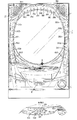
まず、遊技機の一例であるパチンコ遊技機の全体の構成について説明する。図1はパチンコ遊技機を正面からみた正面図である。図2は遊技枠11の前面を示す正面図である。図3は遊技盤の前面を示す正面図である。なお、以下の実施の形態では、パチンコ遊技機を例に説明を行うが、本発明による遊技機はパチンコ遊技機に限られず、スロット機などの他の遊技機に適用することもできる。また、図2には、遊技枠11の前面のうち打球供給皿(上皿)3部分を拡大した図も示されている。
Hereinafter, embodiments of the present invention will be described with reference to the drawings.
First, the overall configuration of a pachinko gaming machine that is an example of a gaming machine will be described. FIG. 1 is a front view of a pachinko gaming machine as viewed from the front. FIG. 2 is a front view showing the front of the
パチンコ遊技機1は、縦長の方形状に形成された外枠(図示せず)と、外枠の内側に開閉可能に取り付けられた遊技枠11とで構成される。また、パチンコ遊技機1は、遊技枠11に開閉可能に設けられている額縁状に形成されたガラス扉枠2を有する。遊技枠11は、外枠に対して開閉自在に設置される前面枠(図示せず)と、機構部品等が取り付けられる機構板と、それらに取り付けられる種々の部品(後述する遊技盤を除く。)とを含む構造体である。
The
図1〜図3に示すように、パチンコ遊技機1は、額縁状に形成されたガラス扉枠2を有する。ガラス扉枠2の下部表面には打球供給皿(上皿)3がある。打球供給皿3の下部には、打球供給皿3に収容しきれない遊技球を貯留する余剰球受皿4と遊技球を発射する打球操作ハンドル(操作ノブ)5が設けられている。ガラス扉枠2の背面には、図3に示すように、遊技枠11の一部を構成するプラ枠がある。プラ枠は、機構板を含み、機構板に電源回路(図示せず)やスピーカ27などの部品が取り付けられている。また、遊技枠11のプラ枠には、遊技枠11と遊技盤6との間の配線を中継する中継基板607が設けられている。また、遊技枠11の前面枠には、図3に示すように、遊技盤6が着脱可能に取り付けられている。なお、遊技盤6は、それを構成する板状体と、その板状体に取り付けられた種々の部品とを含む構造体である。また、遊技盤6の前面には遊技領域7が形成されている。
As shown in FIGS. 1 to 3, the
遊技領域7の中央付近には、それぞれが演出用の飾り図柄を可変表示する複数の可変表示部を含む可変表示装置(画像表示装置)9が設けられている。可変表示装置9には、例えば「左」、「中」、「右」の3つの可変表示部(図柄表示エリア)がある。可変表示装置9は、特別図柄表示器8による特別図柄の可変表示期間中に、装飾用(演出用)の図柄としての飾り図柄の可変表示を行う。飾り図柄の可変表示を行う可変表示装置9は、演出制御基板に搭載されている演出制御用マイクロコンピュータによって制御される。
Near the center of the
可変表示装置9の下方には、識別情報としての特別図柄を可変表示する特別図柄表示器(特別図柄表示装置)8が設けられている。この実施の形態では、特別図柄表示器8は、例えば00〜99の数字を可変表示可能な簡易で小型の表示器(例えば7セグメントLED)で実現されている。なお、特別図柄表示器8は、2桁の数字を表示するものに限らず、0〜9など他の桁数の数字を可変表示するように構成されていてもよい。また、可変表示装置9は、特別図柄表示器8による特別図柄の可変表示期間中に、装飾用(演出用)の図柄としての飾り図柄の可変表示を行う。
Below the
特別図柄表示器8の右側には、始動入賞口13,14に入った有効入賞球数すなわち保留記憶(始動記憶または始動入賞記憶ともいう。)数を表示する4つの表示器からなる特別図柄保留記憶表示器18が設けられている。有効始動入賞がある毎に、1つの表示器の表示色を変化させる。そして、特別図柄表示器8の可変表示が開始される毎に、1つの表示器の表示色をもとに戻す。なお、可変表示装置9の表示領域内に、保留記憶数を表示する4つの表示領域からなる特別図柄保留記憶表示領域を設けるようにしてもよい。また、この実施の形態では、保留記憶数の上限値を4とするが、上限値をより大きい値にしてもよい。さらに、上限値を、遊技状態に応じて変更可能であるようにしてもよい。
On the right side of the
可変表示装置9の下方には、第1始動入賞口13が設けられている。第1始動入賞口13に入賞した遊技球は、遊技盤6の背面に導かれ、第1始動口スイッチ13aによって検出される。また、可変表示装置9の左側には、第2始動入賞口14を形成する可変入賞装置15が設けられている。第2始動入賞口14に入った入賞球は、遊技盤6の背面に導かれ、始動口スイッチ14aによって検出される。可変入賞球装置15は、ソレノイド16によって開状態にされる。
A first
可変表示装置9の右側には、遊技演出に用いられる可動部材としてのトロッコ151が設けられている。トロッコ151は、遊技演出において、演出制御手段の制御に従って、図4に示すように、可変表示装置9の右側から左側方向に飛び出すような演出を行うことができる。
On the right side of the
また、可変表示装置9の上部および右側には、遊技演出に用いられる可動部材としての梁152が設けられている。梁152は、遊技演出において、演出制御手段の制御に従って、図5に示すように、可変表示装置9の上部および右側から崩れ落ちるような演出を行うことができる。
Further, on the upper and right sides of the
さらに、可変表示装置9の下部には、遊技演出に用いられる可動部材としての骸骨153が設けられている。骸骨153は、遊技演出において、演出制御手段の制御に従って、図6に示すように、口の部分が開閉するような演出を行うことができる。また、骸骨153は、特別可変入賞球装置20を備え、大入賞口を形成している。この実施の形態では、骸骨153は、特定遊技状態(大当り状態)においてソレノイド21によって特別可変入賞球装置20が開放状態に制御されることによって入賞領域となる大入賞口が開放状態になる。大入賞口に入賞した入賞球はカウントスイッチ23で検出される。
Furthermore, a
また、パチンコ遊技機1は、遊技の進行中に遊技者が操作可能な操作ボタン81a〜81eを備えている。例えば、操作ボタン81a〜81eが操作(押下)されると、可動部材としてのトロッコ151や梁152、骸骨153が動作する。
The
ゲート32に遊技球が入賞しゲートスイッチ32aで検出されると、普通図柄表示器10の表示の可変表示が開始される。この実施の形態では、左右のランプ(点灯時に図柄が視認可能になる)が交互に点灯することによって可変表示が行われ、例えば、可変表示の終了時に右側のランプが点灯すれば当りになる。そして、普通図柄表示器10における停止図柄が所定の図柄(当り図柄)である場合に、可変入賞球装置15が所定回数、所定時間だけ開放状態になる。普通図柄表示器10の下部には、ゲート32に入った入賞球数を表示する4つのLEDによる表示部を有する普通図柄始動記憶表示器41が設けられている。ゲート32への入賞がある毎に、普通図柄始動記憶表示器41は点灯するLEDを1増やす。そして、普通図柄表示器10の可変表示が開始される毎に、点灯するLEDを1減らす。
When a game ball wins the
遊技盤6には、複数の入賞口(普通入賞口)29,30,33,39が設けられ、遊技球の入賞口29,30,33,39への入賞は、それぞれ入賞口スイッチ29a,30a,33a,39aによって検出される。各入賞口29,30,33,39は、遊技媒体を受け入れて入賞を許容する領域として遊技盤6に設けられる入賞領域を構成している。なお、始動入賞口13,14や大入賞口も、遊技媒体を受け入れて入賞を許容する入賞領域を構成する。また、それぞれの入賞口29,30,33,39に入賞した遊技球を1つのスイッチで検出するようにしてもよい。
The
遊技領域7の中央部には、可変表示装置9を囲むように飾り部材154が取り付けられており、飾り部材154の上部には、遊技中に点灯表示したり点滅表示される装飾ランプ(センター飾り用ランプ)が設けられている。なお、この実施の形態では、センター飾り用ランプとして6個のLED125a〜125fが設けられている。また、飾り部材154には、可変表示装置9を囲むように、遊技中に点灯表示したり点滅表示される装飾ランプ(ステージランプ)が設けられている。なお、この実施の形態では、ステージランプとして6個のLED126a〜126fが設けられている。
A
また、遊技領域7の下部には、入賞しなかった遊技球を吸収するアウト口26がある。また、遊技領域7の外側の左右上部には、効果音を発する2つのスピーカ27が設けられている。遊技領域7の外周には、天枠ランプ、左枠ランプおよび右枠ランプが設けられている。さらに、遊技領域7における各構造物の周囲には装飾LEDが設置されている。天枠ランプ、左枠ランプ、右枠ランプおよび装飾用LEDは、遊技機に設けられている装飾発光体の一例である。この実施の形態では、天枠ランプとして12個のLED281a〜281lが設けられている。また、左枠ランプとして6個のLED282a〜282fが設けられている。また、右枠ランプとして6個のLED283a〜283fが設けられている。また、構造物の周囲の装飾LEDとして、骸骨153に1個のLED127aが、特別可変入賞球装置20に2個のLED127b,127cが、操作ボタン81a〜81eに1個のLED83が、打球供給皿3に4個のLED82a〜82dが設けられている。
Further, at the lower part of the
打球発射装置から発射された遊技球は、打球レールを通って遊技領域7に入り、その後、遊技領域7を下りてくる。遊技球が第1始動入賞口13に入り第1始動口スイッチ13aで検出されると、または遊技球が第2始動入賞口14に入り第2始動入賞口スイッチ14aで検出されると、図柄の可変表示を開始できる状態であれば、特別図柄表示器8において特別図柄が可変表示(変動)を始めるとともに、可変表示装置9において飾り図柄が可変表示(変動)を始める。図柄の可変表示を開始できる状態でなければ、始動入賞記憶数を1増やす。
The game balls launched from the hit ball launching device enter the
特別図柄表示器8における特別図柄の可変表示、および可変表示装置9における飾り図柄の可変表示は、一定時間が経過したときに停止する。停止時の特別図柄(停止図柄)が大当り図柄(特定表示結果)であると、大当り遊技状態に移行する。すなわち、大入賞口が、一定時間経過するまで、または、所定個数(例えば10個)の遊技球が入賞するまで開放する。
The variable display of the special symbol on the
遊技球がゲート32に入賞すると、普通図柄表示器10において普通図柄が可変表示される状態になる。また、普通図柄表示器10における停止図柄が所定の図柄(当り図柄)である場合に、可変入賞球装置15が所定時間だけ開放状態になる。さらに、確変状態では、普通図柄表示器10における停止図柄が当り図柄になる確率が高められるとともに、可変入賞球装置15の開放時間と開放回数が高められる。また、時短状態(特別図柄の可変表示時間が短縮される遊技状態)において、可変入賞球装置15の開放時間と開放回数が高められるようにしてもよい。
When the game ball wins the
上記のように、この実施の形態のパチンコ遊技機1には、発光体としてのランプやLEDが各所に設けられている。さらに、プリペイドカードが挿入されることによって球貸しを可能にするプリペイドカードユニット(以下、単に「カードユニット」ともいう。)が、パチンコ遊技機1に隣接して設置される(図示せず)。
As described above, the
図7は、遊技枠11を開いた状態を示す説明図である。図7に示すように、遊技枠11側の裏面には、ICなどを搭載するための4つの基板(枠側IC基板)602〜605が取り付けられている。遊技枠11の上部に取り付けられた枠側IC基板602は、シリアルデータをパラレルデータに変換するシリアル−パラレル変換IC611,612が搭載されており、各シリアル−パラレル変換IC611,612から、天枠ランプの各LED281a〜281lに制御信号が供給される。また、遊技枠11の右側(裏面から見て左側)に取り付けられた枠側IC基板603は、シリアル−パラレル変換IC613が搭載されており、シリアル−パラレル変換IC613から、右枠ランプの各LED283a〜283fに制御信号が供給される。また、遊技枠11の左側(裏面から見て右側)に取り付けられた枠側IC基板604は、シリアル−パラレル変換IC614が搭載されており、シリアル−パラレル変換IC614から、左枠ランプの各LED282a〜282fに制御信号が供給される。
FIG. 7 is an explanatory diagram showing a state in which the
また、遊技枠11の下部に取り付けられた枠側IC基板605は、シリアル−パラレル変換IC615、およびパラレルデータをシリアルデータに変換する入力IC620が搭載されており、シリアル−パラレル変換IC615から、操作ボタン81a〜81eに設けられた操作ボタンランプのLED83および打球供給皿(上皿)3に設けられた皿ランプの各LED82a〜82dに制御信号が供給される。また、操作ボタン81a〜81eからの検出信号が入力IC620にパラレルに入力される。なお、図7には、枠側IC基板605を横から見た図も示されている。
The frame
なお、図7に示すように、この実施の形態では、各枠側IC基板602〜605のうち遊技枠11の上部に取り付けられた枠側IC基板602は、2つのシリアル−パラレル変換ICを搭載した集合基板として構成されている。そのように構成することによって、シリアル−パラレル変換ICを搭載する基板を集約することができ、遊技機における部品点数を低減することができる。
As shown in FIG. 7, in this embodiment, the frame
また、図7に示すように、遊技枠11側には中継基板607が取り付けられており、中継基板607からの配線は、枠側IC基板604に接続され、枠側IC基板604から枠側IC基板602に接続され、さらに枠側IC基板602から枠側IC基板603に接続される。また、中継基板607からの配線は、枠側基板605に接続される。また、各枠側IC基板602〜604間の配線や、枠側IC基板604,605と中継基板607との間の配線は、図7に示すように、各基板にコネクタ156a〜156hを用いて接続される。なお、図7では、基板に垂直方向に接続するタイプのコネクタを用いて配線接続を行う場合を示しているが、例えば、基板に対して水平方向に接続するタイプのコネクタを用いて配線接続を行うようにしてもよい。
Also, as shown in FIG. 7, a
図7に示すように、中継基板607のコネクタ156aからの配線は、枠側IC基板604のコネクタ156bに接続される。枠側IC基板604の配線パターンは、コネクタ156bからさらに分岐され、一方がシリアル−パラレル変換IC614に接続され、他の一方がコネクタ156cに接続されるようになっている。また、枠側IC基板604において、コネクタ156cは、枠側IC基板602側の端部に配置されている。枠側IC基板604のコネクタ156cからの配線は、枠側IC基板602のコネクタ156dに接続される。枠側IC基板602の配線パターンは、コネクタ156dからさらに3つに分岐され、シリアル−パラレル変換IC611、シリアル−パラレル変換IC612およびコネクタ156eに接続されるようになっている。また、枠側IC基板602において、コネクタ156eは、枠側IC基板603側の端部に配置されている。枠側IC基板602のコネクタ156eからの配線は、枠側IC基板603のコネクタ156fに接続される。枠側IC基板603の配線パターンは、シリアル−パラレル変換IC613に接続されるようになっている。
As shown in FIG. 7, the wiring from the
また、中継基板607のコネクタ156gからの配線は、枠側IC基板605のコネクタ156hに接続される。枠側IC基板605の配線パターンは、コネクタ156hからさらに分岐され、一方がシリアル−パラレル変換IC615に接続され、他の一方が入力IC620に接続されるようになっている。
Further, the wiring from the connector 156g of the
また、図7に示すように、遊技枠11の開放を検出するためのドア開放センサ155が取り付けられている。
Further, as shown in FIG. 7, a
図8は、遊技盤6の裏面を示す説明図である。図8に示すように、遊技盤6の裏面には、ICなどを搭載するための基盤(盤側IC基板)601が取り付けられている。盤側IC基板601には、シリアルデータをパラレルデータに変換する4つのシリアル−パラレル変換IC616〜619が搭載されており、シリアル−パラレル変換IC616から、各可動部材151〜153を駆動するためのモータ151a,152a,153aに制御信号が供給される。また、シリアル−パラレル変換IC617から、センター飾り用ランプの各LED125a〜125fに制御信号が供給される。また、シリアル−パラレル変換IC618から、ステージランプの各LED126a〜126fに制御信号が供給される。また、シリアル−パラレル変換IC619から、可動部材である骸骨153および特別可変入賞球装置20に設けられた各ランプのLED127a〜127bに制御信号が供給される。
FIG. 8 is an explanatory view showing the back surface of the
なお、図8に示すように、この実施の形態では、盤側IC基板601は、4つのシリアル−パラレル変換ICを搭載した集合基板として構成されている。そのように構成することによって、シリアル−パラレル変換ICを搭載する基板を集約することができ、遊技機における部品点数を低減することができる。
As shown in FIG. 8, in this embodiment, the board
また、盤側IC基板601は、パラレルデータをシリアルデータに変換する入力IC621が搭載されており、各可動部材151〜153の位置を検出するための位置センサ151b,152b,153bからの検出信号が入力IC621にパラレルに入力される。
The board
また、図8に示すように、遊技盤6側には中継基板606が取り付けられており、遊技枠11側には中継基板607が設けられている。演出制御手段からの配線は、まず中継基板606に接続され、さらに中継基板607に接続される。そして、中継基板606からの配線は、盤側IC基板601に接続される。また、盤側IC基板601と中継基板606との間の配線や、中継基板606,607間の配線、中継基板606と演出制御手段との間の配線は、図8に示すように、各基板にコネクタ157a〜157eを用いて接続される。なお、コネクタ157a〜157eの接続方法は、図7に示すコネクタ156a〜156hの接続方法と同様である。
As shown in FIG. 8, a
また、各枠側IC基板602〜605に搭載されたシリアル−パラレル変換IC611〜615と、盤側IC基板601に搭載されたシリアル−パラレル変換IC616〜619とを中継する中継基板を設けるようにしてもよい。この場合、中継基板は、遊技枠11側と遊技盤6側とのいずれに配置されていてもよい。
Further, a relay board is provided to relay the serial-
また、演出制御基板80と各枠側IC基板602〜605に搭載されたシリアル−パラレル変換IC611〜615とを中継する中継基板を設けるようにしてもよい。この場合、中継基板は、遊技枠11側と遊技盤6側とのいずれに配置されていてもよい。
Further, a relay board may be provided to relay the
プラ枠の上皿には遊技球を払い出す穴の上側に開口が形成され、開口に中継基板607が設けられる。中継基板607は表裏のコネクタを介して中継する基板であり、プラ枠表側にコネクタ157bが配置され裏側にコネクタ156a,156gが配置されている。また、中継基板607は、遊技盤6が取り付けられる開口の端部に配置される。また、図7に示すように、中継基板607は、遊技盤6が取り付けられる開口の端部の形状に沿うような形状に形成されている。なお、中継基板607は、表側に配置されるコネクタ157bと裏側に配置されるコネクタ156a,156gとの位置が重ならないようにずれた状態とされている。
An opening is formed in the upper plate of the plastic frame above the hole for paying out the game ball, and a
遊技盤6の裏側には中継基板606が設けられる。中継基板606は、図8に示すように、遊技盤6の端部に、プラ枠の中継基板607の近傍に位置するように設けられる。中継基板606はコネクタを介して中継する基板であり、コネクタ157b〜157dが配置されている。また、コネクタ157bは、遊技盤6が搭載する演出制御用マイクロコンピュータ100に接続されている。
A
図9は、主基板(遊技制御基板)31における回路構成の一例を示すブロック図である。なお、図9には、払出制御基板37および演出制御基板80等も示されている。主基板31には、プログラムに従ってパチンコ遊技機1を制御する遊技制御用マイクロコンピュータ(遊技制御手段に相当)560が搭載されている。遊技制御用マイクロコンピュータ560は、ゲーム制御(遊技進行制御)用のプログラム等を記憶するROM54、ワークメモリとして使用される記憶手段としてのRAM55、プログラムに従って制御動作を行うCPU56、I/Oポート部57、およびパラレルデータをシリアルデータに変換して出力するシリアル出力回路を含む。この実施の形態では、ROM54およびRAM55は遊技制御用マイクロコンピュータ560に内蔵されている。すなわち、遊技制御用マイクロコンピュータ560は、1チップマイクロコンピュータである。1チップマイクロコンピュータには、少なくともCPU56のほかRAM55が内蔵されていればよく、ROM54は外付けであっても内蔵されていてもよい。また、I/Oポート部57は、外付けであってもよい。
FIG. 9 is a block diagram illustrating an example of a circuit configuration in the main board (game control board) 31. FIG. 9 also shows the
遊技制御用マイクロコンピュータ560には、さらに、ハードウェア乱数を発生する乱数回路が内蔵されている。 The game control microcomputer 560 further includes a random number circuit for generating hardware random numbers.
なお、遊技制御用マイクロコンピュータ560においてCPU56がROM54に格納されているプログラムに従って制御を実行するので、以下、遊技制御用マイクロコンピュータ560(またはCPU56)が実行する(または、処理を行う)ということは、具体的には、CPU56がプログラムに従って制御を実行することである。このことは、主基板31以外の他の基板に搭載されているマイクロコンピュータについても同様である。
In the game control microcomputer 560, the CPU 56 executes control in accordance with the program stored in the
また、ゲートスイッチ32a、第1始動口スイッチ13a、第2始動口スイッチ14a、カウントスイッチ23、入賞口スイッチ29a,30a,33a,39aからの検出信号を遊技制御用マイクロコンピュータ560に与える入力ドライバ回路58も主基板31に搭載されている。また、可変入賞球装置15を開閉するソレノイド16、および大入賞口を形成する特別可変入賞球装置20を開閉するソレノイド21を遊技制御用マイクロコンピュータ560からの指令に従って駆動する出力回路59も主基板31に搭載されている。
Also, an input driver circuit for supplying detection signals from the gate switch 32a, the first start port switch 13a, the second start port switch 14a, the count switch 23, and the winning
また、遊技制御用マイクロコンピュータ560は、特別図柄を可変表示する特別図柄表示器8、普通図柄を可変表示する普通図柄表示器10、特別図柄保留記憶表示器18および普通図柄保留記憶表示器41の表示制御を行う。
In addition, the game control microcomputer 560 includes a
また、遊技制御用マイクロコンピュータ560が搭載するシリアル出力回路78は、シフトレジスタなどによって構成され、CPU56が出力する演出制御コマンドをシリアルデータに変換して、中継基板77を介して演出制御基板80に送信する。また、シリアル出力回路78は、CPU56が出力する制御信号をシリアルデータに変換して、中継基板77を介して特別図柄表示器8や特別図柄保留記憶表示器18、普通図柄表示器10、普通図柄保留記憶表示器41に出力する。なお、特別図柄表示器8、特別図柄保留記憶表示器18、普通図柄表示器10および普通図柄保留記憶表示器41には、シリアルデータをパラレルデータに変換するシリアル−パラレル変換ICがそれぞれ設けられ、中継基板77からの制御信号をパラレルデータに変換して、特別図柄表示器8や特別図柄保留記憶表示器18、普通図柄表示器10、普通図柄保留記憶表示器41に供給される。
The
なお、大当り遊技状態の発生を示す大当り情報等の情報出力信号をホールコンピュータ等の外部装置に対して出力する情報出力回路(図示せず)も主基板31に搭載されている。
An information output circuit (not shown) that outputs an information output signal such as jackpot information indicating the occurrence of a jackpot gaming state to an external device such as a hall computer is also mounted on the
この実施の形態では、演出制御基板80に搭載されている演出制御手段(演出制御用マイクロコンピュータで構成される。)が、中継基板77を介して遊技制御用マイクロコンピュータ560からの演出制御コマンドをシリアルデータ方式として受信し、飾り図柄を可変表示する可変表示装置9の表示制御を行う。
In this embodiment, the effect control means (configured by the effect control microcomputer) mounted on the
また、演出制御基板80に搭載されている演出制御手段が、遊技盤6に設けられているセンター飾り用ランプ125a〜125fおよびステージランプ126a〜126fの表示制御を行うとともに、枠側に設けられている天枠ランプ281a〜281l、左枠ランプ282a〜282f、および右枠ランプ283a〜283fの表示制御を行い、スピーカ27からの音出力の制御を行う。
Further, the effect control means mounted on the
また、演出制御基板80の演出制御用マイクロコンピュータ100には、演出制御手段が出力する各ランプ125a〜125f,126a〜126f,281a〜281l,282a〜282f,283a〜283fを表示制御するための制御信号をパラレルデータからシリアルデータに変換するシリアル出力回路353が搭載されている。また、演出制御基板80の演出制御用マイクロコンピュータ100には、入力したシリアルデータをパラレルデータに変換して演出制御手段に出力するシリアル入力回路354が搭載されている。したがって、演出制御手段は、シリアル出力回路353を介して制御信号をシリアルデータ方式として出力することによって、各ランプ125a〜125f,126a〜126f,281a〜281l,282a〜282f,283a〜283fの表示制御を行う。
Further, the
また、遊技盤側には、シリアルデータをパラレルデータに変換するためのシリアル−パラレル変換ICが搭載された盤側IC基板601が設けられている。盤側IC基板601は、中継基板606を介して演出制御基板80と接続される。また、遊技枠11側には、シリアルデータをパラレルデータに変換するためのシリアル−パラレル変換ICが搭載された各枠側IC基板602,603,604,605が設けられている。各枠側IC基板602,603,604,605は、中継基板606,607を介して演出制御基板80と接続される。
On the game board side, a board-
なお、図9に示すように、演出制御基板80、中継基板606および中継基板607は、バス型に1系統の配線ルートで接続される。
As shown in FIG. 9, the
図10は、中継基板77および演出制御基板80の回路構成例を示すブロック図である。なお、図10に示す例では、演出制御に関して演出制御基板80のみを設ける場合を示すが、ランプドライバ基板および音声出力基板を設けてもよい。この場合、ランプドライバ基板および音声出力基板には、マイクロコンピュータは搭載されていないが、マイクロコンピュータを搭載してもよい。
FIG. 10 is a block diagram illustrating a circuit configuration example of the
演出制御基板80は、演出制御用CPU101、RAM(図示せず)、シリアル出力回路353、シリアル入力回路354、クロック信号出力部356および入力取込信号出力部357を含む演出制御用マイクロコンピュータ100を搭載している。なお、RAMは外付けであってもよい。演出制御基板80において、演出制御用CPU101は、内蔵または外付けのROM(図示せず)に格納されたプログラムに従って動作し、シリアル入力回路102および入力ポート103を介して演出制御コマンドを受信する。この場合、シリアル入力回路102は、シリアルデータ方式として受信した演出制御コマンドをパラレルデータに変換し出力する。また、演出制御用CPU101は、演出制御コマンドにもとづいて、VDP(ビデオディスプレイプロセッサ)109に可変表示装置9の表示制御を行わせる。
The
この実施の形態では、演出制御用マイクロコンピュータ100と共動して可変表示装置9の表示制御を行うVDP109が演出制御基板80に搭載されている。VDP109は、演出制御用マイクロコンピュータ100とは独立したアドレス空間を有し、そこにVRAMをマッピングする。VRAMは、画像データを展開するためのバッファメモリである。そして、VDP109は、VRAM内の画像データをフレームメモリを介して可変表示装置9に出力する。
In this embodiment, a
演出制御用CPU101は、受信した演出制御コマンドに従ってCGROM(図示せず)から必要なデータを読み出すための指令をVDP109に出力する。CGROMは、可変表示装置9に表示されるキャラクタ画像データや動画像データ、具体的には、人物、文字、図形や記号等(飾り図柄を含む)、および背景画像のデータをあらかじめ格納しておくためのROMである。VDP109は、演出制御用CPU101の指令に応じて、CGROMから画像データを読み出す。そして、VDP109は、読み出した画像データにもとづいて表示制御を実行する。
The
中継基板77には、主基板31から入力された信号を演出制御基板80に向かう方向にしか通過させない(演出制御基板80から中継基板77への方向には信号を通過させない)信号方向規制手段としての単方向性回路74が搭載されている。単方向性回路として、例えばダイオードやトランジスタが使用される。図10には、ダイオードが例示されている。
As a signal direction regulating means, the signal inputted from the
さらに、演出制御用CPU101は、シリアル出力回路353を介してランプを駆動する信号を出力する。シリアル出力回路は、入力したランプのLEDを駆動する信号(パラレルデータ)をシリアルデータに変換して中継基板606に出力する。また、演出制御用CPU101は、音声合成用IC173に対して音番号データを出力する。
Further, the
また、クロック信号出力部356は、クロック信号を中継基板606に出力する。クロック信号出力部356からのクロック信号は、中継基板606,607を介して各枠側IC基板602〜605に搭載されたシリアル−パラレル変換IC611〜615や入力IC620に供給される。また、クロック信号出力部356からのクロック信号は、中継基板606を介して盤側IC基板601に搭載されたシリアル−パラレル変換IC616〜619や入力IC621に供給される。したがって、この実施の形態では、各シリアル−パラレル変換IC611〜619および各入力IC620,621に共通のクロック信号が供給されることになる。
Further, the clock
また、入力取込信号出力部357は、演出制御用CPU101の指示に従って、中継基板606,607を介して、盤側IC基板601または枠側IC基板602〜605に入力取込信号(ラッチ信号)を出力する。枠側IC基板605に搭載された入力IC620は、演出制御用マイクロコンピュータ100からの入力取込信号を入力すると、操作ボタン81a〜81eの検出信号をラッチし、シリアルデータ方式として中継基板606,607を介して演出制御用マイクロコンピュータ100に出力する。また、盤側IC基板601に搭載された入力IC621は、演出制御用マイクロコンピュータ100からの入力取込信号を入力すると、各位置センサ151b,152b,153bの検出信号をラッチし、シリアルデータ方式として中継基板606を介して演出制御用マイクロコンピュータ100に出力する。
Further, the input capture
音声合成用IC173は、音番号データを入力すると、音番号データに応じた音声や効果音を発生し増幅回路175に出力する。増幅回路175は、音声合成用IC173の出力レベルを、ボリューム176で設定されている音量に応じたレベルに増幅した音声信号をスピーカ27に出力する。音声データROM174には、音番号データに応じた制御データが格納されている。音番号データに応じた制御データは、所定期間(例えば飾り図柄の変動期間)における効果音または音声の出力態様を時系列的に示すデータの集まりである。
When the
図11は、演出制御基板80、中継基板606,607、盤側IC基板601、枠側IC基板602,603,604,605の構成例を示すブロック図である。演出制御基板80の演出制御用マイクロコンピュータ100は、制御信号としてのシリアルデータとともに、クロック信号を中継基板607に出力する。また、入力IC620,621に入力信号をラッチさせるための入力取込信号を中継基板606に出力する。
FIG. 11 is a block diagram illustrating a configuration example of the
中継基板606は、演出制御用マイクロコンピュータ100から入力したシリアルデータおよびクロック信号を、盤側IC基板601に搭載された各シリアル−パラレル変換IC616〜619に供給する。そして、各シリアル−パラレル変換IC616〜619は、入力したシリアルデータをパラレルデータに変換して、遊技盤6に設けられた各ランプのLED125a〜125f,126a〜126f,127a〜127cや、各可動部材のモータ151a〜151cに供給する。
The
また、中継基板607は、バス型に1系統の配線ルートで中継基板606と接続されており、各シリアル−パラレル変換IC616〜619に接続されるシリアルデータ線300およびクロック信号線301は、盤側IC基板601上でバス形式に接続されている。なお、バス型に接続とは、1つの配線ルートに複数のシリアル−パラレル変換ICまたは中継基板が接続されていることである。
Further, the
また、盤側IC基板601に搭載された各シリアル−パラレル変換IC616〜619にはそれぞれ固有のIDがある。この実施の形態では、図11に示すように、IC616のIDは06であり、IC617のIDは07であり、IC618のIDは08であり、IC619のIDは09である。
Each serial-
また、盤側IC基板601には、遊技盤6上に設けられた各可動部材の位置センサの検出信号を入力する入力IC621が搭載されている。この実施の形態では、盤側IC基板601に搭載された入力IC621と演出制御用マイクロコンピュータ100とは、中継基板606を介して入力信号線302、クロック信号線301および入力取込信号線303が接続されており、演出制御用マイクロコンピュータ100は、所定のタイミングで、入力取込信号を中継基板606を介して入力IC621に出力する。すると、入力IC621は、入力取込信号(ラッチ信号)にもとづいて各位置センサの検出信号をラッチし、中継基板606を介して演出制御用マイクロコンピュータ100に出力する。この場合、入力IC621は、各位置センサからパラレルに入力した検出信号をシリアルデータに変換して出力する。なお、この実施の形態では、図11に示すように、入力IC621の固有のIDは11である。
In addition, an
中継基板607に入力されたシリアルデータおよびクロック信号は、図11に示すように、各枠側IC基板602〜605に搭載された各シリアル−パラレル変換IC611〜615に供給される。そして、各シリアル−パラレル変換IC611〜615は、入力したシリアルデータをパラレルデータに変換して、遊技枠11に設けられた各ランプのLED281a〜281l,282a〜282f,283a〜283f,82a〜82d,83に供給する。
As shown in FIG. 11, the serial data and the clock signal input to the
また、各シリアル−パラレル変換IC611〜614に接続されるシリアルデータ線およびクロック信号線は、各枠側IC基板602〜604上でバス形式に接続されている。この実施の形態では、図11に示すように、まず、枠側IC基板604のシリアル−パラレル変換IC614に入力され、シリアル−パラレル変換IC614から枠側IC基板602のシリアル−パラレル変換IC611およびシリアル−パラレル変換IC612の順に入力され、さらにシリアル−パラレル変換IC612から枠側IC基板603のシリアル−パラレル変換IC613に入力される。また、シリアル−パラレル変換IC615に接続されるシリアルデータ線およびクロック信号線は、中継基板607から直接接続される。
The serial data lines and clock signal lines connected to the serial-
また、各枠側IC基板602〜605に搭載された各シリアル−パラレル変換IC611〜615にはそれぞれ固有のIDがある。この実施の形態では、図11に示すように、IC611のIDは01であり、IC612のIDは02であり、IC613のIDは03であり、IC614のIDは04であり、IC615のIDは05である。
Each serial-
また、枠側IC基板605には、遊技枠11に設けられた操作ボタン81a〜81eの検出信号を入力する入力IC620が搭載されている。この実施の形態では、枠側IC基板605に搭載された入力IC620と演出制御用マイクロコンピュータ100とは、中継基板606,607を介して入力信号線、クロック信号線および入力取込信号線が接続されており、演出制御用マイクロコンピュータ100は、所定のタイミングで、入力取込信号を中継基板606,607を介して入力IC620に出力する。この場合、演出制御用マイクロコンピュータ100は、入力IC621に入力取込信号を出力するタイミングとは異なるタイミングで、入力取込信号を入力IC620に出力する。すると、入力IC620は、入力取込信号(ラッチ信号)にもとづいて操作ボタン81a〜81eからの検出信号をラッチし、中継基板606,607を介して演出制御用マイクロコンピュータ100に出力する。この場合、入力IC620は、操作ボタン81a〜81eからパラレルに入力した検出信号をシリアルデータに変換して出力する。なお、この実施の形態では、図11に示すように、入力IC620の固有のIDは10である。
In addition, an
盤側IC基板601に搭載されたシリアル−パラレル変換IC616〜619と各枠側IC基板602〜605に搭載されたシリアル−パラレル変換IC611〜615とは、1系統の配線を介して接続されている。1系統の配線を介して接続とは、具体的には、各中継基板606,607がバス型に接続されているとともに、各シリアル−パラレル変換IC611〜619がバス型またはデイジーチェーン型に接続されていることである。なお、この実施の形態では、図11に示すように、各シリアル−パラレル変換IC611〜619はバス型に接続されている。このように、この実施の形態では、盤側IC基板601に搭載された各シリアル−パラレル変換IC616〜619と、各枠側IC基板602〜605に搭載された各シリアル−パラレルIC611〜615とが、中継基板606,607を介してコネクタ156a〜156h,157a〜157eを用いて1系統の配線を介して接続されている。そのため、コネクタの着脱を行うだけで遊技枠11と遊技盤6との配線作業を行うことができ、遊技枠11遊技盤6との着脱作業をさらに容易に行えるようにすることができる。
The serial-
また、この実施の形態によれば、盤側IC基板601に搭載されたシリアル−パラレル変換IC616〜619、枠側IC基板602〜605に搭載されたシリアル−パラレル変換IC611〜615および入力IC620,621に、演出制御用マイクロコンピュータ100から共通のクロック信号を入力する。そのため、シリアル−パラレル変換IC611〜619へのクロック信号の配線と入力IC620,621へのクロック信号の配線とを共通化することができ、演出制御手段と盤側IC601基板との間の通信、および演出制御手段と枠側IC基板602〜605との間の通信を、それぞれ1チャネルを用いて実現することができ、配線数を低減することができる。また、盤側IC基板601に搭載されたシリアル−パラレル変換IC616〜619、枠側IC基板602〜605に搭載されたシリアル−パラレル変換IC611〜615、および入力IC620,621とを容易に同期させることができ、クロック信号用の配線数も低減することができる。
In addition, according to this embodiment, the serial-
この実施の形態では、各シリアル−パラレル変換IC611〜619には、あらかじめアドレスが付与されており、演出制御用マイクロコンピュータ100は、シリアルデータに変換した制御信号を出力する際に、シリアルデータにアドレスを付加して出力する。各シリアル−パラレル変換IC611〜619は、シリアルデータを入力すると、入力したシリアルデータに付加されているアドレスが自分のアドレスに合致するか否かを確認し、合致していればパラレルデータに変換して各ランプのLEDに供給する(すなわち、出力する)。アドレスが合致していなければ各ランプのLEDへの供給は行わない。
In this embodiment, each serial-
なお、図11に示すように、演出制御用マイクロコンピュータ100は、盤側IC基板601および枠側IC基板602〜605と双方向通信を行う(具体的には、シリアルデータを各シリアル−パラレル変換IC611〜619に送信し、入力信号を入力IC620,621から入力する)ものであるので、データ入力端子とデータ出力端子とを備えており、1チャネルでデータ入力とデータ出力とを行うことができる。この実施の形態では、図11に示すように、1つのチャネルのデータ入力端子とデータ出力端子とを、それぞれ異なる出力対象機器(本例では、シリアル−パラレル変換IC611〜619)と入力対象機器(本例では、入力IC620,621)に接続している。そのように構成することによって、本来、出力対象機器と入力対象機器とが別の機器である場合にはそれぞれ別のチャネルを用いて通信を行うべきところを、1つのチャネルのみを用いて双方向通信を可能としており、演出制御用マイクロコンピュータ100と盤側IC基板601および枠側IC基板602〜605との間のチャネル数を低減している。
As shown in FIG. 11, the
この実施の形態において、チャネルとは、データ線(出力データ線)、クロック信号線、入力信号線(入力データ線)、および入力取込信号線(入力データの読出要求の信号線)用の端子をセットにしたものである。なお、1つのチャネルにアース線や電源専用の端子を含んでもよい。また、この実施の形態では、1チャネルを用いてデータ入力とデータ出力の両方を行う場合を示すが、データ線(出力データ線)およびクロック信号線用の端子のみをセットにした出力専用のチャネルを用いてもよい。また、入力信号線(入力データ線)および入力取込信号線(入力データの読出要求の信号線)用の端子のみをセットにした入力専用のチャネルを用いてもよい。 In this embodiment, the channel is a terminal for a data line (output data line), a clock signal line, an input signal line (input data line), and an input take-in signal line (signal line for input data read request). Is a set. One channel may include a ground wire or a terminal dedicated to the power source. Further, in this embodiment, a case where both data input and data output are performed using one channel is shown, but an output-dedicated channel in which only a terminal for a data line (output data line) and a clock signal line is set. May be used. Alternatively, an input-only channel in which only terminals for input signal lines (input data lines) and input take-in signal lines (input data read request signal lines) are set may be used.
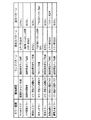
図12および図13は、各シリアル−パラレル変換IC611〜619に付与されるアドレスの例を示す説明図である。この実施の形態では、演出制御用マイクロコンピュータ100は、あらかじめRAMに設けられた所定のアドレス記憶領域に、図12および図13に示す各シリアル−パラレル変換IC611〜619のアドレスを記憶している。
12 and 13 are explanatory diagrams showing examples of addresses given to the serial-
この実施の形態では、図12および図13に示すように、各枠側IC基板602〜605に搭載されたシリアル−パラレル変換IC611〜615において、IC611にはアドレス01が付与され、IC612にはアドレス02が付与され、IC613にはアドレス03が付与され、IC614にはアドレス04が付与され、IC615にはアドレス05が付与されている。また、盤側IC基板601に搭載されたシリアル−パラレル変換IC616〜619において、IC616にはアドレス06が付与され、IC617にはアドレス07が付与され、IC618にはアドレス08が付与され、IC619にはアドレス09が付与されている。
In this embodiment, as shown in FIGS. 12 and 13, in the serial-
なお、各シリアル−パラレル変換IC611〜619に、アドレスとしてICの固有のIDと同じものを付与してもよく、ICの固有のIDとは異なる数字や文字、記号を含むアドレスを付与してもよい。
The serial-
また、図12および図13に示すように、アドレスが01であるシリアル−パラレル変換IC611は、シリアルデータをパラレルデータに変換し、遊技枠11の天枠ランプのLED(本例では天枠ランプ281a〜281lのうちのLED6個(281a〜281f))に供給する。また、アドレスが02であるシリアル−パラレル変換IC612は、シリアルデータをパラレルデータに変換し、遊技枠11の天枠ランプのLED(本例では天枠ランプ281a〜281lの他のLED6個(281g〜281l))に供給する。また、アドレスが03であるシリアル−パラレル変換IC613は、シリアルデータをパラレルデータに変換し、遊技枠11の右枠ランプのLED(本例ではLED6個(283a〜283f))に供給する。また、アドレスが04であるシリアル−パラレル変換IC614は、シリアルデータをパラレルデータに変換し、遊技枠11の左枠ランプのLED(本例ではLED6個(282a〜282f))に供給する。
As shown in FIGS. 12 and 13, the serial-
また、アドレスが05であるシリアル−パラレル変換IC615は、シリアルデータをパラレルデータに変換し、遊技枠11の打球供給皿3に設けられた皿ランプ(本例ではLED4個(82a〜82d))に供給するとともに、操作ボタン81a〜81eに設けられた操作ボタンランプ83(本例ではランプ1個)に供給する。
Further, the serial-
また、アドレスが06であるシリアル−パラレル変換IC616は、シリアルデータをパラレルデータに変換し、遊技盤6に設けられた各可動部材(本例では、梁、トロッコおよび骸骨の形状を模した役物)を駆動するためのモータ(本例ではモータ3個(151a,152a,153a)のそれぞれ正方向と逆方向)に供給する。また、アドレスが07であるシリアル−パラレル変換IC617は、シリアルデータをパラレルデータに変換し、遊技盤6中央に設けられた装飾用構造物(センター飾り)の各ランプ(本例ではLED6個(125a〜125f))に供給する。また、アドレスが08であるシリアル−パラレル変換IC618は、シリアルデータをパラレルデータに変換し、可変表示装置9の周囲に設けられた各ステージランプ(本例ではLED6個(126a〜126f))に供給する。また、アドレスが09であるシリアル−パラレル変換IC619は、シリアルデータをパラレルデータに変換し、可動部材(本例では骸骨153)周辺に設けられたランプのLED(本例ではLED3個(127a〜127c))に供給する。
Further, the serial-
また、この実施の形態では、各入力IC620,621にも、あらかじめアドレスが付与されている。図14は、各入力IC620,621に付与されるアドレスの例を示す説明図である。そして、演出制御用マイクロコンピュータ100は、あらかじめRAMに設けられた所定のアドレス記憶領域に、各入力IC620,621のアドレスを記憶している。この実施の形態では、図14に示すように、枠側IC基板605に搭載された入力IC620にはアドレス10が付与され、盤側IC基板601に搭載された入力IC621にはアドレス11が付与されている。
In this embodiment, each
なお、各入力IC620,621に、アドレスとしてICの固有のIDと同じものを付与してもよく、ICの固有のIDとは異なる数字や文字、記号を含むアドレスを付与してもよい。
Each
また、図14に示すように、アドレスが10である入力IC620は、遊技枠11に設けられた操作ボタン81a〜81eの検出信号(操作ボタン81a〜81e自体がオンされたか否か、操作ボタン81a〜81eの上下左右のいずれの部位がオンされたかを示す信号)をパラレルで入力し、シリアルデータに変換して出力する。また、アドレスが11である入力IC621は、遊技盤6の各可動部材に設けられた位置センサ151b,152b,153b(本例では3個)の検出信号をパラレルで入力し、シリアルデータに変換して出力する。
Further, as shown in FIG. 14, the
図15は、各シリアル−パラレル変換IC611〜619の構成を示すブロック図である。図15に示すように、シリアル−パラレル変換IC611〜619は、データラッチ部651、シフトレジスタ652、ヘッダ/アドレス検出部653、データバッファ655およびシンクドライバ656を含む。
FIG. 15 is a block diagram showing the configuration of each serial-parallel conversion IC 611-619. As illustrated in FIG. 15, the serial-
データラッチ部651は、例えばラッチ回路によって構成され、シリアルデータが入力されると、クロック信号のパルスの立ち上がりのタイミングで入力データを1ビット毎にラッチし、シフトレジスタ652に出力する。シフトレジスタ652は、データラッチ部651から1ビットずつ入力されたデータを順に格納する。また、シフトレジスタ652は、クロック信号のパルスの立ち上がりのタイミングで、格納データを1ビットずつシフトする。そのように繰り返し格納データを1ビットずつシフトしていくことによって、最終的にシフトレジスタ652にシリアルデータとして(すなわち、シリアル方式で)入力したデータが格納されることになる。
The data latch
図16は、演出制御用マイクロコンピュータ100から出力されるシリアルデータのフォーマットの例を示す説明図である。図16(A)は、遊技盤6や遊技枠11に設けられた各ランプのLEDを個別に点灯または消灯させるためのランプ点灯データとして出力されるシリアルデータのデータフォーマットである。また、図16(B)は、遊技盤6や遊技枠11に設けられた各ランプのLEDをリセットして全て消灯させるためのリセットコマンドとして出力されるシリアルデータのフォーマットである。
FIG. 16 is an explanatory diagram showing an example of the format of serial data output from the
図16(A)に示すように、ランプ点灯データは、28ビットで構成され、9ビットのヘッダデータ、マークビット(M)、8ビットのアドレス、8ビットのデータおよびエンドビット(E)を含む。 As shown in FIG. 16A, the lamp lighting data is composed of 28 bits, and includes 9-bit header data, mark bits (M), 8-bit addresses, 8-bit data, and end bits (E). .
ヘッダデータは、データの先頭を表すものであり、本例では1FF(h)である。マークビット(M)は、データの区切りを表すビット(本例では論理値0)であり、ヘッダデータとアドレスとの間、およびアドレスとデータとの間にそれぞれ挿入される。アドレスは、データ出力先のシリアル−パラレル変換ICのアドレスである。なお、アドレスとして、各シリアル−パラレル変換IC611〜619の固有の通し番号であるIDを用いてもよい。
The header data represents the head of the data, and is 1FF (h) in this example. The mark bit (M) is a bit (
データ(8ビット)は、各ランプのLEDの点灯状態を制御するためのものであり、例えば、点灯対象のランプのLEDに対応するビットとして論理値1を含み、非点灯対象のランプのLEDに対応するビットとして論理値0を含む。エンドビット(E)は、データの終了を示すものであり、本例では論理値0である。
The data (8 bits) is for controlling the lighting state of the LED of each lamp, and includes, for example, a
図16(B)に示すように、リセットコマンドは、19ビットで構成され、9ビットのヘッダデータ、マークビット(M)、8ビットのリセットデータおよびエンドビット(E)を含む。 As shown in FIG. 16B, the reset command is composed of 19 bits and includes 9-bit header data, mark bits (M), 8-bit reset data, and end bits (E).
ヘッダデータは、データの先頭を表すものであり、本例では1FF(h)である。マークビット(M)は、データの区切りを表すビット(本例では論理値0)であり、ヘッダデータとリセットデータとの間に挿入される。リセットデータは、各ランプのLEDの点灯状態をリセットして全て消灯させるためのものであり、例えば、全て論路値1を含むデータである。エンドビット(E)は、データの終了を示すものであり、本例では論理値0である。
The header data represents the head of the data, and is 1FF (h) in this example. The mark bit (M) is a bit (
この実施の形態では、図16(A)に示すランプ点灯データまたは図16(B)に示すリセットコマンドが入力され、クロック信号のパルスの立ち上がりのタイミングで、ビット単位で繰り返しシフトされてシフトレジスタ652に格納されることになる。
In this embodiment, the lamp lighting data shown in FIG. 16A or the reset command shown in FIG. 16B is input, and the
ヘッダ/アドレス検出部653は、シフトレジスタ652の格納データからヘッダおよびアドレスを検出する。まず、ヘッダ/アドレス検出部653は、シフトレジスタ652からのデータを常時検出し、検出したデータの内容がヘッダデータに相当する1FF(h)と一致するか否かを確認する。ヘッダデータ(1FF(h))と一致すれば、そのヘッダデータと一致した箇所をデータの先頭と判断し、シフトレジスタ652に1セットのランプ点灯データまたはリセットコマンドが格納されたと判断する。次いで、ヘッダ/アドレス検出部653は、シフトレジスタ652からアドレスに相当する先頭から11ビット目〜18ビット目のデータを検出し、そのシリアル−パラレル変換ICにあらかじめ付与されたアドレスと一致するか否かを確認する。盤側IC基板601および各枠側IC基板602〜605には、例えば、それぞれ搭載するシリアル−パラレル変換ICのアドレスを格納したアドレス格納レジスタ654が設けられており、ヘッダ/アドレス検出部653は、シフトレジスタ652から検出したアドレスが、あらかじめアドレス格納レジスタ654に格納するアドレスと一致するか否かを確認すればよい。アドレスが一致すれば、ヘッダ/アドレス検出653は、そのシリアル−パラレル変換ICを宛先とするデータを入力したと判定し、入力取込信号(ラッチ信号)をデータバッファ655に出力する。アドレスが一致しなければ、ヘッダ/アドレス検出653は、入力取込信号をデータバッファ655に出力しない。すなわち、この場合、そのシリアル−パラレル変換ICを宛先とするデータではないので、シフトレジスタ652に格納したデータをデータバッファ655に出力することなく、そのまま破棄することになる。
The header /
なお、図15では、盤側IC基板601および各枠側IC基板602〜605にあらかじめアドレス格納レジスタ654が設けられている場合を示しているが、アドレス格納レジスタ654に代えて、シリアル−パラレル変換ICに設けられているアドレス端子(8端子(8ビットのアドレスの各ビットにそれぞれ対応する))を介して、外部のハードウェア回路(例えば、演出制御基板80が搭載する回路)からアドレスを入力するようにしてもよい。そして、外部のハードウェア回路側から、各アドレス端子の入力をhighまたはlowに制御することによって、シリアル−パラレル変換ICにアドレスを入力してもよい。この場合、例えば、外部のハードウェア回路は、アドレスのいずれかのビットに対応する端子に電圧をかけることによってその端子に対する入力をhighとし、またはグランドにスイッチングすることによってその端子に対する入力をLowとするように制御する。
15 shows a case where the
データバッファ655は、例えば、ラッチレジスタによって構成され、ヘッダ/アドレス検出部653から入力取込信号を入力すると、シフトレジスタ652からデータ部分に相当する先頭から20ビット目〜27ビット目のデータを取り込んでラッチする。そして、データバッファ655は、取り込んだデータをパラレルデータ(Q0〜Q7)として各ランプのLEDに供給(すなわち、出力)することになる。
The
なお、シフトレジスタ652が格納したデータがリセットコマンドであった場合には、先頭から11ビット目〜18ビット目が全て論理値1のデータを格納することになる。この場合、データバッファ655は全ての論理値が1であるデータを取り込んだ場合にはリセットコマンドを入力したと判断し、全てのランプのLEDがリセットされ消灯されることになる。
If the data stored in the
シンクドライバ656は、所定の論理反転設定信号にもとづいて、データバッファ655が出力するパラレルデータの論理値を反転して出力したり、そのまま出力したりする。例えば、所定の論理反転設定信号がHighである場合には、データバッファ655が出力するパラレルデータのビット値が1である(すなわち、ランプ点灯データの対応するビット値が1)ときにオンとなり、各ランプのLEDにオン信号を出力する。この実施の形態では、あらかじめ論理反転設定信号の設定値が盤側IC基板601や各枠側IC基板602〜605に設けられたレジスタなどに設定されており、あらかじめ設定された設定値に従って各ランプのLEDにオン信号が出力され、各ランプのLEDが点灯するものとする。
The sync driver 656 inverts and outputs the logical value of the parallel data output from the
図17は、シリアル−パラレル変換ICへのシリアルデータおよびクロック信号の入力タイミングと、パラレルデータの出力タイミングとの例を示すタイミング図である。なお、図17では、シリアルデータ方式としてランプ点灯データを入力する場合を説明する。図17に示すように、シリアルデータは、ヘッダデータ、マークビット、アドレス、マークビット、データ、エンドビットの順に、シリアル−パラレル変換ICのシフトレジスタ652に1ビット単位で入力される。そして、この一連のデータを1セットとする。1セットのシリアルデータ(本例ではランプ点灯データ)が全て入力され終わるまで、ヘッダ/アドレス検出部653ではヘッダデータが検出されないので、データバッファ655の出力は変化しない。そのため、シリアル−パラレル変換ICからは、前回受信したシリアルデータにもとづく点灯パターンがそのままパラレルデータ方式として出力されている。
FIG. 17 is a timing diagram showing an example of the input timing of serial data and clock signals to the serial-parallel conversion IC and the output timing of parallel data. In FIG. 17, a case where lamp lighting data is input as a serial data method will be described. As shown in FIG. 17, the serial data is input to the
1セットのシリアルデータが全て入力され終わると、シフトレジスタ652の格納データからデータ部分がデータバッファ655にラッチされ、新たに受信したシリアルデータにもとづく点灯パターンがパラレルデータ方式として出力される。なお、この実施の形態では、図17に示すように、シリアル−パラレル変換ICが出力するパラレルデータのうち、Q0,Q4は、シリアルデータ入力完了後の次のクロック信号のパルスの立ち上がりのタイミングで、直ちに新たな点灯パターンのデータに切り替わる。また、Q1,Q5は、Q0,Q4より1クロック分遅れて新たな点灯パターンのデータに切り替わる。また、Q2,Q6は、Q0,Q4より2クロック分遅れて新たな点灯パターンのデータに切り替わる。さらに、Q3,Q7は、Q0,Q4より3クロック分遅れて新たな点灯パターンのデータに切り替わる。
When all sets of serial data have been input, the data portion from the data stored in the
図18は、各入力IC620,621の構成を示すブロック図である。図18に示すように、この実施の形態では、各入力IC620,621は、複数(本例では8個)のDフリップフロップ661〜668によって構成される。この実施の形態では、操作ボタン81a〜81eまたは各位置センサ151b,152b,153bからの検出信号が各入力IC620,621にパラレルに入力され、検出信号ごとにいずれかのDフリップフロップ661〜668に入力される。また、各Dフリップフロップ661〜668にはクロック信号が入力され、各Dフリップフロップ661〜668は、クロックの立ち上がりで順次シフト動作を行う。そして、パラレルに入力した検出信号をシリアルデータに変換して出力することになる。
FIG. 18 is a block diagram illustrating the configuration of each of the
各Dフリップフロップ661〜668には、演出制御用マイクロコンピュータ100から所定のタイミングで入力取込信号(ラッチ信号)が入力される。入力取込信号が入力されると、操作ボタン81a〜81eまたは各位置センサ151b,152b,153bから検出信号が、各Dフリップフロップ661〜668にラッチされる。そして、ラッチされた検出信号は、クロックの立ち上がりで順次シフトされ、シリアルデータ方式として出力される。
An input capture signal (latch signal) is input to each of the D flip-flops 661 to 668 from the
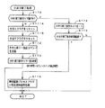
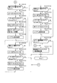
次に、遊技機の動作について説明する。図19は、主基板31における遊技制御用マイクロコンピュータ560が実行するメイン処理を示すフローチャートである。遊技機に対して電源が投入され電力供給が開始されると、リセット信号が入力されるリセット端子の入力レベルがハイレベルになり、遊技制御用マイクロコンピュータ560(具体的には、CPU56)は、プログラムの内容が正当か否か確認するための処理であるセキュリティチェック処理を実行した後、ステップS1以降のメイン処理を開始する。メイン処理において、CPU56は、まず、必要な初期設定を行う。
Next, the operation of the gaming machine will be described. FIG. 19 is a flowchart showing main processing executed by the game control microcomputer 560 on the
初期設定処理において、CPU56は、まず、割込禁止に設定する(ステップS1)。次に、割込モードを割込モード2に設定し(ステップS2)、スタックポインタにスタックポインタ指定アドレスを設定する(ステップS3)。そして、内蔵デバイスの初期化(内蔵デバイス(内蔵周辺回路)であるCTC(カウンタ/タイマ)およびPIO(パラレル入出力ポート)の初期化など)を行った後(ステップS4)、RAMをアクセス可能状態に設定する(ステップS5)。なお、割込モード2は、CPU56が内蔵する特定レジスタ(Iレジスタ)の値(1バイト)と内蔵デバイスが出力する割込ベクタ(1バイト:最下位ビット0)とから合成されるアドレスが、割込番地を示すモードである。
In the initial setting process, the CPU 56 first sets the interrupt prohibition (step S1). Next, the interrupt mode is set to interrupt mode 2 (step S2), and a stack pointer designation address is set to the stack pointer (step S3). After initialization of the built-in device (CTC (counter / timer) and PIO (parallel input / output port), which are built-in devices (built-in peripheral circuits)) is performed (step S4), the RAM is accessible (Step S5). In the interrupt
次いで、CPU56は、入力ポートを介して入力されるクリアスイッチ(例えば、電源基板に搭載されている。)の出力信号の状態を確認する(ステップS6)。その確認においてオンを検出した場合には、CPU56は、通常の初期化処理を実行する(ステップS10〜S15。S44,S45を含む。)。 Next, the CPU 56 checks the state of the output signal of the clear switch (for example, mounted on the power supply board) input via the input port (step S6). When the ON is detected in the confirmation, the CPU 56 executes a normal initialization process (steps S10 to S15, including S44 and S45).
クリアスイッチがオンの状態でない場合には、遊技機への電力供給が停止したときにバックアップRAM領域のデータ保護処理(例えばパリティデータの付加等の電力供給停止時処理)が行われたか否か確認する(ステップS7)。そのような保護処理が行われていないことを確認したら、CPU56は初期化処理を実行する。バックアップRAM領域にバックアップデータがあるか否かは、例えば、電力供給停止時処理においてバックアップRAM領域に設定されるバックアップフラグの状態によって確認される。 If the clear switch is not on, check whether data protection processing of the backup RAM area (for example, power supply stop processing such as addition of parity data) was performed when power supply to the gaming machine was stopped (Step S7). When it is confirmed that such protection processing is not performed, the CPU 56 executes initialization processing. Whether there is backup data in the backup RAM area is confirmed, for example, by the state of the backup flag set in the backup RAM area in the power supply stop process.
電力供給停止時処理が行われたことを確認したら、CPU56は、バックアップRAM領域のデータチェックを行う(ステップS8)。この実施の形態では、データチェックとしてパリティチェックを行う。よって、ステップS8では、算出したチェックサムと、電力供給停止時処理で同一の処理によって算出され保存されているチェックサムとを比較する。不測の停電等の電力供給停止が生じた後に復旧した場合には、バックアップRAM領域のデータは保存されているはずであるから、チェック結果(比較結果)は正常(一致)になる。チェック結果が正常でないということは、バックアップRAM領域のデータが、電力供給停止時のデータとは異なっていることを意味する。そのような場合には、内部状態を電力供給停止時の状態に戻すことができないので、電力供給の停止からの復旧時でない電源投入時に実行される初期化処理を実行する。 When it is confirmed that the power supply stop process has been performed, the CPU 56 performs data check of the backup RAM area (step S8). In this embodiment, a parity check is performed as a data check. Therefore, in step S8, the calculated checksum is compared with the checksum calculated and stored by the same process in the power supply stop process. When the power supply is stopped after an unexpected power failure or the like, the data in the backup RAM area should be saved, so the check result (comparison result) is normal (matched). That the check result is not normal means that the data in the backup RAM area is different from the data when the power supply is stopped. In such a case, since the internal state cannot be returned to the state when the power supply is stopped, an initialization process that is executed when the power is turned on is not performed when the power supply is stopped.
チェック結果が正常であれば、CPU56は、遊技制御手段の内部状態と演出制御手段等の電気部品制御手段の制御状態を電力供給停止時の状態に戻すための遊技状態復旧処理(ステップS41〜S43の処理)を行う。具体的には、ROM54に格納されているバックアップ時設定テーブルの先頭アドレスをポインタに設定し(ステップS41)、バックアップ時設定テーブルの内容を順次作業領域(RAM55内の領域)に設定する(ステップS42)。作業領域はバックアップ電源によって電源バックアップされている。バックアップ時設定テーブルには、作業領域のうち初期化してもよい領域についての初期化データが設定されている。ステップS41およびS42の処理によって、作業領域のうち初期化してはならない部分については、保存されていた内容がそのまま残る。初期化してはならない部分とは、例えば、電力供給停止前の遊技状態を示すデータ(特別図柄プロセスフラグ、確変フラグ、時短フラグなど)、出力ポートの出力状態が保存されている領域(出力ポートバッファ)、未払出賞球数を示すデータが設定されている部分などである。
If the check result is normal, the CPU 56 recovers the game state restoration process (steps S41 to S43) for returning the internal state of the game control means and the control state of the electrical component control means such as the effect control means to the state when the power supply is stopped. Process). Specifically, the start address of the backup setting table stored in the
また、CPU56は、電力供給復旧時の初期化コマンドとしての停電復旧指定コマンドを送信する(ステップS43)。そして、ステップS14に移行する。 Further, the CPU 56 transmits a power failure recovery designation command as an initialization command at the time of power supply recovery (step S43). Then, the process proceeds to step S14.
なお、この実施の形態では、バックアップフラグとチェックデータとの双方を用いてバックアップRAM領域のデータが保存されているか否か確認しているが、いずれか一方のみを用いてもよい。すなわち、バックアップフラグとチェックデータとのいずれかを、遊技状態復旧処理を実行するための契機としてもよい。 In this embodiment, it is confirmed whether the data in the backup RAM area is stored using both the backup flag and the check data. However, only one of them may be used. That is, either the backup flag or the check data may be used as an opportunity for executing the game state restoration process.
初期化処理では、CPU56は、まず、RAMクリア処理を行う(ステップS10)。なお、RAMクリア処理によって、所定のデータ(例えば大当り判定用乱数を生成するためのカウンタのカウント値のデータ)は0に初期化されるが、任意の値またはあらかじめ決められている値に初期化するようにしてもよい。また、RAM55の全領域を初期化せず、所定のデータ(例えば大当り判定用乱数を生成するためのカウンタのカウント値のデータ)をそのままにしてもよい。また、ROM54に格納されている初期化時設定テーブルの先頭アドレスをポインタに設定し(ステップS11)、初期化時設定テーブルの内容を順次作業領域に設定する(ステップS12)。
In the initialization process, the CPU 56 first performs a RAM clear process (step S10). The RAM clear process initializes predetermined data (for example, count value data of a counter for generating a big hit determination random number) to 0, but is initialized to an arbitrary value or a predetermined value. You may make it do. Alternatively, the entire area of the
ステップS11およびS12の処理によって、例えば、普通図柄判定用乱数カウンタ、普通図柄判定用バッファ、特別図柄バッファ、総賞球数格納バッファ、特別図柄プロセスフラグ、賞球中フラグ、球切れフラグ、払出停止フラグなど制御状態に応じて選択的に処理を行うためのフラグに初期値が設定される。 By the processing of steps S11 and S12, for example, a normal symbol determination random number counter, a normal symbol determination buffer, a special symbol buffer, a total prize ball number storage buffer, a special symbol process flag, an award ball flag, a ball out flag, and a payout stop An initial value is set to a flag such as a flag for selectively performing processing according to the control state.
また、CPU56は、サブ基板(主基板31以外のマイクロコンピュータが搭載された基板。)を初期化するための初期化指定コマンド(遊技制御用マイクロコンピュータ560が初期化処理を実行したことを示すコマンドでもある。)をサブ基板に送信する(ステップS13)。例えば、演出制御用マイクロコンピュータ100は、初期化指定コマンドを受信すると、可変表示装置9において、遊技機の制御の初期化がなされたことを報知するための画面表示、すなわち初期化報知を行う。
Further, the CPU 56 initializes a sub board (a board on which a microcomputer other than the
さらに、CPU56は、異常報知禁止フラグをセットするとともに(ステップS44)、禁止期間タイマに禁止期間値に相当する値を設定する(ステップS45)。禁止期間値は、後述する異常入賞の報知を禁止する期間を示す値である。また、異常報知禁止フラグは、異常入賞の報知が禁止されていることを示すフラグであり、禁止期間タイマがタイムアウトするまでセット状態に維持される。よって、可変表示装置9において初期化報知が開始されてから所定期間は、異常入賞の報知の開始が禁止される。
Further, the CPU 56 sets an abnormality notification prohibition flag (step S44) and sets a value corresponding to the prohibition period value in the prohibition period timer (step S45). The prohibition period value is a value indicating a period during which an abnormal winning notification described later is prohibited. The abnormality notification prohibition flag is a flag indicating that notification of an abnormal winning is prohibited, and is maintained in the set state until the prohibition period timer times out. Therefore, the start of the abnormal winning notification is prohibited for a predetermined period after the initialization notification is started in the
また、CPU56は、乱数回路を初期設定する乱数回路設定処理を実行する(ステップS14)。CPU56は、例えば、乱数回路設定プログラムに従って処理を実行することによって、乱数回路にランダムRの値を更新させるための設定を行う。また、乱数回路設定処理では、CPU56は、乱数回路の状態を確認する乱数回路確認処理も実行する。乱数回路確認処理では、CPU56は、乱数回路が出力する乱数確認信号を所定時間監視する。乱数確認信号は、乱数回路が内蔵するクロック信号発生回路が内部クロック信号を正常に出力している場合にはオン状態であり、そうでなければ(例えば、内部クロック信号のレベルが低下した場合には)オフ状態になる。CPU56は、所定時間継続して乱数確認信号のオフ状態を検出した場合には、遊技制御用マイクロコンピュータ560が内蔵する乱数回路に異常が発生したと判定し、主基板31の乱数回路エラーを報知することを指定する乱数回路エラー指定コマンドをサブ基板に送信する処理を実行する。所定時間継続して乱数確認信号のオフ状態を検出しなければ、CPU56は、乱数回路が正常に動作していると判定して、そのままステップS15に移行する。
Further, the CPU 56 executes random number circuit setting processing for initial setting of the random number circuit (step S14). For example, the CPU 56 performs setting according to the random number circuit setting program so as to cause the random number circuit to update the value of the random R. In the random number circuit setting process, the CPU 56 also executes a random number circuit confirmation process for confirming the state of the random number circuit. In the random number circuit confirmation process, the CPU 56 monitors a random number confirmation signal output from the random number circuit for a predetermined time. The random number confirmation signal is ON when the clock signal generation circuit built in the random number circuit normally outputs the internal clock signal, and otherwise (for example, when the level of the internal clock signal decreases) Will be off). If the CPU 56 detects the OFF state of the random number confirmation signal continuously for a predetermined time, the CPU 56 determines that an abnormality has occurred in the random number circuit built in the game control microcomputer 560 and notifies the random circuit error of the
そして、ステップS15において、CPU56は、所定時間(例えば2ms)毎に定期的にタイマ割込がかかるように遊技制御用マイクロコンピュータ560に内蔵されているCTCのレジスタの設定を行なう。すなわち、初期値として例えば2msに相当する値が所定のレジスタ(時間定数レジスタ)に設定される。この実施の形態では、2ms毎に定期的にタイマ割込がかかるとする。 In step S15, the CPU 56 sets a register of the CTC built in the game control microcomputer 560 so that a timer interrupt is periodically taken every predetermined time (for example, 2 ms). That is, a value corresponding to, for example, 2 ms is set in a predetermined register (time constant register) as an initial value. In this embodiment, it is assumed that a timer interrupt is periodically taken every 2 ms.
初期化処理の実行(ステップS10〜S15)が完了すると、CPU56は、メイン処理で、表示用乱数更新処理(ステップS17)および初期値用乱数更新処理(ステップS18)を繰り返し実行する。表示用乱数更新処理および初期値用乱数更新処理を実行するときには割込禁止状態に設定し(ステップS16)、表示用乱数更新処理および初期値用乱数更新処理の実行が終了すると割込許可状態に設定する(ステップS19)。この実施の形態では、表示用乱数とは、変動パターンを決定するための乱数であり、表示用乱数更新処理とは、表示用乱数を発生するためのカウンタのカウント値を更新する処理である。また、初期値用乱数更新処理とは、初期値用乱数を発生するためのカウンタのカウント値を更新する処理である。この実施の形態では、初期値用乱数とは、普通図柄に関して当りとするか否か決定するための乱数を発生するためのカウンタ(普通図柄当り判定用乱数発生カウンタ)等の、カウント値の初期値を決定するための乱数である。後述する遊技の進行を制御する遊技制御処理(遊技制御用マイクロコンピュータ560が、遊技機に設けられている可変表示装置、可変入賞球装置、球払出装置等の遊技用の装置を、自身で制御する処理、または他のマイクロコンピュータに制御させるために指令信号を送信する処理、遊技装置制御処理ともいう)において、普通図柄当り判定用乱数のカウント値が1周(普通図柄当り判定用乱数の取りうる値の最小値から最大値までの間の数値の個数分歩進したこと)すると、そのカウンタに初期値が設定される。 When the execution of the initialization process (steps S10 to S15) is completed, the CPU 56 repeatedly executes the display random number update process (step S17) and the initial value random number update process (step S18) in the main process. When executing the display random number update process and the initial value random number update process, the interrupt disabled state is set (step S16). When the display random number update process and the initial value random number update process are finished, the interrupt enabled state is set. Set (step S19). In this embodiment, the display random number is a random number for determining the variation pattern, and the display random number update process is a process for updating the count value of the counter for generating the display random number. The initial value random number update process is a process for updating the count value of the counter for generating the initial value random number. In this embodiment, the initial value random number is an initial count value such as a counter for generating a random number for determining whether or not to win a normal symbol (ordinary random number generation counter for normal symbol determination). It is a random number for determining the value. A game control process for controlling the progress of the game, which will be described later (the game control microcomputer 560 controls game devices such as a variable display device, a variable winning ball device, a ball payout device, etc. provided in the game machine itself. In the process of transmitting a command signal to be controlled by another microcomputer, or a game machine control process), the count value of the random number for determination per normal symbol is one round (the random number for determination per normal symbol is taken). When the value is incremented by the number of values between the minimum value and the maximum value of the possible values), an initial value is set in the counter.
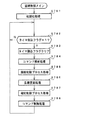
タイマ割込が発生すると、CPU56は、図20に示すステップS20〜S36のタイマ割込処理を実行する。タイマ割込処理において、まず、電源断信号が出力されたか否か(オン状態になったか否か)を検出する電源断検出処理を実行する(ステップS20)。電源断信号は、例えば電源基板に搭載されている電圧低下監視回路が、遊技機に供給される電源の電圧の低下を検出した場合に出力する。そして、電源断検出処理において、CPU56は、電源断信号が出力されたことを検出したら、必要なデータをバックアップRAM領域に保存するための電力供給停止時処理を実行する。次いで、入力ドライバ回路58を介して、ゲートスイッチ32a、第1始動口スイッチ13a、第2始動口スイッチ14a、カウントスイッチ23、および入賞口スイッチ29a,30a,33a,39aの検出信号を入力し、それらの状態判定を行う(スイッチ処理:ステップS21)。
When the timer interrupt occurs, the CPU 56 executes the timer interrupt process in steps S20 to S36 shown in FIG. In the timer interrupt process, first, a power-off detection process for detecting whether or not a power-off signal is output (whether or not an on-state is turned on) is executed (step S20). The power-off signal is output when, for example, a voltage drop monitoring circuit mounted on the power supply board detects a drop in the voltage of the power supplied to the gaming machine. In the power-off detection process, when detecting that the power-off signal has been output, the CPU 56 executes a power supply stop process for saving necessary data in the backup RAM area. Next, detection signals from the gate switch 32a, the first start port switch 13a, the second start port switch 14a, the count switch 23, and the winning
次に、CPU56は、特別図柄表示器8、普通図柄表示器10、特別図柄保留記憶表示器18、普通図柄保留記憶表示器41の表示制御を行う表示制御処理を実行する(ステップS22)。特別図柄表示器8および普通図柄表示器10については、ステップS34,S35で設定される出力バッファの内容に応じて各表示器に対して駆動信号を出力する制御を実行する。
Next, the CPU 56 executes display control processing for performing display control of the
また、CPU56は、正規の時期以外の時期において大入賞口に遊技球が入賞したことを検出した場合に異常入賞の報知を行わせるための処理を行う(ステップS23:異常入賞報知処理)。 Further, the CPU 56 performs a process for notifying an abnormal winning when it detects that a game ball has won a prize winning opening at a time other than the regular time (step S23: abnormal winning notifying process).
次に、遊技制御に用いられる大当り図柄決定用の乱数等の各判定用乱数を生成するための各カウンタのカウント値を更新する処理を行う(判定用乱数更新処理:ステップS24)。CPU56は、さらに、初期値用乱数および表示用乱数を生成するためのカウンタのカウント値を更新する処理を行う(初期値用乱数更新処理,表示用乱数更新処理:ステップS25,S26)。 Next, a process of updating the count value of each counter for generating each random number for determination such as a random number for determining jackpot symbols used for game control is performed (determination random number update process: step S24). The CPU 56 further performs a process of updating the count value of the counter for generating the initial value random number and the display random number (initial value random number update process, display random number update process: steps S25 and S26).
図21は、各乱数を示す説明図である。各乱数は、以下のように使用される。
(1)ランダム1:特別図柄のはずれ図柄(停止図柄)を決定する(はずれ図柄決定用)
(2)ランダム2:大当りを発生させるときの特別図柄の停止図柄を決定する(大当り図柄決定用)
(3)ランダム3:特別図柄の変動パターン(変動時間)を決定する(変動パターン決定用)
(4)ランダム4:普通図柄にもとづく当りを発生させるか否か決定する(普通図柄当り判定用)
(5)ランダム5:ランダム4の初期値を決定する(ランダム4初期値決定用)
FIG. 21 is an explanatory diagram showing each random number. Each random number is used as follows.
(1) Random 1: Decide a special symbol's off symbol (stop symbol) (for determining off symbol)
(2) Random 2: Determines the special symbol stop symbol when generating a big hit (for big hit symbol determination)
(3) Random 3: Determine the variation pattern (variation time) of special symbols (for variation pattern determination)
(4) Random 4: Determines whether or not to generate a hit based on the normal symbol (for normal symbol hit determination)
(5) Random 5:
図20に示された遊技制御処理におけるステップS24では、遊技制御用マイクロコンピュータ560は、(2)の大当り図柄決定用乱数、および(4)の普通図柄当り判定用乱数を生成するためのカウンタのカウントアップ(1加算)を行う。すなわち、それらが判定用乱数であり、それら以外の乱数が表示用乱数または初期値用乱数である。なお、遊技効果を高めるために、上記(1)〜(5)の乱数以外の乱数も用いるようにしてもよい。また、この実施の形態では、大当り判定用乱数は遊技制御用マイクロコンピュータ560に内蔵されたハードウェア(乱数回路)が生成する乱数であるが、大当り判定用乱数として、遊技制御用マイクロコンピュータ560によってプログラムにもとづいて生成されるソフトウェア乱数を用いてもよい。 In step S24 in the game control process shown in FIG. 20, the game control microcomputer 560 uses a counter for generating the jackpot symbol determination random number (2) and the random number for determination per regular symbol (4). Count up (add 1). That is, they are determination random numbers, and other random numbers are display random numbers or initial value random numbers. In addition, in order to improve a game effect, you may make it use random numbers other than the random number of said (1)-(5). In this embodiment, the big hit determination random number is a random number generated by the hardware (random number circuit) built in the game control microcomputer 560. However, the big hit determination random number is generated by the game control microcomputer 560 as the big hit determination random number. Software random numbers generated based on a program may be used.
さらに、CPU56は、特別図柄プロセス処理を行う(ステップS27)。特別図柄プロセス処理では、特別図柄表示器8および大入賞口を所定の順序で制御するための特別図柄プロセスフラグに従って該当する処理を実行する。CPU56は、特別図柄プロセスフラグの値を、遊技状態に応じて更新する。
Further, the CPU 56 performs special symbol process processing (step S27). In the special symbol process, the corresponding symbol is executed in accordance with a special symbol process flag for controlling the
次いで、普通図柄プロセス処理を行う(ステップS28)。普通図柄プロセス処理では、CPU56は、普通図柄表示器10の表示状態を所定の順序で制御するための普通図柄プロセスフラグに従って該当する処理を実行する。CPU56は、普通図柄プロセスフラグの値を、遊技状態に応じて更新する。
Next, normal symbol process processing is performed (step S28). In the normal symbol process, the CPU 56 executes a corresponding process according to the normal symbol process flag for controlling the display state of the
また、CPU56は、演出制御用マイクロコンピュータ100に演出制御コマンドを送出する処理を行う(演出制御コマンド制御処理:ステップS29)。なお、この実施の形態では、ステップS29において、遊技制御用マイクロコンピュータ560は、演出制御コマンドを構成するMODEデータまたはEXTデータ(送信先のシリアル−パラレル変換IC611〜619のアドレスが付加されたMODEデータまたはEXTデータ)に、ヘッダデータやマークビット、エンドビットを付加して送信制御を行う。そして、演出制御コマンドは、シリアル出力回路78によってシリアルデータに変換され、中継基板77を介して演出制御基板80に送信される。
Further, the CPU 56 performs a process of sending an effect control command to the effect control microcomputer 100 (effect control command control process: step S29). In this embodiment, in step S29, the game control microcomputer 560 causes the MODE data or EXT data (MODE data to which the addresses of the destination serial-
さらに、CPU56は、例えばホール管理用コンピュータに供給される大当り情報、始動情報、確率変動情報などのデータを出力する情報出力処理を行う(ステップS30)。 Further, the CPU 56 performs information output processing for outputting data such as jackpot information, start information, probability variation information supplied to the hall management computer, for example (step S30).
また、CPU56は、第1始動口スイッチ13a、第2始動口スイッチ14a、カウントスイッチ23および入賞口スイッチ29a,30a,33a,39aの検出信号にもとづく賞球個数の設定などを行う賞球処理を実行する(ステップS31)。具体的には、第1始動口スイッチ13a、第2始動口スイッチ14a、カウントスイッチ23および入賞口スイッチ29a,30a,33a,39aのいずれかがオンしたことにもとづく入賞検出に応じて、払出制御基板37に搭載されている払出制御用マイクロコンピュータに賞球個数を示す払出制御コマンド(賞球個数信号)を出力する。払出制御用マイクロコンピュータは、賞球個数を示す払出制御コマンドに応じて球払出装置97を駆動する。また、賞球処理では賞球エラーが発生したか否かの判定処理も行われる。例えば、賞球個数の設定値と実際の払出数とに食い違いが生じた場合に、CPU56は、賞球エラーが発生したと判定し、演出制御基板80が搭載する演出制御用マイクロコンピュータ100に、賞球エラーの発生を報知することを指定する賞球エラー報知指定コマンドを送信する制御を行う。
Further, the CPU 56 performs prize ball processing for setting the number of prize balls based on detection signals from the first start port switch 13a, the second start port switch 14a, the count switch 23, and the winning
また、CPU56は、満タンスイッチや球切れスイッチ、ドア開放センサ155の検出信号にもとづくエラー検出処理を実行する(ステップS32)。具体的には、満タンスイッチの検出信号に応じて、演出制御基板80に搭載されている演出制御用マイクロコンピュータ100に、満タンエラーが発生したことを報知することを指定する満タンエラー報知指定コマンドを送信する。また、球切れスイッチの検出信号に応じて、演出制御基板80に搭載されている演出制御用マイクロコンピュータ100に、球切れエラーが発生したことを報知することを指定する球切れエラー報知指定コマンドを送信する。ドア開放センサ155の検出信号に応じて、演出制御基板80に搭載されている演出制御用マイクロコンピュータ100に、ドア開放エラーが発生したことを報知することを指定するドア開放エラー報知指定コマンドを送信する。
Further, the CPU 56 executes an error detection process based on the detection signal from the full switch, the ball break switch, and the door opening sensor 155 (step S32). Specifically, a full tank error notification designation command for designating notification to the
この実施の形態では、出力ポートの出力状態に対応したRAM領域(出力ポートバッファ)が設けられているのであるが、CPU56は、出力ポートの出力状態に対応したRAM領域におけるソレノイドのオン/オフに関する内容を出力ポートに出力する(ステップS33:出力処理)。 In this embodiment, a RAM area (output port buffer) corresponding to the output state of the output port is provided. However, the CPU 56 relates to on / off of the solenoid in the RAM area corresponding to the output state of the output port. The contents are output to the output port (step S33: output process).
また、CPU56は、特別図柄プロセスフラグの値に応じて特別図柄の演出表示を行うための特別図柄表示制御データを特別図柄表示制御データ設定用の出力バッファに設定する特別図柄表示制御処理を行う(ステップS34)。CPU56は、例えば、特別図柄プロセス処理でセットされる開始フラグがセットされると終了フラグがセットされるまで、変動速度が1コマ/0.2秒であれば、0.2秒が経過する毎に、出力バッファに設定される表示制御データの値を+1する。また、CPU56は、出力バッファに設定された表示制御データに応じて、ステップS22において駆動信号を出力することによって、特別図柄表示器8における特別図柄の可変表示を実行する。
Further, the CPU 56 performs a special symbol display control process for setting special symbol display control data for effect display of special symbols in the output buffer for setting the special symbol display control data according to the value of the special symbol process flag ( Step S34). For example, if the change speed is 1 frame / 0.2 seconds until the end flag is set when the start flag set in the special symbol process is set, the CPU 56, for example, every 0.2 seconds passes. Then, the value of the display control data set in the output buffer is incremented by one. Further, the CPU 56 performs variable display of the special symbol on the
さらに、CPU56は、普通図柄プロセスフラグの値に応じて普通図柄の演出表示を行うための普通図柄表示制御データを普通図柄表示制御データ設定用の出力バッファに設定する普通図柄表示制御処理を行う(ステップS35)。CPU56は、例えば、普通図柄の変動に関する開始フラグがセットされると終了フラグがセットされるまで、普通図柄の変動速度が0.2秒ごとに表示状態(「○」および「×」)を切り替えるような速度であれば、0.2秒が経過する毎に、出力バッファに設定される表示制御データの値(例えば、「○」を示す1と「×」を示す0)を切り替える。また、CPU56は、出力バッファに設定された表示制御データに応じて、ステップS22において駆動信号を出力することによって、普通図柄表示器10における普通図柄の演出表示を実行する。
Further, the CPU 56 performs a normal symbol display control process for setting normal symbol display control data for effect display of the normal symbol in an output buffer for setting the normal symbol display control data according to the value of the normal symbol process flag ( Step S35). For example, when the start flag related to the variation of the normal symbol is set, the CPU 56 switches the display state (“◯” and “×”) for the variation rate of the normal symbol every 0.2 seconds until the end flag is set. With such a speed, the value of the display control data set in the output buffer (for example, 1 indicating “◯” and 0 indicating “x”) is switched every 0.2 seconds. Further, the CPU 56 outputs a normal signal on the
その後、割込許可状態に設定し(ステップS36)、処理を終了する。 Thereafter, the interrupt permission state is set (step S36), and the process ends.
以上の制御によって、この実施の形態では、遊技制御処理は2ms毎に起動されることになる。なお、遊技制御処理は、タイマ割込処理におけるステップS21〜S35(ステップS30を除く。)の処理に相当する。また、この実施の形態では、タイマ割込処理で遊技制御処理が実行されているが、タイマ割込処理では例えば割込が発生したことを示すフラグのセットのみがなされ、遊技制御処理はメイン処理において実行されるようにしてもよい。 With the above control, in this embodiment, the game control process is started every 2 ms. The game control process corresponds to the processes in steps S21 to S35 (excluding step S30) in the timer interrupt process. In this embodiment, the game control process is executed by the timer interrupt process. However, in the timer interrupt process, for example, only a flag indicating that an interrupt has occurred is set, and the game control process is performed by the main process. May be executed.
図22は、大当り判定テーブルを示す説明図である。大当り判定テーブルとは、ランダムRと比較される大当り判定値が設定されているテーブルである。大当り判定判定テーブルには、通常状態(確変状態でない遊技状態)において用いられる通常時大当り判定テーブル(図22(A)参照)と、確変状態において用いられる確変時大当り判定テーブル(図22(B)参照)とがある。図22(A),(B)の左欄に記載されている数値が大当り判定値である。CPU56は、ランダムRの値がいずれかの大当り判定値と一致すると、大当りとすることに決定する。CPU56は、所定の時期に、乱数回路のカウント値を抽出して抽出値を大当り判定用乱数値とするのであるが、大当り判定用乱数値が図21に示す大当り判定値に一致すると、特別図柄に関して大当り(確変大当りまたは通常大当り)とすることに決定する。 FIG. 22 is an explanatory diagram of a jackpot determination table. The jackpot determination table is a table in which a jackpot determination value to be compared with the random R is set. The jackpot determination determination table includes a normal jackpot determination table (see FIG. 22A) used in a normal state (a gaming state that is not a probability change state) and a probability change jackpot determination table (FIG. 22B) used in a probability change state. See). The numerical values described in the left column of FIGS. 22A and 22B are jackpot determination values. When the value of the random R matches any one of the jackpot determination values, the CPU 56 determines that the jackpot is to be made. The CPU 56 extracts the count value of the random number circuit at a predetermined time and uses the extracted value as the jackpot determination random value. If the jackpot determination random value matches the jackpot determination value shown in FIG. Is determined to be a big hit (probable big hit or normal big hit).
確変大当りとは、大当り遊技後の遊技状態を、通常状態に比べて大当りとすることに決定される確率が高い状態である確変状態に移行させるような大当りである。通常大当りとは、大当り遊技後の遊技状態を確変状態ではない状態に移行させるような大当りである。なお、確変大当りおよび通常大当りの場合には、ラウンド数は、小当りおよび突然確変大当りの場合よりも多く、例えば15ラウンドである。 The probability variation jackpot is a jackpot that shifts the gaming state after the jackpot game to a probability variation state in which there is a high probability of being determined to be a jackpot compared to the normal state. Usually, the big hit is a big hit that shifts the gaming state after the big hit game to a state that is not a probable change state. Note that the number of rounds in the case of a probable big hit and the normal big hit is larger than that in the case of a small hit and a sudden probable big hit, for example, 15 rounds.
小当りとは、大当り遊技状態において大入賞口の開放回数が2回まで許容される大当りである。なお、小当り遊技が終了した場合、遊技状態が確変状態に移行することはない。突然確変大当りとは、大当り遊技状態において大入賞口の開放回数が2回まで許容されるが大入賞口の開放時間が極めて短い大当りであり、かつ、大当り遊技後の遊技状態を確変状態に移行させるような大当りである。つまり、この実施の形態では、突然確変大当りと小当りとは、ラウンド数が同じである。 The small hit is a big hit in which the number of times of opening of the big winning opening is allowed up to two in the big hit gaming state. Note that when the small hit game ends, the gaming state does not shift to the probable change state. Suddenly probable jackpot is a jackpot where the number of times the big prize opening is allowed is 2 in the big hit gaming state, but the opening time of the big prize opening is extremely short, and the gaming state after the big hit game is shifted to the probable state It ’s a big hit. That is, in this embodiment, the number of rounds is the same between the sudden probability big hit and the small hit.
なお、突然確変大当りの大当り遊技では、ラウンド数は、通常大当りおよび確変大当りの場合よりも少なく、かつ、各ラウンドの大入賞口開放許容時間(例えば、通常大当りおよび確変大当りの場合の29秒に対して、0.5秒)は通常大当りおよび確変大当りの場合よりも短いが、ラウンド数のみを少なくしたり、大入賞口開放許容時間のみを短くするようにしてもよい。 In the big hit game of sudden probability change big hit, the number of rounds is smaller than in the case of normal big hit and probability variable big hit, and the allowance opening time for each round (for example, 29 seconds in the case of normal big hit and probability variable big hit) On the other hand, 0.5 seconds) is shorter than the case of the normal big hit and the probability variation big hit, but only the number of rounds may be reduced, or only the allowance opening allowance time may be shortened.
図23は、この実施の形態で用いられる変動パターンの一例を示す説明図である。後述するように、この実施の形態では、演出制御コマンドは2バイト構成であり、1バイト目はMODE(コマンドの分類)を表し、2バイト目はEXT(コマンドの種類)を表す。図23において、「EXT」とは、2バイト構成の演出制御コマンドにおける2バイト目のEXTデータを示す。また、「変動時間」は特別図柄の変動時間(識別情報の可変表示期間)を示す。 FIG. 23 is an explanatory diagram showing an example of a variation pattern used in this embodiment. As will be described later, in this embodiment, the presentation control command has a 2-byte structure, the first byte represents MODE (command classification), and the second byte represents EXT (command type). In FIG. 23, “EXT” indicates EXT data of the second byte in the effect control command having a two-byte structure. “Variation time” indicates the variation time of the special symbol (variable display period of identification information).
「通常変動」は、リーチ態様を伴わない変動パターンである。「通常変動・短縮」は、リーチ態様を伴わない変動パターンであり、かつ、変動時間が「通常変動」よりも短い変動パターンである。「ノーマルリーチ」は、リーチ態様を伴うが表示結果(停止図柄)が大当り図柄にならない変動パターンである。「リーチA」は、「ノーマルリーチ」とは異なるリーチ態様を持つ変動パターンである。リーチ態様が異なるとは、リーチ変動時間(リーチ演出が行われる期間)で可変表示装置9において異なった態様の変動態様(速度や回転方向等)やキャラクタ画像等が現れたり、可変表示装置9における背景図柄が異なることをいう。例えば、「ノーマルリーチ」では単に1種類の変動態様によってリーチ態様が実現されるのに対して、「リーチA」では、変動速度や変動方向が異なる複数の変動態様を含むリーチ態様が実現される。また、「リーチA・短縮」は、「リーチA」に類似したリーチ態様を持つ変動パターンであるが、リーチ変動時間は、「リーチA」に比べて短い。「リーチA・延長」は、「リーチA」に類似したリーチ態様を持つ変動パターンであるが、リーチ変動時間は、「リーチA」に比べて長い。
“Normal fluctuation” is a fluctuation pattern without a reach mode. “Normal fluctuation / shortening” is a fluctuation pattern without a reach mode and a fluctuation time shorter than “normal fluctuation”. “Normal reach” is a variation pattern that is accompanied by a reach mode but whose display result (stop symbol) does not become a big hit symbol. “Reach A” is a variation pattern having a reach form different from “normal reach”. A different reach mode means that a different mode of change mode (speed, direction of rotation, etc.), a character image, or the like appears in the
「リーチB」は、「ノーマルリーチ」および「リーチA」とは異なるリーチ態様を持つ変動パターンである。また、「リーチB・短縮」は、「リーチB」に類似したリーチ態様を持つ変動パターンであるが、リーチ変動時間は、「リーチB」に比べて短い。「リーチB・延長」は、「リーチB」に類似したリーチ態様を持つ変動パターンであるが、リーチ変動時間は、「リーチB」に比べて長い。「リーチC」は、「ノーマルリーチ」、「リーチA」および「リーチB」とは異なるリーチ態様を持つ変動パターンである。「リーチC・短縮」は、「リーチC」に類似したリーチ態様を持つ変動パターンであるが、リーチ変動時間は、「リーチC」に比べて短い。 “Reach B” is a fluctuation pattern having a reach mode different from “Normal reach” and “Reach A”. Further, “reach B / shortening” is a variation pattern having a reach manner similar to “reach B”, but the reach variation time is shorter than “reach B”. “Reach B / extension” is a variation pattern having a reach manner similar to “reach B”, but reach variation time is longer than “reach B”. “Reach C” is a variation pattern having a reach form different from “normal reach”, “reach A”, and “reach B”. “Reach C / shortening” is a variation pattern having a reach manner similar to “reach C”, but reach variation time is shorter than “reach C”.
また、「スーパーリーチA」は、「ノーマルリーチ」、「リーチA」、「リーチB」および「リーチC」とは異なるリーチ態様を持つ変動パターンであり、例えば動画像によるリーチ態様を持つ変動パターンである。「スーパーリーチB」は、「ノーマルリーチ」、「リーチA」、「リーチB」、「リーチC」および「スーパーリーチA」とは異なるリーチ態様を持つ変動パターンであり、例えば動画像によるリーチ態様を持つ変動パターンである。「リーチA・突確」は、「ノーマルリーチ」、「リーチA」、「リーチB」、「リーチC」、「スーパーリーチA」および「スーパーリーチB」とは異なるリーチ態様を持つ変動パターンである。なお、「リーチA・突確」のリーチ態様は、「リーチA」に類似するリーチ態様である。 “Super reach A” is a variation pattern having a reach mode different from “normal reach”, “reach A”, “reach B”, and “reach C”. is there. “Super reach B” is a variation pattern having a reach form different from “normal reach”, “reach A”, “reach B”, “reach C” and “super reach A”. This is a variation pattern. “Reach A / Accuracy” is a variation pattern having a reach form different from “Normal reach”, “Reach A”, “Reach B”, “Reach C”, “Super reach A” and “Super reach B”. It should be noted that the reach form of “reach A / accuracy” is a reach form similar to “reach A”.
この実施の形態では、通常大当りの場合には、遊技制御用マイクロコンピュータ560は、「リーチA・短縮」、「リーチA」、「リーチB・短縮」、「リーチB」、「リーチC・短縮」、「リーチC」、「スーパーリーチA」または「スーパーリーチB」を選択する。また、確変大当りの場合には、遊技制御用マイクロコンピュータ560は、「リーチA・延長」、「リーチB・延長」、「リーチC・短縮」、「リーチC」、「スーパーリーチA」または「スーパーリーチB」を選択する。突然確変大当りの場合には、「リーチA・突確」を選択する。 In this embodiment, in the case of a big hit, the game control microcomputer 560 is “reach A / shortening”, “reach A”, “reach B / shortening”, “reach B”, “reach C / shortening”. ", Reach C", "Super Reach A" or "Super Reach B". Further, in the case of a probable big hit, the game control microcomputer 560 is “reach A / extension”, “reach B / extension”, “reach C / shortening”, “reach C”, “super reach A” or “ Select "Super Reach B". In case of sudden big odds, select “Reach A / Random”.
また、図23に示すように、通常大当りの場合にのみ選択される変動パターンと、確変大当りの場合にのみ選択される変動パターンと、通常大当りのときにも確変大当りのときにも選択されうる変動パターンとがある。 Further, as shown in FIG. 23, the fluctuation pattern selected only in the case of the normal big hit, the fluctuation pattern selected only in the case of the probability big hit, and the normal big hit and the probability variable big hit can be selected. There are fluctuation patterns.
また、時短状態では、「通常変動・短縮」、「リーチA・短縮」、「リーチB・短縮」、および「リーチC・短縮」の変動パターンが選択される。非時短状態では、それ以外の変動パターンが選択される。ただし、「リーチA・突確」の変動パターンは、時短状態でも非時短状態でも使用される。 In the short-time state, the fluctuation patterns of “normal fluctuation / shortening”, “reach A / shortening”, “reach B / shortening”, and “reach C / shortening” are selected. In the non-time-short state, other variation patterns are selected. However, the variation pattern of “reach A / accuracy” is used in both the short-time state and the non-short-time state.
なお、この実施の形態では、大当りが発生し、大当り遊技が終了すると、その後、100回の特別図柄の変動(可変表示)の実行が完了するまで、遊技状態は時短状態になる。また、可変表示が終了すると大当り遊技が開始されるときの特別図柄の可変表示を開始するときに、確変状態にすることに決定された場合には、大当り遊技が終了すると遊技状態が確変状態に移行される。なお、そのときの遊技状態が確変状態であれば、確変状態が継続することになる。 In this embodiment, when a big hit occurs and the big hit game ends, the gaming state becomes a short-time state thereafter until the execution of 100 special symbol changes (variable display) is completed. In addition, when variable display of a special symbol is started when variable display is finished, when it is decided to change to a probable change state when the special symbol variable display is started, the game state is changed into a probable change state when the big hit game is ended. Migrated. If the gaming state at that time is a probability variation state, the probability variation state is continued.
確変状態に移行されたら、その後、100回の特別図柄の変動(可変表示)の実行が完了するまでは、確変状態かつ時短状態である。また、大当り遊技が終了した後の非確変状態において、100回の特別図柄の変動(可変表示)の実行が完了すると遊技状態は通常状態(確変状態でなく、かつ、時短状態でない遊技状態)に移行する。 After the transition to the probability changing state, the state of the probability changing state is short and the state is short until the execution of the variation (variable display) of 100 special symbols is completed. In addition, in the non-probability change state after the big hit game is over, the game state is changed to the normal state (the game state that is not the probability change state and not the short-time state) when the execution of 100 special symbol changes (variable display) is completed. Transition.
次に、遊技制御用マイクロコンピュータ560から演出制御用マイクロコンピュータ100に対する制御コマンドの送出方式について説明する。この実施の形態では、演出制御コマンドは、シリアル出力回路78によってパラレルデータからシリアルデータに変換され、主基板31から中継基板77を介して演出制御基板80に送信される。
Next, a method for sending a control command from the game control microcomputer 560 to the
この実施の形態では、演出制御コマンドは2バイト構成であり、1バイト目はMODE(コマンドの分類)を表し、2バイト目はEXT(コマンドの種類)を表す。MODEデータの先頭ビット(ビット7)は必ず「1」に設定され、EXTデータの先頭ビット(ビット7)は必ず「0」に設定される。なお、そのようなコマンド形態は一例であって他のコマンド形態を用いてもよい。例えば、1バイトや3バイト以上で構成される制御コマンドを用いてもよい In this embodiment, the presentation control command has a 2-byte structure, the first byte represents MODE (command classification), and the second byte represents EXT (command type). The first bit (bit 7) of the MODE data is always set to “1”, and the first bit (bit 7) of the EXT data is always set to “0”. Note that such a command form is an example, and other command forms may be used. For example, a control command composed of 1 byte or 3 bytes or more may be used.
図24は、シリアルデータ方式として送信される演出制御コマンドのフォーマットの例を示す説明図である。図24に示すように、演出制御コマンドを送信する際、遊技制御用マイクロコンピュータ560(具体的にはCPU56)は、まず、MODEデータ(アドレスが付加されたMODEデータ)にヘッダデータやマークビット、エンドビットを付加して送信制御を行う。すると、シリアル出力回路78は、ヘッダデータやアドレス、マークビット、エンドビットが付加されたMODEデータをシリアルデータに変換して、中継基板77を介して演出制御基板80に送信する。次いで、遊技制御用マイクロコンピュータ560は、EXTデータ(アドレスが付加されたEXTデータ)にヘッダデータやマークビット、エンドビットを付加して送信制御を行う。すると、シリアル出力回路78は、ヘッダデータやアドレス、マークビット、エンドビットが付加されたEXTデータをシリアルデータに変換して、中継基板77を介して演出制御基板80に送信する。
FIG. 24 is an explanatory diagram showing an example of the format of the effect control command transmitted as the serial data method. As shown in FIG. 24, when transmitting the effect control command, the game control microcomputer 560 (specifically, the CPU 56) first adds header data and mark bits to MODE data (MODE data to which an address is added), Transmission control is performed by adding an end bit. Then, the
図25は、遊技制御用マイクロコンピュータ560が送信する演出制御コマンドの内容の一例を示す説明図である。図25に示す例において、コマンド8001(H)〜800E(H)は、特別図柄の可変表示に対応して可変表示装置9において可変表示される飾り図柄の変動パターンを指定する演出制御コマンド(変動パターンコマンド)である。なお、変動パターンを指定する演出制御コマンドは、変動開始を指定するためのコマンドでもある。従って、演出制御用マイクロコンピュータ100は、コマンド8001(H)〜800E(H)のいずれかを受信すると、可変表示装置9において飾り図柄の可変表示を開始するように制御する。なお、この実施の形態では、特別図柄の可変表示と飾り図柄の可変表示とは同期(可変表示開始時期および可変表示終了時期が同じ。)しているので、飾り図柄の変動パターン(変動時間)を決定することは、特別図柄の変動パターン(変動時間)を決定することも意味する。
FIG. 25 is an explanatory diagram showing an example of the contents of the effect control command transmitted by the game control microcomputer 560. In the example shown in FIG. 25, commands 8001 (H) to 800E (H) are effect control commands (variation) for designating a variation pattern of decorative symbols that are variably displayed on the
コマンド8C01(H)〜8C05(H)は、大当りとするか否か、および大当り遊技の種類を示す演出制御コマンドである。演出制御用マイクロコンピュータ100は、コマンド8C01(H)〜8C05(H)の受信に応じて飾り図柄の表示結果を決定するので、コマンド8C01(H)〜8C05(H)を表示結果特定コマンドという。
The commands 8C01 (H) to 8C05 (H) are effect control commands indicating whether or not to make a big hit and the type of the big hit game. The
コマンド8F00(H)は、飾り図柄の可変表示(変動)を終了して表示結果(停止図柄)を導出表示することを示す演出制御コマンド(図柄確定指定コマンド)である。演出制御用マイクロコンピュータ100は、図柄確定指定コマンドを受信すると、飾り図柄の可変表示(変動)を終了して表示結果を導出表示する。なお、導出表示とは、図柄を最終的に停止表示させることである。
Command 8F00 (H) is an effect control command (symbol confirmation designation command) indicating that the variable display (fluctuation) of the decorative symbols is terminated and the display result (stop symbol) is derived and displayed. When receiving the symbol confirmation designation command, the
コマンド9000(H)は、遊技機に対する電力供給が開始されたときに送信される演出制御コマンド(初期化指定コマンド:電源投入指定コマンド)である。コマンド9200(H)は、遊技機に対する電力供給が再開されたときに送信される演出制御コマンド(停電復旧指定コマンド)である。遊技制御用マイクロコンピュータ560は、遊技機に対する電力供給が開始されたときに、バックアップRAMにデータが保存されている場合には、停電復旧指定コマンドを送信し、そうでない場合には、初期化指定コマンドを送信する。 Command 9000 (H) is an effect control command (initialization designation command: power-on designation command) transmitted when power supply to the gaming machine is started. Command 9200 (H) is an effect control command (power failure recovery designation command) transmitted when power supply to the gaming machine is resumed. When the power supply to the gaming machine is started, the game control microcomputer 560 transmits a power failure recovery designation command if data is stored in the backup RAM, and if not, initialization designation is performed. Send a command.
コマンド9F00(H)は、客待ちデモンストレーションを指定する演出制御コマンド(客待ちデモ指定コマンド)である。また、コマンド9F55(H)は、メイン処理における乱数回路確認処理において乱数回路の異常発生を検出した場合に、主基板31の乱数回路エラーを報知することを指定する演出制御コマンド(乱数回路エラー指定コマンド)である。
Command 9F00 (H) is an effect control command (customer waiting demonstration designation command) for designating a customer waiting demonstration. The command 9F55 (H) is an effect control command (random number circuit error designation) for designating notification of a random number circuit error of the
コマンドA001〜A004(H)は、ファンファーレ画面を表示すること、すなわち大当り遊技の開始を指定する演出制御コマンド(大当り開始指定コマンド:ファンファーレ指定コマンド)である。大当り開始指定コマンドには、大当りの種類に応じて、大当り開始1指定〜大当り開始指定4指定コマンドがある。コマンドA1XX(H)は、XXで示す回数目(ラウンド)の大入賞口開放中の表示を示す演出制御コマンド(大入賞口開放中指定コマンド)である。A2XX(H)は、XXで示す回数目(ラウンド)の大入賞口閉鎖を示す演出制御コマンド(大入賞口開放後指定コマンド)である。
The commands A001 to A004 (H) are effect control commands for displaying the fanfare screen, that is, designating the start of the big hit game (big hit start designation command: fanfare designation command). The jackpot start designation commands include jackpot start 1 designation to jackpot start
コマンドA301(H)は、大当り終了画面を表示すること、すなわち大当り遊技の終了を指定するとともに、非確変大当り(通常大当り)であったことを指定する演出制御コマンド(大当り終了1指定コマンド:エンディング1指定コマンド)である。コマンドA302(H)は、大当り終了画面を表示すること、すなわち大当り遊技の終了を指定するとともに、確変大当りであったことを指定する演出制御コマンド(大当り終了2指定コマンド:エンディング2指定コマンド)である。
Command A301 (H) displays a jackpot end screen, that is, specifies the end of the jackpot game, and also specifies an effect control command (
コマンドD001(H)は、異常入賞の報知を指示する演出制御コマンド(異常入賞報知指定コマンド)である。 Command D001 (H) is an effect control command (abnormal winning notification designation command) for instructing notification of abnormal winning.
コマンドFF02(H)は、下皿(余剰球受皿4)が満タン状態になった場合(すなわち、満タンスイッチがオン状態になった場合)に、満タンエラーが発生したことを報知することを指定する演出制御コマンド(満タンエラー報知指定コマンド)である。また、コマンドFF01(H)は、下皿の満タン状態が解除された場合(すなわち、満タンスイッチがオフ状態になった場合)に、満タンエラーの報知を解除することを指定する演出制御コマンド(満タンエラー解除指定コマンド)である。 The command FF02 (H) notifies that a full tank error has occurred when the lower pan (the surplus ball receiving tray 4) is full (that is, when the full tank switch is turned on). This is an effect control command to be designated (full error notification designation command). The command FF01 (H) is an effect control command for designating cancellation of the full-tan error notification when the full-plate state of the lower pan is released (that is, when the full-tan switch is turned off). (Full tank error release specification command).
コマンドFF04(H)は、遊技枠11が開放状態になった場合(すなわち、ドア開放センサ155の検出信号を検出した場合)に、ドア開放エラーが発生したことを報知することを指定する演出制御コマンド(ドア開放エラー報知指定コマンド)である。また、コマンドFF03(H)は、遊技枠11の開放状態が解除された場合に、ドア開放エラーの報知を解除することを指定する演出制御コマンド(ドア開放エラー解除指定コマンド)である。
The command FF04 (H) designates that when the
コマンドFF06(H)は、球切れ状態になった場合(すなわち、球切れスイッチがオン状態になった場合)に、球切れエラーが発生したことを報知することを指定する演出制御コマンド(球切れエラー報知指定コマンド)である。また、コマンドFF05(H)は、球切れ状態が解除された場合に、球切れエラーの報知を解除することを指定する演出制御コマンド(球切れエラー解除指定コマンド)である。 Command FF06 (H) is an effect control command (out of ball) that specifies that a ball out error has occurred when the ball is out of state (that is, when the ball out switch is turned on). Error notification designation command). The command FF05 (H) is an effect control command (ball-out error cancel designation command) that designates cancellation of the ball-out error notification when the ball-out state is released.
コマンドFF08(H)は、賞球エラーが発生した場合に、賞球エラーが発生したことを報知することを指定する演出制御コマンド(賞球エラー報知指定コマンド)である。また、コマンドFF07(H)は、賞球エラーが解除された場合に、賞球エラーの報知を解除することを指定する演出制御コマンド(賞球エラー解除指定コマンド)である。 The command FF08 (H) is an effect control command (prize ball error notification designation command) for designating notification that a prize ball error has occurred when a prize ball error has occurred. The command FF07 (H) is an effect control command (prize ball error cancel designation command) that designates canceling the notification of the prize ball error when the prize ball error is canceled.
演出制御基板80に搭載されている演出制御用マイクロコンピュータ100(具体的には、演出制御用CPU101)は、主基板31に搭載されている遊技制御用マイクロコンピュータ560から上述した演出制御コマンドを受信すると、図25に示された内容に応じて可変表示装置9の表示状態を変更したり、ランプの表示状態を変更したり、音声出力基板70に対して音番号データを出力したりする。
The effect control microcomputer 100 (specifically, the effect control CPU 101) mounted on the
図26は、演出制御コマンドの送信タイミングの一例を示す説明図である。図26に示すように、遊技制御用マイクロコンピュータ560は、変動開始時に、変動パターンコマンドおよび表示結果特定コマンドを送信する。そして、可変表示時間が経過すると、図柄確定指定コマンドを送信する。 FIG. 26 is an explanatory diagram showing an example of the transmission timing of the effect control command. As shown in FIG. 26, the game control microcomputer 560 transmits a change pattern command and a display result specifying command at the start of change. When the variable display time has elapsed, a symbol confirmation designation command is transmitted.
なお、変動パターンコマンドを送信する前に、遊技状態(例えば、通常状態/時短状態/確変状態)に応じた可変表示装置9における背景画像を指定する背景指定コマンドを送信するようにしてもよい。また、表示結果特定コマンドに続いて保留記憶数を示す演出制御コマンドを送信するようにしてもよい。
Before transmitting the variation pattern command, a background designation command for designating a background image in the
図27および図28は、主基板31に搭載される遊技制御用マイクロコンピュータ560(具体的には、CPU56)が実行する特別図柄プロセス処理(ステップS27)のプログラムの一例を示すフローチャートである。上述したように、特別図柄プロセス処理では特別図柄表示器8および大入賞口を制御するための処理が実行される。特別図柄プロセス処理において、CPU56は、始動入賞口13に遊技球が入賞したことを検出するための第1始動口スイッチ13aまたは第2始動口スイッチ14aがオンしていたら、すなわち始動入賞が発生していたら、始動口スイッチ通過処理を実行する(ステップS311,S312)。そして、ステップS300〜S310のうちのいずれかの処理を行う。
FIG. 27 and FIG. 28 are flowcharts showing an example of a program of special symbol process (step S27) executed by the game control microcomputer 560 (specifically, the CPU 56) mounted on the
ステップS300〜S310の処理は、以下のような処理である。 The processes in steps S300 to S310 are as follows.
特別図柄通常処理(ステップS300):特別図柄プロセスフラグの値が0であるときに実行される。遊技制御用マイクロコンピュータ560は、特別図柄の可変表示が開始できる状態になると、保留記憶数(始動入賞記憶数)を確認する。保留記憶数は保留記憶数カウンタのカウント値により確認できる。保留記憶数が0でない場合には、大当りとするか否か決定する。そして、内部状態(特別図柄プロセスフラグ)をステップS301に対応した値(この例では1)に更新する。 Special symbol normal processing (step S300): Executed when the value of the special symbol process flag is zero. When the game control microcomputer 560 is ready to start the variable display of the special symbol, it checks the number of reserved memories (the number of start winning memories). The reserved memory number can be confirmed by the count value of the reserved memory number counter. If the number of reserved memories is not 0, it is determined whether or not to win. Then, the internal state (special symbol process flag) is updated to a value (1 in this example) corresponding to step S301.
変動パターン設定処理(ステップS301):特別図柄プロセスフラグの値が1であるときに実行される。特別図柄の可変表示後の停止図柄を決定する。また、変動パターンを決定し、その変動パターンにおける変動時間(可変表示時間:可変表示を開始してから表示結果が導出表示(停止表示)するまでの時間)を特別図柄の可変表示の変動時間とすることに決定する。また、特別図柄の変動時間を計測する変動時間タイマをスタートさせる。そして、内部状態(特別図柄プロセスフラグ)をステップS302に対応した値(この例では2)に更新する。 Fluctuation pattern setting process (step S301): This process is executed when the value of the special symbol process flag is 1. The stop symbol after the variable display of the special symbol is determined. Also, the variation pattern is determined, and the variation time in the variation pattern (variable display time: the time from the start of variable display until the display result is derived and displayed (stop display)) Decide to do. Also, a variable time timer for measuring the special symbol variable time is started. Then, the internal state (special symbol process flag) is updated to a value (2 in this example) corresponding to step S302.
表示結果特定コマンド送信処理(ステップS302):特別図柄プロセスフラグの値が2であるときに実行される。演出制御用マイクロコンピュータ100に、表示結果特定コマンドを送信する制御を行う。そして、内部状態(特別図柄プロセスフラグ)をステップS303に対応した値(この例では3)に更新する。
Display result specifying command transmission process (step S302): executed when the value of the special symbol process flag is 2. Control for transmitting a display result specifying command to the
特別図柄変動中処理(ステップS303):特別図柄プロセスフラグの値が3であるときに実行される。変動パターン設定処理で選択された変動パターンの変動時間が経過(ステップS301でセットされる変動時間タイマがタイムアウトすなわち変動時間タイマの値が0になる)すると、内部状態(特別図柄プロセスフラグ)をステップS304に対応した値(この例では4)に更新する。 Special symbol changing process (step S303): This process is executed when the value of the special symbol process flag is 3. When the variation time of the variation pattern selected in the variation pattern setting process elapses (the variation time timer set in step S301 times out, that is, the variation time timer value becomes 0), the internal state (special symbol process flag) is stepped. Update to a value corresponding to S304 (4 in this example).
特別図柄停止処理(ステップS304):特別図柄プロセスフラグの値が4であるときに実行される。特別図柄表示器8における可変表示を停止して停止図柄を導出表示させる。また、演出制御用マイクロコンピュータ100に、図柄確定指定コマンドを送信する制御を行う。そして、大当りフラグがセットされ、かつ、小当りフラグがセットされていない場合には、内部状態(特別図柄プロセスフラグ)をステップS305に対応した値(この例では5)に更新する。小当りフラグがセットされている場合には、内部状態(特別図柄プロセスフラグ)をステップS308に対応した値(この例では8)に更新する。大当りフラグがセットされていない場合には、内部状態(特別図柄プロセスフラグ)をステップS300に対応した値(この例では0)に更新する。なお、演出制御用マイクロコンピュータ100は、遊技制御用マイクロコンピュータ560が送信する図柄確定指定コマンドを受信すると可変表示装置9において飾り図柄が停止されるように制御する。
Special symbol stop process (step S304): executed when the value of the special symbol process flag is 4. The variable display on the
大入賞口開放前処理(ステップS305):特別図柄プロセスフラグの値が5であるときに実行される。大入賞口開放前処理では、大入賞口を開放する制御を行う。具体的には、カウンタ(例えば大入賞口に入った遊技球数をカウントするカウンタ)などを初期化するとともに、ソレノイド21を駆動して大入賞口を開放状態にする。また、タイマによって大入賞口開放中処理の実行時間を設定し、内部状態(特別図柄プロセスフラグ)をステップS306に対応した値(この例では6)に更新する。なお、大入賞口開放前処理は各ラウンド毎に実行されるが、第1ラウンドを開始する場合には、大入賞口開放前処理は大当り遊技を開始する処理でもある。
Preliminary winning opening opening process (step S305): This is executed when the value of the special symbol process flag is 5. In the pre-opening process for the big prize opening, control for opening the big prize opening is performed. Specifically, a counter (for example, a counter that counts the number of game balls that have entered the big prize opening) is initialized, and the
大入賞口開放中処理(ステップS306):特別図柄プロセスフラグの値が6であるときに実行される。大当り遊技状態中のラウンド表示の演出制御コマンドを演出制御用マイクロコンピュータ100に送信する制御や大入賞口の閉成条件の成立を確認する処理等を行う。大入賞口の閉成条件が成立し、かつ、まだ残りラウンドがある場合には、内部状態(特別図柄プロセスフラグ)をステップS305に対応した値(この例では5)に更新する。また、全てのラウンドを終えた場合には、内部状態(特別図柄プロセスフラグ)をステップS307に対応した値(この例では7)に更新する。
Large winning opening opening process (step S306): This process is executed when the value of the special symbol process flag is 6. A control for transmitting an effect control command for round display during the big hit gaming state to the
大当り終了処理(ステップS307):特別図柄プロセスフラグの値が7であるときに実行される。大当り遊技状態が終了したことを遊技者に報知する表示制御を演出制御用マイクロコンピュータ100に行わせるための制御を行う。また、遊技状態を示すフラグ(例えば、確変フラグ)をセットする処理を行う。そして、内部状態(特別図柄プロセスフラグ)をステップS300に対応した値(この例では0)に更新する。
Big hit end process (step S307): executed when the value of the special symbol process flag is 7. Control is performed to cause the
小当り開放前処理(ステップS308):特別図柄プロセスフラグの値が8であるときに実行される。小当り開放前処理では、大入賞口を開放する制御を行う。具体的には、カウンタ(例えば大入賞口に入った遊技球数をカウントするカウンタ)などを初期化するとともに、ソレノイド21を駆動して大入賞口を開放状態にする。また、タイマによって大入賞口開放中処理の実行時間を設定し、内部状態(特別図柄プロセスフラグ)をステップS309に対応した値(この例では9)に更新する。なお、小当り開放前処理は各ラウンド毎に実行されるが、第1ラウンドを開始する場合には、小当り開放前処理は小当り遊技を開始する処理でもある。
Small hit release pre-processing (step S308): This process is executed when the value of the special symbol process flag is 8. In the pre-opening process for small hits, control is performed to open the big prize opening. Specifically, a counter (for example, a counter that counts the number of game balls that have entered the big prize opening) is initialized, and the
小当り開放中処理(ステップS309):特別図柄プロセスフラグの値が9であるときに実行される。小当り遊技状態中のラウンド表示の演出制御コマンドを演出制御用マイクロコンピュータ100に送信する制御や大入賞口の閉成条件の成立を確認する処理等を行う。大入賞口の閉成条件が成立し、かつ、まだ残りラウンドがある場合には、内部状態(特別図柄プロセスフラグ)をステップS308に対応した値(この例では8)に更新する。また、全てのラウンドを終えた場合には、内部状態(特別図柄プロセスフラグ)をステップS310に対応した値(この例では10(10進数))に更新する。
Small hit release processing (step S309): executed when the value of the special symbol process flag is 9. A control for transmitting an effect control command for a round display during the small hit gaming state to the
小当り終了処理(ステップS310):特別図柄プロセスフラグの値が10であるときに実行される。小当り遊技状態が終了したことを遊技者に報知する表示制御を演出制御用マイクロコンピュータ100に行わせるための制御を行う。そして、内部状態(特別図柄プロセスフラグ)をステップS300に対応した値(この例では0)に更新する。
Small hit end process (step S310): executed when the value of the special symbol process flag is 10. Control is performed to cause the
図29は、ステップS312の始動口スイッチ通過処理を示すフローチャートである。始動口スイッチ通過処理において、CPU56は、保留記憶数が上限値である4になっているか否か確認する(ステップS211)。保留記憶数が4になっている場合には、処理を終了する。 FIG. 29 is a flowchart showing the start port switch passing process in step S312. In the start port switch passing process, the CPU 56 checks whether or not the reserved storage number is 4 which is the upper limit value (step S211). If the number of reserved memories is 4, the process is terminated.
保留記憶数が4になっていない場合には、保留記憶数を示す保留記憶数カウンタの値を1増やす(ステップS212)。また、CPU56は、ソフトウェア乱数(大当り図柄決定用乱数等を生成するためのカウンタの値等)およびランダムR(大当り判定用乱数)を抽出し、それらを、抽出した乱数値として保留記憶数カウンタの値に対応する保留記憶バッファにおける保存領域に格納する処理を実行する(ステップS213)。ステップS213では、CPU56は、ソフトウェア乱数としてランダム1〜3(図21参照)の値を抽出し、乱数回路のカウント値を読み出すことによってランダムRを抽出する。また、保留記憶バッファにおいて、保存領域は、保留記憶数の上限値と同数確保されている。また、大当り図柄決定用乱数等を生成するためのカウンタや保留記憶バッファは、RAM55に形成されている。「RAMに形成されている」とは、RAM内の領域であることを意味する。
If the number of reserved memories is not 4, the value of the reserved memory number counter indicating the number of reserved memories is incremented by 1 (step S212). Further, the CPU 56 extracts software random numbers (counter value for generating a big hit symbol determination random number, etc.) and random R (big hit determination random number), and uses them as an extracted random number value of the reserved memory number counter. A process of storing in the storage area in the storage buffer corresponding to the value is executed (step S213). In step S213, the CPU 56 extracts
図30および図31は、特別図柄プロセス処理における特別図柄通常処理(ステップS300)を示すフローチャートである。特別図柄通常処理において、CPU56は、保留記憶数の値を確認する(ステップS51)。具体的には、保留記憶数カウンタのカウント値を確認する。保留記憶数が0であれば処理を終了する。 30 and 31 are flowcharts showing the special symbol normal process (step S300) in the special symbol process. In the special symbol normal process, the CPU 56 checks the value of the number of reserved storage (step S51). Specifically, the count value of the pending storage number counter is confirmed. If the number of reserved memories is 0, the process is terminated.
保留記憶数が0でなければ、CPU56は、RAM55の保留記憶数バッファにおける保留記憶数=1に対応する保存領域に格納されている各乱数値を読み出してRAM55の乱数バッファ領域に格納する(ステップS52)。そして、保留記憶数の値を1減らし(保留記憶数カウンタのカウント値を1減算し)、かつ、各保存領域の内容をシフトする(ステップS53)。すなわち、RAM55の保留記憶数バッファにおいて保留記憶数=n(n=2,3,4)に対応する保存領域に格納されている各乱数値を、保留記憶数=n−1に対応する保存領域に格納する。よって、各保留記憶数に対応するそれぞれの保存領域に格納されている各乱数値が抽出された順番は、常に、保留記憶数=1,2,3,4の順番と一致するようになっている。
If the reserved memory number is not 0, the CPU 56 reads each random number value stored in the storage area corresponding to the reserved memory number = 1 in the reserved memory number buffer of the
そして、CPU56は、乱数バッファ領域からランダムR(大当り判定用乱数)を読み出し(ステップS61)、大当り判定モジュールを実行する(ステップS62)。大当り判定モジュールは、あらかじめ決められている大当り判定値(図22参照)と大当り判定用乱数とを比較し、それらが一致したら大当り(通常大当り、確変大当りまたは突然確変大当り)または小当りとすることに決定する処理を実行するプログラムである。 Then, the CPU 56 reads a random R (a jackpot determination random number) from the random number buffer area (step S61), and executes a jackpot determination module (step S62). The big hit judgment module compares the big hit judgment value (see Fig. 22) determined in advance with the big hit judgment random number, and if they match, the big hit (normal big hit, probability variation big hit or sudden probability variation big hit) or small hit This is a program for executing the process to be determined.
なお、CPU56は、遊技状態が確変状態であるときには、図22(B)に示すような大当り判定値が設定されているテーブルにおける大当り判定値を使用し、遊技状態が通常状態(非確変状態)であるときには、図22(A)に示すような大当り判定値が設定されているテーブルにおける大当り判定値を使用する。大当りとすることに決定した場合には(ステップS63)、ステップS81に移行する。なお、大当りとするか否か決定するということは、大当り遊技状態に移行させるか否か決定するということであるが、特別図柄表示器8における停止図柄を大当り図柄とするか否か決定するということでもある。 Note that, when the gaming state is in the probability variation state, the CPU 56 uses the jackpot determination value in the table in which the jackpot determination value as shown in FIG. 22B is set, and the gaming state is in the normal state (non-probability variation state). Is, the jackpot determination value in the table in which the jackpot determination value as shown in FIG. 22 (A) is set is used. If it is determined to be a big hit (step S63), the process proceeds to step S81. Note that deciding whether or not to make a big hit means deciding whether or not to shift to the big win gaming state, but deciding whether or not to make the stop symbol in the special symbol display 8 a big hit symbol. It is also a thing.
大当りとしないことに決定した場合には、CPU56は、乱数バッファ領域からはずれ図柄決定用乱数を読み出し(ステップS64)、はずれ図柄決定用乱数にもとづいて停止図柄を決定する(ステップS65)。この場合には、はずれ図柄(例えば、偶数図柄のいずれか)を決定する。 If it is decided not to win, the CPU 56 reads out the design symbol random number from the random number buffer area (step S64), and determines the stop symbol based on the design symbol random number (step S65). In this case, an off symbol (for example, any of even symbols) is determined.
さらに、時短状態であることを示す時短フラグがセットされている場合には(ステップS66)、時短状態における特別図柄の変動可能回数を示す時短回数カウンタの値を−1する(ステップS67)。そして、時短回数カウンタの値が0になった場合には、可変表示が終了したときに遊技状態を非時短状態に移行させるために時短終了フラグをセットする(ステップS68,S69)。そして、ステップS90に移行する。 Further, when the time reduction flag indicating the time reduction state is set (step S66), the value of the time reduction counter indicating the number of times the special symbol can be changed in the time reduction state is decremented by 1 (step S67). When the value of the time reduction counter becomes 0, a time reduction end flag is set in order to shift the gaming state to the non-time reduction state when the variable display ends (steps S68 and S69). Then, the process proceeds to step S90.
ステップS81では、CPU56は、大当りフラグをセットする。そして、乱数バッファ領域から大当り図柄決定用乱数を読み出し(ステップS82)、大当り図柄決定用乱数にもとづいて停止図柄としての大当り図柄(例えば、奇数図柄のいずれか)を決定する(ステップS83)。なお、ここでは、確変大当りと通常大当りとを区別せずに停止図柄を決定する。 In step S81, the CPU 56 sets a big hit flag. Then, the big hit symbol determination random number is read from the random number buffer area (step S82), and the big hit symbol (for example, one of the odd symbols) as the stop symbol is determined based on the big hit symbol determination random number (step S83). Here, the stop symbol is determined without distinguishing between the probable big hit and the normal big hit.
次いで、CPU56は、確変大当りとすることに決定されている場合には、確変大当りフラグをセットする(ステップS84,S85)。また、突然確変大当りとすることに決定されている場合には、突然確変大当りフラグをセットする(ステップS86,S87)。また、小当りとすることに決定されている場合には、小当りフラグをセットする(ステップS88,S89)。そして、特別図柄プロセスフラグの値を変動パターン設定処理(ステップS301)に対応した値に更新する(ステップS90)。なお、確変大当りフラグまたは突然確変大当りフラグがセットされた場合には、大当り遊技が終了したときに遊技状態が確変状態に移行される。 Next, the CPU 56 sets a probability variation jackpot flag if it is determined to be a probability variation jackpot (steps S84 and S85). If it is determined that the sudden probability change big hit is suddenly set, the sudden probability change big hit flag is set (steps S86 and S87). If it is determined to be a small hit, a small hit flag is set (steps S88 and S89). Then, the value of the special symbol process flag is updated to a value corresponding to the variation pattern setting process (step S301) (step S90). When the probability variation big hit flag or the sudden probability variation big hit flag is set, the gaming state is shifted to the probability changing state when the big hit game is finished.
なお、この実施の形態では、大当り判定用乱数にもとづいて、大当りとするか否かと大当りの種類とを決定するようにしているが(図22参照)、大当り判定用乱数にもとづいて大当りとするか否かを決定し、大当りとすることに決定された場合に大当り図柄決定用乱数にもとづいて所定の大当り図柄(あらかじめ決められている確変大当り図柄や突然確変大当り図柄)が決定されたときに確変状態に制御するようにしてもよい。 In this embodiment, whether or not to make a big hit and the type of jackpot are determined based on the big hit determination random number (see FIG. 22), but the big hit is determined based on the big hit determination random number. When a predetermined jackpot symbol (predetermined probability variation jackpot symbol or sudden probability variation jackpot symbol) is determined based on the random number for determining the jackpot symbol when it is determined to be a jackpot You may make it control to a probability change state.
図32は、特別図柄プロセス処理における変動パターン設定処理(ステップS301)を示すフローチャートである。変動パターン設定処理において、CPU56は、乱数バッファ領域から変動パターン決定用乱数を読み出す(ステップS100)。そして、変動パターン決定用乱数にもとづいて変動パターンを決定する(ステップS101)。 FIG. 32 is a flowchart showing the variation pattern setting process (step S301) in the special symbol process. In the variation pattern setting process, the CPU 56 reads the variation pattern determination random number from the random number buffer area (step S100). Then, the variation pattern is determined based on the variation pattern determination random number (step S101).
ここで、遊技状態が非時短状態であって、はずれとすることに決定されている場合には、「通常変動」または「ノーマルリーチ」を選択する(図23参照)。遊技状態が非時短状態であって、大当りとすることに決定されている場合には、「リーチA」、「リーチA・延長」、「リーチB」、「リーチB・延長」、「リーチC」、「スーパーリーチA」、「スーパーリーチB」または「リーチA・突確」を選択する(図23参照)。大当りのうち確変大当りとすることに決定されている場合に、「リーチA・延長」、「リーチB・延長」、「リーチC」、「スーパーリーチA」または「スーパーリーチB」を選択する。また、突然確変大当りとすることに決定されている場合に、「リーチA・突確」を選択する。大当りのうち通常大当り(小当りとすることに決定されている場合を含む。)とすることに決定されている場合(小当りとすることに決定されている場合を含む。)には、「リーチA」、「リーチB」、「リーチC」または「スーパーリーチA」を選択する。 Here, when the gaming state is the non-time saving state and it is determined to be out of play, “normal variation” or “normal reach” is selected (see FIG. 23). If the gaming state is a non-time-saving state and it is determined to be a big hit, “reach A”, “reach A / extension”, “reach B”, “reach B / extension”, “reach C” ”,“ Super Reach A ”,“ Super Reach B ”or“ Reach A · Accuracy ”(see FIG. 23). When it is determined to be a promising big hit out of the big hits, “reach A / extension”, “reach B / extension”, “reach C”, “super reach A” or “super reach B” is selected. In addition, when it is determined that the sudden probability change is a big hit, “reach A / accuracy” is selected. If it is determined to be a big hit (including the case where it is determined to be a small hit) among the big hits (including the case where it is determined to be a small hit), “ Select Reach A, Reach B, Reach C, or Super Reach A.
遊技状態が時短状態であって、はずれとすることに決定されている場合には、「通常変動・短縮」を選択する(図23参照)。遊技状態が時短状態であって、大当りとすることに決定されている場合には、「リーチA・短縮」、「リーチB・短縮」、「リーチC・短縮」または「リーチA・突確」を選択する(図23参照)。大当りのうち確変大当りとすることに決定されている場合に、「リーチC・短縮」を選択する。突然確変大当りとすることに決定されている場合に、「リーチA・突確」を選択する。大当りのうち通常大当りとすることに決定されている場合(小当りとすることに決定されている場合を含む。)には、「リーチA・短縮」、「リーチB・短縮」または「リーチC・短縮」を選択する。 When the game state is the short time state and it is determined to be out of play, “normal variation / shortening” is selected (see FIG. 23). If the gaming state is a short-time state and it has been decided to win the game, select “Reach A / Shorten”, “Reach B / Short”, “Reach C / Short” or “Reach A / Success” Select (see FIG. 23). When it is determined to be a promising big hit out of the big hits, “reach C / shortening” is selected. When it is decided to suddenly change the probability big hit, select “reach A / accuracy”. When it is determined that the big hit is usually a big hit (including the case where it is decided to be a small hit), “reach A / shortening”, “reach B / shortening” or “reach C”・ Select “Short”.
以上のような選択を容易にするために、遊技状態(時短状態か否か)と大当りとするか否かの決定結果(はずれ、および大当りの種類のそれぞれ)とに応じた変動パターンテーブルを用いる。変動パターンテーブルは、ROM54に記憶されるが、遊技状態と大当りとするか否かの決定結果とに応じて用意される。それぞれの変動パターンテーブルには、選択されうる変動パターンを示すデータと、それに対応する数値とが設定される。そして、CPU56は、遊技状態と大当りとするか否かの決定結果とに応じて、変動パターンテーブルを選択し、選択した変動パターンテーブルにおいて、変動パターン決定用乱数の値と一致する数値に対応する変動パターンを選択する。よって、遊技制御用マイクロコンピュータ560は、既に決定されている大当りとするか否か、および確変大当りとするか否かに応じて、変動パターンを選択することになる。
In order to facilitate the selection as described above, a variation pattern table is used according to the game state (whether or not it is a short-time state) and the determination result of whether or not to make a big hit (rejected and big hit types, respectively) . The variation pattern table is stored in the
そして、CPU56は、ステップS101で選択した変動パターンに応じた変動パターンコマンド(図23参照)を演出制御用マイクロコンピュータ100に送信する制御を行う(ステップS103)。具体的には、CPU56は、演出制御用マイクロコンピュータ100に演出制御コマンドを送信する際に、演出制御コマンドに応じたコマンド送信テーブル(あらかじめROMにコマンド毎に設定されている)のアドレスをポインタにセットする。そして、演出制御コマンドに応じたコマンド送信テーブルのアドレスをポインタにセットして、演出制御コマンド制御処理(ステップS29)において演出制御コマンドを送信する。
Then, the CPU 56 performs control to transmit a variation pattern command (see FIG. 23) corresponding to the variation pattern selected in step S101 to the effect control microcomputer 100 (step S103). Specifically, when the CPU 56 transmits an effect control command to the
また、特別図柄の変動を開始する(ステップS104)。例えば、ステップS34の特別図柄表示制御処理で参照される開始フラグをセットする。また、RAM55に形成されている変動時間タイマに、選択された変動パターンに対応した変動時間(図23参照)に応じた値を設定する(ステップS105)。そして、特別図柄プロセスフラグの値を表示結果特定コマンド送信処理(ステップS302)に対応した値に更新する(ステップS106)。 Moreover, the variation of the special symbol is started (step S104). For example, a start flag referred to in the special symbol display control process in step S34 is set. Further, a value corresponding to the variation time (see FIG. 23) corresponding to the selected variation pattern is set in the variation time timer formed in the RAM 55 (step S105). Then, the value of the special symbol process flag is updated to a value corresponding to the display result specifying command transmission process (step S302) (step S106).
図33は、表示結果特定コマンド送信処理(ステップS302)を示すフローチャートである。表示結果特定コマンド送信処理において、CPU56は、決定されている大当りの種類(小当りを含む。)に応じて、表示結果1指定〜表示結果5指定のいずれかの演出制御コマンド(図25参照)を送信する制御を行う。具体的には、CPU56は、まず、大当りフラグ(小当りに決定されている場合にもセットされている。)がセットされているか否か確認する(ステップS110)。セットされていない場合には、表示結果1指定コマンドを送信する制御を行う(ステップS111)。大当りフラグがセットされている場合、確変大当りフラグがセットされているときには、表示結果4指定コマンドを送信する制御を行う(ステップS112,S113)。突然確変大当りフラグがセットされているときには、表示結果5指定コマンドを送信する制御を行う(ステップS114,S115)。小当りフラグがセットされているときには、表示結果3指定コマンドを送信する制御を行う(ステップS116,S117)。確変大当りフラグ、突然確変大当りフラグおよび小当りフラグのいずれもセットされていないときには、表示結果2指定コマンドを送信する制御を行う(ステップS118)。そして、特別図柄プロセスフラグの値を特別図柄変動中処理(ステップS303)に対応した値に更新する(ステップS119)。
FIG. 33 is a flowchart showing the display result specifying command transmission process (step S302). In the display result specifying command transmission processing, the CPU 56 performs any one of the
図34は、特別図柄プロセス処理における特別図柄変動中処理(ステップS303)を示すフローチャートである。特別図柄変動中処理において、CPU56は、変動時間タイマを1減算し(ステップS121)、変動時間タイマがタイムアウトしたら(ステップS122)、特別図柄プロセスフラグの値を特別図柄停止処理(ステップS304)に対応した値に更新する(ステップS123)。変動時間タイマがタイムアウトしていない場合には、そのまま処理を終了する。 FIG. 34 is a flowchart showing the special symbol changing process (step S303) in the special symbol process. In the special symbol changing process, the CPU 56 decrements the variable time timer by 1 (step S121), and when the variable time timer times out (step S122), the value of the special symbol process flag corresponds to the special symbol stop process (step S304). The updated value is updated (step S123). If the variable time timer has not timed out, the process ends.
図35は、特別図柄プロセス処理における特別図柄停止処理(ステップS304)を示すフローチャートである。特別図柄停止処理において、CPU56は、ステップS34の特別図柄表示制御処理で参照される終了フラグをセットして特別図柄の変動を終了させ、特別図柄表示器8に停止図柄を導出表示する制御を行う(ステップS131)。また、演出制御用マイクロコンピュータ100に図柄確定指定コマンドを送信する制御を行う(ステップS132)。そして、大当りフラグがセットされていない場合には、ステップS146に移行する(ステップS133)。
FIG. 35 is a flowchart showing the special symbol stop process (step S304) in the special symbol process. In the special symbol stop process, the CPU 56 sets an end flag referred to in the special symbol display control process in step S34 to end the variation of the special symbol, and performs control for deriving and displaying the stop symbol on the
大当りフラグがセットされている場合には、CPU56は、大当り開始指定コマンドを送信する制御を行う(ステップS135)。具体的には、確変大当りフラグがセットされている場合には大当り開始3指定コマンドを送信し、突然確変大当りフラグがセットされている場合には大当り開始4指定コマンドを送信し、小当りフラグがセットされている場合には大当り開始2指定コマンドを送信し、そうでない場合には大当り開始1指定コマンドを送信する。
When the jackpot flag is set, the CPU 56 performs control to transmit a jackpot start designation command (step S135). Specifically, when the probability variation big hit flag is set, a big hit start 3 designation command is transmitted, and when the probability variation big hit flag is suddenly set, a big hit start 4 designation command is transmitted. If it is set, a
また、大当り表示時間タイマに大当り表示時間(大当りが発生したことを例えば可変表示装置9において報知する時間)に相当する値を設定する(ステップS136)。そして、小当りフラグがセットされている場合には、特別図柄プロセスフラグの値を小当り開放前処理(ステップS308)に対応した値に更新する(ステップS137,S138)。小当りフラグがセットされていない場合には、特別図柄プロセスフラグの値を大入賞口開放前処理(ステップS305)に対応した値に更新する(ステップS139)。なお、小当りフラグがセットされていない場合とは、通常大当り、確変大当りまたは突然確変大当りに決定されている場合である。
Further, a value corresponding to the big hit display time (time for notifying the occurrence of the big hit in the
ステップS146では、CPU56は、時短終了フラグがセットされているか否か確認する。時短終了フラグがセットされていない場合には、ステップS149に移行する。時短終了フラグがセットされている場合には、時短終了フラグをリセットし(ステップS147)、遊技状態が時短状態であることを示す時短フラグをリセットする(ステップS148)。そして、特別図柄プロセスフラグの値を特別図柄通常処理(ステップS300)に対応した値に更新する(ステップS149)。 In step S146, the CPU 56 checks whether or not the time reduction end flag is set. If the time saving end flag is not set, the process proceeds to step S149. If the time reduction end flag is set, the time reduction end flag is reset (step S147), and the time reduction flag indicating that the gaming state is the time reduction state is reset (step S148). Then, the value of the special symbol process flag is updated to a value corresponding to the special symbol normal process (step S300) (step S149).
なお、時短終了フラグは、特別図柄通常処理におけるステップS69でセットされている。また、時短フラグがリセットされることによって、遊技状態は非時短状態に移行する。この段階で遊技状態が確変状態であれば、遊技状態は、非時短状態の確変状態になる。また、非確変状態であれば、通常状態(確変状態でなく、かつ、時短状態でない状態)に移行する。 The time reduction end flag is set in step S69 in the special symbol normal process. In addition, the gaming state shifts to a non-time saving state by resetting the time saving flag. At this stage, if the gaming state is a probability variation state, the gaming state becomes a probability variation state of a non-short-time state. On the other hand, if it is in the non-probable change state, it shifts to a normal state (a state that is not in the probabilistic change state and is not in the time-short state).
大入賞口開放前処理では、CPU56は、大当り表示時間タイマが設定されている場合には、大当り表示時間タイマがタイムアウトしたら、大入賞口を開放する制御を行うとともに、大入賞口開放時間タイマに開放時間(例えば、通常大当りおよび確変大当りの場合には29秒。突然確変大当りの場合には0.5秒)に相当する値を設定し、特別図柄プロセスフラグの値を大入賞口開放中処理(ステップS306)に対応した値に更新する。なお、大当り表示時間タイマが設定されている場合とは、第1ラウンドの開始前の場合である。インターバルタイマ(ラウンド間のインターバル時間を決めるためのタイマ)が設定されている場合には、インターバルタイマがタイムアウトしたら、大入賞口を開放する制御を行うとともに、大入賞口開放時間タイマに開放時間(例えば、通常大当りおよび確変大当りの場合には29秒。突然確変大当りの場合には0.5秒)に相当する値を設定し、特別図柄プロセスフラグの値を大入賞口開放中処理(ステップS306)に対応した値に更新する。 In the big winning opening opening pre-processing, when the big hit display time timer is set, the CPU 56 controls to open the big winning opening when the big hit display time timer times out, and sets the big winning opening opening time timer. Set a value corresponding to the opening time (for example, 29 seconds for normal big hits and probable big hits, and 0.5 seconds for sudden big odds), and the special symbol process flag value is processed while the big prize opening is open The value is updated to a value corresponding to (Step S306). The case where the big hit display time timer is set is the case before the start of the first round. When the interval timer (timer for determining the interval time between rounds) is set, when the interval timer times out, control is performed to open the big prize opening and the opening time ( For example, a value corresponding to 29 seconds is set for a normal big hit and a probable big hit, and a value corresponding to 0.5 seconds is set for a sudden probable big hit, and the value of the special symbol process flag is set to a process for opening a big winning opening (step S306). ) To a value corresponding to.
大入賞口開放中処理では、CPU56は、大入賞口開放時間タイマがタイムアウトするか、または大入賞口への入賞球数が所定数(例えば10個)に達したら、最終ラウンドが終了していない場合には、大入賞口を閉鎖する制御を行うとともに、インターバルタイマにインターバル時間に相当する値を設定し、特別図柄プロセスフラグの値を大入賞口開放前処理(ステップS305)に対応した値に更新する。最終ラウンドが終了した場合には、特別図柄プロセスフラグの値を大当り終了処理(ステップS307)に対応した値に更新する。 In the process during opening of the big prize opening, the CPU 56 does not finish the final round when the big prize opening time timer times out or the number of winning balls to the big prize opening reaches a predetermined number (for example, 10). In this case, control for closing the special winning opening is performed, a value corresponding to the interval time is set in the interval timer, and the value of the special symbol process flag is set to a value corresponding to the pre-opening process for the special winning opening (step S305). Update. When the final round is completed, the value of the special symbol process flag is updated to a value corresponding to the jackpot end process (step S307).
図36は、特別図柄プロセス処理における大当り終了処理(ステップS307)を示すフローチャートである。大当り終了処理において、CPU56は、大当り終了表示タイマが設定されているか否か確認し(ステップS150)、大当り終了表示タイマが設定されている場合には、ステップS154に移行する。大当り終了表示タイマが設定されていない場合には、大当りフラグをリセットし(ステップS151)、大当り終了指定コマンドを送信する制御を行う(ステップS152)。ここで、確変大当りフラグまたは突然確変大当フラグがセットされている場合には大当り終了2指定コマンドを送信し、確変大当りフラグおよび突然確変大当フラグがセットされていない場合には大当り終了1指定コマンドを送信する。そして、大当り終了表示タイマに、可変表示装置9において大当り終了表示が行われている時間(大当り終了表示時間)に対応する表示時間に相当する値を設定し(ステップS153)、処理を終了する。
FIG. 36 is a flowchart showing the jackpot end process (step S307) in the special symbol process. In the jackpot end process, the CPU 56 checks whether or not the jackpot end display timer is set (step S150). If the jackpot end display timer is set, the process proceeds to step S154. If the jackpot end display timer is not set, the jackpot flag is reset (step S151), and control for transmitting a jackpot end designation command is performed (step S152). Here, if the probability variation jackpot flag or the sudden probability variation bonus flag is set, a
ステップS154では、大当り終了表示タイマの値を1減算する。そして、CPU56は、大当り終了表示タイマの値が0になっているか否か、すなわち大当り終了表示時間が経過したか否か確認する(ステップS155)。経過していなければ処理を終了する。経過していれば、時短フラグをセットして遊技状態を時短状態に移行させ(ステップS156)、時短回数カウンタに100を設定する(ステップS157)。 In step S154, 1 is subtracted from the value of the big hit end display timer. Then, the CPU 56 checks whether or not the value of the jackpot end display timer is 0, that is, whether or not the jackpot end display time has elapsed (step S155). If not, the process ends. If it has elapsed, the time reduction flag is set to shift the gaming state to the time reduction state (step S156), and 100 is set in the time reduction counter (step S157).
そして、確変大当りフラグまたは突然確変大当フラグがセットされているか否か確認する(ステップS158)。確変大当りフラグまたは突然確変大当フラグがセットされている場合は、セットされているフラグ(確変大当りフラグまたは突然確変大当フラグ)をリセットし(ステップS159)、確変フラグをセットして遊技状態を確変状態に移行させる(ステップS161)。なお、そのときの遊技状態が確変状態である場合には、既に確変フラグはセットされている。そして、特別図柄プロセスフラグの値を特別図柄通常処理(ステップS300)に対応した値に更新する(ステップS162)。 Then, it is confirmed whether or not the probability variation big hit flag or the sudden probability variation big flag is set (step S158). If the probability variation jackpot flag or sudden probability variation winning flag is set, the set flag (probability variation jackpot flag or sudden probability variation winning flag) is reset (step S159), the probability variation flag is set and the gaming state is set. The state is changed to a certain change state (step S161). If the gaming state at that time is a probability variation state, the probability variation flag has already been set. Then, the value of the special symbol process flag is updated to a value corresponding to the special symbol normal process (step S300) (step S162).
ステップS308の小当り開放前処理では、大入賞口開放前処理(ステップS305)と同様の処理を行う。ただし、特別図柄プロセスフラグの値を、大入賞口開放中処理に対応した値に更新することに代えて、小当り開放中処理に対応した値に更新する。また、ステップS309の小当り開放中処理では、大入賞口開放中処理(ステップS306)と同様の処理を行う。ただし、最終ラウンドでない場合には、特別図柄プロセスフラグの値を小当り開放前処理(ステップS308)に対応した値に更新し、最終ラウンド(第2ラウンド)であれば、特別図柄プロセスフラグの値を小当り終了処理(ステップS310)に対応した値に更新する。 In the pre-opening process for small hits in step S308, the same process as the pre-opening process for the big prize opening (step S305) is performed. However, instead of updating the value of the special symbol process flag to a value corresponding to the large winning opening opening process, the special symbol process flag is updated to a value corresponding to the small hit opening process. Further, in the small hit opening process in step S309, the same process as the big prize opening opening process (step S306) is performed. However, if it is not the final round, the value of the special symbol process flag is updated to a value corresponding to the small hit release pre-processing (step S308), and if it is the final round (second round), the value of the special symbol process flag Is updated to a value corresponding to the small hit end process (step S310).
図37は、特別図柄プロセス処理における小当り終了処理(ステップS310)を示すフローチャートである。小当り終了処理において、CPU56は、小当り終了表示タイマが設定されているか否か確認し(ステップS170)、小当り終了表示タイマが設定されている場合には、ステップS174に移行する。小当り終了表示タイマが設定されていない場合には、大当りフラグおよび小当りフラグをリセットし(ステップS171A,S171B)、大当り終了1指定コマンドを送信する制御を行う(ステップS172)。そして、小当り終了表示タイマに、可変表示装置9において小当り終了表示が行われている時間(小当り終了表示時間)に対応する表示時間に相当する値を小当り終了表示タイマが設定し(ステップS173)、処理を終了する。
FIG. 37 is a flowchart showing the small hit end process (step S310) in the special symbol process. In the small hit end process, the CPU 56 checks whether or not the small hit end display timer is set (step S170). If the small hit end display timer is set, the process proceeds to step S174. When the big hit end display timer is not set, the big hit flag and the small hit flag are reset (steps S171A and S171B), and control for transmitting the
ステップS174では、小当り終了表示タイマの値を1減算する。そして、CPU56は、小当り終了表示タイマの値が0になっているか否か、すなわち小当り終了表示時間が経過したか否か確認する(ステップS175)。経過していなければ処理を終了する。経過していれば、特別図柄プロセスフラグの値を特別図柄通常処理(ステップS300)に対応した値に更新する(ステップS176)。 In step S174, 1 is subtracted from the value of the small hit end display timer. Then, the CPU 56 checks whether or not the value of the small hit end display timer is 0, that is, whether or not the small hit end display time has elapsed (step S175). If not, the process ends. If it has elapsed, the value of the special symbol process flag is updated to a value corresponding to the special symbol normal process (step S300) (step S176).
図38は、ステップS23の異常入賞報知処理を示すフローチャートである。異常入賞報知処理において、CPU56は、異常報知禁止フラグがセットされているか否か確認する(ステップS581)。異常報知禁止フラグは、遊技機への電力供給が開始されたときに実行されるメイン処理でセットされている(図19におけるステップS44参照)。異常報知禁止フラグがセットされていない場合には、ステップS585に移行する。異常報知禁止フラグがセットされている場合には、ステップS45で設定された禁止期間タイマの値を−1する(ステップS582)。そして、禁止期間タイマの値が0になったら、すなわち禁止期間タイマがタイムアウトしたら、異常報知禁止フラグをリセットする(ステップS583,S584)。 FIG. 38 is a flowchart showing the abnormal winning notification process in step S23. In the abnormal winning notification process, the CPU 56 checks whether or not the abnormal notification prohibition flag is set (step S581). The abnormality notification prohibition flag is set in the main process that is executed when power supply to the gaming machine is started (see step S44 in FIG. 19). When the abnormality notification prohibition flag is not set, the process proceeds to step S585. If the abnormality notification prohibition flag is set, the value of the prohibition period timer set in step S45 is decremented by 1 (step S582). When the value of the prohibition period timer becomes 0, that is, when the prohibition period timer times out, the abnormality notification prohibition flag is reset (steps S583 and S584).
次いで、特別図柄プロセスフラグの値が5以上であるか否か確認する(ステップS585)。特別図柄プロセスフラグの値が5以上である状態は、大当り遊技中または小当り遊技中である状態である。そのような状態であれば、大入賞口に遊技球が入賞する可能性があるので、大入賞口への異常入賞が生じたことの確認を行わない。すなわち、特別図柄プロセスフラグの値が5以上であれば、異常入賞報知処理を終了する。 Next, it is confirmed whether or not the value of the special symbol process flag is 5 or more (step S585). The state where the value of the special symbol process flag is 5 or more is a state where a big hit game or a small hit game is being played. In such a state, there is a possibility that a game ball will win the big winning opening, so it is not confirmed that an abnormal winning has occurred in the big winning opening. That is, if the value of the special symbol process flag is 5 or more, the abnormal winning notification process is terminated.
特別図柄プロセスフラグの値が5未満(大当り遊技も小当り遊技も行われていない状態)であれば、CPU56は、スイッチオンバッファの内容をレジスタにロードする(ステップS586)。そして、ロードしたスイッチオンバッファの内容とカウントスイッチ入力ビット判定値(例えば02(H))との論理積をとる(ステップS587)。スイッチオンバッファの内容が02(H)であったとき、すなわちカウントスイッチ23がオンしているときには、論理積の演算結果は02(H)になる。カウントスイッチ23がオンしていないときには、論理積の演算結果は、0(00(H))になる。 If the value of the special symbol process flag is less than 5 (a state where neither big hit game nor small hit game is played), the CPU 56 loads the contents of the switch-on buffer into the register (step S586). Then, the logical product of the content of the loaded switch-on buffer and the count switch input bit determination value (for example, 02 (H)) is calculated (step S587). When the content of the switch-on buffer is 02 (H), that is, when the count switch 23 is on, the logical product operation result is 02 (H). When the count switch 23 is not turned on, the operation result of the logical product is 0 (00 (H)).
論理積の演算結果が0でない場合には、大入賞口への異常入賞が生じたと判定し、演出制御基板80に、異常入賞報知指定コマンドを送信する制御を行う(ステップS588,S589)。 If the result of the logical product is not 0, it is determined that an abnormal winning at the special winning opening has occurred, and control is performed to transmit an abnormal winning notification designation command to the effect control board 80 (steps S588 and S589).
以上のような処理によって、大当り遊技も小当り遊技も行われていない状態においてカウントスイッチ23がオンした場合には、異常入賞報知指定コマンドが送信される。また、ステップS581〜S583の処理によって、演出制御用マイクロコンピュータ100が初期化報知を行っているときに、異常報知が開始されることが禁止される。なお、演出制御用マイクロコンピュータ100は、初期化報知を開始してから禁止期間に相当する期間が経過するまで、初期化報知を継続して実行している。
When the count switch 23 is turned on in a state where neither a big hit game nor a small hit game is performed by the above processing, an abnormal winning notification designation command is transmitted. In addition, the process of steps S581 to S583 prohibits the start of abnormality notification when the
次に、演出制御手段の動作を説明する。
図39は、演出制御基板80に搭載されている演出制御用マイクロコンピュータ100(具体的には、演出制御用CPU101)が実行するメイン処理を示すフローチャートである。演出制御用CPU101は、電源が投入されると、メイン処理の実行を開始する。メイン処理では、まず、RAM領域のクリアや各種初期値の設定、また演出制御の起動間隔(例えば、2ms)を決めるためのタイマの初期設定等を行うための初期化処理を行う(ステップS701)。
Next, the operation of the effect control means will be described.
FIG. 39 is a flowchart showing main processing executed by the effect control microcomputer 100 (specifically, the effect control CPU 101) mounted on the
そして、演出制御用CPU101は、タイマ割込フラグの監視(ステップS702)を行うループ処理に移行する。タイマ割込が発生すると、演出制御用CPU101は、タイマ割込処理においてタイマ割込フラグをセットする。メイン処理において、タイマ割込フラグがセットされていたら、演出制御用CPU101は、そのフラグをクリアし(ステップS703)、演出制御処理を実行する。
Then, the
演出制御処理において、演出制御用CPU101は、まず、受信した演出制御コマンドを解析し、受信した演出制御コマンドに応じたフラグをセットする処理等を実行する(コマンド解析処理:ステップS704)。次いで、演出制御用CPU101は、演出制御プロセス処理を実行する(ステップS705)。演出制御プロセス処理では、制御状態に応じた各プロセスのうち、現在の制御状態(演出制御プロセスフラグ)に対応した処理を選択して可変表示装置9の表示制御を実行する。また、所定の乱数(例えば、停止図柄を決定するための乱数)を生成するためのカウンタのカウンタ値を更新する乱数更新処理を実行する(ステップS706)。また、可変表示装置9等の演出装置を用いて報知を行う報知制御プロセス処理を実行する(ステップS707)。さらに、コマンド解析処理や演出制御プロセス処理、報知制御プロセス処理でセットされたデータをシリアル出力回路353に出力したり、各入力IC620,621から受信したデータをシリアル入力回路354から読み込むシリアル入出力処理を実行する(ステップS708)。その後、ステップS702に移行する。
In the effect control process, the
図40は、主基板31の遊技制御用マイクロコンピュータ560から受信した演出制御コマンドを格納するためのコマンド受信バッファの一構成例を示す説明図である。この例では、2バイト構成の演出制御コマンドを6個格納可能なリングバッファ形式のコマンド受信バッファが用いられる。従って、コマンド受信バッファは、受信コマンドバッファ1〜12の12バイトの領域で構成される。そして、受信したコマンドをどの領域に格納するのかを示すコマンド受信個数カウンタが用いられる。コマンド受信個数カウンタは、0〜11の値をとる。なお、必ずしもリングバッファ形式でなくてもよい。
FIG. 40 is an explanatory diagram showing a configuration example of a command reception buffer for storing the effect control command received from the game control microcomputer 560 of the
なお、遊技制御用マイクロコンピュータ560から送信された演出制御コマンドは、演出制御INT信号にもとづく割込処理で受信され、RAMに形成されているバッファ領域に保存されている。コマンド解析処理では、バッファ領域に保存されている演出制御コマンドがどのコマンド(図25参照)であるのか解析する。 The effect control command transmitted from the game control microcomputer 560 is received by an interrupt process based on the effect control INT signal, and is stored in a buffer area formed in the RAM. In the command analysis process, it is analyzed which command (see FIG. 25) the effect control command stored in the buffer area is.
図41〜図43は、コマンド解析処理(ステップS704)の具体例を示すフローチャートである。主基板31から受信された演出制御コマンドは受信コマンドバッファに格納されるが、コマンド解析処理では、演出制御用CPU101は、コマンド受信バッファに格納されているコマンドの内容を確認する。
41 to 43 are flowcharts showing specific examples of command analysis processing (step S704). The effect control command received from the
コマンド解析処理において、演出制御用CPU101は、まず、コマンド受信バッファに受信コマンドが格納されているか否か確認する(ステップS611)。格納されているか否かは、コマンド受信個数カウンタの値と読出ポインタとを比較することによって判定される。両者が一致している場合が、受信コマンドが格納されていない場合である。コマンド受信バッファに受信コマンドが格納されている場合には、演出制御用CPU101は、コマンド受信バッファから受信コマンドを読み出す(ステップS612)。なお、読み出したら読出ポインタの値を+2しておく(ステップS613)。+2するのは2バイト(1コマンド)ずつ読み出すからである。
In the command analysis process, the
受信した演出制御コマンドが変動パターンコマンドであれば(ステップS614)、演出制御用CPU101は、その変動パターンコマンドを、RAMに形成されている変動パターンコマンド格納領域に格納する(ステップS615)。そして、変動パターンコマンド受信フラグをセットする(ステップS616)。
If the received effect control command is a variation pattern command (step S614), the
受信した演出制御コマンドが表示結果特定コマンドであれば(ステップS617)、演出制御用CPU101は、その表示結果特定コマンドを、RAMに形成されている表示結果特定コマンド格納領域に格納する(ステップS618)。そして、表示結果特定コマンド受信フラグをセットする(ステップS619)。
If the received effect control command is a display result specifying command (step S617), the
受信した演出制御コマンドが図柄確定指定コマンドであれば(ステップS621)、演出制御用CPU101は、確定コマンド受信フラグをセットする(ステップS622)。
If the received effect control command is a symbol confirmation designation command (step S621), the
受信した演出制御コマンドが大当り開始1〜4指定コマンドのいずれかであれば(ステップS623)、演出制御用CPU101は、大当り開始1〜4指定コマンド受信フラグをセットする(ステップS624)。
If the received effect control command is one of the jackpot start 1-4 designation commands (step S623), the
受信した演出制御コマンドが電源投入指定コマンド(初期化指定コマンド)であれば(ステップS631)、演出制御用CPU101は、初期化処理が実行されたことを示す初期画面を可変表示装置9に表示する制御を行う(ステップS632A)。初期画面には、あらかじめ決められている演出図柄の初期表示が含まれる。また、初期報知フラグをセットし(ステップS632B)、RAMクリアフラグをセットする(ステップS632C)。
If the received presentation control command is a power-on designation command (initialization designation command) (step S631), the
また、受信した演出制御コマンドが停電復旧指定コマンドであれば(ステップS633)、あらかじめ決められている停電復旧画面(遊技状態が継続していることを遊技者に報知する情報を表示する画面)を表示する制御を行う(ステップS634)とともに、初期報知フラグをセットする(ステップS635)。 If the received effect control command is a power failure recovery designation command (step S633), a predetermined power failure recovery screen (screen for displaying information notifying the player that the gaming state is continuing) is displayed. Display control is performed (step S634), and an initial notification flag is set (step S635).
受信した演出制御コマンドが大当り終了1指定コマンドであれば(ステップS641)、演出制御用CPU101は、大当り終了1指定コマンド受信フラグをセットする(ステップS642)。受信した演出制御コマンドが大当り終了2指定コマンドであれば(ステップS643)、演出制御用CPU101は、大当り終了2指定コマンド受信フラグをセットする(ステップS644)。
If the received effect control command is a
受信した演出制御コマンドが異常入賞報知指定コマンドであれば(ステップS645)、演出制御用CPU101は、異常入賞報知指定コマンド受信フラグをセットする(ステップS646)。
If the received effect control command is an abnormal prize notification designation command (step S645), the
受信した演出制御コマンドが乱数回路エラー指定コマンドであれば(ステップS647)、演出制御用CPU101は、乱数回路エラーフラグをセットする(ステップS648)。
If the received effect control command is a random number circuit error designation command (step S647), the
受信した演出制御コマンドが満タンエラー解除指定コマンドであれば(ステップS649)、演出制御用CPU101は、後述するステップS652でセットされた満タンエラー報知フラグをリセットするとともに、エラー報知解除フラグをセットする(ステップS650)。
If the received production control command is a full tank error release designation command (step S649), the
受信した演出制御コマンドが満タンエラー報知指定コマンドであれば(ステップS651)、演出制御用CPU101は、満タンエラー報知フラグをセットする(ステップS652)。
If the received production control command is a full tank error notification designation command (step S651), the
受信した演出制御コマンドがドア開放エラー解除指定コマンドであれば(ステップS653)、演出制御用CPU101は、後述するステップS656でセットされたドア開放エラー報知フラグをリセットするとともに、エラー報知解除フラグをセットする(ステップS654)。
If the received effect control command is a door opening error release designation command (step S653), the
受信した演出制御コマンドがドア開放エラー報知指定コマンドであれば(ステップS655)、演出制御用CPU101は、ドア開放エラー報知フラグをセットする(ステップS656)。
If the received effect control command is a door opening error notification designation command (step S655), the
受信した演出制御コマンドが球切れエラー解除指定コマンドであれば(ステップS657)、演出制御用CPU101は、後述するステップS660でセットされた球切れエラー報知フラグをリセットするとともに、エラー報知解除フラグをセットする(ステップS658)。
If the received effect control command is a ball break error release designation command (step S657), the
受信した演出制御コマンドが球切れエラー報知指定コマンドであれば(ステップS659)、演出制御用CPU101は、球切れエラー報知フラグをセットする(ステップS660)。
If the received effect control command is a ball-out error notification designation command (step S659), the
受信した演出制御コマンドが賞球エラー解除指定コマンドであれば(ステップS661)、演出制御用CPU101は、後述するステップS664でセットされた賞球エラー報知フラグをリセットするとともに、エラー報知解除フラグをセットする(ステップS662)。
If the received effect control command is a prize ball error release designation command (step S661), the
受信した演出制御コマンドが賞球エラー報知指定コマンドであれば(ステップS663)、演出制御用CPU101は、賞球エラー報知フラグをセットする(ステップS664)。
If the received effect control command is a prize ball error notification designation command (step S663), the
受信した演出制御コマンドがその他のコマンドであれば、演出制御用CPU101は、受信した演出制御コマンドに応じたフラグをセットする(ステップS665)。そして、ステップS611に移行する。
If the received effect control command is another command, the
図44は、図39に示されたメイン処理における演出制御プロセス処理(ステップS705)を示すフローチャートである。演出制御プロセス処理では、演出制御用CPU101は、演出制御プロセスフラグの値に応じてステップS800〜S806のうちのいずれかの処理を行う。各処理において、以下のような処理を実行する。
FIG. 44 is a flowchart showing the effect control process (step S705) in the main process shown in FIG. In the effect control process, the
変動パターンコマンド受信待ち処理(ステップS800):遊技制御用マイクロコンピュータ560から変動パターンコマンドを受信しているか否か確認する。具体的には、コマンド解析処理でセットされる変動パターンコマンド受信フラグがセットされているか否か確認する。変動パターンコマンドを受信していれば、演出制御プロセスフラグの値を飾り図柄変動開始処理(ステップS801)に対応した値に変更する。 Fluctuation pattern command reception waiting process (step S800): It is confirmed whether or not a variation pattern command has been received from the game control microcomputer 560. Specifically, it is confirmed whether or not the variation pattern command reception flag set in the command analysis process is set. If the variation pattern command has been received, the value of the effect control process flag is changed to a value corresponding to the decorative symbol variation start process (step S801).
飾り図柄変動開始処理(ステップS801):飾り図柄の変動が開始されるように制御する。そして、演出制御プロセスフラグの値を飾り図柄変動中処理(ステップS802)に対応した値に更新する。 Decoration symbol variation start processing (step S801): Control is performed so that the variation of the ornament symbol is started. Then, the value of the effect control process flag is updated to a value corresponding to the decorative symbol changing process (step S802).
飾り図柄変動中処理(ステップS802):変動パターンを構成する各変動状態(変動速度)の切替タイミング等を制御するとともに、変動時間の終了を監視する。そして、変動時間が終了したら、演出制御プロセスフラグの値を飾り図柄変動停止処理(ステップS803)に対応した値に更新する。 Decoration symbol variation processing (step S802): Controls the switching timing of each variation state (variation speed) constituting the variation pattern and monitors the end of the variation time. When the variation time ends, the value of the effect control process flag is updated to a value corresponding to the decorative symbol variation stop process (step S803).
飾り図柄変動停止処理(ステップS803):全図柄停止を指示する演出制御コマンド(図柄確定指定コマンド)を受信したことにもとづいて、飾り図柄の変動を停止し表示結果(停止図柄)を導出表示する制御を行う。そして、演出制御プロセスフラグの値を大当り表示処理(ステップS804)または変動パターンコマンド受信待ち処理(ステップS800)に対応した値に更新する。 Decoration symbol variation stop process (step S803): Based on the reception of the effect control command (design determination designation command) for instructing all symbols to stop, the variation of the ornament symbol is stopped and the display result (stop symbol) is derived and displayed. Take control. Then, the value of the effect control process flag is updated to a value corresponding to the jackpot display process (step S804) or the variation pattern command reception waiting process (step S800).
大当り表示処理(ステップS804):変動時間の終了後、可変表示装置9に大当りの発生を報知するための画面を表示する制御を行う。そして、演出制御プロセスフラグの値を大当り遊技中処理(ステップS805)に対応した値に更新する。
Big hit display processing (step S804): After the end of the variation time, control is performed to display a screen for notifying the
大当り遊技中処理(ステップS805):大当り遊技中の制御を行う。例えば、大入賞口開放中指定コマンドや大入賞口開放後指定コマンドを受信したら、可変表示装置9におけるラウンド数の表示制御等を行う。そして、演出制御プロセスフラグの値を大当り終了処理(ステップS806)に対応した値に更新する。
Big hit game processing (step S805): Control during big hit game is performed. For example, when a command for opening a special prize opening or a designation command after opening a special prize opening is received, display control of the number of rounds in the
大当り終了処理(ステップS806):可変表示装置9において、大当り遊技状態が終了したことを遊技者に報知する表示制御を行う。そして、演出制御プロセスフラグの値を変動パターンコマンド受信待ち処理(ステップS800)に対応した値に更新する。
Big hit end processing (step S806): In the
図45は、図44に示された演出制御プロセス処理における変動パターンコマンド受信待ち処理(ステップS800)を示すフローチャートである。変動パターンコマンド受信待ち処理において、演出制御用CPU101は、変動パターンコマンド受信フラグがセットされているか否か確認する(ステップS811)。変動パターンコマンド受信フラグがセットされていれば、変動パターンコマンド受信フラグをリセットする(ステップS812)。そして、演出制御プロセスフラグの値を飾り図柄変動開始処理(ステップS801)に対応した値に更新する(ステップS813)。
FIG. 45 is a flowchart showing a variation pattern command reception waiting process (step S800) in the effect control process shown in FIG. In the variation pattern command reception waiting process, the
図46は、図44に示された演出制御プロセス処理における飾り図柄変動開始処理(ステップS801)を示すフローチャートである。飾り図柄変動開始処理において、演出制御用CPU101は、変動パターンコマンド格納領域から変動パターンコマンドを示すデータを読み出す(ステップS816)。
FIG. 46 is a flowchart showing the decorative symbol variation start process (step S801) in the effect control process shown in FIG. In the decorative symbol variation start process, the
次いで、表示結果特定コマンド受信フラグがセットされているか否か確認する(ステップS817)。表示結果特定コマンド受信フラグがセットされていなければ、ステップS830に移行する。表示結果特定コマンド受信フラグがセットされている場合には、表示結果特定コマンド格納領域に格納されているデータ(すなわち、受信した表示結果特定コマンド)に応じて飾り図柄の表示結果(停止図柄)を決定する(ステップS818)。 Next, it is confirmed whether or not the display result specifying command reception flag is set (step S817). If the display result specifying command reception flag is not set, the process proceeds to step S830. When the display result specifying command reception flag is set, the display result (stop symbol) of the decorative symbol is displayed according to the data stored in the display result specifying command storage area (that is, the received display result specifying command). Determination is made (step S818).
図47は、可変表示装置9における飾り図柄の停止図柄の一例を示す説明図である。図47に示す例では、受信した表示結果特定コマンドが通常大当りを示している場合には(受信した表示結果特定コマンドが表示結果2指定コマンドである場合)、演出制御用CPU101は、停止図柄として左中右図柄が偶数図柄(通常大当りの発生を想起させるような停止図柄)で揃った飾り図柄の組合せを決定する。受信した表示結果特定コマンドが確変大当りを示している場合には(受信した表示結果特定コマンドが表示結果4指定コマンドである場合)、演出制御用CPU101は、停止図柄として左中右図柄が奇数図柄(確変大当りの発生を想起させるような停止図柄)で揃った飾り図柄の組合せを決定する。受信した表示結果特定コマンドが小当りまたは突然確変大当りを示している場合には(受信した表示結果特定コマンドが表示結果3指定コマンドまたは表示結果5指定コマンドである場合)、演出制御用CPU101は、停止図柄としての左中右の飾り図柄として「135」(小当りまたは突然確変大当りの発生を想起させるような停止図柄)の組合せを決定する。そして、はずれの場合には(受信した表示結果特定コマンドが表示結果1指定コマンドである場合)、上記以外の飾り図柄の組み合わせを決定する。ただし、リーチ演出を伴う場合には、左右が揃った飾り図柄の組み合わせを決定する。なお、可変表示装置9に導出表示される左中右の飾り図柄の組合せが飾り図柄の「停止図柄」である。
FIG. 47 is an explanatory diagram illustrating an example of a decorative symbol stop symbol in the
演出制御用CPU101は、例えば、停止図柄を決定するための乱数を抽出し、飾り図柄の組合せを示すデータと数値とが対応付けられている停止図柄決定テーブルを用いて、飾り図柄の停止図柄を決定する。すなわち、抽出した乱数に一致する数値に対応する飾り図柄の組合せを示すデータを選択することによって停止図柄を決定する。
The
なお、飾り図柄についても、大当りを想起させるような停止図柄を大当り図柄という。また、確変大当りを想起させるような停止図柄を確変大当り図柄といい、通常大当りを想起させるような停止図柄を通常大当り図柄という。突然確変大当りを想起させるような停止図柄を突然確変大当り図柄といい、小当りを想起させるような停止図柄を小当り図柄という。そして、はずれを想起させるような停止図柄をはずれ図柄という。 As for the decorative symbol, a stop symbol that recalls a big hit is called a big hit symbol. In addition, a stop symbol reminiscent of a probable big hit is called a probable big hit symbol, and a stop symbol reminiscent of a normal big hit is called a normal big hit symbol. A stop symbol that suddenly recalls a probable big hit is called a sudden probable big hit symbol, and a stop symbol that recalls a small hit is called a small hit symbol. And a stop symbol that reminds of a loss is called a loss symbol.
また、演出制御用CPU101は、表示結果特定コマンド受信フラグをリセットする(ステップS819)。次いで、変動パターンに応じたプロセステーブルを選択する(ステップS833)。そして、選択したプロセステーブルのプロセスデータ1におけるプロセスタイマをスタートさせる(ステップS834)。
Further, the
図48は、プロセステーブルの構成例を示す説明図である。プロセステーブルとは、演出制御用CPU101が演出装置の制御を実行する際に参照するプロセスデータが設定されたテーブルである。すなわち、演出制御用CPU101は、プロセステーブルに設定されているデータに従って可変表示装置9等の演出装置(演出用部品)の制御を行う。なお、この実施の形態では、図48に示す通常の遊技演出に用いられるプロセステーブルとは別に、各種エラー報知を行う際に用いられるエラー報知用のプロセステーブル(エラー用報知プロセステーブル)が用意されている。エラー報知用プロセステーブルの詳細については後述する。
FIG. 48 is an explanatory diagram of a configuration example of the process table. The process table is a table in which process data referred to when the
プロセステーブルは、プロセスタイマ設定値と表示制御実行データ、ランプ制御実行データおよび音番号データの組み合わせが複数集まったデータで構成されている。表示制御実行データには、飾り図柄の可変表示の可変表示時間(変動時間)中の変動態様を構成する各変動の態様を示すデータ等が記載されている。具体的には、可変表示装置9の表示画面の変更に関わるデータが記載されている。また、プロセスタイマ設定値には、その変動の態様での変動時間が設定されている。演出制御用CPU101は、プロセステーブルを参照し、プロセスタイマ設定値に設定されている時間だけ表示制御実行データに設定されている変動の態様で飾り図柄を表示させる制御を行う。
The process table includes data in which a plurality of combinations of process timer set values, display control execution data, lamp control execution data, and sound number data are collected. The display control execution data includes data indicating each variation mode constituting the variation mode during the variable display time (variation time) of the variable display of the decorative symbols. Specifically, data relating to the change of the display screen of the
図48に示すプロセステーブルは、演出制御基板80におけるROMに格納されている。また、プロセステーブルは、各変動パターンに応じて用意されている。
The process table shown in FIG. 48 is stored in the ROM of the
図49は、各演出制御コマンドを受信した場合にプロセスデータ(エラー報知用プロセスデータを含む)に応じて実行されるランプの制御内容の例を示す説明図である。図49に示すように、演出制御用CPU101は、例えば、大当り終了1指定コマンドを受信し、遊技状態を通常状態とする場合には、遊技盤6上のセンター飾り用ランプのLED125a〜125fおよびステージランプのLED126a〜126fのみを点灯させるように制御する。そして、遊技状態が通常状態である間、遊技盤6上のセンター飾り用ランプのLED125a〜125fおよびステージランプのLED126a〜126fのみを点灯させるような演出を行う。
FIG. 49 is an explanatory diagram showing an example of lamp control contents executed in accordance with process data (including error notification process data) when each production control command is received. As shown in FIG. 49, for example, the
また、演出制御用CPU101は、例えば、大当り終了2指定コマンドを受信し、遊技状態を確変状態とする場合には、遊技盤6上のセンター飾り用ランプのLED125a〜125fおよびステージランプのLED126a〜126fの点灯に加えて、遊技枠11側の各ランプ(皿ランプを除く)のLED281a〜281l,282a〜282f,283a〜283fを所定時間間隔(例えば1秒)で点滅させるように制御する。そして、遊技状態が確変状態である間、遊技盤6上のセンター飾り用ランプのLED125a〜125fおよびステージランプのLED126a〜126fの点灯に加えて、遊技枠11側の各ランプ(皿ランプを除く)のLED281a〜281l,282a〜282f,283a〜283fを所定時間間隔(例えば1秒)で点滅させるような演出を行う。
In addition, for example, when the
また、演出制御用CPU101は、例えば、大当り開始指定コマンドを受信し大当りとなった場合には、遊技盤6上のセンター飾り用ランプのLED125a〜125fおよびステージランプのLED126a〜126fを点滅させるとともに、遊技枠11側の各ランプ(皿ランプを除く)のLED281a〜281l,282a〜282f,283a〜283fを確変状態よりも速い時間間隔(例えば0.5秒)で点滅させるような演出を行う。そのような演出を行うことによって、遊技状態が確変状態であるときと比較して、より多くのランプをより速い時間間隔で点滅表示させることによって、大当りの発生時に確変状態であるときと比較してより派手な印象を与える演出を行うことができる。
Further, for example, when the big hit start designation command is received and the big hit is made, the
また、演出制御用CPU101は、例えば、初期化指定コマンドを受信し、初期化報知を行うとともにRAMクリア報知を行う場合には、遊技枠11側の各ランプ(皿ランプを除く)のLED281a〜281l,282a〜282f,283a〜283fを点灯させるような演出を行う。また、演出制御用CPU101は、例えば、乱数回路エラー指定コマンドを受信し、乱数回路エラーの報知を行う場合には、遊技枠11側の各ランプ(皿ランプを除く)のLED281a〜281l,282a〜282f,283a〜283fを点灯させるような演出を行う。また、演出制御用CPU101は、例えば、異常入賞報知指定コマンドを受信し、異常入賞報知を行う場合には、遊技枠11側の各ランプ(皿ランプを除く)のLED281a〜281l,282a〜282f,283a〜283fを点滅させるような演出を行う。また、演出制御用CPU101は、例えば、満タンエラー報知指定コマンドを受信し、満タンエラー報知を行う場合には、皿ランプ82a〜82dを点滅させるような演出を行う。また、演出制御用CPU101は、例えば、ドア開放エラー指定コマンドを受信し、ドア開放エラー報知を行う場合には、遊技枠11側の各ランプ(皿ランプを除く)のLED281a〜281l,282a〜282f,283a〜283fを点滅させるような演出を行う。また、演出制御用CPU101は、例えば、球切れエラー指定コマンドを受信し、球切れエラー報知を行う場合には、遊技枠11側の天枠ランプのLED281a〜281lを点滅させるような演出を行う。また、演出制御用CPU101は、例えば、賞球エラー指定コマンドを受信し、賞球エラー報知を行う場合には、遊技枠11側の天枠ランプのLED281a〜281lを点滅させるような演出を行う。
Further, for example, when the
そして、演出制御用CPU101は、異常入賞の報知を行っていることを示す異常報知中フラグやその他のエラーフラグ(RAMクリアフラグ、乱数回路エラーフラグ、満タンエラー報知フラグ、ドア開放エラー報知フラグ、球切れエラー報知フラグ、賞球エラー報知フラグ)がセットされていないことを条件に、プロセスデータ1の内容(表示制御実行データ1、音番号データ1)に従って演出装置(演出用部品としての可変表示装置9、および演出用部品としてのスピーカ27)の制御を実行する(ステップS835A,S835B)。例えば、可変表示装置9において変動パターンに応じた画像を表示させるために、VDP109に指令を出力する。また、スピーカ27からの音声出力を行わせるために、音声合成用IC173に対して制御信号(音番号データ)を出力する。
Then, the
また、演出制御用CPU101は、ランプ制御実行データ1に従って、演出用部品としての各種ランプを制御するためにシリアル設定処理を実行する(ステップS835C)。例えば、演出制御用CPU101は、遊技状態が通常状態である場合には、センター装飾用ランプのLED125a〜125fおよびステージランプのLED126a〜126fのみを点灯させるためのランプ制御信号を所定のデータ格納領域にセットする。また、遊技状態が確変状態である場合には、センター装飾用ランプのLED125a〜125fおよびステージランプのLED126a〜126fを点灯させるとともに、遊技枠11側に設けられた全てのランプ(皿ランプを除く)のLED281a〜281l,282a〜282f,283a〜283fを点灯させるためのランプ制御信号を所定のデータ格納領域にセットする。なお、ステップS835Cでセットされたランプ制御信号は、メイン処理におけるシリアル入出力処理(ステップS708)でシリアル出力回路353に出力され、シリアル出力回路353によってシリアルデータに変換されて、中継基板606,607を介して盤側IC基板601や各枠側IC基板602〜604に出力される。
In addition, the
なお、この実施の形態では、演出制御用CPU101は、変動パターンコマンドに1対1に対応する変動パターンによる飾り図柄の可変表示が行われるように制御するが、演出制御用CPU101は、変動パターンコマンドに対応する複数種類の変動パターンから、使用する変動パターンを選択するようにしてもよい。
In this embodiment, the
異常報知中フラグまたはその他エラーフラグがセットされている場合には、音番号データ1およびランプ制御実行データ1を除くプロセスデータ1の内容に従って演出装置の制御を実行する(ステップS835A,S835D)。つまり、異常報知中フラグまたはその他エラーフラグがセットされている場合には、飾り図柄の新たな可変表示が開始される場合に、その可変表示に応じた音演出およびランプによる表示演出が実行されるのではなく、異常入賞の報知や各種エラー報知(RAMクリア報知、乱数回路エラー報知、満タンエラー報知、ドア開放エラー報知、球切れエラー報知、賞球エラー報知)に応じた音出力およびランプによる表示演出が継続される。
When the abnormality notification flag or other error flag is set, the rendering device is controlled according to the contents of the
また、ステップS835Dの処理を行うときに、演出制御用CPU101は、単に表示制御実行データ1にもとづく指令をVDP109に出力するのではなく、「重畳表示」を行うための指令もVDP109に出力する。つまり、可変表示装置9におけるそのときの表示(異常入賞の報知や満タンエラーの報知、乱数回路エラーの報知がなされている。)と、飾り図柄の可変表示の表示演出の画像とが、同時に可変表示装置9において表示されるように制御する。すなわち、異常報知中フラグやその他エラーフラグがセットされている場合には、飾り図柄の新たな可変表示が開始される場合に、その可変表示に応じた表示演出のみが実行されるのではなく、異常入賞の報知や各種エラー報知に応じた報知も継続される。
In addition, when performing the process of step S835D, the
そして、変動時間タイマに、変動パターンコマンドで特定される変動時間に相当する値を設定し(ステップS836)、演出制御プロセスフラグの値を飾り図柄変動中処理(ステップS802)に対応した値にする(ステップS837)。 Then, a value corresponding to the variation time specified by the variation pattern command is set in the variation time timer (step S836), and the value of the effect control process flag is set to a value corresponding to the decorative symbol variation process (step S802). (Step S837).
ステップS830では、通常大当りのときにも確変大当りのときにも使用されうる変動パターンコマンドを受信したか否か確認する。この実施の形態では、図23に示すように、「リーチC・短縮」、「リーチC」および「スーパーリーチA」の変動パターンコマンドが、通常大当りのときにも確変大当りのときにも使用されうる変動パターンコマンドである。よって、演出制御用CPU101は、それらの変動パターンコマンドを示すデータが変動パターンコマンド格納領域に格納されていた場合に、通常大当りのときにも確変大当りのときにも使用されうる変動パターンコマンドを受信したと判定する。演出制御用CPU101は、通常大当りのときにも確変大当りのときにも使用されうる変動パターンコマンドを受信したと判定した場合には、停止図柄を通常大当り図柄に決定する(ステップS832)。また、通常大当りのときにも確変大当りのときにも使用されうる変動パターンコマンド以外の変動パターンコマンドを受信したと判定した場合には、停止図柄を、受信した変動パターンに応じた飾り図柄の組合せに決定する(ステップS831)。なお、この実施の形態では、通常大当りのときにも確変大当りのときにも使用されうる変動パターンコマンド以外の変動パターンコマンドは、はずれ時に使用されるか、大当りの種類に応じて使用される(図23参照)。よって、演出制御用CPU101は、通常大当りのときにも確変大当りのときにも使用されうる変動パターンコマンド以外の変動パターンコマンドを受信した場合には、受信した変動パターンコマンドにもとづいて、はずれに決定されているのか大当り(小当りを含む。)に決定されているのか特定でき、かつ、大当りとすることに決定されている場合には、大当りの種類を特定できる。
In step S830, it is confirmed whether or not a variation pattern command that can be used for both a normal big hit and a probable big hit is received. In this embodiment, as shown in FIG. 23, the fluctuation pattern commands of “reach C / shortening”, “reach C”, and “super reach A” are used both in the normal big hit and the probable big hit. This is a variable pattern command. Therefore, the
このように、演出制御用マイクロコンピュータ100は、通常大当りのときにも確変大当りのときにも使用されうる変動パターンコマンドを受信した場合に、表示結果特定コマンドを受信できなかったときには、飾り図柄の表示結果(停止図柄)を通常大当り図柄に決定するように構成されているので、表示結果特定コマンドを受信できなくても特定遊技状態が発生するか否かを遊技者に認識させることができる。また、変動パターンコマンドに飾り図柄の表示結果を特定可能な情報を含めることによって、変動パターンコマンドおよび表示結果特定コマンド以外のコマンドを用いることなく、演出制御用マイクロコンピュータ100は、表示結果特定コマンドを受信できなくても飾り図柄の表示結果を決定できるので、遊技制御用マイクロコンピュータ560が送信するコマンドの種類は増えず、その結果、遊技制御用マイクロコンピュータ560の制御負担は増大しない。
In this way, the
図50は、演出制御プロセス処理における飾り図柄変動中処理(ステップS802)を示すフローチャートである。飾り図柄変動中処理において、演出制御用CPU101は、プロセスタイマの値を1減算するとともに(ステップS841)、変動時間タイマの値を1減算する(ステップS842)。プロセスタイマがタイムアウトしたら(ステップS843)、プロセスデータの切替を行う。すなわち、プロセステーブルにおける次に設定されているプロセスタイマ設定値をプロセスタイマに設定する(ステップS844)。
FIG. 50 is a flowchart showing the decorative symbol variation process (step S802) in the effect control process. In the decorative symbol variation process, the
また、異常報知中フラグやその他のエラーフラグ(RAMクリアフラグ、乱数回路エラーフラグ、満タンエラー報知フラグ、ドア開放エラー報知フラグ、球切れエラー報知フラグ、賞球エラー報知フラグ)がセットされていないことを条件に、その次に設定されている表示制御実行データおよび音番号データにもとづいて演出装置に対する制御状態を変更する(ステップS845A,S845B)。 Also, the abnormality notification flag and other error flags (RAM clear flag, random number circuit error flag, full tank error notification flag, door opening error notification flag, ball out error notification flag, prize ball error notification flag) are not set. As a condition, the control state for the rendering device is changed based on the display control execution data and sound number data set next (steps S845A and S845B).
ステップS845Bにおいて、演出制御用CPU101は、例えば、可変表示装置9において変動パターンに応じた画像を表示させるために、VDP109に指令を出力する。また、スピーカ27からの音声出力を行わせるために、音声合成用IC173に対して制御信号(音番号データ)を出力する。
In step S845B, the
また、演出制御用CPU101は、ランプ制御実行データに従って、演出用部品としての各種ランプを制御するためにシリアル設定処理を実行する(ステップS845C)。例えば、演出制御用CPU101は、遊技状態が通常状態である場合には、センター装飾用ランプのLED125a〜125fおよびステージランプのLED126a〜126fのみを点灯させるためのランプ制御信号を所定のデータ格納領域にセットする。また、遊技状態が確変状態である場合には、センター装飾用ランプのLED125a〜125fおよびステージランプのLED126a〜126fを点灯させるとともに、遊技枠11側に設けられた全てのランプ(皿ランプを除く)のLED281a〜281l,282a〜282f,283a〜283fを点灯させるためのランプ制御信号を所定のデータ格納領域にセットする。なお、ステップS845Cでセットされたランプ制御信号は、メイン処理におけるシリアル入出力処理(ステップS708)でシリアル出力回路353に出力され、シリアル出力回路353によってシリアルデータに変換されて、中継基板606,607を介して盤側IC基板601や各枠側IC基板602〜604に出力される。
Further, the
異常報知中フラグまたはその他エラーフラグがセットされている場合には、プロセスデータi(iは2〜nのいずれか)の内容(ただし、音番号データiおよびランプ制御実行データiを除く。)に従って演出装置の制御を実行する(ステップS845A,S845D)。よって、異常報知中フラグまたはその他エラーフラグがセットされている場合には、飾り図柄の可変表示に応じた音演出およびランプによる表示演出が実行されるのではなく、異常入賞の報知や各種エラー報知(RAMクリア報知、乱数回路エラー報知、満タンエラー報知、ドア開放エラー報知、球切れエラー報知、賞球エラー報知)に応じた音出力およびランプによる表示演出が継続される。 When the abnormality notification flag or other error flag is set, the process data i (i is any one of 2 to n) (except for the sound number data i and the lamp control execution data i). Control of the rendering device is executed (steps S845A and S845D). Therefore, when the abnormality notification flag or other error flag is set, a sound effect according to the variable display of the decorative design and a display effect by the lamp are not executed, but an abnormal winning notification and various error notifications are performed. Sound output corresponding to (RAM clear notification, random number circuit error notification, full tank error notification, door opening error notification, ball outage error notification, prize ball error notification) and display effects by lamps are continued.
また、ステップS845Dの処理が行われるときに、演出制御用CPU101は、単に表示制御実行データiにもとづく指令をVDP109に出力するのではなく、「重畳表示」を行うための指令もVDP109に出力する。よって、異常報知中フラグやその他エラーフラグがセットされている場合には、飾り図柄の可変表示に応じた表示演出のみが実行されるのではなく、異常入賞の報知や各種エラー報知に応じた報知も継続される。
Further, when the process of step S845D is performed, the
また、変動時間タイマがタイムアウトしていれば(ステップS846)、演出制御プロセスフラグの値を飾り図柄変動停止処理(ステップS803)に応じた値に更新する(ステップS848)。変動時間タイマがタイムアウトしていなくても、図柄確定指定コマンドを受信したことを示す確定コマンド受信フラグがセットされていたら(ステップS847)、ステップS848に移行する。変動時間タイマがタイムアウトしていなくても図柄確定指定コマンドを受信したら変動を停止させる制御に移行するので、例えば、基板間でのノイズ等に起因して長い変動時間を示す変動パターンコマンドを受信したような場合でも、正規の変動時間経過時(特別図柄の変動終了時)に、飾り図柄の変動を終了させることができる。 If the variation time timer has timed out (step S846), the value of the effect control process flag is updated to a value corresponding to the decorative symbol variation stop process (step S803) (step S848). Even if the variable time timer has not timed out, if the confirmation command reception flag indicating that the symbol confirmation designation command has been received is set (step S847), the process proceeds to step S848. Even if the fluctuation time timer has not timed out, if the design confirmation designation command is received, the control shifts to stopping the fluctuation. Even in such a case, the variation of the decorative symbol can be terminated when the regular variation time has elapsed (when the variation of the special symbol has ended).
図51は、演出制御プロセス処理における飾り図柄変動停止処理(ステップS803)を示すフローチャートである。飾り図柄変動停止処理において、演出制御用CPU101は、確定コマンド受信フラグがセットされているか否か確認する(ステップS851)、確定コマンド受信フラグがセットされている場合には、確定コマンド受信フラグをリセットし(ステップS852)、決定されている停止図柄を導出表示する制御を行う(ステップS853)。そして、演出制御用CPU101は、大当りとすることに決定されているか否か確認する(ステップS854)。大当りとすることに決定されているか否かは、例えば、表示結果特定コマンド格納領域に格納されている表示結果特定コマンドによって確認される。なお、この実施の形態では、決定されている停止図柄によって、大当りとすることに決定されているか否か確認することもできる。
FIG. 51 is a flowchart showing a decorative symbol variation stop process (step S803) in the effect control process. In the decorative symbol variation stop process, the
大当りとすることに決定されている場合には、演出制御プロセスフラグの値を大当り表示処理(ステップS804)に応じた値に更新する(ステップS855)。 When it is determined to be a big hit, the value of the effect control process flag is updated to a value corresponding to the big hit display process (step S804) (step S855).
大当りとしないことに決定されている場合には、演出制御用CPU101は、時短状態フラグがセットされているか否か確認する(ステップS856)。時短状態フラグは、遊技状態が時短状態である場合にセットされている(後述するステップS886参照)。時短状態フラグがセットされている場合には、時短変動回数カウンタの値を+1する(ステップS857)。
If it is determined not to win, the
そして、演出制御用CPU101は、時短変動回数カウンタの値が100になっているか否か確認する(ステップS858)。時短変動回数カウンタの値が100になっている場合には、時短状態フラグをリセットする(ステップS859)。そして、演出制御プロセスフラグの値を変動パターンコマンド受信待ち処理(ステップS800)に応じた値に更新する(ステップS860)。
Then, the
なお、この実施の形態では、演出制御用マイクロコンピュータ100は、図柄確定指定コマンドを受信したことを条件に、飾り図柄の変動(可変表示)を終了させる(ステップS851,S853参照)。しかし、受信した変動パターンコマンドにもとづく変動時間タイマがタイムアウトしたら、図柄確定指定コマンドを受信しなくても、飾り図柄の変動を終了させるように制御してもよい。その場合、遊技制御用マイクロコンピュータ560は、可変表示の終了を指定する図柄確定指定コマンドを送信しないようにしてもよい。
In this embodiment, the
図52は、演出制御プロセス処理における大当り表示処理(ステップS804)を示すフローチャートである。大当り表示処理において、演出制御用CPU101は、大当り開始1〜4指定コマンドのいずれかを受信したことを示す大当り開始1〜4指定コマンド受信フラグがセットされているか否か確認する(ステップS871)。大当り開始1〜4指定コマンド受信フラグのいずれかがセットされていた場合には、セットされているフラグに応じた遊技開始画面を可変表示装置9に表示する制御を行う(ステップS872)。また、セットされているフラグ(大当り開始1〜4指定コマンド受信フラグのいずれか)をリセットする(ステップS873)。そして、演出制御プロセスフラグの値を大当り遊技中処理(ステップS805)に応じた値に更新する(ステップS874)。
FIG. 52 is a flowchart showing the jackpot display process (step S804) in the effect control process. In the jackpot display process, the
ステップS872では、演出制御用CPU101は、大当り開始2指定コマンドを受信している場合には、小当り遊技の開始を報知する画面を可変表示装置9に表示する制御を行う。また、大当り開始4指定コマンドを受信している場合には、突然確変大当り遊技の開始を報知する画面を可変表示装置9に表示する制御を行う。そして、大当り開始1指定コマンドまたは大当り開始3指定コマンドを受信している場合には、大当り遊技の開始を報知する画面(小当り遊技の開始を報知する画面および突然確変大当り遊技の開始を報知する画面とは異なる。)を可変表示装置9に表示する制御を行う。
In step S872, when receiving the big hit start 2 designation command, the
図53は、演出制御プロセス処理における大当り終了処理(ステップS806)を示すフローチャートである。大当り終了処理において、演出制御用CPU101は、大当り終了演出タイマが設定されているか否か確認する(ステップS880)。大当り終了演出タイマが設定されている場合には、ステップS885に移行する。大当り終了演出タイマが設定されていない場合には、大当り終了指定コマンドを受信したことを示す大当り終了指定コマンド受信フラグ(大当り終了1指定コマンド受信フラグまたは大当り終了2指定コマンド受信フラグ)がセットされているか否か確認する(ステップS881)。大当り終了指定コマンド受信フラグがセットされている場合には、大当り終了指定コマンド受信フラグをリセットし(ステップS882)、大当り終了演出タイマに大当り終了表示時間に相当する値を設定して(ステップS883)、可変表示装置9に、大当り終了画面(大当り遊技の終了を報知する画面)を表示する制御を行う(ステップS884)。具体的には、VDP109に、大当り終了画面を表示させるための指示を与える。
FIG. 53 is a flowchart showing the big hit end process (step S806) in the effect control process. In the jackpot end process, the
なお、この実施の形態では、大当りの種類が異なっても、同じ大当り終了画面が可変表示装置9に表示される。例えば、大当り終了表示と小当り終了表示とは同じである。しかし、大当り終了表示(小当り終了表示を含む。)を、大当りの種類に応じて分けるようにしてもよい。
In this embodiment, even if the type of jackpot is different, the same jackpot end screen is displayed on the
ステップS885では、大当り終了演出タイマの値を1減算する。そして、演出制御用CPU101は、大当り終了演出タイマの値が0になっているか否か、すなわち大当り終了演出時間が経過したか否か確認する(ステップS886)。経過していなければ処理を終了する。経過していれば、時短状態フラグをセットし(ステップS887)、時短回数カウンタに0を設定する(ステップS888)。また、大当り終了1指定コマンドを受信している場合には、確変状態フラグをリセットする(ステップS889,S891)。大当り終了1指定コマンドを受信していない場合(大当り終了2指定コマンドを受信している場合)には、確変状態フラグをセットする(ステップS889,S890)。そして、演出制御プロセスフラグの値を変動パターンコマンド受信待ち処理(ステップS800)に応じた値に更新する(ステップS892)。
In step S885, 1 is subtracted from the value of the big hit end effect timer. Then, the
確変状態フラグおよび時短状態フラグは、例えば、演出制御用CPU101が、確変状態および時短状態を、可変表示装置9における背景や装飾発光体(ランプ・LED)によって報知する場合に使用される。
The probability change state flag and the time reduction state flag are used, for example, when the
図54は、可変表示装置9に表示される報知画面の例を示す説明図である。図54(A)には、演出制御用CPU101が、初期化指定コマンドの受信に応じて可変表示装置9に表示する初期画面の例が示されている。図54(B)には、演出制御用CPU101が、停電復旧指定コマンドの受信に応じて可変表示装置9に表示する停電復旧画面の例が示されている。図54(C)には、演出制御用CPU101が、異常入賞報知指定コマンドの受信に応じて可変表示装置9に表示する異常報知画面の例が示され、かつ、飾り図柄の変動が開始されても、異常報知画面の表示が継続されることが示されている(図54(C)の右側参照)。
FIG. 54 is an explanatory diagram showing an example of a notification screen displayed on the
次に、ステップS707の報知制御プロセス処理について説明する。まず、報知制御プロセス処理において実行される各種エラー報知の態様について説明する。図55は、報知制御プロセス処理において実行される各種エラー報知の態様の例を示す説明図である。図55に示すように、RAMクリア報知は、遊技機の電源投入から所定期間(例えば31秒間)実行される。演出制御用CPU101は、RAMクリア報知を行う場合、遊技枠11側の全ランプ(皿ランプを除く)のLED281a〜281l,282a〜282f,283a〜283fを点灯させるとともに、スピーカ27に所定のエラー音(例えばビープ音)を出力させる制御を行う。
Next, the notification control process process in step S707 will be described. First, various error notification modes executed in the notification control process will be described. FIG. 55 is an explanatory diagram showing an example of various error notification modes executed in the notification control process. As shown in FIG. 55, the RAM clear notification is executed for a predetermined period (for example, 31 seconds) after the gaming machine is turned on. When performing the RAM clear notification, the
また、ドア開放エラー報知は、遊技枠11が開放されている間(例えば、ドア開放センサ155の検出信号が入力されている間)実行される。演出制御用CPU101は、ドア開放エラー報知を行う場合、遊技枠11側の全ランプ(皿ランプを除く)のLED281a〜281l,282a〜282f,283a〜283fを点滅させる制御を行う。また、スピーカ27に「扉が開いています」という音声とともに所定のエラー音(例えばビープ音)を出力させる制御を行う。
The door opening error notification is executed while the
また、球切れエラー報知は、球切れ発生から球切れ状態が解除されるまで(例えば、球切れスイッチの検出信号が入力されている間)実行される。演出制御用CPU101は、球切れエラー報知を行う場合、遊技枠11側の天枠ランプのLED281a〜281lを点滅させる制御を行う。また、満タンエラー報知は、下皿の満タン状態の発生から満タン状態が解除されるまで(例えば、満タンスイッチの検出信号が入力されている間)実行される。演出制御用CPU101は、満タンエラー報知を行う場合、遊技枠11側の下皿ランプのLED82a〜82dを点滅させるとともに、「下皿が満タンです」という音声を出力させる制御を行う。また、可変表示装置9に「下皿が満タンです」と表示させる制御を行う。この場合、可変表示装置9において遊技演出による表示(例えば、飾り図柄の可変表示)が行われている場合には、可変表示装置9に「下皿が満タンです」という文字列を重畳表示させる。
Further, the ball break error notification is executed from the occurrence of a ball break until the ball break state is canceled (for example, while a detection signal of a ball break switch is input). The
また、賞球エラー報知は、賞球異常発生から賞球異常状態が解除されるまで実行される。演出制御用CPU101は、賞球エラー報知を行う場合、遊技枠11側の天枠ランプのLED281a〜281lを点滅させる制御を行う。また、乱数回路エラー報知は、遊技機の電源投入の際に乱数回路エラーを検出してから電源がオフされるまで実行される。演出制御用CPU101は、乱数回路エラー報知を行う場合、遊技枠11側の全ランプ(皿ランプを除く)のLED281a〜281l,282a〜282f,283a〜283fを点灯させるとともに、所定のエラー音(例えばビープ音)を出力させる制御を行う。また、可変表示装置9に「エラー」と表示させる制御を行う。この場合、可変表示装置9において遊技演出による表示(例えば、飾り図柄の可変表示)が行われている場合には、可変表示装置9に「エラー」という文字列を重畳表示させる。
The prize ball error notification is executed from the occurrence of the prize ball abnormality until the prize ball abnormality state is canceled. When performing the prize ball error notification, the
また、異常入賞エラー報知は、異常入賞の発生から所定期間(例えば30秒間)実行される。演出制御用CPU101は、異常入賞報知を行う場合、遊技枠11側の全ランプ(皿ランプを除く)のLED281a〜281l,282a〜282f,283a〜283fを点滅させるとともに、所定のエラー音(例えばビープ音)を出力させる制御を行う。
The abnormal winning error notification is executed for a predetermined period (for example, 30 seconds) from the occurrence of the abnormal winning. When performing the abnormal winning notification, the
図56は、図39に示されたメイン処理における報知制御プロセス処理(ステップS707)を示すフローチャートである。報知制御プロセス処理では、演出制御用CPU101は、報知制御プロセスフラグの値に応じてステップS1900,S1901のうちのいずれかの処理を行う。各処理において、以下のような処理を実行する。
FIG. 56 is a flowchart showing the notification control process (step S707) in the main process shown in FIG. In the notification control process, the
報知開始処理(ステップS1900)は、コマンド解析処理でセットされる各エラーフラグ(初期報知フラグ、乱数回路エラーフラグ、異常入賞報知指定コマンド受信フラグ、RAMクリアフラグ、満タンエラー報知フラグ、賞球エラー報知フラグ、球切れエラー報知フラグ)にもとづいて、エラーの報知を開始する処理である。エラーの報知を開始すると、報知制御プロセスフラグの値を報知中処理(ステップS1901)に対応した値に変更する。 The notification start processing (step S1900) includes error flags (initial notification flag, random number circuit error flag, abnormal winning notification designation command reception flag, RAM clear flag, full tank error notification flag, prize ball error notification set in the command analysis processing. This is a process of starting error notification based on the flag and the ball break error notification flag. When the error notification is started, the value of the notification control process flag is changed to a value corresponding to the notification process (step S1901).
報知中処理(ステップS1901)は、各エラーフラグ(初期報知フラグ、乱数回路エラーフラグ、異常報知中フラグ、RAMクリアフラグ、満タンエラー報知フラグ、賞球エラー報知フラグ、球切れエラー報知フラグ)にもとづいて、エラーの報知を継続する処理である。また、エラーの報知期間(初期報知期間、RAMクリア報知期間)を経過したこと、またはコマンド解析処理でセットされるエラー報知解除フラグにもとづいて、エラーの報知を終了する。エラーの報知を終了すると、報知制御プロセスフラグの値を報知開始処理(ステップS1901)に対応した値に変更する。 The in-notification process (step S1901) is based on each error flag (initial notification flag, random number circuit error flag, abnormality notification flag, RAM clear flag, full tank error notification flag, winning ball error notification flag, out of ball error notification flag). Thus, the error notification process is continued. Further, the error notification is terminated based on the fact that an error notification period (initial notification period, RAM clear notification period) has elapsed or an error notification release flag set in the command analysis process. When the error notification is finished, the value of the notification control process flag is changed to a value corresponding to the notification start process (step S1901).
図57および図58は、図56に示された報知制御プロセス処理における報知開始処理(ステップS1900)を示すフローチャートである。報知開始処理において、演出制御用CPU101は、まず、初期報知フラグがセットされているか否かを確認する(ステップS1911)。セットされていれば、演出制御用CPU101は、期間タイマ1に、初期報知期間値に相当する値を設定する(ステップS1912)。初期報知期間は、初期化指定コマンドの受信に応じて初期化報知を行っている期間である。演出制御用CPU101は、初期報知期間が経過すると、初期化報知を終了させる。なお、初期報知期間は、遊技制御用マイクロコンピュータ560がステップS45の処理で設定する禁止期間と同じである。よって、初期化報知が行われているときに、異常報知指定コマンドを受信することはない。
57 and 58 are flowcharts showing notification start processing (step S1900) in the notification control process shown in FIG. In the notification start process, the
次いで、演出制御用CPU101は、初期報知フラグをリセットするとともに、初期報知を行っていることを示す初期報知中フラグをセットする(ステップS1912A)。そして、ステップS1950に移行する。
Next, the
初期報知フラグがセットされていなければ、演出制御用CPU101は、ドア開放エラー報知フラグがセットされているか否かを確認する(ステップS1913)。セットされていれば、演出制御用CPU101は、ドア開放エラーに応じたエラー用プロセスデータを選択する(ステップS1914)。この実施の形態では、各種エラー報知を行う際にスピーカ27および各ランプ281a〜281l,282a〜282f,283a〜283f,82a〜82dを制御するためのエラー用のプロセスデータ(エラー用プロセスデータ)があらかじめ用意されている。なお、エラー用プロセスデータの詳細については後述する。
If the initial notification flag is not set, the
次いで、演出制御用CPU101は、エラー用プロセスタイマをスタートさせる(ステップS1915)とともに、エラー用プロセスデータ1の内容に従ってスピーカ27を制御する(ステップS1916)。例えば、演出制御用CPU101は、「扉が開いています」などの音声とともに所定のエラー音(例えばビープ音)を出力するようにスピーカ27を制御する。
Next, the
次いで、演出制御用CPU101は、各ランプ281a〜281l,282a〜282f,283a〜283f,82a〜82dを制御するために、ランプ制御信号を所定のデータ格納領域にセットするシリアル設定処理(図66参照)を実行する(ステップS1917)。例えば、演出制御用CPU101は、遊技枠11に設けられた全てのランプ(皿ランプを除く)のLED281a〜281l,282a〜282f,283a〜283fを点滅させるためのランプ制御信号を所定のデータ格納領域にセットする。なお、ステップS1917でセットされたランプ制御信号は、メイン処理におけるシリアル入出力処理(ステップS708)でシリアル出力回路353に出力され、シリアル出力回路353によってシリアルデータに変換されて、中継基板606,607を介して各枠側IC基板602〜604に出力される。
Next, the
次いで、演出制御用CPU101は、ドア開放エラー報知フラグをリセットするとともに、ドア開放エラー報知を行っていることを示すドア開放エラー報知中フラグをセットする(ステップS1917A)。そして、ステップS1950に移行する。
Next, the
ドア開放エラー報知フラグもセットされていなければ、演出制御用CPU101は、乱数回路エラーフラグがセットされているか否かを確認する(ステップS1918)。セットされていれば、演出制御用CPU101は、乱数回路エラーであることを示す乱数回路エラー表示画面を可変表示装置9に表示する制御を行う(ステップS1919)。次いで、演出制御用CPU101は、乱数回路エラーに応じたエラー用プロセスデータを選択する(ステップS1920)。次いで、演出制御用CPU101は、エラー用プロセスタイマをスタートさせる(ステップS1921)とともに、エラー用プロセスデータ1の内容に従ってスピーカ27を制御する(ステップS1922)。例えば、演出制御用CPU101は、所定のエラー音(例えばビープ音)を出力するようにスピーカ27を制御する。
If the door opening error notification flag is not set, the
次いで、演出制御用CPU101は、各ランプ281a〜281l,282a〜282f,283a〜283f,82a〜82dを制御するために、ランプ制御信号を所定のデータ格納領域にセットするシリアル設定処理を実行する(ステップS1923)。例えば、演出制御用CPU101は、遊技枠11に設けられた全てのランプ(皿ランプを除く)のLED281a〜281l,282a〜282f,283a〜283fを点滅させるためのランプ制御信号を所定のデータ格納領域にセットする。なお、ステップS1923でセットされたランプ制御信号は、メイン処理におけるシリアル入出力処理(ステップS708)でシリアル出力回路353に出力され、シリアル出力回路353によってシリアルデータに変換されて、中継基板606,607を介して各枠側IC基板602〜604に出力される。
Next, the
次いで、演出制御用CPU101は、乱数回路エラーフラグをリセットするとともに、乱数回路エラー報知を行っていることを示す乱数回路エラー報知中フラグをセットする(ステップS1923A)。そして、ステップS1950に移行する。
Next, the
ドア開放エラー報知フラグもセットされていなければ、演出制御用CPU101は、異常入賞報知指定コマンド受信フラグがセットされているか否かを確認する(ステップS1924)。セットされていれば、演出制御用CPU101は、異常入賞報知に応じたエラー用プロセスデータを選択する(ステップS1925)。次いで、演出制御用CPU101は、エラー用プロセスタイマをスタートさせる(ステップS1926)とともに、エラー用プロセスデータ1の内容に従ってスピーカ27を制御する(ステップS1927)。例えば、演出制御用CPU101は、所定のエラー音(例えばビープ音)を出力するようにスピーカ27を制御する。
If the door opening error notification flag is not set, the
次いで、演出制御用CPU101は、各ランプ281a〜281l,282a〜282f,283a〜283f,82a〜82dを制御するために、ランプ制御信号を所定のデータ格納領域にセットするシリアル設定処理を実行する(ステップS1928)。例えば、演出制御用CPU101は、遊技枠11に設けられた全てのランプ(皿ランプを除く)のLED281a〜281l,282a〜282f,283a〜283fを点灯させるためのランプ制御信号を所定のデータ格納領域にセットする。なお、ステップS1928でセットされたランプ制御信号は、メイン処理におけるシリアル入出力処理(ステップS708)でシリアル出力回路353に出力され、シリアル出力回路353によってシリアルデータに変換されて、中継基板606,607を介して各枠側IC基板602〜604に出力される。
Next, the
よって、以後、異常入賞の報知に応じた音出力(異常報知音の出力)およびランプの表示(異常報知の点滅)が行われる。そして、演出制御用CPU101は、異常入賞報知指定コマンド受信フラグをリセットするとともに、異常報知を行っていることを示す異常報知中フラグをセットする(ステップS1929)。そして、ステップS1950に移行する。
Therefore, thereafter, sound output (output of an abnormal alarm sound) and lamp display (abnormal alarm flashing) corresponding to the abnormal winning notification are performed. Then, the
異常入賞報知指定コマンド受信フラグもセットされていなければ、演出制御用CPU101は、RAMクリアフラグがセットされているか否かを確認する(ステップS1930)。セットされていれば、演出制御用CPU101は、RAMクリア報知に応じたエラー用プロセスデータを選択する(ステップS1931)。RAMクリア報知とは、初期化処理が実行されRAMがクリアされたことを報知する処理である。
If the abnormal winning notification designation command reception flag is not set, the
次いで、演出制御用CPU101は、エラー用プロセスタイマをスタートさせる(ステップS1932)とともに、エラー用プロセスデータ1の内容に従ってスピーカ27を制御する(ステップS1933)。例えば、演出制御用CPU101は、所定のエラー音(例えばビープ音)を出力するようにスピーカ27を制御する。次いで、演出制御用CPU101は、各ランプ281a〜281l,282a〜282f,283a〜283f,82a〜82dを制御するために、ランプ制御信号を所定のデータ格納領域にセットするシリアル設定処理を実行する(ステップS1934)。例えば、演出制御用CPU101は、遊技枠11に設けられた全てのランプ(皿ランプを除く)のLED281a〜281l,282a〜282f,283a〜283fを点灯させるためのランプ制御信号を所定のデータ格納領域にセットする。なお、ステップS1934でセットされたランプ制御信号は、メイン処理におけるシリアル入出力処理(ステップS708)でシリアル出力回路353に出力され、シリアル出力回路353によってシリアルデータに変換されて、中継基板606,607を介して各枠側IC基板602〜604に出力される。そして、ステップS1950に移行する。
Next, the
次いで、演出制御用CPU101は、期間タイマ2に、RAMクリア報知期間値に相当する値を設定する(ステップS1935)。RAMクリア報知期間は、RAMクリア報知の報知を行っている期間である。演出制御用CPU101は、RAMクリア報知期間が経過すると、RAMクリア報知を終了させる。なお、初期報知期間とRAMクリア報知期間とは同じ期間であってもよい。
Next, the
次いで、演出制御用CPU101は、RAMクリアフラグをリセットするとともに、RAMクリア報知を行っていることを示すRAMクリア報知中フラグをセットする(ステップS1935A)。そして、ステップS1950に移行する。
Next, the
RAMクリアフラグもセットされていなければ、演出制御用CPU101は、満タンエラー報知フラグがセットされているか否かを確認する(ステップS1936)。セットされていれば、演出制御用CPU101は、満タンエラーであることを示す満タンエラー表示画面を可変表示装置9に表示する制御を行う(ステップS1937)。次いで、演出制御用CPU101は、満タンエラーに応じたエラー用プロセスデータを選択する(ステップS1938)。次いで、演出制御用CPU101は、エラー用プロセスタイマをスタートさせる(ステップS1939)とともに、エラー用プロセスデータ1の内容に従ってスピーカ27を制御する(ステップS1940)。例えば、演出制御用CPU101は、「下皿が満タンです」などの音声を出力するようにスピーカ27を制御する。
If the RAM clear flag is not set, the
次いで、演出制御用CPU101は、各ランプ281a〜281l,282a〜282f,283a〜283f,82a〜82dを制御するために、ランプ制御信号を所定のデータ格納領域にセットするシリアル設定処理を実行する(ステップS1941)。例えば、演出制御用CPU101は、遊技枠11に設けられた皿ランプのLED82a〜82dを点滅させるためのランプ制御信号を所定のデータ格納領域にセットする。なお、ステップS1941でセットされたランプ制御信号は、メイン処理におけるシリアル入出力処理(ステップS708)でシリアル出力回路353に出力され、シリアル出力回路353によってシリアルデータに変換されて、中継基板606,607を介して枠側IC基板605に出力される。
Next, the
次いで、演出制御用CPU101は、満タンエラー報知フラグをリセットするとともに、満タンエラー報知を行っていることを示す満タンエラー報知中フラグをセットする(ステップS1941A)。そして、ステップS1950に移行する。
Next, the
満タンエラー報知フラグもセットされていなければ、演出制御用CPU101は、賞球エラー報知フラグがセットされているか否かを確認する(ステップS1942)。セットされていれば、演出制御用CPU101は、賞球エラーに応じたエラー用プロセスデータを選択する(ステップS1943)とともに、エラー用プロセスタイマをスタートさせる(ステップS1944)。
If the full tank error notification flag is not set, the
次いで、演出制御用CPU101は、各ランプ281a〜281l,282a〜282f,283a〜283f,82a〜82dを制御するために、ランプ制御信号を所定のデータ格納領域にセットするシリアル設定処理を実行する(ステップS1945)。例えば、演出制御用CPU101は、遊技枠11に設けられた天枠ランプのLED281a〜281lを点滅させるためのランプ制御信号を所定のデータ格納領域にセットする。なお、ステップS1945でセットされたランプ制御信号は、メイン処理におけるシリアル入出力処理(ステップS708)でシリアル出力回路353に出力され、シリアル出力回路353によってシリアルデータに変換されて、中継基板606,607を介して各枠側IC基板602に出力される。
Next, the
次いで、演出制御用CPU101は、賞球エラー報知フラグをリセットするとともに、賞球エラー報知を行っていることを示す賞球エラー報知中フラグをセットする(ステップS1945A)。そして、ステップS1950に移行する。
Next, the
なお、この実施の形態では、賞球エラーを報知する場合にランプを用いた報知処理のみを行いスピーカ27を用いた音による報知処理を行わない場合を説明するが、ランプに加えてスピーカ27を用いた報知を行うようにしてもよい。
In this embodiment, a case where only a notification process using a lamp is performed and a notification process using a sound using the
賞球エラー報知フラグもセットされていなければ、演出制御用CPU101は、球切れエラー報知フラグがセットされているか否かを確認する(ステップS1946)。セットされていれば、演出制御用CPU101は、球切れエラーに応じたエラー用プロセスデータを選択する(ステップS1947)とともに、エラー用プロセスタイマをスタートさせる(ステップS1948)。
If the prize ball error notification flag is not set, the
次いで、演出制御用CPU101は、各ランプ281a〜281l,282a〜282f,283a〜283f,82a〜82dを制御するために、ランプ制御信号を所定のデータ格納領域にセットするシリアル設定処理を実行する(ステップS1949)。例えば、演出制御用CPU101は、遊技枠11に設けられた天枠ランプのLED281a〜281lを点滅させるためのランプ制御信号を所定のデータ格納領域にセットする。なお、ステップS1949でセットされたランプ制御信号は、メイン処理におけるシリアル入出力処理(ステップS708)でシリアル出力回路353に出力され、シリアル出力回路353によってシリアルデータに変換されて、中継基板606,607を介して各枠側IC基板602に出力される。
Next, the
次いで、演出制御用CPU101は、球切れエラー報知フラグをリセットするとともに、球切れエラー報知を行っていることを示す球切れエラー報知中フラグをセットする(ステップS1949A)。そして、ステップS1950に移行する。
Next, the
なお、この実施の形態では、球切れエラーを報知する場合にランプを用いた報知処理のみを行いスピーカ27を用いた音による報知処理を行わない場合を説明するが、ランプに加えてスピーカ27を用いた報知を行うようにしてもよい。
In this embodiment, a case where only a notification process using a lamp is performed and a notification process using a sound using the
ステップS1950では、演出制御用CPU101は、報知制御プロセスフラグの値を報知中処理(ステップS1901)に対応した値に変更し、処理を終了する。
In step S1950, the
図59〜図61は、図56に示された報知制御プロセス処理における報知中処理(ステップS1901)を示すフローチャートである。報知中処理において、演出制御用CPU101は、まず、初期報知中フラグがセットされているか否か確認する(ステップS1960)。初期報知中フラグがセットされていない場合には、ステップS1965に移行する。初期報知中フラグがセットされている場合には、ステップS1912で設定された期間タイマ1の値を−1する(ステップS1961)。そして、期間タイマ1の値が0になったら、すなわち初期報知期間が経過したら、初期報知中フラグをリセットする(ステップS1962,S1963)。なお、期間タイマ1の値が0でなければ、そのまま処理を終了する。
59 to 61 are flowcharts showing the notification-in-progress process (step S1901) in the notification control process shown in FIG. In the notifying process, the
さらに、演出制御用CPU101は、可変表示装置9において初期画面または停電復旧画面を消去させるための指令をVDP109に出力する(ステップS1964)。VDP109は、指令に応じて、可変表示装置9から初期画面または停電復旧画面を消去する。そして、ステップS2010に移行する。
Further, the
初期報知中フラグがセットされていなければ、演出制御用CPU101は、ドア開放エラー報知中フラグがセットされているか否か確認する(ステップS1965)。セットされていなければ、ステップS1971に移行する。セットされていれば、演出制御用CPU101は、エラー用プロセスタイマを−1する(ステップS1966)とともに、エラー用プロセスタイマがタイムアウトしたら(ステップS1967)、エラー報知用プロセスデータの切替を行う。すなわち、エラー用プロセステーブルにおける次に設定されているプロセスタイマ設定値をエラー用プロセスタイマに設定する(ステップS1968)。
If the initial notification flag is not set, the
図62は、エラー報知用プロセステーブルの構成例を示す説明図である。エラー報知用プロセステーブルとは、演出制御用CPU101が演出装置の制御を実行して各種エラー報知を行う際に参照するプロセスデータが設定されたテーブルである。すなわち、演出制御用CPU101は、エラー報知用プロセステーブルに設定されているデータに従ってスピーカ27および各ランプの制御を行ってエラー報知を行う。エラー報知用プロセステーブルは、プロセスタイマ設定値と、エラー用ランプ制御実行データおよびエラー用音番号データの組み合わせが複数集まったデータで構成されている。プロセスタイマ設定値には、その音出力状態およびランプの表示状態での継続時間が設定されている。演出制御用CPU101は、エラー報知用プロセステーブルを参照し、プロセスタイマ設定値に設定されている時間だけランプ表示制御実行データに設定されている態様で各ランプの点灯、非点灯状態を制御するとともに、スピーカ27を用いた音出力を制御する。
FIG. 62 is an explanatory diagram of a configuration example of an error notification process table. The error notification process table is a table in which process data to be referred to when the
図62に示すエラー報知用プロセステーブルは、演出制御基板80におけるROMに格納されている。また、エラー報知用プロセステーブルは、エラー種類(RAMクリア報知、乱数回路エラー、満タンエラー、ドア開放エラー、球切れエラー、賞球エラー)に応じて用意されている。また、この実施の形態では、エラー用プロセスタイマがタイムアウトする毎に、パターンAの点灯とパターンBの点灯とを切り替えて、点灯または点滅するように制御される。
The error notification process table shown in FIG. 62 is stored in the ROM of the
次いで、演出制御用CPU101は、エラー用音番号データにもとづいてスピーカ27を制御する(ステップS1969)。ステップS1969において、演出制御用CPU101は、対応するエラー報知に応じた音出力を示す音データを音声合成用IC173に出力する。音声合成用IC173は、入力された音データに対応したデータを音声データROM174から読み出し、読み出したデータに従って音声信号をスピーカ27側に出力する。例えば、演出制御用CPU101は、スピーカ27に「扉が開いています」との音声と所定のエラー音(例えばビープ音)とを出力させる。
Next, the
また、演出制御用CPU101は、エラー用ランプ制御実行データに従って、対応するエラー報知に応じた各ランプを制御するためにシリアル設定処理を実行する(ステップS1970)。例えば、ステップS1970において、演出制御用CPU101は、遊技枠11側に設けられた全てのランプ(皿ランプを除く)のLED281a〜281l,282a〜282f,283a〜283fを点滅させるためのランプ制御信号を所定のデータ格納領域にセットする。なお、ステップS1970でセットされたランプ制御信号は、メイン処理におけるシリアル入出力処理(ステップS708)でシリアル出力回路353に出力され、シリアル出力回路353によってシリアルデータに変換されて、中継基板606,607を介して盤側IC基板601および各枠側IC基板602〜604に出力される。
Further, the
ドア開放エラー報知中フラグもセットされていなければ、演出制御用CPU101は、乱数回路エラー報知中フラグがセットされているか否かを確認する(ステップS1971)。セットされていれば、演出制御用CPU101は、エラー用プロセスタイマを−1する(ステップS1972)とともに、エラー用プロセスタイマがタイムアウトしたら(ステップS1973)、エラー報知用プロセスデータの切替を行う。すなわち、エラー用プロセステーブルにおける次に設定されているプロセスタイマ設定値をエラー用プロセスタイマに設定する(ステップS1974)。
If the door opening error notification flag is not set, the
次いで、演出制御用CPU101は、エラー用音番号データにもとづいてスピーカ27を制御する(ステップS1975)。ステップS1975において、演出制御用CPU101は、対応するエラー報知に応じた音出力を示す音データを音声合成用IC173に出力する。音声合成用IC173は、入力された音データに対応したデータを音声データROM174から読み出し、読み出したデータに従って音声信号をスピーカ27側に出力する。例えば、演出制御用CPU101は、スピーカ27に所定のエラー音(例えばビープ音)を出力させる。
Next, the
また、演出制御用CPU101は、エラー用ランプ制御実行データに従って、対応するエラー報知に応じた各ランプを制御するためにシリアル設定処理を実行する(ステップS1976)。例えば、ステップS1976において、演出制御用CPU101は、遊技枠11側に設けられた全てのランプ(皿ランプを除く)のLED281a〜281l,282a〜282f,283a〜283fを点灯させるためのランプ制御信号を所定のデータ格納領域にセットする。なお、ステップS1976でセットされたランプ制御信号は、メイン処理におけるシリアル入出力処理(ステップS708)でシリアル出力回路353に出力され、シリアル出力回路353によってシリアルデータに変換されて、中継基板606,607を介して盤側IC基板601および各枠側IC基板602〜604に出力される。
Further, the
乱数回路エラー報知中フラグもセットされていなければ、演出制御用CPU101は、異常報知中フラグがセットされているか否かを確認する(ステップS1977)。セットされていなければ、ステップS1984に移行する。セットされていれば、可変表示装置9において、そのときに表示されている画面に対して、異常報知画面を重畳表示する指令をVDP109に出力する(ステップS1978)。VDP109は、指令に応じて、可変表示装置9に異常報知画面を重畳表示する(図54(C)参照)。
If the random circuit error notification flag is not set, the
さらに、演出制御用CPU101は、エラー用プロセスタイマを−1する(ステップS1979)とともに、エラー用プロセスタイマがタイムアウトしたら(ステップS1980)、エラー報知用プロセスデータの切替を行う。すなわち、エラー用プロセステーブルにおける次に設定されているプロセスタイマ設定値をエラー用プロセスタイマに設定する(ステップS1981)。
Further, the
次いで、演出制御用CPU101は、エラー用音番号データにもとづいてスピーカ27を制御する(ステップS1982)。ステップS1982において、演出制御用CPU101は、異常入賞の報知に応じた音出力を示す音データを音声合成用IC173に出力する。音声合成用IC173は、入力された音データに対応したデータを音声データROM174から読み出し、読み出したデータに従って音声信号をスピーカ27側に出力する。例えば、演出制御用CPU101は、スピーカ27に所定のエラー音(例えばビープ音)を出力させる。
Next, the
また、演出制御用CPU101は、エラー用ランプ制御実行データに従って、異常入賞の報知に応じた各ランプを制御するためにシリアル設定処理を実行する(ステップS1983)。ステップS1983において、演出制御用CPU101は、遊技枠11側に設けられた全てのランプ(皿ランプを除く)のLED281a〜281l,282a〜282f,283a〜283fを点滅させるためのランプ制御信号を所定のデータ格納領域にセットする。なお、ステップS1983でセットされたランプ制御信号は、メイン処理におけるシリアル入出力処理(ステップS708)でシリアル出力回路353に出力され、シリアル出力回路353によってシリアルデータに変換されて、中継基板606,607を介して盤側IC基板601および各枠側IC基板602〜604に出力される。
Further, the
異常報知中フラグもセットされていなければ、演出制御用CPU101は、RAMクリア報知中フラグがセットされているか否か確認する(ステップS1984)。RAMクリア報知中フラグがセットされていない場合には、ステップS1993に移行する。RAMクリア報知中フラグがセットされている場合には、プロセスタイマを−1する(ステップS1985)とともに、ステップS1935で設定された期間タイマ2の値を−1する(ステップS1986)。プロセスタイマがタイムアウトしたら(ステップS1987)、エラー報知用プロセスデータの切替を行う。すなわち、エラー用プロセステーブルにおける次に設定されているプロセスタイマ設定値をプロセスタイマに設定する(ステップS1988)。
If the abnormality notification flag is not set, the
次いで、演出制御用CPU101は、エラー用音番号データにもとづいてスピーカ27を制御する(ステップS1989)。ステップS1989において、演出制御用CPU101は、スピーカ27からの音声出力を行わせるために、音声合成用IC173に対して制御信号(音番号データ)を出力する。例えば、演出制御用CPU101は、スピーカ27に所定のエラー音(例えばビープ音)を出力させる。
Next, the
また、演出制御用CPU101は、エラー用ランプ制御実行データに従って、演出用部品としての各種ランプを制御するためにシリアル設定処理を実行する(ステップS1990)。ステップS1990において、演出制御用CPU101は、遊技枠11側に設けられた全てのランプ(皿ランプを除く)のLED281a〜281l,282a〜282f,283a〜283fを点灯させるためのランプ制御信号を所定のデータ格納領域にセットする。なお、ステップS1990でセットされたランプ制御信号は、メイン処理におけるシリアル入出力処理(ステップS708)でシリアル出力回路353に出力され、シリアル出力回路353によってシリアルデータに変換されて、中継基板606,607を介して各枠側IC基板602〜604に出力される。
Further, the
次いで、演出制御用CPU101は、期間タイマ2の値が0になったか否かを確認する(ステップS1991)。そして、期間タイマ2の値が0になったら、すなわち、RAMクリア報知期間が経過したら、RAMクリア報知中フラグをリセットし(ステップS1992)、ステップS2010に移行する。なお、期間タイマ2の値がタイムアウトしていなければ、そのまま処理を終了する。
Next, the
RAMクリア報知中フラグもセットされていなければ、演出制御用CPU101は、満タンエラー報知中フラグがセットされているか否かを確認する(ステップS1993)。セットされていなければ、ステップS1999に移行する。セットされていれば、演出制御用CPU101は、エラー用プロセスタイマを−1する(ステップS1994)とともに、エラー用プロセスタイマがタイムアウトしたら(ステップS1995)、エラー報知用プロセスデータの切替を行う。すなわち、エラー用プロセステーブルにおける次に設定されているプロセスタイマ設定値をエラー用プロセスタイマに設定する(ステップS1996)。
If the RAM clear notification flag is not set, the
次いで、演出制御用CPU101は、エラー用音番号データにもとづいてスピーカ27を制御する(ステップS1997)。ステップS1997において、演出制御用CPU101は、対応するエラー報知に応じた音出力を示す音データを音声合成用IC173に出力する。音声合成用IC173は、入力された音データに対応したデータを音声データROM174から読み出し、読み出したデータに従って音声信号をスピーカ27側に出力する。例えば、演出制御用CPU101は、スピーカ27に「下皿が満タンです」との音声を出力させる。
Next, the
また、演出制御用CPU101は、エラー用ランプ制御実行データに従って、対応するエラー報知に応じた各ランプを制御するためにシリアル設定処理を実行する(ステップS1998)。例えば、ステップS1998において、演出制御用CPU101は、皿ランプのLED82a〜82dを点滅させるためのランプ制御信号を所定のデータ格納領域にセットする。なお、ステップS1998でセットされたランプ制御信号は、メイン処理におけるシリアル入出力処理(ステップS708)でシリアル出力回路353に出力され、シリアル出力回路353によってシリアルデータに変換されて、中継基板606,607を介して盤側IC基板601および各枠側IC基板602〜604に出力される。
Further, the
満タンエラー報知中フラグもセットされていなければ、演出制御用CPU101は、賞球エラー報知中フラグがセットされているか否かを確認する(ステップS1999)。セットされていなければ、ステップS2005に移行する。セットされていれば、演出制御用CPU101は、エラー用プロセスタイマを−1する(ステップS2000)とともに、エラー用プロセスタイマがタイムアウトしたら(ステップS2001)、エラー報知用プロセスデータの切替を行う。すなわち、エラー用プロセステーブルにおける次に設定されているプロセスタイマ設定値をエラー用プロセスタイマに設定する(ステップS2002)。
If the full tank error notification flag is not set, the
また、演出制御用CPU101は、エラー用ランプ制御実行データに従って、対応するエラー報知に応じた各ランプを制御するためにシリアル設定処理を実行する(ステップS2003)。例えば、ステップS2003において、演出制御用CPU101は、遊技枠11側に設けられた天枠ランプのLED281a〜281lを点滅させるためのランプ制御信号を所定のデータ格納領域にセットする。なお、ステップS2003でセットされたランプ制御信号は、メイン処理におけるシリアル入出力処理(ステップS708)でシリアル出力回路353に出力され、シリアル出力回路353によってシリアルデータに変換されて、中継基板606,607を介して盤側IC基板601および各枠側IC基板602〜604に出力される。
Further, the
賞球エラー報知中フラグもセットされていなければ、演出制御用CPU101は、球切れエラー報知中フラグがセットされているか否かを確認する(ステップS2004)。セットされていなければ、ステップS2010に移行する。セットされていれば、演出制御用CPU101は、エラー用プロセスタイマを−1する(ステップS2005)とともに、エラー用プロセスタイマがタイムアウトしたら(ステップS2006)、エラー報知用プロセスデータの切替を行う。すなわち、エラー用プロセステーブルにおける次に設定されているプロセスタイマ設定値をエラー用プロセスタイマに設定する(ステップS2007)。
If the award ball error notification flag is not set, the
また、演出制御用CPU101は、エラー用ランプ制御実行データに従って、対応するエラー報知に応じた各ランプを制御するためにシリアル設定処理を実行する(ステップS2008)。例えば、ステップS2008において、演出制御用CPU101は、遊技枠11側に設けられた天枠ランプのLED281a〜281lを点滅させるためのランプ制御信号を所定のデータ格納領域にセットする。なお、ステップS2008でセットされたランプ制御信号は、メイン処理におけるシリアル入出力処理(ステップS708)でシリアル出力回路353に出力され、シリアル出力回路353によってシリアルデータに変換されて、中継基板606,607を介して盤側IC基板601および各枠側IC基板602〜604に出力される。
Further, the
なお、この実施の形態では、図66に示すように、球切れエラーまたは賞球エラーを報知する場合には、スピーカ27からの音出力を行わないが、球切れエラーや賞球エラーを報知する場合にも、スピーカ27を用いた音出力制御を行うようにしてもよい。
In this embodiment, as shown in FIG. 66, when a ball break error or a prize ball error is notified, sound output from the
ステップS2009では、演出制御用CPU101は、エラー報知解除フラグがセットされているか否かを確認する。セットされていれば、ステップS2010に移行する。セットされていなければ、そのまま処理を終了する。ステップS2010では、演出制御用CPU101は、報知制御プロセスフラグの値を報知開始処理(ステップS1900)に対応した値に変更し、処理を終了する。
In step S2009, the
以上のような処理が実行されることによって、各種エラーの報知が実行される。また、初期報知、ドア開放エラー報知、乱数回路エラー報知、異常入賞報知、RAMクリア報知、満タンエラー報知、賞球エラー報知および球切れエラー報知の順に優先してエラーの報知が実行される。 By executing the processing as described above, notification of various errors is executed. Further, the error notification is executed in the order of initial notification, door opening error notification, random number circuit error notification, abnormal winning notification, RAM clear notification, full tank error notification, winning ball error notification, and out of ball error notification.
なお、演出制御用CPU101は、ステップS1960,S1965,S1971,S1977,S1984,S1993,S1999,S2004でYと判定した後に、初期報知フラグ、ドア開放エラー報知フラグ、乱数回路エラーフラグ、異常入賞報知指定コマンド受信フラグ、RAMクリアフラグ、満タンエラー報知フラグ、賞球エラー報知フラグ、球切れエラー報知フラグのいずれか1つまたは複数がセットされているか否かを判定するようにしてもよい。そして、セットされている場合には、報知制御プロセスフラグの値を報知開始処理(ステップS1900)に対応した値に変更し、報知開始処理からやりなおすようにしてもよい。
The
次に、エラー用ランプ制御実行データに従って所定のデータ格納領域にセットされるランプ制御信号について説明する。図63は、報知制御プロセス処理においてシリアルデータ方式として出力されるランプ制御信号の例を示す説明図である。図63に示すように、この実施の形態では、エラー種類ごとに2パターン(パターンAとパターンB)のエラー用ランプ制御実行データが用いられる。この実施の形態では、パターンAとパターンBのエラー用ランプ制御実行データを切り替えて用いることにより、ランプの点滅表示が制御される。また、演出制御用マイクロコンピュータ100は、図63に示すランプ制御信号を、エラー用ランプ制御実行データに対応付けて、あらかじめROMに設けられた所定のランプ制御信号格納領域に記憶している。そして、演出制御用CPU101は、エラー用ランプ制御実行データにもとづいて、所定のランプ制御信号格納領域からランプ制御信号を抽出し、シリアル出力回路353に出力する。
Next, a lamp control signal set in a predetermined data storage area according to the error lamp control execution data will be described. FIG. 63 is an explanatory diagram showing an example of a lamp control signal output as a serial data method in the notification control process. As shown in FIG. 63, in this embodiment, two patterns of error lamp control execution data (pattern A and pattern B) are used for each error type. In this embodiment, the blinking display of the lamp is controlled by switching and using the error lamp control execution data for the pattern A and the pattern B. Also, the
また、各ランプ制御信号は、図63に示すように、出力先のシリアル−パラレル変換IC611〜615のアドレスが付加された状態で所定のランプ制御信号格納領域に記憶されている。例えば、天枠ランプのうちの一部のLED281a〜281fに制御信号を供給するシリアル−パラレル変換IC611のアドレスは「01」であるので、ランプを制御するための8桁のデータ本体にアドレス「0001」が付加された状態で格納されている。また、天枠ランプのうちの他の一部のLED281g〜281lに制御信号を供給するシリアル−パラレル変換IC612のアドレスは「02」であるので、ランプを制御するための8桁のデータ本体にアドレス「0010」が付加された状態で格納されている。また、右枠ランプのLED283a〜283fに制御信号を供給するシリアル−パラレル変換IC613のアドレスは「03」であるので、ランプを制御するための8桁のデータ本体にアドレス「0011」が付加された状態で格納されている。また、左枠ランプのLED282a〜282fに制御信号を供給するシリアル−パラレル変換IC614のアドレスは「04」であるので、ランプを制御するための8桁のデータ本体にアドレス「0100」が付加された状態で格納されている。
As shown in FIG. 63, each lamp control signal is stored in a predetermined lamp control signal storage area with the address of the output destination serial-
RAMクリア報知する場合には、図63に示すように、アドレスが「01」から「04」までの各シリアル−パラレル変換IC611〜614に、制御データ本体が「00111111」であるランプ制御信号が送信される。すなわち、各ランプのLEDに対応するビットの論理値が全て1であるランプ制御信号が出力され、遊技枠11側に設けられた全てのランプ(皿ランプを除く)のLED281a〜281l,282a〜282f,283a〜283fが点灯される。また、RAMクリア報知する場合、エラー用ランプ制御実行データがパターンAである場合とパターンBである場合とで同じ内容のランプ制御信号が出力されるので、エラー報知の実行中、遊技枠11側に設けられた全てのランプ(皿ランプを除く)のLED281a〜281l,282a〜282f,283a〜283fが継続して点灯される状態となる。
In the case of RAM clear notification, as shown in FIG. 63, a lamp control signal whose control data body is “00111111” is transmitted to each of the serial-
なお、シリアル−パラレル変換IC611に出力されるランプ制御信号において、1ビット目はLED281aへの入力信号、2ビット目はLED281bへの入力信号、3ビット目はLED281cへの入力信号、4ビット目はLED281dへの入力信号、5ビット目はLED281eへの入力信号、6ビット目はLED281fへの入力信号に対応している。また、シリアル−パラレル変換IC612に出力されるランプ制御信号において、1ビット目はLED281gへの入力信号、2ビット目はLED281hへの入力信号、3ビット目はLED281iへの入力信号、4ビット目はLED281jへの入力信号、5ビット目はLED281kへの入力信号、6ビット目はLED281lへの入力信号に対応している。また、シリアル−パラレル変換IC613に出力されるランプ制御信号において、1ビット目はLED283aへの入力信号、2ビット目はLED283bへの入力信号、3ビット目はLED283cへの入力信号、4ビット目はLED283dへの入力信号、5ビット目はLED283eへの入力信号、6ビット目はLED283fへの入力信号に対応している。また、シリアル−パラレル変換IC614に出力されるランプ制御信号において、1ビット目はLED282aへの入力信号、2ビット目はLED282bへの入力信号、3ビット目はLED282cへの入力信号、4ビット目はLED282dへの入力信号、5ビット目はLED282eへの入力信号、6ビット目はLED282fへの入力信号に対応している。
In the ramp control signal output to the serial-
ドア開放エラーを報知する場合には、図63に示すように、まず、パターンAのエラー用ランプ制御実行データにもとづいて、アドレスが「01」から「04」までの各シリアル−パラレル変換IC611〜614に、制御データ本体が「00111111」であるランプ制御信号が送信される。すなわち、各ランプのLEDに対応するビットの論理値が全て1であるランプ制御信号が出力され、遊技枠11側に設けられた全てのランプ(皿ランプを除く)のLED281a〜281l,282a〜282f,283a〜283fが点灯される。また、プロセスデータ切替時に、パターンBのエラー用ランプ制御実行データにもとづいて、アドレスが「01」から「04」までの各シリアル−パラレル変換IC611〜614に、制御データ本体が「00000000」であるランプ制御信号が送信される。すなわち、各ランプのLEDに対応するビットの論理値が全て0であるランプ制御信号が出力され、遊技枠11側に設けられた全てのランプのLED281a〜281l,282a〜282f,283a〜283fが消灯される。そのような制御が繰り返し行われることによって、ドア開放エラーを報知する場合、遊技枠11側に設けられた全てのランプのLED281a〜281l,282a〜282f,283a〜283fを所定時間間隔で点滅させるような制御が行われる。
When notifying the door opening error, as shown in FIG. 63, first, based on the error lamp control execution data of the pattern A, the serial-
球切れエラーを報知する場合には、図63に示すように、まず、パターンAのエラー用ランプ制御実行データにもとづいて、アドレスが「01」、「02」の各シリアル−パラレル変換IC611,612に、制御データ本体が「00111111」であるランプ制御信号が送信される。すなわち、天枠ランプのLEDに対応するビットの論理値が全て1であるランプ制御信号が出力され、遊技枠11側に設けられた天枠ランプのLED281a〜281lが点灯される。また、プロセスデータ切替時に、パターンBのエラー用ランプ制御実行データにもとづいて、アドレスが「01」、「02」の各シリアル−パラレル変換IC611,612に、制御データ本体が「00000000」であるランプ制御信号が送信される。すなわち、天枠ランプのLEDに対応するビットの論理値が全て0であるランプ制御信号が出力され、遊技枠11側に設けられた天枠ランプのLED281a〜281lが消灯される。そのような制御が繰り返し行われることによって、球切れエラーを報知する場合、遊技枠11側に設けられた天枠ランプのLED281a〜281lのみを所定時間間隔で点滅させるような制御が行われる。
When notifying a ball break error, as shown in FIG. 63, first, serial-
満タンエラーを報知する場合には、図63に示すように、まず、パターンAのエラー用ランプ制御実行データにもとづいて、アドレスが「05」のシリアル−パラレル変換IC615に、制御データ本体が「00001111」であるランプ制御信号が送信される。すなわち、皿ランプのLED82a〜82dに対応するビットの論理値が全て1であるランプ制御信号が出力され、皿ランプのLED82a〜82dが点灯される。また、プロセスデータ切替時に、パターンBのエラー用ランプ制御実行データにもとづいて、アドレスが「05」のシリアル−パラレル変換IC615に、制御データ本体が「00000000」であるランプ制御信号が送信される。すなわち、皿ランプのLEDに対応するビットの論理値が全て0であるランプ制御信号が出力され、皿ランプのLED82a〜82dが消灯される。そのような制御が繰り返し行われることによって、満タンエラーを報知する場合、皿ランプのLED82a〜82dのみを所定時間間隔で点滅させるような制御が行われる。
In the case of notifying a full tank error, as shown in FIG. 63, first, based on the error lamp control execution data of the pattern A, the control data body is “00001111” in the serial-
なお、シリアル−パラレル変換IC615に出力されるランプ制御信号において、1ビット目はLED82aへの入力信号、2ビット目はLED82bへの入力信号、3ビット目はLED82cへの入力信号、4ビット目はLED82dへの入力信号、5ビット目はLED83への入力信号に対応している。
In the ramp control signal output to the serial-
賞球エラーを報知する場合には、図63に示すように、まず、パターンAのエラー用ランプ制御実行データにもとづいて、アドレスが「01」のシリアル−パラレル変換IC611に制御データ本体が「00111111」であるランプ制御信号が送信され、アドレスが「02」のシリアル−パラレル変換IC612に制御データ本体が「00000000」であるランプ制御信号が送信される。すなわち、天枠ランプの一部のLEDに対応するビットの論理値が全て1であるランプ制御信号が出力され、遊技枠11側に設けられた天枠ランプの一部のLED281a〜281fのみが点灯される。また、プロセスデータ切替時に、パターンBのエラー用ランプ制御実行データにもとづいて、アドレスが「01」のシリアル−パラレル変換IC611に制御データ本体が「00000000」であるランプ制御信号が送信され、アドレスが「02」のシリアル−パラレル変換IC612に制御データ本体が「00111111」であるランプ制御信号が送信される。すなわち、天枠ランプの他の一部のLEDに対応するビットの論理値が全て1であるランプ制御信号が出力され、遊技枠11側に設けられた天枠ランプの他の一部のLED281g〜281lのみが点灯される。そのような制御が繰り返し行われることによって、賞球エラーを報知する場合、遊技枠11側に設けられた天枠ランプのLED281a〜281fとLED281g〜281lが交互に所定時間間隔で点滅させるような制御が行われる。
When notifying the prize ball error, as shown in FIG. 63, first, based on the error lamp control execution data of pattern A, the control data body is “00111111” in the serial-
乱数回路エラーを報知する場合には、図63に示すように、アドレスが「01」から「04」までの各シリアル−パラレル変換IC611〜614に、制御データ本体が「00111111」であるランプ制御信号が送信される。すなわち、各ランプのLEDに対応するビットの論理値が全て1であるランプ制御信号が出力され、遊技枠11側に設けられた全てのランプ(皿ランプを除く)のLED281a〜281l,282a〜282f,283a〜283fが点灯される。また、乱数回路エラーを報知する場合、エラー用ランプ制御実行データがパターンAである場合とパターンBである場合とで同じ内容のランプ制御信号が出力されるので、エラー報知の実行中、遊技枠11側に設けられた全てのランプ(皿ランプを除く)のLED281a〜281l,282a〜282f,283a〜283fが継続して点灯される状態となる。
When notifying the random circuit error, as shown in FIG. 63, the lamp control signal whose control data body is “00111111” is sent to each serial-
異常入賞エラーを報知する場合には、図63に示すように、まず、パターンAのエラー用ランプ制御実行データにもとづいて、アドレスが「01」から「04」までのシリアル−パラレル変換IC611〜614に制御データ本体が「00101010」であるランプ制御信号が送信される。すなわち、遊技枠11側に設けられたランプの一部のLEDに対応するビットの論理値が全て1であるランプ制御信号が出力され、遊技枠11側に設けられた各ランプの一部のLED281b,d,f,h,j,l,282b,d,f,283b,d,fのみが点灯される。なお、前述したように、シリアル−パラレル変換IC611に出力される制御信号において、2ビット目の1がLED281bへの入力信号、4ビット目の1がLED281dへの入力信号、6ビット目の1がLED281fへの入力信号に対応している。また、シリアル−パラレル変換IC612に出力される制御信号において、2ビット目の1がLED281hへの入力信号、4ビット目の1がLED281jへの入力信号、6ビット目の1がLED281lへの入力信号に対応している。また、シリアル−パラレル変換IC613に出力される制御信号において、2ビット目の1がLED283bへの入力信号、4ビット目の1がLED283dへの入力信号、6ビット目の1がLED283fへの入力信号に対応している。また、シリアル−パラレル変換IC614に出力される制御信号において、2ビット目の1がLED282bへの入力信号、4ビット目の1がLED282dへの入力信号、6ビット目の1がLED282fへの入力信号に対応している。
When notifying an abnormal winning error, as shown in FIG. 63, first, serial-
また、プロセスデータ切替時に、パターンBのエラー用ランプ制御実行データにもとづいて、アドレスが「01」から「04」までのシリアル−パラレル変換IC611〜614に制御データ本体が「00010101」であるランプ制御信号が送信される。すなわち、遊技枠11側に設けられた各天枠ランプの他の一部のLEDに対応するビットの論理値が全て1であるランプ制御信号が出力され、遊技枠11側に設けられた各ランプの他の一部のLED281a,c,e,g,i,k,282a,c,e,283a,c,eのみが点灯される。なお、前述したように、シリアル−パラレル変換IC611に出力される制御信号において、1ビット目の1がLED281aへの入力信号、3ビット目の1がLED281cへの入力信号、5ビット目の1がLED281eへの入力信号に対応している。また、シリアル−パラレル変換IC612に出力される制御信号において、1ビット目の1がLED281gへの入力信号、3ビット目の1がLED281iへの入力信号、5ビット目の1がLED281kへの入力信号に対応している。また、シリアル−パラレル変換IC613に出力される制御信号において、1ビット目の1がLED283aへの入力信号、3ビット目の1がLED283cへの入力信号、5ビット目の1がLED283eへの入力信号に対応している。また、シリアル−パラレル変換IC614に出力される制御信号において、1ビット目の1がLED282aへの入力信号、3ビット目の1がLED282cへの入力信号、5ビット目の1がLED282eへの入力信号に対応している。
Further, when the process data is switched, based on the error lamp control execution data of pattern B, the lamp control whose control data body is “00010101” in the serial-
上記のような制御が繰り返し行われることによって、賞球エラーを報知する場合、遊技枠11側に設けられた各ランプのLED281a〜281l,282a〜282f,283a〜283fが互い違いに交互に所定時間間隔で点滅させるような制御が行われる。
When a prize ball error is notified by repeatedly performing the control as described above, the
なお、図63に示す例では、エラー報知を行う際に、表示制御対象となっていないランプのシリアル−パラレル変換IC611〜615にもランプ制御信号が供給される。例えば、RAMクリア報知する場合には、皿ランプの点灯または点滅制御を行う必要はないが、図63に示す例では、アドレスが「05」であるシリアル−パラレル変換IC615に対しても、対応するビットの論理値が全て0であるランプ制御信号が出力される。そのようにすることによって、エラー報知の際の制御対象ではないLEDを確実に消灯させた状態にすることができる。
In the example shown in FIG. 63, when performing error notification, the lamp control signal is also supplied to the serial-
なお、エラー報知を行う際に、表示制御対象となっていないランプのシリアル−パラレル変換IC611〜615にはランプ制御信号を出力(送信)しないようにしてもよい。図64は、報知制御プロセス処理においてシリアルデータ方式として出力されるランプ制御信号の他の例を示す説明図である。
When performing error notification, lamp control signals may not be output (transmitted) to the serial-
RAMクリア報知やドア開放エラー報知、乱数エラー報知、異常入賞エラー報知を行う場合には、皿ランプは表示制御対象となっていないので、図64に示すように、アドレスが「05」であるシリアル−パラレル変換IC615にはランプ制御信号を出力しないようにする。また、球切れエラー報知や賞球エラー報知を行う場合には、皿ランプに加えて左枠ランプおよび右枠ランプも表示制御対象となっていないので、図64に示すように、アドレスが「03」〜「05」であるシリアル−パラレル変換IC613〜615にはランプ制御信号を出力しないようにする。また、満タンエラー報知を行う場合には、皿ランプのみが表示制御対象となっているので、図64に示すように、アドレスが「01」〜「04」であるシリアル−パラレル変換IC611〜614にはランプ制御信号を出力しないようにする。そのようにすることによって、演出制御用マイクロコンピュータ100から各枠側IC基板602〜605に出力するランプ制御信号を低減することができる。
When performing RAM clear notification, door opening error notification, random number error notification, or abnormal winning error notification, the dish lamp is not subject to display control, and as shown in FIG. 64, the serial whose address is “05”. -A ramp control signal is not output to the
なお、図63および図64に示す例では、遊技枠11側に設けられたランプのLED281a〜281l,282a〜282f,283a〜283f,82a〜82dのみを用いて各種エラー報知を行う場合を説明したが、これらに加えて遊技盤6側に設けられたセンター飾り用ランプやステージランプのLED125a〜125f,126a〜126fを用いて各種エラー報知を行うようにしてもよい。
In the example shown in FIGS. 63 and 64, the case where various error notifications are performed using only the
次に、遊技演出において可動部材151〜153を動作させるときに出力されるモータ制御信号について説明する。図65は、遊技演出においてシリアルデータ方式として出力されるモータ制御信号の例を示す説明図である。図65に示すモータ制御信号は、例えば、図50に示す飾り図柄変動中処理において、可動部材151〜153を用いた予告演出を含む可変表示が実行される際に、ステップS845Cのシリアル設定処理において所定のデータ格納領域にセットされる。また、演出制御用マイクロコンピュータ100は、図65に示すモータ制御信号を、例えば、表示制御実行データに対応付けて、あらかじめROMに設けられた所定のモータ制御信号格納領域に記憶している。そして、演出制御用CPU101は、表示制御実行データにもとづいて、所定のモータ制御信号格納領域からモータ制御信号を抽出し、シリアル出力回路353に出力する。
Next, motor control signals output when the
また、各モータ制御信号は、図65に示すように、出力先のシリアル−パラレル変換IC616のアドレスが付加された状態で所定のランプ制御信号格納領域に記憶されている。この実施の形態では、各モータ151a,152a,153aに制御信号を供給するシリアル−パラレル変換IC616のアドレスは「06」であるので、モータを制御するための8桁のデータ本体にアドレス「0110」が付加された状態で格納されている。
As shown in FIG. 65, each motor control signal is stored in a predetermined lamp control signal storage area with the address of the output destination serial-
可動部材としてトロッコ151を正方向に動作させる場合には、アドレスが「06」であるシリアル−パラレル変換IC616に、制御データ本体が「00000001」であるモータ制御信号が送信される。すなわち、トロッコ151を駆動するためのモータ151aの正方向動作に対応するビット(制御データの1ビット目)の論理値が1であるモータ制御信号が出力され、モータ151aが駆動することによってトロッコ151が動作される。また、トロッコ151の動作を停止させる場合には、アドレスが「06」であるシリアル−パラレル変換IC616に、制御データ本体が「00000000」であるモータ制御信号が送信される。すなわち、モータ151aの正方向動作に対応するビット(制御データの1ビット目)の論理値が0であるモータ制御信号が出力され、モータ151aの駆動が停止されることによってトロッコ151の動作が停止される。なお、この実施の形態では、トロッコ151を正方向に動作させた場合、位置センサ151bでトロッコ151が検出されるとともに、所定時間(例えば1秒)モータ151aの駆動時間を経過したことを条件として、モータ151aの駆動が停止される。
When the
可動部材としてトロッコ151を逆方向に動作させる場合には、アドレスが「06」であるシリアル−パラレル変換IC616に、制御データ本体が「00000010」であるモータ制御信号が送信される。すなわち、トロッコ151を駆動するためのモータ151aの逆方向動作に対応するビット(制御データの2ビット目)の論理値が1であるモータ制御信号が出力され、モータ151aが駆動することによってトロッコ151が動作される。また、トロッコ151の動作を停止させる場合には、アドレスが「06」であるシリアル−パラレル変換IC616に、制御データ本体が「00000000」であるモータ制御信号が送信される。すなわち、モータ151aの逆方向動作に対応するビット(制御データの2ビット目)の論理値が0であるモータ制御信号が出力され、モータ151aの駆動が停止されることによってトロッコ151の動作が停止される。なお、この実施の形態では、トロッコ151を逆方向に動作させた場合、位置センサ151bでトロッコ151が検出されるなくなるとともに、所定時間(例えば1秒)モータ151aの駆動時間を経過したことを条件として、モータ151aの駆動が停止される。
When the
可動部材として梁152を正方向に動作させる場合には、アドレスが「06」であるシリアル−パラレル変換IC616に、制御データ本体が「00000100」であるモータ制御信号が送信される。すなわち、梁152を駆動するためのモータ152aの正方向動作に対応するビット(制御データの3ビット目)の論理値が1であるモータ制御信号が出力され、モータ152aが駆動することによって梁152が動作される。また、梁152の動作を停止させる場合には、アドレスが「06」であるシリアル−パラレル変換IC616に、制御データ本体が「00000000」であるモータ制御信号が送信される。すなわち、モータ152aの正方向動作に対応するビット(制御データの3ビット目)の論理値が0であるモータ制御信号が出力され、モータ152aの駆動が停止されることによって梁152の動作が停止される。なお、この実施の形態では、梁152を正方向に動作させた場合、位置センサ152bで梁152が検出されるとともに、所定時間(例えば1秒)モータ152aの駆動時間を経過したことを条件として、モータ152aの駆動が停止される。
When the
可動部材として梁152を逆方向に動作させる場合には、アドレスが「06」であるシリアル−パラレル変換IC616に、制御データ本体が「00001000」であるモータ制御信号が送信される。すなわち、梁152を駆動するためのモータ152aの逆方向動作に対応するビット(制御データの4ビット目)の論理値が1であるモータ制御信号が出力され、モータ152aが駆動することによって梁152が動作される。また、梁152の動作を停止させる場合には、アドレスが「06」であるシリアル−パラレル変換IC616に、制御データ本体が「00000000」であるモータ制御信号が送信される。すなわち、モータ152aの逆方向動作に対応するビット(制御データの4ビット目)の論理値が0であるモータ制御信号が出力され、モータ152aの駆動が停止されることによって梁152の動作が停止される。なお、この実施の形態では、梁152を逆方向に動作させた場合、位置センサ152bで梁152が検出されるなくなるとともに、所定時間(例えば1秒)モータ152aの駆動時間を経過したことを条件として、モータ152aの駆動が停止される。
When the
可動部材として骸骨153を正方向に動作させる場合には、アドレスが「06」であるシリアル−パラレル変換IC616に、制御データ本体が「00010000」であるモータ制御信号が送信される。すなわち、骸骨153を駆動するためのモータ153aの正方向動作に対応するビット(制御データの5ビット目)の論理値が1であるモータ制御信号が出力され、モータ153aが駆動することによって骸骨153が動作される。また、骸骨153の動作を停止させる場合には、アドレスが「06」であるシリアル−パラレル変換IC616に、制御データ本体が「00000000」であるモータ制御信号が送信される。すなわち、モータ153aの正方向動作に対応するビット(制御データの5ビット目)の論理値が0であるモータ制御信号が出力され、モータ153aの駆動が停止されることによって骸骨153の動作が停止される。なお、この実施の形態では、骸骨153を正方向に動作させた場合、位置センサ153bで骸骨153が検出されるとともに、所定時間(例えば1秒)モータ153aの駆動時間を経過したことを条件として、モータ153aの駆動が停止される。
When the
可動部材として骸骨153を逆方向に動作させる場合には、アドレスが「06」であるシリアル−パラレル変換IC616に、制御データ本体が「00100000」であるモータ制御信号が送信される。すなわち、骸骨153を駆動するためのモータ153aの逆方向動作に対応するビット(制御データの6ビット目)の論理値が1であるモータ制御信号が出力され、モータ153aが駆動することによって骸骨153が動作される。また、骸骨153の動作を停止させる場合には、アドレスが「06」であるシリアル−パラレル変換IC616に、制御データ本体が「00000000」であるモータ制御信号が送信される。すなわち、モータ153aの逆方向動作に対応するビット(制御データの6ビット目)の論理値が0であるモータ制御信号が出力され、モータ153aの駆動が停止されることによって骸骨153の動作が停止される。なお、この実施の形態では、骸骨153を逆方向に動作させた場合、位置センサ153bで骸骨153が検出されるなくなるとともに、所定時間(例えば1秒)モータ153aの駆動時間を経過したことを条件として、モータ153aの駆動が停止される。
When the
次に、シリアル設定処理について説明する。図66は、シリアル設定処理の一例を示すフローチャートである。シリアル設定処理は、例えば、演出制御プロセス処理において飾り図柄の可変表示を行うとき(ステップS835C,845C参照)や、各種エラー報知を行うとき(ステップS1970,S1976,S1983,S1990,S1998,S2003,S2008)に実行される。 Next, the serial setting process will be described. FIG. 66 is a flowchart illustrating an example of the serial setting process. In the serial setting process, for example, when decorative display of a decorative design is performed in the effect control process process (see steps S835C and 845C) or various error notifications are performed (steps S1970, S1976, S1983, S1990, S1998, S2003, S2008). ) Is executed.
シリアル設定処理において、演出制御用CPU101は、まず、ROMからランプ制御実行データ(変動パターンに伴うランプの点灯パターンのデータや、モータ制御用データ(ステップS835Cのみ)など)を読み出す(ステップS950)。この場合、演出制御用CPU101は、例えば、飾り図柄の可変表示の実行中にシリアル設定処理を行う場合には、図48に示したプロセステーブルのランプ制御実行データを読み出すことになる。また、報知制御プロセス処理においてシリアル設定処理を行う場合には、図62に示したエラー報知用プロセステーブルのエラー用ランプ制御実行データを読み出すことになる。
In the serial setting process, the
次いで、演出制御用CPU101は、読み出したランプ制御実行データにもとづいて、各ランプの表示状態に変更があるか否かを確認する(ステップS951)。各ランプの表示状態に変更があれば、演出制御用CPU101は、表示制御対象のランプのシリアル−パラレル変換ICのアドレスが付加されたランプ制御信号を、所定のランプ制御信号格納領域から抽出する(ステップS952)。次いで、抽出したランプ制御信号に、図16に示すヘッダデータ(1FFh)やマークビット、エンドビットを付加して、RAMに設けられた所定のデータ格納領域に設定する(ステップS953)。そして、ランプ制御信号出力要求フラグをセットする(ステップS954)。
Next, the
例えば、報知制御プロセス処理におけるステップS907,S922,S929でシリアル設定処理が実行された場合には、ステップS952で図63に示すいずれかのアドレス付きのランプ制御信号が読み出され、ステップS953でデータ格納領域に設定されることになる。 For example, when the serial setting process is executed in steps S907, S922, and S929 in the notification control process, one of the addressed lamp control signals shown in FIG. 63 is read in step S952, and the data is read in step S953. It will be set in the storage area.
次いで、演出制御用CPU101は、ROMから表示制御実行データを読み出す(ステップS955)。この場合、演出制御用CPU101は、例えば、飾り図柄の可変表示の実行中にシリアル設定処理を行う場合には、図48に示したプロセステーブルの表示制御実行データを読み出すことになる。一方、報知制御プロセス処理においてシリアル設定処理を行う場合には、図62に示したエラー報知用プロセステーブルには表示制御実行データは含まれないので、次のステップS956でそのままNと判定されることになる。
Next, the
次いで、演出制御用CPU101は、読み出した表示制御実行データにもとづいて、いずれかの可動部材151〜153の可動が遊技演出に含まれるか否かを確認する(ステップS956)。可動部材151〜153の可動がある場合には、演出制御用CPU101は、可動対象の可動部材151〜153のシリアル−パラレル変換ICのアドレス(本例では「06」)が付加されたモータ制御信号を、所定のモータ制御信号格納領域から抽出する(ステップS957)。次いで、抽出したモータ制御信号に、図16に示すヘッダデータ(1FFh)やマークビット、エンドビットを付加して、RAMに設けられた所定のデータ格納領域に設定する(ステップS958)。そして、モータ制御信号出力要求フラグをセットする(ステップS959)。
Next, the
例えば、飾り図柄の可変表示に予告演出などが含まれ、いずれかの可動部材151〜153が可動される場合には、ステップS835C,S845Cでシリアル設定処理が実行されるときに、ステップS952で図65に示すいずれかのアドレス付きのモータ制御信号が読み出され、ステップS953でデータ格納領域に設定されることになる。
For example, when the decorative display variable display includes a notice effect or the like, and any of the
図67は、出力対象のランプ制御信号やモータ制御信号が設定されるデータ格納領域の一構成例を示す説明図である。この例では、ランプ制御信号またはモータ制御信号を格納するデータ格納領域が9個用意されており、盤側IC基板601や各枠側IC基板602〜605に出力される順に、ランプ制御信号やモータ制御信号がステップS953で順次格納される。
FIG. 67 is an explanatory diagram showing a configuration example of a data storage area in which a lamp control signal and a motor control signal to be output are set. In this example, nine data storage areas for storing the lamp control signal or the motor control signal are prepared, and the lamp control signal and the motor are sequentially output to the panel
図68は、シリアル入出力処理(ステップS708)の具体例を示すフローチャートである。シリアル入出力処理において、演出制御用CPU101は、まず、ランプ制御信号出力要求フラグまたはモータ制御信号出力要求フラグがセットされているか否かを確認する(ステップS970)。セットされていれば、それらのランプ制御信号出力要求フラグまたはモータ制御信号出力要求フラグをリセットし(ステップS971)、データ格納領域に格納されているランプ制御信号やモータ制御信号をシリアル出力回路353に出力する(ステップS972)。この場合、演出制御用CPU101は、複数のランプ制御信号がデータ格納領域にセットされている場合には、ステップS972において各ランプ制御信号を順に読み出し、シリアル出力回路353に出力する。そして、出力されたランプ制御信号やモータ制御信号は、シリアル出力回路353によってシリアルデータに変換され、中継基板606,607を介して、盤側IC基板601や各枠側IC基板602〜605にシリアルデータ方式として出力されることになる。
FIG. 68 is a flowchart showing a specific example of the serial input / output process (step S708). In the serial input / output process, the
次いで、演出制御用CPU101は、入力取込信号出力部357に、盤側IC基板601に対して中継基板606,607を介して入力取込信号(ラッチ信号)を出力させる(ステップS973)。盤側IC基板601に搭載された入力IC621は、入力取込信号が入力されたことにもとづいて、各位置センサ151b,152b,153bの検出信号をラッチし、シリアルデータ方式として中継基板606,607を介して演出制御基板80に出力することになる。そして、演出制御用CPU101は、シリアル入力回路354から入力データを読み込んでRAMの所定の格納領域に格納する(ステップS974)。なお、ステップS974では、演出制御用CPU101は、シリアル入力回路354が入力IC621から入力データを受信する時間分遅延させてからシリアル入力回路354から入力データを読み込むように制御する。
Next, the
次いで、演出制御用CPU101は、入力取込信号出力部357に、枠側IC基板605に対して中継基板607を介して入力取込信号(ラッチ信号)を出力させる(ステップS975)。盤側IC基板605に搭載された入力IC620は、入力取込信号が入力されたことにもとづいて、各操作ボタン81a〜81eの検出信号をラッチし、シリアルデータ方式として中継基板607を介して演出制御基板80に出力することになる。そして、演出制御用CPU101は、シリアル入力回路354から入力データを読み込んでRAMの所定の格納領域に格納する(ステップS976)。なお、ステップS976では、演出制御用CPU101は、シリアル入力回路354が入力IC620から入力データを受信する時間分遅延させてからシリアル入力回路354から入力データを読み込むように制御する。
Next, the
図69は、可変表示装置9における表示演出、スピーカ27による音演出および各ランプによる表示演出の状況の例を示す説明図である。図69(A)には、可変表示装置9において飾り図柄の可変表示が行われているときの例が示されている。
FIG. 69 is an explanatory diagram showing an example of the status of the display effect in the
図69(B)には、可変表示装置9において初期化報知が行われている場合の例が示されている。図69(B)に示すように、初期化指定コマンドを受信して可変表示装置9において初期化報知が行われる場合には、初期化指定コマンドを受信してから所定期間(例えば31秒間)、遊技枠11に設けられた全てのランプ(皿ランプを除く)のLED281a〜281l,282a〜282f,283a〜283fを点灯させるとともに、スピーカ27から所定のエラー音を出力させ、RAMクリアが行われたことを報知する。
FIG. 69 (B) shows an example in which initialization notification is performed in the
図69(C)には、可変表示装置9において異常報知が行われ、スピーカ27によって異常報知音の出力がなされ、各ランプのLED281a〜281l,282a〜282f,283a〜283fによって異常報知表示(例えば点滅表示)がなされている場合の例が示されている。演出制御用マイクロコンピュータ100は、遊技制御用マイクロコンピュータ560から異常入賞報知指定コマンドを受信すると、可変表示装置9に異常報知画面を表示する制御を行うとともに、スピーカ27から異常報知音を出力させ、各ランプのLED281a〜281l,282a〜282f,283a〜283fに異常報知表示させる制御を行う。また、変動パターンコマンドの受信に応じて飾り図柄の可変表示が開始されても、可変表示装置9における異常報知画面の表示、スピーカ27からの異常報知音の出力、および各ランプのLED281a〜281l,282a〜282f,283a〜283fの異常報知表示を継続させる。また、飾り図柄の可変表示が終了しても、可変表示装置9における異常報知画面の表示、スピーカ27からの異常報知音の出力、および各ランプのLED281a〜281l,282a〜282f,283a〜283fの異常報知表示を継続させる。
In FIG. 69 (C), abnormality notification is performed in the
なお、演出制御用マイクロコンピュータ100は異常報知画面を消去する制御、異常報知音の出力を停止する制御、および異常報知表示を停止する制御を実行しないので、可変表示装置9における異常報知画面の表示、スピーカ27からの異常報知音の出力、および各ランプのLED281a〜281l,282a〜282f,283a〜283fの異常報知表示は、遊技機に対する電力供給が停止するまで継続する。ただし、演出制御用マイクロコンピュータ100は、異常報知画面の表示、異常報知音の出力および異常報知表示が開始されてから所定時間が経過すると、異常報知画面の表示、異常報知音の出力および異常報知表示を停止するように制御してもよい。
The
また、この実施の形態では、遊技制御用マイクロコンピュータ560は、遊技機に対する電力供給が開始されてから所定期間(初期化報知が実行されている期間)、異常入賞の検出を行わず、遊技制御用マイクロコンピュータ560から異常入賞報知指定コマンドが送信されることはない。しかし、遊技制御用マイクロコンピュータ560は、特別図柄プロセスフラグの値が所定値(この実施の形態では5)未満のときには常時異常入賞の検出を行うようにして、演出制御用マイクロコンピュータ100が、遊技機に対する電力供給が開始されてから所定期間の間に異常入賞報知指定コマンドを受信した場合には、異常入賞の報知を行わないようにしてもよい。
Further, in this embodiment, the game control microcomputer 560 does not detect an abnormal prize and does not detect an abnormal prize for a predetermined period after the power supply to the game machine is started (a period during which the initialization notification is executed). The abnormal winning notification designating command is not transmitted from the microcomputer 560. However, the game control microcomputer 560 always detects an abnormal winning when the value of the special symbol process flag is less than a predetermined value (5 in this embodiment), so that the
また、この実施の形態では、遊技制御用マイクロコンピュータ560は、大当り遊技状態でないときに1個の遊技球が大入賞口に入賞したことを検出すると、異常入賞報知指定コマンドを演出制御用マイクロコンピュータ100に送信したが、大当り遊技状態でないときに大入賞口に所定個(複数)の遊技球が入賞したことを検出すると、異常入賞報知指定コマンドを送信するように制御してもよい。さらに、大当り遊技状態でないときに、所定の時間内に、所定個(複数)の遊技球が入賞したことを検出すると、異常入賞報知指定コマンドを送信するように制御してもよい。なお、演出制御用マイクロコンピュータ100は、異常入賞報知指定コマンドを受信すると、上述したように、異常報知画面の表示、異常報知音の出力および異常報知表示を行う。
Further, in this embodiment, when the game control microcomputer 560 detects that one game ball has won a big winning opening when it is not in the big hit game state, the abnormal control notification designation command is sent to the effect control microcomputer. Although it is transmitted to 100, when it is detected that a predetermined number (a plurality of) game balls have won the big winning opening when not in the big hit gaming state, an abnormal winning notification designation command may be transmitted. Further, when it is not in the big hit gaming state, when it is detected that a predetermined number (a plurality of) gaming balls have won within a predetermined time, an abnormal winning notification designating command may be transmitted. When receiving the abnormal winning notification designation command, the
以上に説明したように、この実施の形態によれば、演出制御用マイクロコンピュータ100は、遊技制御用マイクロコンピュータ560から受信した演出制御コマンドにもとづいて各ランプのLED125a〜125f,126a〜126f,281a〜281l,282a〜282f,283a〜283fを制御するための制御信号をシリアル信号方式で出力する。また、盤側IC基板601に搭載されたシリアル−パラレル変換IC616〜619と、枠側IC基板602〜605に搭載されたシリアル−パラレル変換IC611〜615とが、1系統の配線を介して接続されるとともに、あらかじめ相互に異なるアドレス情報が割り当てられ、自己のアドレス情報が付加された制御信号のみをパラレル信号方式に変換して出力する。また、演出制御用マイクロコンピュータ100は、遊技盤6に設けられたシリアル−パラレル変換IC616〜619を制御するための制御信号を出力するときには、シリアル−パラレル変換IC616〜619を特定可能なアドレス情報を付加した制御信号をシリアル信号方式で出力する。また、演出制御用マイクロコンピュータ100は、遊技枠11に設けられたシリアル−パラレル変換IC611〜615を制御するための制御信号を出力するときには、シリアル−パラレル変換IC611〜615を特定可能なアドレス情報を付加した制御信号をシリアル信号方式で出力する。そのため、遊技盤6と遊技枠11との間の配線数を低減することができる。従って、遊技枠11と遊技盤6とが着脱自在に構成された遊技機において、遊技枠11と遊技盤6との着脱作業を容易に行えるようにすることができる。
As described above, according to this embodiment, the
また、この実施の形態によれば、中継基板606,607によって、盤側IC基板601に搭載されたシリアル−パラレル変換IC616〜619と、各枠側IC基板602〜604に搭載されたシリアル−パラレル変換IC611〜615との接続が中継される。また、中継基板607によって、各枠側IC基板602〜604に搭載されたシリアル−パラレル変換IC611〜615と演出制御用マイクロコンピュータ100との接続が中継される。そのため、中継基板606,607への接続作業や取り外し作業を行うだけで遊技枠11と遊技盤6との脱着作業を容易に行うことができる。
Further, according to this embodiment, the serial-
また、この実施の形態によれば、遊技枠11側に2つのシリアル−パラレル変換611,612を搭載した集合基板としての枠側IC基板602が設けられている。また、遊技盤6側に4つのシリアル−パラレル変換IC616〜619を搭載した集合基板としての盤側IC基板601が設けられている。そのため、シリアル−パラレル変換ICを搭載する基板を集約することができ、遊技機における部品点数を低減することができる。
Further, according to this embodiment, the frame
また、この実施の形態によれば、盤側IC基板601に搭載されたシリアル−パラレル変換IC616〜619と、枠側IC基板602〜605に搭載されたシリアル−パラレル変換IC611〜615とが、コネクタを用いて1系統の配線を介して接続されている。そのため、コネクタの着脱を行うだけで遊技枠11と遊技盤6との配線作業を行うことができ、遊技枠11と遊技盤6との着脱作業をさらに容易に行えるようにすることができる。
Further, according to this embodiment, the serial-
また、この実施の形態によれば、遊技制御用マイクロコンピュータ560は、演出制御コマンドを、シリアル出力回路78を用いて、シリアル信号方式で演出制御用マイクロコンピュータ100に送信する。そのため、遊技制御用マイクロコンピュータ560と演出制御用マイクロコンピュータ100との間の配線数も低減することができる。
Further, according to this embodiment, the game control microcomputer 560 transmits the effect control command to the
また、この実施の形態によれば、演出制御用マイクロコンピュータ100は、盤側IC基板601に搭載されたシリアル−パラレル変換IC616〜619、枠側IC基板602〜605に搭載されたシリアル−パラレル変換IC611〜615、および入力IC620,621に共通に用いるクロック信号を出力する。そのため、盤側IC基板601に搭載されたシリアル−パラレル変換IC616〜619、枠側IC基板602〜605に搭載されたシリアル−パラレル変換IC611〜615、および入力IC620,621とを容易に同期させることができ、クロック信号用の配線数も低減することができる。
In addition, according to this embodiment, the
また、この実施の形態において、演出制御用マイクロコンピュータ100は、シリアル−パラレル変換IC611〜619のデバイスIDをアドレスとしてあらかじめRAMの所定のアドレス記憶領域に記憶するようにしてもよい。そのように構成すれば、シリアル−パラレル変換IC611〜619に固有のID情報をアドレス情報として利用して各ランプ125a〜125f,126a〜126f,281a〜281l,282a〜282f,283a〜283fを制御することができる。
In this embodiment, the
また、この実施の形態では、初期化報知が異常報知に対して優先されるので、初期化報知が認識しにくくなるような事態が生ずることが防止される。すなわち、目立つように初期化報知が行われる。遊技制御用マイクロコンピュータ560は、遊技機に対する電力供給が開始されたとき以外でも、プログラムを先頭番地(例えば、0000番地)から実行開始させるユーザリセットが発生したときには、初期化指定コマンドを送信する。ユーザリセットが発生する原因として、例えば、ウォッチドッグタイマを使用するように構成されている場合において、プログラムの円滑な進行を妨げるような不正行為によってウォッチドッグタイマがタイムアウトしたような場合がある。そのような不正行為は、特に、大当り図柄決定用乱数にもとづいて所定の大当り図柄(あらかじめ決められている確変大当り図柄や突然確変大当り図柄)が決定されたときに確変状態に制御するように構成されている場合に生じやすい。つまり、遊技制御用マイクロコンピュータ560を初期化して大当り図柄決定用乱数を生成するためのカウンタを初期化させ、そのカウンタのカウント値を把握しやすくするような不正行為を受けやすい。この実施の形態のように、初期化報知を目立つようにすることによって、遊技制御用マイクロコンピュータ560が初期化されたことを遊技機の外部から容易に把握できるので、不正行為がなされた可能性があることが容易に認識される。 Further, in this embodiment, since the initialization notification is given priority over the abnormality notification, it is possible to prevent a situation in which the initialization notification is difficult to recognize. That is, the initialization notification is performed prominently. The game control microcomputer 560 transmits an initialization designation command when a user reset that causes the program to start executing from the top address (for example, address 0000) occurs even when power supply to the game machine is started. As a cause of the occurrence of the user reset, for example, in the case where the watchdog timer is configured to be used, there is a case where the watchdog timer has timed out due to an illegal act that prevents the smooth progress of the program. Such fraudulent acts are configured to be controlled in a probabilistic state, particularly when a predetermined jackpot symbol (predetermined probability variation jackpot symbol or sudden probability variation jackpot symbol) is determined based on a random number for determining the jackpot symbol. It is likely to occur when it is. That is, the game control microcomputer 560 is initialized, and a counter for generating a jackpot symbol determining random number is initialized, and it is easy to receive an illegal act that makes it easy to grasp the count value of the counter. By making the initialization notice conspicuous as in this embodiment, it is possible to easily grasp from the outside of the gaming machine that the gaming control microcomputer 560 has been initialized. Is easily recognized.
なお、この実施の形態では、演出制御基板80、盤側IC基板601、各枠側IC基板602〜605および各中継基板606,607の接続形態として、演出制御基板80、中継基板606および中継基板607がバス型に1系統の配線ルートで接続され、盤側IC基板601および各枠側IC基板602〜604に搭載されたシリアル−パラレル変換IC611〜619がバス型に1系統の配線ルートで接続される場合を説明したが、盤側IC基板601に搭載された各シリアル−パラレル変換IC616〜619を直列接続(以下、デイジーチェーン型の接続ともいう)したり、各枠側IC基板602〜605に搭載された各シリアル−パラレル変換IC611〜615を直列接続(デイジーチェーン型の接続)することによって、配線数を低減してもよい。
In this embodiment, the
図70は、演出制御基板80、中継基板606,607、盤側IC基板601、枠側IC基板602,603,604,605の他の構成例を示すブロック図である。図70に示す例では、演出制御基板80の演出制御用マイクロコンピュータ100は、制御信号としてのシリアルデータとともに、クロック信号を中継基板607に出力する。中継基板607は、演出制御用マイクロコンピュータ100から入力したシリアルデータおよびクロック信号を、さらに中継基板606を介して盤側IC基板601に供給する。
FIG. 70 is a block diagram illustrating another configuration example of the
盤側IC基板601に入力されたシリアルデータは、まず、シリアル−パラレル変換IC619に入力される。図70に示すように、盤側IC基板601に搭載される各シリアル−パラレル変換IC616〜619は、シリアルデータ用の信号線がデイジーチェーン型に接続されている。したがって、入力されたシリアルデータは、シリアル−パラレル変換IC619から、盤側IC基板601に搭載される他のシリアル−パラレル変換IC616,618,617に順に転送される。例えば、図15に示すシフトレジスタ652の最終ビットの出力を次のシリアル−パラレル変換ICのデータラッチ部651に入力するように構成することによって、シリアルデータを各シリアル−パラレル変換IC616〜619に順に転送するようにすればよい。そして、各シリアル−パラレル変換IC616〜619は、入力したシリアルデータをパラレルデータに変換して、遊技盤6に設けられた各ランプのLEDに供給する。また、盤側IC基板601に入力されたクロック信号は、盤側IC基板601上で分岐され、各シリアル−パラレル変換IC616〜619および入力IC621に入力される。
The serial data input to the board
中継基板607は、演出制御用マイクロコンピュータ100から入力したシリアルデータおよびクロック信号を枠側IC基板604および枠側IC基板605に供給する。枠側IC基板604に入力されたシリアルデータは、まず、シリアル−パラレル変換IC614に入力される。図70に示すように、各枠側IC基板602〜604に搭載される各シリアル−パラレル変換IC611〜614は、シリアルデータ用の信号線がデイジーチェーン型に接続されている。したがって、入力されたシリアルデータは、シリアル−パラレル変換IC614から、各枠側IC基板602,603に搭載される他のシリアル−パラレル変換IC611〜613に順に転送される。例えば、図15に示すシフトレジスタ652の最終ビットの出力を次のシリアル−パラレル変換ICのデータラッチ部651に入力するように構成することによって、シリアルデータを各シリアル−パラレル変換IC611〜614に順に転送するようにすればよい。そして、各シリアル−パラレル変換IC611〜614は、入力したシリアルデータをパラレルデータに変換して、遊技枠11に設けられた各ランプのLEDに供給する。
The
また、枠側IC基板602に入力されたクロック信号は、枠側IC基板604上で分岐され、シリアル−パラレル変換IC614に入力されるとともに、枠側IC基板602に入力される。枠側IC基板602に入力されたクロック信号は、枠側IC基板602上で分岐され、各シリアル−パラレル変換IC611,612に入力されるとともに、枠側IC基板603に入力される。枠側IC基板603に入力されたクロック信号は、枠側IC基板603上で分岐され、シリアル−パラレル変換IC613に入力される。枠側IC基板605に入力されたクロック信号は、枠側IC基板605上で分岐され、シリアル−パラレル変換IC615および入力IC620に入力される。
The clock signal input to the frame
また、遊技枠11や遊技盤6に設けるランプのLEDとして、諧調制御を行うLED(例えば、マルチカラーLED)を用いるようにし、明るさを制御できるようにしてもよい。図71は、LEDの諧調制御を行う場合にLEDに供給されるパルス列の例を示す説明図である。なお、図71は、LEDを8段階で諧調制御する場合のパルス列を示す。すなわち、演出制御用マイクロコンピュータ100は、図71に示すように、輝度に応じてパルス数を変化させた信号を出力することによって、LEDの諧調制御を行う。この場合、例えば、クロック信号の周期を1時間要素とするとともに、7個の時間要素で1制御単位時間を構成する。そして、1制御単位時間中のパルス電流を流す時間要素がいくつ含まれるかによってLEDの明るさを制御してもよい。例えば、図71(a)に示すように、1制御単位時間中の7個の時間要素のうち、全ての時間要素でLEDにパルス電流を流す場合が、LEDの明るさが最も明るくなる。また、図71(g)に示すように、1制御時間中の7個の時間要素のうち、1個の時間要素だけLEDにパルス電流を流す場合が、LEDの明るさが最も暗くなる。また、LEDにパルス電流を流す時間要素の数が6個、5個、4個、3個、2個と少なくなるに従って、LEDの明るさも次第に暗くなる(図71(b)〜(f))。なお、図71(h)に示すように、1制御単位時間に含まれる7個の時間要素全てでLEDにパルス電流を流さないようにする場合には、LEDは消灯状態となる。
Further, as the LED of the lamp provided in the
なお、LEDの諧調制御を行う場合には、演出制御用マイクロコンピュータ100は、輝度に応じたパルス数の情報(例えば、論理値0または1)を含む制御信号を、シリアル出力回路353を用いてシリアルデータ方式として出力する。なお、なお、演出制御用マイクロコンピュータ100は、パルス数に限らず、輝度に応じたパルス幅の情報を含む制御信号を、シリアル出力回路353を用いてシリアルデータ方式として出力するようにしてもよい。
When the gradation control of the LED is performed, the
また、諧調制御を行うランプのLEDを用いて明るさを制御する場合、輝度を調整するランプのLEDに制御信号を出力するシリアル−パラレル変換ICと、輝度を調整しないランプのLEDに制御信号を出力するシリアル−パラレル変換ICとを異ならせるようにしてもよい。図72は、諧調制御を行うランプのLEDを用いて明るさを制御する場合における演出制御基板80、中継基板606,607、盤側IC基板601、枠側IC基板602,603,604,605の構成例を示すブロック図である。
In addition, when controlling the brightness using the LED of the lamp that performs gradation control, a serial-parallel conversion IC that outputs a control signal to the LED of the lamp that adjusts the brightness, and a control signal to the LED of the lamp that does not adjust the brightness You may make it differ from the serial-parallel conversion IC to output. FIG. 72 shows the
図72に示す例では、輝度を調整しないランプのLEDに制御信号を出力するシリアル−パラレル変換IC611a,612a,613a,614aと、輝度を調整するランプのLEDに制御信号を出力するシリアル−パラレル変換IC611b,612b,613b,614bとが、各枠側IC基板602,603,604に別々に搭載されている。そして、各シリアル−パラレル変換IC611a,612a,613a,614aは、演出制御用マイクロコンピュータ100から中継基板606,607を介して入力したシリアルデータをパラレルデータに変換して、輝度調整を行わない各ランプのLEDに供給する。また、各シリアル−パラレル変換IC611b,612b,613b,614bは、演出制御用マイクロコンピュータ100から中継基板606,607を介して入力したシリアルデータをパラレルデータに変換して、輝度調整を行う各ランプのLEDに供給する。
In the example shown in FIG. 72, serial-
なお、図72に示す例では、遊技枠11側に搭載された各ランプのLED281a〜281l,282a〜282f,283a〜283fで諧調制御を行う場合を示したが、遊技盤6側に搭載された各ランプのLED125a〜125f,126a〜126fで諧調制御を行うようにしてもよい。この場合、盤側IC基板601にも、輝度を調整しないランプのLEDに制御信号を出力するシリアル−パラレル変換ICと、輝度を調整するランプのLEDに制御信号を出力するシリアル−パラレル変換ICとが、別々に搭載されることになる。
In the example shown in FIG. 72, the case where tone control is performed by the
以上のように、図71および図72に示す例では、演出制御用マイクロコンピュータ100は、ランプのLEDの発光状態を制御する制御信号として、ランプのLEDを発光させるときの輝度に応じて、パルス数を変化させた信号を出力する。そのため、ランプのLEDの輝度を調整する諧調制御を行えるようにすることができる。なお、この実施の形態では、パルス数を変化させた信号を出力することによって諧調制御を行う場合を示したが、パルス量を変化させた信号を出力するものであれば、他の方法を用いて諧調制御を行うようにしてもよい。例えば、演出制御用マイクロコンピュータ100は、パルス幅を変化させた信号を出力することによって、ランプのLEDの諧調制御を行うようにしてもよい。
As described above, in the example shown in FIG. 71 and FIG. 72, the
輝度を調整しないランプのLEDは1制御単位時間中はオンかオフかいずれの状態しかないのであるから、図72に示す例では、輝度を調整するランプのLEDに制御信号を出力するシリアル−パラレル変換ICと、輝度を調整しないランプのLEDに制御信号を出力するシリアル−パラレル変換ICとを異ならせることによって、輝度を調整しないランプのLEDに対するデータ転送回数を低減することができる。 Since the LED of the lamp that does not adjust the brightness has only the ON or OFF state during one control unit time, in the example shown in FIG. By making the conversion IC different from the serial-parallel conversion IC that outputs a control signal to the LED of the lamp that does not adjust the brightness, the number of times of data transfer to the LED of the lamp that does not adjust the brightness can be reduced.
また、上記の実施の形態では、演出制御用マイクロコンピュータ100は、所定期間が経過すると初期化報知を終了させたが(ステップS901〜S905参照)、他のタイミングで初期化報知を終了させるようにしてもよい。例えば、初期化報知が開始されてから最初に飾り図柄の可変表示が開始されるときに初期化報知を終了させたり、飾り図柄の可変表示が開始される前に異常入賞報知指定コマンドを受信したときに初期化報知を終了させたりしてもよい。また、客待ちデモ指定コマンドを受信したり、初期化報知が開始されてから客待ちデモ指定コマンド以外の最初の演出制御コマンドを受信したときに初期化報知を終了させてもよい。つまり、遊技店員等が、初期化報知を認識することができるのに十分な期間だけ、初期化報知が継続されることが好ましい。
In the above embodiment, the
また、この実施の形態では、演出制御手段は、変動パターンコマンドを受信したが表示結果特定コマンドを受信できなかった場合に、通常大当りのときにも確変大当りのときにも使用されうる変動パターンコマンドを受信したと判定した場合には、停止図柄を通常大当り図柄に決定し、通常大当りのときにも確変大当りのときにも使用されうる変動パターンコマンド以外の変動パターンコマンドを受信したと判定したときには、停止図柄を、受信した変動パターンに応じた飾り図柄の組合せに決定するので、ノイズ等によって表示結果特定コマンドを受信できなくても、大当りが発生することを可変表示装置9によって報知できる。さらに、変動パターンコマンドを受信した直後に、表示結果特定コマンド以外の演出制御コマンドを受信したと判定したときに、受信した変動パターンコマンドにもとづく上記の制御を行うようにしてもよい。つまり、演出制御手段は、正規コマンドを受信できなかったと判定したり(例えば、表示結果特定コマンドを受信できない。)、非正規コマンドを受信したと判定した(例えば、変動パターンコマンドに続いて表示結果特定コマンド以外の演出制御コマンドを受信した。)場合に、受信された正規コマンドにもとづいて演出制御(例えば、飾り図柄の停止図柄を決定する。)を実行することが好ましい。そのように構成すれば、正規コマンドの非受信や非正規コマンドの受信によって遊技者に不利益が与えられることが防止される。
Further, in this embodiment, the effect control means receives the variation pattern command, but when the display result specifying command cannot be received, the variation pattern command that can be used for both the normal big hit and the probable big hit. If it is determined that a change pattern command other than the change pattern command that can be used for both the normal big hit and the probable big hit is received is determined. Since the stop symbol is determined to be a combination of decorative symbols corresponding to the received variation pattern, even if the display result specifying command cannot be received due to noise or the like, the
また、他の演出制御コマンドについても、同様の制御を行うようにしてもよい。例えば、特定遊技状態の開始を特定可能な大当り開始指定コマンドを受信した場合に、既に受信している表示結果特定コマンドと整合しない場合(例えば、通常大当りを示す表示結果2指定コマンドが表示結果特定コマンド格納領域に格納されているときに、確変大当りを示す大当り開始3指定コマンドを受信したような場合)に、大当り開始指定コマンドにもとづく演出制御(例えば、確変大当りであることを演出装置で報知)を実行したり、特定遊技状態の終了を特定可能な大当り終了指定コマンドを受信した場合に、既に受信している大当り開始指定コマンドと整合しない場合(例えば、通常大当りを示す大当り開始1指定コマンドを受信した後、確変大当りを示す大当り終了指定2コマンドを受信した場合)に、大当り終了指定コマンドにもとづく演出制御(例えば、可変表示装置9の背景を確変状態に対応した背景にする)を実行する。そのように構成されている場合には、演出制御手段の制御が、遊技制御手段の制御とできるだけ食い違わないようにすることができる。
The same control may be performed for other effect control commands. For example, when a jackpot start designation command that can identify the start of a specific gaming state is received, if it does not match the display result identification command that has already been received (for example, a
実施の形態2.
第1の実施の形態では、演出制御基板80を用いて全ての演出手段(可変表示装置9、音出力装置(スピーカ)27および各ランプのLED125a〜125f,126a〜126f,281a〜281l,282a〜282f,283a〜283f)を制御する場合を説明したが、別々の制御基板を用いて各演出手段を制御してもよい。以下、音出力装置27および各ランプのLED125a〜125f,126a〜126f,281a〜281l,282a〜282f,283a〜283fを制御する音/ランプ制御基板と、可変表示装置9を制御する図柄制御基板とを備えた第2の実施の形態を説明する。
In the first embodiment, all effect means (
なお、本実施の形態において、第1の実施の形態と同様の構成および処理をなす部分についてはその詳細な説明を省略し、主として第1の実施の形態と異なる部分について説明する。 In the present embodiment, detailed description of the parts having the same configuration and processing as those of the first embodiment will be omitted, and parts different from the first embodiment will be mainly described.
図73は、第2の実施の形態における中継基板77、音/ランプ制御基板80bおよび図柄制御基板80aの回路構成例を示すブロック図である。この実施の形態では、音/ランプ制御基板80bは、音出力装置27の音出力制御、各ランプのLED125a〜125f,126a〜126f,281a〜281l,282a〜282f,283a〜283fの表示制御を行う。また、図柄制御基板80aは、可変表示装置9の表示制御を行う。また、この実施の形態では、「演出制御」とは、可変表示装置9の表示制御や、スピーカ27の音出力制御、各ランプのLED125a〜125f,126a〜126f,281a〜281l,282a〜282f,283a〜283fの表示制御を行うことによって、遊技演出などの演出を行うことをいう。また、この実施の形態では、演出制御手段は、可変表示装置9の表示制御を行う図柄制御用マイクロコンピュータ100aと、スピーカ27の音出力制御、および各ランプのLED125a〜125f,126a〜126f,281a〜281l,282a〜282f,283a〜283fの表示制御を行う音/ランプ制御用マイクロコンピュータ100bとによって実現される。
FIG. 73 is a block diagram illustrating a circuit configuration example of the
音/ランプ制御基板80bは、音/ランプ制御用CPU101b、RAM、シリアル出力回路353、シリアル入力回路354、クロック信号出力部356および入力取込信号出力部357を含む音/ランプ制御用マイクロコンピュータ100bを搭載している。なお、RAMは外付けであってもよい。音/ランプ制御基板80bにおいて、音/ランプ制御用マイクロコンピュータ100bは、内蔵または外付けのROM(図示せず)に格納されたプログラムに従って動作する。
The sound /
さらに、音/ランプ制御用マイクロコンピュータ100bはシリアル出力回路353を介してランプを駆動する信号を出力する。シリアル出力回路は、入力したランプのLEDを駆動する信号(パラレルデータ)をシリアルデータに変換して中継基板606に出力する。
Further, the sound /
また、クロック信号出力部356は、クロック信号を中継基板606に出力する。クロック信号出力部356からのクロック信号は、中継基板606を介して各枠側IC基板602〜605に搭載されたシリアル−パラレル変換IC611〜615や入力IC620に供給される。また、クロック信号出力部356からのクロック信号は、中継基板606を介して盤側IC基板601に搭載されたシリアル−パラレル変換IC616〜619や入力IC621に供給される。したがって、この実施の形態では、各シリアル−パラレル変換IC611〜619および各入力IC620,621に共通のクロック信号が供給されることになる。
Further, the clock
また、入力取込信号出力部357は、演出制御用CPU101の指示に従って、中継基板606,607を介して、盤側IC基板601または枠側IC基板602〜605に入力取込信号(ラッチ信号)を出力する。枠側IC基板605に搭載された入力IC620は、音/ランプ制御用マイクロコンピュータ100bからの入力取込信号を入力すると、操作ボタン81a〜81eの検出信号をラッチし、シリアルデータ方式として中継基板606,607を介して音/ランプ制御用マイクロコンピュータ100bに出力する。また、盤側IC基板601に搭載された入力IC621は、音/ランプ制御用マイクロコンピュータ100bからの入力取込信号を入力すると、各位置センサ151b,152b,153bの検出信号をラッチし、シリアルデータ方式として中継基板606を介して音/ランプ制御用マイクロコンピュータ100bに出力する。
Further, the input capture
また、音/ランプ制御用マイクロコンピュータ100bは、音声合成用IC173に対して音番号データを出力する。音声合成用IC173は、音番号データに応じた音声や効果音を発生し増幅回路175に出力する。増幅回路175は、音声合成用IC173の出力レベルを、ボリューム176で設定されている音量に応じたレベルに増幅した音声信号をスピーカ27に出力する。音声データROM174には、音番号データに応じた制御データが格納されている。音番号データに応じた制御データは、所定期間(例えば飾り図柄の変動期間)における効果音または音声の出力態様を時系列的に示すデータの集まりである。
Further, the sound /
なお、ランプを駆動する信号および音番号データは、音/ランプ制御用マイクロコンピュータ100bとランプドライバ352および音声合成IC173との間で、双方向通信(信号受信側から送信側に応答信号を送信するような通信)によって伝達される。
The signal for driving the lamp and the sound number data are transmitted bidirectionally (a response signal is transmitted from the signal receiving side to the transmitting side) between the sound /
図柄制御基板80aは、図柄制御用CPU101aおよびRAMを含む図柄制御用マイクロコンピュータ100aを搭載している。なお、RAMは外付けであってもよい。図柄制御基板80aにおいて、図柄制御用マイクロコンピュータ100aは、内蔵または外付けのROM(図示せず)に格納されたプログラムに従って動作する。また、図柄制御用マイクロコンピュータ100aは、主基板31から中継基板77を介して受信した演出制御コマンドにもとづいて、VDP(ビデオディスプレイプロセッサ)109に、LCDを用いた可変表示装置9の表示制御を行わせる。
The
図柄制御用マイクロコンピュータ100aは、遊技制御用マイクロコンピュータ560から受信した演出制御コマンドに従ってキャラクタROM(図示せず)から必要なデータを読み出す。キャラクタROMは、可変表示装置9に表示される画像の中でも使用頻度の高いキャラクタ画像データ、具体的には、人物、文字、図形または記号等(飾り図柄を含む)をあらかじめ格納しておくためのものである。図柄制御用マイクロコンピュータ100aは、キャラクタROMから読み出したデータをVDP109に出力する。VDP109は、図柄制御用マイクロコンピュータ100aから入力されたデータにもとづいて可変表示装置9の表示制御を実行する。
The symbol control microcomputer 100a reads necessary data from a character ROM (not shown) in accordance with the effect control command received from the game control microcomputer 560. The character ROM stores character image data frequently used among images displayed on the
この実施の形態では、可変表示装置9の表示制御を行うVDP109が図柄制御基板80aに搭載されている。VDP109は、図柄制御用マイクロコンピュータ100aとは独立したアドレス空間を有し、そこにVRAMをマッピングする。VRAMは、VDPによって生成された画像データを展開するためのバッファメモリである。そして、VDP109は、VRAM内の画像データを可変表示装置9に出力する。
In this embodiment, the
中継基板77には、主基板31から入力された信号を図柄制御基板80aに向かう方向にしか通過させない(図柄制御基板80aから中継基板77への方向には信号を通過させない)信号方向規制手段としての単方向性回路が搭載されている。単方向性回路として、例えばダイオードやトランジスタが使用される。図73には、ダイオードが例示されている。
As a signal direction regulating means, a signal inputted from the
また、図柄制御用マイクロコンピュータ100aは、主基板31からの演出制御コマンド(変動パターンコマンドや表示結果指定コマンド)を、入出力ポート104を介して音/ランプ制御基板80bに送信(転送)する。
Further, the symbol control microcomputer 100 a transmits (transfers) an effect control command (a variation pattern command or a display result designation command) from the
図74は、第2の実施の形態における図柄制御基板80a、音/ランプ制御基板80b、中継基板606,607、盤側IC基板601、枠側IC基板602,603,604,605の構成例を示すブロック図である。音/ランプ制御基板80bの音/ランプ制御用マイクロコンピュータ100b(具体的には、音/ランプ制御用CPU101b)は、制御信号としてのシリアルデータとともに、クロック信号を中継基板607に出力する。また、入力IC620,621に入力信号をラッチさせるための入力取込信号を中継基板606に出力する。
FIG. 74 shows a configuration example of the
中継基板606は、音/ランプ制御用マイクロコンピュータ100bから入力したシリアルデータおよびクロック信号を、盤側IC基板601に搭載された各シリアル−パラレル変換IC616〜619に供給する。そして、各シリアル−パラレル変換IC616〜619は、入力したシリアルデータをパラレルデータに変換して、遊技盤6に設けられた各ランプのLEDLED125a〜125f,126a〜126f,127a〜127cや、各可動部材のモータ151a〜151cに供給する。
The
また、中継基板607は、バス型に1系統の配線ルートで中継基板606と接続されており、各シリアル−パラレル変換IC616〜619に接続されるシリアルデータ線300およびクロック信号線301は、盤側IC基板601上でバス形式に接続されている。
Further, the
また、盤側IC基板601には、遊技盤6上に設けられた各可動部材の位置センサの検出信号を入力する入力IC621が搭載されている。この実施の形態では、盤側IC基板601に搭載された入力IC621と音/ランプ制御用マイクロコンピュータ100bとは、中継基板606を介して入力信号線、クロック信号線301および入力取込信号線303が接続されており、音/ランプ制御用マイクロコンピュータ100bは、所定のタイミングで、入力取込信号を中継基板606を介して入力IC621に出力する。すると、入力IC621は、入力取込信号(ラッチ信号)にもとづいて各位置センサの検出信号をラッチし、中継基板606を介して音/ランプ制御用マイクロコンピュータ100bに出力する。この場合、入力IC621は、各位置センサからパラレルに入力した検出信号をシリアルデータに変換して出力する。
In addition, an
中継基板607に入力されたシリアルデータおよびクロック信号は、図74に示すように、各枠側IC基板602〜605に搭載された各シリアル−パラレル変換IC611〜615に供給される。そして、各シリアル−パラレル変換IC611〜615は、入力したシリアルデータをパラレルデータに変換して、遊技枠11に設けられた各ランプのLED281a〜281l,282a〜282f,283a〜283f,82a〜82d,83に供給する。
As shown in FIG. 74, the serial data and clock signal input to the
また、各シリアル−パラレル変換IC611〜614に接続されるシリアルデータ線およびクロック信号線は、各枠側IC基板602〜604上でバス形式に接続されている。この実施の形態では、図74に示すように、まず、枠側IC基板604のシリアル−パラレル変換IC614に入力され、シリアル−パラレル変換IC614から枠側IC基板602のシリアル−パラレル変換IC611およびシリアル−パラレル変換IC612の順に入力され、さらにシリアル−パラレル変換IC612から枠側IC基板603のシリアル−パラレル変換IC613に入力される。また、シリアル−パラレル変換IC615に接続されるシリアルデータ線300およびクロック信号線301は、中継基板607から直接接続される。
The serial data lines and clock signal lines connected to the serial-
また、枠側IC基板605には、遊技枠11に設けられた操作ボタン81a〜81eの検出信号を入力する入力IC620が搭載されている。この実施の形態では、枠側IC基板605に搭載された入力IC620と音/ランプ制御用マイクロコンピュータ100bとは、中継基板607を介して入力信号線302、クロック信号線301および入力取込信号線303が接続されており、音/ランプ制御用マイクロコンピュータ100bは、所定のタイミングで、入力取込信号を中継基板606,607を介して入力IC620に出力する。この場合、音/ランプ制御用マイクロコンピュータ100bは、入力IC621に入力取込信号を出力するタイミングとは異なるタイミングで、入力取込信号を入力IC620に出力する。すると、入力IC620は、入力取込信号(ラッチ信号)にもとづいて操作ボタン81a〜81eからの検出信号をラッチし、中継基板606,607を介して音/ランプ制御用マイクロコンピュータ100bに出力する。この場合、入力IC620は、操作ボタン81a〜81eからパラレルに入力した検出信号をシリアルデータに変換して出力する。
In addition, an
この実施の形態では、各シリアル−パラレル変換IC611〜619には、あらかじめアドレスが付与されており、音/ランプ制御用マイクロコンピュータ100bは、シリアルデータに変換した制御信号を出力する際に、アドレスが付加されたシリアルデータを出力する。各シリアル−パラレル変換IC611〜619は、シリアルデータを入力すると、入力したシリアルデータに付加されているアドレスが自分のアドレスに合致するか否かを確認し、合致していればパラレルデータに変換して各ランプのLEDに供給する。アドレスが合致していなければ各ランプのLEDへの供給は行わない。
In this embodiment, addresses are assigned in advance to the serial-
次に、図柄制御用マイクロコンピュータ100aの動作を説明する。図75は、第2の実施の形態における図柄制御用マイクロコンピュータ100aが実行するメイン処理を示すフローチャートである。遊技機に対する電力供給が開始され、リセット信号がハイレベルになると、図柄制御用マイクロコンピュータ100aは、メイン処理を開始する。メイン処理では、図柄制御用マイクロコンピュータ100aは、まず、RAM領域のクリアや各種初期値の設定、また演出制御の起動間隔を決めるためのタイマの初期設定等を行うための初期化処理を行う(ステップS781)。その後、図柄制御用マイクロコンピュータ100aは、タイマ割込フラグの監視(ステップS782)の確認を行うループ処理に移行する。タイマ割込が発生すると、図柄制御用マイクロコンピュータ100aは、タイマ割込処理においてタイマ割込フラグをセットする。メイン処理において、タイマ割込フラグがセットされていたら、図柄制御用マイクロコンピュータ100aは、そのフラグをクリアし(ステップS783)、以下の図柄制御処理を実行する。 Next, the operation of the symbol control microcomputer 100a will be described. FIG. 75 is a flowchart showing main processing executed by the symbol controlling microcomputer 100a according to the second embodiment. When power supply to the gaming machine is started and the reset signal becomes high level, the symbol controlling microcomputer 100a starts main processing. In the main process, the symbol control microcomputer 100a first performs an initialization process for clearing the RAM area, setting various initial values, and initializing a timer for determining the activation control activation interval ( Step S781). Thereafter, the symbol controlling microcomputer 100a shifts to a loop process for confirming monitoring of the timer interrupt flag (step S782). When a timer interrupt occurs, the symbol control microcomputer 100a sets a timer interrupt flag in the timer interrupt process. If the timer interrupt flag is set in the main process, the symbol control microcomputer 100a clears the flag (step S783) and executes the following symbol control process.
タイマ割込は例えば33ms毎にかかる。すなわち、図柄制御処理は、例えば33ms毎に起動される。また、この実施の形態では、タイマ割込処理ではフラグセットのみがなされ、具体的な図柄制御処理はメイン処理において実行されるが、タイマ割込処理で図柄制御処理を実行してもよい。 A timer interrupt takes every 33 ms, for example. That is, the symbol control process is activated every 33 ms, for example. In this embodiment, only the flag is set in the timer interrupt process, and the specific symbol control process is executed in the main process. However, the symbol control process may be executed in the timer interrupt process.
図柄制御処理において、図柄制御用マイクロコンピュータ100aは、まず、受信した演出制御コマンドを解析する(コマンド解析処理:ステップS784)。なお、この場合、図柄制御用マイクロコンピュータ100aは、第1の実施の形態で示したコマンド解析処理(図41〜図43に示す演出制御用マイクロコンピュータ100が実行するコマンド解析処理)と同様の処理に従って、演出制御コマンドを解析する。
In the symbol control process, the symbol control microcomputer 100a first analyzes the received effect control command (command analysis process: step S784). In this case, the symbol control microcomputer 100a is similar to the command analysis processing (command analysis processing executed by the
次いで、図柄制御用マイクロコンピュータ100aは、図柄制御プロセス処理を行う(ステップS785)。この場合、図柄制御用マイクロコンピュータ100aは、第1の実施の形態で示した演出制御プロセス処理(図44に示す演出制御用マイクロコンピュータ100が実行する演出制御プロセス処理)と同様の処理に従って処理(ただし、可変表示装置9の制御に関する部分のみ)を実行する。
Next, the symbol control microcomputer 100a performs symbol control process processing (step S785). In this case, the symbol control microcomputer 100a performs processing according to the same processing as the effect control process shown in the first embodiment (the effect control process executed by the
そして、図柄制御用マイクロコンピュータ100aは、乱数カウンタを更新する処理を実行する(ステップS786)。さらに、可変表示装置9を用いて報知を行う報知制御プロセス処理を実行する(ステップS787)。この場合、図柄制御用マイクロコンピュータ100aは、第1の実施の形態で示した報知制御プロセス処理のうち可変表示装置9を用いた報知処理と同様の処理を実行する。
Then, the symbol controlling microcomputer 100a executes a process of updating the random number counter (step S786). Further, notification control process processing for performing notification using the
また、図柄制御用マイクロコンピュータ100aは、主基板31から受信した演出制御コマンドを音/ランプ制御基板80bに送出(転送)する処理を行う(コマンド制御処理:ステップS788)。その後、ステップS782のタイマ割込フラグの確認を行う処理に戻る。
Further, the symbol control microcomputer 100a performs a process of sending (transferring) the effect control command received from the
なお、ステップS788のコマンド制御処理において、図柄制御用マイクロコンピュータ100aは、遊技制御用マイクロコンピュータ560から受信した演出制御コマンドをそのまま音/ランプ制御用マイクロコンピュータ100bに送信してもよく、受信した演出制御コマンドを加工した上で音/ランプ制御用マイクロコンピュータ100bに送信するようにしてもよい。例えば、図柄制御用マイクロコンピュータ100aは、変動パターンコマンドと表示結果コマンドとを1つの演出制御コマンドに作りなおして、音/ランプ制御用マイクロコンピュータ100bに送信してもよい。この場合、図柄制御用マイクロコンピュータ100aは、例えば、変動パターンコマンドと表示結果コマンドとにもとづいて、飾り図柄の変動中に実行すべき演出の種類と演出時間のみ特定可能な演出制御コマンドと新たに生成し、音/ランプ制御用マイクロコンピュータ100bに送信する。そのように構成すれば、図柄制御用マイクロコンピュータ100aから音/ランプ制御用マイクロコンピュータ100bに送信するコマンド数を低減することができる。
In the command control process of step S788, the symbol control microcomputer 100a may transmit the effect control command received from the game control microcomputer 560 as it is to the sound /
次に、音/ランプ制御用マイクロコンピュータ100bの動作を説明する。図76は、第2の実施の形態における音/ランプ制御用マイクロコンピュータ100bが実行するメイン処理を示すフローチャートである。遊技機に対する電力供給が開始され、リセット信号がハイレベルになると、音/ランプ制御用マイクロコンピュータ100bは、メイン処理を開始する。メイン処理では、音/ランプ制御用マイクロコンピュータ100bは、まず、RAM領域のクリアや各種初期値の設定、また演出制御の起動間隔を決めるためのタイマの初期設定等を行うための初期化処理を行う(ステップS881)。その後、音/ランプ制御用マイクロコンピュータ100bは、タイマ割込フラグの監視(ステップS882)の確認を行うループ処理に移行する。タイマ割込が発生すると、音/ランプ制御用マイクロコンピュータ100bは、タイマ割込処理においてタイマ割込フラグをセットする。メイン処理において、タイマ割込フラグがセットされていたら、音/ランプ制御用マイクロコンピュータ100bは、そのフラグをクリアし(ステップS883)、以下の音/ランプ制御処理を実行する。
Next, the operation of the sound /
タイマ割込は例えば33ms毎にかかる。すなわち、音/ランプ制御処理は、例えば33ms毎に起動される。また、この実施の形態では、タイマ割込処理ではフラグセットのみがなされ、具体的な音/ランプ制御処理はメイン処理において実行されるが、タイマ割込処理で音/ランプ制御処理を実行してもよい。 A timer interrupt takes every 33 ms, for example. That is, the sound / lamp control process is activated every 33 ms, for example. In this embodiment, only the flag is set in the timer interrupt process, and the specific sound / lamp control process is executed in the main process, but the sound / lamp control process is executed in the timer interrupt process. Also good.
音/ランプ制御処理において、音/ランプ制御用マイクロコンピュータ100bは、まず、図柄制御用マイクロコンピュータ100aから受信した演出制御コマンドを解析する(コマンド解析処理:ステップS884)。なお、この場合、音/ランプ制御用マイクロコンピュータ100bは、第1の実施の形態で示したコマンド解析処理(図41〜図43に示す演出制御用マイクロコンピュータ100が実行するコマンド解析処理)と同様の処理に従って、演出制御コマンドを解析する。
In the sound / lamp control process, the sound /
次いで、音/ランプ制御用マイクロコンピュータ100bは、音/ランプ制御プロセス処理を行う(ステップS885)。この場合、音/ランプ制御用マイクロコンピュータ100bは、第1の実施の形態で示した演出制御プロセス処理(図44に示す演出制御用マイクロコンピュータ100が実行する演出制御プロセス処理)と同様の処理に従って処理(ただし、スピーカ27および各ランプのLED125a〜125f,126a〜126f,281a〜281l,282a〜282f,283a〜283fの制御に関する部分のみ)を実行する。
Next, the sound /
そして、音/ランプ制御用マイクロコンピュータ100bは、乱数カウンタを更新する処理を実行する(ステップS886)。さらに、スピーカ27および各ランプのLED125a〜125f,126a〜126f,281a〜281l,282a〜282f,283a〜283fを用いて報知を行う報知制御プロセス処理を実行する(ステップS887)。この場合、音/ランプ制御用マイクロコンピュータ100bは、第1の実施の形態で示した報知制御プロセス処理のうちスピーカ27および各ランプのLED125a〜125f,126a〜126f,281a〜281l,282a〜282f,283a〜283fを用いた報知処理と同様の処理を実行する。さらに、コマンド解析処理や音/ランプ制御プロセス処理、報知制御プロセス処理でセットされたデータをシリアル出力回路353に出力したり、各入力IC620,621から受信したデータをシリアル入力回路354から読み込むシリアル入出力処理を実行する(ステップS888)。その後、ステップS882に移行する。
Then, the sound /
以上のように、この実施の形態によれば、音/ランプ制御用マイクロコンピュータ100bは、図柄制御用マイクロコンピュータ100aから転送された演出制御コマンドにもとづいて各ランプのLED125a〜125f,126a〜126f,281a〜281l,282a〜282f,283a〜283fを制御するための制御信号をシリアル信号方式で出力する。また、盤側IC基板601に搭載されたシリアル−パラレル変換IC616〜619と、枠側IC基板602〜605に搭載されたシリアル−パラレル変換IC611〜615とが、1系統の配線を介して接続されるとともに、あらかじめ相互に異なるアドレス情報が割り当てられ、自己のアドレス情報が付加された制御信号のみをパラレル信号方式に変換して出力する。また、音/ランプ制御用マイクロコンピュータ100bは、遊技盤6に設けられたシリアル−パラレル変換IC616〜619を制御するための制御信号を出力するときには、シリアル−パラレル変換IC616〜619を特定可能なアドレス情報を付加した制御信号をシリアル信号方式で出力する。また、音/ランプ制御用マイクロコンピュータ100bは、遊技枠11に設けられたシリアル−パラレル変換IC611〜615を制御するための制御信号を出力するときには、シリアル−パラレル変換IC611〜615を特定可能なアドレス情報を付加した制御信号をシリアル信号方式で出力する。そのため、第1の実施の形態と同様に、遊技盤6と遊技枠11との間の配線数を低減することができる。従って、遊技枠11と遊技盤6とが着脱自在に構成された遊技機において、遊技枠11と遊技盤6との着脱作業を容易に行えるようにすることができる。
As described above, according to this embodiment, the sound /
なお、この実施の形態では、図柄制御基板80a、音/ランプ制御基板80b、盤側IC基板601、各枠側IC基板602〜605および各中継基板606,607の接続形態として、音/ランプ制御基板80b、中継基板606および中継基板607がバス型に1系統の配線ルートで接続される場合を説明したが、盤側IC基板601に搭載された各シリアル−パラレル変換IC616〜619を直列接続(デイジーチェーン型の接続)したり、各枠側IC基板602〜605に搭載された各シリアル−パラレル変換IC611〜615を直列接続(デイジーチェーン型の接続)することによって、配線数を低減してもよい。
In this embodiment, the pattern /
図77は、第2の実施の形態における図柄制御基板80a、音/ランプ制御基板80b、中継基板606,607、盤側IC基板601、枠側IC基板602,603,604,605の他の構成例を示すブロック図である。図77に示す例では、音/ランプ制御基板80bの音/ランプ制御用マイクロコンピュータ100b(具体的には、音/ランプ制御用CPU101b)は、制御信号としてのシリアルデータとともに、クロック信号を中継基板606にそれぞれ出力する。中継基板606は、音/ランプ制御用マイクロコンピュータ100bから入力したシリアルデータおよびクロック信号を、中継基板607および盤側IC基板601に供給する。
77 shows another configuration of the
盤側IC基板601に入力されたシリアルデータは、まず、シリアル−パラレル変換IC619に入力される。図77に示すように、盤側IC基板601に搭載される各シリアル−パラレル変換IC616〜619は、シリアルデータ用の信号線がデイジーチェーン型に接続されている。したがって、入力されたシリアルデータは、シリアル−パラレル変換IC619から、盤側IC基板601に搭載される他のシリアル−パラレル変換IC616,618,617に順に転送される。例えば、図15に示すシフトレジスタ652の最終ビットの出力を次のシリアル−パラレル変換ICのデータラッチ部651に入力するように構成することによって、シリアルデータを各シリアル−パラレル変換IC616〜619に順に転送するようにすればよい。そして、各シリアル−パラレル変換IC616〜619は、入力したシリアルデータをパラレルデータに変換して、遊技盤6に設けられた各ランプのLEDに供給する。また、盤側IC基板601に入力されたクロック信号は、盤側IC基板601上で分岐され、各シリアル−パラレル変換IC616〜619および入力IC621に入力される。
The serial data input to the board
中継基板607は、演出制御用マイクロコンピュータ100から入力したシリアルデータおよびクロック信号を枠側IC基板604および枠側IC基板605に供給する。枠側IC基板604に入力されたシリアルデータは、まず、シリアル−パラレル変換IC614に入力される。図77に示すように、各枠側IC基板602〜604に搭載される各シリアル−パラレル変換IC611〜614は、シリアルデータ用の信号線がデイジーチェーン型に接続されている。したがって、入力されたシリアルデータは、シリアル−パラレル変換IC614から、各枠側IC基板602,603に搭載される他のシリアル−パラレル変換IC611〜613に順に転送される。例えば、図15に示すシフトレジスタ652の最終ビットの出力を次のシリアル−パラレル変換ICのデータラッチ部651に入力するように構成することによって、シリアルデータを各シリアル−パラレル変換IC611〜614に順に転送するようにすればよい。そして、各シリアル−パラレル変換IC611〜614は、入力したシリアルデータをパラレルデータに変換して、遊技枠11に設けられた各ランプのLEDに供給する。
The
また、枠側IC基板602に入力されたクロック信号は、枠側IC基板604上で分岐され、シリアル−パラレル変換IC614に入力されるとともに、枠側IC基板602に入力される。枠側IC基板602に入力されたクロック信号は、枠側IC基板602上で分岐され、シリアル−パラレル変換IC611,612に入力されるとともに、枠側IC基板603に入力される。枠側IC基板603に入力されたクロック信号は、枠側IC基板603上で分岐され、シリアル−パラレル変換IC613に入力される。枠側IC基板605に入力されたクロック信号は、枠側IC基板605上で分岐され、シリアル−パラレル変換IC615および入力IC620に入力される。
The clock signal input to the frame
また、図71および図72に示した例と同様に、遊技枠11や遊技盤6に設けるランプのLEDとして、諧調制御を行うLED(例えば、マルチカラーLED)を用いるようにし、明るさを制御できるようにしてもよい。
Similarly to the example shown in FIG. 71 and FIG. 72, an LED that performs gradation control (for example, a multi-color LED) is used as the LED of the lamp provided in the
また、この実施の形態では、別々の制御基板を用いて各演出手段を制御する例として、遊技機が図柄制御基板80aと音/ランプ制御基板80bとを備える場合を説明したが、他の種類の制御基板を複数備えるものであってもよい。例えば、遊技機は、可変表示装置9とスピーカ27とを制御する図柄/音制御基板と、各ランプのLED125a〜125f,126a〜126f,281a〜281l,282a〜282f,283a〜283fを制御するランプ制御基板とを備えていてもよい。この場合、例えば、図柄/音制御基板が搭載する図柄/音制御用マイクロコンピュータが、まず、遊技制御用マイクロコンピュータ560から演出制御コマンドを受信し、ランプ制御基板に転送(送信)する。そして、ランプ制御基板が搭載するランプ制御用マイクロコンピュータは、転送された演出制御コマンドにもとづいて、制御信号をシリアルデータ方式として出力することによって、各ランプのLED125a〜125f,126a〜126f,281a〜281l,282a〜282f,283a〜283fを制御する。
In this embodiment, as an example of controlling each presentation means using separate control boards, a case has been described in which a gaming machine includes a
また、例えば、遊技機は、可変表示装置9と各ランプのLED125a〜125f,126a〜126f,281a〜281l,282a〜282f,283a〜283fとを制御する図柄/ランプ制御基板と、スピーカ27を制御する音制御基板とを備えていてもよい。この場合、例えば、音制御基板が搭載する音制御用マイクロコンピュータが、まず、遊技制御用マイクロコンピュータ560から演出制御コマンドを受信し、図柄/ランプ制御基板に転送(送信)する。そして、図柄/ランプ制御基板が搭載する図柄/ランプ制御用マイクロコンピュータは、転送された演出制御コマンドにもとづいて、制御信号をシリアルデータ方式として出力することによって、各ランプのLED125a〜125f,126a〜126f,281a〜281l,282a〜282f,283a〜283fを制御する。
Also, for example, the gaming machine controls the
なお、上記の各実施の形態のパチンコ遊技機は、主として、始動入賞にもとづいて可変表示部に可変表示される特別図柄の停止図柄が所定の図柄になると所定の遊技価値が遊技者に付与可能になるパチンコ遊技機であったが、始動入賞にもとづいて開放する電動役物の所定領域への入賞があると所定の遊技価値が遊技者に付与可能になるパチンコ遊技機や、始動入賞にもとづいて可変表示される図柄の停止図柄が所定の図柄の組み合わせになると開放する所定の電動役物への入賞があると所定の権利が発生または継続するパチンコ遊技機であっても、本発明を適用できる。さらに、遊技メダルを投入して賭け数を設定し遊技を行うスロット機や、遊技メダルではなく遊技球を投入して賭け数を設定し遊技を行う遊技機などにも本発明を適用できる。 In addition, the pachinko gaming machine of each of the above embodiments can be given a predetermined game value to a player mainly when the special symbol that is variably displayed on the variable display unit based on the start winning prize becomes the predetermined symbol. A pachinko machine that can be given a predetermined gaming value to a player when there is a prize in a predetermined area of an electric game that is released based on a start prize, or a start prize The present invention is applied even to a pachinko game machine in which a predetermined right is generated or continued when there is a prize for a predetermined electric combination that is released when the stop symbol of the symbol variably displayed becomes a predetermined symbol combination. it can. Furthermore, the present invention can be applied to a slot machine that inserts game medals and sets a bet number and plays a game, or a game machine that inserts game balls instead of game medals and sets a bet number and plays a game.
なお、上記に示した各実施の形態では、以下の(1)〜(5)に示すような遊技機の特徴的構成も示されている。 In addition, in each embodiment shown above, the characteristic structure of the gaming machine as shown in the following (1) to (5) is also shown.
(1)遊技機は、外枠に対して開閉自在に設置される遊技枠(例えば、遊技枠11)と、遊技枠に取り付けられ、所定の板状体および板状体に取り付けられる各種部品を含む遊技盤(例えば、遊技盤6)とを備え、遊技盤を交換可能な遊技機であって、遊技の進行を制御し、演出用の電気部品を制御させるための演出制御コマンドを送信する遊技制御手段(例えば、遊技制御用マイクロコンピュータ560)と、遊技制御手段が送信した演出制御コマンドに応じて演出用の電気部品(例えば、可変表示装置9、各ランプのLED125a〜125f,126a〜126f,281a〜281l,282a〜282f,283a〜283f、モータ151a,152a,153a)を制御する演出制御手段(例えば、図柄制御用マイクロコンピュータ100a、音/ランプ制御用マイクロコンピュータ100b)とを備え、演出制御手段は、演出用の電気部品のうちの少なくとも1つの電気部品(例えば、可変表示装置9)を制御する第1の演出制御手段(例えば、図柄制御用マイクロコンピュータ100a)と、演出用の電気部品のうち第1の演出制御手段が制御する電気部品以外の電気部品(例えば、各ランプのLED125a〜125f,126a〜126f,281a〜281l,282a〜282f,283a〜283f、モータ151a,152a,153a)を制御する第2の演出制御手段(例えば、音/ランプ制御用マイクロコンピュータ100b)とを含み、遊技制御手段は、演出制御コマンドとして第1の演出制御コマンドを第1の演出制御手段に送信する第1コマンド送信手段(例えば、遊技制御用マイクロコンピュータ560におけるステップS29を実行する部分)を含み、第1の演出制御手段は、第1の演出制御コマンドを受信したことにもとづいて、第1の演出制御コマンドの内容を特定可能な第2の演出制御コマンドを第2の演出制御手段に送信する第2コマンド送信手段(例えば、図柄制御用マイクロコンピュータ100aにおけるステップS788を実行する部分)を含み、第2の演出制御手段は、第1の演出制御手段から受信した第2の演出制御コマンドにもとづいて、演出用の電気部品を制御するための制御信号をシリアル信号方式で出力する出力手段(例えば、音/ランプ制御用マイクロコンピュータ100bにおけるステップS888を実行する部分)を含み、遊技盤に設けられた盤側シリアル−パラレル変換回路(例えば、シリアル−パラレル変換IC616〜619)および遊技枠に設けられた枠側シリアル−パラレル変換回路(例えば、シリアル−パラレル変換IC611〜615)をさらに備え、盤側シリアル−パラレル変換回路は、第2の演出制御手段の出力手段から入力された制御信号をシリアル信号方式からパラレル信号方式に変換して、演出用の電気部品のうち遊技盤に設けられた電気部品(例えば、ランプのLED125a〜125f,126a〜126f、モータ151a,152a,153a)に出力し、枠側シリアル−パラレル変換回路は、第2の演出制御手段の出力手段から入力された制御信号をシリアル信号方式からパラレル信号方式に変換して、演出用の電気部品のうち遊技枠に設けられた電気部品(例えば、ランプのLED281a〜281l,282a〜282f,283a〜283f,82a〜82d,83)に出力するものであり、盤側シリアル−パラレル変換回路と枠側シリアル−パラレル変換回路、または演出制御手段と枠側シリアル−パラレル変換回路は、1系統の配線を介して接続され(例えば、中継基板606,607がバス型に接続されることによって1系統の配線を介して接続される。各シリアル−パラレル変換IC611〜619がバス形式またはデイジーチェーン型に接続されることによって1系統に接続される)、盤側シリアル−パラレル変換回路と枠側シリアル−パラレル変換回路とは、あらかじめ相互に異なるアドレス情報が割り当てられ(例えば、図12および図13に示すアドレス「01」〜「09」が割り当てられる)、自己のアドレス情報が付加された制御信号のみをパラレル信号方式に変換して出力する(例えば、ヘッダ/アドレス検出部653がアドレス格納部654に格納するアドレスと一致すると判定すると、データバッファ655に入力取込信号を出力してラッチさせる)ものであり、出力手段は、遊技盤に設けられた電気部品を制御するための制御信号を出力するときには、盤側シリアル−パラレル変換回路を特定可能なアドレス情報を付加した制御信号をシリアル信号方式で出力し(例えば、音/ランプ制御用マイクロコンピュータ100bは、ステップS953,S958と同様の処理で、図13に示すアドレス「06」〜「09」のいずれかが付加されたシリアルデータをシリアル出力回路353を用いて送信する)、遊技枠に設けられた電気部品を制御するための制御信号を出力するときには、枠側シリアル−パラレル変換回路を特定可能なアドレス情報を付加した制御信号をシリアル信号方式で出力し(例えば、音/ランプ制御用マイクロコンピュータ100bは、ステップS953,S958と同様の処理で、図12に示すアドレス「01」〜「05」のいずれかが付加されたシリアルデータをシリアル出力回路353を用いて送信する)、枠側シリアル−パラレル変換回路または盤側シリアル−パラレル変換回路を複数搭載した集合基板(例えば、複数のシリアル−パラレル変換IC616〜619を搭載した盤側IC基板601、複数のシリアル−パラレル変換IC611,612を搭載した枠側IC基板602)が設けられているように構成されていてもよい。
そのような構成によれば、第2の演出制御手段が、第1の演出制御手段から受信した第2の演出制御コマンドにもとづいて、演出用の電気部品を制御するための制御信号をシリアル信号方式で出力する出力手段を含み、盤側シリアル−パラレル変換回路と枠側シリアル−パラレル変換回路、または演出制御手段と枠側シリアル−パラレル変換回路が、1系統の配線を介して接続され、盤側シリアル−パラレル変換回路と枠側シリアル−パラレル変換回路とが、あらかじめ相互に異なるアドレス情報が割り当てられ、自己のアドレス情報が付加された制御信号のみをパラレル信号方式に変換して出力するものであり、出力手段が、遊技盤に設けられた電気部品を制御するための制御信号を出力するときには、盤側シリアル−パラレル変換回路を特定可能なアドレス情報を付加した制御信号をシリアル信号方式で出力し、遊技枠に設けられた電気部品を制御するための制御信号を出力するときには、枠側シリアル−パラレル変換回路を特定可能なアドレス情報を付加した制御信号をシリアル信号方式で出力するように構成されているので、遊技盤と遊技枠との間の配線数を低減することができる。従って、遊技枠と遊技盤とが着脱自在に構成された遊技機において、遊技枠と遊技盤との着脱作業を容易に行えるようにすることができる。また、枠側シリアル−パラレル変換回路または盤側シリアル−パラレル変換回路を複数搭載した集合基板が設けられているので、遊技機における部品点数を低減することができる。
(1) A gaming machine includes a game frame (for example, a game frame 11) installed to be openable and closable with respect to an outer frame, a predetermined plate-like body, and various components attached to the plate-like body. A game machine including a game board (for example, game board 6) including the game board, wherein the game board can be exchanged, and controls the progress of the game and transmits an effect control command for controlling electric parts for the effect. Control means (for example, a game control microcomputer 560) and electric parts for effects (for example, the
According to such a configuration, the second effect control means outputs the control signal for controlling the electric parts for effect based on the second effect control command received from the first effect control means as a serial signal. A board side serial-parallel conversion circuit and a frame side serial-parallel conversion circuit, or an effect control means and a frame side serial-parallel conversion circuit are connected via one system wiring. The side serial-parallel conversion circuit and the frame side serial-parallel conversion circuit are assigned with different address information in advance and convert only the control signal to which the address information is added into the parallel signal system and output it. Yes, when the output means outputs a control signal for controlling the electrical components provided on the game board, the board side serial-parallel conversion circuit is provided. When a control signal to which definite address information is added is output in the serial signal system and a control signal for controlling an electrical component provided in the game frame is output, an address that can specify the frame side serial-parallel conversion circuit Since the control signal to which information is added is configured to be output in a serial signal system, the number of wires between the game board and the game frame can be reduced. Therefore, in the gaming machine in which the game frame and the game board are detachable, it is possible to easily attach and detach the game frame and the game board. In addition, since a collective board on which a plurality of frame side serial-parallel conversion circuits or board side serial-parallel conversion circuits are mounted is provided, the number of parts in the gaming machine can be reduced.
(2)遊技制御手段は、演出制御コマンドをシリアル信号方式で演出制御手段に送信するシリアル送信手段(例えば、遊技制御用マイクロコンピュータ560におけるステップS29でシリアル出力回路78を用いてシリアルデータを送信する部分)を含むように構成されていてもよい。そのような構成によれば、遊技制御手段が、演出制御コマンドをシリアル信号方式で演出制御手段に送信するシリアル送信手段を含むように構成されているので、遊技制御手段と演出制御手段との間の配線数も低減することができる。
(2) The game control means transmits serial data using the
(3)遊技機は、入力用の電気部品(例えば、操作ボタン81a〜81e,位置センサ151b,152b,153b)と、該電気部品から入力された入力信号をラッチしてパラレル信号方式で出力するラッチ手段(例えば、入力IC620,621を構成する各Dフリップフロップ661〜668)と、ラッチ手段が出力した入力信号をシリアル信号方式に変換して出力するパラレル−シリアル変換回路(例えば、入力IC620,621)と、盤側シリアル−パラレル変換回路、枠側シリアル−パラレル変換回路およびパラレルーシリアル変換回路に共通に用いるクロック信号を出力するクロック信号出力手段(例えば、演出制御用マイクロコンピュータ100または音/ランプ制御用マイクロコンピュータ100bが搭載するクロック信号出力部356)とを備えるように構成されていてもよい。そのような構成によれば、盤側シリアル−パラレル変換回路、枠側シリアル−パラレル変換回路およびパラレルーシリアル変換回路に共通に用いるクロック信号を出力するクロック信号出力手段を備えるように構成されているので、盤側シリアル−パラレル変換回路、枠側シリアル−パラレル変換回路および入力用のパラレル−シリアル変換回路とを容易に同期させることができ、クロック信号用の配線数も低減することができる。
(3) The gaming machine latches an input electric component (for example,
(4)遊技機は、演出用の電気部品として発光部品(例えば、各ランプのLED281a〜281l,282a〜282f,283a〜283f)を備え、出力手段は、発光部品の発光状態を制御する制御信号として、発光部品を発光させるときの輝度に応じて、パルス量を変化させた信号を出力する(例えば、演出制御用マイクロコンピュータ100は、図71に示す輝度に応じてパルス数を変化させた信号を出力する)ように構成されていてもよい。そのような構成によれば、出力手段が、発光部品の発光状態を制御する制御信号として、発光部品を発光させるときの輝度に応じて、パルス量を変化させた信号を出力するように構成されているので、発光部品の輝度を調整する諧調制御を行えるようにすることができる。
(4) The gaming machine includes light-emitting components (for example,
(5)遊技機は、遊技球を用いて所定の遊技を行うことが可能であり、各々を識別可能な複数種類の識別情報(例えば、特別図柄や飾り図柄)の可変表示を行い表示結果を導出表示する可変表示装置(例えば、特別図柄表示器8や可変表示装置9)を備え、該可変表示装置に特定表示結果(例えば、大当り図柄)が導出表示されたときに遊技者にとって有利な特定遊技状態(例えば、大当り遊技状態)に移行させる遊技機であって、特定遊技状態において開放状態に変化可能な可変入賞球装置(例えば、特別可変入賞球装置20)と、可変入賞球装置に入賞した遊技球を検出して検出信号を出力する検出手段(例えば、カウントスイッチ23)とを備え、遊技制御手段は、特定遊技状態に移行させるか否かを表示結果の導出表示以前に決定する事前決定手段(例えば、遊技制御用マイクロコンピュータ560において、ステップS62,S63の処理を実行する部分)と、事前決定手段の決定にもとづいて、可変表示装置における識別情報の可変表示の開始と可変表示時間とを特定可能な可変表示コマンド(例えば、変動パターンコマンド)を送信する可変表示コマンド送信手段(例えば、遊技制御用マイクロコンピュータ560において、ステップS103の処理を実行する部分)と、検出手段からの検出信号を入力したか否かを判定する入賞判定手段(例えば、遊技制御用マイクロコンピュータ560において、ステップS341〜S348、S361〜S366,S361の処理を実行する部分。特に、カウントスイッチ入力ビット判定値を用いてステップS365,S361の処理を実行する部分)と、特定遊技状態以外の遊技状態において入賞判定手段が検出信号を入力したことにもとづいて、異常報知の実行を指示するための異常報知コマンドを送信する異常報知コマンド送信手段(例えば、遊技制御用マイクロコンピュータ560において、ステップS585,S587〜S589の処理を実行する部分)とを含み、演出制御手段は、可変表示コマンド送信手段が送信した可変表示コマンドにもとづいて可変表示装置において識別情報の可変表示を開始し、可変表示時間が経過したときに可変表示装置に表示結果を導出表示する可変表示制御手段(例えば、演出制御用マイクロコンピュータ100において、ステップS800〜S803の処理を実行する部分、図柄制御用マイクロコンピュータ100aにおいて、ステップS800〜S803と同様の処理を実行する部分)と、異常報知コマンド送信手段が送信した異常報知コマンドにもとづいて、演出装置により異常報知を実行する異常報知手段(例えば、演出制御用マイクロコンピュータ100において、ステップS1924〜S1929,S1977〜S1983の処理を実行する部分、音/ランプ制御用マイクロコンピュータ100bにおいて、ステップS1924〜S1929,S1977〜S1983と同様の処理を実行する部分)とを含み、該異常報知手段は、可変表示制御手段が可変表示装置において識別情報の可変表示を実行しているときにも異常報知を実行可能であり(例えば、演出制御用マイクロコンピュータ100は、ステップS835AでYのときステップS835Dを実行し、ステップS845AでYのときステップS845Dを実行する、音/ランプ制御用マイクロコンピュータ100bは、ステップS835Aと同様の処理でYのときステップS835Dと同様の処理を実行し、ステップS845Aと同様の処理でYのときステップS845Dと同様の処理を実行する)、出力手段は、異常報知手段による異常報知の実行時に、異常報知コマンド送信手段が送信した異常報知コマンドにもとづいて、演出用の電気部品を制御するための制御信号をシリアル信号方式で出力する(例えば、演出制御用マイクロコンピュータ100において、ステップS1928,S1983の設定結果にもとづいてステップS708を実行する部分、音/ランプ制御用マイクロコンピュータ100bにおいて、ステップS1928,S1983と同様の処理の設定結果にもとづいてステップS888を実行する部分)ように構成されていてもよい。
そのような構成によれば、遊技制御手段が、特定遊技状態以外の遊技状態において入賞判定手段が検出信号を入力したことにもとづいて、異常報知の実行を指示するための異常報知コマンドを送信する異常報知コマンド送信手段を含み、演出制御手段が、異常報知コマンド送信手段が送信した異常報知コマンドにもとづいて、演出装置により異常報知を実行する異常報知手段を含み、異常報知手段が、可変表示制御手段が可変表示装置において識別情報の可変表示を実行しているときにも異常報知を実行可能であるので、異常入賞が生じたことを報知することができるとともに、遊技を継続することが可能であって遊技者が不利益を被らないようにすることができる。
(5) The gaming machine can play a predetermined game using a game ball, and variably displays a plurality of types of identification information (for example, special symbols and decorative symbols) that can identify each of them, and display the display result. A variable display device (for example, a
According to such a configuration, the game control means transmits an abnormality notification command for instructing execution of abnormality notification based on the fact that the winning determination means inputs a detection signal in a gaming state other than the specific gaming state. Including an anomaly notification command transmitting means, wherein the effect control means includes an anomaly notifying means for executing anomaly notification by the effecting device based on the anomaly notification command transmitted by the anomaly notification command transmitting means, and the anomaly notifying means is a variable display control. Since the abnormality notification can be executed even when the means is performing variable display of the identification information on the variable display device, it is possible to notify that an abnormal winning has occurred and to continue the game. Thus, the player can be prevented from suffering a disadvantage.
本発明は、可変表示装置に特定表示結果が導出表示されたときに遊技者にとって有利な特定遊技状態に移行させるパチンコ遊技機等の遊技機に適用される。 The present invention is applied to a gaming machine such as a pachinko gaming machine that shifts to a specific gaming state advantageous to a player when a specific display result is derived and displayed on a variable display device.
1 パチンコ遊技機
8 特別図柄表示器
9 可変表示装置
13 第1始動入賞口
14 第2始動入賞口
20 特別可変入賞球装置
31 遊技制御基板(主基板)
56 CPU
560 遊技制御用マイクロコンピュータ
78 シリアル出力回路
80 演出制御基板
81 操作ボタン
82a〜82d 皿ランプ(LED)
83 操作ボタンランプ(LED)
100 演出制御用マイクロコンピュータ
101 演出制御用CPU
109 VDP
125a〜125f センター飾り用ランプ(LED)
126a〜126f ステージランプ(LED)
151,152,153 可動部材(トロッコ、梁、骸骨)
151a,152a,153a 可動モータ
151b,152b,153b 位置センサ
281a〜281l 天枠ランプ(LED)
282a〜282f 左枠ランプ(LED)
283a〜283f 右枠ランプ(LED)
353 シリアル出力回路
354 シリアル入力回路
601 盤側IC基板
602〜605 枠側IC基板
606,607 中継基板
611〜619 シリアル−パラレル変換IC
620,621 入力IC
DESCRIPTION OF
56 CPU
560 Microcomputer for
83 Operation button lamp (LED)
100
109 VDP
125a-125f Center decoration lamp (LED)
126a-126f Stage lamp (LED)
151, 152, 153 Movable members (carts, beams, skeletons)
151a, 152a, 153a
282a-282f Left frame lamp (LED)
283a-283f Right frame lamp (LED)
353
620,621 Input IC
Claims (1)
演出用の電気部品を制御する演出制御手段を備え、
前記演出制御手段は、前記遊技盤に搭載され、
前記演出制御手段は、前記演出用の電気部品を制御するための制御信号をシリアル信号方式で出力する出力手段を含み、
前記演出制御手段の出力手段から入力された前記制御信号をシリアル信号方式からパラレル信号方式に変換して前記演出用の電気部品に出力する、前記遊技盤に設けられた盤側シリアル−パラレル変換回路および前記遊技枠に設けられた複数の枠側シリアル−パラレル変換回路をさらに備え、
前記盤側シリアル−パラレル変換回路は、パラレル信号方式に変換した前記制御信号を、前記演出用の電気部品のうち前記遊技盤に設けられた電気部品に出力し、
前記複数の枠側シリアル−パラレル変換回路は、パラレル信号方式に変換した前記制御信号を、前記演出用の電気部品のうち前記遊技枠に設けられた電気部品に出力するものであり、
前記複数の枠側シリアル−パラレル変換回路と前記演出制御手段との接続を中継する遊技枠側中継基板が前記遊技枠に設けられ、
前記盤側シリアル−パラレル変換回路と前記複数の枠側シリアル−パラレル変換回路とは、1系統の配線を介して接続され、
前記出力手段によってシリアル信号方式で出力される前記複数の枠側シリアル−パラレル変換回路への前記制御信号の信号線は、前記遊技枠側中継基板に1つのコネクタを用いて着脱可能に接続され、
前記枠側シリアル−パラレル変換回路または前記盤側シリアル−パラレル変換回路を複数搭載した集合基板が設けられている
ことを特徴とする遊技機。 A game frame installed to be openable and closable with respect to an outer frame, and a game board that is attached to the game frame and includes a predetermined plate-like body and various components attached to the plate-like body. A possible gaming machine ,
With the effect control means for controlling the electrical parts for out Starring,
The production control means is mounted on the game board,
The effect control means includes output means for outputting a control signal for controlling the electrical components for the front Symbol effect a serial signaling,
A board-side serial-parallel conversion circuit provided in the game board, which converts the control signal input from the output means of the effect control means from a serial signal method to a parallel signal method and outputs the converted signal to the effect electric parts. And a plurality of frame side serial-parallel conversion circuits provided in the game frame,
The board side serial-parallel conversion circuit outputs the control signal converted into a parallel signal system to an electric part provided in the game board among the electric parts for presentation,
The plurality of frame-side serial-parallel conversion circuits output the control signal converted into a parallel signal system to an electrical component provided in the game frame among the electrical components for presentation,
A game frame side relay board for relaying connection between the plurality of frame side serial-parallel conversion circuits and the effect control means is provided in the game frame,
The panel-side serial-parallel conversion circuit and the plurality of frame-side serial-parallel conversion circuits are connected via one line of wiring,
The signal line of the control signal to the plurality of frame side serial-parallel conversion circuits output by the output means in a serial signal system is detachably connected to the game frame side relay board using a single connector,
A gaming machine comprising a collective board on which a plurality of the frame side serial-parallel conversion circuits or the board side serial-parallel conversion circuits are mounted.
Priority Applications (1)
| Application Number | Priority Date | Filing Date | Title |
|---|---|---|---|
| JP2010243699A JP5043174B2 (en) | 2010-10-29 | 2010-10-29 | Game machine |
Applications Claiming Priority (1)
| Application Number | Priority Date | Filing Date | Title |
|---|---|---|---|
| JP2010243699A JP5043174B2 (en) | 2010-10-29 | 2010-10-29 | Game machine |
Related Parent Applications (1)
| Application Number | Title | Priority Date | Filing Date |
|---|---|---|---|
| JP2006265638A Division JP4762845B2 (en) | 2006-09-28 | 2006-09-28 | Game machine |
Related Child Applications (1)
| Application Number | Title | Priority Date | Filing Date |
|---|---|---|---|
| JP2012042159A Division JP5415577B2 (en) | 2012-02-28 | 2012-02-28 | Game machine |
Publications (3)
| Publication Number | Publication Date |
|---|---|
| JP2011019961A JP2011019961A (en) | 2011-02-03 |
| JP2011019961A5 JP2011019961A5 (en) | 2012-04-05 |
| JP5043174B2 true JP5043174B2 (en) | 2012-10-10 |
Family
ID=43630499
Family Applications (1)
| Application Number | Title | Priority Date | Filing Date |
|---|---|---|---|
| JP2010243699A Expired - Fee Related JP5043174B2 (en) | 2010-10-29 | 2010-10-29 | Game machine |
Country Status (1)
| Country | Link |
|---|---|
| JP (1) | JP5043174B2 (en) |
Cited By (5)
| Publication number | Priority date | Publication date | Assignee | Title |
|---|---|---|---|---|
| JP2012106044A (en) * | 2012-02-28 | 2012-06-07 | Sankyo Co Ltd | Game machine |
| JP2012106045A (en) * | 2012-02-28 | 2012-06-07 | Sankyo Co Ltd | Game machine |
| JP2012183422A (en) * | 2012-07-04 | 2012-09-27 | Sankyo Co Ltd | Game machine |
| JP2012192253A (en) * | 2012-07-12 | 2012-10-11 | Sankyo Co Ltd | Game machine |
| JP2012192252A (en) * | 2012-07-12 | 2012-10-11 | Sankyo Co Ltd | Game machine |
Families Citing this family (2)
| Publication number | Priority date | Publication date | Assignee | Title |
|---|---|---|---|---|
| JP2013078367A (en) * | 2011-09-30 | 2013-05-02 | Kyoraku Sangyo Kk | Game machine |
| JP6432065B2 (en) * | 2015-01-30 | 2018-12-05 | 株式会社三共 | Game machine |
Family Cites Families (6)
| Publication number | Priority date | Publication date | Assignee | Title |
|---|---|---|---|---|
| JP3929592B2 (en) * | 1998-04-09 | 2007-06-13 | 株式会社三共 | Game machine |
| JP2000061037A (en) * | 1998-08-20 | 2000-02-29 | Takasago Electric Ind Co Ltd | Game machine |
| JP2000126429A (en) * | 1998-10-29 | 2000-05-09 | Sankyo Kk | Game machine |
| JP2003159450A (en) * | 2001-11-27 | 2003-06-03 | Sankyo Kk | Game machine |
| JP2003190559A (en) * | 2001-12-26 | 2003-07-08 | Aruze Corp | Game machine |
| JP2003190416A (en) * | 2001-12-27 | 2003-07-08 | Okumura Yu-Ki Co Ltd | Pachinko game machine |
-
2010
- 2010-10-29 JP JP2010243699A patent/JP5043174B2/en not_active Expired - Fee Related
Cited By (5)
| Publication number | Priority date | Publication date | Assignee | Title |
|---|---|---|---|---|
| JP2012106044A (en) * | 2012-02-28 | 2012-06-07 | Sankyo Co Ltd | Game machine |
| JP2012106045A (en) * | 2012-02-28 | 2012-06-07 | Sankyo Co Ltd | Game machine |
| JP2012183422A (en) * | 2012-07-04 | 2012-09-27 | Sankyo Co Ltd | Game machine |
| JP2012192253A (en) * | 2012-07-12 | 2012-10-11 | Sankyo Co Ltd | Game machine |
| JP2012192252A (en) * | 2012-07-12 | 2012-10-11 | Sankyo Co Ltd | Game machine |
Also Published As
| Publication number | Publication date |
|---|---|
| JP2011019961A (en) | 2011-02-03 |
Similar Documents
| Publication | Publication Date | Title |
|---|---|---|
| JP4527094B2 (en) | Game machine | |
| JP4527095B2 (en) | Game machine | |
| JP5415576B2 (en) | Game machine | |
| JP4613191B2 (en) | Game machine | |
| JP4767917B2 (en) | Game machine | |
| JP2008125731A (en) | Game machine | |
| JP5557428B2 (en) | Game machine | |
| JP5415577B2 (en) | Game machine | |
| JP5043174B2 (en) | Game machine | |
| JP5208402B2 (en) | Game machine | |
| JP4762845B2 (en) | Game machine | |
| JP5043173B2 (en) | Game machine | |
| JP4613190B2 (en) | Game machine | |
| JP5043219B2 (en) | Game machine | |
| JP4611275B2 (en) | Game machine | |
| JP4762844B2 (en) | Game machine | |
| JP5042602B2 (en) | Game machine | |
| JP4790849B2 (en) | Game machine | |
| JP5043171B2 (en) | Game machine | |
| JP5043217B2 (en) | Game machine | |
| JP5043172B2 (en) | Game machine | |
| JP4762843B2 (en) | Game machine | |
| JP5043170B2 (en) | Game machine | |
| JP5043220B2 (en) | Game machine | |
| JP5043218B2 (en) | Game machine |
Legal Events
| Date | Code | Title | Description |
|---|---|---|---|
| A621 | Written request for application examination |
Free format text: JAPANESE INTERMEDIATE CODE: A621 Effective date: 20101029 |
|
| A521 | Request for written amendment filed |
Free format text: JAPANESE INTERMEDIATE CODE: A523 Effective date: 20120222 |
|
| TRDD | Decision of grant or rejection written | ||
| A01 | Written decision to grant a patent or to grant a registration (utility model) |
Free format text: JAPANESE INTERMEDIATE CODE: A01 Effective date: 20120703 |
|
| A01 | Written decision to grant a patent or to grant a registration (utility model) |
Free format text: JAPANESE INTERMEDIATE CODE: A01 |
|
| A61 | First payment of annual fees (during grant procedure) |
Free format text: JAPANESE INTERMEDIATE CODE: A61 Effective date: 20120711 |
|
| R150 | Certificate of patent or registration of utility model |
Ref document number: 5043174 Country of ref document: JP Free format text: JAPANESE INTERMEDIATE CODE: R150 Free format text: JAPANESE INTERMEDIATE CODE: R150 |
|
| FPAY | Renewal fee payment (event date is renewal date of database) |
Free format text: PAYMENT UNTIL: 20150720 Year of fee payment: 3 |
|
| R250 | Receipt of annual fees |
Free format text: JAPANESE INTERMEDIATE CODE: R250 |
|
| R250 | Receipt of annual fees |
Free format text: JAPANESE INTERMEDIATE CODE: R250 |
|
| R250 | Receipt of annual fees |
Free format text: JAPANESE INTERMEDIATE CODE: R250 |
|
| R250 | Receipt of annual fees |
Free format text: JAPANESE INTERMEDIATE CODE: R250 |
|
| R250 | Receipt of annual fees |
Free format text: JAPANESE INTERMEDIATE CODE: R250 |
|
| R250 | Receipt of annual fees |
Free format text: JAPANESE INTERMEDIATE CODE: R250 |
|
| LAPS | Cancellation because of no payment of annual fees |