JP5043220B2 - Game machine - Google Patents

Game machine Download PDF

Info

Publication number
JP5043220B2
JP5043220B2 JP2011168812A JP2011168812A JP5043220B2 JP 5043220 B2 JP5043220 B2 JP 5043220B2 JP 2011168812 A JP2011168812 A JP 2011168812A JP 2011168812 A JP2011168812 A JP 2011168812A JP 5043220 B2 JP5043220 B2 JP 5043220B2
Authority
JP
Japan
Prior art keywords
game
board
signal
data
input
Prior art date
Legal status (The legal status is an assumption and is not a legal conclusion. Google has not performed a legal analysis and makes no representation as to the accuracy of the status listed.)
Active
Application number
JP2011168812A
Other languages
Japanese (ja)
Other versions
JP2011212479A (en
JP2011212479A5 (en
Inventor
和俊 中島
Current Assignee (The listed assignees may be inaccurate. Google has not performed a legal analysis and makes no representation or warranty as to the accuracy of the list.)
Sankyo Co Ltd
Original Assignee
Sankyo Co Ltd
Priority date (The priority date is an assumption and is not a legal conclusion. Google has not performed a legal analysis and makes no representation as to the accuracy of the date listed.)
Filing date
Publication date
Application filed by Sankyo Co Ltd filed Critical Sankyo Co Ltd
Priority to JP2011168812A priority Critical patent/JP5043220B2/en
Publication of JP2011212479A publication Critical patent/JP2011212479A/en
Publication of JP2011212479A5 publication Critical patent/JP2011212479A5/ja
Application granted granted Critical
Publication of JP5043220B2 publication Critical patent/JP5043220B2/en
Active legal-status Critical Current
Anticipated expiration legal-status Critical

Links

Images

Description

本発明は、外枠に対して開閉自在に設置される遊技枠と、遊技枠に取り付けられ、所定の板状体および板状体に取り付けられる各種部品を含む遊技盤とを備え、遊技盤を交換可能な遊技機に関する。 The present invention includes a game frame installed to be openable and closable with respect to the outer frame attached to the game frame, and a game board including various components that are attached to predetermined plate-like member and a plate-like body, the game board It relates to exchangeable gaming machines.

遊技機として、遊技球などの遊技媒体を発射装置によって遊技領域に発射し、遊技領域に設けられている入賞口などの入賞領域に遊技媒体が入賞すると、所定個の賞球が遊技者に払い出されるものがある。さらに、識別情報を可変表示(「変動」ともいう。)可能な可変表示装置が遊技盤に設けられ、可変表示装置において識別情報の可変表示の表示結果が特定表示結果となった場合に遊技者にとって有利な特定遊技状態に制御可能になるように構成されたものがある。   As a gaming machine, a game medium such as a game ball is launched into a game area by a launching device, and when a game medium wins a prize area such as a prize opening provided in the game area, a predetermined number of prize balls are paid out to the player. There is something to be done. Further, a variable display device capable of variably displaying the identification information (also referred to as “variation”) is provided on the game board, and the player when the display result of the variable display of the identification information in the variable display device becomes the specific display result. Some are configured to be controllable to a specific gaming state advantageous to the user.

特定遊技状態とは、所定の遊技価値が付与された遊技者にとって有利な状態を意味する。具体的には、特定遊技状態は、例えば特別可変入賞装置の状態を打球が入賞しやすい遊技者にとって有利な状態(大当り遊技状態)、遊技者にとって有利な状態になるための権利が発生した状態、景品遊技媒体払出の条件が成立しやすくなる状態などの所定の遊技価値が付与された状態である。   The specific game state means a state advantageous for a player who is given a predetermined game value. Specifically, the specific game state is, for example, a state in which a special variable winning device is advantageous for a player who is likely to win a ball (a big hit game state), or a state in which a right to be advantageous for a player has occurred. In this state, a predetermined game value such as a state where conditions for paying out premium game media are easily established is given.

そのような遊技機では、識別情報としての図柄を表示する可変表示装置の表示結果があらかじめ定められた特定の表示態様の組合せ(特定表示結果)になることを、通常、「大当り」という。大当りが発生すると、例えば、大入賞口が所定回数開放して打球が入賞しやすい大当り遊技状態に移行する。そして、各開放期間において、所定個(例えば10個)の大入賞口への入賞があると大入賞口は閉成する。そして、大入賞口の開放回数は、所定回数(例えば15ラウンド)に固定されている。なお、各開放について開放時間(例えば29.5秒)が決められ、入賞数が所定個に達しなくても開放時間が経過すると大入賞口は閉成する。また、大入賞口が閉成した時点で所定の条件(例えば、大入賞口内に設けられているVゾーンへの入賞)が成立していない場合には、大当り遊技状態を終了するように構成されたものもある。   In such a gaming machine, the fact that the display result of the variable display device that displays the symbol as identification information is a combination of specific display modes (specific display result) determined in advance is generally referred to as “big hit”. When the big hit occurs, for example, the big winning opening is opened a predetermined number of times, and the game shifts to a big hit gaming state where the hit ball is easy to win. And in each open period, if there is a prize for a predetermined number (for example, 10) of the big prize opening, the big prize opening is closed. And the number of times the special winning opening is opened is fixed to a predetermined number (for example, 15 rounds). An opening time (for example, 29.5 seconds) is determined for each opening, and even if the number of winnings does not reach a predetermined number, the big winning opening is closed when the opening time elapses. Further, when a predetermined condition (for example, winning in the V zone provided in the big prize opening) is not established at the time when the big prize opening is closed, the big hit gaming state is ended. Some are also available.

特開2003−190416号公報(段落0043−0046、図13−15)Japanese Patent Laying-Open No. 2003-190416 (paragraphs 0043-0046, FIGS. 13-15) 特開2003−164560号公報(段落0029−0030、図1)JP 2003-164560 A (paragraphs 0029-0030, FIG. 1)

発明は、遊技枠と遊技盤とが着脱自在に構成された遊技機において、遊技枠と遊技盤との着脱作業を容易に行えるようにすることを目的とする。 An object of the present invention is to make it possible to easily attach and detach a game frame and a game board in a game machine in which a game frame and a game board are detachable .

本発明による遊技機は、外枠に対して開閉自在に設置される遊技枠(例えば、遊技枠11)と、遊技枠に取り付けられ、所定の板状体および板状体に取り付けられる各種部品を含む遊技盤(例えば、遊技盤6)とを備え、遊技盤を交換可能な遊技機であって、遊技機の前面に配置され、所定の発光体(例えば、下皿ランプの各LED84a〜84f)が設けられるとともに遊技媒体を貯留可能な貯留部(例えば、余剰球受皿(下皿)4)と、遊技の進行を制御し、演出用の電気部品(例えば、可変表示装置9、スピーカ27、各ランプのLED125a〜125f,126a〜126f,281a〜281l,282a〜282f,283a〜283f,82a〜82f,83,84a〜84f)を制御させるための演出制御コマンドを送信する遊技制御手段(例えば、遊技制御用マイクロコンピュータ560)と、遊技制御手段が送信した演出制御コマンドに応じて、貯留部に設けられた発光体を含む演出用の電気部品を制御する演出制御手段(例えば、演出制御用マイクロコンピュータ100)とを備え、遊技制御手段と演出制御手段とは、遊技盤に搭載され、遊技制御手段は、演出制御コマンドを演出制御手段に送信するコマンド送信手段を含み、演出制御手段は、遊技制御手段から受信した演出制御コマンドにもとづいて、演出用の電気部品を制御するための制御信号をシリアル信号方式で出力する出力手段(例えば、演出制御用マイクロコンピュータ100におけるステップS708を実行する部分)を含み、遊技盤に設けられた盤側シリアル−パラレル変換回路(例えば、シリアル−パラレル変換IC616〜618)および遊技枠に設けられた複数の枠側シリアル−パラレル変換回路(例えば、シリアル−パラレル変換IC610〜615)をさらに備え、盤側シリアル−パラレル変換回路は、演出制御手段の出力手段から入力された制御信号をシリアル信号方式からパラレル信号方式に変換して、演出用の電気部品のうち遊技盤に設けられた電気部品(例えば、ランプのLED125a〜125f,126a〜126f、モータ151a,152a)に出力し、複数の枠側シリアル−パラレル変換回路は、演出制御手段の出力手段から入力された制御信号をシリアル信号方式からパラレル信号方式に変換して、演出用の電気部品のうち遊技枠に設けられた電気部品(例えば、ランプのLED281a〜281l,282a〜282f,283a〜283f,82a〜82f,83,84a〜84f)に出力するものであり、盤側シリアル−パラレル変換回路と複数の枠側シリアル−パラレル変換回路、または演出制御手段と複数の枠側シリアル−パラレル変換回路は、1系統の配線を介して接続され、さらに、盤側シリアル−パラレル変換回路または複数の枠側シリアル−パラレル変換回路の少なくとも一部は、同一の系統の配線で直列に接続され、出力手段は、同一の系統の配線に接続された全ての演出用の電気部品の制御信号の情報を含む固定長さのデータを単位データずつ所定周期ごとにシリアル信号方式で出力し、同一の系統の配線に接続された盤側シリアル−パラレル変換回路または複数の枠側シリアル−パラレル変換回路は、同一の系統の配線の下位側に接続された盤側シリアル−パラレル変換回路または複数の枠側シリアル−パラレル変換回路のいずれかに、所定周期ごとに出力された単位データの制御信号をそのまま順次転送するとともに、所定のタイミングで単位データにもとづいて制御信号を出力することを特徴とする。
そのような構成によれば、演出制御手段が、遊技制御手段から受信した演出制御コマンドにもとづいて、演出用の電気部品を制御するための制御信号をシリアル信号方式で出力する出力手段を含み、盤側シリアル−パラレル変換回路と複数の枠側シリアル−パラレル変換回路、または演出制御手段と複数の枠側シリアル−パラレル変換回路が、1系統の配線を介して接続されるように構成されているので、遊技盤と遊技枠との間の配線数を低減することができる。従って、遊技枠と遊技盤とが着脱自在に構成された遊技機において、遊技枠と遊技盤との着脱作業を容易に行えるようにすることができる。
A gaming machine according to the present invention includes a game frame (for example, a game frame 11) installed so as to be openable and closable with respect to an outer frame, a predetermined plate-like body, and various parts attached to the plate-like body. A game machine including a game board (e.g., game board 6) including the exchangeable game board and disposed on the front surface of the game machine, and a predetermined light emitter (e.g., each LED 84a to 84f of the lower plate lamp). And a storage unit (for example, a surplus ball tray (lower plate) 4) that can store a game medium and an electrical component for production (for example, a variable display device 9, a speaker 27, Sending effect control commands for controlling the LEDs 125a to 125f, 126a to 126f, 281a to 281l, 282a to 282f, 283a to 283f, 82a to 82f, 83, 84a to 84f) of the lamp A game control means (for example, a game control microcomputer 560), and an effect control means for controlling an electrical component for effect including a light emitter provided in the storage unit in accordance with an effect control command transmitted by the game control means (For example, the effect control microcomputer 100), the game control means and the effect control means are mounted on the game board, and the game control means includes command transmission means for transmitting the effect control command to the effect control means. The effect control means outputs an output means (for example, in the effect control microcomputer 100 in the effect control microcomputer 100) based on the effect control command received from the game control means, for outputting a control signal for controlling the electric parts for effect in the serial signal system. A board side serial-parallel conversion circuit (for example, a part for executing step S708) provided in the game board Serial - parallel conversion IC616~618) and a plurality of frame side serial provided game frame - parallel converter circuit (for example, a serial - further comprising a parallel conversion IC610~615), panel-side serial - parallel converter circuit, effect The control signal input from the output means of the control means is converted from the serial signal system to the parallel signal system, and among the electrical parts for production, the electrical parts provided on the game board (for example, LED 125a to 125f, 126a to lamps) 126f, the motors 151a, 152a), and the plurality of frame side serial-parallel conversion circuits convert the control signal input from the output means of the effect control means from the serial signal method to the parallel signal method, Among the electrical components, the electrical components provided in the game frame (for example, LED 281a to 28 of the lamp) 11, 282 a to 282 f, 283 a to 283 f, 82 a to 82 f, 83, 84 a to 84 f) , and a board side serial-parallel conversion circuit and a plurality of frame side serial-parallel conversion circuits, or effect control means, The plurality of frame side serial-parallel conversion circuits are connected through one system wiring, and at least a part of the panel side serial-parallel conversion circuit or the plurality of frame side serial-parallel conversion circuits are of the same system. Connected in series with wiring, the output means is a serial signal system with fixed length data including control signal information of all production electrical parts connected to the same system wiring for each predetermined period The board side serial-parallel conversion circuit or the plurality of frame side serial-parallel conversion circuits connected to the same system wiring The control signal of unit data output every predetermined cycle is sequentially transferred as it is to either the panel side serial-parallel conversion circuit or the plurality of frame side serial-parallel conversion circuits connected to the lower side of the main wiring. The control signal is output based on the unit data at a predetermined timing .
According to such a configuration, the effect control means includes an output means for outputting a control signal for controlling the electric parts for the effect in a serial signal system based on the effect control command received from the game control means, The board-side serial-parallel conversion circuit and the plurality of frame-side serial-parallel conversion circuits, or the production control means and the plurality of frame-side serial-parallel conversion circuits are configured to be connected through one line of wiring. Therefore, the number of wires between the game board and the game frame can be reduced. Therefore, in the gaming machine in which the game frame and the game board are detachable, it is possible to easily attach and detach the game frame and the game board.

貯留部に設けられた所定の発光体(例えば、下皿ランプの各LED84a〜84f)がは、貯留部の周縁部(例えば、余剰球受皿(下皿)4の上面側)に設けられているように構成されていることが望ましい。
そのような構成によれば、貯留部を囲むような態様で設けられた所定の発光体を発光させることによって、満タン報知などの報知状態を遊技者に認識させやすくすることができる。
Predetermined light emitters (for example, the LEDs 84a to 84f of the lower dish lamp) provided in the storage unit are provided on the peripheral part of the storage unit (for example, the upper surface side of the surplus ball tray (lower plate) 4). It is desirable to be configured as described above.
According to such a configuration, it is possible to make it easier for the player to recognize a notification state such as a full tank notification by causing a predetermined light emitter provided in a manner surrounding the storage unit to emit light.

演出制御手段は、遊技状態に応じて貯留部に設けられた所定の発光体を含む遊技機に設けられた発光体の発光状態を制御する貯留部発光体制御手段(例えば、演出制御用マイクロコンピュータ100におけるステップS835C,S845C,S1917,S1923,S1928,S1934,S1941,S1945,S1949,S1970,S1976,S1983,S1990,S1998,S2003,S2008のシリアル設定処理の設定内容に従ってステップS708を実行する部分)を含み、満タン報知制御手段は、貯留部発光体制御手段によって貯留部に設けられた発光体の発光状態が制御されるときとは異なる発光態様で、貯留部に設けられた所定の発光体の発光状態を制御して満タン報知を実行する(例えば、演出制御用マイクロコンピュータ100は、ステップS1941,S1998を実行することによって、下皿ランプの各LED84a〜84fを点滅させることによって満タンエラーを報知する。)ように構成されていてもよい。
そのような構成によれば、満タン状態を報知するためだけに特別な発光体を設ける必要をなくすことができ、満タン報知のためのコストを低減することができる。
The effect control means is a storage unit light emitter control means (for example, an effect control microcomputer for controlling the light emission state of the light emitter provided in the gaming machine including a predetermined light emitter provided in the storage unit according to the game state. (Step S 835 C, S 845 C, S 1917, S 1923, S 1928, S 1934, S 1941, S 1945, S 1949, S 1970, S 1976, S 1983, S 1990, S 1998, S 2003, S 2008 are executed according to the setting contents of the serial setting process) The full tank notification control means includes a light emission mode different from that when the light emission state of the light emitter provided in the storage section is controlled by the storage light emitter control means, and the predetermined light emitter provided in the storage section. Full light notification is executed by controlling the light emission state (for example, production Patronage microcomputer 100, by executing the steps S1941, S1998, notifies the full Tan'era by blinking the respective LED84a~84f the lower tray lamp.) May be configured so.
According to such a configuration, it is possible to eliminate the need to provide a special light emitter only for reporting the full tank state, and to reduce the cost for full tank notification.

遊技機は、盤側シリアル−パラレル変換回路と枠側シリアル−パラレル変換回路との接続を中継する中継基板(例えば、中継基板606,607)、または枠側シリアル−パラレル変換回路と演出制御手段との接続を中継する中継基板(例えば、中継基板607)が設けられているように構成されていてもよい。
そのような構成によれば、中継基板への接続作業や取り外し作業を行うだけで遊技枠と遊技盤との脱着作業を容易に行うことができる。
The gaming machine includes a relay board (for example, the relay boards 606 and 607) that relays the connection between the board-side serial-parallel conversion circuit and the frame-side serial-parallel conversion circuit, or the frame-side serial-parallel conversion circuit and the effect control means, The relay board (for example, the relay board 607) that relays the connection may be provided.
According to such a configuration, it is possible to easily perform the detachment work between the game frame and the game board only by performing the connection work to and the removal work from the relay board.

遊技機は、枠側シリアル−パラレル変換回路または盤側シリアル−パラレル変換回路を複数搭載した集合基板(例えば、複数のシリアル−パラレル変換IC616〜618を搭載した盤側IC基板601、複数のシリアル−パラレル変換IC610,611を搭載した枠側IC基板602)が設けられているように構成されていてもよい。
そのような構成によれば、遊技機における部品点数を低減することができる。
The gaming machine includes an assembly board (for example, a board-side IC board 601 on which a plurality of serial-parallel conversion ICs 616 to 618 are installed, a plurality of serial-boards), and a plurality of frame-side serial-parallel conversion circuits or board-side serial-parallel conversion circuits. The frame-side IC substrate 602) on which the parallel conversion ICs 610 and 611 are mounted may be provided.
According to such a configuration, the number of parts in the gaming machine can be reduced.

遊技機は、遊技制御手段(例えば、遊技制御用マイクロコンピュータ560)が搭載された遊技制御基板(例えば、主基板31)と、遊技媒体の払い出しを行う払出手段(例えば、球払出装置97)と、払出手段を制御する払出制御処理を実行する払出制御手段(例えば、払出制御用マイクロコンピュータ370)が搭載された払出制御基板(例えば、払出制御基板37)と、演出制御手段(例えば、演出制御用マイクロコンピュータ100)が搭載された演出制御基板(例えば、演出制御基板80)とを備え、払出制御基板に、遊技媒体の払い出しに関するエラー状態を含む遊技機の状態に関する複数種類の情報のそれぞれに対応する状態検出信号(例えば、図15に示す入力ポート1のビット0〜4のデータ)を遊技制御基板に対して出力する状態通知手段(例えば、払出制御用マイクロコンピュータ370において入力判定処理を実行する部分(図75参照)、および出力回路373B)が設けられ、遊技機の状態に関する複数種類の情報のそれぞれに対応する状態検出信号は、遊技制御基板において一時にアクセス可能な入力ポート部(例えば、図15に示す入力ポート1)に入力され、遊技制御手段は、入力ポート部に入力される複数の状態検出信号のうちのいずれか1つ以上の状態が変化したか否かを判定する状態検出信号判定手段(例えば、遊技制御用マイクロコンピュータ560においてステップS1582,S1583の処理(図61参照)を実行する部分)と、状態検出信号判定手段が複数の状態検出信号のうちのいずれか1つ以上の状態が変化したと判定したときに、入力ポート部に入力されている複数の状態検出信号の状態を一括してコマンドとして送信する入力ポートデータ送信手段(例えば、遊技制御用マイクロコンピュータ560においてステップS1584〜S1586、S591〜S593の処理(図61および図62参照)を実行する部分)とを含み、演出制御手段は、入力ポートデータ送信手段が送信したコマンドにもとづいて遊技機の状態に関する複数種類の情報のいずれの状態が変化したかを判定する入力ポートデータ判定手段(例えば、演出制御用マイクロコンピュータ100においてステップS611,S651〜S653,S655,S656,S658,S660,S662,S664,S671,S673,S676の処理を実行する部分)を含み、出力手段は、入力ポートデータ判定手段が判定した遊技機の状態に関する情報に対応する報知をするための制御信号をシリアル信号方式で出力する状態報知制御手段(例えば、演出制御用マイクロコンピュータ100において報知開始処理および報知中処理を実行する部分(図95参照))を含むように構成されていてもよい。
そのような構成によれば、遊技機の状態に関する複数種類の情報のそれぞれを区別して報知できるようになるとともに、そのようにした場合に遊技制御手段の情報判定の制御負担を増大させないようにすることができる。また、入力ポート部に入力される複数の状態検出信号のうちのいずれか1つ以上の状態が変化したことを条件に、遊技制御基板から複数の状態検出信号が送信されるので、遊技制御基板から送信される信号にもとづいて遊技制御手段の制御状態を把握することは困難であり、結果として、不正行為を防止できる可能性が高くなる。
The gaming machine includes a game control board (for example, main board 31) on which game control means (for example, a game control microcomputer 560) is mounted, a payout means (for example, a ball payout device 97) for paying out game media. , A payout control board (for example, payout control board 37) on which a payout control means (for example, payout control microcomputer 370) for executing a payout control process for controlling the payout means, and effect control means (eg, effect control) are mounted. And an effect control board (for example, the effect control board 80) on which the microcomputer 100 is mounted, and each of the plurality of types of information relating to the state of the gaming machine including an error state relating to the payout of the game medium is provided on the payout control board. A corresponding state detection signal (for example, data of bits 0 to 4 of input port 1 shown in FIG. 15) is output to the game control board. Status notification means (for example, a part for executing input determination processing in the payout control microcomputer 370 (see FIG. 75) and an output circuit 373B) are provided, corresponding to each of a plurality of types of information relating to the state of the gaming machine. The state detection signal is input to an input port unit (for example, input port 1 shown in FIG. 15) that can be accessed at a time on the game control board, and the game control means receives a plurality of state detection signals input to the input port unit. State detection signal determination means for determining whether or not any one of the states has changed (for example, a part for executing the processing of steps S1582 and S1583 (see FIG. 61) in the game control microcomputer 560); The state detection signal determining means determines that one or more of the plurality of state detection signals has changed. Sometimes, the input port data transmission means (for example, the game control microcomputer 560 in steps S1584 to S1586, S591 to S593) transmits the states of a plurality of state detection signals input to the input port unit as commands. Processing (see FIG. 61 and FIG. 62)), and the effect control means changes any state of a plurality of types of information related to the state of the gaming machine based on the command transmitted by the input port data transmitting means. Input port data determining means for determining whether or not (for example, the part for executing the processing of steps S611, S651 to S653, S655, S656, S658, S660, S662, S664, S671, S673, and S676 in the microcomputer 100 for effect control) ) And output means are input State notification control means (for example, notification start processing and notification in the production control microcomputer 100) that outputs a control signal for notification corresponding to the information on the state of the gaming machine determined by the force port data determination means. It may be configured to include a portion (see FIG. 95) for executing the intermediate processing.
According to such a configuration, each of a plurality of types of information relating to the state of the gaming machine can be distinguished and notified, and in such a case, the control burden of information determination of the game control means is not increased. be able to. In addition, since the plurality of state detection signals are transmitted from the game control board on condition that any one or more of the plurality of state detection signals input to the input port unit have changed, the game control board It is difficult to grasp the control state of the game control means based on the signal transmitted from the player, and as a result, there is a high possibility that fraud can be prevented.

パチンコ遊技機を正面からみた正面図である。It is the front view which looked at the pachinko game machine from the front. 遊技枠の前面を示す正面図である。It is a front view which shows the front of a game frame. 遊技盤の前面を示す正面図である。It is a front view which shows the front of a game board. 打球供給皿(上皿)の正面および上面を示す図である。It is a figure which shows the front and upper surface of a hit ball supply tray (upper plate). 余剰球受皿(下皿)の正面および上面を示す図である。It is a figure which shows the front and upper surface of a surplus ball | bowl tray (lower plate). 可動部材としてのトロッコの動作を示す説明図である。It is explanatory drawing which shows operation | movement of the truck as a movable member. 可動部材としての梁の動作を示す説明図である。It is explanatory drawing which shows operation | movement of the beam as a movable member. 遊技枠を開いた状態を示す説明図である。It is explanatory drawing which shows the state which opened the game frame. 遊技盤の裏面を示す説明図である。It is explanatory drawing which shows the back surface of a game board. 遊技制御基板(主基板)の回路構成例を示すブロック図である。It is a block diagram which shows the circuit structural example of a game control board (main board). 払出制御基板および球払出装置などの払出に関連する構成要素を示すブロック図である。It is a block diagram which shows the component relevant to payout, such as a payout control board and a ball payout apparatus. 中継基板および演出制御基板の回路構成例を示すブロック図である。It is a block diagram which shows the circuit structural example of a relay board | substrate and an effect control board. 情報端子盤の構成例を示すブロック図である。It is a block diagram which shows the structural example of an information terminal board. 遊技制御手段における出力ポートのビット割り当ての例を示す説明図である。It is explanatory drawing which shows the example of the bit allocation of the output port in a game control means. 遊技制御手段における入力ポートのビット割り当ての例を示す説明図である。It is explanatory drawing which shows the example of the bit allocation of the input port in a game control means. 演出制御基板、中継基板、盤側IC基板、枠側IC基板の構成例を示すブロック図である。FIG. 4 is a block diagram illustrating a configuration example of an effect control board, a relay board, a board side IC board, and a frame side IC board. 各シリアル−パラレル変換ICに付与されるアドレスの例を示す説明図である。It is explanatory drawing which shows the example of the address provided to each serial-parallel conversion IC. 各シリアル−パラレル変換ICに付与されるアドレスの例を示す説明図である。It is explanatory drawing which shows the example of the address provided to each serial-parallel conversion IC. 各入力ICに付与されるアドレスの例を示す説明図である。It is explanatory drawing which shows the example of the address provided to each input IC. 各シリアル−パラレル変換ICの構成を示すブロック図である。It is a block diagram which shows the structure of each serial-parallel conversion IC. 演出制御用マイクロコンピュータから出力されるシリアルデータのフォーマットの例を示す説明図である。It is explanatory drawing which shows the example of the format of the serial data output from the microcomputer for production control. シリアル−パラレル変換ICへのシリアルデータおよびクロック信号の入力タイミングと、パラレルデータの出力タイミングとの例を示すタイミング図である。It is a timing diagram which shows the example of the input timing of the serial data and clock signal to serial-parallel conversion IC, and the output timing of parallel data. 各入力ICの構成を示すブロック図である。It is a block diagram which shows the structure of each input IC. 主基板におけるCPUが実行するメイン処理を示すフローチャートである。It is a flowchart which shows the main process which CPU in a main board | substrate performs. 主基板におけるCPUが実行するメイン処理を示すフローチャートである。It is a flowchart which shows the main process which CPU in a main board | substrate performs. 2msタイマ割込処理を示すフローチャートである。It is a flowchart which shows a 2 ms timer interruption process. 各乱数を示す説明図である。It is explanatory drawing which shows each random number. 大当り判定値の一例を示す説明図である。It is explanatory drawing which shows an example of a big hit determination value. 変動パターンの一例を示す説明図である。It is explanatory drawing which shows an example of a fluctuation pattern. シリアルデータ方式として送信される演出制御コマンドのフォーマットの例を示す説明図である。It is explanatory drawing which shows the example of the format of the presentation control command transmitted as a serial data system. 演出制御コマンドの内容の一例を示す説明図である。It is explanatory drawing which shows an example of the content of an effect control command. 演出制御コマンドの送信タイミングの一例を示す説明図である。It is explanatory drawing which shows an example of the transmission timing of an effect control command. 入力ポートデータ指定コマンドのEXTデータの構成を示す説明図である。It is explanatory drawing which shows the structure of the EXT data of an input port data designation | designated command. 特別図柄プロセス処理を示すフローチャートである。It is a flowchart which shows a special symbol process process. 特別図柄プロセス処理を示すフローチャートである。It is a flowchart which shows a special symbol process process. 始動口スイッチ通過処理を示すフローチャートである。It is a flowchart which shows a starting port switch passage process. 特別図柄通常処理を示すフローチャートである。It is a flowchart which shows a special symbol normal process. 特別図柄通常処理を示すフローチャートである。It is a flowchart which shows a special symbol normal process. 変動パターン設定処理を示すフローチャートである。It is a flowchart which shows a fluctuation pattern setting process. 表示結果特定コマンド送信処理を示すフローチャートである。It is a flowchart which shows a display result specific command transmission process. 特別図柄変動中処理を示すフローチャートである。It is a flowchart which shows the special symbol change process. 特別図柄停止処理を示すフローチャートである。It is a flowchart which shows a special symbol stop process. 大当り終了処理を示すフローチャートである。It is a flowchart which shows a big hit end process. 小当り終了処理を示すフローチャートである。It is a flowchart which shows a small hit end process. 普通図柄プロセス処理の一例を示すフローチャートである。It is a flowchart which shows an example of a normal symbol process process. 普通図柄通常処理を示すフローチャートである。It is a flowchart which shows a normal symbol normal process. 普通図柄変動処理を示すフローチャートである。It is a flowchart which shows a normal symbol fluctuation | variation process. 普通図柄停止処理を示すフローチャートである。It is a flowchart which shows a normal symbol stop process. 高ベース時テーブルおよび低ベース時テーブルの例を示す説明図である。It is explanatory drawing which shows the example of a high base time table and a low base time table. 普通電動役物作動処理を示すフローチャートである。It is a flowchart which shows a normal electric accessory operating process. 遊技制御用マイクロコンピュータから払出制御用マイクロコンピュータに対して送信される払出指令信号等の内容の一例を示す説明図である。It is explanatory drawing which shows an example of the content of the payout command signal etc. which are transmitted with respect to the payout control microcomputer from the game control microcomputer. 各制御信号の送受信に用いられる信号線等を示すブロック図である。It is a block diagram which shows the signal line etc. which are used for transmission / reception of each control signal. 払出指令信号の出力の仕方の一例を示すタイミング図である。It is a timing diagram which shows an example of the method of outputting a payout command signal. 払出個数カウントスイッチの検出信号の状態と賞球カウント信号の出力状態との関係を示す説明図である。It is explanatory drawing which shows the relationship between the state of the detection signal of a payout number count switch, and the output state of a prize ball count signal. 入力ポートデータ確認処理を示すフローチャートである。It is a flowchart which shows an input port data confirmation process. スイッチ処理の処理例を示すフローチャートである。It is a flowchart which shows the process example of a switch process. 賞球処理の一例を示すフローチャートである。It is a flowchart which shows an example of a prize ball process. 賞球個数テーブルの例を示す説明図である。It is explanatory drawing which shows the example of a prize ball number table. 賞球個数加算処理を示すフローチャートである。It is a flowchart which shows a prize ball number addition process. 賞球制御処理を示すフローチャートである。It is a flowchart which shows a prize ball control process. 異常入賞報知処理を示すフローチャートである。It is a flowchart which shows an abnormal winning notification process. 演出制御コマンド制御処理における演出制御コマンド送信要求フラグにもとづく演出制御コマンドの送信処理を示すフローチャートである。It is a flowchart which shows the transmission process of the presentation control command based on the presentation control command transmission request flag in the presentation control command control process. 払出制御用マイクロコンピュータにおける出力ポートのビット割り当ての例を示す説明図である。It is explanatory drawing which shows the example of the bit allocation of the output port in the microcomputer for payout control. 払出制御用マイクロコンピュータにおける入力ポートのビット割り当ての例を示す説明図である。It is explanatory drawing which shows the example of the bit allocation of the input port in the microcomputer for payout control. 払出制御手段が実行する払出制御処理を示すフローチャートである。It is a flowchart which shows the payout control process which a payout control means performs. 賞球球貸し制御処理を示すフローチャートである。It is a flowchart which shows a prize ball lending control process. 払出開始待ち処理を示すフローチャートである。It is a flowchart which shows the payout start waiting process. 払出モータ停止待ち処理を示すフローチャートである。It is a flowchart which shows a payout motor stop waiting process. 払出通過待ち処理を示すフローチャートである。It is a flowchart which shows payout passage waiting processing. 払出通過待ち処理を示すフローチャートである。It is a flowchart which shows payout passage waiting processing. 払出通過待ち処理を示すフローチャートである。It is a flowchart which shows payout passage waiting processing. エラーの種類とエラー表示用LEDの表示との関係等を示す説明図である。It is explanatory drawing which shows the relationship between the kind of error, and the display of LED for an error display. エラー処理を示すフローチャートである。It is a flowchart which shows an error process. エラー処理を示すフローチャートである。It is a flowchart which shows an error process. 入力判定処理のうち、入力ポート0,1の入力データを主基板に送信する部分の処理を示すフローチャートである。It is a flowchart which shows the process of the part which transmits the input data of the input ports 0 and 1 to a main board | substrate among input determination processes. 演出制御用CPUが実行する演出制御メイン処理を示すフローチャートである。It is a flowchart which shows the presentation control main process which CPU for presentation control performs. コマンド受信バッファの構成例を示す説明図である。It is explanatory drawing which shows the structural example of a command reception buffer. コマンド解析処理を示すフローチャートである。It is a flowchart which shows a command analysis process. コマンド解析処理を示すフローチャートである。It is a flowchart which shows a command analysis process. コマンド解析処理を示すフローチャートである。It is a flowchart which shows a command analysis process. コマンド解析処理を示すフローチャートである。It is a flowchart which shows a command analysis process. ドア開閉確認処理を示すフローチャートである。It is a flowchart which shows a door opening / closing confirmation process. 演出制御プロセス処理を示すフローチャートである。It is a flowchart which shows production control process processing. 変動パターンコマンド受信待ち処理を示すフローチャートである。It is a flowchart which shows a fluctuation pattern command reception waiting process. 飾り図柄変動開始処理を示すフローチャートである。It is a flowchart which shows a decoration design change start process. 飾り図柄の停止図柄の一例を示す説明図である。It is explanatory drawing which shows an example of the stop symbol of a decoration symbol. プロセスデータの構成例を示す説明図である。It is explanatory drawing which shows the structural example of process data. 各演出制御コマンドを受信した場合にプロセスデータに応じて実行されるランプの制御内容の例を示す説明図である。It is explanatory drawing which shows the example of the control content of the lamp performed according to process data, when each presentation control command is received. 飾り図柄変動中処理を示すフローチャートである。It is a flowchart which shows a process during decoration design change. 飾り図柄変動停止処理を示すフローチャートである。It is a flowchart which shows a decoration design change stop process. 大当り表示処理を示すフローチャートである。It is a flowchart which shows a big hit display process. 大当り終了処理を示すフローチャートである。It is a flowchart which shows a big hit end process. 可変表示装置に表示される報知画面の例を示す説明図である。It is explanatory drawing which shows the example of the alerting | reporting screen displayed on a variable display apparatus. 報知制御プロセス処理において実行される各種エラー報知の態様の例を示す説明図である。It is explanatory drawing which shows the example of the aspect of the various error alerting | reporting performed in alerting | reporting control process processing. 報知制御プロセス処理を示すフローチャートである。It is a flowchart which shows alerting | reporting control process processing. 報知開始処理を示すフローチャートである。It is a flowchart which shows a notification start process. 報知開始処理を示すフローチャートである。It is a flowchart which shows a notification start process. 報知中処理を示すフローチャートである。It is a flowchart which shows the process during alerting | reporting. 報知中処理を示すフローチャートである。It is a flowchart which shows the process during alerting | reporting. 報知中処理を示すフローチャートである。It is a flowchart which shows the process during alerting | reporting. エラー報知用プロセステーブルの構成例を示す説明図である。It is explanatory drawing which shows the structural example of the process table for error alerting | reporting. 報知制御プロセス処理においてシリアルデータ方式として出力されるランプ制御信号の例を示す説明図である。It is explanatory drawing which shows the example of the lamp control signal output as a serial data system in alerting | reporting control process processing. 報知制御プロセス処理においてシリアルデータ方式として出力されるランプ制御信号の他の例を示す説明図である。It is explanatory drawing which shows the other example of the lamp control signal output as a serial data system in alerting | reporting control process processing. 遊技演出においてシリアルデータ方式として出力されるモータ制御信号の例を示す説明図である。It is explanatory drawing which shows the example of the motor control signal output as a serial data system in a game production. シリアル設定処理の一例を示すフローチャートである。It is a flowchart which shows an example of a serial setting process. 出力対象のランプ制御信号やモータ制御信号が設定されるデータ格納領域の一構成例を示す説明図である。It is explanatory drawing which shows one structural example of the data storage area | region where the lamp control signal and motor control signal of an output object are set. シリアル入出力処理の具体例を示すフローチャートである。It is a flowchart which shows the specific example of a serial input / output process. 可変表示装置における表示演出、スピーカによる音演出および各ランプによる表示演出の状況の例を示す説明図である。It is explanatory drawing which shows the example of the condition of the display effect in a variable display apparatus, the sound effect by a speaker, and the display effect by each lamp | ramp. 可変表示装置における表示演出、スピーカによる音演出および各ランプによる表示演出の状況の例を示す説明図である。It is explanatory drawing which shows the example of the condition of the display effect in a variable display apparatus, the sound effect by a speaker, and the display effect by each lamp | ramp. 遊技店内に遊技機が複数設置されている状態を示す説明図である。It is explanatory drawing which shows the state in which multiple game machines are installed in the game store. 演出制御基板、中継基板、盤側IC基板、枠側IC基板の他の構成例を示すブロック図である。It is a block diagram which shows the other structural example of an effect control board, a relay board | substrate, a board | substrate side IC board, and a frame side IC board. LEDの諧調制御を行う場合にLEDに供給されるパルス列の例を示す説明図である。It is explanatory drawing which shows the example of the pulse train supplied to LED when performing gradation control of LED. 諧調制御を行うランプのLEDを用いて明るさを制御する場合における演出制御基板、中継基板、盤側IC基板、枠側IC基板の構成例を示すブロック図である。It is a block diagram which shows the structural example of the effect control board in the case of controlling brightness using LED of the lamp | ramp which performs gradation control, a relay board | substrate, a board | substrate side IC board, and a frame side IC board. 第2の実施の形態における中継基板および演出制御基板の回路構成例を示すブロック図である。It is a block diagram which shows the circuit structural example of the relay board | substrate and effect control board in 2nd Embodiment. 第2の実施の形態における演出制御基板、中継基板、盤側IC基板、枠側IC基板の構成例を示すブロック図である。It is a block diagram which shows the structural example of the presentation control board in a 2nd Embodiment, a relay board | substrate, a board | substrate side IC board, and a frame side IC board. 第2の実施の形態における各シリアル−パラレル変換ICの構成を示すブロック図である。It is a block diagram which shows the structure of each serial-parallel conversion IC in 2nd Embodiment. 第2の実施の形態における報知制御処理においてシリアルデータ方式として出力されるランプ制御信号を含む制御信号列の例を示す説明図である。It is explanatory drawing which shows the example of the control signal row | line | column containing the lamp | ramp control signal output as a serial data system in the alerting | reporting control process in 2nd Embodiment. 第2の実施の形態における遊技演出においてシリアルデータ方式として出力されるモータ制御信号を含む制御信号列の例を示す説明図である。It is explanatory drawing which shows the example of the control signal sequence containing the motor control signal output as a serial data system in the game effect in 2nd Embodiment. 第2の実施の形態におけるシリアル設定処理の例を示すフローチャートである。It is a flowchart which shows the example of the serial setting process in 2nd Embodiment. 第2の実施の形態における出力対象のランプ制御信号やモータ制御信号を含む制御信号列が設定されるデータ格納領域の一構成例を示す説明図である。It is explanatory drawing which shows the example of 1 structure of the data storage area | region where the control signal sequence containing the lamp control signal and motor control signal of the output object in 2nd Embodiment is set. 第2の実施の形態におけるシリアル入出力処理の具体例を示すフローチャートである。It is a flowchart which shows the specific example of the serial input / output process in 2nd Embodiment. 第2の実施の形態における演出制御基板、中継基板、盤側IC基板、枠側IC基板の他の構成例を示すブロック図である。It is a block diagram which shows the other structural example of the production | presentation control board in a 2nd embodiment, a relay board, a board side IC board, and a frame side IC board. 第3の実施の形態における中継基板、音/ランプ制御基板および図柄制御基板の回路構成例を示すブロック図である。It is a block diagram which shows the circuit structural example of the relay board | substrate in 3rd Embodiment, a sound / lamp control board, and a symbol control board. 第3の実施の形態における図柄制御基板、音/ランプ制御基板、中継基板、盤側IC基板、枠側IC基板の構成例を示すブロック図である。It is a block diagram which shows the structural example of the symbol control board in a 3rd embodiment, a sound / lamp control board, a relay board, a board side IC board, and a frame side IC board. 第3の実施の形態における図柄制御用マイクロコンピュータが実行するメイン処理を示すフローチャートである。It is a flowchart which shows the main process which the microcomputer for symbol control in 3rd Embodiment performs. 第3の実施の形態における音/ランプ制御用マイクロコンピュータが実行するメイン処理を示すフローチャートである。It is a flowchart which shows the main process which the microcomputer for sound / lamp control in 3rd Embodiment performs. 第3の実施の形態における図柄制御基板、音/ランプ制御基板、中継基板、盤側IC基板、枠側IC基板の他の構成例を示すブロック図である。It is a block diagram which shows the other structural example of the symbol control board in a 3rd embodiment, a sound / lamp control board, a relay board, a board side IC board, and a frame side IC board. 第3の実施の形態における中継基板、音/ランプ制御基板および図柄制御基板の他の回路構成例を示すブロック図である。It is a block diagram which shows the other circuit structure example of the relay board | substrate in 3rd Embodiment, a sound / lamp control board, and a symbol control board. 第3の実施の形態における図柄制御基板、音/ランプ制御基板、中継基板、盤側IC基板、枠側IC基板のさらに他の構成例を示すブロック図である。It is a block diagram which shows the further another structural example of the symbol control board in a 3rd embodiment, a sound / lamp control board, a relay board, a board side IC board, and a frame side IC board. 主基板、払出制御基板、演出制御基板および情報端子盤の接続例を示すブロック図である。It is a block diagram which shows the example of a connection of a main board | substrate, a payout control board, an effect control board, and an information terminal board.

以下、本発明の実施形態を図面を参照して説明する。
まず、遊技機の一例であるパチンコ遊技機の全体の構成について説明する。図1はパチンコ遊技機を正面からみた正面図である。図2は遊技枠11の前面を示す正面図である。図3は遊技盤の前面を示す正面図である。また、図4は遊技枠11に設けられた打球供給皿(上皿)3の正面および上面を示す図である。また、図5は遊技枠11に設けられた余剰球受皿(下皿)4の正面および上面を示す図である。なお、以下の実施の形態では、パチンコ遊技機を例に説明を行うが、本発明による遊技機はパチンコ遊技機に限られず、スロット機などの他の遊技機に適用することもできる。
Hereinafter, embodiments of the present invention will be described with reference to the drawings.
First, the overall configuration of a pachinko gaming machine that is an example of a gaming machine will be described. FIG. 1 is a front view of a pachinko gaming machine as viewed from the front. FIG. 2 is a front view showing the front of the game frame 11. FIG. 3 is a front view showing the front of the game board. FIG. 4 is a view showing the front and top surfaces of a hit ball supply tray (upper plate) 3 provided in the game frame 11. FIG. 5 is a view showing the front and top surfaces of the surplus ball tray (lower pan) 4 provided in the game frame 11. In the following embodiments, a pachinko gaming machine will be described as an example. However, the gaming machine according to the present invention is not limited to a pachinko gaming machine, and can be applied to other gaming machines such as a slot machine.

パチンコ遊技機1は、縦長の方形状に形成された外枠(図示せず)と、外枠の内側に開閉可能に取り付けられた遊技枠11とで構成される。また、パチンコ遊技機1は、遊技枠11に開閉可能に設けられている額縁状に形成されたガラス扉枠2を有する。遊技枠11は、外枠に対して開閉自在に設置される前面枠(図示せず)と、機構部品等が取り付けられる機構板と、それらに取り付けられる種々の部品(後述する遊技盤を除く。)とを含む構造体である。   The pachinko gaming machine 1 includes an outer frame (not shown) formed in a vertically long rectangular shape, and a game frame 11 attached to the inside of the outer frame so as to be opened and closed. Further, the pachinko gaming machine 1 has a glass door frame 2 formed in a frame shape that is provided in the game frame 11 so as to be opened and closed. The game frame 11 is a front frame (not shown) that is installed so as to be openable and closable with respect to the outer frame, a mechanism plate to which mechanism parts and the like are attached, and various parts attached to them (excluding game boards to be described later). ).

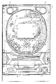
図1〜図3に示すように、パチンコ遊技機1は、額縁状に形成されたガラス扉枠2を有する。ガラス扉枠2の下部表面には、払出装置97から払い出された遊技球を貯留可能な打球供給皿(上皿)3がある。打球供給皿3の下部には、打球供給皿3に収容しきれない遊技球を貯留する余剰球受皿(下皿)4と遊技球を発射する打球操作ハンドル(操作ノブ)5が設けられている。なお、打球供給皿(上皿)3と余剰球受皿(下皿)4とは一体型に構成されていてもよい。ガラス扉枠2の背面には、図3に示すように、遊技枠11の一部を構成するプラ枠がある。プラ枠は、機構板を含み、機構板に電源回路(図示せず)やスピーカ27などの部品が取り付けられている。また、遊技枠11のプラ枠には、遊技枠11と遊技盤6との間の配線を中継する中継基板607が設けられている。また、遊技枠11の前面枠には、図3に示すように、遊技盤6が着脱可能に取り付けられている。なお、遊技盤6は、それを構成する板状体と、その板状体に取り付けられた種々の部品とを含む構造体である。また、遊技盤6の前面には遊技領域7が形成されている。   As shown in FIGS. 1 to 3, the pachinko gaming machine 1 has a glass door frame 2 formed in a frame shape. On the lower surface of the glass door frame 2, there is a hitting ball supply tray (upper plate) 3 capable of storing game balls paid out from the payout device 97. Under the hitting ball supply tray 3, an extra ball receiving tray (lower plate) 4 for storing game balls that cannot be accommodated in the hit ball supply tray 3 and a hitting operation handle (operation knob) 5 for launching the game balls are provided. . In addition, the hitting ball supply tray (upper plate) 3 and the surplus ball receiving tray (lower plate) 4 may be integrated. On the back surface of the glass door frame 2, there is a plastic frame constituting a part of the game frame 11 as shown in FIG. 3. The plastic frame includes a mechanism plate, and components such as a power supply circuit (not shown) and a speaker 27 are attached to the mechanism plate. In addition, the plastic frame of the game frame 11 is provided with a relay board 607 that relays the wiring between the game frame 11 and the game board 6. Moreover, as shown in FIG. 3, the game board 6 is attached to the front frame of the game frame 11 so that attachment or detachment is possible. The game board 6 is a structure including a plate-like body constituting the game board 6 and various components attached to the plate-like body. A game area 7 is formed on the front surface of the game board 6.

遊技領域7の中央付近には、それぞれが演出用の飾り図柄を可変表示する複数の可変表示部を含む可変表示装置(画像表示装置)9が設けられている。可変表示装置9には、例えば「左」、「中」、「右」の3つの可変表示部(図柄表示エリア)がある。可変表示装置9は、特別図柄表示器8による特別図柄の可変表示期間中に、装飾用(演出用)の図柄としての飾り図柄の可変表示を行う。飾り図柄の可変表示を行う可変表示装置9は、演出制御基板に搭載されている演出制御用マイクロコンピュータによって制御される。   Near the center of the game area 7, there is provided a variable display device (image display device) 9 including a plurality of variable display portions each variably displaying a decorative pattern for performance. The variable display device 9 has, for example, three variable display portions (symbol display areas) of “left”, “middle”, and “right”. The variable display device 9 performs variable display of a decorative symbol as a symbol for decoration (production) during the variable symbol display period of the special symbol by the special symbol indicator 8. The variable display device 9 that performs variable display of decorative symbols is controlled by an effect control microcomputer mounted on the effect control board.

可変表示装置9の下方には、識別情報としての特別図柄を可変表示する特別図柄表示器(特別図柄表示装置)8が設けられている。この実施の形態では、特別図柄表示器8は、例えば00〜99の数字を可変表示可能な簡易で小型の表示器(例えば7セグメントLED)で実現されている。なお、特別図柄表示器8は、2桁の数字を表示するものに限らず、0〜9など他の桁数の数字を可変表示するように構成されていてもよい。また、可変表示装置9は、特別図柄表示器8による特別図柄の可変表示期間中に、装飾用(演出用)の図柄としての飾り図柄の可変表示を行う。   Below the variable display device 9, there is provided a special symbol display (special symbol display device) 8 for variably displaying a special symbol as identification information. In this embodiment, the special symbol display 8 is realized by a simple and small display (for example, 7 segment LED) capable of variably displaying a number of, for example, 00 to 99. Note that the special symbol display 8 is not limited to displaying a two-digit number, and may be configured to variably display a number of other digits such as 0 to 9. In addition, the variable display device 9 performs variable display of a decorative symbol as a symbol for decoration (for production) during the variable symbol display period of the special symbol by the special symbol indicator 8.

なお、この実施の形態において、遊技機1は、特別図柄表示器8および可変表示装置9において識別情報の可変表示の表示結果が特定表示結果(大当り図柄(小当り図柄を含む))となった場合に遊技者にとって有利な特定遊技状態(大当り遊技状態(具体的には、確変大当り状態、通常大当り状態、突然確変大当り状態、小当り状態)に制御可能になるように構成されている。特定遊技状態とは、所定の遊技価値が付与された遊技者にとって有利な状態を意味する。具体的には、特定遊技状態(大当り遊技状態(小当り状態を含む))に移行されると、大入賞口の状態を打球が入賞しやすい遊技者にとって有利な状態となる。なお、後述するように、遊技制御用マイクロコンピュータ560は、特別図柄プロセス処理において特別図柄プロセスフラグの値にもとづいて遊技状態を制御する。この実施の形態では、後述するように、特別図柄プロセスフラグの値が5以上である場合に、遊技状態が特別遊技状態に移行された状態となる。   In this embodiment, in the gaming machine 1, the display result of the variable display of the identification information in the special symbol display 8 and the variable display device 9 is the specific display result (the big hit symbol (including the small hit symbol)). In this case, it is configured to be controllable to a specific gaming state advantageous to the player (a big hit gaming state (specifically, a probable big hit state, a normal big hit state, a sudden probable big hit state, a small hit state). A gaming state means a state that is advantageous to a player who is given a predetermined gaming value, specifically, when a transition is made to a specific gaming state (a big hit gaming state (including a small hit state)). The winning slot is advantageous for a player who is easy to win a ball, and the game control microcomputer 560, as will be described later, has a special symbol process in the special symbol process. In this embodiment, as will be described later, when the value of the special symbol process flag is 5 or more, the gaming state is shifted to the special gaming state. .

特別図柄表示器8の右側には、始動入賞口13,14に入った有効入賞球数すなわち保留記憶(始動記憶または始動入賞記憶ともいう。)数を表示する4つの表示器からなる特別図柄保留記憶表示器18が設けられている。有効始動入賞がある毎に、1つの表示器の表示色を変化させる。そして、特別図柄表示器8の可変表示が開始される毎に、1つの表示器の表示色をもとに戻す。なお、可変表示装置9の表示領域内に、保留記憶数を表示する4つの表示領域からなる特別図柄保留記憶表示領域を設けるようにしてもよい。また、この実施の形態では、保留記憶数の上限値を4とするが、上限値をより大きい値にしてもよい。さらに、上限値を、遊技状態に応じて変更可能であるようにしてもよい。   On the right side of the special symbol display 8 is a special symbol hold composed of four indicators for displaying the number of effective winning balls that have entered the start winning openings 13, 14, that is, the number of hold memories (also referred to as start memory or start prize memory). A storage indicator 18 is provided. Every time there is an effective start prize, the display color of one display is changed. Each time the variable display on the special symbol display 8 is started, the display color of one display is restored. In the display area of the variable display device 9, a special symbol reserved storage display area including four display areas for displaying the number of reserved memories may be provided. Further, in this embodiment, the upper limit value of the number of reserved memories is 4, but the upper limit value may be a larger value. Further, the upper limit value may be changed according to the gaming state.

可変表示装置9の下方には、第1始動入賞口13が設けられている。第1始動入賞口13に入賞した遊技球は、遊技盤6の背面に導かれ、第1始動口スイッチ13aによって検出される。   A first start winning opening 13 is provided below the variable display device 9. The game ball won in the first start winning opening 13 is guided to the back of the game board 6 and detected by the first start opening switch 13a.

また、第1始動入賞口13の真下には、第2始動入賞口14が形成されている。そして、第2始動入賞口14には開閉動作を行う可変入賞球装置15が設けられている。可変入賞球装置15が閉状態のときは第2始動入賞口14に遊技球が入賞せず、可変入賞球装置15が開状態のときに第2始動入賞口14に遊技球が入賞可能となる。可変入賞球装置15は、ソレノイド16によって開閉される。可変入賞球装置15が開状態になることによって、遊技球が第2始動入賞口14に入賞し易くなり(始動入賞し易くなり)、遊技者にとって有利な状態になる。第2始動入賞口14に入賞した遊技球は、遊技盤6の背面に導かれ、第2始動口スイッチ14aによって検出される。   Further, a second start winning opening 14 is formed immediately below the first starting winning opening 13. The second start winning opening 14 is provided with a variable winning ball apparatus 15 that opens and closes. When the variable winning ball device 15 is in the closed state, no gaming ball is won in the second starting winning port 14, and when the variable winning ball device 15 is in the open state, the gaming ball can be won in the second starting winning port 14. . The variable winning ball device 15 is opened and closed by a solenoid 16. When the variable winning ball device 15 is in the open state, it becomes easier for the game ball to win the second start winning opening 14 (easy to start winning), which is advantageous to the player. The game ball that has won the second start winning opening 14 is guided to the back of the game board 6 and detected by the second start opening switch 14a.

第2始動入賞口14の下方には、大当り遊技状態または小当り遊技状態においてソレノイド21によって開状態とされる特別可変入賞装置が設けられている。特別可変入賞装置は、開閉板20を備え、大入賞口を形成する。大入賞口に入った遊技球はカウントスイッチ23で検出される。   Below the second start winning opening 14, there is provided a special variable winning device that is opened by the solenoid 21 in the big hit gaming state or the small hit gaming state. The special variable winning device includes an opening / closing plate 20 and forms a big winning opening. The game ball that has entered the big prize opening is detected by the count switch 23.

可変表示装置9の右側には、遊技演出に用いられる可動部材としてのトロッコ151が設けられている。トロッコ151は、遊技演出において、演出制御手段の制御に従って、図6に示すように、可変表示装置9の右側から左側方向に飛び出すような演出を行うことができる。   On the right side of the variable display device 9, a trolley 151 as a movable member used for a game effect is provided. In the game effect, the truck 151 can produce an effect of jumping from the right side of the variable display device 9 to the left side as shown in FIG. 6 according to the control of the effect control means.

また、可変表示装置9の上部および右側には、遊技演出に用いられる可動部材としての梁152が設けられている。梁152は、遊技演出において、演出制御手段の制御に従って、図7に示すように、可変表示装置9の上部および右側から崩れ落ちるような演出を行うことができる。   Further, on the upper and right sides of the variable display device 9, a beam 152 is provided as a movable member used for a game effect. As shown in FIG. 7, the beam 152 can perform an effect that collapses from the upper part and the right side of the variable display device 9 according to the control of the effect control means in the game effect.

また、パチンコ遊技機1は、図4に示すように、遊技の進行中に遊技者が操作可能な操作ボタン81a〜81eを打球供給皿(上皿)3に備えている。例えば、操作ボタン81a〜81eが操作(押下)されると、可動部材としてのトロッコ151や梁152が動作する。   Further, as shown in FIG. 4, the pachinko gaming machine 1 includes operation buttons 81 a to 81 e that can be operated by the player during the game on the hitting ball supply tray (upper plate) 3. For example, when the operation buttons 81a to 81e are operated (pressed), the trolley 151 and the beam 152 as movable members are operated.

ゲート32に遊技球が入賞しゲートスイッチ32aで検出されると、普通図柄表示器10の表示の可変表示が開始される。この実施の形態では、左右のランプ(点灯時に図柄が視認可能になる)が交互に点灯することによって可変表示が行われ、例えば、可変表示の終了時に右側のランプが点灯すれば当りになる。そして、普通図柄表示器10における停止図柄が所定の図柄(当り図柄)である場合に、可変入賞球装置15が所定回数、所定時間だけ開放状態になる。普通図柄表示器10の下部には、ゲート32に入った入賞球数を表示する4つのLEDによる表示部を有する普通図柄始動記憶表示器41が設けられている。ゲート32への入賞がある毎に、普通図柄始動記憶表示器41は点灯するLEDを1増やす。そして、普通図柄表示器10の可変表示が開始される毎に、点灯するLEDを1減らす。   When a game ball wins the gate 32 and is detected by the gate switch 32a, the variable display of the normal symbol display 10 is started. In this embodiment, variable display is performed by alternately lighting left and right lamps (designs can be visually recognized when lit). For example, if the right lamp is lit at the end of variable display, it is a win. And when the stop symbol in the normal symbol display 10 is a predetermined symbol (winning symbol), the variable winning ball apparatus 15 is opened for a predetermined number of times. Below the normal symbol display 10 is provided a normal symbol start memory display 41 having a display unit with four LEDs for displaying the number of winning balls that have entered the gate 32. Each time there is a prize at the gate 32, the normal symbol start memory display 41 increases the number of LEDs to be turned on by one. Each time variable display on the normal symbol display 10 is started, the number of LEDs to be lit is reduced by one.

遊技盤6には、複数の入賞口(普通入賞口)29,30,33,39が設けられ、遊技球の入賞口29,30,33,39への入賞は、それぞれ入賞口スイッチ29a,30a,33a,39aによって検出される。各入賞口29,30,33,39は、遊技媒体を受け入れて入賞を許容する領域として遊技盤6に設けられる入賞領域を構成している。なお、始動入賞口13,14や大入賞口も、遊技媒体を受け入れて入賞を許容する入賞領域を構成する。また、それぞれの入賞口29,30,33,39に入賞した遊技球を1つのスイッチで検出するようにしてもよい。   The game board 6 is provided with a plurality of winning ports (ordinary winning ports) 29, 30, 33, and 39. The winning holes 29, 30, 33, and 39 for the game balls are awarded to the winning port switches 29a and 30a, respectively. , 33a, 39a. Each winning opening 29, 30, 33, 39 constitutes a winning area provided in the game board 6 as an area for accepting game media and allowing winning. The start winning openings 13, 14 and the big winning opening also constitute a winning area that accepts game media and allows winning. In addition, the game balls won in the respective winning openings 29, 30, 33, 39 may be detected by one switch.

遊技領域7の中央部には、可変表示装置9を囲むように飾り部材154が取り付けられており、飾り部材154の上部には、遊技中に点灯表示したり点滅表示される装飾ランプ(センター飾り用ランプ)が設けられている。なお、この実施の形態では、センター飾り用ランプとして6個のLED125a〜125fが設けられている。また、飾り部材154には、可変表示装置9を囲むように、遊技中に点灯表示したり点滅表示される装飾ランプ(ステージランプ)が設けられている。なお、この実施の形態では、ステージランプとして6個のLED126a〜126fが設けられている。   A decoration member 154 is attached to the center of the game area 7 so as to surround the variable display device 9, and a decoration lamp (center decoration) that is lit or flashed during the game is placed above the decoration member 154. Lamp). In this embodiment, six LEDs 125a to 125f are provided as center decoration lamps. In addition, the decoration member 154 is provided with a decoration lamp (stage lamp) that is lit or flashed during the game so as to surround the variable display device 9. In this embodiment, six LEDs 126a to 126f are provided as stage lamps.

また、遊技領域7の下部には、入賞しなかった遊技球を吸収するアウト口26がある。また、遊技領域7の外側の左右上部には、効果音を発する2つのスピーカ27が設けられている。遊技領域7の外周には、天枠ランプ、左枠ランプおよび右枠ランプが設けられている。さらに、遊技領域7における各構造物の周囲には装飾LEDが設置されている。天枠ランプ、左枠ランプ、右枠ランプおよび装飾用LEDは、遊技機に設けられている装飾発光体の一例である。この実施の形態では、天枠ランプとして12個のLED281a〜281lが設けられている。また、左枠ランプとして6個のLED282a〜282fが設けられている。また、右枠ランプとして6個のLED283a〜283fが設けられている。   Further, at the lower part of the game area 7, there is an out port 26 for absorbing game balls that have not won a prize. Two speakers 27 that emit sound effects are provided on the left and right upper portions outside the game area 7. A top frame lamp, a left frame lamp, and a right frame lamp are provided on the outer periphery of the game area 7. Further, a decoration LED is installed around each structure in the game area 7. The top frame lamp, the left frame lamp, the right frame lamp, and the decoration LED are examples of a decorative light emitter provided in the gaming machine. In this embodiment, twelve LEDs 281a to 281l are provided as ceiling lamps. In addition, six LEDs 282a to 282f are provided as left frame lamps. In addition, six LEDs 283a to 283f are provided as right frame lamps.

また、図4に示すように、打球供給皿(上皿)3に、上皿ランプとして6個のLED82a〜82fが設けられている。この実施の形態では、図4に示すように、打球供給皿(上皿)3の左側面に2個のLED82a,82bが、正面に2個のLED82c,82dが、右側面に2個のLED82e,82fが設けられている。なお、この実施の形態において、遊技機の正面とは、遊技者が遊技をしているときに遊技者と対向する側(遊技者が見ている側)の面をいう。また、遊技機の側面とは、遊技者が遊技をしているときに遊技者の視線方向と直交する側の面をいう。この場合に、遊技者から見て左側の側面を左側面といい、遊技者から見て右側の側面を右側面という。これらのLED82a〜82fは、それぞれ打球供給皿(上皿)3の背面に設けられた各基板331,332,333,334に搭載されている。   Further, as shown in FIG. 4, the hitting ball supply tray (upper plate) 3 is provided with six LEDs 82 a to 82 f as upper plate lamps. In this embodiment, as shown in FIG. 4, two LEDs 82a and 82b are provided on the left side of the hitting ball supply tray (upper plate) 3, two LEDs 82c and 82d are provided on the front, and two LEDs 82e are provided on the right side. , 82f are provided. In this embodiment, the front of the gaming machine refers to the surface on the side facing the player when the player is playing (the side on which the player is viewing). Further, the side surface of the gaming machine refers to a surface on the side orthogonal to the player's line-of-sight direction when the player is playing a game. In this case, the left side as viewed from the player is referred to as the left side, and the right side as viewed from the player is referred to as the right side. These LEDs 82 a to 82 f are mounted on the respective substrates 331, 332, 333 and 334 provided on the back surface of the hitting ball supply tray (upper plate) 3.

また、打球供給皿(上皿)3の左側面には、図4に示すように、逆「く」の字形状のレンズカバー821が取り付けられており、LED82a,82bが点灯または点滅すると、レンズカバー821で光が拡散されてレンズカバー821全体が光って見える。具体的には、レンズカバー821は、保護用のレンズカバーと、ローレット状やクロスカット状に形成され裏面がギザギザ形状に形成された光拡散用のレンズカバーとで構成されており、LED82a,82bが点灯または点滅すると、光拡散用のレンズカバーで光が拡散されてレンズカバー821全体が光って見えるようにすることができる。また、光拡散用のレンズカバーには、所定色(例えば青)が着色されており、LED82a,82bが点灯または点滅することより、レンズカバー821全体が所定色(例えば青)に光って見える。なお、レンズカバー821として透明なものを用い、LED82a,82bとしてフルカラーLEDを用いて、LED82a,82bの発光色を変えることによって、レンズカバー821全体が所定色(例えば青)に光って見えるようにしてもよい。なお、打球供給皿(上皿)3の左側面のレンズカバー821の内側の三角形状の部分821Aにもレンズ部品(例えば、ロゴマークなどが描かれたもの)を用いて、内側のLED82a,82b(LED82a,82bとは別のLEDを設けてもよい)によって発光して見えるようにしてもよい。また、打球供給皿(上皿)3の左側面のレンズカバー821の内側の三角形状の部分821Aとして単に不透明な合成樹脂製の部品を用いてもよい。   Further, as shown in FIG. 4, a lens cover 821 having an inverted “<” shape is attached to the left side surface of the hitting ball supply tray (upper plate) 3, and when the LEDs 82a and 82b are turned on or blinking, the lens Light is diffused by the cover 821, and the entire lens cover 821 appears to shine. Specifically, the lens cover 821 includes a protective lens cover and a light diffusion lens cover that is formed in a knurled shape or a cross-cut shape and has a jagged back surface, and the LEDs 82a and 82b. When is turned on or blinks, the light is diffused by the light diffusing lens cover so that the entire lens cover 821 can be seen to shine. The lens cover for light diffusion is colored in a predetermined color (for example, blue), and the entire LED cover 821 appears to shine in the predetermined color (for example, blue) by turning on or blinking the LEDs 82a and 82b. In addition, by using a transparent lens cover 821 and using full color LEDs as the LEDs 82a and 82b and changing the emission color of the LEDs 82a and 82b, the entire lens cover 821 can be seen to shine in a predetermined color (for example, blue). May be. It should be noted that lens parts (for example, those on which logo marks or the like are drawn) are also used for the inner triangular portion 821A of the lens cover 821 on the left side surface of the hitting ball supply tray (upper plate) 3, and the inner LEDs 82a and 82b are used. You may make it light-emit and see by (You may provide LED different from LED82a, 82b.). Alternatively, an opaque synthetic resin part may be used as the triangular portion 821A inside the lens cover 821 on the left side surface of the hitting ball supply tray (upper plate) 3.

また、打球供給皿(上皿)3の正面には、図4に示すように、帯型形状のレンズカバー822が取り付けられており、LED82c,82dが点灯または点滅すると、レンズカバー822で光が拡散されてレンズカバー822全体が光って見える。具体的には、レンズカバー822は、保護用のレンズカバーと、ローレット状やクロスカット状に形成され裏面がギザギザ形状に形成された光拡散用のレンズカバーとで構成されており、LED82c,82dが点灯または点滅すると、光拡散用のレンズカバーで光が拡散されてレンズカバー822全体が光って見えるようにすることができる。また、光拡散用のレンズカバーには、所定色(例えば青)が着色されており、LED82c,82dが点灯または点滅することより、レンズカバー822全体が所定色(例えば青)に光って見える。なお、レンズカバー822として透明なもの(無色の透明性のある部材)を用い、LED82c,82dとしてフルカラーLEDを用いて、LED82c,82dの発光色を変えることによって、レンズカバー822全体が所定色(例えば青)に光って見えるようにしてもよい。   Further, as shown in FIG. 4, a belt-shaped lens cover 822 is attached to the front of the hitting ball supply tray (upper plate) 3, and when the LEDs 82 c and 82 d are turned on or blinking, the lens cover 822 emits light. When diffused, the entire lens cover 822 appears to shine. Specifically, the lens cover 822 includes a protective lens cover and a light diffusion lens cover that is formed in a knurled shape or a cross-cut shape and has a jagged back surface, and the LEDs 82c and 82d. When is turned on or blinks, the light is diffused by the light diffusing lens cover, and the entire lens cover 822 can be seen to shine. The lens cover for light diffusion is colored with a predetermined color (for example, blue), and the LEDs 82c and 82d are turned on or blinking, so that the entire lens cover 822 appears to shine in the predetermined color (for example, blue). The lens cover 822 is made of a transparent material (colorless and transparent member), the full-color LED is used as the LEDs 82c and 82d, and the emission color of the LEDs 82c and 82d is changed. For example, it may appear to shine blue).

また、打球供給皿(上皿)3の右側面には、図4に示すように、「く」の字形状のレンズカバー823が取り付けられており、LED82e,82fが点灯または点滅すると、レンズカバー823で光が拡散されてレンズカバー823全体が光って見える。具体的には、レンズカバー823は、保護用のレンズカバーと、ローレット状やクロスカット状に形成され裏面がギザギザ形状に形成された光拡散用のレンズカバーとで構成されており、LED82e,82fが点灯または点滅すると、光拡散用のレンズカバーで光が拡散されてレンズカバー823全体が光って見えるようにすることができる。また、光拡散用のレンズカバーには、所定色(例えば青)が着色されており、LED82e,82fが点灯または点滅することより、レンズカバー823全体が所定色(例えば青)に光って見える。なお、レンズカバー823として透明なものを用い、LED82e,82fとしてフルカラーLEDを用いて、LED82e,82fの発光色を変えることによって、レンズカバー823全体が所定色(例えば青)に光って見えるようにしてもよい。なお、打球供給皿(上皿)3の右側面のレンズカバー823の内側の三角形状の部分823Aにもレンズ部品(例えば、ロゴマークなどが描かれたもの)を用いて、内側のLED82e,82f(LED82e,82fとは別のLEDを設けてもよい)によって発光して見えるようにしてもよい。また、打球供給皿(上皿)3の右側面のレンズカバー823の内側の三角形状の部分823Aとして単に不透明な合成樹脂製の部品を用いてもよい。   Further, as shown in FIG. 4, a “<”-shaped lens cover 823 is attached to the right side surface of the hitting ball supply tray (top plate) 3, and when the LEDs 82 e and 82 f are lit or blinking, the lens cover At 823, the light is diffused and the entire lens cover 823 appears to shine. Specifically, the lens cover 823 includes a protective lens cover and a light diffusion lens cover formed in a knurled shape or a cross-cut shape and having a jagged back surface, and the LEDs 82e and 82f. When is turned on or blinks, the light is diffused by the light diffusing lens cover, and the entire lens cover 823 can be seen to shine. Further, the lens cover for light diffusion is colored in a predetermined color (for example, blue), and the LEDs 82e and 82f are turned on or blinking, so that the entire lens cover 823 appears to shine in the predetermined color (for example, blue). In addition, by using a transparent lens cover 823 and using full-color LEDs as the LEDs 82e and 82f and changing the emission color of the LEDs 82e and 82f, the entire lens cover 823 can be seen to shine in a predetermined color (for example, blue). May be. It should be noted that the inner LED 82e, 82f is also used by using lens parts (for example, a logo mark or the like) also on the triangular portion 823A inside the lens cover 823 on the right side surface of the hitting ball supply tray (top plate) 3. You may make it light-emit by (you may provide LED different from LED82e, 82f). Alternatively, an opaque synthetic resin component may be used as the triangular portion 823A inside the lens cover 823 on the right side surface of the hitting ball supply tray (upper plate) 3.

なお、打球供給皿(上皿)3の各レンズカバーのうちの2つのレンズカバー821,823および上皿ランプの各LEDのうちの4つのLED82a,82b,82e,82fは、それぞれ打球供給皿(上皿)3の左側面および右側面に、遊技中の遊技者からは視認しずらい位置に設けられている。また、図4に示すように、操作ボタン81a〜81eに操作ボタンランプとして1個のLED83が設けられている。   The two lens covers 821 and 823 of the lens covers of the hitting ball supply tray (upper plate) 3 and the four LEDs 82a, 82b, 82e, and 82f of the LEDs of the upper tray lamp are respectively a hitting ball supply tray ( On the left side and the right side of the upper plate 3), it is provided at a position that is difficult for a player who is playing the game to view. As shown in FIG. 4, the operation buttons 81a to 81e are provided with one LED 83 as an operation button lamp.

また、図5に示すように、余剰球受皿(下皿)4に、下皿ランプとして、6個のLED84a〜84fが設けられている。この実施の形態では、図5に示すように、余剰球受皿(下皿)4の周縁部(本例では、余剰球受皿(下皿)4の上面)に6個のLED84a〜84fが設けられている。なお、これらのLED84a〜84fは、余剰球受皿(下皿)4の背面に設けられた基板431に搭載されている。   Moreover, as shown in FIG. 5, six LEDs 84a-84f are provided in the surplus sphere receptacle (lower pan) 4 as a lower pan lamp. In this embodiment, as shown in FIG. 5, six LEDs 84 a to 84 f are provided on the peripheral portion of the surplus ball tray (lower pan) 4 (in this example, the upper surface of the surplus ball tray (lower pan) 4). ing. These LEDs 84 a to 84 f are mounted on a substrate 431 provided on the back surface of the surplus sphere tray (lower pan) 4.

また、余剰球受皿(下皿)4の上面には、図5に示すように、「コ」の字形状のレンズカバー841が取り付けられており、LED84a〜84fが点灯または点滅すると、レンズカバー841で光が拡散されてレンズカバー841全体が光って見える。具体的には、レンズカバー841は、保護用のレンズカバーt9、ローレット状やクロスカット状に形成され裏面がギザギザ形状に形成された光拡散用のレンズカバーとで構成されており、LED84a〜84fが点灯または点滅すると、光拡散用のレンズカバーで光が拡散されてレンズカバー841全体が光って見えるようにすることができる。また、光拡散用のレンズカバーには、所定色(例えば青)が着色されており、LED84a〜84fが点灯または点滅することより、レンズカバー841全体が所定色(例えば青)に光って見える。なお、レンズカバー841として透明なものを用い、LED84a〜84fとしてフルカラーLEDを用いて、LED84a〜84fの発光色を変えることによって、レンズカバー841全体が所定色(例えば青)に光って見えるようにしてもよい。   Further, as shown in FIG. 5, a “U” -shaped lens cover 841 is attached to the upper surface of the surplus sphere tray (lower plate) 4, and when the LEDs 84 a to 84 f are lit or blinking, the lens cover 841 is mounted. The light is diffused and the entire lens cover 841 appears to shine. Specifically, the lens cover 841 includes a protective lens cover t9, a light diffusion lens cover formed in a knurled shape or a cross-cut shape, and a back surface formed in a jagged shape, and the LEDs 84a to 84f. When is turned on or blinks, the light is diffused by the light diffusing lens cover so that the entire lens cover 841 can be seen to shine. The lens cover for light diffusion is colored with a predetermined color (for example, blue), and the LEDs 84a to 84f are turned on or blinking, so that the entire lens cover 841 appears to shine in the predetermined color (for example, blue). In addition, by using a transparent lens cover 841 and using full color LEDs as the LEDs 84a to 84f and changing the emission color of the LEDs 84a to 84f, the entire lens cover 841 can be seen to shine in a predetermined color (for example, blue). May be.

なお、この実施の形態では、通常の遊技演出に応じた上皿ランプや下皿ランプを含む各ランプのLEDの制御として、変動パターンに応じた点灯または点滅の制御が行われる。この実施の形態では、後述するように、変動パターンに応じたプロセスデータにもとづいて各ランプのLEDの点灯または点滅の制御が行われる。   In this embodiment, lighting or blinking control according to the variation pattern is performed as the LED control of each lamp including the upper pan lamp and the lower pan lamp according to the normal game effect. In this embodiment, as will be described later, the lighting or blinking control of the LED of each lamp is performed based on the process data corresponding to the variation pattern.

また、打球供給皿(上皿)3は、図4に示すように、ヒンジ部312を介して回動可能に遊技枠11に取り付けられている。また、ヒンジ部312がある側とは反対側の右側面には、打球供給皿(上皿)3を開放するための開放レバー317が設けられており、開放レバー317を押下することによって、遊技枠との係合状態が解除され、ヒンジ部312を軸に打球供給皿(上皿)3が回動可能な状態とされる。また、打球供給皿(上皿)3には、遊技球を貯留するための皿部350が設けられており、払出処理や球貸し処理が行われると、遊技球の注入口311から遊技球が注入され、皿部350に遊技球が貯留される。また、皿部350は左側面から右側面に向かう方向に低くなるように傾斜が設けられており、皿部350に貯留された遊技球は左側面から右側面の方向に誘導され、通路350Aを通って打球位置に誘導される。また、打球供給皿(上皿)3には上皿スライドレバー313が設けられている。打球供給皿(上皿)3の底部には打球供給皿(上皿)3に溜まった遊技球を余剰球受皿(下皿)4に移すための貫通口が設けられており、上皿スライドレバー313をスライドさせることによって打球供給皿(上皿)3の底部の貫通口が開いた状態となり、打球供給皿(上皿)3に溜まっている遊技球を余剰球受皿(下皿)4側に流入させることができる。また、打球供給皿(上皿)3には、球貸し要求操作を行うための球貸しスイッチ314や、カードユニットに挿入されたプリペイドカード等の返却操作を行うための返却スイッチ315が設けられている。なお、プリペイドカードの返却操作を行う場合に限らず、例えば、コイン形の記録媒体(例えば、ICコイン)をカードユニットに投入することにより球貸し処理を行う遊技機である場合には、返却スイッチ315を操作することによってコインが返却されるようにしてもよい。また、打球供給皿(上皿)3には、プリペイドカード等の残り度数(球貸し可能な度数、すなわち記録媒体に記録されている価値の量)を表示するための度数表示LED316が設けられている。   Further, as shown in FIG. 4, the hitting ball supply tray (upper tray) 3 is attached to the game frame 11 via a hinge portion 312 so as to be rotatable. Further, an opening lever 317 for opening the hitting ball supply tray (upper plate) 3 is provided on the right side surface opposite to the side where the hinge portion 312 is provided. The engagement state with the frame is released, and the hitting ball supply tray (upper plate) 3 is rotatable about the hinge portion 312. Further, the hitting ball supply tray (upper plate) 3 is provided with a tray portion 350 for storing game balls, and when a payout process or a ball lending process is performed, the game balls are received from the game ball inlet 311. The game ball is stored in the dish portion 350. Further, the dish part 350 is inclined so as to become lower in the direction from the left side surface to the right side surface, and the game balls stored in the dish part 350 are guided from the left side surface to the right side surface, and pass through the passage 350A. It is guided to the hitting position through. Further, an upper plate slide lever 313 is provided on the hitting ball supply plate (upper plate) 3. The bottom of the hitting ball supply tray (upper plate) 3 is provided with a through-hole for transferring the game balls accumulated in the hitting ball supply tray (upper plate) 3 to the surplus ball receiving tray (lower plate) 4. By sliding 313, the through hole at the bottom of the hit ball supply tray (upper plate) 3 is opened, and the game balls accumulated in the hit ball supply tray (upper plate) 3 are moved to the surplus ball receiving tray (lower plate) 4 side. Can flow in. The hitting ball supply tray (top plate) 3 is provided with a ball lending switch 314 for performing a lending request operation and a return switch 315 for returning a prepaid card inserted into the card unit. Yes. Note that the return switch is not limited to a prepaid card return operation. For example, if the game machine performs a ball lending process by inserting a coin-shaped recording medium (for example, an IC coin) into a card unit, a return switch The coin may be returned by operating 315. Further, the hitting ball supply tray (top plate) 3 is provided with a frequency display LED 316 for displaying the remaining frequency of the prepaid card or the like (the frequency that can be lent out, that is, the amount of value recorded on the recording medium). Yes.

また、余剰球受皿(下皿)4は、図5に示すように、ヒンジ部401を介して回動可能に遊技枠11に取り付けられている。また、余剰球受皿(下皿)4には、遊技球を貯留するための皿部450が設けられており、上皿スライドレバー313が操作されたときに打球供給皿(上皿)3から流入した遊技球や、打球供給皿(上皿)3が満タン状態となってあふれて流入した遊技球が貯留される。この場合、上皿スライドレバー313が操作されたり、打球供給皿(上皿)3が満タン状態となると、打球供給皿(上皿)3からの遊技球は注入口403を通って注入され皿部450に貯留される。また、余剰球受皿(下皿)4には下皿スライドレバー402が設けられている。余剰球受皿(下皿)4の底部には余剰球受皿(下皿)4に溜まった遊技球を玉箱(遊技球を入れるための箱)に移すための貫通口が設けられており、下皿スライドレバー402をスライドさせることによって余剰球受皿(下皿)4の底部の貫通口が開いた状態となり、余剰球受皿(下皿)4に溜まっている遊技球を玉箱に流入させることができる。   Further, as shown in FIG. 5, the surplus ball tray (lower pan) 4 is attached to the game frame 11 so as to be rotatable via a hinge portion 401. The surplus ball receiving tray (lower tray) 4 is provided with a tray portion 450 for storing game balls. When the upper tray slide lever 313 is operated, it flows from the hitting ball supply tray (upper tray) 3. The game balls and the game balls that have overflowed and flowed in when the hit ball supply tray (upper plate) 3 is full are stored. In this case, when the upper plate slide lever 313 is operated, or when the hitting ball supply tray (upper plate) 3 becomes full, the game balls from the hitting ball supply plate (upper plate) 3 are injected through the inlet 403 and the Stored in the portion 450. The surplus ball receiving tray (lower tray) 4 is provided with a lower tray slide lever 402. At the bottom of the extra ball tray (lower plate) 4, a through-hole is provided for transferring the game balls accumulated in the extra ball tray (lower plate) 4 to a ball box (box for containing game balls). By sliding the plate slide lever 402, the through-hole at the bottom of the surplus ball receiving tray (lower tray) 4 is opened, and the game balls accumulated in the surplus ball receiving tray (lower tray) 4 can flow into the ball box. it can.

打球発射装置から発射された遊技球は、打球レールを通って遊技領域7に入り、その後、遊技領域7を下りてくる。遊技球が第1始動入賞口13に入り第1始動口スイッチ13aで検出されると、または遊技球が第2始動入賞口14に入り第2始動入賞口スイッチ14aで検出されると、図柄の可変表示を開始できる状態であれば、特別図柄表示器8において特別図柄が可変表示(変動)を始めるとともに、可変表示装置9において飾り図柄が可変表示(変動)を始める。図柄の可変表示を開始できる状態でなければ、始動入賞記憶数を1増やす。   The game balls launched from the hit ball launching device enter the game area 7 through the hit ball rail, and then descend the game area 7. When a game ball enters the first start winning opening 13 and is detected by the first start opening switch 13a, or when a game ball enters the second start winning opening 14 and is detected by the second start winning opening switch 14a, If the variable display can be started, the special symbol on the special symbol display unit 8 starts variable display (variation), and the variable display device 9 starts variable display (variation). If it is not in a state where the variable display of symbols can be started, the start winning memory number is increased by one.

特別図柄表示器8における特別図柄の可変表示、および可変表示装置9における飾り図柄の可変表示は、一定時間が経過したときに停止する。停止時の特別図柄(停止図柄)が大当り図柄(特定表示結果)であると、大当り遊技状態に移行する。すなわち、大入賞口が、一定時間経過するまで、または、所定個数(例えば10個)の遊技球が入賞するまで開放する。   The variable display of the special symbol on the special symbol display 8 and the variable display of the decorative symbol on the variable display device 9 are stopped when a certain time has passed. If the special symbol (stop symbol) at the time of stoppage is a jackpot symbol (specific display result), the game shifts to a jackpot gaming state. That is, the special winning opening is opened until a predetermined time elapses or a predetermined number (for example, 10) of game balls wins.

遊技球がゲート32に入賞すると、普通図柄表示器10において普通図柄が可変表示される状態になる。また、普通図柄表示器10における停止図柄が所定の図柄(当り図柄)である場合に、可変入賞球装置15が所定時間だけ開放状態になる。さらに、確変状態では、普通図柄表示器10における停止図柄が当り図柄になる確率が高められるとともに、可変入賞球装置15の開放時間と開放回数が高められる。また、時短状態(特別図柄の可変表示時間が短縮される遊技状態)において、可変入賞球装置15の開放時間と開放回数が高められるようにしてもよい。   When the game ball wins the gate 32, the normal symbol display unit 10 is in a state where the normal symbol is variably displayed. When the stop symbol on the normal symbol display 10 is a predetermined symbol (winning symbol), the variable winning ball device 15 is opened for a predetermined time. Further, in the probability variation state, the probability that the stop symbol in the normal symbol display 10 becomes a winning symbol is increased, and the opening time and the number of times of opening of the variable winning ball device 15 are increased. Further, in the short time state (the game state in which the variable symbol display time for special symbols is shortened), the opening time and the number of opening times of the variable winning ball device 15 may be increased.

上記のように、この実施の形態のパチンコ遊技機1には、発光体としてのランプやLEDが各所に設けられている。さらに、プリペイドカードが挿入されることによって球貸しを可能にするプリペイドカードユニット(以下、単に「カードユニット」ともいう。)が、パチンコ遊技機1に隣接して設置される(図示せず)。   As described above, the pachinko gaming machine 1 of this embodiment is provided with lamps and LEDs as light emitters in various places. Further, a prepaid card unit (hereinafter also simply referred to as a “card unit”) that enables ball lending by inserting a prepaid card is installed adjacent to the pachinko gaming machine 1 (not shown).

図8は、遊技枠11を開いた状態を示す説明図である。図8に示すように、遊技枠11側の裏面には、ICなどを搭載するための5つの基板(枠側IC基板)602,603,604,605A,605Bが取り付けられている。遊技枠11の上部に取り付けられた枠側IC基板602は、シリアルデータをパラレルデータに変換するシリアル−パラレル変換IC610,611が搭載されており、各シリアル−パラレル変換IC610,611から、天枠ランプの各LED281a〜281lに制御信号が供給される。また、遊技枠11の右側(裏面から見て左側)に取り付けられた枠側IC基板603は、シリアル−パラレル変換IC612が搭載されており、シリアル−パラレル変換IC612から、右枠ランプの各LED283a〜283fに制御信号が供給される。また、遊技枠11の左側(裏面から見て右側)に取り付けられた枠側IC基板604は、シリアル−パラレル変換IC613が搭載されており、シリアル−パラレル変換IC613から、左枠ランプの各LED282a〜282fに制御信号が供給される。   FIG. 8 is an explanatory diagram showing a state in which the game frame 11 is opened. As shown in FIG. 8, five substrates (frame side IC substrates) 602, 603, 604, 605A, and 605B for mounting ICs and the like are attached to the rear surface on the game frame 11 side. The frame-side IC board 602 attached to the upper part of the game frame 11 is mounted with serial-parallel conversion ICs 610 and 611 for converting serial data into parallel data. From the serial-parallel conversion ICs 610 and 611, the top frame lamp A control signal is supplied to each of the LEDs 281a to 281l. Further, the frame side IC substrate 603 attached to the right side (left side when viewed from the back side) of the game frame 11 is mounted with a serial-parallel conversion IC 612, and each LED 283 a to the right frame lamp from the serial-parallel conversion IC 612. A control signal is supplied to 283f. Further, the frame side IC substrate 604 attached to the left side (right side as viewed from the back side) of the game frame 11 is mounted with a serial-parallel conversion IC 613, and each LED 282 a-of the left frame lamp from the serial-parallel conversion IC 613. A control signal is supplied to 282f.

また、遊技枠11の下部であって打球供給皿(上皿)3の背面側の位置に取り付けられた枠側IC基板605Aは、シリアル−パラレル変換IC614、およびパラレルデータをシリアルデータに変換する入力IC620が搭載されており、シリアル−パラレル変換IC614から、操作ボタン81a〜81eに設けられた操作ボタンランプのLED83および打球供給皿(上皿)3に設けられた上皿ランプの各LED82a〜82fに制御信号が供給される。また、操作ボタン81a〜81eからの検出信号が入力IC620にパラレルに入力される。また、遊技枠11の下部であって余剰球受皿(下皿)4の背面側の位置に取り付けられた枠側IC基板605Bは、シリアル−パラレル変換IC615が搭載されており、シリアル−パラレル変換IC615から、余剰球受皿(下皿)4に設けられた下皿ランプの各LED84a〜84fに制御信号が供給される。   Further, a frame side IC board 605A attached to the lower side of the game frame 11 and on the back side of the hitting ball supply tray (upper plate) 3 has a serial-parallel conversion IC 614 and an input for converting parallel data into serial data. IC 620 is mounted, from serial-parallel conversion IC 614 to LED 83 a of the operation button lamp provided on operation buttons 81 a to 81 e and each LED 82 a to 82 f of the upper plate lamp provided on hitting ball supply tray (upper plate) 3. A control signal is supplied. In addition, detection signals from the operation buttons 81a to 81e are input to the input IC 620 in parallel. A frame-side IC board 605B attached to the lower side of the game frame 11 and on the back side of the surplus ball tray (lower plate) 4 is mounted with a serial-parallel conversion IC 615, and the serial-parallel conversion IC 615 is mounted. Then, control signals are supplied to the LEDs 84 a to 84 f of the lower pan lamps provided in the surplus ball tray (lower pan) 4.

なお、図8に示すように、この実施の形態では、各枠側IC基板602,603,604,605A,605Bうち遊技枠11の上部に取り付けられた枠側IC基板602は、2つのシリアル−パラレル変換ICを搭載した集合基板として構成されている。そのように構成することによって、シリアル−パラレル変換ICを搭載する基板を集約することができ、遊技機における部品点数を低減することができる。   As shown in FIG. 8, in this embodiment, the frame-side IC board 602 attached to the upper part of the game frame 11 among the frame-side IC boards 602, 603, 604, 605A, 605B has two serial- It is configured as a collective board on which a parallel conversion IC is mounted. With such a configuration, it is possible to consolidate boards on which serial-parallel conversion ICs are mounted, and it is possible to reduce the number of parts in the gaming machine.

また、図8に示すように、遊技枠11側には中継基板607が取り付けられており、中継基板607からの配線は、枠側IC基板604に接続され、枠側IC基板604から枠側IC基板602に接続され、さらに枠側IC基板602から枠側IC基板603に接続される。また、中継基板607からの配線は、枠側基板605Aに接続される。また、中継基板607からの配線は、枠側基板605Bに接続される。また、各枠側IC基板602〜604間の配線や、枠側IC基板604,605A,605Bと中継基板607との間の配線は、図8に示すように、各基板にコネクタ156a〜156jを用いて接続される。なお、図8では、基板に垂直方向に接続するタイプのコネクタを用いて配線接続を行う場合を示しているが、例えば、基板に対して水平方向に接続するタイプのコネクタを用いて配線接続を行うようにしてもよい。   Also, as shown in FIG. 8, a relay board 607 is attached to the game frame 11 side, and wiring from the relay board 607 is connected to the frame side IC board 604, and the frame side IC board 604 is connected to the frame side IC. The frame side IC substrate 602 is connected to the frame side IC substrate 603. Further, the wiring from the relay board 607 is connected to the frame side board 605A. Further, the wiring from the relay board 607 is connected to the frame side board 605B. Further, the wiring between the frame side IC substrates 602 to 604 and the wiring between the frame side IC substrates 604, 605A, and 605B and the relay substrate 607 are provided with connectors 156a to 156j on each substrate as shown in FIG. Connected. FIG. 8 shows a case where the wiring connection is performed using a connector of a type that is connected to the board in the vertical direction. You may make it perform.

図6に示すように、中継基板607のコネクタ156aからの配線は、枠側IC基板604のコネクタ156bに接続される。枠側IC基板604の配線パターンは、コネクタ156bからさらに分岐され、一方がシリアル−パラレル変換IC613に接続され、他の一方がコネクタ156cに接続されるようになっている。また、枠側IC基板604において、コネクタ156cは、枠側IC基板602側の端部に配置されている。枠側IC基板604のコネクタ156cからの配線は、枠側IC基板602のコネクタ156dに接続される。枠側IC基板602の配線パターンは、コネクタ156dからさらに3つに分岐され、シリアル−パラレル変換IC610、シリアル−パラレル変換IC611およびコネクタ156eに接続されるようになっている。また、枠側IC基板602において、コネクタ156eは、枠側IC基板603側の端部に配置されている。枠側IC基板602のコネクタ156eからの配線は、枠側IC基板603のコネクタ156fに接続される。枠側IC基板603の配線パターンは、シリアル−パラレル変換IC612に接続されるようになっている。   As shown in FIG. 6, the wiring from the connector 156 a of the relay board 607 is connected to the connector 156 b of the frame side IC board 604. The wiring pattern of the frame side IC substrate 604 is further branched from the connector 156b, one is connected to the serial-parallel conversion IC 613, and the other is connected to the connector 156c. Further, in the frame side IC substrate 604, the connector 156c is arranged at an end portion on the frame side IC substrate 602 side. The wiring from the connector 156c of the frame side IC substrate 604 is connected to the connector 156d of the frame side IC substrate 602. The wiring pattern of the frame side IC substrate 602 is further branched into three from the connector 156d and connected to the serial-parallel conversion IC 610, the serial-parallel conversion IC 611, and the connector 156e. Further, in the frame side IC substrate 602, the connector 156e is disposed at an end portion on the frame side IC substrate 603 side. The wiring from the connector 156e of the frame side IC substrate 602 is connected to the connector 156f of the frame side IC substrate 603. The wiring pattern of the frame side IC substrate 603 is connected to the serial-parallel conversion IC 612.

また、中継基板607のコネクタ156gからの配線は、枠側IC基板605Aのコネクタ156hに接続される。枠側IC基板605Aの配線パターンは、コネクタ156hからさらに分岐され、一方がシリアル−パラレル変換IC614に接続され、他の一方が入力IC620に接続されるようになっている。   Further, the wiring from the connector 156g of the relay board 607 is connected to the connector 156h of the frame side IC board 605A. The wiring pattern of the frame side IC substrate 605A is further branched from the connector 156h, and one is connected to the serial-parallel conversion IC 614 and the other is connected to the input IC 620.

また、中継基板607のコネクタ156iからの配線は、枠側IC基板605Bのコネクタ156jに接続される。枠側IC基板605Bの配線パターンは、シリアル−パラレル変換IC615に接続されるようになっている。   Further, the wiring from the connector 156i of the relay board 607 is connected to the connector 156j of the frame side IC board 605B. The wiring pattern of the frame side IC substrate 605B is connected to the serial-parallel conversion IC 615.

また、図8に示すように、遊技枠11の開放を検出するためのドア開放センサ155が取り付けられている。   Further, as shown in FIG. 8, a door opening sensor 155 for detecting the opening of the game frame 11 is attached.

図9は、遊技盤6の裏面を示す説明図である。図9に示すように、遊技盤6の裏面には、ICなどを搭載するための基盤(盤側IC基板)601が取り付けられている。盤側IC基板601には、シリアルデータをパラレルデータに変換する3つのシリアル−パラレル変換IC616〜618が搭載されており、シリアル−パラレル変換IC616から、各可動部材151,152を駆動するためのモータ151a,152aに制御信号が供給される。また、シリアル−パラレル変換IC617から、センター飾り用ランプの各LED125a〜125fに制御信号が供給される。また、シリアル−パラレル変換IC618から、ステージランプの各LED126a〜126fに制御信号が供給される。   FIG. 9 is an explanatory view showing the back surface of the game board 6. As shown in FIG. 9, a base (board-side IC substrate) 601 for mounting an IC or the like is attached to the back surface of the game board 6. The board side IC substrate 601 is equipped with three serial-parallel conversion ICs 616 to 618 for converting serial data into parallel data, and a motor for driving the movable members 151 and 152 from the serial-parallel conversion IC 616. A control signal is supplied to 151a and 152a. Further, a control signal is supplied from the serial-parallel conversion IC 617 to the LEDs 125a to 125f of the center decoration lamp. Further, a control signal is supplied from the serial-parallel conversion IC 618 to each LED 126a to 126f of the stage lamp.

なお、図9に示すように、この実施の形態では、盤側IC基板601は、3つのシリアル−パラレル変換ICを搭載した集合基板として構成されている。そのように構成することによって、シリアル−パラレル変換ICを搭載する基板を集約することができ、遊技機における部品点数を低減することができる。   As shown in FIG. 9, in this embodiment, the board side IC substrate 601 is configured as a collective substrate on which three serial-parallel conversion ICs are mounted. With such a configuration, it is possible to consolidate boards on which serial-parallel conversion ICs are mounted, and it is possible to reduce the number of parts in the gaming machine.

また、盤側IC基板601は、パラレルデータをシリアルデータに変換する入力IC621が搭載されており、各可動部材151,152の位置を検出するための位置センサ151b,152bからの検出信号が入力IC621にパラレルに入力される。   The board side IC board 601 is equipped with an input IC 621 for converting parallel data into serial data, and detection signals from the position sensors 151b and 152b for detecting the positions of the movable members 151 and 152 are input ICs 621. Are input in parallel.

また、図9に示すように、遊技盤6側には中継基板606が取り付けられており、遊技枠11側には中継基板607が設けられている。演出制御手段からの配線は、まず中継基板606に接続され、さらに中継基板607に接続される。そして、中継基板606からの配線は、盤側IC基板601に接続される。また、盤側IC基板601と中継基板606との間の配線や、中継基板606,607間の配線、中継基板606と演出制御手段との間の配線は、図9に示すように、各基板にコネクタ157a〜157eを用いて接続される。なお、コネクタ157a〜157eの接続方法は、図8に示すコネクタ156a〜156hの接続方法と同様である。   Further, as shown in FIG. 9, a relay board 606 is attached to the game board 6 side, and a relay board 607 is provided on the game frame 11 side. The wiring from the effect control means is first connected to the relay board 606 and further connected to the relay board 607. The wiring from the relay board 606 is connected to the board side IC board 601. Further, as shown in FIG. 9, the wiring between the board side IC substrate 601 and the relay substrate 606, the wiring between the relay substrates 606 and 607, and the wiring between the relay substrate 606 and the effect control means are as shown in FIG. Are connected using connectors 157a to 157e. The connection method of the connectors 157a to 157e is the same as the connection method of the connectors 156a to 156h shown in FIG.

また、各枠側IC基板602,603,604,605A,605Bに搭載されたシリアル−パラレル変換IC610〜615と、盤側IC基板601に搭載されたシリアル−パラレル変換IC616〜618とを中継する中継基板を設けるようにしてもよい。この場合、中継基板は、遊技枠11側と遊技盤6側とのいずれに配置されていてもよい。   Further, the relay relays the serial-parallel conversion ICs 610 to 615 mounted on the frame side IC substrates 602, 603, 604, 605A, and 605B and the serial-parallel conversion ICs 616 to 618 mounted on the panel side IC substrate 601. A substrate may be provided. In this case, the relay board may be arranged on either the game frame 11 side or the game board 6 side.

また、演出制御基板80と各枠側IC基板602,603,604,605A,605Bに搭載されたシリアル−パラレル変換IC610〜615とを中継する中継基板を設けるようにしてもよい。この場合、中継基板は、遊技枠11側と遊技盤6側とのいずれに配置されていてもよい。   Further, a relay board may be provided to relay the effect control board 80 and the serial-parallel conversion ICs 610 to 615 mounted on the frame side IC boards 602, 603, 604, 605A, and 605B. In this case, the relay board may be arranged on either the game frame 11 side or the game board 6 side.

プラ枠の上皿には遊技球を払い出す穴の上側に開口が形成され、開口に中継基板607が設けられる。中継基板607は表裏のコネクタを介して中継する基板であり、プラ枠表側にコネクタ157aが配置され裏側にコネクタ156a,156g,156iが配置されている。また、中継基板607は、遊技盤6が取り付けられる開口の端部に配置される。また、図6に示すように、中継基板607は、遊技盤6が取り付けられる開口の端部の形状に沿うような形状に形成されている。なお、中継基板607は、表側に配置されるコネクタ157aと裏側に配置されるコネクタ156a,156g,156iとの位置が重ならないようにずれた状態とされている。   An opening is formed in the upper plate of the plastic frame above the hole for paying out the game ball, and a relay board 607 is provided in the opening. The relay board 607 is a board that relays through the front and back connectors. The connector 157a is disposed on the front side of the plastic frame, and the connectors 156a, 156g, and 156i are disposed on the back side. Further, the relay board 607 is disposed at the end of the opening to which the game board 6 is attached. As shown in FIG. 6, the relay board 607 is formed in a shape that follows the shape of the end of the opening to which the game board 6 is attached. The relay board 607 is in a state of being shifted so that the positions of the connector 157a arranged on the front side and the connectors 156a, 156g, 156i arranged on the back side do not overlap.

遊技盤6の裏側には中継基板606が設けられる。中継基板606は、図9に示すように、遊技盤6の端部に、プラ枠の中継基板607の近傍に位置するように設けられる。中継基板606はコネクタを介して中継する基板であり、コネクタ157b〜157dが配置されている。また、コネクタ157bは、遊技盤6が搭載する演出制御用マイクロコンピュータ100に接続されている。   A relay board 606 is provided on the back side of the game board 6. As shown in FIG. 9, the relay board 606 is provided at the end of the game board 6 so as to be positioned in the vicinity of the relay board 607 of the plastic frame. The relay board 606 is a board that relays via a connector, and connectors 157b to 157d are arranged. The connector 157b is connected to the production control microcomputer 100 mounted on the game board 6.

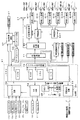
図10は、主基板(遊技制御基板)31における回路構成の一例を示すブロック図である。なお、図10には、払出制御基板37および演出制御基板80等も示されている。主基板31には、プログラムに従ってパチンコ遊技機1を制御する遊技制御用マイクロコンピュータ(遊技制御手段に相当)560が搭載されている。遊技制御用マイクロコンピュータ560は、ゲーム制御(遊技進行制御)用のプログラム等を記憶するROM54、ワークメモリとして使用される記憶手段としてのRAM55、プログラムに従って制御動作を行うCPU56、I/Oポート部57、およびパラレルデータをシリアルデータに変換して出力するシリアル出力回路を含む。この実施の形態では、ROM54およびRAM55は遊技制御用マイクロコンピュータ560に内蔵されている。すなわち、遊技制御用マイクロコンピュータ560は、1チップマイクロコンピュータである。1チップマイクロコンピュータには、少なくともCPU56のほかRAM55が内蔵されていればよく、ROM54は外付けであっても内蔵されていてもよい。また、I/Oポート部57は、外付けであってもよい。   FIG. 10 is a block diagram showing an example of the circuit configuration of the main board (game control board) 31. FIG. 10 also shows a payout control board 37, an effect control board 80, and the like. A game control microcomputer (corresponding to a game control means) 560 for controlling the pachinko gaming machine 1 according to a program is mounted on the main board 31. The game control microcomputer 560 includes a ROM 54 for storing a game control (game progress control) program and the like, a RAM 55 as storage means used as a work memory, a CPU 56 for performing control operations in accordance with the program, and an I / O port unit 57. And a serial output circuit for converting parallel data into serial data and outputting the serial data. In this embodiment, the ROM 54 and the RAM 55 are built in the game control microcomputer 560. That is, the game control microcomputer 560 is a one-chip microcomputer. The one-chip microcomputer only needs to incorporate at least the CPU 56 and the RAM 55, and the ROM 54 may be external or built-in. The I / O port unit 57 may be externally attached.

遊技制御用マイクロコンピュータ560には、ハードウェア乱数を発生する乱数回路503が接続されている。遊技制御用マイクロコンピュータ560は、乱数値を抽出するための条件が成立すると、乱数回路503から乱数値を読み出す。乱数回路503は、所定周波数のクロック信号を計数するカウンタであり、カウンタのカウント値が乱数値になる。乱数回路503に供給されている所定周波数のクロック信号は、監視回路(ウォッチドッグタイマ(WDT))504のクリア端子に入力されている。監視回路は、クリア端子に入力されるクロック信号の周波数よりも高い周波数のクロック信号を計数するカウンタであるが、クリア端子に入力されるクロック信号が例えばハイレベルになるとカウント値がリセットされる。よって、クリア端子に入力されるクロック信号が何らかの理由で停止した場合には、監視回路504はカウントアップする。監視回路504がカウントアップしたということは、乱数回路503にクロック信号が供給されていないことを示す。監視回路504は、カウントアップすると、乱数回路503が正常に動作していないことを示す乱数エラー信号を遊技制御用マイクロコンピュータ560に出力する。   A random number circuit 503 for generating hardware random numbers is connected to the game control microcomputer 560. The game control microcomputer 560 reads the random number value from the random number circuit 503 when the condition for extracting the random number value is satisfied. The random number circuit 503 is a counter that counts clock signals having a predetermined frequency, and the count value of the counter becomes a random value. A clock signal having a predetermined frequency supplied to the random number circuit 503 is input to a clear terminal of a monitoring circuit (watchdog timer (WDT)) 504. The monitoring circuit is a counter that counts a clock signal having a frequency higher than the frequency of the clock signal input to the clear terminal, but the count value is reset when the clock signal input to the clear terminal becomes high level, for example. Therefore, when the clock signal input to the clear terminal stops for some reason, the monitoring circuit 504 counts up. The fact that the monitoring circuit 504 has counted up indicates that no clock signal is supplied to the random number circuit 503. When counting up, the monitoring circuit 504 outputs a random number error signal indicating that the random number circuit 503 is not operating normally to the gaming control microcomputer 560.

なお、遊技制御用マイクロコンピュータ560においてCPU56がROM54に格納されているプログラムに従って制御を実行するので、以下、遊技制御用マイクロコンピュータ560(またはCPU56)が実行する(または、処理を行う)ということは、具体的には、CPU56がプログラムに従って制御を実行することである。このことは、主基板31以外の他の基板に搭載されているマイクロコンピュータについても同様である。   In the game control microcomputer 560, the CPU 56 executes control in accordance with the program stored in the ROM 54, so that the game control microcomputer 560 (or CPU 56) executes (or performs processing) hereinafter. Specifically, the CPU 56 executes control according to a program. The same applies to microcomputers mounted on substrates other than the main substrate 31.

また、ゲートスイッチ32a、第1始動口スイッチ13a、第2始動口スイッチ14a、カウントスイッチ23、入賞口スイッチ29a,30a,33a,39aからの検出信号を遊技制御用マイクロコンピュータ560に与える入力ドライバ回路58も主基板31に搭載されている。また、可変入賞球装置15を開閉するソレノイド16、および大入賞口を形成する特別可変入賞球装置20を開閉するソレノイド21を遊技制御用マイクロコンピュータ560からの指令に従って駆動する出力回路59も主基板31に搭載されている。   Also, an input driver circuit for supplying detection signals from the gate switch 32a, the first start port switch 13a, the second start port switch 14a, the count switch 23, and the winning port switches 29a, 30a, 33a and 39a to the game control microcomputer 560. 58 is also mounted on the main board 31. The main board also includes an output circuit 59 for driving the solenoid 16 for opening and closing the variable winning ball device 15 and the solenoid 21 for opening and closing the special variable winning ball device 20 that forms a big winning opening in accordance with a command from the game control microcomputer 560. 31.

また、遊技制御用マイクロコンピュータ560は、特別図柄を可変表示する特別図柄表示器8、普通図柄を可変表示する普通図柄表示器10、特別図柄保留記憶表示器18および普通図柄保留記憶表示器41の表示制御を行う。   In addition, the game control microcomputer 560 includes a special symbol display 8 that variably displays special symbols, a normal symbol display 10 that variably displays normal symbols, a special symbol hold memory display 18, and a normal symbol hold memory display 41. Perform display control.

また、遊技制御用マイクロコンピュータ560が搭載するシリアル出力回路78は、シフトレジスタなどによって構成され、CPU56が出力する演出制御コマンドをシリアルデータに変換して、中継基板77を介して演出制御基板80に送信する。また、シリアル出力回路78は、CPU56が出力する制御信号をシリアルデータに変換して、中継基板77を介して特別図柄表示器8や特別図柄保留記憶表示器18、普通図柄表示器10、普通図柄保留記憶表示器41に出力する。なお、特別図柄表示器8、特別図柄保留記憶表示器18、普通図柄表示器10および普通図柄保留記憶表示器41には、シリアルデータをパラレルデータに変換するシリアル−パラレル変換ICがそれぞれ設けられ、中継基板77からの制御信号をパラレルデータに変換して、特別図柄表示器8や特別図柄保留記憶表示器18、普通図柄表示器10、普通図柄保留記憶表示器41に供給される。   The serial output circuit 78 mounted on the game control microcomputer 560 is constituted by a shift register or the like. The serial control circuit 78 converts the presentation control command output from the CPU 56 into serial data, and sends it to the presentation control board 80 via the relay board 77. Send. The serial output circuit 78 converts the control signal output from the CPU 56 into serial data, and via the relay board 77, the special symbol display 8, the special symbol hold storage display 18, the normal symbol display 10, and the normal symbol. Output to the on-hold storage display 41. The special symbol display 8, the special symbol hold storage display 18, the normal symbol display 10 and the normal symbol hold storage display 41 are provided with serial-parallel conversion ICs for converting serial data into parallel data, respectively. The control signal from the relay board 77 is converted into parallel data and supplied to the special symbol display 8, the special symbol hold storage display 18, the normal symbol display 10, and the normal symbol hold storage display 41.

なお、遊技制御用マイクロコンピュータ560は、演出制御コマンドをパラレル信号形式で送信する出力回路を備えるようにし、CPU56が出力する演出制御コマンドをパラレル信号形式で演出制御基板80に送信してもよい。   The game control microcomputer 560 may include an output circuit that transmits the effect control command in the parallel signal format, and the effect control command output from the CPU 56 may be transmitted to the effect control board 80 in the parallel signal format.

なお、大当り遊技状態の発生を示す大当り情報等の情報出力信号を、情報端子盤(枠盤兼用外部端子基板)34を介してホールコンピュータ等の外部装置に対して出力する情報出力回路64も主基板31に搭載されている。情報端子盤34は、遊技機の裏面に設置されている。情報端子盤34には、払出制御基板37からの情報出力信号も入力される(図11参照)。   An information output circuit 64 that outputs an information output signal such as jackpot information indicating the occurrence of a jackpot gaming state to an external device such as a hall computer via an information terminal board (frame board / external terminal board) 34 is also mainly used. It is mounted on the substrate 31. The information terminal board 34 is installed on the back surface of the gaming machine. An information output signal from the payout control board 37 is also input to the information terminal board 34 (see FIG. 11).

また、遊技機の裏面には、遊技球を貯留する貯留タンクが設置され、貯留タンクに貯留された遊技球は球払出装置に至る。球払出装置の上部には、遊技媒体切れ検出手段としての球切れスイッチが設けられている。球切れスイッチが球切れを検出すると、球払出装置の払出動作が停止する。球切れスイッチは遊技球通路内の遊技球の有無を検出するスイッチであるが、貯留タンク内の補給球の不足を検出する球切れ検出スイッチも貯留タンクに近接する部分に設けられている。球切れ検出スイッチが遊技球の不足を検知すると、遊技機設置島に設けられている補給機構から遊技機に対して遊技球の補給が行われる。   In addition, a storage tank for storing game balls is installed on the back surface of the gaming machine, and the game balls stored in the storage tank reach the ball payout device. Above the ball payout device, a ball break switch as a game medium break detection means is provided. When the ball break switch detects a ball break, the dispensing operation of the ball dispensing device stops. The ball break switch is a switch for detecting the presence or absence of a game ball in the game ball passage, but a ball break detection switch for detecting the shortage of supply balls in the storage tank is also provided in a portion close to the storage tank. When the shortage of balls detection switch detects a shortage of game balls, the game balls are replenished from the replenishment mechanism provided on the gaming machine installation island.

入賞にもとづく景品としての遊技球や球貸し要求にもとづく遊技球が多数払い出されて打球供給皿3が満杯になると、遊技球は、余剰球通路を経て余剰球受皿4に導かれる。さらに遊技球が払い出されると、感知レバー(図示せず)が貯留状態検出手段としての満タンスイッチ(図示せず)を押圧して、貯留状態検出手段としての満タンスイッチがオンする。その状態では、球払出装置内の払出モータの回転が停止して球払出装置の動作が停止するとともに打球発射装置の駆動も停止する。   When a large number of game balls as prizes based on winning a prize and game balls based on a ball lending request are paid out and the hitting ball supply tray 3 is full, the game balls are guided to the surplus ball receiving tray 4 through the surplus ball passage. When the game ball is further paid out, a sensing lever (not shown) presses a full tank switch (not shown) as a storage state detection means, and the full tank switch as a storage state detection means is turned on. In this state, the rotation of the payout motor in the ball payout device is stopped, the operation of the ball payout device is stopped, and the driving of the ball hitting device is also stopped.

また、この実施の形態では、演出制御基板80に搭載されている演出制御手段(演出制御用マイクロコンピュータで構成される。)が、中継基板77を介して遊技制御用マイクロコンピュータ560からの演出制御コマンドをシリアル信号方式(シリアル通信方式:データを一つの信号線で送出する方式)で受信し、飾り図柄を可変表示する可変表示装置9の表示制御を行う。   Further, in this embodiment, the effect control means (configured by the effect control microcomputer) mounted on the effect control board 80 is used to provide effect control from the game control microcomputer 560 via the relay board 77. The command is received by a serial signal system (serial communication system: a system in which data is transmitted by one signal line), and display control of the variable display device 9 for variably displaying decorative symbols is performed.

また、演出制御基板80に搭載されている演出制御手段が、遊技盤6に設けられているセンター飾り用ランプ125a〜125fおよびステージランプ126a〜126fの表示制御を行うとともに、枠側に設けられている天枠ランプ281a〜281l、左枠ランプ282a〜282f、右枠ランプ283a〜283f、上皿ランプ82a〜82f、操作ボタンランプ83および下皿ランプ84a〜84fの表示制御を行い、スピーカ27からの音出力の制御を行う。   Further, the effect control means mounted on the effect control board 80 controls the display of the center decoration lamps 125a to 125f and the stage lamps 126a to 126f provided on the game board 6, and is provided on the frame side. Display frame lamps 281a to 281l, left frame lamps 282a to 282f, right frame lamps 283a to 283f, upper pan lamps 82a to 82f, operation button lamp 83 and lower pan lamps 84a to 84f. Controls sound output.

また、演出制御基板80の演出制御用マイクロコンピュータ100には、演出制御手段が出力する各ランプ125a〜125f,126a〜126f,281a〜281l,282a〜282f,283a〜283f,82a〜82f,83,84a〜84fを表示制御するための制御信号をパラレルデータからシリアルデータに変換するシリアル出力回路353が搭載されている。また、演出制御基板80の演出制御用マイクロコンピュータ100には、入力したシリアルデータをパラレルデータに変換して演出制御手段に出力するシリアル入力回路354が搭載されている。したがって、演出制御手段は、シリアル出力回路353を介して制御信号をシリアルデータ方式として出力することによって、各ランプ125a〜125f,126a〜126f,281a〜281l,282a〜282f,283a〜283f,82a〜82f,83,84a〜84fの表示制御(具体的には、発光制御すなわち点灯制御(点滅制御))を行う。   The effect control microcomputer 100 of the effect control board 80 includes lamps 125a to 125f, 126a to 126f, 281a to 281l, 282a to 282f, 283a to 283f, 82a to 82f, 83, which are output from the effect control means. A serial output circuit 353 for converting a control signal for display control of 84a to 84f from parallel data to serial data is mounted. In addition, the effect control microcomputer 100 of the effect control board 80 is equipped with a serial input circuit 354 that converts the input serial data into parallel data and outputs the parallel data to the effect control means. Therefore, the effect control means outputs the control signal as a serial data system via the serial output circuit 353, whereby the lamps 125a to 125f, 126a to 126f, 281a to 281l, 282a to 282f, 283a to 283f, 82a to 82a. Display control of 82f, 83, 84a to 84f (specifically, light emission control, that is, lighting control (flashing control)) is performed.

また、遊技盤側には、シリアルデータをパラレルデータに変換するためのシリアル−パラレル変換ICが搭載された盤側IC基板601が設けられている。盤側IC基板601は、中継基板606を介して演出制御基板80と接続される。また、遊技枠11側には、シリアルデータをパラレルデータに変換するためのシリアル−パラレル変換ICが搭載された各枠側IC基板602,603,604,605A,605Bが設けられている。各枠側IC基板602,603,604,605A,605Bは、中継基板606,607を介して演出制御基板80と接続される。   On the game board side, a board-side IC board 601 on which a serial-parallel conversion IC for converting serial data into parallel data is mounted. The board side IC substrate 601 is connected to the effect control substrate 80 via the relay substrate 606. On the game frame 11 side, frame-side IC substrates 602, 603, 604, 605A, and 605B on which serial-parallel conversion ICs for converting serial data into parallel data are mounted. Each frame side IC substrate 602, 603, 604, 605A, 605B is connected to the effect control substrate 80 via the relay substrate 606, 607.

なお、図10に示すように、演出制御基板80、中継基板606および中継基板607は、バス型に1系統の配線ルートで接続される。   As shown in FIG. 10, the effect control board 80, the relay board 606, and the relay board 607 are connected to each other by a single wiring route in a bus shape.

図11は、払出制御基板37および球払出装置97などの払出に関連する構成要素を示すブロック図である。図11に示すように、払出制御基板37には、払出制御用用CPU371を含む払出制御用マイクロコンピュータ(電気的に駆動される電気部品の制御を行う電気部品制御用マイクロコンピュータの一例)370が搭載されている。この実施の形態では、払出制御用マイクロコンピュータ370は、1チップマイクロコンピュータであり、少なくともRAMが内蔵されている。払出制御用CPU371、RAM(図示せず)、払出制御用プログラムを格納したROM(図示せず)およびI/Oポート等は、払出制御手段を構成する。すなわち、払出制御手段は、払出制御用CPU371、RAMおよびROMを有する払出制御用マイクロコンピュータ370と、I/Oポートとで実現される。また、I/Oポートは、払出制御用マイクロコンピュータ370に内蔵されていてもよい。   FIG. 11 is a block diagram showing components related to payout, such as the payout control board 37 and the ball payout device 97. As shown in FIG. 11, the payout control board 37 includes a payout control microcomputer 370 including an payout control CPU 371 (an example of an electric component control microcomputer that controls electrically driven electric components). It is installed. In this embodiment, the payout control microcomputer 370 is a one-chip microcomputer and incorporates at least a RAM. The payout control CPU 371, the RAM (not shown), the ROM (not shown) storing the payout control program, the I / O port, and the like constitute the payout control means. That is, the payout control means is realized by a payout control CPU 371, a payout control microcomputer 370 having a RAM and a ROM, and an I / O port. The I / O port may be built in the payout control microcomputer 370.

球切れスイッチ187、満タンスイッチ48の検出信号は、中継基板72を介して払出制御基板37のI/Oポート372fに入力される。払出個数カウントスイッチ301の検出信号は、中継基板72を介して払出制御基板37のI/Oポート372eに入力される。また、払出モータ位置センサ295からの検出信号は、中継基板72を介して払出制御基板37のI/Oポート372eに入力される。払出モータ289は、球払出装置97に設けられ、回転することによって、遊技機の裏面において貯留されている払出用の遊技球を払い出す。払出モータ位置センサ295は、払出モータ289の回転位置を検出するための発光素子(LED)と受光素子とによるセンサであり、遊技球が詰まったこと、すなわち、いわゆる球噛みを検出するために用いられる。払出制御基板37に搭載されている払出制御用マイクロコンピュータ370は、球切れスイッチ187からの検出信号が球切れ状態を示していたり、満タンスイッチ48からの検出信号が満タン状態を示していると、球払出処理を停止する。さらに、満タンスイッチ48からの検出信号が満タン状態を示していると、打球発射装置からの球発射を停止させる。なお、満タンスイッチ48からの検出信号が満タン状態を示していても、打球発射装置からの球発射を停止させないようにしてもよい。また、打球発射装置に遊技制御用マイクロコンピュータ560からの信号線が接続されるように構成されている場合には、遊技制御用マイクロコンピュータ560が打球発射装置からの球発射を停止させるようにしてもよい。   Detection signals from the ball break switch 187 and the full tank switch 48 are input to the I / O port 372 f of the payout control board 37 via the relay board 72. The detection signal of the payout number count switch 301 is input to the I / O port 372e of the payout control board 37 via the relay board 72. A detection signal from the payout motor position sensor 295 is input to the I / O port 372e of the payout control board 37 via the relay board 72. The payout motor 289 is provided in the ball payout device 97 and rotates to pay out payout game balls stored on the back surface of the game machine. The payout motor position sensor 295 is a sensor composed of a light emitting element (LED) and a light receiving element for detecting the rotational position of the payout motor 289, and is used for detecting that the game ball is clogged, that is, so-called ball biting. It is done. In the payout control microcomputer 370 mounted on the payout control board 37, the detection signal from the ball break switch 187 indicates that the ball is out of ball, or the detection signal from the full tank switch 48 indicates that the ball is full. Then, the ball payout process is stopped. Furthermore, when the detection signal from the full tank switch 48 indicates a full tank state, the ball launching from the ball striking device is stopped. Note that even when the detection signal from the full tank switch 48 indicates a full state, the ball firing from the ball striking device may not be stopped. When the signal line from the game control microcomputer 560 is connected to the ball hitting device, the game control microcomputer 560 stops the ball shot from the ball hitting device. Also good.

入賞口への遊技球の入賞があると、主基板31の出力回路67から、払出指令信号として、払い出すべき賞球個数を示す賞球個数信号(払出数データ)および賞球個数信号の取り込み(受信)を要求する賞球REQ信号(取込要求信号)が出力(送信)される。具体的には、オン状態になる。賞球個数信号は、4ビットのデータ(2進4桁のデータ)によって構成され、4本の信号線によって出力される。なお、信号のオン状態すなわち出力状態は、信号が有意である状態であり、オン状態になることは、信号を受ける側に対してその信号にもとづく何らかの処理を開始することを指令することを意味する。例えば、賞球個数を示す賞球個数信号および賞球REQ信号がオン状態になるということは、払出制御用マイクロコンピュータ370に対して、賞球個数信号が示す払出数を認識するように指令することを意味する。また、信号を出力することによってオン状態とし、信号出力を停止することによってオフ状態としてもよいが、オン状態にするときにはオン状態に応じた信号を出力し、オフ状態にするときにはオフ状態に応じた信号を出力することによって、オン状態とオフ状態とを切り替えてもよい。   When there is a winning game ball at the winning opening, a prize ball number signal (payout number data) indicating the number of prize balls to be paid out and a prize ball number signal are fetched from the output circuit 67 of the main board 31 as a payout command signal. A prize ball REQ signal (capture request signal) requesting (reception) is output (transmitted). Specifically, it is turned on. The award ball number signal is composed of 4-bit data (binary 4-digit data) and is output through four signal lines. Note that the on state of the signal, that is, the output state is a state where the signal is significant, and turning on means that the signal receiving side is instructed to start some processing based on the signal. To do. For example, when the prize ball number signal indicating the number of prize balls and the prize ball REQ signal are turned on, the microcomputer 370 is commanded to recognize the number of prizes indicated by the prize ball number signal. Means that. Alternatively, the signal may be turned on by outputting a signal, and the signal may be turned off by stopping the signal output. However, a signal corresponding to the on state is output when the signal is turned on, and the signal is output according to the off condition when the signal is turned off. Alternatively, the on state and the off state may be switched by outputting a signal.

賞球REQ信号および賞球個数信号は、入力回路373Aを介してI/Oポート372eに入力される。払出制御用マイクロコンピュータ370は、I/Oポート372eを介して賞球個数信号を入力すると、賞球個数信号が示す個数の遊技球を払い出すために球払出装置97を駆動する制御を行う。なお、賞球REQ信号および賞球個数信号は、払出数を指定する払出指令信号に相当する。   The prize ball REQ signal and the prize ball number signal are input to the I / O port 372e via the input circuit 373A. When the payout control microcomputer 370 receives the prize ball number signal via the I / O port 372e, the payout control microcomputer 370 controls to drive the ball payout device 97 to pay out the number of game balls indicated by the prize ball number signal. The prize ball REQ signal and the prize ball number signal correspond to a payout command signal for designating the number of payouts.

払出制御用マイクロコンピュータ370は、出力ポート372gを介して、賞球払出数を示す賞球情報信号および貸し球数を示す球貸し個数信号を情報端子盤(枠盤兼用外部端子基板)34に出力する。なお、出力ポート372gの外側に、ドライバ回路が設置されているが、図11では記載省略されている。   The payout control microcomputer 370 outputs a prize ball information signal indicating the number of prize balls paid out and a ball rental number signal indicating the number of balls lent to the information terminal board (frame board / external terminal board) 34 via the output port 372g. To do. Although a driver circuit is installed outside the output port 372g, the description is omitted in FIG.

また、払出制御用マイクロコンピュータ370は、出力ポート372cを介して、7セグメントLEDによるエラー表示用LED374にエラー信号を出力する。なお、払出制御基板37の入力ポート372fには、エラー状態を解除するためのエラー解除スイッチ375からの検出信号が入力される。エラー解除スイッチ375は、ソフトウェアリセットによってエラー状態を解除するために用いられる。   Also, the payout control microcomputer 370 outputs an error signal to the error display LED 374 using a 7-segment LED via the output port 372c. A detection signal from an error release switch 375 for releasing the error state is input to the input port 372f of the payout control board 37. The error cancel switch 375 is used to cancel the error state by software reset.

さらに、払出制御用マイクロコンピュータ370からの払出モータ289への駆動信号は、出力ポート372aおよび中継基板72を介して球払出装置97の払出機構部分における払出モータ289に伝えられる。なお、出力ポート372aの外側に、ドライバ回路(モータ駆動回路)が設置されているが、図11では記載省略されている。   Further, a drive signal from the payout control microcomputer 370 to the payout motor 289 is transmitted to the payout motor 289 in the payout mechanism portion of the ball payout device 97 via the output port 372a and the relay board 72. A driver circuit (motor drive circuit) is installed outside the output port 372a, but is not shown in FIG.

遊技機に隣接して設置されているカードユニット50には、カードユニット制御用マイクロコンピュータが搭載されている。また、カードユニット50には、使用可表示ランプ、連結台方向表示器、カード投入表示ランプおよびカード挿入口が設けられている。インタフェース基板(中継基板)66には、打球供給皿3の近傍に設けられている度数表示LED60、球貸し可LED61、球貸しスイッチ62および返却スイッチ63(図1において図示せず)が接続される。   A card unit control microcomputer is mounted on the card unit 50 installed adjacent to the gaming machine. In addition, the card unit 50 is provided with a usable display lamp, a connecting table direction indicator, a card insertion display lamp, and a card insertion slot. The interface board (relay board) 66 is connected to a power display LED 60, a ball lending LED 61, a ball lending switch 62, and a return switch 63 (not shown in FIG. 1) provided in the vicinity of the hitting ball supply tray 3. .

インタフェース基板66からカードユニット50には、遊技者の操作に応じて、球貸しスイッチ62が操作されたことを示す球貸しスイッチ信号および返却スイッチ63が操作されたことを示す返却スイッチ信号が与えられる。また、カードユニット50からインタフェース基板66には、プリペイドカードの残高を示すカード残高表示信号および球貸し可表示信号が与えられる。カードユニット50と払出制御基板37の間では、接続信号(VL信号)、ユニット操作信号(BRDY信号)、球貸し要求信号(BRQ信号)、球貸し完了信号(EXS信号)およびパチンコ機動作信号(PRDY信号)が入力ポート372fおよび出力ポート372dを介して送受信される。カードユニット50と払出制御基板37の間には、インタフェース基板66が介在している。よって、接続信号(VL信号)等の信号は、図11に示すように、インタフェース基板66を介してカードユニット50と払出制御基板37の間で送受信されることになる。   A card lending switch signal indicating that the ball lending switch 62 has been operated and a return switch signal indicating that the return switch 63 has been operated are provided to the card unit 50 from the interface board 66 in accordance with the player's operation. . Further, a card balance display signal indicating a prepaid card balance and a ball lending display signal are given from the card unit 50 to the interface board 66. Between the card unit 50 and the payout control board 37, a connection signal (VL signal), a unit operation signal (BRDY signal), a ball lending request signal (BRQ signal), a ball lending completion signal (EXS signal) and a pachinko machine operation signal ( PRDY signal) is transmitted / received via the input port 372f and the output port 372d. An interface board 66 is interposed between the card unit 50 and the payout control board 37. Therefore, a signal such as a connection signal (VL signal) is transmitted and received between the card unit 50 and the payout control board 37 via the interface board 66 as shown in FIG.

パチンコ遊技機1の電源が投入されると、払出制御基板37に搭載されている払出制御用マイクロコンピュータ370は、カードユニット50にPRDY信号を出力する。また、カードユニット制御用マイクロコンピュータは、電源が投入されると、VL信号を出力する。払出制御用マイクロコンピュータ370は、VL信号の入力状態によってカードユニット50の接続状態/未接続状態を判定する。カードユニット50においてカードが受け付けられ、球貸しスイッチが操作され球貸しスイッチ信号が入力されると、カードユニット制御用マイクロコンピュータは、払出制御基板37にBRDY信号を出力する。この時点から所定の遅延時間が経過すると、カードユニット制御用マイクロコンピュータは、払出制御基板37にBRQ信号を出力する。   When the power of the pachinko gaming machine 1 is turned on, the payout control microcomputer 370 mounted on the payout control board 37 outputs a PRDY signal to the card unit 50. The card unit control microcomputer outputs a VL signal when the power is turned on. The payout control microcomputer 370 determines the connected / unconnected state of the card unit 50 according to the input state of the VL signal. When a card is received in the card unit 50, the ball lending switch is operated and a ball lending switch signal is input, the card unit control microcomputer outputs a BRDY signal to the payout control board 37. When a predetermined delay time elapses from this point, the card unit control microcomputer outputs a BRQ signal to the payout control board 37.

そして、払出制御用マイクロコンピュータ370は、カードユニット50に対するEXS信号を立ち上げ、カードユニット50からのBRQ信号の立ち下がりを検出すると、払出モータ289を駆動し、所定個の貸し球を遊技者に払い出す。そして、払出が完了したら、払出制御用マイクロコンピュータ370は、カードユニット50に対するEXS信号を立ち下げる。その後、カードユニット50からのBRDY信号がオン状態でないことを条件に、遊技制御手段から払出指令信号を受けると賞球払出制御を実行する。   Then, the payout control microcomputer 370 raises the EXS signal to the card unit 50 and, when detecting the fall of the BRQ signal from the card unit 50, drives the payout motor 289 to give a predetermined number of rental balls to the player. Pay out. When the payout is completed, the payout control microcomputer 370 causes the EXS signal to the card unit 50 to fall. Thereafter, when a BRDY signal from the card unit 50 is not in an ON state, a prize ball payout control is executed when a payout command signal is received from the game control means.

なお、この実施の形態では、カードユニット50が遊技機とは別体として遊技機に隣接して設置されている場合を例にするが、カードユニット50は遊技機と一体化されていてもよい。また、コイン投入に応じてその金額に応じた遊技球が貸し出されるような場合でも本発明を適用できる。   In this embodiment, the case where the card unit 50 is installed adjacent to the gaming machine as a separate body from the gaming machine is taken as an example, but the card unit 50 may be integrated with the gaming machine. . Further, the present invention can be applied even in the case where game balls corresponding to the amount of money are lent out in accordance with coin insertion.

また、ドア開放センサ155の検出信号が、払出制御基板37に入力される。払出制御基板37において、ドア開放センサ155の検出信号は、払出制御用マイクロコンピュータ370には入力されず、出力回路373Bを介して主基板31に出力される。なお、出力回路373Bを介さずに主基板31に出力されるようにしてもよい。また、払出制御用マイクロコンピュータ370は、満タンスイッチ48、球切れスイッチ187および払出個数カウントスイッチ301の検出信号に相当する信号を出力ポート372bおよび出力回路373Bを介して主基板31に出力する。しかし、払出制御用マイクロコンピュータ370に入力される満タンスイッチ48、球切れスイッチ187および払出個数カウントスイッチ301の検出信号を、払出制御基板37において分岐させ、分岐された検出信号を出力回路373Bを介して主基板31に出力するように構成してもよい。そのように構成した場合には、払出制御用マイクロコンピュータ370は、満タンスイッチ48、球切れスイッチ187および払出個数カウントスイッチ301の検出信号に相当する信号を出力ポート372bから出力する必要はない。   Further, the detection signal of the door opening sensor 155 is input to the payout control board 37. In the payout control board 37, the detection signal of the door opening sensor 155 is not input to the payout control microcomputer 370 but is output to the main board 31 via the output circuit 373B. The output may be output to the main board 31 without going through the output circuit 373B. Further, the payout control microcomputer 370 outputs signals corresponding to detection signals of the full switch 48, the ball break switch 187, and the payout number count switch 301 to the main board 31 via the output port 372b and the output circuit 373B. However, the detection signals of the full tank switch 48, the ball break switch 187 and the payout count switch 301 that are input to the payout control microcomputer 370 are branched at the payout control board 37, and the branched detection signal is output to the output circuit 373B. Via the main board 31. In such a configuration, the payout control microcomputer 370 need not output from the output port 372b signals corresponding to the detection signals of the full tank switch 48, the ball break switch 187, and the payout number count switch 301.

なお、払出制御基板37に入力されたドア開放センサ155の検出信号を、さらに主基板31を介して情報出力回路64から情報端子盤34に出力するようにしてもよい。この場合、ドア開放センサ155の検出信号を、遊技制御用マイクロコンピュータ560および払出制御用マイクロコンピュータ370ともに入力することなく、そのまま主制御基板31および払出制御基板37を介して情報端子盤34に出力するようにしてもよい。   The detection signal of the door opening sensor 155 input to the payout control board 37 may be further output from the information output circuit 64 to the information terminal board 34 via the main board 31. In this case, the detection signal of the door opening sensor 155 is directly output to the information terminal board 34 via the main control board 31 and the payout control board 37 without being input to both the game control microcomputer 560 and the payout control microcomputer 370. You may make it do.

図12は、中継基板77および演出制御基板80の回路構成例を示すブロック図である。なお、図12に示す例では、演出制御に関して演出制御基板80のみを設ける場合を示すが、ランプドライバ基板および音声出力基板を設けてもよい。この場合、ランプドライバ基板および音声出力基板には、マイクロコンピュータは搭載されていないが、マイクロコンピュータを搭載してもよい。   FIG. 12 is a block diagram illustrating a circuit configuration example of the relay board 77 and the effect control board 80. In addition, although the example shown in FIG. 12 shows the case where only the effect control board 80 is provided regarding effect control, you may provide a lamp driver board | substrate and an audio | voice output board | substrate. In this case, the lamp driver board and the sound output board are not equipped with a microcomputer, but may be equipped with a microcomputer.

演出制御基板80は、演出制御用CPU101、RAM(図示せず)、シリアル出力回路353、シリアル入力回路354、クロック信号出力部356および入力取込信号出力部357を含む演出制御用マイクロコンピュータ100を搭載している。なお、RAMは外付けであってもよい。演出制御基板80において、演出制御用CPU101は、内蔵または外付けのROM(図示せず)に格納されたプログラムに従って動作し、シリアル入力回路102および入力ポート103を介して演出制御コマンドを受信する。この場合、シリアル入力回路102は、シリアルデータ方式として受信した演出制御コマンドをパラレルデータに変換し出力する。また、演出制御用CPU101は、演出制御コマンドにもとづいて、VDP(ビデオディスプレイプロセッサ)109に可変表示装置9の表示制御を行わせる。   The effect control board 80 includes an effect control microcomputer 100 including an effect control CPU 101, a RAM (not shown), a serial output circuit 353, a serial input circuit 354, a clock signal output unit 356 and an input capture signal output unit 357. It is installed. The RAM may be externally attached. In the effect control board 80, the effect control CPU 101 operates in accordance with a program stored in a built-in or external ROM (not shown), and receives an effect control command via the serial input circuit 102 and the input port 103. In this case, the serial input circuit 102 converts the effect control command received as the serial data method into parallel data and outputs the parallel data. Further, the effect control CPU 101 causes the VDP (video display processor) 109 to perform display control of the variable display device 9 based on the effect control command.

この実施の形態では、演出制御用マイクロコンピュータ100と共動して可変表示装置9の表示制御を行うVDP109が演出制御基板80に搭載されている。VDP109は、演出制御用マイクロコンピュータ100とは独立したアドレス空間を有し、そこにVRAMをマッピングする。VRAMは、画像データを展開するためのバッファメモリである。そして、VDP109は、VRAM内の画像データをフレームメモリを介して可変表示装置9に出力する。   In this embodiment, a VDP 109 that performs display control of the variable display device 9 in cooperation with the effect control microcomputer 100 is mounted on the effect control board 80. The VDP 109 has an address space independent of the production control microcomputer 100, and maps a VRAM therein. VRAM is a buffer memory for developing image data. The VDP 109 outputs the image data in the VRAM to the variable display device 9 via the frame memory.

演出制御用CPU101は、受信した演出制御コマンドに従ってCGROM(図示せず)から必要なデータを読み出すための指令をVDP109に出力する。CGROMは、可変表示装置9に表示されるキャラクタ画像データや動画像データ、具体的には、人物、文字、図形や記号等(飾り図柄を含む)、および背景画像のデータをあらかじめ格納しておくためのROMである。VDP109は、演出制御用CPU101の指令に応じて、CGROMから画像データを読み出す。そして、VDP109は、読み出した画像データにもとづいて表示制御を実行する。   The effect control CPU 101 outputs to the VDP 109 a command for reading out necessary data from a CGROM (not shown) in accordance with the received effect control command. The CGROM stores character image data and moving image data displayed on the variable display device 9, specifically, a person, characters, figures, symbols, etc. (including decorative designs), and background image data in advance. ROM. The VDP 109 reads image data from the CGROM in response to the instruction from the effect control CPU 101. The VDP 109 executes display control based on the read image data.

中継基板77には、主基板31から入力された信号を演出制御基板80に向かう方向にしか通過させない(演出制御基板80から中継基板77への方向には信号を通過させない)信号方向規制手段としての単方向性回路74が搭載されている。単方向性回路として、例えばダイオードやトランジスタが使用される。図12には、ダイオードが例示されている。   As a signal direction regulating means, the signal inputted from the main board 31 is allowed to pass through the relay board 77 only in the direction toward the effect control board 80 (the signal is not passed in the direction from the effect control board 80 to the relay board 77). The unidirectional circuit 74 is mounted. For example, a diode or a transistor is used as the unidirectional circuit. FIG. 12 illustrates a diode.

さらに、演出制御用CPU101は、シリアル出力回路353を介してランプを駆動する信号を出力する。シリアル出力回路は、入力したランプのLEDを駆動する信号(パラレルデータ)をシリアルデータに変換して中継基板606に出力する。また、演出制御用CPU101は、音声合成用IC173に対して音番号データを出力する。   Further, the effect control CPU 101 outputs a signal for driving the lamp via the serial output circuit 353. The serial output circuit converts the input signal (parallel data) for driving the LED of the lamp into serial data and outputs the serial data to the relay board 606. Further, the production control CPU 101 outputs the sound number data to the speech synthesis IC 173.

また、クロック信号出力部356は、クロック信号を中継基板606に出力する。クロック信号出力部356からのクロック信号は、中継基板606,607を介して各枠側IC基板602,603,604,604A,605Bに搭載されたシリアル−パラレル変換IC610〜615や入力IC620に供給される。また、クロック信号出力部356からのクロック信号は、中継基板606を介して盤側IC基板601に搭載されたシリアル−パラレル変換IC616〜618や入力IC621に供給される。したがって、この実施の形態では、各シリアル−パラレル変換IC610〜618および各入力IC620,621に共通のクロック信号が供給されることになる。   Further, the clock signal output unit 356 outputs a clock signal to the relay board 606. The clock signal from the clock signal output unit 356 is supplied to the serial-parallel conversion ICs 610 to 615 and the input IC 620 mounted on the frame side IC boards 602, 603, 604, 604A, and 605B via the relay boards 606 and 607. The The clock signal from the clock signal output unit 356 is supplied to the serial-parallel conversion ICs 616 to 618 and the input IC 621 mounted on the board side IC substrate 601 via the relay substrate 606. Therefore, in this embodiment, a common clock signal is supplied to each of the serial-parallel conversion ICs 610 to 618 and the input ICs 620 and 621.

また、入力取込信号出力部357は、演出制御用CPU101の指示に従って、中継基板606,607を介して、盤側IC基板601または枠側IC基板602,603,604,604A,605Bに入力取込信号(ラッチ信号)を出力する。枠側IC基板605Aに搭載された入力IC620は、演出制御用マイクロコンピュータ100からの入力取込信号を入力すると、操作ボタン81a〜81eの検出信号をラッチし、シリアルデータ方式として中継基板606,607を介して演出制御用マイクロコンピュータ100に出力する。また、盤側IC基板601に搭載された入力IC621は、演出制御用マイクロコンピュータ100からの入力取込信号を入力すると、各位置センサ151b,152bの検出信号をラッチし、シリアルデータ方式として中継基板606を介して演出制御用マイクロコンピュータ100に出力する。   In addition, the input capture signal output unit 357 receives input to the board side IC board 601 or the frame side IC boards 602, 603, 604, 604A, and 605B via the relay boards 606 and 607 in accordance with the instruction of the effect control CPU 101. Output a latch signal. When the input IC 620 mounted on the frame side IC board 605A receives an input capture signal from the production control microcomputer 100, the detection signals of the operation buttons 81a to 81e are latched, and the relay boards 606 and 607 are serial data systems. To the production control microcomputer 100. The input IC 621 mounted on the board-side IC board 601 latches the detection signals of the position sensors 151b and 152b when an input input signal from the production control microcomputer 100 is input, and relays the serial board as a serial data system. It outputs to the production control microcomputer 100 via 606.

音声合成用IC173は、音番号データを入力すると、音番号データに応じた音声や効果音を発生し増幅回路175に出力する。増幅回路175は、音声合成用IC173の出力レベルを、ボリューム176で設定されている音量に応じたレベルに増幅した音声信号をスピーカ27に出力する。音声データROM174には、音番号データに応じた制御データが格納されている。音番号データに応じた制御データは、所定期間(例えば飾り図柄の変動期間)における効果音または音声の出力態様を時系列的に示すデータの集まりである。   When the sound number IC 173 receives the sound number data, the sound synthesizing IC 173 generates a sound or a sound effect corresponding to the sound number data and outputs it to the amplifier circuit 175. The amplifier circuit 175 outputs an audio signal obtained by amplifying the output level of the speech synthesis IC 173 to a level corresponding to the volume set by the volume 176 to the speaker 27. The voice data ROM 174 stores control data corresponding to the sound number data. The control data corresponding to the sound number data is a collection of data indicating the sound effect or sound output mode in a time series in a predetermined period (for example, a decorative symbol variation period).

図13は、情報端子盤34の構成例を示すブロック図である。図13に示す例では、情報端子盤34には、ケーブル343およびコネクタ341を介して主基板31から信号が入力され、ケーブル344およびコネクタ342を介して払出制御基板37から信号が入力される。そして、ケーブル343を介して入力された信号は、ドライバ回路345、コネクタ347およびケーブル349を介して、例えばホールコンピュータに対して出力される。また、ケーブル344を介して入力された信号は、ドライバ回路346、コネクタ348およびケーブル349を介して、例えばホールコンピュータに対して出力される。   FIG. 13 is a block diagram illustrating a configuration example of the information terminal board 34. In the example shown in FIG. 13, a signal is input to the information terminal board 34 from the main board 31 via the cable 343 and the connector 341, and a signal is input from the payout control board 37 via the cable 344 and the connector 342. A signal input via the cable 343 is output to, for example, a hall computer via the driver circuit 345, the connector 347, and the cable 349. A signal input via the cable 344 is output to, for example, a hall computer via the driver circuit 346, the connector 348, and the cable 349.

なお、図13に示す情報端子盤(枠盤兼用外部端子基板)34において、図13における上側の部分(コネクタ341、ドライバ回路345およびコネクタ347が設けられている領域)は盤用外部端子基板に相当し、下側の部分(コネクタ342、ドライバ回路346およびコネクタ348が設けられている領域)は枠用外部端子基板に相当する。すなわち、主基板31からの信号に関する部分か、払出制御基板37からの信号(例えば、払出制御基板37からの情報出力信号(具体的には、賞球払出数を示す賞球情報信号や、貸し球数を示す球貸し個数信号))に関する部分かを容易に判別できる。   In the information terminal board (frame board / external terminal board) 34 shown in FIG. 13, the upper part (area where the connector 341, driver circuit 345 and connector 347 are provided) in FIG. The lower portion (the region where the connector 342, the driver circuit 346, and the connector 348 are provided) corresponds to the frame external terminal board. That is, a part related to a signal from the main board 31 or a signal from the payout control board 37 (for example, an information output signal from the payout control board 37 (specifically, a prize ball information signal indicating the number of prize balls paid out or a lending) It is possible to easily determine whether the portion is related to a ball lending number signal indicating the number of balls)).

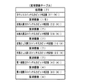
図14は、遊技制御手段における出力ポートの割り当ての例を示す説明図である。図14に示すように、出力ポート0は払出制御基板37に送信される払出指令信号の出力ポートである。なお、図14に示された「論理」(例えば1がオン状態)と逆の論理(例えば0がオン状態)を用いてもよい。   FIG. 14 is an explanatory diagram showing an example of output port assignment in the game control means. As shown in FIG. 14, the output port 0 is an output port for a payout command signal transmitted to the payout control board 37. Note that the logic (eg, 0 is on) opposite to the “logic” (eg, 1 is on) shown in FIG. 14 may be used.

出力ポート1から、大入賞口を開閉する可変入賞球装置20を開閉するためのソレノイド(大入賞口扉ソレノイド)21および可変入賞球装置15を開閉するためのソレノイド(普通電動役物ソレノイド)16に対する駆動信号が出力される。なお、出力ポート0,1は、図1に示されたI/Oポート部57の一部である。また、信号がオン状態になっているときが、「信号が出力されている」状態に相当する。   From the output port 1, a solenoid (large winning opening door solenoid) 21 for opening and closing a variable winning ball apparatus 20 for opening and closing a large winning opening and a solenoid (ordinary electric accessory solenoid) 16 for opening and closing the variable winning ball apparatus 15 are opened. The drive signal for is output. Output ports 0 and 1 are part of the I / O port unit 57 shown in FIG. Further, the time when the signal is in the ON state corresponds to the state where the “signal is being output”.

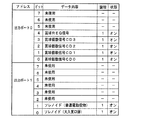
図15は、遊技制御手段における入力ポートのビット割り当ての例を示す説明図である。図15に示すように、入力ポート0のビット0〜7には、それぞれ、カウントスイッチ23、ゲートスイッチ32a、入賞口スイッチ33a,39a,29a,30a、第2始動口スイッチ14a、第1始動口スイッチ13aの検出信号が入力される。   FIG. 15 is an explanatory diagram showing an example of bit assignment of input ports in the game control means. As shown in FIG. 15, the bits 0 to 7 of the input port 0 have a count switch 23, a gate switch 32a, winning port switches 33a, 39a, 29a, 30a, a second starting port switch 14a, and a first starting port, respectively. A detection signal of the switch 13a is input.

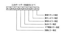
また、入力ポート1のビット0〜4には、それぞれ、払出制御基板37からの賞球カウント信号、満タン信号、球切れ信号、払出エラー信号、ドア開閉信号が入力される。賞球カウント信号のハイレベル「1」がオン状態(払出個数カウントスイッチ301がオンした状態)に対応する。満タン信号のハイレベル「1」がオン状態(満タンスイッチ48がオンした状態)に対応する。球切れ信号のハイレベル「1」がオン状態(球切れスイッチ187がオンした状態)に対応する。ドア開閉信号のハイレベル「1」は、ドア開放センサ155が遊技枠11の開放を検出していない状態(ドアが閉鎖している状態)に対応する。   In addition, the winning ball count signal, the full tank signal, the ball runout signal, the payout error signal, and the door opening / closing signal from the payout control board 37 are input to bits 0 to 4 of the input port 1, respectively. The high level “1” of the prize ball count signal corresponds to the ON state (the state where the payout number count switch 301 is ON). The high level “1” of the full signal corresponds to the on state (the full switch 48 is on). The high level “1” of the ball break signal corresponds to the on state (the state in which the ball break switch 187 is turned on). A high level “1” of the door opening / closing signal corresponds to a state where the door opening sensor 155 does not detect the opening of the game frame 11 (a state where the door is closed).

入力ポート1のビット5には、監視回路504からの乱数エラー信号が入力される。乱数エラー信号のローレベル(「0」)がオン状態(乱数エラーが生じた状態)に対応する。すなわち、監視回路504は、正常時には乱数エラー信号をハイレベルに維持しているが、異常時には乱数エラー信号をローレベルに変化させる。なお、図15に示された「論理」と逆の論理を用いてもよい。例えば、1がオン状態である入力信号を0をオン状態である入力信号にしてもよい。   A random number error signal from the monitoring circuit 504 is input to bit 5 of the input port 1. The low level (“0”) of the random number error signal corresponds to the ON state (the state where the random number error has occurred). That is, the monitoring circuit 504 maintains the random number error signal at a high level when normal, but changes the random number error signal to a low level when abnormal. Note that a logic opposite to the “logic” shown in FIG. 15 may be used. For example, an input signal in which 1 is on may be an input signal in which 0 is on.

入力ポート2のビット0,1には、それぞれ、電源基板からの電源断信号およびクリアスイッチの検出信号(クリア信号)が入力される。電源断信号は、電源基板に搭載されている電源監視回路が所定電圧の低下を検出したときに出力する信号である。クリアスイッチは遊技店員等が操作可能なスイッチあり、RAM55を初期化したいときに操作されるスイッチである。なお、入力ポート0〜2は、図1に示されたI/Oポート部57の一部である。また、信号がオン状態になっているときが、「信号が入力されている」状態に相当する。   Bits 0 and 1 of the input port 2 are supplied with a power-off signal from the power supply board and a clear switch detection signal (clear signal), respectively. The power-off signal is a signal that is output when a power supply monitoring circuit mounted on the power supply board detects a decrease in a predetermined voltage. The clear switch is a switch that can be operated by a game clerk or the like, and is a switch that is operated when the RAM 55 is to be initialized. The input ports 0 to 2 are a part of the I / O port unit 57 shown in FIG. Further, the time when the signal is in the ON state corresponds to the state where the “signal is input”.

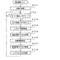
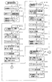
図16は、演出制御基板80、中継基板606,607、盤側IC基板601、枠側IC基板602,603,604,605A,605Bの構成例を示すブロック図である。演出制御基板80の演出制御用マイクロコンピュータ100は、制御信号としてのシリアルデータとともに、クロック信号を中継基板606に出力する。また、入力IC620,621に入力信号をラッチさせるための入力取込信号を中継基板606に出力する。   FIG. 16 is a block diagram illustrating a configuration example of the effect control board 80, the relay boards 606 and 607, the board side IC board 601, and the frame side IC boards 602, 603, 604, 605A, and 605B. The effect control microcomputer 100 of the effect control board 80 outputs a clock signal to the relay board 606 together with serial data as a control signal. In addition, an input capture signal for causing the input ICs 620 and 621 to latch the input signal is output to the relay board 606.

中継基板606は、演出制御用マイクロコンピュータ100から入力したシリアルデータおよびクロック信号を、盤側IC基板601に搭載された各シリアル−パラレル変換IC616〜618に供給する。そして、各シリアル−パラレル変換IC616〜618は、入力したシリアルデータをパラレルデータに変換して、遊技盤6に設けられた各ランプのLED125a〜125f,126a〜126fや、各可動部材のモータ151a,152aに供給する。   The relay board 606 supplies the serial data and the clock signal input from the production control microcomputer 100 to the serial-parallel conversion ICs 616 to 618 mounted on the board side IC board 601. And each serial-parallel conversion IC616-618 converts the input serial data into parallel data, LED125a-125f of each lamp provided in the game board 6, 126a-126f, motor 151a of each movable member, It supplies to 152a.

また、中継基板607は、バス型に1系統の配線ルートで中継基板606と接続されており、各シリアル−パラレル変換IC616〜618に接続されるシリアルデータ線300およびクロック信号線301は、盤側IC基板601上でバス形式に接続されている。なお、バス型に接続とは、1つの配線ルートに複数のシリアル−パラレル変換ICまたは中継基板が接続されていることである。   Further, the relay board 607 is connected to the relay board 606 through a single wiring route in a bus type, and the serial data line 300 and the clock signal line 301 connected to each serial-parallel conversion IC 616 to 618 are connected to the board side. It is connected to the bus form on the IC substrate 601. The connection to the bus type means that a plurality of serial-parallel conversion ICs or relay boards are connected to one wiring route.

また、盤側IC基板601に搭載された各シリアル−パラレル変換IC616〜618にはそれぞれ固有のIDがある。この実施の形態では、図16に示すように、IC616のIDは06であり、IC617のIDは07であり、IC618のIDは08である。   Each serial-parallel conversion IC 616 to 618 mounted on the board-side IC board 601 has a unique ID. In this embodiment, as shown in FIG. 16, the ID of IC 616 is 06, the ID of IC 617 is 07, and the ID of IC 618 is 08.

また、盤側IC基板601には、遊技盤6上に設けられた各可動部材の位置センサの検出信号を入力する入力IC621が搭載されている。この実施の形態では、盤側IC基板601に搭載された入力IC621と演出制御用マイクロコンピュータ100とは、中継基板606を介して入力信号線302、クロック信号線301および入力取込信号線303が接続されており、演出制御用マイクロコンピュータ100は、所定のタイミングで、入力取込信号を中継基板606を介して入力IC621に出力する。すると、入力IC621は、入力取込信号(ラッチ信号)にもとづいて各位置センサの検出信号をラッチし、中継基板606を介して演出制御用マイクロコンピュータ100に出力する。この場合、入力IC621は、各位置センサからパラレルに入力した検出信号をシリアルデータに変換して出力する。なお、この実施の形態では、図16に示すように、入力IC621の固有のIDは11である。   In addition, an input IC 621 for inputting a detection signal of a position sensor of each movable member provided on the game board 6 is mounted on the board side IC board 601. In this embodiment, the input IC 621 and the production control microcomputer 100 mounted on the board-side IC board 601 include an input signal line 302, a clock signal line 301, and an input capture signal line 303 via a relay board 606. The presentation control microcomputer 100 is connected and outputs an input capture signal to the input IC 621 via the relay board 606 at a predetermined timing. Then, the input IC 621 latches the detection signal of each position sensor based on the input fetch signal (latch signal) and outputs it to the effect control microcomputer 100 via the relay board 606. In this case, the input IC 621 converts the detection signal input in parallel from each position sensor into serial data and outputs it. In this embodiment, the unique ID of the input IC 621 is 11, as shown in FIG.

中継基板607に入力されたシリアルデータおよびクロック信号は、図16に示すように、各枠側IC基板602,603,604,605A,605Bに搭載された各シリアル−パラレル変換IC610〜615に供給される。そして、各シリアル−パラレル変換IC610〜615は、入力したシリアルデータをパラレルデータに変換して、遊技枠11に設けられた各ランプのLED281a〜281l,282a〜282f,283a〜283f,82a〜82f,83,84a〜84fに供給する。   As shown in FIG. 16, the serial data and clock signal input to the relay board 607 are supplied to the serial-parallel conversion ICs 610 to 615 mounted on the frame side IC boards 602, 603, 604, 605A, and 605B. The And each serial-parallel conversion IC610-615 converts the input serial data into parallel data, LED281a-281l of each lamp provided in the game frame 11, 282a-282f, 283a-283f, 82a-82f, 83, 84a to 84f.

また、各シリアル−パラレル変換IC610〜613に接続されるシリアルデータ線およびクロック信号線は、各枠側IC基板602〜604上でバス形式に接続されている。この実施の形態では、図16に示すように、まず、枠側IC基板604のシリアル−パラレル変換IC613に入力され、シリアル−パラレル変換IC613から枠側IC基板602のシリアル−パラレル変換IC610およびシリアル−パラレル変換IC611の順に入力され、さらにシリアル−パラレル変換IC611から枠側IC基板603のシリアル−パラレル変換IC612に入力される。また、シリアル−パラレル変換IC614に接続されるシリアルデータ線およびクロック信号線は、中継基板607から直接接続される。また、シリアル−パラレル変換IC615に接続されるシリアルデータ線およびクロック信号線は、中継基板607から直接接続される。   The serial data lines and clock signal lines connected to the serial-parallel conversion ICs 610 to 613 are connected in a bus format on the frame side IC substrates 602 to 604. In this embodiment, as shown in FIG. 16, first, the serial-parallel conversion IC 613 of the frame-side IC substrate 604 is input, and the serial-parallel conversion IC 613 and the serial-parallel conversion IC 610 of the frame-side IC substrate 602 and the serial-parallel The signals are input in the order of the parallel conversion IC 611, and further input from the serial-parallel conversion IC 611 to the serial-parallel conversion IC 612 of the frame side IC substrate 603. The serial data line and the clock signal line connected to the serial-parallel conversion IC 614 are directly connected from the relay substrate 607. The serial data line and the clock signal line connected to the serial-parallel conversion IC 615 are directly connected from the relay board 607.

また、各枠側IC基板602,603,604,605A,605Bに搭載された各シリアル−パラレル変換IC610〜615にはそれぞれ固有のIDがある。この実施の形態では、図16に示すように、IC610のIDは00であり、IC611のIDは01であり、IC612のIDは02であり、IC613のIDは03であり、IC614のIDは04であり、IC615のIDは05である。   Each serial-parallel conversion IC 610-615 mounted on each frame side IC substrate 602, 603, 604, 605A, 605B has a unique ID. In this embodiment, as shown in FIG. 16, the ID of IC 610 is 00, the ID of IC 611 is 01, the ID of IC 612 is 02, the ID of IC 613 is 03, and the ID of IC 614 is 04. The ID of the IC 615 is 05.

また、枠側IC基板605Aには、遊技枠11に設けられた操作ボタン81a〜81eの検出信号を入力する入力IC620が搭載されている。この実施の形態では、枠側IC基板605Aに搭載された入力IC620と演出制御用マイクロコンピュータ100とは、中継基板606,607を介して入力信号線、クロック信号線および入力取込信号線が接続されており、演出制御用マイクロコンピュータ100は、所定のタイミングで、入力取込信号を中継基板606,607を介して入力IC620に出力する。この場合、演出制御用マイクロコンピュータ100は、入力IC621に入力取込信号を出力するタイミングとは異なるタイミングで、入力取込信号を入力IC620に出力する。すると、入力IC620は、入力取込信号(ラッチ信号)にもとづいて操作ボタン81a〜81eからの検出信号をラッチし、中継基板606,607を介して演出制御用マイクロコンピュータ100に出力する。この場合、入力IC620は、操作ボタン81a〜81eからパラレルに入力した検出信号をシリアルデータに変換して出力する。なお、この実施の形態では、図16に示すように、入力IC620の固有のIDは10である。   In addition, an input IC 620 for inputting detection signals of the operation buttons 81a to 81e provided on the game frame 11 is mounted on the frame side IC board 605A. In this embodiment, an input signal line, a clock signal line, and an input take-in signal line are connected to the input IC 620 mounted on the frame side IC board 605A and the effect control microcomputer 100 via the relay boards 606 and 607. Thus, the production control microcomputer 100 outputs an input capture signal to the input IC 620 via the relay boards 606 and 607 at a predetermined timing. In this case, the production control microcomputer 100 outputs the input capture signal to the input IC 620 at a timing different from the timing of outputting the input capture signal to the input IC 621. Then, the input IC 620 latches the detection signals from the operation buttons 81a to 81e based on the input capture signal (latch signal), and outputs it to the effect control microcomputer 100 via the relay boards 606 and 607. In this case, the input IC 620 converts detection signals input in parallel from the operation buttons 81a to 81e into serial data and outputs the serial data. In this embodiment, the unique ID of the input IC 620 is 10 as shown in FIG.

盤側IC基板601に搭載されたシリアル−パラレル変換IC616〜618と各枠側IC基板602,603,604,605A,605Bに搭載されたシリアル−パラレル変換IC610〜615とは、1系統の配線を介して接続されている。1系統の配線を介して接続とは、具体的には、各中継基板606,607がバス型に接続されているとともに、各シリアル−パラレル変換IC610〜618がバス型またはデイジーチェーン型に接続されていることである。なお、この実施の形態では、図16に示すように、各シリアル−パラレル変換IC610〜618はバス型に接続されている。このように、この実施の形態では、盤側IC基板601に搭載された各シリアル−パラレル変換IC616〜618と、各枠側IC基板602,603,604,605A,605Bに搭載された各シリアル−パラレルIC610〜615とが、中継基板606,607を介してコネクタ156a〜156j,157a〜157eを用いて1系統の配線を介して接続されている。そのため、コネクタの着脱を行うだけで遊技枠11と遊技盤6との配線作業を行うことができ、遊技枠11遊技盤6との着脱作業をさらに容易に行えるようにすることができる。   The serial-parallel conversion ICs 616 to 618 mounted on the panel-side IC substrate 601 and the serial-parallel conversion ICs 610 to 615 mounted on the frame-side IC substrates 602, 603, 604, 605A, and 605B have one system wiring. Connected through. Specifically, the connection via one line of wiring means that the relay boards 606 and 607 are connected in a bus type, and the serial-parallel conversion ICs 610 to 618 are connected in a bus type or a daisy chain type. It is that. In this embodiment, as shown in FIG. 16, the serial-parallel conversion ICs 610 to 618 are connected in a bus type. As described above, in this embodiment, the serial-parallel conversion ICs 616 to 618 mounted on the board-side IC board 601 and the serial-boards mounted on the frame-side IC boards 602, 603, 604, 605A, 605B. Parallel ICs 610 to 615 are connected to each other via a single line of wiring using connectors 156a to 156j and 157a to 157e via relay boards 606 and 607. Therefore, the wiring work between the game frame 11 and the game board 6 can be performed simply by attaching and detaching the connector, and the game frame 11 and the game board 6 can be attached and detached more easily.

また、この実施の形態によれば、盤側IC基板601に搭載されたシリアル−パラレル変換IC616〜618、枠側IC基板602,603,604,605A,605Bに搭載されたシリアル−パラレル変換IC610〜615および入力IC620,621に、演出制御用マイクロコンピュータ100から共通のクロック信号を入力する。そのため、シリアル−パラレル変換IC610〜618へのクロック信号の配線と入力IC620,621へのクロック信号の配線とを共通化することができ、演出制御手段と盤側IC601基板との間の通信、および演出制御手段と枠側IC基板602,603,604,605A,605Bとの間の通信を、それぞれ1チャネルを用いて実現することができ、配線数を低減することができる。また、盤側IC基板601に搭載されたシリアル−パラレル変換IC616〜618、枠側IC基板602,603,604,605A,605Bに搭載されたシリアル−パラレル変換IC610〜615、および入力IC620,621とを容易に同期させることができ、クロック信号用の配線数も低減することができる。   Further, according to this embodiment, the serial-parallel conversion ICs 616 to 618 mounted on the board side IC substrate 601 and the serial-parallel conversion ICs 610 to 610 mounted on the frame side IC substrates 602, 603, 604, 605A, 605B. A common clock signal is input from the production control microcomputer 100 to 615 and the input ICs 620 and 621. Therefore, the wiring of the clock signal to the serial-parallel conversion ICs 610 to 618 and the wiring of the clock signal to the input ICs 620 and 621 can be shared, communication between the effect control means and the board side IC 601 board, Communication between the effect control means and the frame side IC substrates 602, 603, 604, 605A, and 605B can be realized using one channel, respectively, and the number of wirings can be reduced. Also, serial-parallel conversion ICs 616 to 618 mounted on the board side IC substrate 601, serial-parallel conversion ICs 610 to 615 mounted on the frame side IC substrates 602, 603, 604, 605 A, and 605 B, and input ICs 620 and 621, Can be easily synchronized, and the number of wiring lines for clock signals can be reduced.

この実施の形態では、各シリアル−パラレル変換IC610〜618には、あらかじめアドレスが付与されており、演出制御用マイクロコンピュータ100は、シリアルデータに変換した制御信号を出力する際に、シリアルデータにアドレスを付加して出力する。各シリアル−パラレル変換IC610〜618は、シリアルデータを入力すると、入力したシリアルデータに付加されているアドレスが自分のアドレスに合致するか否かを確認し、合致していればパラレルデータに変換して各ランプのLEDに供給する(すなわち、出力する)。アドレスが合致していなければ各ランプのLEDへの供給は行わない。   In this embodiment, each serial-parallel conversion IC 610 to 618 is assigned an address in advance, and when the production control microcomputer 100 outputs a control signal converted to serial data, the serial data is addressed to serial data. Is added and output. When serial data is input, each serial-parallel conversion IC 610-618 checks whether the address added to the input serial data matches its own address, and if it matches, converts it to parallel data. Are supplied (ie, output) to the LEDs of each lamp. If the addresses do not match, the LED of each lamp is not supplied.

なお、図16に示すように、演出制御用マイクロコンピュータ100は、盤側IC基板601および枠側IC基板602,603,604,605A,605Bと双方向通信を行う(具体的には、シリアルデータを各シリアル−パラレル変換IC610〜618に送信し、入力信号を入力IC620,621から入力する)ものであるので、データ入力端子とデータ出力端子とを備えており、1チャネルでデータ入力とデータ出力とを行うことができる。この実施の形態では、図16に示すように、1つのチャネルのデータ入力端子とデータ出力端子とを、それぞれ異なる出力対象機器(本例では、シリアル−パラレル変換IC610〜618)と入力対象機器(本例では、入力IC620,621)に接続している。そのように構成することによって、本来、出力対象機器と入力対象機器とが別の機器である場合にはそれぞれ別のチャネルを用いて通信を行うべきところを、1つのチャネルのみを用いて双方向通信を可能としており、演出制御用マイクロコンピュータ100と盤側IC基板601および枠側IC基板602,603,604,605A,605Bとの間のチャネル数を低減している。   As shown in FIG. 16, the production control microcomputer 100 performs bidirectional communication with the board side IC substrate 601 and the frame side IC substrates 602, 603, 604, 605A, and 605B (specifically, serial data). Are transmitted to the serial-parallel conversion ICs 610 to 618, and input signals are input from the input ICs 620 and 621). Therefore, a data input terminal and a data output terminal are provided, and data input and data output are performed in one channel. And can be done. In this embodiment, as shown in FIG. 16, a data input terminal and a data output terminal of one channel are respectively connected to different output target devices (in this example, serial-parallel conversion ICs 610 to 618) and input target devices ( In this example, the input ICs 620 and 621) are connected. With such a configuration, when the output target device and the input target device are originally different devices, the communication should be performed using different channels in both directions. Communication is possible, and the number of channels between the production control microcomputer 100 and the board-side IC board 601 and the frame-side IC boards 602, 603, 604, 605A, 605B is reduced.

この実施の形態において、チャネルとは、データ線(出力データ線)、クロック信号線、入力信号線(入力データ線)、および入力取込信号線(入力データの読出要求の信号線)用の端子をセットにしたものである。なお、1つのチャネルにアース線や電源専用の端子を含んでもよい。また、この実施の形態では、1チャネルを用いてデータ入力とデータ出力の両方を行う場合を示すが、データ線(出力データ線)およびクロック信号線用の端子のみをセットにした出力専用のチャネルを用いてもよい。また、入力信号線(入力データ線)および入力取込信号線(入力データの読出要求の信号線)用の端子のみをセットにした入力専用のチャネルを用いてもよい。   In this embodiment, the channel is a terminal for a data line (output data line), a clock signal line, an input signal line (input data line), and an input take-in signal line (signal line for input data read request). Is a set. One channel may include a ground wire or a terminal dedicated to the power source. Further, in this embodiment, a case where both data input and data output are performed using one channel is shown, but an output-dedicated channel in which only a terminal for a data line (output data line) and a clock signal line is set. May be used. Alternatively, an input-only channel in which only terminals for input signal lines (input data lines) and input take-in signal lines (input data read request signal lines) are set may be used.

図17および図18は、各シリアル−パラレル変換IC610〜618に付与されるアドレスの例を示す説明図である。この実施の形態では、演出制御用マイクロコンピュータ100は、あらかじめROMに設けられた所定のアドレス記憶領域に、図17および図18に示す各シリアル−パラレル変換IC610〜618のアドレスを記憶している。   17 and 18 are explanatory diagrams showing examples of addresses given to the serial-parallel conversion ICs 610 to 618. In this embodiment, the production control microcomputer 100 stores the addresses of the serial-parallel conversion ICs 610 to 618 shown in FIGS. 17 and 18 in a predetermined address storage area previously provided in the ROM.

この実施の形態では、図17および図18に示すように、各枠側IC基板602,603,604,605A,605Bに搭載されたシリアル−パラレル変換IC610〜615において、IC610にはアドレス00が付与され、IC611にはアドレス01が付与され、IC612にはアドレス02が付与され、IC613にはアドレス03が付与され、IC614にはアドレス04が付与され、IC615にはアドレス05が付与されている。また、盤側IC基板601に搭載されたシリアル−パラレル変換IC616〜618において、IC616にはアドレス06が付与され、IC617にはアドレス07が付与され、IC618にはアドレス08が付与されている。   In this embodiment, as shown in FIGS. 17 and 18, in the serial-parallel conversion ICs 610 to 615 mounted on the frame side IC substrates 602, 603, 604, 605A, and 605B, an address 00 is assigned to the IC 610. Thus, the address 01 is assigned to the IC 611, the address 02 is assigned to the IC 612, the address 03 is assigned to the IC 613, the address 04 is assigned to the IC 614, and the address 05 is assigned to the IC 615. Further, in the serial-parallel conversion ICs 616 to 618 mounted on the board side IC substrate 601, the address 006 is assigned to the IC 616, the address 07 is assigned to the IC 617, and the address 08 is assigned to the IC 618.

なお、各シリアル−パラレル変換IC610〜618に、アドレスとしてICの固有のIDと同じものを付与してもよく、ICの固有のIDとは異なる数字や文字、記号を含むアドレスを付与してもよい。   The serial-parallel conversion ICs 610 to 618 may be assigned the same ID as the unique ID of the IC, or may be given an address including numbers, characters, and symbols different from the unique ID of the IC. Good.

また、図17および図18に示すように、アドレスが00であるシリアル−パラレル変換IC610は、シリアルデータをパラレルデータに変換し、遊技枠11の天枠ランプのLED(本例では天枠ランプ281a〜281lのうちのLED6個(281a〜281f))に供給する。また、アドレスが01であるシリアル−パラレル変換IC611は、シリアルデータをパラレルデータに変換し、遊技枠11の天枠ランプのLED(本例では天枠ランプ281a〜281lの他のLED6個(281g〜281l))に供給する。また、アドレスが02であるシリアル−パラレル変換IC612は、シリアルデータをパラレルデータに変換し、遊技枠11の右枠ランプのLED(本例ではLED6個(283a〜283f))に供給する。また、アドレスが03であるシリアル−パラレル変換IC613は、シリアルデータをパラレルデータに変換し、遊技枠11の左枠ランプのLED(本例ではLED6個(282a〜282f))に供給する。   Also, as shown in FIGS. 17 and 18, the serial-parallel conversion IC 610 whose address is 00 converts serial data into parallel data, and the LED of the top frame lamp of the game frame 11 (in this example, the top frame lamp 281a). To 6 LEDs (281a to 281f) of .about.281l. The serial-parallel conversion IC 611 whose address is 01 converts serial data into parallel data, and the LED of the ceiling lamp of the game frame 11 (in this example, the other six LEDs (281g to 281g to 280g). 281 l)). The serial-parallel conversion IC 612 whose address is 02 converts the serial data into parallel data and supplies the parallel data to the LEDs of the right frame lamp of the game frame 11 (in this example, 6 LEDs (283a to 283f)). The serial-parallel conversion IC 613 whose address is 03 converts the serial data into parallel data and supplies it to the LEDs of the left frame lamp of the game frame 11 (in this example, 6 LEDs (282a to 282f)).

また、アドレスが04であるシリアル−パラレル変換IC614は、シリアルデータをパラレルデータに変換し、遊技枠11の打球供給皿3に設けられた上皿ランプ(本例ではLED6個(82a〜82f))に供給するとともに、操作ボタン81a〜81eに設けられた操作ボタンランプ83(本例ではランプ1個)に供給する。なお、図17に示すように、打球供給皿3には上皿ランプとして、正面、左側面および右側面にそれぞれ2個ずつのLEDが設けられている。   Further, the serial-parallel conversion IC 614 whose address is 04 converts serial data into parallel data, and an upper plate lamp (in this example, 6 LEDs (82a to 82f)) provided on the hitting ball supply tray 3 of the game frame 11. And an operation button lamp 83 (one lamp in this example) provided on the operation buttons 81a to 81e. As shown in FIG. 17, the hitting ball supply tray 3 is provided with two LEDs on the front, left side, and right side as upper plate lamps.

また、アドレスが05であるシリアル−パラレル変換IC615は、シリアルデータをパラレルデータに変換し、遊技枠11の余剰球受皿4に設けられた下皿ランプ(本例ではLED6個(84a〜84f))に供給する。   The serial-parallel conversion IC 615 whose address is 05 converts the serial data into parallel data, and lower tray lamps provided in the surplus ball receiving tray 4 of the game frame 11 (in this example, 6 LEDs (84a to 84f)) To supply.

また、アドレスが06であるシリアル−パラレル変換IC616は、シリアルデータをパラレルデータに変換し、遊技盤6に設けられた各可動部材(本例では、梁およびトロッコの形状を模した役物)を駆動するためのモータ(本例ではモータ3個(151a,152a)のそれぞれ正方向と逆方向)に供給する。また、アドレスが07であるシリアル−パラレル変換IC617は、シリアルデータをパラレルデータに変換し、遊技盤6中央に設けられた装飾用構造物(センター飾り)の各ランプ(本例ではLED6個(125a〜125f))に供給する。また、アドレスが08であるシリアル−パラレル変換IC618は、シリアルデータをパラレルデータに変換し、可変表示装置9の周囲に設けられた各ステージランプ(本例ではLED6個(126a〜126f))に供給する。   The serial-parallel conversion IC 616 whose address is 06 converts serial data into parallel data, and each movable member provided in the game board 6 (in this example, a role imitating the shape of a beam and a truck). It is supplied to a motor for driving (in this example, three motors (151a, 152a) are each in the direction opposite to the forward direction). The serial-parallel conversion IC 617 whose address is 07 converts serial data into parallel data, and each lamp of the decorative structure (center decoration) provided in the center of the game board 6 (in this example, six LEDs (125a To 125 f)). Further, the serial-parallel conversion IC 618 whose address is 08 converts serial data into parallel data, and supplies it to each stage lamp (in this example, six LEDs (126a to 126f)) provided around the variable display device 9. To do.

また、この実施の形態では、各入力IC620,621にも、あらかじめアドレスが付与されている。図19は、各入力IC620,621に付与されるアドレスの例を示す説明図である。そして、演出制御用マイクロコンピュータ100は、あらかじめROMに設けられた所定のアドレス記憶領域に、各入力IC620,621のアドレスを記憶している。この実施の形態では、図19に示すように、枠側IC基板605に搭載された入力IC620にはアドレス10が付与され、盤側IC基板601に搭載された入力IC621にはアドレス11が付与されている。   In this embodiment, each input IC 620, 621 is also given an address in advance. FIG. 19 is an explanatory diagram illustrating an example of addresses given to the input ICs 620 and 621. The production control microcomputer 100 stores the addresses of the input ICs 620 and 621 in a predetermined address storage area provided in advance in the ROM. In this embodiment, as shown in FIG. 19, an address 10 is assigned to the input IC 620 mounted on the frame side IC board 605, and an address 11 is assigned to the input IC 621 mounted on the board side IC board 601. ing.

なお、各入力IC620,621に、アドレスとしてICの固有のIDと同じものを付与してもよく、ICの固有のIDとは異なる数字や文字、記号を含むアドレスを付与してもよい。   Each input IC 620, 621 may be given the same ID as the unique ID of the IC as an address, or may be given an address including numbers, characters, and symbols different from the unique ID of the IC.

また、図19に示すように、アドレスが10である入力IC620は、遊技枠11に設けられた操作ボタン81a〜81eの検出信号(操作ボタン81a〜81e自体がオンされたか否か、操作ボタン81a〜81eの上下左右のいずれの部位がオンされたかを示す信号)をパラレルで入力し、シリアルデータに変換して出力する。また、アドレスが11である入力IC621は、遊技盤6の各可動部材に設けられた位置センサ151b,152b(本例では2個)の検出信号をパラレルで入力し、シリアルデータに変換して出力する。   Further, as shown in FIG. 19, the input IC 620 whose address is 10 is the detection signal of the operation buttons 81a to 81e provided in the game frame 11 (whether or not the operation buttons 81a to 81e themselves are turned on, the operation button 81a ˜81e) is inputted in parallel, converted into serial data, and outputted. The input IC 621 whose address is 11 inputs the detection signals of the position sensors 151b and 152b (two in this example) provided on each movable member of the game board 6 in parallel, converts them into serial data, and outputs them. To do.

図20は、各シリアル−パラレル変換IC610〜618の構成を示すブロック図である。図20に示すように、シリアル−パラレル変換IC610〜618は、データラッチ部651、シフトレジスタ652、ヘッダ/アドレス検出部653、データバッファ655およびシンクドライバ656を含む。   FIG. 20 is a block diagram showing the configuration of each serial-parallel conversion IC 610-618. As illustrated in FIG. 20, the serial-parallel conversion ICs 610 to 618 include a data latch unit 651, a shift register 652, a header / address detection unit 653, a data buffer 655, and a sync driver 656.

データラッチ部651は、例えばラッチ回路によって構成され、シリアルデータが入力されると、クロック信号のパルスの立ち上がりのタイミングで入力データを1ビット毎にラッチし、シフトレジスタ652に出力する。シフトレジスタ652は、データラッチ部651から1ビットずつ入力されたデータを順に格納する。また、シフトレジスタ652は、クロック信号のパルスの立ち上がりのタイミングで、格納データを1ビットずつシフトする。そのように繰り返し格納データを1ビットずつシフトしていくことによって、最終的にシフトレジスタ652にシリアルデータとして(すなわち、シリアル方式で)入力したデータが格納されることになる。   The data latch unit 651 includes, for example, a latch circuit. When serial data is input, the data latch unit 651 latches the input data bit by bit at the rising timing of the clock signal pulse and outputs the latched data to the shift register 652. The shift register 652 sequentially stores data input bit by bit from the data latch unit 651. The shift register 652 shifts stored data bit by bit at the rising timing of the pulse of the clock signal. By repeatedly shifting the stored data bit by bit as described above, the data finally input as serial data (that is, in a serial manner) is stored in the shift register 652.

図21は、演出制御用マイクロコンピュータ100から出力されるシリアルデータのフォーマットの例を示す説明図である。図21(A)は、遊技盤6や遊技枠11に設けられた各ランプのLEDを個別に点灯または消灯させるためのランプ点灯データとして出力されるシリアルデータのデータフォーマットである。また、図21(B)は、遊技盤6や遊技枠11に設けられた各ランプのLEDをリセットして全て消灯させるためのリセットコマンドとして出力されるシリアルデータのフォーマットである。   FIG. 21 is an explanatory diagram showing an example of the format of serial data output from the production control microcomputer 100. FIG. 21A shows a data format of serial data output as lamp lighting data for individually lighting or extinguishing the LEDs of each lamp provided on the game board 6 or the game frame 11. FIG. 21B shows the format of serial data output as a reset command for resetting the LEDs of the respective lamps provided on the game board 6 and the game frame 11 to turn them off.

図21(A)に示すように、ランプ点灯データは、28ビットで構成され、9ビットのヘッダデータ、マークビット(M)、8ビットのアドレス、8ビットのデータおよびエンドビット(E)を含む。   As shown in FIG. 21A, the lamp lighting data is composed of 28 bits, and includes 9-bit header data, mark bits (M), 8-bit addresses, 8-bit data, and end bits (E). .

ヘッダデータは、データの先頭を表すものであり、本例では1FF(h)である。マークビット(M)は、データの区切りを表すビット(本例では論理値0)であり、ヘッダデータとアドレスとの間、およびアドレスとデータとの間にそれぞれ挿入される。アドレスは、データ出力先のシリアル−パラレル変換ICのアドレスである。なお、アドレスとして、各シリアル−パラレル変換IC610〜618の固有の通し番号であるIDを用いてもよい。   The header data represents the head of the data, and is 1FF (h) in this example. The mark bit (M) is a bit (logical value 0 in this example) representing a data delimiter, and is inserted between the header data and the address and between the address and the data. The address is the address of the data-output destination serial-parallel conversion IC. An ID that is a unique serial number of each of the serial-parallel conversion ICs 610 to 618 may be used as the address.

データ(8ビット)は、各ランプのLEDの点灯状態を制御するためのものであり、例えば、点灯対象のランプのLEDに対応するビットとして論理値1を含み、非点灯対象のランプのLEDに対応するビットとして論理値0を含む。エンドビット(E)は、データの終了を示すものであり、本例では論理値0である。   The data (8 bits) is for controlling the lighting state of the LED of each lamp, and includes, for example, a logical value 1 as a bit corresponding to the LED of the lamp to be lit, Corresponding bits contain the logical value 0. The end bit (E) indicates the end of data, and has a logical value of 0 in this example.

図21(B)に示すように、リセットコマンドは、19ビットで構成され、9ビットのヘッダデータ、マークビット(M)、8ビットのリセットデータおよびエンドビット(E)を含む。   As shown in FIG. 21B, the reset command is composed of 19 bits, and includes 9-bit header data, mark bits (M), 8-bit reset data, and end bits (E).

ヘッダデータは、データの先頭を表すものであり、本例では1FF(h)である。マークビット(M)は、データの区切りを表すビット(本例では論理値0)であり、ヘッダデータとリセットデータとの間に挿入される。リセットデータは、各ランプのLEDの点灯状態をリセットして全て消灯させるためのものであり、例えば、全て論路値1を含むデータである。エンドビット(E)は、データの終了を示すものであり、本例では論理値0である。   The header data represents the head of the data, and is 1FF (h) in this example. The mark bit (M) is a bit (logical value 0 in this example) representing a data delimiter, and is inserted between the header data and the reset data. The reset data is for resetting the lighting states of the LEDs of the respective lamps so that all the lamps are extinguished. The end bit (E) indicates the end of data, and has a logical value of 0 in this example.

この実施の形態では、図21(A)に示すランプ点灯データまたは図21(B)に示すリセットコマンドが入力され、クロック信号のパルスの立ち上がりのタイミングで、ビット単位で繰り返しシフトされてシフトレジスタ652に格納されることになる。   In this embodiment, the lamp lighting data shown in FIG. 21A or the reset command shown in FIG. 21B is input, and the shift register 652 is repeatedly shifted bit by bit at the rising timing of the clock signal pulse. Will be stored.

ヘッダ/アドレス検出部653は、シフトレジスタ652の格納データからヘッダおよびアドレスを検出する。まず、ヘッダ/アドレス検出部653は、シフトレジスタ652からのデータを常時検出し、検出したデータの内容がヘッダデータに相当する1FF(h)と一致するか否かを確認する。ヘッダデータ(1FF(h))と一致すれば、そのヘッダデータと一致した箇所をデータの先頭と判断し、シフトレジスタ652に1セットのランプ点灯データまたはリセットコマンドが格納されたと判断する。次いで、ヘッダ/アドレス検出部653は、シフトレジスタ652からアドレスに相当する先頭から11ビット目〜18ビット目のデータを検出し、そのシリアル−パラレル変換ICにあらかじめ付与されたアドレスと一致するか否かを確認する。盤側IC基板601および各枠側IC基板602,603,604,605A,605Bには、例えば、それぞれ搭載するシリアル−パラレル変換ICのアドレスを格納したアドレス格納レジスタ654が設けられており、ヘッダ/アドレス検出部653は、シフトレジスタ652から検出したアドレスが、あらかじめアドレス格納レジスタ654に格納するアドレスと一致するか否かを確認すればよい。アドレスが一致すれば、ヘッダ/アドレス検出653は、そのシリアル−パラレル変換ICを宛先とするデータを入力したと判定し、入力取込信号(ラッチ信号)をデータバッファ655に出力する。アドレスが一致しなければ、ヘッダ/アドレス検出653は、入力取込信号をデータバッファ655に出力しない。すなわち、この場合、そのシリアル−パラレル変換ICを宛先とするデータではないので、シフトレジスタ652に格納したデータをデータバッファ655に出力することなく、そのまま破棄することになる。   The header / address detector 653 detects the header and address from the data stored in the shift register 652. First, the header / address detection unit 653 constantly detects data from the shift register 652, and confirms whether or not the content of the detected data matches 1FF (h) corresponding to the header data. If it matches the header data (1FF (h)), it is determined that the position that matches the header data is the head of the data, and it is determined that one set of lamp lighting data or reset command is stored in the shift register 652. Next, the header / address detection unit 653 detects the 11th to 18th bits of data from the head corresponding to the address from the shift register 652, and whether or not it matches the address previously given to the serial-parallel conversion IC. To check. The board side IC substrate 601 and each frame side IC substrate 602, 603, 604, 605A, 605B are provided with an address storage register 654 for storing the address of each serial-parallel conversion IC to be mounted, for example. The address detection unit 653 may confirm whether or not the address detected from the shift register 652 matches the address stored in the address storage register 654 in advance. If the addresses match, the header / address detection 653 determines that data destined for the serial-parallel conversion IC has been input, and outputs an input capture signal (latch signal) to the data buffer 655. If the addresses do not match, the header / address detection 653 does not output the input capture signal to the data buffer 655. That is, in this case, since the data is not destined for the serial-parallel conversion IC, the data stored in the shift register 652 is discarded without being output to the data buffer 655.

なお、図20では、盤側IC基板601および各枠側IC基板602,603,604,605A,605Bにあらかじめアドレス格納レジスタ654が設けられている場合を示しているが、アドレス格納レジスタ654に代えて、シリアル−パラレル変換ICに設けられているアドレス端子(8端子(8ビットのアドレスの各ビットにそれぞれ対応する))を介して、外部のハードウェア回路(例えば、演出制御基板80が搭載する回路)からアドレスを入力するようにしてもよい。そして、外部のハードウェア回路側から、各アドレス端子の入力をhighまたはlowに制御することによって、シリアル−パラレル変換ICにアドレスを入力してもよい。この場合、例えば、外部のハードウェア回路は、アドレスのいずれかのビットに対応する端子に電圧をかけることによってその端子に対する入力をhighとし、またはグランドにスイッチングすることによってその端子に対する入力をLowとするように制御する。   20 shows a case where the address storage register 654 is provided in advance on the board side IC substrate 601 and the frame side IC substrates 602, 603, 604, 605A, 605B. Thus, an external hardware circuit (for example, the effect control board 80 is mounted) via an address terminal (8 terminals (corresponding to each bit of the 8-bit address)) provided in the serial-parallel conversion IC. An address may be input from the circuit). Then, an address may be input to the serial-parallel conversion IC by controlling the input of each address terminal to high or low from the external hardware circuit side. In this case, for example, the external hardware circuit sets the input to the terminal to high by applying a voltage to the terminal corresponding to any bit of the address, or sets the input to the terminal to low by switching to the ground. Control to do.

データバッファ655は、例えば、ラッチレジスタによって構成され、ヘッダ/アドレス検出部653から入力取込信号を入力すると、シフトレジスタ652からデータ部分に相当する先頭から20ビット目〜27ビット目のデータを取り込んでラッチする。そして、データバッファ655は、取り込んだデータをパラレルデータ(Q0〜Q7)として各ランプのLEDに供給(すなわち、出力)することになる。   The data buffer 655 is constituted by, for example, a latch register. When an input capture signal is input from the header / address detector 653, the data of the 20th to 27th bits from the head corresponding to the data portion is captured from the shift register 652. Latch with. The data buffer 655 supplies (that is, outputs) the fetched data to the LEDs of each lamp as parallel data (Q0 to Q7).

なお、シフトレジスタ652が格納したデータがリセットコマンドであった場合には、先頭から11ビット目〜18ビット目が全て論理値1のデータを格納することになる。この場合、データバッファ655は全ての論理値が1であるデータを取り込んだ場合にはリセットコマンドを入力したと判断し、全てのランプのLEDがリセットされ消灯されることになる。   If the data stored in the shift register 652 is a reset command, the 11th to 18th bits from the beginning all store data having a logical value of 1. In this case, the data buffer 655 determines that a reset command has been input when all data having a logical value of 1 is fetched, and the LEDs of all the lamps are reset and turned off.

シンクドライバ656は、所定の論理反転設定信号にもとづいて、データバッファ655が出力するパラレルデータの論理値を反転して出力したり、そのまま出力したりする。例えば、所定の論理反転設定信号がHighである場合には、データバッファ655が出力するパラレルデータのビット値が1である(すなわち、ランプ点灯データの対応するビット値が1)ときにオンとなり、各ランプのLEDにオン信号を出力する。この実施の形態では、あらかじめ論理反転設定信号の設定値が盤側IC基板601や各枠側IC基板602,603,604,605A,605Bに設けられたレジスタなどに設定されており、あらかじめ設定された設定値に従って各ランプのLEDにオン信号が出力され、各ランプのLEDが点灯するものとする。   The sync driver 656 inverts and outputs the logical value of the parallel data output from the data buffer 655 based on a predetermined logic inversion setting signal, or outputs it as it is. For example, when the predetermined logic inversion setting signal is High, the signal is turned on when the bit value of the parallel data output from the data buffer 655 is 1 (that is, the corresponding bit value of the lamp lighting data is 1), An ON signal is output to the LED of each lamp. In this embodiment, the set value of the logic inversion setting signal is set in advance in the registers provided on the panel side IC substrate 601 and the frame side IC substrates 602, 603, 604, 605A, and 605B. According to the set value, an ON signal is output to the LED of each lamp, and the LED of each lamp is turned on.

図22は、シリアル−パラレル変換ICへのシリアルデータおよびクロック信号の入力タイミングと、パラレルデータの出力タイミングとの例を示すタイミング図である。なお、図22では、シリアルデータ方式としてランプ点灯データを入力する場合を説明する。図22に示すように、シリアルデータは、ヘッダデータ、マークビット、アドレス、マークビット、データ、エンドビットの順に、シリアル−パラレル変換ICのシフトレジスタ652に1ビット単位で入力される。そして、この一連のデータを1セットとする。1セットのシリアルデータ(本例ではランプ点灯データ)が全て入力され終わるまで、ヘッダ/アドレス検出部653ではヘッダデータが検出されないので、データバッファ655の出力は変化しない。そのため、シリアル−パラレル変換ICからは、前回受信したシリアルデータにもとづく点灯パターンがそのままパラレルデータ方式として出力されている。   FIG. 22 is a timing chart showing an example of the input timing of serial data and clock signals to the serial-parallel conversion IC and the output timing of parallel data. Note that FIG. 22 illustrates a case where lamp lighting data is input as a serial data method. As shown in FIG. 22, the serial data is input to the shift register 652 of the serial-parallel conversion IC in units of 1 bit in the order of header data, mark bits, addresses, mark bits, data, and end bits. The series of data is set as one set. The header / address detection unit 653 does not detect header data until one set of serial data (in this example, lamp lighting data) is completely input, so the output of the data buffer 655 does not change. Therefore, the lighting pattern based on the previously received serial data is output as it is as a parallel data system from the serial-parallel conversion IC.

1セットのシリアルデータが全て入力され終わると、シフトレジスタ652の格納データからデータ部分がデータバッファ655にラッチされ、新たに受信したシリアルデータにもとづく点灯パターンがパラレルデータ方式として出力される。なお、この実施の形態では、図22に示すように、シリアル−パラレル変換ICが出力するパラレルデータのうち、Q0,Q4は、シリアルデータ入力完了後の次のクロック信号のパルスの立ち上がりのタイミングで、直ちに新たな点灯パターンのデータに切り替わる。また、Q1,Q5は、Q0,Q4より1クロック分遅れて新たな点灯パターンのデータに切り替わる。また、Q2,Q6は、Q0,Q4より2クロック分遅れて新たな点灯パターンのデータに切り替わる。さらに、Q3,Q7は、Q0,Q4より3クロック分遅れて新たな点灯パターンのデータに切り替わる。   When all sets of serial data have been input, the data portion from the data stored in the shift register 652 is latched in the data buffer 655, and a lighting pattern based on the newly received serial data is output as a parallel data system. In this embodiment, as shown in FIG. 22, among the parallel data output from the serial-parallel conversion IC, Q0 and Q4 are the rising timing of the pulse of the next clock signal after the completion of the serial data input. Immediately, the data is switched to new lighting pattern data. Q1 and Q5 are switched to new lighting pattern data with a delay of one clock from Q0 and Q4. Q2 and Q6 are switched to new lighting pattern data with a delay of two clocks from Q0 and Q4. Further, Q3 and Q7 are switched to new lighting pattern data with a delay of three clocks from Q0 and Q4.

図23は、各入力IC620,621の構成を示すブロック図である。図23に示すように、この実施の形態では、各入力IC620,621は、複数(本例では8個)のDフリップフロップ661〜668によって構成される。この実施の形態では、操作ボタン81a〜81eまたは各位置センサ151b,152bからの検出信号が各入力IC620,621にパラレルに入力され、検出信号ごとにいずれかのDフリップフロップ661〜668に入力される。また、各Dフリップフロップ661〜668にはクロック信号が入力され、各Dフリップフロップ661〜668は、クロックの立ち上がりで順次シフト動作を行う。そして、パラレルに入力した検出信号をシリアルデータに変換して出力することになる。   FIG. 23 is a block diagram showing the configuration of each of the input ICs 620 and 621. As shown in FIG. 23, in this embodiment, each of the input ICs 620 and 621 is configured by a plurality (eight in this example) of D flip-flops 661 to 668. In this embodiment, detection signals from the operation buttons 81a to 81e or the position sensors 151b and 152b are input in parallel to the input ICs 620 and 621, and input to one of the D flip-flops 661 to 668 for each detection signal. The A clock signal is input to each of the D flip-flops 661 to 668, and each D flip-flop 661 to 668 sequentially performs a shift operation at the rising edge of the clock. The detection signals input in parallel are converted into serial data and output.

各Dフリップフロップ661〜668には、演出制御用マイクロコンピュータ100から所定のタイミングで入力取込信号(ラッチ信号)が入力される。入力取込信号が入力されると、操作ボタン81a〜81eまたは各位置センサ151b,152bから検出信号が、各Dフリップフロップ661〜668にラッチされる。そして、ラッチされた検出信号は、クロックの立ち上がりで順次シフトされ、シリアルデータ方式として出力される。   An input capture signal (latch signal) is input to each of the D flip-flops 661 to 668 from the effect control microcomputer 100 at a predetermined timing. When an input capture signal is input, detection signals from the operation buttons 81a to 81e or the position sensors 151b and 152b are latched by the D flip-flops 661 to 668, respectively. The latched detection signal is sequentially shifted at the rising edge of the clock and output as a serial data system.

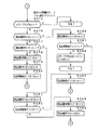
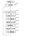
次に、遊技機の動作について説明する。図24および図25は、主基板31における遊技制御用マイクロコンピュータ560が実行するメイン処理を示すフローチャートである。遊技機に対して電源が投入され電力供給が開始されると、リセット信号が入力されるリセット端子の入力レベルがハイレベルになり、遊技制御用マイクロコンピュータ560(具体的には、CPU56)は、プログラムの内容が正当か否か確認するための処理であるセキュリティチェック処理を実行した後、ステップS1以降のメイン処理を開始する。メイン処理において、CPU56は、まず、必要な初期設定を行う。   Next, the operation of the gaming machine will be described. 24 and 25 are flowcharts showing main processing executed by the game control microcomputer 560 on the main board 31. FIG. When power is supplied to the gaming machine and power supply is started, the input level of the reset terminal to which the reset signal is input becomes high level, and the gaming control microcomputer 560 (specifically, the CPU 56) After executing a security check process, which is a process for confirming whether the contents of the program are valid, the main process after step S1 is started. In the main process, the CPU 56 first performs necessary initial settings.

初期設定処理において、CPU56は、まず、割込禁止に設定する(ステップS1)。次に、割込モードを割込モード2に設定し(ステップS2)、スタックポインタにスタックポインタ指定アドレスを設定する(ステップS3)。そして、内蔵デバイスの初期化(内蔵デバイス(内蔵周辺回路)であるCTC(カウンタ/タイマ)およびPIO(パラレル入出力ポート)の初期化など)を行った後(ステップS4)、RAMをアクセス可能状態に設定する(ステップS5)。なお、割込モード2は、CPU56が内蔵する特定レジスタ(Iレジスタ)の値(1バイト)と内蔵デバイスが出力する割込ベクタ(1バイト:最下位ビット0)とから合成されるアドレスが、割込番地を示すモードである。   In the initial setting process, the CPU 56 first sets the interrupt prohibition (step S1). Next, the interrupt mode is set to interrupt mode 2 (step S2), and a stack pointer designation address is set to the stack pointer (step S3). After initialization of the built-in device (CTC (counter / timer) and PIO (parallel input / output port), which are built-in devices (built-in peripheral circuits)) is performed (step S4), the RAM is accessible (Step S5). In the interrupt mode 2, the address synthesized from the value (1 byte) of the specific register (I register) built in the CPU 56 and the interrupt vector (1 byte: least significant bit 0) output from the built-in device is This mode indicates an interrupt address.

次いで、CPU56は、入力ポートを介して入力されるクリアスイッチ(例えば、電源基板に搭載されている。)の出力信号の状態を確認する(ステップS6)。その確認においてオンを検出した場合には、CPU56は、通常の初期化処理を実行する(ステップS10〜S15。S44,S45を含む。)。   Next, the CPU 56 checks the state of the output signal of the clear switch (for example, mounted on the power supply board) input via the input port (step S6). When the ON is detected in the confirmation, the CPU 56 executes a normal initialization process (steps S10 to S15, including S44 and S45).

クリアスイッチがオンの状態でない場合には、遊技機への電力供給が停止したときにバックアップRAM領域のデータ保護処理(例えばパリティデータの付加等の電力供給停止時処理)が行われたか否か確認する(ステップS7)。そのような保護処理が行われていないことを確認したら、CPU56は初期化処理を実行する。バックアップRAM領域にバックアップデータがあるか否かは、例えば、電力供給停止時処理においてバックアップRAM領域に設定されるバックアップフラグの状態によって確認される。   If the clear switch is not on, check whether data protection processing of the backup RAM area (for example, power supply stop processing such as addition of parity data) was performed when power supply to the gaming machine was stopped (Step S7). When it is confirmed that such protection processing is not performed, the CPU 56 executes initialization processing. Whether there is backup data in the backup RAM area is confirmed, for example, by the state of the backup flag set in the backup RAM area in the power supply stop process.

電力供給停止時処理が行われたことを確認したら、CPU56は、バックアップRAM領域のデータチェックを行う(ステップS8)。この実施の形態では、データチェックとしてパリティチェックを行う。よって、ステップS8では、算出したチェックサムと、電力供給停止時処理で同一の処理によって算出され保存されているチェックサムとを比較する。不測の停電等の電力供給停止が生じた後に復旧した場合には、バックアップRAM領域のデータは保存されているはずであるから、チェック結果(比較結果)は正常(一致)になる。チェック結果が正常でないということは、バックアップRAM領域のデータが、電力供給停止時のデータとは異なっていることを意味する。そのような場合には、内部状態を電力供給停止時の状態に戻すことができないので、電力供給の停止からの復旧時でない電源投入時に実行される初期化処理を実行する。   When it is confirmed that the power supply stop process has been performed, the CPU 56 performs data check of the backup RAM area (step S8). In this embodiment, a parity check is performed as a data check. Therefore, in step S8, the calculated checksum is compared with the checksum calculated and stored by the same process in the power supply stop process. When the power supply is stopped after an unexpected power failure or the like, the data in the backup RAM area should be saved, so the check result (comparison result) is normal (matched). That the check result is not normal means that the data in the backup RAM area is different from the data when the power supply is stopped. In such a case, since the internal state cannot be returned to the state when the power supply is stopped, an initialization process that is executed when the power is turned on is not performed when the power supply is stopped.

チェック結果が正常であれば、CPU56は、遊技制御手段の内部状態と演出制御手段等の電気部品制御手段の制御状態を電力供給停止時の状態に戻すための遊技状態復旧処理(ステップS41〜S43の処理)を行う。具体的には、ROM54に格納されているバックアップ時設定テーブルの先頭アドレスをポインタに設定し(ステップS41)、バックアップ時設定テーブルの内容を順次作業領域(RAM55内の領域)に設定する(ステップS42)。作業領域はバックアップ電源によって電源バックアップされている。バックアップ時設定テーブルには、作業領域のうち初期化してもよい領域についての初期化データが設定されている。ステップS41およびS42の処理によって、作業領域のうち初期化してはならない部分については、保存されていた内容がそのまま残る。初期化してはならない部分とは、例えば、電力供給停止前の遊技状態を示すデータ(特別図柄プロセスフラグ、確変フラグ、時短フラグなど)、出力ポートの出力状態が保存されている領域(出力ポートバッファ)、未払出賞球数を示すデータが設定されている部分などである。   If the check result is normal, the CPU 56 recovers the game state restoration process (steps S41 to S43) for returning the internal state of the game control means and the control state of the electrical component control means such as the effect control means to the state when the power supply is stopped. Process). Specifically, the start address of the backup setting table stored in the ROM 54 is set as a pointer (step S41), and the contents of the backup setting table are sequentially set in the work area (area in the RAM 55) (step S42). ). The work area is backed up by a backup power source. In the backup setting table, initialization data for an area that may be initialized in the work area is set. As a result of the processing in steps S41 and S42, the saved contents of the work area that should not be initialized remain as they are. The part that should not be initialized is, for example, data indicating the gaming state before the power supply is stopped (special symbol process flag, probability variation flag, time reduction flag, etc.), and the area where the output state of the output port is saved (output port buffer) ), A portion in which data indicating the number of unpaid prize balls is set.

また、CPU56は、電力供給復旧時の初期化コマンドとしての停電復旧指定コマンドを送信する(ステップS43)。そして、ステップS14Aに移行する。   Further, the CPU 56 transmits a power failure recovery designation command as an initialization command at the time of power supply recovery (step S43). Then, the process proceeds to step S14A.

なお、この実施の形態では、バックアップフラグとチェックデータとの双方を用いてバックアップRAM領域のデータが保存されているか否か確認しているが、いずれか一方のみを用いてもよい。すなわち、バックアップフラグとチェックデータとのいずれかを、遊技状態復旧処理を実行するための契機としてもよい。   In this embodiment, it is confirmed whether the data in the backup RAM area is stored using both the backup flag and the check data. However, only one of them may be used. That is, either the backup flag or the check data may be used as an opportunity for executing the game state restoration process.

初期化処理では、CPU56は、まず、RAMクリア処理を行う(ステップS10)。なお、RAMクリア処理によって、所定のデータ(例えば大当り判定用乱数を生成するためのカウンタのカウント値のデータ)は0に初期化されるが、任意の値またはあらかじめ決められている値に初期化するようにしてもよい。また、RAM55の全領域を初期化せず、所定のデータ(例えば大当り判定用乱数を生成するためのカウンタのカウント値のデータ)をそのままにしてもよい。また、ROM54に格納されている初期化時設定テーブルの先頭アドレスをポインタに設定し(ステップS11)、初期化時設定テーブルの内容を順次作業領域に設定する(ステップS12)。   In the initialization process, the CPU 56 first performs a RAM clear process (step S10). The RAM clear process initializes predetermined data (for example, count value data of a counter for generating a big hit determination random number) to 0, but is initialized to an arbitrary value or a predetermined value. You may make it do. Alternatively, the entire area of the RAM 55 may not be initialized, and predetermined data (for example, count value data of a counter for generating a big hit determination random number) may be left as it is. Further, the start address of the initialization setting table stored in the ROM 54 is set as a pointer (step S11), and the contents of the initialization setting table are sequentially set in the work area (step S12).

ステップS11およびS12の処理によって、例えば、普通図柄判定用乱数カウンタ、普通図柄判定用バッファ、特別図柄バッファ、総賞球数格納バッファ、特別図柄プロセスフラグ、賞球中フラグ、球切れフラグ、払出停止フラグなど制御状態に応じて選択的に処理を行うためのフラグに初期値が設定される。   By the processing of steps S11 and S12, for example, a normal symbol determination random number counter, a normal symbol determination buffer, a special symbol buffer, a total prize ball number storage buffer, a special symbol process flag, an award ball flag, a ball out flag, and a payout stop An initial value is set to a flag such as a flag for selectively performing processing according to the control state.

また、CPU56は、サブ基板(主基板31以外のマイクロコンピュータが搭載された基板。)を初期化するための初期化指定コマンド(遊技制御用マイクロコンピュータ560が初期化処理を実行したことを示すコマンドでもある。)をサブ基板に送信する(ステップS13)。例えば、演出制御用マイクロコンピュータ100は、初期化指定コマンドを受信すると、可変表示装置9において、遊技機の制御の初期化がなされたことを報知するための画面表示、すなわち初期化報知を行う。   Further, the CPU 56 initializes a sub board (a board on which a microcomputer other than the main board 31 is mounted) (a command indicating that the game control microcomputer 560 has executed an initialization process). Is also transmitted to the sub-board (step S13). For example, when the initialization control microcomputer 100 receives the initialization designation command, the variable display device 9 performs screen display for notifying that the control of the gaming machine has been initialized, that is, initialization notification.

さらに、CPU56は、異常報知禁止フラグをセットするとともに(ステップS44)、禁止期間タイマに禁止期間値に相当する値を設定する(ステップS45)。禁止期間値は、後述する異常入賞の報知を禁止する期間を示す値である。また、異常報知禁止フラグは、異常入賞の報知が禁止されていることを示すフラグであり、禁止期間タイマがタイムアウトするまでセット状態に維持される。よって、可変表示装置9において初期化報知が開始されてから所定期間は、異常入賞の報知の開始が禁止される。   Further, the CPU 56 sets an abnormality notification prohibition flag (step S44) and sets a value corresponding to the prohibition period value in the prohibition period timer (step S45). The prohibition period value is a value indicating a period during which an abnormal winning notification described later is prohibited. The abnormality notification prohibition flag is a flag indicating that notification of an abnormal winning is prohibited, and is maintained in the set state until the prohibition period timer times out. Therefore, the start of the abnormal winning notification is prohibited for a predetermined period after the initialization notification is started in the variable display device 9.

なお、遊技制御用マイクロコンピュータ560側で異常入賞の報知を禁止する期間を管理するのではなく、演出制御用マイクロコンピュータ100側で管理するようにしてもよい。この場合、演出制御用マイクロコンピュータ100は、遊技制御用マイクロコンピュータ560から初期化指定コマンドを受信すると、異常報知禁止フラグをセットするとともに、禁止期間タイマに禁止期間値に相当する値を設定する。そして、演出制御用マイクロコンピュータ100は、禁止期間タイマがタイムアウトするまで異常報知禁止フラグをセット状態に維持し、異常入賞の報知を禁止するように制御する。なお、この場合、遊技制御用マイクロコンピュータ560は、ステップS13で初期化指定コマンドを送信すると、ステップS44,S45の処理を実行することなく、そのままステップS14Aに移行するように制御する。   Instead of managing the period during which the abnormal winning notification is prohibited on the game control microcomputer 560 side, it may be managed on the effect control microcomputer 100 side. In this case, when receiving the initialization designation command from the game control microcomputer 560, the production control microcomputer 100 sets the abnormality notification prohibition flag and sets a value corresponding to the prohibition period value in the prohibition period timer. Then, the production control microcomputer 100 maintains the abnormality notification prohibition flag in the set state until the prohibition period timer times out, and performs control so as to prohibit notification of abnormal winning. In this case, when the game control microcomputer 560 transmits the initialization designation command in step S13, the game control microcomputer 560 performs control so that the process directly proceeds to step S14A without executing the processes of steps S44 and S45.

さらに、CPU56は、入力ポート1(図14参照)のデータ(入力データ)を入力し(ステップS14A)、入力データを2バイト目に設定した入力ポートデータ指定コマンド(図30参照)を演出制御基板に送信する(ステップS14B)。なお、遊技機に対する電源供給が開始された直後に、乱数回路503に対してクロック信号が供給されていない異常が生じているときには、入力ポート1のビット5のデータは「0」になっている。また、CPU56は、入力データを、RAM55の領域である入力ポート1バッファに保存する(ステップS14C)。   Further, the CPU 56 inputs data (input data) of the input port 1 (see FIG. 14) (step S14A), and generates an input port data designation command (see FIG. 30) in which the input data is set to the second byte. (Step S14B). It should be noted that immediately after the power supply to the gaming machine is started, when an abnormality occurs in which the clock signal is not supplied to the random number circuit 503, the data of bit 5 of the input port 1 is “0”. . Further, the CPU 56 stores the input data in the input port 1 buffer that is an area of the RAM 55 (step S14C).

なお、メイン処理でステップS14A〜S14Cの処理を実行せずに、後述するタイマ割込処理のみで、入力ポート1のデータを入力し、入力データを2バイト目に設定した入力ポートデータ指定コマンドを演出制御基板に送信するようにしてもよい。   It should be noted that the input port data is input by inputting the data of the input port 1 and the input data is set to the second byte only by the timer interrupt processing described later without executing the processing of steps S14A to S14C in the main processing. You may make it transmit to an effect control board.

そして、ステップS15において、CPU56は、所定時間(例えば2ms)毎に定期的にタイマ割込がかかるように遊技制御用マイクロコンピュータ560に内蔵されているCTCのレジスタの設定を行なう。すなわち、初期値として例えば2msに相当する値が所定のレジスタ(時間定数レジスタ)に設定される。この実施の形態では、2ms毎に定期的にタイマ割込がかかるとする。   In step S15, the CPU 56 sets a register of the CTC built in the game control microcomputer 560 so that a timer interrupt is periodically taken every predetermined time (for example, 2 ms). That is, a value corresponding to, for example, 2 ms is set in a predetermined register (time constant register) as an initial value. In this embodiment, it is assumed that a timer interrupt is periodically taken every 2 ms.

初期化処理の実行(ステップS10〜S15)が完了すると、CPU56は、メイン処理で、表示用乱数更新処理(ステップS17)および初期値用乱数更新処理(ステップS18)を繰り返し実行する。表示用乱数更新処理および初期値用乱数更新処理を実行するときには割込禁止状態に設定し(ステップS16)、表示用乱数更新処理および初期値用乱数更新処理の実行が終了すると割込許可状態に設定する(ステップS19)。この実施の形態では、表示用乱数とは、変動パターンを決定するための乱数であり、表示用乱数更新処理とは、表示用乱数を発生するためのカウンタのカウント値を更新する処理である。また、初期値用乱数更新処理とは、初期値用乱数を発生するためのカウンタのカウント値を更新する処理である。この実施の形態では、初期値用乱数とは、普通図柄に関して当りとするか否か決定するための乱数を発生するためのカウンタ(例えば、特別図柄決定用(大当り種類決定用)乱数発生カウンタや、普通図柄当り判定用乱数発生カウンタ)等の、カウント値の初期値を決定するための乱数である。また、大当りの判定をソフトウェア乱数を用いて行う場合には、初期値用乱数には、大当り判定用乱数発生カウンタのカウント値の初期値を決定するための乱数も含まれる。後述する遊技の進行を制御する遊技制御処理(遊技制御用マイクロコンピュータ560が、遊技機に設けられている可変表示装置、可変入賞球装置、球払出装置等の遊技用の装置を、自身で制御する処理、または他のマイクロコンピュータに制御させるために指令信号を送信する処理、遊技装置制御処理ともいう)において、普通図柄当り判定用乱数のカウント値が1周(普通図柄当り判定用乱数の取りうる値の最小値から最大値までの間の数値の個数分歩進したこと)すると、そのカウンタに初期値が設定される。   When the execution of the initialization process (steps S10 to S15) is completed, the CPU 56 repeatedly executes the display random number update process (step S17) and the initial value random number update process (step S18) in the main process. When executing the display random number update process and the initial value random number update process, the interrupt disabled state is set (step S16). When the display random number update process and the initial value random number update process are finished, the interrupt enabled state is set. Set (step S19). In this embodiment, the display random number is a random number for determining the variation pattern, and the display random number update process is a process for updating the count value of the counter for generating the display random number. The initial value random number update process is a process for updating the count value of the counter for generating the initial value random number. In this embodiment, the initial value random number is a counter for generating a random number for determining whether or not to win a normal symbol (for example, a special symbol determining (big hit type determining) random number generating counter, This is a random number for determining the initial value of the count value, such as a random number generating counter for ordinary symbol determination. When the big hit determination is performed using software random numbers, the initial value random number includes a random number for determining the initial value of the count value of the big hit determination random number generation counter. A game control process for controlling the progress of the game, which will be described later (the game control microcomputer 560 controls game devices such as a variable display device, a variable winning ball device, a ball payout device, etc. provided in the game machine itself. In the process of transmitting a command signal to be controlled by another microcomputer, or a game machine control process), the count value of the random number for determination per normal symbol is one round (the random number for determination per normal symbol is taken). When the value is incremented by the number of values between the minimum value and the maximum value of the possible values), an initial value is set in the counter.

タイマ割込が発生すると、CPU56は、図26に示すステップS20〜S35のタイマ割込処理を実行する。タイマ割込処理において、まず、電源断信号が出力されたか否か(オン状態になったか否か)を検出する電源断検出処理を実行する(ステップS20)。電源断信号は、例えば電源基板に搭載されている電圧低下監視回路が、遊技機に供給される電源の電圧の低下を検出した場合に出力する。そして、電源断検出処理において、CPU56は、電源断信号が出力されたことを検出したら、必要なデータをバックアップRAM領域に保存するための電力供給停止時処理を実行する。次いで、入力ドライバ回路58を介して、ゲートスイッチ32a、第1始動口スイッチ13a、第2始動口スイッチ14a、カウントスイッチ23、および入賞口スイッチ29a,30a,33a,39aの検出信号を入力し、それらの状態判定を行う(スイッチ処理:ステップS21)。   When the timer interrupt occurs, the CPU 56 executes the timer interrupt process in steps S20 to S35 shown in FIG. In the timer interrupt process, first, a power-off detection process for detecting whether or not a power-off signal is output (whether or not an on-state is turned on) is executed (step S20). The power-off signal is output when, for example, a voltage drop monitoring circuit mounted on the power supply board detects a drop in the voltage of the power supplied to the gaming machine. In the power-off detection process, when detecting that the power-off signal has been output, the CPU 56 executes a power supply stop process for saving necessary data in the backup RAM area. Next, detection signals from the gate switch 32a, the first start port switch 13a, the second start port switch 14a, the count switch 23, and the winning port switches 29a, 30a, 33a, and 39a are input via the input driver circuit 58, These state determinations are performed (switch processing: step S21).

次に、CPU56は、特別図柄表示器8、普通図柄表示器10、特別図柄保留記憶表示器18、普通図柄保留記憶表示器41の表示制御を行う表示制御処理を実行する(ステップS22)。特別図柄表示器8および普通図柄表示器10については、ステップS34,S35で設定される出力バッファの内容に応じて各表示器に対して駆動信号を出力する制御を実行する。   Next, the CPU 56 executes display control processing for performing display control of the special symbol display 8, the normal symbol display 10, the special symbol hold storage display 18, and the normal symbol hold storage display 41 (step S22). For the special symbol display 8 and the normal symbol display 10, control for outputting a drive signal to each display is executed according to the contents of the output buffer set in steps S34 and S35.

また、CPU56は、正規の時期以外の時期において大入賞口に遊技球が入賞したことを検出した場合に異常入賞の報知を行わせるための処理を行う(ステップS23:異常入賞報知処理)。   Further, the CPU 56 performs a process for notifying an abnormal winning when it detects that a game ball has won a prize winning opening at a time other than the regular time (step S23: abnormal winning notifying process).

また、CPU56は、入力ポート1(図15参照)の入力データに変化が生じたときに、入力ポート1の入力データを演出制御用マイクロコンピュータ100に送信する入力ポートデータ確認処理を実行する(ステップS23A)。   Further, the CPU 56 executes an input port data confirmation process for transmitting the input data of the input port 1 to the effect control microcomputer 100 when the input data of the input port 1 (see FIG. 15) changes (step). S23A).

次に、遊技制御に用いられる大当り図柄決定用の乱数等の各判定用乱数を生成するための各カウンタのカウント値を更新する処理を行う(判定用乱数更新処理:ステップS24)。CPU56は、さらに、初期値用乱数および表示用乱数を生成するためのカウンタのカウント値を更新する処理を行う(初期値用乱数更新処理,表示用乱数更新処理:ステップS25,S26)。   Next, a process of updating the count value of each counter for generating each random number for determination such as a random number for determining jackpot symbols used for game control is performed (determination random number update process: step S24). The CPU 56 further performs a process of updating the count value of the counter for generating the initial value random number and the display random number (initial value random number update process, display random number update process: steps S25 and S26).

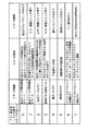
図27は、各乱数を示す説明図である。各乱数は、以下のように使用される。
(1)ランダム1:特別図柄のはずれ図柄(停止図柄)を決定する(はずれ図柄決定用)
(2)ランダム2:大当りを発生させるときの特別図柄の停止図柄を決定する(大当り図柄決定用)
(3)ランダム3:特別図柄の変動パターン(変動時間)を決定する(変動パターン決定用)
(4)ランダム4:普通図柄にもとづく当りを発生させるか否か決定する(普通図柄当り判定用)
(5)ランダム5:ランダム4の初期値を決定する(ランダム4初期値決定用)
FIG. 27 is an explanatory diagram showing each random number. Each random number is used as follows.
(1) Random 1: Decide a special symbol's off symbol (stop symbol) (for determining off symbol)
(2) Random 2: Determines the special symbol stop symbol when generating a big hit (for big hit symbol determination)
(3) Random 3: Determine the variation pattern (variation time) of special symbols (for variation pattern determination)
(4) Random 4: Determines whether or not to generate a hit based on the normal symbol (for normal symbol hit determination)
(5) Random 5: Random 4 initial value is determined (for determining random 4 initial value)

なお、特別図柄通常処理で後述するように、この実施の形態では、乱数回路503から読み出したハードウェア乱数(ランダムR)にもとづいて、大当りとするか否かを判定するとともに、大当りとする場合には大当りの種類(例えば、確変大当りとするか通常大当りとするか)を決定する。そして、図27に示す大当り図柄決定用乱数(ランダム2)にもとづいて、大当り図柄の停止図柄(例えば、奇数図柄のいずれか)が決定される。すなわち、この実施の形態では、まず、ハードウェア乱数であるランダムRにもとづいて、大当りとするか否かと大当りの種類とを一括して決定する。そして、大当りにすると決定すると、ソフトウェア乱数である大当り図柄決定用乱数にもとづいて、特別図柄の停止図柄を決定する。具体的には、後述する特別図柄通常処理において、遊技制御用マイクロコンピュータ560は、ランダムRにもとづいて大当り判定処理を行い、大当りとするか否かを決定するとともに大当りの種類を決定する(ステップS61〜S63参照)。そして、大当りとすると決定すると(ステップS63のY参照)、大当り図柄決定用乱数にもとづいて、特別図柄の停止図柄を決定する(ステップS82,S83参照)。   As will be described later in the special symbol normal processing, in this embodiment, whether or not to make a big hit is determined based on the hardware random number (random R) read from the random number circuit 503. The type of jackpot (for example, whether to be a promiscuous jackpot or a normal jackpot) is determined. Then, based on the jackpot symbol determination random number (random 2) shown in FIG. 27, the stop symbol of the jackpot symbol (for example, one of the odd symbols) is determined. That is, in this embodiment, first, based on the random number R, which is a hardware random number, whether to win or not and the type of jackpot are collectively determined. Then, if it is decided to win, the special symbol stop symbol is determined based on the jackpot symbol determining random number which is a software random number. Specifically, in the special symbol normal process described later, the game control microcomputer 560 performs a jackpot determination process based on the random R, determines whether or not to win and determines the type of jackpot (step (See S61 to S63). Then, if it is determined to be a big hit (see Y in step S63), a special symbol stop symbol is determined based on the big hit symbol determining random number (see steps S82 and S83).

なお、大当りとするか否かと大当りの種類とを、別々の乱数を用いて決定するようにしてもよい。例えば、遊技制御用マイクロコンピュータ560は、まず、ランダムRを用いて大当りとするか否かのみを決定するようにし、次に大当り図柄決定用乱数にもとづいて特別図柄の停止図柄とともに大当りの種類を決定するようにしてもよい。   It should be noted that whether or not to make a jackpot and the type of jackpot may be determined using separate random numbers. For example, the game control microcomputer 560 first determines only whether or not to make a big hit using a random R, and then determines the type of jackpot together with a special symbol stop symbol based on the big hit symbol determining random number. It may be determined.

図26に示された遊技制御処理におけるステップS24では、遊技制御用マイクロコンピュータ560は、(2)の大当り図柄決定用乱数、および(4)の普通図柄当り判定用乱数を生成するためのカウンタのカウントアップ(1加算)を行う。すなわち、それらが判定用乱数であり、それら以外の乱数が表示用乱数または初期値用乱数である。なお、遊技効果を高めるために、上記(1)〜(5)の乱数以外の乱数も用いるようにしてもよい。また、この実施の形態では、大当り判定用乱数は遊技制御用マイクロコンピュータ560に内蔵されたハードウェア(乱数回路)が生成する乱数であるが、大当り判定用乱数として、遊技制御用マイクロコンピュータ560によってプログラムにもとづいて生成されるソフトウェア乱数を用いてもよい。   In step S24 in the game control process shown in FIG. 26, the game control microcomputer 560 uses a counter for generating the jackpot symbol determination random number (2) and the random number for determination per regular symbol (4). Count up (add 1). That is, they are determination random numbers, and other random numbers are display random numbers or initial value random numbers. In addition, in order to improve a game effect, you may make it use random numbers other than the random number of said (1)-(5). In this embodiment, the big hit determination random number is a random number generated by the hardware (random number circuit) built in the game control microcomputer 560. However, the big hit determination random number is generated by the game control microcomputer 560 as the big hit determination random number. Software random numbers generated based on a program may be used.

さらに、CPU56は、特別図柄プロセス処理を行う(ステップS27)。特別図柄プロセス処理では、特別図柄表示器8および大入賞口を所定の順序で制御するための特別図柄プロセスフラグに従って該当する処理を実行する。CPU56は、特別図柄プロセスフラグの値を、遊技状態に応じて更新する。   Further, the CPU 56 performs special symbol process processing (step S27). In the special symbol process, the corresponding symbol is executed in accordance with a special symbol process flag for controlling the special symbol display 8 and the special prize opening in a predetermined order. The CPU 56 updates the value of the special symbol process flag according to the gaming state.

次いで、普通図柄プロセス処理を行う(ステップS28)。普通図柄プロセス処理では、CPU56は、普通図柄表示器10の表示状態を所定の順序で制御するための普通図柄プロセスフラグに従って該当する処理を実行する。CPU56は、普通図柄プロセスフラグの値を、遊技状態に応じて更新する。   Next, normal symbol process processing is performed (step S28). In the normal symbol process, the CPU 56 executes a corresponding process according to the normal symbol process flag for controlling the display state of the normal symbol display 10 in a predetermined order. The CPU 56 updates the value of the normal symbol process flag according to the gaming state.

また、CPU56は、演出制御用マイクロコンピュータ100に演出制御コマンドを送出する処理を行う(演出制御コマンド制御処理:ステップS29)。なお、この実施の形態では、ステップS29において、遊技制御用マイクロコンピュータ560は、演出制御コマンドを構成するMODEデータまたはEXTデータ(送信先のシリアル−パラレル変換IC610〜618のアドレスが付加されたMODEデータまたはEXTデータ)に、ヘッダデータやマークビット、エンドビットを付加して送信制御を行う。そして、演出制御コマンドは、シリアル出力回路78によってシリアルデータに変換され、中継基板77を介して演出制御基板80に送信される。   Further, the CPU 56 performs a process of sending an effect control command to the effect control microcomputer 100 (effect control command control process: step S29). In this embodiment, in step S29, the game control microcomputer 560 causes the MODE data or EXT data (MODE data to which the address of the destination serial-parallel conversion ICs 610 to 618 is added) constituting the effect control command. Alternatively, transmission control is performed by adding header data, mark bits, and end bits to (EXT data). The effect control command is converted into serial data by the serial output circuit 78 and transmitted to the effect control board 80 via the relay board 77.

さらに、CPU56は、例えばホール管理用コンピュータに供給される大当り情報、始動情報、確率変動情報などのデータを出力する情報出力処理を行う(ステップS30)。   Further, the CPU 56 performs information output processing for outputting data such as jackpot information, start information, probability variation information supplied to the hall management computer, for example (step S30).

また、CPU56は、第1始動口スイッチ13a、第2始動口スイッチ14a、カウントスイッチ23および入賞口スイッチ29a,30a,33a,39aの検出信号にもとづく賞球個数の設定などを行う賞球処理を実行する(ステップS31)。具体的には、第1始動口スイッチ13a、第2始動口スイッチ14a、カウントスイッチ23および入賞口スイッチ29a,30a,33a,39aのいずれかがオンしたことにもとづく入賞検出に応じて、払出制御基板37に搭載されている払出制御用マイクロコンピュータに賞球個数を示す払出制御コマンド(賞球個数信号)を出力する。払出制御用マイクロコンピュータは、賞球個数を示す払出制御コマンドに応じて球払出装置97を駆動する。   Further, the CPU 56 performs prize ball processing for setting the number of prize balls based on detection signals from the first start port switch 13a, the second start port switch 14a, the count switch 23, and the winning port switches 29a, 30a, 33a, 39a. Execute (Step S31). Specifically, the payout control is performed in accordance with winning detection based on any one of the first starting port switch 13a, the second starting port switch 14a, the count switch 23, and the winning port switches 29a, 30a, 33a, 39a being turned on. A payout control command (award ball number signal) indicating the number of winning balls is output to a payout control microcomputer mounted on the substrate 37. The payout control microcomputer drives the ball payout device 97 in accordance with a payout control command indicating the number of winning balls.

この実施の形態では、出力ポートの出力状態に対応したRAM領域(出力ポートバッファ)が設けられているのであるが、CPU56は、出力ポートの出力状態に対応したRAM領域におけるソレノイドのオン/オフに関する内容を出力ポートに出力する(ステップS32:出力処理)。   In this embodiment, a RAM area (output port buffer) corresponding to the output state of the output port is provided. However, the CPU 56 relates to on / off of the solenoid in the RAM area corresponding to the output state of the output port. The contents are output to the output port (step S32: output process).

また、CPU56は、特別図柄プロセスフラグの値に応じて特別図柄の演出表示を行うための特別図柄表示制御データを特別図柄表示制御データ設定用の出力バッファに設定する特別図柄表示制御処理を行う(ステップS33)。CPU56は、例えば、特別図柄プロセス処理でセットされる開始フラグがセットされると終了フラグがセットされるまで、変動速度が1コマ/0.2秒であれば、0.2秒が経過する毎に、出力バッファに設定される表示制御データの値を+1する。また、CPU56は、出力バッファに設定された表示制御データに応じて、ステップS22において駆動信号を出力することによって、特別図柄表示器8における特別図柄の可変表示を実行する。   Further, the CPU 56 performs special symbol display control processing for setting special symbol display control data for effect display of the special symbol in the output buffer for setting the special symbol display control data according to the value of the special symbol process flag ( Step S33). For example, if the change speed is 1 frame / 0.2 seconds until the end flag is set when the start flag set in the special symbol process is set, the CPU 56, for example, every 0.2 seconds passes. Then, the value of the display control data set in the output buffer is incremented by one. Further, the CPU 56 performs variable display of the special symbol on the special symbol display 8 by outputting a drive signal in step S22 according to the display control data set in the output buffer.

さらに、CPU56は、普通図柄プロセスフラグの値に応じて普通図柄の演出表示を行うための普通図柄表示制御データを普通図柄表示制御データ設定用の出力バッファに設定する普通図柄表示制御処理を行う(ステップS34)。CPU56は、例えば、普通図柄の変動に関する開始フラグがセットされると終了フラグがセットされるまで、普通図柄の変動速度が0.2秒ごとに表示状態(「○」および「×」)を切り替えるような速度であれば、0.2秒が経過する毎に、出力バッファに設定される表示制御データの値(例えば、「○」を示す1と「×」を示す0)を切り替える。また、CPU56は、出力バッファに設定された表示制御データに応じて、ステップS22において駆動信号を出力することによって、普通図柄表示器10における普通図柄の演出表示を実行する。   Further, the CPU 56 performs a normal symbol display control process for setting normal symbol display control data for effect display of the normal symbol in an output buffer for setting the normal symbol display control data according to the value of the normal symbol process flag ( Step S34). For example, when the start flag related to the variation of the normal symbol is set, the CPU 56 switches the display state (“◯” and “×”) for the variation rate of the normal symbol every 0.2 seconds until the end flag is set. With such a speed, the value of the display control data set in the output buffer (for example, 1 indicating “◯” and 0 indicating “x”) is switched every 0.2 seconds. Further, the CPU 56 outputs a normal signal on the normal symbol display 10 by outputting a drive signal in step S22 according to the display control data set in the output buffer.

その後、割込許可状態に設定し(ステップS35)、処理を終了する。   Thereafter, the interrupt permission state is set (step S35), and the process is terminated.

以上の制御によって、この実施の形態では、遊技制御処理は2ms毎に起動されることになる。なお、遊技制御処理は、タイマ割込処理におけるステップS21〜S34(ステップS30を除く。)の処理に相当する。また、この実施の形態では、タイマ割込処理で遊技制御処理が実行されているが、タイマ割込処理では例えば割込が発生したことを示すフラグのセットのみがなされ、遊技制御処理はメイン処理において実行されるようにしてもよい。   With the above control, in this embodiment, the game control process is started every 2 ms. The game control process corresponds to the processes of steps S21 to S34 (excluding step S30) in the timer interrupt process. In this embodiment, the game control process is executed by the timer interrupt process. However, in the timer interrupt process, for example, only a flag indicating that an interrupt has occurred is set, and the game control process is performed by the main process. May be executed.

図28は、大当り判定テーブルを示す説明図である。大当り判定テーブルとは、ランダムRと比較される大当り判定値が設定されているテーブルである。大当り判定判定テーブルには、通常状態(確変状態でない遊技状態)において用いられる通常時大当り判定テーブル(図28(A)参照)と、確変状態において用いられる確変時大当り判定テーブル(図28(B)参照)とがある。図28(A),(B)の左欄に記載されている数値が大当り判定値である。CPU56は、ランダムRの値がいずれかの大当り判定値と一致すると、大当りとすることに決定する。CPU56は、所定の時期に、乱数回路のカウント値を抽出して抽出値を大当り判定用乱数値とするのであるが、大当り判定用乱数値が図21に示す大当り判定値に一致すると、特別図柄に関して大当り(確変大当りまたは通常大当り)とすることに決定する。   FIG. 28 is an explanatory diagram of a jackpot determination table. The jackpot determination table is a table in which a jackpot determination value to be compared with the random R is set. The jackpot determination determination table includes a normal jackpot determination table (see FIG. 28A) used in a normal state (a gaming state that is not a probability change state) and a probability change jackpot determination table (FIG. 28B) used in a probability change state. See). The numerical values described in the left column of FIGS. 28A and 28B are jackpot determination values. When the value of the random R matches any one of the jackpot determination values, the CPU 56 determines that the jackpot is to be made. The CPU 56 extracts the count value of the random number circuit at a predetermined time and uses the extracted value as the jackpot determination random value. If the jackpot determination random value matches the jackpot determination value shown in FIG. Is determined to be a big hit (probable big hit or normal big hit).

確変大当りとは、大当り遊技後の遊技状態を、通常状態に比べて大当りとすることに決定される確率が高い状態である確変状態に移行させるような大当りである。通常大当りとは、大当り遊技後の遊技状態を確変状態ではない状態に移行させるような大当りである。なお、確変大当りおよび通常大当りの場合には、ラウンド数は、小当りおよび突然確変大当りの場合よりも多く、例えば15ラウンドである。   The probability variation jackpot is a jackpot that shifts the gaming state after the jackpot game to a probability variation state in which there is a high probability of being determined to be a jackpot compared to the normal state. Usually, the big hit is a big hit that shifts the gaming state after the big hit game to a state that is not a probable change state. Note that the number of rounds in the case of a probable big hit and the normal big hit is larger than that in the case of a small hit and a sudden probable big hit, for example, 15 rounds.

小当りとは、大当り遊技状態において大入賞口の開放回数が2回まで許容される当りである。なお、小当り遊技が終了した場合、遊技状態が確変状態に移行することはない。突然確変大当りとは、大当り遊技状態において大入賞口の開放回数が2回まで許容されるが大入賞口の開放時間が極めて短い大当りであり、かつ、大当り遊技後の遊技状態を確変状態に移行させるような大当りである。つまり、この実施の形態では、突然確変大当りと小当りとは、ラウンド数が同じである。   The small win is a hit in which the number of times of opening the big winning opening is allowed in the big hit gaming state. Note that when the small hit game ends, the gaming state does not shift to the probable change state. Suddenly probable jackpot is a jackpot where the number of times the big prize opening is allowed is 2 in the big hit gaming state, but the opening time of the big prize opening is extremely short, and the gaming state after the big hit game is shifted to the probable state It ’s a big hit. That is, in this embodiment, the number of rounds is the same between the sudden probability big hit and the small hit.

なお、突然確変大当りの大当り遊技では、ラウンド数は、通常大当りおよび確変大当りの場合よりも少なく、かつ、各ラウンドの大入賞口開放許容時間(例えば、通常大当りおよび確変大当りの場合の29秒に対して、0.5秒)は通常大当りおよび確変大当りの場合よりも短いが、ラウンド数のみを少なくしたり、大入賞口開放許容時間のみを短くするようにしてもよい。   In the big hit game of sudden probability change big hit, the number of rounds is smaller than in the case of normal big hit and probability variable big hit, and the allowance opening time for each round (for example, 29 seconds in the case of normal big hit and probability variable big hit) On the other hand, 0.5 seconds) is shorter than the case of the normal big hit and the probability variation big hit, but only the number of rounds may be reduced, or only the allowance opening allowance time may be shortened.

なお、大当り判定用乱数(ランダムR)を用いた判定では、大当りとするか否かのみを判定するようにし、大当り図柄決定用乱数(ランダム2)を用いて決定した図柄の種類に応じて大当りの種類(例えば、確変大当りとするか通常大当りとするか)を決定するようにしてもよい。   In the determination using the big hit determination random number (random R), only whether or not the big hit is determined is determined, and the big hit is determined according to the type of the symbol determined using the big hit symbol determination random number (random 2). May be determined (for example, whether it is a probability big hit or a normal big hit).

図29は、この実施の形態で用いられる変動パターンの一例を示す説明図である。後述するように、この実施の形態では、演出制御コマンドは2バイト構成であり、1バイト目はMODE(コマンドの分類)を表し、2バイト目はEXT(コマンドの種類)を表す。図29において、「EXT」とは、2バイト構成の演出制御コマンドにおける2バイト目のEXTデータを示す。また、「変動時間」は特別図柄の変動時間(識別情報の可変表示期間)を示す。   FIG. 29 is an explanatory diagram showing an example of a variation pattern used in this embodiment. As will be described later, in this embodiment, the presentation control command has a 2-byte structure, the first byte represents MODE (command classification), and the second byte represents EXT (command type). In FIG. 29, “EXT” indicates EXT data of the second byte in the effect control command having a two-byte structure. “Variation time” indicates the variation time of the special symbol (variable display period of identification information).

「通常変動」は、リーチ態様を伴わない変動パターンである。「通常変動・短縮」は、リーチ態様を伴わない変動パターンであり、かつ、変動時間が「通常変動」よりも短い変動パターンである。「ノーマルリーチ」は、リーチ態様を伴うが表示結果(停止図柄)が大当り図柄にならない変動パターンである。「リーチA」は、「ノーマルリーチ」とは異なるリーチ態様を持つ変動パターンである。リーチ態様が異なるとは、リーチ変動時間(リーチ演出が行われる期間)で可変表示装置9において異なった態様の変動態様(速度や回転方向等)やキャラクタ画像等が現れたり、可変表示装置9における背景図柄が異なることをいう。例えば、「ノーマルリーチ」では単に1種類の変動態様によってリーチ態様が実現されるのに対して、「リーチA」では、変動速度や変動方向が異なる複数の変動態様を含むリーチ態様が実現される。また、「リーチA・短縮」は、「リーチA」に類似したリーチ態様を持つ変動パターンであるが、リーチ変動時間は、「リーチA」に比べて短い。「リーチA・延長」は、「リーチA」に類似したリーチ態様を持つ変動パターンであるが、リーチ変動時間は、「リーチA」に比べて長い。   “Normal fluctuation” is a fluctuation pattern without a reach mode. “Normal fluctuation / shortening” is a fluctuation pattern without a reach mode and a fluctuation time shorter than “normal fluctuation”. “Normal reach” is a variation pattern that is accompanied by a reach mode but whose display result (stop symbol) does not become a big hit symbol. “Reach A” is a variation pattern having a reach form different from “normal reach”. A different reach mode means that a different mode of change mode (speed, direction of rotation, etc.), a character image, or the like appears in the variable display device 9 in the reach change time (a period in which the reach effect is performed). The background design is different. For example, in “normal reach”, a reach mode is realized by only one type of change mode, whereas in “reach A”, a reach mode including a plurality of change modes having different speeds and directions of change is realized. Further, “reach A / shortening” is a variation pattern having a reach manner similar to “reach A”, but reach variation time is shorter than “reach A”. “Reach A / Extension” is a variation pattern having a reach manner similar to “Reach A”, but the reach variation time is longer than “Reach A”.

「リーチB」は、「ノーマルリーチ」および「リーチA」とは異なるリーチ態様を持つ変動パターンである。また、「リーチB・短縮」は、「リーチB」に類似したリーチ態様を持つ変動パターンであるが、リーチ変動時間は、「リーチB」に比べて短い。「リーチB・延長」は、「リーチB」に類似したリーチ態様を持つ変動パターンであるが、リーチ変動時間は、「リーチB」に比べて長い。「リーチC」は、「ノーマルリーチ」、「リーチA」および「リーチB」とは異なるリーチ態様を持つ変動パターンである。「リーチC・短縮」は、「リーチC」に類似したリーチ態様を持つ変動パターンであるが、リーチ変動時間は、「リーチC」に比べて短い。   “Reach B” is a fluctuation pattern having a reach mode different from “Normal reach” and “Reach A”. Further, “reach B / shortening” is a variation pattern having a reach manner similar to “reach B”, but the reach variation time is shorter than “reach B”. “Reach B / extension” is a variation pattern having a reach manner similar to “reach B”, but reach variation time is longer than “reach B”. “Reach C” is a variation pattern having a reach form different from “normal reach”, “reach A”, and “reach B”. “Reach C / shortening” is a variation pattern having a reach manner similar to “reach C”, but reach variation time is shorter than “reach C”.

また、「スーパーリーチA」は、「ノーマルリーチ」、「リーチA」、「リーチB」および「リーチC」とは異なるリーチ態様を持つ変動パターンであり、例えば動画像によるリーチ態様を持つ変動パターンである。「スーパーリーチB」は、「ノーマルリーチ」、「リーチA」、「リーチB」、「リーチC」および「スーパーリーチA」とは異なるリーチ態様を持つ変動パターンであり、例えば動画像によるリーチ態様を持つ変動パターンである。「リーチA・突確」は、「ノーマルリーチ」、「リーチA」、「リーチB」、「リーチC」、「スーパーリーチA」および「スーパーリーチB」とは異なるリーチ態様を持つ変動パターンである。なお、「リーチA・突確」のリーチ態様は、「リーチA」に類似するリーチ態様である。   “Super reach A” is a variation pattern having a reach mode different from “normal reach”, “reach A”, “reach B”, and “reach C”. is there. “Super reach B” is a variation pattern having a reach form different from “normal reach”, “reach A”, “reach B”, “reach C” and “super reach A”. This is a variation pattern. “Reach A / Accuracy” is a variation pattern having a reach form different from “Normal reach”, “Reach A”, “Reach B”, “Reach C”, “Super reach A” and “Super reach B”. It should be noted that the reach form of “reach A / accuracy” is a reach form similar to “reach A”.

この実施の形態では、通常大当りの場合には、遊技制御用マイクロコンピュータ560は、「リーチA・短縮」、「リーチA」、「リーチB・短縮」、「リーチB」、「リーチC・短縮」、「リーチC」、「スーパーリーチA」または「スーパーリーチB」を選択する。また、確変大当りの場合には、遊技制御用マイクロコンピュータ560は、「リーチA・延長」、「リーチB・延長」、「リーチC・短縮」、「リーチC」、「スーパーリーチA」または「スーパーリーチB」を選択する。突然確変大当りの場合には、「リーチA・突確」を選択する。小当りの場合には、「リーチA・小当り」を選択する。   In this embodiment, in the case of a big hit, the game control microcomputer 560 is “reach A / shortening”, “reach A”, “reach B / shortening”, “reach B”, “reach C / shortening”. ", Reach C", "Super Reach A" or "Super Reach B". Further, in the case of a probable big hit, the game control microcomputer 560 is “reach A / extension”, “reach B / extension”, “reach C / shortening”, “reach C”, “super reach A” or “ Select "Super Reach B". In case of sudden big odds, select “Reach A / Random”. In the case of a small hit, select “reach A / small hit”.

また、図29に示すように、通常大当りの場合にのみ選択される変動パターンと、確変大当りの場合にのみ選択される変動パターンと、通常大当りのときにも確変大当りのときにも選択されうる変動パターンとがある。   Further, as shown in FIG. 29, a variation pattern selected only in the case of a normal big hit, a variation pattern selected only in the case of a probable big hit, and a normal big hit and a probable big hit can be selected. There are fluctuation patterns.

また、時短状態では、「通常変動・短縮」、「リーチA・短縮」、「リーチB・短縮」、および「リーチC・短縮」の変動パターンが選択される。非時短状態では、それ以外の変動パターンが選択される。ただし、「リーチA・突確」の変動パターンは、時短状態でも非時短状態でも使用される。   In the short-time state, the fluctuation patterns of “normal fluctuation / shortening”, “reach A / shortening”, “reach B / shortening”, and “reach C / shortening” are selected. In the non-time-short state, other variation patterns are selected. However, the variation pattern of “reach A / accuracy” is used in both the short-time state and the non-short-time state.

なお、この実施の形態では、大当りが発生し、大当り遊技が終了すると、その後、100回の特別図柄の変動(可変表示)の実行が完了するまで、遊技状態は時短状態になる。また、可変表示が終了すると大当り遊技が開始されるときの特別図柄の可変表示を開始するときに、確変状態にすることに決定された場合には、大当り遊技が終了すると遊技状態が確変状態に移行される。なお、そのときの遊技状態が確変状態であれば、確変状態が継続することになる。   In this embodiment, when a big hit occurs and the big hit game ends, the gaming state becomes a short-time state thereafter until the execution of 100 special symbol changes (variable display) is completed. In addition, when variable display of a special symbol is started when variable display is finished, when it is decided to change to a probable change state when the special symbol variable display is started, the game state is changed into a probable change state when the big hit game is ended. Migrated. If the gaming state at that time is a probability variation state, the probability variation state is continued.

確変状態に移行されたら、その後、100回の特別図柄の変動(可変表示)の実行が完了するまでは、確変状態かつ時短状態である。また、大当り遊技が終了した後の非確変状態において、100回の特別図柄の変動(可変表示)の実行が完了すると遊技状態は通常状態(確変状態でなく、かつ、時短状態でない遊技状態)に移行する。   After the transition to the probability changing state, the state of the probability changing state is short and the state is short until the execution of the variation (variable display) of 100 special symbols is completed. In addition, in the non-probability change state after the big hit game is over, the game state is changed to the normal state (the game state that is not the probability change state and not the short-time state) when the execution of 100 special symbol changes (variable display) is completed. Transition.

次に、遊技制御用マイクロコンピュータ560から演出制御用マイクロコンピュータ100に対する制御コマンドの送出方式について説明する。この実施の形態では、演出制御コマンドは、シリアル出力回路78によってパラレルデータからシリアルデータに変換され、主基板31から中継基板77を介して演出制御基板80に送信される。   Next, a method for sending a control command from the game control microcomputer 560 to the effect control microcomputer 100 will be described. In this embodiment, the effect control command is converted from parallel data to serial data by the serial output circuit 78 and transmitted from the main board 31 to the effect control board 80 via the relay board 77.

この実施の形態では、演出制御コマンドは2バイト構成であり、1バイト目はMODE(コマンドの分類)を表し、2バイト目はEXT(コマンドの種類)を表す。MODEデータの先頭ビット(ビット7)は必ず「1」に設定され、EXTデータの先頭ビット(ビット7)は必ず「0」に設定される。なお、そのようなコマンド形態は一例であって他のコマンド形態を用いてもよい。例えば、1バイトや3バイト以上で構成される制御コマンドを用いてもよい   In this embodiment, the presentation control command has a 2-byte structure, the first byte represents MODE (command classification), and the second byte represents EXT (command type). The first bit (bit 7) of the MODE data is always set to “1”, and the first bit (bit 7) of the EXT data is always set to “0”. Note that such a command form is an example, and other command forms may be used. For example, a control command composed of 1 byte or 3 bytes or more may be used.

図30は、シリアルデータ方式として送信される演出制御コマンドのフォーマットの例を示す説明図である。図30に示すように、演出制御コマンドを送信する際、遊技制御用マイクロコンピュータ560(具体的にはCPU56)は、まず、MODEデータ(アドレスが付加されたMODEデータ)にヘッダデータやマークビット、エンドビットを付加して送信制御を行う。すると、シリアル出力回路78は、ヘッダデータやアドレス、マークビット、エンドビットが付加されたMODEデータをシリアルデータに変換して、中継基板77を介して演出制御基板80に送信する。次いで、遊技制御用マイクロコンピュータ560は、EXTデータ(アドレスが付加されたEXTデータ)にヘッダデータやマークビット、エンドビットを付加して送信制御を行う。すると、シリアル出力回路78は、ヘッダデータやアドレス、マークビット、エンドビットが付加されたEXTデータをシリアルデータに変換して、中継基板77を介して演出制御基板80に送信する。   FIG. 30 is an explanatory diagram showing an example of the format of the effect control command transmitted as the serial data method. As shown in FIG. 30, when transmitting the effect control command, the game control microcomputer 560 (specifically, the CPU 56) first adds header data and mark bits to MODE data (MODE data to which an address is added), Transmission control is performed by adding an end bit. Then, the serial output circuit 78 converts the MODE data to which the header data, the address, the mark bit, and the end bit are added into serial data, and transmits the serial data to the effect control board 80 via the relay board 77. Next, the game control microcomputer 560 performs transmission control by adding header data, mark bits, and end bits to EXT data (EXT data with an address added). Then, the serial output circuit 78 converts the EXT data to which the header data, the address, the mark bit, and the end bit are added into serial data, and transmits the serial data to the effect control board 80 via the relay board 77.

図31は、遊技制御用マイクロコンピュータ560が送信する演出制御コマンドの内容の一例を示す説明図である。図31に示す例において、コマンド8001(H)〜800F(H)は、特別図柄の可変表示に対応して可変表示装置9において可変表示される飾り図柄の変動パターンを指定する演出制御コマンド(変動パターンコマンド)である。なお、変動パターンを指定する演出制御コマンドは、変動開始を指定するためのコマンドでもある。従って、演出制御用マイクロコンピュータ100は、コマンド8001(H)〜800F(H)のいずれかを受信すると、可変表示装置9において飾り図柄の可変表示を開始するように制御する。なお、この実施の形態では、特別図柄の可変表示と飾り図柄の可変表示とは同期(可変表示開始時期および可変表示終了時期が同じ。)しているので、飾り図柄の変動パターン(変動時間)を決定することは、特別図柄の変動パターン(変動時間)を決定することも意味する。   FIG. 31 is an explanatory diagram showing an example of the contents of the effect control command transmitted by the game control microcomputer 560. In the example shown in FIG. 31, commands 8001 (H) to 800F (H) are effect control commands (variation) for designating a variation pattern of decorative symbols that are variably displayed on the variable display device 9 in response to variable display of special symbols. Pattern command). The effect control command for designating the variation pattern is also a command for designating the variation start. Therefore, when the production control microcomputer 100 receives any of the commands 8001 (H) to 800F (H), the variable display device 9 controls the variable display device 9 to start variable display of the decorative symbols. In this embodiment, the variable display of the special symbol and the variable display of the decorative symbol are synchronized (the variable display start time and the variable display end time are the same), so the decorative pattern variation pattern (variation time) Determining also means determining the variation pattern (variation time) of the special symbol.

コマンド8C01(H)〜8C05(H)は、大当りとするか否か、および大当り遊技の種類を示す演出制御コマンドである。演出制御用マイクロコンピュータ100は、コマンド8C01(H)〜8C05(H)の受信に応じて飾り図柄の表示結果を決定するので、コマンド8C01(H)〜8C05(H)を表示結果特定コマンドという。なお、変動パターンコマンドとして、変動パターンを特定可能であるとともに、大当りであるか否かや、確変大当りであるか否か、小当りであるか否かを全て特定可能な演出制御コマンドを送信する場合には、表示結果特定コマンドは送信しないようにしてもよい。そのようにすれば、演出制御用マイクロコンピュータ100に送信する演出制御コマンドのコマンド数を低減することができる。   The commands 8C01 (H) to 8C05 (H) are effect control commands indicating whether or not to make a big hit and the type of the big hit game. The effect control microcomputer 100 determines the display result of the decorative symbols in response to the reception of the commands 8C01 (H) to 8C05 (H). Therefore, the commands 8C01 (H) to 8C05 (H) are referred to as display result specifying commands. As the variation pattern command, a variation control command can be specified, and an effect control command that can identify all of whether it is a big hit, whether it is a probable big hit, or a small hit is transmitted. In this case, the display result specifying command may not be transmitted. By doing so, the number of effect control commands transmitted to the effect control microcomputer 100 can be reduced.

コマンド8F00(H)は、飾り図柄の可変表示(変動)を終了して表示結果(停止図柄)を導出表示することを示す演出制御コマンド(図柄確定指定コマンド)である。演出制御用マイクロコンピュータ100は、図柄確定指定コマンドを受信すると、飾り図柄の可変表示(変動)を終了して表示結果を導出表示する。なお、導出表示とは、図柄を最終的に停止表示させることである。   Command 8F00 (H) is an effect control command (symbol confirmation designation command) indicating that the variable display (fluctuation) of the decorative symbols is terminated and the display result (stop symbol) is derived and displayed. When receiving the symbol confirmation designation command, the effect control microcomputer 100 ends the variable display (fluctuation) of the decorative symbols and derives and displays the display result. The derived display is to finally stop and display the symbol.

コマンド9000(H)は、遊技機に対する電力供給が開始されたときに送信される演出制御コマンド(初期化指定コマンド:電源投入指定コマンド)である。コマンド9200(H)は、遊技機に対する電力供給が再開されたときに送信される演出制御コマンド(停電復旧指定コマンド)である。遊技制御用マイクロコンピュータ560は、遊技機に対する電力供給が開始されたときに、バックアップRAMにデータが保存されている場合には、停電復旧指定コマンドを送信し、そうでない場合には、初期化指定コマンドを送信する。   Command 9000 (H) is an effect control command (initialization designation command: power-on designation command) transmitted when power supply to the gaming machine is started. Command 9200 (H) is an effect control command (power failure recovery designation command) transmitted when power supply to the gaming machine is resumed. When the power supply to the gaming machine is started, the game control microcomputer 560 transmits a power failure recovery designation command if data is stored in the backup RAM, and if not, initialization designation is performed. Send a command.

コマンド9F00(H)は、客待ちデモンストレーションを指定する演出制御コマンド(客待ちデモ指定コマンド)である。   Command 9F00 (H) is an effect control command (customer waiting demonstration designation command) for designating a customer waiting demonstration.

コマンドA001〜A004(H)は、ファンファーレ画面を表示すること、すなわち大当り遊技の開始を指定する演出制御コマンド(大当り開始指定コマンド:ファンファーレ指定コマンド)である。大当り開始指定コマンドには、大当りの種類に応じて、大当り開始1指定〜大当り開始指定4指定コマンドがある。コマンドA1XX(H)は、XXで示す回数目(ラウンド)の大入賞口開放中の表示を示す演出制御コマンド(大入賞口開放中指定コマンド)である。A2XX(H)は、XXで示す回数目(ラウンド)の大入賞口閉鎖を示す演出制御コマンド(大入賞口開放後指定コマンド)である。   The commands A001 to A004 (H) are effect control commands for displaying the fanfare screen, that is, designating the start of the big hit game (big hit start designation command: fanfare designation command). The jackpot start designation commands include jackpot start 1 designation to jackpot start designation 4 designation commands depending on the type of jackpot. The command A1XX (H) is an effect control command (special command during opening of a big winning opening) indicating a display during the opening of the big winning opening for the number of times (round) indicated by XX. A2XX (H) is an effect control command (designation command after opening the big winning opening) indicating the closing of the big winning opening for the number of times (round) indicated by XX.

コマンドA301(H)は、大当り終了画面を表示すること、すなわち大当り遊技の終了を指定するとともに、非確変大当り(通常大当り)であったことを指定する演出制御コマンド(大当り終了1指定コマンド:エンディング1指定コマンド)である。コマンドA302(H)は、大当り終了画面を表示すること、すなわち大当り遊技の終了を指定するとともに、確変大当りであったことを指定する演出制御コマンド(大当り終了2指定コマンド:エンディング2指定コマンド)である。   Command A301 (H) displays a jackpot end screen, that is, specifies the end of the jackpot game, and also specifies an effect control command (special jackpot end 1 designation command: ending) that specifies that the game is a non-probable big hit (usually a big hit) 1 designation command). Command A302 (H) is an effect control command for displaying the jackpot end screen, that is, the end of the jackpot game and specifying that it is a probable big hit (big hit end 2 designation command: ending 2 designation command). is there.

コマンドD001(H)は、異常入賞の報知を指示する演出制御コマンド(異常入賞報知指定コマンド)である。   Command D001 (H) is an effect control command (abnormal winning notification designation command) for instructing notification of abnormal winning.

コマンドFFYY(H)は、入力ポート1の入力データを示す演出制御コマンド(入力ポートデータ指定コマンド)である。YYは、入力ポート1の入力データを示す。   Command FFYY (H) is an effect control command (input port data designation command) indicating input data of input port 1. YY indicates input data of the input port 1.

演出制御基板80に搭載されている演出制御用マイクロコンピュータ100(具体的には、演出制御用CPU101)は、主基板31に搭載されている遊技制御用マイクロコンピュータ560から上述した演出制御コマンドを受信すると、図31に示された内容に応じて可変表示装置9の表示状態を変更したり、ランプの表示状態を変更したり、音声出力基板70に対して音番号データを出力したりする。   The effect control microcomputer 100 (specifically, the effect control CPU 101) mounted on the effect control board 80 receives the above-described effect control command from the game control microcomputer 560 mounted on the main board 31. Then, the display state of the variable display device 9 is changed according to the contents shown in FIG. 31, the display state of the lamp is changed, and the sound number data is output to the audio output board 70.

図32は、演出制御コマンドの送信タイミングの一例を示す説明図である。図32に示すように、遊技制御用マイクロコンピュータ560は、変動開始時に、変動パターンコマンドおよび表示結果特定コマンドを送信する。そして、可変表示時間が経過すると、図柄確定指定コマンドを送信する。   FIG. 32 is an explanatory diagram illustrating an example of the transmission timing of the effect control command. As shown in FIG. 32, the game control microcomputer 560 transmits a change pattern command and a display result specifying command at the start of change. When the variable display time has elapsed, a symbol confirmation designation command is transmitted.

なお、変動パターンコマンドを送信する前に、遊技状態(例えば、通常状態/時短状態/確変状態)に応じた可変表示装置9における背景画像を指定する背景指定コマンドを送信するようにしてもよい。また、表示結果特定コマンドに続いて保留記憶数を示す演出制御コマンドを送信するようにしてもよい。   Before transmitting the variation pattern command, a background designation command for designating a background image in the variable display device 9 according to the gaming state (for example, normal state / short time state / probability variation state) may be transmitted. Further, an effect control command indicating the number of reserved memories may be transmitted following the display result specifying command.

図33は、コマンドFFYY(H)(入力ポートデータ指定コマンド)のEXTデータ(YYの部分)の構成を示す説明図である。EXTデータのビット割り当ては、図15に示された入力ポート1のビット割り当てと同じである。すなわち、ビット5(D5)には、乱数エラー信号に対応する乱数エラー指定ビットが割り当てられている。ビット4(D4)には、ドア開閉信号に対応するドア開放エラー指定ビットが割り当てられている。ビット3(D3)には、払出エラー信号に対応する払出エラー指定ビットが割り当てられている。ビット2(D2)には、球切れエラー信号に対応する球切れエラー指定ビットが割り当てられている。ビット1(D1)には、満タンエラー信号に対応する満タンエラー指定ビットが割り当てられている。そして、ビット0(D0)には、賞球カウント信号に対応する賞球カウント指定ビットが割り当てられている。なお、図33に示す例では、入力ポートデータ指定コマンドのEXTデータのビット6,7は未使用であるから、それらのビットを、遊技制御用マイクロコンピュータ560が判定したエラーを示す情報(例えば、大入賞口への異常入賞が生じたか否か判定するように構成されている場合には、異常入賞の発生、すなわち大入賞口を開放する制御を行っていないにもかかわらずカウントスイッチ23の検出信号がオン状態になったことを示す情報)を演出制御用マイクロコンピュータ100に送信する場合に使用することができる。   FIG. 33 is an explanatory diagram showing a configuration of EXT data (YY portion) of the command FFYY (H) (input port data designation command). The bit assignment of the EXT data is the same as the bit assignment of the input port 1 shown in FIG. That is, a random number error designation bit corresponding to the random number error signal is assigned to bit 5 (D5). Bit 4 (D4) is assigned a door opening error designation bit corresponding to the door opening / closing signal. A payout error designation bit corresponding to the payout error signal is assigned to bit 3 (D3). Bit 2 (D2) is assigned a ball-out error designation bit corresponding to the ball-out error signal. Bit 1 (D1) is assigned a full tank error designation bit corresponding to the full tank error signal. A prize ball count designation bit corresponding to the prize ball count signal is assigned to bit 0 (D0). In the example shown in FIG. 33, since bits 6 and 7 of the EXT data of the input port data designation command are unused, the bits indicate information indicating an error determined by the game control microcomputer 560 (for example, In the case where it is configured to determine whether or not an abnormal winning at the big winning opening has occurred, the detection of the count switch 23 even though the occurrence of the abnormal winning, that is, the control for opening the big winning opening is not performed. This information can be used when transmitting information indicating that the signal is turned on) to the production control microcomputer 100.

なお、入力ポート1の全てのビット状態をそのまま入力ポートデータ指定コマンドとして送信するのではなく、いずれかのエラーが発生したときに、そのエラー状態を付加して入力ポートデータ指定コマンドを送信するようにしてもよい。例えば、乱数回路エラーが発生したか否かを判定し、発生していれば、乱数回路エラーに対応するビット(ビットD5)に値を付加して入力ポートデータ指定コマンドを送信してもよい。   Note that not all bit states of the input port 1 are transmitted as input port data designation commands as they are, but when any error occurs, the error state is added and the input port data designation command is transmitted. It may be. For example, it is determined whether or not a random circuit error has occurred. If it has occurred, an input port data designation command may be transmitted with a value added to the bit (bit D5) corresponding to the random circuit error.

なお、賞球カウント信号を、遊技制御用マイクロコンピュータ560に入力することなく、そのまま主基板31を介して(すなわち、主基板31をスルーして)、情報端子盤34に入力するように構成してもよい。さらに、賞球カウント信号を、払出制御用マイクロコンピュータ370にも入力することなく、そのまま主基板31および払出制御基板37を介して(すなわち、主基板31および払出制御基板37の両方をスルーして)、情報端子盤34に入力するように構成してもよい。また、賞球カウント信号を、払出制御用マイクロコンピュータ370に一旦入力したあとに、さらに遊技制御用マイクロコンピュータ560に入力するようにし、遊技制御用マイクロコンピュータ560を介して情報端子盤34に入力するようにしてもよい。また、賞球カウント信号を演出制御基板80には入力しないように構成してもよい。   The prize ball count signal is input to the information terminal board 34 as it is through the main board 31 (that is, through the main board 31) without being input to the game control microcomputer 560. May be. Further, the prize ball count signal is not input to the payout control microcomputer 370, and is directly passed through the main board 31 and the payout control board 37 (that is, through both the main board 31 and the payout control board 37). ), It may be configured to input to the information terminal board 34. The prize ball count signal is once input to the payout control microcomputer 370 and then input to the game control microcomputer 560 and then input to the information terminal board 34 via the game control microcomputer 560. You may do it. Further, the prize ball count signal may not be input to the effect control board 80.

なお、満タンエラー信号を、遊技制御用マイクロコンピュータ560に入力することなく、そのまま主基板31を介して(すなわち、主基板31をスルーして)、情報端子盤34に入力するように構成してもよい。さらに、満タンエラー信号を、払出制御用マイクロコンピュータ370にも入力することなく、そのまま主基板31および払出制御基板37を介して(すなわち、主基板31および払出制御基板37の両方をスルーして)、情報端子盤34に入力するように構成してもよい。また、満タンエラー信号を、払出制御用マイクロコンピュータ370に一旦入力したあとに、さらに遊技制御用マイクロコンピュータ560に入力するようにし、遊技制御用マイクロコンピュータ560を介して情報端子盤34に入力するようにしてもよい。また、満タンエラー信号を演出制御基板80には入力しないように構成してもよい。   The full error signal is inputted to the information terminal board 34 as it is through the main board 31 (that is, through the main board 31) without being inputted to the game control microcomputer 560. Also good. Further, the full tank error signal is not input to the payout control microcomputer 370, but directly through the main board 31 and the payout control board 37 (that is, through both the main board 31 and the payout control board 37). The information terminal board 34 may be configured to input. In addition, the full tank error signal is once input to the payout control microcomputer 370 and then input to the game control microcomputer 560, and is input to the information terminal board 34 via the game control microcomputer 560. It may be. Further, the full error signal may not be input to the effect control board 80.

なお、球切れエラー信号を、遊技制御用マイクロコンピュータ560に入力することなく、そのまま主基板31を介して(すなわち、主基板31をスルーして)、情報端子盤34に入力するように構成してもよい。さらに、球切れエラー信号を、払出制御用マイクロコンピュータ370にも入力することなく、そのまま主基板31および払出制御基板37を介して(すなわち、主基板31および払出制御基板37の両方をスルーして)、情報端子盤34に入力するように構成してもよい。また、球切れエラー信号を、払出制御用マイクロコンピュータ370に一旦入力したあとに、さらに遊技制御用マイクロコンピュータ560に入力するようにし、遊技制御用マイクロコンピュータ560を介して情報端子盤34に入力するようにしてもよい。また、球切れエラー信号を演出制御基板80には入力しないように構成してもよい。   The ball break error signal is inputted to the information terminal board 34 as it is through the main board 31 (that is, through the main board 31) without being inputted to the game control microcomputer 560. May be. Further, the ball break error signal is not input to the payout control microcomputer 370 without passing through the main board 31 and the payout control board 37 (that is, through both the main board 31 and the payout control board 37). ), It may be configured to input to the information terminal board 34. In addition, after the ball break error signal is once input to the payout control microcomputer 370, it is further input to the game control microcomputer 560 and is input to the information terminal board 34 via the game control microcomputer 560. You may do it. Further, it may be configured not to input the ball break error signal to the effect control board 80.

なお、払出エラー信号を、遊技制御用マイクロコンピュータ560に入力することなく、そのまま主基板31を介して(すなわち、主基板31をスルーして)、情報端子盤34に入力するように構成してもよい。また、払出エラー信号を、払出制御用マイクロコンピュータ370からさらに遊技制御用マイクロコンピュータ560に入力するようにし、遊技制御用マイクロコンピュータ560を介して情報端子盤34に入力するようにしてもよい。また、払出エラー信号を演出制御基板80には入力しないように構成してもよい。   The payout error signal is inputted to the information terminal board 34 as it is through the main board 31 (that is, through the main board 31) without being inputted to the game control microcomputer 560. Also good. Further, the payout error signal may be further input from the payout control microcomputer 370 to the game control microcomputer 560 and input to the information terminal board 34 via the game control microcomputer 560. Further, the payout error signal may not be input to the effect control board 80.

なお、ドア開閉信号を、遊技制御用マイクロコンピュータ560に入力することなく、そのまま主基板31を介して(すなわち、主基板31をスルーして)、情報端子盤34に入力するように構成してもよい。さらに、ドア開閉信号を、払出制御用マイクロコンピュータ370にも入力することなく、そのまま主基板31および払出制御基板37を介して(すなわち、主基板31および払出制御基板37の両方をスルーして)、情報端子盤34に入力するように構成してもよい。また、ドア開閉信号を、払出制御用マイクロコンピュータ370に一旦入力したあとに、さらに遊技制御用マイクロコンピュータ560に入力するようにし、遊技制御用マイクロコンピュータ560を介して情報端子盤34に入力するようにしてもよい。また、ドア開閉信号を演出制御基板80には入力しないように構成してもよい。   The door opening / closing signal is input to the information terminal board 34 as it is through the main board 31 (that is, through the main board 31) without being input to the game control microcomputer 560. Also good. Further, the door opening / closing signal is not input to the payout control microcomputer 370, but directly through the main board 31 and the payout control board 37 (that is, through both the main board 31 and the payout control board 37). The information terminal board 34 may be configured to input. In addition, the door opening / closing signal is once input to the payout control microcomputer 370 and then input to the game control microcomputer 560, and is input to the information terminal board 34 via the game control microcomputer 560. It may be. Further, the door opening / closing signal may not be input to the effect control board 80.

なお、乱数エラー信号を、遊技制御用マイクロコンピュータ560に入力することなく、そのまま主基板31を介して(すなわち、主基板31をスルーして)、情報端子盤34に入力するように構成してもよい。さらに、乱数エラー信号を、払出制御用マイクロコンピュータ370にも入力することなく、そのまま主基板31および払出制御基板37を介して(すなわち、主基板31および払出制御基板37の両方をスルーして)、情報端子盤34に入力するように構成してもよい。また、乱数エラー信号を演出制御基板80には入力しないように構成してもよい。   The random number error signal is input to the information terminal board 34 as it is through the main board 31 (that is, through the main board 31) without being input to the game control microcomputer 560. Also good. Further, the random number error signal is not input to the payout control microcomputer 370, but directly through the main board 31 and the payout control board 37 (that is, through both the main board 31 and the payout control board 37). The information terminal board 34 may be configured to input. Further, the random number error signal may not be input to the effect control board 80.

図34および図35は、主基板31に搭載される遊技制御用マイクロコンピュータ560(具体的には、CPU56)が実行する特別図柄プロセス処理(ステップS27)のプログラムの一例を示すフローチャートである。上述したように、特別図柄プロセス処理では特別図柄表示器8および大入賞口を制御するための処理が実行される。特別図柄プロセス処理において、CPU56は、始動入賞口13に遊技球が入賞したことを検出するための第1始動口スイッチ13aまたは第2始動口スイッチ14aがオンしていたら、すなわち始動入賞が発生していたら、始動口スイッチ通過処理を実行する(ステップS311,S312)。そして、ステップS300〜S310のうちのいずれかの処理を行う。   FIG. 34 and FIG. 35 are flowcharts showing an example of a special symbol process process (step S27) program executed by the game control microcomputer 560 (specifically, the CPU 56) mounted on the main board 31. As described above, in the special symbol process, a process for controlling the special symbol display 8 and the special winning opening is executed. In the special symbol process, if the first start port switch 13a or the second start port switch 14a for detecting that a game ball has won the start winning port 13 is turned on, that is, a start winning is generated. If so, start port switch passage processing is executed (steps S311 and S312). Then, any one of steps S300 to S310 is performed.

ステップS300〜S310の処理は、以下のような処理である。   The processes in steps S300 to S310 are as follows.

特別図柄通常処理(ステップS300):特別図柄プロセスフラグの値が0であるときに実行される。遊技制御用マイクロコンピュータ560は、特別図柄の可変表示が開始できる状態になると、保留記憶数(始動入賞記憶数)を確認する。保留記憶数は保留記憶数カウンタのカウント値により確認できる。保留記憶数が0でない場合には、大当りとするか否か決定する。そして、内部状態(特別図柄プロセスフラグ)をステップS301に対応した値(この例では1)に更新する。   Special symbol normal processing (step S300): Executed when the value of the special symbol process flag is zero. When the game control microcomputer 560 is ready to start the variable display of the special symbol, it checks the number of reserved memories (the number of start winning memories). The reserved memory number can be confirmed by the count value of the reserved memory number counter. If the number of reserved memories is not 0, it is determined whether or not to win. Then, the internal state (special symbol process flag) is updated to a value (1 in this example) corresponding to step S301.

変動パターン設定処理(ステップS301):特別図柄プロセスフラグの値が1であるときに実行される。特別図柄の可変表示後の停止図柄を決定する。また、変動パターンを決定し、その変動パターンにおける変動時間(可変表示時間:可変表示を開始してから表示結果が導出表示(停止表示)するまでの時間)を特別図柄の可変表示の変動時間とすることに決定する。また、特別図柄の変動時間を計測する変動時間タイマをスタートさせる。そして、内部状態(特別図柄プロセスフラグ)をステップS302に対応した値(この例では2)に更新する。   Fluctuation pattern setting process (step S301): This process is executed when the value of the special symbol process flag is 1. The stop symbol after the variable display of the special symbol is determined. Also, the variation pattern is determined, and the variation time in the variation pattern (variable display time: the time from the start of variable display until the display result is derived and displayed (stop display)) Decide to do. Also, a variable time timer for measuring the special symbol variable time is started. Then, the internal state (special symbol process flag) is updated to a value (2 in this example) corresponding to step S302.

表示結果特定コマンド送信処理(ステップS302):特別図柄プロセスフラグの値が2であるときに実行される。演出制御用マイクロコンピュータ100に、表示結果特定コマンドを送信する制御を行う。そして、内部状態(特別図柄プロセスフラグ)をステップS303に対応した値(この例では3)に更新する。   Display result specifying command transmission process (step S302): executed when the value of the special symbol process flag is 2. Control for transmitting a display result specifying command to the production control microcomputer 100 is performed. Then, the internal state (special symbol process flag) is updated to a value (3 in this example) corresponding to step S303.

特別図柄変動中処理(ステップS303):特別図柄プロセスフラグの値が3であるときに実行される。変動パターン設定処理で選択された変動パターンの変動時間が経過(ステップS301でセットされる変動時間タイマがタイムアウトすなわち変動時間タイマの値が0になる)すると、内部状態(特別図柄プロセスフラグ)をステップS304に対応した値(この例では4)に更新する。   Special symbol changing process (step S303): This process is executed when the value of the special symbol process flag is 3. When the variation time of the variation pattern selected in the variation pattern setting process elapses (the variation time timer set in step S301 times out, that is, the variation time timer value becomes 0), the internal state (special symbol process flag) is stepped. Update to a value corresponding to S304 (4 in this example).

特別図柄停止処理(ステップS304):特別図柄プロセスフラグの値が4であるときに実行される。特別図柄表示器8における可変表示を停止して停止図柄を導出表示させる。また、演出制御用マイクロコンピュータ100に、図柄確定指定コマンドを送信する制御を行う。そして、大当りフラグがセットされ、かつ、小当りフラグがセットされていない場合には、内部状態(特別図柄プロセスフラグ)をステップS305に対応した値(この例では5)に更新する。小当りフラグがセットされている場合には、内部状態(特別図柄プロセスフラグ)をステップS308に対応した値(この例では8)に更新する。大当りフラグがセットされていない場合には、内部状態(特別図柄プロセスフラグ)をステップS300に対応した値(この例では0)に更新する。なお、演出制御用マイクロコンピュータ100は、遊技制御用マイクロコンピュータ560が送信する図柄確定指定コマンドを受信すると可変表示装置9において飾り図柄が停止されるように制御する。   Special symbol stop process (step S304): executed when the value of the special symbol process flag is 4. The variable display on the special symbol display 8 is stopped and the stop symbol is derived and displayed. In addition, control for transmitting a symbol confirmation designation command to the effect control microcomputer 100 is performed. When the big hit flag is set and the small hit flag is not set, the internal state (special symbol process flag) is updated to a value (5 in this example) corresponding to step S305. If the small hit flag is set, the internal state (special symbol process flag) is updated to a value (8 in this example) corresponding to step S308. If the big hit flag is not set, the internal state (special symbol process flag) is updated to a value corresponding to step S300 (0 in this example). The effect control microcomputer 100 controls the variable display device 9 to stop the decorative symbols when it receives the symbol confirmation designation command transmitted by the game control microcomputer 560.

大入賞口開放前処理(ステップS305):特別図柄プロセスフラグの値が5であるときに実行される。大入賞口開放前処理では、大入賞口を開放する制御を行う。具体的には、カウンタ(例えば大入賞口に入った遊技球数をカウントするカウンタ)などを初期化するとともに、ソレノイド21を駆動して大入賞口を開放状態にする。また、タイマによって大入賞口開放中処理の実行時間を設定し、内部状態(特別図柄プロセスフラグ)をステップS306に対応した値(この例では6)に更新する。なお、大入賞口開放前処理は各ラウンド毎に実行されるが、第1ラウンドを開始する場合には、大入賞口開放前処理は大当り遊技を開始する処理でもある。   Preliminary winning opening opening process (step S305): This is executed when the value of the special symbol process flag is 5. In the pre-opening process for the big prize opening, control for opening the big prize opening is performed. Specifically, a counter (for example, a counter that counts the number of game balls that have entered the big prize opening) is initialized, and the solenoid 21 is driven to open the big prize opening. Also, the execution time of the special prize opening opening process is set by the timer, and the internal state (special symbol process flag) is updated to a value corresponding to step S306 (6 in this example). The pre-opening process for the big winning opening is executed for each round, but when the first round is started, the pre-opening process for the big winning opening is also a process for starting the big hit game.

大入賞口開放中処理(ステップS306):特別図柄プロセスフラグの値が6であるときに実行される。大当り遊技状態中のラウンド表示の演出制御コマンドを演出制御用マイクロコンピュータ100に送信する制御や大入賞口の閉成条件の成立を確認する処理等を行う。大入賞口の閉成条件が成立し、かつ、まだ残りラウンドがある場合には、内部状態(特別図柄プロセスフラグ)をステップS305に対応した値(この例では5)に更新する。また、全てのラウンドを終えた場合には、内部状態(特別図柄プロセスフラグ)をステップS307に対応した値(この例では7)に更新する。   Large winning opening opening process (step S306): This process is executed when the value of the special symbol process flag is 6. A control for transmitting an effect control command for round display during the big hit gaming state to the effect control microcomputer 100, a process for confirming the completion of the closing condition of the big prize opening, and the like are performed. If the closing condition for the special prize opening is satisfied and there are still remaining rounds, the internal state (special symbol process flag) is updated to a value (5 in this example) corresponding to step S305. When all the rounds are completed, the internal state (special symbol process flag) is updated to a value corresponding to step S307 (7 in this example).

大当り終了処理(ステップS307):特別図柄プロセスフラグの値が7であるときに実行される。大当り遊技状態が終了したことを遊技者に報知する表示制御を演出制御用マイクロコンピュータ100に行わせるための制御を行う。また、遊技状態を示すフラグ(例えば、確変フラグ)をセットする処理を行う。そして、内部状態(特別図柄プロセスフラグ)をステップS300に対応した値(この例では0)に更新する。   Big hit end process (step S307): executed when the value of the special symbol process flag is 7. Control is performed to cause the microcomputer 100 for effect control to perform display control for notifying the player that the big hit gaming state has ended. Further, a process for setting a flag (for example, a probability variation flag) indicating a gaming state is performed. Then, the internal state (special symbol process flag) is updated to a value (0 in this example) corresponding to step S300.

小当り開放前処理(ステップS308):特別図柄プロセスフラグの値が8であるときに実行される。小当り開放前処理では、大入賞口を開放する制御を行う。具体的には、カウンタ(例えば大入賞口に入った遊技球数をカウントするカウンタ)などを初期化するとともに、ソレノイド21を駆動して大入賞口を開放状態にする。また、タイマによって大入賞口開放中処理の実行時間を設定し、内部状態(特別図柄プロセスフラグ)をステップS309に対応した値(この例では9)に更新する。なお、小当り開放前処理は小当りにおいて大入賞口を開放する毎に実行されるが、1回目に大入賞口の開放を開始する場合には、小当り開放前処理は小当り遊技を開始する処理でもある。   Small hit release pre-processing (step S308): This process is executed when the value of the special symbol process flag is 8. In the pre-opening process for small hits, control is performed to open the big prize opening. Specifically, a counter (for example, a counter that counts the number of game balls that have entered the big prize opening) is initialized, and the solenoid 21 is driven to open the big prize opening. Also, the execution time of the special prize opening opening process is set by the timer, and the internal state (special symbol process flag) is updated to a value corresponding to step S309 (9 in this example). Note that the pre-opening process for small hits is executed each time the big winning opening is opened in the small hits, but if the big winning opening is opened for the first time, the pre-opening for small hits starts the small hit game. It is also a process to do.

小当り開放中処理(ステップS309):特別図柄プロセスフラグの値が9であるときに実行される。小当り遊技状態中の大入賞口の開放回表示(大当りのラウンド表示に相当する)の演出制御コマンドを演出制御用マイクロコンピュータ100に送信する制御や大入賞口の閉成条件の成立を確認する処理等を行う。大入賞口の閉成条件が成立し、かつ、まだ大入賞口の開放回数が残っている場合には、内部状態(特別図柄プロセスフラグ)をステップS308に対応した値(この例では8)に更新する。また、全ての開放回数(例えば2回)の大入賞口の開放を終えた場合には、内部状態(特別図柄プロセスフラグ)をステップS310に対応した値(この例では10(10進数))に更新する。   Small hit release processing (step S309): executed when the value of the special symbol process flag is 9. Control for transmitting the presentation control command of the opening of the big winning opening (corresponding to the big winning round display) during the small hit gaming state to the microcomputer 100 for the production control and confirmation of the closing condition of the big winning opening are confirmed. Perform processing. When the closing condition of the big prize opening is satisfied and the number of opening of the big prize opening still remains, the internal state (special symbol process flag) is set to a value (8 in this example) corresponding to step S308. Update. In addition, when all the opening times (for example, two times) are finished, the internal state (special symbol process flag) is set to a value corresponding to step S310 (in this example, 10 (decimal number)). Update.

小当り終了処理(ステップS310):特別図柄プロセスフラグの値が10であるときに実行される。小当り遊技状態が終了したことを遊技者に報知する表示制御を演出制御用マイクロコンピュータ100に行わせるための制御を行う。そして、内部状態(特別図柄プロセスフラグ)をステップS300に対応した値(この例では0)に更新する。   Small hit end process (step S310): executed when the value of the special symbol process flag is 10. Control is performed to cause the microcomputer 100 for effect control to perform display control for notifying the player that the small hit gaming state has ended. Then, the internal state (special symbol process flag) is updated to a value (0 in this example) corresponding to step S300.

図36は、ステップS312の始動口スイッチ通過処理を示すフローチャートである。始動口スイッチ通過処理において、CPU56は、保留記憶数が上限値である4になっているか否か確認する(ステップS211)。保留記憶数が4になっている場合には、処理を終了する。   FIG. 36 is a flowchart showing the start-port switch passing process in step S312. In the start port switch passing process, the CPU 56 checks whether or not the reserved storage number is 4 which is the upper limit value (step S211). If the number of reserved memories is 4, the process is terminated.

保留記憶数が4になっていない場合には、保留記憶数を示す保留記憶数カウンタの値を1増やす(ステップS212)。また、CPU56は、ソフトウェア乱数(大当り図柄決定用乱数等を生成するためのカウンタの値等)およびランダムR(大当り判定用乱数)を抽出し、それらを、抽出した乱数値として保留記憶数カウンタの値に対応する保留記憶バッファにおける保存領域に格納する処理を実行する(ステップS213)。ステップS213では、CPU56は、ソフトウェア乱数としてランダム1〜3(図27参照)の値を抽出し、乱数回路のカウント値を読み出すことによってランダムRを抽出する。また、保留記憶バッファにおいて、保存領域は、保留記憶数の上限値と同数確保されている。また、大当り図柄決定用乱数等を生成するためのカウンタや保留記憶バッファは、RAM55に形成されている。「RAMに形成されている」とは、RAM内の領域であることを意味する。   If the number of reserved memories is not 4, the value of the reserved memory number counter indicating the number of reserved memories is incremented by 1 (step S212). Further, the CPU 56 extracts software random numbers (counter value for generating a big hit symbol determination random number, etc.) and random R (big hit determination random number), and uses them as an extracted random number value of the reserved memory number counter. A process of storing in the storage area in the storage buffer corresponding to the value is executed (step S213). In step S213, the CPU 56 extracts random values 1 to 3 (see FIG. 27) as software random numbers, and extracts the random R by reading the count value of the random number circuit. In the reserved storage buffer, the same number of storage areas as the upper limit value of the number of reserved memories is secured. Further, a counter for generating a jackpot symbol determination random number and the like and a reserved storage buffer are formed in the RAM 55. “Formed in RAM” means an area in the RAM.

図37および図38は、特別図柄プロセス処理における特別図柄通常処理(ステップS300)を示すフローチャートである。特別図柄通常処理において、CPU56は、保留記憶数の値を確認する(ステップS51)。具体的には、保留記憶数カウンタのカウント値を確認する。保留記憶数が0であれば処理を終了する。   37 and 38 are flowcharts showing the special symbol normal process (step S300) in the special symbol process. In the special symbol normal process, the CPU 56 checks the value of the number of reserved storage (step S51). Specifically, the count value of the pending storage number counter is confirmed. If the number of reserved memories is 0, the process is terminated.

保留記憶数が0でなければ、CPU56は、RAM55の保留記憶数バッファにおける保留記憶数=1に対応する保存領域に格納されている各乱数値を読み出してRAM55の乱数バッファ領域に格納する(ステップS52)。そして、保留記憶数の値を1減らし(保留記憶数カウンタのカウント値を1減算し)、かつ、各保存領域の内容をシフトする(ステップS53)。すなわち、RAM55の保留記憶数バッファにおいて保留記憶数=n(n=2,3,4)に対応する保存領域に格納されている各乱数値を、保留記憶数=n−1に対応する保存領域に格納する。よって、各保留記憶数に対応するそれぞれの保存領域に格納されている各乱数値が抽出された順番は、常に、保留記憶数=1,2,3,4の順番と一致するようになっている。   If the reserved memory number is not 0, the CPU 56 reads each random number value stored in the storage area corresponding to the reserved memory number = 1 in the reserved memory number buffer of the RAM 55 and stores it in the random number buffer area of the RAM 55 (step S52). Then, the value of the reserved memory number is reduced by 1 (the count value of the reserved memory number counter is decremented by 1), and the contents of each storage area are shifted (step S53). That is, each random number value stored in the storage area corresponding to the reserved memory number = n (n = 2, 3, 4) in the reserved memory number buffer of the RAM 55 is stored in the storage area corresponding to the reserved memory number = n−1. To store. Therefore, the order in which the random number values stored in the respective storage areas corresponding to the number of reserved memories is extracted always matches the order of the number of reserved memories = 1, 2, 3 and 4. Yes.

そして、CPU56は、乱数バッファ領域からランダムR(大当り判定用乱数)を読み出し(ステップS61)、大当り判定モジュールを実行する(ステップS62)。大当り判定モジュールは、あらかじめ決められている大当り判定値(図28参照)と大当り判定用乱数とを比較し、それらが一致したら大当り(通常大当り、確変大当りまたは突然確変大当り)または小当りとすることに決定する処理を実行するプログラムである。   Then, the CPU 56 reads a random R (a jackpot determination random number) from the random number buffer area (step S61), and executes a jackpot determination module (step S62). The big hit judgment module compares the big hit judgment value (see Fig. 28) determined in advance with the big hit judgment random number, and if they match, the big hit (normal big hit, probability variation big hit or sudden probability variation big hit) or small hit This is a program for executing the process to be determined.

なお、CPU56は、遊技状態が確変状態であるときには、図28(B)に示すような大当り判定値が設定されているテーブルにおける大当り判定値を使用し、遊技状態が通常状態(非確変状態)であるときには、図28(A)に示すような大当り判定値が設定されているテーブルにおける大当り判定値を使用する。大当りとすることに決定した場合には(ステップS63)、ステップS81に移行する。なお、大当りとするか否か決定するということは、大当り遊技状態に移行させるか否か決定するということであるが、特別図柄表示器8における停止図柄を大当り図柄とするか否か決定するということでもある。   Note that when the gaming state is in the probability variation state, the CPU 56 uses the jackpot determination value in the table in which the jackpot determination value as shown in FIG. 28B is set, and the gaming state is in the normal state (non-probability variation state). Is, the jackpot determination value in the table in which the jackpot determination value as shown in FIG. 28 (A) is set is used. If it is determined to be a big hit (step S63), the process proceeds to step S81. Note that deciding whether or not to make a big hit means deciding whether or not to shift to the big win gaming state, but deciding whether or not to make the stop symbol in the special symbol display 8 a big hit symbol. It is also a thing.

大当りとしないことに決定した場合には、CPU56は、乱数バッファ領域からはずれ図柄決定用乱数を読み出し(ステップS64)、はずれ図柄決定用乱数にもとづいて停止図柄を決定する(ステップS65)。この場合には、はずれ図柄(例えば、偶数図柄のいずれか)を決定する。   If it is decided not to win, the CPU 56 reads out the design symbol random number from the random number buffer area (step S64), and determines the stop symbol based on the design symbol random number (step S65). In this case, an off symbol (for example, any of even symbols) is determined.

さらに、時短状態であることを示す時短フラグがセットされている場合には(ステップS66)、時短状態における特別図柄の変動可能回数を示す時短回数カウンタの値を−1する(ステップS67)。そして、時短回数カウンタの値が0になった場合には、可変表示が終了したときに遊技状態を非時短状態に移行させるために時短終了フラグをセットする(ステップS68,S69)。そして、ステップS90に移行する。   Further, when the time reduction flag indicating the time reduction state is set (step S66), the value of the time reduction counter indicating the number of times the special symbol can be changed in the time reduction state is decremented by 1 (step S67). When the value of the time reduction counter becomes 0, a time reduction end flag is set in order to shift the gaming state to the non-time reduction state when the variable display ends (steps S68 and S69). Then, the process proceeds to step S90.

ステップS81では、CPU56は、大当りフラグをセットする。そして、乱数バッファ領域から大当り図柄決定用乱数を読み出し(ステップS82)、大当り図柄決定用乱数にもとづいて停止図柄としての大当り図柄(例えば、奇数図柄のいずれか)を決定する(ステップS83)。なお、ここでは、確変大当りと通常大当りとを区別せずに停止図柄を決定する。   In step S81, the CPU 56 sets a big hit flag. Then, the big hit symbol determination random number is read from the random number buffer area (step S82), and the big hit symbol (for example, one of the odd symbols) as the stop symbol is determined based on the big hit symbol determination random number (step S83). Here, the stop symbol is determined without distinguishing between the probable big hit and the normal big hit.

次いで、CPU56は、確変大当りとすることに決定されている場合には、確変大当りフラグをセットする(ステップS84,S85)。また、突然確変大当りとすることに決定されている場合には、突然確変大当りフラグをセットする(ステップS86,S87)。また、小当りとすることに決定されている場合には、小当りフラグをセットする(ステップS88,S89)。そして、特別図柄プロセスフラグの値を変動パターン設定処理(ステップS301)に対応した値に更新する(ステップS90)。なお、確変大当りフラグまたは突然確変大当りフラグがセットされた場合には、大当り遊技が終了したときに遊技状態が確変状態に移行される。   Next, the CPU 56 sets a probability variation jackpot flag if it is determined to be a probability variation jackpot (steps S84 and S85). If it is determined that the sudden probability change big hit is suddenly set, the sudden probability change big hit flag is set (steps S86 and S87). If it is determined to be a small hit, a small hit flag is set (steps S88 and S89). Then, the value of the special symbol process flag is updated to a value corresponding to the variation pattern setting process (step S301) (step S90). When the probability variation big hit flag or the sudden probability variation big hit flag is set, the gaming state is shifted to the probability changing state when the big hit game is finished.

なお、この実施の形態では、大当り判定用乱数にもとづいて、大当りとするか否かと大当りの種類とを決定するようにしているが(図28参照)、大当り判定用乱数にもとづいて大当りとするか否かを決定し、大当りとすることに決定された場合に大当り図柄決定用乱数にもとづいて所定の大当り図柄(あらかじめ決められている確変大当り図柄や突然確変大当り図柄)が決定されたときに確変状態に制御するようにしてもよい。   In this embodiment, whether or not to make a big hit and the type of big hit are determined based on the big hit determination random number (see FIG. 28), but the big hit is determined based on the big hit determination random number. When a predetermined jackpot symbol (predetermined probability variation jackpot symbol or sudden probability variation jackpot symbol) is determined based on the random number for determining the jackpot symbol when it is determined to be a jackpot You may make it control to a probability change state.

図39は、特別図柄プロセス処理における変動パターン設定処理(ステップS301)を示すフローチャートである。変動パターン設定処理において、CPU56は、乱数バッファ領域から変動パターン決定用乱数を読み出す(ステップS100)。そして、変動パターン決定用乱数にもとづいて変動パターンを決定する(ステップS101)。   FIG. 39 is a flowchart showing the variation pattern setting process (step S301) in the special symbol process. In the variation pattern setting process, the CPU 56 reads the variation pattern determination random number from the random number buffer area (step S100). Then, the variation pattern is determined based on the variation pattern determination random number (step S101).

ここで、遊技状態が非時短状態であって、はずれとすることに決定されている場合には、「通常変動」または「ノーマルリーチ」を選択する(図29参照)。遊技状態が非時短状態であって、大当りとすることに決定されている場合には、「リーチA」、「リーチA・延長」、「リーチB」、「リーチB・延長」、「リーチC」、「スーパーリーチA」、「スーパーリーチB」または「リーチA・突確」を選択する(図29参照)。大当りのうち確変大当りとすることに決定されている場合に、「リーチA・延長」、「リーチB・延長」、「リーチC」、「スーパーリーチA」または「スーパーリーチB」を選択する。また、突然確変大当りとすることに決定されている場合に、「リーチA・突確」を選択する。また、小当りとすることに決定されている場合に、「リーチA・小当り」を選択する。大当りのうち通常大当りとすることに決定されている場合には、「リーチA」、「リーチB」、「リーチC」または「スーパーリーチA」を選択する。   Here, when the gaming state is a non-time saving state and it is determined to be out of play, “normal variation” or “normal reach” is selected (see FIG. 29). If the gaming state is a non-time-saving state and it is determined to be a big hit, “reach A”, “reach A / extension”, “reach B”, “reach B / extension”, “reach C” ”,“ Super Reach A ”,“ Super Reach B ”or“ Reach A · Accuracy ”(see FIG. 29). When it is determined to be a promising big hit out of the big hits, “reach A / extension”, “reach B / extension”, “reach C”, “super reach A” or “super reach B” is selected. In addition, when it is determined that the sudden probability change is a big hit, “reach A / accuracy” is selected. In addition, when it is determined to be a small hit, “reach A / small hit” is selected. If it is determined that the big hit is a normal big hit, “reach A”, “reach B”, “reach C” or “super reach A” is selected.

遊技状態が時短状態であって、はずれとすることに決定されている場合には、「通常変動・短縮」を選択する(図29参照)。遊技状態が時短状態であって、大当りとすることに決定されている場合には、「リーチA・短縮」、「リーチB・短縮」、「リーチC・短縮」または「リーチA・突確」を選択する(図29参照)。大当りのうち確変大当りとすることに決定されている場合に、「リーチC・短縮」を選択する。突然確変大当りとすることに決定されている場合に、「リーチA・突確」を選択する。また、小当りとすることに決定されている場合に、「リーチA・小当り」を選択する。大当りのうち通常大当りとすることに決定されている場合には、「リーチA・短縮」、「リーチB・短縮」または「リーチC・短縮」を選択する。   When the game state is the short time state and it is determined to be out of play, “normal variation / shortening” is selected (see FIG. 29). If the gaming state is a short-time state and it has been decided to win the game, select “Reach A / Shorten”, “Reach B / Short”, “Reach C / Short” or “Reach A / Success” Select (see FIG. 29). When it is determined to be a promising big hit out of the big hits, “reach C / shortening” is selected. When it is decided to suddenly change the probability big hit, select “reach A / accuracy”. In addition, when it is determined to be a small hit, “reach A / small hit” is selected. When it is determined that the big hit is the normal big hit, “reach A / shortening”, “reach B / shortening” or “reach C / shortening” is selected.

以上のような選択を容易にするために、遊技状態(時短状態か否か)と大当りとするか否かの決定結果(はずれ、および大当りの種類のそれぞれ)とに応じた変動パターンテーブルを用いる。変動パターンテーブルは、ROM54に記憶されるが、遊技状態と大当りとするか否かの決定結果とに応じて用意される。それぞれの変動パターンテーブルには、選択されうる変動パターンを示すデータと、それに対応する数値とが設定される。そして、CPU56は、遊技状態と大当りとするか否かの決定結果とに応じて、変動パターンテーブルを選択し、選択した変動パターンテーブルにおいて、変動パターン決定用乱数の値と一致する数値に対応する変動パターンを選択する。よって、遊技制御用マイクロコンピュータ560は、既に決定されている大当りとするか否か、および確変大当りとするか否かに応じて、変動パターンを選択することになる。   In order to facilitate the selection as described above, a variation pattern table is used according to the game state (whether or not it is a short-time state) and the determination result of whether or not to make a big hit (rejected and big hit types, respectively) . The variation pattern table is stored in the ROM 54, but is prepared according to the gaming state and the determination result as to whether or not to win. In each variation pattern table, data indicating a variation pattern that can be selected and a numerical value corresponding to the data are set. Then, the CPU 56 selects a variation pattern table according to the gaming state and the determination result as to whether or not to win, and corresponds to a numerical value that matches the value of the variation pattern determination random number in the selected variation pattern table. Select a variation pattern. Therefore, the game control microcomputer 560 selects the variation pattern depending on whether or not the jackpot has already been determined and whether or not the probability variation jackpot is set.

そして、CPU56は、ステップS101で選択した変動パターンに応じた変動パターンコマンド(図29参照)を演出制御用マイクロコンピュータ100に送信する制御を行う(ステップS103)。具体的には、CPU56は、演出制御用マイクロコンピュータ100に演出制御コマンドを送信する際に、演出制御コマンドに応じたコマンド送信テーブル(あらかじめROMにコマンド毎に設定されている)のアドレスをポインタにセットする。そして、演出制御コマンドに応じたコマンド送信テーブルのアドレスをポインタにセットして、演出制御コマンド制御処理(ステップS29)において演出制御コマンドを送信する。   Then, the CPU 56 performs control to transmit a variation pattern command (see FIG. 29) corresponding to the variation pattern selected in step S101 to the effect control microcomputer 100 (step S103). Specifically, when the CPU 56 transmits an effect control command to the effect control microcomputer 100, the address of the command transmission table (preliminarily set for each command in the ROM) corresponding to the effect control command is used as a pointer. set. And the address of the command transmission table according to an effect control command is set to a pointer, and an effect control command is transmitted in an effect control command control process (step S29).

また、特別図柄の変動を開始する(ステップS104)。例えば、ステップS34の特別図柄表示制御処理で参照される開始フラグをセットする。また、RAM55に形成されている変動時間タイマに、選択された変動パターンに対応した変動時間(図29参照)に応じた値を設定する(ステップS105)。そして、特別図柄プロセスフラグの値を表示結果特定コマンド送信処理(ステップS302)に対応した値に更新する(ステップS106)。   Moreover, the variation of the special symbol is started (step S104). For example, a start flag referred to in the special symbol display control process in step S34 is set. Further, a value corresponding to the variation time (see FIG. 29) corresponding to the selected variation pattern is set in the variation time timer formed in the RAM 55 (step S105). Then, the value of the special symbol process flag is updated to a value corresponding to the display result specifying command transmission process (step S302) (step S106).

図40は、表示結果特定コマンド送信処理(ステップS302)を示すフローチャートである。表示結果特定コマンド送信処理において、CPU56は、決定されている大当りの種類(小当りを含む。)に応じて、表示結果1指定〜表示結果5指定のいずれかの演出制御コマンド(図31参照)を送信する制御を行う。具体的には、CPU56は、まず、大当りフラグ(小当りに決定されている場合にもセットされている。)がセットされているか否か確認する(ステップS110)。セットされていない場合には、表示結果1指定コマンドを送信する制御を行う(ステップS111)。大当りフラグがセットされている場合、確変大当りフラグがセットされているときには、表示結果4指定コマンドを送信する制御を行う(ステップS112,S113)。突然確変大当りフラグがセットされているときには、表示結果5指定コマンドを送信する制御を行う(ステップS114,S115)。小当りフラグがセットされているときには、表示結果3指定コマンドを送信する制御を行う(ステップS116,S117)。確変大当りフラグ、突然確変大当りフラグおよび小当りフラグのいずれもセットされていないときには、表示結果2指定コマンドを送信する制御を行う(ステップS118)。そして、特別図柄プロセスフラグの値を特別図柄変動中処理(ステップS303)に対応した値に更新する(ステップS119)。   FIG. 40 is a flowchart showing the display result specifying command transmission process (step S302). In the display result specifying command transmission process, the CPU 56 performs any one of the display control 1 designation to the display result 5 designation according to the determined type of jackpot (including the jackpot) (see FIG. 31). Control to send. Specifically, the CPU 56 first checks whether or not the big hit flag (which is also set when the small hit is determined) is set (step S110). If not set, control is performed to transmit a display result 1 designation command (step S111). When the big hit flag is set, when the probability variation big hit flag is set, control for transmitting the display result 4 designation command is performed (steps S112 and S113). When the sudden probability big hit flag is set, control for transmitting a display result 5 designation command is performed (steps S114 and S115). When the small hit flag is set, control for transmitting a display result 3 designation command is performed (steps S116 and S117). When none of the probability variation big hit flag, sudden probability variation big hit flag, and small hit flag is set, control is performed to transmit a display result 2 designation command (step S118). Then, the value of the special symbol process flag is updated to a value corresponding to the special symbol changing process (step S303) (step S119).

図41は、特別図柄プロセス処理における特別図柄変動中処理(ステップS303)を示すフローチャートである。特別図柄変動中処理において、CPU56は、変動時間タイマを1減算し(ステップS121)、変動時間タイマがタイムアウトしたら(ステップS122)、特別図柄プロセスフラグの値を特別図柄停止処理(ステップS304)に対応した値に更新する(ステップS123)。変動時間タイマがタイムアウトしていない場合には、そのまま処理を終了する。   FIG. 41 is a flowchart showing the special symbol changing process (step S303) in the special symbol process. In the special symbol changing process, the CPU 56 decrements the variable time timer by 1 (step S121), and when the variable time timer times out (step S122), the value of the special symbol process flag corresponds to the special symbol stop process (step S304). The updated value is updated (step S123). If the variable time timer has not timed out, the process ends.

図42は、特別図柄プロセス処理における特別図柄停止処理(ステップS304)を示すフローチャートである。特別図柄停止処理において、CPU56は、ステップS34の特別図柄表示制御処理で参照される終了フラグをセットして特別図柄の変動を終了させ、特別図柄表示器8に停止図柄を導出表示する制御を行う(ステップS131)。また、演出制御用マイクロコンピュータ100に図柄確定指定コマンドを送信する制御を行う(ステップS132)。そして、大当りフラグがセットされていない場合には、ステップS146に移行する(ステップS133)。   FIG. 42 is a flowchart showing the special symbol stop process (step S304) in the special symbol process. In the special symbol stop process, the CPU 56 sets an end flag referred to in the special symbol display control process in step S34 to end the variation of the special symbol, and performs control for deriving and displaying the stop symbol on the special symbol display 8. (Step S131). Moreover, control which transmits the symbol determination designation | designated command to the microcomputer 100 for production control is performed (step S132). When the big hit flag is not set, the process proceeds to step S146 (step S133).

大当りフラグがセットされている場合には、CPU56は、セットされていれば、確変フラグや時短フラグをリセットする(ステップS134)とともに、大当り開始指定コマンドを送信する制御を行う(ステップS135)。具体的には、確変大当りフラグがセットされている場合には大当り開始3指定コマンドを送信し、突然確変大当りフラグがセットされている場合には大当り開始4指定コマンドを送信し、小当りフラグがセットされている場合には大当り開始2指定コマンドを送信し、そうでない場合には大当り開始1指定コマンドを送信する。   If the big hit flag is set, the CPU 56 resets the probability variation flag and the short time flag (step S134) and controls to send a big hit start designation command if set (step S135). Specifically, when the probability variation big hit flag is set, a big hit start 3 designation command is transmitted, and when the probability variation big hit flag is suddenly set, a big hit start 4 designation command is transmitted. If it is set, a jackpot start 2 designation command is transmitted. Otherwise, a jackpot start 1 designation command is transmitted.

また、大当り表示時間タイマに大当り表示時間(大当りが発生したことを例えば可変表示装置9において報知する時間)に相当する値を設定する(ステップS136)。そして、小当りフラグがセットされている場合には、特別図柄プロセスフラグの値を小当り開放前処理(ステップS308)に対応した値に更新する(ステップS137,S138)。小当りフラグがセットされていない場合には、特別図柄プロセスフラグの値を大入賞口開放前処理(ステップS305)に対応した値に更新する(ステップS139)。なお、小当りフラグがセットされていない場合とは、通常大当り、確変大当りまたは突然確変大当りに決定されている場合である。   Further, a value corresponding to the big hit display time (time for notifying the occurrence of the big hit in the variable display device 9, for example) is set in the big hit display time timer (step S136). If the small hit flag is set, the value of the special symbol process flag is updated to a value corresponding to the small hit release pre-processing (step S308) (steps S137 and S138). If the small hit flag is not set, the value of the special symbol process flag is updated to a value corresponding to the pre-opening process for the big prize opening (step S305) (step S139). The case where the small hit flag is not set is a case where the normal big hit, the probability variation big hit or the sudden probability variation big hit is determined.

ステップS146では、CPU56は、時短終了フラグがセットされているか否か確認する。時短終了フラグがセットされていない場合には、ステップS149に移行する。時短終了フラグがセットされている場合には、時短終了フラグをリセットし(ステップS147)、遊技状態が時短状態であることを示す時短フラグをリセットする(ステップS148)。そして、特別図柄プロセスフラグの値を特別図柄通常処理(ステップS300)に対応した値に更新する(ステップS149)。   In step S146, the CPU 56 checks whether or not the time reduction end flag is set. If the time saving end flag is not set, the process proceeds to step S149. If the time reduction end flag is set, the time reduction end flag is reset (step S147), and the time reduction flag indicating that the gaming state is the time reduction state is reset (step S148). Then, the value of the special symbol process flag is updated to a value corresponding to the special symbol normal process (step S300) (step S149).

なお、時短終了フラグは、特別図柄通常処理におけるステップS69でセットされている。また、時短フラグがリセットされることによって、遊技状態は非時短状態に移行する。この段階で遊技状態が確変状態であれば、遊技状態は、非時短状態の確変状態になる。また、非確変状態であれば、通常状態(確変状態でなく、かつ、時短状態でない状態)に移行する。   The time reduction end flag is set in step S69 in the special symbol normal process. In addition, the gaming state shifts to a non-time saving state by resetting the time saving flag. At this stage, if the gaming state is a probability variation state, the gaming state becomes a probability variation state of a non-short-time state. On the other hand, if it is in the non-probable change state, it shifts to a normal state (a state that is not in the probabilistic change state and is not in the time-short state).

大入賞口開放前処理では、CPU56は、大当り表示時間タイマが設定されている場合には、大当り表示時間タイマがタイムアウトしたら、大入賞口を開放する制御を行うとともに、大入賞口開放時間タイマに開放時間(例えば、通常大当りおよび確変大当りの場合には29秒。突然確変大当りの場合には0.5秒)に相当する値を設定し、特別図柄プロセスフラグの値を大入賞口開放中処理(ステップS306)に対応した値に更新する。なお、大当り表示時間タイマが設定されている場合とは、第1ラウンドの開始前の場合である。インターバルタイマ(ラウンド間のインターバル時間を決めるためのタイマ)が設定されている場合には、インターバルタイマがタイムアウトしたら、大入賞口を開放する制御を行うとともに、大入賞口開放時間タイマに開放時間(例えば、通常大当りおよび確変大当りの場合には29秒。突然確変大当りの場合には0.5秒)に相当する値を設定し、特別図柄プロセスフラグの値を大入賞口開放中処理(ステップS306)に対応した値に更新する。   In the big winning opening opening pre-processing, when the big hit display time timer is set, the CPU 56 controls to open the big winning opening when the big hit display time timer times out, and sets the big winning opening opening time timer. Set a value corresponding to the opening time (for example, 29 seconds for normal big hits and probable big hits, and 0.5 seconds for sudden big odds), and the special symbol process flag value is processed while the big prize opening is open The value is updated to a value corresponding to (Step S306). The case where the big hit display time timer is set is the case before the start of the first round. When the interval timer (timer for determining the interval time between rounds) is set, when the interval timer times out, control is performed to open the big prize opening and the opening time ( For example, a value corresponding to 29 seconds is set for a normal big hit and a probable big hit, and a value corresponding to 0.5 seconds is set for a sudden probable big hit, and the value of the special symbol process flag is set to a process for opening a big winning opening (step S306). ) To a value corresponding to.

大入賞口開放中処理では、CPU56は、大入賞口開放時間タイマがタイムアウトするか、または大入賞口への入賞球数が所定数(例えば10個)に達したら、最終ラウンドが終了していない場合には、大入賞口を閉鎖する制御を行うとともに、インターバルタイマにインターバル時間に相当する値を設定し、特別図柄プロセスフラグの値を大入賞口開放前処理(ステップS305)に対応した値に更新する。最終ラウンドが終了した場合には、特別図柄プロセスフラグの値を大当り終了処理(ステップS307)に対応した値に更新する。   In the process during opening of the big prize opening, the CPU 56 does not finish the final round when the big prize opening time timer times out or the number of winning balls to the big prize opening reaches a predetermined number (for example, 10). In this case, control for closing the special winning opening is performed, a value corresponding to the interval time is set in the interval timer, and the value of the special symbol process flag is set to a value corresponding to the pre-opening process for the special winning opening (step S305). Update. When the final round is completed, the value of the special symbol process flag is updated to a value corresponding to the jackpot end process (step S307).

図43は、特別図柄プロセス処理における大当り終了処理(ステップS307)を示すフローチャートである。大当り終了処理において、CPU56は、大当り終了表示タイマが設定されているか否か確認し(ステップS150)、大当り終了表示タイマが設定されている場合には、ステップS154に移行する。大当り終了表示タイマが設定されていない場合には、大当りフラグをリセットし(ステップS151)、大当り終了指定コマンドを送信する制御を行う(ステップS152)。ここで、確変大当りフラグまたは突然確変大当フラグがセットされている場合には大当り終了2指定コマンドを送信し、確変大当りフラグおよび突然確変大当フラグがセットされていない場合には大当り終了1指定コマンドを送信する。そして、大当り終了表示タイマに、可変表示装置9において大当り終了表示が行われている時間(大当り終了表示時間)に対応する表示時間に相当する値を設定し(ステップS153)、処理を終了する。なお、大当り終了表示タイマには、表示時間として、大当りの終了後であっても大当り終了直前に大入賞口に入賞した遊技球をカウントスイッチ23で検出しうる時間であるカウントスイッチ検出時間よりも長い時間が設定される。そのようにすることによって、大当り終了直後に異常入賞を検出した場合に不自然なタイミングで異常入賞報知を実行してしまう事態を防止することができる。   FIG. 43 is a flowchart showing the big hit end process (step S307) in the special symbol process. In the jackpot end process, the CPU 56 checks whether or not the jackpot end display timer is set (step S150). If the jackpot end display timer is set, the process proceeds to step S154. If the jackpot end display timer is not set, the jackpot flag is reset (step S151), and control for transmitting a jackpot end designation command is performed (step S152). Here, if the probability variation jackpot flag or the sudden probability variation bonus flag is set, a jackpot end 2 designation command is transmitted, and if the probability variation jackpot flag or the sudden probability variation bonus flag is not set, the jackpot end 1 designation is specified. Send a command. Then, a value corresponding to the display time corresponding to the time during which the jackpot end display is performed on the variable display device 9 (the jackpot end display time) is set in the jackpot end display timer (step S153), and the processing is ended. The jackpot end display timer has a display time that is longer than the count switch detection time, which is the time that the count switch 23 can detect a game ball that has won a big winning opening immediately before the jackpot ends even after the jackpot ends. A long time is set. By doing so, it is possible to prevent a situation where an abnormal winning notification is executed at an unnatural timing when an abnormal winning is detected immediately after the end of the big hit.

ステップS154では、大当り終了表示タイマの値を1減算する。そして、CPU56は、大当り終了表示タイマの値が0になっているか否か、すなわち大当り終了表示時間が経過したか否か確認する(ステップS155)。経過していなければ処理を終了する。経過していれば、時短フラグをセットして遊技状態を時短状態に移行させ(ステップS156)、時短回数カウンタに100を設定する(ステップS157)。   In step S154, 1 is subtracted from the value of the big hit end display timer. Then, the CPU 56 checks whether or not the value of the jackpot end display timer is 0, that is, whether or not the jackpot end display time has elapsed (step S155). If not, the process ends. If it has elapsed, the time reduction flag is set to shift the gaming state to the time reduction state (step S156), and 100 is set in the time reduction counter (step S157).

そして、確変大当りフラグまたは突然確変大当フラグがセットされているか否か確認する(ステップS158)。確変大当りフラグまたは突然確変大当フラグがセットされている場合は、セットされているフラグ(確変大当りフラグまたは突然確変大当フラグ)をリセットし(ステップS159)、確変フラグをセットして遊技状態を確変状態に移行させる(ステップS161)。なお、そのときの遊技状態が確変状態である場合には、既に確変フラグはセットされている。そして、特別図柄プロセスフラグの値を特別図柄通常処理(ステップS300)に対応した値に更新する(ステップS162)。   Then, it is confirmed whether or not the probability variation big hit flag or the sudden probability variation big flag is set (step S158). If the probability variation jackpot flag or sudden probability variation winning flag is set, the set flag (probability variation jackpot flag or sudden probability variation winning flag) is reset (step S159), the probability variation flag is set and the gaming state is set. The state is changed to a certain change state (step S161). If the gaming state at that time is a probability variation state, the probability variation flag has already been set. Then, the value of the special symbol process flag is updated to a value corresponding to the special symbol normal process (step S300) (step S162).

ステップS308の小当り開放前処理では、大入賞口開放前処理(ステップS305)と同様の処理を行う。ただし、特別図柄プロセスフラグの値を、大入賞口開放中処理に対応した値に更新することに代えて、小当り開放中処理に対応した値に更新する。また、ステップS309の小当り開放中処理では、大入賞口開放中処理(ステップS306)と同様の処理を行う。ただし、小当りにおいて大入賞口を1回目に開放する場合(すなわち、小当り中に2回大入賞口を開放するうちの1回目)には、特別図柄プロセスフラグの値を小当り開放前処理(ステップS308)に対応した値に更新し、2回目に開放する場合である場合(すなわち、小当り中に2回大入賞口を開放するうちの2回目)には、特別図柄プロセスフラグの値を小当り終了処理(ステップS310)に対応した値に更新する。   In the pre-opening process for small hits in step S308, the same process as the pre-opening process for the big prize opening (step S305) is performed. However, instead of updating the value of the special symbol process flag to a value corresponding to the large winning opening opening process, the special symbol process flag is updated to a value corresponding to the small hit opening process. Further, in the small hit opening process in step S309, the same process as the big prize opening opening process (step S306) is performed. However, when the big winning opening is opened for the first time in small hits (that is, the first of the two big winning openings opened during the small hit), the value of the special symbol process flag is processed before the small hit opening process. If the value is updated to a value corresponding to (Step S308) and is opened for the second time (that is, the second of the two big prize opening during the small hit), the value of the special symbol process flag Is updated to a value corresponding to the small hit end process (step S310).

図44は、特別図柄プロセス処理における小当り終了処理(ステップS310)を示すフローチャートである。小当り終了処理において、CPU56は、小当り終了表示タイマが設定されているか否か確認し(ステップS170)、小当り終了表示タイマが設定されている場合には、ステップS174に移行する。小当り終了表示タイマが設定されていない場合には、大当りフラグおよび小当りフラグをリセットし(ステップS171A,S171B)、大当り終了1指定コマンドを送信する制御を行う(ステップS172)。そして、小当り終了表示タイマに、可変表示装置9において小当り終了表示が行われている時間(小当り終了表示時間)に対応する表示時間に相当する値を小当り終了表示タイマが設定し(ステップS173)、処理を終了する。なお、小当り終了表示タイマには、表示時間として、小当りの終了後であっても小当り終了直前に大入賞口に入賞した遊技球をカウントスイッチ23で検出しうる時間であるカウントスイッチ検出時間よりも長い時間が設定される。そのようにすることによって、小当り終了直後に異常入賞を検出した場合に不自然なタイミングで異常入賞報知を実行してしまう事態を防止することができる。   FIG. 44 is a flowchart showing the small hit end process (step S310) in the special symbol process. In the small hit end process, the CPU 56 checks whether or not the small hit end display timer is set (step S170). If the small hit end display timer is set, the process proceeds to step S174. When the big hit end display timer is not set, the big hit flag and the small hit flag are reset (steps S171A and S171B), and control for transmitting the big hit end 1 designation command is performed (step S172). Then, the small hit end display timer sets a value corresponding to the display time corresponding to the time during which the small hit end display is performed on the variable display device 9 (small hit end display time) in the small hit end display timer ( Step S173), the process is terminated. The small hit end display timer has a count switch detection as a display time, which is a time during which the count switch 23 can detect a game ball that has won a big winning opening just before the small hit end even after the end of the small hit. A time longer than the time is set. By doing so, it is possible to prevent a situation in which an abnormal winning notification is executed at an unnatural timing when an abnormal winning is detected immediately after the end of the small hit.

ステップS174では、小当り終了表示タイマの値を1減算する。そして、CPU56は、小当り終了表示タイマの値が0になっているか否か、すなわち小当り終了表示時間が経過したか否か確認する(ステップS175)。経過していなければ処理を終了する。経過していれば、特別図柄プロセスフラグの値を特別図柄通常処理(ステップS300)に対応した値に更新する(ステップS176)。   In step S174, 1 is subtracted from the value of the small hit end display timer. Then, the CPU 56 checks whether or not the value of the small hit end display timer is 0, that is, whether or not the small hit end display time has elapsed (step S175). If not, the process ends. If it has elapsed, the value of the special symbol process flag is updated to a value corresponding to the special symbol normal process (step S300) (step S176).

次に、遊技制御用マイクロコンピュータ560が実行する普通図柄プロセス処理(ステップS28)について説明する。図45は、普通図柄プロセス処理の一例を示すフローチャートである。普通図柄プロセス処理では、遊技制御用マイクロコンピュータ560は、ゲート32を遊技球が通過してゲートスイッチ32aがオン状態となったことを検出すると(ステップS111)、ゲートスイッチ通過処理(ステップS112)を実行する。そして、遊技制御用マイクロコンピュータ560は、普通図柄プロセスフラグの値に応じてステップS100〜S103に示された処理のうちのいずれかの処理を実行する。   Next, the normal symbol process (step S28) executed by the game control microcomputer 560 will be described. FIG. 45 is a flowchart showing an example of the normal symbol process. In the normal symbol process, when the game control microcomputer 560 detects that the game ball has passed through the gate 32 and the gate switch 32a is turned on (step S111), the game switch microcomputer 560 performs the gate switch passage process (step S112). Run. Then, the game control microcomputer 560 executes any one of the processes shown in steps S100 to S103 according to the value of the normal symbol process flag.

ゲートスイッチ通過処理(ステップS112):遊技制御用マイクロコンピュータ560は、ゲート通過記憶カウンタのカウント値(ゲート通過記憶数)が最大値(この例では「4」)に達しているか否か確認する。最大値に達していなければ、ゲート通過記憶カウンタのカウント値を+1する。なお、ゲート通過記憶カウンタの値に応じて普通図柄保留記憶表示器41のLEDが点灯される。そして、遊技制御用マイクロコンピュータ560は、普通図柄当り判定用乱数(ランダム4)の値を抽出し、ゲート通過記憶数の値に対応した保存領域(普通図柄判定用バッファ)に格納する処理を行う。   Gate switch passage processing (step S112): The game control microcomputer 560 checks whether or not the count value of the gate passage memory counter (the number of gate passage memories) has reached the maximum value (in this example, “4”). If the maximum value has not been reached, the count value of the gate passage storage counter is incremented by one. Note that the LED of the normal symbol storage memory display 41 is turned on according to the value of the gate passage storage counter. Then, the game control microcomputer 560 performs a process of extracting the value of the random number for determination per ordinary symbol (random 4) and storing it in the storage area (ordinary symbol determination buffer) corresponding to the value of the number of passing gates. .

普通図柄通常処理(ステップS100):遊技制御用マイクロコンピュータ560は、普通図柄の変動を開始することができる状態(例えば普通図柄プロセスフラグの値がステップS100を示す値となっている場合、具体的には、普通図柄表示器10において普通図柄の変動表示がなされておらず、かつ、普通図柄表示器10に当たり図柄が導出表示されたことにもとづく可変入賞球装置15の開閉動作中でもない場合)には、ゲート通過記憶数の値を確認する。具体的には、ゲート通過記憶数カウンタのカウント値を確認する。ゲート通過記憶数が0でなければ、当りとするか否か(普通図柄の停止図柄を当り図柄とするか否か)を決定する。そして、普通図柄プロセスタイマに普通図柄の変動時間をセットし、タイマをスタートさせる。そして、普通図柄プロセスフラグの値を普通図柄変動処理(ステップS101)を示す値(具体的には「1」)に更新する。   Normal symbol normal processing (step S100): The game control microcomputer 560 is in a state where normal symbol variation can be started (for example, when the value of the normal symbol process flag is a value indicating step S100) The normal symbol display 10 does not display the variation of the normal symbol, and the variable winning ball apparatus 15 is not in the opening / closing operation of the variable winning ball apparatus 15 based on the fact that the symbol is derived and displayed on the normal symbol display 10). Confirms the value of the gate passing memory number. Specifically, the count value of the gate passing memory number counter is confirmed. If the gate passing memory number is not 0, it is determined whether or not to win (whether or not to stop the normal symbol as a winning symbol). Then, the normal symbol variation time is set in the normal symbol process timer, and the timer is started. Then, the value of the normal symbol process flag is updated to a value (specifically “1”) indicating the normal symbol variation process (step S101).

普通図柄変動処理(ステップS101):遊技制御用マイクロコンピュータ560は、普通図柄プロセスタイマがタイムアウトしたか否か確認し、タイムアウトしていたら、普通図柄表示器10における普通図柄の変動を停止し、普通図柄プロセスタイマに普通図柄停止図柄表示時間をセットし、タイマをスタートさせる。そして、普通図柄プロセスフラグの値を普通図柄停止処理(ステップS102)を示す値(具体的には「2」)に更新する。   Normal symbol variation processing (step S101): The game control microcomputer 560 checks whether or not the ordinary symbol process timer has timed out. The normal symbol stop symbol display time is set in the symbol process timer, and the timer is started. Then, the value of the normal symbol process flag is updated to a value (specifically “2”) indicating the normal symbol stop process (step S102).

普通図柄停止処理(ステップS102):遊技制御用マイクロコンピュータ560は、普通図柄プロセスタイマがタイムアウトしたか否かを確認し、タイムアウトしていたら、普通図柄の停止図柄が当り図柄であるかどうかを確認する。当り図柄でなければ(はずれ図柄であれば)、普通図柄プロセスフラグの値を普通図柄通常処理(ステップS100)を示す値(具体的には「0」)に更新する。一方、普通図柄の停止図柄が当り図柄であれば、普通図柄プロセスタイマに普通電動役物作動時間をセットし、タイマをスタートさせる。また、現在の遊技状態が高ベース状態であるか否かを確認し、高ベース状態であれば、高ベース状態のときの普通電動役物(可変入賞球装置15)の開放パターンを選択し、低ベース状態であれば、低ベース状態のときの普通電動役物(可変入賞球装置15)の開放パターンを選択し、選択した開放パターンを設定する。そして、普通図柄プロセスフラグの値を普通電動役物作動処理(ステップS103)を示す値(具体的には「3」)に更新する。   Normal symbol stop processing (step S102): The game control microcomputer 560 checks whether or not the normal symbol process timer has timed out, and if it has timed out, checks whether or not the normal symbol stop symbol is a winning symbol. To do. If it is not a winning symbol (if it is a missing symbol), the value of the normal symbol process flag is updated to a value (specifically, “0”) indicating the normal symbol normal processing (step S100). On the other hand, if the stop symbol of the normal symbol is a winning symbol, the normal electric accessory operating time is set in the normal symbol process timer, and the timer is started. Further, it is confirmed whether or not the current gaming state is a high base state, and if it is a high base state, an opening pattern of the ordinary electric accessory (variable winning ball device 15) in the high base state is selected, If in the low base state, the release pattern of the ordinary electric accessory (variable winning ball apparatus 15) in the low base state is selected, and the selected release pattern is set. Then, the value of the normal symbol process flag is updated to a value (specifically “3”) indicating the normal electric accessory operation processing (step S103).

普通電動役物作動処理(ステップS103):遊技制御用マイクロコンピュータ560は、普通図柄プロセスタイマがタイムアウトしていないことを条件に、普通電動役物(可変入賞球装置15)への遊技球の入賞個数(第2始動入賞口14への入賞個数)をカウントする普通電動役物入賞カウント処理を実行し、また、設定された開放パターンで普通電動役物の開放を行う(可変入賞球装置15の開閉動作を実行する)普通電動役物開放パターン処理を実行する。そして、普通図柄プロセスタイマがタイムアウトすると、普通図柄プロセスフラグの値を普通図柄通常処理(ステップS100)を示す値(具体的には「0」)に更新する。   Ordinary electric accessory actuating process (step S103): The game control microcomputer 560 wins a game ball to the ordinary electric accessory (variable winning ball apparatus 15) on the condition that the normal symbol process timer has not timed out. The ordinary electric accessory winning count process for counting the number (the number of winnings to the second start winning opening 14) is executed, and the ordinary electric accessory is released with the set opening pattern (of the variable winning ball apparatus 15). (Open / close operation is executed) Normal electric accessory release pattern processing is executed. When the normal symbol process timer times out, the value of the normal symbol process flag is updated to a value (specifically “0”) indicating the normal symbol normal process (step S100).

図46は、普通図柄通常処理(ステップS100)を示すフローチャートである。普通図柄通常処理において、遊技制御用マイクロコンピュータ560は、ゲート通過記憶数カウンタのカウント値を確認することにより、ゲート通過記憶数が0であるか否かを確認する(ステップS121)。ゲート通過記憶数が0であれば(ステップS121のY)、そのまま処理を終了する。ゲート通過記憶数が0でなければ(ステップS121のN)、遊技制御用マイクロコンピュータ560は、ゲート通過記憶数=1に対応する保存領域に格納されている普通図柄当り判定用乱数値を読み出してRAM55の乱数バッファ領域に格納する(ステップS122)。そして、遊技制御用マイクロコンピュータ560は、ゲート通過記憶数カウンタの値を1減らし、かつ、各保存領域の内容をシフトする(ステップS123)。すなわち、ゲート通過記憶数=n(n=2,3,4)に対応する保存領域に格納されている普通図柄当り判定用乱数値を、ゲート通過記憶数=n−1に対応する保存領域に格納する。よって、各ゲート通過記憶数に対応するそれぞれの保存領域に格納されている普通図柄当り判定用乱数値が抽出された順番は、常に、ゲート通過記憶数=1,2,3,4の順番と一致するようになっている。   FIG. 46 is a flowchart showing the normal symbol normal process (step S100). In the normal symbol normal process, the game control microcomputer 560 confirms whether or not the gate passing memory number is 0 by confirming the count value of the gate passing memory number counter (step S121). If the gate passing memory number is 0 (Y in step S121), the process is terminated as it is. If the gate passing memory number is not 0 (N in step S121), the game control microcomputer 560 reads the normal symbol random number value stored in the storage area corresponding to the gate passing memory number = 1. Store in the random number buffer area of the RAM 55 (step S122). Then, the game control microcomputer 560 decrements the value of the gate passing memory number counter by 1 and shifts the contents of each storage area (step S123). That is, the random number value for normal symbol determination stored in the storage area corresponding to the number of gate passing memories = n (n = 2, 3, 4) is stored in the storage area corresponding to the number of gate passing memories = n−1. Store. Therefore, the order in which the random numbers for determination per ordinary symbol stored in the respective storage areas corresponding to the respective gate passing memory numbers are extracted is always the order of the gate passing memory number = 1, 2, 3, 4 It is supposed to match.

次いで、遊技制御用マイクロコンピュータ560は、乱数格納バッファから普通図柄当り判定用乱数を読み出し(ステップS124)、読み出した乱数値にもとづいて当りとするかはずれとするかを決定する(ステップS125)。具体的には、普通図柄当り判定用乱数の値が当り判定値と一致するか否かが判定され、一致する当り判定値があれば当りと決定される。例えば、時短フラグがセットされているとき、すなわち高ベース状態(時短状態、確変時短状態)のときには、当り判定値を1〜10のいずれかとし、低ベース状態のときには、当り判定値を3または7としている。普通図柄当り判定用乱数が0〜10の数値範囲で更新されるとすると、高ベース状態のときの当選確率は10/11となり、低ベース状態のときの当選確率は2/11となる。このように、高ベース状態のときは高確率で当りとなり、低ベース状態のときは低確率でしか当りとならない。   Next, the game control microcomputer 560 reads the normal symbol per-determination random number from the random number storage buffer (step S124), and determines whether to win or not based on the read random number value (step S125). Specifically, it is determined whether or not the value of the random number for normal symbol determination matches the hit determination value, and if there is a matching hit determination value, it is determined to be a hit. For example, when the hour / short flag is set, that is, when the base state is high (short time state, short state when probability change), the hit determination value is any one of 1 to 10, and when the low base state, the hit determination value is 3 or 7 and so on. If the random number for determination per normal symbol is updated in a numerical range of 0 to 10, the winning probability in the high base state is 10/11, and the winning probability in the low base state is 2/11. As described above, the hit is made with a high probability in the high base state, and the win is made only with a low probability in the low base state.

次いで、遊技制御用マイクロコンピュータ560は、普通図柄プロセスタイマに普通図柄変動時間をセットし(ステップS126)、普通図柄表示器10における普通図柄の変動を開始させる(ステップS127)。なお、この実施の形態では、図37に示すように、低ベース時の普通図柄の変動時間は30.0秒とされ、高ベース時の普通図柄の変動時間は1.0秒とされている。そして、遊技制御用マイクロコンピュータ560は、普通図柄プロセスフラグの値を普通図柄変動処理(ステップS101)を示す値(具体的には「1」)に更新する(ステップS128)。   Next, the game control microcomputer 560 sets the normal symbol change time in the normal symbol process timer (step S126), and starts the normal symbol change in the normal symbol display 10 (step S127). In this embodiment, as shown in FIG. 37, the variation time of the normal symbol at the time of low base is 30.0 seconds, and the variation time of the normal symbol at the time of high base is 1.0 seconds. . Then, the game control microcomputer 560 updates the value of the normal symbol process flag to a value (specifically “1”) indicating the normal symbol variation process (step S101) (step S128).

図47は、普通図柄変動処理(ステップS101)を示すフローチャートである。普通図柄変動処理において、遊技制御用マイクロコンピュータ560は、普通図柄プロセスタイマの値が0になったかどうか、すなわち、普通図柄プロセスタイマがタイムアップしたかどうかを確認する(ステップS131)。普通図柄プロセスタイマがタイムアップしていなければ(ステップS131のN)、遊技制御用マイクロコンピュータ560は、普通図柄プロセスタイマの値を−1する(ステップS135)。   FIG. 47 is a flowchart showing the normal symbol variation process (step S101). In the normal symbol variation process, the game control microcomputer 560 checks whether or not the value of the normal symbol process timer has reached 0, that is, whether or not the normal symbol process timer has expired (step S131). If the normal symbol process timer has not expired (N in step S131), the game control microcomputer 560 decrements the value of the normal symbol process timer by -1 (step S135).

普通図柄プロセスタイマがタイムアップしたとき、すなわち、普通図柄の変動時間が経過したときは(ステップS131のY)、遊技制御用マイクロコンピュータ560は、普通図柄表示器10における普通図柄の変動を停止させる(ステップS132)。そして、遊技制御用マイクロコンピュータ560は、普通図柄プロセスタイマに普通図柄停止図柄表示時間をセットする(ステップS133)。そして、遊技制御用マイクロコンピュータ560は、普通図柄プロセスフラグの値を普通図柄停止処理(ステップS102)を示す値(具体的には「2」)に更新する(ステップS134)。   When the normal symbol process timer expires, that is, when the normal symbol variation time has elapsed (Y in step S131), the game control microcomputer 560 stops the variation of the normal symbol on the normal symbol display 10. (Step S132). Then, the game control microcomputer 560 sets the normal symbol stop symbol display time in the normal symbol process timer (step S133). Then, the game control microcomputer 560 updates the value of the normal symbol process flag to a value (specifically “2”) indicating the normal symbol stop process (step S102) (step S134).

図48は、普通図柄停止処理(ステップS102)を示すフローチャートである。普通図柄停止処理において、遊技制御用マイクロコンピュータ560は、普通図柄プロセスタイマの値が0になったかどうか、すなわち、普通図柄プロセスタイマがタイムアップしたかどうかを確認する(ステップS141)。普通図柄プロセスタイマがタイムアップしていなければ(ステップS141のN)、遊技制御用マイクロコンピュータ560は、普通図柄プロセスタイマの値を−1する(ステップS142)。   FIG. 48 is a flowchart showing the normal symbol stop process (step S102). In the normal symbol stop process, the game control microcomputer 560 checks whether or not the value of the normal symbol process timer has reached 0, that is, whether or not the normal symbol process timer has expired (step S141). If the normal symbol process timer has not expired (N in step S141), the game control microcomputer 560 decrements the value of the normal symbol process timer by -1 (step S142).

普通図柄プロセスタイマがタイムアップしたとき、すなわち、普通図柄停止図柄表示時間が経過したときは(ステップS141のY)、遊技制御用マイクロコンピュータ560は、普通図柄の停止図柄が当り図柄であるかどうか(ステップS125にて当りと判定されたかどうか)を確認する(ステップS143)。なお、普通図柄の停止図柄が当り図柄かどうかは、例えば、ステップS125にて当りと判定されたときに普通図柄当り判定フラグをセットすることとして、そのフラグがセットされているかどうかによって確認することができる。   When the normal symbol process timer expires, that is, when the normal symbol stop symbol display time has elapsed (Y in step S141), the game control microcomputer 560 determines whether or not the normal symbol stop symbol is a winning symbol. (Whether or not it is determined to be a win in step S125) is confirmed (step S143). Note that whether or not the stop symbol of the normal symbol is a winning symbol is determined by, for example, setting the normal symbol per symbol determination flag when it is determined to be a winning symbol in step S125, and checking whether or not the flag is set. Can do.

普通図柄の停止図柄が当り図柄であるときは(ステップS143のY)、遊技制御用マイクロコンピュータ560は、普通図柄プロセスタイマに普通電動役物作動時間をセットする(ステップS144)。普通電動役物作動時間は、普通電動役物(可変入賞球装置15)が動作可能な最大時間である。普通電動役物作動時間は、高ベース状態のときの方が低ベース状態のときよりも長い時間に設定されている。   When the stop symbol of the normal symbol is a winning symbol (Y in step S143), the game control microcomputer 560 sets the normal electric accessory operating time in the normal symbol process timer (step S144). The ordinary electric accessory operating time is the maximum time during which the ordinary electric accessory (variable winning ball device 15) can operate. The normal electric accessory operating time is set to be longer in the high base state than in the low base state.

次いで、遊技制御用マイクロコンピュータ560は、遊技状態が高ベース状態であるか低ベース状態であるかを確認する(ステップS145)。高ベース状態であるか低ベース状態であるかは、時短フラグがセットされているかどうかによって確認することができる。時短フラグがセットされているときは高ベース状態であると判断し、時短フラグがセットされていないときは低ベース状態であると判断することができる。なお、高ベース状態のときに、高ベース状態であることを示す高ベース状態フラグをセットし、そのフラグがセットされているかどうかによって、高ベース状態であるか低ベース状態であるかを判断するようにしてもよい。   Next, the game control microcomputer 560 checks whether the game state is a high base state or a low base state (step S145). Whether the base state is the high base state or the low base state can be confirmed by checking whether or not the time reduction flag is set. When the time reduction flag is set, it can be determined that the high base state is set, and when the time reduction flag is not set, it can be determined that the low base state is set. In the high base state, a high base state flag indicating the high base state is set, and whether the base state is the high base state or the low base state is determined depending on whether or not the flag is set. You may do it.

高ベース状態であるときは(ステップS145のY)、遊技制御用マイクロコンピュータ560は、普通電動役物の開放パターンとして図49に示す高ベース時テーブルに設定されている開放パターンを選択する(ステップS146)。一方、低ベース状態であるときは(ステップS145のN)、遊技制御用マイクロコンピュータ560は、普通電動役物の開放パターンとして図49に示す低ベース時テーブルに設定されている開放パターンを選択する(ステップS147)。図49に示す例では、低ベース時テーブルには、開放時間が0.5秒で、開放回数が1回の開放パターンのデータが設定されている。また、高ベース時テーブルには、開放時間が2.5秒で、開放回数が2回の開放パターンのデータが設定されている。   When in the high base state (Y in step S145), the game control microcomputer 560 selects the release pattern set in the high base time table shown in FIG. S146). On the other hand, when it is in the low base state (N in step S145), the game control microcomputer 560 selects the release pattern set in the low base time table shown in FIG. (Step S147). In the example shown in FIG. 49, the low base time table is set with data of an open pattern with an open time of 0.5 seconds and a single open count. Also, in the high base time table, data of an opening pattern with an opening time of 2.5 seconds and an opening frequency of 2 is set.

そして、遊技制御用マイクロコンピュータ560は、ステップS146またはS147で選択した開放パターンを開放パターンバッファにセットする(ステップS148)。なお、開放パターンを開放パターンバッファにセットする際に、普通電動役物開放パターンタイマ(普通電動役物の開放時間および閉鎖時間を計測するタイマ)に開放パターン時間(ここでは可変入賞球装置15が最初に開放されるまでの閉鎖時間)をセットする処理も行われる。その後、普通図柄プロセスフラグの値を普通電動役物作動処理(ステップS103)を示す値(具体的には「3」)に更新する(ステップS149)。   Then, the game control microcomputer 560 sets the release pattern selected in step S146 or S147 in the release pattern buffer (step S148). When the opening pattern is set in the opening pattern buffer, the opening pattern time (in this case, the variable winning ball apparatus 15 is set) is added to the ordinary electric accessory opening pattern timer (the timer for measuring the opening time and closing time of the ordinary electric accessory). A process of setting a closing time until the first opening is performed is also performed. Thereafter, the value of the normal symbol process flag is updated to a value (specifically “3”) indicating the normal electric accessory operation processing (step S103) (step S149).

ステップS143において、普通図柄の停止図柄が当り図柄でなく、はずれ図柄であると判定されたときは(ステップS143のN)、遊技制御用マイクロコンピュータ560は、普通図柄プロセスフラグの値を普通図柄通常処理(ステップS100)を示す値(具体的には「0」)に更新する(ステップS150)。   In step S143, when it is determined that the stop symbol of the normal symbol is not a winning symbol but an off symbol (N in step S143), the game control microcomputer 560 sets the value of the normal symbol process flag to the normal symbol normal flag. The value (specifically “0”) indicating the process (step S100) is updated (step S150).

図50は、普通電動役物作動処理(ステップS103)を示すフローチャートである。普通電動役物作動処理において、遊技制御用マイクロコンピュータ560は、普通図柄プロセスタイマの値が0になったかどうか、すなわち、普通図柄プロセスタイマがタイムアップしたかどうかを確認する(ステップS161)。普通図柄プロセスタイマがタイムアップしていなければ(ステップS161のN)、遊技制御用マイクロコンピュータ560は、普通図柄プロセスタイマの値を−1する(ステップS162)。   FIG. 50 is a flowchart showing the ordinary electric accessory operating process (step S103). In the ordinary electric actor operation process, the game control microcomputer 560 checks whether or not the value of the normal symbol process timer has reached 0, that is, whether or not the normal symbol process timer has expired (step S161). If the normal symbol process timer has not expired (N in step S161), the game control microcomputer 560 decrements the value of the normal symbol process timer by -1 (step S162).

そして、遊技制御用マイクロコンピュータ560は、スイッチオンバッファをレジスタにロードする(ステップS163)。スイッチオンバッファは、スイッチのオンが検出された場合にそのスイッチの対応ビットにおいて1が設定され、スイッチのオフが検出された場合にそのスイッチの対応ビットにおいて0が設定されるバッファである。   Then, the game control microcomputer 560 loads the switch-on buffer into the register (step S163). The switch-on buffer is a buffer in which 1 is set in the corresponding bit of the switch when switch-on is detected, and 0 is set in the corresponding bit of the switch when the switch-off is detected.

遊技制御用マイクロコンピュータ560は、第2始動口スイッチ入力ビット(第2始動口スイッチ14aの対応ビット)において1がセットされているかどうかを確認する(ステップS164)。つまり、第2始動口スイッチ14aがオンになったかどうか(第2始動入賞口14に遊技球が入賞したかどうか)を確認する。第2始動口スイッチ入力ビットにおいて1がセットされていなければ(ステップS164のN)、ステップS168の処理に移行する。第2始動口スイッチ入力ビットにおいて1がセットされていれば(ステップS164のY)、第2始動口スイッチ14aがオンしたことになるので、遊技制御用マイクロコンピュータ560は、普通電動役物(可変入賞球装置15)に入賞した遊技球の個数をカウントする普通電動役物入賞個数カウンタを+1する(ステップS165)。そして、遊技制御用マイクロコンピュータ560は、普通電動役物入賞個数カウンタの値が8未満であるかどうかを確認する(ステップS166)。普通電動役物入賞個数カウンタの値が8未満でない場合(ステップS166のN)、つまり8以上である場合は、遊技制御用マイクロコンピュータ560は、普通図柄プロセスタイマの値をクリア(0に)する(ステップS167)。この処理によって、普通電動役物作動処理が終了することになる(ステップS161のY、S172参照)。このように、この実施の形態では、普通電動役物作動時間内において8個以上の遊技球が可変入賞球装置15に入賞したときは、普通電動役物作動処理を終了するようにしている。なお、遊技制御用マイクロコンピュータ560は、普通電動役物作動時間内において8個以上の遊技球が可変入賞球装置15に入賞したときには、普通図柄プロセスタイマをクリアし(ステップS167参照)、同じタイマ割込処理内で、ソレノイド16を非励磁状態とすることによって可変入賞球装置15を閉鎖する(ステップS171参照)とともに、普通図柄プロセスフラグの値を普通図柄通常処理(ステップS100)を示す値(具体的には「0」に更新する(ステップS172参照)ようにしてもよい。   The game control microcomputer 560 checks whether 1 is set in the second start port switch input bit (corresponding bit of the second start port switch 14a) (step S164). That is, it is confirmed whether or not the second start opening switch 14a is turned on (whether or not a game ball has won the second start winning opening 14). If 1 is not set in the second start port switch input bit (N in step S164), the process proceeds to step S168. If 1 is set in the second start port switch input bit (Y in step S164), the second start port switch 14a is turned on. The number of the number of game balls won in the winning ball apparatus 15) is incremented by 1 (step S165). Then, the game control microcomputer 560 checks whether or not the value of the ordinary electric winning prize counter is less than 8 (step S166). If the value of the ordinary electric winning prize counter is not less than 8 (N in step S166), that is, if it is 8 or more, the game control microcomputer 560 clears (sets to 0) the value of the normal symbol process timer. (Step S167). With this process, the ordinary electric accessory actuating process is completed (see Y in step S161, S172). Thus, in this embodiment, when eight or more game balls win the variable winning ball device 15 within the normal electric accessory operating time, the normal electric accessory operating process is terminated. Note that the game control microcomputer 560 clears the normal symbol process timer when eight or more game balls have won the variable winning ball device 15 within the normal electric accessory operating time (see step S167), and the same timer. In the interruption process, the variable winning ball apparatus 15 is closed by setting the solenoid 16 in a non-excited state (see step S171), and the value of the normal symbol process flag is a value indicating the normal symbol normal process (step S100) ( Specifically, it may be updated to “0” (see step S172).

次に、遊技制御用マイクロコンピュータ560は、普通電動役物開放パターンタイマの値を−1する(ステップS168)。そして、遊技制御用マイクロコンピュータ560は、普通電動役物開放パターンタイマの値が0であるかどうか、すなわち、普通電動役物開放パターンタイマがタイムアップしたかどうかを確認する(ステップS169)。タイムアウトしていなければ(ステップS169のN)、そのまま処理を終了する。タイムアウトしていれば(ステップS169のY)、遊技制御用マイクロコンピュータ560は、普通電動役物開放パターンタイマに開放パターン時間をセットする(ステップS170)。なお、遊技制御用マイクロコンピュータ560は、普通図柄停止処理で開放パターンバッファにセットした開放パターン(ステップS148参照)にもとづいて、開放パターン時間を普通電動役物開放パターンタイマにセットする。   Next, the game control microcomputer 560 decrements the value of the ordinary electric accessory release pattern timer by -1 (step S168). Then, the game control microcomputer 560 checks whether or not the value of the ordinary electric accessory release pattern timer is 0, that is, whether or not the ordinary electric accessory release pattern timer has expired (step S169). If not timed out (N in step S169), the process is terminated as it is. If time-out has occurred (Y in step S169), the game control microcomputer 560 sets the release pattern time in the normal electric accessory release pattern timer (step S170). Note that the game control microcomputer 560 sets the release pattern time in the normal electric accessory release pattern timer based on the release pattern (see step S148) set in the release pattern buffer in the normal symbol stop process.

そして、遊技制御用マイクロコンピュータ560は、ソレノイド16を駆動して普通電動役物(可変入賞球装置15)を開放または閉鎖する(ステップS171)。この場合、遊技制御用マイクロコンピュータ560は、ソレノイド16を励磁することによって、可変入賞球装置15を開放する。または、遊技制御用マイクロコンピュータ560は、ソレノイド16を非励磁状態とすることによって、可変入賞球装置15を閉鎖する。   Then, the game control microcomputer 560 drives the solenoid 16 to open or close the ordinary electric accessory (variable winning ball apparatus 15) (step S171). In this case, the game control microcomputer 560 opens the variable winning ball apparatus 15 by exciting the solenoid 16. Alternatively, the game control microcomputer 560 closes the variable winning ball apparatus 15 by putting the solenoid 16 in a non-excited state.

具体的には、可変入賞球装置15が閉状態のときに普通電動役物開放パターンタイマがタイムアップすると、普通電動役物開放パターンタイマに開放パターン時間として開放時間をセットし、出力ポートバッファ(ソレノイドバッファ)の普通電動役物ソレノイド出力ビットを反転させて可変入賞球装置15を開放する。可変入賞球装置15が開状態のときに普通電動役物開放パターンタイマがタイムアップすると、普通電動役物開放パターンタイマに開放パターン時間として閉鎖時間をセットし、出力ポートバッファ(ソレノイドバッファ)の普通電動役物ソレノイド出力ビットを反転させて可変入賞球装置15を閉鎖する。   Specifically, when the ordinary electric accessory release pattern timer expires when the variable winning ball apparatus 15 is closed, the release time is set as the release pattern time in the ordinary electric accessory release pattern timer, and the output port buffer ( The variable winning ball apparatus 15 is opened by inverting the solenoid output bit of the ordinary electric accessory of the solenoid buffer. When the normal electric accessory release pattern timer expires when the variable winning ball apparatus 15 is in the open state, a closing time is set as an open pattern time in the normal electric accessory release pattern timer, and the normal output port buffer (solenoid buffer) The variable winning ball apparatus 15 is closed by reversing the electric accessory solenoid output bit.

以上のステップS168〜S171の処理によって、低ベース状態のときの開放パターンと高ベース状態のときの開放パターンとが実現される。遊技状態が低ベース状態のときは、開放時間が0.5秒であり開放回数が1回となる開放パターンであるので、例えば、普通電動役物作動処理が開始されてから1.0秒の閉鎖時間が経過すると、可変入賞球装置15が開放されて開状態となり、その後に0.5秒の開放時間が経過したときに可変入賞球装置15が閉鎖されて閉状態となる。また、遊技状態が高ベース状態のときは、開放時間が2.5秒であり開放回数が2回となる開放パターンであるので、例えば、普通電動役物作動処理が開始されてから2.5秒の閉鎖時間が経過すると、可変入賞球装置15が開放されて開状態となり、その後に2.5秒の開放時間が経過したときに可変入賞球装置15が閉鎖されて閉状態となり、再び2.5秒の閉鎖時間が経過すると、可変入賞球装置15が開放されて開状態となり、さらに2.5秒の開放時間が経過したときに可変入賞球装置15が閉鎖されて閉状態となる。   By the processes in steps S168 to S171 described above, an open pattern in the low base state and an open pattern in the high base state are realized. When the gaming state is in the low base state, the opening time is 0.5 seconds and the number of times of opening is one, so that, for example, 1.0 seconds from the start of the normal electric accessory activation process When the closing time elapses, the variable winning ball device 15 is opened and opened, and when the opening time of 0.5 seconds elapses thereafter, the variable winning ball device 15 is closed and closed. Further, when the gaming state is the high base state, the release time is 2.5 seconds and the number of times of opening is 2, so that, for example, 2.5 after the normal electric accessory actuating process is started. When the second closing time elapses, the variable winning ball device 15 is opened and opened, and when the opening time of 2.5 seconds elapses thereafter, the variable winning ball device 15 is closed and closed. When the closing time of 5 seconds elapses, the variable winning ball device 15 is opened and opened, and when the opening time of 2.5 seconds elapses, the variable winning ball device 15 is closed and closed.

ステップS161において、普通図柄プロセスタイマがタイムアップしたときは(ステップS161のY)、遊技制御用マイクロコンピュータ560は、普通図柄プロセスフラグの値を普通図柄通常処理(ステップS100)を示す値(具体的には「0」)に更新する(ステップS172)。   In step S161, when the normal symbol process timer expires (Y in step S161), the game control microcomputer 560 sets the value of the normal symbol process flag to the value indicating the normal symbol normal process (step S100) (specifically, step S100). Is updated to “0”) (step S172).

次に、主基板31と払出制御基板37との間で送受信される払出制御コマンド(払出制御信号)について説明する。図51は、遊技制御用マイクロコンピュータ560から払出制御用マイクロコンピュータ370に対して送信される払出指令信号等の内容の一例を示す説明図である。   Next, payout control commands (payout control signals) transmitted and received between the main board 31 and the payout control board 37 will be described. FIG. 51 is an explanatory diagram showing an example of the contents of a payout command signal and the like transmitted from the game control microcomputer 560 to the payout control microcomputer 370.

賞球REQ信号は、賞球個数コマンドの送信時に出力状態(=オン状態)になる信号(すなわち賞球払出要求のトリガ信号)である。4ビットの賞球個数信号は、払出要求を行う遊技球の個数(0〜15個)を指定するために出力される信号(賞球個数コマンド)である。賞球カウント信号は、払出制御用マイクロコンピュータ370から遊技制御用マイクロコンピュータ560に対して送信される払出制御信号であり、払出個数カウントスイッチ187の検出信号に相当する信号である。   The prize ball REQ signal is a signal that is in an output state (= ON state) when a prize ball number command is transmitted (that is, a trigger signal for a prize ball payout request). The 4-bit prize ball number signal is a signal (prize ball number command) output for designating the number of game balls (0 to 15) to be paid out. The prize ball count signal is a payout control signal transmitted from the payout control microcomputer 370 to the game control microcomputer 560 and is a signal corresponding to a detection signal of the payout number count switch 187.

図52は、図51に示す各制御信号の送受信に用いられる信号線等を示すブロック図である。図52には、払出に関する異常を示す信号(払出エラー信号、球切れ信号、満タン信号)およびその他の異常(ドア開放エラー)を示す信号(ドア開閉信号)も、払出制御用マイクロコンピュータ370から遊技制御用マイクロコンピュータ560に対して送信されることが示されている。また、払出制御用マイクロコンピュータ370から遊技制御用マイクロコンピュータ560に対して、賞球払出時の払出個数カウントスイッチ301の検出信号の状態を示す賞球カウント信号も送信される。図52に示すように、賞球REQ信号および賞球個数信号は、遊技制御用マイクロコンピュータ560によって出力回路67を介して出力され、入力回路373Aを介して払出制御用マイクロコンピュータ370に入力される。払出制御用マイクロコンピュータ370から遊技制御用マイクロコンピュータ560に対する信号は、出力回路373Bを介して出力され、入力回路68を介して入力される。   FIG. 52 is a block diagram showing signal lines and the like used for transmission / reception of each control signal shown in FIG. In FIG. 52, a signal indicating an abnormality relating to payout (a payout error signal, a ball running out signal, a full tank signal) and a signal indicating another abnormality (door opening error) (door open / close signal) are also output from the payout control microcomputer 370. It is shown to be transmitted to the game control microcomputer 560. Also, a prize ball count signal indicating a state of a detection signal of the number-of-payout count switch 301 at the time of prize ball payout is transmitted from the payout control microcomputer 370 to the game control microcomputer 560. As shown in FIG. 52, the prize ball REQ signal and the prize ball number signal are output by the game control microcomputer 560 via the output circuit 67 and input to the payout control microcomputer 370 via the input circuit 373A. . A signal from the payout control microcomputer 370 to the game control microcomputer 560 is output via the output circuit 373B and input via the input circuit 68.

図53は、払出指令信号の出力の仕方の一例を示すタイミング図である。図53に示すように、入賞検出スイッチ(第1始動口スイッチ13a、第2始動口スイッチ14a、カウントスイッチ23、入賞口スイッチ29a,30a,33a,39a)が遊技球の入賞を検出したことにもとづいて、遊技制御用マイクロコンピュータ560は、賞球REQ信号をオン状態にするとともに、賞球個数信号の出力状態を、入賞に応じて払い出される賞球数に応じた状態にする。なお、具体的には、遊技制御用マイクロコンピュータ560は、遊技球が遊技機に設けられている入賞領域に入賞したことが入賞検出スイッチの検出信号によって検知すると、あらかじめ決められた賞球数を総賞球数格納バッファの内容に加算する。そして、総賞球数格納バッファの内容が0でない値になったら、賞球REQ信号をオン状態にするとともに、賞球個数信号の出力状態を、入賞に応じて払い出される賞球数に応じた状態にする。   FIG. 53 is a timing chart showing an example of how to issue a payout command signal. As shown in FIG. 53, the winning detection switch (the first starting port switch 13a, the second starting port switch 14a, the count switch 23, the winning port switches 29a, 30a, 33a, 39a) has detected the winning of the game ball. Based on this, the game control microcomputer 560 turns on the prize ball REQ signal and turns the output state of the prize ball number signal into a state corresponding to the number of prize balls to be paid out in accordance with winning. Specifically, when the gaming control microcomputer 560 detects that a game ball has won a winning area provided in the gaming machine based on a detection signal from the winning detection switch, the gaming control microcomputer 560 calculates a predetermined number of winning balls. It is added to the contents of the total winning ball number storage buffer. When the content of the total winning ball number storage buffer becomes a non-zero value, the winning ball REQ signal is turned on, and the output state of the winning ball number signal is set in accordance with the number of winning balls to be paid out according to winning. Put it in a state.

この実施の形態では、第1始動口スイッチ13aまたは第2始動口スイッチ14aで遊技球が検出されると4個の賞球払出を行い、カウントスイッチ23で遊技球が検出されると15個の賞球払出を行う。入賞口スイッチ29a,30a,33a,39aで遊技球が検出されると7個の賞球払出を行う。また、上述したように、賞球個数信号は4ビットで構成されているので、8ビットで表現されている00(H)〜0F(H)の賞球個数信号のうち、下位の4ビットが賞球個数信号によって主基板31から払出制御基板37に伝達される。以下、「00(H)〜0F(H)の賞球個数信号」のように表現することがあるが、実際には、賞球個数信号は、8ビットで表現されている00(H)〜0F(H)のうちの下位の4ビットに相当する。   In this embodiment, four game balls are paid out when a game ball is detected by the first start port switch 13a or the second start port switch 14a, and 15 game balls are detected when the count switch 23 detects a game ball. Perform prize ball payout. When game balls are detected by the winning opening switches 29a, 30a, 33a, 39a, seven prize balls are paid out. Further, as described above, since the prize ball number signal is composed of 4 bits, among the prize ball number signals of 00 (H) to 0F (H) expressed in 8 bits, the lower 4 bits are The signal is transmitted from the main board 31 to the payout control board 37 by the award ball number signal. Hereinafter, it may be expressed as “00 (H) to 0F (H) prize ball number signal”, but in reality, the prize ball number signal is represented by 8 bits. This corresponds to the lower 4 bits of 0F (H).

なお、この実施の形態では、払出指令信号については、主基板31から払出制御基板37に向かう方にしか信号が伝達されない単方向通信によって賞球個数信号が送信されるが、双方向通信によって、主基板31から払出制御基板37に賞球個数信号が送信されるようにしてもよい。この場合、払出制御用マイクロコンピュータ370は、例えば、賞球REQ信号の受信に応じてACK信号(応答信号)を遊技制御用マイクロコンピュータ560に送信したり、賞球個数信号を受信したことを示すACK信号を遊技制御用マイクロコンピュータ560に送信するようにしてもよい。また、この場合、払出制御用マイクロコンピュータ370は、ACK信号を出力したときに、遊技球の払い出しを終了するまでACK信号のオン状態を継続するようにしてもよい。そして、遊技球の払い出しを終了すると、ACK信号をオフ状態とするようにしてもよい。そのようにすれば、ACK信号がオン状態になったあとオフ状態になったか否かを確認することによって、遊技制御用マイクロコンピュータ560側で遊技球の払い出しが終了したか否かを確認できる。その場合、遊技制御用マイクロコンピュータ560は、払い出しが終了した後に、まだ払い出されていない賞球があれば、再度賞球REQ信号および賞球個数信号を送信するようにすればよい。また、払出制御用マイクロコンピュータ370は、賞球REQ信号や賞球個数信号を受信したときに一瞬だけACK信号をオン状態にするようにしてもよい。その場合には、ACK信号がオン状態となってオフ状態となったことにもとづいて、まだ払い出されていない賞球があれば、再度賞球REQ信号および賞球個数信号を送信するようにすればよい。   In this embodiment, as for the payout command signal, the prize ball number signal is transmitted by unidirectional communication in which the signal is transmitted only from the main board 31 toward the payout control board 37, but by bidirectional communication, A prize ball number signal may be transmitted from the main board 31 to the payout control board 37. In this case, for example, the payout control microcomputer 370 transmits an ACK signal (response signal) to the game control microcomputer 560 in response to reception of the prize ball REQ signal, or indicates that a prize ball number signal has been received. You may make it transmit an ACK signal to the microcomputer 560 for game control. Further, in this case, when the payout control microcomputer 370 outputs the ACK signal, it may keep the ACK signal on until the payout of the game ball is completed. Then, when the game ball payout is completed, the ACK signal may be turned off. By doing so, it is possible to check whether or not the game ball has been paid out on the game control microcomputer 560 side by checking whether or not the ACK signal has been turned off after being turned on. In this case, the game control microcomputer 560 may transmit the prize ball REQ signal and the prize ball number signal again if there is a prize ball that has not been paid out after the completion of the payout. Further, the payout control microcomputer 370 may turn on the ACK signal for a moment when receiving the prize ball REQ signal or the prize ball number signal. In this case, if there is a prize ball that has not been paid out based on the fact that the ACK signal is turned on and turned off, the prize ball REQ signal and the prize ball number signal are transmitted again. do it.

なお、主基板31から払出制御基板37に向かう方にしか信号が伝達されない単方向通信によって賞球個数信号が送信されるようにする場合、払出制御用マイクロコンピュータ370は、賞球個数信号を受信すると、INT割込によって賞球個数信号で指定された数の遊技球が払い出されるように払出装置97を制御してもよい。そのように構成すれば、遊技制御用マイクロコンピュータ560は、遊技球の払い出しが完了しているか否かにかかわらず賞球個数信号を送信することができる。そのため、遊技制御用マイクロコンピュータ560は、1回の払い出しが完了するまで賞球個数をRAMなどに保存しておく必要をなくせるので、RAMなどの記憶容量の増大を防止することができる。   When the prize ball number signal is transmitted by unidirectional communication in which a signal is transmitted only from the main board 31 toward the payout control board 37, the payout control microcomputer 370 receives the prize ball number signal. Then, the payout device 97 may be controlled so that the number of game balls designated by the prize ball number signal is paid out by INT interruption. With such a configuration, the game control microcomputer 560 can transmit the award ball number signal regardless of whether or not the game balls have been paid out. For this reason, the game control microcomputer 560 can eliminate the need to store the number of prize balls in the RAM or the like until one payout is completed, thereby preventing an increase in the storage capacity of the RAM or the like.

図54は、払出個数カウントスイッチ187の検出信号の状態と賞球カウント信号の出力状態との関係を示す説明図である。図54に示すように、払出個数カウントスイッチ187の検出信号の状態と賞球カウント信号の出力状態とは、ほぼ相似している。賞球カウント信号の出力状態の、払出個数カウントスイッチ187の検出信号の状態からの遅れ時間は、払出制御用マイクロコンピュータ370における処理時間に相当する。なお、この実施の形態では、カードユニット50からの球貸し要求にもとづく遊技球の払い出しが行われているときも払出個数カウントスイッチ187の検出信号はオン状態になるが、払出制御用マイクロコンピュータ370は、入賞にもとづく賞球払出が行われているときにのみ賞球カウント信号を送信する。   FIG. 54 is an explanatory diagram showing the relationship between the state of the detection signal of the payout number count switch 187 and the output state of the prize ball count signal. As shown in FIG. 54, the state of the detection signal of the payout number count switch 187 and the output state of the prize ball count signal are almost similar. The delay time from the state of the detection signal of the payout count switch 187 in the output state of the prize ball count signal corresponds to the processing time in the payout control microcomputer 370. In this embodiment, even when a game ball is paid out based on a ball lending request from the card unit 50, the detection signal of the payout number count switch 187 is turned on, but the payout control microcomputer 370 is turned on. Transmits a prize ball count signal only when a prize ball is paid out based on winning.

図55は、ステップS23A(図26参照)の入力ポートデータ確認処理を示すフローチャートである。入力ポートデータ確認処理において、CPU56は、入力ポート1(図15参照)のデータ(入力データ)を入力ポート1から読み込み(ステップS581)、入力ポート1の入力データと、RAMに形成されている入力ポート1バッファの内容との間でビット毎に排他的論理和をとる(ステップS582)。入力ポート1の入力データとRAMに形成されている入力ポート1バッファの内容との間で、論理(「1」または「0」の意味)が異なっているビットがあれば、8ビットの排他的論理和の演算結果は00(H)にはならない。なお、ステップS582における演算は、入力ポート1の入力データと、前回の処理で入力ポート1から入力したデータとの論理積をとるようにしてもよい。すなわち、何らかの演算により入力ポートの状態の変化を認識できるものであればよい。   FIG. 55 is a flowchart showing the input port data confirmation processing in step S23A (see FIG. 26). In the input port data confirmation processing, the CPU 56 reads data (input data) of the input port 1 (see FIG. 15) from the input port 1 (step S581), and the input data of the input port 1 and the input formed in the RAM. An exclusive OR is performed for each bit with the contents of the port 1 buffer (step S582). If there is a bit with different logic (meaning “1” or “0”) between the input data of the input port 1 and the contents of the input port 1 buffer formed in the RAM, an 8-bit exclusive The operation result of the logical sum does not become 00 (H). Note that the calculation in step S582 may be performed by ANDing the input data of the input port 1 with the data input from the input port 1 in the previous process. In other words, any device that can recognize a change in the state of the input port by some kind of calculation is acceptable.

そして、CPU56は、排他的論理和の演算結果が00(H)であるか否か判定する(ステップS583)。演算結果が00(H)であれば処理を終了する。演算結果が00(H)でなければ、入力ポート1の入力データをコマンドバッファの2バイト目に設定する(ステップS584)。また、コマンドバッファの1バイト目にFF(H)を設定する(ステップS585)。そして、演出制御コマンド送信要求フラグをセットする(ステップS586)。CPU56は、ステップS29の演出制御コマンド制御処理で、演出制御コマンド送信要求フラグがセットされていることを確認したら、コマンドバッファの内容を演出制御コマンドとして送信する。なお、演出制御コマンド制御処理で演出制御コマンドを送信するのではなく、演出制御コマンド送信要求フラグをセットすることに代えて、直ちに演出制御コマンドを送信するようにしてもよい。   Then, the CPU 56 determines whether or not the exclusive OR operation result is 00 (H) (step S583). If the calculation result is 00 (H), the process ends. If the calculation result is not 00 (H), the input data of the input port 1 is set to the second byte of the command buffer (step S584). Also, FF (H) is set in the first byte of the command buffer (step S585). Then, an effect control command transmission request flag is set (step S586). When confirming that the effect control command transmission request flag is set in the effect control command control process in step S29, the CPU 56 transmits the contents of the command buffer as an effect control command. Instead of transmitting the effect control command in the effect control command control process, the effect control command may be transmitted immediately instead of setting the effect control command transmission request flag.

CPU56は、演出制御コマンド送信要求フラグをセットした後、ステップS581で入力した入力ポート1の入力データを入力ポート1バッファに保存する(ステップS587)。   After setting the effect control command transmission request flag, the CPU 56 stores the input data of the input port 1 input in step S581 in the input port 1 buffer (step S587).

以上のような制御によって、入力ポート1の入力データが変化したことを条件に、入力ポート1の入力データが演出制御用マイクロコンピュータ100に伝達される。その際に、遊技制御用マイクロコンピュータ560は、入力ポート1の入力データを、そのまま演出制御コマンドとして送信する。よって、入力ポート1に入力される信号が示す情報が多数あっても、遊技制御手段の制御負担は軽い。ただし、CPU56が入力ポート1のデータを一旦取り込んで、取り込んだデータを、毎回、入力ポート1バッファに保存するようにしてもよい。   The input data of the input port 1 is transmitted to the effect control microcomputer 100 on condition that the input data of the input port 1 has been changed by the control as described above. At that time, the game control microcomputer 560 transmits the input data of the input port 1 as it is as an effect control command. Therefore, even if there is a lot of information indicated by the signal input to the input port 1, the control burden on the game control means is light. However, the CPU 56 may once fetch the data of the input port 1 and store the fetched data in the input port 1 buffer every time.

また、入力ポート1の入力データが変化したことを条件に入力ポート1の入力データに関する演出制御コマンドが主基板31から出力されるので、例えば、所定の制御期間(2ms間隔の期間)に常に1回演出制御コマンドを送信するように構成されている場合に比べて、演出制御コマンドの送信周期が把握されづらくなる。つまり、所定の制御期間の周期が把握されづらくなる。例えば、タイマ割込毎に大当り判定用乱数(この実施の形態ではランダムRに相当)をソフトウェア乱数として更新する場合に、所定の制御期間では、大当りに関わる乱数を生成するためのカウンタの値が1づつ更新されるので、所定の制御期間の周期が把握されやすいとカウンタの値が所定値になるタイミングが把握されやすくなる。所定のタイミングとは、大当り判定用乱数をソフトウェアで作成したり、大当り図柄決定用乱数にもとづいて確変大当りとするか否か決定するように構成されている場合における大当り判定用乱数の値が大当り判定値と一致するタイミングや大当り図柄決定用乱数の値が確変図柄に対応する値と一致するタイミングなどである。カウンタの値が所定値になるタイミングが把握されやすくなるということは、不正行為を受けやすくなるということであるが、この実施の形態では、不正行為を受けにくくすることができる。   Further, since the presentation control command related to the input data of the input port 1 is output from the main board 31 on condition that the input data of the input port 1 has changed, for example, it is always 1 in a predetermined control period (period of 2 ms interval). The transmission cycle of the effect control command is difficult to grasp compared to the case where the effect control command is configured to be transmitted. That is, it becomes difficult to grasp the cycle of the predetermined control period. For example, when a jackpot determination random number (corresponding to random R in this embodiment) is updated as a software random number for each timer interrupt, the value of the counter for generating a random number related to the jackpot is determined in a predetermined control period. Since it is updated one by one, when the period of the predetermined control period is easily grasped, the timing at which the counter value becomes the prescribed value is easily grasped. Predetermined timing refers to the big hit determination random number when the big hit determination random number is created by software, or when it is configured to determine whether or not to make a probable big hit based on the big hit symbol determination random number For example, the timing coincides with the determination value, the timing when the value of the jackpot symbol determination random number matches the value corresponding to the probability variation symbol, and the like. The fact that the timing at which the value of the counter reaches the predetermined value is easily grasped means that it is easy to receive fraud. In this embodiment, it is possible to make it difficult to receive fraud.

なお、この実施の形態では、図10に示すように乱数回路503および監視回路504が遊技制御用マイクロコンピュータ560の外部に設けられ、乱数エラー信号は、外部から遊技制御用マイクロコンピュータ560に入力され、信号が変化したときに入力ポートデータ指定コマンドを送信するようにしたが、遊技制御用マイクロコンピュータ560が乱数エラーが生じたか否か判定するようにしてもよい。例えば、乱数回路503に供給されるクロック信号をWDTのリセットに用いて、WDTからの信号を遊技制御用マイクロコンピュータ560の入力ポートにも入力させ、遊技制御用マイクロコンピュータ560のCPU56は、WDTからの信号がエラー状態を示すことによりクロック信号が途絶えていると判定したときに乱数エラーが生じているとして入力ポートデータ指定コマンド(図31参照)の乱数エラー指定ビットをエラーに対応した値に設定する。また、監視回路504からの乱数エラー信号の信号線のレベル(ハイレベルまたはローレベル)を複数回チェックして、例えば1回でも乱数エラー信号の信号線のレベルが乱数エラーに対応したレベルになったら乱数エラーが生じたと判定するようにしてもよい。それらの場合、CPU56は、入力ポート1の入力データを、そのまま演出制御コマンドとして送信するのではなく、入力ポート1の入力データに対して、演出制御コマンドの2バイト目(EXTデータ)における乱数エラー指定ビットに対応するビットの値を乱数エラーに対応した値(この実施の形態では「0」)に設定した上で、演出制御コマンドとする。また、それらの場合、CPU56は、電力供給開始時に乱数エラーが生じたか否か判定するようにしてもよいが、電力供給開始後、常に判定するようにしてもよい。   In this embodiment, as shown in FIG. 10, a random number circuit 503 and a monitoring circuit 504 are provided outside the game control microcomputer 560, and the random number error signal is input to the game control microcomputer 560 from the outside. Although the input port data designation command is transmitted when the signal changes, the game control microcomputer 560 may determine whether or not a random number error has occurred. For example, the clock signal supplied to the random number circuit 503 is used to reset the WDT, and the signal from the WDT is also input to the input port of the game control microcomputer 560. The CPU 56 of the game control microcomputer 560 The random number error designation bit of the input port data designation command (see FIG. 31) is set to a value corresponding to the error, assuming that a random number error has occurred when it is determined that the clock signal is interrupted by the error signal indicating the error state. To do. Also, the signal line level (high level or low level) of the random error signal from the monitoring circuit 504 is checked a plurality of times. For example, the signal line level of the random error signal becomes a level corresponding to the random error even once. Then, it may be determined that a random error has occurred. In those cases, the CPU 56 does not transmit the input data of the input port 1 as it is as an effect control command, but instead of the random number error in the second byte (EXT data) of the effect control command for the input data of the input port 1. After setting the value of the bit corresponding to the designated bit to a value corresponding to the random number error (“0” in this embodiment), it is set as an effect control command. In these cases, the CPU 56 may determine whether or not a random number error has occurred at the start of power supply, but may always determine after the start of power supply.

また、この実施の形態では、CPU56は、入力ポート1の入力データをそのまま演出制御用マイクロコンピュータ100に演出制御コマンドとして送信するが、CPU56は、入力ポート1の入力データのうちの一部をそのまま送信し、一部を加工して送信するようにしてもよい。例えば、加工として論理反転して送信するようにしてもよい。なお、論理反転はハードウェアの反転回路で実現してもよい。また、加工として、例えば1バイト中のビット位置を変更するようにしてもよい。ビット位置の変更(シフトを含む)は、ハードウェアの配線で実現してもよい。   Further, in this embodiment, the CPU 56 transmits the input data of the input port 1 as it is as the effect control command to the effect control microcomputer 100, but the CPU 56 receives a part of the input data of the input port 1 as it is. You may make it transmit, process a part, and transmit. For example, the processing may be performed after logical inversion. The logic inversion may be realized by a hardware inversion circuit. Further, as processing, for example, the bit position in one byte may be changed. The change (including shift) of the bit position may be realized by hardware wiring.

また、この実施の形態では、CPU56は、図55に示す入力ポートデータ確認処理をタイマ割込処理で実行するが、メイン処理(図25に示すステップS16とS19の処理の間)で実行するようにしてもよい。   Further, in this embodiment, the CPU 56 executes the input port data confirmation process shown in FIG. 55 by the timer interrupt process, but executes it in the main process (between steps S16 and S19 shown in FIG. 25). It may be.

図56は、遊技制御処理におけるステップS21のスイッチ処理の処理例を示すフローチャートである。スイッチ処理において、遊技制御用マイクロコンピュータ560は、前回ポートバッファの内容を、前回データに設定する(ステップS331)。また、前々回ポートバッファの内容と前回データとの排他的論理和をとる(ステップS332)。そして、排他的論理和演算の結果を前回データに設定する(ステップS333)。この段階で、前回データにおいて、前々回ポートバッファの8ビットと前回ポートバッファの8ビットとのうちで、値が異なるビットが「1」になっている。また、前回ポートバッファの内容を前々回ポートバッファに設定する(ステップS334)。   FIG. 56 is a flowchart showing a processing example of the switch process in step S21 in the game control process. In the switch process, the game control microcomputer 560 sets the content of the previous port buffer to the previous data (step S331). Further, the exclusive OR of the contents of the port buffer and the previous data is taken twice before (step S332). Then, the result of the exclusive OR operation is set as the previous data (step S333). At this stage, in the previous data, the bit having a different value among the 8 bits of the port buffer and the 8 bits of the previous port buffer is “1”. In addition, the contents of the previous port buffer are set in the port buffer two times before (step S334).

そして、入力ポート0のデータを入力し(ステップS335)、入力したデータを前回ポートバッファに設定する(ステップS336)。ステップS334,S336の処理は、次回(2ms後)にスイッチ処理が実行されるときの準備処理に相当する。   Then, input port 0 data is input (step S335), and the input data is set in the previous port buffer (step S336). The processes in steps S334 and S336 correspond to a preparation process when the switch process is executed next time (after 2 ms).

次いで、遊技制御用マイクロコンピュータ560は、入力ポート0から入力したデータと前回データの論理積をとる(ステップS337)。この段階で、前回データにおいて、前々回ポートバッファの8ビットと前回ポートバッファの8ビットとのうちで値が異なるビットが「1」になっている。つまり、7つのスイッチの検出信号のうちで、2ms前の状態が4ms前の状態から変化した(「0」から「1」に、または「1」から「0」に)検出信号に対応するビットが「1」になっている。よって、ステップS337で前回データと入力ポート0から入力したデータとの論理積をとると、入力ポート0から入力したデータのうちで「1」になっているビットであって、かつ、2ms前の状態が4ms前の状態から変化したビットが、「1」になる。すなわち、論理積演算の結果、現時点の状態がオン状態であって、かつ、前回(2ms前)のスイッチ処理時にオフ状態からオン状態に変化したことが検出された検出信号に対応したビットが「1」になる。換言すれば、オフ状態からオン状態に変化し、その後、2回連続してオン状態が検出された検出信号に対応するビットが「1」になっている。なお、「2回連続して」とは、「ある時点で実行されたスイッチ処理と、そのスイッチ処理の2ms後に実行されるスイッチ処理との双方で」という意味である。   Next, the game control microcomputer 560 takes the logical product of the data input from the input port 0 and the previous data (step S337). At this stage, in the previous data, a bit having a different value among the 8 bits of the previous port buffer and the 8 bits of the previous port buffer is “1”. That is, among the detection signals of the seven switches, the bit corresponding to the detection signal changed from the state before 2 ms from the state before 4 ms (from “0” to “1” or from “1” to “0”). Is “1”. Therefore, when the logical product of the previous data and the data input from the input port 0 is taken in step S337, the bit that is “1” in the data input from the input port 0 and 2 ms before The bit whose state has changed from the state 4 ms before becomes “1”. That is, as a result of the logical product operation, the bit corresponding to the detection signal in which the current state is the on state and has been detected to have changed from the off state to the on state during the previous switch processing (2 ms before) is “ 1 ”. In other words, the bit corresponding to the detection signal that has changed from the off state to the on state and then detected the on state twice in succession is “1”. Note that “continuously twice” means “both the switch process executed at a certain time and the switch process executed 2 ms after the switch process”.

遊技制御用マイクロコンピュータ560は、論理積演算の結果をスイッチオンバッファに格納する(ステップS338)。スイッチオンバッファにおいて、オフ状態からオン状態に変化した後、2回連続してオン状態が検出された検出信号に対応するビットが「1」になっている。よって、遊技制御用マイクロコンピュータ560は、スイッチオンバッファにおいて「1」になっているビットに対応するスイッチの検出信号が確実にオン状態になったと確認できる。なお、「確実に」とは、2回連続してオン状態が検出されたので、すなわち4ms間オン状態が継続していると見なせるので、検出信号のオン状態がノイズ等によるものではないと判断できるということである。   The game control microcomputer 560 stores the result of the AND operation in the switch-on buffer (step S338). In the switch-on buffer, after changing from the off state to the on state, the bit corresponding to the detection signal in which the on state is detected twice consecutively is “1”. Therefore, the game control microcomputer 560 can confirm that the detection signal of the switch corresponding to the bit which is “1” in the switch-on buffer is surely turned on. Note that “definitely” means that the ON state has been detected twice in succession, that is, it can be considered that the ON state has continued for 4 ms. It can be done.

図57は、ステップS31の賞球処理の一例を示すフローチャートである。賞球処理において、遊技制御用マイクロコンピュータ560は、賞球個数加算処理(ステップS341)と賞球制御処理(ステップS342)とを実行する。   FIG. 57 is a flowchart showing an example of the prize ball processing in step S31. In the prize ball process, the game control microcomputer 560 executes a prize ball number addition process (step S341) and a prize ball control process (step S342).

賞球個数加算処理では、図58に示す賞球個数テーブルが使用される。賞球個数テーブルは、ROM54に設定されている。賞球個数テーブルの先頭アドレスには処理数(この例では「7」)が設定され、その次のアドレスから、入賞により賞球を払い出すことになる入賞口の各スイッチについてのスイッチ入力ビット判定値、および賞球数が、入賞口の各スイッチのそれぞれに対応して順次設定されている。なお、スイッチ入力ビット判定値は、入力ポート0における各スイッチの検出信号が入力されるビットに対応した値である(図15参照)。   In the prize ball number adding process, a prize ball number table shown in FIG. 58 is used. The prize ball number table is set in the ROM 54. The number of processes (in this example, “7”) is set at the start address of the winning ball number table, and the switch input bit determination for each switch of the winning opening from which the winning ball is to be paid out by winning from the next address. The value and the number of winning balls are sequentially set corresponding to each switch of the winning opening. The switch input bit determination value is a value corresponding to the bit to which the detection signal of each switch at the input port 0 is input (see FIG. 15).

図59は、ステップS341の賞球個数加算処理を示すフローチャートである。賞球個数加算処理において、遊技制御用マイクロコンピュータ560は、賞球個数テーブルの先頭アドレスをポインタにセットする(ステップS351)。そして、ポインタが指すアドレスのデータ(この場合には処理数)をロードする(ステップS352)。次に、スイッチオンバッファをレジスタにロードする(ステップS353)。   FIG. 59 is a flowchart showing the award ball number adding process in step S341. In the winning ball number adding process, the game control microcomputer 560 sets the start address of the winning ball number table as a pointer (step S351). Then, the data at the address pointed to by the pointer (in this case, the number of processes) is loaded (step S352). Next, the switch-on buffer is loaded into the register (step S353).

そして、ポインタの値を1増やし(ステップS354)、スイッチオンバッファの内容と、ポインタが指す賞球個数テーブルのデータ(この場合にはスイッチ入力ビット判定値)との論理積をとる(ステップS355)。また、ポインタの値を1増やす(ステップS356)。   Then, the pointer value is incremented by 1 (step S354), and the logical product of the contents of the switch-on buffer and the prize ball number table data pointed to by the pointer (in this case, the switch input bit determination value) is calculated (step S355). . Further, the value of the pointer is increased by 1 (step S356).

ステップS355における演算結果が0でなければ(ステップS361のN)、すなわち、検査対象のスイッチの検出信号がオン状態であれば、ステップS362Aに移行する。ステップS355における演算結果が0であれば(ステップS361のY)、すなわち、検査対象のスイッチの検出信号がオン状態でなければ、処理数を1減らし(ステップS359)、処理数が0であれば処理を終了し、処理数が0でなければステップS354に戻る(ステップS360)。   If the calculation result in step S355 is not 0 (N in step S361), that is, if the detection signal of the switch to be inspected is on, the process proceeds to step S362A. If the calculation result in step S355 is 0 (Y in step S361), that is, if the detection signal of the switch to be inspected is not on, the number of processes is reduced by 1 (step S359), and if the number of processes is 0 The process ends, and if the number of processes is not 0, the process returns to step S354 (step S360).

ステップS362Aでは、遊技制御用マイクロコンピュータ560は、ステップS355の処理で使用されたスイッチ入力ビット判定値がカウントスイッチ入力ビット判定値であったか否か確認する。すなわち、ステップS361でカウントスイッチ23がオンしたことが確認されたか否か(検査対象のスイッチがカウントスイッチ23であったか否か)確認する。   In step S362A, the game control microcomputer 560 checks whether or not the switch input bit determination value used in the process of step S355 is a count switch input bit determination value. That is, it is confirmed whether or not it is confirmed in step S361 that the count switch 23 is turned on (whether or not the switch to be inspected is the count switch 23).

スイッチ入力ビット判定値がカウントスイッチ入力ビット判定値であった場合には(ステップS362AのY)、遊技制御用マイクロコンピュータ560は、特別図柄プロセスフラグの値が5以上であるか否か確認する(ステップS362B)。特別図柄プロセスフラグの値が5以上であるということは、特別図柄プロセス処理において、ステップS304の大入賞口開放前処理以後の処理が実行されていることを意味する。すなわち、大当り遊技中または小当り遊技中であることを意味する。なお、ここでは、大当り遊技中は、大当り表示が開始されてから大当り終了処理が終了するまでの期間とする。また、小当り遊技中は、小当り表示が開始されてから小当り終了処理が終了するまでの期間とする。つまり、特別図柄プロセスフラグの値が5以上であるということは、遊技制御が正常に実行されている場合において、大入賞口が開放される制御がなされる可能性がある状態であることを示す。   When the switch input bit determination value is the count switch input bit determination value (Y in step S362A), the game control microcomputer 560 checks whether or not the value of the special symbol process flag is 5 or more ( Step S362B). That the value of the special symbol process flag is 5 or more means that the processing after the pre-opening process of the big winning opening in step S304 is executed in the special symbol process. That is, it means that a big hit game or a small hit game is being played. Here, during the big hit game, it is a period from the start of the big hit display to the end of the big hit end processing. Further, during the small hit game, it is a period from the start of the small hit display until the end of the small hit end process. In other words, the value of the special symbol process flag being 5 or more indicates that there is a possibility that control for opening the big prize opening may be performed when the game control is normally executed. .

特別図柄プロセスフラグの値が5以上である場合には(ステップS362BのY)、遊技制御用マイクロコンピュータ560は、ポインタが指す賞球個数テーブルのデータ(この場合には賞球個数)を賞球加算値に設定し(ステップS364)、賞球加算値を、RAM55に形成されている16ビットの総賞球数格納バッファの内容に加算する(ステップS365)。加算の結果、桁上げが発生した場合には、総賞球数格納バッファの内容を65535(=FFFF(H))に設定する(ステップS357,S358)。そして、ステップS359の処理に移行する。   When the value of the special symbol process flag is 5 or more (Y in step S362B), the game control microcomputer 560 uses the prize ball number table data pointed to by the pointer (in this case, the number of prize balls) as a prize ball. The added value is set (step S364), and the prize ball addition value is added to the contents of the 16-bit total prize ball number storage buffer formed in the RAM 55 (step S365). If a carry occurs as a result of the addition, the content of the total number of winning balls storage buffer is set to 65535 (= FFFF (H)) (steps S357 and S358). Then, the process proceeds to step S359.

特別図柄プロセスフラグの値が5未満である状態は、大当り遊技および小当り遊技は実行されず、大入賞口を開放する制御は実行されない状態である。そのような状態においてカウントスイッチ23がオンしたことが検出されたということは、大入賞口に異常入賞が生じたこと、またはカウントスイッチ23からの検出信号に長期間(4msを越える)に亘るノイズが乗ったことを意味する。そこで、特別図柄プロセスフラグの値が5未満である状態でカウントスイッチ23がオンしたことが検出された場合には(ステップS362BのN)、総賞球数格納バッファに賞球加算値を加算する制御を実行しないようにする。すなわち、カウントスイッチ23がオンしたことにもとづく賞球払出を実行しないようにする(ステップS364,S365の処理をスキップする)。そして、ステップS359の処理に移行する。   The state where the value of the special symbol process flag is less than 5 is a state where the big hit game and the small hit game are not executed, and the control for opening the big winning opening is not executed. When it is detected that the count switch 23 is turned on in such a state, it means that an abnormal prize has occurred at the big prize opening or that the detection signal from the count switch 23 has a noise over a long period (over 4 ms). Means that you got on. Therefore, when it is detected that the count switch 23 is turned on in a state where the value of the special symbol process flag is less than 5 (N in step S362B), the prize ball addition value is added to the total prize ball number storage buffer. Do not execute control. That is, the prize ball payout based on the count switch 23 being turned on is not executed (the processes in steps S364 and S365 are skipped). Then, the process proceeds to step S359.

スイッチ入力ビット判定値がカウントスイッチ入力ビット判定値でない場合は(ステップS362AのN)、遊技制御用マイクロコンピュータ560は、ステップS355の処理で使用されたスイッチ入力ビット判定値が第2始動口スイッチ入力ビット判定値であったか否か確認する(ステップS363A)。すなわち、ステップS361で第2始動口スイッチ14aがオンしたことが確認されたか否か(検査対象のスイッチが第2始動口スイッチ14aであったか否か)確認する。   When the switch input bit determination value is not the count switch input bit determination value (N in step S362A), the game control microcomputer 560 determines that the switch input bit determination value used in the process of step S355 is the second start port switch input. It is confirmed whether or not the bit determination value has been reached (step S363A). That is, it is confirmed in step S361 whether or not the second start port switch 14a has been turned on (whether or not the switch to be inspected is the second start port switch 14a).

スイッチ入力ビット判定値が第2始動口スイッチ入力ビット判定値であった場合には(ステップS363AのY)、遊技制御用マイクロコンピュータ560は、普通図柄プロセスフラグの値が3であるか否か確認する(ステップS363B)。普通図柄プロセスフラグの値が3であるということは、普通図柄プロセス処理において、ステップS103の普通電動役物作動処理が実行されていることを意味する。すなわち、普通電動役物(可変入賞球装置15)の開閉動作中であることを意味する。   If the switch input bit determination value is the second start port switch input bit determination value (Y in step S363A), the game control microcomputer 560 checks whether the value of the normal symbol process flag is 3 or not. (Step S363B). That the value of the normal symbol process flag is 3 means that the normal electric accessory actuating process of step S103 is being executed in the normal symbol process. That is, it means that the ordinary electric accessory (variable winning ball apparatus 15) is being opened and closed.

スイッチ入力ビット判定値が第2始動口スイッチ入力ビット判定値でなかった場合(ステップS363AのN)、および普通図柄プロセスフラグの値が3である場合(ステップS363BのY)には、遊技制御用マイクロコンピュータ560は、ポインタが指す賞球個数テーブルのデータ(この場合には賞球個数)を賞球加算値に設定し(ステップS364)、賞球加算値を、RAM55に形成されている16ビットの総賞球数格納バッファの内容に加算する(ステップS365)。加算の結果、桁上げが発生した場合には、総賞球数格納バッファの内容を65535(=FFFF(H))に設定する(ステップS357,S358)。そして、ステップS359の処理に移行する。   When the switch input bit determination value is not the second start port switch input bit determination value (N in Step S363A) and when the value of the normal symbol process flag is 3 (Y in Step S363B), the game control The microcomputer 560 sets the prize ball number table data pointed to by the pointer (in this case, the prize ball number) to the prize ball addition value (step S364), and the prize ball addition value is 16 bits formed in the RAM 55. Is added to the contents of the total number of winning balls storage buffer (step S365). If a carry occurs as a result of the addition, the content of the total number of winning balls storage buffer is set to 65535 (= FFFF (H)) (steps S357 and S358). Then, the process proceeds to step S359.

普通図柄プロセスフラグの値が3でない状態は、可変入賞球装置15が動作しておらず、可変入賞球装置15を開放する制御は実行されない状態である。そのような状態において第2始動口スイッチ14aがオンしたことが検出されたということは、第2始動入賞口14に異常入賞が生じたこと、または第2始動口スイッチ14aからの検出信号に長期間(4msを越える)に亘るノイズが乗ったことを意味する。そこで、普通図柄プロセスフラグの値が3でない状態で第2始動口スイッチ14aがオンしたことが検出された場合には(ステップS363BのN)、総賞球数格納バッファに賞球加算値を加算する制御を実行しないようにする。すなわち、第2始動口スイッチ14aがオンしたことにもとづく賞球払出を実行しないようにする(ステップS364,S365の処理をスキップする)。そして、ステップS359の処理に移行する。   The state where the value of the normal symbol process flag is not 3 is a state where the variable winning ball device 15 is not operating and the control for opening the variable winning ball device 15 is not executed. In such a state, it is detected that the second start opening switch 14a is turned on. This means that an abnormal winning has occurred in the second start winning opening 14 or a detection signal from the second start opening switch 14a is long. This means that noise has been applied for a period (over 4 ms). Therefore, when it is detected that the second start port switch 14a is turned on when the value of the normal symbol process flag is not 3 (N in step S363B), the prize ball addition value is added to the total prize ball number storage buffer. Do not execute the control. That is, the prize ball payout based on the fact that the second start port switch 14a is turned on is not executed (steps S364 and S365 are skipped). Then, the process proceeds to step S359.

なお、上記の処理では、遊技制御用マイクロコンピュータ560が、特別図柄プロセスフラグの値にもとづいて大入賞口への異常入賞が生じたか否か判定するようにしたが、実際に大入賞口を開放していないときにカウントスイッチ23がオンしたことが検出された場合に、カウントスイッチ23がオンしたことにもとづく賞球払出を実行しないようにしてもよい。例えば、ソレノイド21を駆動して大入賞口を開放したときに大入賞口開放フラグをセットし、大入賞口を閉鎖したときに大入賞口開放フラグをリセットするように制御し、大入賞口開放フラグがセットされていないときにカウントスイッチ23がオンしたことにもとづいて賞球払出を実行しないようにしてもよい。しかし、この実施の形態のように、特別図柄プロセスフラグの値にもとづいて異常入賞が生じたか否か判定するように構成する場合には、1つのデータにもとづいて異常入賞が生じたか否か判定できるので、判定処理が簡素化される。大入賞口は複数ラウンドに亘って開放されたり閉鎖されたりされるので、実際に大入賞口を開放する制御を行っているのかいないのか判断して異常入賞が生じたか否か判定すると、処理が複雑化する。なお、大入賞口への異常入賞が発生しても、賞球払出を禁止しないように制御してもよい。   In the above processing, the game control microcomputer 560 determines whether or not an abnormal winning to the big winning opening has occurred based on the value of the special symbol process flag, but actually opens the big winning opening. When it is detected that the count switch 23 is turned on when the count switch 23 is not turned on, the prize ball payout based on the count switch 23 being turned on may not be executed. For example, when the solenoid 21 is driven to open the big prize opening, the big prize opening release flag is set, and when the big prize opening is closed, the big prize opening release flag is controlled to be opened. The prize ball payout may not be executed based on the fact that the count switch 23 is turned on when the flag is not set. However, when configured to determine whether or not an abnormal winning has occurred based on the value of the special symbol process flag as in this embodiment, it is determined whether or not an abnormal winning has occurred based on one data. As a result, the determination process is simplified. Since the big winning opening is opened or closed over a plurality of rounds, it is determined whether or not the abnormal winning has occurred by judging whether or not the actual winning opening is controlled. To be complicated. It should be noted that control may be performed so that prize ball payout is not prohibited even if an abnormal winning at the special winning opening occurs.

また、大入賞口の入口からカウントスイッチ23の設置位置までの間にはある程度の距離があるので、実際に大入賞口を開放する制御を行っているのかいないのか判断して異常入賞が生じたか否か判定する場合には、大入賞口を閉鎖する制御を行ってから、閉鎖直前に大入賞口に入賞した可能性がある遊技球を考慮する必要がある。すなわち、大入賞口の入口からカウントスイッチ23の設置位置までの間を遊技球が流れる時間を考慮しなければならない。つまり、実際に大入賞口を閉鎖する制御を行ってからある程度の期間をおいてから、異常入賞が生じたか否かの判定を開始する必要がある。そのことからも、処理が複雑化する。   In addition, since there is a certain distance between the entrance of the big prize opening and the position where the count switch 23 is installed, it is determined whether or not the control for actually opening the big prize opening is performed, and whether or not an abnormal prize has occurred. In determining whether or not, it is necessary to consider a game ball that may have won a prize winning slot immediately before closing after performing a control for closing the prize winning opening. That is, it is necessary to consider the time for the game ball to flow from the entrance of the big prize opening to the position where the count switch 23 is installed. In other words, it is necessary to start the determination as to whether or not an abnormal winning has occurred after a certain period of time has passed since the control for actually closing the special winning opening is performed. This also complicates the processing.

しかし、この実施の形態のように、大当り終了処理または小当り終了処理が終了してから、大入賞口への異常入賞が生じたか否か判定するように構成されている場合には、大入賞口の入口からカウントスイッチ23の設置位置までの間を遊技球が流れる時間を考慮する必要はない。大入賞口が閉鎖されてから、大当り終了処理または小当り終了処理の処理期間中に、閉鎖直前に大入賞口に入賞した遊技球はカウントスイッチ23の設置位置まで到達しているからである。なお、この実施の形態では、大当り終了処理または小当り終了処理の処理期間、すなわち可変表示装置9において大当り終了表示または小当り終了表示がなされている期間は、大入賞口に入賞した遊技球がカウントスイッチ23の設置位置に到達するまでの時間よりも長く設定されている。   However, as in this embodiment, when it is configured to determine whether or not an abnormal winning to the big winning opening has occurred after the big winning end processing or the small winning end processing is completed, It is not necessary to consider the time for the game ball to flow between the entrance of the mouth and the position where the count switch 23 is installed. This is because the game ball that has won the big winning opening immediately before closing has reached the installation position of the count switch 23 during the processing period of the big hit end processing or the small hit end processing after the big winning opening is closed. In this embodiment, during the processing period of the big hit end process or the small hit end process, that is, the period during which the big hit end display or the small hit end display is made on the variable display device 9, It is set longer than the time required to reach the installation position of the count switch 23.

また、遊技制御用マイクロコンピュータ560が、普通図柄プロセスフラグの値にもとづいて第2始動入賞口14への異常入賞が生じたか否か判定するようにしたが(ステップS363B参照)、実際に可変入賞球装置15を開放していないとき(すなわち、図50に示す普通電動役物作動処理において遊技状態に応じた開放パターンにもとづいて可変入賞球装置15が開閉動作を繰り返すときの可変入賞球装置15が閉鎖状態のとき)に第2始動口スイッチ14aがオンしたことが検出された場合に、第2始動口スイッチ14aがオンしたことにもとづく賞球払出を実行しないようにしてもよい。しかし、この実施の形態のように、普通図柄プロセスフラグの値にもとづいて異常入賞が生じたか否か判定するように構成する場合には、1つのデータにもとづいて異常入賞が生じたか否か判定できるので、判定処理が簡素化される。例えば、高ベース状態のときのように可変入賞球装置15が複数回(実施の形態では2回)に亘って開放されたり閉鎖されたりする場合には、実際に可変入賞球装置15を開放する制御を行っているのかいないのか判断して異常入賞が生じたか否か判定すると、処理が複雑化するが、普通図柄プロセスフラグにより判定することで処理を簡素化することができる。なお、第2始動入賞口14への異常入賞が発生しても、賞球払出を禁止しないように制御してもよい。   Also, the game control microcomputer 560 determines whether or not an abnormal winning has occurred in the second start winning opening 14 based on the value of the normal symbol process flag (see step S363B). When the ball device 15 is not opened (that is, when the variable winning ball device 15 repeats the opening / closing operation based on the opening pattern corresponding to the gaming state in the ordinary electric game machine operation processing shown in FIG. 50, the variable winning ball device 15 When it is detected that the second start port switch 14a is turned on when the second start port switch 14a is turned on, the prize ball payout may not be executed. However, when it is configured to determine whether or not an abnormal winning has occurred based on the value of the normal symbol process flag as in this embodiment, it is determined whether or not an abnormal winning has occurred based on one data. As a result, the determination process is simplified. For example, when the variable winning ball device 15 is opened or closed a plurality of times (twice in the embodiment) as in the high base state, the variable winning ball device 15 is actually opened. If it is determined whether or not the control is performed and it is determined whether or not an abnormal winning has occurred, the processing becomes complicated. However, the processing can be simplified by determining based on the normal symbol process flag. It should be noted that control may be performed so that prize ball payout is not prohibited even when an abnormal winning to the second start winning opening 14 occurs.

また、第2始動入賞口14の入口から第2始動口スイッチ14aの設置位置までの間にはある程度の距離があるので、実際に可変入賞球装置15を開放する制御を行っているのかいないのか判断して異常入賞が生じたか否か判定する場合には、可変入賞球装置15を閉鎖する制御を行ってから、閉鎖直前に第2始動入賞口14に入賞した可能性がある遊技球を考慮する必要がある。すなわち、第2始動入賞口14の入口から第2始動口スイッチ14aの設置位置までの間を遊技球が流れる時間を考慮しなければならない。そこで、この実施の形態では、異常入賞を判定するタイミングを可変入賞球装置15を閉鎖するタイミングよりも遅らせている。   In addition, since there is a certain distance between the entrance of the second start winning opening 14 and the installation position of the second start opening switch 14a, is it actually controlled to open the variable winning ball apparatus 15 or not? When determining whether or not an abnormal winning has occurred, a game ball that may have won the second start winning opening 14 immediately after closing after taking control of the variable winning ball device 15 is considered. There is a need to. That is, it is necessary to consider the time for the game ball to flow from the entrance of the second start winning opening 14 to the installation position of the second start opening switch 14a. Therefore, in this embodiment, the timing for determining the abnormal winning is delayed from the timing for closing the variable winning ball apparatus 15.

具体的には、可変入賞球装置15が最後に閉鎖してから普通図柄プロセスタイマがタイムアウトするまで(つまりステップS171で可変入賞球装置15が閉鎖してからステップS161のYとなるまで)の時間を、第2始動入賞口14に入賞した遊技球が第2始動口スイッ14aの設置位置に到達するまでの時間よりも長く設定している。すなわち、ステップS170で普通電動役物開放パターンタイマに開放パターン時間として閉鎖時間(例えば5秒)をセットし、ステップS171で普通電動役物を最後に閉鎖させてから普通図柄プロセスタイマがタイムアウトするまでの時間を閉鎖時間(例えば5秒)よりも短い時間(例えば3秒)になるように普通電動役物作動時間をセットする(ステップS144)。普通電動役物を最後に閉鎖させてから普通図柄プロセスタイマがタイムアウトするまでの時間(例えば3秒)は、第2始動入賞口14に入賞した遊技球が第2始動口スイッ14aの設置位置に到達するまでの時間よりも十分長い時間である。このようにしておけば、可変入賞球装置15の閉鎖直前に遊技球が入賞したことによって、異常入賞が発生したと誤検出してしまうのを防止することができる。   Specifically, the time until the normal symbol process timer times out after the variable winning ball device 15 is closed last (that is, from when the variable winning ball device 15 is closed in step S171 to Y in step S161). Is set longer than the time until the game ball that has won the second start winning opening 14 reaches the installation position of the second start opening 14a. That is, in step S170, a closing time (for example, 5 seconds) is set as an opening pattern time in the ordinary electric accessory release pattern timer, and until the ordinary symbol process timer times out after the ordinary electric accessory is finally closed in step S171. The normal electric accessory operating time is set so that the time becomes shorter (for example, 3 seconds) than the closing time (for example, 5 seconds) (step S144). The time until the normal symbol process timer times out after the ordinary electric accessory is closed for the last time (for example, 3 seconds), the game ball that won the second start winning opening 14 is set at the installation position of the second start opening 14a. It is sufficiently longer than the time to reach. By doing so, it is possible to prevent erroneous detection that an abnormal winning has occurred due to the winning of the game ball immediately before the variable winning ball device 15 is closed.

異常入賞を判定するタイミングを可変入賞球装置15を閉鎖するタイミングよりも遅らせる方法として、上記の例では、普通図柄プロセスフラグの値が3から0に切り替わる所定時間前に可変入賞球装置15を閉鎖し、普通図柄プロセスフラグの値が3から0に切り替わった時点で異常入賞の判定を行うようにしていたが、可変入賞球装置15を閉鎖すると同時に普通図柄プロセスフラグの値が3から0に切り替え、普通図柄プロセスフラグの値が3から0に切り替わってから所定時間経過後に異常入賞の判定を行うようにしてもよい。具体的には、普通図柄プロセスフラグの値が3から0になった時点(例えば、図50のステップS172の直前あるいは直後)でカウントタイマに所定時間をセットし、そして、タイマ割込み毎(2ms毎)にカウントタイマをカウントダウンしていく。そして、賞球個数加算処理において普通図柄プロセスフラグの値が3でないと判定されたときに(ステップS363BのN)、カウントタイマが0かどうかを判定し、カウントタイマが0のときにステップS364,S365の処理をスキップしてステップS359の処理に移行するようにする。このような構成によっても、異常入賞を判定するタイミングを可変入賞球装置15を閉鎖するタイミングよりも遅らせることができる。   As a method of delaying the timing for determining the abnormal winning ball from the timing for closing the variable winning ball device 15, in the above example, the variable winning ball device 15 is closed a predetermined time before the value of the normal symbol process flag is switched from 3 to 0. However, when the value of the normal symbol process flag is switched from 3 to 0, the abnormal winning determination is made, but at the same time as the variable winning ball apparatus 15 is closed, the value of the normal symbol process flag is switched from 3 to 0. Alternatively, the abnormal winning determination may be performed after a predetermined time has elapsed since the value of the normal symbol process flag is switched from 3 to 0. Specifically, when the value of the normal symbol process flag is changed from 3 to 0 (for example, immediately before or immediately after step S172 in FIG. 50), a predetermined time is set in the count timer, and every timer interruption (every 2 ms) ) Count down the count timer. When it is determined in the award ball number addition process that the value of the normal symbol process flag is not 3 (N in Step S363B), it is determined whether or not the count timer is 0. When the count timer is 0, Step S364 is performed. The process of S365 is skipped and the process proceeds to the process of step S359. Even with such a configuration, it is possible to delay the timing for determining an abnormal winning with respect to the timing for closing the variable winning ball device 15.

なお、大入賞口への異常入賞の判定においても、同様の方法により異常入賞を判定するタイミングを大入賞口(特別可変入賞球装置20)を閉鎖するタイミングよりも遅らせることができる。具体的には、特別図柄プロセスフラグの値が7から0に又は10から0になった時点でカウントタイマに所定時間をセットし、そして、タイマ割込み毎(2ms毎)にカウントタイマをカウントダウンしていく。そして、賞球個数加算処理において特別図柄プロセスフラグの値が4以上でないと判定されたときに(ステップS362BのN)、カウントタイマが0かどうかを判定し、カウントタイマが0のときにステップS364,S365の処理をスキップしてステップS359の処理に移行するようにする。   It should be noted that, even in the determination of an abnormal winning to the big winning opening, the timing for determining the abnormal winning by the same method can be delayed from the timing for closing the big winning opening (special variable winning ball apparatus 20). Specifically, when the value of the special symbol process flag is changed from 7 to 0 or from 10 to 0, a predetermined time is set in the count timer, and the count timer is counted down every timer interrupt (every 2 ms). Go. When it is determined in the prize ball number addition process that the value of the special symbol process flag is not 4 or more (N in step S362B), it is determined whether or not the count timer is 0. When the count timer is 0, step S364 is performed. , S365 is skipped and the process proceeds to step S359.

なお、ステップS362Bにおいて特別図柄プロセスフラグの値が4未満である場合(ステップS362BのN)やステップS363Bにおいて普通図柄プロセスフラグの値が3でない場合(ステップS363BのN)に、賞球払い出しを禁止する制御を行わないようにしてもよい。後述するように、異常入賞が発生したと判定された場合は、遊技制御用マイクロコンピュータ560が異常入賞報知指定コマンドを演出制御用マイクロコンピュータ100に送信し、演出制御用マイクロコンピュータ100が異常入賞の発生を報知するように構成されているので、異常入賞にもとづく賞球払い出しは最小限に食い止めることができると考えられるからである。   If the value of the special symbol process flag is less than 4 in step S362B (N in step S362B) or the value of the normal symbol process flag is not 3 in step S363B (N in step S363B), prize ball payout is prohibited. The control to be performed may not be performed. As will be described later, when it is determined that an abnormal winning has occurred, the game control microcomputer 560 transmits an abnormal winning notification designation command to the effect control microcomputer 100, and the effect control microcomputer 100 receives an abnormal win. This is because it is considered that the generation of the prize ball based on the abnormal winning can be stopped to the minimum since the occurrence is notified.

図60は、ステップS342の賞球制御処理を示すフローチャートである。賞球制御処理では、遊技制御用マイクロコンピュータ560は、総賞球数格納バッファの内容を確認する(ステップS371)。その値が0であれば処理を終了する。0でなければ、総賞球数格納バッファの内容が賞球コマンド最大値(この例では「15」)よりも小さいか否か確認する(ステップS372)。総賞球数格納バッファの内容が賞球コマンド最大値以上であれば、賞球コマンド最大値を賞球個数バッファに設定する(ステップS373)。また、総賞球数格納バッファの内容が賞球コマンド最大値よりも小さい場合には、総賞球数格納バッファの内容を賞球個数バッファに設定する(ステップS374)。そして、賞球個数バッファの内容を、賞球個数信号を出力するための出力ポートにセットする(ステップS375)。また、賞球REQ信号を出力するための出力ポートの賞球REQ信号のビットに「1」をセットする(ステップS376)。   FIG. 60 is a flowchart showing the prize ball control processing in step S342. In the prize ball control process, the game control microcomputer 560 checks the contents of the total prize ball number storage buffer (step S371). If the value is 0, the process ends. If it is not 0, it is confirmed whether or not the content of the total prize ball number storage buffer is smaller than the prize ball command maximum value (“15” in this example) (step S372). If the content of the total prize ball number storage buffer is equal to or greater than the prize ball command maximum value, the prize ball command maximum value is set in the prize ball number buffer (step S373). If the content of the total prize ball number storage buffer is smaller than the prize ball command maximum value, the content of the total prize ball number storage buffer is set in the prize ball number buffer (step S374). Then, the contents of the prize ball number buffer are set in the output port for outputting the prize ball number signal (step S375). Further, “1” is set to the bit of the prize ball REQ signal of the output port for outputting the prize ball REQ signal (step S376).

ステップS376の処理によって、賞球REQ信号が出力される。すなわち、賞球REQ信号がオン状態になる(図53参照)。また、ステップS375の処理によって、賞球個数信号が出力される(図53参照)。なお、この実施の形態では、賞球コマンド最大値は「15」である。従って、最大で「15」の払出数を指定する賞球個数信号が払出制御基板37に送信される。なお、遊技制御用マイクロコンピュータ560は、払出個数毎または入賞口毎に入賞数を記憶しておき、賞球数の多いものから順に賞球個数信号を払出制御基板37に送信するようにしてもよい。また、逆に、遊技制御用マイクロコンピュータ560は、賞球数の少ないものから順に賞球個数信号を払出制御基板37に送信するようにしてもよい。   A prize ball REQ signal is output by the processing of step S376. That is, the prize ball REQ signal is turned on (see FIG. 53). Further, a prize ball number signal is output by the process of step S375 (see FIG. 53). In this embodiment, the maximum prize ball command value is “15”. Therefore, a prize ball number signal designating the maximum number of payouts of “15” is transmitted to the payout control board 37. Note that the game control microcomputer 560 stores the number of wins for each payout number or for each payout slot, and transmits the award ball number signal to the payout control board 37 in descending order of the number of prize balls. Good. Conversely, the game control microcomputer 560 may transmit the award ball number signal to the payout control board 37 in order from the smallest number of award balls.

賞球個数信号を送信すると、遊技制御用マイクロコンピュータ560は、総賞球数格納バッファの内容から、賞球個数バッファの内容(払出制御手段に指令した賞球払出個数)を減算する(ステップS377)。   When the winning ball number signal is transmitted, the game control microcomputer 560 subtracts the contents of the winning ball number buffer (the winning ball payout number commanded to the payout control means) from the contents of the total winning ball number storage buffer (step S377). ).

次いで、遊技制御用マイクロコンピュータ560は、賞球REQ信号のオン期間を設定する。具体的には、ウェイトカウンタに、初期値をセットする(ステップS378)。そして、ウェイトカウンタの値が0になるまでウェイトカウンタの値を1ずつ減算する(ステップS379,S380)。ウェイトカウンタの値が0になったら、オン期間を終了させる。   Next, the game control microcomputer 560 sets the ON period of the prize ball REQ signal. Specifically, an initial value is set in the wait counter (step S378). Then, the value of the wait counter is decremented by 1 until the value of the wait counter becomes 0 (steps S379 and S380). When the value of the wait counter reaches 0, the on period is terminated.

すなわち、賞球REQ信号を出力するための出力ポートの賞球REQ信号のビットに「0」をセットし(ステップS381)、賞球個数信号を出力するための出力ポートに00(H)をセットする(ステップS382)。   That is, “0” is set to the bit of the prize ball REQ signal of the output port for outputting the prize ball REQ signal (step S381), and 00 (H) is set to the output port for outputting the prize ball number signal. (Step S382).

払出基板37に搭載されている払出制御用マイクロコンピュータは、賞球個数信号を受信すると、賞球個数信号で指定された数の遊技球が払い出されるように払出装置97を駆動する。   When the payout control microcomputer mounted on the payout board 37 receives the award ball number signal, it drives the payout device 97 so that the number of game balls specified by the award ball number signal is paid out.

なお、この実施の形態では、払出指令信号については、主基板31から払出制御基板37に向かう方にしか信号が伝達されない単方向通信によって賞球個数信号が送信されるが、双方向通信によって、主基板31から払出制御基板37に賞球個数信号が送信されるようにしてもよい。この場合、払出制御用マイクロコンピュータ370は、例えば、賞球REQ信号の受信に応じてACK信号(応答信号)を遊技制御用マイクロコンピュータ560に送信したり、賞球個数信号を受信したことを示すACK信号を遊技制御用マイクロコンピュータ560に送信するようにしてもよい。また、この場合、払出制御用マイクロコンピュータ370は、ACK信号を出力したときに、遊技球の払い出しを終了するまでACK信号のオン状態を継続するようにしてもよい。そして、遊技球の払い出しを終了すると、ACK信号をオフ状態とするようにしてもよい。そのようにすれば、あCK信号がオン状態になったあとオフ状態になったか否かを確認することによって、遊技制御用マイクロコンピュータ560側で遊技球の払い出しが終了したか否かを確認できる。その場合、遊技制御用マイクロコンピュータ560は、払い出しが終了した後に、払い出しの賞球があれば、再度賞球個数信号を送信するようにすればよい。また、払出制御用マイクロコンピュータ370は、賞球REQ信号や賞球個数信号を受信したときに一瞬だけACK信号をオン状態にするようにしてもよい。その場合には、ACK信号がオン状態となってオフ状態となったことにもとづいて、まだ払い出されていない賞球があれば、再度賞球個数信号を送信するようにすればよい。   In this embodiment, as for the payout command signal, the prize ball number signal is transmitted by unidirectional communication in which the signal is transmitted only from the main board 31 toward the payout control board 37, but by bidirectional communication, A prize ball number signal may be transmitted from the main board 31 to the payout control board 37. In this case, for example, the payout control microcomputer 370 transmits an ACK signal (response signal) to the game control microcomputer 560 in response to reception of the prize ball REQ signal, or indicates that a prize ball number signal has been received. You may make it transmit an ACK signal to the microcomputer 560 for game control. Further, in this case, when the payout control microcomputer 370 outputs the ACK signal, it may keep the ACK signal on until the payout of the game ball is completed. Then, when the game ball payout is completed, the ACK signal may be turned off. By doing so, it is possible to confirm whether or not the game ball has been paid out on the game control microcomputer 560 side by confirming whether or not the CK signal is turned off after being turned on. . In this case, the game control microcomputer 560 may transmit the award ball number signal again if there is a payout winning ball after the payout is completed. Further, the payout control microcomputer 370 may turn on the ACK signal for a moment when receiving the prize ball REQ signal or the prize ball number signal. In that case, if there is a prize ball that has not been paid out based on the fact that the ACK signal is turned on and turned off, the prize ball number signal may be transmitted again.

なお、前述したように、主基板31から払出制御基板37に向かう方にしか信号が伝達されない単方向通信によって賞球個数信号が送信されるようにする場合、払出制御用マイクロコンピュータ370は、賞球個数信号を受信すると、INT割込によって賞球個数信号で指定された数の遊技球が払い出されるように払出装置97を制御してもよい。そのように構成すれば、遊技制御用マイクロコンピュータ560は、遊技球の払い出しが完了しているか否かにかかわらず賞球個数信号を送信することができる。そのため、遊技制御用マイクロコンピュータ560は、1回の払い出しが完了するまで賞球個数をRAMなどに保存しておく必要をなくせるので、RAMなどの記憶容量の増大を防止することができる。   As described above, when the award ball number signal is transmitted by unidirectional communication in which a signal is transmitted only from the main board 31 toward the payout control board 37, the payout control microcomputer 370 receives the award control microcomputer 370. When the ball number signal is received, the payout device 97 may be controlled so that the number of game balls specified by the prize ball number signal is paid out by INT interruption. With such a configuration, the game control microcomputer 560 can transmit the award ball number signal regardless of whether or not the game balls have been paid out. For this reason, the game control microcomputer 560 can eliminate the need to store the number of prize balls in the RAM or the like until one payout is completed, thereby preventing an increase in the storage capacity of the RAM or the like.

図61は、ステップS23の異常入賞報知処理を示すフローチャートである。異常入賞報知処理において、遊技制御用マイクロコンピュータ560は、異常報知禁止フラグがセットされているか否か確認する(ステップS1581)。異常報知禁止フラグは、遊技機への電力供給が開始されたときに実行されるメイン処理でセットされている(図24におけるステップS44参照)。異常報知禁止フラグがセットされていない場合には、ステップS1585に移行する。異常報知禁止フラグがセットされている場合には、ステップS45で設定された禁止期間タイマの値を−1する(ステップS1582)。そして、禁止期間タイマの値が0になったら、すなわち禁止期間タイマがタイムアウトしたら、異常報知禁止フラグをリセットする(ステップS1583,S1584)。   FIG. 61 is a flowchart showing the abnormal winning notification process in step S23. In the abnormal winning notification process, the game control microcomputer 560 checks whether or not the abnormal notification prohibition flag is set (step S1581). The abnormality notification prohibition flag is set in a main process that is executed when power supply to the gaming machine is started (see step S44 in FIG. 24). If the abnormality notification prohibition flag is not set, the process proceeds to step S1585. When the abnormality notification prohibition flag is set, the value of the prohibition period timer set in step S45 is decremented by 1 (step S1582). When the value of the prohibition period timer becomes 0, that is, when the prohibition period timer times out, the abnormality notification prohibition flag is reset (steps S1583 and S1584).

次いで、遊技制御用マイクロコンピュータ560は、特別図柄プロセスフラグの値が5(大入賞口開放前処理)以上であるか否か確認する(ステップS1585)。特別図柄プロセスフラグの値が5以上であるときは(ステップS1585のY)、大当り遊技中または小当り遊技中である状態である。そのような状態であれば、大入賞口に遊技球が入賞する可能性があるので、大入賞口への異常入賞の確認処理を行わずに、ステップS1590の処理に移行する。   Next, the game control microcomputer 560 checks whether or not the value of the special symbol process flag is equal to or greater than 5 (pre-processing for opening a big prize opening) (step S1585). When the value of the special symbol process flag is 5 or more (Y in step S1585), the game is in a big hit game or a small hit game. If it is in such a state, there is a possibility that a game ball will win the big winning opening, so the process proceeds to the processing of step S1590 without performing the confirmation process of the abnormal winning to the big winning opening.

特別図柄プロセスフラグの値が5未満である状態は、大当り遊技も小当り遊技も行われていない状態である。このような状態のときに大入賞口に遊技球の入賞があれば、その入賞は異常入賞であると判断することができる。従って、以下に示す大入賞口への異常入賞の確認処理を行う。   The state where the value of the special symbol process flag is less than 5 is a state where neither a big hit game nor a small hit game is played. In this state, if there is a game ball winning at the big winning opening, it can be determined that the winning is an abnormal winning. Therefore, an abnormal winning confirmation process for the special winning opening shown below is performed.

すなわち、特別図柄プロセスフラグの値が5未満であれば(ステップS1585のN)、遊技制御用マイクロコンピュータ560は、スイッチオンバッファの内容をレジスタにロードする(ステップS1586)。そして、遊技制御用マイクロコンピュータ560は、ロードしたスイッチオンバッファの内容とカウントスイッチ入力ビット判定値(01(H)、図58参照)との論理積をとる(ステップS1587)。スイッチオンバッファの内容が01(H)であったとき、すなわちカウントスイッチ23がオンしているときには、論理積の演算結果は01(H)になる。カウントスイッチ23がオンしていないときには、論理積の演算結果は、0(00(H))になる。   That is, if the value of the special symbol process flag is less than 5 (N in step S1585), the game control microcomputer 560 loads the contents of the switch-on buffer into the register (step S1586). Then, the game control microcomputer 560 takes the logical product of the contents of the loaded switch-on buffer and the count switch input bit determination value (01 (H), see FIG. 58) (step S1587). When the content of the switch-on buffer is 01 (H), that is, when the count switch 23 is on, the logical product operation result is 01 (H). When the count switch 23 is not turned on, the operation result of the logical product is 0 (00 (H)).

論理積の演算結果が0でない場合には(ステップS1588のN)、大入賞口への異常入賞が生じたと判定し、演出制御基板80に、異常入賞報知指定コマンドを送信する制御を行う(ステップS1589)。一方、論理積の演算結果が0である場合には(ステップS1589のY)、大入賞口への異常入賞が生じていないと判定し、ステップS1590の処理に移行する。   If the result of the logical product is not 0 (N in step S1588), it is determined that an abnormal winning is made to the big winning opening, and control is performed to transmit an abnormal winning notification designating command to the effect control board 80 (step S1588). S1589). On the other hand, if the result of the logical product is 0 (Y in step S1589), it is determined that no abnormal winning in the special winning opening has occurred, and the process proceeds to step S1590.

以上に示すステップS1585〜S1589までの処理が実行されることによって、遊技状態が特定遊技状態(確変大当り状態、通常大当り状態、突然確変大当り状態または小当り状態)でないときに、遊技球が大入賞口に入賞したことにもとづいて、異常入賞が検出され、異常入賞報知が実行されることになる。なお、この実施の形態では、大入賞口を閉鎖したときに、特別図柄プロセス処理処理における大当り終了処理において、大当り終了表示タイマに、表示時間として、大当りの終了後であっても大当り終了直前に大入賞口に入賞した遊技球をカウントスイッチ23で検出しうる時間であるカウントスイッチ検出時間よりも長い時間が設定される(ステップS153参照)。また、小当り終了処理において、小当り終了表示タイマに、表示時間として、小当りの終了後であっても小当り終了直前に大入賞口に入賞した遊技球をカウントスイッチ23で検出しうる時間であるカウントスイッチ検出時間よりも長い時間が設定される。そのため、特定遊技状態(小当り状態を含む)を終了した後であっても、大入賞口が閉鎖されてから所定の猶予期間を経過するまでは、遊技球の入賞を検出しても異常入賞とは判定しないように制御する。   By executing the processing from step S1585 to S1589 shown above, when the gaming state is not a specific gaming state (probability big hit state, normal big hit state, sudden probability variation big hit state or small hit state), the game ball wins a big prize. Based on the winning in the mouth, an abnormal winning is detected, and an abnormal winning notification is executed. In this embodiment, when the jackpot is closed, in the jackpot end process in the special symbol process, the jackpot end display timer is displayed as a display time just before the jackpot ends even after the jackpot ends. A time longer than the count switch detection time, which is a time during which the game ball that has won the big prize opening can be detected by the count switch 23, is set (see step S153). In addition, in the small hit end processing, the display time of the small hit end display timer is a time during which the count switch 23 can detect a game ball won in the big winning opening just before the small hit end even after the small hit end. A time longer than the count switch detection time is set. Therefore, even after the completion of a specific gaming state (including a small hit state), even if a winning of a game ball is detected until the predetermined grace period elapses after the large winning opening is closed, Is controlled so as not to be judged.

なお、この実施の形態では、特定遊技状態に小当り状態を含むものとして説明したが、特定遊技状態に小当りを含めず、特定遊技状態として確変大当り状態、通常大当り状態または突然確変大当り状態のいずれかに制御されると考えてもよい。この場合も、上記に示したステップS1585〜S1589までの処理が実行されることによって、遊技状態が特定遊技状態または小当り状態のいずれでもないときに遊技球が大入賞口に入賞したことにもとづいて、異常入賞が検出され、異常入賞報知が実行されることになる。また、特定遊技状態または小当り状態を終了した後であっても、大入賞口が閉鎖されてから所定の猶予期間を経過するまでは、遊技球の入賞を検出しても異常入賞とは判定しないように制御する。   In this embodiment, the specific gaming state has been described as including a small hit state. However, the specific gaming state does not include a small hit state, and the specific gaming state includes a probability variable big hit state, a normal big hit state, or a sudden probability variable big hit state. You may think that it is controlled by either. Also in this case, the processing from step S1585 to S1589 described above is executed, based on the fact that the game ball has won the big winning opening when the game state is neither the specific game state nor the small hit state. Thus, the abnormal winning is detected, and the abnormal winning notification is executed. In addition, even after the specific game state or the small hit state is finished, it is determined that an abnormal winning is detected even if a winning of a game ball is detected until a predetermined grace period elapses after the big winning opening is closed. Control not to.

ステップS1590では、遊技制御用マイクロコンピュータ560は、普通図柄プロセスフラグの値が3(普通電動役物作動処理)であるか否か確認する(ステップS1590)。普通図柄プロセスフラグの値が3である状態は、普通電動役物(可変入賞球装置15)が開閉動作している状態である。そのような状態であれば(ステップS1590のY)、第2始動入賞口14に遊技球が入賞する可能性があるので、第2始動入賞口14への異常入賞の確認処理を行わずに異常入賞報知処理を終了する。   In step S1590, game control microcomputer 560 checks whether or not the value of the normal symbol process flag is 3 (normal electric accessory operation processing) (step S1590). The state where the value of the normal symbol process flag is 3 is a state where the normal electric accessory (variable winning ball device 15) is opened and closed. If it is in such a state (Y in step S1590), there is a possibility that a game ball may win the second start winning opening 14, so that an abnormal winning confirmation to the second starting winning opening 14 is not performed. The winning notification process is terminated.

普通図柄プロセスフラグの値が3でない状態は(ステップS1590のN)、普通電動役物(可変入賞球装置15)が開閉動作していない状態である。このような状態のときに第2始動入賞口14に遊技球の入賞があれば、その入賞は異常入賞であると判断することができる。従って、以下に示す第2始動入賞口14への異常入賞の確認処理を行う。   A state where the value of the normal symbol process flag is not 3 (N in step S1590) is a state where the normal electric accessory (variable winning ball device 15) is not opened or closed. If there is a game ball winning in the second start winning opening 14 in such a state, it can be determined that the winning is an abnormal winning. Therefore, the abnormal winning confirmation process to the second start winning opening 14 shown below is performed.

すなわち、普通図柄プロセスフラグの値が3でなければ(ステップS1590のN)、遊技制御用マイクロコンピュータ560は、スイッチオンバッファの内容をレジスタにロードする(ステップS1591)。そして、遊技制御用マイクロコンピュータ560は、ロードしたスイッチオンバッファの内容と第2始動口スイッチ入力ビット判定値(80(H)、図58参照)との論理積をとる(ステップS1592)。スイッチオンバッファの内容が80(H)であったとき、すなわち第2始動口スイッチ14aがオンしているときには、論理積の演算結果は80(H)になる。第2始動口スイッチ14aがオンしていないときには、論理積の演算結果は、0(00(H))になる。   That is, if the value of the normal symbol process flag is not 3 (N in step S1590), the game control microcomputer 560 loads the contents of the switch-on buffer into the register (step S1591). Then, the game control microcomputer 560 takes the logical product of the contents of the loaded switch-on buffer and the second start port switch input bit determination value (80 (H), see FIG. 58) (step S1592). When the content of the switch-on buffer is 80 (H), that is, when the second start port switch 14a is on, the logical product operation result is 80 (H). When the second start port switch 14a is not turned on, the logical product operation result is 0 (00 (H)).

論理積の演算結果が0でない場合には(ステップS1593のN)、第2始動入賞口14への異常入賞が生じたと判定し、演出制御基板80に、異常入賞報知指定コマンドを送信する制御を行う(ステップS1594)。一方、論理積の演算結果が0である場合には(ステップS1593のY)、第2始動入賞口14への異常入賞が生じていないと判定し、異常入賞報知指定コマンドを送信する制御を行わずに異常入賞報知処理を終了する。   If the logical product operation result is not 0 (N in step S1593), it is determined that an abnormal winning has occurred in the second start winning opening 14, and control for transmitting an abnormal winning notification designation command to the effect control board 80 is performed. This is performed (step S1594). On the other hand, when the result of the logical product is 0 (Y in step S1593), it is determined that no abnormal winning has occurred in the second start winning opening 14, and control for transmitting an abnormal winning notification designation command is performed. The abnormal winning notification process is terminated.

以上のような処理によって、大当り遊技も小当り遊技も行われていない状態においてカウントスイッチ23がオンした場合には、異常入賞報知指定コマンドが送信される。また、可変入賞球装置15が開閉動作していない状態において第2始動口スイッチ14aがオンした場合にも、異常入賞報知指定コマンドが送信される。   When the count switch 23 is turned on in a state where neither a big hit game nor a small hit game is performed by the above processing, an abnormal winning notification designation command is transmitted. The abnormal winning notification designation command is also transmitted when the second start opening switch 14a is turned on while the variable winning ball apparatus 15 is not opened or closed.

また、ステップS1581〜S1583の処理によって、演出制御用マイクロコンピュータ100が初期化報知を行っているときに、異常報知が開始されることが禁止される。なお、演出制御用マイクロコンピュータ100は、異常報知を開始してから禁止期間に相当する期間が経過するまで、初期化報知を継続して実行している。   In addition, the process of steps S1581 to S1583 prohibits the start of abnormality notification when the production control microcomputer 100 is performing initialization notification. The production control microcomputer 100 continues to execute the initialization notification until the period corresponding to the prohibition period has elapsed since the start of the abnormality notification.

なお、ステップS1585の処理では、遊技制御用マイクロコンピュータ560が、特別図柄プロセスフラグの値にもとづいて大入賞口への異常入賞が生じたか否か判定するようにしているので、ステップS362Bの処理と同様に、1つのデータにもとづいて異常入賞が生じたか否か判定できるので、判定処理を簡素化することができる。また、上述したように、特別可変入賞球装置20が閉鎖した後に大当り終了処理または小当り終了処理が所定時間実行されるので、特別可変入賞球装置20が閉鎖する直前に大入賞口に入賞した遊技球が、特別図柄プロセスフラグの値が0に戻った後にカウントスイッチ23で検出されてしまうということが防止され、正規の入賞であるにもかかわらずエラーが報知されてしまうようなことはない。   Note that in the process of step S1585, the game control microcomputer 560 determines whether or not an abnormal winning to the big prize opening has occurred based on the value of the special symbol process flag. Similarly, since it can be determined whether or not an abnormal winning has occurred based on one data, the determination process can be simplified. Further, as described above, since the big hit end process or the small hit end process is executed for a predetermined time after the special variable winning ball apparatus 20 is closed, the special variable winning ball apparatus 20 has won a big winning opening immediately before closing. The game ball is prevented from being detected by the count switch 23 after the value of the special symbol process flag returns to 0, and an error is not notified even though it is a regular winning. .

また、ステップS1590の処理では、遊技制御用マイクロコンピュータ560が、普通図柄プロセスフラグの値にもとづいて第2始動入賞口14への異常入賞が生じたか否か判定するようにしているので、ステップS363Bの処理と同様に、1つのデータにもとづいて異常入賞が生じたか否か判定できるので、判定処理を簡素化することができる。また、上述したように、異常入賞を判定するタイミングを可変入賞球装置15を閉鎖するタイミングよりも遅らせる方法として、普通図柄プロセスフラグの値が3から0に切り替わる所定時間前に可変入賞球装置15を閉鎖し、普通図柄プロセスフラグの値が3から0に切り替わった時点で異常入賞の判定を行うようにしているので、可変入賞球装置15が閉鎖する直前に第2始動入賞口14に入賞した遊技球が、普通図柄プロセスフラグの値が0に戻った後に第2始動口スイッチ14aで検出されてしまうということが防止され、正規の入賞であるにもかかわらずエラーが報知されてしまうようなことはない。   Further, in the process of step S1590, the game control microcomputer 560 determines whether or not an abnormal winning to the second start winning opening 14 has occurred based on the value of the normal symbol process flag, so that step S363B Similar to the above process, since it can be determined whether or not an abnormal winning has occurred based on one data, the determination process can be simplified. In addition, as described above, as a method of delaying the timing for determining an abnormal prize from the timing for closing the variable winning ball apparatus 15, the variable winning ball apparatus 15 is set a predetermined time before the value of the normal symbol process flag is switched from 3 to 0. Is closed, and when the value of the normal symbol process flag is switched from 3 to 0, an abnormal winning determination is made. The game ball is prevented from being detected by the second start switch 14a after the value of the normal symbol process flag returns to 0, and an error is reported even though it is a regular winning. There is nothing.

なお、上述したように、可変入賞球装置15を閉鎖すると同時に普通図柄プロセスフラグの値が3から0に切り替え、普通図柄プロセスフラグの値が3から0に切り替わってから所定時間経過後に異常入賞の判定を行うようにしてもよい。また、大入賞口への異常入賞の判定においても、同様の方法により異常入賞を判定するタイミングを大入賞口(特別可変入賞球装置20)を閉鎖するタイミングよりも遅らせるようにしてもよい。   As described above, when the variable winning ball apparatus 15 is closed, the value of the normal symbol process flag is switched from 3 to 0, and after the predetermined time has elapsed since the value of the normal symbol process flag is switched from 3 to 0, You may make it perform determination. Also, in the determination of the abnormal winning to the big winning opening, the timing for determining the abnormal winning by the same method may be delayed from the timing for closing the big winning opening (special variable winning ball apparatus 20).

また、この実施の形態では、大入賞口への異常入賞が発生した場合と第2始動入賞口14への異常入賞が発生した場合とで共通の異常入賞報知指定コマンドを送信(ステップS1589,S1594参照)する場合を説明するが、異なる異常入賞報知指定コマンドを送信するようにしてもよい。そして、演出制御用マイクロコンピュータ100は、受信した異常入賞報知指定コマンドに応じて、異なる演出態様で(例えば、異なる点灯パターンで上皿ランプの側面のLED82a,82b,82e,82fを点灯または点滅させて)異常入賞報知を実行してもよい。   Further, in this embodiment, a common abnormal winning notification designation command is transmitted when an abnormal winning at the big winning opening occurs and when an abnormal winning at the second start winning opening 14 occurs (steps S1589, S1594). However, a different abnormal prize notification designation command may be transmitted. Then, the production control microcomputer 100 turns on or blinks the LEDs 82a, 82b, 82e, and 82f on the side of the upper plate lamp in different production modes according to the received abnormal prize notification designation command (for example, with different lighting patterns). A) An abnormal winning notification may be executed.

また、ステップS1589またはステップS1594で異常入賞報知指定コマンドを送信した後に、例えば、無限ループに移行するように制御して処理を停止させてもよい。また、無限ループに移行する制御を行う場合、無限ループを所定期間繰り返し実行した後に、無限ループを抜けて通常の処理を再開するように制御してもよい。   Further, after the abnormal winning notification designation command is transmitted in step S1589 or step S1594, for example, the process may be stopped by controlling to shift to an infinite loop. In addition, when performing control to shift to an infinite loop, control may be performed so that normal processing is resumed after exiting the infinite loop after the infinite loop is repeatedly executed for a predetermined period.

図62は、ステップS29の演出制御コマンド制御処理における演出制御コマンド送信要求フラグにもとづく演出制御コマンドの送信処理を示すフローチャートである。演出制御コマンド制御処理において、CPU56は、演出制御コマンド送信要求フラグがセットされていたら、演出制御コマンド送信要求フラグをリセットし(ステップS591,S592)、コマンドバッファの内容を、演出制御コマンドとして送信するために、ヘッダデータやマークビット、エンドビットを付加した後、シリアル出力回路78に出力する(ステップS593)。   FIG. 62 is a flowchart showing an effect control command transmission process based on the effect control command transmission request flag in the effect control command control process in step S29. In the effect control command control process, if the effect control command transmission request flag is set, the CPU 56 resets the effect control command transmission request flag (steps S591, S592), and transmits the contents of the command buffer as an effect control command. Therefore, after adding header data, mark bits, and end bits, the data is output to the serial output circuit 78 (step S593).

次に、払出制御用マイクロコンピュータ370による払出制御手段の動作を説明する。図63は、払出制御用マイクロコンピュータ370における出力ポートの割り当ての例を示す説明図である。図63に示すように、出力ポート0は、ステッピングモータによる払出モータ289に供給される各相の信号とを出力するための出力ポートである。また、出力ポート1は、遊技制御用マイクロコンピュータ560への払出エラー信号、球切れ信号、満タン信号および賞球カウント信号を出力するための出力ポートである。出力ポート2は、7セグメントLEDによるエラー表示LED374の各セグメント出力の出力ポートである。   Next, the operation of the payout control means by the payout control microcomputer 370 will be described. FIG. 63 is an explanatory diagram showing an example of output port assignment in the payout control microcomputer 370. As shown in FIG. 63, the output port 0 is an output port for outputting a signal of each phase supplied to the payout motor 289 by the stepping motor. The output port 1 is an output port for outputting a payout error signal, a ball out signal, a full tank signal, and a prize ball count signal to the game control microcomputer 560. The output port 2 is an output port for outputting each segment of the error display LED 374 using a 7-segment LED.

なお、払出制御基板37には、図63には示されていないが、カードユニット50へのEXS信号およびPRDY信号を出力するための出力ポート3も設けられている。また、出力ポート0,1,2は、図11に示された出力ポート372a,372b,372cに相当する。   Although not shown in FIG. 63, the payout control board 37 is also provided with an output port 3 for outputting an EXS signal and a PRDY signal to the card unit 50. The output ports 0, 1, and 2 correspond to the output ports 372a, 372b, and 372c shown in FIG.

図64は、払出制御用マイクロコンピュータ370における入力ポートのビット割り当ての例を示す説明図である。図64に示すように、入力ポート0のビット0〜3には、4ビットの賞球個数信号が入力され、ビット4,6,7には、それぞれ、主基板31からの賞球REQ信号、球切れスイッチ187の検出信号、払出モータ位置センサ295の検出信号が入力される。また、入力ポート1のビット1〜3には、それぞれ、払出個数カウントスイッチ301の検出信号、エラー解除スイッチ375からの操作信号、満タンスイッチ48の検出信号が入力される。入力ポート1のビット4〜6には、それぞれ、カードユニット50からのVL信号、BRDY信号、BRQ信号が入力される。なお、入力ポート0,1は、図11に示された入力ポート372e,372fに相当する。   FIG. 64 is an explanatory diagram showing an example of input port bit assignment in the payout control microcomputer 370. As shown in FIG. 64, a 4-bit prize ball number signal is inputted to bits 0 to 3 of the input port 0, and a prize ball REQ signal from the main board 31 is inputted to bits 4, 6 and 7, respectively. The detection signal of the ball break switch 187 and the detection signal of the payout motor position sensor 295 are input. In addition, the detection signal of the payout number count switch 301, the operation signal from the error release switch 375, and the detection signal of the full switch 48 are input to bits 1 to 3 of the input port 1, respectively. The VL signal, the BRDY signal, and the BRQ signal from the card unit 50 are input to bits 4 to 6 of the input port 1, respectively. The input ports 0 and 1 correspond to the input ports 372e and 372f shown in FIG.

次に、払出制御用マイクロコンピュータ370(具体的には、払出制御用CPU371)の動作について説明する。図65は、払出制御手段が実行する払出制御処理を示すフローチャートである。払出制御処理は、例えば、2ms毎に発生するタイマ割込にもとづくタイマ割込処理で実行される。払出制御処理において、払出制御用CPU371は、まず、入力判定処理を行う(ステップS752)。入力判定処理は、入力ポート0および入力ポート1の状態を検出して検出結果をRAMの所定の2バイト(入力状態フラグという。)に反映する処理である。なお、払出制御処理において、入力ポート0および入力ポート1の状態にもとづいて制御を行う場合には、直接入力ポートの状態をチェックするのではなく、入力状態フラグの状態をチェックする。また、入力判定処理において、払出制御用CPU371は、入力ポート0,1の入力データを主基板31に送信する処理も行う。   Next, the operation of the payout control microcomputer 370 (specifically, the payout control CPU 371) will be described. FIG. 65 is a flowchart showing a payout control process executed by the payout control means. The payout control process is executed by a timer interrupt process based on a timer interrupt generated every 2 ms, for example. In the payout control process, the payout control CPU 371 first performs an input determination process (step S752). The input determination process is a process of detecting the states of the input port 0 and the input port 1 and reflecting the detection result in predetermined 2 bytes of RAM (referred to as an input state flag). In the payout control process, when control is performed based on the states of the input port 0 and the input port 1, the state of the input state flag is checked instead of directly checking the state of the input port. In the input determination process, the payout control CPU 371 also performs a process of transmitting the input data of the input ports 0 and 1 to the main board 31.

次に、払出制御用CPU371は、払出モータ制御処理を実行する(ステップS753)。払出モータ制御処理では、払出モータ289を駆動すべきときには、払出モータφ1〜φ4のパターンを出力ポート0に出力するための処理を行う。   Next, the payout control CPU 371 executes a payout motor control process (step S753). In the payout motor control process, when the payout motor 289 is to be driven, a process for outputting the patterns of the payout motors φ1 to φ4 to the output port 0 is performed.

また、払出制御用CPU371は、カードユニット50と通信を行うプリペイドカードユニット制御処理を実行する(ステップS754)。次いで、払出制御用CPU371は、主基板31の遊技制御手段と通信を行う主制御通信処理を実行する(ステップS755)。さらに、カードユニット50からの球貸し要求に応じて貸し球を払い出す制御を行い、また、主基板からの賞球個数信号が示す個数の賞球を払い出す制御を行う賞球球貸し制御処理を実行する(ステップS756)。   Also, the payout control CPU 371 executes a prepaid card unit control process for communicating with the card unit 50 (step S754). Next, the payout control CPU 371 executes main control communication processing for communicating with the game control means of the main board 31 (step S755). Further, a prize ball lending control process for performing a control to pay out a lending ball in response to a ball lending request from the card unit 50 and a control for paying out the number of award balls indicated by a prize ball number signal from the main board. Is executed (step S756).

そして、払出制御用CPU371は、各種のエラーを検出するエラー処理を実行する(ステップS757)。また、遊技機外部に出力される賞球情報信号や球貸し個数信号などを出力するための情報出力処理を実行する(ステップS758)。また、エラー処理の結果に応じてエラー表示LED374に所定の表示を行う表示制御処理を実行する(ステップS759)。   Then, the payout control CPU 371 executes error processing for detecting various errors (step S757). In addition, an information output process for outputting a prize ball information signal, a ball lending number signal, and the like output to the outside of the gaming machine is executed (step S758). Further, display control processing for performing a predetermined display on the error display LED 374 according to the result of the error processing is executed (step S759).

また、この実施の形態では、出力ポートの出力状態に対応したRAM領域(出力ポート0バッファ、出力ポート1バッファ、出力ポート2バッファ)が設けられているのであるが、払出制御用CPU371は、出力ポート0バッファ、出力ポート1バッファおよび出力ポート2バッファの内容を出力ポートに出力する(ステップS760:出力処理)。出力ポート0バッファ、出力ポート1バッファおよび出力ポート2バッファは、払出モータ制御処理(ステップS753)、プリペイドカードユニット制御処理(ステップS754)、主制御通信処理(ステップS755)、情報出力処理(ステップS758)および表示制御処理(ステップS759)で更新される。   In this embodiment, a RAM area (output port 0 buffer, output port 1 buffer, output port 2 buffer) corresponding to the output state of the output port is provided. The contents of the port 0 buffer, output port 1 buffer, and output port 2 buffer are output to the output port (step S760: output processing). The output port 0 buffer, output port 1 buffer, and output port 2 buffer include a payout motor control process (step S753), a prepaid card unit control process (step S754), a main control communication process (step S755), and an information output process (step S758). ) And display control processing (step S759).

図66は、ステップS756の賞球球貸し制御処理を示すフローチャートである。賞球球貸し制御処理において、払出制御用CPU371は、払出個数カウントスイッチ301の検出信号がオン状態になったことを確認したら(ステップS401)、球貸し中であれば球貸し未払出個数カウンタの値を1減らし(ステップS402,S404)、球貸し中でなければ賞球未払出個数カウンタの値を1減らす(ステップS402,S403)。次に、RAMに形成されている払出制御状態フラグの払出球検知ビットをセットする(ステップS405)。払出球検知ビットは、払出通過待ち処理において、1回の賞球払出処理(最大15個)または1回の球貸し処理において(25個の払出)、払出モータ289を駆動したにもかかわらず遊技球が1個も払出個数カウントスイッチ301を通過しなかったことを検知するために用いられる。その後、払出制御コードの値に応じてステップS410〜S412のいずれかの処理を実行する。   FIG. 66 is a flowchart showing the prize ball lending control processing in step S756. In the winning ball lending control process, the payout control CPU 371 confirms that the detection signal of the payout number count switch 301 is turned on (step S401). The value is decremented by 1 (steps S402 and S404), and if the ball is not being lent, the value of the unpaid prize ball counter is decremented by 1 (steps S402 and S403). Next, the payout ball detection bit of the payout control state flag formed in the RAM is set (step S405). The payout ball detection bit is a game regardless of whether the payout motor 289 is driven in one payout ball payout process (up to 15 balls) or one ball lending process (25 payouts) in the payout passing waiting process. This is used to detect that no sphere has passed through the payout number counting switch 301. Thereafter, any one of steps S410 to S412 is executed according to the value of the payout control code.

賞球球貸し制御処理において、払出個数カウントスイッチ301の検出信号の確認や未払出個数カウンタの減算処理を行うときには、エラービットのチェックは実行されない。従って、遊技球の払い出しに関わるエラー状態であっても、払出個数カウントスイッチ301によって遊技球の払い出しが検出される毎に、払い出された遊技球が貸し球であれば球貸し未払出個数カウンタの値を1減算し、賞球であれば賞球未払出個数カウンタの値を1減算する処理を実行する。よって、払い出しに関わるエラーが発生しても、未払出の遊技球数を正確に管理することができる。すなわち、払出制御用CPU371がエラーの発生を検出する前に球払出装置97から払い出された遊技球は、払い出された時点からやや遅れて払出個数カウントスイッチ301によって検出されるのであるが、払出制御用CPU371は、球払出装置97から遊技球が払い出された後、その遊技球が払出個数カウントスイッチ301によって検出される前にエラーの発生を検出したような場合に、エラーの発生を検出する前に球払出装置97から払い出された遊技球を、賞球未払出個数カウンタまたは球貸し未払出個数カウンタに反映できる。   In the winning ball lending control process, when checking the detection signal of the payout number count switch 301 or subtracting the unpaid number counter, the error bit check is not executed. Therefore, even if an error state relating to the payout of game balls is detected, every time a payout of game balls is detected by the payout number count switch 301, if the payout game balls are loaned balls, a ball rental unpaid number counter 1 is subtracted, and if it is a prize ball, a process of subtracting 1 from the prize ball unpaid number counter is executed. Therefore, even if an error related to payout occurs, the number of unpaid game balls can be managed accurately. That is, a game ball paid out from the ball payout device 97 before the payout control CPU 371 detects the occurrence of an error is detected by the payout number count switch 301 with a slight delay from the time of payout. The payout control CPU 371 generates an error when the occurrence of an error is detected after the game ball is paid out from the ball payout device 97 and before the game ball is detected by the payout number count switch 301. The game balls paid out from the ball payout device 97 before detection can be reflected in the award ball unpaid number counter or the ball lending unpaid number counter.

図67は、払出制御コードが0の場合に実行される払出開始待ち処理(ステップS410)を示すフローチャートである。払出開始待ち処理において、払出制御用CPU371は、エラービット(エラーフラグにおける全てのエラービット(図72参照)のうちの1つ以上)がセットされていたら、以降の処理を実行しない(ステップS421)。なお、エラーフラグは、RAMに形成されている。   FIG. 67 is a flowchart showing the payout start waiting process (step S410) executed when the payout control code is 0. In the payout start waiting process, the payout control CPU 371 does not execute the subsequent processes if an error bit (one or more of all error bits in the error flag (see FIG. 72)) is set (step S421). . The error flag is formed in the RAM.

また、BRDY信号がオン状態でなければ、ステップS431以降の賞球払出のための処理を実行する。BRDY信号がオン状態であって、さらに、球貸し要求信号であるBRQ信号がオン状態になっていたら球貸し動作中フラグをセットする(ステップS423,S424)。そして、球貸し未払出個数カウンタに「25」をセットし(ステップS425)、払出モータ回転回数バッファに「25」をセットする(ステップS426)。   On the other hand, if the BRDY signal is not in the on state, the process for paying out a prize ball after step S431 is executed. If the BRDY signal is on and the BRQ signal, which is a ball lending request signal, is on, a ball lending operation flag is set (steps S423 and S424). Then, “25” is set in the unpaid ball lending number counter (step S425), and “25” is set in the payout motor rotation number buffer (step S426).

払出モータ回転回数バッファは、払出モータ制御処理(ステップS753)において参照される。すなわち、払出モータ制御処理では、払出モータ回転回数バッファにセットされた値に対応した回転数分だけ払出モータ289を回転させる制御が実行される。   The payout motor rotation frequency buffer is referred to in the payout motor control process (step S753). That is, in the payout motor control process, control is performed to rotate the payout motor 289 by the number of rotations corresponding to the value set in the payout motor rotation frequency buffer.

その後、払出制御用CPU371は、払出モータ制御処理で実行される処理を選択するための払出モータ制御コードに、払出モータ起動準備処理(ステップS522)に応じた値(具体的は「1」)をセットし(ステップS427)、払出制御コードの値を1にして(ステップS428)、処理を終了する。   Thereafter, the payout control CPU 371 sets a value (specifically “1”) corresponding to the payout motor activation preparation process (step S522) to the payout motor control code for selecting the process executed in the payout motor control process. It is set (step S427), the value of the payout control code is set to 1 (step S428), and the process ends.

ステップS431では、払出制御用CPU371は、賞球未払出個数カウンタの値が0であるか否かを確認する(ステップS431)。0であれば処理を終了する。なお、賞球未払出個数カウンタには、主制御通信終了処理において、主基板31の遊技制御用マイクロコンピュータ560との間で払出指令信号に関わる通信が正常に完了したときに、0でない値(賞球個数信号が示す数)が加算される。賞球未払出個数カウンタの値が0でない場合には、15以上であるか否か確認する(ステップS432)。15未満であれば、払出モータ回転回数バッファに賞球未払出個数カウンタの値をセットし(ステップS433)、15以上であれば、払出モータ回転回数バッファに「15」をセットする。そして、賞球動作中フラグをセットし(ステップS435)、ステップS427に移行する。   In step S431, the payout control CPU 371 checks whether or not the value of the winning ball unpaid-out counter is 0 (step S431). If 0, the process ends. The award ball unpaid-out counter is a value other than 0 when the communication related to the payout command signal is normally completed with the game control microcomputer 560 of the main board 31 in the main control communication end process. The number indicated by the prize ball number signal) is added. If the value of the award ball unpaid number counter is not 0, it is confirmed whether it is 15 or more (step S432). If it is less than 15, the value of the award ball unpaid number counter is set in the payout motor rotation count buffer (step S433), and if it is 15 or more, “15” is set in the payout motor rotation count buffer. Then, a winning ball operating flag is set (step S435), and the process proceeds to step S427.

図68は、払出制御コードが1の場合に実行される払出モータ停止待ち処理(ステップS411)を示すフローチャートである。払出モータ停止待ち処理において、払出制御用CPU371は、払出動作が終了したか否か確認する(ステップS441)。例えば、払出制御用CPU371は、払出動作を行う際の払出モータ289の回転数をセットし、セットした回転数分の払出制御モータ289の回転制御を終了したか否かを判断することにより、払出動作が終了したか否かを判定する。   FIG. 68 is a flowchart showing the payout motor stop waiting process (step S411) executed when the payout control code is 1. In the payout motor stop waiting process, the payout control CPU 371 checks whether or not the payout operation is completed (step S441). For example, the payout control CPU 371 sets the number of rotations of the payout motor 289 when performing the payout operation, and determines whether or not the rotation control of the payout control motor 289 for the set number of rotations is finished. It is determined whether or not the operation is finished.

払出動作が終了した場合には、払出制御用CPU371は、払出制御監視タイマに払出通過監視時間をセットする(ステップS442)。払出通過監視時間は、最後の払出球が払出モータ289によって払い出されてから払出個数カウントスイッチ301を通過するまでの時間に、余裕を持たせた時間である。そして、払出制御コードの値を2にして(ステップS443)、処理を終了する。   When the payout operation is completed, the payout control CPU 371 sets the payout passing monitoring time in the payout control monitoring timer (step S442). The payout passing monitoring time is a time that has a margin in the time from when the last payout ball is paid out by the payout motor 289 until it passes through the payout number count switch 301. Then, the value of the payout control code is set to 2 (step S443), and the process ends.

図69〜図71は、払出制御コードの値が2の場合に実行される払出通過待ち処理(ステップS412)を示すフローチャートである。払出通過待ち処理では、賞球払出が行われているときには、賞球未払出個数カウンタの値が0になっていれば正常に払出が完了したと判定される。賞球未払出個数カウンタの値が0になっていない場合には、エラー状態でなければ、1個の遊技球の再払出動作を、2回を上限として試みる。再払出動作において払出個数カウントスイッチ301によって遊技球が実際に払い出されたことが検出されたら正常に払出が完了したと判定される。なお、この実施の形態では、1回の賞球払出動作で払い出される遊技球数は最大15個であり、また、賞球払出中に賞球個数信号を受信したら賞球未払出個数カウンタの値が増加するので、正常に払出が完了した場合でも、賞球未払出個数カウンタの値が0になっていないことがある。   69 to 71 are flowcharts showing the payout passing waiting process (step S412) executed when the value of the payout control code is 2. In the payout passing waiting process, when a prize ball is being paid out, it is determined that the payout has been completed normally if the value of the prize ball unpaid number counter is zero. If the value of the award ball unpaid-out counter is not 0, if it is not in an error state, a re-payout operation of one game ball is tried up to 2 times. In the re-payout operation, when it is detected by the payout number count switch 301 that the game ball is actually paid out, it is determined that the payout has been completed normally. In this embodiment, the maximum number of game balls to be paid out in one prize ball payout operation is 15, and if the prize ball number signal is received during the prize ball payout, the value of the prize ball unpaid number counter is received. Therefore, even when the payout is completed normally, the value of the award ball non-payout number counter may not be 0.

また、球貸し払出が行われているときには、球貸し未払出個数カウンタの値が0になっていれば正常に払出が完了したと判定される。球貸し未払出個数カウンタの値が0になっていない場合には、エラー状態でなければ、1個の遊技球または球貸し残数(球貸し未払出個数カウンタの値に相当)の再払出動作を試みる。なお、この実施の形態では、1回の球貸し払出動作で払い出される遊技球数は25個(固定値)であり、25個の遊技球が払い出されるように払出モータ289を回転させたのであるから、球貸し未払出個数カウンタの値が0になっていない場合には、正常に払出が完了していないことになる。   Further, when the ball lending is being paid out, it is determined that the payout has been completed normally if the value of the ball lending unpaid-out counter is 0. If the value of the ball lending unpaid number counter is not 0, and if it is not in an error state, a re-payout operation of one game ball or the remaining number of ball lending (corresponding to the value of the ball lending unpaid number counter) Try. In this embodiment, the number of game balls to be paid out in one ball lending and payout operation is 25 (fixed value), and the payout motor 289 is rotated so that 25 game balls are paid out. Therefore, when the value of the unpaid ball lending counter is not 0, the payout has not been completed normally.

払出通過待ち処理において、払出制御用CPU371は、まず、払出制御タイマの値を確認し、その値が0になっていればステップS453に移行する(ステップS450)。払出制御タイマの値が0でなければ、払出制御タイマの値を−1する(ステップS451)。そして、払出制御タイマの値が0になっていなければ(ステップS452)、すなわち払出制御タイマがタイムアウトしていなければ処理を終了する。なお、ステップS450の処理は、後述する遊技球払出のリトライ動作が開始されたときのことを考慮した処理である。後述するステップS907の処理が実行された場合には、ステップS450からS453に移行するルートを経てリトライ動作が開始される。   In the payout passing waiting process, the payout control CPU 371 first checks the value of the payout control timer, and if the value is 0, the process proceeds to step S453 (step S450). If the value of the payout control timer is not 0, the value of the payout control timer is decremented by 1 (step S451). If the value of the payout control timer is not 0 (step S452), that is, if the payout control timer has not timed out, the process is terminated. Note that the process in step S450 is a process that takes into account when a game ball payout retry operation to be described later is started. When the process of step S907 described later is executed, a retry operation is started through a route that moves from step S450 to S453.

払出制御タイマがタイムアウトしていれば(ステップS452)、球貸し払出処理(球貸し動作)を実行していたか否か確認する(ステップS453)。球貸し動作を実行していたか否かは、RAMに形成されている払出制御状態フラグにおける球貸し動作中ビットがセットされているか否か(ステップS423,S424参照)によって確認される。球貸し動作を実行していない場合、すなわち、賞球払出処理(賞球動作)を実行していた場合には、払出制御用CPU371は、賞球未払出個数カウンタの値を確認する(ステップS454)。賞球未払出個数カウンタの値が0になっている場合には、正常に賞球払出処理が完了したとして、払出制御状態フラグにおける払出球検知ビット、再払出動作中1ビット、再払出動作中2ビット、賞球動作中フラグおよび球貸し動作中ビットをリセットし(ステップS455)、払出制御コードを0にして(ステップS456)、処理を終了する、なお、払出球検知ビットは、払出個数カウントスイッチ301がオンしたときにセットされるビットであり、払出動作中に払出個数カウントスイッチ301が少なくとも1個の遊技球を検出したことを示すビットである。また、再払出動作中1ビットおよび再払出動作中2ビットは、2回の再払出動作からなる再払出処理を実行する際に用いられる制御ビットである。   If the payout control timer has timed out (step S452), it is confirmed whether or not a ball lending payout process (ball lending operation) has been executed (step S453). Whether or not the ball lending operation has been executed is confirmed by whether or not the ball lending operation in-progress bit formed in the RAM is set (see steps S423 and S424). When the ball lending operation is not executed, that is, when the prize ball payout process (prize ball operation) is executed, the payout control CPU 371 checks the value of the award ball unpaid number counter (step S454). ). When the value of the winning ball unpaid-out counter is 0, it is determined that the winning ball payout process has been completed normally, and the payout ball detection bit in the payout control state flag, 1 bit during re-payout operation, and during re-payout operation 2 bits, the winning ball operating flag and the ball lending operating bit are reset (step S455), the payout control code is set to 0 (step S456), and the processing is terminated. This bit is set when the switch 301 is turned on, and indicates that the payout number counting switch 301 has detected at least one game ball during the payout operation. Further, 1 bit during the re-payout operation and 2 bits during the re-payout operation are control bits used when executing a re-payout process including two re-payout operations.

払出制御用CPU371は、賞球未払出個数カウンタの値が0になっていない場合には、エラーフラグ(具体的には、払出スイッチ異常エラー1ビット、払出スイッチ異常エラー2ビットおよび払出ケースエラービットのうちのいずれか1ビットまたは複数ビット)がセットされていないことを条件として(ステップS459)、また、払出球検知ビットがセットされていないことを条件として(ステップS461)、再払出動作を実行する。なお、エラーフラグがセットされている場合には、再払出動作を実行しない。   The payout control CPU 371 determines that an error flag (specifically, a payout switch error error 1 bit, a payout switch error error 2 bit, and a payout case error bit when the value of the award ball unpaid number counter is not 0. (One or a plurality of bits) is not set (step S459), and if the payout ball detection bit is not set (step S461), the re-payout operation is executed. To do. If the error flag is set, the re-payout operation is not executed.

上述したように、この実施の形態では、正常に払出が完了した場合でも、賞球未払出個数カウンタの値が0になっていないことがある。そこで、払出球検知ビットがセットされていれば、すなわち払出個数カウントスイッチ301が賞球払出処理中に少なくとも1個の遊技球の払出を検出していたら、正常に賞球払出処理が完了したとして、ステップS455に移行する。なお、例えば、1回の賞球払出処理で15個の遊技球を払い出すべきところ、実際には14個の遊技球しか払い出されなかった場合(払出個数カウントスイッチ301が14個の遊技球しか検出しなかった場合)にも、払出球検知ビットがセットされるので正常に賞球払出処理が完了したとみなされるが、その場合には、賞球未払出個数カウンタの値は14しか減算されていないはずであり、不足分は次回の賞球払出処理で払い出されるので、遊技者に不利益を与えることはない。   As described above, in this embodiment, even when the payout is completed normally, the value of the unpaid prize ball number counter may not be 0. Therefore, if the payout ball detection bit is set, that is, if the payout number count switch 301 detects the payout of at least one game ball during the prize ball payout process, it is assumed that the prize ball payout process is normally completed. The process proceeds to step S455. For example, when 15 game balls should be paid out in one prize ball payout process, when only 14 game balls are actually paid out (the number of payout count switch 301 is 14 game balls). In this case, the payout ball detection bit is set, so it is considered that the award ball payout process has been completed normally. It should not have been done, and the shortage will be paid out in the next prize ball payout process, so there will be no disadvantage to the player.

再払出処理を実行するために、払出制御用CPU371は、まず、再払出動作中2ビットがセットされているか否か確認する(ステップS462)。セットされていなければ、再払出動作中1ビットがセットされているか否か確認する(ステップS463)。再払出動作中1ビットもセットされていなければ、初回の再払出動作を実行するために、再払出動作個数として1をセットし(ステップS464)、再払出動作中1ビットをセットし(ステップS465)、払出モータ回転回数バッファに再払出動作個数または球貸し未払出数個数カウンタの値をセットする(ステップS466)。払出モータ回転回数バッファは、払出モータ制御処理(ステップS753)において参照される。すなわち、払出モータ制御処理では、払出モータ回転回数バッファにセットされた値に対応した回転数分だけ払出モータ289を回転させる制御が実行される。なお、ステップS466において、球貸し未払出数個数カウンタの値も取り扱われるのは、球貸し払出処理における再払出処理でもステップS466が用いられるからである。すなわち、払出制御用CPU371は、ステップS466において、賞球払出処理における再払出処理では再払出動作個数をセットし、球貸し払出処理における再払出処理では球貸し未払出数個数カウンタの値をセットする。その後、払出制御コードを1にして(ステップS467)、処理を終了する。   In order to execute the re-payout process, the pay-out control CPU 371 first checks whether or not 2 bits during re-payout operation are set (step S462). If not set, it is confirmed whether or not 1 bit is set during the re-payout operation (step S463). If 1 bit is not set during the re-payout operation, 1 is set as the number of re-payout operations to execute the first re-payout operation (step S464), and 1 bit is set during the re-payout operation (step S465). ) The value of the re-payout operation number or the ball lending unpaid-out number counter is set in the payout motor rotation number buffer (step S466). The payout motor rotation frequency buffer is referred to in the payout motor control process (step S753). That is, in the payout motor control process, control is performed to rotate the payout motor 289 by the number of rotations corresponding to the value set in the payout motor rotation frequency buffer. In step S466, the value of the unpaid ball lending number counter is also handled because step S466 is used in the re-payout process in the lend-out process. That is, in step S466, the payout control CPU 371 sets the re-payout operation number in the re-payout process in the prize ball payout process, and sets the value of the ball lending unpaid number counter in the re-payout process in the ball lending payout process. . Thereafter, the payout control code is set to 1 (step S467), and the process is terminated.

ステップS463において、再払出動作中1ビットがセットされていることを確認したら、払出制御用CPU371は、2回目の再払出を実行するために、再払出動作個数として1をセットし(ステップS468)、再払出動作中1ビットをリセットし(ステップS469)、再払出動作中2ビットをセットする(ステップS470)。そして、ステップS466に移行する。   In step S463, when it is confirmed that 1 bit is set during the re-payout operation, the payout control CPU 371 sets 1 as the re-payout operation number in order to execute the second re-payout (step S468). Then, 1 bit is reset during the re-payout operation (step S469), and 2 bits are set during the re-payout operation (step S470). Then, control goes to a step S466.

ステップS462において、再払出動作中2ビットがセットされていることを確認したら、払出制御用CPU371は、2回の再払出処理を実行しても遊技球が払い出されなかった(払出個数カウントスイッチ301が遊技球を検出しなかった)として、エラーフラグにおける払出ケースエラービットをセットする(ステップS472)。その際に、再払出動作中2ビットをリセットしておく(ステップS471)。そして、処理を終了する。   In step S462, when it is confirmed that 2 bits are set during the re-payout operation, the payout control CPU 371 did not pay out the game ball even after executing the re-payout process twice (payout number count switch). 301 has detected no game ball), the payout case error bit in the error flag is set (step S472). At that time, 2 bits during the re-payout operation are reset (step S471). Then, the process ends.

以上のように、再払出処理(補正払出処理)において2回の再払出動作を行っても遊技球が1個も払い出されない場合には、遊技球の払出動作不良として、払出個数カウントスイッチ未通過エラービット(払出ケースエラービット)がセットされる。   As described above, if no game balls are paid out even if two re-payout operations are performed in the re-payout process (corrected payout process), it is determined that the game ball payout operation is defective and the payout number count switch is not A passing error bit (payout case error bit) is set.

従って、この実施の形態では、払出制御用CPU371は、払出検出手段としての払出個数カウントスイッチ301からの検出信号にもとづいて、遊技球の払い出しが行われなかったことを検出したときに、あらかじめ決められた所定回(この例では2回)を限度として、払出手段に1個の遊技球の払い出しを行わせるように制御を行う。なお、この実施の形態では、遊技球を払い出すためのリトライ動作を2回行っても遊技球の払い出しが行われなかった場合には、払出ケースエラービットをセットしてエラー発生中状態になるが(ステップS472)、遊技球の払い出しが行われなかったことを初めて検知したときに払出ケースエラービットをセットしてもよい。なお、「リトライ動作(あるいは「リトライ」、「リトライ動作処理」)」とは、所定数の遊技球の払い出しを行うための通常の払出処理を実行したのにもかかわらず、実際の払い出し数が少ない場合に実行させる動作であって、通常の払出処理とは別に、未払出の遊技球を払い出すために払出処理を再度実行させるための動作を意味する。   Accordingly, in this embodiment, the payout control CPU 371 determines in advance when it detects that the game ball has not been paid out based on the detection signal from the payout number count switch 301 as the payout detection means. Control is performed so that the payout means pays out one game ball up to a predetermined number of times (in this example, twice). In this embodiment, if the game ball is not paid out even if the retry operation for paying out the game ball is performed twice, the payout case error bit is set and an error is being generated. (Step S472), the payout case error bit may be set when it is detected for the first time that the game ball has not been paid out. Note that “retry operation (or“ retry ”,“ retry operation processing ”) means that the actual number of payouts is equal to the number of game balls paid out in spite of execution of a normal payout process. This is an operation to be executed when the amount is small, and means an operation for executing the payout process again in order to pay out unpaid game balls separately from the normal payout process.

賞球球貸し制御処理において、払出動作(1回の賞球払出または1回の球貸し)を行うか否か判定するためにエラービットがチェックされるのは、図67に示された払出開始待ち処理においてのみである。図68に示された払出モータ停止待ち処理および図69等に示された払出通過待ち処理では、エラービットはチェックされない。なお、払出通過待ち処理におけるステップS459等でもエラービットがチェックされているが、そのチェックは再払出動作を行うか否かを判断するためであって、払出動作(1回の賞球払出または1回の球貸し)を開始するか否か判定するためではない。従って、ステップS426、S433またはステップS434の処理が行われて遊技球の払出処理が開始された後では、エラーが発生しても払出処理は中断されない。すなわち、エラーが発生すると、遊技球の払出処理は、切りのよい時点(1回の賞球払出または1回の球貸しが終了した時点)まで継続される。なお、ステップS421でチェックされるエラーフラグにおけるエラービットの中には、主基板31からの接続確認信号がオフ状態になったことを示すエラービットが含まれている。よって、接続確認信号がオフ状態になったときにも、遊技球の払出処理は、切りのよい時点で停止される。   In the winning ball lending control process, the error bit is checked to determine whether or not to perform a payout operation (one winning ball payout or one ball lending). The payout start shown in FIG. Only in the waiting process. In the payout motor stop waiting process shown in FIG. 68 and the payout passing wait process shown in FIG. 69 and the like, the error bit is not checked. Note that the error bit is also checked in step S459 or the like in the payout passing waiting process, but this check is for determining whether or not a re-payout operation is performed, and is a payout operation (single prize ball payout or 1 This is not to determine whether or not to start ball lending. Therefore, after the process of step S426, S433, or step S434 is performed and the game ball payout process is started, the payout process is not interrupted even if an error occurs. In other words, when an error occurs, the game ball payout process is continued until a point at which the game ball can be cut well (at the time when one prize ball payout or one ball lending ends). The error bits in the error flag checked in step S421 include an error bit indicating that the connection confirmation signal from the main board 31 has been turned off. Therefore, even when the connection confirmation signal is turned off, the game ball payout process is stopped at a time when it is best to turn it off.

ステップS453で球貸し払出処理(球貸し動作)を実行していたことを確認すると、払出制御用CPU371は、球貸し未払出個数カウンタの値が0になっているか否か確認する(ステップS457)。0になっていれば、正常に球貸し払出処理が完了したとしてステップS455に移行する。   Upon confirming that the ball lending / dispensing process (ball lending operation) has been executed in step S453, the payout control CPU 371 confirms whether or not the value of the unlapped ball lending number counter is 0 (step S457). . If it is 0, it is determined that the ball lending / dispensing process is normally completed, and the process proceeds to step S455.

ステップS457で、球貸し未払出個数カウンタの値が0になっていなければ、エラーフラグ(具体的には、払出スイッチ異常エラー1ビット、払出スイッチ異常エラー2ビットおよび払出ケースエラービットのうちのいずれか1ビットまたは複数ビット)がセットされていないことを条件として(ステップS475)、再払出処理を実行する。なお、エラーフラグがセットされている場合には、再払出処理を実行しない。   In step S457, if the value of the ball lending unpaid number counter is not 0, an error flag (specifically, any one of the payout switch error error 1 bit, the payout switch error error 2 bit, and the payout case error bit) Or one bit or a plurality of bits) is not set (step S475), and the re-payout process is executed. If the error flag is set, the re-payout process is not executed.

再払出処理を実行するために、払出制御用CPU371は、まず、再払出動作中2ビットがセットされているか否か確認する(ステップS476)。セットされていなければ、再払出動作中1ビットがセットされているか否か確認する(ステップS477)。再払出動作中1ビットもセットされていなければ、初回の再払出動作を実行するために、再払出動作個数として1をセットし(ステップS478)、再払出動作中1ビットをセットし(ステップS479)、さらに払出球検知ビットをリセットした後(ステップS480)、ステップS466に移行する。   In order to execute the re-payout process, the pay-out control CPU 371 first checks whether or not 2 bits during re-payout operation are set (step S476). If not set, it is confirmed whether or not 1 bit is set during the re-payout operation (step S477). If 1 bit is not set during the re-payout operation, 1 is set as the number of re-payout operations to execute the first re-payout operation (step S478), and 1 bit is set during the re-payout operation (step S479). ) After further resetting the payout ball detection bit (step S480), the process proceeds to step S466.

ステップS477において、再払出動作中1ビットがセットされていることを確認したら、払出制御用CPU371は、再払出動作を再度実行するための処理を行う。具体的には、再払出動作中1ビットをリセットする(ステップS481)。そして、払出球検知ビットがセットされていたら、すなわち、最初の再払出動作で遊技球が払い出されていたら、ステップS483に移行する。払出球検知ビットがセットされていなかったら、2回目の再払出動作を実行するためにステップS484に移行する。   In step S477, when it is confirmed that 1 bit is set during the re-payout operation, the payout control CPU 371 performs a process for executing the re-payout operation again. Specifically, 1 bit is reset during the re-payout operation (step S481). If the payout ball detection bit is set, that is, if the game ball is paid out in the first re-payout operation, the process proceeds to step S483. If the payout ball detection bit is not set, the process proceeds to step S484 in order to execute the second payout operation.

ステップS483では払出球検知ビットをリセットし、その後、ステップS466に移行する。従って、この場合には、再払出動作中1ビットがセットされたままになっているので、再度、初回(最初)の再払出動作が行われる。ステップS484では、再払出動作個数として1をセットし(ステップS484)、再払出動作中2ビットをセットし(ステップS485)、ステップS466に移行する。   In step S483, the payout ball detection bit is reset, and then the process proceeds to step S466. Therefore, in this case, since 1 bit remains set during the re-payout operation, the first (first) re-payout operation is performed again. In step S484, 1 is set as the number of re-payout operations (step S484), 2 bits during re-payout operation are set (step S485), and the process proceeds to step S466.

ステップS476において、再払出動作中2ビットがセットされていることを確認したら、払出制御用CPU371は、再払出動作中2ビットをリセットし(ステップS486)、払出球検知ビットがセットされていたら、すなわち、再払出動作で遊技球が払い出されていたらステップS483に移行して残りの未払出分を解消することを試みる。払出球検知ビットがセットされていなかったら、2回の再払出処理を実行しても遊技球が払い出されなかった(払出個数カウントスイッチ301が遊技球を検出しなかった)として、エラーフラグにおける払出ケースエラービットをセットする(ステップS488)。そして、処理を終了する。   In step S476, when it is confirmed that the 2 bits during re-payout operation are set, the payout control CPU 371 resets 2 bits during the re-payout operation (step S486), and if the payout ball detection bit is set, That is, if the game ball has been paid out by the re-payout operation, the process proceeds to step S483 to try to eliminate the remaining unpaid portion. If the payout ball detection bit is not set, it is determined that the game ball has not been paid out even if the re-payout process is executed twice (the payout number count switch 301 has not detected a game ball). A payout case error bit is set (step S488). Then, the process ends.

以上のように、球貸し処理に係る再払出処理(補正払出処理)において連続して2回の再払出動作を行っても遊技球が1個も払い出されない場合には、遊技球の払出動作不良として、払出個数カウントスイッチ未通過エラービット(払出ケースエラービット)がセットされる。なお、この実施の形態では、球貸し制御処理が賞球制御処理(ステップS431以降の処理)よりも優先して実行されるが(ステップS422参照)、賞球制御処理を球貸し制御処理よりも優先して実行するようにしてもよい。   As described above, if one game ball is not paid out even if two re-payout operations are continuously performed in the re-payout process (corrected payout process) related to the ball lending process, a game ball payout operation is performed. As a failure, a payout count switch non-passing error bit (payout case error bit) is set. In this embodiment, the ball lending control process is executed with priority over the prize ball control process (the process after step S431) (see step S422). Priority may be given to execution.

次に、エラー処理について説明する。図72は、エラーの種類とエラー表示用LED374の表示との関係等を示す説明図である。なお、この実施の形態では、エラー表示用LED374に表示される数値と、エラーフラグの対応ビットとを同じにしている。例えば、「0」の表示は、エラーフラグのビット0に対応している。図72に示すように、払出個数カウントスイッチ301の断線または払出個数カウントスイッチ301の部分における球詰まりが検出された場合には、払出スイッチ異常検知エラー1として、エラー表示用LED374に「0」を表示する制御を行う。なお、払出個数カウントスイッチ301の断線または払出個数カウントスイッチ301の部分における球詰まりを検出したことは、払出個数カウントスイッチ301の検出信号がオフ状態にならなかったことによって判定される。   Next, error processing will be described. FIG. 72 is an explanatory diagram showing the relationship between the type of error and the display of the LED 374 for error display. In this embodiment, the numerical value displayed on the error display LED 374 is the same as the corresponding bit of the error flag. For example, the display of “0” corresponds to bit 0 of the error flag. As shown in FIG. 72, when disconnection of the payout number count switch 301 or ball clogging at the payout number count switch 301 is detected, the error display LED 374 is set to “0” as a payout switch abnormality detection error 1. Control the display. The detection of the disconnection of the payout count switch 301 or the clogging of the balls in the payout count switch 301 is determined by the detection signal of the payout count switch 301 not being turned off.

遊技球の払出動作中でないにも関わらず払出個数カウントスイッチ301の検出信号がオン状態になった場合には、払出スイッチ異常検知エラー2として、エラー表示用LED374に「1」を表示する制御を行う。払出モータ289の回転異常または遊技球が払い出されたにも関わらず払出個数カウントスイッチ301の検出信号がオン状態にならない場合には、払出ケースエラーとして、エラー表示用LED374に「2」を表示する制御を行う。不正なタイミングで賞球REQ信号がオン状態になった場合、または不正なタイミングで賞球REQ信号がオフ状態になった場合には、賞球REQ信号エラーとして、エラー表示用LED374に「3」を表示する制御を行う。なお、不正なタイミングで賞球REQ信号がオン状態またはオフ状態になったことは、主制御通信処理において検出される。   When the detection signal of the payout number count switch 301 is turned on even though the game ball is not paying out, a control is performed to display “1” on the error display LED 374 as a payout switch abnormality detection error 2. Do. If the detection signal of the payout count switch 301 does not turn on despite the rotation abnormality of the payout motor 289 or the game ball being paid out, “2” is displayed on the error display LED 374 as a payout case error. Control. When the prize ball REQ signal is turned on at an improper timing, or when the prize ball REQ signal is turned off at an improper timing, “3” is displayed in the error display LED 374 as a prize ball REQ signal error. Control to display. It is detected in the main control communication process that the prize ball REQ signal is turned on or off at an incorrect timing.

また、下皿満タン状態すなわち満タンスイッチ48がオン状態になった場合には、満タンエラーとして、エラー表示用LED374に「4」を表示する制御を行う。補給球の不足状態すなわち球切れスイッチ187がオン状態になった場合には、球切れエラーとして、エラー表示用LED374に「5」を表示する制御を行う。   Further, when the lower pan is full, that is, when the full switch 48 is turned on, a control is performed to display “4” on the error display LED 374 as a full error. When the supply ball is insufficient, that is, when the ball break switch 187 is turned on, control is performed to display “5” on the error display LED 374 as a ball break error.

さらに、カードユニット50からのVL信号がオフ状態になった場合には、プリペイドカードユニット未接続エラーとして、エラー表示用LED374に「6」を表示する制御を行う。不正なタイミングでカードユニット50と通信がなされた場合には、プリペイドカードユニット通信エラーとして、エラー表示用LED374に「7」を表示する制御を行う。なお、プリペイドカードユニット通信エラーは、プリペイドカードユニット制御処理(ステップS754)において検出される。   Further, when the VL signal from the card unit 50 is turned off, control is performed to display “6” on the error display LED 374 as a prepaid card unit unconnected error. When communication with the card unit 50 is performed at an improper timing, control is performed to display “7” on the error display LED 374 as a prepaid card unit communication error. The prepaid card unit communication error is detected in the prepaid card unit control process (step S754).

以上のエラーのうち、払出スイッチ異常検知エラー2、払出ケースエラーまたは賞球REQ信号エラーが発生した後、エラー解除スイッチ375が操作されエラー解除スイッチ375から操作信号が出力されたら(オン状態になったら)、払出制御手段は、エラーが発生する前の状態に復帰する。   Among the above errors, after a payout switch abnormality detection error 2, a payout case error or a prize ball REQ signal error occurs, the error release switch 375 is operated and an operation signal is output from the error release switch 375 (becomes turned on). The payout control means returns to the state before the error occurred.

図73および図74は、ステップS757のエラー処理を示すフローチャートである。エラー処理において、払出制御用CPU371は、エラーフラグをチェックし、そのうちのセットされているビットが、払出スイッチ異常検知エラー2、払出ケースエラーおよび賞球REQ信号エラーのみ(3つのうちのいずれかのビットのみ、もしくは3つのうちの2ビットのみ、またはそれら3ビットのみ)であるか否か確認する(ステップS9001)。セットされているビットがそれらのみである場合には、エラー解除スイッチ375から操作信号がオン状態になったか否か確認する(ステップS9002)。操作信号がオン状態になったら、エラー復帰時間をエラー復帰前タイマにセットする(ステップS9003)。エラー復帰時間は、エラー解除スイッチ375が操作されてから、実際にエラー状態から通常状態に復帰するまでの時間である。   73 and 74 are flowcharts showing the error processing in step S757. In the error processing, the payout control CPU 371 checks the error flag, and the set bits are only payout switch abnormality detection error 2, payout case error and prize ball REQ signal error (any one of the three). It is confirmed whether it is only a bit, or only two bits out of three, or only those three bits (step S9001). If these are the only bits that are set, it is checked whether or not the operation signal is turned on from the error release switch 375 (step S9002). When the operation signal is turned on, the error recovery time is set in the pre-error recovery timer (step S9003). The error recovery time is the time from when the error release switch 375 is operated until the actual return from the error state to the normal state.

エラー解除スイッチ375から操作信号がオン状態でない場合には、エラー復帰前タイマの値を確認する(ステップS9004)。エラー復帰前タイマの値が0であれば、すなわち、エラー復帰前タイマがセットされていなければ、ステップS9008に移行する。エラー復帰前タイマがセットされていれば、エラー復帰前タイマの値を−1し(ステップS9005)、エラー復帰前タイマの値が0になったら(ステップS9006)、エラーフラグのうちの、払出スイッチ異常検知エラー2、払出ケースエラーおよび賞球REQ信号エラーのビットをリセットし(ステップS9007)、ステップS9008に移行する。   If the operation signal from the error release switch 375 is not on, the value of the timer before error recovery is confirmed (step S9004). If the value of the timer before error recovery is 0, that is, if the timer before error recovery is not set, the process proceeds to step S9008. If the pre-error recovery timer is set, the value of the pre-error recovery timer is decremented by -1 (step S9005). If the pre-error recovery timer value becomes 0 (step S9006), the payout switch of the error flags is set. Bits of abnormality detection error 2, payout case error and prize ball REQ signal error are reset (step S9007), and the process proceeds to step S9008.

なお、ステップS9007の処理が実行されるときに、払出スイッチ異常検知エラー2、払出ケースエラーおよび賞球REQ信号エラーのビットのうちには、セット状態ではないエラービットがある場合もあるが、セット状態にないエラービットをリセットしても何ら問題はない。以上のように、この実施の形態では、払出スイッチ異常検知エラー2、払出ケースエラーまたは賞球REQ信号エラーのビットをセットする原因になったエラー(図72参照)が発生した場合には、エラー解除スイッチ375が押下されることによってエラー解除される。   When the processing of step S9007 is executed, there may be an error bit that is not set among the bits of the payout switch abnormality detection error 2, the payout case error, and the winning ball REQ signal error. There is no problem resetting error bits that are not in the state. As described above, in this embodiment, when an error (see FIG. 72) that causes the setting of the payout switch abnormality detection error 2, the payout case error, or the winning ball REQ signal error bit occurs, an error occurs. The error is released when the release switch 375 is pressed.

ステップS9007の処理が実行されて払出ケースエラービットがリセットされた場合には、払出制御コードが「2」(図69〜図71に示す払出通過待ち処理の実行に対応)であって、賞球未払出個数カウンタの値または球貸し未払出個数カウンタの値が0でないときには、遊技球払出のリトライ動作が開始される。つまり、次にステップS756の賞球球貸し制御処理が実行されるときにステップS412の払出通過待ち処理が実行されると、再び、再払出処理が行われる。例えば、賞球払出処理が行われていた場合には、賞球未払出個数カウンタの値が0でないときには、ステップS454からステップS459に移行し、ステップS459においてエラービットがリセット状態であることが確認されるので、ステップS462以降の再払出処理を開始するための処理が再度実行され、再払出処理が実行される。なお、エラー解除スイッチ375が押下されることによってリセットされた払出ケースエラービットに関して、そのビットがセットされたときには(ステップS472が実行されたとき)、払出制御タイマは既にタイムアップしている。従って、ステップS9007の処理が実行されて払出ケースエラービットがリセットされた場合には、次に払出通過待ち処理が実行されるときには、ステップS450の判断において払出制御タイマ=0と判定される。また、払出ケースエラービットがセットされたときには払出球検知ビットは0である(ステップS461の判断で払出球検知ビットは0でないとステップS472が実行されないので)。従って、ステップS459においてエラービットがリセット状態であることが確認されると、必ずステップS462が実行される。つまり、必ず、再払出処理が実行される。   When the processing of step S9007 is executed and the payout case error bit is reset, the payout control code is “2” (corresponding to the execution of the payout passing waiting process shown in FIGS. 69 to 71), and the prize ball When the value of the unpaid-out number counter or the value of the ball-lending unpaid-out number counter is not 0, a retry operation for game ball payout is started. That is, when the award ball lending control process of step S756 is executed next, when the payout passing waiting process of step S412 is executed, the repaid process is performed again. For example, if a prize ball payout process has been performed and the value of the prize ball unpaid number counter is not 0, the process proceeds from step S454 to step S459, and it is confirmed in step S459 that the error bit is in a reset state. Therefore, the process for starting the re-payout process after step S462 is executed again, and the re-payout process is executed. Regarding the payout case error bit reset by pressing the error release switch 375, when the bit is set (when step S472 is executed), the payout control timer has already expired. Accordingly, when the process of step S9007 is executed and the payout case error bit is reset, the payout control timer = 0 is determined in the determination of step S450 when the payout passage waiting process is executed next. Further, when the payout case error bit is set, the payout ball detection bit is 0 (since step S472 is not executed unless the payout ball detection bit is 0 according to the determination in step S461). Therefore, whenever it is confirmed in step S459 that the error bit is in the reset state, step S462 is executed. That is, the re-payout process is always executed.

以上のように、払出制御手段は、球払出装置97が遊技球の払い出しを行ったにもかかわらず払出個数カウントスイッチ301が1個も遊技球を検出しなかったときには遊技球を払い出すためのリトライ動作をあらかじめ決められた所定回(例えば2回)を限度として球払出装置97に実行させる補正払出制御を行った後、払出個数カウントスイッチ301が1個も遊技球を検出しなかったことが検出されたときには(図70のステップS461以降を参照)、払い出しに関わる制御状態をエラー状態に移行させ、エラー状態においてエラー解除スイッチ375からエラー解除信号が出力されたことを条件に再度補正払出制御を行わせる補正払出制御再起動処理を実行する。   As described above, the payout control means is used to pay out a game ball when the payout number count switch 301 detects no game ball even though the ball payout device 97 pays out a game ball. After performing the correct payout control for causing the ball payout device 97 to execute the retry operation for a predetermined number of times (for example, twice) as a limit, the payout number count switch 301 has detected no game balls. When it is detected (see step S461 and thereafter in FIG. 70), the control state related to the payout is shifted to the error state, and the correction payout control is performed again on condition that the error release signal is output from the error release switch 375 in the error state. A correction payout control restart process for executing

さらに、エラー状態における再払出処理の実行中(具体的には払出ケースエラーをセットする前の再払出処理中およびエラー解除スイッチ375押下後の再払出処理中)でも、図66に示すステップS401〜S404の処理は実行されている。すなわち、払い出しに関わるエラーが生じているときでも、遊技球が払出個数カウントスイッチ301を通過すれば、賞球未払出個数カウンタや球貸し未払出個数カウンタの値が減算される。従って、エラー状態から復帰したときの賞球未払出個数カウンタや球貸し未払出個数カウンタの値は、実際に払い出された遊技球数を反映した値になっている。すなわち、払い出しに関わるエラーが発生しても、実際に払い出した遊技球数を正確に管理することができる。   Further, even during re-payout processing in an error state (specifically, during re-payout processing before setting a payout case error and during re-payout processing after the error release switch 375 is pressed), steps S401 to S401 shown in FIG. The process of S404 is being executed. That is, even when an error relating to payout occurs, if the game ball passes the payout number count switch 301, the value of the award ball unpaid number counter or the ball lending unpaid number counter is subtracted. Therefore, the value of the award ball unpaid number counter or the ball lending unpaid number counter when returning from the error state is a value reflecting the number of game balls actually paid out. That is, even if an error related to payout occurs, the number of game balls actually paid out can be accurately managed.

また、図69〜図71に示された払出通過待ち処理において、再払出処理が実行された結果、遊技球が払い出されたことが確認されたときでも、払出ケースエラーのビットはリセットされない。払出ケースエラーのビットがリセットされるのは、あくまでも、エラー解除スイッチ375が操作されたとき(具体的は、操作後エラー復帰時間が経過したとき)である(ステップS9002,S9003,S9007)。すなわち、遊技球が払出個数カウントスイッチ301を通過したこと等にもとづいて自動的に払出ケースエラー(払出不足エラー)の状態が解除されるということはなく、人為的な操作を経ないと払出ケースエラーは解除されない。従って、遊技店員等は、確実に払出不足が発生したことを認識することができる。   In the payout waiting process shown in FIGS. 69 to 71, the payout case error bit is not reset even when it is confirmed that the game ball has been paid out as a result of the re-payout process. The bit of the payout case error is reset only when the error release switch 375 is operated (specifically, when an error return time after operation has elapsed) (steps S9002, S9003, and S9007). That is, the payout case error (payout shortage error) state is not automatically canceled based on the fact that the game ball has passed the payout number count switch 301, etc., and the payout case must be processed without human operation. The error is not cleared. Therefore, the game store clerk and the like can surely recognize that a shortage of payout has occurred.

ステップS9008では、払出制御用CPU371は、満タンスイッチ48の検出信号を確認する。満タンスイッチ48の検出信号が出力されていれば(オン状態であれば)、エラーフラグのうちの満タンエラービットをセットする(ステップS9009)。満タンスイッチ48の検出信号がオフ状態であれば、満タンエラービットをリセットする(ステップS9010)。   In step S9008, the payout control CPU 371 checks the detection signal of the full switch 48. If the detection signal of the full tank switch 48 is output (if it is in the ON state), the full tank error bit in the error flag is set (step S9009). If the detection signal of the full tank switch 48 is OFF, the full tank error bit is reset (step S9010).

また、払出制御用CPU371は、球切れスイッチ187の検出信号を確認する(ステップS9011)。球切れスイッチ187の検出信号が出力されていれば(オン状態であれば)、エラーフラグのうちの球切れエラービットをセットする(ステップS9012)。球切れスイッチ187の検出信号がオフ状態であれば、球切れエラービットをリセットする(ステップS9013)。   Further, the payout control CPU 371 checks the detection signal of the ball break switch 187 (step S9011). If the detection signal of the ball break switch 187 is output (if it is on), the ball break error bit in the error flag is set (step S9012). If the detection signal of the ball break switch 187 is OFF, the ball break error bit is reset (step S9013).

なお、後述する入力判定処理でも満タンスイッチ48の検出信号および球切れスイッチ187の検出信号の確認処理を行うが、図73および図74に示すエラー処理では、満タンスイッチ48の検出信号および球切れスイッチ187の検出信号を確認し、払出制御基板37が搭載する7セグメントLEDによるエラー表示用LED374にエラー表示を行うための制御を行う。具体的には、満タンスイッチ48の検出信号が出力されていれば、満タンエラービットをセットする(ステップS9009参照)ことによって、エラー表示用LED374にエラー信号が出力されエラー表示が行われることになる。また、球切れスイッチ187の検出信号が出力されていれば、球切れエラービットをセットする(ステップS9012参照)ことによって、エラー表示用LED374にエラー信号が出力されエラー表示が行われることになる。一方、後述する入力判定処理では、満タンスイッチ48の検出信号および球切れスイッチ187の検出信号を確認し、遊技制御用マイクロコンピュータ560への満タン信号や球切れ信号を出力するための制御を行う。具体的には、満タンスイッチ48の検出信号が出力されていれば、満タンスイッチ48の検出信号を、出力ポート1の満タン信号のビットに出力し(ステップS934参照)、遊技制御用マイクロコンピュータ560への満タン信号の出力が行われることになる。また、球切れスイッチ187の検出信号が出力されていれば、球切れスイッチ187の検出信号を、出力ポート1の球切れ信号のビットに出力し(ステップS932参照)、遊技制御用マイクロコンピュータ560への球切れ信号の出力が行われることになる。   In the input determination process described later, the detection signal of the full switch 48 and the detection signal of the ball break switch 187 are also confirmed. In the error processing shown in FIGS. 73 and 74, the detection signal of the full switch 48 and the ball signal The detection signal of the cut switch 187 is confirmed, and control for displaying an error on the error display LED 374 by the 7 segment LED mounted on the payout control board 37 is performed. Specifically, if the detection signal of the full switch 48 is output, an error signal is output to the error display LED 374 by setting the full error bit (see step S9009) and error display is performed. become. If the detection signal of the ball break switch 187 is output, an error signal is output to the error display LED 374 by setting the ball break error bit (see step S9012) and error display is performed. On the other hand, in the input determination process described later, the detection signal of the full tank switch 48 and the detection signal of the ball short switch 187 are confirmed, and control for outputting a full tank signal and a ball short signal to the game control microcomputer 560 is performed. Do. Specifically, if the detection signal of the full tank switch 48 is output, the detection signal of the full tank switch 48 is output to the bit of the full tank signal of the output port 1 (see step S934), and the game control micro The full signal is output to the computer 560. If the detection signal of the ball break switch 187 is output, the detection signal of the ball break switch 187 is output to the bit of the ball break signal of the output port 1 (see step S932), and is sent to the game control microcomputer 560. The ball-out signal is output.

なお、後述する入力判定処理において、満タンスイッチ48の検出信号が出力されていれば、満タンエラービットをセットする(ステップS9009参照)ことによって、エラー表示用LED374にエラー信号が出力されエラー表示が行われるように制御するとともに、満タンスイッチ48の検出信号を、出力ポート1の満タン信号のビットに出力し(ステップS934参照)、遊技制御用マイクロコンピュータ560への満タン信号の出力が行われるように制御してもよい。また、入力判定処理において、球切れスイッチ187の検出信号が出力されていれば、球切れエラービットをセットする(ステップS9012参照)ことによって、エラー表示用LED374にエラー信号が出力されエラー表示が行われるように制御するとともに、球切れスイッチ187の検出信号を、出力ポート1の球切れ信号のビットに出力し(ステップS932参照)、遊技制御用マイクロコンピュータ560への球切れ信号の出力が行われるように制御してもよい。   In the input determination process described later, if the detection signal of the full tank switch 48 is output, an error signal is output to the error display LED 374 by setting the full tank error bit (see step S9009). And the detection signal of the full switch 48 is output to the bit of the full port signal of the output port 1 (see step S934), and the full tank signal is output to the game control microcomputer 560. You may control to be performed. In the input determination process, if the detection signal of the ball break switch 187 is output, an error signal is output to the error display LED 374 by setting the ball break error bit (see step S9012), and an error display is performed. And the detection signal of the ball break switch 187 is output to the bit of the ball break signal of the output port 1 (see step S932), and the ball break signal is output to the game control microcomputer 560. You may control as follows.

また、払出制御用CPU371は、払出個数カウントスイッチ301の検出信号の状態が設定されるスイッチタイマの値を確認し、その値がスイッチオン最大時間(例えば「240」)を越えていたら(ステップS9018)、エラーフラグのうち払出スイッチ異常検知エラー1のビットをセットする(ステップS9019)。   The payout control CPU 371 confirms the value of the switch timer to which the state of the detection signal of the payout number count switch 301 is set, and if the value exceeds the maximum switch-on time (eg, “240”) (step S9018). ), The bit of the payout switch abnormality detection error 1 is set in the error flag (step S9019).

スイッチタイマとは、ステップS752の入力判定処理において更新されるカウンタである。スイッチタイマの値がスイッチオン最大時間以下であれば、払出スイッチ異常検知エラー1のビットをリセットする(ステップS9020)。なお、スイッチタイマの値は、ステップS752の入力判定処理において、払出個数カウントスイッチ301の検出信号を入力する入力ポートの状態がスイッチオン状態であれば+1され、オフ状態であれば0クリアされる。従って、払出個数カウントスイッチ301に対応したスイッチタイマの値がスイッチオン最大時間を越えていたということは、スイッチオン最大時間を越えて払出個数カウントスイッチ301がオン状態になっていることを意味し、払出個数カウントスイッチ301の断線または払出個数カウントスイッチ301の部分で遊技球が詰まっていると判断される。   The switch timer is a counter that is updated in the input determination process in step S752. If the value of the switch timer is equal to or shorter than the maximum switch-on time, the payout switch abnormality detection error 1 bit is reset (step S9020). It should be noted that the value of the switch timer is incremented by 1 when the state of the input port for inputting the detection signal of the payout number count switch 301 is switched on in the input determination process at step S752, and is cleared by 0 when it is off. . Accordingly, the fact that the value of the switch timer corresponding to the payout number count switch 301 exceeds the switch on maximum time means that the payout number count switch 301 is in the on state exceeding the switch on maximum time. Then, it is determined that the game ball is clogged at the disconnection of the payout number count switch 301 or at the portion of the payout number count switch 301.

また、払出制御用CPU371は、払出個数カウントスイッチ301に対応したスイッチタイマの値がスイッチオン判定値(例えば「2」)になった場合に(ステップS9021)、球貸し動作中フラグおよび賞球動作中フラグがともにリセット状態であれば、払出動作中でないのに払出個数カウントスイッチ301を遊技球が通過したとして、エラーフラグのうち払出スイッチ異常検知エラー2のビットをセットする(ステップS9022,S9023)。また、球貸し動作中フラグまたは賞球動作中フラグがセットされていれば、払出スイッチ異常検知エラー2のビットをリセットする(ステップS9024)。   Also, the payout control CPU 371, when the value of the switch timer corresponding to the payout number count switch 301 becomes a switch-on determination value (for example, “2”) (step S9021), the ball lending operation flag and the winning ball operation If both the middle flags are in the reset state, the game ball passes through the payout number count switch 301 even though the payout operation is not in progress, and the bit of the payout switch abnormality detection error 2 is set in the error flag (steps S9022, S9023). . If the ball lending operation flag or the winning ball operation flag is set, the bit of the payout switch abnormality detection error 2 is reset (step S9024).

さらに、払出制御用CPU371は、カードユニット50からのVL信号の入力状態を確認し(ステップS9025)、VL信号が入力されていなければ(オフ状態であれば)、エラーフラグのうちプリペイドカードユニット未接続エラービットをセットする(ステップS9026)。また、VL信号が入力されていれば(オン状態であれば)、プリペイドカードユニット未接続エラービットをリセットする(ステップS9027)。   Further, the payout control CPU 371 checks the input state of the VL signal from the card unit 50 (step S9025). If the VL signal is not input (if it is in the OFF state), the prepaid card unit not yet in the error flag is displayed. A connection error bit is set (step S9026). If the VL signal is input (if it is on), the prepaid card unit unconnected error bit is reset (step S9027).

なお、この実施の形態では、払い出しに関わるエラーが発生したことを、遊技機裏面に設置されている払出制御基板37に搭載されているエラー表示LED374によって報知するようにしたが、さらに、遊技機の表側に設置されているランプによって報知される。   In this embodiment, the error display LED 374 mounted on the payout control board 37 installed on the back of the gaming machine is notified that an error relating to payout has occurred. It is notified by the lamp installed on the front side.

図75は、ステップS752の入力判定処理のうち、入力ポート0,1(図64参照)の入力データを主基板31に送信する部分の処理を示すフローチャートである。入力判定処理において、払出制御用CPU371は、入力ポート0の入力データを読み込む(ステップS931)。そして、入力データにおける球切れスイッチ187の検出信号を、出力ポート1(図63参照)の球切れ信号のビットに出力する(ステップS932)。また、入力ポート1の入力データを読み込む(ステップS933)。そして、入力データにおける満タンスイッチ48の検出信号を、出力ポート1の満タン信号のビットに出力する(ステップS934)。   FIG. 75 is a flowchart showing a process of a part of the input determination process in step S752 that transmits the input data of the input ports 0 and 1 (see FIG. 64) to the main board 31. In the input determination process, the payout control CPU 371 reads input data of the input port 0 (step S931). Then, the detection signal of the ball break switch 187 in the input data is output to the bit of the ball break signal of the output port 1 (see FIG. 63) (step S932). Further, input data of the input port 1 is read (step S933). Then, the detection signal of the full tank switch 48 in the input data is output to the bit of the full port signal of the output port 1 (step S934).

さらに、賞球動作中フラグがセットされている場合には(ステップS935)、入力データにおける払出個数カウントスイッチ301の検出信号を、出力ポート1の賞球カウント信号のビットに出力する(ステップS936)。また、エラーフラグ(図72参照)のビット0,1,2,3,6,7のいずれかがセットされている場合には、出力ポート1の払出エラー信号のビットを「1」にする(ステップS937,S938)。エラーフラグのビット0,1,2,3,6,7のいずれもセットされていなければ、出力ポート1の払出エラー信号のビットを「0」にする(ステップS937,S939)。出力ポートは、一般にCPU側から異なるデータが出力されるまで、その出力を維持するので、ステップS938の処理が実行されてからステップS939の処理が実行されるまで払出エラー信号のビットの出力状態を「1」に維持し、ステップS939の処理が実行されてからステップS938の処理が実行されるまで払出エラー信号のビットの出力状態を「0」に維持する。   Further, when the prize ball operating flag is set (step S935), the detection signal of the payout number count switch 301 in the input data is output to the bit of the prize ball count signal of the output port 1 (step S936). . If any of bits 0, 1, 2, 3, 6, and 7 of the error flag (see FIG. 72) is set, the bit of the payout error signal of the output port 1 is set to “1” ( Steps S937 and S938). If none of the error flag bits 0, 1, 2, 3, 6, and 7 is set, the bit of the payout error signal of the output port 1 is set to “0” (steps S937 and S939). Since the output port generally maintains the output until different data is output from the CPU side, the output state of the bits of the payout error signal after the process of step S938 is executed until the process of step S939 is executed. The output state of the payout error signal bit is maintained at “0” until the process at step S938 is executed after the process at step S939 is executed.

すなわち、払出エラー信号が出力される(オン状態になること)ということは、図72に示すエラーフラグのビット0,1,2,3,6,7に対応するエラーのいずれかが生じたことを意味する。   That is, when the payout error signal is output (turned on), one of the errors corresponding to bits 0, 1, 2, 3, 6, and 7 of the error flag shown in FIG. 72 has occurred. Means.

次に、演出制御手段の動作を説明する。
図76は、演出制御基板80に搭載されている演出制御用マイクロコンピュータ100(具体的には、演出制御用CPU101)が実行するメイン処理を示すフローチャートである。演出制御用CPU101は、電源が投入されると、メイン処理の実行を開始する。メイン処理では、まず、RAM領域のクリアや各種初期値の設定、また演出制御の起動間隔(例えば、2ms)を決めるためのタイマの初期設定等を行うための初期化処理を行う(ステップS701)。
Next, the operation of the effect control means will be described.
FIG. 76 is a flowchart showing a main process executed by the effect control microcomputer 100 (specifically, the effect control CPU 101) mounted on the effect control board 80. The effect control CPU 101 starts executing the main process when the power is turned on. In the main processing, first, initialization processing is performed for clearing the RAM area, setting various initial values, and initializing a timer for determining the activation control activation interval (for example, 2 ms) (step S701). .

そして、演出制御用CPU101は、タイマ割込フラグの監視(ステップS702)を行うループ処理に移行する。タイマ割込が発生すると、演出制御用CPU101は、タイマ割込処理においてタイマ割込フラグをセットする。メイン処理において、タイマ割込フラグがセットされていたら、演出制御用CPU101は、そのフラグをクリアし(ステップS703)、演出制御処理を実行する。   Then, the effect control CPU 101 proceeds to a loop process for monitoring the timer interrupt flag (step S702). When a timer interrupt occurs, the effect control CPU 101 sets a timer interrupt flag in the timer interrupt process. If the timer interrupt flag is set in the main process, the effect control CPU 101 clears the flag (step S703) and executes the effect control process.

演出制御処理において、演出制御用CPU101は、まず、受信した演出制御コマンドを解析し、受信した演出制御コマンドに応じたフラグをセットする処理等を実行する(コマンド解析処理:ステップS704)。次いで、演出制御用CPU101は、演出制御プロセス処理を実行する(ステップS705)。演出制御プロセス処理では、制御状態に応じた各プロセスのうち、現在の制御状態(演出制御プロセスフラグ)に対応した処理を選択して可変表示装置9の表示制御を実行する。また、所定の乱数(例えば、停止図柄を決定するための乱数)を生成するためのカウンタのカウンタ値を更新する乱数更新処理を実行する(ステップS706)。また、可変表示装置9等の演出装置を用いて報知を行う報知制御プロセス処理を実行する(ステップS707)。さらに、コマンド解析処理や演出制御プロセス処理、報知制御プロセス処理でセットされたデータをシリアル出力回路353に出力したり、各入力IC620,621から受信したデータをシリアル入力回路354から読み込むシリアル入出力処理を実行する(ステップS708)。その後、ステップS702に移行する。   In the effect control process, the effect control CPU 101 first analyzes the received effect control command and executes a process of setting a flag according to the received effect control command (command analysis process: step S704). Next, the effect control CPU 101 executes effect control process processing (step S705). In the effect control process, the process corresponding to the current control state (effect control process flag) is selected from the processes corresponding to the control state, and display control of the variable display device 9 is executed. In addition, a random number update process for updating a counter value of a counter for generating a predetermined random number (for example, a random number for determining a stop symbol) is executed (step S706). Moreover, the notification control process process which performs notification using an effect device such as the variable display device 9 is executed (step S707). Furthermore, the serial input / output process which outputs the data set by the command analysis process, the effect control process process, and the notification control process process to the serial output circuit 353, and reads the data received from the input ICs 620 and 621 from the serial input circuit 354. Is executed (step S708). Thereafter, the process proceeds to step S702.

図77は、主基板31の遊技制御用マイクロコンピュータ560から受信した演出制御コマンドを格納するためのコマンド受信バッファの一構成例を示す説明図である。この例では、2バイト構成の演出制御コマンドを6個格納可能なリングバッファ形式のコマンド受信バッファが用いられる。従って、コマンド受信バッファは、受信コマンドバッファ1〜12の12バイトの領域で構成される。そして、受信したコマンドをどの領域に格納するのかを示すコマンド受信個数カウンタが用いられる。コマンド受信個数カウンタは、0〜11の値をとる。なお、必ずしもリングバッファ形式でなくてもよい。   FIG. 77 is an explanatory diagram showing a configuration example of a command reception buffer for storing effect control commands received from the game control microcomputer 560 of the main board 31. In this example, a command reception buffer of a ring buffer type capable of storing six 2-byte configuration effect control commands is used. Therefore, the command reception buffer is configured by a 12-byte area of reception command buffers 1 to 12. A command reception number counter indicating in which area the received command is stored is used. The command reception number counter takes a value from 0 to 11. The ring buffer format is not necessarily required.

なお、シリアル入力回路102は、例えば、自回路の段数分(ビット分)のシリアルデータを受信したら、受信完了信号を演出制御用CPU101に出力する。受信完了信号は、例えば演出制御用CPU101の割込端子に入力される。演出制御用CPU101は、受信完了信号が割込端子に入力されたことにもとづいて開始される割込処理で、入力ポート103を介してシリアル入力回路102からデータを入力する。そして、入力したデータを、コマンド受信バッファにおけるコマンド受信個数カウンタが指す受信コマンドバッファに格納するとともに、コマンド受信個数カウンタの値を+1する。コマンド解析処理では、コマンド受信バッファに保存されている演出制御コマンドがどのコマンド(図31参照)であるのか解析する。   For example, when the serial input circuit 102 receives serial data corresponding to the number of stages (bits) of its own circuit, the serial input circuit 102 outputs a reception completion signal to the effect control CPU 101. The reception completion signal is input to the interrupt terminal of the CPU 101 for effect control, for example. The effect control CPU 101 inputs data from the serial input circuit 102 via the input port 103 in an interrupt process started based on the reception completion signal being input to the interrupt terminal. Then, the input data is stored in the reception command buffer indicated by the command reception number counter in the command reception buffer, and the value of the command reception number counter is incremented by one. In the command analysis process, it is analyzed which command (see FIG. 31) is the effect control command stored in the command reception buffer.

図78〜図81は、コマンド解析処理(ステップS704)の具体例を示すフローチャートである。主基板31から受信された演出制御コマンドは受信コマンドバッファに格納されるが、コマンド解析処理では、演出制御用CPU101は、コマンド受信バッファに格納されているコマンドの内容を確認する。   78 to 81 are flowcharts showing specific examples of command analysis processing (step S704). The effect control command received from the main board 31 is stored in the reception command buffer, but in the command analysis process, the effect control CPU 101 confirms the content of the command stored in the command reception buffer.

コマンド解析処理において、演出制御用CPU101は、まず、コマンド受信バッファに受信コマンドが格納されているか否か確認する(ステップS601)。格納されているか否かは、コマンド受信個数カウンタの値と読出ポインタとを比較することによって判定される。両者が一致している場合が、受信コマンドが格納されていない場合である。コマンド受信バッファに受信コマンドが格納されている場合には、演出制御用CPU101は、コマンド受信バッファから受信コマンドを読み出す(ステップS602)。なお、読み出したら読出ポインタの値を+2しておく(ステップS603)。+2するのは2バイト(1コマンド)ずつ読み出すからである。   In the command analysis process, the effect control CPU 101 first checks whether or not a reception command is stored in the command reception buffer (step S601). Whether it is stored or not is determined by comparing the value of the command reception number counter with the read pointer. The case where both match is the case where the received command is not stored. When the reception command is stored in the command reception buffer, the effect control CPU 101 reads the reception command from the command reception buffer (step S602). When read, the value of the read pointer is incremented by +2 (step S603). The reason for +2 is that 2 bytes (1 command) are read at a time.

演出制御用CPU101は、乱数エラーチェック済みフラグがセットされていないことを条件に(ステップS610)、受信した演出制御コマンドが入力ポートデータ指定コマンドであり、かつ、そのEXTデータにおける乱数エラー指定ビットが「0」であるか否か確認し(ステップS611)、「0」である場合すなわち乱数エラーが検出されている場合(図15参照)には、乱数エラーフラグをセットする(ステップS612)。また、乱数エラーチェック済みフラグをセットする(ステップS613)。その後、ステップS614に移行する。ステップS610,S611,S613の処理によって、受信した演出制御コマンドが入力ポートデータ指定コマンドであり、かつ、そのEXTデータにおける乱数エラー指定ビットが「0」であるか否かの確認は、演出制御用マイクロコンピュータ100が動作を開始してから1回だけ実行されることになる。また、最初に遊技制御用マイクロコンピュータ560から受信した演出制御コマンドが入力ポートデータ指定コマンドであり、かつ、そのEXTデータにおける乱数エラー指定ビットが「0」である場合に限り、乱数エラーフラグがセットされる。   On the condition that the random error check flag has not been set (step S610), the effect control CPU 101 has the received effect control command as an input port data specification command, and the random error specification bit in the EXT data is Whether it is “0” is checked (step S611). If it is “0”, that is, if a random error is detected (see FIG. 15), a random error flag is set (step S612). Further, a random error checked flag is set (step S613). Thereafter, the process proceeds to step S614. Whether or not the effect control command received by the processing of steps S610, S611, and S613 is an input port data specification command and the random number error specification bit in the EXT data is “0” is used for effect control. It is executed only once after the microcomputer 100 starts its operation. Also, the random number error flag is set only when the effect control command received first from the game control microcomputer 560 is the input port data designation command and the random number error designation bit in the EXT data is “0”. Is done.

ステップS614では、受信した演出制御コマンドが変動パターンコマンドであれば、演出制御用CPU101は、その変動パターンコマンドを、RAMに形成されている変動パターンコマンド格納領域に格納する(ステップS615)。そして、変動パターンコマンド受信フラグをセットする(ステップS616)。   If the received effect control command is a variation pattern command in step S614, the effect control CPU 101 stores the variation pattern command in a variation pattern command storage area formed in the RAM (step S615). Then, a variation pattern command reception flag is set (step S616).

受信した演出制御コマンドが表示結果特定コマンドであれば(ステップS617)、演出制御用CPU101は、その表示結果特定コマンドを、RAMに形成されている表示結果特定コマンド格納領域に格納する(ステップS618)。そして、表示結果特定コマンド受信フラグをセットする(ステップS619)。   If the received effect control command is a display result specifying command (step S617), the effect control CPU 101 stores the display result specifying command in a display result specifying command storage area formed in the RAM (step S618). . Then, a display result specifying command reception flag is set (step S619).

受信した演出制御コマンドが図柄確定指定コマンドであれば(ステップS621)、演出制御用CPU101は、確定コマンド受信フラグをセットする(ステップS622)。   If the received effect control command is a symbol confirmation designation command (step S621), the effect control CPU 101 sets a confirmed command reception flag (step S622).

受信した演出制御コマンドが大当り開始1〜4指定コマンドのいずれかであれば(ステップS623)、演出制御用CPU101は、大当り開始1〜4指定コマンド受信フラグをセットする(ステップS624)。   If the received effect control command is one of the jackpot start 1-4 designation commands (step S623), the effect control CPU 101 sets the jackpot start 1-4 designation command reception flag (step S624).

受信した演出制御コマンドが電源投入指定コマンド(初期化指定コマンド)であれば(ステップS631)、演出制御用CPU101は、初期化処理が実行されたことを示す初期画面を可変表示装置9に表示する制御を行う(ステップS632A)。初期画面には、あらかじめ決められている演出図柄の初期表示が含まれる。また、初期報知フラグをセットする(ステップS632B)とともに、RAMクリアフラグをセットする(ステップS632C)。   If the received presentation control command is a power-on designation command (initialization designation command) (step S631), the presentation control CPU 101 displays an initial screen on the variable display device 9 indicating that the initialization process has been executed. Control is performed (step S632A). The initial screen includes an initial display of predetermined production symbols. In addition, an initial notification flag is set (step S632B) and a RAM clear flag is set (step S632C).

また、受信した演出制御コマンドが停電復旧指定コマンドであれば(ステップS633)、あらかじめ決められている停電復旧画面(遊技状態が継続していることを遊技者に報知する情報を表示する画面)を可変表示装置9に表示する制御を行う(ステップS634)とともに、初期報知フラグをセットする(ステップS635)。   If the received effect control command is a power failure recovery designation command (step S633), a predetermined power failure recovery screen (screen for displaying information notifying the player that the gaming state is continuing) is displayed. Control is performed for display on the variable display device 9 (step S634), and an initial notification flag is set (step S635).

受信した演出制御コマンドが大当り終了1指定コマンドであれば(ステップS641)、演出制御用CPU101は、大当り終了1指定コマンド受信フラグをセットする(ステップS642)。受信した演出制御コマンドが大当り終了2指定コマンドであれば(ステップS643)、演出制御用CPU101は、大当り終了2指定コマンド受信フラグをセットする(ステップS644)。   If the received effect control command is a jackpot end 1 designation command (step S641), the effect control CPU 101 sets a jackpot end 1 designation command reception flag (step S642). If the received effect control command is a jackpot end 2 designation command (step S643), the effect control CPU 101 sets a jackpot end 2 designation command reception flag (step S644).

受信した演出制御コマンドが異常入賞報知指定コマンドであれば(ステップS645)、演出制御用CPU101は、異常入賞報知指定コマンド受信フラグをセットする(ステップS646)。   If the received effect control command is an abnormal prize notification designation command (step S645), the effect control CPU 101 sets an abnormal prize notification designation command reception flag (step S646).

受信した演出制御コマンドのMODEデータがFF(H)であれば、すなわち入力ポートデータ指定コマンドを受信した場合には、ステップS651〜S665,S671〜S681の処理を行う(ステップS650)。   If the MODE data of the received effect control command is FF (H), that is, if the input port data designation command is received, the processes of steps S651 to S665 and S671 to S681 are performed (step S650).

ステップS651では、内部フラグであるドア閉鎖状態フラグ(演出制御用CPU101が遊技枠11が閉鎖していると認識している状態であることを示すフラグ)がセットされていたらステップS655に移行する。ドア閉鎖状態フラグがセットされていない場合には、ドア開閉確認処理を実行した後(ステップS652)、ドア開閉確認処理でドア閉鎖状態フラグがセットされたら、ドア開放エラー報知の開始を要求するためにドア開放エラー報知フラグをセットする(ステップS653,S654)。   In step S651, if a door closed state flag (a flag indicating that the effect control CPU 101 recognizes that the game frame 11 is closed), which is an internal flag, is set, the process proceeds to step S655. If the door closed state flag is not set, the door open / close confirmation process is executed (step S652), and if the door closed state flag is set in the door open / close confirmation process, the door open error notification is requested to start. The door opening error notification flag is set in (Steps S653, S654).

ドア閉鎖状態フラグがセットされていた場合には、ドア開閉確認処理を実行した後(ステップS655)、ドア開閉確認処理でドア閉鎖状態フラグがリセットされたら、ドア開放エラー報知中フラグをリセットし、エラー報知解除フラグをセットする(ステップS656,S657)。   When the door closed state flag is set, after executing the door opening / closing confirmation process (step S655), when the door closed state flag is reset in the door opening / closing confirmation process, the door opening error notification flag is reset, An error notification release flag is set (steps S656 and S657).

図82は、ドア開閉確認処理を示すフローチャートである。ドア開閉確認処理において、演出制御用CPU101は、まず、ドア閉鎖状態フラグがセットされているか否か確認する(ステップS685)。ドア閉鎖状態フラグがセットされていない場合には、入力ポートデータ指定コマンドのEXTデータ(コマンド受信バッファに格納されているが、コマンド受信バッファからレジスタに転送した場合にはそのレジスタのデータ)におけるドア開放エラー指定ビットが「1」(閉鎖に対応。図15参照)であるときには、ドア監視カウンタの値を+1する(ステップS686,S687)。ドア開放エラー指定ビットが「0」(開放に対応)であるときには、ドア監視カウンタの値を0にする(ステップS686,S688)。   FIG. 82 is a flowchart showing door opening / closing confirmation processing. In the door opening / closing confirmation process, the effect control CPU 101 first confirms whether or not the door closed state flag is set (step S685). When the door closed state flag is not set, the door in the EXT data of the input port data designation command (stored in the command reception buffer but transferred to the register from the command reception buffer) When the opening error designation bit is “1” (corresponding to closing, see FIG. 15), the value of the door monitoring counter is incremented by 1 (steps S686 and S687). When the door opening error designation bit is “0” (corresponding to opening), the value of the door monitoring counter is set to 0 (steps S686 and S688).

ステップS687の処理を実行した場合には、ドア監視カウンタの値が所定値(この例では10)になったか否か確認する(ステップS689)。ドア監視カウンタの値が所定値になったら、ドア閉鎖状態フラグをセットし、ドア監視カウンタの値を0にする(ステップS690)。   When the process of step S687 has been executed, it is confirmed whether or not the value of the door monitoring counter has reached a predetermined value (10 in this example) (step S689). When the value of the door monitoring counter reaches a predetermined value, the door closing state flag is set, and the value of the door monitoring counter is set to 0 (step S690).

ドア閉鎖状態フラグがセットされている場合には、入力ポートデータ指定コマンドのEXTデータにおけるドア開放エラー指定ビットが「0」(開放に対応)であるときには、ドア監視カウンタの値を+1する(ステップS691,S692)。ドア開放エラー指定ビットが「1」(閉鎖に対応)であるときには、ドア監視カウンタの値を0にする(ステップS691,S693)。   When the door closing state flag is set, when the door opening error specifying bit in the EXT data of the input port data specifying command is “0” (corresponding to opening), the value of the door monitoring counter is incremented by 1 (step) S691, S692). When the door opening error designation bit is “1” (corresponding to closing), the value of the door monitoring counter is set to 0 (steps S691 and S693).

ステップS692の処理を実行した場合には、ドア監視カウンタの値が所定値(この例では10)になったか否か確認する(ステップS694)。ドア監視カウンタの値が所定値になったら、ドア閉鎖状態フラグをリセットし、ドア監視カウンタの値を0にする(ステップS695)。   When the process of step S692 is executed, it is confirmed whether or not the value of the door monitoring counter has reached a predetermined value (10 in this example) (step S694). When the value of the door monitoring counter reaches a predetermined value, the door closing state flag is reset, and the value of the door monitoring counter is set to 0 (step S695).

以上の処理によって、ドア閉鎖状態フラグがセットされている場合に、所定時間継続してドア開放エラー信号が「0」である入力ポートデータ指定コマンドを受信し続けたら、ドア閉鎖状態フラグをリセットする。また、ドア閉鎖状態フラグがリセットされていない場合に、所定時間継続してドア開放エラー信号が「1」である入力ポートデータ指定コマンドを受信し続けたら、ドア閉鎖状態フラグをセットする。遊技枠11のドアが開閉される場合、ドア開放センサ155の検出信号はチャッタリングを引き起こすが、上記の処理によって、ドア開放センサ155の検出信号の状態が安定してから、ドア閉鎖状態フラグのセット/リセット状態が変更される。すなわち、ドア閉鎖状態フラグのセット/リセット状態の変化が一時的に繰り返されることは防止され、その結果、ドア開放エラー報知フラグのセット/リセット状態の変化が一時的に繰り返されることが防止される。   With the above processing, when the door closed state flag is set, if the input port data designation command with the door open error signal “0” is continuously received for a predetermined time, the door closed state flag is reset. . In addition, when the door closed state flag is not reset, if the input port data designation command whose door open error signal is “1” is continuously received for a predetermined time, the door closed state flag is set. When the door of the game frame 11 is opened and closed, the detection signal of the door opening sensor 155 causes chattering, but after the above processing stabilizes the state of the detection signal of the door opening sensor 155, the door closing state flag The set / reset state is changed. That is, the change of the door closing state flag set / reset state is prevented from being temporarily repeated, and as a result, the setting of the door open error notification flag is prevented from being temporarily changed. .

また、演出制御用CPU101は、入力ポートデータ指定コマンドのEXTデータにおける払出エラー指定ビットが「1」から「0」に変化したか否か確認し(ステップS658)、「1」から「0」に変化した場合すなわち払出エラーの解除が検出された場合(図15参照)には、払出エラー報知中フラグをリセットし、エラー報知解除フラグをセットして(ステップS659)、ステップS679に移行する。なお、演出制御用CPU101は、受信した入力ポートデータ指定コマンドのEXTデータ(コマンド受信バッファに格納されているが、コマンド受信バッファからレジスタに転送した場合にはそのレジスタのデータ)とEXTデータ保存領域に保存されている入力ポートデータ指定コマンドのEXTデータ(前回受信した入力ポートデータ指定コマンドのEXTデータ)とを比較することによって、払出エラービットが変化したか否かを判定する。   Further, the production control CPU 101 checks whether or not the payout error designation bit in the EXT data of the input port data designation command has changed from “1” to “0” (step S658), and changes from “1” to “0”. If the change has occurred, that is, when cancellation of the payout error is detected (see FIG. 15), the payout error notification flag is reset, the error notification release flag is set (step S659), and the process proceeds to step S679. The effect control CPU 101 receives the EXT data of the received input port data designation command (stored in the command reception buffer, but when transferred from the command reception buffer to the register) and the EXT data storage area. Is compared with the EXT data of the input port data designation command stored in (the previously received EXT data of the input port data designation command) to determine whether or not the payout error bit has changed.

さらに、入力ポートデータ指定コマンドのEXTデータにおける払出エラー指定ビットが「0」から「1」に変化したか否か確認し(ステップS660)、「0」から「1」に変化した場合すなわち払出エラーの検出された場合には、払出エラー報知の開始を要求するために払出エラー報知フラグをセットして(ステップS661)、ステップS679に移行する。   Further, it is confirmed whether or not the payout error designation bit in the EXT data of the input port data designation command has changed from “0” to “1” (step S660). Is detected, a payout error notification flag is set to request the start of payout error notification (step S661), and the process proceeds to step S679.

また、演出制御用CPU101は、入力ポートデータ指定コマンドのEXTデータにおける球切れエラー指定ビットが「1」から「0」に変化したか否か確認し(ステップS662)、「1」から「0」に変化した場合すなわち球切れエラーの解除が検出された場合(図15参照)には、球切れエラー報知中フラグをリセットし、エラー報知解除フラグをセットして(ステップS663)、ステップS679に移行する。なお、演出制御用CPU101は、受信した入力ポートデータ指定コマンドのEXTデータ(コマンド受信バッファに格納されているが、コマンド受信バッファからレジスタに転送した場合にはそのレジスタのデータ)とEXTデータ保存領域に保存されている入力ポートデータ指定コマンドのEXTデータ(前回受信した入力ポートデータ指定コマンドのEXTデータ)とを比較することによって、球切れエラービットが変化したか否かを判定する。   Further, the effect control CPU 101 checks whether or not the ball break error designation bit in the EXT data of the input port data designation command has changed from “1” to “0” (step S662), and “1” to “0”. Is changed, that is, when cancellation of the ball-out error is detected (see FIG. 15), the ball-out error notification flag is reset, the error notification release flag is set (step S663), and the process proceeds to step S679. To do. The effect control CPU 101 receives the EXT data of the received input port data designation command (stored in the command reception buffer, but when transferred from the command reception buffer to the register) and the EXT data storage area. Is compared with the EXT data of the input port data designation command stored in (the previously received EXT data of the input port data designation command) to determine whether or not the ball break error bit has changed.

さらに、入力ポートデータ指定コマンドのEXTデータにおける球切れエラー指定ビットが「0」から「1」に変化したか否か確認し(ステップS664)、「0」から「1」に変化した場合すなわち球切れエラーが検出された場合には、球切れエラー報知の開始を要求するために球切れエラー報知フラグをセットして(ステップS665)、ステップS679に移行する。   Further, it is confirmed whether or not the ball break error designation bit in the EXT data of the input port data designation command has changed from “0” to “1” (step S664). When a break error is detected, a ball break error notification flag is set to request the start of a ball break error notification (step S665), and the process proceeds to step S679.

また、演出制御用CPU101は、入力ポートデータ指定コマンドのEXTデータにおける満タンエラー指定ビットが「1」から「0」に変化したか否か確認し(ステップS671)、「1」から「0」に変化した場合すなわち満タンエラーの解除が検出された場合(図15参照)には、満タンエラー報知中フラグをリセットし、エラー報知解除フラグをセットして(ステップS672)、ステップS679に移行する。なお、演出制御用CPU101は、受信した入力ポートデータ指定コマンドのEXTデータ(コマンド受信バッファに格納されているが、コマンド受信バッファからレジスタに転送した場合にはそのレジスタのデータ)とEXTデータ保存領域に保存されている入力ポートデータ指定コマンドのEXTデータ(前回受信した入力ポートデータ指定コマンドのEXTデータ)とを比較することによって、満タンエラービットが変化したか否かを判定する。   In addition, the production control CPU 101 checks whether or not the full error designation bit in the EXT data of the input port data designation command has changed from “1” to “0” (step S671), and changes from “1” to “0”. When the change has occurred, that is, when the release of the full tank error is detected (see FIG. 15), the full tank error notification flag is reset, the error notification release flag is set (step S672), and the process proceeds to step S679. The effect control CPU 101 receives the EXT data of the received input port data designation command (stored in the command reception buffer, but when transferred from the command reception buffer to the register) and the EXT data storage area. Is compared with the EXT data of the input port data designation command stored in (the previously received EXT data of the input port data designation command) to determine whether or not the full error bit has changed.

さらに、入力ポートデータ指定コマンドのEXTデータにおける満タンエラー指定ビットが「0」から「1」に変化したか否か確認し(ステップS673)、「0」から「1」に変化した場合すなわち満タンエラーが検出された場合には、満タンエラー報知の開始を要求するために満タンエラー報知フラグをセットして(ステップS674)、ステップS679に移行する。   Further, it is confirmed whether or not the full error specification bit in the EXT data of the input port data specification command has changed from “0” to “1” (step S673). Is detected, a full tank error notification flag is set to request the start of full tank error notification (step S674), and the process proceeds to step S679.

また、演出制御用CPU101は、賞球払出報知が実行されている状態であることを示す賞球払出報知フラグがセットされているか否か確認する(ステップS675)。賞球払出報知フラグがセットされていない場合には、入力ポートデータ指定コマンドのEXTデータにおける賞球カウント指定ビットが「0」から「1」に変化したか否か確認し(ステップS676)、「0」から「1」に変化した場合すなわち払出個数カウントスイッチ301がオン状態になった場合には、賞球払出報知の開始を要求するために賞球払出報知フラグをセットする(ステップS677)。そして、賞球カウント指定監視タイマに所定値(例えば、1秒に相当する値)をセットする(ステップS678)。賞球カウント指定監視タイマとは、賞球払出が終了したか否か確認するためのタイマであり、賞球カウント指定監視タイマがタイムアウトすると、賞球払出報知が終了される。なお、演出制御用CPU101は、受信した入力ポートデータ指定コマンドのEXTデータ(コマンド受信バッファに格納されているが、コマンド受信バッファからレジスタに転送した場合にはそのレジスタのデータ)とEXTデータ保存領域に保存されている入力ポートデータ指定コマンドのEXTデータ(前回受信した入力ポートデータ指定コマンドのEXTデータ)とを比較することによって、賞球カウント指定ビットが変化したか否かを判定する。   In addition, the effect control CPU 101 checks whether or not a prize ball payout notification flag indicating that the prize ball payout notification is being executed is set (step S675). If the prize ball payout notification flag is not set, it is confirmed whether or not the prize ball count designation bit in the EXT data of the input port data designation command has changed from “0” to “1” (step S676). When it changes from “0” to “1”, that is, when the payout number count switch 301 is turned on, a prize ball payout notification flag is set to request the start of the prize ball payout notification (step S677). Then, a predetermined value (for example, a value corresponding to 1 second) is set in the prize ball count designation monitoring timer (step S678). The prize ball count designation monitoring timer is a timer for confirming whether or not the prize ball payout has ended. When the prize ball count designation monitoring timer times out, the prize ball payout notification is terminated. The effect control CPU 101 receives the EXT data of the received input port data designation command (stored in the command reception buffer, but when transferred from the command reception buffer to the register) and the EXT data storage area. Is compared with the EXT data of the input port data designation command stored in (the previously received EXT data of the input port data designation command) to determine whether or not the prize ball count designation bit has changed.

賞球払出報知フラグがセットされている場合には、入力ポートデータ指定コマンドのEXTデータにおける賞球カウント指定ビットが「0」から「1」に変化したときには、賞球カウント指定監視タイマに所定値を再セットする(ステップS660,S661)。ステップS660,S661の処理によって、払出個数カウントスイッチ301がオンが連続する場合には、賞球カウント指定監視タイマはタイムアウトしない。   When the prize ball payout notification flag is set, when the prize ball count designation bit in the EXT data of the input port data designation command changes from “0” to “1”, the prize ball count designation monitoring timer has a predetermined value. Is reset (steps S660 and S661). When the payout number count switch 301 is continuously turned on by the processing of steps S660 and S661, the prize ball count designation monitoring timer does not time out.

ステップS679では、受信した入力ポートデータ指定コマンド(FFYY(H))のEXTデータ(コマンド受信バッファに格納されているが、コマンド受信バッファからレジスタに転送した場合にはそのレジスタのデータ)を、次に入力ポートデータ指定コマンドを受信したときに、前回受信した入力ポートデータ指定コマンドのEXTデータとして使用するためにRAMのEXTデータ保存領域に保存する。なお、ステップS701の初期化処理において、EXTデータ保存領域の内容は20(H)に初期化されている。20(H)は、各エラー信号および賞球カウント信号がオフ状態である場合に相当する(図15における入力ポート0参照)。そして、ステップS661に移行する。また、ステップS645において演出制御コマンドのMODEデータがFF(H)でないことを確認した場合には、演出制御用CPU101は、受信した演出制御コマンドに応じたフラグをセットする(ステップS666)。そして、ステップS611に移行する。   In step S679, the EXT data of the received input port data designation command (FFYY (H)) (stored in the command reception buffer but transferred to the register from the command reception buffer) is stored in the next step. When the input port data designation command is received, the data is stored in the EXT data storage area of the RAM for use as the EXT data of the previously received input port data designation command. In the initialization process in step S701, the contents of the EXT data storage area are initialized to 20 (H). 20 (H) corresponds to the case where each error signal and the prize ball count signal are in an off state (see input port 0 in FIG. 15). Then, control goes to a step S661. If it is confirmed in step S645 that the MODE data of the effect control command is not FF (H), the effect control CPU 101 sets a flag corresponding to the received effect control command (step S666). Then, control goes to a step S611.

図83は、図76に示されたメイン処理における演出制御プロセス処理(ステップS705)を示すフローチャートである。演出制御プロセス処理では、演出制御用CPU101は、演出制御プロセスフラグの値に応じてステップS800〜S806のうちのいずれかの処理を行う。各処理において、以下のような処理を実行する。   FIG. 83 is a flowchart showing the effect control process (step S705) in the main process shown in FIG. In the effect control process, the effect control CPU 101 performs one of steps S800 to S806 according to the value of the effect control process flag. In each process, the following process is executed.

変動パターンコマンド受信待ち処理(ステップS800):遊技制御用マイクロコンピュータ560から変動パターンコマンドを受信しているか否か確認する。具体的には、コマンド解析処理でセットされる変動パターンコマンド受信フラグがセットされているか否か確認する。変動パターンコマンドを受信していれば、演出制御プロセスフラグの値を飾り図柄変動開始処理(ステップS801)に対応した値に変更する。   Fluctuation pattern command reception waiting process (step S800): It is confirmed whether or not a variation pattern command has been received from the game control microcomputer 560. Specifically, it is confirmed whether or not the variation pattern command reception flag set in the command analysis process is set. If the variation pattern command has been received, the value of the effect control process flag is changed to a value corresponding to the decorative symbol variation start process (step S801).

飾り図柄変動開始処理(ステップS801):飾り図柄の変動が開始されるように制御する。そして、演出制御プロセスフラグの値を飾り図柄変動中処理(ステップS802)に対応した値に更新する。   Decoration symbol variation start processing (step S801): Control is performed so that the variation of the ornament symbol is started. Then, the value of the effect control process flag is updated to a value corresponding to the decorative symbol changing process (step S802).

飾り図柄変動中処理(ステップS802):変動パターンを構成する各変動状態(変動速度)の切替タイミング等を制御するとともに、変動時間の終了を監視する。そして、変動時間が終了したら、演出制御プロセスフラグの値を飾り図柄変動停止処理(ステップS803)に対応した値に更新する。   Decoration symbol variation processing (step S802): Controls the switching timing of each variation state (variation speed) constituting the variation pattern and monitors the end of the variation time. When the variation time ends, the value of the effect control process flag is updated to a value corresponding to the decorative symbol variation stop process (step S803).

飾り図柄変動停止処理(ステップS803):全図柄停止を指示する演出制御コマンド(図柄確定指定コマンド)を受信したことにもとづいて、飾り図柄の変動を停止し表示結果(停止図柄)を導出表示する制御を行う。そして、演出制御プロセスフラグの値を大当り表示処理(ステップS804)または変動パターンコマンド受信待ち処理(ステップS800)に対応した値に更新する。   Decoration symbol variation stop process (step S803): Based on the reception of the effect control command (design determination designation command) for instructing all symbols to stop, the variation of the ornament symbol is stopped and the display result (stop symbol) is derived and displayed. Take control. Then, the value of the effect control process flag is updated to a value corresponding to the jackpot display process (step S804) or the variation pattern command reception waiting process (step S800).

大当り表示処理(ステップS804):変動時間の終了後、可変表示装置9に大当りの発生を報知するための画面を表示する制御を行う。そして、演出制御プロセスフラグの値を大当り遊技中処理(ステップS805)に対応した値に更新する。   Big hit display processing (step S804): After the end of the variation time, control is performed to display a screen for notifying the variable display device 9 of the occurrence of the big hit. Then, the value of the effect control process flag is updated to a value corresponding to the big hit game processing (step S805).

大当り遊技中処理(ステップS805):大当り遊技中の制御を行う。例えば、大入賞口開放中指定コマンドや大入賞口開放後指定コマンドを受信したら、可変表示装置9におけるラウンド数の表示制御等を行う。そして、演出制御プロセスフラグの値を大当り終了処理(ステップS806)に対応した値に更新する。   Big hit game processing (step S805): Control during big hit game is performed. For example, when a command for opening a special prize opening or a designation command after opening a special prize opening is received, display control of the number of rounds in the variable display device 9 is performed. Then, the value of the effect control process flag is updated to a value corresponding to the big hit end process (step S806).

大当り終了処理(ステップS806):可変表示装置9において、大当り遊技状態が終了したことを遊技者に報知する表示制御を行う。そして、演出制御プロセスフラグの値を変動パターンコマンド受信待ち処理(ステップS800)に対応した値に更新する。   Big hit end processing (step S806): In the variable display device 9, display control is performed to notify the player that the big hit gaming state has ended. Then, the value of the effect control process flag is updated to a value corresponding to the variation pattern command reception waiting process (step S800).

図84は、図83に示された演出制御プロセス処理における変動パターンコマンド受信待ち処理(ステップS800)を示すフローチャートである。変動パターンコマンド受信待ち処理において、演出制御用CPU101は、変動パターンコマンド受信フラグがセットされているか否か確認する(ステップS811)。変動パターンコマンド受信フラグがセットされていれば、変動パターンコマンド受信フラグをリセットする(ステップS812)。そして、演出制御プロセスフラグの値を飾り図柄変動開始処理(ステップS801)に対応した値に更新する(ステップS813)。   FIG. 84 is a flowchart showing the variation pattern command reception waiting process (step S800) in the effect control process shown in FIG. In the variation pattern command reception waiting process, the effect control CPU 101 confirms whether or not the variation pattern command reception flag is set (step S811). If the variation pattern command reception flag is set, the variation pattern command reception flag is reset (step S812). Then, the value of the effect control process flag is updated to a value corresponding to the decorative symbol variation start process (step S801) (step S813).

図85は、図83に示された演出制御プロセス処理における飾り図柄変動開始処理(ステップS801)を示すフローチャートである。飾り図柄変動開始処理において、演出制御用CPU101は、変動パターンコマンド格納領域から変動パターンコマンドを示すデータを読み出す(ステップS816)。   FIG. 85 is a flowchart showing a decorative symbol variation start process (step S801) in the effect control process shown in FIG. In the decorative symbol variation start process, the effect control CPU 101 reads data indicating the variation pattern command from the variation pattern command storage area (step S816).

次いで、表示結果特定コマンド受信フラグがセットされているか否か確認する(ステップS817)。表示結果特定コマンド受信フラグがセットされていなければ、ステップS830に移行する。表示結果特定コマンド受信フラグがセットされている場合には、表示結果特定コマンド格納領域に格納されているデータ(すなわち、受信した表示結果特定コマンド)に応じて飾り図柄の表示結果(停止図柄)を決定する(ステップS818)。   Next, it is confirmed whether or not the display result specifying command reception flag is set (step S817). If the display result specifying command reception flag is not set, the process proceeds to step S830. When the display result specifying command reception flag is set, the display result (stop symbol) of the decorative symbol is displayed according to the data stored in the display result specifying command storage area (that is, the received display result specifying command). Determination is made (step S818).

図86は、可変表示装置9における飾り図柄の停止図柄の一例を示す説明図である。図86に示す例では、受信した表示結果特定コマンドが通常大当りを示している場合には(受信した表示結果特定コマンドが表示結果2指定コマンドである場合)、演出制御用CPU101は、停止図柄として左中右図柄が偶数図柄(通常大当りの発生を想起させるような停止図柄)で揃った飾り図柄の組合せを決定する。受信した表示結果特定コマンドが確変大当りを示している場合には(受信した表示結果特定コマンドが表示結果4指定コマンドである場合)、演出制御用CPU101は、停止図柄として左中右図柄が奇数図柄(確変大当りの発生を想起させるような停止図柄)で揃った飾り図柄の組合せを決定する。受信した表示結果特定コマンドが小当りまたは突然確変大当りを示している場合には(受信した表示結果特定コマンドが表示結果3指定コマンドまたは表示結果5指定コマンドである場合)、演出制御用CPU101は、停止図柄としての左中右の飾り図柄として「135」(小当りまたは突然確変大当りの発生を想起させるような停止図柄)の組合せを決定する。そして、はずれの場合には(受信した表示結果特定コマンドが表示結果1指定コマンドである場合)、上記以外の飾り図柄の組み合わせを決定する。ただし、リーチ演出を伴う場合には、左右が揃った飾り図柄の組み合わせを決定する。なお、可変表示装置9に導出表示される左中右の飾り図柄の組合せが飾り図柄の「停止図柄」である。   FIG. 86 is an explanatory diagram showing an example of a decorative symbol stop pattern in the variable display device 9. In the example shown in FIG. 86, when the received display result specifying command indicates a normal jackpot (when the received display result specifying command is a display result 2 designation command), the effect control CPU 101 uses the stop design as a stop symbol. A combination of decorative symbols in which the left middle right symbol is an even symbol (usually a stop symbol reminiscent of the occurrence of a big hit) is determined. When the received display result specifying command indicates a probable big hit (when the received display result specifying command is a display result 4 designation command), the effect control CPU 101 uses the left middle right symbol as an odd symbol as an odd symbol. A combination of decorative symbols arranged in accordance with (a stop symbol reminiscent of occurrence of a probable big hit) is determined. When the received display result specifying command indicates a small hit or suddenly probable big hit (when the received display result specifying command is a display result 3 specifying command or a display result 5 specifying command), the presentation control CPU 101 A combination of “135” (a stop symbol reminiscent of the occurrence of a small hit or suddenly probable big hit) is determined as the left middle right decorative symbol as the stop symbol. In the case of a loss (when the received display result specifying command is a display result 1 designation command), a combination of decorative symbols other than the above is determined. However, when a reach effect is involved, a combination of decorative symbols with left and right aligned is determined. The combination of the left, middle and right decorative symbols derived and displayed on the variable display device 9 is the “stop symbol” of the decorative symbol.

演出制御用CPU101は、例えば、停止図柄を決定するための乱数を抽出し、飾り図柄の組合せを示すデータと数値とが対応付けられている停止図柄決定テーブルを用いて、飾り図柄の停止図柄を決定する。すなわち、抽出した乱数に一致する数値に対応する飾り図柄の組合せを示すデータを選択することによって停止図柄を決定する。   The effect control CPU 101 extracts, for example, a random number for determining the stop symbol, and uses the stop symbol determination table in which the data indicating the combination of the decorative symbol and the numerical value are associated with each other to generate the stop symbol of the decorative symbol. decide. That is, the stop symbol is determined by selecting data indicating a combination of decorative symbols corresponding to a numerical value that matches the extracted random number.

なお、飾り図柄についても、大当りを想起させるような停止図柄を大当り図柄という。また、確変大当りを想起させるような停止図柄を確変大当り図柄といい、通常大当りを想起させるような停止図柄を通常大当り図柄という。突然確変大当りを想起させるような停止図柄を突然確変大当り図柄といい、小当りを想起させるような停止図柄を小当り図柄という。そして、はずれを想起させるような停止図柄をはずれ図柄という。   As for the decorative symbol, a stop symbol that recalls a big hit is called a big hit symbol. In addition, a stop symbol reminiscent of a probable big hit is called a probable big hit symbol, and a stop symbol reminiscent of a normal big hit is called a normal big hit symbol. A stop symbol that suddenly recalls a probable big hit is called a sudden probable big hit symbol, and a stop symbol that recalls a small hit is called a small hit symbol. And a stop symbol that reminds of a loss is called a loss symbol.

また、演出制御用CPU101は、表示結果特定コマンド受信フラグをリセットする(ステップS819)。次いで、変動パターンに応じたプロセステーブルを選択する(ステップS833)。そして、選択したプロセステーブルのプロセスデータ1におけるプロセスタイマをスタートさせる(ステップS834)。   Further, the effect control CPU 101 resets the display result specifying command reception flag (step S819). Next, a process table corresponding to the variation pattern is selected (step S833). Then, the process timer in the process data 1 of the selected process table is started (step S834).

図87は、プロセステーブルの構成例を示す説明図である。プロセステーブルとは、演出制御用CPU101が演出装置の制御を実行する際に参照するプロセスデータが設定されたテーブルである。すなわち、演出制御用CPU101は、プロセステーブルに設定されているデータに従って可変表示装置9等の演出装置(演出用部品)の制御を行う。なお、この実施の形態では、図87に示す通常の遊技演出に用いられるプロセステーブルとは別に、各種エラー報知を行う際に用いられるエラー報知用のプロセステーブル(エラー用報知プロセステーブル)が用意されている。エラー報知用プロセステーブルの詳細については後述する。   FIG. 87 is an explanatory diagram of a configuration example of a process table. The process table is a table in which process data referred to when the effect control CPU 101 executes control of the effect device is set. That is, the effect control CPU 101 controls effect devices (effect components) such as the variable display device 9 in accordance with the data set in the process table. In this embodiment, an error notification process table (error notification process table) used when various types of error notification are performed is prepared in addition to the process table used for normal game effects shown in FIG. ing. Details of the error notification process table will be described later.

プロセステーブルは、プロセスタイマ設定値と表示制御実行データ、ランプ制御実行データおよび音番号データの組み合わせが複数集まったデータで構成されている。表示制御実行データには、飾り図柄の可変表示の可変表示時間(変動時間)中の変動態様を構成する各変動の態様を示すデータ等が記載されている。具体的には、可変表示装置9の表示画面の変更に関わるデータが記載されている。また、プロセスタイマ設定値には、その変動の態様での変動時間が設定されている。演出制御用CPU101は、プロセステーブルを参照し、プロセスタイマ設定値に設定されている時間だけ表示制御実行データに設定されている変動の態様で飾り図柄を表示させる制御を行う。   The process table includes data in which a plurality of combinations of process timer set values, display control execution data, lamp control execution data, and sound number data are collected. The display control execution data includes data indicating each variation mode constituting the variation mode during the variable display time (variation time) of the variable display of the decorative symbols. Specifically, data relating to the change of the display screen of the variable display device 9 is described. The process timer set value is set with a change time in the form of the change. The effect control CPU 101 refers to the process table and performs control to display the decorative pattern in the variation mode set in the display control execution data for the time set in the process timer set value.

図87に示すプロセステーブルは、演出制御基板80におけるROMに格納されている。また、プロセステーブルは、各変動パターンに応じて用意されている。   The process table shown in FIG. 87 is stored in the ROM of the effect control board 80. A process table is prepared for each variation pattern.

図88は、各演出制御コマンドを受信した場合にプロセスデータ(エラー報知用プロセスデータを含む)に応じて実行されるランプの制御内容の例を示す説明図である。図88に示すように、演出制御用CPU101は、例えば、大当り終了1指定コマンドを受信し、遊技状態を通常状態とする場合には、遊技盤6上のセンター飾り用ランプのLED125a〜125fおよびステージランプのLED126a〜126fのみを点灯させるように制御する。そして、遊技状態が通常状態である間、遊技盤6上のセンター飾り用ランプのLED125a〜125fおよびステージランプのLED126a〜126fのみを点灯させるような演出を行う。   FIG. 88 is an explanatory diagram illustrating an example of lamp control contents executed in accordance with process data (including error notification process data) when each production control command is received. As shown in FIG. 88, for example, the effect control CPU 101 receives a jackpot end 1 designation command and sets the game state to the normal state, and the center decoration lamp LEDs 125a to 125f and the stage on the game board 6 are displayed. Control is performed so that only the LEDs 126a to 126f of the lamp are lit. Then, while the gaming state is the normal state, an effect is made such that only the LED 125a to 125f of the center decoration lamp and the LEDs 126a to 126f of the stage lamp on the gaming board 6 are lit.

また、演出制御用CPU101は、例えば、大当り終了2指定コマンドを受信し、遊技状態を確変状態とする場合には、遊技盤6上のセンター飾り用ランプのLED125a〜125fおよびステージランプのLED126a〜126fの点灯に加えて、遊技枠11側の各ランプ(皿ランプを除く)のLED281a〜281l,282a〜282f,283a〜283fを所定時間間隔(例えば1秒)で点滅させるように制御する。そして、遊技状態が確変状態である間、遊技盤6上のセンター飾り用ランプのLED125a〜125fおよびステージランプのLED126a〜126fの点灯に加えて、遊技枠11側の各ランプ(皿ランプを除く)のLED281a〜281l,282a〜282f,283a〜283fを所定時間間隔(例えば1秒)で点滅させるような演出を行う。   In addition, for example, when the game control CPU 101 receives a jackpot end 2 designation command and changes the gaming state to a probable change state, the center decoration lamp LEDs 125 a to 125 f and the stage lamp LEDs 126 a to 126 f on the gaming board 6. In addition to the lighting, the LEDs 281a to 281l, 282a to 282f, and 283a to 283f of each lamp (excluding the dish lamp) on the game frame 11 side are controlled to blink at a predetermined time interval (for example, 1 second). While the gaming state is in the probable state, in addition to the lighting of the center decoration lamps 125a to 125f and the stage lamps LEDs 126a to 126f on the gaming board 6, each lamp on the gaming frame 11 side (excluding the dish lamp) The LEDs 281a to 281l, 282a to 282f, and 283a to 283f are flashed at predetermined time intervals (for example, 1 second).

また、演出制御用CPU101は、例えば、大当り開始指定コマンドを受信し大当りとなった場合には、遊技盤6上のセンター飾り用ランプのLED125a〜125fおよびステージランプのLED126a〜126fを点滅させるとともに、遊技枠11側の各ランプのLED281a〜281l,282a〜282f,283a〜283fを確変状態よりも速い時間間隔(例えば0.5秒)で点滅させ、上皿ランプのLED82a〜82fおよび下皿ランプのLED84a〜84fを点灯させるような演出を行う。そのような演出を行うことによって、遊技状態が確変状態であるときと比較して、より多くのランプをより速い時間間隔で点滅表示させることによって、大当りの発生時に確変状態であるときと比較してより派手な印象を与える演出を行うことができる。   Further, for example, when the big hit start designation command is received and the big hit is made, the effect control CPU 101 blinks the center decoration lamps 125a to 125f and the stage lamps LEDs 126a to 126f on the game board 6, The LEDs 281a to 281l, 282a to 282f, and 283a to 283f of the respective lamps on the game frame 11 side are blinked at a time interval (for example, 0.5 seconds) faster than the probability change state, and the upper plate LEDs 82a to 82f and the lower plate lamps An effect of turning on the LEDs 84a to 84f is performed. By performing such an effect, compared to when the gaming state is in the probable state, by flashing more lamps at a faster time interval than in the probable state, compared to when in the promising state when the big hit occurs Can produce a more flashy impression.

また、演出制御用CPU101は、例えば、初期化指定コマンドを受信し、初期化報知を行うとともにRAMクリア報知を行う場合には、遊技枠11側の各ランプ(皿ランプを除く)のLED281a〜281l,282a〜282f,283a〜283fを点灯させるような演出を行う。   Further, for example, when the CPU 101 for effect control receives an initialization designation command and performs initialization notification and RAM clear notification, the LEDs 281a to 281l of the respective lamps (excluding the dish lamp) on the game frame 11 side. , 282a to 282f and 283a to 283f are performed.

また、演出制御用CPU101は、例えば、異常入賞報知指定コマンドを受信し、異常入賞報知を行う場合には、上皿ランプの左側面のLED82a,82bおよび右側面のLED82e,82fを点滅させるような演出を行う。   In addition, for example, when receiving the abnormal winning notification designation command and performing the abnormal winning notification, the effect control CPU 101 blinks the LEDs 82a and 82b on the left side and the LEDs 82e and 82f on the right side of the upper plate lamp. Produce.

また、演出制御用CPU101は、例えば、入力ポートデータ指定コマンドを受信し、乱数回路エラーの報知を行う場合には、遊技枠11側の各ランプのLED281a〜281l,282a〜282f,283a〜283fおよび上皿ランプのLED82a〜82fを点灯させるような演出を行う。また、演出制御用CPU101は、例えば、入力ポートデータ指定コマンドを受信し、満タンエラー報知を行う場合には、下皿ランプのLED84a〜84fを点滅させるような演出を行う。また、演出制御用CPU101は、例えば、入力ポートデータ指定コマンドを受信し、ドア開放エラー報知を行う場合には、遊技枠11側の各ランプ(皿ランプを除く)のLED281a〜281l,282a〜282f,283a〜283fを点滅させるような演出を行う。また、演出制御用CPU101は、例えば、入力ポートデータ指定コマンドを受信し、球切れエラー報知を行う場合には、遊技枠11側の天枠ランプのLED281a〜281lを点滅させるとともに、上皿ランプのLED82a〜82fを点灯させるような演出を行う。また、演出制御用CPU101は、例えば、入力ポートデータ指定コマンドを受信し、払出エラー報知を行う場合には、遊技枠11側の天枠ランプのLED281a〜281lを点滅させるとともに、上皿ランプのLED82a〜82fを点滅させるような演出を行う。   Further, for example, when the CPU 101 for effect control receives an input port data designation command and notifies a random number circuit error, the LEDs 281a to 281l, 282a to 282f, 283a to 283f of the respective lamps on the game frame 11 side and An effect is made to turn on the LEDs 82a to 82f of the upper plate lamp. Further, for example, when the CPU 101 for effect control receives an input port data designation command and performs full error notification, it performs an effect of blinking the LEDs 84a to 84f of the lower pan lamps. In addition, for example, when the effect control CPU 101 receives an input port data designation command and issues a door opening error notification, the LEDs 281a to 281l and 282a to 282f of the respective lamps (excluding the dish lamp) on the game frame 11 side. , 283a to 283f are flashed. In addition, for example, when receiving the input port data designation command and performing an out-of-ball error notification, the effect control CPU 101 causes the top frame lamp LEDs 281a to 281l on the game frame 11 side to blink and the top plate lamp to An effect of lighting the LEDs 82a to 82f is performed. For example, when receiving the input port data designation command and performing a payout error notification, the effect control CPU 101 causes the top frame lamp LEDs 281a to 281l on the game frame 11 side to blink and the upper plate lamp LED 82a. An effect is made to blink ~ 82f.

なお、この実施の形態では、異常入賞報知を行う場合に上皿ランプの左側面のLED82a,82bおよび右側面のLED82e,82fを点滅させるような演出を行う場合を説明するが、ドア開放エラー報知を行う場合や払出エラー報知を行う場合にも、上皿ランプの左側面のLED82a,82bおよび右側面のLED82e,82fを点滅させるような演出を行ってもよい。   In this embodiment, a case where an effect such as blinking the LEDs 82a and 82b on the left side and the LEDs 82e and 82f on the right side of the upper plate lamp is described in the case of performing an abnormal winning notification. In the case of performing the operation or notifying the payout error, it is possible to perform such an effect that the LEDs 82a and 82b on the left side and the LEDs 82e and 82f on the right side of the upper plate lamp are blinked.

そして、演出制御用CPU101は、異常入賞の報知を行っていることを示す異常報知中フラグやその他のエラーフラグ(RAMクリア報知中フラグ、乱数回路エラー報知中フラグ、満タンエラー報知中フラグ、ドア開放エラー報知中フラグ、球切れエラー報知中フラグ、払出エラー報知中フラグ)がセットされていないことを条件に、プロセスデータ1の内容(表示制御実行データ1、音番号データ1)に従って演出装置(演出用部品としての可変表示装置9、および演出用部品としてのスピーカ27)の制御を実行する(ステップS835A,S835B)。例えば、可変表示装置9において変動パターンに応じた画像を表示させるために、VDP109に指令を出力する。また、スピーカ27からの音声出力を行わせるために、音声合成用IC173に対して制御信号(音番号データ)を出力する。   Then, the effect control CPU 101 indicates an abnormal notification flag indicating that an abnormal winning notification is being performed, and other error flags (a RAM clear notification flag, a random number circuit error notification flag, a full tank error notification flag, a door opening). On the condition that the error notification flag, the ball breakage error notification flag, and the payout error notification flag) are not set, the effect device (the effect) according to the contents of the process data 1 (display control execution data 1, sound number data 1) Control of the variable display device 9 as a component for use and the speaker 27 as a production component is executed (steps S835A and S835B). For example, in order to display an image corresponding to the variation pattern on the variable display device 9, a command is output to the VDP 109. In addition, a control signal (sound number data) is output to the voice synthesizing IC 173 in order to perform voice output from the speaker 27.

また、演出制御用CPU101は、ランプ制御実行データ1に従って、演出用部品としての各種ランプを制御するためにシリアル設定処理を実行する(ステップS835C)。例えば、演出制御用CPU101は、遊技状態が通常状態である場合には、センター装飾用ランプのLED125a〜125fおよびステージランプのLED126a〜126fのみを点灯させるためのランプ制御信号を所定のデータ格納領域にセットする。また、遊技状態が確変状態である場合には、センター装飾用ランプのLED125a〜125fおよびステージランプのLED126a〜126fを点灯させるとともに、遊技枠11側に設けられた全てのランプ(上皿ランプおよび下皿ランプを除く)のLED281a〜281l,282a〜282f,283a〜283fを点灯させるためのランプ制御信号を所定のデータ格納領域にセットする。なお、ステップS835Cでセットされたランプ制御信号は、メイン処理におけるシリアル入出力処理(ステップS708)でシリアル出力回路353に出力され、シリアル出力回路353によってシリアルデータに変換されて、中継基板606,607を介して盤側IC基板601や各枠側IC基板602〜604に出力される。   In addition, the effect control CPU 101 executes serial setting processing in order to control various lamps as effect components in accordance with the lamp control execution data 1 (step S835C). For example, when the gaming state is the normal state, the effect control CPU 101 supplies lamp control signals for lighting only the center decoration lamps LEDs 125a to 125f and the stage lamp LEDs 126a to 126f to a predetermined data storage area. set. In addition, when the gaming state is a probable change state, the LED 125a to 125f of the center decoration lamp and the LEDs 126a to 126f of the stage lamp are turned on, and all the lamps provided on the gaming frame 11 side (the upper plate lamp and the lower lamp) Lamp control signals for lighting the LEDs 281a to 281l, 282a to 282f, and 283a to 283f (except for the dish lamp) are set in a predetermined data storage area. The lamp control signal set in step S835C is output to the serial output circuit 353 in the serial input / output process (step S708) in the main process, converted into serial data by the serial output circuit 353, and relay boards 606, 607. Are output to the board side IC substrate 601 and the frame side IC substrates 602 to 604.

なお、この実施の形態では、演出制御用CPU101は、変動パターンコマンドに1対1に対応する変動パターンによる飾り図柄の可変表示が行われるように制御するが、演出制御用CPU101は、変動パターンコマンドに対応する複数種類の変動パターンから、使用する変動パターンを選択するようにしてもよい。   In this embodiment, the effect control CPU 101 performs control so that the decorative pattern is variably displayed by the change pattern corresponding to the change pattern command on a one-to-one basis, but the effect control CPU 101 controls the change pattern command. The variation pattern to be used may be selected from a plurality of types of variation patterns corresponding to.

異常報知中フラグまたはその他エラーフラグがセットされている場合には、ランプ制御実行データ1を除くプロセスデータ1の内容に従って演出装置の制御を実行する(ステップS835A,S835D)。つまり、異常報知中フラグまたはその他エラーフラグがセットされている場合には、飾り図柄の新たな可変表示が開始される場合に、その可変表示に応じたランプによる表示演出がそのまま実行されるのではなく、異常入賞の報知や各種エラー報知(RAMクリア報知、乱数回路エラー報知、満タンエラー報知、ドア開放エラー報知、球切れエラー報知、払出エラー報知)に応じたランプによる表示演出が継続される。   When the abnormality notification flag or other error flag is set, the rendering device is controlled according to the contents of the process data 1 excluding the lamp control execution data 1 (steps S835A and S835D). In other words, when the abnormality notification flag or other error flag is set, when the new variable display of the decorative design is started, the display effect by the lamp corresponding to the variable display is not executed. The display effect by the lamp according to the abnormal winning notification and various error notifications (RAM clear notification, random number circuit error notification, full tank error notification, door opening error notification, ball breakage error notification, payout error notification) is continued.

また、ステップS835Dの処理を行うときに、演出制御用CPU101は、単に表示制御実行データ1にもとづく指令をVDP109に出力するのではなく、「重畳表示」を行うための指令もVDP109に出力する。つまり、可変表示装置9におけるそのときの表示(例えば、乱数回路エラーの報知がなされている。)と、飾り図柄の可変表示の表示演出の画像とが、同時に可変表示装置9において表示されるように制御する。すなわち、各種エラーフラグがセットされている場合には、飾り図柄の新たな可変表示が開始される場合に、その可変表示に応じた表示演出のみが実行されるのではなく、各種エラー報知に応じた報知も継続される。   In addition, when performing the process of step S835D, the CPU 101 for effect control does not simply output a command based on the display control execution data 1 to the VDP 109, but also outputs a command for performing “superimposed display” to the VDP 109. That is, the display on the variable display device 9 (for example, notification of a random number circuit error) and the image of the display effect of the variable display of the decorative design are displayed on the variable display device 9 at the same time. To control. That is, when various error flags are set, when a new variable display of a decorative design is started, not only a display effect corresponding to the variable display is executed, but according to various error notifications. Notification is continued.

この実施の形態では、後述するように、例えば、異常報知中フラグがセットされている場合には、ステップS835Dにおいて、演出制御用CPU101は、飾り図柄の新たな可変表示を開始するとともに、上皿ランプの側面側のLED82a,82b,82e,82fを点滅させる異常入賞報知を継続する。   In this embodiment, as will be described later, for example, when the abnormality notification flag is set, in step S835D, the effect control CPU 101 starts a new variable display of the decorative symbols, and the upper plate. The abnormal winning notification for blinking the LEDs 82a, 82b, 82e, and 82f on the side surface of the lamp is continued.

また、例えば、RAMクリア報知中フラグがセットされている場合には、ステップS835Dにおいて、演出制御用CPU101は、飾り図柄の新たな可変表示を開始するとともに、遊技枠11側の全ランプ(上皿ランプ、下皿ランプを除く)のLED281a〜281l,282a〜282f,283a〜283fを点灯させ所定のエラー音を出力させるRAMクリア報知を継続する。   Further, for example, when the RAM clear notification flag is set, in step S835D, the effect control CPU 101 starts a new variable display of the decorative design and also displays all lamps (upper plate) on the game frame 11 side. The RAM clear notification is continued to turn on the LEDs 281a to 281l, 282a to 282f, and 283a to 283f (except for the lamp and the lower plate lamp) and output a predetermined error sound.

また、例えば、ドア開放エラー報知中フラグがセットされている場合には、ステップS835Dにおいて、演出制御用CPU101は、飾り図柄の新たな可変表示を開始するとともに、遊技枠11側の全ランプ(上皿ランプ、下皿ランプを除く)のLED281a〜281l,282a〜282f,283a〜283fを点滅させ、「扉が開いています」との音声と所定のエラー音とを出力させるドア開放エラー報知を継続する。   Further, for example, when the door opening error notification flag is set, in step S835D, the effect control CPU 101 starts a new variable display of the decorative symbols, and all the lamps on the game frame 11 (upper LED doors 281a to 281l, 282a to 282f, 283a to 283f (except for the pan lamp and lower pan lamp) blink, and the door open error notification is output to output the sound that the door is open and a predetermined error sound. To do.

また、例えば、球切れエラー報知中フラグがセットされている場合には、ステップS835Dにおいて、演出制御用CPU101は、飾り図柄の新たな可変表示を開始するとともに、遊技枠11側の天枠ランプのLED281a〜281lを点滅させ、上皿ランプのLED82a〜82fを点灯させる球切れエラー報知を継続する。   Also, for example, when the ball break error notification flag is set, in step S835D, the effect control CPU 101 starts a new variable display of the decorative symbol and also displays the top frame lamp on the game frame 11 side. The LED 281a to 281l blinks, and the ball break error notification for lighting the upper plate lamp LEDs 82a to 82f is continued.

また、例えば、満タンエラー報知中フラグがセットされている場合には、ステップS835Dにおいて、演出制御用CPU101は、飾り図柄の新たな可変表示を開始するとともに、下皿ランプのLED84a〜84fを点灯させる満タンエラー報知を継続する。   Further, for example, when the full tank error notification flag is set, in step S835D, the production control CPU 101 starts a new variable display of the decorative symbols and lights the LEDs 84a to 84f of the lower pan lamps. Continue full error notification.

また、例えば、払出エラー報知中フラグがセットされている場合には、ステップS835Dにおいて、演出制御用CPU101は、飾り図柄の新たな可変表示を開始するとともに、遊技枠11側の天枠ランプのLED281a〜281lを点滅させ、上皿ランプのLED82a〜82fを点滅させる払出エラー報知を継続する。   Also, for example, if the payout error notification flag is set, in step S835D, the effect control CPU 101 starts a new variable display of the decorative symbol and also the LED 281a of the top frame lamp on the game frame 11 side. The payout error notification for blinking .about.281 l and blinking the LEDs 82a to 82f of the upper plate lamps is continued.

また、例えば、乱数回路エラー報知中フラグがセットされている場合には、ステップS835Dにおいて、演出制御用CPU101は、飾り図柄の新たな可変表示を開始するとともに、遊技枠11側の全ランプおよび上皿ランプのLED281a〜281l,282a〜282f,283a〜283fを点灯させ、所定のエラー音を出力し可変表示装置9に「エラー」を表示させる乱数回路エラー報知を継続する。   Further, for example, when the random number circuit error notification flag is set, in step S835D, the effect control CPU 101 starts a new variable display of the decorative symbols, and displays all the lamps on the game frame 11 side and the upper side. The LED lamps 281a to 281l, 282a to 282f, and 283a to 283f of the dish lamps are lit, a predetermined error sound is output, and random number circuit error notification for displaying “error” on the variable display device 9 is continued.

そして、変動時間タイマに、変動パターンコマンドで特定される変動時間に相当する値を設定し(ステップS836)、演出制御プロセスフラグの値を飾り図柄変動中処理(ステップS802)に対応した値にする(ステップS837)。   Then, a value corresponding to the variation time specified by the variation pattern command is set in the variation time timer (step S836), and the value of the effect control process flag is set to a value corresponding to the decorative symbol variation process (step S802). (Step S837).

ステップS830では、通常大当りのときにも確変大当りのときにも使用されうる変動パターンコマンドを受信したか否か確認する。この実施の形態では、図29に示すように、「リーチC・短縮」、「リーチC」および「スーパーリーチA」の変動パターンコマンドが、通常大当りのときにも確変大当りのときにも使用されうる変動パターンコマンドである。よって、演出制御用CPU101は、それらの変動パターンコマンドを示すデータが変動パターンコマンド格納領域に格納されていた場合に、通常大当りのときにも確変大当りのときにも使用されうる変動パターンコマンドを受信したと判定する。演出制御用CPU101は、通常大当りのときにも確変大当りのときにも使用されうる変動パターンコマンドを受信したと判定した場合には、停止図柄を通常大当り図柄に決定する(ステップS832)。また、通常大当りのときにも確変大当りのときにも使用されうる変動パターンコマンド以外の変動パターンコマンドを受信したと判定した場合には、停止図柄を、受信した変動パターンに応じた飾り図柄の組合せに決定する(ステップS831)。なお、この実施の形態では、通常大当りのときにも確変大当りのときにも使用されうる変動パターンコマンド以外の変動パターンコマンドは、はずれ時に使用されるか、大当りの種類に応じて使用される(図29参照)。よって、演出制御用CPU101は、通常大当りのときにも確変大当りのときにも使用されうる変動パターンコマンド以外の変動パターンコマンドを受信した場合には、受信した変動パターンコマンドにもとづいて、はずれに決定されているのか大当り(小当りを含む。)に決定されているのか特定でき、かつ、大当りとすることに決定されている場合には、大当りの種類を特定できる。   In step S830, it is confirmed whether or not a variation pattern command that can be used for both a normal big hit and a probable big hit is received. In this embodiment, as shown in FIG. 29, the fluctuation pattern commands of “reach C / shortening”, “reach C”, and “super reach A” are usually used for both big hits and probable big hits. This is a variable pattern command. Therefore, the CPU 101 for effect control receives the variation pattern command that can be used for both the normal big hit and the probable big hit when the data indicating those fluctuation pattern commands is stored in the fluctuation pattern command storage area. It is determined that When it is determined that the variation pattern command that can be used for both the normal big hit and the probable big hit is received, the effect control CPU 101 determines the stop symbol as the normal big hit symbol (step S832). Also, if it is determined that a variation pattern command other than the variation pattern command that can be used for both a normal big hit and a probable big hit is received, the stop symbol is combined with a decorative symbol corresponding to the received variation pattern. (Step S831). In this embodiment, a variation pattern command other than the variation pattern command that can be used for both a normal jackpot and a probable variation jackpot is used at the time of losing or is used according to the type of jackpot ( (See FIG. 29). Therefore, when the variation control command 101 other than the variation pattern command that can be used for both the normal big hit and the probable big hit is received, the effect control CPU 101 determines the deviation based on the received variation pattern command. Whether or not a big hit (including a small hit) is determined, and if it is determined to be a big hit, the type of the big hit can be specified.

このように、演出制御用マイクロコンピュータ100は、通常大当りのときにも確変大当りのときにも使用されうる変動パターンコマンドを受信した場合に、表示結果特定コマンドを受信できなかったときには、飾り図柄の表示結果(停止図柄)を通常大当り図柄に決定するように構成されているので、表示結果特定コマンドを受信できなくても特定遊技状態が発生するか否かを遊技者に認識させることができる。また、変動パターンコマンドに飾り図柄の表示結果を特定可能な情報を含めることによって、変動パターンコマンドおよび表示結果特定コマンド以外のコマンドを用いることなく、演出制御用マイクロコンピュータ100は、表示結果特定コマンドを受信できなくても飾り図柄の表示結果を決定できるので、遊技制御用マイクロコンピュータ560が送信するコマンドの種類は増えず、その結果、遊技制御用マイクロコンピュータ560の制御負担は増大しない。   In this way, the effect control microcomputer 100 receives the variation pattern command that can be used for both the normal big hit and the probable big hit, and when the display result specifying command cannot be received, Since the display result (stop symbol) is determined to be a normal jackpot symbol, it is possible to make the player recognize whether or not a specific gaming state occurs even if the display result specifying command cannot be received. In addition, by including information that can specify the decorative pattern display result in the variation pattern command, the effect control microcomputer 100 can display the display result identification command without using a command other than the variation pattern command and the display result identification command. Since the display result of the decorative design can be determined even if it cannot be received, the types of commands transmitted by the game control microcomputer 560 do not increase, and as a result, the control burden on the game control microcomputer 560 does not increase.

図89は、演出制御プロセス処理における飾り図柄変動中処理(ステップS802)を示すフローチャートである。飾り図柄変動中処理において、演出制御用CPU101は、プロセスタイマの値を1減算するとともに(ステップS841)、変動時間タイマの値を1減算する(ステップS842)。プロセスタイマがタイムアウトしたら(ステップS843)、プロセスデータの切替を行う。すなわち、プロセステーブルにおける次に設定されているプロセスタイマ設定値をプロセスタイマに設定する(ステップS844)。   FIG. 89 is a flowchart showing the decorative symbol variation process (step S802) in the effect control process. In the decorative symbol variation process, the effect control CPU 101 subtracts 1 from the value of the process timer (step S841) and subtracts 1 from the value of the variation time timer (step S842). When the process timer times out (step S843), the process data is switched. That is, the process timer setting value set next in the process table is set in the process timer (step S844).

また、異常報知中フラグやその他のエラーフラグ(RAMクリア報知中フラグ、乱数回路エラー報知中フラグ、満タンエラー報知中フラグ、ドア開放エラー報知中フラグ、球切れエラー報知中フラグ、払出エラー報知中フラグ)がセットされていないことを条件に、その次に設定されている表示制御実行データおよび音番号データにもとづいて演出装置に対する制御状態を変更する(ステップS845A,S845B)。   Also, an error notification flag and other error flags (RAM clear notification flag, random number circuit error notification flag, full tank error notification flag, door open error notification flag, ball breakage error notification flag, payout error notification flag ) Is not set, the control state for the rendering device is changed based on the display control execution data and sound number data set next (steps S845A and S845B).

ステップS845Bにおいて、演出制御用CPU101は、例えば、可変表示装置9において変動パターンに応じた画像を表示させるために、VDP109に指令を出力する。また、スピーカ27からの音声出力を行わせるために、音声合成用IC173に対して制御信号(音番号データ)を出力する。   In step S845B, the effect control CPU 101 outputs a command to the VDP 109 in order to display an image corresponding to the variation pattern on the variable display device 9, for example. In addition, a control signal (sound number data) is output to the voice synthesizing IC 173 in order to perform voice output from the speaker 27.

また、演出制御用CPU101は、ランプ制御実行データに従って、演出用部品としての各種ランプを制御するためにシリアル設定処理を実行する(ステップS845C)。例えば、演出制御用CPU101は、遊技状態が通常状態である場合には、センター装飾用ランプのLED125a〜125fおよびステージランプのLED126a〜126fのみを点灯させるためのランプ制御信号を所定のデータ格納領域にセットする。また、遊技状態が確変状態である場合には、センター装飾用ランプのLED125a〜125fおよびステージランプのLED126a〜126fを点灯させるとともに、遊技枠11側に設けられた全てのランプ(上皿ランプおよび下皿ランプを除く)のLED281a〜281l,282a〜282f,283a〜283fを点灯させるためのランプ制御信号を所定のデータ格納領域にセットする。なお、ステップS845Cでセットされたランプ制御信号は、メイン処理におけるシリアル入出力処理(ステップS708)でシリアル出力回路353に出力され、シリアル出力回路353によってシリアルデータに変換されて、中継基板606,607を介して盤側IC基板601や各枠側IC基板602〜604に出力される。   Further, the effect control CPU 101 executes serial setting processing in order to control various lamps as effect components according to the lamp control execution data (step S845C). For example, when the gaming state is the normal state, the effect control CPU 101 supplies lamp control signals for lighting only the center decoration lamps LEDs 125a to 125f and the stage lamp LEDs 126a to 126f to a predetermined data storage area. set. In addition, when the gaming state is a probable change state, the LED 125a to 125f of the center decoration lamp and the LEDs 126a to 126f of the stage lamp are turned on, and all the lamps provided on the gaming frame 11 side (the upper plate lamp and the lower lamp) Lamp control signals for lighting the LEDs 281a to 281l, 282a to 282f, and 283a to 283f (except for the dish lamp) are set in a predetermined data storage area. The lamp control signal set in step S845C is output to the serial output circuit 353 in the serial input / output process (step S708) in the main process, converted into serial data by the serial output circuit 353, and relay boards 606, 607. Are output to the board side IC substrate 601 and the frame side IC substrates 602 to 604.

異常報知中フラグまたはその他エラーフラグがセットされている場合には、プロセスデータi(iは2〜nのいずれか)の内容(ただし、ランプ制御実行データiを除く。)に従って演出装置の制御を実行する(ステップS845A,S845D)。よって、異常報知中フラグまたはその他エラーフラグがセットされている場合には、飾り図柄の可変表示に応じたランプによる表示演出がそのまま実行されるのではなく、異常入賞の報知や各種エラー報知(RAMクリア報知、乱数回路エラー報知、満タンエラー報知、ドア開放エラー報知、球切れエラー報知、払出エラー報知)に応じたランプによる表示演出が継続される。   When the abnormality notification flag or other error flag is set, the rendering device is controlled according to the contents of process data i (i is any one of 2 to n) (however, lamp control execution data i is excluded). Execute (Steps S845A and S845D). Therefore, when the abnormality notification flag or other error flag is set, the display effect by the lamp according to the variable display of the decorative design is not executed as it is, but the abnormal winning notification and various error notifications (RAM) The display effect by the lamp corresponding to clear notification, random number circuit error notification, full tank error notification, door opening error notification, ball breakage error notification, payout error notification) is continued.

また、ステップS845Dの処理が行われるときに、演出制御用CPU101は、単に表示制御実行データiにもとづく指令をVDP109に出力するのではなく、「重畳表示」を行うための指令もVDP109に出力する。よって、各種エラーフラグがセットされている場合には、飾り図柄の可変表示に応じた表示演出のみが実行されるのではなく、各種エラー報知に応じた報知も継続される。   Further, when the process of step S845D is performed, the presentation control CPU 101 does not simply output a command based on the display control execution data i to the VDP 109, but also outputs a command for performing “superimposed display” to the VDP 109. . Therefore, when the various error flags are set, not only the display effect according to the variable display of the decorative symbols is executed, but also the notification according to the various error notifications is continued.

また、変動時間タイマがタイムアウトしていれば(ステップS846)、演出制御プロセスフラグの値を飾り図柄変動停止処理(ステップS803)に応じた値に更新する(ステップS848)。変動時間タイマがタイムアウトしていなくても、図柄確定指定コマンドを受信したことを示す確定コマンド受信フラグがセットされていたら(ステップS847)、ステップS848に移行する。変動時間タイマがタイムアウトしていなくても図柄確定指定コマンドを受信したら変動を停止させる制御に移行するので、例えば、基板間でのノイズ等に起因して長い変動時間を示す変動パターンコマンドを受信したような場合でも、正規の変動時間経過時(特別図柄の変動終了時)に、飾り図柄の変動を終了させることができる。   If the variation time timer has timed out (step S846), the value of the effect control process flag is updated to a value corresponding to the decorative symbol variation stop process (step S803) (step S848). Even if the variable time timer has not timed out, if the confirmation command reception flag indicating that the symbol confirmation designation command has been received is set (step S847), the process proceeds to step S848. Even if the fluctuation time timer has not timed out, if the design confirmation designation command is received, the control shifts to stopping the fluctuation. Even in such a case, the variation of the decorative symbol can be terminated when the regular variation time has elapsed (when the variation of the special symbol has ended).

図90は、演出制御プロセス処理における飾り図柄変動停止処理(ステップS803)を示すフローチャートである。飾り図柄変動停止処理において、演出制御用CPU101は、確定コマンド受信フラグがセットされているか否か確認する(ステップS851)、確定コマンド受信フラグがセットされている場合には、確定コマンド受信フラグをリセットし(ステップS852)、決定されている停止図柄を導出表示する制御を行う(ステップS853)。そして、演出制御用CPU101は、大当りとすることに決定されているか否か確認する(ステップS854)。大当りとすることに決定されているか否かは、例えば、表示結果特定コマンド格納領域に格納されている表示結果特定コマンドによって確認される。なお、この実施の形態では、決定されている停止図柄によって、大当りとすることに決定されているか否か確認することもできる。   FIG. 90 is a flowchart showing a decorative symbol variation stop process (step S803) in the effect control process. In the decorative symbol variation stop process, the effect control CPU 101 confirms whether or not the confirmed command reception flag is set (step S851). If the confirmed command reception flag is set, the confirmed command reception flag is reset. Then, control is performed to derive and display the determined stop symbol (step S853). Then, the production control CPU 101 confirms whether or not it is determined to be a big hit (step S854). Whether or not it is determined to be a big hit is confirmed by, for example, a display result specifying command stored in the display result specifying command storage area. In this embodiment, it can be confirmed whether or not it is determined to be a big hit based on the determined stop symbol.

大当りとすることに決定されている場合には、演出制御プロセスフラグの値を大当り表示処理(ステップS804)に応じた値に更新する(ステップS855)。   When it is determined to be a big hit, the value of the effect control process flag is updated to a value corresponding to the big hit display process (step S804) (step S855).

大当りとしないことに決定されている場合には、演出制御用CPU101は、時短状態フラグがセットされているか否か確認する(ステップS856)。時短状態フラグは、遊技状態が時短状態である場合にセットされている(後述するステップS886参照)。この実施の形態では、遊技状態が時短状態に移行された場合には、大当りが発生したときに時短状態を終了させるか、特別図柄および飾り図柄の変動表示を所定回数(例えば、100回)実行しても大当りは発生しなかったときに時短状態を終了させるように制御する。そのため、演出制御用CPU101は、まず、時短状態フラグがセットされている場合には、時短変動回数カウンタの値を+1する(ステップS857)。   If it is determined not to win, the effect control CPU 101 checks whether or not the time reduction state flag is set (step S856). The short time state flag is set when the gaming state is a short time state (see step S886 described later). In this embodiment, when the gaming state is shifted to the short-time state, the short-time state is terminated when a big hit occurs, or the special symbol and the decorative symbol change display are executed a predetermined number of times (for example, 100 times). Even if a big hit does not occur, control is performed so as to end the time-saving state. For this reason, the effect control CPU 101 first increments the value of the hour / short variation counter when the hour / short state flag is set (step S857).

そして、演出制御用CPU101は、時短変動回数カウンタの値が100になっているか否か確認する(ステップS858)。時短変動回数カウンタの値が100になっている場合には、時短状態フラグをリセットする(ステップS859)。そして、演出制御プロセスフラグの値を変動パターンコマンド受信待ち処理(ステップS800)に応じた値に更新する(ステップS860)。   Then, the production control CPU 101 confirms whether or not the value of the time-varying variation number counter is 100 (step S858). If the value of the hour / short fluctuation counter is 100, the hour / short state flag is reset (step S859). Then, the value of the effect control process flag is updated to a value corresponding to the variation pattern command reception waiting process (step S800) (step S860).

なお、この実施の形態では、演出制御用マイクロコンピュータ100は、図柄確定指定コマンドを受信したことを条件に、飾り図柄の変動(可変表示)を終了させる(ステップS851,S853参照)。しかし、受信した変動パターンコマンドにもとづく変動時間タイマがタイムアウトしたら、図柄確定指定コマンドを受信しなくても、飾り図柄の変動を終了させるように制御してもよい。その場合、遊技制御用マイクロコンピュータ560は、可変表示の終了を指定する図柄確定指定コマンドを送信しないようにしてもよい。   In this embodiment, the effect control microcomputer 100 ends the variation (variable display) of the decorative symbols on the condition that the symbol confirmation designation command has been received (see steps S851 and S853). However, if the variation time timer based on the received variation pattern command times out, the variation of the decorative symbol may be controlled to end without receiving the symbol determination designation command. In this case, the game control microcomputer 560 may not transmit the symbol confirmation designation command for designating the end of variable display.

図91は、演出制御プロセス処理における大当り表示処理(ステップS804)を示すフローチャートである。大当り表示処理において、演出制御用CPU101は、大当り開始1〜4指定コマンドのいずれかを受信したことを示す大当り開始1〜4指定コマンド受信フラグがセットされているか否か確認する(ステップS871)。大当り開始1〜4指定コマンド受信フラグのいずれかがセットされていた場合には、セットされているフラグに応じた遊技開始画面を可変表示装置9に表示する制御を行う(ステップS872)。また、セットされているフラグ(大当り開始1〜4指定コマンド受信フラグのいずれか)をリセットする(ステップS873)。そして、演出制御プロセスフラグの値を大当り遊技中処理(ステップS805)に応じた値に更新する(ステップS874)。   FIG. 91 is a flowchart showing the jackpot display process (step S804) in the effect control process. In the jackpot display process, the effect control CPU 101 checks whether or not the jackpot start 1-4 designation command reception flag indicating that any one of the jackpot start 1-4 designation commands has been received is set (step S871). If any one of the big hit start 1 to 4 designation command reception flags is set, control is performed to display a game start screen corresponding to the set flag on the variable display device 9 (step S872). Further, the set flag (one of the big hit start 1-4 designation command reception flags) is reset (step S873). Then, the value of the effect control process flag is updated to a value corresponding to the big hit game processing (step S805) (step S874).

ステップS872では、演出制御用CPU101は、大当り開始2指定コマンドを受信している場合には、小当り遊技の開始を報知する画面を可変表示装置9に表示する制御を行う。また、大当り開始4指定コマンドを受信している場合には、突然確変大当り遊技の開始を報知する画面を可変表示装置9に表示する制御を行う。そして、大当り開始1指定コマンドまたは大当り開始3指定コマンドを受信している場合には、大当り遊技の開始を報知する画面(小当り遊技の開始を報知する画面および突然確変大当り遊技の開始を報知する画面とは異なる。)を可変表示装置9に表示する制御を行う。   In step S872, when receiving the big hit start 2 designation command, the effect control CPU 101 performs control to display a screen for informing the start of the big hit game on the variable display device 9. Further, when the big hit start 4 designation command is received, the variable display device 9 is controlled to display a screen for informing the start of the sudden probability change big hit game. When the jackpot start 1 designation command or the jackpot start 3 designation command is received, a screen for informing the start of the jackpot game (a screen for informing the start of the jackpot game and a notice of the start of the sudden probability change jackpot game) The display is controlled on the variable display device 9.

図92は、演出制御プロセス処理における大当り終了処理(ステップS806)を示すフローチャートである。大当り終了処理において、演出制御用CPU101は、大当り終了演出タイマが設定されているか否か確認する(ステップS880)。大当り終了演出タイマが設定されている場合には、ステップS885に移行する。大当り終了演出タイマが設定されていない場合には、大当り終了指定コマンドを受信したことを示す大当り終了指定コマンド受信フラグ(大当り終了1指定コマンド受信フラグまたは大当り終了2指定コマンド受信フラグ)がセットされているか否か確認する(ステップS881)。大当り終了指定コマンド受信フラグがセットされている場合には、大当り終了指定コマンド受信フラグをリセットし(ステップS882)、大当り終了演出タイマに大当り終了表示時間に相当する値を設定して(ステップS883)、可変表示装置9に、大当り終了画面(大当り遊技の終了を報知する画面)を表示する制御を行う(ステップS884)。具体的には、VDP109に、大当り終了画面を表示させるための指示を与える。   FIG. 92 is a flowchart showing the big hit end process (step S806) in the effect control process. In the jackpot end process, the effect control CPU 101 checks whether or not the jackpot end effect timer is set (step S880). If the big hit end effect timer is set, the process proceeds to step S885. If the jackpot end effect timer is not set, a jackpot end designation command reception flag (a jackpot end 1 designation command reception flag or a jackpot end 2 designation command reception flag) indicating that the jackpot termination designation command has been received is set. It is confirmed whether or not there is (step S881). When the jackpot end designation command reception flag is set, the jackpot end designation command reception flag is reset (step S882), and a value corresponding to the jackpot end display time is set in the jackpot end presentation timer (step S883). Then, the variable display device 9 is controlled to display a jackpot end screen (screen for informing the end of the jackpot game) (step S884). Specifically, an instruction to display the big hit end screen is given to the VDP 109.

なお、この実施の形態では、大当りの種類が異なっても、同じ大当り終了画面が可変表示装置9に表示される。例えば、大当り終了表示と小当り終了表示とは同じである。しかし、大当り終了表示(小当り終了表示を含む。)を、大当りの種類に応じて分けるようにしてもよい。   In this embodiment, even if the type of jackpot is different, the same jackpot end screen is displayed on the variable display device 9. For example, the big hit end display and the small hit end display are the same. However, the big hit end display (including the small hit end display) may be divided according to the type of the big hit.

ステップS885では、大当り終了演出タイマの値を1減算する。そして、演出制御用CPU101は、大当り終了演出タイマの値が0になっているか否か、すなわち大当り終了演出時間が経過したか否か確認する(ステップS886)。経過していなければ処理を終了する。経過していれば、時短状態フラグをセットし(ステップS887)、時短回数カウンタに0を設定する(ステップS888)。また、大当り終了1指定コマンドを受信している場合には、確変状態フラグをリセットする(ステップS889,S891)。大当り終了1指定コマンドを受信していない場合(大当り終了2指定コマンドを受信している場合)には、確変状態フラグをセットする(ステップS889,S890)。そして、演出制御プロセスフラグの値を変動パターンコマンド受信待ち処理(ステップS800)に応じた値に更新する(ステップS892)。   In step S885, 1 is subtracted from the value of the big hit end effect timer. Then, the effect control CPU 101 checks whether or not the value of the jackpot end effect timer is 0, that is, whether or not the jackpot end effect time has elapsed (step S886). If not, the process ends. If it has elapsed, the time reduction state flag is set (step S887), and the time reduction number counter is set to 0 (step S888). If the jackpot end 1 designation command is received, the probability variation state flag is reset (steps S889 and S891). When the jackpot end 1 designation command has not been received (when the jackpot end 2 designation command has been received), the probability variation state flag is set (steps S889, S890). Then, the value of the effect control process flag is updated to a value corresponding to the variation pattern command reception waiting process (step S800) (step S892).

確変状態フラグおよび時短状態フラグは、例えば、演出制御用CPU101が、確変状態および時短状態を、可変表示装置9における背景や装飾発光体(ランプ・LED)によって報知する場合に使用される。   The probability change state flag and the time reduction state flag are used, for example, when the effect control CPU 101 notifies the probability change state and the time reduction state by the background or the decorative light emitter (lamp / LED) in the variable display device 9.

図93は、可変表示装置9に表示される報知画面の例を示す説明図である。図93(A)には、演出制御用CPU101が、初期化指定コマンドの受信に応じて可変表示装置9に表示する初期画面の例が示されている。図93(B)には、演出制御用CPU101が、停電復旧指定コマンドの受信に応じて可変表示装置9に表示する停電復旧画面の例が示されている。   FIG. 93 is an explanatory diagram showing an example of a notification screen displayed on the variable display device 9. FIG. 93A shows an example of an initial screen displayed on the variable display device 9 by the presentation control CPU 101 in response to reception of the initialization designation command. FIG. 93 (B) shows an example of a power failure recovery screen displayed on the variable display device 9 by the production control CPU 101 in response to reception of a power failure recovery designation command.

次に、ステップS707の報知制御プロセス処理について説明する。まず、報知制御プロセス処理において実行される各種エラー報知の態様について説明する。図94は、報知制御プロセス処理において実行される各種エラー報知の態様の例を示す説明図である。図94に示すように、RAMクリア報知は、遊技機の電源投入から所定期間(例えば31秒間)実行される。演出制御用CPU101は、RAMクリア報知を行う場合、遊技枠11側の全ランプ(皿ランプを除く)のLED281a〜281l,282a〜282f,283a〜283fを点灯させるとともに、スピーカ27に所定のエラー音(例えばビープ音)を出力させる制御を行う。   Next, the notification control process process in step S707 will be described. First, various error notification modes executed in the notification control process will be described. FIG. 94 is an explanatory diagram showing an example of various error notification modes executed in the notification control process. As shown in FIG. 94, the RAM clear notification is executed for a predetermined period (for example, 31 seconds) after the gaming machine is turned on. When performing the RAM clear notification, the effect control CPU 101 lights the LEDs 281a to 281l, 282a to 282f, and 283a to 283f of all the lamps (excluding the dish lamp) on the game frame 11 side, and causes a predetermined error sound to the speaker 27. Control (for example, beep sound) is output.

また、ドア開放エラー報知は、遊技枠11が開放されている間(例えば、ドア開放センサ155の検出信号が入力されている間)実行される。演出制御用CPU101は、ドア開放エラー報知を行う場合、遊技枠11側の全ランプ(皿ランプを除く)のLED281a〜281l,282a〜282f,283a〜283fを点滅させる制御を行う。また、スピーカ27に「扉が開いています」という音声とともに所定のエラー音(例えばビープ音)を出力させる制御を行う。   The door opening error notification is executed while the game frame 11 is opened (for example, while the detection signal of the door opening sensor 155 is input). When performing the door opening error notification, the effect control CPU 101 performs control to blink the LEDs 281a to 281l, 282a to 282f, and 283a to 283f of all the lamps (excluding the dish lamp) on the game frame 11 side. In addition, control is performed so that a predetermined error sound (for example, a beep sound) is output to the speaker 27 together with a sound “door is open”.

また、球切れエラー報知は、球切れ発生から球切れ状態が解除されるまで(例えば、球切れスイッチの検出信号が入力されている間)実行される。演出制御用CPU101は、球切れエラー報知を行う場合、遊技枠11側の天枠ランプのLED281a〜281lを点滅させるとともに、上皿ランプ82a〜82fを点灯させる制御を行う。また、満タンエラー報知は、下皿の満タン状態の発生から満タン状態が解除されるまで(例えば、満タンスイッチの検出信号が入力されている間)実行される。演出制御用CPU101は、満タンエラー報知を行う場合、下皿ランプのLED84a〜84fを点滅させる制御を行う。   Further, the ball break error notification is executed from the occurrence of a ball break until the ball break state is canceled (for example, while a detection signal of a ball break switch is input). When performing the ball break error notification, the effect control CPU 101 performs control for blinking the LED 281a to 281l of the top frame lamp on the game frame 11 side and lighting the upper pan lamps 82a to 82f. The full tank error notification is executed from the occurrence of the full tank state of the lower pan until the full tank state is canceled (for example, while the detection signal of the full tank switch is input). The effect control CPU 101 performs control of blinking the LEDs 84a to 84f of the lower pan lamps when performing full tank error notification.

また、払出エラー報知は、賞球異常発生から賞球異常状態が解除されるまで実行される。演出制御用CPU101は、払出エラー報知を行う場合、遊技枠11側の天枠ランプのLED281a〜281lを点滅させるとともに、上皿ランプのLED82a〜82fを点滅させる制御を行う。また、乱数回路エラー報知は、遊技機の電源投入の際に乱数回路エラーを検出してから電源がオフされるまで実行される。演出制御用CPU101は、乱数回路エラー報知を行う場合、遊技枠11側の全ランプおよび上皿ランプのLED281a〜281l,282a〜282f,283a〜283f,82a〜82fを点灯させるとともに、所定のエラー音(例えばビープ音)を出力させる制御を行う。また、可変表示装置9に「エラー」と表示させる制御を行う。この場合、可変表示装置9において遊技演出による表示(例えば、飾り図柄の可変表示)が行われている場合には、可変表示装置9に「エラー」という文字列を重畳表示させる。   Also, the payout error notification is executed from the occurrence of the prize ball abnormality until the prize ball abnormality state is canceled. When performing the payout error notification, the effect control CPU 101 performs control of blinking the LED 281a to 281l of the top frame lamp on the game frame 11 side and blinking the LEDs 82a to 82f of the upper plate lamp. Further, the random number circuit error notification is executed until the power is turned off after the random number circuit error is detected when the gaming machine is turned on. When performing the random number circuit error notification, the effect control CPU 101 lights all the LEDs 281a to 281l, 282a to 282f, 283a to 283f, and 82a to 82f of the game frame 11 side and the predetermined error sound. Control (for example, beep sound) is output. In addition, control is performed to display “error” on the variable display device 9. In this case, when display by a game effect (for example, variable display of decorative symbols) is performed on the variable display device 9, a character string “error” is superimposed on the variable display device 9.

また、異常入賞エラー報知は、異常入賞の発生から所定期間(例えば30秒間)実行される。演出制御用CPU101は、異常入賞報知を行う場合、上皿ランプの側面側のみのLED82a,82b,82e,82fを点滅させる制御を行う。   The abnormal winning error notification is executed for a predetermined period (for example, 30 seconds) from the occurrence of the abnormal winning. The effect control CPU 101 performs control of blinking the LEDs 82a, 82b, 82e, and 82f only on the side surface side of the upper plate lamp when the abnormal winning notification is performed.

図95は、図76に示されたメイン処理における報知制御プロセス処理(ステップS707)を示すフローチャートである。報知制御プロセス処理では、演出制御用CPU101は、報知制御プロセスフラグの値に応じてステップS1900,S1901のうちのいずれかの処理を行う。各処理において、以下のような処理を実行する。   FIG. 95 is a flowchart showing the notification control process (step S707) in the main process shown in FIG. In the notification control process, the effect control CPU 101 performs one of steps S1900 and S1901 according to the value of the notification control process flag. In each process, the following process is executed.

報知開始処理(ステップS1900)は、コマンド解析処理でセットされる各エラーフラグ(初期報知フラグ、乱数回路エラーフラグ、異常入賞報知指定コマンド受信フラグ、RAMクリアフラグ、満タンエラー報知フラグ、払出エラー報知フラグ、球切れエラー報知フラグ)にもとづいて、エラーの報知を開始する処理である。エラーの報知を開始すると、報知制御プロセスフラグの値を報知中処理(ステップS1901)に対応した値に変更する。   The notification start processing (step S1900) includes error flags (initial notification flag, random number circuit error flag, abnormal winning notification designation command reception flag, RAM clear flag, full error notification flag, payout error notification flag set in the command analysis processing. Is a process of starting error notification based on the ball break error notification flag. When the error notification is started, the value of the notification control process flag is changed to a value corresponding to the notification process (step S1901).

報知中処理(ステップS1901)は、各エラーフラグ(初期報知中フラグ、乱数回路エラー報知中フラグ、異常報知中フラグ、RAMクリア報知中フラグ、満タンエラー報知中フラグ、払出エラー報知中フラグ、球切れエラー報知中フラグ)にもとづいて、エラーの報知を継続する処理である。また、エラーの報知期間(初期報知期間、RAMクリア報知期間)を経過したこと、またはコマンド解析処理でセットされるエラー報知解除フラグにもとづいて、エラーの報知を終了する。エラーの報知を終了すると、報知制御プロセスフラグの値を報知開始処理(ステップS1901)に対応した値に変更する。   The notifying process (step S1901) includes error flags (initial notifying flag, random number circuit error notifying flag, abnormality notifying flag, RAM clear notifying flag, full tank error notifying flag, payout error notifying flag, ball dead This is a process of continuing the error notification based on the error notification flag. Further, the error notification is terminated based on the fact that an error notification period (initial notification period, RAM clear notification period) has elapsed or an error notification release flag set in the command analysis process. When the error notification is finished, the value of the notification control process flag is changed to a value corresponding to the notification start process (step S1901).

図96および図97は、図95に示された報知制御プロセス処理における報知開始処理(ステップS1900)を示すフローチャートである。報知開始処理において、演出制御用CPU101は、まず、初期報知フラグがセットされているか否かを確認する(ステップS1911)。セットされていれば、演出制御用CPU101は、期間タイマ1に、初期報知期間値に相当する値を設定する(ステップS1912)。初期報知期間は、初期化指定コマンドの受信に応じて初期化報知を行っている期間である。演出制御用CPU101は、初期報知期間が経過すると、初期化報知を終了させる。なお、初期報知期間は、遊技制御用マイクロコンピュータ560がステップS45の処理で設定する禁止期間と同じである。よって、初期化報知が行われているときに、異常報知指定コマンドを受信することはない。   96 and 97 are flowcharts showing the notification start process (step S1900) in the notification control process shown in FIG. In the notification start process, the production control CPU 101 first checks whether or not the initial notification flag is set (step S1911). If set, the effect control CPU 101 sets a value corresponding to the initial notification period value in the period timer 1 (step S1912). The initial notification period is a period in which initialization notification is performed in response to reception of the initialization designation command. The effect control CPU 101 ends the initialization notification when the initial notification period elapses. The initial notification period is the same as the prohibition period set by the game control microcomputer 560 in step S45. Therefore, the abnormality notification designation command is not received when the initialization notification is performed.

次いで、演出制御用CPU101は、初期報知フラグをリセットするとともに、初期報知を行っていることを示す初期報知中フラグをセットする(ステップS1912A)。そして、ステップS1950に移行する。   Next, the production control CPU 101 resets the initial notification flag and sets an initial notification flag indicating that the initial notification is being performed (step S1912A). Then, control goes to a step S1950.

初期報知フラグがセットされていなければ、演出制御用CPU101は、ドア開放エラー報知フラグがセットされているか否かを確認する(ステップS1913)。セットされていれば、演出制御用CPU101は、ドア開放エラーに応じたエラー用プロセスデータを選択する(ステップS1914)。この実施の形態では、各種エラー報知を行う際にスピーカ27および各ランプ281a〜281l,282a〜282f,283a〜283f,82a〜82dを制御するためのエラー用のプロセスデータ(エラー用プロセスデータ)があらかじめ用意されている。なお、エラー用プロセスデータの詳細については後述する。   If the initial notification flag is not set, the effect control CPU 101 checks whether or not the door opening error notification flag is set (step S1913). If set, the effect control CPU 101 selects error process data corresponding to the door opening error (step S1914). In this embodiment, error process data (error process data) for controlling the speaker 27 and the lamps 281a to 281l, 282a to 282f, 283a to 283f, and 82a to 82d when various errors are notified. Prepared in advance. Details of the error process data will be described later.

次いで、演出制御用CPU101は、エラー用プロセスタイマをスタートさせる(ステップS1915)とともに、エラー用プロセスデータ1の内容に従ってスピーカ27を制御する(ステップS1916)。例えば、演出制御用CPU101は、「扉が開いています」などの音声とともに所定のエラー音(例えばビープ音)を出力するようにスピーカ27を制御する。   Next, the production control CPU 101 starts an error process timer (step S1915) and controls the speaker 27 according to the content of the error process data 1 (step S1916). For example, the production control CPU 101 controls the speaker 27 so as to output a predetermined error sound (for example, a beep sound) together with a sound such as “the door is open”.

次いで、演出制御用CPU101は、各ランプ281a〜281l,282a〜282f,283a〜283f,82a〜82dを制御するために、ランプ制御信号を所定のデータ格納領域にセットするシリアル設定処理(図105参照)を実行する(ステップS1917)。例えば、演出制御用CPU101は、遊技枠11に設けられた全てのランプ(皿ランプを除く)のLED281a〜281l,282a〜282f,283a〜283fを点滅させるためのランプ制御信号を所定のデータ格納領域にセットする。なお、ステップS1917でセットされたランプ制御信号は、メイン処理におけるシリアル入出力処理(ステップS708)でシリアル出力回路353に出力され、シリアル出力回路353によってシリアルデータに変換されて、中継基板606,607を介して各枠側IC基板602〜604に出力される。   Next, the production control CPU 101 sets a lamp control signal in a predetermined data storage area in order to control the lamps 281a to 281l, 282a to 282f, 283a to 283f, and 82a to 82d (see FIG. 105). ) Is executed (step S1917). For example, the effect control CPU 101 sends lamp control signals for blinking the LEDs 281a to 281l, 282a to 282f, and 283a to 283f of all the lamps (excluding the dish lamp) provided in the game frame 11 in a predetermined data storage area. Set to. The lamp control signal set in step S1917 is output to the serial output circuit 353 in the serial input / output process (step S708) in the main process, converted into serial data by the serial output circuit 353, and relay boards 606 and 607. Is output to each frame side IC substrate 602 to 604.

次いで、演出制御用CPU101は、ドア開放エラー報知フラグをリセットするとともに、ドア開放エラー報知を行っていることを示すドア開放エラー報知中フラグをセットする(ステップS1917A)。そして、ステップS1950に移行する。   Next, the production control CPU 101 resets the door opening error notification flag and sets a door opening error notification flag indicating that the door opening error notification is being performed (step S1917A). Then, control goes to a step S1950.

なお、この実施の形態では、後述するように、上皿ランプの側面側のみのLED82a,82b,82e,82fを点滅させることによって、不正行為者に気付かれることなく異常入賞報知を行う場合を説明するが、ドア開放エラー報知演出を上皿ランプの側面側のみのLED82a,82b,82e,82fを点灯または点滅させることによって行ってもよい。そのようにすれば、遊技機1のドアを開放して内部に何らかの細工を施すなどの不整行為が行われた場合にも、不正行為者に気付かれることなく不正を報知することができる。   In this embodiment, as will be described later, a case in which abnormal winning notification is performed without notice of an unauthorized person by blinking the LEDs 82a, 82b, 82e, and 82f only on the side of the upper plate lamp will be described. However, the door opening error notification effect may be performed by lighting or blinking the LEDs 82a, 82b, 82e, and 82f only on the side surface side of the upper plate lamp. In such a case, even when an irregularity action such as opening the door of the gaming machine 1 and performing some work on the inside is performed, fraud can be notified without being noticed by the fraudster.

ドア開放エラー報知フラグもセットされていなければ、演出制御用CPU101は、乱数回路エラーフラグがセットされているか否かを確認する(ステップS1918)。セットされていれば、演出制御用CPU101は、乱数回路エラーであることを示す乱数回路エラー表示画面を可変表示装置9に表示する制御を行う(ステップS1919)。次いで、演出制御用CPU101は、乱数回路エラーに応じたエラー用プロセスデータを選択する(ステップS1920)。次いで、演出制御用CPU101は、エラー用プロセスタイマをスタートさせる(ステップS1921)とともに、エラー用プロセスデータ1の内容に従ってスピーカ27を制御する(ステップS1922)。例えば、演出制御用CPU101は、所定のエラー音(例えばビープ音)を出力するようにスピーカ27を制御する。   If the door opening error notification flag is not set, the effect control CPU 101 checks whether the random number circuit error flag is set (step S1918). If set, the effect control CPU 101 performs control to display a random number circuit error display screen indicating that it is a random number circuit error on the variable display device 9 (step S1919). Next, the effect control CPU 101 selects error process data corresponding to the random circuit error (step S1920). Next, the production control CPU 101 starts an error process timer (step S1921) and controls the speaker 27 according to the contents of the error process data 1 (step S1922). For example, the effect control CPU 101 controls the speaker 27 to output a predetermined error sound (for example, a beep sound).

次いで、演出制御用CPU101は、各ランプ281a〜281l,282a〜282f,283a〜283f,82a〜82dを制御するために、ランプ制御信号を所定のデータ格納領域にセットするシリアル設定処理を実行する(ステップS1923)。例えば、演出制御用CPU101は、遊技枠11に設けられた全てのランプ(皿ランプを除く)のLED281a〜281l,282a〜282f,283a〜283fを点滅させるためのランプ制御信号を所定のデータ格納領域にセットする。なお、ステップS1923でセットされたランプ制御信号は、メイン処理におけるシリアル入出力処理(ステップS708)でシリアル出力回路353に出力され、シリアル出力回路353によってシリアルデータに変換されて、中継基板606,607を介して各枠側IC基板602〜604に出力される。   Next, the effect control CPU 101 executes serial setting processing for setting the lamp control signal in a predetermined data storage area in order to control each of the lamps 281a to 281l, 282a to 282f, 283a to 283f, and 82a to 82d ( Step S1923). For example, the effect control CPU 101 sends lamp control signals for blinking the LEDs 281a to 281l, 282a to 282f, and 283a to 283f of all the lamps (excluding the dish lamp) provided in the game frame 11 in a predetermined data storage area. Set to. The lamp control signal set in step S1923 is output to the serial output circuit 353 in the serial input / output process (step S708) in the main process, converted into serial data by the serial output circuit 353, and relay boards 606 and 607. Is output to each frame side IC substrate 602 to 604.

次いで、演出制御用CPU101は、乱数回路エラーフラグをリセットするとともに、乱数回路エラー報知を行っていることを示す乱数回路エラー報知中フラグをセットする(ステップS1923A)。そして、ステップS1950に移行する。   Next, the effect control CPU 101 resets the random number circuit error flag and sets a random number circuit error notification flag indicating that the random number circuit error notification is being performed (step S1923A). Then, control goes to a step S1950.

乱数回路エラーフラグもセットされていなければ、演出制御用CPU101は、異常入賞報知指定コマンド受信フラグがセットされているか否かを確認する(ステップS1924)。セットされていれば、演出制御用CPU101は、異常入賞報知に応じたランプ制御を行うためのエラー用プロセスデータを選択する(ステップS1925)。次いで、演出制御用CPU101は、エラー用プロセスタイマをスタートさせる(ステップS1926)。   If the random number circuit error flag is not set, the effect control CPU 101 confirms whether or not the abnormal winning notification designation command reception flag is set (step S1924). If set, the effect control CPU 101 selects error process data for performing lamp control in response to the abnormal winning notification (step S1925). Next, the effect control CPU 101 starts an error process timer (step S1926).

次いで、演出制御用CPU101は、上皿ランプの側面側のLED82a,82b,82e,82fを制御するために、ランプ制御信号を所定のデータ格納領域にセットするシリアル設定処理を実行する(ステップS1928)。例えば、演出制御用CPU101は、上皿ランプの左側面のLED82a,82bおよび右側面のLED82e,82fを点滅させるためのランプ制御信号を所定のデータ格納領域にセットする。なお、ステップS1928でセットされたランプ制御信号は、メイン処理におけるシリアル入出力処理(ステップS708)でシリアル出力回路353に出力され、シリアル出力回路353によってシリアルデータに変換されて、中継基板606,607を介して打球供給皿(上皿)3の背面側に配置された枠側IC基板605Aに出力される。   Next, the effect control CPU 101 executes serial setting processing for setting the lamp control signal in a predetermined data storage area in order to control the LEDs 82a, 82b, 82e, and 82f on the side surface side of the upper plate lamp (step S1928). . For example, the effect control CPU 101 sets lamp control signals for blinking the LEDs 82a and 82b on the left side and the LEDs 82e and 82f on the right side of the upper plate lamp in a predetermined data storage area. The lamp control signal set in step S1928 is output to the serial output circuit 353 in the serial input / output process (step S708) in the main process, converted into serial data by the serial output circuit 353, and relay boards 606 and 607. Is output to the frame side IC substrate 605A disposed on the back side of the hitting ball supply tray (upper plate) 3.

なお、異常入賞報知を行う際に何らかの遊技演出(例えば、大当り演出や飾り図柄の変動表示)が行われている場合には、ステップS1928において、演出制御用CPU101は、上皿ランプの側面側のLED82a,82b,82e,82fを制御するためのランプ制御信号とともに、現在実行中の遊技演出に対応したランプのLEDを制御するためのランプ制御信号を、所定のデータ格納領域にセットする。したがって、例えば、遊技演出において、天枠ランプ,左枠ランプおよび右枠ランプのLED281a〜281l,282a〜282f,283a〜283fの点滅表示が行われている場合には、天枠ランプ,左枠ランプおよび右枠ランプのLED281a〜281l,282a〜282f,283a〜283fの点滅表示が継続されるとともに、上皿ランプの側面側のLED82a,82b,82e,82fが点滅表示される。そのようにすることによって、遊技機1の正面側からは異常入賞報知の開始前と開始後とで全く同様の態様で遊技演出が継続されるとともに、遊技機1側面側からは上皿ランプの側面側のLED82a,82b,82e,82fの点滅状態を確認することによって、異常入賞の発生の有無を確認することができる。よって、遊技機1の正面側にいる不正行為者に気付かれることなく、遊技機1の側面側にいる遊技店員などに異常入賞の発生を報知することができ不正行為が行われたことを知らせることができる。   If any game effect (for example, a big hit effect or a decorative pattern change display) is performed when the abnormal winning notification is given, the effect control CPU 101 determines that the effect control CPU 101 is on the side of the upper plate lamp in step S1928. A lamp control signal for controlling the LED of the lamp corresponding to the currently executed game effect is set in a predetermined data storage area together with a lamp control signal for controlling the LEDs 82a, 82b, 82e, and 82f. Therefore, for example, in a game effect, when the LEDs 281a to 281l, 282a to 282f, and 283a to 283f of the top frame lamp, the left frame lamp, and the right frame lamp are flashing, the top frame lamp and the left frame lamp In addition, the LEDs 281a to 281l, 282a to 282f, and 283a to 283f of the right frame lamp continue to blink, and the LEDs 82a, 82b, 82e, and 82f on the side surface of the upper plate lamp are blinked. By doing so, the game effect continues from the front side of the gaming machine 1 in exactly the same manner before and after the start of the abnormal prize notification, and from the side of the gaming machine 1 the upper plate lamp By confirming the blinking state of the LEDs 82a, 82b, 82e, and 82f on the side surfaces, it is possible to confirm whether or not an abnormal winning has occurred. Therefore, without notice of a fraudulent person on the front side of the gaming machine 1, it is possible to notify the game store clerk or the like on the side surface of the gaming machine 1 of the occurrence of an abnormal winning and inform that the fraudulent act has been performed. be able to.

そして、以後、異常入賞の報知に応じた音出力(異常報知音の出力)およびランプの表示(異常報知の点滅)が行われる。そして、演出制御用CPU101は、異常入賞報知指定コマンド受信フラグをリセットするとともに、異常報知を行っていることを示す異常報知中フラグをセットする(ステップS1929)。そして、ステップS1950に移行する。   Thereafter, sound output (output of an abnormal alarm sound) and lamp display (abnormal alarm flashing) corresponding to the abnormal winning notification are performed. Then, the production control CPU 101 resets the abnormal winning notification designation command reception flag and sets an abnormal notification flag indicating that abnormal notification is being performed (step S1929). Then, control goes to a step S1950.

なお、異常入賞報知指定コマンド受信フラグがセットされているか否かの確認を、乱数回路エラーフラグがセットされているか否かを確認するよりも前に確認するようにし、ステップS1924〜S1928の異常入賞報知の開始処理を、ステップS1918〜S1923Aの乱数回路エラー報知の開始処理に優先して実行するようにしてもよい。そのようにすれば、異常入賞の発生を乱数回路エラーの発生に優先して報知することができる。したがって、不正行為による異常入賞の発生を優先して報知して遊技店員などに知らせることができ、より効果的に不正行為の発生を報知することができる。   It should be noted that the confirmation of whether or not the abnormal winning notification designation command reception flag is set is made before confirming whether or not the random number circuit error flag is set, and the abnormal winning in steps S1924 to S1928 is performed. The notification start process may be executed in preference to the random number circuit error notification start process in steps S1918 to S1923A. By doing so, it is possible to notify the occurrence of an abnormal prize prior to the occurrence of a random circuit error. Therefore, it is possible to notify the game store clerk and the like by giving priority to the occurrence of an abnormal winning due to an illegal act, and more effectively notify the occurrence of the illegal act.

異常入賞報知指定コマンド受信フラグもセットされていなければ、演出制御用CPU101は、RAMクリアフラグがセットされているか否かを確認する(ステップS1930)。セットされていれば、演出制御用CPU101は、RAMクリア報知に応じたエラー用プロセスデータを選択する(ステップS1931)。RAMクリア報知とは、初期化処理が実行されRAMがクリアされたことを報知する処理である。   If the abnormal winning notification designation command reception flag is not set, the effect control CPU 101 checks whether or not the RAM clear flag is set (step S1930). If set, the effect control CPU 101 selects error process data corresponding to the RAM clear notification (step S1931). The RAM clear notification is processing for notifying that the initialization process has been executed and the RAM has been cleared.

次いで、演出制御用CPU101は、エラー用プロセスタイマをスタートさせる(ステップS1932)とともに、エラー用プロセスデータ1の内容に従ってスピーカ27を制御する(ステップS1933)。例えば、演出制御用CPU101は、所定のエラー音(例えばビープ音)を出力するようにスピーカ27を制御する。次いで、演出制御用CPU101は、各ランプ281a〜281l,282a〜282f,283a〜283fを制御するために、ランプ制御信号を所定のデータ格納領域にセットするシリアル設定処理を実行する(ステップS1934)。例えば、演出制御用CPU101は、遊技枠11に設けられた全てのランプ(上皿ランプおよび下皿ランプを除く)のLED281a〜281l,282a〜282f,283a〜283fを点灯させるためのランプ制御信号を所定のデータ格納領域にセットする。なお、ステップS1934でセットされたランプ制御信号は、メイン処理におけるシリアル入出力処理(ステップS708)でシリアル出力回路353に出力され、シリアル出力回路353によってシリアルデータに変換されて、中継基板606,607を介して各枠側IC基板602〜604に出力される。そして、ステップS1950に移行する。   Next, the production control CPU 101 starts an error process timer (step S1932) and controls the speaker 27 according to the content of the error process data 1 (step S1933). For example, the effect control CPU 101 controls the speaker 27 to output a predetermined error sound (for example, a beep sound). Next, the effect control CPU 101 executes serial setting processing for setting the lamp control signal in a predetermined data storage area in order to control each of the lamps 281a to 281l, 282a to 282f, and 283a to 283f (step S1934). For example, the effect control CPU 101 outputs lamp control signals for lighting the LEDs 281a to 281l, 282a to 282f, and 283a to 283f of all the lamps (excluding the upper plate lamp and the lower plate lamp) provided in the game frame 11. Set to a predetermined data storage area. The lamp control signal set in step S1934 is output to the serial output circuit 353 in the serial input / output process (step S708) in the main process, converted into serial data by the serial output circuit 353, and relay boards 606, 607. Is output to each frame side IC substrate 602 to 604. Then, control goes to a step S1950.

次いで、演出制御用CPU101は、期間タイマ2に、RAMクリア報知期間値に相当する値を設定する(ステップS1935)。RAMクリア報知期間は、RAMクリア報知の報知を行っている期間である。演出制御用CPU101は、RAMクリア報知期間が経過すると、RAMクリア報知を終了させる。なお、初期報知期間とRAMクリア報知期間とは同じ期間であってもよい。   Next, the effect control CPU 101 sets a value corresponding to the RAM clear notification period value in the period timer 2 (step S1935). The RAM clear notification period is a period during which the RAM clear notification is being notified. When the RAM clear notification period elapses, the effect control CPU 101 ends the RAM clear notification. The initial notification period and the RAM clear notification period may be the same period.

次いで、演出制御用CPU101は、RAMクリアフラグをリセットするとともに、RAMクリア報知を行っていることを示すRAMクリア報知中フラグをセットする(ステップS1935A)。そして、ステップS1950に移行する。   Next, the effect control CPU 101 resets the RAM clear flag and sets a RAM clear notification flag indicating that the RAM clear notification is being performed (step S1935A). Then, control goes to a step S1950.

RAMクリアフラグもセットされていなければ、演出制御用CPU101は、満タンエラー報知フラグがセットされているか否かを確認する(ステップS1936)。セットされていれば、演出制御用CPU101は、満タンエラーに応じたランプ制御を行うためのエラー用プロセスデータを選択する(ステップS1938)。次いで、演出制御用CPU101は、エラー用プロセスタイマをスタートさせる(ステップS1939)。   If the RAM clear flag is not set, the production control CPU 101 checks whether or not the full error notification flag is set (step S1936). If set, the effect control CPU 101 selects error process data for performing lamp control in response to a full tank error (step S1938). Next, the effect control CPU 101 starts an error process timer (step S1939).

次いで、演出制御用CPU101は、下皿ランプ84a〜84fを制御するために、ランプ制御信号を所定のデータ格納領域にセットするシリアル設定処理を実行する(ステップS1941)。例えば、演出制御用CPU101は、遊技枠11に設けられた下皿ランプのLED84a〜84fを点滅させるためのランプ制御信号を所定のデータ格納領域にセットする。なお、ステップS1941でセットされたランプ制御信号は、メイン処理におけるシリアル入出力処理(ステップS708)でシリアル出力回路353に出力され、シリアル出力回路353によってシリアルデータに変換されて、中継基板606,607を介して枠側IC基板605Bに出力される。   Next, the effect control CPU 101 executes serial setting processing for setting the lamp control signal in a predetermined data storage area in order to control the lower pan lamps 84a to 84f (step S1941). For example, the effect control CPU 101 sets lamp control signals for blinking the LEDs 84 a to 84 f of the lower pan lamps provided in the game frame 11 in a predetermined data storage area. The lamp control signal set in step S1941 is output to the serial output circuit 353 in the serial input / output process (step S708) in the main process, converted into serial data by the serial output circuit 353, and relay boards 606 and 607. Is output to the frame side IC substrate 605B.

次いで、演出制御用CPU101は、満タンエラー報知フラグをリセットするとともに、満タンエラー報知を行っていることを示す満タンエラー報知中フラグをセットする(ステップS1941A)。そして、ステップS1950に移行する。   Next, the production control CPU 101 resets the full tank error notification flag and sets a full tank error notification flag indicating that a full tank error notification is being performed (step S1941A). Then, control goes to a step S1950.

満タンエラー報知フラグもセットされていなければ、演出制御用CPU101は、払出エラー報知フラグがセットされているか否かを確認する(ステップS1942)。セットされていれば、演出制御用CPU101は、払出エラーに応じたエラー用プロセスデータを選択する(ステップS1943)とともに、エラー用プロセスタイマをスタートさせる(ステップS1944)。   If the full tank error notification flag is not set, the effect control CPU 101 checks whether or not the payout error notification flag is set (step S1942). If set, the production control CPU 101 selects error process data corresponding to the payout error (step S1943) and starts an error process timer (step S1944).

次いで、演出制御用CPU101は、各ランプ281a〜281l,82a〜82fを制御するために、ランプ制御信号を所定のデータ格納領域にセットするシリアル設定処理を実行する(ステップS1945)。例えば、演出制御用CPU101は、遊技枠11に設けられた天枠ランプおよび上皿ランプのLED281a〜281l,82a〜82fを点滅させるためのランプ制御信号を所定のデータ格納領域にセットする。なお、ステップS1945でセットされたランプ制御信号は、メイン処理におけるシリアル入出力処理(ステップS708)でシリアル出力回路353に出力され、シリアル出力回路353によってシリアルデータに変換されて、中継基板606,607を介して各枠側IC基板602,605Aに出力される。   Next, the effect control CPU 101 executes serial setting processing for setting the lamp control signal in a predetermined data storage area in order to control each of the lamps 281a to 281l and 82a to 82f (step S1945). For example, the CPU 101 for effect control sets lamp control signals for blinking the LEDs 281a to 281l and 82a to 82f of the top frame lamp and the upper plate lamp provided in the game frame 11 in a predetermined data storage area. The lamp control signal set in step S1945 is output to the serial output circuit 353 in the serial input / output process (step S708) in the main process, converted into serial data by the serial output circuit 353, and relay boards 606, 607. Are output to the frame side IC substrates 602 and 605A.

次いで、演出制御用CPU101は、払出エラー報知フラグをリセットするとともに、払出エラー報知を行っていることを示す払出エラー報知中フラグをセットする(ステップS1945A)。そして、ステップS1950に移行する。   Next, the effect control CPU 101 resets the payout error notification flag and sets a payout error notification flag indicating that the payout error notification is being performed (step S1945A). Then, control goes to a step S1950.

なお、この実施の形態では、払出エラーを報知する場合にランプを用いた報知処理のみを行いスピーカ27を用いた音による報知処理を行わない場合を説明するが、ランプに加えてスピーカ27を用いた報知を行うようにしてもよい。   In this embodiment, when a payout error is notified, only the notification process using the lamp is performed and the sound notification process using the speaker 27 is not performed. However, the speaker 27 is used in addition to the lamp. You may make it perform notification which was.

払出エラー報知フラグもセットされていなければ、演出制御用CPU101は、球切れエラー報知フラグがセットされているか否かを確認する(ステップS1946)。セットされていれば、演出制御用CPU101は、球切れエラーに応じたエラー用プロセスデータを選択する(ステップS1947)とともに、エラー用プロセスタイマをスタートさせる(ステップS1948)。   If the payout error notification flag is not set, the effect control CPU 101 checks whether or not the ball break error notification flag is set (step S1946). If set, the production control CPU 101 selects error process data corresponding to the ball break error (step S1947) and starts an error process timer (step S1948).

次いで、演出制御用CPU101は、各ランプ281a〜281l,82a〜82fを制御するために、ランプ制御信号を所定のデータ格納領域にセットするシリアル設定処理を実行する(ステップS1949)。例えば、演出制御用CPU101は、遊技枠11に設けられた天枠ランプのLED281a〜281lを点滅させるとともに、上皿ランプのLED82a〜82fを点灯させるためのランプ制御信号を所定のデータ格納領域にセットする。なお、ステップS1949でセットされたランプ制御信号は、メイン処理におけるシリアル入出力処理(ステップS708)でシリアル出力回路353に出力され、シリアル出力回路353によってシリアルデータに変換されて、中継基板606,607を介して各枠側IC基板602,605Aに出力される。   Next, the effect control CPU 101 executes serial setting processing for setting the lamp control signal in a predetermined data storage area in order to control each of the lamps 281a to 281l and 82a to 82f (step S1949). For example, the production control CPU 101 blinks the LED 281a to 281l of the ceiling lamps provided in the game frame 11 and sets lamp control signals for lighting the LEDs 82a to 82f of the upper pan lamps in a predetermined data storage area. To do. The lamp control signal set in step S1949 is output to the serial output circuit 353 in the serial input / output process (step S708) in the main process, converted into serial data by the serial output circuit 353, and relay boards 606, 607. Are output to the frame side IC substrates 602 and 605A.

次いで、演出制御用CPU101は、球切れエラー報知フラグをリセットするとともに、球切れエラー報知を行っていることを示す球切れエラー報知中フラグをセットする(ステップS1949A)。そして、ステップS1950に移行する。   Next, the production control CPU 101 resets the ball-out error notification flag and sets a ball-out error notification flag indicating that the ball-out error notification is being performed (step S1949A). Then, control goes to a step S1950.

なお、この実施の形態では、球切れエラーを報知する場合にランプを用いた報知処理のみを行いスピーカ27を用いた音による報知処理を行わない場合を説明するが、ランプに加えてスピーカ27を用いた報知を行うようにしてもよい。   In this embodiment, a case where only a notification process using a lamp is performed and a notification process using a sound using the speaker 27 is not performed when a ball break error is notified will be described. The used notification may be performed.

ステップS1950では、演出制御用CPU101は、報知制御プロセスフラグの値を報知中処理(ステップS1901)に対応した値に変更し、処理を終了する。   In step S1950, the effect control CPU 101 changes the value of the notification control process flag to a value corresponding to the processing during notification (step S1901), and ends the processing.

図98〜図100は、図95に示された報知制御プロセス処理における報知中処理(ステップS1901)を示すフローチャートである。報知中処理において、演出制御用CPU101は、まず、初期報知中フラグがセットされているか否か確認する(ステップS1960)。初期報知中フラグがセットされていない場合には、ステップS1965に移行する。初期報知中フラグがセットされている場合には、ステップS1912で設定された期間タイマ1の値を−1する(ステップS1961)。そして、期間タイマ1の値が0になったら、すなわち初期報知期間が経過したら、初期報知中フラグをリセットする(ステップS1962,S1963)。なお、期間タイマ1の値が0でなければ、そのまま処理を終了する。   FIGS. 98 to 100 are flowcharts showing the in-notification processing (step S1901) in the notification control process shown in FIG. In the notifying process, the production control CPU 101 first checks whether or not the initial notifying flag is set (step S1960). If the initial notification flag is not set, the process proceeds to step S1965. If the initial notification flag is set, the value of the timer 1 set in step S1912 is decremented by 1 (step S1961). When the value of the period timer 1 becomes 0, that is, when the initial notification period has elapsed, the initial notification flag is reset (steps S1962, S1963). If the value of the period timer 1 is not 0, the process is terminated as it is.

さらに、演出制御用CPU101は、可変表示装置9において初期画面または停電復旧画面を消去させるための指令をVDP109に出力する(ステップS1964)。VDP109は、指令に応じて、可変表示装置9から初期画面または停電復旧画面を消去する。そして、ステップS2010に移行する。   Further, the effect control CPU 101 outputs to the VDP 109 a command for deleting the initial screen or the power failure recovery screen in the variable display device 9 (step S1964). The VDP 109 erases the initial screen or the power failure recovery screen from the variable display device 9 in response to the command. Then, the process proceeds to step S2010.

初期報知中フラグがセットされていなければ、演出制御用CPU101は、ドア開放エラー報知中フラグがセットされているか否か確認する(ステップS1965)。セットされていなければ、ステップS1971に移行する。セットされていれば、演出制御用CPU101は、エラー用プロセスタイマを−1する(ステップS1966)とともに、エラー用プロセスタイマがタイムアウトしたら(ステップS1967)、エラー報知用プロセスデータの切替を行う。すなわち、エラー用プロセステーブルにおける次に設定されているエラー報知用プロセスデータをセットするとともに、プロセスタイマ設定値をエラー用プロセスタイマに設定する(ステップS1968)。   If the initial notification flag is not set, the effect control CPU 101 checks whether or not the door opening error notification flag is set (step S1965). If not set, the process proceeds to step S1971. If set, the production control CPU 101 decrements the error process timer by 1 (step S1966), and when the error process timer times out (step S1967), switches the error notification process data. That is, the error notification process data set next in the error process table is set, and the process timer set value is set in the error process timer (step S1968).

図101は、エラー報知用プロセステーブルの構成例を示す説明図である。エラー報知用プロセステーブルとは、演出制御用CPU101が演出装置の制御を実行して各種エラー報知を行う際に参照するプロセスデータが設定されたテーブルである。すなわち、演出制御用CPU101は、エラー報知用プロセステーブルに設定されているデータに従ってスピーカ27および各ランプの制御を行ってエラー報知を行う。エラー報知用プロセステーブルは、プロセスタイマ設定値と、エラー用ランプ制御実行データおよびエラー用音番号データの組み合わせが複数集まったデータで構成されている。プロセスタイマ設定値には、その音出力状態およびランプの表示状態での継続時間が設定されている。演出制御用CPU101は、エラー報知用プロセステーブルを参照し、プロセスタイマ設定値に設定されている時間だけランプ表示制御実行データに設定されている態様で各ランプの点灯、非点灯状態を制御するとともに、スピーカ27を用いた音出力を制御する。   FIG. 101 is an explanatory diagram of a configuration example of an error notification process table. The error notification process table is a table in which process data to be referred to when the effect control CPU 101 performs control of the effect device and performs various error notifications is set. That is, the effect control CPU 101 performs error notification by controlling the speaker 27 and each lamp in accordance with data set in the error notification process table. The error notification process table includes data obtained by collecting a plurality of combinations of process timer set values, error lamp control execution data, and error sound number data. In the process timer set value, the duration in the sound output state and the lamp display state is set. The effect control CPU 101 refers to the error notification process table and controls the lighting / non-lighting state of each lamp in a manner set in the lamp display control execution data for the time set in the process timer set value. The sound output using the speaker 27 is controlled.

図101に示すエラー報知用プロセステーブルは、演出制御基板80におけるROMに格納されている。また、エラー報知用プロセステーブルは、エラー種類(RAMクリア報知、乱数回路エラー、満タンエラー、ドア開放エラー、球切れエラー、払出エラー)に応じて用意されている。また、この実施の形態では、エラー用プロセスタイマがタイムアウトする毎に、パターンAの点灯とパターンBの点灯とを切り替えて、点灯または点滅するように制御される。この実施の形態では、演出制御用CPU101は、各ランプの表示状態を制御するとともにスピーカ27から所定のエラー音などを出力することによってエラー報知を行う場合(本例では、RAMクリア報知、ドア開放エラー報知、乱数回路エラー報知を行う場合)には、エラー用ランプ制御実行データに加えてエラー用音番号データを含むエラー報知用プロセステーブル(図101(A)参照)を用いてエラー報知を行う。また、演出制御用CPU101は、各ランプの表示状態のみを制御することによってエラー報知を行う場合(本例では、異常入賞エラー報知、球切れエラー報知、満タンエラー報知、払出エラー報知)には、エラー用ランプ制御実行データのみを含むエラー報知用プロセステーブル(図101(B)参照)を用いてエラー報知を行う。   The error notification process table shown in FIG. 101 is stored in the ROM of the effect control board 80. The error notification process table is prepared according to the error type (RAM clear notification, random number circuit error, full tank error, door opening error, ball breakage error, payout error). Further, in this embodiment, every time the error process timer times out, the lighting of the pattern A and the lighting of the pattern B are switched, and the lighting or blinking is controlled. In this embodiment, the production control CPU 101 controls the display state of each lamp and outputs an error notification by outputting a predetermined error sound from the speaker 27 (in this example, RAM clear notification, door opening). Error notification and random number circuit error notification), the error notification is performed using the error notification process table (see FIG. 101A) including the error sound number data in addition to the error lamp control execution data. . In addition, in the case where the effect control CPU 101 performs error notification by controlling only the display state of each lamp (in this example, abnormal winning error notification, out of ball error notification, full tank error notification, payout error notification) Error notification is performed using an error notification process table including only error lamp control execution data (see FIG. 101B).

次いで、演出制御用CPU101は、エラー用音番号データにもとづいてスピーカ27を制御する(ステップS1969)。ステップS1969において、演出制御用CPU101は、対応するエラー報知に応じた音出力を示す音データを音声合成用IC173に出力する。音声合成用IC173は、入力された音データに対応したデータを音声データROM174から読み出し、読み出したデータに従って音声信号をスピーカ27側に出力する。例えば、演出制御用CPU101は、スピーカ27に「扉が開いています」との音声と所定のエラー音(例えばビープ音)とを出力させる。   Next, the effect control CPU 101 controls the speaker 27 based on the error sound number data (step S1969). In step S1969, the production control CPU 101 outputs sound data indicating sound output corresponding to the corresponding error notification to the speech synthesis IC 173. The voice synthesis IC 173 reads data corresponding to the input sound data from the voice data ROM 174 and outputs a voice signal to the speaker 27 side according to the read data. For example, the production control CPU 101 causes the speaker 27 to output a sound “the door is open” and a predetermined error sound (for example, a beep sound).

また、演出制御用CPU101は、エラー用ランプ制御実行データに従って、対応するエラー報知に応じた各ランプを制御するためにシリアル設定処理を実行する(ステップS1970)。例えば、ステップS1970において、演出制御用CPU101は、遊技枠11側に設けられた全てのランプ(皿ランプを除く)のLED281a〜281l,282a〜282f,283a〜283fを点滅させるためのランプ制御信号を所定のデータ格納領域にセットする。なお、ステップS1970でセットされたランプ制御信号は、メイン処理におけるシリアル入出力処理(ステップS708)でシリアル出力回路353に出力され、シリアル出力回路353によってシリアルデータに変換されて、中継基板606,607を介して盤側IC基板601および各枠側IC基板602〜604に出力される。   Further, the effect control CPU 101 executes serial setting processing to control each lamp according to the corresponding error notification in accordance with the error lamp control execution data (step S1970). For example, in step S1970, the effect control CPU 101 generates lamp control signals for blinking the LEDs 281a to 281l, 282a to 282f, and 283a to 283f of all the lamps (excluding the dish lamp) provided on the game frame 11 side. Set to a predetermined data storage area. The lamp control signal set in step S1970 is output to the serial output circuit 353 in the serial input / output process (step S708) in the main process, converted into serial data by the serial output circuit 353, and relay boards 606, 607. Are output to the board side IC substrate 601 and the frame side IC substrates 602 to 604.

ドア開放エラー報知中フラグもセットされていなければ、演出制御用CPU101は、乱数回路エラー報知中フラグがセットされているか否かを確認する(ステップS1971)。セットされていれば、演出制御用CPU101は、エラー用プロセスタイマを−1する(ステップS1972)とともに、エラー用プロセスタイマがタイムアウトしたら(ステップS1973)、エラー報知用プロセスデータの切替を行う。すなわち、エラー用プロセステーブルにおける次に設定されているプロセスタイマ設定値をエラー用プロセスタイマに設定する(ステップS1974)。   If the door opening error notification flag is not set, the effect control CPU 101 checks whether or not the random number circuit error notification flag is set (step S1971). If set, the production control CPU 101 decrements the error process timer by 1 (step S1972), and when the error process timer times out (step S1973), switches the error notification process data. That is, the process timer setting value set next in the error process table is set in the error process timer (step S1974).

次いで、演出制御用CPU101は、エラー用音番号データにもとづいてスピーカ27を制御する(ステップS1975)。ステップS1975において、演出制御用CPU101は、対応するエラー報知に応じた音出力を示す音データを音声合成用IC173に出力する。音声合成用IC173は、入力された音データに対応したデータを音声データROM174から読み出し、読み出したデータに従って音声信号をスピーカ27側に出力する。例えば、演出制御用CPU101は、スピーカ27に所定のエラー音(例えばビープ音)を出力させる。   Next, the effect control CPU 101 controls the speaker 27 based on the error sound number data (step S1975). In step S1975, the effect control CPU 101 outputs sound data indicating sound output corresponding to the corresponding error notification to the speech synthesis IC 173. The voice synthesis IC 173 reads data corresponding to the input sound data from the voice data ROM 174 and outputs a voice signal to the speaker 27 side according to the read data. For example, the effect control CPU 101 causes the speaker 27 to output a predetermined error sound (for example, a beep sound).

また、演出制御用CPU101は、エラー用ランプ制御実行データに従って、対応するエラー報知に応じた各ランプを制御するためにシリアル設定処理を実行する(ステップS1976)。例えば、ステップS1976において、演出制御用CPU101は、遊技枠11側に設けられた全てのランプ(皿ランプを除く)のLED281a〜281l,282a〜282f,283a〜283fを点灯させるためのランプ制御信号を所定のデータ格納領域にセットする。なお、ステップS1976でセットされたランプ制御信号は、メイン処理におけるシリアル入出力処理(ステップS708)でシリアル出力回路353に出力され、シリアル出力回路353によってシリアルデータに変換されて、中継基板606,607を介して盤側IC基板601および各枠側IC基板602〜604に出力される。   Further, the effect control CPU 101 executes serial setting processing to control each lamp according to the corresponding error notification in accordance with the error lamp control execution data (step S1976). For example, in step S1976, the effect control CPU 101 outputs lamp control signals for lighting the LEDs 281a to 281l, 282a to 282f, and 283a to 283f of all the lamps (excluding the dish lamp) provided on the game frame 11 side. Set to a predetermined data storage area. The lamp control signal set in step S1976 is output to the serial output circuit 353 in the serial input / output process (step S708) in the main process, converted into serial data by the serial output circuit 353, and relay boards 606, 607. Are output to the board side IC substrate 601 and the frame side IC substrates 602 to 604.

乱数回路エラー報知中フラグもセットされていなければ、演出制御用CPU101は、異常報知中フラグがセットされているか否かを確認する(ステップS1977)。セットされていなければ、ステップS1984に移行する。セットされていれば、演出制御用CPU101は、エラー用プロセスタイマを−1する(ステップS1979)とともに、エラー用プロセスタイマがタイムアウトしたら(ステップS1980)、エラー報知用プロセスデータの切替を行う。すなわち、エラー用プロセステーブルにおける次に設定されているエラー報知用プロセスデータをセットするとともに、プロセスタイマ設定値をエラー用プロセスタイマに設定する(ステップS1981)。   If the random circuit error notification flag is not set, the effect control CPU 101 checks whether the abnormality notification flag is set (step S1977). If not set, the process proceeds to step S1984. If set, the effect control CPU 101 decrements the error process timer (step S1979), and when the error process timer times out (step S1980), switches the error notification process data. That is, the error notification process data set next in the error process table is set, and the process timer set value is set in the error process timer (step S1981).

次いで、演出制御用CPU101は、エラー用ランプ制御実行データに従って、異常入賞の報知に応じた各ランプを制御するためにシリアル設定処理を実行する(ステップS1983)。ステップS1983において、演出制御用CPU101は、上皿ランプの左側面のLED82a,82bおよび右側面のLED82e,82fを点滅させるためのランプ制御信号を所定のデータ格納領域にセットする。なお、ステップS1983でセットされたランプ制御信号は、メイン処理におけるシリアル入出力処理(ステップS708)でシリアル出力回路353に出力され、シリアル出力回路353によってシリアルデータに変換されて、打球供給皿(上皿)3の背面側に配置された各枠側IC基板605Aに出力される。   Next, the effect control CPU 101 executes serial setting processing in order to control each lamp in accordance with the abnormal winning notification in accordance with the error lamp control execution data (step S1983). In step S1983, the effect control CPU 101 sets lamp control signals for blinking the LEDs 82a and 82b on the left side and the LEDs 82e and 82f on the right side of the upper pan lamp in a predetermined data storage area. The ramp control signal set in step S1983 is output to the serial output circuit 353 in the serial input / output process (step S708) in the main process, converted into serial data by the serial output circuit 353, and the hit ball supply tray (upper Dish) 3 is output to each frame side IC substrate 605A arranged on the back side.

異常報知中フラグもセットされていなければ、演出制御用CPU101は、RAMクリア報知中フラグがセットされているか否か確認する(ステップS1984)。RAMクリア報知中フラグがセットされていない場合には、ステップS1993に移行する。RAMクリア報知中フラグがセットされている場合には、プロセスタイマを−1する(ステップS1985)とともに、ステップS1935で設定された期間タイマ2の値を−1する(ステップS1986)。プロセスタイマがタイムアウトしたら(ステップS1987)、エラー報知用プロセスデータの切替を行う。すなわち、エラー用プロセステーブルにおける次に設定されているエラー報知用プロセスデータをセットするとともに、プロセスタイマ設定値をプロセスタイマに設定する(ステップS1988)。   If the abnormality notification flag is not set, the effect control CPU 101 checks whether or not the RAM clear notification flag is set (step S1984). If the RAM clear notification flag is not set, the process proceeds to step S1993. If the RAM clear notification flag is set, the process timer is decremented by -1 (step S1985), and the value of the timer 2 set in step S1935 is decremented by 1 (step S1986). When the process timer times out (step S1987), the error notification process data is switched. That is, the error notification process data set next in the error process table is set, and the process timer set value is set in the process timer (step S1988).

次いで、演出制御用CPU101は、エラー用音番号データにもとづいてスピーカ27を制御する(ステップS1989)。ステップS1989において、演出制御用CPU101は、スピーカ27からの音声出力を行わせるために、音声合成用IC173に対して制御信号(音番号データ)を出力する。例えば、演出制御用CPU101は、スピーカ27に所定のエラー音(例えばビープ音)を出力させる。   Next, the production control CPU 101 controls the speaker 27 based on the error sound number data (step S1989). In step S1989, the production control CPU 101 outputs a control signal (sound number data) to the speech synthesis IC 173 to cause the speaker 27 to output a sound. For example, the effect control CPU 101 causes the speaker 27 to output a predetermined error sound (for example, a beep sound).

また、演出制御用CPU101は、エラー用ランプ制御実行データに従って、演出用部品としての各種ランプを制御するためにシリアル設定処理を実行する(ステップS1990)。ステップS1990において、演出制御用CPU101は、遊技枠11側に設けられた全てのランプ(上皿ランプおよび下皿ランプを除く)のLED281a〜281l,282a〜282f,283a〜283fを点灯させるためのランプ制御信号を所定のデータ格納領域にセットする。なお、ステップS1990でセットされたランプ制御信号は、メイン処理におけるシリアル入出力処理(ステップS708)でシリアル出力回路353に出力され、シリアル出力回路353によってシリアルデータに変換されて、中継基板606,607を介して各枠側IC基板602〜604に出力される。   Further, the effect control CPU 101 executes serial setting processing to control various lamps as effect components in accordance with the error lamp control execution data (step S1990). In step S1990, the effect control CPU 101 turns on the LEDs 281a to 281l, 282a to 282f, and 283a to 283f of all the lamps (excluding the upper plate lamp and the lower plate lamp) provided on the game frame 11 side. A control signal is set in a predetermined data storage area. The lamp control signal set in step S1990 is output to the serial output circuit 353 in the serial input / output process (step S708) in the main process, converted into serial data by the serial output circuit 353, and relay boards 606, 607. Is output to each frame side IC substrate 602 to 604.

次いで、演出制御用CPU101は、期間タイマ2の値が0になったか否かを確認する(ステップS1991)。そして、期間タイマ2の値が0になったら、すなわち、RAMクリア報知期間が経過したら、RAMクリア報知中フラグをリセットし(ステップS1992)、ステップS2010に移行する。なお、期間タイマ2の値がタイムアウトしていなければ、そのまま処理を終了する。   Next, the production control CPU 101 checks whether or not the value of the period timer 2 has become 0 (step S1991). When the value of the period timer 2 becomes 0, that is, when the RAM clear notification period has elapsed, the RAM clear notification flag is reset (step S1992), and the process proceeds to step S2010. If the value of the period timer 2 has not timed out, the processing is terminated as it is.

RAMクリア報知中フラグもセットされていなければ、演出制御用CPU101は、満タンエラー報知中フラグがセットされているか否かを確認する(ステップS1993)。セットされていなければ、ステップS1999に移行する。セットされていれば、演出制御用CPU101は、エラー用プロセスタイマを−1する(ステップS1994)とともに、エラー用プロセスタイマがタイムアウトしたら(ステップS1995)、エラー報知用プロセスデータの切替を行う。すなわち、エラー用プロセステーブルにおける次に設定されているエラー報知用プロセスデータをセットするとともに、プロセスタイマ設定値をエラー用プロセスタイマに設定する(ステップS1996)。   If the RAM clear notification flag is not set, the effect control CPU 101 checks whether or not the full error notification flag is set (step S1993). If not set, the process proceeds to step S1999. If set, the production control CPU 101 decrements the error process timer by 1 (step S1994), and when the error process timer times out (step S1995), switches the error notification process data. That is, the error notification process data set next in the error process table is set, and the process timer set value is set in the error process timer (step S1996).

次いで、演出制御用CPU101は、エラー用ランプ制御実行データに従って、対応するエラー報知に応じた各ランプを制御するためにシリアル設定処理を実行する(ステップS1998)。例えば、ステップS1998において、演出制御用CPU101は、下皿ランプのLED84a〜84fを点滅させるためのランプ制御信号を所定のデータ格納領域にセットする。なお、ステップS1998でセットされたランプ制御信号は、メイン処理におけるシリアル入出力処理(ステップS708)でシリアル出力回路353に出力され、シリアル出力回路353によってシリアルデータに変換されて、中継基板606,607を介して枠側IC基板605Bに出力される。   Next, the effect control CPU 101 executes serial setting processing to control each lamp according to the corresponding error notification in accordance with the error lamp control execution data (step S1998). For example, in step S1998, the effect control CPU 101 sets a lamp control signal for blinking the LEDs 84a to 84f of the lower pan lamps in a predetermined data storage area. The lamp control signal set in step S1998 is output to the serial output circuit 353 in the serial input / output process (step S708) in the main process, converted into serial data by the serial output circuit 353, and relay boards 606, 607. Is output to the frame side IC substrate 605B.

満タンエラー報知中フラグもセットされていなければ、演出制御用CPU101は、払出エラー報知中フラグがセットされているか否かを確認する(ステップS1999)。セットされていなければ、ステップS2005に移行する。セットされていれば、演出制御用CPU101は、エラー用プロセスタイマを−1する(ステップS2000)とともに、エラー用プロセスタイマがタイムアウトしたら(ステップS2001)、エラー報知用プロセスデータの切替を行う。すなわち、エラー用プロセステーブルにおける次に設定されているエラー報知用プロセスデータをセットするとともに、プロセスタイマ設定値をエラー用プロセスタイマに設定する(ステップS2002)。   If the full-tank error notification flag is not set, the production control CPU 101 checks whether or not the payout error notification flag is set (step S1999). If not set, the process proceeds to step S2005. If set, the production control CPU 101 decrements the error process timer by 1 (step S2000), and when the error process timer times out (step S2001), switches the error notification process data. That is, the error notification process data set next in the error process table is set, and the process timer set value is set in the error process timer (step S2002).

また、演出制御用CPU101は、エラー用ランプ制御実行データに従って、対応するエラー報知に応じた各ランプを制御するためにシリアル設定処理を実行する(ステップS2003)。例えば、ステップS2003において、演出制御用CPU101は、遊技枠11側に設けられた天枠ランプおよび上皿ランプLED281a〜281l,82a〜82fを点滅させるためのランプ制御信号を所定のデータ格納領域にセットする。なお、ステップS2003でセットされたランプ制御信号は、メイン処理におけるシリアル入出力処理(ステップS708)でシリアル出力回路353に出力され、シリアル出力回路353によってシリアルデータに変換されて、中継基板606,607を介して各枠側IC基板602,605Aに出力される。   Further, the effect control CPU 101 executes serial setting processing to control each lamp according to the corresponding error notification in accordance with the error lamp control execution data (step S2003). For example, in step S2003, the effect control CPU 101 sets lamp control signals for blinking the top frame lamps and the upper pan lamp LEDs 281a to 281l and 82a to 82f provided on the game frame 11 side in a predetermined data storage area. To do. The lamp control signal set in step S2003 is output to the serial output circuit 353 in the serial input / output process (step S708) in the main process, converted into serial data by the serial output circuit 353, and relay boards 606, 607. Are output to the frame side IC substrates 602 and 605A.

払出エラー報知中フラグもセットされていなければ、演出制御用CPU101は、球切れエラー報知中フラグがセットされているか否かを確認する(ステップS2004)。セットされていなければ、ステップS2010に移行する。セットされていれば、演出制御用CPU101は、エラー用プロセスタイマを−1する(ステップS2005)とともに、エラー用プロセスタイマがタイムアウトしたら(ステップS2006)、エラー報知用プロセスデータの切替を行う。すなわち、エラー用プロセステーブルにおける次に設定されているエラー報知用プロセスデータをセットするとともに、プロセスタイマ設定値をエラー用プロセスタイマに設定する(ステップS2007)。   If the payout error notification flag is not set, the effect control CPU 101 checks whether or not the ball break error notification flag is set (step S2004). If not set, the process proceeds to step S2010. If set, the production control CPU 101 decrements the error process timer by 1 (step S2005), and when the error process timer times out (step S2006), switches the error notification process data. That is, the error notification process data set next in the error process table is set, and the process timer set value is set in the error process timer (step S2007).

また、演出制御用CPU101は、エラー用ランプ制御実行データに従って、対応するエラー報知に応じた各ランプを制御するためにシリアル設定処理を実行する(ステップS2008)。例えば、ステップS2008において、演出制御用CPU101は、遊技枠11側に設けられた天枠ランプのLED281a〜281lを点滅させるとともに、上皿ランプのLED82a〜82fを点灯させるためのランプ制御信号を所定のデータ格納領域にセットする。なお、ステップS2008でセットされたランプ制御信号は、メイン処理におけるシリアル入出力処理(ステップS708)でシリアル出力回路353に出力され、シリアル出力回路353によってシリアルデータに変換されて、中継基板606,607を介して盤側IC基板601および各枠側IC基板602,605Aに出力される。   Further, the effect control CPU 101 executes serial setting processing to control each lamp according to the corresponding error notification in accordance with the error lamp control execution data (step S2008). For example, in step S2008, the production control CPU 101 blinks the LEDs 281a to 281l of the top frame lamps provided on the game frame 11 side, and sends a lamp control signal for lighting the LEDs 82a to 82f of the upper pan lamps to a predetermined level. Set in the data storage area. The lamp control signal set in step S2008 is output to the serial output circuit 353 in the serial input / output process (step S708) in the main process, converted into serial data by the serial output circuit 353, and relay boards 606, 607. Are output to the board side IC substrate 601 and the frame side IC substrates 602 and 605A.

なお、この実施の形態では、図100に示すように、球切れエラーまたは払出エラーを報知する場合には、スピーカ27からの音出力を行わないが、球切れエラーや払出エラーを報知する場合にも、スピーカ27を用いた音出力制御を行うようにしてもよい。   In this embodiment, as shown in FIG. 100, when a ball break error or payout error is notified, sound output from the speaker 27 is not performed, but when a ball break error or payout error is notified. Alternatively, sound output control using the speaker 27 may be performed.

ステップS2009では、演出制御用CPU101は、エラー報知解除フラグがセットされているか否かを確認する。セットされていれば、ステップS2010に移行する。セットされていなければ、そのまま処理を終了する。ステップS2010では、演出制御用CPU101は、報知制御プロセスフラグの値を報知開始処理(ステップS1900)に対応した値に変更し、処理を終了する。   In step S2009, the production control CPU 101 checks whether or not an error notification release flag is set. If it is set, the process proceeds to step S2010. If it is not set, the process is terminated as it is. In step S2010, the production control CPU 101 changes the value of the notification control process flag to a value corresponding to the notification start process (step S1900), and ends the process.

以上のような処理が実行されることによって、各種エラーの報知が実行される。また、初期報知、ドア開放エラー報知、乱数回路エラー報知、異常入賞報知、RAMクリア報知、満タンエラー報知、払出エラー報知および球切れエラー報知の順に優先してエラーの報知が実行される。   By executing the processing as described above, notification of various errors is executed. Further, the error notification is executed in the order of initial notification, door opening error notification, random number circuit error notification, abnormal winning notification, RAM clear notification, full tank error notification, payout error notification and ball runout error notification.

なお、演出制御用CPU101は、ステップS1960,S1965,S1971,S1977,S1984,S1993,S1999,S2004でYと判定した後に、初期報知中フラグ、ドア開放エラー報知中フラグ、乱数回路エラー報知中フラグ、異常報知中フラグ、RAMクリア報知中フラグ、満タンエラー報知中フラグ、払出エラー報知中フラグ、球切れエラー報知中フラグのいずれか1つまたは複数がセットされているか否かを判定するようにしてもよい。そして、セットされている場合には、報知制御プロセスフラグの値を報知開始処理(ステップS1900)に対応した値に変更し、報知開始処理からやりなおすようにしてもよい。   The effect control CPU 101 determines Y in steps S1960, S1965, S1971, S1977, S1984, S1993, S1999, and S2004, then an initial notification flag, a door opening error notification flag, a random number circuit error notification flag, It may be determined whether any one or more of an abnormality notification flag, a RAM clear notification flag, a full tank error notification flag, a payout error notification flag, and a ball break error notification flag are set. Good. If it is set, the value of the notification control process flag may be changed to a value corresponding to the notification start process (step S1900), and the notification start process may be repeated.

次に、エラー用ランプ制御実行データに従って所定のデータ格納領域にセットされるランプ制御信号について説明する。図102は、報知制御プロセス処理においてシリアルデータ方式として出力されるランプ制御信号の例を示す説明図である。図102に示すように、この実施の形態では、エラー種類ごとに2パターン(パターンAとパターンB)のエラー用ランプ制御実行データが用いられる。この実施の形態では、パターンAとパターンBのエラー用ランプ制御実行データを切り替えて用いることにより、ランプの点滅表示が制御される。また、演出制御用マイクロコンピュータ100は、図102に示すランプ制御信号を、エラー用ランプ制御実行データに対応付けて、あらかじめROMに設けられた所定のランプ制御信号格納領域に記憶している。そして、演出制御用CPU101は、エラー用ランプ制御実行データにもとづいて、所定のランプ制御信号格納領域からランプ制御信号を抽出し、シリアル出力回路353に出力する。   Next, a lamp control signal set in a predetermined data storage area according to the error lamp control execution data will be described. FIG. 102 is an explanatory diagram showing an example of a lamp control signal output as a serial data method in the notification control process. As shown in FIG. 102, in this embodiment, two patterns of error lamp control execution data (pattern A and pattern B) are used for each error type. In this embodiment, the blinking display of the lamp is controlled by switching and using the error lamp control execution data for the pattern A and the pattern B. The effect control microcomputer 100 stores the lamp control signal shown in FIG. 102 in a predetermined lamp control signal storage area provided in advance in the ROM in association with the error lamp control execution data. Then, the effect control CPU 101 extracts a lamp control signal from a predetermined lamp control signal storage area based on the error lamp control execution data, and outputs it to the serial output circuit 353.

また、各ランプ制御信号は、図102に示すように、出力先のシリアル−パラレル変換IC610〜615のアドレスが付加された状態で所定のランプ制御信号格納領域に記憶されている。例えば、天枠ランプのうちの一部のLED281a〜281fに制御信号を供給するシリアル−パラレル変換IC610のアドレスは「00」であるので、ランプを制御するための8桁のデータ本体にアドレス「0000」が付加された状態で格納されている。また、天枠ランプのうちの他の一部のLED281g〜281lに制御信号を供給するシリアル−パラレル変換IC611のアドレスは「01」であるので、ランプを制御するための8桁のデータ本体にアドレス「0001」が付加された状態で格納されている。また、右枠ランプのLED283a〜283fに制御信号を供給するシリアル−パラレル変換IC612のアドレスは「02」であるので、ランプを制御するための8桁のデータ本体にアドレス「0010」が付加された状態で格納されている。また、左枠ランプのLED282a〜282fに制御信号を供給するシリアル−パラレル変換IC613のアドレスは「03」であるので、ランプを制御するための8桁のデータ本体にアドレス「0011」が付加された状態で格納されている。   As shown in FIG. 102, each lamp control signal is stored in a predetermined lamp control signal storage area with the address of the output destination serial-parallel conversion ICs 610 to 615 added thereto. For example, since the address of the serial-parallel conversion IC 610 that supplies a control signal to some of the LEDs 281a to 281f among the ceiling lamps is “00”, the address “0000” is stored in the 8-digit data body for controlling the lamp. "Is added and stored. Further, since the address of the serial-parallel conversion IC 611 that supplies the control signal to the other part of the top lamps 281g to 281l is “01”, the address of the 8-digit data body for controlling the lamp is addressed. Stored with “0001” added. Since the address of the serial-parallel conversion IC 612 that supplies the control signal to the LEDs 283a to 283f of the right frame lamp is “02”, the address “0010” is added to the 8-digit data body for controlling the lamp. Stored in state. Further, since the address of the serial-parallel conversion IC 613 that supplies the control signal to the LEDs 282a to 282f of the left frame lamp is “03”, the address “0011” is added to the 8-digit data main body for controlling the lamp. Stored in state.

RAMクリア報知する場合には、図102に示すように、アドレスが「00」から「03」までの各シリアル−パラレル変換IC610〜613に、制御データ本体が「00111111」であるランプ制御信号が送信される。すなわち、各ランプのLEDに対応するビットの論理値が全て1であるランプ制御信号が出力され、遊技枠11側に設けられた全てのランプ(上皿ランプおよび下皿ランプを除く)のLED281a〜281l,282a〜282f,283a〜283fが点灯される。また、RAMクリア報知する場合、エラー用ランプ制御実行データがパターンAである場合とパターンBである場合とで同じ内容のランプ制御信号が出力されるので、エラー報知の実行中、遊技枠11側に設けられた全てのランプ(上皿ランプおよび下皿ランプを除く)のLED281a〜281l,282a〜282f,283a〜283fが継続して点灯される状態となる。   In the case of RAM clear notification, as shown in FIG. 102, a lamp control signal whose control data body is “00111111” is transmitted to each of the serial-parallel conversion ICs 610 to 613 whose addresses are “00” to “03”. Is done. That is, a lamp control signal in which the logical values of the bits corresponding to the LEDs of each lamp are all 1 is output, and the LEDs 281a to 281a of all the lamps (excluding the upper plate lamp and the lower plate lamp) provided on the game frame 11 side 281l, 282a to 282f, 283a to 283f are turned on. In addition, when the RAM clear notification is made, the same lamp control signal is output when the error lamp control execution data is pattern A and pattern B. Therefore, during the error notification, the game frame 11 side LEDs 281a to 281l, 282a to 282f, and 283a to 283f of all the lamps (excluding the upper plate lamp and the lower plate lamp) are continuously turned on.

なお、シリアル−パラレル変換IC610に出力されるランプ制御信号において、1ビット目はLED281aへの入力信号、2ビット目はLED281bへの入力信号、3ビット目はLED281cへの入力信号、4ビット目はLED281dへの入力信号、5ビット目はLED281eへの入力信号、6ビット目はLED281fへの入力信号に対応している。また、シリアル−パラレル変換IC611に出力されるランプ制御信号において、1ビット目はLED281gへの入力信号、2ビット目はLED281hへの入力信号、3ビット目はLED281iへの入力信号、4ビット目はLED281jへの入力信号、5ビット目はLED281kへの入力信号、6ビット目はLED281lへの入力信号に対応している。また、シリアル−パラレル変換IC612に出力されるランプ制御信号において、1ビット目はLED283aへの入力信号、2ビット目はLED283bへの入力信号、3ビット目はLED283cへの入力信号、4ビット目はLED283dへの入力信号、5ビット目はLED283eへの入力信号、6ビット目はLED283fへの入力信号に対応している。また、シリアル−パラレル変換IC613に出力されるランプ制御信号において、1ビット目はLED282aへの入力信号、2ビット目はLED282bへの入力信号、3ビット目はLED282cへの入力信号、4ビット目はLED282dへの入力信号、5ビット目はLED282eへの入力信号、6ビット目はLED282fへの入力信号に対応している。   In the ramp control signal output to the serial-parallel conversion IC 610, the first bit is an input signal to the LED 281a, the second bit is an input signal to the LED 281b, the third bit is an input signal to the LED 281c, and the fourth bit is The input signal to the LED 281d corresponds to the input signal to the LED 281e, the fifth bit corresponds to the input signal to the LED 281f. In the ramp control signal output to the serial-parallel conversion IC 611, the first bit is an input signal to the LED 281g, the second bit is an input signal to the LED 281h, the third bit is an input signal to the LED 281i, and the fourth bit is The input signal to the LED 281j, the fifth bit corresponds to the input signal to the LED 281k, and the sixth bit corresponds to the input signal to the LED 281l. In the ramp control signal output to the serial-parallel conversion IC 612, the first bit is an input signal to the LED 283a, the second bit is an input signal to the LED 283b, the third bit is an input signal to the LED 283c, and the fourth bit is The input signal to the LED 283d corresponds to the input signal to the LED 283e, the fifth bit corresponds to the input signal to the LED 283f. In the ramp control signal output to the serial-parallel conversion IC 613, the first bit is an input signal to the LED 282a, the second bit is an input signal to the LED 282b, the third bit is an input signal to the LED 282c, and the fourth bit is The input signal to the LED 282d corresponds to the input signal to the LED 282e, the fifth bit corresponds to the input signal to the LED 282f.

ドア開放エラーを報知する場合には、図102に示すように、まず、パターンAのエラー用ランプ制御実行データにもとづいて、アドレスが「00」から「03」までの各シリアル−パラレル変換IC610〜613に、制御データ本体が「00111111」であるランプ制御信号が送信される。すなわち、各ランプのLEDに対応するビットの論理値が全て1であるランプ制御信号が出力され、遊技枠11側に設けられた全てのランプ(上皿ランプおよび下皿ランプを除く)のLED281a〜281l,282a〜282f,283a〜283fが点灯される。また、プロセスデータ切替時に、パターンBのエラー用ランプ制御実行データにもとづいて、アドレスが「00」から「03」までの各シリアル−パラレル変換IC610〜613に、制御データ本体が「00000000」であるランプ制御信号が送信される。すなわち、各ランプのLEDに対応するビットの論理値が全て0であるランプ制御信号が出力され、遊技枠11側に設けられた全てのランプのLED281a〜281l,282a〜282f,283a〜283fが消灯される。そのような制御が繰り返し行われることによって、ドア開放エラーを報知する場合、遊技枠11側に設けられた全てのランプのLED281a〜281l,282a〜282f,283a〜283fを所定時間間隔で点滅させるような制御が行われる。   When notifying the door opening error, as shown in FIG. 102, first, based on the error lamp control execution data of pattern A, each serial-parallel conversion IC 610 having addresses from “00” to “03”. In 613, a lamp control signal whose control data body is “00111111” is transmitted. That is, a lamp control signal in which the logical values of the bits corresponding to the LEDs of each lamp are all 1 is output, and the LEDs 281a to 281a of all the lamps (excluding the upper plate lamp and the lower plate lamp) provided on the game frame 11 side 281l, 282a to 282f, 283a to 283f are turned on. At the time of process data switching, the control data body is “00000000” in the serial-parallel conversion ICs 610 to 613 whose addresses are “00” to “03” based on the error lamp control execution data for pattern B. A lamp control signal is transmitted. That is, a lamp control signal in which the logical values of the bits corresponding to the LEDs of each lamp are all 0 is output, and the LEDs 281a to 281l, 282a to 282f, and 283a to 283f of all the lamps provided on the game frame 11 side are turned off. Is done. When notifying the door opening error by repeating such control, the LEDs 281a to 281l, 282a to 282f, and 283a to 283f of all the lamps provided on the game frame 11 side are blinked at predetermined time intervals. Control is performed.

球切れエラーを報知する場合には、図102に示すように、まず、パターンAのエラー用ランプ制御実行データにもとづいて、アドレスが「00」、「01」の各シリアル−パラレル変換IC610,611に、制御データ本体が「00111111」であるランプ制御信号が送信される。すなわち、天枠ランプのLEDに対応するビットの論理値が全て1であるランプ制御信号が出力され、遊技枠11側に設けられた天枠ランプのLED281a〜281lが点灯される。また、プロセスデータ切替時に、パターンBのエラー用ランプ制御実行データにもとづいて、アドレスが「00」、「01」の各シリアル−パラレル変換IC610,611に、制御データ本体が「00000000」であるランプ制御信号が送信される。すなわち、天枠ランプのLEDに対応するビットの論理値が全て0であるランプ制御信号が出力され、遊技枠11側に設けられた天枠ランプのLED281a〜281lが消灯される。そのような制御が繰り返し行われることによって、球切れエラーを報知する場合、遊技枠11側に設けられた天枠ランプのLED281a〜281lを所定時間間隔で点滅させるような制御が行われる。   When notifying a ball break error, as shown in FIG. 102, first, serial-parallel conversion ICs 610 and 611 having addresses “00” and “01” based on the error lamp control execution data of pattern A, respectively. In addition, a lamp control signal whose control data body is “00111111” is transmitted. That is, a lamp control signal in which the logical values of the bits corresponding to the LEDs of the ceiling lamp are all 1 is output, and the LEDs 281a to 281l of the ceiling lamps provided on the game frame 11 side are turned on. Further, at the time of process data switching, based on the error lamp control execution data of pattern B, the serial data to the serial-parallel conversion ICs 610 and 611 having addresses “00” and “01” and the lamp whose control data body is “00000000” are used. A control signal is transmitted. That is, a lamp control signal in which the logical values of the bits corresponding to the LEDs of the ceiling lamp are all 0 is output, and the LEDs 281a to 281l of the ceiling lamps provided on the game frame 11 side are turned off. By repeating such control, when notifying a ball-out error, control is performed such that the LEDs 281a to 281l of the ceiling lamps provided on the game frame 11 side blink at predetermined time intervals.

また、球切れエラーを報知する場合には、図102に示すように、アドレスが「04」のシリアル−パラレル変換IC614に、制御データ本体が「00111111」であるランプ制御信号が送信される。すなわち、上皿ランプのLED82a〜82fに対応するビットの論理値が全て1であるランプ制御信号が出力され、上皿ランプのLED82a〜82fが点灯される。また、球切れエラーを報知する場合、シリアル−パラレル変換IC614に、エラー用ランプ制御実行データがパターンAである場合とパターンBである場合とで同じ内容のランプ制御信号が出力されるので、エラー報知の実行中、上皿ランプのLED82a〜82fが継続して点灯される状態となる。   Further, when notifying a ball break error, as shown in FIG. 102, a lamp control signal whose control data body is “00111111” is transmitted to the serial-parallel conversion IC 614 whose address is “04”. That is, a lamp control signal in which the logical values of the bits corresponding to the LEDs 82a to 82f of the upper pan lamp are all 1 is output, and the LEDs 82a to 82f of the upper pan lamp are turned on. In addition, when a ball break error is notified, since the same lamp control signal is output to the serial-parallel conversion IC 614 when the error lamp control execution data is pattern A and pattern B, an error occurs. During the notification, the upper plate lamp LEDs 82a to 82f are continuously lit.

なお、シリアル−パラレル変換IC614に出力されるランプ制御信号において、1ビット目は上皿ランプ左側面のLED82aへの入力信号、2ビット目は上皿ランプ左側面のLED82bへの入力信号、3ビット目は上皿ランプ正面のLED82cへの入力信号、4ビット目は上皿ランプ正面のLED82dへの入力信号、5ビット目は上皿ランプ右側面の82eへの入力信号、6ビット目は上皿ランプ右側面の82fへの入力信号、7ビット目は操作ボタンランプのLED83への入力信号に対応している。   In the lamp control signal output to the serial-parallel conversion IC 614, the first bit is an input signal to the LED 82a on the left side of the upper plate lamp, and the second bit is an input signal to the LED 82b on the left side of the upper plate lamp. The eye is the input signal to the LED 82c in front of the upper plate lamp, the fourth bit is the input signal to the LED 82d in front of the upper plate lamp, the fifth bit is the input signal to 82e on the right side of the upper plate lamp, and the sixth bit is the upper plate The input signal to 82f on the right side of the lamp and the seventh bit correspond to the input signal to the LED 83 of the operation button lamp.

満タンエラーを報知する場合には、図102に示すように、まず、パターンAのエラー用ランプ制御実行データにもとづいて、アドレスが「05」のシリアル−パラレル変換IC615に、制御データ本体が「00111111」であるランプ制御信号が送信される。すなわち、下皿ランプのLED84a〜84fに対応するビットの論理値が全て1であるランプ制御信号が出力され、皿ランプのLED82a〜82dが点灯される。また、プロセスデータ切替時に、パターンBのエラー用ランプ制御実行データにもとづいて、アドレスが「05」のシリアル−パラレル変換IC615に、制御データ本体が「00000000」であるランプ制御信号が送信される。すなわち、下皿ランプのLEDに対応するビットの論理値が全て0であるランプ制御信号が出力され、下皿ランプのLED84a〜84fが消灯される。そのような制御が繰り返し行われることによって、満タンエラーを報知する場合、下皿ランプのLED84a〜84fのみを所定時間間隔で点滅させるような制御が行われる。   When notifying a full tank error, as shown in FIG. 102, first, based on the error lamp control execution data of pattern A, the control data body is “00111111” in the serial-parallel conversion IC 615 whose address is “05”. Lamp control signal is transmitted. That is, a lamp control signal in which the logical values of the bits corresponding to the LEDs 84a to 84f of the lower dish lamps are all 1 is output, and the LEDs 82a to 82d of the dish lamps are turned on. At the time of process data switching, a lamp control signal whose control data body is “00000000” is transmitted to the serial-parallel conversion IC 615 whose address is “05” based on the error lamp control execution data of pattern B. That is, a lamp control signal in which the logical values of the bits corresponding to the LEDs of the lower pan lamps are all 0 is output, and the LEDs 84a to 84f of the lower pan lamps are turned off. By repeating such control, when a full tank error is notified, control is performed such that only the LEDs 84a to 84f of the lower pan lamps blink at a predetermined time interval.

なお、シリアル−パラレル変換IC615に出力されるランプ制御信号において、1ビット目は下皿ランプのLED84aへの入力信号、2ビット目は下皿ランプのLED84bへの入力信号、3ビット目は下皿ランプのLED84cへの入力信号、4ビット目は下皿ランプのLED84dへの入力信号、5ビット目は下皿ランプのLED84eへの入力信号、6ビット目は下皿ランプのLED84fへの入力信号に対応している。   In the lamp control signal output to the serial-parallel conversion IC 615, the first bit is an input signal to the LED 84a of the lower pan lamp, the second bit is an input signal to the LED 84b of the lower pan lamp, and the third bit is the lower pan. The input signal to the LED 84c of the lamp, the fourth bit is the input signal to the LED 84d of the lower pan lamp, the fifth bit is the input signal to the LED 84e of the lower pan lamp, and the sixth bit is the input signal to the LED 84f of the lower pan lamp It corresponds.

払出エラーを報知する場合には、図102に示すように、まず、パターンAのエラー用ランプ制御実行データにもとづいて、アドレスが「00」、「04」のシリアル−パラレル変換IC610,614に制御データ本体が「00111111」であるランプ制御信号が送信され、アドレスが「01」のシリアル−パラレル変換IC611に制御データ本体が「00000000」であるランプ制御信号が送信される。すなわち、天枠ランプの一部のLEDおよび上皿ランプのLEDに対応するビットの論理値が全て1であるランプ制御信号が出力され、遊技枠11側に設けられた天枠ランプの一部のLED281a〜281fと上皿ランプのLED82a〜82fが点灯される。また、プロセスデータ切替時に、パターンBのエラー用ランプ制御実行データにもとづいて、アドレスが「00」、「04」のシリアル−パラレル変換IC610,614に制御データ本体が「00000000」であるランプ制御信号が送信され、アドレスが「01」のシリアル−パラレル変換IC611に制御データ本体が「00111111」であるランプ制御信号が送信される。すなわち、天枠ランプの他の一部のLEDに対応するビットの論理値が全て1であるランプ制御信号が出力され、遊技枠11側に設けられた天枠ランプの他の一部のLED281g〜281lのみが点灯される。そのような制御が繰り返し行われることによって、払出エラーを報知する場合、遊技枠11側に設けられた天枠ランプのLED281a〜281fとLED281g〜281lを交互に所定時間間隔で点滅させるとともに、上皿ランプ82a〜82fを所定時間間隔で点滅させるような制御が行われる。   When notifying the payout error, as shown in FIG. 102, first, control is performed on the serial-parallel conversion ICs 610 and 614 with addresses “00” and “04” based on the error lamp control execution data of pattern A. The lamp control signal whose data body is “00111111” is transmitted, and the lamp control signal whose control data body is “00000000” is transmitted to the serial-parallel conversion IC 611 whose address is “01”. That is, a lamp control signal in which the logical values of all the bits corresponding to the LEDs of the ceiling lamp and the LEDs of the upper dish lamp are all 1 is output, and a part of the ceiling lamps provided on the game frame 11 side is output. The LEDs 281a to 281f and the upper plate lamp LEDs 82a to 82f are turned on. Further, when the process data is switched, the lamp control signal whose control data body is “00000000” is transferred to the serial-parallel conversion ICs 610 and 614 with addresses “00” and “04” based on the error lamp control execution data for pattern B. And a lamp control signal whose control data body is “00111111” is transmitted to the serial-parallel conversion IC 611 whose address is “01”. That is, a lamp control signal in which the logical values of all the bits corresponding to the other part of the ceiling lamps are all 1 is output, and the other part of the ceiling lamps 281g to 281g˜ Only 281l is lit. When notifying a payout error by repeating such control, the LED 281a to 281f and the LEDs 281g to 281l of the ceiling lamps provided on the game frame 11 side are alternately blinked at predetermined time intervals, and the upper plate Control is performed such that the lamps 82a to 82f blink at predetermined time intervals.

乱数回路エラーを報知する場合には、図102に示すように、アドレスが「00」から「04」までの各シリアル−パラレル変換IC610〜614に、制御データ本体が「00111111」であるランプ制御信号が送信される。すなわち、各ランプのLEDに対応するビットの論理値が全て1であるランプ制御信号が出力され、遊技枠11側に設けられた天枠ランプ、左枠ランプ、右枠ランプおよび上皿ランプのLED281a〜281l,282a〜282f,283a〜283f,82a〜82fが点灯される。また、乱数回路エラーを報知する場合、エラー用ランプ制御実行データがパターンAである場合とパターンBである場合とで同じ内容のランプ制御信号が出力されるので、エラー報知の実行中、遊技枠11側に設けられた天枠ランプ、左枠ランプ、右枠ランプおよび上皿ランプのLED281a〜281l,282a〜282f,283a〜283f,82a〜82fが継続して点灯される状態となる。   When notifying the random circuit error, as shown in FIG. 102, the lamp control signal whose control data body is “00111111” is sent to each of the serial-parallel conversion ICs 610 to 614 whose addresses are “00” to “04”. Is sent. That is, a lamp control signal in which the logical values of the bits corresponding to the LEDs of each lamp are all 1 is output, and the LED 281a of the top frame lamp, the left frame lamp, the right frame lamp, and the upper plate lamp provided on the game frame 11 side. ˜281 l, 282 a to 282 f, 283 a to 283 f, and 82 a to 82 f are turned on. In addition, when a random number circuit error is notified, the same lamp control signal is output when the error lamp control execution data is pattern A and pattern B. The LED 281a to 281l, 282a to 282f, 283a to 283f, and 82a to 82f of the top frame lamp, the left frame lamp, the right frame lamp, and the upper plate lamp provided on the 11 side are continuously turned on.

異常入賞エラーを報知する場合には、図102に示すように、まず、パターンAのエラー用ランプ制御実行データにもとづいて、アドレスが「04」のシリアル−パラレル変換IC614に制御データ本体が「00110011」であるランプ制御信号が送信される。すなわち、上皿ランプの左側面および右側面のLEDに対応するビットの論理値が全て1であるランプ制御信号が出力され、上皿ランプの左側面のLED82a,82bおよび右側面のLED82e,82fが点灯される。なお、前述したように、シリアル−パラレル変換IC614に出力される制御信号において、1ビット目の1が左側面のLED82aへの入力信号、2ビット目の1が左側面のLED82bへの入力信号、5ビット目の1が右側面のLED82eへの入力信号、6ビット目の1が右側面のLED82fへの入力信号に対応している。   When notifying an abnormal winning error, as shown in FIG. 102, first, based on the error lamp control execution data of pattern A, the control data body is “00110011” in the serial-parallel conversion IC 614 whose address is “04”. Lamp control signal is transmitted. That is, a lamp control signal in which the logical values of the bits corresponding to the LEDs on the left and right sides of the upper plate lamp are all 1 is output, and the LEDs 82a and 82b on the left side and the LEDs 82e and 82f on the right side of the upper plate lamp are Illuminated. As described above, in the control signal output to the serial-parallel conversion IC 614, 1 of the first bit is an input signal to the LED 82a on the left side, and 1 of the second bit is an input signal to the LED 82b on the left side. The fifth bit 1 corresponds to the input signal to the right side LED 82e, and the sixth bit 1 corresponds to the input signal to the right side LED 82f.

また、プロセスデータ切替時に、パターンBのエラー用ランプ制御実行データにもとづいて、アドレスが「04」のシリアル−パラレル変換IC614に制御データ本体が「00000000」であるランプ制御信号が送信される。すなわち、上皿ランプのLEDに対応するビットの論理値が全て0であるランプ制御信号が出力され、上皿ランプの全てのLED82a〜82fが消灯される。   At the time of process data switching, based on the error lamp control execution data for pattern B, a lamp control signal whose control data body is “00000000” is transmitted to the serial-parallel conversion IC 614 whose address is “04”. That is, a lamp control signal in which the logical values of the bits corresponding to the LEDs of the upper plate lamp are all 0 is output, and all the LEDs 82a to 82f of the upper plate lamp are turned off.

上記のような制御が繰り返し行われることによって、異常入賞エラーを報知する場合、上皿ランプの側面に設けられたLED82a,82b,82e,82fを所定時間間隔で点滅させるような制御が行われる。   When an abnormal winning error is notified by repeatedly performing the above-described control, the LED 82a, 82b, 82e, and 82f provided on the side surface of the upper lamp are blinked at predetermined time intervals.

なお、異常入賞報知を行う際に何らかの遊技演出(例えば、大当り演出や飾り図柄の変動表示)が行われている場合には、上皿ランプの側面に設けられたLED82a,82b,82e,82fの表示制御が行なわれるとともに、遊技演出に応じて天枠ランプ、左枠ランプ、右枠ランプおよび下皿ランプの表示制御が行われていることになる。この場合、シリアル−パラレル変換IC614に図102に示す異常入賞報知に応じたランプ制御信号が送信されると同時に、他の各シリアル−パラレル変換IC610〜613,615にも、遊技演出に応じたランプ制御信号が送信されることになる。   If any game effect (for example, a big hit effect or a decorative pattern change display) is performed when an abnormal winning notification is given, the LEDs 82a, 82b, 82e, and 82f provided on the side of the upper plate lamp Display control is performed, and display control of the top frame lamp, the left frame lamp, the right frame lamp, and the lower pan lamp is performed according to the game effect. In this case, a lamp control signal corresponding to the abnormal winning notification shown in FIG. A control signal is transmitted.

なお、異常入賞報知に限らず満タンエラー報知を行う際にも、何らかの遊技演出(例えば、大当り演出や飾り図柄の変動表示)が行われている場合には、下皿ランプのLED84a〜84fの表示制御が行なわれるとともに、遊技演出に応じて天枠ランプ、左枠ランプ、右枠ランプおよび上皿ランプの表示制御が行われるようにしてもよい。この場合、シリアル−パラレル変換IC615に図102に示す満タンエラー報知に応じたランプ制御信号が送信されると同時に、他の各シリアル−パラレル変換IC610〜614にも、遊技演出に応じたランプ制御信号が送信されるようにしてもよい。また、異常入賞報知や満タンエラー報知に限らず、他のエラー報知(RAMクリア報知やドア開放エラー報知、球切れエラー報知、払出エラー報知、乱数回路エラー報知)を行う際にも、何らかの遊技演出(例えば、大当り演出や飾り図柄の変動表示)が行われている場合には、遊技演出に応じて天枠ランプ、左枠ランプ、右枠ランプ、上皿ランプおよび下皿ランプの表示制御が行われるようにしてもよい。   It should be noted that not only abnormal winning notifications but also full tank error notifications, if any game effects (for example, big hit effects or decorative pattern fluctuation display) are being performed, the display of the LED 84a-84f of the lower plate lamps While the control is performed, display control of the top frame lamp, the left frame lamp, the right frame lamp, and the upper plate lamp may be performed according to the game effect. In this case, the lamp control signal corresponding to the full error notification shown in FIG. 102 is transmitted to the serial-parallel conversion IC 615, and at the same time, the lamp control signal corresponding to the game effect is also transmitted to each of the other serial-parallel conversion ICs 610 to 614. May be transmitted. Also, not only abnormal winning notifications and full tank error notifications, but also other error notifications (RAM clear notifications, door opening error notifications, ball runout error notifications, payout error notifications, random number circuit error notifications) (For example, when a big hit effect or a decorative symbol change display) is performed, display control of the top frame lamp, left frame lamp, right frame lamp, upper plate lamp, and lower plate lamp is performed according to the game effect. You may be made to be.

なお、図102に示す例では、エラー報知を行う際に、表示制御対象となっていないランプのシリアル−パラレル変換IC610〜615にもランプ制御信号が供給される。例えば、RAMクリア報知する場合には、上皿ランプおよび下皿ランプの点灯または点滅制御を行う必要はないが、図102に示す例では、アドレスが「04」、「05」であるシリアル−パラレル変換IC614,615に対しても、対応するビットの論理値が全て0であるランプ制御信号が出力される。そのようにすることによって、エラー報知の際の制御対象ではないLEDを確実に消灯させた状態にすることができる。   In the example shown in FIG. 102, when performing error notification, the lamp control signal is also supplied to the serial-parallel conversion ICs 610 to 615 of lamps that are not subject to display control. For example, in the case of RAM clear notification, it is not necessary to control the lighting or blinking of the upper pan lamp and the lower pan lamp, but in the example shown in FIG. 102, serial-parallel with addresses “04” and “05”. A lamp control signal in which the logical values of the corresponding bits are all 0 is also output to the conversion ICs 614 and 615. By doing so, it is possible to make sure that the LED that is not the control target at the time of error notification is turned off.

なお、エラー報知を行う際に、表示制御対象となっていないランプのシリアル−パラレル変換IC610〜615にはランプ制御信号を出力(送信)しないようにしてもよい。図103は、報知制御プロセス処理においてシリアルデータ方式として出力されるランプ制御信号の他の例を示す説明図である。   When performing error notification, lamp control signals may not be output (transmitted) to the serial-parallel conversion ICs 610 to 615 of lamps that are not subject to display control. FIG. 103 is an explanatory diagram showing another example of a lamp control signal output as a serial data method in the notification control process.

RAMクリア報知やドア開放エラー報知を行う場合には、上皿ランプおよび下皿ランプは表示制御対象となっていないので、図103に示すように、アドレスが「04」、「05」であるシリアル−パラレル変換IC614,615にランプ制御信号を出力しないようにする。また、乱数回路エラー報知を行う場合には、下皿ランプは表示制御対象となっていないので、図103に示すように、アドレスが「05」であるシリアル−パラレル変換IC615にランプ制御信号を出力しないようにする。また、球切れエラー報知や払出エラー報知を行う場合には、下皿ランプに加えて左枠ランプおよび右枠ランプも表示制御対象となっていないので、図103に示すように、アドレスが「02」、「03」、「05」であるシリアル−パラレル変換IC612,613,615にはランプ制御信号を出力しないようにする。また、満タンエラー報知を行う場合には、下皿ランプのみが表示制御対象となっているので、図103に示すように、アドレスが「00」〜「04」であるシリアル−パラレル変換IC610〜614にはランプ制御信号を出力しないようにする。そのようにすることによって、演出制御用マイクロコンピュータ100から各枠側IC基板602,603,604,605A,605Bに出力するランプ制御信号を低減することができる。   When RAM clear notification or door opening error notification is performed, the upper pan lamp and the lower pan lamp are not subject to display control, and as shown in FIG. 103, serials with addresses “04” and “05”. -Do not output the lamp control signal to the parallel conversion ICs 614, 615. When the random number circuit error notification is performed, the lower pan lamp is not a display control target, and therefore, as shown in FIG. 103, a lamp control signal is output to the serial-parallel conversion IC 615 whose address is “05”. Do not. In addition, when performing ball break error notification or payout error notification, the left frame lamp and right frame lamp are not subject to display control in addition to the lower pan lamp, and as shown in FIG. 103, the address is “02”. ”,“ 03 ”, and“ 05 ”are not output to the serial-parallel conversion ICs 612, 613, and 615. Further, when performing full tank error notification, only the lower pan lamp is a display control target, and therefore, as shown in FIG. The lamp control signal is not output to. By doing so, it is possible to reduce lamp control signals output from the production control microcomputer 100 to the frame side IC substrates 602, 603, 604, 605A, and 605B.

なお、図102および図103に示す例では、遊技枠11側に設けられたランプのLED281a〜281l,282a〜282f,283a〜283f,82a〜82f,84a〜84fのみを用いて各種エラー報知を行う場合を説明したが、これらに加えて遊技盤6側に設けられたセンター飾り用ランプやステージランプのLED125a〜125f,126a〜126fを用いて各種エラー報知を行うようにしてもよい。   In the example shown in FIGS. 102 and 103, various error notifications are performed using only the LEDs 281a to 281l, 282a to 282f, 283a to 283f, 82a to 82f, and 84a to 84f of the lamps provided on the game frame 11 side. Although cases have been described, in addition to these, various error notifications may be performed using center decoration lamps or stage lamp LEDs 125a to 125f and 126a to 126f provided on the game board 6 side.

次に、遊技演出において可動部材151,152を動作させるときに出力されるモータ制御信号について説明する。図104は、遊技演出においてシリアルデータ方式として出力されるモータ制御信号の例を示す説明図である。図104に示すモータ制御信号は、例えば、図89に示す飾り図柄変動中処理において、可動部材151,152を用いた予告演出を含む可変表示が実行される際に、ステップS845Cのシリアル設定処理において所定のデータ格納領域にセットされる。また、演出制御用マイクロコンピュータ100は、図104に示すモータ制御信号を、例えば、表示制御実行データに対応付けて、あらかじめROMに設けられた所定のモータ制御信号格納領域に記憶している。そして、演出制御用CPU101は、表示制御実行データにもとづいて、所定のモータ制御信号格納領域からモータ制御信号を抽出し、シリアル出力回路353に出力する。   Next, motor control signals that are output when the movable members 151 and 152 are operated in a game effect will be described. FIG. 104 is an explanatory diagram showing an example of a motor control signal output as a serial data system in a game effect. The motor control signal shown in FIG. 104 is, for example, in the serial setting process in step S845C when variable display including a notice effect using the movable members 151 and 152 is executed in the decorative symbol changing process shown in FIG. It is set in a predetermined data storage area. The effect control microcomputer 100 stores the motor control signal shown in FIG. 104 in a predetermined motor control signal storage area provided in advance in the ROM in association with, for example, display control execution data. Then, the effect control CPU 101 extracts a motor control signal from a predetermined motor control signal storage area based on the display control execution data, and outputs the motor control signal to the serial output circuit 353.

また、各モータ制御信号は、図104に示すように、出力先のシリアル−パラレル変換IC616のアドレスが付加された状態で所定のランプ制御信号格納領域に記憶されている。この実施の形態では、各モータ151a,152aに制御信号を供給するシリアル−パラレル変換IC616のアドレスは「06」であるので、モータを制御するための8桁のデータ本体にアドレス「0110」が付加された状態で格納されている。   Also, as shown in FIG. 104, each motor control signal is stored in a predetermined lamp control signal storage area with the address of the output destination serial-parallel conversion IC 616 added thereto. In this embodiment, since the address of the serial-parallel conversion IC 616 that supplies a control signal to each of the motors 151a and 152a is “06”, the address “0110” is added to the 8-digit data body for controlling the motor. It is stored in the state that was done.

可動部材としてトロッコ151を正方向に動作させる場合には、アドレスが「06」であるシリアル−パラレル変換IC616に、制御データ本体が「00000001」であるモータ制御信号が送信される。すなわち、トロッコ151を駆動するためのモータ151aの正方向動作に対応するビット(制御データの1ビット目)の論理値が1であるモータ制御信号が出力され、モータ151aが駆動することによってトロッコ151が動作される。また、トロッコ151の動作を停止させる場合には、アドレスが「06」であるシリアル−パラレル変換IC616に、制御データ本体が「00000000」であるモータ制御信号が送信される。すなわち、モータ151aの正方向動作に対応するビット(制御データの1ビット目)の論理値が0であるモータ制御信号が出力され、モータ151aの駆動が停止されることによってトロッコ151の動作が停止される。なお、この実施の形態では、トロッコ151を正方向に動作させた場合、位置センサ151bでトロッコ151が検出されるとともに、所定時間(例えば1秒)モータ151aの駆動時間を経過したことを条件として、モータ151aの駆動が停止される。   When the trolley 151 is operated in the forward direction as a movable member, a motor control signal whose control data body is “00000001” is transmitted to the serial-parallel conversion IC 616 whose address is “06”. That is, a motor control signal in which the logical value of the bit (first bit of the control data) corresponding to the forward operation of the motor 151a for driving the truck 151 is 1 is output, and the truck 151 is driven by driving the motor 151a. Is operated. When the operation of the truck 151 is stopped, a motor control signal whose control data body is “00000000” is transmitted to the serial-parallel conversion IC 616 whose address is “06”. That is, a motor control signal whose logical value of the bit corresponding to the forward operation of the motor 151a (the first bit of the control data) is 0 is output, and the operation of the truck 151 is stopped by stopping the driving of the motor 151a. Is done. In this embodiment, when the trolley 151 is moved in the forward direction, the trolley 151 is detected by the position sensor 151b, and the driving time of the motor 151a has elapsed for a predetermined time (for example, 1 second). Then, the driving of the motor 151a is stopped.

可動部材としてトロッコ151を逆方向に動作させる場合には、アドレスが「06」であるシリアル−パラレル変換IC616に、制御データ本体が「00000010」であるモータ制御信号が送信される。すなわち、トロッコ151を駆動するためのモータ151aの逆方向動作に対応するビット(制御データの2ビット目)の論理値が1であるモータ制御信号が出力され、モータ151aが駆動することによってトロッコ151が動作される。また、トロッコ151の動作を停止させる場合には、アドレスが「06」であるシリアル−パラレル変換IC616に、制御データ本体が「00000000」であるモータ制御信号が送信される。すなわち、モータ151aの逆方向動作に対応するビット(制御データの2ビット目)の論理値が0であるモータ制御信号が出力され、モータ151aの駆動が停止されることによってトロッコ151の動作が停止される。なお、この実施の形態では、トロッコ151を逆方向に動作させた場合、位置センサ151bでトロッコ151が検出されるなくなるとともに、所定時間(例えば1秒)モータ151aの駆動時間を経過したことを条件として、モータ151aの駆動が停止される。   When the trolley 151 is operated in the reverse direction as a movable member, a motor control signal whose control data body is “00000010” is transmitted to the serial-parallel conversion IC 616 whose address is “06”. That is, a motor control signal in which the logical value of the bit (second bit of the control data) corresponding to the reverse operation of the motor 151a for driving the trolley 151 is 1 is output, and the trolley 151 is driven by driving the motor 151a. Is operated. When the operation of the truck 151 is stopped, a motor control signal whose control data body is “00000000” is transmitted to the serial-parallel conversion IC 616 whose address is “06”. That is, a motor control signal having a logical value of 0 corresponding to the reverse operation of the motor 151a (the second bit of the control data) is output, and the operation of the truck 151 is stopped by stopping the driving of the motor 151a. Is done. In this embodiment, when the trolley 151 is operated in the reverse direction, the trolley 151 is not detected by the position sensor 151b, and the driving time of the motor 151a has elapsed for a predetermined time (for example, 1 second). As a result, the driving of the motor 151a is stopped.

可動部材として梁152を正方向に動作させる場合には、アドレスが「06」であるシリアル−パラレル変換IC616に、制御データ本体が「00000100」であるモータ制御信号が送信される。すなわち、梁152を駆動するためのモータ152aの正方向動作に対応するビット(制御データの3ビット目)の論理値が1であるモータ制御信号が出力され、モータ152aが駆動することによって梁152が動作される。また、梁152の動作を停止させる場合には、アドレスが「06」であるシリアル−パラレル変換IC616に、制御データ本体が「00000000」であるモータ制御信号が送信される。すなわち、モータ152aの正方向動作に対応するビット(制御データの3ビット目)の論理値が0であるモータ制御信号が出力され、モータ152aの駆動が停止されることによって梁152の動作が停止される。なお、この実施の形態では、梁152を正方向に動作させた場合、位置センサ152bで梁152が検出されるとともに、所定時間(例えば1秒)モータ152aの駆動時間を経過したことを条件として、モータ152aの駆動が停止される。   When the beam 152 is moved in the forward direction as a movable member, a motor control signal whose control data body is “00000100” is transmitted to the serial-parallel conversion IC 616 whose address is “06”. That is, a motor control signal in which the logical value of the bit (the third bit of the control data) corresponding to the forward operation of the motor 152a for driving the beam 152 is 1 is output, and the beam is driven by driving the motor 152a. Is operated. When the operation of the beam 152 is stopped, a motor control signal whose control data body is “00000000” is transmitted to the serial-parallel conversion IC 616 whose address is “06”. That is, a motor control signal having a logical value of 0 corresponding to the positive direction operation of the motor 152a (the third bit of the control data) is output, and the operation of the beam 152 is stopped by stopping the driving of the motor 152a. Is done. In this embodiment, when the beam 152 is moved in the forward direction, the beam 152 is detected by the position sensor 152b, and the driving time of the motor 152a has elapsed for a predetermined time (for example, 1 second). The driving of the motor 152a is stopped.

可動部材として梁152を逆方向に動作させる場合には、アドレスが「06」であるシリアル−パラレル変換IC616に、制御データ本体が「00001000」であるモータ制御信号が送信される。すなわち、梁152を駆動するためのモータ152aの逆方向動作に対応するビット(制御データの4ビット目)の論理値が1であるモータ制御信号が出力され、モータ152aが駆動することによって梁152が動作される。また、梁152の動作を停止させる場合には、アドレスが「06」であるシリアル−パラレル変換IC616に、制御データ本体が「00000000」であるモータ制御信号が送信される。すなわち、モータ152aの逆方向動作に対応するビット(制御データの4ビット目)の論理値が0であるモータ制御信号が出力され、モータ152aの駆動が停止されることによって梁152の動作が停止される。なお、この実施の形態では、梁152を逆方向に動作させた場合、位置センサ152bで梁152が検出されるなくなるとともに、所定時間(例えば1秒)モータ152aの駆動時間を経過したことを条件として、モータ152aの駆動が停止される。   When the beam 152 is moved in the reverse direction as a movable member, a motor control signal whose control data body is “00001000” is transmitted to the serial-parallel conversion IC 616 whose address is “06”. That is, a motor control signal having a logical value of 1 corresponding to the reverse operation of the motor 152a for driving the beam 152 (the fourth bit of the control data) is output, and the motor 152a is driven to drive the beam 152. Is operated. When the operation of the beam 152 is stopped, a motor control signal whose control data body is “00000000” is transmitted to the serial-parallel conversion IC 616 whose address is “06”. That is, a motor control signal having a logical value of 0 corresponding to the reverse operation of the motor 152a (the fourth bit of the control data) is output, and the operation of the beam 152 is stopped by stopping the driving of the motor 152a. Is done. In this embodiment, when the beam 152 is moved in the reverse direction, the beam 152 is not detected by the position sensor 152b, and the driving time of the motor 152a has elapsed for a predetermined time (for example, 1 second). As a result, the driving of the motor 152a is stopped.

次に、シリアル設定処理について説明する。図105は、シリアル設定処理の一例を示すフローチャートである。シリアル設定処理は、例えば、演出制御プロセス処理において飾り図柄の可変表示を行うとき(ステップS835C,845C参照)や、各種エラー報知を行うとき(ステップS1970,S1976,S1983,S1990,S1998,S2003,S2008)に実行される。   Next, the serial setting process will be described. FIG. 105 is a flowchart illustrating an example of the serial setting process. In the serial setting process, for example, when decorative display of a decorative design is performed in the effect control process process (see steps S835C and 845C) or various error notifications are performed (steps S1970, S1976, S1983, S1990, S1998, S2003, S2008). ) Is executed.

シリアル設定処理において、演出制御用CPU101は、まず、ROMからランプ制御実行データ(変動パターンに伴うランプの点灯パターンのデータや、モータ制御用データ(ステップS835Cのみ)など)を読み出す(ステップS950)。この場合、演出制御用CPU101は、例えば、飾り図柄の可変表示の実行中にシリアル設定処理を行う場合には、図87に示したプロセステーブルのランプ制御実行データを読み出すことになる。また、報知制御プロセス処理においてシリアル設定処理を行う場合には、図101に示したエラー報知用プロセステーブルのエラー用ランプ制御実行データを読み出すことになる。   In the serial setting process, the effect control CPU 101 first reads out lamp control execution data (such as lamp lighting pattern data accompanying the variation pattern, motor control data (step S835C only), etc.) from the ROM (step S950). In this case, for example, when performing the serial setting process during execution of the variable display of decorative symbols, the effect control CPU 101 reads the lamp control execution data in the process table shown in FIG. When serial setting processing is performed in the notification control process, error lamp control execution data in the error notification process table shown in FIG. 101 is read.

次いで、演出制御用CPU101は、読み出したランプ制御実行データにもとづいて、各ランプの表示状態に変更があるか否かを確認する(ステップS951)。各ランプの表示状態に変更があれば、演出制御用CPU101は、表示制御対象のランプのシリアル−パラレル変換ICのアドレスが付加されたランプ制御信号を、所定のランプ制御信号格納領域から抽出する(ステップS952)。次いで、抽出したランプ制御信号に、図21に示すヘッダデータ(1FFh)やマークビット、エンドビットを付加して、RAMに設けられた所定のデータ格納領域に設定する(ステップS953)。そして、ランプ制御信号出力要求フラグをセットする(ステップS954)。   Next, the effect control CPU 101 confirms whether or not there is a change in the display state of each lamp based on the read lamp control execution data (step S951). If the display state of each lamp is changed, the CPU 101 for effect control extracts the lamp control signal to which the address of the serial-parallel conversion IC of the lamp to be displayed is added from a predetermined lamp control signal storage area ( Step S952). Next, header data (1FFh), a mark bit, and an end bit shown in FIG. 21 are added to the extracted ramp control signal, and a predetermined data storage area provided in the RAM is set (step S953). Then, a lamp control signal output request flag is set (step S954).

例えば、報知制御プロセス処理におけるステップS907,S922,S929でシリアル設定処理が実行された場合には、ステップS952で図102に示すいずれかのアドレス付きのランプ制御信号が読み出され、ステップS953でデータ格納領域に設定されることになる。   For example, when the serial setting process is executed in steps S907, S922, and S929 in the notification control process, one of the lamp control signals with an address shown in FIG. 102 is read in step S952, and the data is read in step S953. It will be set in the storage area.

次いで、演出制御用CPU101は、ROMから表示制御実行データを読み出す(ステップS955)。この場合、演出制御用CPU101は、例えば、飾り図柄の可変表示の実行中にシリアル設定処理を行う場合には、図87に示したプロセステーブルの表示制御実行データを読み出すことになる。一方、報知制御プロセス処理においてシリアル設定処理を行う場合には、図101に示したエラー報知用プロセステーブルには表示制御実行データは含まれないので、次のステップS956でそのままNと判定されることになる。   Next, the effect control CPU 101 reads display control execution data from the ROM (step S955). In this case, for example, when performing serial setting processing during execution of variable display of decorative symbols, the effect control CPU 101 reads display control execution data of the process table shown in FIG. On the other hand, when the serial setting process is performed in the notification control process, the error notification process table shown in FIG. 101 does not include display control execution data, so that it is determined as N in the next step S956. become.

次いで、演出制御用CPU101は、読み出した表示制御実行データにもとづいて、いずれかの可動部材151,152の可動が遊技演出に含まれるか否かを確認する(ステップS956)。可動部材151,152の可動がある場合には、演出制御用CPU101は、可動対象の可動部材151,152のシリアル−パラレル変換ICのアドレス(本例では「06」)が付加されたモータ制御信号を、所定のモータ制御信号格納領域から抽出する(ステップS957)。次いで、抽出したモータ制御信号に、図21に示すヘッダデータ(1FFh)やマークビット、エンドビットを付加して、RAMに設けられた所定のデータ格納領域に設定する(ステップS958)。そして、モータ制御信号出力要求フラグをセットする(ステップS959)。   Next, the effect control CPU 101 checks whether or not any of the movable members 151 and 152 is included in the game effect based on the read display control execution data (step S956). When the movable members 151 and 152 are movable, the effect control CPU 101 adds a motor control signal to which the address (“06” in this example) of the serial-parallel conversion IC of the movable members 151 and 152 to be moved is added. Are extracted from a predetermined motor control signal storage area (step S957). Next, header data (1FFh), a mark bit, and an end bit shown in FIG. 21 are added to the extracted motor control signal and set in a predetermined data storage area provided in the RAM (step S958). Then, a motor control signal output request flag is set (step S959).

例えば、飾り図柄の可変表示に予告演出などが含まれ、いずれかの可動部材151,152が可動される場合には、ステップS835C,S845Cでシリアル設定処理が実行されるときに、ステップS952で図104に示すいずれかのアドレス付きのモータ制御信号が読み出され、ステップS953でデータ格納領域に設定されることになる。   For example, when a decorative display includes a notice effect or the like and one of the movable members 151 and 152 is movable, when the serial setting process is executed in steps S835C and S845C, the diagram is displayed in step S952. One of the motor control signals with an address shown in 104 is read out and set in the data storage area in step S953.

図106は、出力対象のランプ制御信号やモータ制御信号が設定されるデータ格納領域の一構成例を示す説明図である。この例では、ランプ制御信号またはモータ制御信号を格納するデータ格納領域が9個用意されており、盤側IC基板601や各枠側IC基板602,603,604,605A,605Bに出力される順に、ランプ制御信号やモータ制御信号がステップS953で順次格納される。   FIG. 106 is an explanatory diagram showing a configuration example of a data storage area in which a lamp control signal and a motor control signal to be output are set. In this example, nine data storage areas for storing lamp control signals or motor control signals are prepared, and are output in the order in which they are output to the panel side IC substrate 601 and the frame side IC substrates 602, 603, 604, 605A, 605B. The lamp control signal and the motor control signal are sequentially stored in step S953.

図107は、シリアル入出力処理(ステップS708)の具体例を示すフローチャートである。シリアル入出力処理において、演出制御用CPU101は、まず、ランプ制御信号出力要求フラグまたはモータ制御信号出力要求フラグがセットされているか否かを確認する(ステップS970)。セットされていれば、それらのランプ制御信号出力要求フラグまたはモータ制御信号出力要求フラグをリセットし(ステップS971)、データ格納領域に格納されているランプ制御信号やモータ制御信号をシリアル出力回路353に出力する(ステップS972)。この場合、演出制御用CPU101は、複数のランプ制御信号がデータ格納領域にセットされている場合には、ステップS972において各ランプ制御信号を順に読み出し、シリアル出力回路353に出力する。そして、出力されたランプ制御信号やモータ制御信号は、シリアル出力回路353によってシリアルデータに変換され、中継基板606,607を介して、盤側IC基板601や各枠側IC基板602,603,604,605A,605Bにシリアルデータ方式として出力されることになる。   FIG. 107 is a flowchart illustrating a specific example of the serial input / output process (step S708). In the serial input / output process, the production control CPU 101 first checks whether the lamp control signal output request flag or the motor control signal output request flag is set (step S970). If set, the lamp control signal output request flag or the motor control signal output request flag is reset (step S971), and the lamp control signal and the motor control signal stored in the data storage area are transferred to the serial output circuit 353. Output (step S972). In this case, when a plurality of lamp control signals are set in the data storage area, the effect control CPU 101 sequentially reads each lamp control signal and outputs it to the serial output circuit 353 in step S972. The output lamp control signal and motor control signal are converted into serial data by the serial output circuit 353, and the board side IC board 601 and the frame side IC boards 602, 603, and 604 are connected via the relay boards 606 and 607. , 605A and 605B are output as a serial data system.

次いで、演出制御用CPU101は、入力取込信号出力部357に、盤側IC基板601に対して中継基板606,607を介して入力取込信号(ラッチ信号)を出力させる(ステップS973)。盤側IC基板601に搭載された入力IC621は、入力取込信号が入力されたことにもとづいて、各位置センサ151b,152bの検出信号をラッチし、シリアルデータ方式として中継基板606,607を介して演出制御基板80に出力することになる。そして、演出制御用CPU101は、シリアル入力回路354から入力データを読み込んでRAMの所定の格納領域に格納する(ステップS974)。なお、ステップS974では、演出制御用CPU101は、シリアル入力回路354が入力IC621から入力データを受信する時間分遅延させてからシリアル入力回路354から入力データを読み込むように制御する。   Next, the effect control CPU 101 causes the input capture signal output unit 357 to output an input capture signal (latch signal) to the board side IC substrate 601 via the relay substrates 606 and 607 (step S973). The input IC 621 mounted on the board-side IC board 601 latches the detection signals of the position sensors 151b and 152b based on the input input signal being input, and passes through the relay boards 606 and 607 as a serial data system. And output to the effect control board 80. Then, the effect control CPU 101 reads the input data from the serial input circuit 354 and stores it in a predetermined storage area of the RAM (step S974). In step S974, the effect control CPU 101 controls the serial input circuit 354 to read the input data from the serial input circuit 354 after delaying the time by which the serial input circuit 354 receives the input data from the input IC 621.

次いで、演出制御用CPU101は、入力取込信号出力部357に、枠側IC基板605に対して中継基板607を介して入力取込信号(ラッチ信号)を出力させる(ステップS975)。枠側IC基板605Aに搭載された入力IC620は、入力取込信号が入力されたことにもとづいて、各操作ボタン81a〜81eの検出信号をラッチし、シリアルデータ方式として中継基板607を介して演出制御基板80に出力することになる。そして、演出制御用CPU101は、シリアル入力回路354から入力データを読み込んでRAMの所定の格納領域に格納する(ステップS976)。なお、ステップS976では、演出制御用CPU101は、シリアル入力回路354が入力IC620から入力データを受信する時間分遅延させてからシリアル入力回路354から入力データを読み込むように制御する。   Next, the effect control CPU 101 causes the input capture signal output unit 357 to output an input capture signal (latch signal) to the frame side IC substrate 605 via the relay substrate 607 (step S975). The input IC 620 mounted on the frame side IC board 605A latches the detection signals of the operation buttons 81a to 81e based on the input input signal being input, and produces the serial data system via the relay board 607. The data is output to the control board 80. Then, the effect control CPU 101 reads the input data from the serial input circuit 354 and stores it in a predetermined storage area of the RAM (step S976). In step S976, the effect control CPU 101 controls the serial input circuit 354 to read the input data from the serial input circuit 354 after delaying by the time for which the serial input circuit 354 receives the input data from the input IC 620.

図108および図109は、可変表示装置9における表示演出、スピーカ27による音演出および各ランプによる表示演出の状況の例を示す説明図である。図108(A)には、可変表示装置9において飾り図柄の可変表示が行われているときの例が示されている。   FIG. 108 and FIG. 109 are explanatory diagrams showing examples of display effects on the variable display device 9, sound effects by the speaker 27, and display effects by each lamp. FIG. 108 (A) shows an example when the decorative display is variably displayed on the variable display device 9.

図108(B)には、可変表示装置9において初期化報知が行われている場合の例が示されている。図108(B)に示すように、初期化指定コマンドを受信して可変表示装置9において初期化報知が行われる場合には、初期化指定コマンドを受信してから所定期間(例えば31秒間)、遊技枠11に設けられた全てのランプ(皿ランプを除く)のLED281a〜281l,282a〜282f,283a〜283fを点灯させるとともに、スピーカ27から所定のエラー音を出力させ、RAMクリアが行われたことを報知する。   FIG. 108 (B) shows an example in which initialization notification is performed in the variable display device 9. As shown in FIG. 108 (B), when the initialization designation command is received and the initialization notification is performed in the variable display device 9, a predetermined period (for example, 31 seconds) after receiving the initialization designation command, The LEDs 281a to 281l, 282a to 282f, and 283a to 283f of all the lamps (excluding the dish lamp) provided in the game frame 11 are turned on, and a predetermined error sound is output from the speaker 27, and the RAM is cleared. Inform you.

図108(C)には、可変表示装置9において異常入賞報知が行われ、上皿ランプの側面側のLED82a,82b,82e,82fによって異常報知表示(例えば点滅表示)がなされている場合の例が示されている。演出制御用マイクロコンピュータ100は、遊技制御用マイクロコンピュータ560から異常入賞報知指定コマンドを受信すると、上皿ランプの側面側のLED82a,82b,82e,82fに異常報知表示させる制御を行う。また、変動パターンコマンドの受信に応じて飾り図柄の可変表示が開始されても、上皿ランプの側面側のLED82a,82b,82e,82fの異常報知表示を継続させる。また、飾り図柄の可変表示が終了しても、上皿ランプの側面側のLED82a,82b,82e,82fの異常報知表示を継続させる。   FIG. 108 (C) shows an example in which an abnormal winning notification is given in the variable display device 9 and an abnormal notification display (for example, blinking display) is performed by the LEDs 82a, 82b, 82e, and 82f on the side of the upper plate lamp. It is shown. When the production control microcomputer 100 receives the abnormal prize notification designation command from the game control microcomputer 560, it performs control to display the abnormality notification on the LEDs 82a, 82b, 82e, and 82f on the side of the upper plate lamp. Further, even if the decorative display variable display is started in response to the reception of the variation pattern command, the abnormality notification display of the LEDs 82a, 82b, 82e, and 82f on the side surface side of the upper plate lamp is continued. Further, even when the variable display of the decorative symbols is finished, the abnormality notification display of the LEDs 82a, 82b, 82e, and 82f on the side surface side of the upper plate lamp is continued.

なお、演出制御用マイクロコンピュータ100は異常報知表示を停止する制御を実行しないので、上皿ランプの側面側のLED82a,82b,82e,82fの異常報知表示は、遊技機に対する電力供給が停止するまで継続する。ただし、演出制御用マイクロコンピュータ100は、異常報知表示が開始されてから所定時間(例えば、30秒)が経過すると、異常報知表示を停止するように制御してもよい。また、演出制御用マイクロコンピュータ100は、ポートの状態が変化したときに送信される入力ポートデータ指定コマンドがエラー状態を示すものではなくなったことにもとづいて異常報知表示を停止するようにしてもよい。   Since the production control microcomputer 100 does not execute the control for stopping the abnormality notification display, the abnormality notification display of the LEDs 82a, 82b, 82e, 82f on the side surface of the upper plate lamp is performed until the power supply to the gaming machine is stopped. continue. However, the production control microcomputer 100 may control the abnormality notification display to stop when a predetermined time (for example, 30 seconds) elapses after the abnormality notification display is started. Further, the production control microcomputer 100 may stop the abnormality notification display based on the fact that the input port data designation command transmitted when the port state changes does not indicate an error state. .

また、この実施の形態では、遊技制御用マイクロコンピュータ560は、遊技機に対する電力供給が開始されてから所定期間(初期化報知が実行されている期間)、異常入賞の検出を行わず、遊技制御用マイクロコンピュータ560から異常入賞報知指定コマンドが送信されることはない。しかし、遊技制御用マイクロコンピュータ560は、特別図柄プロセスフラグの値が所定値(この実施の形態では5)未満のときには常時異常入賞の検出を行うようにして、演出制御用マイクロコンピュータ100が、遊技機に対する電力供給が開始されてから所定期間の間に異常入賞報知指定コマンドを受信した場合には、異常入賞の報知を行わないようにしてもよい。   Further, in this embodiment, the game control microcomputer 560 does not detect an abnormal prize and does not detect an abnormal prize for a predetermined period after the power supply to the game machine is started (a period during which the initialization notification is executed). The abnormal winning notification designating command is not transmitted from the microcomputer 560. However, the game control microcomputer 560 always detects an abnormal winning when the value of the special symbol process flag is less than a predetermined value (5 in this embodiment), so that the effect control microcomputer 100 performs the game control. If an abnormal winning notification designation command is received during a predetermined period after the power supply to the machine is started, the abnormal winning notification may not be performed.

また、この実施の形態では、遊技制御用マイクロコンピュータ560は、大当り遊技状態でないときに1個の遊技球が大入賞口に入賞したことを検出すると、異常入賞報知指定コマンドを演出制御用マイクロコンピュータ100に送信したが、大当り遊技状態でないときに大入賞口に所定個(複数(例えば5個))の遊技球が入賞したことを検出すると、異常入賞報知指定コマンドを送信するように制御してもよい。さらに、大当り遊技状態でないときに、所定の時間内に、所定個(複数)の遊技球が入賞したことを検出すると、異常入賞報知指定コマンドを送信するように制御してもよい。なお、演出制御用マイクロコンピュータ100は、異常入賞報知指定コマンドを受信すると、上述したように、異常報知表示を行う。   Also, in this embodiment, when the game control microcomputer 560 detects that one game ball has won a big winning opening when it is not in the big win game state, the abnormal control notification designation command is sent to the effect control microcomputer. When it is detected that a predetermined number (a plurality (for example, 5)) of game balls have been won in the big winning opening when it is not in the big hit gaming state, control is performed so as to send an abnormal winning notification designation command. Also good. Further, when it is not in the big hit gaming state, when it is detected that a predetermined number (a plurality of) gaming balls have won within a predetermined time, an abnormal winning notification designating command may be transmitted. In addition, when receiving the abnormal prize notification designation command, the production control microcomputer 100 performs the abnormality notification display as described above.

また、この実施の形態では、遊技制御用マイクロコンピュータ560が異常入賞の発生を検出したときに異常入賞報知指定コマンドを送信する場合を示したが、異常入賞報知を指定する専用のコマンドを送信するのではなく、異常入賞報知を指定する旨を入力ポートデータ指定コマンド(図31参照)に付加して送信するようにしてもよい。この場合、例えば、図33に示した入力ポートデータ指定コマンドのEXTデータのビット6(D6)に異常入賞報知を指定する異常入賞報知指定ビットを割り当てる。そして、遊技制御用マイクロコンピュータ560は、異常入賞を検出すると、EXTデータのビット6(D6)を1とする入力ポートデータ指定コマンドを送信するようにしてもよい。   Further, in this embodiment, the case where the gaming control microcomputer 560 transmits an abnormal winning notification designation command when the occurrence of abnormal winning is detected is shown, but a dedicated command for specifying abnormal winning notification is transmitted. Instead, it may be transmitted by adding to the input port data designation command (see FIG. 31) that the abnormal winning notification is designated. In this case, for example, an abnormal winning notification specifying bit for specifying abnormal winning notification is assigned to bit 6 (D6) of the EXT data of the input port data specifying command shown in FIG. Then, when the gaming control microcomputer 560 detects an abnormal winning, it may transmit an input port data designation command in which bit 6 (D6) of the EXT data is set to 1.

図109には、下皿ランプのLED84a〜84fによって満タンエラー報知の表示(例えば点滅表示)がなされている場合の例が示されている。演出制御用マイクロコンピュータ100は、入力ポートデータ指定コマンドにもとづいて満タンエラーを検出すると、下皿ランプのLED84a〜84fに満タンエラー報知を表示させる制御を行う。   FIG. 109 shows an example in which a full tank error notification is displayed (for example, blinking) by the LEDs 84a to 84f of the lower pan lamps. When the production control microcomputer 100 detects a full tank error based on the input port data designation command, the production control microcomputer 100 performs control to display a full tank error notification on the LEDs 84a to 84f of the lower pan lamps.

以上に説明したように、この実施の形態によれば、打球供給皿(上皿)3の外側側面に上皿ランプのLED82a,82b,82e,82fが設けられ、遊技状態に応じて打球供給皿(上皿)3に設けられた上皿ランプのLED82a,82b,82e,82fの発光状態を制御する。そのため、打球供給皿(上皿)3の外側側面に設けられた上皿ランプのLED82a,82b,82e,82fを発光させることによって、遊技演出における演出態様を多様化することができ、遊技者に対する演出効果を向上させることができる。また、打球供給皿(上皿)3の外側側面に上皿ランプのLED82a,82b,82e,82fが設けられるように構成されているので、例えば、遊技店内の一区画に遊技機が複数台設置されている場合に、その遊技機で遊技をしている遊技者以外の者(隣の遊技機で遊技をしている遊技者や遊技店内でまだ遊技を行っていない遊技者)であっても、その遊技機の上皿ランプのLED82a,82b,82e,82fの発光状態が見えるようにすることができる。そのため、その遊技機で遊技をしている遊技者以外の者に対しても、注意を引く演出を実行することができ、演出効果を与えることができる。   As described above, according to this embodiment, the LED 82a, 82b, 82e, and 82f of the upper plate lamp are provided on the outer side surface of the ball supply plate (upper plate) 3, and the ball supply plate according to the game state. The light emission state of the LEDs 82a, 82b, 82e, and 82f of the upper lamp provided in the (upper plate) 3 is controlled. Therefore, by causing the LED lamps 82a, 82b, 82e, and 82f of the upper plate lamps provided on the outer side surface of the hitting ball supply tray (upper plate) 3 to emit light, it is possible to diversify the production mode in the game effect. The production effect can be improved. Further, since the upper plate lamp LEDs 82a, 82b, 82e, and 82f are provided on the outer side surface of the hitting ball supply tray (upper plate) 3, for example, a plurality of gaming machines are installed in one section of the game store. Even if the player is a player other than the player who is playing with the gaming machine (a player who is playing a game with the adjacent gaming machine or a player who is not yet playing a game in the game store) The light emission state of the LEDs 82a, 82b, 82e, and 82f of the upper plate lamp of the gaming machine can be made visible. Therefore, it is possible to execute an effect that draws attention to a person other than the player who is playing the game on the gaming machine, thereby providing an effect.

なお、この実施の形態では、上皿ランプの側面側のLED82a,82b,82e,82fを点滅させることによって報知を行う場合を示したが、報知態様はこの実施の形態で示したものに限られない。例えば、上皿ランプのLEDとしてマルチカラーLEDを用いる場合、通常の演出とは異なる色でマルチカラーLEDを発光させることによって報知してもよい。また、例えば、通常の演出におけるLEDの点滅速度とは異なる点滅速度で裏皿ランプの側面側のLED82a,82b,82e,82fを点滅させるようにしてもよい。また、このような報知態様は、異常入賞報知を行う場合に限らず、満タンエラー報知やその他のエラー報知(RAMクリア報知やドア開放エラー報知、球切れエラー報知、払出エラー報知、乱数回路エラー報知)に行ってもよい。   In this embodiment, the case where the notification is performed by blinking the LEDs 82a, 82b, 82e, and 82f on the side surface of the upper plate lamp is shown. However, the notification mode is limited to that shown in this embodiment. Absent. For example, when a multi-color LED is used as the LED of the upper plate lamp, the notification may be made by causing the multi-color LED to emit light with a color different from that of a normal effect. Further, for example, the LEDs 82a, 82b, 82e, and 82f on the side surface side of the back plate lamp may be blinked at a blinking speed different from the blinking speed of the LED in a normal effect. In addition, such a notification mode is not limited to an abnormal winning notification, but a full tank error notification and other error notifications (RAM clear notification, door opening error notification, ball break error notification, payout error notification, random circuit error notification, etc. ).

また、この実施の形態によれば、演出制御用マイクロコンピュータ100は、所定の異常状態(例えば、異常入賞状態)が検出されたときに異常報知を実行する。また、演出制御用マイクロコンピュータ100は、打球供給皿(上皿)3の外側側面に設けられた上皿ランプのLED82a,82b,82e,82fの発光状態を制御することによって異常報知を実行する。そのため、打球供給皿(上皿)3の外側側面の上皿ランプのLED82a,82b,82e,82fを用いることによって、不正行為者に気付かれにくい態様で異常報知を行えるようにすることができる。また、遊技店内の遊技店員からは打球供給皿(上皿)3の外側側面の上皿ランプのLED82a,82b,82e,82fが見えるので、各種エラーや不正などの異常状態を遊技店員に容易に認識させることができる。また、通常の遊技演出に用いる打球供給皿(上皿)3の上皿ランプのLED82a,82b,82e,82fを兼用して異常報知を行えるので、異常報知を行うための特別な装置を設ける必要がなくなり、異常報知を行うためのコスト増加を防止することができる。   Further, according to this embodiment, the production control microcomputer 100 executes abnormality notification when a predetermined abnormal state (for example, abnormal winning state) is detected. In addition, the production control microcomputer 100 performs abnormality notification by controlling the light emission state of the LEDs 82 a, 82 b, 82 e, and 82 f of the upper plate lamp provided on the outer side surface of the hitting ball supply tray (upper plate) 3. Therefore, by using the LED lamps 82a, 82b, 82e, and 82f on the outer side surface of the hitting ball supply tray (upper plate) 3, it is possible to perform abnormality notification in a manner that is not easily noticed by an unauthorized person. In addition, since the game shop clerk in the game store can see the LEDs 82a, 82b, 82e, and 82f of the upper plate lamp on the outer side surface of the batting supply tray (upper plate) 3, it is easy for the game shop clerk to know abnormal conditions such as various errors and frauds. Can be recognized. Further, since the abnormality notification can be performed by using the LED 82a, 82b, 82e, 82f of the upper lamp of the hitting ball supply tray (upper plate) 3 used for normal game production, it is necessary to provide a special device for performing the abnormality notification. The cost for performing abnormality notification can be prevented.

図110は、遊技店内に遊技機が複数設置されている状態を示す説明図である。図110に示すように、遊技店内において、各遊技機は、遊技機設置島500に互いに横に並べられた状態で設置される。なお、図110は、各遊技機設置島500に対して直交する側の通路から遊技店内を見た図に相当する。   FIG. 110 is an explanatory diagram showing a state in which a plurality of gaming machines are installed in the gaming store. As shown in FIG. 110, in the gaming store, the gaming machines are installed side by side on the gaming machine installation island 500. Note that FIG. 110 corresponds to a view of the inside of the game store viewed from the passage on the side orthogonal to each gaming machine installation island 500.

不正行為者は、一般には、遊技機の前に座って遊技を行いながら不正に遊技球の入賞状態をつくり出すような操作を行うのであるが、遊技機の前に座る不正行為者から見ると遊技機の正面側しか見えない。そのため、不正行為者から見ると、図110に示すように、遊技機の打球供給皿(上皿)3に設けられた上皿ランプのうち側面側に設けられたLED82a,82b,82e,82fは見えにくい。したがって、異常入賞を検出した場合に、上皿ランプの側面側のLED82a,82b,82e,82fのみを用いて異常入賞報知を行うようにすることによって、不正行為者に気付かれにくい態様で異常報知を行えるようにすることができる。   In general, a fraudster performs an operation such as creating a winning state of a game ball illegally while sitting in front of a gaming machine and playing a game, but when viewed from a fraudster sitting in front of a gaming machine, Only the front side of the plane is visible. Therefore, when viewed from the fraudster, as shown in FIG. 110, the LEDs 82a, 82b, 82e, and 82f provided on the side surface among the upper plate lamps provided on the hitting ball supply tray (upper plate) 3 of the gaming machine are Hard to see. Therefore, when an abnormal winning is detected, the abnormal notification is performed in such a manner that it is difficult for an unauthorized person to notice by performing the abnormal winning notification using only the LEDs 82a, 82b, 82e, 82f on the side of the upper plate lamp. Can be performed.

また、遊技店員などは、通常、図110に示すような視点で、各遊技機設置島500に対して直交する側の通路から遊技店内を見渡していることが多い。そのため、遊技店員などから見ると、図110に示すように、遊技機の打球供給皿(上皿)3に設けられた上皿ランプの側面側のLED82a,82b,82e,82fがよく見える。したがって、異常入賞を検出した場合に、上皿ランプの側面側のLED82a,82b,82e,82fのみを用いて異常入賞報知を行うようにすることによって、異常入賞などの異常状態を遊技店員に容易に認識させることができる。   In addition, game shop staff or the like usually look around the inside of a game shop from a passage orthogonal to each gaming machine installation island 500 from the viewpoint shown in FIG. Therefore, when viewed from a game clerk or the like, as shown in FIG. 110, the LEDs 82a, 82b, 82e, and 82f on the side surface of the upper plate lamp provided on the hitting ball supply tray (upper plate) 3 of the gaming machine can be seen well. Therefore, when an abnormal winning is detected, an abnormal state such as an abnormal winning is easily given to the game store clerk by notifying the abnormal winning using only the LEDs 82a, 82b, 82e, and 82f on the side of the upper plate lamp. Can be recognized.

例えば、従来の遊技機では、遊技機の遊技枠の上部に設けられたランプを用いて遊技演出やエラー報知を行うように構成されたものがある(例えば、特開2001−96042参照)。そのように構成すれば、遊技者にとって見にくい遊技枠の上部に設けられたランプを用いて異常入賞報知を行えるので、不正行為者(遊技機の前に座っている行為者)にある程度認識されにくい態様で異常報知を行うことができる。しかし、遊技店員などは各遊技機設置島500に対して直交する側の通路から遊技店内を見渡していることが多いので、遊技店員などから見ても遊技枠の上部に設けられたランプは見にくく、異常入賞などの異常状態を遊技店員に容易に認識させることはできない。   For example, some conventional gaming machines are configured to perform a game effect or an error notification using a lamp provided on the upper part of the gaming frame of the gaming machine (see, for example, JP-A-2001-96042). With such a configuration, an abnormal winning notification can be made using a lamp provided on the upper part of the game frame that is difficult for a player to see, so that it is difficult for a fraudster (actor sitting in front of a gaming machine) to be recognized to some extent. Abnormality notification can be performed in a manner. However, since the game clerk often overlooks the inside of the game store from the passage on the side orthogonal to each gaming machine installation island 500, the lamp provided at the upper part of the game frame is difficult to see even from the game store clerk. An abnormal state such as an abnormal prize cannot be easily recognized by a game store clerk.

また、例えば、従来の遊技機では、遊技機がエラーを検出したときに超音波信号を送信し、遊技店が備える超音波受信装置で受信してエラーを認識させることが行われている(例えば、特開2005−261647参照)。そのように構成すれば、異常入賞を検出したときに、不正行為者に気付かれることなく、遊技店員だけが異常入賞などのエラーの発生を認識できるようにすることができる。しかし、遊技機に超音波発生装置を備えたり、遊技店に超音波受信装置を備えたりしなければならず、異常報知のためのコストが大きい。   In addition, for example, in a conventional gaming machine, an ultrasonic signal is transmitted when the gaming machine detects an error, and is received by an ultrasonic receiver provided in the gaming store to recognize the error (for example, JP 2005-261647). With such a configuration, when an abnormal winning is detected, only an amusement store clerk can recognize the occurrence of an error such as an abnormal winning without being noticed by an unauthorized person. However, it is necessary to equip a gaming machine with an ultrasonic generator, and an amusement store with an ultrasonic receiver, which is expensive for abnormality notification.

これに対し、この実施の形態によれば、打球供給皿(上皿)3の側面側に設けられた上皿ランプの側面側のLED82a,82b,82e,82fを用いて異常入賞報知を行うように構成されているので、異常報知のための特別のコストをかけることなく、不正行為者に気付かれずに、遊技店員だけが異常入賞などのエラーの発生を認識できるようにすることができる。   On the other hand, according to this embodiment, the abnormal winning notification is performed by using the LEDs 82a, 82b, 82e, and 82f on the side surface of the upper plate lamp provided on the side surface of the hitting ball supply tray (upper plate) 3. Thus, it is possible to make it possible for only a game shop clerk to recognize the occurrence of an error such as an abnormal winning prize without incurring a special cost for notifying an abnormality and without being noticed by an unauthorized person.

また、この実施の形態によれば、異常入賞を検出したときに加えて、乱数回路エラーや球切れエラー、払出エラーを検出した場合にも上皿ランプの各LED82a〜82fを点灯または点滅させるので、上皿ランプの側面側のLED82a,82b,82e,82fの点灯または点滅状態を確認することによって、遊技店員などがエラーの発生を容易に認識することができる。また、ファンファーレ演出を実行するときにも上皿ランプの各LED82a〜82fを点灯させるので、上皿ランプの側面側のLED82a,82b,82e,82fの点灯状態を確認することによって、遊技店員などが各遊技機の遊技状態を容易に認識することができる。   In addition, according to this embodiment, in addition to when an abnormal winning is detected, each of the LEDs 82a to 82f of the upper plate lamp is lit or blinked when a random number circuit error, a ball running out error, or a payout error is detected. By checking the lighting or blinking state of the LEDs 82a, 82b, 82e, and 82f on the side surface of the upper plate lamp, a game clerk can easily recognize the occurrence of an error. In addition, since each LED 82a to 82f of the upper plate lamp is lit when the fanfare effect is executed, the game store clerk or the like can check the lighting state of the LEDs 82a, 82b, 82e, 82f on the side surface of the upper plate lamp. The gaming state of each gaming machine can be easily recognized.

なお、遊技演出における上皿ランプの点灯または点滅制御や、各エラー報知時における上皿ランプの点灯または点滅制御は、本実施の形態で示したものに限られない。例えば、演出制御用マイクロコンピュータ100は、遊技状態が確変状態であるか否かに応じて、上皿ランプの各LED82a〜82fの点灯または点滅状態を制御してもよい。また、例えば、演出制御用マイクロコンピュータ100は、大当り中の遊技演出(例えば、ラウンド中演出やインターバル演出、エンディング演出)に応じて、上皿ランプの各LED82a〜82fの点灯または点滅状態を制御してもよい。   Note that the lighting or blinking control of the upper plate lamp in the game effect and the lighting or blinking control of the upper plate lamp at the time of each error notification are not limited to those shown in the present embodiment. For example, the production control microcomputer 100 may control the lighting or blinking state of each of the LEDs 82a to 82f of the upper plate lamp depending on whether or not the gaming state is a certain change state. In addition, for example, the production control microcomputer 100 controls the lighting or blinking state of the LEDs 82a to 82f of the upper plate lamp according to the game effect (for example, the effect during the round, the interval effect, and the ending effect) during the big hit. May be.

また、この実施の形態によれば、遊技制御用マイクロコンピュータ560は、大当り遊技状態以外の遊技状態においてカウントスイッチ23からの検出信号を入力したことにもとづいて、異常入賞が発生したと判定する。また、演出制御用マイクロコンピュータ100は、異常入賞が発生したと判定されたことにもとづいて、異常入賞報知を実行する。また、演出制御用マイクロコンピュータ100は、打球供給皿(上皿)3の外側側面に設けられた上皿ランプのLED82a,82b,82e,82fの発光状態を制御することによって異常入賞報知を実行する。そのため、大当り遊技状態以外の遊技状態において本来開放状態でない筈の大入賞口に遊技球を入賞させることによって賞球を払い出させる不正行為を遊技店員に認識させることができる。   Further, according to this embodiment, the game control microcomputer 560 determines that an abnormal winning has occurred based on the input of the detection signal from the count switch 23 in a game state other than the big hit game state. Further, the production control microcomputer 100 executes an abnormal winning notification based on the determination that an abnormal winning has occurred. In addition, the production control microcomputer 100 executes abnormal winning notification by controlling the light emission state of the LEDs 82a, 82b, 82e, and 82f of the upper plate lamp provided on the outer side surface of the hitting ball supply tray (upper plate) 3. . Therefore, it is possible to make the game store clerk recognize an illegal act in which a prize ball is paid out by winning a game ball at a big prize opening of a bag that is not originally open in a game state other than the big hit game state.

また、この実施の形態によれば、遊技制御用マイクロコンピュータ560は、異常入賞が発生したと判定したときには、賞球個数コマンドの送信を禁止することによって、遊技球を払い出す制御の実行を禁止する。そのため、不正行為によってカウントスイッチ23から検出信号を入力した可能性がある場合に、入賞にもとづく賞球払出をしないようにすることができ、不正行為者に不正行為によって利益を与えてしまう事態を防止できる。   Further, according to this embodiment, when it is determined that an abnormal winning has occurred, the game control microcomputer 560 prohibits execution of control for paying out game balls by prohibiting transmission of a prize ball number command. To do. For this reason, when there is a possibility that a detection signal is input from the count switch 23 due to a fraudulent act, it is possible to prevent the player from paying out a prize ball based on a winning, and a situation where a fraudulent person is profited by the fraudulent act. Can be prevented.

また、この実施の形態によれば、遊技制御用マイクロコンピュータ560は、第2始動口スイッチ14aからの検出信号を入力したか否かを判定し、第2始動口14が閉状態であるときに第2始動口スイッチ14aからの始動検出信号を入力したことにもとづいて、異常始動入賞が発生したと判定する。また、演出制御用マイクロコンピュータ100は、異常始動入賞が発生したと判定されたことにもとづいて、異常始動入賞報知を実行する。また、演出制御用マイクロコンピュータ100は、打球供給皿(上皿)3の外側側面に設けられた上皿ランプのLED82a,82b,82e,82fの発光状態を制御することによって異常始動入賞報知を実行する。そのため、本来開放状態にない筈の第2始動口14に遊技媒体を入賞させることによって賞球を払い出させる不正行為を遊技店員に認識させることができる。   Further, according to this embodiment, the game control microcomputer 560 determines whether or not the detection signal from the second start port switch 14a is input, and when the second start port 14 is in the closed state. Based on the input of the start detection signal from the second start port switch 14a, it is determined that an abnormal start winning has occurred. Further, the production control microcomputer 100 executes the abnormal start winning notification based on the determination that the abnormal start winning has occurred. Further, the production control microcomputer 100 executes an abnormal start winning notification by controlling the light emission state of the LEDs 82a, 82b, 82e, and 82f of the upper plate lamp provided on the outer side surface of the hitting ball supply plate (upper plate) 3. To do. Therefore, the game store clerk can be made aware of an illegal act of paying out a prize ball by winning a game medium in the second starting port 14 of the bag that is not originally open.

なお、この実施の形態では、大入賞口への異常入賞を検出した場合と第2始動入賞口14aへの異常入賞を検出した場合とで同じ報知態様で異常入賞報知を行う場合を説明したが、異なる報知態様で異常入賞報知を行うようにしてもよい。例えば、大入賞口への異常入賞を検出した場合と第2始動入賞口14aへの異常入賞を検出した場合とで、異なる点灯または点滅パターンで、打球供給皿(上皿)3の外側側面に設けられた上皿ランプのLED82a,82b,82e,82fを点灯または点滅させてもよい。   In this embodiment, the case where the abnormal winning notification is performed in the same notification mode in the case where the abnormal winning in the big winning opening is detected and in the case where the abnormal winning in the second start winning opening 14a is detected has been described. The abnormal winning notification may be performed in different notification modes. For example, on the outer side surface of the hit ball supply tray (upper plate) 3 with different lighting or blinking patterns depending on whether an abnormal winning at the big winning opening is detected or an abnormal winning at the second starting winning opening 14a is detected. You may turn on or blink LED82a, 82b, 82e, 82f of the provided upper plate lamp.

また、この実施の形態によれば、遊技制御用マイクロコンピュータ560の送信する演出制御コマンドは、余剰球受皿(下皿)4に所定量以上の遊技球が貯留された状態である満タン状態となったことにもとづいて、余剰球受皿(下皿)4が満タン状態であることを示すコマンド(入力ポートデータ指定コマンド)が含まれる。また、演出制御用マイクロコンピュータ100は、遊技制御用マイクロコンピュータ560から余剰球受皿(下皿)4が満タン状態であることを示すコマンドが送信されたことにもとづいて、余剰球受皿(下皿)4に設けられた下皿ランプのLED84a〜84fの発光状態を制御することによって、余剰球受皿(下皿)4の満タン状態を報知するための制御を実行する。よって、演出制御用マイクロコンピュータ100は、可変表示装置9やスピーカ27など遊技演出用の演出装置とは別に余剰球受皿(下皿)4に設けられた下皿ランプのLED84a〜84fの発光状態を制御することによって満タン状態を報知する。そのため、遊技演出(例えば、大当り中の演出)途中で中断することなく、満タン状態を報知することができる。また、余剰球受皿(下皿)4に設けられた下皿ランプのLED84a〜84fの発光状態の制御を演出制御用マイクロコンピュータ100が行うので、遊技制御用マイクロコンピュータ560の処理負担を軽減することができる。また、通常の遊技演出に用いる余剰球受皿(下皿)4の下皿ランプのLED84a〜84fを兼用して満タンエラー報知を行えるので、満タンエラー報知を行うための特別な装置を設ける必要がなくなり、満タンエラー報知を行うためのコスト増加を防止することができる。   Further, according to this embodiment, the effect control command transmitted by the game control microcomputer 560 is a full tank state in which a predetermined amount or more of game balls are stored in the surplus ball tray (lower plate) 4. A command (input port data designation command) indicating that the surplus ball tray (lower pan) 4 is full is included. Further, the production control microcomputer 100 receives the command indicating that the surplus ball tray (lower plate) 4 is full from the game control microcomputer 560, so that the surplus ball tray (lower plate) ) By controlling the light emission state of the LEDs 84 a to 84 f of the lower pan lamps provided in 4, control for notifying the full tank state of the surplus ball pan (lower pan) 4 is executed. Therefore, the production control microcomputer 100 determines the light emission states of the LEDs 84a to 84f of the lower dish lamps provided in the surplus ball receiving tray (lower dish) 4 separately from the game presentation effect devices such as the variable display device 9 and the speaker 27. A full tank condition is notified by controlling. Therefore, the full tank state can be notified without interruption during the game effect (for example, the effect during the big hit). In addition, since the production control microcomputer 100 controls the light emission state of the LEDs 84a to 84f of the lower tray lamps provided in the surplus ball tray (lower tray) 4, the processing load of the game control microcomputer 560 is reduced. Can do. Moreover, since the full tank error notification can be performed by using the LEDs 84a to 84f of the lower lamps 4 of the extra ball tray (lower plate) 4 used for normal game effects, it is not necessary to provide a special device for performing the full tank error notification. Further, it is possible to prevent an increase in cost for performing full tank error notification.

また、この実施の形態によれば、演出制御用マイクロコンピュータ100は、遊技制御用マイクロコンピュータ560から受信した演出制御コマンドにもとづいて各ランプのLED125a〜125f,126a〜126f,281a〜281l,282a〜282f,283a〜283f,82a〜82f,83,84a〜84fを制御するための制御信号をシリアル信号方式で出力する。また、盤側IC基板601に搭載されたシリアル−パラレル変換IC616〜618と、枠側IC基板602,603,604,605A,605Bに搭載されたシリアル−パラレル変換IC610〜615とが、1系統の配線を介して接続されるとともに、あらかじめ相互に異なるアドレス情報が割り当てられ、自己のアドレス情報が付加された制御信号のみをパラレル信号方式に変換して出力する。また、演出制御用マイクロコンピュータ100は、遊技盤6に設けられたシリアル−パラレル変換IC616〜618を制御するための制御信号を出力するときには、シリアル−パラレル変換IC616〜618を特定可能なアドレス情報を付加した制御信号をシリアル信号方式で出力する。また、演出制御用マイクロコンピュータ100は、遊技枠11に設けられたシリアル−パラレル変換IC610〜615を制御するための制御信号を出力するときには、シリアル−パラレル変換IC610〜615を特定可能なアドレス情報を付加した制御信号をシリアル信号方式で出力する。そのため、遊技盤6と遊技枠11との間の配線数を低減することができる。従って、遊技枠11と遊技盤6とが着脱自在に構成された遊技機において、遊技枠11と遊技盤6との着脱作業を容易に行えるようにすることができる。   Further, according to this embodiment, the production control microcomputer 100 uses the LED 125a to 125f, 126a to 126f, 281a to 281l, and 282a to 282a of each lamp based on the production control command received from the game control microcomputer 560. Control signals for controlling 282f, 283a to 283f, 82a to 82f, 83, and 84a to 84f are output in a serial signal system. The serial-parallel conversion ICs 616 to 618 mounted on the board side IC substrate 601 and the serial-parallel conversion ICs 610 to 615 mounted on the frame side IC substrates 602, 603, 604, 605A, 605B are one system. In addition to being connected through wiring, different address information is assigned in advance, and only the control signal with its own address information added is converted into a parallel signal system and output. In addition, when the production control microcomputer 100 outputs a control signal for controlling the serial-parallel conversion ICs 616 to 618 provided in the game board 6, address information that can identify the serial-parallel conversion ICs 616 to 618 is provided. The added control signal is output by the serial signal system. In addition, when the production control microcomputer 100 outputs a control signal for controlling the serial-parallel conversion ICs 610 to 615 provided in the game frame 11, address information that can identify the serial-parallel conversion ICs 610 to 615 is provided. The added control signal is output by the serial signal system. Therefore, the number of wirings between the game board 6 and the game frame 11 can be reduced. Therefore, in a gaming machine in which the game frame 11 and the game board 6 are configured to be detachable, it is possible to easily attach and detach the game frame 11 and the game board 6.

また、この実施の形態によれば、中継基板606,607によって、盤側IC基板601に搭載されたシリアル−パラレル変換IC616〜618と、各枠側IC基板602〜604に搭載されたシリアル−パラレル変換IC610〜615との接続が中継される。また、中継基板607によって、各枠側IC基板602〜604に搭載されたシリアル−パラレル変換IC610〜615と演出制御用マイクロコンピュータ100との接続が中継される。そのため、中継基板606,607への接続作業や取り外し作業を行うだけで遊技枠11と遊技盤6との脱着作業を容易に行うことができる。   In addition, according to this embodiment, the serial-parallel conversion ICs 616 to 618 mounted on the board-side IC board 601 and the serial-parallel mounted on each frame-side IC board 602 to 604 by the relay boards 606 and 607. The connection with the conversion ICs 610 to 615 is relayed. The relay board 607 relays the connection between the serial-parallel conversion ICs 610 to 615 mounted on the frame side IC boards 602 to 604 and the effect control microcomputer 100. Therefore, the detachment work between the game frame 11 and the game board 6 can be easily performed only by performing the connection work and the removal work to the relay boards 606 and 607.

また、この実施の形態によれば、遊技枠11側に2つのシリアル−パラレル変換610,611を搭載した集合基板としての枠側IC基板602が設けられている。また、遊技盤6側に4つのシリアル−パラレル変換IC616〜618を搭載した集合基板としての盤側IC基板601が設けられている。そのため、シリアル−パラレル変換ICを搭載する基板を集約することができ、遊技機における部品点数を低減することができる。   Further, according to this embodiment, the frame side IC substrate 602 as a collective substrate on which the two serial-parallel conversions 610 and 611 are mounted is provided on the game frame 11 side. Further, a board side IC substrate 601 as a collective board on which four serial-parallel conversion ICs 616 to 618 are mounted is provided on the game board 6 side. Therefore, the boards on which the serial-parallel conversion ICs are mounted can be integrated, and the number of parts in the gaming machine can be reduced.

また、この実施の形態によれば、余剰球受皿(下皿)4に設けられた下皿ランプ84a〜84fは、余剰球受皿(下皿)4の周縁部に設けられている。そのため、余剰球受皿(下皿)4を囲むような態様で設けられた下皿ランプのLED84a〜84fを発光させることによって、満タン報知などの報知状態を遊技者に認識させやすくすることができる。   In addition, according to this embodiment, the lower tray lamps 84 a to 84 f provided on the surplus ball receiving tray (lower tray) 4 are provided on the peripheral portion of the surplus ball receiving tray (lower tray) 4. Therefore, it is possible to make it easier for the player to recognize a notification state such as a full tank notification by causing the LEDs 84a to 84f of the lower tray lamps provided in a manner surrounding the surplus ball tray (lower tray) 4 to emit light. .

また、この実施の形態によれば、演出制御用マイクロコンピュータ100は、遊技状態に応じて余剰球受皿(下皿)4に設けられた下皿ランプのLED84a〜84fを含む遊技機に設けられた各ランプのLEDの発光状態を制御する。また、遊技制御用マイクロコンピュータ100は、遊技中に余剰球受皿(下皿)4に設けられた下皿ランプのLED84a〜84fの発光状態が制御されるときとは異なる発光態様で、余剰球受皿(下皿)4の周辺部に設けられた下皿ランプのLED84a〜84fの発光状態を制御して満タン報知を実行する。そのため、満タン状態を報知するためだけに特別な発光体を設ける必要をなくすことができ、満タン報知のためのコストを低減することができる。   Moreover, according to this embodiment, the production control microcomputer 100 is provided in a gaming machine including LEDs 84a to 84f of lower tray lamps provided in the surplus ball receiving tray (lower tray) 4 according to the gaming state. The light emission state of the LED of each lamp is controlled. Further, the game control microcomputer 100 has a surplus sphere tray in a light emission mode different from that when the light emission state of the LEDs 84a to 84f of the lower tray lamps provided in the surplus sphere tray (lower tray) 4 is controlled during the game. (Lower pan) The full state notification is executed by controlling the light emission state of the LEDs 84a to 84f of the lower pan lamps provided in the peripheral portion of the lower pan. Therefore, it is possible to eliminate the need to provide a special light emitter only for notifying the full tank state, and the cost for full tank notification can be reduced.

また、この実施の形態によれば、盤側IC基板601に搭載されたシリアル−パラレル変換IC616〜618と、枠側IC基板602,603,604,605A,605Bに搭載されたシリアル−パラレル変換IC610〜615とが、コネクタを用いて1系統の配線を介して接続されている。そのため、コネクタの着脱を行うだけで遊技枠11と遊技盤6との配線作業を行うことができ、遊技枠11と遊技盤6との着脱作業をさらに容易に行えるようにすることができる。   Further, according to this embodiment, the serial-parallel conversion ICs 616 to 618 mounted on the board side IC substrate 601 and the serial-parallel conversion ICs 610 mounted on the frame side IC substrates 602, 603, 604, 605A, 605B. To 615 are connected to each other through one line of wiring using a connector. Therefore, the wiring work between the game frame 11 and the game board 6 can be performed simply by attaching and detaching the connector, and the game frame 11 and the game board 6 can be attached and detached more easily.

また、この実施の形態によれば、遊技制御用マイクロコンピュータ560は、演出制御コマンドを、シリアル出力回路78を用いて、シリアル信号方式で演出制御用マイクロコンピュータ100に送信する。そのため、遊技制御用マイクロコンピュータ560と演出制御用マイクロコンピュータ100との間の配線数も低減することができる。   Further, according to this embodiment, the game control microcomputer 560 transmits the effect control command to the effect control microcomputer 100 in the serial signal system using the serial output circuit 78. Therefore, the number of wires between the game control microcomputer 560 and the effect control microcomputer 100 can also be reduced.

また、この実施の形態によれば、演出制御用マイクロコンピュータ100は、盤側IC基板601に搭載されたシリアル−パラレル変換IC616〜618、枠側IC基板602,603,604,605A,605Bに搭載されたシリアル−パラレル変換IC610〜615、および入力IC620,621に共通に用いるクロック信号を出力する。そのため、盤側IC基板601に搭載されたシリアル−パラレル変換IC616〜618、枠側IC基板602,603,604,605A,605Bに搭載されたシリアル−パラレル変換IC610〜615、および入力IC620,621とを容易に同期させることができ、クロック信号用の配線数も低減することができる。   In addition, according to this embodiment, the production control microcomputer 100 is mounted on the serial-parallel conversion ICs 616 to 618 and the frame-side IC substrates 602, 603, 604, 605A, and 605B mounted on the board-side IC substrate 601. A clock signal used in common for the serial-parallel conversion ICs 610 to 615 and the input ICs 620 and 621 is output. Therefore, serial-parallel conversion ICs 616 to 618 mounted on the board-side IC substrate 601, serial-parallel conversion ICs 610 to 615 mounted on the frame-side IC substrates 602, 603, 604, 605 A, and 605 B, and input ICs 620 and 621, Can be easily synchronized, and the number of wiring lines for clock signals can be reduced.

また、この実施の形態において、演出制御用マイクロコンピュータ100は、シリアル−パラレル変換IC610〜618のデバイスIDをアドレスとしてあらかじめRAMの所定のアドレス記憶領域に記憶するようにしてもよい。そのように構成すれば、シリアル−パラレル変換IC610〜618に固有のID情報をアドレス情報として利用して各ランプ125a〜125f,126a〜126f,281a〜281l,282a〜282f,283a〜283f,82a〜82f,83,84a〜84fを制御することができる。   In this embodiment, the production control microcomputer 100 may store the device ID of the serial-parallel conversion ICs 610 to 618 as an address in a predetermined address storage area of the RAM in advance. If comprised in that way, each lamp | ramp 125a-125f, 126a-126f, 281a-281l, 282a-282f, 283a-283f, 82a- will utilize ID information peculiar to serial-parallel conversion IC610-618 as address information. 82f, 83, 84a to 84f can be controlled.

また、この実施の形態では、初期化報知が異常報知に対して優先されるので、初期化報知が認識しにくくなるような事態が生ずることが防止される。すなわち、目立つように初期化報知が行われる。遊技制御用マイクロコンピュータ560は、遊技機に対する電力供給が開始されたとき以外でも、プログラムを先頭番地(例えば、0000番地)から実行開始させるユーザリセットが発生したときには、初期化指定コマンドを送信する。ユーザリセットが発生する原因として、例えば、ウォッチドッグタイマを使用するように構成されている場合において、プログラムの円滑な進行を妨げるような不正行為によってウォッチドッグタイマがタイムアウトしたような場合がある。そのような不正行為は、特に、大当り図柄決定用乱数にもとづいて所定の大当り図柄(あらかじめ決められている確変大当り図柄や突然確変大当り図柄)が決定されたときに確変状態に制御するように構成されている場合に生じやすい。つまり、遊技制御用マイクロコンピュータ560を初期化して大当り図柄決定用乱数を生成するためのカウンタを初期化させ、そのカウンタのカウント値を把握しやすくするような不正行為を受けやすい。この実施の形態のように、初期化報知を目立つようにすることによって、遊技制御用マイクロコンピュータ560が初期化されたことを遊技機の外部から容易に把握できるので、不正行為がなされた可能性があることが容易に認識される。   Further, in this embodiment, since the initialization notification is given priority over the abnormality notification, it is possible to prevent a situation in which the initialization notification is difficult to recognize. That is, the initialization notification is performed prominently. The game control microcomputer 560 transmits an initialization designation command when a user reset that causes the program to start executing from the top address (for example, address 0000) occurs even when power supply to the game machine is started. As a cause of the occurrence of the user reset, for example, in the case where the watchdog timer is configured to be used, there is a case where the watchdog timer has timed out due to an illegal act that prevents the smooth progress of the program. Such fraudulent acts are configured to be controlled in a probabilistic state, particularly when a predetermined jackpot symbol (predetermined probability variation jackpot symbol or sudden probability variation jackpot symbol) is determined based on a random number for determining the jackpot symbol. It is likely to occur when it is. That is, the game control microcomputer 560 is initialized, and a counter for generating a jackpot symbol determining random number is initialized, and it is easy to receive an illegal act that makes it easy to grasp the count value of the counter. By making the initialization notice conspicuous as in this embodiment, it is possible to easily grasp from the outside of the gaming machine that the gaming control microcomputer 560 has been initialized. Is easily recognized.

また、この実施の形態によれば、遊技機の状態に関する複数種類の情報のそれぞれに対応する状態検出信号が、主基板31において一時にアクセス可能な入力ポート部に入力される。また、遊技制御用マイクロコンピュータ560は、入力ポート部に入力される複数の状態検出信号のうちのいずれか1つ以上の状態が変化したか否かを判定し、複数の状態検出信号のうちのいずれか1つ以上の状態が変化したと判定したときに、入力ポート部に入力されている複数の状態検出信号の状態を一括してコマンド(入力ポートデータ指定コマンド)として送信する。また、演出制御用マイクロコンピュータ100は、入力ポートデータ指定コマンドにもとづいて遊技機の状態に関する複数種類の情報のいずれの状態が変化したかを判定し、判定した遊技機の状態に関する情報に対応する報知を電気部品(本例では、各ランプ281a〜281l,282a〜282f,283a〜283f,82a〜82f,84a〜84f)に行わせる。そのため、遊技機の状態に関する複数種類の情報のそれぞれを区別して報知できるようになるとともに、そのようにした場合に遊技制御用マイクロコンピュータ560の情報判定の制御負担を増大させないようにすることができる。また、入力ポート部に入力される複数の状態検出信号のうちのいずれか1つ以上の状態が変化したことを条件に、主基板31から複数の状態検出信号が送信されるので、主基板31から送信される信号にもとづいて遊技制御用マイクロコンピュータ560の制御状態を把握することは困難であり、結果として、不正行為を防止できる可能性が高くなる。   Further, according to this embodiment, a state detection signal corresponding to each of a plurality of types of information related to the state of the gaming machine is input to the input port unit that is accessible at a time on the main board 31. In addition, the game control microcomputer 560 determines whether one or more of the plurality of state detection signals input to the input port unit have changed, and determines whether the plurality of state detection signals are out of the plurality of state detection signals. When it is determined that any one or more states have changed, the states of a plurality of state detection signals input to the input port unit are collectively transmitted as a command (input port data designation command). Further, the production control microcomputer 100 determines which of a plurality of types of information related to the state of the gaming machine has changed based on the input port data designation command, and corresponds to the determined information related to the state of the gaming machine. The notification is performed on the electrical components (in this example, the lamps 281a to 281l, 282a to 282f, 283a to 283f, 82a to 82f, 84a to 84f). Therefore, it becomes possible to distinguish and notify each of a plurality of types of information related to the state of the gaming machine, and in such a case, it is possible to prevent an increase in the control burden of information determination of the gaming control microcomputer 560. . In addition, since the plurality of state detection signals are transmitted from the main board 31 on the condition that any one or more of the plurality of state detection signals input to the input port section have changed, the main board 31 It is difficult to grasp the control state of the game control microcomputer 560 based on the signal transmitted from the computer, and as a result, there is a high possibility that fraud can be prevented.

なお、この実施の形態では、演出制御基板80、盤側IC基板601、各枠側IC基板602,603,604,605A,605Bおよび各中継基板606,607の接続形態として、演出制御基板80、中継基板606および中継基板607がバス型に1系統の配線ルートで接続され、盤側IC基板601および各枠側IC基板602〜604に搭載されたシリアル−パラレル変換IC610〜618がバス型に1系統の配線ルートで接続される場合を説明したが、盤側IC基板601に搭載された各シリアル−パラレル変換IC616〜618を直列接続(以下、デイジーチェーン型の接続ともいう)したり、各枠側IC基板602〜604に搭載された各シリアル−パラレル変換IC610〜613を直列接続(デイジーチェーン型の接続)することによって、配線数を低減してもよい。   In this embodiment, the production control board 80, the board side IC board 601, the frame side IC boards 602, 603, 604, 605A, 605B and the relay boards 606, 607 are connected as the production control board 80, The relay board 606 and the relay board 607 are connected to the bus type by one system wiring route, and the serial-parallel conversion ICs 610 to 618 mounted on the board side IC board 601 and the frame side IC boards 602 to 604 are one bus type. Although the case where they are connected by the wiring route of the system has been described, the serial-parallel conversion ICs 616 to 618 mounted on the board side IC substrate 601 are connected in series (hereinafter also referred to as daisy chain type connection), Serial-parallel conversion ICs 610 to 613 mounted on the side IC boards 602 to 604 are connected in series (daisy chain type). By connecting) may reduce the number of wires.

図111は、演出制御基板80、中継基板606,607、盤側IC基板601、枠側IC基板602,603,604,605A,605Bの他の構成例を示すブロック図である。図111に示す例では、演出制御基板80の演出制御用マイクロコンピュータ100は、制御信号としてのシリアルデータとともに、クロック信号を中継基板606に出力する。中継基板606は、演出制御用マイクロコンピュータ100から入力したシリアルデータおよびクロック信号を、さらに中継基板607を介して枠側IC基板604,605A,605Bに供給する。   FIG. 111 is a block diagram illustrating another configuration example of the effect control board 80, the relay boards 606 and 607, the board side IC board 601, and the frame side IC boards 602, 603, 604, 605A, and 605B. In the example shown in FIG. 111, the effect control microcomputer 100 of the effect control board 80 outputs a clock signal to the relay board 606 together with serial data as a control signal. The relay board 606 further supplies the serial data and clock signal input from the production control microcomputer 100 to the frame side IC boards 604, 605A, and 605B via the relay board 607.

盤側IC基板601に入力されたシリアルデータは、まず、シリアル−パラレル変換IC616に入力される。図111に示すように、盤側IC基板601に搭載される各シリアル−パラレル変換IC616〜618は、シリアルデータ用の信号線がデイジーチェーン型に接続されている。したがって、入力されたシリアルデータは、シリアル−パラレル変換IC616から、盤側IC基板601に搭載される他のシリアル−パラレル変換IC618,617に順に転送される。例えば、図20に示すシフトレジスタ652の最終ビットの出力を次のシリアル−パラレル変換ICのデータラッチ部651に入力するように構成することによって、シリアルデータを各シリアル−パラレル変換IC616〜618に順に転送するようにすればよい。そして、各シリアル−パラレル変換IC616〜618は、入力したシリアルデータをパラレルデータに変換して、遊技盤6に設けられた各ランプのLEDに供給する。また、盤側IC基板601に入力されたクロック信号は、盤側IC基板601上で分岐され、各シリアル−パラレル変換IC616〜618および入力IC621に入力される。   The serial data input to the board side IC substrate 601 is first input to the serial-parallel conversion IC 616. As shown in FIG. 111, the serial-parallel conversion ICs 616 to 618 mounted on the board-side IC substrate 601 have serial data signal lines connected in a daisy chain type. Therefore, the input serial data is sequentially transferred from the serial-parallel conversion IC 616 to the other serial-parallel conversion ICs 618 and 617 mounted on the board side IC substrate 601. For example, by configuring the output of the last bit of the shift register 652 shown in FIG. 20 to the data latch unit 651 of the next serial-parallel conversion IC, serial data is sequentially sent to the serial-parallel conversion ICs 616 to 618. What is necessary is just to forward. The serial-parallel conversion ICs 616 to 618 convert the input serial data into parallel data, and supply the parallel data to the LEDs of the lamps provided in the game board 6. The clock signal input to the board-side IC board 601 is branched on the board-side IC board 601 and input to the serial-parallel conversion ICs 616 to 618 and the input IC 621.

中継基板607は、中継基板606を介して演出制御用マイクロコンピュータ100から入力したシリアルデータおよびクロック信号を枠側IC基板604、枠側IC基板605Aおよび枠側IC基板605Bに供給する。枠側IC基板604に入力されたシリアルデータは、まず、シリアル−パラレル変換IC613に入力される。図111に示すように、各枠側IC基板602〜604に搭載される各シリアル−パラレル変換IC610〜613は、シリアルデータ用の信号線がデイジーチェーン型に接続されている。したがって、入力されたシリアルデータは、シリアル−パラレル変換IC613から、各枠側IC基板602,603に搭載される他のシリアル−パラレル変換IC610〜612に順に転送される。例えば、図20に示すシフトレジスタ652の最終ビットの出力を次のシリアル−パラレル変換ICのデータラッチ部651に入力するように構成することによって、シリアルデータを各シリアル−パラレル変換IC610〜613に順に転送するようにすればよい。そして、各シリアル−パラレル変換IC610〜613は、入力したシリアルデータをパラレルデータに変換して、遊技枠11に設けられた各ランプのLEDに供給する。   The relay board 607 supplies serial data and a clock signal input from the effect control microcomputer 100 via the relay board 606 to the frame side IC board 604, the frame side IC board 605A, and the frame side IC board 605B. The serial data input to the frame side IC substrate 604 is first input to the serial-parallel conversion IC 613. As shown in FIG. 111, the serial-parallel conversion ICs 610 to 613 mounted on the frame side IC substrates 602 to 604 have serial data signal lines connected in a daisy chain type. Therefore, the input serial data is sequentially transferred from the serial-parallel conversion IC 613 to the other serial-parallel conversion ICs 610 to 612 mounted on the frame side IC substrates 602 and 603. For example, the configuration is such that the output of the last bit of the shift register 652 shown in FIG. 20 is input to the data latch unit 651 of the next serial-parallel conversion IC, so that serial data is sequentially input to each serial-parallel conversion IC 610-613. What is necessary is just to forward. And each serial-parallel conversion IC610-613 converts the input serial data into parallel data, and supplies it to LED of each lamp | ramp provided in the game frame 11. FIG.

また、枠側IC基板602に入力されたクロック信号は、枠側IC基板604上で分岐され、シリアル−パラレル変換IC613に入力されるとともに、枠側IC基板602に入力される。枠側IC基板602に入力されたクロック信号は、枠側IC基板602上で分岐され、各シリアル−パラレル変換IC610,611に入力されるとともに、枠側IC基板603に入力される。枠側IC基板603に入力されたクロック信号は、枠側IC基板603上で分岐され、シリアル−パラレル変換IC612に入力される。枠側IC基板605Aに入力されたクロック信号は、枠側IC基板605A上で分岐され、シリアル−パラレル変換IC614および入力IC620に入力される。枠側IC基板605Bに入力されたクロック信号は、シリアル−パラレル変換IC615に入力される。   The clock signal input to the frame side IC substrate 602 is branched on the frame side IC substrate 604 and input to the serial-parallel conversion IC 613 and also input to the frame side IC substrate 602. The clock signal input to the frame side IC substrate 602 is branched on the frame side IC substrate 602, input to the serial-parallel conversion ICs 610 and 611, and input to the frame side IC substrate 603. The clock signal input to the frame side IC substrate 603 is branched on the frame side IC substrate 603 and input to the serial-parallel conversion IC 612. The clock signal input to the frame side IC board 605A is branched on the frame side IC board 605A and input to the serial-parallel conversion IC 614 and the input IC 620. The clock signal input to the frame side IC substrate 605B is input to the serial-parallel conversion IC 615.

また、遊技枠11や遊技盤6に設けるランプのLEDとして、諧調制御を行うLED(例えば、マルチカラーLED)を用いるようにし、明るさを制御できるようにしてもよい。図112は、LEDの諧調制御を行う場合にLEDに供給されるパルス列の例を示す説明図である。なお、図112は、LEDを8段階で諧調制御する場合のパルス列を示す。すなわち、演出制御用マイクロコンピュータ100は、図112に示すように、輝度に応じてパルス数を変化させた信号を出力することによって、LEDの諧調制御を行う。この場合、例えば、クロック信号の周期を1時間要素とするとともに、7個の時間要素で1制御単位時間を構成する。そして、1制御単位時間中のパルス電流を流す時間要素がいくつ含まれるかによってLEDの明るさを制御してもよい。例えば、図112(a)に示すように、1制御単位時間中の7個の時間要素のうち、全ての時間要素でLEDにパルス電流を流す場合が、LEDの明るさが最も明るくなる。また、図112(g)に示すように、1制御時間中の7個の時間要素のうち、1個の時間要素だけLEDにパルス電流を流す場合が、LEDの明るさが最も暗くなる。また、LEDにパルス電流を流す時間要素の数が6個、5個、4個、3個、2個と少なくなるに従って、LEDの明るさも次第に暗くなる(図112(b)〜(f))。なお、図112(h)に示すように、1制御単位時間に含まれる7個の時間要素全てでLEDにパルス電流を流さないようにする場合には、LEDは消灯状態となる。   Further, as the LED of the lamp provided in the game frame 11 or the game board 6, an LED that performs gradation control (for example, a multi-color LED) may be used so that the brightness can be controlled. FIG. 112 is an explanatory diagram illustrating an example of a pulse train supplied to an LED when gradation control of the LED is performed. FIG. 112 shows a pulse train in the case of gradation control of the LED in eight stages. That is, as shown in FIG. 112, the production control microcomputer 100 performs tone control of the LED by outputting a signal in which the number of pulses is changed according to the luminance. In this case, for example, the period of the clock signal is set as one time element, and one control unit time is constituted by seven time elements. Then, the brightness of the LED may be controlled depending on how many time elements for supplying the pulse current in one control unit time are included. For example, as shown in FIG. 112 (a), the brightness of the LED becomes the brightest when a pulse current is passed through the LED in all the time elements among the seven time elements in one control unit time. Further, as shown in FIG. 112 (g), the brightness of the LED becomes the darkest when the pulse current is passed through the LED for only one time element among the seven time elements in one control time. In addition, as the number of time elements for applying a pulse current to the LED decreases to 6, 5, 4, 3, and 2, the brightness of the LED gradually decreases (FIGS. 112 (b) to (f)). . As shown in FIG. 112 (h), when the pulse current is not allowed to flow through the LED in all seven time elements included in one control unit time, the LED is turned off.

なお、LEDの諧調制御を行う場合には、演出制御用マイクロコンピュータ100は、輝度に応じたパルス数の情報(例えば、論理値0または1)を含む制御信号を、シリアル出力回路353を用いてシリアルデータ方式として出力する。なお、なお、演出制御用マイクロコンピュータ100は、パルス数に限らず、輝度に応じたパルス幅の情報を含む制御信号を、シリアル出力回路353を用いてシリアルデータ方式として出力するようにしてもよい。   When the gradation control of the LED is performed, the effect control microcomputer 100 uses the serial output circuit 353 to transmit a control signal including information on the number of pulses corresponding to the luminance (for example, logical value 0 or 1). Output as serial data. The production control microcomputer 100 is not limited to the number of pulses, and may output a control signal including information on a pulse width corresponding to the luminance as a serial data system using the serial output circuit 353. .

また、諧調制御を行うランプのLEDを用いて明るさを制御する場合、輝度を調整するランプのLEDに制御信号を出力するシリアル−パラレル変換ICと、輝度を調整しないランプのLEDに制御信号を出力するシリアル−パラレル変換ICとを異ならせるようにしてもよい。図113は、諧調制御を行うランプのLEDを用いて明るさを制御する場合における演出制御基板80、中継基板606,607、盤側IC基板601、枠側IC基板602,603,604,605A,605Bの構成例を示すブロック図である。   In addition, when controlling the brightness using the LED of the lamp that performs gradation control, a serial-parallel conversion IC that outputs a control signal to the LED of the lamp that adjusts the brightness, and a control signal to the LED of the lamp that does not adjust the brightness You may make it differ from the serial-parallel conversion IC to output. FIG. 113 shows an effect control board 80, relay boards 606 and 607, board-side IC board 601, frame-side IC boards 602, 603, 604, and 605A in the case where brightness is controlled using the LED of a lamp that performs gradation control. It is a block diagram which shows the structural example of 605B.

図113に示す例では、輝度を調整しないランプのLEDに制御信号を出力するシリアル−パラレル変換IC610a,611a,612a,613aと、輝度を調整するランプのLEDに制御信号を出力するシリアル−パラレル変換IC610b,611b,612b,613bとが、各枠側IC基板602,603,604に別々に搭載されている。そして、各シリアル−パラレル変換IC610a,611a,612a,613aは、演出制御用マイクロコンピュータ100から中継基板606,607を介して入力したシリアルデータをパラレルデータに変換して、輝度調整を行わない各ランプのLEDに供給する。また、各シリアル−パラレル変換IC610b,611b,612b,613bは、演出制御用マイクロコンピュータ100から中継基板606,607を介して入力したシリアルデータをパラレルデータに変換して、輝度調整を行う各ランプのLEDに供給する。   In the example shown in FIG. 113, serial-parallel conversion ICs 610a, 611a, 612a, and 613a that output a control signal to the LED of the lamp that does not adjust the brightness, and serial-parallel conversion that outputs a control signal to the LED of the lamp that adjusts the brightness. ICs 610b, 611b, 612b, and 613b are separately mounted on the frame side IC substrates 602, 603, and 604, respectively. Each serial-parallel conversion IC 610a, 611a, 612a, 613a converts serial data input from the production control microcomputer 100 via the relay boards 606, 607 into parallel data, and does not perform brightness adjustment. To the LED. Each serial-parallel conversion IC 610b, 611b, 612b, 613b converts serial data input from the production control microcomputer 100 via the relay boards 606, 607 into parallel data, and adjusts the brightness of each lamp. Supply to LED.

なお、図113に示す例では、遊技枠11側に搭載された各ランプのLED281a〜281l,282a〜282f,283a〜283fで諧調制御を行う場合を示したが、遊技盤6側に搭載された各ランプのLED125a〜125f,126a〜126fで諧調制御を行うようにしてもよい。この場合、盤側IC基板601にも、輝度を調整しないランプのLEDに制御信号を出力するシリアル−パラレル変換ICと、輝度を調整するランプのLEDに制御信号を出力するシリアル−パラレル変換ICとが、別々に搭載されることになる。   In the example shown in FIG. 113, the case where tone control is performed by the LEDs 281a to 281l, 282a to 282f, and 283a to 283f of each lamp mounted on the game frame 11 side is shown, but the lamp is mounted on the game board 6 side. You may make it perform gradation control with LED125a-125f of each lamp | ramp, 126a-126f. In this case, the panel-side IC board 601 also has a serial-parallel conversion IC that outputs a control signal to the LED of the lamp that does not adjust the brightness, and a serial-parallel conversion IC that outputs a control signal to the LED of the lamp that adjusts the brightness. Will be installed separately.

また、図112および図113に示す例では、各ランプのLEDの諧調制御を行う場合を説明したが、例えば、各ランプのLEDとして、マルチカラーLEDを搭載するようにし、各ランプのLEDの点灯色または点滅色を制御するようにしてもよい。   In the example shown in FIG. 112 and FIG. 113, the case where gradation control of the LED of each lamp is performed has been described. For example, a multicolor LED is mounted as the LED of each lamp, and the LED of each lamp is turned on. The color or blinking color may be controlled.

以上のように、図112および図113に示す例では、演出制御用マイクロコンピュータ100は、ランプのLEDの発光状態を制御する制御信号として、ランプのLEDを発光させるときの輝度に応じて、パルス数を変化させた信号を出力する。そのため、ランプのLEDの輝度を調整する諧調制御を行えるようにすることができる。なお、この実施の形態では、パルス数を変化させた信号を出力することによって諧調制御を行う場合を示したが、パルス量を変化させた信号を出力するものであれば、他の方法を用いて諧調制御を行うようにしてもよい。例えば、演出制御用マイクロコンピュータ100は、パルス幅を変化させた信号を出力することによって、ランプのLEDの諧調制御を行うようにしてもよい。   As described above, in the example shown in FIG. 112 and FIG. 113, the production control microcomputer 100 uses a pulse according to the luminance when the lamp LED emits light as the control signal for controlling the light emission state of the lamp LED. Output a signal with the number changed. Therefore, it is possible to perform gradation control for adjusting the brightness of the LED of the lamp. In this embodiment, the gradation control is performed by outputting a signal with the number of pulses changed. However, other methods may be used as long as a signal with a changed pulse amount is output. Gradation control may be performed. For example, the production control microcomputer 100 may perform gradation control of the LED of the lamp by outputting a signal with a changed pulse width.

輝度を調整しないランプのLEDは1制御単位時間中はオンかオフかいずれの状態しかないのであるから、図113に示す例では、輝度を調整するランプのLEDに制御信号を出力するシリアル−パラレル変換ICと、輝度を調整しないランプのLEDに制御信号を出力するシリアル−パラレル変換ICとを異ならせることによって、輝度を調整しないランプのLEDに対するデータ転送回数を低減することができる。   Since the LED of the lamp that does not adjust the brightness has only the ON or OFF state during one control unit time, in the example shown in FIG. 113, the serial-parallel that outputs the control signal to the LED of the lamp that adjusts the brightness. By making the conversion IC different from the serial-parallel conversion IC that outputs a control signal to the LED of the lamp that does not adjust the brightness, the number of times of data transfer to the LED of the lamp that does not adjust the brightness can be reduced.

また、上記の実施の形態では、演出制御用マイクロコンピュータ100は、所定期間が経過すると初期化報知を終了させたが(ステップS901〜S905参照)、他のタイミングで初期化報知を終了させるようにしてもよい。例えば、初期化報知が開始されてから最初に飾り図柄の可変表示が開始されるときに初期化報知を終了させたり、飾り図柄の可変表示が開始される前に異常入賞報知指定コマンドを受信したときに初期化報知を終了させたりしてもよい。また、客待ちデモ指定コマンドを受信したり、初期化報知が開始されてから客待ちデモ指定コマンド以外の最初の演出制御コマンドを受信したときに初期化報知を終了させてもよい。つまり、遊技店員等が、初期化報知を認識することができるのに十分な期間だけ、初期化報知が継続されることが好ましい。   In the above embodiment, the production control microcomputer 100 ends the initialization notification when a predetermined period has elapsed (see steps S901 to S905), but ends the initialization notification at another timing. May be. For example, the initialization notification is ended when the decorative symbol variable display is started for the first time after the initialization notification is started, or the abnormal winning notification designation command is received before the decorative symbol variable display is started. Sometimes the initialization notification may be terminated. Alternatively, the initialization notification may be terminated when the customer waiting demonstration designation command is received or when the first effect control command other than the customer waiting demonstration designation command is received after the initialization notification is started. That is, it is preferable that the initialization notification is continued only for a period sufficient for the game store clerk or the like to recognize the initialization notification.

また、この実施の形態では、演出制御手段は、変動パターンコマンドを受信したが表示結果特定コマンドを受信できなかった場合に、通常大当りのときにも確変大当りのときにも使用されうる変動パターンコマンドを受信したと判定した場合には、停止図柄を通常大当り図柄に決定し、通常大当りのときにも確変大当りのときにも使用されうる変動パターンコマンド以外の変動パターンコマンドを受信したと判定したときには、停止図柄を、受信した変動パターンに応じた飾り図柄の組合せに決定するので、ノイズ等によって表示結果特定コマンドを受信できなくても、大当りが発生することを可変表示装置9によって報知できる。さらに、変動パターンコマンドを受信した直後に、表示結果特定コマンド以外の演出制御コマンドを受信したと判定したときに、受信した変動パターンコマンドにもとづく上記の制御を行うようにしてもよい。つまり、演出制御手段は、正規コマンドを受信できなかったと判定したり(例えば、表示結果特定コマンドを受信できない。)、非正規コマンドを受信したと判定した(例えば、変動パターンコマンドに続いて表示結果特定コマンド以外の演出制御コマンドを受信した。)場合に、受信された正規コマンドにもとづいて演出制御(例えば、飾り図柄の停止図柄を決定する。)を実行することが好ましい。そのように構成すれば、正規コマンドの非受信や非正規コマンドの受信によって遊技者に不利益が与えられることが防止される。   Further, in this embodiment, the effect control means receives the variation pattern command, but when the display result specifying command cannot be received, the variation pattern command that can be used for both the normal big hit and the probable big hit. If it is determined that a change pattern command other than the change pattern command that can be used for both the normal big hit and the probable big hit is received is determined. Since the stop symbol is determined to be a combination of decorative symbols corresponding to the received variation pattern, even if the display result specifying command cannot be received due to noise or the like, the variable display device 9 can notify that a big hit will occur. Furthermore, immediately after receiving the variation pattern command, when it is determined that an effect control command other than the display result specifying command has been received, the above control based on the received variation pattern command may be performed. In other words, the effect control means determines that the regular command has not been received (for example, the display result specifying command cannot be received) or determines that the non-normal command has been received (for example, the display result subsequent to the variation pattern command). When an effect control command other than the specific command is received), it is preferable to execute effect control (for example, determine a stop symbol of a decorative symbol) based on the received regular command. With such a configuration, it is possible to prevent a player from being disadvantaged due to non-reception of a regular command or reception of a non-regular command.

また、他の演出制御コマンドについても、同様の制御を行うようにしてもよい。例えば、特定遊技状態の開始を特定可能な大当り開始指定コマンドを受信した場合に、既に受信している表示結果特定コマンドと整合しない場合(例えば、通常大当りを示す表示結果2指定コマンドが表示結果特定コマンド格納領域に格納されているときに、確変大当りを示す大当り開始3指定コマンドを受信したような場合)に、大当り開始指定コマンドにもとづく演出制御(例えば、確変大当りであることを演出装置で報知)を実行したり、特定遊技状態の終了を特定可能な大当り終了指定コマンドを受信した場合に、既に受信している大当り開始指定コマンドと整合しない場合(例えば、通常大当りを示す大当り開始1指定コマンドを受信した後、確変大当りを示す大当り終了指定2コマンドを受信した場合)に、大当り終了指定コマンドにもとづく演出制御(例えば、可変表示装置9の背景を確変状態に対応した背景にする)を実行する。そのように構成されている場合には、演出制御手段の制御が、遊技制御手段の制御とできるだけ食い違わないようにすることができる。   The same control may be performed for other effect control commands. For example, when a jackpot start designation command that can identify the start of a specific gaming state is received, if it does not match the display result identification command that has already been received (for example, a display result 2 designation command indicating a normal jackpot is a display result identification When it is stored in the command storage area, when the jackpot start 3 designation command indicating the probability variation jackpot is received, the production control based on the jackpot start designation command (for example, the effect device notifies the probability variation jackpot) ) Or when a jackpot end designation command that can identify the end of a specific gaming state is received, if it does not match the jackpot start designation command that has already been received (for example, a jackpot start 1 designation command indicating a normal jackpot) After receiving a jackpot end designation 2 command indicating a probabilistic jackpot) Effect control (e.g., the background of the variable display device 9 on the background corresponding to the probability variation state) based on the de to run. In the case of such a configuration, it is possible to prevent the control of the effect control means from being confused as much as possible with the control of the game control means.

実施の形態2.
第1の実施の形態では、アドレス付きのランプ制御信号をシリアル−パラレル変換IC610〜618に出力することによって、各ランプのLED125a〜125f,126a〜126f,281a〜281l,282a〜282f,283a〜283f,82a〜82f,83,84a〜84fを制御する場合を説明したが、複数のシリアル−パラレル変換ICを同一系統の配線で直列に接続し、その同一系統の配線で接続された全てのランプを制御するためのランプ制御信号を含む固定長さのデータを出力するようにしてもよい。以下、同一系統の配線で接続された全てのランプを制御するためのランプ制御信号を含む固定長さのデータを出力することによって、各ランプのLED125a〜125f,126a〜126f,281a〜281l,282a〜282f,283a〜283f,82a〜82f,83,84a〜84fを制御する第2の実施の形態を説明する。
Embodiment 2. FIG.
In the first embodiment, the addressed lamp control signal is output to the serial-parallel conversion ICs 610 to 618, whereby the LEDs 125a to 125f, 126a to 126f, 281a to 281l, 282a to 282f, and 283a to 283f of the respective lamps. , 82a to 82f, 83, 84a to 84f have been described, but a plurality of serial-parallel conversion ICs are connected in series with the same system wiring, and all lamps connected with the same system wiring are connected. You may make it output the data of fixed length containing the lamp control signal for controlling. Hereinafter, by outputting data of a fixed length including a lamp control signal for controlling all the lamps connected by the same system wiring, the LEDs 125a to 125f, 126a to 126f, 281a to 281l, 282a of each lamp are output. A second embodiment for controlling? 282f, 283a to 283f, 82a to 82f, 83, 84a to 84f will be described.

なお、本実施の形態において、第1の実施の形態と同様の構成および処理をなす部分についてはその詳細な説明を省略し、主として第1の実施の形態と異なる部分について説明する。   In the present embodiment, detailed description of the parts having the same configuration and processing as those of the first embodiment will be omitted, and parts different from the first embodiment will be mainly described.

図114は、第2の実施の形態における中継基板77および演出制御基板80の回路構成例を示すブロック図である。なお、図114に示す例では、演出制御に関して演出制御基板80のみを設ける場合を示すが、ランプドライバ基板および音声出力基板を設けてもよい。この場合、ランプドライバ基板および音声出力基板には、マイクロコンピュータは搭載されていないが、マイクロコンピュータを搭載してもよい。   FIG. 114 is a block diagram illustrating a circuit configuration example of the relay board 77 and the effect control board 80 in the second embodiment. In the example shown in FIG. 114, only the effect control board 80 is provided for effect control, but a lamp driver board and an audio output board may be provided. In this case, the lamp driver board and the sound output board are not equipped with a microcomputer, but may be equipped with a microcomputer.

演出制御基板80は、演出制御用CPU101、RAM(図示せず)、シリアル出力回路353、シリアル入力回路354、ラッチ信号出力部355、クロック信号出力部356および入力取込信号出力部357を含む演出制御用マイクロコンピュータ100を搭載している。なお、RAMは外付けであってもよい。演出制御基板80において、演出制御用CPU101は、内蔵または外付けのROM(図示せず)に格納されたプログラムに従って動作し、シリアル入力回路102および入力ポート103を介して演出制御コマンドを受信する。この場合、シリアル入力回路102は、シリアルデータ方式として受信した演出制御コマンドをパラレルデータに変換し出力する。また、演出制御用CPU101は、演出制御コマンドにもとづいて、VDP(ビデオディスプレイプロセッサ)109に可変表示装置9の表示制御を行わせる。   The effect control board 80 includes an effect control CPU 101, a RAM (not shown), a serial output circuit 353, a serial input circuit 354, a latch signal output unit 355, a clock signal output unit 356, and an input capture signal output unit 357. A control microcomputer 100 is mounted. The RAM may be externally attached. In the effect control board 80, the effect control CPU 101 operates in accordance with a program stored in a built-in or external ROM (not shown), and receives an effect control command via the serial input circuit 102 and the input port 103. In this case, the serial input circuit 102 converts the effect control command received as the serial data method into parallel data and outputs the parallel data. Further, the effect control CPU 101 causes the VDP (video display processor) 109 to perform display control of the variable display device 9 based on the effect control command.

演出制御用CPU101は、シリアル出力回路353を介してランプを駆動する信号を出力する。シリアル出力回路は、入力したランプのLEDを駆動する信号(パラレルデータ)をシリアルデータに変換して中継基板606に出力する。   The effect control CPU 101 outputs a signal for driving the lamp via the serial output circuit 353. The serial output circuit converts the input signal (parallel data) for driving the LED of the lamp into serial data and outputs the serial data to the relay board 606.

この実施の形態では、後述するように、遊技枠11側に設けられたシリアル−パラレル変換IC610〜613のうち4つのIC610〜613が同一系統の配線で直列に接続されている。天枠ランプや左枠ランプ、右枠ランプを制御する場合には、演出制御用CPU101は、その同一系統の配線で接続された全てのシリアル−パラレル変換IC610〜613用のランプ制御信号を含む固定長さのデータ(制御信号列)を、シリアル出力回路353を介してシリアルデータ方式として出力する。そして、演出制御用CPU101は、固定長さの制御信号列を出力し終えると、各シリアル−パラレル変換IC610〜613にランプ制御信号を取り込ませるためのラッチ信号を、ラッチ信号出力部355に出力させる。   In this embodiment, as will be described later, among the serial-parallel conversion ICs 610 to 613 provided on the game frame 11 side, four ICs 610 to 613 are connected in series by wires of the same system. When controlling the top frame lamp, the left frame lamp, and the right frame lamp, the effect control CPU 101 includes fixed lamp control signals for all the serial-parallel conversion ICs 610 to 613 connected by the same system wiring. The length data (control signal string) is output via the serial output circuit 353 as a serial data system. Then, when the production control CPU 101 finishes outputting the fixed-length control signal sequence, the latch signal output unit 355 outputs a latch signal for causing the serial-parallel conversion ICs 610 to 613 to capture the lamp control signal. .

また、この実施の形態では、後述するように、遊技盤6側に設けられたシリアル−パラレル変換IC616〜618が同一系統の配線で直列に接続されている。センター飾り用ランプやステージランプを制御する場合には、演出制御用CPU101は、その同一系統の配線で接続された全てのシリアル−パラレル変換IC616〜618用のランプ制御信号を含む固定長さのデータ(制御信号列)を、シリアル出力回路353を介してシリアルデータ方式として出力する。そして、演出制御用CPU101は、固定長さの制御信号列を出力し終えると、各シリアル−パラレル変換IC616〜618にランプ制御信号を取り込ませるためのラッチ信号を、ラッチ信号出力部355に出力させる。   In this embodiment, as will be described later, serial-parallel conversion ICs 616 to 618 provided on the game board 6 side are connected in series by wires of the same system. When controlling the center decoration lamp and the stage lamp, the effect control CPU 101 has fixed length data including lamp control signals for all the serial-parallel conversion ICs 616 to 618 connected by the same system wiring. (Control signal sequence) is output as a serial data system via the serial output circuit 353. Then, when the production control CPU 101 finishes outputting the fixed-length control signal sequence, it causes the latch signal output unit 355 to output a latch signal for causing the serial-parallel conversion ICs 616 to 618 to capture the lamp control signal. .

なお、遊技枠11側に設けられたシリアル−パラレル変換IC610〜615のうちIC614およびIC615については単独の配線で接続されている。上皿ランプや操作ボタンランプを制御する場合には、演出制御用CPU101は、その単独の配線で接続されたシリアル−パラレル変換IC614用のランプ制御信号を、シリアル出力回路353を介してシリアルデータ方式として出力する。そして、演出制御用CPU101は、ランプ制御信号を出力し終えると、シリアル−パラレル変換IC614にランプ制御信号を取り込ませるためのラッチ信号を、ラッチ信号出力部355に出力させる。また、下皿ランプを制御する場合には、演出制御用CPU101は、その単独の配線で接続されたシリアル−パラレル変換IC615用のランプ制御信号を、シリアル出力回路353を介してシリアルデータ方式として出力する。そして、演出制御用CPU101は、ランプ制御信号を出力し終えると、シリアル−パラレル変換IC615にランプ制御信号を取り込ませるためのラッチ信号を、ラッチ信号出力部355に出力させる。   Of the serial-parallel conversion ICs 610 to 615 provided on the game frame 11 side, the IC 614 and the IC 615 are connected by a single wiring. When controlling the pan lamp or the operation button lamp, the production control CPU 101 sends a lamp control signal for the serial-parallel conversion IC 614 connected by the single wiring to the serial data system via the serial output circuit 353. Output as. Then, when output of the lamp control signal is completed, the effect control CPU 101 causes the latch signal output unit 355 to output a latch signal for causing the serial-parallel conversion IC 614 to capture the lamp control signal. When controlling the lower pan lamp, the effect control CPU 101 outputs a lamp control signal for the serial-parallel conversion IC 615 connected by the single wiring as a serial data system via the serial output circuit 353. To do. When the effect control CPU 101 finishes outputting the lamp control signal, it causes the latch signal output unit 355 to output a latch signal for causing the serial-parallel conversion IC 615 to capture the lamp control signal.

図115は、第2の実施の形態における演出制御基板80、中継基板606,607、盤側IC基板601、枠側IC基板602,603,604,605A,605Bの構成例を示すブロック図である。演出制御基板80の演出制御用マイクロコンピュータ100は、制御信号としてのシリアルデータとともに、クロック信号を中継基板606に出力する。また、演出制御用マイクロコンピュータ100は、シリアルデータを出力し終えたタイミングで、ラッチ信号を中継基板606に出力する。中継基板606は、演出制御用マイクロコンピュータ100から入力したシリアルデータ、クロック信号およびラッチ信号を盤側IC基板601に供給する。また、中継基板606は、シリアルデータ、クロック信号およびラッチ信号を、さらに中継基板607を介して各枠側IC基板602,603,604,605A,605Bに供給する。   FIG. 115 is a block diagram illustrating a configuration example of the effect control board 80, the relay boards 606 and 607, the board-side IC board 601, and the frame-side IC boards 602, 603, 604, 605A, and 605B according to the second embodiment. . The effect control microcomputer 100 of the effect control board 80 outputs a clock signal to the relay board 606 together with serial data as a control signal. In addition, the production control microcomputer 100 outputs a latch signal to the relay board 606 at the timing when the serial data has been output. The relay board 606 supplies serial data, a clock signal, and a latch signal input from the effect control microcomputer 100 to the board side IC board 601. The relay board 606 also supplies serial data, a clock signal, and a latch signal to the frame side IC boards 602, 603, 604, 605A, and 605B via the relay board 607.

盤側IC基板601に入力されたシリアルデータは、まず、シリアル−パラレル変換IC616に入力される。図115に示すように、盤側IC基板601に搭載される各シリアル−パラレル変換IC616〜618は、同一系統の配線で直列に接続されている。同一系統の配線で接続とは、複数のシリアル−パラレル変換ICがいわゆる数珠つなぎ配線で直列に接続されていることである。例えば、各シリアル−パラレル変換IC616〜618は、シリアルデータ用の信号線がデイジーチェーン型に接続されている。したがって、入力されたシリアルデータは、シリアル−パラレル変換IC616から、盤側IC基板601に搭載される他のシリアル−パラレル変換IC618,617に順に転送される。この実施の形態では、後述するように、各シリアル−パラレル変換ICが搭載するシフトレジスタ682の最終ビットの出力を次のシリアル−パラレル変換ICのデータラッチ部681に入力するように構成する(図116参照)ことによって、シリアルデータを各シリアル−パラレル変換IC616〜618に順に転送するようにすればよい。そして、各シリアル−パラレル変換IC616〜618は、ラッチ信号を入力したタイミングでシリアルデータをラッチし、ラッチしたシリアルデータをパラレルデータに変換して、遊技盤6に設けられた各ランプのLEDに供給する。また、盤側IC基板601に入力されたクロック信号は、盤側IC基板601上で分岐され、各シリアル−パラレル変換IC616〜618および入力IC621に入力される。   The serial data input to the board side IC substrate 601 is first input to the serial-parallel conversion IC 616. As shown in FIG. 115, the serial-parallel conversion ICs 616 to 618 mounted on the board-side IC board 601 are connected in series by the same system wiring. The connection by the same system wiring means that a plurality of serial-parallel conversion ICs are connected in series by a so-called bead connecting wiring. For example, each serial-parallel conversion IC 616 to 618 has serial data signal lines connected in a daisy chain type. Therefore, the input serial data is sequentially transferred from the serial-parallel conversion IC 616 to the other serial-parallel conversion ICs 618 and 617 mounted on the board side IC substrate 601. In this embodiment, as will be described later, the output of the last bit of the shift register 682 mounted in each serial-parallel conversion IC is input to the data latch unit 681 of the next serial-parallel conversion IC (see FIG. 116), serial data may be transferred to the serial-parallel conversion ICs 616 to 618 in order. The serial-parallel conversion ICs 616 to 618 latch the serial data at the timing when the latch signal is input, convert the latched serial data into parallel data, and supply the parallel data to the LEDs of the lamps provided on the game board 6. To do. The clock signal input to the board-side IC board 601 is branched on the board-side IC board 601 and input to the serial-parallel conversion ICs 616 to 618 and the input IC 621.

中継基板607は、中継基板606を介して演出制御用マイクロコンピュータ100から入力したシリアルデータ、クロック信号およびラッチ信号を枠側IC基板604、枠側IC基板605Aおよび枠側IC基板605Bに供給する。枠側IC基板604に入力されたシリアルデータは、まず、シリアル−パラレル変換IC613に入力される。図115に示すように、各枠側IC基板602〜604に搭載される各シリアル−パラレル変換IC610〜613は、同一系統の配線で直列に接続されている。例えば、各シリアル−パラレル変換IC610〜613は、シリアルデータ用の信号線がデイジーチェーン型に接続されている(いわゆる数珠つなぎ配線で接続されている)。したがって、入力されたシリアルデータは、シリアル−パラレル変換IC613から、各枠側IC基板602,603に搭載される他のシリアル−パラレル変換IC610〜612に順に転送される。この実施の形態では、後述するように、各シリアル−パラレル変換ICが搭載するシフトレジスタ682の最終ビットの出力を次のシリアル−パラレル変換ICのデータラッチ部681に入力するように構成する(図116参照)ことによって、シリアルデータを各シリアル−パラレル変換IC610〜613に順に転送するようにすればよい。そして、各シリアル−パラレル変換IC610〜613は、ラッチ信号を入力したタイミングでシリアルデータをラッチし、ラッチした入力したシリアルデータをパラレルデータに変換して、遊技枠11に設けられた各ランプのLEDに供給する。   The relay board 607 supplies serial data, a clock signal and a latch signal input from the effect control microcomputer 100 via the relay board 606 to the frame side IC board 604, the frame side IC board 605A and the frame side IC board 605B. The serial data input to the frame side IC substrate 604 is first input to the serial-parallel conversion IC 613. As shown in FIG. 115, the serial-parallel conversion ICs 610 to 613 mounted on the frame side IC substrates 602 to 604 are connected in series by the same system wiring. For example, in each of the serial-parallel conversion ICs 610 to 613, serial data signal lines are connected in a daisy chain type (connected by so-called daisy-chain wiring). Therefore, the input serial data is sequentially transferred from the serial-parallel conversion IC 613 to the other serial-parallel conversion ICs 610 to 612 mounted on the frame side IC substrates 602 and 603. In this embodiment, as will be described later, the output of the last bit of the shift register 682 mounted in each serial-parallel conversion IC is input to the data latch unit 681 of the next serial-parallel conversion IC (see FIG. 116), serial data may be transferred to the serial-parallel conversion ICs 610 to 613 in order. Each of the serial-parallel conversion ICs 610 to 613 latches the serial data at the timing when the latch signal is inputted, converts the latched inputted serial data into parallel data, and LED of each lamp provided in the game frame 11 To supply.

また、枠側IC基板602に入力されたクロック信号は、枠側IC基板604上で分岐され、シリアル−パラレル変換IC613に入力されるとともに、枠側IC基板602に入力される。枠側IC基板602に入力されたクロック信号は、枠側IC基板602上で分岐され、各シリアル−パラレル変換IC610,611に入力されるとともに、枠側IC基板603に入力される。枠側IC基板603に入力されたクロック信号は、枠側IC基板603上で分岐され、シリアル−パラレル変換IC612に入力される。   The clock signal input to the frame side IC substrate 602 is branched on the frame side IC substrate 604 and input to the serial-parallel conversion IC 613 and also input to the frame side IC substrate 602. The clock signal input to the frame side IC substrate 602 is branched on the frame side IC substrate 602, input to the serial-parallel conversion ICs 610 and 611, and input to the frame side IC substrate 603. The clock signal input to the frame side IC substrate 603 is branched on the frame side IC substrate 603 and input to the serial-parallel conversion IC 612.

枠側IC基板605Aに入力されたシリアルデータは、シリアル−パラレル変換IC614に入力される。そして、各シリアル−パラレル変換IC614は、ラッチ信号を入力したタイミングでシリアルデータをラッチし、ラッチした入力したシリアルデータをパラレルデータに変換して、遊技枠11に設けられた上皿ランプおよび操作ボタンランプのLED82a〜82f,83に供給する。また、枠側IC基板605Aに入力されたクロック信号は、枠側IC基板605A上で分岐され、シリアル−パラレル変換IC614および入力IC620に入力される。   The serial data input to the frame side IC substrate 605A is input to the serial-parallel conversion IC 614. Each serial-parallel conversion IC 614 latches the serial data at the timing when the latch signal is input, converts the input serial data thus latched into parallel data, and provides an upper plate lamp and an operation button provided in the game frame 11. It supplies to LED82a-82f and 83 of a lamp | ramp. The clock signal input to the frame side IC substrate 605A is branched on the frame side IC substrate 605A and input to the serial-parallel conversion IC 614 and the input IC 620.

枠側IC基板605Bに入力されたシリアルデータは、シリアル−パラレル変換IC615に入力される。そして、各シリアル−パラレル変換IC615は、ラッチ信号を入力したタイミングでシリアルデータをラッチし、ラッチした入力したシリアルデータをパラレルデータに変換して、遊技枠11に設けられた下皿ランプのLED84a〜84fに供給する。また、枠側IC基板605Bに入力されたクロック信号は、シリアル−パラレル変換IC615に入力される。   The serial data input to the frame side IC substrate 605B is input to the serial-parallel conversion IC 615. Each serial-parallel conversion IC 615 latches the serial data at the timing when the latch signal is inputted, converts the latched inputted serial data into parallel data, and lower plate lamp LEDs 84 a to 84 provided in the game frame 11. 84f. The clock signal input to the frame side IC substrate 605B is input to the serial-parallel conversion IC 615.

次に、この実施の形態におけるシリアル−パラレル変換ICの構成について説明する。図116は、第2の実施の形態における各シリアル−パラレル変換ICの構成を示すブロック図である。なお、図116では、一例として、遊技枠11側に設けられた各シリアル−パラレル変換IC610〜613の構成を示しているが、遊技盤6側に設けられた各シリアル−パラレル変換IC616〜618、および遊技枠11側に設けられたもう1つのシリアル−パラレル変換IC5615の構成も同様である。   Next, the configuration of the serial-parallel conversion IC in this embodiment will be described. FIG. 116 is a block diagram showing a configuration of each serial-parallel conversion IC in the second embodiment. In addition, in FIG. 116, although the structure of each serial-parallel conversion IC610-613 provided in the game frame 11 side is shown as an example, each serial-parallel conversion IC616-618 provided in the game board 6 side, The configuration of another serial-parallel conversion IC 5615 provided on the game frame 11 side is also the same.

図116に示すように、各シリアル−パラレル変換IC610〜613は、データラッチ部681、シフトレジスタ682およびデータバッファ683を含む。また、図116に示すように、各シリアル−パラレル変換IC610〜613は、IC613、IC610、IC611およびIC612の順に同一系統の配線で直列に接続されている。   As shown in FIG. 116, each serial-parallel conversion IC 610-613 includes a data latch unit 681, a shift register 682 and a data buffer 683. Also, as shown in FIG. 116, the serial-parallel conversion ICs 610 to 613 are connected in series with the same system wiring in the order of IC613, IC610, IC611, and IC612.

データラッチ部681は、例えばラッチ回路によって構成され、シリアルデータが入力されると、所定周期、例えばクロック信号のパルスの立ち上がりのタイミングで入力データを1ビット毎にラッチし、シフトレジスタ682に出力する。シフトレジスタ682は、単位データ、例えばデータラッチ部681から1ビットずつ入力されたデータを順に格納する。また、シフトレジスタ682は、クロック信号のパルスの立ち上がりのタイミングで、格納データを1ビットずつシフトする。そのように繰り返し格納データを1ビットずつシフトしていくことによって、シフトレジスタ682は8ビット全てにデータが格納された状態になる。そして、さらに、入力データおよびクロック信号が入力されると、シフトレジスタ682の最終ビットのデータが、そのシリアル−パラレル変換ICの後段(以下、下位側(シリアル−パラレル変換ICの入力側を上位とした場合の下位側)ともいう)に接続されているシリアル−パラレル変換ICのデータラッチ部681に入力される。例えば、図116に示す例では、IC613のシフトレジスタ682の最終ビットのデータが、下位側のIC610のデータラッチ部681に入力され、IC610のシフトレジスタ682の最終ビットのデータが、下位側のIC611のデータラッチ部681に入力され、IC611のシフトレジスタ682の最終ビットのデータが、下位側のIC612のデータラッチ部681に入力される。そのようにすることによって、演出制御用マイクロコンピュータ100から出力されたシリアルデータが、IC613、IC610、IC611およびIC612の順に転送されることになる。   The data latch unit 681 is configured by, for example, a latch circuit. When serial data is input, the data latch unit 681 latches the input data bit by bit at a predetermined cycle, for example, the rising timing of the clock signal pulse, and outputs the latched data to the shift register 682 . The shift register 682 sequentially stores unit data, for example, data input bit by bit from the data latch unit 681. The shift register 682 shifts the stored data bit by bit at the rising timing of the clock signal pulse. By shifting the stored data one bit at a time, the shift register 682 is in a state where data is stored in all 8 bits. Further, when input data and a clock signal are input, the data of the last bit of the shift register 682 is changed to a subsequent stage of the serial-parallel conversion IC (hereinafter referred to as the lower side (the input side of the serial-parallel conversion IC is referred to as the upper side). In this case, the data is input to the data latch unit 681 of the serial-parallel conversion IC. For example, in the example shown in FIG. 116, the last bit data of the shift register 682 of the IC 613 is input to the data latch unit 681 of the lower-order IC 610, and the last bit data of the shift register 682 of the IC 610 is changed to the lower-order IC 611. The data of the last bit of the shift register 682 of the IC 611 is input to the data latch unit 681 of the lower-order IC 612. By doing so, serial data output from the production control microcomputer 100 is transferred in the order of IC613, IC610, IC611, and IC612.

この実施の形態では、演出制御用マイクロコンピュータ100は、4つのシリアル−パラレルIC610〜613用の全てのランプ制御信号を含む制御信号列をシリアルデータ方式として出力する。この場合、演出制御用マイクロコンピュータ100は、下位側のIC用のランプ制御信号から順に(すなわち、IC613用のランプ制御信号、IC611用のランプ制御信号、IC610用のランプ制御信号およびIC613用のランプ制御信号の順に)含む制御信号列を出力する。そして、上記のように、IC613、IC610、IC611およびIC612の順にデータが転送されることによって、演出制御用マイクロコンピュータ100によって一連の制御信号列の出力が完了された状態となると、IC612のシフトレジスタ682にIC612用のランプ制御信号が格納され、IC611のシフトレジスタ682にIC611用のランプ制御信号が格納され、IC610のシフトレジスタ682にIC610用のランプ制御信号が格納され、IC613のシフトレジスタ682にIC613用のランプ制御信号が格納された状態となる。そして、演出制御用マイクロコンピュータ100によってラッチ信号が出力されるタイミングで、各シリアル−パラレル変換IC610〜613によってデータが取り込まれる。   In this embodiment, the production control microcomputer 100 outputs a control signal sequence including all lamp control signals for the four serial-parallel ICs 610 to 613 as a serial data system. In this case, the production control microcomputer 100 starts from the lamp control signal for the lower-order IC (that is, the lamp control signal for the IC 613, the lamp control signal for the IC 611, the lamp control signal for the IC 610, and the lamp for the IC 613). A control signal sequence including (in order of control signals) is output. As described above, when data is transferred in the order of IC 613, IC 610, IC 611, and IC 612, when the output of a series of control signal sequences is completed by the production control microcomputer 100, the shift register of the IC 612 The lamp control signal for IC612 is stored in 682, the lamp control signal for IC611 is stored in the shift register 682 of IC611, the lamp control signal for IC610 is stored in the shift register 682 of IC610, and the shift register 682 of IC613 is stored. The lamp control signal for the IC 613 is stored. Then, at the timing when the latch signal is output by the production control microcomputer 100, the data is taken in by each of the serial-parallel conversion ICs 610 to 613.

データバッファ683は、例えば、ラッチレジスタによって構成され、演出制御用マイクロコンピュータ100からのラッチ信号を入力すると、シフトレジスタ682が格納するデータを取り込んでラッチする。そして、データバッファ683は、取り込んだデータをパラレルデータ(Q0〜Q7)として各ランプのLEDに供給することになる。なお、ラッチ信号を入力するタイミング(所定のタイミング)は、下位側のICまでデータを送るのにかかる時間よりも長いスパンでおとずれるタイミングとする。   The data buffer 683 is constituted by, for example, a latch register. When a latch signal from the effect control microcomputer 100 is input, the data buffer 683 takes in and latches data stored in the shift register 682. The data buffer 683 supplies the fetched data to the LEDs of the respective lamps as parallel data (Q0 to Q7). Note that the timing (predetermined timing) at which the latch signal is input is a timing at which the latch signal is shifted over a longer span than the time required to send data to the lower-level IC.

次に、エラー用ランプ制御実行データに従って所定のデータ格納領域にセットされるランプ制御信号を含む制御信号列について説明する。図117は、第2の実施の形態における報知制御処理においてシリアルデータ方式として出力されるランプ制御信号を含む制御信号列の例を示す説明図である。図117に示すように、この実施の形態では、エラー種類ごとに2パターン(パターンAとパターンB)のエラー用ランプ制御実行データが用いられる。この実施の形態では、パターンAとパターンBのエラー用ランプ制御実行データを切り替えて用いることにより、ランプの点滅表示が制御される。また、演出制御用マイクロコンピュータ100は、図117に示すランプ制御信号を含む制御信号列(またはランプ制御信号)を、エラー用ランプ制御実行データに対応付けて、あらかじめROMに設けられた所定のランプ制御信号格納領域に記憶している。そして、演出制御用CPU101は、エラー用ランプ制御実行データにもとづいて、所定のランプ制御信号格納領域からランプ制御信号を含む制御信号列(またはランプ制御信号)を抽出し、シリアル出力回路353に出力する。   Next, a control signal sequence including a lamp control signal set in a predetermined data storage area according to error lamp control execution data will be described. FIG. 117 is an explanatory diagram illustrating an example of a control signal sequence including a lamp control signal output as a serial data system in the notification control process according to the second embodiment. As shown in FIG. 117, in this embodiment, two patterns of error lamp control execution data (pattern A and pattern B) are used for each error type. In this embodiment, the blinking display of the lamp is controlled by switching and using the error lamp control execution data for the pattern A and the pattern B. Further, the production control microcomputer 100 associates a control signal sequence (or lamp control signal) including the lamp control signal shown in FIG. It is stored in the control signal storage area. Then, the effect control CPU 101 extracts a control signal sequence (or lamp control signal) including a lamp control signal from a predetermined lamp control signal storage area based on the error lamp control execution data, and outputs it to the serial output circuit 353. To do.

RAMクリア報知する場合には、図117に示すように、遊技枠11側に設けられた各シリアル−パラレル変換IC610〜613に対応する制御データ本体が「00111111」であるランプ制御信号を含む制御信号列が送信される。すなわち、各ランプのLEDに対応するビットの論理値が全て1であるランプ制御信号が出力され、遊技枠11側に設けられた全てのランプ(上皿ランプおよび下皿ランプを除く)のLED281a〜281l,282a〜282f,283a〜283fが点灯される。また、RAMクリア報知する場合、エラー用ランプ制御実行データがパターンAである場合とパターンBである場合とで同じ内容のランプ制御信号を含む制御信号列が出力されるので、エラー報知の実行中、遊技枠11側に設けられた全てのランプ(上皿ランプおよび下皿ランプを除く)のLED281a〜281l,282a〜282f,283a〜283fが継続して点灯される状態となる。   In the case of RAM clear notification, as shown in FIG. 117, a control signal including a lamp control signal whose control data body corresponding to each serial-parallel conversion IC 610 to 613 provided on the game frame 11 side is “00111111”. A column is sent. That is, a lamp control signal in which the logical values of the bits corresponding to the LEDs of each lamp are all 1 is output, and the LEDs 281a to 281a of all the lamps (excluding the upper plate lamp and the lower plate lamp) provided on the game frame 11 side 281l, 282a to 282f, 283a to 283f are turned on. In addition, when the RAM clear notification is made, a control signal sequence including the same lamp control signal is output when the error lamp control execution data is pattern A and pattern B, so that error notification is being executed. The LEDs 281a to 281l, 282a to 282f, and 283a to 283f of all the lamps (excluding the upper plate lamp and the lower plate lamp) provided on the game frame 11 side are continuously turned on.

ドア開放エラーを報知する場合には、図117に示すように、まず、パターンAのエラー用ランプ制御実行データにもとづいて、遊技枠11側に設けられた各シリアル−パラレル変換IC610〜613に対応する制御データ本体が「00111111」であるランプ制御信号を含む制御信号列が送信される。すなわち、各ランプのLEDに対応するビットの論理値が全て1であるランプ制御信号が出力され、遊技枠11側に設けられた全てのランプ(皿ランプを除く)のLED281a〜281l,282a〜282f,283a〜283fが点灯される。また、プロセスデータ切替時に、パターンBのエラー用ランプ制御実行データにもとづいて、遊技枠11側に設けられた各シリアル−パラレル変換IC610〜613に対応する制御データ本体が「00000000」であるランプ制御信号を含む制御信号列が送信される。すなわち、各ランプのLEDに対応するビットの論理値が全て0であるランプ制御信号が出力され、遊技枠11側に設けられた全てのランプのLED281a〜281l,282a〜282f,283a〜283fが消灯される。そのような制御が繰り返し行われることによって、ドア開放エラーを報知する場合、遊技枠11側に設けられた全てのランプのLED281a〜281l,282a〜282f,283a〜283fを所定時間間隔で点滅させるような制御が行われる。   When notifying the door opening error, as shown in FIG. 117, first, it corresponds to each serial-parallel conversion IC 610-613 provided on the game frame 11 side based on the error lamp control execution data of pattern A. A control signal sequence including a lamp control signal whose control data body is “00111111” is transmitted. That is, a lamp control signal in which the logical values of the bits corresponding to the LEDs of each lamp are all 1 is output, and the LEDs 281a to 281l and 282a to 282f of all the lamps (excluding the dish lamp) provided on the game frame 11 side. , 283a to 283f are turned on. In addition, when the process data is switched, the lamp control whose control data body corresponding to each serial-parallel conversion IC 610 to 613 provided on the game frame 11 side is “00000000” based on the error lamp control execution data of pattern B A control signal sequence including the signal is transmitted. That is, a lamp control signal in which the logical values of the bits corresponding to the LEDs of each lamp are all 0 is output, and the LEDs 281a to 281l, 282a to 282f, and 283a to 283f of all the lamps provided on the game frame 11 side are turned off. Is done. When notifying the door opening error by repeating such control, the LEDs 281a to 281l, 282a to 282f, and 283a to 283f of all the lamps provided on the game frame 11 side are blinked at predetermined time intervals. Control is performed.

球切れエラーを報知する場合には、図117に示すように、まず、パターンAのエラー用ランプ制御実行データにもとづいて、各シリアル−パラレル変換IC610,611に対応する制御データ本体が「00111111」であるランプ制御信号を含む制御信号列が送信される。すなわち、天枠ランプのLEDに対応するビットの論理値が全て1であるランプ制御信号が出力され、遊技枠11側に設けられた天枠ランプのLED281a〜281lが点灯される。また、プロセスデータ切替時に、パターンBのエラー用ランプ制御実行データにもとづいて、各シリアル−パラレル変換IC610,611に対応する制御データ本体が「00000000」であるランプ制御信号を含む制御信号列が送信される。すなわち、天枠ランプのLEDに対応するビットの論理値が全て0であるランプ制御信号が出力され、遊技枠11側に設けられた天枠ランプのLED281a〜281lが消灯される。そのような制御が繰り返し行われることによって、球切れエラーを報知する場合、遊技枠11側に設けられた天枠ランプのLED281a〜281lのみを所定時間間隔で点滅させるような制御が行われる。   When notifying a ball break error, as shown in FIG. 117, first, based on the error lamp control execution data of pattern A, the control data body corresponding to each serial-parallel conversion IC 610, 611 is “00111111”. A control signal sequence including the lamp control signal is transmitted. That is, a lamp control signal in which the logical values of the bits corresponding to the LEDs of the ceiling lamp are all 1 is output, and the LEDs 281a to 281l of the ceiling lamps provided on the game frame 11 side are turned on. At the time of process data switching, a control signal sequence including a lamp control signal whose control data body corresponding to each serial-parallel conversion IC 610, 611 is “00000000” is transmitted based on the error lamp control execution data of pattern B. Is done. That is, a lamp control signal in which the logical values of the bits corresponding to the LEDs of the ceiling lamp are all 0 is output, and the LEDs 281a to 281l of the ceiling lamps provided on the game frame 11 side are turned off. When such a control is repeatedly performed to notify a ball-out error, control is performed such that only the LEDs 281a to 281l of the top frame lamps provided on the game frame 11 side blink at predetermined time intervals.

また、球切れエラーを報知する場合には、図117に示すように、アドレスが「04」のシリアル−パラレル変換IC614に、制御データ本体が「00111111」であるランプ制御信号が送信される。すなわち、上皿ランプのLED82a〜82fに対応するビットの論理値が全て1であるランプ制御信号が出力され、上皿ランプのLED82a〜82fが点灯される。また、球切れエラーを報知する場合、シリアル−パラレル変換IC614に、エラー用ランプ制御実行データがパターンAである場合とパターンBである場合とで同じ内容のランプ制御信号が出力されるので、エラー報知の実行中、上皿ランプのLED82a〜82fが継続して点灯される状態となる。   When notifying the ball break error, as shown in FIG. 117, a lamp control signal whose control data body is “00111111” is transmitted to the serial-parallel conversion IC 614 whose address is “04”. That is, a lamp control signal in which the logical values of the bits corresponding to the LEDs 82a to 82f of the upper pan lamp are all 1 is output, and the LEDs 82a to 82f of the upper pan lamp are turned on. In addition, when a ball break error is notified, since the same lamp control signal is output to the serial-parallel conversion IC 614 when the error lamp control execution data is pattern A and pattern B, an error occurs. During the notification, the upper plate lamp LEDs 82a to 82f are continuously lit.

満タンエラーを報知する場合には、図117に示すように、まず、パターンAのエラー用ランプ制御実行データにもとづいて、シリアル−パラレル変換IC615に、制御データ本体が「00111111」であるランプ制御信号が送信される。すなわち、下皿ランプのLED84a〜84fに対応するビットの論理値が全て1であるランプ制御信号が出力され、下皿ランプのLED84a〜84fが点灯される。また、プロセスデータ切替時に、パターンBのエラー用ランプ制御実行データにもとづいて、シリアル−パラレル変換IC615に、制御データ本体が「00000000」であるランプ制御信号が送信される。すなわち、下皿ランプのLEDに対応するビットの論理値が全て0であるランプ制御信号が出力され、下皿ランプのLED84a〜84fが消灯される。そのような制御が繰り返し行われることによって、満タンエラーを報知する場合、下皿ランプのLED84a〜84fのみを所定時間間隔で点滅させるような制御が行われる。   When notifying of a full tank error, as shown in FIG. 117, first, based on the error lamp control execution data of pattern A, the serial-parallel conversion IC 615 sends a lamp control signal whose control data body is “00111111”. Is sent. That is, a lamp control signal in which the logical values of the bits corresponding to the LEDs 84a to 84f of the lower pan lamps are all 1 is output, and the LEDs 84a to 84f of the lower pan lamps are turned on. At the time of process data switching, a lamp control signal whose control data body is “00000000” is transmitted to the serial-parallel conversion IC 615 based on the error lamp control execution data of pattern B. That is, a lamp control signal in which the logical values of the bits corresponding to the LEDs of the lower pan lamps are all 0 is output, and the LEDs 84a to 84f of the lower pan lamps are turned off. By repeating such control, when a full tank error is notified, control is performed such that only the LEDs 84a to 84f of the lower pan lamps blink at a predetermined time interval.

払出エラーを報知する場合には、図117に示すように、まず、パターンAのエラー用ランプ制御実行データにもとづいて、シリアル−パラレル変換IC610に対応する制御データ本体が「00111111」であり、シリアル−パラレル変換IC611に対応する制御データ本体が「00000000」であるランプ制御信号を含む制御信号列が送信される。すなわち、天枠ランプの一部のLEDに対応するビットの論理値が全て1であるランプ制御信号が出力され、遊技枠11側に設けられた天枠ランプの一部のLED281a〜281fのみが点灯される。また、プロセスデータ切替時に、パターンBのエラー用ランプ制御実行データにもとづいて、シリアル−パラレル変換IC610に対応する制御データ本体が「00000000」であり、シリアル−パラレル変換IC611に対応する制御データ本体が「00111111」であるランプ制御信号を含む制御信号列が送信される。すなわち、天枠ランプの他の一部のLEDに対応するビットの論理値が全て1であるランプ制御信号が出力され、遊技枠11側に設けられた天枠ランプの他の一部のLED281g〜281lのみが点灯される。そのような制御が繰り返し行われることによって、払出エラーを報知する場合、遊技枠11側に設けられた天枠ランプのLED281a〜281fとLED281g〜281lが交互に所定時間間隔で点滅させるような制御が行われる。   When notifying the payout error, as shown in FIG. 117, first, the control data body corresponding to the serial-parallel conversion IC 610 is “00111111” based on the error lamp control execution data of pattern A. -A control signal sequence including a lamp control signal whose control data body corresponding to the parallel conversion IC 611 is "00000000" is transmitted. That is, a lamp control signal in which the logical values of the bits corresponding to some of the LEDs of the ceiling lamp are all 1 is output, and only some of the LEDs 281a to 281f of the ceiling lamp provided on the game frame 11 side are lit. Is done. At the time of process data switching, the control data body corresponding to the serial-parallel conversion IC 610 is “00000000” and the control data body corresponding to the serial-parallel conversion IC 611 is based on the error lamp control execution data of pattern B. A control signal sequence including a lamp control signal “00111111” is transmitted. That is, a lamp control signal in which the logical values of all the bits corresponding to the other part of the ceiling lamps are all 1 is output, and the other part of the ceiling lamps 281g to 281g˜ Only 281l is lit. When such a control is repeatedly performed and a payout error is notified, the LED 281a to 281f and the LEDs 281g to 281l of the top frame lamp provided on the game frame 11 side are alternately blinked at predetermined time intervals. Done.

また、払出エラーを報知する場合には、図117に示すように、まず、パターンAのエラー用ランプ制御実行データにもとづいて、アドレスが「04」のシリアル−パラレル変換IC614に、制御データ本体が「00111111」であるランプ制御信号が送信される。すなわち、上皿ランプのLED82a〜82fに対応するビットの論理値が全て1であるランプ制御信号が出力され、上皿ランプのLED82a〜82fが点灯される。また、プロセスデータ切替時に、パターンBのエラー用ランプ制御実行データにもとづいて、アドレスが「04」のシリアル−パラレル変換IC614に、制御データ本体が「00000000」であるランプ制御信号が送信される。すなわち、上皿ランプのLED82a〜82fに対応するビットの論理値が全て0であるランプ制御信号が出力され、上皿ランプのLED82a〜82fが消灯される。そのような制御が繰り返し行われることによって、払出エラーを報知する場合、上皿ランプのLED82a〜82fを所定時間間隔で点滅させるような制御が行われる。   When notifying the payout error, as shown in FIG. 117, first, based on the error lamp control execution data for pattern A, the serial-parallel conversion IC 614 whose address is “04” contains the control data body. A lamp control signal “00111111” is transmitted. That is, a lamp control signal in which the logical values of the bits corresponding to the LEDs 82a to 82f of the upper pan lamp are all 1 is output, and the LEDs 82a to 82f of the upper pan lamp are turned on. At the time of process data switching, a lamp control signal whose control data body is “00000000” is transmitted to the serial-parallel conversion IC 614 whose address is “04” based on the error lamp control execution data of pattern B. That is, a lamp control signal in which the logical values of the bits corresponding to the LEDs 82a to 82f of the upper pan lamp are all 0 is output, and the LEDs 82a to 82f of the upper pan lamp are turned off. By repeating such control, when notifying the payout error, control is performed such that the LEDs 82a to 82f of the upper plate lamp blink at predetermined time intervals.

乱数回路エラーを報知する場合には、図117に示すように、遊技枠11側に設けられた各シリアル−パラレル変換IC610〜613に対応する制御データ本体が「00111111」であるランプ制御信号を含む制御信号列が送信される。すなわち、各ランプのLEDに対応するビットの論理値が全て1であるランプ制御信号が出力され、遊技枠11側に設けられた全てのランプ(上皿ランプおよび下皿ランプを除く)のLED281a〜281l,282a〜282f,283a〜283fが点灯される。また、乱数回路エラーを報知する場合、エラー用ランプ制御実行データがパターンAである場合とパターンBである場合とで同じ内容のランプ制御信号が出力されるので、エラー報知の実行中、遊技枠11側に設けられた全てのランプ(皿ランプを除く)のLED281a〜281l,282a〜282f,283a〜283fが継続して点灯される状態となる。   When notifying the random number circuit error, as shown in FIG. 117, the control data body corresponding to each of the serial-parallel conversion ICs 610 to 613 provided on the game frame 11 side includes the lamp control signal “00111111”. A control signal sequence is transmitted. That is, a lamp control signal in which the logical values of the bits corresponding to the LEDs of each lamp are all 1 is output, and the LEDs 281a to 281a of all the lamps (excluding the upper plate lamp and the lower plate lamp) provided on the game frame 11 side 281l, 282a to 282f, 283a to 283f are turned on. In addition, when a random number circuit error is notified, the same lamp control signal is output when the error lamp control execution data is pattern A and pattern B. The LEDs 281a to 281l, 282a to 282f, and 283a to 283f of all the lamps (excluding the dish lamp) provided on the 11 side are continuously turned on.

乱数回路エラーを報知する場合には、図117に示すように、遊技枠11側に設けられた各シリアル−パラレル変換IC614に対応する制御データ本体が「00111111」であるランプ制御信号を含む制御信号列が送信される。すなわち、各ランプのLEDに対応するビットの論理値が全て1であるランプ制御信号が出力され、上皿ランプのLED82a〜82fが点灯される。また、乱数回路エラーを報知する場合、エラー用ランプ制御実行データがパターンAである場合とパターンBである場合とで同じ内容のランプ制御信号が出力されるので、エラー報知の実行中、上皿ランプのLED82a〜82fが継続して点灯される状態となる。   When notifying a random circuit error, as shown in FIG. 117, a control signal including a lamp control signal whose control data body corresponding to each serial-parallel conversion IC 614 provided on the game frame 11 side is “00111111”. A column is sent. That is, a lamp control signal in which the logical values of the bits corresponding to the LEDs of each lamp are all 1 is output, and the upper lamps LEDs 82a to 82f are turned on. In addition, when notifying the random number circuit error, since the same lamp control signal is output when the error lamp control execution data is pattern A and when pattern B is used, The LEDs 82a to 82f of the lamp are continuously turned on.

異常入賞エラーを報知する場合には、図117に示すように、まず、パターンAのエラー用ランプ制御実行データにもとづいて、アドレスが「04」のシリアル−パラレル変換IC614に制御データ本体が「00110011」であるランプ制御信号が送信される。すなわち、上皿ランプの左側面および右側面のLEDに対応するビットの論理値が全て1であるランプ制御信号が出力され、上皿ランプの左側面のLED82a,82bおよび右側面のLED82e,82fが点灯される。なお、前述したように、シリアル−パラレル変換IC614に出力される制御信号において、1ビット目の1が左側面のLED82aへの入力信号、2ビット目の1が左側面のLED82bへの入力信号、5ビット目の1が右側面のLED82eへの入力信号、6ビット目の1が右側面のLED82fへの入力信号に対応している。   When notifying an abnormal winning error, as shown in FIG. 117, first, based on the error lamp control execution data of pattern A, the control data body is “00110011” in the serial-parallel conversion IC 614 whose address is “04”. Lamp control signal is transmitted. That is, a lamp control signal in which the logical values of the bits corresponding to the LEDs on the left and right sides of the upper plate lamp are all 1 is output, and the LEDs 82a and 82b on the left side and the LEDs 82e and 82f on the right side of the upper plate lamp are Illuminated. As described above, in the control signal output to the serial-parallel conversion IC 614, 1 of the first bit is an input signal to the LED 82a on the left side, and 1 of the second bit is an input signal to the LED 82b on the left side. The fifth bit 1 corresponds to the input signal to the right side LED 82e, and the sixth bit 1 corresponds to the input signal to the right side LED 82f.

また、プロセスデータ切替時に、パターンBのエラー用ランプ制御実行データにもとづいて、アドレスが「04」のシリアル−パラレル変換IC614に制御データ本体が「00000000」であるランプ制御信号が送信される。すなわち、上皿ランプのLEDに対応するビットの論理値が全て0であるランプ制御信号が出力され、上皿ランプの全てのLED82a〜82fが消灯される。   At the time of process data switching, based on the error lamp control execution data for pattern B, a lamp control signal whose control data body is “00000000” is transmitted to the serial-parallel conversion IC 614 whose address is “04”. That is, a lamp control signal in which the logical values of the bits corresponding to the LEDs of the upper plate lamp are all 0 is output, and all the LEDs 82a to 82f of the upper plate lamp are turned off.

上記のような制御が繰り返し行われることによって、異常入賞エラーを報知する場合、上皿ランプの側面に設けられたLED82a,82b,82e,82fを所定時間間隔で点滅させるような制御が行われる。   When an abnormal winning error is notified by repeatedly performing the above-described control, the LED 82a, 82b, 82e, and 82f provided on the side surface of the upper lamp are blinked at predetermined time intervals.

なお、異常入賞報知を行う際に何らかの遊技演出(例えば、大当り演出や飾り図柄の変動表示)が行われている場合には、遊技演出に応じて天枠ランプ、左枠ランプ、右枠ランプおよび下皿ランプの表示制御が行われていることになる。この場合、シリアル−パラレル変換IC614に図117に示す異常入賞報知に応じたランプ制御信号が送信されると同時に、他の各シリアル−パラレル変換IC610〜613,615にも、遊技演出に応じたランプ制御信号が送信されることになる。   If any game effect (for example, a big hit effect or a decorative pattern change display) is performed when an abnormal winning notification is given, the top frame lamp, the left frame lamp, the right frame lamp, and the The display control of the lower pan lamp is performed. In this case, the lamp control signal corresponding to the abnormal winning notification shown in FIG. 117 is transmitted to the serial-parallel conversion IC 614, and at the same time, the other serial-parallel conversion ICs 610 to 613, 615 also have lamps corresponding to the game effects. A control signal is transmitted.

次に、遊技演出において可動部材151,152を動作させるときに出力されるモータ制御信号を含む制御信号列について説明する。図118は、第2の実施の形態における遊技演出においてシリアルデータ方式として出力されるモータ制御信号を含む制御信号列の例を示す説明図である。図118に示すモータ制御信号を含む制御信号列は、例えば、図89に示す飾り図柄変動中処理において、可動部材151,152を用いた予告演出を含む可変表示が実行される際に、ステップS845Cのシリアル設定処理において所定のデータ格納領域にセットされる。また、演出制御用マイクロコンピュータ100は、図118に示すモータ制御信号を含む制御信号列を、例えば、表示制御実行データに対応付けて、あらかじめROMに設けられた所定の制御信号格納領域に記憶している。そして、演出制御用CPU101は、表示制御実行データにもとづいて、所定のモータ制御信号格納領域からモータ制御信号を含む制御信号列を抽出し、シリアル出力回路353に出力する。   Next, a control signal sequence including a motor control signal output when the movable members 151 and 152 are operated in the game effect will be described. FIG. 118 is an explanatory diagram showing an example of a control signal sequence including a motor control signal output as a serial data system in the game effect according to the second embodiment. The control signal sequence including the motor control signal shown in FIG. 118 is executed when, for example, variable display including a notice effect using the movable members 151 and 152 is executed in the decorative symbol variation processing shown in FIG. 89, step S845C. In the serial setting process, it is set in a predetermined data storage area. Further, the production control microcomputer 100 stores a control signal sequence including the motor control signal shown in FIG. 118 in a predetermined control signal storage area provided in advance in the ROM in association with, for example, display control execution data. ing. Then, the production control CPU 101 extracts a control signal sequence including a motor control signal from a predetermined motor control signal storage area based on the display control execution data, and outputs the control signal sequence to the serial output circuit 353.

なお、図118に示すように、モータ制御信号を含む制御信号列には、遊技演出に応じてセンター飾り用ランプやステージランプを制御するための各ランプ制御信号も含む。   As shown in FIG. 118, the control signal sequence including the motor control signal includes each lamp control signal for controlling the center decoration lamp and the stage lamp in accordance with the game effect.

可動部材としてトロッコ151を正方向に動作させる場合には、シリアル−パラレル変換IC616に対応する制御データ本体が「00000001」であるモータ制御信号を含む制御信号列が送信される。すなわち、トロッコ151を駆動するためのモータ151aの正方向動作に対応するビットの論理値が1であるモータ制御信号が出力され、モータ151aが駆動することによってトロッコ151が動作される。また、トロッコ151の動作を停止させる場合には、シリアル−パラレル変換IC616に対応する制御データ本体が「00000000」であるモータ制御信号を含む制御信号列が送信される。すなわち、モータ151aの正方向動作に対応するビットの論理値が0であるモータ制御信号が出力され、モータ151aの駆動が停止されることによってトロッコ151の動作が停止される。   When the trolley 151 is operated in the forward direction as a movable member, a control signal sequence including a motor control signal whose control data body corresponding to the serial-parallel conversion IC 616 is “00000001” is transmitted. That is, a motor control signal having a logical value of 1 corresponding to the forward operation of the motor 151a for driving the truck 151 is output, and the truck 151 is operated by driving the motor 151a. When the operation of the truck 151 is stopped, a control signal sequence including a motor control signal whose control data body corresponding to the serial-parallel conversion IC 616 is “00000000” is transmitted. That is, a motor control signal whose logical value of the bit corresponding to the forward operation of the motor 151a is 0 is output, and the operation of the truck 151 is stopped by stopping the driving of the motor 151a.

可動部材としてトロッコ151を逆方向に動作させる場合には、シリアル−パラレル変換IC616に対応する制御データ本体が「00000010」であるモータ制御信号を含む制御信号列が送信される。すなわち、トロッコ151を駆動するためのモータ151aの逆方向動作に対応するビットの論理値が1であるモータ制御信号が出力され、モータ151aが駆動することによってトロッコ151が動作される。また、トロッコ151の動作を停止させる場合には、シリアル−パラレル変換IC616に対応する制御データ本体が「00000000」であるモータ制御信号を含む制御信号列が送信される。すなわち、モータ151aの逆方向動作に対応するビットの論理値が0であるモータ制御信号が出力され、モータ151aの駆動が停止されることによってトロッコ151の動作が停止される。   When the trolley 151 is operated in the reverse direction as a movable member, a control signal sequence including a motor control signal whose control data body corresponding to the serial-parallel conversion IC 616 is “00000010” is transmitted. That is, a motor control signal whose bit logical value is 1 corresponding to the reverse operation of the motor 151a for driving the trolley 151 is output, and the trolley 151 is operated by driving the motor 151a. When the operation of the truck 151 is stopped, a control signal sequence including a motor control signal whose control data body corresponding to the serial-parallel conversion IC 616 is “00000000” is transmitted. That is, a motor control signal having a logical value of 0 corresponding to the reverse operation of the motor 151a is output, and the operation of the truck 151 is stopped by stopping the driving of the motor 151a.

可動部材として梁152を正方向に動作させる場合には、シリアル−パラレル変換IC616に対応する制御データ本体が「00000100」であるモータ制御信号を含む制御信号列が送信される。すなわち、梁152を駆動するためのモータ152aの正方向動作に対応するビットの論理値が1であるモータ制御信号が出力され、モータ152aが駆動することによって梁152が動作される。また、梁152の動作を停止させる場合には、シリアル−パラレル変換IC616に対応する制御データ本体が「00000000」であるモータ制御信号を含む制御信号列が送信される。すなわち、モータ152aの正方向動作に対応するビットの論理値が0であるモータ制御信号が出力され、モータ152aの駆動が停止されることによって梁152の動作が停止される。   When the beam 152 is moved in the forward direction as the movable member, a control signal sequence including a motor control signal whose control data body corresponding to the serial-parallel conversion IC 616 is “00000100” is transmitted. That is, a motor control signal having a logical value of 1 corresponding to the forward operation of the motor 152a for driving the beam 152 is output, and the beam 152 is operated by driving the motor 152a. When the operation of the beam 152 is stopped, a control signal sequence including a motor control signal whose control data body corresponding to the serial-parallel conversion IC 616 is “00000000” is transmitted. That is, a motor control signal whose logical value of the bit corresponding to the forward operation of the motor 152a is 0 is output, and the operation of the beam 152 is stopped by stopping the driving of the motor 152a.

可動部材として梁152を逆方向に動作させる場合には、シリアル−パラレル変換IC616に対応する制御データ本体が「00001000」であるモータ制御信号を含む制御信号列が送信される。すなわち、梁152を駆動するためのモータ152aの逆方向動作に対応するビットの論理値が1であるモータ制御信号が出力され、モータ152aが駆動することによって梁152が動作される。また、梁152の動作を停止させる場合には、シリアル−パラレル変換IC616に対応する制御データ本体が「00000000」であるモータ制御信号を含む制御信号列が送信される。すなわち、モータ152aの逆方向動作に対応するビットの論理値が0であるモータ制御信号が出力され、モータ152aの駆動が停止されることによって梁152の動作が停止される。   When the beam 152 is operated in the reverse direction as the movable member, a control signal sequence including a motor control signal whose control data body corresponding to the serial-parallel conversion IC 616 is “00001000” is transmitted. That is, a motor control signal whose bit logical value is 1 corresponding to the reverse operation of the motor 152a for driving the beam 152 is output, and the beam 152 is operated by driving the motor 152a. When the operation of the beam 152 is stopped, a control signal sequence including a motor control signal whose control data body corresponding to the serial-parallel conversion IC 616 is “00000000” is transmitted. That is, a motor control signal having a logical value of 0 corresponding to the reverse operation of the motor 152a is output, and the operation of the beam 152 is stopped by stopping the driving of the motor 152a.

次に、シリアル設定処理について説明する。図119は、第2の実施の形態におけるシリアル設定処理の例を示すフローチャートである。シリアル設定処理は、例えば、演出制御プロセス処理において飾り図柄の可変表示を行うとき(ステップS835C,845C参照)や、各種エラー報知を行うとき(ステップS632G,S645E,S647E,651E,655E,S659E,S663E,S907、S922,S929)に実行される。   Next, the serial setting process will be described. FIG. 119 is a flowchart illustrating an example of serial setting processing according to the second embodiment. The serial setting process is performed, for example, when a decorative design is variably displayed in the effect control process (see steps S835C and 845C) or when various errors are notified (steps S632G, S645E, S647E, 651E, 655E, S659E, S663E). , S907, S922, S929).

図119において、ステップS950,S951の処理は、第1の実施の形態で示したそれらの処理と同様である。ステップS951で各ランプの表示状態に変更があれば、演出制御用CPU101は、表示制御対象のランプのシリアル−パラレル変換IC用のランプ制御信号を含む制御信号列を、所定のランプ制御信号格納領域から抽出する(ステップS952A)。次いで、演出制御用CPU101は、抽出したランプ制御信号を含む制御信号列を、RAMに設けられた所定のデータ格納領域に設定する(ステップS953A)。そして、ランプ制御信号出力要求フラグをセットする(ステップS954)。   In FIG. 119, the processes in steps S950 and S951 are the same as those described in the first embodiment. If there is a change in the display state of each lamp in step S951, the CPU 101 for effect control converts a control signal sequence including a lamp control signal for the serial-parallel conversion IC of the lamp to be controlled for display into a predetermined lamp control signal storage area. (Step S952A). Next, the effect control CPU 101 sets a control signal sequence including the extracted lamp control signal in a predetermined data storage area provided in the RAM (step S953A). Then, a lamp control signal output request flag is set (step S954).

図119において、ステップS955,S956の処理は、第1の実施の形態で示したそれらの処理と同様である。ステップS956で可動部材151,152の可動がある場合には、演出制御用CPU101は、可動対象の可動部材151,152のシリアル−パラレル変換IC用のモータ制御信号を含む制御信号列を、所定の制御信号格納領域から抽出する(ステップS957A)。次いで、演出制御用CPU101は、抽出したモータ制御信号を含む制御信号列を、RAMに設けられた所定のデータ格納領域に設定する(ステップS958A)。そして、モータ制御信号出力要求フラグをセットする(ステップS959)。   In FIG. 119, the processes in steps S955 and S956 are the same as those described in the first embodiment. When the movable members 151 and 152 are movable in step S956, the effect control CPU 101 generates a control signal sequence including a motor control signal for the serial-parallel conversion IC of the movable members 151 and 152 to be moved, as a predetermined signal. Extracted from the control signal storage area (step S957A). Next, the effect control CPU 101 sets a control signal sequence including the extracted motor control signal in a predetermined data storage area provided in the RAM (step S958A). Then, a motor control signal output request flag is set (step S959).

図120は、第2の実施の形態における出力対象のランプ制御信号やモータ制御信号を含む制御信号列が設定されるデータ格納領域の一構成例を示す説明図である。この実施の形態では、ランプ制御信号やモータ制御信号を含む制御信号列を格納するデータ格納領域が個別に4個用意されている。すなわち、同一系統の配線で接続された遊技盤6側に設けられた各シリアル−パラレル変換IC616〜618に出力される制御信号列を格納する盤側出力データ格納領域と、同一系統の配線で接続された遊技枠11側に設けられた各シリアル−パラレル変換IC610〜613に出力される制御信号列を格納する枠側出力データ格納領域と、遊技枠11側に設けられたシリアル−パラレル変換IC614に出力される制御信号列を格納する上皿側出力データ格納領域と、遊技枠11側に設けられたシリアル−パラレル変換IC615に出力される制御信号列を格納する下皿側出力データ格納領域とが設けられている。   FIG. 120 is an explanatory diagram illustrating a configuration example of a data storage area in which a control signal sequence including a lamp control signal and a motor control signal to be output is set in the second embodiment. In this embodiment, four data storage areas each storing a control signal sequence including a lamp control signal and a motor control signal are prepared. That is, it is connected to the board side output data storage area for storing the control signal sequence output to each serial-parallel conversion IC 616 to 618 provided on the game board 6 side connected by the same system wiring by the same system wiring. A frame-side output data storage area for storing control signal sequences output to the serial-parallel conversion ICs 610 to 613 provided on the gaming frame 11 side, and a serial-parallel conversion IC 614 provided on the gaming frame 11 side. An upper plate side output data storage region for storing the output control signal sequence and a lower plate side output data storage region for storing the control signal sequence output to the serial-parallel conversion IC 615 provided on the game frame 11 side. Is provided.

例えば、演出制御用CPU101は、RAMクリア報知またはドア開放エラーを報知する場合に、シリアル設定処理のステップS952Aにおいて、図117に示すRAMクリア報知またはドア開放エラーに対応するランプ制御信号を含む制御信号列を抽出し、図120に示す枠側出力データ格納領域に格納する。また、例えば、演出制御用CPU101は、球切れエラー、払出エラーまたは乱数回路エラーを報知する場合に、シリアル設定処理のステップS952Aにおいて、図117に示すRAMクリア報知またはドア開放エラーに対応するランプ制御信号を含む制御信号列を抽出し、図120に示す枠側出力データ格納領域に格納するとともに、図117に示すシリアル−パラレル変換IC614に対応するランプ制御信号を抽出し、図120に示す上皿側出力データ格納領域に格納する。また、例えば、演出制御用CPU101は、満タンエラーを報知する場合に、シリアル設定処理のステップS952Aにおいて、図117に示す満タンエラーに対応するランプ制御信号を抽出し、図120に示す下皿側出力データ格納領域に格納する。また、例えば、演出制御用CPU101は、異常入賞エラーを報知する場合に、シリアル設定処理のステップS952Aにおいて、図117に示す異常入賞エラーに対応するランプ制御信号を抽出し、図120に示す上皿側出力データ格納領域に格納する。また、例えば、演出制御用CPU101は、遊技演出において可動部材151,152を可動する場合に、シリアル設定処理のステップS957Aにおいて、図118に示すいずれかのモータ制御信号を含む制御信号列を抽出し、図120に示す盤側出力データ格納領域に格納する。   For example, when the CPU 101 for effect control notifies the RAM clear notification or the door opening error, the control signal including the lamp control signal corresponding to the RAM clear notification or the door opening error shown in FIG. 117 in step S952A of the serial setting process. Columns are extracted and stored in the frame side output data storage area shown in FIG. Further, for example, when the CPU 101 for effect control notifies a ball break error, a payout error, or a random number circuit error, in step S952A of the serial setting process, the lamp control corresponding to the RAM clear notification or the door opening error shown in FIG. 120 is extracted and stored in the frame side output data storage area shown in FIG. 120, and the lamp control signal corresponding to the serial-parallel conversion IC 614 shown in FIG. 117 is extracted, and the upper plate shown in FIG. Stored in the side output data storage area. Further, for example, when the full control error is notified, the effect control CPU 101 extracts the lamp control signal corresponding to the full error shown in FIG. 117 in step S952A of the serial setting process, and outputs the lower pan side output shown in FIG. Store in the data storage area. Further, for example, when the CPU 101 for effect control notifies the abnormal winning error, in step S952A of the serial setting process, the lamp control signal corresponding to the abnormal winning error shown in FIG. 117 is extracted, and the upper plate shown in FIG. Stored in the side output data storage area. Further, for example, when the movable members 151 and 152 are moved in the game effect, the effect control CPU 101 extracts a control signal sequence including any of the motor control signals shown in FIG. 118 in step S957A of the serial setting process. , And stored in the board output data storage area shown in FIG.

図121は、第2の実施の形態におけるシリアル入出力処理(ステップS708)の具体例を示すフローチャートである。図121において、ステップS970,S971の処理は、第1の実施の形態で示したそれらの処理と同様である。ランプ制御信号出力要求フラグまたはモータ制御信号出力要求フラグをリセットすると、演出制御用CPU101は、データ格納領域に格納されているランプ制御信号やモータ制御信号を含む制御信号列をシリアル出力回路353に出力する(ステップS972A)。すると、出力されたランプ制御信号やモータ制御信号を含む制御信号列は、シリアル出力回路353によってシリアルデータに変換され、中継基板606,607を介して、盤側IC基板601や各枠側IC基板602,603,604,605A,605Bにシリアルデータ方式として出力されることになる。次いで、演出制御用CPU101は、所定時間(制御信号列がシリアル出力回路353に出力されてから、盤側IC基板601や各枠側IC基板602,603,604,605A,605Bにシリアルデータ方式として出力され終わるまでに要する時間)経過後に、ラッチ信号出力部355に、各枠側IC基板602,603,604,605A,605Bに対してラッチ信号を出力させる(ステップS972B)。   FIG. 121 is a flowchart illustrating a specific example of the serial input / output process (step S708) according to the second embodiment. In FIG. 121, the processes in steps S970 and S971 are the same as those described in the first embodiment. When the lamp control signal output request flag or the motor control signal output request flag is reset, the presentation control CPU 101 outputs a control signal sequence including the lamp control signal and the motor control signal stored in the data storage area to the serial output circuit 353. (Step S972A). Then, the output control signal sequence including the lamp control signal and the motor control signal is converted into serial data by the serial output circuit 353, and the board side IC board 601 and each frame side IC board are connected via the relay boards 606 and 607. The data is output to 602, 603, 604, 605A and 605B as a serial data system. Next, the production control CPU 101 uses a serial data system for a predetermined time (after the control signal string is output to the serial output circuit 353, the board side IC board 601 and the frame side IC boards 602, 603, 604, 605A, 605B). After the elapse of the time required to complete the output, the latch signal output unit 355 is caused to output a latch signal to each of the frame side IC substrates 602, 603, 604, 605A, 605B (step S972B).

なお、図120に示す4つのデータ格納領域のいずれか複数の領域に制御信号列が格納されている場合には、演出制御用CPU101は、ステップS972A,S972Bの処理を複数回繰り返し実行する。例えば、図120に示す4つのデータ格納領域の全てに制御信号列が格納されている場合には、演出制御用CPU101は、まず、盤側出力データ格納領域から制御信号列を抽出し、シリアル出力回路353に出力する(ステップS972A参照)。そして、所定時間経過後に、ラッチ信号出力部355に、盤側IC基板601に対してラッチ信号を出力させる(ステップS972B参照)。次いで、演出制御用CPU101は、枠側出力データ格納領域から制御信号列を抽出し、シリアル出力回路353に出力する(ステップS972A参照)。そして、所定時間経過後に、ラッチ信号出力部355に、枠側IC基板602〜604に対してラッチ信号を出力させる(ステップS972B参照)。次いで、演出制御用CPU101は、上皿側出力データ格納領域からランプ制御信号を抽出し、シリアル出力回路353に出力する(ステップS972A参照)。そして、所定時間経過後に、ラッチ信号出力部355に、枠側IC基板605Aに対してラッチ信号を出力させる(ステップS972B参照)。次いで、演出制御用CPU101は、下皿側出力データ格納領域からランプ制御信号を抽出し、シリアル出力回路353に出力する(ステップS972A参照)。そして、所定時間経過後に、ラッチ信号出力部355に、枠側IC基板605Bに対してラッチ信号を出力させる(ステップS972B参照)。   If the control signal sequence is stored in any one of the four data storage areas shown in FIG. 120, the effect control CPU 101 repeatedly executes the processes of steps S972A and S972B a plurality of times. For example, if the control signal sequence is stored in all four data storage areas shown in FIG. 120, the presentation control CPU 101 first extracts the control signal sequence from the board-side output data storage area and outputs the serial signal. The data is output to the circuit 353 (see step S972A). Then, after a predetermined time has elapsed, the latch signal output unit 355 is caused to output a latch signal to the board side IC substrate 601 (see step S972B). Next, the effect control CPU 101 extracts a control signal sequence from the frame-side output data storage area and outputs it to the serial output circuit 353 (see step S972A). Then, after a predetermined time has elapsed, the latch signal output unit 355 is caused to output a latch signal to the frame side IC substrates 602 to 604 (see step S972B). Next, the effect control CPU 101 extracts the lamp control signal from the upper dish side output data storage area, and outputs it to the serial output circuit 353 (see step S972A). Then, after a predetermined time has elapsed, the latch signal output unit 355 is caused to output a latch signal to the frame side IC substrate 605A (see step S972B). Next, the effect control CPU 101 extracts the lamp control signal from the lower dish side output data storage area and outputs it to the serial output circuit 353 (see step S972A). Then, after a predetermined time has elapsed, the latch signal output unit 355 is caused to output a latch signal to the frame side IC substrate 605B (see step S972B).

なお、ステップS973〜S976の処理は、第1の実施の形態で示したそれらの処理と同様である。   Note that the processes in steps S973 to S976 are the same as those described in the first embodiment.

以上のように、この実施の形態によれば、第1の実施の形態と同様に、打球供給皿(上皿)3の外側側面に上皿ランプのLED82a,82b,82e,82fが設けられ、遊技状態に応じて打球供給皿(上皿)3に設けられた上皿ランプのLED82a,82b,82e,82fの発光状態を制御する。そのため、打球供給皿(上皿)3の外側側面に設けられた上皿ランプのLED82a,82b,82e,82fを発光させることによって、遊技演出における演出態様を多様化することができ、遊技者に対する演出効果を向上させることができる。また、打球供給皿(上皿)3の外側側面に上皿ランプのLED82a,82b,82e,82fが設けられるように構成されているので、例えば、遊技店内の一区画に遊技機が複数台設置されている場合に、その遊技機で遊技をしている遊技者以外の者(隣の遊技機で遊技をしている遊技者や遊技店内でまだ遊技を行っていない遊技者)であっても、その遊技機の上皿ランプのLED82a,82b,82e,82fの発光状態が見えるようにすることができる。そのため、その遊技機で遊技をしている遊技者以外の者に対しても、注意を引く演出を実行することができ、演出効果を与えることができる。   As described above, according to this embodiment, similarly to the first embodiment, the LED 82a, 82b, 82e, and 82f of the upper plate lamp are provided on the outer side surface of the hitting ball supply plate (upper plate) 3, The light emission state of the LEDs 82a, 82b, 82e, and 82f of the upper plate lamp provided on the hitting ball supply tray (upper plate) 3 is controlled according to the game state. Therefore, by causing the LED lamps 82a, 82b, 82e, and 82f of the upper plate lamps provided on the outer side surface of the hitting ball supply tray (upper plate) 3 to emit light, it is possible to diversify the production mode in the game effect. The production effect can be improved. Further, since the upper plate lamp LEDs 82a, 82b, 82e, and 82f are provided on the outer side surface of the hitting ball supply tray (upper plate) 3, for example, a plurality of gaming machines are installed in one section of the game store. Even if the player is a player other than the player who is playing with the gaming machine (a player who is playing a game with the adjacent gaming machine or a player who is not yet playing a game in the game store) The light emission state of the LEDs 82a, 82b, 82e, and 82f of the upper plate lamp of the gaming machine can be made visible. Therefore, it is possible to execute an effect that draws attention to a person other than the player who is playing the game on the gaming machine, thereby providing an effect.

また、この実施の形態によれば、第1の実施の形態と同様に、遊技制御用マイクロコンピュータ560の送信する演出制御コマンドは、余剰球受皿(下皿)4に所定量以上の遊技球が貯留された状態である満タン状態となったことにもとづいて、余剰球受皿(下皿)4が満タン状態であることを示すコマンド(入力ポートデータ指定コマンド)が含まれる。また、演出制御用マイクロコンピュータ100は、遊技制御用マイクロコンピュータ560から余剰球受皿(下皿)4が満タン状態であることを示すコマンドが送信されたことにもとづいて、余剰球受皿(下皿)4に設けられた下皿ランプのLED84a〜84fの発光状態を制御することによって、余剰球受皿(下皿)4の満タン状態を報知するための制御を実行する。よって、演出制御用マイクロコンピュータ100は、可変表示装置9やスピーカ27など遊技演出用の演出装置とは別に余剰球受皿(下皿)4に設けられた下皿ランプのLED84a〜84fの発光状態を制御することによって満タン状態を報知する。そのため、遊技演出(例えば、大当り中の演出)途中で中断することなく、満タン状態を報知することができる。また、余剰球受皿(下皿)4に設けられた下皿ランプのLED84a〜84fの発光状態の制御を演出制御用マイクロコンピュータ100が行うので、遊技制御用マイクロコンピュータ560の処理負担を軽減することができる。   Further, according to this embodiment, as in the first embodiment, the effect control command transmitted by the game control microcomputer 560 is sent to the surplus ball receiving tray (lower plate) 4 by a predetermined amount or more. A command (input port data designation command) indicating that the surplus ball tray (lower pan) 4 is in a full tank state based on the full tank state being stored is included. Further, the production control microcomputer 100 receives the command indicating that the surplus ball tray (lower plate) 4 is full from the game control microcomputer 560, so that the surplus ball tray (lower plate) ) By controlling the light emission state of the LEDs 84 a to 84 f of the lower pan lamps provided in 4, control for notifying the full tank state of the surplus ball pan (lower pan) 4 is executed. Therefore, the production control microcomputer 100 determines the light emission states of the LEDs 84a to 84f of the lower dish lamps provided in the surplus ball receiving tray (lower dish) 4 separately from the game presentation effect devices such as the variable display device 9 and the speaker 27. A full tank condition is notified by controlling. Therefore, the full tank state can be notified without interruption during the game effect (for example, the effect during the big hit). In addition, since the production control microcomputer 100 controls the light emission state of the LEDs 84a to 84f of the lower tray lamps provided in the surplus ball tray (lower tray) 4, the processing load of the game control microcomputer 560 is reduced. Can do.

また、この実施の形態によれば、第1の実施の形態と同様に、演出制御用マイクロコンピュータ100は、遊技制御用マイクロコンピュータ560から受信した演出制御コマンドにもとづいて各ランプのLED125a〜125f,126a〜126f,281a〜281l,282a〜282f,283a〜283f,82a〜82f,83,84a〜84fを制御するための制御信号をシリアル信号方式で出力する。また、盤側IC基板601に搭載されたシリアル−パラレル変換IC616〜618と、枠側IC基板602,603,604,605A,605Bに搭載されたシリアル−パラレル変換IC610〜615とが、1系統の配線を介して接続される。そのため、遊技盤6と遊技枠11との間の配線数を低減することができる。従って、遊技枠11と遊技盤6とが着脱自在に構成された遊技機において、遊技枠11と遊技盤6との着脱作業を容易に行えるようにすることができる。   Further, according to this embodiment, similar to the first embodiment, the effect control microcomputer 100 is configured such that the LEDs 125a to 125f of the respective lamps are based on the effect control command received from the game control microcomputer 560. Control signals for controlling 126a to 126f, 281a to 281l, 282a to 282f, 283a to 283f, 82a to 82f, 83, 84a to 84f are output in a serial signal system. The serial-parallel conversion ICs 616 to 618 mounted on the board side IC substrate 601 and the serial-parallel conversion ICs 610 to 615 mounted on the frame side IC substrates 602, 603, 604, 605A, 605B are one system. Connected via wiring. Therefore, the number of wirings between the game board 6 and the game frame 11 can be reduced. Therefore, in a gaming machine in which the game frame 11 and the game board 6 are configured to be detachable, it is possible to easily attach and detach the game frame 11 and the game board 6.

また、この実施の形態によれば、演出制御用マイクロコンピュータ100は、同一の系統の配線に直列に接続された全ての演出用の電気部品(ランプやモータ)の制御信号の情報を含む固定長さのデータを単位データづつ所定周期ごとにシリアル信号方式で出力する。そのため、盤側IC基板601に搭載されたシリアル−パラレル変換IC616〜618と枠側IC基板602,603,604,605A,605Bに搭載されたシリアル−パラレル変換IC610〜615とにあらかじめ相互に異なるアドレスを割り当てる必要をなくすことができる。   In addition, according to this embodiment, the production control microcomputer 100 has a fixed length including control signal information of all production electrical parts (lamps and motors) connected in series to the same system wiring. This data is output by the serial signal method for each predetermined period of unit data. Therefore, the serial-parallel conversion ICs 616 to 618 mounted on the board-side IC substrate 601 and the serial-parallel conversion ICs 610 to 615 mounted on the frame-side IC substrates 602, 603, 604, 605A, and 605B are different from each other in advance. Can be eliminated.

なお、この実施の形態では、盤側IC基板601に搭載される各シリアル−パラレル変換IC616〜618が同一系統の配線で接続されるとともに、枠側IC基板602〜604に搭載される各シリアル−パラレル変換IC610〜613が同一系統の配線で接続される場合を説明したが、盤側IC基板601に搭載される各シリアル−パラレル変換IC616〜618および各枠側IC基板602,603,604,605A,605Bに搭載される各シリアル−パラレル変換IC610〜615の全てが同一系統の配線で接続されるようにしてもよい。   In this embodiment, the serial-parallel conversion ICs 616 to 618 mounted on the board side IC substrate 601 are connected by the same system wiring, and the serial-to-serial ICs 602 to 604 mounted on the frame side IC substrate 602 to 604 are connected. The case where the parallel conversion ICs 610 to 613 are connected by the same system wiring has been described. , 605B may be connected to all the serial-parallel conversion ICs 610 to 615 by the same system wiring.

図122は、第2の実施の形態における演出制御基板80、中継基板606,607、盤側IC基板601、枠側IC基板602,603,604,605A,605Bの他の構成例を示すブロック図である。図122では、盤側IC基板601に搭載される各シリアル−パラレル変換IC616〜618および各枠側IC基板602,603,604,605A,605Bに搭載される各シリアル−パラレル変換IC610〜615の全てが同一系統の配線で接続される。   FIG. 122 is a block diagram illustrating another configuration example of the effect control board 80, the relay boards 606 and 607, the board side IC board 601, and the frame side IC boards 602, 603, 604, 605A, and 605B according to the second embodiment. It is. In FIG. 122, all of the serial-parallel conversion ICs 616 to 618 mounted on the board side IC substrate 601 and the serial-parallel conversion ICs 610 to 615 mounted on the frame side IC substrates 602, 603, 604, 605A, and 605B are all included. Are connected by wiring of the same system.

図122に示す例では、演出制御用マイクロコンピュータ100が出力するシリアルデータは、中継基板606を介して、まず盤側IC基板601に搭載されたシリアル−パラレル変換IC616に入力される。そして、入力されたシリアルデータは、シリアル−パラレル変換IC616から、盤側IC基板601に搭載される他のシリアル−パラレル変換IC618,617に順に転送される。   In the example shown in FIG. 122, the serial data output from the production control microcomputer 100 is first input to the serial-parallel conversion IC 616 mounted on the board-side IC board 601 via the relay board 606. The input serial data is sequentially transferred from the serial-parallel conversion IC 616 to the other serial-parallel conversion ICs 618 and 617 mounted on the board side IC substrate 601.

また、盤側IC基板601が搭載する最も下位側のシリアル−パラレル変換IC617は、シリアルデータをさらに中継基板606に出力する。そして、シリアルデータは、中継基板606からさらに中継基板607を介して、枠側IC基板604に搭載されたシリアル−パラレル変換IC613に入力される。そして、入力されたシリアルデータは、シリアル−パラレル変換IC613から、各枠側IC基板602,603,604,605A,605Bに搭載される他のシリアル−パラレル変換IC610,611,612,614,615に順に転送される。   Further, the lowest-order serial-parallel conversion IC 617 mounted on the board-side IC board 601 further outputs serial data to the relay board 606. The serial data is input from the relay board 606 to the serial-parallel conversion IC 613 mounted on the frame side IC board 604 via the relay board 607. The input serial data is transferred from the serial-parallel conversion IC 613 to the other serial-parallel conversion ICs 610, 611, 612, 614, 615 mounted on the frame side IC substrates 602, 603, 604, 605A, 605B. It is transferred in order.

実施の形態3.
第1の実施の形態では、演出制御基板80を用いて全ての演出手段(可変表示装置9、音出力装置(スピーカ)27および各ランプのLED125a〜125f,126a〜126f,281a〜281l,282a〜282f,283a〜283f,82a〜82f,83,84a〜84f)を制御する場合を説明したが、別々の制御基板を用いて各演出手段を制御してもよい。以下、音出力装置27および各ランプのLED125a〜125f,126a〜126f,281a〜281l,282a〜282f,283a〜283f,82a〜82f,83,84a〜84fを制御する音/ランプ制御基板と、可変表示装置9を制御する図柄制御基板とを備えた第3の実施の形態を説明する。
Embodiment 3 FIG.
In the first embodiment, all effect means (variable display device 9, sound output device (speaker) 27 and LEDs 125a to 125f, 126a to 126f, 281a to 281l, 282a to 282f, 283a to 283f, 82a to 82f, 83, and 84a to 84f) have been described, but each effect means may be controlled using separate control boards. Hereinafter, a sound / lamp control board for controlling the sound output device 27 and the LEDs 125a to 125f, 126a to 126f, 281a to 281l, 282a to 282f, 283a to 283f, 82a to 82f, 83, 84a to 84f of each lamp, and variable A third embodiment including a symbol control board for controlling the display device 9 will be described.

なお、本実施の形態において、第1の実施の形態と同様の構成および処理をなす部分についてはその詳細な説明を省略し、主として第1の実施の形態と異なる部分について説明する。   In the present embodiment, detailed description of the parts having the same configuration and processing as those of the first embodiment will be omitted, and parts different from the first embodiment will be mainly described.

図123は、第3の実施の形態における中継基板77、音/ランプ制御基板80bおよび図柄制御基板80aの回路構成例を示すブロック図である。この実施の形態では、音/ランプ制御基板80bは、音出力装置27の音出力制御、各ランプのLED125a〜125f,126a〜126f,281a〜281l,282a〜282f,283a〜283f,82a〜82f,83,84a〜84fの表示制御を行う。また、図柄制御基板80aは、可変表示装置9の表示制御を行う。また、この実施の形態では、「演出制御」とは、可変表示装置9の表示制御や、スピーカ27の音出力制御、各ランプのLED125a〜125f,126a〜126f,281a〜281l,282a〜282f,283a〜283f,82a〜82f,83,84a〜84fの表示制御を行うことによって、遊技演出などの演出を行うことをいう。また、この実施の形態では、演出制御手段は、可変表示装置9の表示制御を行う図柄制御用マイクロコンピュータ100aと、スピーカ27の音出力制御、および各ランプのLED125a〜125f,126a〜126f,281a〜281l,282a〜282f,283a〜283f,82a〜82f,83,84a〜84fの表示制御を行う音/ランプ制御用マイクロコンピュータ100bとによって実現される。   FIG. 123 is a block diagram illustrating a circuit configuration example of the relay board 77, the sound / lamp control board 80b, and the symbol control board 80a according to the third embodiment. In this embodiment, the sound / lamp control board 80b controls sound output of the sound output device 27, LEDs 125a to 125f, 126a to 126f, 281a to 281l, 282a to 282f, 283a to 283f, 82a to 82f of each lamp. Display control of 83, 84a to 84f is performed. The symbol control board 80a performs display control of the variable display device 9. In this embodiment, “effect control” means display control of the variable display device 9, sound output control of the speaker 27, LEDs 125a to 125f, 126a to 126f, 281a to 281l, 282a to 282f of each lamp, By performing display control of 283a to 283f, 82a to 82f, 83, 84a to 84f, it means performing an effect such as a game effect. In this embodiment, the effect control means includes a symbol control microcomputer 100a that performs display control of the variable display device 9, sound output control of the speaker 27, and LEDs 125a to 125f, 126a to 126f, and 281a of each lamp. ˜281 l, 282 a to 282 f, 283 a to 283 f, 82 a to 82 f, 83, 84 a to 84 f are realized by the sound / lamp control microcomputer 100 b.

音/ランプ制御基板80bは、音/ランプ制御用CPU101b、RAM、シリアル出力回路353、シリアル入力回路354、クロック信号出力部356および入力取込信号出力部357を含む音/ランプ制御用マイクロコンピュータ100bを搭載している。なお、RAMは外付けであってもよい。音/ランプ制御基板80bにおいて、音/ランプ制御用マイクロコンピュータ100bは、内蔵または外付けのROM(図示せず)に格納されたプログラムに従って動作する。   The sound / lamp control board 80b includes a sound / lamp control microcomputer 100b including a sound / lamp control CPU 101b, a RAM, a serial output circuit 353, a serial input circuit 354, a clock signal output unit 356, and an input capture signal output unit 357. It is equipped with. The RAM may be externally attached. In the sound / lamp control board 80b, the sound / lamp control microcomputer 100b operates in accordance with a program stored in a built-in or external ROM (not shown).

さらに、音/ランプ制御用マイクロコンピュータ100bはシリアル出力回路353を介してランプを駆動する信号を出力する。シリアル出力回路は、入力したランプのLEDを駆動する信号(パラレルデータ)をシリアルデータに変換して中継基板606に出力する。   Further, the sound / lamp control microcomputer 100 b outputs a signal for driving the lamp via the serial output circuit 353. The serial output circuit converts the input signal (parallel data) for driving the LED of the lamp into serial data and outputs the serial data to the relay board 606.

また、クロック信号出力部356は、クロック信号を中継基板606に出力する。クロック信号出力部356からのクロック信号は、中継基板606,607を介して各枠側IC基板602,603,604,605A,605Bに搭載されたシリアル−パラレル変換IC610〜615や入力IC620に供給される。また、クロック信号出力部356からのクロック信号は、中継基板606を介して盤側IC基板601に搭載されたシリアル−パラレル変換IC616〜618や入力IC621に供給される。したがって、この実施の形態では、各シリアル−パラレル変換IC610〜618および各入力IC620,621に共通のクロック信号が供給されることになる。   Further, the clock signal output unit 356 outputs a clock signal to the relay board 606. The clock signal from the clock signal output unit 356 is supplied to the serial-parallel conversion ICs 610 to 615 and the input IC 620 mounted on the frame side IC boards 602, 603, 604, 605A, and 605B via the relay boards 606 and 607. The The clock signal from the clock signal output unit 356 is supplied to the serial-parallel conversion ICs 616 to 618 and the input IC 621 mounted on the board side IC substrate 601 via the relay substrate 606. Therefore, in this embodiment, a common clock signal is supplied to each of the serial-parallel conversion ICs 610 to 618 and the input ICs 620 and 621.

また、入力取込信号出力部357は、演出制御用CPU101の指示に従って、中継基板606,607を介して、盤側IC基板601または枠側IC基板602,603,604,605A,605Bに入力取込信号(ラッチ信号)を出力する。枠側IC基板605に搭載された入力IC620は、音/ランプ制御用マイクロコンピュータ100bからの入力取込信号を入力すると、操作ボタン81a〜81eの検出信号をラッチし、シリアルデータ方式として中継基板606,607を介して音/ランプ制御用マイクロコンピュータ100bに出力する。また、盤側IC基板601に搭載された入力IC621は、音/ランプ制御用マイクロコンピュータ100bからの入力取込信号を入力すると、各位置センサ151b,152bの検出信号をラッチし、シリアルデータ方式として中継基板606を介して音/ランプ制御用マイクロコンピュータ100bに出力する。   Also, the input capture signal output unit 357 receives input to the board side IC board 601 or the frame side IC boards 602, 603, 604, 605A, and 605B via the relay boards 606 and 607 in accordance with the instruction of the effect control CPU 101. Output a latch signal. The input IC 620 mounted on the frame side IC substrate 605 latches the detection signals of the operation buttons 81a to 81e when an input capture signal from the sound / lamp control microcomputer 100b is input, and relays the relay substrate 606 as a serial data system. , 607 to the sound / lamp control microcomputer 100b. Further, when the input IC 621 mounted on the board side IC board 601 receives an input input signal from the sound / lamp control microcomputer 100b, the input IC 621 latches the detection signals of the position sensors 151b and 152b, and uses the serial data method. The sound is output to the sound / lamp control microcomputer 100b via the relay board 606.

また、音/ランプ制御用マイクロコンピュータ100bは、音声合成用IC173に対して音番号データを出力する。音声合成用IC173は、音番号データに応じた音声や効果音を発生し増幅回路175に出力する。増幅回路175は、音声合成用IC173の出力レベルを、ボリューム176で設定されている音量に応じたレベルに増幅した音声信号をスピーカ27に出力する。音声データROM174には、音番号データに応じた制御データが格納されている。音番号データに応じた制御データは、所定期間(例えば飾り図柄の変動期間)における効果音または音声の出力態様を時系列的に示すデータの集まりである。   Further, the sound / lamp control microcomputer 100b outputs sound number data to the speech synthesis IC 173. The voice synthesizing IC 173 generates a voice or a sound effect corresponding to the sound number data and outputs it to the amplifier circuit 175. The amplifier circuit 175 outputs an audio signal obtained by amplifying the output level of the speech synthesis IC 173 to a level corresponding to the volume set by the volume 176 to the speaker 27. The voice data ROM 174 stores control data corresponding to the sound number data. The control data corresponding to the sound number data is a collection of data indicating the sound effect or sound output mode in a time series in a predetermined period (for example, a decorative symbol variation period).

なお、ランプを駆動する信号および音番号データは、音/ランプ制御用マイクロコンピュータ100bとランプドライバ352および音声合成IC173との間で、双方向通信(信号受信側から送信側に応答信号を送信するような通信)によって伝達される。   The signal for driving the lamp and the sound number data are transmitted bidirectionally (a response signal is transmitted from the signal receiving side to the transmitting side) between the sound / lamp controlling microcomputer 100b, the lamp driver 352, and the voice synthesis IC 173. Communication).

図柄制御基板80aは、図柄制御用CPU101aおよびRAMを含む図柄制御用マイクロコンピュータ100aを搭載している。なお、RAMは外付けであってもよい。図柄制御基板80aにおいて、図柄制御用マイクロコンピュータ100aは、内蔵または外付けのROM(図示せず)に格納されたプログラムに従って動作する。また、図柄制御用マイクロコンピュータ100aは、主基板31から中継基板77を介して受信した演出制御コマンドにもとづいて、VDP(ビデオディスプレイプロセッサ)109に、LCDを用いた可変表示装置9の表示制御を行わせる。   The symbol control board 80a is equipped with a symbol control microcomputer 100a including a symbol control CPU 101a and RAM. The RAM may be externally attached. In the symbol control board 80a, the symbol control microcomputer 100a operates in accordance with a program stored in a built-in or external ROM (not shown). Further, the symbol control microcomputer 100a performs display control of the variable display device 9 using the LCD on the VDP (video display processor) 109 based on the effect control command received from the main board 31 via the relay board 77. Let it be done.

図柄制御用マイクロコンピュータ100aは、遊技制御用マイクロコンピュータ560から受信した演出制御コマンドに従ってキャラクタROM(図示せず)から必要なデータを読み出す。キャラクタROMは、可変表示装置9に表示される画像の中でも使用頻度の高いキャラクタ画像データ、具体的には、人物、文字、図形または記号等(飾り図柄を含む)をあらかじめ格納しておくためのものである。図柄制御用マイクロコンピュータ100aは、キャラクタROMから読み出したデータをVDP109に出力する。VDP109は、図柄制御用マイクロコンピュータ100aから入力されたデータにもとづいて可変表示装置9の表示制御を実行する。   The symbol control microcomputer 100a reads necessary data from a character ROM (not shown) in accordance with the effect control command received from the game control microcomputer 560. The character ROM stores character image data frequently used among images displayed on the variable display device 9, specifically, a person, a character, a figure, a symbol, or the like (including decorative designs) in advance. Is. The symbol control microcomputer 100 a outputs the data read from the character ROM to the VDP 109. The VDP 109 executes display control of the variable display device 9 based on data input from the symbol control microcomputer 100a.

この実施の形態では、可変表示装置9の表示制御を行うVDP109が図柄制御基板80aに搭載されている。VDP109は、図柄制御用マイクロコンピュータ100aとは独立したアドレス空間を有し、そこにVRAMをマッピングする。VRAMは、VDPによって生成された画像データを展開するためのバッファメモリである。そして、VDP109は、VRAM内の画像データを可変表示装置9に出力する。   In this embodiment, the VDP 109 that performs display control of the variable display device 9 is mounted on the symbol control board 80a. The VDP 109 has an address space independent of the symbol control microcomputer 100a, and maps a VRAM therein. The VRAM is a buffer memory for expanding image data generated by the VDP. Then, the VDP 109 outputs the image data in the VRAM to the variable display device 9.

中継基板77には、主基板31から入力された信号を図柄制御基板80aに向かう方向にしか通過させない(図柄制御基板80aから中継基板77への方向には信号を通過させない)信号方向規制手段としての単方向性回路が搭載されている。単方向性回路として、例えばダイオードやトランジスタが使用される。図123には、ダイオードが例示されている。   As a signal direction regulating means, a signal inputted from the main board 31 is allowed to pass through the relay board 77 only in a direction toward the symbol control board 80a (a signal is not passed in the direction from the symbol control board 80a to the relay board 77). The unidirectional circuit is installed. For example, a diode or a transistor is used as the unidirectional circuit. FIG. 123 illustrates a diode.

また、図柄制御用マイクロコンピュータ100aは、主基板31からの演出制御コマンド(変動パターンコマンドや表示結果指定コマンド)を、入出力ポート104を介して音/ランプ制御基板80bに送信(転送)する。   Further, the symbol control microcomputer 100 a transmits (transfers) an effect control command (a variation pattern command or a display result designation command) from the main board 31 to the sound / lamp control board 80 b via the input / output port 104.

図124は、第3の実施の形態における図柄制御基板80a、音/ランプ制御基板80b、中継基板606,607、盤側IC基板601、枠側IC基板602,603,604,605A,605Bの構成例を示すブロック図である。音/ランプ制御基板80bの音/ランプ制御用マイクロコンピュータ100b(具体的には、音/ランプ制御用CPU101b)は、制御信号としてのシリアルデータとともに、クロック信号を中継基板606に出力する。また、入力IC620,621に入力信号をラッチさせるための入力取込信号を中継基板606に出力する。   FIG. 124 shows the configuration of the symbol control board 80a, sound / lamp control board 80b, relay boards 606 and 607, board side IC board 601, frame side IC boards 602, 603, 604, 605A, and 605B in the third embodiment. It is a block diagram which shows an example. The sound / lamp control microcomputer 100b of the sound / lamp control board 80b (specifically, the sound / lamp control CPU 101b) outputs a clock signal to the relay board 606 together with serial data as a control signal. In addition, an input capture signal for causing the input ICs 620 and 621 to latch the input signal is output to the relay board 606.

中継基板606は、音/ランプ制御用マイクロコンピュータ100bから入力したシリアルデータおよびクロック信号を、盤側IC基板601に搭載された各シリアル−パラレル変換IC616〜618に供給する。そして、各シリアル−パラレル変換IC616〜618は、入力したシリアルデータをパラレルデータに変換して、遊技盤6に設けられた各ランプのLED125a〜125f,126a〜126fや各可動部材のモータ151a,151bに供給する。   The relay board 606 supplies the serial data and the clock signal input from the sound / lamp control microcomputer 100 b to the serial-parallel conversion ICs 616 to 618 mounted on the board side IC board 601. The serial-parallel conversion ICs 616 to 618 convert the input serial data into parallel data, and the LEDs 125 a to 125 f and 126 a to 126 f of the lamps provided on the game board 6 and the motors 151 a and 151 b of the movable members. To supply.

また、各シリアル−パラレル変換IC616〜618に接続されるシリアルデータ線300およびクロック信号線301は、盤側IC基板601上でバス形式に接続されている。   The serial data line 300 and the clock signal line 301 connected to each of the serial-parallel conversion ICs 616 to 618 are connected in a bus form on the board side IC substrate 601.

また、盤側IC基板601には、遊技盤6上に設けられた各可動部材の位置センサの検出信号を入力する入力IC621が搭載されている。この実施の形態では、盤側IC基板601に搭載された入力IC621と音/ランプ制御用マイクロコンピュータ100bとは、中継基板606を介して入力信号線、クロック信号線301および入力取込信号線303が接続されており、音/ランプ制御用マイクロコンピュータ100bは、所定のタイミングで、入力取込信号を中継基板606を介して入力IC621に出力する。すると、入力IC621は、入力取込信号(ラッチ信号)にもとづいて各位置センサの検出信号をラッチし、中継基板606を介して音/ランプ制御用マイクロコンピュータ100bに出力する。この場合、入力IC621は、各位置センサからパラレルに入力した検出信号をシリアルデータに変換して出力する。   In addition, an input IC 621 for inputting a detection signal of a position sensor of each movable member provided on the game board 6 is mounted on the board side IC board 601. In this embodiment, the input IC 621 and the sound / lamp control microcomputer 100b mounted on the board-side IC board 601 are connected to the input signal line, the clock signal line 301, and the input capture signal line 303 via the relay board 606. Are connected, and the sound / lamp control microcomputer 100b outputs an input capture signal to the input IC 621 via the relay board 606 at a predetermined timing. Then, the input IC 621 latches the detection signal of each position sensor based on the input capture signal (latch signal), and outputs it to the sound / lamp control microcomputer 100b via the relay board 606. In this case, the input IC 621 converts the detection signal input in parallel from each position sensor into serial data and outputs it.

中継基板606を介して中継基板607に入力されたシリアルデータおよびクロック信号は、図124に示すように、各枠側IC基板602,603,604,605A,605Bに搭載された各シリアル−パラレル変換IC610〜615に供給される。そして、各シリアル−パラレル変換IC610〜615は、入力したシリアルデータをパラレルデータに変換して、遊技枠11に設けられた各ランプのLED281a〜281l,282a〜282f,283a〜283f,82a〜82f,83,84a〜84fに供給する。   As shown in FIG. 124, serial data and clock signals input to the relay board 607 via the relay board 606 are converted into serial-parallel conversions mounted on the frame side IC boards 602, 603, 604, 605A, and 605B. Supplied to the ICs 610 to 615. And each serial-parallel conversion IC610-615 converts the input serial data into parallel data, LED281a-281l of each lamp provided in the game frame 11, 282a-282f, 283a-283f, 82a-82f, 83, 84a to 84f.

また、各シリアル−パラレル変換IC610〜613に接続されるシリアルデータ線およびクロック信号線は、各枠側IC基板602〜604上でバス形式に接続されている。この実施の形態では、図124に示すように、まず、枠側IC基板604のシリアル−パラレル変換IC613に入力され、シリアル−パラレル変換IC613から枠側IC基板602のシリアル−パラレル変換IC610およびシリアル−パラレル変換IC611の順に入力され、さらにシリアル−パラレル変換IC611から枠側IC基板603のシリアル−パラレル変換IC612に入力される。また、シリアル−パラレル変換IC614に接続されるシリアルデータ線300およびクロック信号線301は、中継基板607から直接接続される。また、シリアル−パラレル変換IC615に接続されるシリアルデータ線300およびクロック信号線301は、中継基板607から直接接続される。   The serial data lines and clock signal lines connected to the serial-parallel conversion ICs 610 to 613 are connected in a bus format on the frame side IC substrates 602 to 604. In this embodiment, as shown in FIG. 124, first, the serial-parallel conversion IC 613 of the frame-side IC board 604 is input, and the serial-parallel conversion IC 613 and the serial-parallel conversion IC 610 and the serial-parallel of the frame-side IC board 602 are input. The signals are input in the order of the parallel conversion IC 611, and further input from the serial-parallel conversion IC 611 to the serial-parallel conversion IC 612 of the frame side IC substrate 603. The serial data line 300 and the clock signal line 301 connected to the serial-parallel conversion IC 614 are directly connected from the relay board 607. The serial data line 300 and the clock signal line 301 connected to the serial-parallel conversion IC 615 are directly connected from the relay substrate 607.

また、枠側IC基板605Aには、遊技枠11に設けられた操作ボタン81a〜81eの検出信号を入力する入力IC620が搭載されている。この実施の形態では、枠側IC基板605Aに搭載された入力IC620と音/ランプ制御用マイクロコンピュータ100bとは、中継基板607を介して入力信号線302、クロック信号線301および入力取込信号線303が接続されており、音/ランプ制御用マイクロコンピュータ100bは、所定のタイミングで、入力取込信号を中継基板606,607を介して入力IC620に出力する。この場合、音/ランプ制御用マイクロコンピュータ100bは、入力IC621に入力取込信号を出力するタイミングとは異なるタイミングで、入力取込信号を入力IC620に出力する。すると、入力IC620は、入力取込信号(ラッチ信号)にもとづいて操作ボタン81a〜81eからの検出信号をラッチし、中継基板606,607を介して音/ランプ制御用マイクロコンピュータ100bに出力する。この場合、入力IC620は、操作ボタン81a〜81eからパラレルに入力した検出信号をシリアルデータに変換して出力する。   In addition, an input IC 620 for inputting detection signals of the operation buttons 81a to 81e provided on the game frame 11 is mounted on the frame side IC board 605A. In this embodiment, the input IC 620 and the sound / lamp control microcomputer 100b mounted on the frame side IC substrate 605A are connected to the input signal line 302, the clock signal line 301, and the input capture signal line via the relay substrate 607. 303 is connected, and the sound / lamp control microcomputer 100b outputs an input capture signal to the input IC 620 via the relay boards 606 and 607 at a predetermined timing. In this case, the sound / lamp control microcomputer 100b outputs the input capture signal to the input IC 620 at a timing different from the timing of outputting the input capture signal to the input IC 621. Then, the input IC 620 latches the detection signals from the operation buttons 81a to 81e based on the input capture signal (latch signal), and outputs it to the sound / lamp control microcomputer 100b via the relay boards 606 and 607. In this case, the input IC 620 converts detection signals input in parallel from the operation buttons 81a to 81e into serial data and outputs the serial data.

この実施の形態では、各シリアル−パラレル変換IC610〜618には、あらかじめアドレスが付与されており、音/ランプ制御用マイクロコンピュータ100bは、シリアルデータに変換した制御信号を出力する際に、アドレスが付加されたシリアルデータを出力する。各シリアル−パラレル変換IC610〜618は、シリアルデータを入力すると、入力したシリアルデータに付加されているアドレスが自分のアドレスに合致するか否かを確認し、合致していればパラレルデータに変換して各ランプのLEDに供給する。アドレスが合致していなければ各ランプのLEDへの供給は行わない。   In this embodiment, each serial-parallel conversion IC 610 to 618 is assigned an address in advance, and the sound / lamp control microcomputer 100b receives the address when outputting the control signal converted into serial data. The added serial data is output. When serial data is input, each serial-parallel conversion IC 610-618 checks whether the address added to the input serial data matches its own address, and if it matches, converts it to parallel data. To the LED of each lamp. If the addresses do not match, the LED of each lamp is not supplied.

次に、図柄制御用マイクロコンピュータ100aの動作を説明する。図125は、第3の実施の形態における図柄制御用マイクロコンピュータ100aが実行するメイン処理を示すフローチャートである。遊技機に対する電力供給が開始され、リセット信号がハイレベルになると、図柄制御用マイクロコンピュータ100aは、メイン処理を開始する。メイン処理では、図柄制御用マイクロコンピュータ100aは、まず、RAM領域のクリアや各種初期値の設定、また演出制御の起動間隔を決めるためのタイマの初期設定等を行うための初期化処理を行う(ステップS781)。その後、図柄制御用マイクロコンピュータ100aは、タイマ割込フラグの監視(ステップS782)の確認を行うループ処理に移行する。タイマ割込が発生すると、図柄制御用マイクロコンピュータ100aは、タイマ割込処理においてタイマ割込フラグをセットする。メイン処理において、タイマ割込フラグがセットされていたら、図柄制御用マイクロコンピュータ100aは、そのフラグをクリアし(ステップS783)、以下の図柄制御処理を実行する。   Next, the operation of the symbol control microcomputer 100a will be described. FIG. 125 is a flowchart showing main processing executed by the symbol controlling microcomputer 100a according to the third embodiment. When power supply to the gaming machine is started and the reset signal becomes high level, the symbol controlling microcomputer 100a starts main processing. In the main process, the symbol control microcomputer 100a first performs an initialization process for clearing the RAM area, setting various initial values, and initializing a timer for determining the activation control activation interval ( Step S781). Thereafter, the symbol controlling microcomputer 100a shifts to a loop process for confirming monitoring of the timer interrupt flag (step S782). When a timer interrupt occurs, the symbol control microcomputer 100a sets a timer interrupt flag in the timer interrupt process. If the timer interrupt flag is set in the main process, the symbol control microcomputer 100a clears the flag (step S783) and executes the following symbol control process.

タイマ割込は例えば33ms毎にかかる。すなわち、図柄制御処理は、例えば33ms毎に起動される。また、この実施の形態では、タイマ割込処理ではフラグセットのみがなされ、具体的な図柄制御処理はメイン処理において実行されるが、タイマ割込処理で図柄制御処理を実行してもよい。   A timer interrupt takes every 33 ms, for example. That is, the symbol control process is activated every 33 ms, for example. In this embodiment, only the flag is set in the timer interrupt process, and the specific symbol control process is executed in the main process. However, the symbol control process may be executed in the timer interrupt process.

図柄制御処理において、図柄制御用マイクロコンピュータ100aは、まず、受信した演出制御コマンドを解析する(コマンド解析処理:ステップS784)。なお、この場合、図柄制御用マイクロコンピュータ100aは、第1の実施の形態で示したコマンド解析処理(図78〜図81に示す演出制御用マイクロコンピュータ100が実行するコマンド解析処理)と同様の処理に従って、演出制御コマンドを解析する。   In the symbol control process, the symbol control microcomputer 100a first analyzes the received effect control command (command analysis process: step S784). In this case, the symbol control microcomputer 100a performs the same processing as the command analysis processing shown in the first embodiment (command analysis processing executed by the effect control microcomputer 100 shown in FIGS. 78 to 81). The effect control command is analyzed according to

次いで、図柄制御用マイクロコンピュータ100aは、図柄制御プロセス処理を行う(ステップS785)。この場合、図柄制御用マイクロコンピュータ100aは、第1の実施の形態で示した演出制御プロセス処理(図83に示す演出制御用マイクロコンピュータ100が実行する演出制御プロセス処理)と同様の処理に従って処理(ただし、可変表示装置9の制御に関する部分のみ)を実行する。   Next, the symbol control microcomputer 100a performs symbol control process processing (step S785). In this case, the symbol control microcomputer 100a performs processing according to processing similar to the effect control process shown in the first embodiment (the effect control process executed by the effect control microcomputer 100 shown in FIG. 83) ( However, only the part relating to the control of the variable display device 9 is executed.

そして、図柄制御用マイクロコンピュータ100aは、乱数カウンタを更新する処理を実行する(ステップS786)。さらに、可変表示装置9を用いて報知を行う報知制御プロセス処理を実行する(ステップS787)。この場合、図柄制御用マイクロコンピュータ100aは、第1の実施の形態で示した報知制御プロセス処理のうち可変表示装置9を用いた報知処理と同様の処理を実行する。   Then, the symbol controlling microcomputer 100a executes a process of updating the random number counter (step S786). Further, notification control process processing for performing notification using the variable display device 9 is executed (step S787). In this case, the symbol control microcomputer 100a executes the same processing as the notification processing using the variable display device 9 in the notification control process shown in the first embodiment.

また、図柄制御用マイクロコンピュータ100aは、主基板31から受信した演出制御コマンドを音/ランプ制御基板80bに送出(転送)する処理を行う(コマンド制御処理:ステップS788)。その後、ステップS782のタイマ割込フラグの確認を行う処理に戻る。   Further, the symbol control microcomputer 100a performs a process of sending (transferring) the effect control command received from the main board 31 to the sound / lamp control board 80b (command control process: step S788). Thereafter, the process returns to the process of checking the timer interrupt flag in step S782.

なお、ステップS788のコマンド制御処理において、図柄制御用マイクロコンピュータ100aは、遊技制御用マイクロコンピュータ560から受信した演出制御コマンドをそのまま音/ランプ制御用マイクロコンピュータ100bに送信してもよく、受信した演出制御コマンドを加工した上で音/ランプ制御用マイクロコンピュータ100bに送信するようにしてもよい。例えば、図柄制御用マイクロコンピュータ100aは、変動パターンコマンドと表示結果コマンドとを1つの演出制御コマンドに作りなおして、音/ランプ制御用マイクロコンピュータ100bに送信してもよい。この場合、図柄制御用マイクロコンピュータ100aは、例えば、変動パターンコマンドと表示結果コマンドとにもとづいて、飾り図柄の変動中に実行すべき演出の種類と演出時間のみ特定可能な演出制御コマンドと新たに生成し、音/ランプ制御用マイクロコンピュータ100bに送信する。そのように構成すれば、図柄制御用マイクロコンピュータ100aから音/ランプ制御用マイクロコンピュータ100bに送信するコマンド数を低減することができる。   In the command control process of step S788, the symbol control microcomputer 100a may transmit the effect control command received from the game control microcomputer 560 as it is to the sound / lamp control microcomputer 100b, or the received effect. The control command may be processed and transmitted to the sound / lamp control microcomputer 100b. For example, the symbol control microcomputer 100a may recreate the variation pattern command and the display result command into one effect control command, and transmit it to the sound / lamp control microcomputer 100b. In this case, the symbol control microcomputer 100a newly adds an effect control command that can specify only the type and effect time of the effect to be executed during the change of the decorative symbol, based on the change pattern command and the display result command, for example. It is generated and transmitted to the sound / lamp control microcomputer 100b. With this configuration, the number of commands transmitted from the symbol control microcomputer 100a to the sound / lamp control microcomputer 100b can be reduced.

次に、音/ランプ制御用マイクロコンピュータ100bの動作を説明する。図126は、第3の実施の形態における音/ランプ制御用マイクロコンピュータ100bが実行するメイン処理を示すフローチャートである。遊技機に対する電力供給が開始され、リセット信号がハイレベルになると、音/ランプ制御用マイクロコンピュータ100bは、メイン処理を開始する。メイン処理では、音/ランプ制御用マイクロコンピュータ100bは、まず、RAM領域のクリアや各種初期値の設定、また演出制御の起動間隔を決めるためのタイマの初期設定等を行うための初期化処理を行う(ステップS881)。その後、音/ランプ制御用マイクロコンピュータ100bは、タイマ割込フラグの監視(ステップS882)の確認を行うループ処理に移行する。タイマ割込が発生すると、音/ランプ制御用マイクロコンピュータ100bは、タイマ割込処理においてタイマ割込フラグをセットする。メイン処理において、タイマ割込フラグがセットされていたら、音/ランプ制御用マイクロコンピュータ100bは、そのフラグをクリアし(ステップS883)、以下の音/ランプ制御処理を実行する。   Next, the operation of the sound / lamp control microcomputer 100b will be described. FIG. 126 is a flowchart showing a main process executed by the sound / lamp control microcomputer 100b according to the third embodiment. When power supply to the gaming machine is started and the reset signal becomes high level, the sound / lamp control microcomputer 100b starts main processing. In the main process, the sound / lamp control microcomputer 100b first performs an initialization process for clearing the RAM area, setting various initial values, initializing a timer for determining the activation control activation interval, and the like. This is performed (step S881). Thereafter, the sound / lamp control microcomputer 100b proceeds to a loop process for monitoring the timer interrupt flag (step S882). When a timer interrupt occurs, the sound / lamp control microcomputer 100b sets a timer interrupt flag in the timer interrupt process. If the timer interrupt flag is set in the main process, the sound / lamp control microcomputer 100b clears the flag (step S883) and executes the following sound / lamp control process.

タイマ割込は例えば33ms毎にかかる。すなわち、音/ランプ制御処理は、例えば33ms毎に起動される。また、この実施の形態では、タイマ割込処理ではフラグセットのみがなされ、具体的な音/ランプ制御処理はメイン処理において実行されるが、タイマ割込処理で音/ランプ制御処理を実行してもよい。   A timer interrupt takes every 33 ms, for example. That is, the sound / lamp control process is activated every 33 ms, for example. In this embodiment, only the flag is set in the timer interrupt process, and the specific sound / lamp control process is executed in the main process, but the sound / lamp control process is executed in the timer interrupt process. Also good.

音/ランプ制御処理において、音/ランプ制御用マイクロコンピュータ100bは、まず、図柄制御用マイクロコンピュータ100aから受信した演出制御コマンドを解析する(コマンド解析処理:ステップS884)。なお、この場合、音/ランプ制御用マイクロコンピュータ100bは、第1の実施の形態で示したコマンド解析処理(図78〜図81に示す演出制御用マイクロコンピュータ100が実行するコマンド解析処理)と同様の処理に従って、演出制御コマンドを解析する。   In the sound / lamp control process, the sound / lamp control microcomputer 100b first analyzes the effect control command received from the symbol control microcomputer 100a (command analysis process: step S884). In this case, the sound / lamp control microcomputer 100b is the same as the command analysis process (command analysis process executed by the effect control microcomputer 100 shown in FIGS. 78 to 81) shown in the first embodiment. The effect control command is analyzed in accordance with the process.

次いで、音/ランプ制御用マイクロコンピュータ100bは、音/ランプ制御プロセス処理を行う(ステップS885)。この場合、音/ランプ制御用マイクロコンピュータ100bは、第1の実施の形態で示した演出制御プロセス処理(図83に示す演出制御用マイクロコンピュータ100が実行する演出制御プロセス処理)と同様の処理に従って処理(ただし、スピーカ27および各ランプのLED125a〜125f,126a〜126f,281a〜281l,282a〜282f,283a〜283f,82a〜82f,83,84a〜84fの制御に関する部分のみ)を実行する。   Next, the sound / lamp control microcomputer 100b performs a sound / lamp control process (step S885). In this case, the sound / lamp control microcomputer 100b follows the same process as the effect control process shown in the first embodiment (the effect control process executed by the effect control microcomputer 100 shown in FIG. 83). The processing (however, only the portion relating to the control of the speaker 27 and the LEDs 125a to 125f, 126a to 126f, 281a to 281l, 282a to 282f, 283a to 283f, 82a to 82f, 83, 84a to 84f of the lamps) is executed.

そして、音/ランプ制御用マイクロコンピュータ100bは、乱数カウンタを更新する処理を実行する(ステップS886)。さらに、スピーカ27および各ランプのLED125a〜125f,126a〜126f,281a〜281l,282a〜282f,283a〜283f,82a〜82f,83,84a〜84fを用いて報知を行う報知制御プロセス処理を実行する(ステップS887)。この場合、音/ランプ制御用マイクロコンピュータ100bは、第1の実施の形態で示した報知制御プロセス処理のうちスピーカ27および各ランプのLED125a〜125f,126a〜126f,281a〜281l,282a〜282f,283a〜283f,82a〜82f,83,84a〜84fを用いた報知処理と同様の処理を実行する。さらに、コマンド解析処理や音/ランプ制御プロセス処理、報知制御プロセス処理でセットされたデータをシリアル出力回路353に出力したり、各入力IC620,621から受信したデータをシリアル入力回路354から読み込むシリアル入出力処理を実行する(ステップS888)。その後、ステップS882に移行する。   Then, the sound / lamp control microcomputer 100b executes a process of updating the random number counter (step S886). Further, a notification control process for performing notification using the speaker 27 and the LEDs 125a to 125f, 126a to 126f, 281a to 281l, 282a to 282f, 283a to 283f, 82a to 82f, 83, 84a to 84f of the lamps is executed. (Step S887). In this case, the sound / lamp control microcomputer 100b includes the speaker 27 and the LEDs 125a to 125f, 126a to 126f, 281a to 281l, 282a to 282f of the lamp in the notification control process shown in the first embodiment. The same processing as the notification processing using 283a to 283f, 82a to 82f, 83, 84a to 84f is executed. Further, the data set in the command analysis process, sound / lamp control process process, and notification control process process is output to the serial output circuit 353, or the data received from each input IC 620, 621 is read from the serial input circuit 354 Output processing is executed (step S888). Thereafter, the process proceeds to step S882.

以上のように、この実施の形態によれば、第1の実施の形態と同様に、打球供給皿(上皿)3の外側側面に上皿ランプのLED82a,82b,82e,82fが設けられ、遊技状態に応じて打球供給皿(上皿)3に設けられた上皿ランプのLED82a,82b,82e,82fの発光状態を制御する。そのため、打球供給皿(上皿)3の外側側面に設けられた上皿ランプのLED82a,82b,82e,82fを発光させることによって、遊技演出における演出態様を多様化することができ、遊技者に対する演出効果を向上させることができる。また、打球供給皿(上皿)3の外側側面に上皿ランプのLED82a,82b,82e,82fが設けられるように構成されているので、例えば、遊技店内の一区画に遊技機が複数台設置されている場合に、その遊技機で遊技をしている遊技者以外の者(隣の遊技機で遊技をしている遊技者や遊技店内でまだ遊技を行っていない遊技者)であっても、その遊技機の上皿ランプのLED82a,82b,82e,82fの発光状態が見えるようにすることができる。そのため、その遊技機で遊技をしている遊技者以外の者に対しても、注意を引く演出を実行することができ、演出効果を与えることができる。   As described above, according to this embodiment, similarly to the first embodiment, the LED 82a, 82b, 82e, and 82f of the upper plate lamp are provided on the outer side surface of the hitting ball supply plate (upper plate) 3, The light emission state of the LEDs 82a, 82b, 82e, and 82f of the upper plate lamp provided on the hitting ball supply tray (upper plate) 3 is controlled according to the game state. Therefore, by causing the LED lamps 82a, 82b, 82e, and 82f of the upper plate lamps provided on the outer side surface of the hitting ball supply tray (upper plate) 3 to emit light, it is possible to diversify the production mode in the game effect. The production effect can be improved. Further, since the upper plate lamp LEDs 82a, 82b, 82e, and 82f are provided on the outer side surface of the hitting ball supply tray (upper plate) 3, for example, a plurality of gaming machines are installed in one section of the game store. Even if the player is a player other than the player who is playing with the gaming machine (a player who is playing a game with the adjacent gaming machine or a player who is not yet playing a game in the game store) The light emission state of the LEDs 82a, 82b, 82e, and 82f of the upper plate lamp of the gaming machine can be made visible. Therefore, it is possible to execute an effect that draws attention to a person other than the player who is playing the game on the gaming machine, thereby providing an effect.

また、この実施の形態によれば、遊技制御用マイクロコンピュータ560の送信する演出制御コマンドは、余剰球受皿(下皿)4に所定量以上の遊技球が貯留された状態である満タン状態となったことにもとづいて、余剰球受皿(下皿)4が満タン状態であることを示すコマンド(入力ポートデータ指定コマンド)が含まれる。また、音/ランプ制御用マイクロコンピュータ100bは、遊技制御用マイクロコンピュータ560から余剰球受皿(下皿)4が満タン状態であることを示すコマンドが送信されたことにもとづいて、余剰球受皿(下皿)4に設けられた下皿ランプのLED84a〜84fの発光状態を制御することによって、余剰球受皿(下皿)4の満タン状態を報知するための制御を実行する。よって、音/ランプ制御用マイクロコンピュータ100bは、可変表示装置9やスピーカ27など遊技演出用の演出装置とは別に余剰球受皿(下皿)4に設けられた下皿ランプのLED84a〜84fの発光状態を制御することによって満タン状態を報知する。そのため、第1の実施の形態と同様に、遊技演出(例えば、大当り中の演出)途中で中断することなく、満タン状態を報知することができる。また、余剰球受皿(下皿)4に設けられた下皿ランプのLED84a〜84fの発光状態の制御を音/ランプ制御用マイクロコンピュータ100bが行うので、遊技制御用マイクロコンピュータ560の処理負担を軽減することができる。   Further, according to this embodiment, the effect control command transmitted by the game control microcomputer 560 is a full tank state in which a predetermined amount or more of game balls are stored in the surplus ball tray (lower plate) 4. A command (input port data designation command) indicating that the surplus ball tray (lower pan) 4 is full is included. Further, the sound / lamp control microcomputer 100b receives the surplus ball receiving tray (lower surplus tray) 4 based on the command indicating that the surplus ball receiving tray (lower tray) 4 is full. By controlling the light emission state of the LEDs 84 a to 84 f of the lower plate lamps provided in the lower plate 4, control for notifying the full tank state of the surplus ball receiving plate (lower plate) 4 is executed. Therefore, the sound / lamp control microcomputer 100b emits light from the LED lamps 84a to 84f of the lower dish lamps provided in the surplus ball tray (lower dish) 4 separately from the game effect production devices such as the variable display device 9 and the speaker 27. A full tank condition is reported by controlling the condition. Therefore, as in the first embodiment, a full tank state can be notified without interruption in the middle of a game effect (for example, a big hit effect). In addition, since the sound / lamp control microcomputer 100b controls the light emission state of the LEDs 84a to 84f of the lower tray lamps provided in the surplus ball tray (lower tray) 4, the processing load on the game control microcomputer 560 is reduced. can do.

また、この実施の形態によれば、音/ランプ制御用マイクロコンピュータ100bは、図柄制御用マイクロコンピュータ100aから転送された演出制御コマンドにもとづいて各ランプのLED125a〜125f,126a〜126f,281a〜281l,282a〜282f,283a〜283f,82a〜82f,83,84a〜84fを制御するための制御信号をシリアル信号方式で出力する。また、盤側IC基板601に搭載されたシリアル−パラレル変換IC616〜618と、枠側IC基板602,603,604,605A,605Bに搭載されたシリアル−パラレル変換IC610〜615とが、1系統の配線を介して接続されるとともに、あらかじめ相互に異なるアドレス情報が割り当てられ、自己のアドレス情報が付加された制御信号のみをパラレル信号方式に変換して出力する。また、音/ランプ制御用マイクロコンピュータ100bは、遊技盤6に設けられたシリアル−パラレル変換IC616〜618を制御するための制御信号を出力するときには、シリアル−パラレル変換IC616〜618を特定可能なアドレス情報を付加した制御信号をシリアル信号方式で出力する。また、音/ランプ制御用マイクロコンピュータ100bは、遊技枠11に設けられたシリアル−パラレル変換IC610〜615を制御するための制御信号を出力するときには、シリアル−パラレル変換IC610〜615を特定可能なアドレス情報を付加した制御信号をシリアル信号方式で出力する。そのため、第1の実施の形態と同様に、遊技盤6と遊技枠11との間の配線数を低減することができる。従って、遊技枠11と遊技盤6とが着脱自在に構成された遊技機において、遊技枠11と遊技盤6との着脱作業を容易に行えるようにすることができる。   Further, according to this embodiment, the sound / lamp control microcomputer 100b uses the LED 125a to 125f, 126a to 126f, 281a to 281l of each lamp based on the effect control command transferred from the symbol control microcomputer 100a. , 282a to 282f, 283a to 283f, 82a to 82f, 83, 84a to 84f, a control signal is output in a serial signal system. The serial-parallel conversion ICs 616 to 618 mounted on the board side IC substrate 601 and the serial-parallel conversion ICs 610 to 615 mounted on the frame side IC substrates 602, 603, 604, 605A, 605B are one system. In addition to being connected through wiring, different address information is assigned in advance, and only the control signal with its own address information added is converted into a parallel signal system and output. Further, when the sound / lamp control microcomputer 100b outputs a control signal for controlling the serial-parallel conversion ICs 616 to 618 provided in the game board 6, an address that can identify the serial-parallel conversion ICs 616 to 618 is provided. A control signal with information added is output in a serial signal system. In addition, when the sound / lamp control microcomputer 100b outputs a control signal for controlling the serial-parallel conversion ICs 610 to 615 provided in the game frame 11, an address that can identify the serial-parallel conversion ICs 610 to 615. A control signal with information added is output in a serial signal system. Therefore, similarly to the first embodiment, the number of wirings between the game board 6 and the game frame 11 can be reduced. Therefore, in a gaming machine in which the game frame 11 and the game board 6 are configured to be detachable, it is possible to easily attach and detach the game frame 11 and the game board 6.

なお、この実施の形態では、図柄制御基板80a、音/ランプ制御基板80b、盤側IC基板601、各枠側IC基板602,603,604,605A,605Bおよび各中継基板606,607の接続形態として、音/ランプ制御基板80b、中継基板606および中継基板607がバス型に1系統の配線ルートで接続される場合を説明したが、盤側IC基板601に搭載された各シリアル−パラレル変換IC616〜618を直列接続(デイジーチェーン型の接続)したり、各枠側IC基板602,603,604,605A,605Bに搭載された各シリアル−パラレル変換IC610〜615を直列接続(デイジーチェーン型の接続)することによって、配線数を低減してもよい。   In this embodiment, the pattern control board 80a, the sound / lamp control board 80b, the board side IC board 601, the frame side IC boards 602, 603, 604, 605A, 605B, and the connection forms of the relay boards 606, 607 As an example, the case where the sound / lamp control board 80b, the relay board 606, and the relay board 607 are connected to each other via a single wiring route in the bus type has been described. However, each serial-parallel conversion IC 616 mounted on the board side IC board 601 is described. To 618 are connected in series (daisy chain type connection), or the serial-parallel conversion ICs 610 to 615 mounted on the frame side IC boards 602, 603, 604, 605A, 605B are connected in series (daisy chain type connection). ), The number of wirings may be reduced.

図127は、第3の実施の形態における図柄制御基板80a、音/ランプ制御基板80b、中継基板606,607、盤側IC基板601、枠側IC基板602,603,604,605A,605Bの他の構成例を示すブロック図である。図127に示す例では、音/ランプ制御基板80bの音/ランプ制御用マイクロコンピュータ100b(具体的には、音/ランプ制御用CPU101b)は、制御信号としてのシリアルデータとともに、クロック信号を中継基板606にそれぞれ出力する。中継基板606は、音/ランプ制御用マイクロコンピュータ100bから入力したシリアルデータおよびクロック信号を、中継基板607および盤側IC基板601に供給する。   FIG. 127 shows the symbol control board 80a, sound / lamp control board 80b, relay boards 606 and 607, board side IC board 601, frame side IC boards 602, 603, 604, 605A, and 605B in the third embodiment. It is a block diagram which shows the example of a structure. In the example shown in FIG. 127, the sound / lamp control microcomputer 100b (specifically, the sound / lamp control CPU 101b) of the sound / lamp control board 80b transmits the clock signal together with the serial data as the control signal to the relay board. The data is output to 606, respectively. The relay board 606 supplies the serial data and the clock signal input from the sound / lamp control microcomputer 100 b to the relay board 607 and the board-side IC board 601.

盤側IC基板601に入力されたシリアルデータは、まず、シリアル−パラレル変換IC616に入力される。図127に示すように、盤側IC基板601に搭載される各シリアル−パラレル変換IC616〜618は、シリアルデータ用の信号線がデイジーチェーン型に接続されている。したがって、入力されたシリアルデータは、シリアル−パラレル変換IC616から、盤側IC基板601に搭載される他のシリアル−パラレル変換IC618,617に順に転送される。例えば、図20に示すシフトレジスタ652の最終ビットの出力を次のシリアル−パラレル変換ICのデータラッチ部651に入力するように構成することによって、シリアルデータを各シリアル−パラレル変換IC616〜618に順に転送するようにすればよい。そして、各シリアル−パラレル変換IC616〜618は、入力したシリアルデータをパラレルデータに変換して、遊技盤6に設けられた各ランプのLEDに供給する。また、盤側IC基板601に入力されたクロック信号は、盤側IC基板601上で分岐され、各シリアル−パラレル変換IC616〜618および入力IC621に入力される。   The serial data input to the board side IC substrate 601 is first input to the serial-parallel conversion IC 616. As shown in FIG. 127, the serial-parallel conversion ICs 616 to 618 mounted on the board-side IC substrate 601 have serial data signal lines connected in a daisy chain type. Therefore, the input serial data is sequentially transferred from the serial-parallel conversion IC 616 to the other serial-parallel conversion ICs 618 and 617 mounted on the board side IC substrate 601. For example, by configuring the output of the last bit of the shift register 652 shown in FIG. 20 to the data latch unit 651 of the next serial-parallel conversion IC, serial data is sequentially sent to the serial-parallel conversion ICs 616 to 618. What is necessary is just to forward. The serial-parallel conversion ICs 616 to 618 convert the input serial data into parallel data, and supply the parallel data to the LEDs of the lamps provided in the game board 6. The clock signal input to the board-side IC board 601 is branched on the board-side IC board 601 and input to the serial-parallel conversion ICs 616 to 618 and the input IC 621.

中継基板607は、演出制御用マイクロコンピュータ100から入力したシリアルデータおよびクロック信号を枠側IC基板604、枠側IC基板605Aおよび枠側IC基板605Bに供給する。枠側IC基板604に入力されたシリアルデータは、まず、シリアル−パラレル変換IC613に入力される。図127に示すように、各枠側IC基板602〜604に搭載される各シリアル−パラレル変換IC610〜613は、シリアルデータ用の信号線がデイジーチェーン型に接続されている。したがって、入力されたシリアルデータは、シリアル−パラレル変換IC613から、各枠側IC基板602,603に搭載される他のシリアル−パラレル変換IC610〜612に順に転送される。例えば、図20に示すシフトレジスタ652の最終ビットの出力を次のシリアル−パラレル変換ICのデータラッチ部651に入力するように構成することによって、シリアルデータを各シリアル−パラレル変換IC610〜613に順に転送するようにすればよい。そして、各シリアル−パラレル変換IC610〜613は、入力したシリアルデータをパラレルデータに変換して、遊技枠11に設けられた各ランプのLEDに供給する。   The relay board 607 supplies the serial data and the clock signal input from the production control microcomputer 100 to the frame side IC board 604, the frame side IC board 605A, and the frame side IC board 605B. The serial data input to the frame side IC substrate 604 is first input to the serial-parallel conversion IC 613. As shown in FIG. 127, the serial-parallel conversion ICs 610 to 613 mounted on the frame-side IC substrates 602 to 604 have serial data signal lines connected in a daisy chain type. Therefore, the input serial data is sequentially transferred from the serial-parallel conversion IC 613 to the other serial-parallel conversion ICs 610 to 612 mounted on the frame side IC substrates 602 and 603. For example, the configuration is such that the output of the last bit of the shift register 652 shown in FIG. 20 is input to the data latch unit 651 of the next serial-parallel conversion IC, so that serial data is sequentially input to each serial-parallel conversion IC 610-613. What is necessary is just to forward. And each serial-parallel conversion IC610-613 converts the input serial data into parallel data, and supplies it to LED of each lamp | ramp provided in the game frame 11. FIG.

また、枠側IC基板602に入力されたクロック信号は、枠側IC基板604上で分岐され、シリアル−パラレル変換IC613に入力されるとともに、枠側IC基板602に入力される。枠側IC基板602に入力されたクロック信号は、枠側IC基板602上で分岐され、シリアル−パラレル変換IC610,611に入力されるとともに、枠側IC基板603に入力される。枠側IC基板603に入力されたクロック信号は、枠側IC基板603上で分岐され、シリアル−パラレル変換IC612に入力される。枠側IC基板605Aに入力されたクロック信号は、枠側IC基板605上で分岐され、シリアル−パラレル変換IC614および入力IC620に入力される。枠側IC基板605Bに入力されたクロック信号は、シリアル−パラレル変換IC615に入力される。   The clock signal input to the frame side IC substrate 602 is branched on the frame side IC substrate 604 and input to the serial-parallel conversion IC 613 and also input to the frame side IC substrate 602. The clock signal input to the frame side IC substrate 602 is branched on the frame side IC substrate 602, input to the serial-parallel conversion ICs 610 and 611, and input to the frame side IC substrate 603. The clock signal input to the frame side IC substrate 603 is branched on the frame side IC substrate 603 and input to the serial-parallel conversion IC 612. The clock signal input to the frame side IC substrate 605A is branched on the frame side IC substrate 605 and input to the serial-parallel conversion IC 614 and the input IC 620. The clock signal input to the frame side IC substrate 605B is input to the serial-parallel conversion IC 615.

また、図112および図113に示した例と同様に、遊技枠11や遊技盤6に設けるランプのLEDとして、諧調制御を行うLED(例えば、マルチカラーLED)を用いるようにし、明るさを制御できるようにしてもよい。   Similarly to the example shown in FIGS. 112 and 113, the LED for gradation control (for example, multi-color LED) is used as the LED of the lamp provided in the game frame 11 or the game board 6 to control the brightness. You may be able to do it.

また、この実施の形態では、アドレス付きのランプ制御信号をシリアル−パラレル変換IC610〜618に出力することによって、各ランプのLED125a〜125f,126a〜126f,281a〜281l,282a〜282f,283a〜283f,82a〜82f,83,84a〜84fを制御する場合を説明したが、第2の実施の形態と同様に、複数のシリアル−パラレル変換ICを同一系統の配線で直列に接続し、その同一系統の配線で接続された全てのランプを制御するためのランプ制御信号を含む固定長さのデータを出力するようにしてもよい。   In this embodiment, the lamp control signals with addresses are output to the serial-parallel conversion ICs 610 to 618, whereby the LEDs 125a to 125f, 126a to 126f, 281a to 281l, 282a to 282f, and 283a to 283f of the respective lamps. , 82a to 82f, 83, and 84a to 84f have been described. As in the second embodiment, a plurality of serial-parallel conversion ICs are connected in series with the same system wiring, and the same system Data of a fixed length including a lamp control signal for controlling all the lamps connected by this wiring may be output.

図128は、第3の実施の形態における中継基板77、音/ランプ制御基板80bおよび図柄制御基板80aの他の回路構成例を示すブロック図である。図87に示す例では、音/ランプ制御基板80bは、音/ランプ制御用CPU101b、RAM、シリアル出力回路353、シリアル入力回路354、ラッチ信号出力部355、クロック信号出力部356および入力取込信号出力部357を含む音/ランプ制御用マイクロコンピュータ100bを搭載している。なお、RAMは外付けであってもよい。音/ランプ制御基板80bにおいて、音/ランプ制御用マイクロコンピュータ100bは、内蔵または外付けのROM(図示せず)に格納されたプログラムに従って動作する。   FIG. 128 is a block diagram illustrating another circuit configuration example of the relay board 77, the sound / lamp control board 80b, and the symbol control board 80a according to the third embodiment. In the example shown in FIG. 87, the sound / lamp control board 80b includes a sound / lamp control CPU 101b, a RAM, a serial output circuit 353, a serial input circuit 354, a latch signal output unit 355, a clock signal output unit 356, and an input capture signal. A sound / lamp control microcomputer 100b including an output unit 357 is mounted. The RAM may be externally attached. In the sound / lamp control board 80b, the sound / lamp control microcomputer 100b operates in accordance with a program stored in a built-in or external ROM (not shown).

音/ランプ制御用CPU101bは、シリアル出力回路353を介してランプを駆動する信号を出力する。シリアル出力回路353は、入力したランプのLEDを駆動する信号(パラレルデータ)をシリアルデータに変換して中継基板606に出力する。   The sound / lamp control CPU 101b outputs a signal for driving the lamp via the serial output circuit 353. The serial output circuit 353 converts the input signal (parallel data) for driving the LED of the lamp into serial data and outputs the serial data to the relay board 606.

図128に示す例では、第2の実施の形態と同様に、遊技枠11側に設けられたシリアル−パラレル変換IC610〜615のうち4つのIC610〜613が同一系統の配線で直列に接続されている。天枠ランプや左枠ランプ、右枠ランプを制御する場合には、音/ランプ制御用CPU101bは、その同一系統の配線で接続された全てのシリアル−パラレル変換IC610〜613のランプ制御信号を含む固定長さのデータ(制御信号列)を、シリアル出力回路353を介してシリアルデータ方式として出力する。そして、音/ランプ制御用CPU101bは、固定長さの制御信号列を出力し終えると、各シリアル−パラレル変換IC610〜613にランプ制御信号を取り込ませるためのラッチ信号を、ラッチ信号出力部355に出力させる。   In the example shown in FIG. 128, as in the second embodiment, four ICs 610 to 613 out of the serial-parallel conversion ICs 610 to 615 provided on the game frame 11 side are connected in series with the same system wiring. Yes. When controlling the top frame lamp, the left frame lamp, and the right frame lamp, the sound / lamp control CPU 101b includes the lamp control signals of all the serial-parallel conversion ICs 610 to 613 connected by the same system wiring. Data of a fixed length (control signal string) is output via the serial output circuit 353 as a serial data system. When the sound / lamp control CPU 101b finishes outputting the fixed-length control signal sequence, the latch signal output unit 355 provides a latch signal for causing the serial-parallel conversion ICs 610 to 613 to capture the lamp control signal. Output.

また、図128に示す例では、第2の実施の形態と同様に、遊技盤6側に設けられたシリアル−パラレル変換IC616〜618が同一系統の配線で直列に接続されている。センター飾り用ランプやステージランプを制御する場合には、音/ランプ制御用CPU101bは、その同一系統の配線で接続された全てのシリアル−パラレル変換IC616〜618用のランプ制御信号を含む固定長さのデータ(制御信号列)を、シリアル出力回路353を介してシリアルデータ方式として出力する。そして、音/ランプ制御用CPU101bは、固定長さの制御信号列を出力し終えると、各シリアル−パラレル変換IC616〜618にランプ制御信号を取り込ませるためのラッチ信号を、ラッチ信号出力部355に出力させる。   In the example shown in FIG. 128, as in the second embodiment, serial-parallel conversion ICs 616 to 618 provided on the game board 6 side are connected in series by wires of the same system. When controlling the center decoration lamp and the stage lamp, the sound / lamp control CPU 101b has a fixed length including lamp control signals for all the serial-parallel conversion ICs 616 to 618 connected by the same system wiring. Data (control signal sequence) is output as a serial data system via the serial output circuit 353. When the sound / lamp control CPU 101b finishes outputting the fixed-length control signal sequence, the latch signal output unit 355 provides a latch signal for causing the serial-parallel conversion ICs 616 to 618 to capture the lamp control signal. Output.

なお、第2の実施の形態と同様に、遊技枠11側に設けられたシリアル−パラレル変換IC610〜615のうちIC614およびC615については単独の配線で接続されている。上皿ランプや操作ボタンランプを制御する場合には、音/ランプ制御用CPU101bは、その単独の配線で接続されたシリアル−パラレル変換IC614用のランプ制御信号を、シリアル出力回路353を介してシリアルデータ方式として出力する。そして、音/ランプ制御用CPU101bは、ランプ制御信号を出力し終えると、シリアル−パラレル変換IC614にランプ制御信号を取り込ませるためのラッチ信号を、ラッチ信号出力部355に出力させる。また、下皿ランプを制御する場合には、音/ランプ制御用CPU101bは、その単独の配線で接続されたシリアル−パラレル変換IC615用のランプ制御信号を、シリアル出力回路353を介してシリアルデータ方式として出力する。そして、音/ランプ制御用CPU101bは、ランプ制御信号を出力し終えると、シリアル−パラレル変換IC615にランプ制御信号を取り込ませるためのラッチ信号を、ラッチ信号出力部355に出力させる。   As in the second embodiment, among the serial-parallel conversion ICs 610 to 615 provided on the game frame 11 side, the ICs 614 and C615 are connected by a single wiring. When controlling the pan lamp or the operation button lamp, the sound / lamp control CPU 101b serially transmits a lamp control signal for the serial-parallel conversion IC 614 connected by the single wiring via the serial output circuit 353. Output as data format. When the sound / lamp control CPU 101b finishes outputting the lamp control signal, the sound / lamp control CPU 101b causes the latch signal output unit 355 to output a latch signal for causing the serial-parallel conversion IC 614 to capture the lamp control signal. Further, when controlling the lower pan lamp, the sound / lamp control CPU 101b transmits the lamp control signal for the serial-parallel conversion IC 615 connected by the single wiring to the serial data system via the serial output circuit 353. Output as. When the sound / lamp control CPU 101b finishes outputting the lamp control signal, the sound / lamp control CPU 101b causes the latch signal output unit 355 to output a latch signal for causing the serial-parallel conversion IC 615 to capture the lamp control signal.

図129は、第3の実施の形態における図柄制御基板80a、音/ランプ制御基板80b、中継基板606,607、盤側IC基板601、枠側IC基板602,603,604,605A,605Bのさらに他の構成例を示すブロック図である。音/ランプ制御基板80の音/ランプ制御用マイクロコンピュータ100bは、制御信号としてのシリアルデータとともに、クロック信号を中継基板606に出力する。また、音/ランプ制御用マイクロコンピュータ100bは、シリアルデータを出力し終えたタイミングで、ラッチ信号を中継基板606に出力する。中継基板606は、音/ランプ制御用マイクロコンピュータ100bから入力したシリアルデータ、クロック信号およびラッチ信号を盤側IC基板601に供給する。また、中継基板606は、シリアルデータ、クロック信号およびラッチ信号を、さらに中継基板607を介して各枠側IC基板602,603,604,605A,605Bに供給する。   FIG. 129 shows the symbol control board 80a, sound / lamp control board 80b, relay boards 606 and 607, board side IC board 601, frame side IC boards 602, 603, 604, 605A, and 605B in the third embodiment. It is a block diagram which shows the other structural example. The sound / lamp control microcomputer 100b of the sound / lamp control board 80 outputs a clock signal to the relay board 606 together with serial data as a control signal. The sound / lamp control microcomputer 100b outputs a latch signal to the relay board 606 at the timing when the serial data has been output. The relay board 606 supplies serial data, a clock signal, and a latch signal input from the sound / lamp control microcomputer 100 b to the board side IC board 601. The relay board 606 also supplies serial data, a clock signal, and a latch signal to the frame side IC boards 602, 603, 604, 605A, and 605B via the relay board 607.

盤側IC基板601に入力されたシリアルデータは、まず、シリアル−パラレル変換IC616に入力される。図129に示すように、盤側IC基板601に搭載される各シリアル−パラレル変換IC616〜618は、同一系統の配線で直列に接続されている。例えば、各シリアル−パラレル変換IC616〜618は、シリアルデータ用の信号線がデイジーチェーン型に接続されている。したがって、入力されたシリアルデータは、シリアル−パラレル変換IC616から、盤側IC基板601に搭載される他のシリアル−パラレル変換IC618,617に順に転送される。図129に示す例では、第2の実施の形態と同様に、各シリアル−パラレル変換ICが搭載するシフトレジスタ682の最終ビットの出力を次のシリアル−パラレル変換ICのデータラッチ部681に入力するように構成する(図116参照)ことによって、シリアルデータを各シリアル−パラレル変換IC616〜618に順に転送するようにすればよい。そして、各シリアル−パラレル変換IC616〜618は、ラッチ信号を入力したタイミングでシリアルデータをラッチし、ラッチしたシリアルデータをパラレルデータに変換して、遊技盤6に設けられた各ランプのLEDに供給する。また、盤側IC基板601に入力されたクロック信号は、盤側IC基板601上で分岐され、各シリアル−パラレル変換IC616〜618および入力IC621に入力される。   The serial data input to the board side IC substrate 601 is first input to the serial-parallel conversion IC 616. As shown in FIG. 129, the serial-parallel conversion ICs 616 to 618 mounted on the board-side IC substrate 601 are connected in series by the same system wiring. For example, each serial-parallel conversion IC 616 to 618 has serial data signal lines connected in a daisy chain type. Therefore, the input serial data is sequentially transferred from the serial-parallel conversion IC 616 to the other serial-parallel conversion ICs 618 and 617 mounted on the board side IC substrate 601. In the example shown in FIG. 129, the output of the last bit of the shift register 682 mounted in each serial-parallel conversion IC is input to the data latch unit 681 of the next serial-parallel conversion IC, as in the second embodiment. With this configuration (see FIG. 116), serial data may be sequentially transferred to the serial-parallel conversion ICs 616 to 618. The serial-parallel conversion ICs 616 to 618 latch the serial data at the timing when the latch signal is input, convert the latched serial data into parallel data, and supply the parallel data to the LEDs of the lamps provided on the game board 6. To do. The clock signal input to the board-side IC board 601 is branched on the board-side IC board 601 and input to the serial-parallel conversion ICs 616 to 618 and the input IC 621.

中継基板607は、音/ランプ制御用マイクロコンピュータ100bから入力したシリアルデータ、クロック信号およびラッチ信号を枠側IC基板604、枠側IC基板605Aおよび枠側IC基板605Bに供給する。枠側IC基板604に入力されたシリアルデータは、まず、シリアル−パラレル変換IC613に入力される。図129に示すように、各枠側IC基板602〜604に搭載される各シリアル−パラレル変換IC610〜613は、同一系統の配線で直列に接続されている。例えば、各シリアル−パラレル変換IC610〜613は、シリアルデータ用の信号線がデイジーチェーン型に接続されている。したがって、入力されたシリアルデータは、シリアル−パラレル変換IC613から、各枠側IC基板602,603に搭載される他のシリアル−パラレル変換IC610〜612に順に転送される。図129に示す例では、第2の実施の形態と同様に、各シリアル−パラレル変換ICが搭載するシフトレジスタ682の最終ビットの出力を次のシリアル−パラレル変換ICのデータラッチ部681に入力するように構成する(図116参照)ことによって、シリアルデータを各シリアル−パラレル変換IC610〜613に順に転送するようにすればよい。そして、各シリアル−パラレル変換IC610〜613は、ラッチ信号を入力したタイミングでシリアルデータをラッチし、ラッチした入力したシリアルデータをパラレルデータに変換して、遊技枠11に設けられた各ランプのLEDに供給する。   The relay board 607 supplies serial data, a clock signal, and a latch signal input from the sound / lamp control microcomputer 100b to the frame side IC board 604, the frame side IC board 605A, and the frame side IC board 605B. The serial data input to the frame side IC substrate 604 is first input to the serial-parallel conversion IC 613. As shown in FIG. 129, the serial-parallel conversion ICs 610 to 613 mounted on the frame side IC substrates 602 to 604 are connected in series by the same system wiring. For example, each serial-parallel conversion IC 610 to 613 has serial data signal lines connected in a daisy chain. Therefore, the input serial data is sequentially transferred from the serial-parallel conversion IC 613 to the other serial-parallel conversion ICs 610 to 612 mounted on the frame side IC substrates 602 and 603. In the example shown in FIG. 129, the output of the last bit of the shift register 682 mounted in each serial-parallel conversion IC is input to the data latch unit 681 of the next serial-parallel conversion IC, as in the second embodiment. With this configuration (see FIG. 116), serial data may be sequentially transferred to the serial-parallel conversion ICs 610 to 613. Each of the serial-parallel conversion ICs 610 to 613 latches the serial data at the timing when the latch signal is inputted, converts the latched inputted serial data into parallel data, and LED of each lamp provided in the game frame 11 To supply.

また、枠側IC基板602に入力されたクロック信号は、枠側IC基板604上で分岐され、シリアル−パラレル変換IC613に入力されるとともに、枠側IC基板602に入力される。枠側IC基板602に入力されたクロック信号は、枠側IC基板602上で分岐され、各シリアル−パラレル変換IC610,611に入力されるとともに、枠側IC基板603に入力される。   The clock signal input to the frame side IC substrate 602 is branched on the frame side IC substrate 604 and input to the serial-parallel conversion IC 613 and also input to the frame side IC substrate 602. The clock signal input to the frame side IC substrate 602 is branched on the frame side IC substrate 602, input to the serial-parallel conversion ICs 610 and 611, and input to the frame side IC substrate 603.

枠側IC基板605Aに入力されたシリアルデータは、シリアル−パラレル変換IC614に入力される。そして、シリアル−パラレル変換IC614は、ラッチ信号を入力したタイミングでシリアルデータをラッチし、ラッチしたシリアルデータをパラレルデータに変換して、遊技枠11に設けられた上皿ランプおよび操作ボタンランプのLED82a〜82f,83に供給する。また、枠側IC基板605Aに入力されたクロック信号は、枠側IC基板605A上で分岐され、シリアル−パラレル変換IC614および入力IC620に入力される。   The serial data input to the frame side IC substrate 605A is input to the serial-parallel conversion IC 614. Then, the serial-parallel conversion IC 614 latches the serial data at the timing when the latch signal is input, converts the latched serial data into parallel data, and the LED 82a of the upper plate lamp and the operation button lamp provided in the game frame 11 To 82f and 83. The clock signal input to the frame side IC substrate 605A is branched on the frame side IC substrate 605A and input to the serial-parallel conversion IC 614 and the input IC 620.

枠側IC基板605Bに入力されたシリアルデータは、シリアル−パラレル変換IC615に入力される。そして、シリアル−パラレル変換IC615は、ラッチ信号を入力したタイミングでシリアルデータをラッチし、ラッチしたシリアルデータをパラレルデータに変換して、遊技枠11に設けられた下皿ランプのLED84a〜84fに供給する。また、枠側IC基板605Bに入力されたクロック信号は、シリアル−パラレル変換IC615に入力される。   The serial data input to the frame side IC substrate 605B is input to the serial-parallel conversion IC 615. Then, the serial-parallel conversion IC 615 latches the serial data at the timing when the latch signal is input, converts the latched serial data into parallel data, and supplies the parallel data to the LEDs 84 a to 84 f of the lower pan lamps provided in the game frame 11. To do. The clock signal input to the frame side IC substrate 605B is input to the serial-parallel conversion IC 615.

図128および図129に示す例では、各シリアル−パラレル変換ICは、第2の実施の形態で示した構成と同様に構成される(図116参照)。また、図128および図129に示す例では、第2の実施の形態で示したランプ制御信号やモータ制御信号を含む制御信号列(図117、図118参照)が用いられる。また、図128および図129に示す例では、音/ランプ制御用マイクロコンピュータ100b(具体的には、音/ランプ制御用CPU101b)は、第2の実施の形態で示した演出制御用マイクロコンピュータ100と同様の処理に従って、シリアル設定処理やシリアル入出力処理を実行する(図119〜図121参照)。   In the example shown in FIGS. 128 and 129, each serial-parallel conversion IC is configured similarly to the configuration shown in the second embodiment (see FIG. 116). In the examples shown in FIGS. 128 and 129, the control signal sequence (see FIGS. 117 and 118) including the lamp control signal and the motor control signal shown in the second embodiment is used. In the example shown in FIGS. 128 and 129, the sound / lamp control microcomputer 100b (specifically, the sound / lamp control CPU 101b) is the production control microcomputer 100 shown in the second embodiment. The serial setting process and the serial input / output process are executed in accordance with the same process (see FIGS. 119 to 121).

図128および図129に示すように構成すれば、音/ランプ制御用マイクロコンピュータ100bは、図柄制御用マイクロコンピュータ100aから転送された演出制御コマンドにもとづいて各ランプのLED125a〜125f,126a〜126f,281a〜281l,282a〜282f,283a〜283f,82a〜82f,83,84a〜84fを制御するための制御信号をシリアル信号方式で出力する。また、盤側IC基板601に搭載されたシリアル−パラレル変換IC616〜618と、枠側IC基板602,603,604,605A,605Bに搭載されたシリアル−パラレル変換IC610〜615とが、1系統の配線を介して接続される。そのため、第2の実施の形態と同様に、遊技盤6と遊技枠11との間の配線数を低減することができる。従って、遊技枠11と遊技盤6とが着脱自在に構成された遊技機において、遊技枠11と遊技盤6との着脱作業を容易に行えるようにすることができる。   If configured as shown in FIGS. 128 and 129, the sound / lamp control microcomputer 100b has the LEDs 125a to 125f, 126a to 126f, 126a to 126f of the respective lamps based on the presentation control commands transferred from the design control microcomputer 100a. Control signals for controlling 281a to 281l, 282a to 282f, 283a to 283f, 82a to 82f, 83, 84a to 84f are output in a serial signal system. The serial-parallel conversion ICs 616 to 618 mounted on the board side IC substrate 601 and the serial-parallel conversion ICs 610 to 615 mounted on the frame side IC substrates 602, 603, 604, 605A, 605B are one system. Connected via wiring. Therefore, similarly to the second embodiment, the number of wirings between the game board 6 and the game frame 11 can be reduced. Therefore, in a gaming machine in which the game frame 11 and the game board 6 are configured to be detachable, it is possible to easily attach and detach the game frame 11 and the game board 6.

なお、この実施の形態では、図柄制御基板80aに搭載された図柄制御用マイクロコンピュータ100aが、まず遊技制御用マイクロコンピュータ560から演出制御コマンドを受信し、次いで音/ランプ制御用マイクロコンピュータ100bに転送する場合を説明したが、音/ランプ制御基板80bに搭載された音/ランプ制御用マイクロコンピュータ100bが遊技制御用マイクロコンピュータ560から演出制御コマンドを受信するようにしてもよい。この場合、音/ランプ制御基板80bが搭載する音/ランプ制御用マイクロコンピュータ100bは、まず、遊技制御用マイクロコンピュータ560から演出制御コマンドを受信する。そして、音/ランプ制御用マイクロコンピュータ100bは、受信した演出制御コマンドにもとづいて、制御信号をシリアルデータ方式として出力することによって、各ランプのLED125a〜125f,126a〜126f,281a〜281l,282a〜282f,283a〜283f,82a〜82f,83,84a〜84fを制御するとともに、受信した演出制御コマンドを図柄制御基板80aに転送(送信)する。なお、音/ランプ制御用マイクロコンピュータ100bは、例えば、予告演出の実行の有無や予告演出の内容を決定し、予告演出の内容を特定可能な予告演出コマンドを図柄制御用マイクロコンピュータ100aに送信するようにしてもよい。また、音/ランプ制御用マイクロコンピュータ100bは、遊技制御用マイクロコンピュータ560から受信した演出制御コマンドを加工して、予告演出の有無を特定可能なコマンドを図柄制御用マイクロコンピュータ100aに送信するようにしてもよい。   In this embodiment, the symbol control microcomputer 100a mounted on the symbol control board 80a first receives an effect control command from the game control microcomputer 560 and then transfers it to the sound / lamp control microcomputer 100b. However, the sound / lamp control microcomputer 100b mounted on the sound / lamp control board 80b may receive the effect control command from the game control microcomputer 560. In this case, the sound / lamp control microcomputer 100b mounted on the sound / lamp control board 80b first receives an effect control command from the game control microcomputer 560. Then, the sound / lamp control microcomputer 100b outputs a control signal as a serial data system based on the received effect control command, whereby the LEDs 125a to 125f, 126a to 126f, 281a to 281l, and 282a to 282a to 280a. Controls 282f, 283a to 283f, 82a to 82f, 83, 84a to 84f, and transfers (transmits) the received effect control command to the symbol control board 80a. Note that the sound / lamp control microcomputer 100b determines, for example, whether or not to execute the notice effect and the contents of the notice effect, and transmits a notice effect command that can specify the contents of the notice effect to the symbol control microcomputer 100a. You may do it. Further, the sound / lamp control microcomputer 100b processes the effect control command received from the game control microcomputer 560, and transmits a command capable of specifying the presence / absence of the notice effect to the symbol control microcomputer 100a. May be.

また、この実施の形態では、別々の制御基板を用いて各演出手段を制御する例として、遊技機が図柄制御基板80aと音/ランプ制御基板80bとを備える場合を説明したが、他の種類の制御基板を複数備えるものであってもよい。例えば、遊技機は、可変表示装置9とスピーカ27とを制御する図柄/音制御基板と、各ランプのLED125a〜125f,126a〜126f,281a〜281l,282a〜282f,283a〜283f,82a〜82f,83,84a〜84fを制御するランプ制御基板とを備えていてもよい。この場合、例えば、図柄/音制御基板が搭載する図柄/音制御用マイクロコンピュータが、まず、遊技制御用マイクロコンピュータ560から演出制御コマンドを受信し、ランプ制御基板に転送(送信)する。そして、ランプ制御基板が搭載するランプ制御用マイクロコンピュータは、転送された演出制御コマンドにもとづいて、制御信号をシリアルデータ方式として出力することによって、各ランプのLED125a〜125f,126a〜126f,281a〜281l,282a〜282f,283a〜283f,82a〜82f,83,84a〜84fを制御する。   In this embodiment, as an example of controlling each presentation means using separate control boards, a case has been described in which a gaming machine includes a symbol control board 80a and a sound / lamp control board 80b. A plurality of control boards may be provided. For example, the gaming machine includes a symbol / sound control board for controlling the variable display device 9 and the speaker 27, and LEDs 125a to 125f, 126a to 126f, 281a to 281l, 282a to 282f, 283a to 283f, 82a to 82f of each lamp. , 83, 84a to 84f may be provided. In this case, for example, the symbol / sound control microcomputer mounted on the symbol / sound control board first receives an effect control command from the game control microcomputer 560 and transfers (transmits) it to the lamp control board. Then, the lamp control microcomputer mounted on the lamp control board outputs the control signal as a serial data system based on the transferred effect control command, thereby allowing the LEDs 125a to 125f, 126a to 126f, 281a to 281l, 282a to 282f, 283a to 283f, 82a to 82f, 83, 84a to 84f are controlled.

また、例えば、遊技機は、可変表示装置9と各ランプのLED125a〜125f,126a〜126f,281a〜281l,282a〜282f,283a〜283f,82a〜82f,83,84a〜84fとを制御する図柄/ランプ制御基板と、スピーカ27を制御する音制御基板とを備えていてもよい。この場合、例えば、音制御基板が搭載する音制御用マイクロコンピュータが、まず、遊技制御用マイクロコンピュータ560から演出制御コマンドを受信し、図柄/ランプ制御基板に転送(送信)する。そして、図柄/ランプ制御基板が搭載する図柄/ランプ制御用マイクロコンピュータは、転送された演出制御コマンドにもとづいて、制御信号をシリアルデータ方式として出力することによって、各ランプのLED125a〜125f,126a〜126f,281a〜281l,282a〜282f,283a〜283f,82a〜82f,83,84a〜84fを制御する。   Also, for example, the gaming machine controls the variable display device 9 and the LEDs 125a to 125f, 126a to 126f, 281a to 281l, 282a to 282f, 283a to 283f, 82a to 82f, 83, 84a to 84f of each lamp. / A lamp control board and a sound control board for controlling the speaker 27 may be provided. In this case, for example, the sound control microcomputer mounted on the sound control board first receives an effect control command from the game control microcomputer 560 and transfers (transmits) it to the symbol / lamp control board. Then, the symbol / lamp control microcomputer mounted on the symbol / lamp control board outputs a control signal as a serial data system based on the transferred presentation control command, thereby allowing the LEDs 125a to 125f, 126a to 126f, 281a to 281l, 282a to 282f, 283a to 283f, 82a to 82f, 83, 84a to 84f are controlled.

なお、上記に示した各実施の形態において、図130に示すように、払出制御基板37から主基板321に出力される賞球カウント信号を、主基板31において分岐させて情報端子盤34に入力させるようにしてもよい。なお、賞球カウント信号を含む払出制御基板37からの信号は、I/Oポート部57(図10参照)における入力ポート571を介してCPU56に入力される。また、図130に示すように、CPU56は、ドア開閉信号を、I/Oポート部57における出力ポート572を介して情報端子盤34に出力するようにしてもよい。図130に示すように構成されている場合には、払出制御基板37から情報端子盤34に対して賞球カウント信号およびドア開閉信号は出力されない。また、ドア開閉信号についても、主基板31において分岐させて情報端子盤34に入力させるようにしてもよい。なお、図11に示されたように、払出制御基板37において、ドア開閉信号(ドア開放センサ155の検出信号)は、払出制御用マイクロコンピュータ370には入力されずに主基板31に出力されることが好ましい。また、払出制御基板37から主基板321に出力される賞球カウント信号は、払出個数カウントスイッチ301の検出信号が10回出力される毎に1回オン状態になるような信号であってもよい。   In each of the embodiments described above, as shown in FIG. 130, a prize ball count signal output from the payout control board 37 to the main board 321 is branched at the main board 31 and input to the information terminal board 34. You may make it make it. A signal from the payout control board 37 including a prize ball count signal is input to the CPU 56 via the input port 571 in the I / O port unit 57 (see FIG. 10). Further, as shown in FIG. 130, the CPU 56 may output a door opening / closing signal to the information terminal board 34 via the output port 572 in the I / O port unit 57. When configured as shown in FIG. 130, no prize ball count signal and door open / close signal are output from the payout control board 37 to the information terminal board 34. Further, the door opening / closing signal may be branched at the main board 31 and input to the information terminal board 34. As shown in FIG. 11, in the dispensing control board 37, the door opening / closing signal (the detection signal of the door opening sensor 155) is not input to the dispensing control microcomputer 370 but is output to the main board 31. It is preferable. The prize ball count signal output from the payout control board 37 to the main board 321 may be a signal that is turned on once every time the detection signal of the payout number count switch 301 is output ten times. .

なお、上記の各実施の形態のパチンコ遊技機は、主として、始動入賞にもとづいて可変表示部に可変表示される特別図柄の停止図柄が所定の図柄になると所定の遊技価値が遊技者に付与可能になるパチンコ遊技機であったが、始動入賞にもとづいて開放する電動役物の所定領域への入賞があると所定の遊技価値が遊技者に付与可能になるパチンコ遊技機や、始動入賞にもとづいて可変表示される図柄の停止図柄が所定の図柄の組み合わせになると開放する所定の電動役物への入賞があると所定の権利が発生または継続するパチンコ遊技機であっても、本発明を適用できる。さらに、遊技メダルを投入して賭け数を設定し遊技を行うスロット機や、遊技メダルではなく遊技球を投入して賭け数を設定し遊技を行う遊技機などにも本発明を適用できる。   In addition, the pachinko gaming machine of each of the above embodiments can be given a predetermined game value to a player mainly when the special symbol that is variably displayed on the variable display unit based on the start winning prize becomes the predetermined symbol. A pachinko machine that can be given a predetermined gaming value to a player when there is a prize in a predetermined area of an electric game that is released based on a start prize, or a start prize The present invention is applied even to a pachinko game machine in which a predetermined right is generated or continued when there is a prize for a predetermined electric combination that is released when the stop symbol of the symbol variably displayed becomes a predetermined symbol combination. it can. Furthermore, the present invention can be applied to a slot machine that inserts game medals and sets a bet number and plays a game, or a game machine that inserts game balls instead of game medals and sets a bet number and plays a game.

また、上述した実施の形態では、以下の(1)〜(7)に示すような遊技機の特徴的構成も示されている。   Further, in the above-described embodiment, characteristic configurations of gaming machines as shown in the following (1) to (7) are also shown.

(1)遊技機は、外枠に対して開閉自在に設置される遊技枠(例えば、遊技枠11)と、遊技枠に取り付けられ、所定の板状体および板状体に取り付けられる各種部品を含む遊技盤(例えば、遊技盤6)とを備え、遊技盤を交換可能な遊技機であって、遊技の進行を制御し、演出用の電気部品を制御させるための演出制御コマンドを送信する遊技制御手段(例えば、遊技制御用マイクロコンピュータ560)と、遊技制御手段が送信した演出制御コマンドに応じて演出用の電気部品(例えば、各ランプのLED125a〜125f,126a〜126f,281a〜281l,282a〜282f,283a〜283f,82a〜82f,83,84a〜84f、モータ151a,152a)を制御する演出制御手段(例えば、演出制御用マイクロコンピュータ100)とを遊技盤に備え、遊技制御手段は、演出制御コマンドを演出制御手段に送信するコマンド送信手段(例えば、遊技制御用マイクロコンピュータ560におけるステップS29を実行する部分)を含み、演出制御手段は、遊技制御手段から受信した演出制御コマンドにもとづいて、演出用の電気部品を制御するための制御信号をシリアル信号方式で出力する出力手段(例えば、演出制御用マイクロコンピュータ100におけるステップS708を実行する部分)を含み、遊技盤に設けられた盤側シリアル−パラレル変換回路(例えば、シリアル−パラレル変換IC616〜618)および遊技枠に設けられた枠側シリアル−パラレル変換回路(例えば、シリアル−パラレル変換IC610〜615)をさらに備え、盤側シリアル−パラレル変換回路は、演出制御手段の出力手段から入力された制御信号をシリアル信号方式からパラレル信号方式に変換して、演出用の電気部品のうち遊技盤に設けられた電気部品(例えば、ランプのLED125a〜125f,126a〜126f、モータ151a,152a)に出力し、枠側シリアル−パラレル変換回路は、演出制御手段の出力手段から入力された制御信号をシリアル信号方式からパラレル信号方式に変換して、演出用の電気部品のうち遊技枠に設けられた電気部品(例えば、ランプのLED281a〜281l,282a〜282f,283a〜283f,82a〜82f,83,84a〜84f)に出力するものであり、盤側シリアル−パラレル変換回路と枠側シリアル−パラレル変換回路、または演出制御手段と枠側シリアル−パラレル変換回路は、1系統の配線を介して接続され(例えば、中継基板606,607がバス型に接続されることによって1系統の配線を介して接続される。各シリアル−パラレル変換IC610〜618がバス形式またはデイジーチェーン型に接続されることによって1系統に接続される)、盤側シリアル−パラレル変換回路と枠側シリアル−パラレル変換回路との接続を中継する中継基板(例えば、中継基板606,607)、または枠側シリアル−パラレル変換回路と演出制御手段との接続を中継する中継基板(例えば、中継基板607)が設けられているように構成されていてもよい。そのような構成によれば、演出制御手段が、遊技制御手段から受信した演出制御コマンドにもとづいて、演出用の電気部品を制御するための制御信号をシリアル信号方式で出力する出力手段を含み、盤側シリアル−パラレル変換回路と枠側シリアル−パラレル変換回路、または演出制御手段と枠側シリアル−パラレル変換回路が、1系統の配線を介して接続されるように構成されているので、遊技盤と遊技枠との間の配線数を低減することができる。従って、遊技枠と遊技盤とが着脱自在に構成された遊技機において、遊技枠と遊技盤との着脱作業を容易に行えるようにすることができる。また、盤側シリアル−パラレル変換回路と枠側シリアル−パラレル変換回路との接続を中継する中継基板、または枠側シリアル−パラレル変換回路と演出制御手段との接続を中継する中継基板が設けられているので、中継基板への接続作業や取り外し作業を行うだけで遊技枠と遊技盤との脱着作業を容易に行うことができる。   (1) A gaming machine includes a game frame (for example, a game frame 11) installed to be openable and closable with respect to an outer frame, a predetermined plate-like body, and various components attached to the plate-like body. A game machine including a game board (for example, game board 6) including the game board, wherein the game board can be exchanged, and controls the progress of the game and transmits an effect control command for controlling electric parts for the effect. The control means (for example, the game control microcomputer 560) and the electric parts for the effect (for example, the LEDs 125a to 125f, 126a to 126f, 281a to 281l, 282a of the lamps) according to the effect control command transmitted by the game control means. To 282f, 283a to 283f, 82a to 82f, 83, 84a to 84f, motors 151a and 152a) (for example, an effect control machine) The game control means includes command transmission means (for example, a part for executing step S29 in the game control microcomputer 560) for sending the effect control command to the effect control means. Based on the effect control command received from the game control means, the control means outputs an output means (for example, step S708 in the effect control microcomputer 100 in the effect control microcomputer 100) that outputs a control signal for controlling the electric parts for effect in the serial signal system. A board-side serial-parallel conversion circuit (for example, serial-parallel conversion ICs 616 to 618) provided in the game board and a frame-side serial-parallel conversion circuit (for example, serial) provided in the game frame. -Further comprising parallel conversion ICs 610-615) The board side serial-parallel conversion circuit converts the control signal input from the output means of the production control means from the serial signal system to the parallel signal system, and among the electrical parts for production, For example, the lamps 125a to 125f, 126a to 126f, and the motors 151a and 152a) output to the frame side serial-parallel conversion circuit. The frame side serial-parallel conversion circuit converts the control signal input from the output means of the effect control means from the serial signal system to the parallel signal system. And output to electric parts (for example, lamp LEDs 281a to 281l, 282a to 282f, 283a to 283f, 82a to 82f, 83, 84a to 84f) among the electric parts for performance. Board side serial-parallel conversion circuit and frame side serial-parallel conversion circuit, or The effect control means and the frame side serial-parallel conversion circuit are connected via one line of wiring (for example, the relay boards 606 and 607 are connected to each other via a single line by connecting them in a bus type. Each serial-parallel conversion IC 610 to 618 is connected to one system by being connected in a bus form or daisy chain type), and relays the connection between the panel side serial-parallel conversion circuit and the frame side serial-parallel conversion circuit The relay board (for example, the relay board 606, 607) or the relay board (for example, the relay board 607) that relays the connection between the frame side serial-parallel conversion circuit and the effect control means is provided. Also good. According to such a configuration, the effect control means includes an output means for outputting a control signal for controlling the electric parts for the effect in a serial signal system based on the effect control command received from the game control means, The board-side serial-parallel conversion circuit and the frame-side serial-parallel conversion circuit, or the effect control means and the frame-side serial-parallel conversion circuit are configured to be connected through one line of wiring. And the number of wires between the game frames can be reduced. Therefore, in the gaming machine in which the game frame and the game board are detachable, it is possible to easily attach and detach the game frame and the game board. Also provided is a relay board for relaying the connection between the board side serial-parallel conversion circuit and the frame side serial-parallel conversion circuit, or a relay board for relaying the connection between the frame side serial-parallel conversion circuit and the effect control means. Therefore, the attachment / detachment work between the game frame and the game board can be easily performed only by performing the connection work to the relay board and the removal work.

(2)また、遊技機は、外枠に対して開閉自在に設置される遊技枠(例えば、遊技枠11)と、遊技枠に取り付けられ、所定の板状体および板状体に取り付けられる各種部品を含む遊技盤(例えば、遊技盤6)とを備え、遊技盤を交換可能な遊技機であって、遊技の進行を制御し、演出用の電気部品を制御させるための演出制御コマンドを送信する遊技制御手段(例えば、遊技制御用マイクロコンピュータ560)と、遊技制御手段が送信した演出制御コマンドに応じて演出用の電気部品(例えば、可変表示装置9、各ランプのLED125a〜125f,126a〜126f,281a〜281l,282a〜282f,283a〜283f,82a〜82f,83,84a〜84f、モータ151a,152a)を制御する演出制御手段(例えば、図柄制御用マイクロコンピュータ100a、音/ランプ制御用マイクロコンピュータ100b)とを遊技盤に備え、演出制御手段は、演出用の電気部品のうちの少なくとも1つの電気部品(例えば、可変表示装置9)を制御する第1の演出制御手段(例えば、図柄制御用マイクロコンピュータ100a)と、演出用の電気部品のうち第1の演出制御手段が制御する電気部品以外の電気部品(例えば、各ランプのLED125a〜125f,126a〜126f,281a〜281l,282a〜282f,283a〜283f,82a〜82f,83,84a〜84f、モータ151a,152a)を制御する第2の演出制御手段(例えば、音/ランプ制御用マイクロコンピュータ100b)とを含み、遊技制御手段は、第1の演出制御コマンドを第1の演出制御手段に送信する第1コマンド送信手段(例えば、遊技制御用マイクロコンピュータ560におけるステップS29を実行する部分)を含み、第1の演出制御手段は、第1の演出制御コマンドを受信したことにもとづいて、第1の演出制御コマンドの内容を特定可能な第2の演出制御コマンドを第2の演出制御手段に送信する第2コマンド送信手段(例えば、図柄制御用マイクロコンピュータ100aにおけるステップS788を実行する部分)を含み、第2の演出制御手段は、第1の演出制御手段から受信した第2の演出制御コマンドにもとづいて、演出用の電気部品を制御するための制御信号をシリアル信号方式で出力する出力手段(例えば、音/ランプ制御用マイクロコンピュータ100bにおけるステップS888を実行する部分)を含み、遊技盤に設けられた盤側シリアル−パラレル変換回路(例えば、シリアル−パラレル変換IC616〜618)および遊技枠に設けられた枠側シリアル−パラレル変換回路(例えば、シリアル−パラレル変換IC610〜615)をさらに備え、盤側シリアル−パラレル変換回路は、第2の演出制御手段の出力手段から入力された制御信号をシリアル信号方式からパラレル信号方式に変換して、演出用の電気部品のうち遊技盤に設けられた電気部品(例えば、ランプのLED125a〜125f,126a〜126f、モータ151a,152a)に出力し、枠側シリアル−パラレル変換回路は、第2の演出制御手段の出力手段から入力された制御信号をシリアル信号方式からパラレル信号方式に変換して、演出用の電気部品のうち遊技枠に設けられた電気部品(例えば、ランプのLED281a〜281l,282a〜282f,283a〜283f,82a〜82f,83,84a〜84f)に出力するものであり、盤側シリアル−パラレル変換回路と枠側シリアル−パラレル変換回路、または演出制御手段と枠側シリアル−パラレル変換回路は、1系統の配線を介して接続され(例えば、中継基板606,607がバス型に接続されることによって1系統の配線を介して接続される。各シリアル−パラレル変換IC610〜618がバス形式またはデイジーチェーン型に接続されることによって1系統に接続される)、盤側シリアル−パラレル変換回路と枠側シリアル−パラレル変換回路との接続を中継する中継基板(例えば、中継基板606,607)、または枠側シリアル−パラレル変換回路と演出制御手段との接続を中継する中継基板(例えば、中継基板607)が設けられているように構成されていてもよい。そのような構成によれば、第2の演出制御手段が、第1の演出制御手段から受信した第2の演出制御コマンドにもとづいて、演出用の電気部品を制御するための制御信号をシリアル信号方式で出力する出力手段を含み、盤側シリアル−パラレル変換回路と枠側シリアル−パラレル変換回路、または演出制御手段と枠側シリアル−パラレル変換回路が、1系統の配線を介して接続されるように構成されているので、遊技盤と遊技枠との間の配線数を低減することができる。従って、遊技枠と遊技盤とが着脱自在に構成された遊技機において、遊技枠と遊技盤との着脱作業を容易に行えるようにすることができる。また、盤側シリアル−パラレル変換回路と枠側シリアル−パラレル変換回路との接続を中継する中継基板、または枠側シリアル−パラレル変換回路と演出制御手段との接続を中継する中継基板が設けられているので、中継基板への接続作業や取り外し作業を行うだけで遊技枠と遊技盤との脱着作業を容易に行うことができる。   (2) In addition, the gaming machine is a game frame (for example, a game frame 11) installed so as to be openable and closable with respect to the outer frame, a predetermined plate-like body, and various types attached to the plate-like body. A game machine including a game board (for example, game board 6) including parts and capable of exchanging the game board, and transmitting an effect control command for controlling the progress of the game and controlling electric parts for the effect Game control means (for example, a game control microcomputer 560), and electrical components for effects (for example, the variable display device 9, LEDs 125a to 125f and 126a to 126a to 126a) in accordance with the effect control commands transmitted by the game control means. 126f, 281a-281l, 282a-282f, 283a-283f, 82a-82f, 83, 84a-84f, motor 151a, 152a) For example, the game board includes a symbol control microcomputer 100a and a sound / lamp control microcomputer 100b, and the effect control means includes at least one electric component (eg, the variable display device 9) of the effect electric components. ) For controlling the first effect control means (for example, the design controlling microcomputer 100a) and the electric parts other than the electric parts controlled by the first effect control means among the electric parts for effect (for example, each lamp Second effect control means (for example, sound / lamp) for controlling the LEDs 125a to 125f, 126a to 126f, 281a to 281l, 282a to 282f, 283a to 283f, 82a to 82f, 83, 84a to 84f, motors 151a and 152a) The game control means includes a first microcomputer 100b). It includes first command transmission means (for example, a part for executing step S29 in the game control microcomputer 560) for transmitting a control command to the first effect control means, and the first effect control means includes the first effect control. Second command transmission means (for example, a symbol control microcomputer) for transmitting a second effect control command capable of specifying the contents of the first effect control command to the second effect control means based on the reception of the command. The second effect control means includes a part for executing step S788 in 100a), and the second effect control means controls to control the electric parts for effect based on the second effect control command received from the first effect control means. Output means for outputting the signal in a serial signal system (for example, the step in the sound / lamp control microcomputer 100b) A board-side serial-parallel conversion circuit (for example, serial-parallel conversion ICs 616 to 618) provided in the game board and a frame-side serial-parallel conversion circuit (for example, provided in the game frame). Serial-parallel conversion ICs 610 to 615), and the board-side serial-parallel conversion circuit converts the control signal input from the output means of the second effect control means from the serial signal system to the parallel signal system, Among the electrical parts for performance, the electrical parts provided on the game board (for example, lamps LED 125a to 125f, 126a to 126f, motors 151a and 152a) are output, and the frame side serial-parallel conversion circuit is the second effect. The control signal input from the output means of the control means is converted from the serial signal system to the parallel signal system. , Output to the electrical parts provided in the game frame among the electrical parts for production (for example, LEDs 281a to 281l, 282a to 282f, 283a to 283f, 82a to 82f, 83a, 84a to 84f of lamps), The board-side serial-parallel conversion circuit and the frame-side serial-parallel conversion circuit, or the effect control means and the frame-side serial-parallel conversion circuit are connected via one system wiring (for example, the relay boards 606 and 607 are bus type). Are connected via one line of wiring. Each serial-parallel conversion IC 610 to 618 is connected to one system by being connected in a bus form or daisy chain type), and relays the connection between the panel side serial-parallel conversion circuit and the frame side serial-parallel conversion circuit The relay board (for example, the relay board 606, 607) or the relay board (for example, the relay board 607) that relays the connection between the frame side serial-parallel conversion circuit and the effect control means is provided. Also good. According to such a configuration, the second effect control means outputs the control signal for controlling the electric parts for effect based on the second effect control command received from the first effect control means as a serial signal. Output means for outputting in a system, so that the board side serial-parallel conversion circuit and the frame side serial-parallel conversion circuit, or the effect control means and the frame side serial-parallel conversion circuit are connected via one system wiring Thus, the number of wires between the game board and the game frame can be reduced. Therefore, in the gaming machine in which the game frame and the game board are detachable, it is possible to easily attach and detach the game frame and the game board. Also provided is a relay board for relaying the connection between the board side serial-parallel conversion circuit and the frame side serial-parallel conversion circuit, or a relay board for relaying the connection between the frame side serial-parallel conversion circuit and the effect control means. Therefore, the attachment / detachment work between the game frame and the game board can be easily performed only by performing the connection work to the relay board and the removal work.

(3)盤側シリアル−パラレル変換回路または枠側シリアル−パラレル変換回路の少なくとも一部は、同一の系統の配線で直列に接続され(例えば、図115に示すように、各シリアル−パラレル変換IC610〜613が同一系統の配線で直列に接続されている、シリアル−パラレル変換IC616〜618が同一系統の配線で直列に接続されている)、出力手段は、同一の系統の配線に接続された全ての演出用の電気部品の制御信号の情報を含む固定長さのデータを単位データづつ所定周期ごとにシリアル信号方式で出力し(例えば、演出制御用マイクロコンピュータ100または音/ランプ制御用マイクロコンピュータ100bは、ステップS972Aで、シリアル出力回路375を用いて、図117に示すランプ制御信号を含む制御信号列や図118に示すモータ制御信号を含む制御信号列を出力する)、同一の系統の配線に接続された盤側シリアル−パラレル変換回路または枠側シリアル−パラレル変換回路は、同一の系統の配線の下位側に接続された盤側シリアル−パラレル変換回路または枠側シリアル−パラレル変換回路に、所定周期ごとに出力された単位データの制御信号をそのまま順次転送する(例えば、図116に示すように、各シリアル−パラレル変換IC610〜613,616〜618において、シフトレジスタ682の最終ビットがそのまま下位側のデータラッチ部681に入力される)とともに、所定のタイミングで単位データにもとづいて制御信号を出力する(例えば、図116に示すように、各シリアル−パラレル変換IC610〜613,616〜618において、データバッファ683は、演出制御用マイクロコンピュータ100または音/ランプ制御用マイクロコンピュータ100bからのラッチ信号を入力したタイミングで、シフトレジスタ682が格納するデータをラッチして出力する)ように構成されていてもよい。そのような構成によれば、出力手段が、同一の系統の配線に接続された全ての演出用の電気部品の制御信号の情報を含む固定長さのデータを単位データづつ所定周期ごとにシリアル信号方式で出力するように構成されているので、盤側シリアル−パラレル変換回路と枠側シリアル−パラレル変換回路とにあらかじめ相互に異なるアドレス情報を割り当てる必要をなくすことができる。   (3) At least a part of the board side serial-parallel conversion circuit or the frame side serial-parallel conversion circuit is connected in series with the same system wiring (for example, as shown in FIG. 115, each serial-parallel conversion IC 610 To 613 are connected in series with the same system wiring, serial-parallel conversion ICs 616 to 618 are connected in series with the same system wiring), and output means are all connected to the same system wiring The fixed-length data including information on the control signal of the electrical component for the production is output in units of unit data in a serial signal system at predetermined intervals (for example, the production control microcomputer 100 or the sound / lamp control microcomputer 100b). In step S972A, the serial output circuit 375 is used to control including the lamp control signal shown in FIG. 118 and the control signal sequence including the motor control signal shown in FIG. 118), the panel side serial-parallel conversion circuit or the frame side serial-parallel conversion circuit connected to the same system wiring is the same system The control signal of the unit data output every predetermined cycle is sequentially transferred as it is to the board side serial-parallel conversion circuit or the frame side serial-parallel conversion circuit connected to the lower side of the wiring (for example, as shown in FIG. 116). In addition, in each of the serial-parallel conversion ICs 610 to 613 and 616 to 618, the last bit of the shift register 682 is inputted as it is to the lower data latch unit 681), and a control signal is sent based on the unit data at a predetermined timing. (For example, as shown in FIG. 116, each serial-parallel conversion IC 610-613, 6 6 to 618, the data buffer 683 latches and outputs the data stored in the shift register 682 at the timing when the latch signal from the effect control microcomputer 100 or the sound / lamp control microcomputer 100b is input). It may be configured. According to such a configuration, the output means converts the fixed-length data including the control signal information of all the electrical components for production connected to the same system wiring into serial signals for each predetermined period of unit data. Since it is configured to output in a system, it is possible to eliminate the need to assign different address information to the board side serial-parallel conversion circuit and the frame side serial-parallel conversion circuit in advance.

(4)遊技制御手段は、演出制御コマンドをシリアル信号方式で演出制御手段に送信するシリアル送信手段(例えば、遊技制御用マイクロコンピュータ560におけるステップS29でシリアル出力回路78を用いてシリアルデータを送信する部分)を含むように構成されていてもよい。そのような構成によれば、遊技制御手段が、演出制御コマンドをシリアル信号方式で演出制御手段に送信するシリアル送信手段を含むように構成されているので、遊技制御手段と演出制御手段との間の配線数も低減することができる。   (4) The game control means transmits serial data using the serial output circuit 78 in step S29 in the game control microcomputer 560, for transmitting the effect control command to the effect control means in the serial signal system. Part). According to such a configuration, since the game control means is configured to include the serial transmission means for transmitting the effect control command to the effect control means in a serial signal system, the game control means is arranged between the game control means and the effect control means. The number of wires can also be reduced.

(5)遊技機は、入力用の電気部品(例えば、操作ボタン81a〜81e,位置センサ151b,152b)と、該電気部品から入力された入力信号をラッチしてパラレル信号方式で出力するラッチ手段(例えば、入力IC620,621を構成する各Dフリップフロップ661〜668)と、ラッチ手段が出力した入力信号をシリアル信号方式に変換して出力するパラレル−シリアル変換回路(例えば、入力IC620,621)と、盤側シリアル−パラレル変換回路、枠側シリアル−パラレル変換回路およびパラレルーシリアル変換回路に共通に用いるクロック信号を出力するクロック信号出力手段(例えば、演出制御用マイクロコンピュータ100または音/ランプ制御用マイクロコンピュータ100bが搭載するクロック信号出力部356)とを備えるように構成されていてもよい。そのような構成によれば、盤側シリアル−パラレル変換回路、枠側シリアル−パラレル変換回路およびパラレルーシリアル変換回路に共通に用いるクロック信号を出力するクロック信号出力手段を備えるように構成されているので、盤側シリアル−パラレル変換回路、枠側シリアル−パラレル変換回路および入力用のパラレル−シリアル変換回路とを容易に同期させることができ、クロック信号用の配線数も低減することができる。   (5) The gaming machine has an input electric component (for example, operation buttons 81a to 81e, position sensors 151b and 152b) and a latch means for latching an input signal input from the electric component and outputting it in a parallel signal system. (For example, the D flip-flops 661 to 668 constituting the input ICs 620 and 621) and a parallel-serial conversion circuit (for example, the input ICs 620 and 621) that converts the input signal output from the latch means into a serial signal system and outputs the converted signal. And clock signal output means for outputting a clock signal used in common for the board side serial-parallel conversion circuit, the frame side serial-parallel conversion circuit and the parallel-serial conversion circuit (for example, the production control microcomputer 100 or sound / lamp control) Clock signal output unit mounted on microcomputer 100b 56) and it may be configured to include. According to such a configuration, it is configured to include a clock signal output means for outputting a clock signal used in common for the panel side serial-parallel conversion circuit, the frame side serial-parallel conversion circuit, and the parallel-serial conversion circuit. Therefore, the board side serial-parallel conversion circuit, the frame side serial-parallel conversion circuit, and the input parallel-serial conversion circuit can be easily synchronized, and the number of clock signal lines can be reduced.

(6)遊技機は、演出用の電気部品として発光部品(例えば、各ランプのLED281a〜281l,282a〜282f,283a〜283f,82a〜82f,83,84a〜84f)を備え、出力手段は、発光部品の発光状態を制御する制御信号として、発光部品を発光させるときの輝度に応じて、パルス量を変化させた信号を出力する(例えば、演出制御用マイクロコンピュータ100は、図112に示す輝度に応じてパルス数を変化させた信号を出力する)ように構成されていてもよい。そのような構成によれば、出力手段が、発光部品の発光状態を制御する制御信号として、発光部品を発光させるときの輝度に応じて、パルス量を変化させた信号を出力するように構成されているので、発光部品の輝度を調整する諧調制御を行えるようにすることができる。   (6) The gaming machine includes light-emitting components (for example, LEDs 281a to 281l, 282a to 282f, 283a to 283f, 82a to 82f, 83, 84a to 84f of each lamp) as electrical parts for production, and the output means is As a control signal for controlling the light emitting state of the light emitting component, a signal in which the pulse amount is changed according to the luminance when the light emitting component emits light is output (for example, the production control microcomputer 100 has the luminance shown in FIG. 112). (A signal in which the number of pulses is changed in accordance with the above) may be output). According to such a configuration, the output means is configured to output a signal in which the pulse amount is changed according to the luminance when the light emitting component emits light as the control signal for controlling the light emitting state of the light emitting component. Therefore, gradation control for adjusting the luminance of the light emitting component can be performed.

(7)遊技機は、遊技球を用いて所定の遊技を行うことが可能であり、各々を識別可能な複数種類の識別情報(例えば、特別図柄や飾り図柄)の可変表示を行い表示結果を導出表示する可変表示装置(例えば、特別図柄表示器8や可変表示装置9)を備え、該可変表示装置に特定表示結果(例えば、大当り図柄)が導出表示されたときに遊技者にとって有利な特定遊技状態(例えば、大当り遊技状態)に移行させる遊技機であって、特定遊技状態において開放状態に変化可能な可変入賞球装置(例えば、特別可変入賞球装置20)と、可変入賞球装置に入賞した遊技球を検出して検出信号を出力する検出手段(例えば、カウントスイッチ23)とを備え、遊技制御手段は、特定遊技状態に移行させるか否かを表示結果の導出表示以前に決定する事前決定手段(例えば、遊技制御用マイクロコンピュータ560において、ステップS62,S63の処理を実行する部分)と、事前決定手段の決定にもとづいて、可変表示装置における識別情報の可変表示の開始と可変表示時間とを特定可能な可変表示コマンド(例えば、変動パターンコマンド)を送信する可変表示コマンド送信手段(例えば、遊技制御用マイクロコンピュータ560において、ステップS103の処理を実行する部分)と、検出手段からの検出信号を入力したか否かを判定する入賞判定手段(例えば、遊技制御用マイクロコンピュータ560において、ステップS341〜S348、S361〜S366,S361の処理を実行する部分。特に、カウントスイッチ入力ビット判定値を用いてステップS365,S361の処理を実行する部分)と、特定遊技状態以外の遊技状態において入賞判定手段が検出信号を入力したことにもとづいて、異常報知の実行を指示するための異常報知コマンドを送信する異常報知コマンド送信手段(例えば、遊技制御用マイクロコンピュータ560において、ステップS1585,S1587〜S589の処理を実行する部分)とを含み、演出制御手段は、可変表示コマンド送信手段が送信した可変表示コマンドにもとづいて可変表示装置において識別情報の可変表示を開始し、可変表示時間が経過したときに可変表示装置に表示結果を導出表示する可変表示制御手段(例えば、演出制御用マイクロコンピュータ100において、ステップS800〜S803の処理を実行する部分、図柄制御用マイクロコンピュータ100aにおいて、ステップS800〜S803と同様の処理を実行する部分)と、異常報知コマンド送信手段が送信した異常報知コマンドにもとづいて、演出装置により異常報知を実行する異常報知手段(例えば、演出制御用マイクロコンピュータ100において、ステップS1924〜S1929,S1977〜S1983の処理を実行する部分、音/ランプ制御用マイクロコンピュータ100bにおいて、ステップS1924〜S1929,S1977〜S1983と同様の処理を実行する部分)とを含み、該異常報知手段は、可変表示制御手段が可変表示装置において識別情報の可変表示を実行しているときにも異常報知を実行可能であり(例えば、演出制御用マイクロコンピュータ100は、ステップS835AでYのときステップS835Dを実行し、ステップS845AでYのときステップS845Dを実行する、音/ランプ制御用マイクロコンピュータ100bは、ステップS835Aと同様の処理でYのときステップS835Dと同様の処理を実行し、ステップS845Aと同様の処理でYのときステップS845Dと同様の処理を実行する)、出力手段は、異常報知手段による異常報知の実行時に、異常報知コマンド送信手段が送信した異常報知コマンドにもとづいて、演出用の電気部品を制御するための制御信号をシリアル信号方式で出力する(例えば、演出制御用マイクロコンピュータ100において、ステップS1928,S1983の設定結果にもとづいてステップS708を実行する部分、音/ランプ制御用マイクロコンピュータ100bにおいて、ステップS1928,S1983と同様の処理の設定結果にもとづいてステップS888を実行する部分)ように構成されていてもよい。そのような構成によれば、遊技制御手段が、特定遊技状態以外の遊技状態において入賞判定手段が検出信号を入力したことにもとづいて、異常報知の実行を指示するための異常報知コマンドを送信する異常報知コマンド送信手段を含み、演出制御手段が、異常報知コマンド送信手段が送信した異常報知コマンドにもとづいて、演出装置により異常報知を実行する異常報知手段を含み、異常報知手段が、可変表示制御手段が可変表示装置において識別情報の可変表示を実行しているときにも異常報知を実行可能であるので、異常入賞が生じたことを報知することができるとともに、遊技を継続することが可能であって遊技者が不利益を被らないようにすることができる。   (7) The gaming machine can play a predetermined game using a game ball, and variably displays a plurality of types of identification information (for example, special symbols and decorative symbols) that can identify each of them. A variable display device (for example, a special symbol display 8 or a variable display device 9) for derivation display is provided, and a specific advantageous display for a player when a specific display result (for example, jackpot symbol) is derived and displayed on the variable display device A gaming machine that is transitioned to a gaming state (for example, a big hit gaming state), and is awarded to a variable winning ball device (for example, a special variable winning ball device 20) that can be changed to an open state in a specific gaming state, and a variable winning ball device. Detecting means (for example, a count switch 23) for detecting the played game ball and outputting a detection signal, and the game control means determines whether or not to shift to the specific gaming state before the display result is derived and displayed. Start of variable display of identification information and variable display on the variable display device based on the determination of the prior determination means (for example, the part for executing the processing of steps S62 and S63 in the game control microcomputer 560) and the determination of the prior determination means Variable display command transmission means for transmitting a variable display command (for example, variation pattern command) capable of specifying time (for example, a part for executing the processing of step S103 in the game control microcomputer 560), and from the detection means Winning determination means for determining whether or not a detection signal has been input (for example, a part for executing the processing of steps S341 to S348, S361 to S366, and S361 in the game control microcomputer 560. In particular, the count switch input bit determination value Using steps S365 and S36 And an abnormality notification command transmission for transmitting an abnormality notification command for instructing the execution of abnormality notification based on the fact that the winning determination means inputs a detection signal in a gaming state other than the specific gaming state) Means (for example, a part for executing the processing of steps S1585 and S1587 to S589 in the game control microcomputer 560), and the effect control means variably displays based on the variable display command transmitted by the variable display command transmission means. Variable display control means for starting the variable display of the identification information in the device and deriving and displaying the display result on the variable display device when the variable display time has elapsed (for example, the processing of steps S800 to S803 in the production control microcomputer 100) , The design control microcomputer 100a In step S800 to step S803, the abnormality notification means for executing abnormality notification by the effect device based on the abnormality notification command transmitted by the abnormality notification command transmission means (for example, the effect control micro) Part of the computer 100 for executing the processes of steps S1924 to S1929, S1977 to S1983, and part of the sound / lamp control microcomputer 100b for executing the processes similar to steps S1924-S1929 and S1977 to S1983). The abnormality notification means can execute abnormality notification even when the variable display control means is executing variable display of identification information in the variable display device (for example, the production control microcomputer 100 determines that Y in step S835A). At step S83 The sound / lamp control microcomputer 100b executes step S845D when Y is executed in step S845A, and executes the same processing as step S835D when Y is executed in the same processing as step S835A. When Y is the same process, the same process as step S845D is performed), and the output means performs an effect based on the abnormality notification command transmitted by the abnormality notification command transmission means when the abnormality notification is executed by the abnormality notification means. A control signal for controlling the electrical components is output in a serial signal system (for example, in the production control microcomputer 100, a part for executing step S708 based on the setting results of steps S1928 and S1983, a sound / lamp control micro In the computer 100b, the step S1928, S1983 and partial executes step S888 based on the setting result of the same process) may be configured so. According to such a configuration, the game control means transmits an abnormality notification command for instructing execution of abnormality notification based on the fact that the winning determination means inputs a detection signal in a gaming state other than the specific gaming state. Including an anomaly notification command transmitting means, wherein the effect control means includes an anomaly notifying means for executing anomaly notification by the effecting device based on the anomaly notification command transmitted by the anomaly notification command transmitting means, and the anomaly notifying means is a variable display control. Since the abnormality notification can be executed even when the means is performing variable display of the identification information on the variable display device, it is possible to notify that an abnormal winning has occurred and to continue the game. Thus, the player can be prevented from suffering a disadvantage.

本発明は、遊技媒体を用いて遊技者が所定の遊技を行うことが可能であり、外枠に対して開閉自在に設置される遊技枠と、遊技枠に取り付けられ、所定の板状体および板状体に取り付けられる各種部品を含む遊技盤とを備えたパチンコ遊技機等の遊技機に適用される。   The present invention allows a player to play a predetermined game using a game medium, a game frame installed to be openable and closable with respect to an outer frame, a predetermined plate-like body attached to the game frame, The present invention is applied to a gaming machine such as a pachinko gaming machine provided with a gaming board including various parts attached to a plate-like body.

1 パチンコ遊技機
8 特別図柄表示器
9 可変表示装置
13 第1始動入賞口
14 第2始動入賞口
20 特別可変入賞球装置
31 遊技制御基板(主基板)
56 CPU
560 遊技制御用マイクロコンピュータ
78 シリアル出力回路
80 演出制御基板
81 操作ボタン
82a〜82f 上皿ランプ(LED)
83 操作ボタンランプ(LED)
84a〜84f 下皿ランプ(LED)
100 演出制御用マイクロコンピュータ
101 演出制御用CPU
109 VDP
125a〜125f センター飾り用ランプ(LED)
126a〜126f ステージランプ(LED)
151,152 可動部材(トロッコ、梁)
151a,152a 可動モータ
151b,152b 位置センサ
281a〜281l 天枠ランプ(LED)
282a〜282f 左枠ランプ(LED)
283a〜283f 右枠ランプ(LED)
353 シリアル出力回路
354 シリアル入力回路
601 盤側IC基板
602,603,604,605A,605B 枠側IC基板
606,607 中継基板
610〜618 シリアル−パラレル変換IC
620,621 入力IC
DESCRIPTION OF SYMBOLS 1 Pachinko machine 8 Special symbol display 9 Variable display device 13 1st start winning opening 14 2nd starting winning opening 20 Special variable winning ball apparatus 31 Game control board (main board)
56 CPU
560 Microcomputer for game control 78 Serial output circuit 80 Production control board 81 Operation buttons 82a to 82f Upper plate lamp (LED)
83 Operation button lamp (LED)
84a-84f Lower pan lamp (LED)
100 effect control microcomputer 101 effect control CPU
109 VDP
125a-125f Center decoration lamp (LED)
126a-126f Stage lamp (LED)
151,152 Movable member (cart, beam)
151a, 152a Movable motor 151b, 152b Position sensor 281a-281l Top frame lamp (LED)
282a-282f Left frame lamp (LED)
283a-283f Right frame lamp (LED)
353 Serial output circuit 354 Serial input circuit 601 Board side IC board 602, 603, 604, 605A, 605B Frame side IC board 606,607 Relay board 610-618 Serial-parallel conversion IC
620,621 Input IC

Claims (1)

枠に対して開閉自在に設置される遊技枠と、前記遊技枠に取り付けられ、所定の板状体および前記板状体に取り付けられる各種部品を含む遊技盤とを備え、前記遊技盤を交換可能な遊技機であって、
前記遊技機の前面に配置され、所定の発光体が設けられるとともに遊技媒体を貯留可能な貯留部と、
遊技の進行を制御し、演出用の電気部品を制御させるための演出制御コマンドを送信する遊技制御手段と、
前記遊技制御手段が送信した前記演出制御コマンドに応じて、前記貯留部に設けられた発光体を含む演出用の電気部品を制御する演出制御手段とを備え、
前記遊技制御手段と前記演出制御手段とは、前記遊技盤に搭載され、
前記遊技制御手段は、前記演出制御コマンドを前記演出制御手段に送信するコマンド送信手段を含み、
前記演出制御手段は、前記遊技制御手段から受信した前記演出制御コマンドにもとづいて、前記演出用の電気部品を制御するための制御信号をシリアル信号方式で出力する出力手段を含み、
前記遊技盤に設けられた盤側シリアル−パラレル変換回路および前記遊技枠に設けられた複数の枠側シリアル−パラレル変換回路をさらに備え、
前記盤側シリアル−パラレル変換回路は、前記演出制御手段の出力手段から入力された前記制御信号をシリアル信号方式からパラレル信号方式に変換して、前記演出用の電気部品のうち前記遊技盤に設けられた電気部品に出力し、
前記複数の枠側シリアル−パラレル変換回路は、前記演出制御手段の出力手段から入力された前記制御信号をシリアル信号方式からパラレル信号方式に変換して、前記演出用の電気部品のうち前記遊技枠に設けられた電気部品に出力するものであり、
前記盤側シリアル−パラレル変換回路と前記複数の枠側シリアル−パラレル変換回路、または前記演出制御手段と前記複数の枠側シリアル−パラレル変換回路は、1系統の配線を介して接続され、
さらに、前記盤側シリアル−パラレル変換回路または前記複数の枠側シリアル−パラレル変換回路の少なくとも一部は、同一の系統の配線で直列に接続され、
前記出力手段は、前記同一の系統の配線に接続された全ての演出用の電気部品の制御信号の情報を含む固定長さのデータを単位データずつ所定周期ごとにシリアル信号方式で出力し、
前記同一の系統の配線に接続された前記盤側シリアル−パラレル変換回路または前記複数の枠側シリアル−パラレル変換回路は、前記同一の系統の配線の下位側に接続された前記盤側シリアル−パラレル変換回路または前記複数の枠側シリアル−パラレル変換回路のいずれかに、前記所定周期ごとに出力された単位データの制御信号をそのまま順次転送するとともに、所定のタイミングで前記単位データにもとづいて制御信号を出力する
ことを特徴とする遊技機。
A game frame installed to be openable and closable with respect to the outer frame attached to the game frame, and a game board including various components that are attached to predetermined plate-like body and the plate-like body, replacing the game board A possible gaming machine,
Is disposed in front of the gaming machine, a reservoir capable of storing the Yu technique medium together a predetermined light emitters are provided,
Game control means for controlling the progress of the game and transmitting an effect control command for controlling the electric parts for the effect,
In accordance with the effect control command transmitted by the game control means, the effect control means for controlling the electric parts for effect including the light emitter provided in the storage unit,
The game control means and the effect control means are mounted on the game board,
The game control means includes command transmission means for transmitting the effect control command to the effect control means,
The presentation control means, based on the effect control command received from the previous SL game control means includes an output means for outputting a control signal for controlling an electrical component for the effect the serial signaling,
A board-side serial-parallel conversion circuit provided in the game board and a plurality of frame-side serial-parallel conversion circuits provided in the game frame;
The board-side serial-parallel conversion circuit converts the control signal input from the output means of the performance control means from a serial signal system to a parallel signal system, and is provided in the game board among the electrical components for the performance. Output to the electrical component
The plurality of frame side serial-parallel conversion circuits convert the control signal input from the output means of the effect control means from a serial signal method to a parallel signal method, and the game frame of the effect electric parts. and transmits them to the electrical components provided in,
The board-side serial-parallel conversion circuit and the plurality of frame-side serial-parallel conversion circuits, or the effect control means and the plurality of frame-side serial-parallel conversion circuits are connected via one system wiring,
Furthermore, at least a part of the panel side serial-parallel conversion circuit or the plurality of frame side serial-parallel conversion circuits are connected in series with the same system wiring,
The output means outputs data of a fixed length including information on control signals of all the production electrical components connected to the same system wiring in a serial signal system for each predetermined period of unit data,
The panel-side serial-parallel conversion circuit or the plurality of frame-side serial-parallel conversion circuits connected to the same system wiring is connected to the panel-side serial-parallel connected to the lower side of the same system wiring. The control signal of the unit data output at every predetermined cycle is sequentially transferred as it is to either the conversion circuit or the plurality of frame side serial-parallel conversion circuits, and the control signal based on the unit data at a predetermined timing Is a game machine characterized by outputting .
JP2011168812A 2011-08-01 2011-08-01 Game machine Active JP5043220B2 (en)

Priority Applications (1)

Application Number Priority Date Filing Date Title
JP2011168812A JP5043220B2 (en) 2011-08-01 2011-08-01 Game machine

Applications Claiming Priority (1)

Application Number Priority Date Filing Date Title
JP2011168812A JP5043220B2 (en) 2011-08-01 2011-08-01 Game machine

Related Parent Applications (1)

Application Number Title Priority Date Filing Date
JP2006319375A Division JP5042602B2 (en) 2006-11-27 2006-11-27 Game machine

Publications (3)

Publication Number Publication Date
JP2011212479A JP2011212479A (en) 2011-10-27
JP2011212479A5 JP2011212479A5 (en) 2012-07-12
JP5043220B2 true JP5043220B2 (en) 2012-10-10

Family

ID=44942811

Family Applications (1)

Application Number Title Priority Date Filing Date
JP2011168812A Active JP5043220B2 (en) 2011-08-01 2011-08-01 Game machine

Country Status (1)

Country Link
JP (1) JP5043220B2 (en)

Families Citing this family (2)

* Cited by examiner, † Cited by third party
Publication number Priority date Publication date Assignee Title
JP2013183928A (en) * 2012-03-08 2013-09-19 Sophia Co Ltd Enclosed ball type game machine
JP2018103022A (en) * 2018-04-05 2018-07-05 株式会社大一商会 Game machine

Family Cites Families (3)

* Cited by examiner, † Cited by third party
Publication number Priority date Publication date Assignee Title
JP2003190559A (en) * 2001-12-26 2003-07-08 Aruze Corp Game machine
JP2004174097A (en) * 2002-11-28 2004-06-24 Sansei R & D:Kk Game machine
JP2006218137A (en) * 2005-02-14 2006-08-24 Akuseru:Kk Driving system of light emitter

Also Published As

Publication number Publication date
JP2011212479A (en) 2011-10-27

Similar Documents

Publication Publication Date Title
JP5208402B2 (en) Game machine
JP4907293B2 (en) Game machine
JP5026095B2 (en) Game machine
JP5075436B2 (en) Game machine
JP4527094B2 (en) Game machine
JP5415576B2 (en) Game machine
JP2008200207A (en) Game machine
JP5415577B2 (en) Game machine
JP5042602B2 (en) Game machine
JP5695168B2 (en) Game machine
JP5043174B2 (en) Game machine
JP5823914B2 (en) Game machine
JP5043173B2 (en) Game machine
JP5043220B2 (en) Game machine
JP2008079988A (en) Game machine
JP5043222B2 (en) Game machine
JP5814327B2 (en) Game machine
JP5415589B2 (en) Game machine
JP5043221B2 (en) Game machine
JP5043223B2 (en) Game machine
JP4988049B2 (en) Game machine
JP5829649B2 (en) Game machine
JP5829650B2 (en) Game machine
JP5739377B2 (en) Game machine
JP4762843B2 (en) Game machine

Legal Events

Date Code Title Description
A621 Written request for application examination

Free format text: JAPANESE INTERMEDIATE CODE: A621

Effective date: 20110801

A521 Request for written amendment filed

Free format text: JAPANESE INTERMEDIATE CODE: A523

Effective date: 20120528

TRDD Decision of grant or rejection written
A01 Written decision to grant a patent or to grant a registration (utility model)

Free format text: JAPANESE INTERMEDIATE CODE: A01

Effective date: 20120703

A01 Written decision to grant a patent or to grant a registration (utility model)

Free format text: JAPANESE INTERMEDIATE CODE: A01

A61 First payment of annual fees (during grant procedure)

Free format text: JAPANESE INTERMEDIATE CODE: A61

Effective date: 20120711

R150 Certificate of patent or registration of utility model

Ref document number: 5043220

Country of ref document: JP

Free format text: JAPANESE INTERMEDIATE CODE: R150

Free format text: JAPANESE INTERMEDIATE CODE: R150

FPAY Renewal fee payment (event date is renewal date of database)

Free format text: PAYMENT UNTIL: 20150720

Year of fee payment: 3

R250 Receipt of annual fees

Free format text: JAPANESE INTERMEDIATE CODE: R250

R250 Receipt of annual fees

Free format text: JAPANESE INTERMEDIATE CODE: R250

R250 Receipt of annual fees

Free format text: JAPANESE INTERMEDIATE CODE: R250

R250 Receipt of annual fees

Free format text: JAPANESE INTERMEDIATE CODE: R250

R250 Receipt of annual fees

Free format text: JAPANESE INTERMEDIATE CODE: R250

R250 Receipt of annual fees

Free format text: JAPANESE INTERMEDIATE CODE: R250

R250 Receipt of annual fees

Free format text: JAPANESE INTERMEDIATE CODE: R250

R250 Receipt of annual fees

Free format text: JAPANESE INTERMEDIATE CODE: R250

R250 Receipt of annual fees

Free format text: JAPANESE INTERMEDIATE CODE: R250