JP5143119B2 - 印刷機又は印刷機のための電気機械 - Google Patents
印刷機又は印刷機のための電気機械 Download PDFInfo
- Publication number
- JP5143119B2 JP5143119B2 JP2009500796A JP2009500796A JP5143119B2 JP 5143119 B2 JP5143119 B2 JP 5143119B2 JP 2009500796 A JP2009500796 A JP 2009500796A JP 2009500796 A JP2009500796 A JP 2009500796A JP 5143119 B2 JP5143119 B2 JP 5143119B2
- Authority
- JP
- Japan
- Prior art keywords
- primary
- primary part
- electric machine
- magnetic field
- segments
- Prior art date
- Legal status (The legal status is an assumption and is not a legal conclusion. Google has not performed a legal analysis and makes no representation as to the accuracy of the status listed.)
- Expired - Fee Related
Links
Images


Classifications
-
- H—ELECTRICITY
- H02—GENERATION; CONVERSION OR DISTRIBUTION OF ELECTRIC POWER
- H02K—DYNAMO-ELECTRIC MACHINES
- H02K21/00—Synchronous motors having permanent magnets; Synchronous generators having permanent magnets
- H02K21/12—Synchronous motors having permanent magnets; Synchronous generators having permanent magnets with stationary armatures and rotating magnets
- H02K21/24—Synchronous motors having permanent magnets; Synchronous generators having permanent magnets with stationary armatures and rotating magnets with magnets axially facing the armatures, e.g. hub-type cycle dynamos
-
- H—ELECTRICITY
- H02—GENERATION; CONVERSION OR DISTRIBUTION OF ELECTRIC POWER
- H02K—DYNAMO-ELECTRIC MACHINES
- H02K41/00—Propulsion systems in which a rigid body is moved along a path due to dynamo-electric interaction between the body and a magnetic field travelling along the path
- H02K41/02—Linear motors; Sectional motors
- H02K41/03—Synchronous motors; Motors moving step by step; Reluctance motors
- H02K41/031—Synchronous motors; Motors moving step by step; Reluctance motors of the permanent magnet type
- H02K41/033—Synchronous motors; Motors moving step by step; Reluctance motors of the permanent magnet type with armature and magnets on one member, the other member being a flux distributor
-
- H—ELECTRICITY
- H02—GENERATION; CONVERSION OR DISTRIBUTION OF ELECTRIC POWER
- H02K—DYNAMO-ELECTRIC MACHINES
- H02K16/00—Machines with more than one rotor or stator
-
- H—ELECTRICITY
- H02—GENERATION; CONVERSION OR DISTRIBUTION OF ELECTRIC POWER
- H02K—DYNAMO-ELECTRIC MACHINES
- H02K2201/00—Specific aspects not provided for in the other groups of this subclass relating to the magnetic circuits
- H02K2201/15—Sectional machines
Description
欧州特許出願公開第1129847号明細書から、一次部品と二次部品とを備えた、印刷機の円筒を駆動するための電気機械が公知であり、この場合二次部品は円盤状に形成されている。一次部品と二次部品とは、両者間に空隙を形成している。一次部品は、巻線を備えた複数の一次部品セグメントを有し、該セグメントは、各々円盤の一部を形成する。これら一次部品セグメントは、リニアモータに利用される。
国際公開第2004/110760号パンフレットにより、一次部品と二次部品とを備えた、印刷機の円筒を駆動するための電気機械が公知であり、この場合一次部品と二次部品は円筒状に形成され、両部品間に円筒状の空隙が形成されている。一次部品は、一次部品セグメントを備えている。
国際公開第2004/017497号パンフレットにより、一次部品と二次部品とを備えた、印刷機の円筒を駆動するための電気機械が公知である。一次部品は、巻線を備えた複数の一次部品セグメントを備えている。これら一次部品セグメントは個別に交換可能である。
a)電気機械の一次部品は一次部品セグメントを有し、および/又は
b)電気機械の二次部品は二次部品セグメントを有し、
特に、一次部品セグメントは巻線を有し、リニアモータ用として利用可能な一次部品が、特に円板状の一次部品を構成するためにも用いられる。
Tau_Sek=n*Tau_Prim ここでn=1、2、3、・・・
即ち、Tau_Sekは、Tau_Primの整数倍によって表現できる。
Tau_Sek≠n*Tau_Prim ここでn=1、2、3、・・・
によって表せる。即ち、Tau_Sekは、Tau_Primの整数倍ではない。
モジュール形式の構造による機械出力のスケーリング可能性。1つ又は複数の電流コンバータへ一次部品を直列接続、並列接続、又は個別接続を変更することによるフレキシブルな計画作成が可能。
大型の電気機械に比べたときの電気機械の低い製造コスト。簡単な(および既存の)生産手段で大量の個数を製造可能な「標準コンポーネント」を使用可能であるため。
設備製造者の下での、又は現場での、簡単かつ低コストな機械の組立。
Claims (11)
- 印刷機(200)の胴(201)を駆動するための、一次部品(3、4、222)と二次部品(5、6、224)とを有している電気機械(1、2、210)において、
前記一次部品(3、4、222)ならびに前記二次部品(5、6、224)が、それぞれ円板状に形成されて両者間に円板状の空隙を形成してなるものである、又は、前記一次部品(3、4、222)ならびに前記二次部品(5、6、224)が、それぞれ円筒状に形成されて両者間に円筒状の空隙を形成してなるものであり、
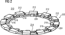
前記一次部品(3、4、222)が、リニアモータ用の一次部品として利用可能な複数の一次部品セグメント(212、213)を連結部材(230)によって環状に連結することで、当該連結された複数の一次部品セグメント(212、213)の全体で以て環状のリニアモータの一次部品として機能するべく形成されたものであり、
前記二次部品(5、6、224)が、複数の二次部品セグメント(5、6、224)を有するものであって、当該連結された複数の二次部品セグメント(5、6、224)の全体が前記一次部品セグメント(212、213)に対応して前記環状のリニアモータの二次部品として機能するべく形成されたものであり、
前記一次部品セグメント(212、213)が、それぞれ個別の複数の電気接続部(220)を有し、
各前記電気接続部(220)が、それぞれ取外し可能な電気接触部を構成する装置を有し、
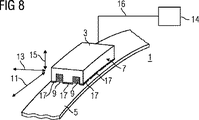
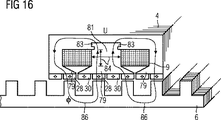
前記一次部品(3、4、222)における前記複数の一次部品セグメント(212、213)の各々が、第1の磁界を生成するための第1の手段(9、10、12、14)として巻線を有し、
前記二次部品(5、6、224)における前記複数の二次部品セグメント(5、6、224)の各々が、磁界を案内するための手段(31、32、33、34、99)を有し、
前記一次部品(3、4、222)における前記複数の一次部品セグメント(212、213)の各々が、別の磁界を生成するための少なくとも1つの別の手段(17、18、20、27、28、29、30)を有し、
前記第1の磁界を生成するための前記第1の手段(9)が、前記第1の磁界と前記別の磁界との重ね合わせが可能であるように、前記別の磁界を生成するための前記別の手段(17、18、20、27、28、29、30)に対応して配置されて、前記一次部品(3、4、222)と前記二次部品(5、6、224)とが同期機として機能するように設定されており、かつ
前記複数の一次部品セグメント(212、213)に更に少なくとも1つの一次部品セグメントを追加的に組立および接続すること又は前記複数の一次部品セグメント(212、213)のうちの少なくとも1つの一次部品セグメントを取り外すことによって当該電気機械(1、2、210)全体としての出力を後から高める又は下げることができるように、各前記一次部品セグメント(212、213)が、その一次部品セグメント用の支持装置(214)に着脱可能に取り付けられている
ことを特徴とする電気機械。 - 前記複数の一次部品セグメント(212、213)および前記複数の二次部品セグメント(5、6、224)のうちの少なくともいずれか一方が、各セグメント同士の間を機械的に接続されて、全体として多角形状を成すように配置されている
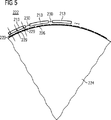
ことを特徴とする請求項1記載の電気機械。 - 前記二次部品(5、6、224)および前記一次部品(3、4、212、213)のうちの少なくともいずれか一方が、ほぼ円形の輪郭を有している
ことを特徴とする請求項1又は2の1つに記載の電気機械。 - 前記二次部品(5、6、224)のほぼ円形の輪郭が、前記一次部品(3、4、212、213)のほぼ円形の輪郭よりも更に円形に近い
ことを特徴とする請求項3記載の電気機械。 - 前記一次部品セグメント(212、213)が、積層薄板を有し、当該積層薄板は、巻線を収容するための溝を有し、当該溝が、互いに平行に配置されている
ことを特徴とする請求項1から4の1つに記載の電気機械。 - 前記磁界を案内するための二次部品側の手段(31、32、33、34、99)が、歯構造を有している
ことを特徴とする請求項1に記載の電気機械。 - フレキソ印刷機である印刷機(200)において、
前記印刷機(200)が、請求項1から6の1つに記載の電気機械(1、2、210)を有している
ことを特徴とする印刷機。 - 前記電気機械(1、2、210)は、当該印刷機(200)の印刷胴(201)を駆動するために設けられたものであり、かつ支持部材(207)に対して支承されたシャフト(206)が設けられており、
前記支持部材(207)が、前記電気機械(1、2、210)における前記一次部品(222)又は前記二次部品(224)のモーメント支柱である
ことを特徴とする請求項7記載の印刷機。 - 前記電気機械(1、2、210)が、前記支持部材(207)と前記印刷胴(201)との間に配置されている
ことを特徴とする請求項7又は8記載の印刷機。 - 前記印刷胴(201)が、2つの前記支持部材(207)によって支承され、当該支持部材(207)と前記印刷胴(201)との間に各々少なくとも1つの前記電気機械(1、2、210)が位置決めされている
ことを特徴とする請求項7又は8記載の印刷機。 - 前記電気機械(1、2、210)が、前記支持部材(207)における前記印刷胴(201)とは反対側を向いている方の側に配置されている
ことを特徴とする請求項7から9の1つに記載の印刷機。
Applications Claiming Priority (3)
| Application Number | Priority Date | Filing Date | Title |
|---|---|---|---|
| DE102006013636A DE102006013636B4 (de) | 2006-03-22 | 2006-03-22 | Druckmaschine bzw. elektrische Maschine für eine Druckmaschine |
| DE102006013636.5 | 2006-03-22 | ||
| PCT/EP2007/051345 WO2007107416A1 (de) | 2006-03-22 | 2007-02-12 | Druckmaschine bzw. elektrische maschine für eine druckmaschine |
Publications (3)
| Publication Number | Publication Date |
|---|---|
| JP2009530141A JP2009530141A (ja) | 2009-08-27 |
| JP2009530141A5 JP2009530141A5 (ja) | 2009-10-08 |
| JP5143119B2 true JP5143119B2 (ja) | 2013-02-13 |
Family
ID=38016496
Family Applications (1)
| Application Number | Title | Priority Date | Filing Date |
|---|---|---|---|
| JP2009500796A Expired - Fee Related JP5143119B2 (ja) | 2006-03-22 | 2007-02-12 | 印刷機又は印刷機のための電気機械 |
Country Status (4)
| Country | Link |
|---|---|
| US (1) | US20090051253A1 (ja) |
| JP (1) | JP5143119B2 (ja) |
| DE (1) | DE102006013636B4 (ja) |
| WO (1) | WO2007107416A1 (ja) |
Families Citing this family (4)
| Publication number | Priority date | Publication date | Assignee | Title |
|---|---|---|---|---|
| DE102007002782A1 (de) * | 2007-01-18 | 2008-07-31 | Siemens Ag | Drehantrieb mit geraden Primärteilsegmenten |
| EP2061136A1 (de) * | 2007-11-19 | 2009-05-20 | Siemens Aktiengesellschaft | Elektrischer Direktantrieb für eine Walze |
| FR2925240B1 (fr) † | 2007-12-13 | 2013-03-29 | Defontaine | Couronne d'orientation motorisee |
| EP3280038A1 (de) * | 2016-08-03 | 2018-02-07 | Siemens Aktiengesellschaft | Antriebsvorrichtung |
Family Cites Families (17)
| Publication number | Priority date | Publication date | Assignee | Title |
|---|---|---|---|---|
| US4607197A (en) * | 1978-04-17 | 1986-08-19 | Imc Magnetics Corporation | Linear and rotary actuator |
| US4175489A (en) * | 1978-05-31 | 1979-11-27 | S. A. Martin | Inking and washing circuit for a flexographic printing machine |
| JPS5986469A (ja) * | 1982-11-09 | 1984-05-18 | Yaskawa Electric Mfg Co Ltd | リニヤステツピングモ−タ |
| JPS61161952A (ja) * | 1985-01-09 | 1986-07-22 | Yaskawa Electric Mfg Co Ltd | 3相リニア誘導子形モ−タ |
| DE68910649T2 (de) * | 1988-11-22 | 1994-05-19 | Shinko Electric Co Ltd | Betätigungsgerät mit starker magnetischer Schiebekraft. |
| DE4138479C3 (de) * | 1991-11-22 | 1998-01-08 | Baumueller Nuernberg Gmbh | Verfahren und Anordnung für einen Elektromotor zum Antrieb eines Drehkörpers, insbesondere des druckgebenden Zylinders einer Druckmaschine |
| EP0738591B1 (de) * | 1995-04-15 | 1999-01-27 | Heidelberger Druckmaschinen Aktiengesellschaft | Übertragungszylinder mit elektromotorischer Antriebseinheit |
| DE19629811A1 (de) * | 1996-07-24 | 1998-01-29 | Roland Man Druckmasch | Farbwerk für Rotationsdruckmaschinen |
| DE19720952C2 (de) * | 1997-05-17 | 2001-02-01 | Roland Man Druckmasch | Schwenkbarer, durch einen elektrischen Einzelantrieb angetriebener Zylinder |
| DE19754323A1 (de) * | 1997-12-08 | 1999-06-10 | Fischer & Krecke Gmbh & Co | Druckmaschine |
| ES2209702T3 (es) * | 2000-03-03 | 2004-07-01 | Rexroth Indramat Gmbh | Accionamiento para cilindros de una maquina de imprenta. |
| DE10243732B4 (de) * | 2001-10-19 | 2018-08-09 | Heidelberger Druckmaschinen Ag | Antriebssystem für einen Zylinder einer Druckmaschine |
| WO2004017497A1 (de) * | 2002-07-26 | 2004-02-26 | W.B.T.-S.A. World Business Technology | Generator für den einsatz bei windkraftanlagen oder wasserkrafträdern |
| DE10327218B4 (de) * | 2003-06-17 | 2015-08-06 | Schaeffler Technologies AG & Co. KG | Direktantrieb für einen Zylinder einer Druckmaschine |
| DE102004045992A1 (de) * | 2004-09-22 | 2006-04-06 | Siemens Ag | Elektrische Maschine |
| DE202005005325U1 (de) * | 2005-04-04 | 2005-06-23 | Fischer, Peter | Elektrischer Antrieb für eine Dreheinheit |
| DE102005019112A1 (de) * | 2005-04-25 | 2006-10-26 | Siemens Ag | Kombinationsantrieb mit Hybridreluktanzmotor |
-
2006
- 2006-03-22 DE DE102006013636A patent/DE102006013636B4/de not_active Expired - Fee Related
-
2007
- 2007-02-12 WO PCT/EP2007/051345 patent/WO2007107416A1/de active Application Filing
- 2007-02-12 US US12/224,907 patent/US20090051253A1/en not_active Abandoned
- 2007-02-12 JP JP2009500796A patent/JP5143119B2/ja not_active Expired - Fee Related
Also Published As
| Publication number | Publication date |
|---|---|
| US20090051253A1 (en) | 2009-02-26 |
| WO2007107416A1 (de) | 2007-09-27 |
| DE102006013636B4 (de) | 2012-02-09 |
| DE102006013636A1 (de) | 2007-10-11 |
| JP2009530141A (ja) | 2009-08-27 |
Similar Documents
| Publication | Publication Date | Title |
|---|---|---|
| JP4376863B2 (ja) | 永久磁石型回転機 | |
| JP2019140895A (ja) | 回転電機駆動システム | |
| JP2009531006A (ja) | 電気機械 | |
| JPWO2019045017A1 (ja) | 電磁装置 | |
| JP5610989B2 (ja) | 回転電動機 | |
| US20200220398A1 (en) | Permanent magnet rotating electric machine | |
| JP2009240158A (ja) | 移動磁界同期acモータ | |
| JP5653997B2 (ja) | ステップ間隔の短いステッピングモータ | |
| JP5462877B2 (ja) | 永久磁石型ステッピングモータ | |
| JP3885732B2 (ja) | 永久磁石埋め込み同期モータ | |
| US8917004B2 (en) | Homopolar motor-generator | |
| JP2011078202A (ja) | アキシャルギャップモータ | |
| JP4423294B2 (ja) | 多相ステップモータ | |
| JP5143119B2 (ja) | 印刷機又は印刷機のための電気機械 | |
| US20080290754A1 (en) | AC Motor | |
| JP5386925B2 (ja) | 円筒形リニアモータ | |
| JP5499549B2 (ja) | 二重回転子構造磁気支持モータ及び該二重回転子構造磁気支持モータを搭載したターンテーブル | |
| JP2014103789A (ja) | 永久磁石埋込型モータ | |
| JP2008187863A (ja) | アキシャルギャップ型回転電機及び圧縮機 | |
| JP5453933B2 (ja) | 電磁ユニット | |
| JP3944766B2 (ja) | 永久磁石形同期リニアモータ | |
| JP2006025486A (ja) | 回転電機 | |
| JP2017063594A (ja) | ブラシレスモータ | |
| JP3797488B2 (ja) | 多極回転電機 | |
| JP5114135B2 (ja) | アキシャルギャップ型モータ |
Legal Events
| Date | Code | Title | Description |
|---|---|---|---|
| A521 | Written amendment |
Free format text: JAPANESE INTERMEDIATE CODE: A523 Effective date: 20090715 |
|
| A621 | Written request for application examination |
Free format text: JAPANESE INTERMEDIATE CODE: A621 Effective date: 20090715 |
|
| A977 | Report on retrieval |
Free format text: JAPANESE INTERMEDIATE CODE: A971007 Effective date: 20111020 |
|
| A131 | Notification of reasons for refusal |
Free format text: JAPANESE INTERMEDIATE CODE: A131 Effective date: 20111025 |
|
| A521 | Written amendment |
Free format text: JAPANESE INTERMEDIATE CODE: A523 Effective date: 20111228 |
|
| RD03 | Notification of appointment of power of attorney |
Free format text: JAPANESE INTERMEDIATE CODE: A7423 Effective date: 20111228 |
|
| A131 | Notification of reasons for refusal |
Free format text: JAPANESE INTERMEDIATE CODE: A131 Effective date: 20120306 |
|
| A601 | Written request for extension of time |
Free format text: JAPANESE INTERMEDIATE CODE: A601 Effective date: 20120531 |
|
| A602 | Written permission of extension of time |
Free format text: JAPANESE INTERMEDIATE CODE: A602 Effective date: 20120607 |
|
| A601 | Written request for extension of time |
Free format text: JAPANESE INTERMEDIATE CODE: A601 Effective date: 20120706 |
|
| A602 | Written permission of extension of time |
Free format text: JAPANESE INTERMEDIATE CODE: A602 Effective date: 20120713 |
|
| A521 | Written amendment |
Free format text: JAPANESE INTERMEDIATE CODE: A523 Effective date: 20120719 |
|
| A131 | Notification of reasons for refusal |
Free format text: JAPANESE INTERMEDIATE CODE: A131 Effective date: 20120904 |
|
| A521 | Written amendment |
Free format text: JAPANESE INTERMEDIATE CODE: A523 Effective date: 20120912 |
|
| TRDD | Decision of grant or rejection written | ||
| A01 | Written decision to grant a patent or to grant a registration (utility model) |
Free format text: JAPANESE INTERMEDIATE CODE: A01 Effective date: 20121023 |
|
| A01 | Written decision to grant a patent or to grant a registration (utility model) |
Free format text: JAPANESE INTERMEDIATE CODE: A01 |
|
| A61 | First payment of annual fees (during grant procedure) |
Free format text: JAPANESE INTERMEDIATE CODE: A61 Effective date: 20121120 |
|
| FPAY | Renewal fee payment (event date is renewal date of database) |
Free format text: PAYMENT UNTIL: 20151130 Year of fee payment: 3 |
|
| R150 | Certificate of patent or registration of utility model |
Free format text: JAPANESE INTERMEDIATE CODE: R150 |
|
| R250 | Receipt of annual fees |
Free format text: JAPANESE INTERMEDIATE CODE: R250 |
|
| R250 | Receipt of annual fees |
Free format text: JAPANESE INTERMEDIATE CODE: R250 |
|
| LAPS | Cancellation because of no payment of annual fees |