JP5114799B2 - Vibration isolator - Google Patents
Vibration isolator Download PDFInfo
- Publication number
- JP5114799B2 JP5114799B2 JP2008170133A JP2008170133A JP5114799B2 JP 5114799 B2 JP5114799 B2 JP 5114799B2 JP 2008170133 A JP2008170133 A JP 2008170133A JP 2008170133 A JP2008170133 A JP 2008170133A JP 5114799 B2 JP5114799 B2 JP 5114799B2
- Authority
- JP
- Japan
- Prior art keywords
- vibration
- liquid chamber
- chamber
- storage chamber
- elastic body
- Prior art date
- Legal status (The legal status is an assumption and is not a legal conclusion. Google has not performed a legal analysis and makes no representation as to the accuracy of the status listed.)
- Expired - Fee Related
Links
Images


Description
この発明は、例えば自動車や一般産業用機械等において、エンジン等の振動を生じる部分と車体等の振動を受ける部分との間に適用され、これら振動を生じる部分から振動を受ける部分へ伝達される振動を減衰及び吸収する防振装置に関する。 The present invention is applied, for example, between a portion that generates vibrations of an engine or the like and a portion that receives vibrations of a vehicle body or the like in an automobile or a general industrial machine, and is transmitted from these portions that generate vibrations to a portion that receives vibrations. The present invention relates to a vibration isolator that attenuates and absorbs vibration.
振動発生源となる自動車用エンジンや一般産業用機械の原動機等を、その振動を車体や機械本体へ伝達させないように支持する防振装置としては、例えば、特許文献1に開示されている液体封入式のものが知られている。この特許文献1に示されている防振装置には、外筒、ゴム弾性体及びダイヤフラムにより外部から密封された液室空間が形成されており、この液室空間は、振動入力方向に互いに離間かつ対向して配置された2つの内部隔壁により、ゴム弾性体を隔壁の一部とする主液室と、ダイヤフラムを隔壁の一部とする副液室とに仕切られ、これら主液室と副液室とは、制限通路を介して連通され、これら主液室、副液室及び制限通路内には、水又はエチレングリコール等の液体が充填されている。この防振装置では、2つの内部隔壁間に円柱状の空間である収納室が形成されており、その収納室より外周側には制限通路が形成されている。それぞれの内部隔壁には、開口部が形成され、収納室内は、かかる開口部を通じで主液室及び副液室にそれぞれ連通している。さらにこの防振装置では、入力振動の振動方向に沿って振動可能とされた円板状の可動プレート(流通制御板)が収納室内に配置されている。 As an anti-vibration device for supporting an automobile engine or a motor for a general industrial machine, which is a vibration generation source, so as not to transmit the vibration to a vehicle body or a machine main body, for example, a liquid enclosure disclosed in Patent Document 1 The formula is known. In the vibration isolator shown in Patent Document 1, a liquid chamber space sealed from the outside is formed by an outer cylinder, a rubber elastic body, and a diaphragm, and the liquid chamber spaces are separated from each other in the vibration input direction. The two internal partition walls arranged opposite to each other are partitioned into a main liquid chamber having a rubber elastic body as a part of the partition wall and a sub liquid chamber having a diaphragm as a part of the partition wall. The liquid chamber communicates with the restriction passage, and the main liquid chamber, the sub liquid chamber, and the restriction passage are filled with a liquid such as water or ethylene glycol. In this vibration isolator, a storage chamber which is a cylindrical space is formed between two internal partition walls, and a restriction passage is formed on the outer peripheral side of the storage chamber. Each internal partition has an opening, and the storage chamber communicates with the main liquid chamber and the sub liquid chamber through the opening. Furthermore, in this vibration isolator, a disc-shaped movable plate (distribution control plate) that can vibrate along the vibration direction of the input vibration is disposed in the storage chamber.
このように構成された防振装置では、振動入力時にゴム弾性体が弾性変形することにより振動が減衰吸収される。このとき、入力振動の周波数が所定の値よりも低い低周波振動の場合には、流通制御板が2つの内部隔壁にそれぞれ形成された開口部を交互に塞ぐ状態となるので、液体が収納室内を通って主液室と副液室の間を実質的に流通することがなく、その結果、制限通路のみを通じて主液室と副液室との間で液体が相互に流通し、これにより制限通路内を流通する液体に共振現象(液柱共振)が生じて入力振動は減衰される。一方、入力振動の周波数が所定の値よりも高い高周波振動の場合には、制限通路が実質な目詰まり状態となるが、流通制御板が収納室内で入力振動に同期して振動することにより、収納室、特には上記開口部を通じて主液室と副液室との間で液体の流通が生じるので、主液室内の液圧上昇に伴うゴム弾性体の動ばね定数の上昇は抑制され、その結果、ゴム弾性体の弾性変形等により高周波振動もまた効果的に減衰される。
しかしながら、上述したような従来の防振装置では、流通制御板は、高周波振動の入力時に収納室内にて入力振動の振幅方向に沿って振動し、収納室(内部隔壁)内の内壁面に入力振動の周波数に対応する周期で繰り返し衝突する。これにより、このような防振装置が適用された車両では、防振装置における流通制御板と内部隔壁との衝突に起因する打音が高周波振動の入力時に、具体的には、車両のアイドリング運転時に発生し、この打音が車体を通して車内へ不快な異音として伝達されることがある。 However, in the conventional vibration isolator as described above, the flow control plate vibrates along the amplitude direction of the input vibration in the storage chamber when high-frequency vibration is input, and is input to the inner wall surface in the storage chamber (internal partition wall). Colliding repeatedly with a period corresponding to the frequency of vibration. As a result, in a vehicle to which such a vibration isolator is applied, when the hitting sound resulting from the collision between the flow control plate and the internal partition wall in the vibration isolator is input with high frequency vibration, specifically, the idling operation of the vehicle is performed. Occasionally, this hitting sound may be transmitted through the vehicle body as an unpleasant noise.
それゆえ、この発明は、これらの問題点を解決することを課題とするものであり、その目的は、流通制御板により収納室を介して主液室と副液室との間の液体の流通を制御することにより広い周波数域の入力振動を効果的に減衰可能とすることを前提に、流通制御板と内部隔壁の内壁面との衝突に起因する異音の音圧を低減可能な防振装置を提供することにある。 Therefore, the present invention has an object to solve these problems, and an object of the present invention is to distribute liquid between the main liquid chamber and the sub liquid chamber through the storage chamber by the flow control plate. Anti-vibration that can reduce the sound pressure of abnormal noise caused by the collision between the flow control plate and the inner wall of the internal partition, assuming that input vibration in a wide frequency range can be effectively damped by controlling To provide an apparatus.
前記の目的を達成するため、この発明は、振動入力方向で相互に所定の距離を隔てて配置された第1及び第2の支持体と、これら第1の支持体と第2の支持体との間に介装されたゴム弾性体と、液体が封入され、前記ゴム弾性体を隔壁の一部として該ゴム弾性体の変形に伴い内容積が変化する主液室と、液体が封入され、液圧変化に応じて内容積が拡縮可能とされた副液室と、前記主液室と前記副液室との間を連通する制限通路と、振動入力方向で所定の距離を隔てて相互に対向して配置されて中空状の収納室を構成する、樹脂で構成した第1及び第2の内部隔壁と、前記収納室内に配置され、前記第1及び第2の支持体への所定の入力振動に同期して振動するとともに、該収容室内を浮遊する流通制御板と、前記第1の内部隔壁を弾性支持する弾性部材と、を具える防振装置である。 In order to achieve the above-mentioned object, the present invention includes first and second supports disposed at a predetermined distance from each other in the vibration input direction, and the first support and the second support. A rubber elastic body interposed between the main liquid chamber, a liquid is sealed, and the rubber elastic body is used as a part of a partition to change the internal volume with deformation of the rubber elastic body, and a liquid is sealed, A sub liquid chamber whose internal volume can be expanded and contracted according to a change in the liquid pressure, a restriction passage communicating between the main liquid chamber and the sub liquid chamber, and a predetermined distance in the vibration input direction. First and second internal partition walls made of resin, which are arranged opposite to each other to form a hollow storage chamber, and a predetermined input to the first and second support bodies which are arranged in the storage chamber with vibrating in synchronism with the vibration, the flow control plate floating the housing chamber, elastically supporting the first inner septum wall An elastic member that is a vibration isolation apparatus Ru comprising a.
かかる構成を採用することにより、支持体への振動入力時にゴム弾性体が弾性変形することにより振動が減衰吸収される。また、入力振動の振幅が所定の値よりも大きい場合には、流通制御板が該入力振動に同期して振動して主液室と副液室との間の液体の流通を制限する結果、液体は制限通路のみを介して主液室と副液室との間を流通するので、制限通路内を流通する液体に共振現象(液柱共振)が生じ、この液柱共振の作用によって入力振動は効果的に減衰される。 By adopting such a configuration, the vibration is attenuated and absorbed by elastic deformation of the rubber elastic body at the time of vibration input to the support. When the amplitude of the input vibration is larger than a predetermined value, the flow control plate vibrates in synchronization with the input vibration and restricts the liquid flow between the main liquid chamber and the sub liquid chamber, Since the liquid flows between the main liquid chamber and the sub liquid chamber only through the restriction passage, a resonance phenomenon (liquid column resonance) occurs in the liquid flowing in the restriction passage, and the input vibration is caused by the action of the liquid column resonance. Is effectively attenuated.
一方、入力振動の振幅が所定の値よりも小さい場合には、制限通路が実質的に目詰まり状態となり、この制限通路を介して液体の流通は行われ難くなるものの、流通制御板が収納室内で入力振動に同期して振動することにより、収納室内を通って主液室と副液室との間で液体の流通が生じるので、主液室内の液圧上昇に伴う動ばね定数の上昇は抑制される。従って、振幅が小さい振動の入力時もゴム弾性体の動ばね定数は低く維持されることから、当該ゴム弾性体の弾性変形等により振動は効果的に減衰される。 On the other hand, when the amplitude of the input vibration is smaller than the predetermined value, the restriction passage is substantially clogged, and it is difficult for the liquid to flow through the restriction passage. Since the liquid flows between the main liquid chamber and the sub liquid chamber through the storage chamber by vibrating in synchronization with the input vibration, the increase of the dynamic spring constant accompanying the increase in the liquid pressure in the main liquid chamber is It is suppressed. Accordingly, since the dynamic spring constant of the rubber elastic body is kept low even when vibration with a small amplitude is input, the vibration is effectively damped by the elastic deformation of the rubber elastic body.
さらに、この防振装置は、第1の内部隔壁を弾性支持する弾性部材を具えることから、弾性支持された内部隔壁においては、振動入力時に流通制御板が収納室内で振動しかかる内部隔壁の内壁面に衝突しても、その衝突により生じる衝撃は弾性部材により吸収される。従って、流通制御板が収納室内で振動し内部隔壁の内壁面に衝突することにより生じる打音の音圧は低減されるとともに、かかる衝撃が車体や機械本体等の振動受側へ伝達されることがない。 Furthermore, the anti-vibration device, since comprising an elastic member that the first inner septum wall for elastically supporting, in the elastic supported inner partition, inner partition the flow control plate during vibration input Kakaru vibrates in storage chamber Even if it collides with the inner wall surface, the impact caused by the collision is absorbed by the elastic member. Therefore, the sound pressure of the hitting sound generated when the distribution control plate vibrates in the storage chamber and collides with the inner wall surface of the internal partition wall is reduced, and the impact is transmitted to the vibration receiving side of the vehicle body or machine body. There is no.
また、この発明の防振装置においては、第1及び第2の内部隔壁より外周側に制限通路を配置する。そしてここでは、前記第1及び第2の内部隔壁のうちの第1の内部隔壁だけを、前記弾性部材により弾性支持させる。 Further, in the vibration isolating apparatus of the present invention, in which to place the restricted passage from the first and second inner partition on the outer peripheral side. Here, only the first inner partition of the first and second inner partitions is elastically supported by the elastic member.
さらに、この発明の防振装置においては、弾性部材は、第1の内部隔壁を弾性支持する。 Further, in the vibration isolating apparatus of the present invention, the elastic member, the first inner partition you elastic support.
さらに、この発明の防振装置においては、流通制御板は、収納室内に浮遊するものとする。 Further, in the vibration isolating apparatus of the present invention, the flow control plate shall be suspended in the housing chamber.
なお、この発明の防振装置においては、第1の内部隔壁及び第2の内部隔壁を樹脂で構成する。 Note that, in the vibration isolating apparatus of the present invention, that make up the first inner partition and the second inner partition resin.
この発明の防振装置によれば、流通制御板により収納室を介して主液室と副液室との間の液体の流通を制御することにより広い周波数域の入力振動を効果的に減衰可能とすることを前提に、流通制御板と内部隔壁の内壁面との衝突に起因する異音の音圧を低減することが可能となる。 According to the vibration isolator of the present invention, input vibrations in a wide frequency range can be effectively damped by controlling the flow of the liquid between the main liquid chamber and the sub liquid chamber via the storage chamber by the flow control plate. As a premise, it is possible to reduce the sound pressure of abnormal noise caused by the collision between the flow control plate and the inner wall surface of the internal partition wall.
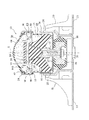
以下、本発明の実施形態に係る防振装置について図面を参照しつつ詳細に説明する。ここで、図1は、この発明の実施形態に係る防振装置の断面図であり、図2は、この実施例の防振装置に適用される後述のオリフィス複合体の断面図であり、図3は、図2に示すオリフィス複合体の分解斜視図である。 Hereinafter, a vibration isolator according to an embodiment of the present invention will be described in detail with reference to the drawings. Here, FIG. 1 is a cross-sectional view of a vibration isolator according to an embodiment of the present invention, and FIG. 2 is a cross-sectional view of a later-described orifice complex applied to the vibration isolator of this embodiment. 3 is an exploded perspective view of the orifice complex shown in FIG.
図1に示すように、防振装置10は、振動入力方向(図1で示す軸線Sと同一方向であり、以下、「軸方向」という。)で相互に所定の距離を隔てて配置された第1及び第2の支持体として、円筒状の内筒金具12とその径方向外側に同軸で配置された円筒状の外筒金具14とを具える。内筒金具12は振動発生側であるエンジン側に連結され、外筒金具14は振動受側である車体側へ連結される。これら内筒金具12と外筒金具14との間には、吸振主体となるゴム弾性体16が配置されている。内筒金具12は、その上端側(図1では上側)が外筒金具14内へ挿入されつつその下端側(図1では下側)が外筒金具14の下端側の開口部を通って外筒金具14の下方まで突出している。外筒金具14には、その軸方向中間部に設けられた段差部18に対して上端側の部分に下端側の部分よりも直径が拡大された拡径部20が形成されている。また外筒金具14には、その下端部に下方へ向って直径がテーパ状に縮小するテーパ部22が屈曲形成されるとともに、拡径部20の上端部に装置の組立時に内周側へ屈曲されるかしめ部24が形成されている。
As shown in FIG. 1, the
外筒金具14は、その下端側が略カップ状の連結筒26内に嵌挿固定されており、この連結筒26は、その下端側が有底円筒状のホルダ金具28内に嵌挿固定されている。外筒金具14は、その下端部が連結筒26の下側隔壁部材に当接するまで連結筒26内へ挿入されている。またホルダ金具28には、その外周面に複数の脚部30、32が溶接等により固定されており、この脚部30、32の先端側に形成された連結穴33を挿通するボルト(図示省略)により、ホルダ金具28は車体側へ締結固定される。その結果、外筒金具14が、連結筒26及びホルダ金具28を介して車体側へ連結固定される。
The lower end side of the outer cylinder fitting 14 is fitted and fixed in a substantially cup-shaped connecting
内筒金具12の下端側は、連結筒26の底板部に形成された開口部27を通って連結筒26の下方まで突出しており、この内筒金具12の下端部には、ボルト34によりエンジン連結用のブラケット36の基端部が締結固定されている。このブラケット36は、ホルダ金具28の側面部に形成された開口部(図示省略)を通って径方向外側へ延出しており、ブラケット36の先端側にはボルト等によりエンジン(図示省略)が締結固定される。またブラケット36の基端部は、ストッパゴム38でその周囲を被覆されており、このストッパゴム38の上面部は連結筒26の底板部に圧接している。これにより、ブラケット36は軸方向に沿って過大に変位することがなく、また大荷重の入力によりブラケット36が連結筒26又はホルダ金具28へ衝突した際にも衝突音の発生が防止される。
The lower end side of the inner cylinder fitting 12 protrudes to the lower side of the
ゴム弾性体16は、外筒金具14内へ挿入された内筒金具12の上端側に加硫接着されるとともに、外筒金具14の下端側に加硫接着されており、内筒金具12と外筒金具14とを弾性的に連結している。またゴム弾性体16には、外筒金具14の内周面に沿って延び該内周面を被覆する薄肉状の被覆部40が一体的に形成されている。
The rubber
図1に示すように、外筒金具14内には、オリフィス複合体100(図2に詳細を示す)が挿入されており、このオリフィス複合体100下面における外周部は、被覆部40を介して段差部18に当接している。そして、このオリフィス複合体100が外筒金具14内に挿入された後に、軸方向上側に向けて凸状に形成されるとともに外周側に支持リング42が埋設されたゴム製のダイヤフラム44が同様に外筒金具14内に挿入され、円筒状であったかしめ部24及び支持リング42は内周側へテーパ状に屈曲される。その結果、オリフィス複合体100は外筒金具14内にて段差部18とかしめ部24との間に固定されるとともに、ダイヤフラム44はオリフィス複合体100とかしめ部24との間に固定されることになる。
As shown in FIG. 1, an orifice complex 100 (details are shown in FIG. 2) is inserted into the outer tube fitting 14, and the outer peripheral portion of the bottom surface of the
ここでオリフィス複合体100は、図2及び図3に示すように、略筒状に形成されるとともにその外周面に周方向へ延在する凹状の溝部46が設けられた第1オリフィス構造体48を具える。溝部46は軸線Sを中心とする周方向に沿ってC字状に延在しており、第1オリフィス構造体48には、溝部46の一端部から下方へ向って溝部46の下部側が切り欠かれて連通口50が形成されるとともに、溝部46の他端部から上方へ向って溝部46の上部側が切り欠かれて連通口52が形成されている。溝部46は、図1に示すように、その外周側が被覆部40を介して外筒金具14の内周面により閉止されることにより、後述する主液室56と副液室58とを連通させる制限通路60を構成する。
Here, as shown in FIGS. 2 and 3, the
防振装置10内には、外筒金具14、ゴム弾性体16及びダイヤフラム44により外部から密閉された液室空間が形成されており、この液室空間は、オリフィス複合体100によりゴム弾性体16を隔壁の一部とする主液室56と、ダイヤフラム44を隔壁の一部とする副液室58とに仕切られている。防振装置10では、副液室58の隔壁の一部を形成するダイヤフラム44の外側が大気空間とされており、これにより、ダイヤフラム44は、副液室58内の液圧変化に応じて副液室58の内容積を拡縮するように変形可能とされている。また主液室56は、その内容積がゴム弾性体16の弾性変形に伴って拡縮する。
In the
主液室56、副液室58及び制限通路60内には、水、エチレングリコール等の液体が充填されており、この液体は制限通路60を通して主液室56と副液室58との間で流通可能とされている。ここで、制限通路60は、その路長及び断面積がシェイク振動の振幅及び周波数に適合するように設定(チューニング)されている。
The main
第1オリフィス構造体48には、図2に示すように、その上端部付近から径方向内側及び軸方向上側に向かって延びる突出部62が形成され、さらに第1オリフィス構造体48の上面部であって突出部62の径方向外側には平面状のフランジ面64が形成されている。突出部62の径方向内方には、第1の内部隔壁として、第1オリフィス構造体48の内径よりも僅かに小さい直径を有する略円板状の下側隔壁部材66が配置されている。そして、これら下側隔壁部材66と第1オリフィス構造体48とは弾性部材68を介して連結されており、弾性部材68は、図示のように下側隔壁部材66の上面全体を覆いつつその側部をも包み込めるように形成され、弾性部材68の外周面は第1オリフィス構造体48の内周面に例えば接着剤等を用いて固着されている。これにより、下側隔壁部材66は第1オリフィス構造体48に弾性的に支持されることとなる。弾性部材68は、ゴムの他、熱可塑性エラストマー等の材料で構成することができる。
As shown in FIG. 2, the
下側隔壁部材66の軸方向上方には、下側隔壁部材66に対して所定の距離離間し、かつ対向するよう第2の内部隔壁としての上側隔壁部材70が配置されている。上側隔壁部材70には、第1オリフィス構造体48の突出部62に対応する円形凸状の外嵌部72が形成されると共に、この外嵌部72の下端部から径方向外側へ延出する環状のフランジ部74が一体的に形成されている。図2に示すように、オリフィス複合体100では、上側隔壁部材70のフランジ部74を第1オリフィス構造体48のフランジ面64に当接させることにより、主液室56及び副液室58から仕切られた収納室76が形成される。収納室76内には、軸方向に沿った距離が略一定とされた円柱状の空間が形成される。また上側隔壁部材70のフランジ部74には、図3に示すように、外周端から径方向内側へ向って略矩形状に切り欠かれた切欠部78が形成されており、この切欠部78を通して、制限通路60の連通口52は副液室58へ連通している。
Above the lower
図3に示すように、上側隔壁部材70には、径方向外側へ向かうに連れて周方向に沿った寸法が広がる扇状の開口部80が複数個(この実施例では、4個)穿設されている。この開口部80を通して収納室76は副液室58と互いに連通している。同様に、下側隔壁部材66にも上側隔壁部材70の開口部80と同様の形状及び開口面積を有する開口部82が弾性部材68を貫通して複数個(この実施例では、4個)穿設されている。この開口部82を通して収納室76は主液室56と互いに連通している。
As shown in FIG. 3, the upper
図2及び3に示すように、収納室76内にはゴム、樹脂等を素材として円板状に形成された流通制御板としての可動板84が配置されている。この可動板84は、例えば、全体として厚さが略一定の薄肉円板状に形成されており、その外径が収納室76の内径よりも若干小さくなっている。なお、流通制御板は、入力振動に同期して振動し、開口部80、82を交互に開閉し得ればどのようなものでも良く、図示例のような可動板84の他、例えば、柔軟な薄肉円板状の弾性膜(図示省略)を用いても良い。この場合、弾性膜を、その外周縁を、上側隔壁部材70又は下側隔壁部材66に接着させ、あるいは上側隔膜部材70のフランジ部74と第1オリフィス部材50のフランジ面64との間に挟み込ませることにより収容室76内に固定することができる。
As shown in FIGS. 2 and 3, a
可動板84は、その厚さtp(図2参照)が収納室76の軸方向に沿った離間距離ts(図2参照)よりも所定寸法短くなっている。具体的には、可動板84の厚さtpと収納室76の離間距離tsとの差は、入力振動のうち相対的に低周波数の振動であるシェイク振動の振幅よりも短く、かつ相対的に高周波数の振動であるアイドル振動の振幅よりも長くなるように設定されている。これにより、収納室76内では、可動板84と下側隔壁部材66及び上側隔壁部材70との間に軸方向に沿って低周波振動と高周波振動との振幅差に対応する幅の隙間が形成される。これにより、収納室76内に収納された可動板84は、低周波振動と高周波振動との振幅差に対応する振幅で軸方向に沿って往復移動(振動)することが可能になる。これら上側隔壁部材70、下側隔壁部材66、開口部80、82及び可動板84により第2オリフィス構造体が構成されている。
The
かかる実施例の防振装置10にあっては、エンジン又は車体側からの振動入力時に、この振動により吸振主体であるゴム弾性体16が弾性変形する。これにより、ゴム弾性体16の内部摩擦等によって入力振動が減衰吸収される。また防振装置10では、エンジン又は車体側からの振動入力時に、この振動入力に同期してゴム弾性体16が弾性変形すると、主液室56の内容積が拡縮すると共に液圧が変化する。この液圧変化に伴って、制限通路60を通して主液室56と副液室58との間に液体が相互に流通すると共に、主液室56に連通した収納室76内に収納された可動板84には、入力振動に同期して周期的に変化する液圧(圧力波)が作用し、この圧力波を受けた可動板84は、収納室76内で軸方向に沿って振動し、その上面部及び下面部を上側隔壁部材50の下側隔壁部材に対して当接及び離間する動作を繰り返す。可動板84が下方へ移動して下側隔壁部材66に当接すると、可動板84の下面部により下側隔壁部材72に開口する開口部82が閉塞され、可動板84が下側隔壁部材72から上方へ離間すると、開口部82が開放される。また可動板84がさらに上方へ移動して上側隔壁部材70に当接すると、可動板84の上面部により上側隔壁部材70に開口する開口部80が閉塞される。
In the
防振装置10では、入力振動の周波数が低く、その振幅が所定値以上の場合、具体的には、入力振動の周波数がシェイク振動の周波数(例えば、8〜12Hz)以下である場合、主液室56内の液圧が副液室58内に液圧に対して変化している期間には、可動板84により開口部80,82の一方が閉塞される。これにより、シェイク振動の入力時には、収納室76内を通って液体が主液室56と副液室58との間を実質的に流通することがなくなり、制限通路60のみを通して主液室56と副液室58との間で液体が相互に流通する。この結果、防振装置10によれば、入力振動が特にシェイク振動である場合には、制限通路60を流通する液体に共振現象(液柱共振)が生じ、この液柱共振の作用によって入力振動を特に効果的に減衰できる。
In the
一方、入力振動の周波数がシェイク振動の周波数よりも高く、その振幅が小さい場合、例えば、入力振動がアイドル振動(例えば、20〜30Hz)である場合には、シェイク振動に適合するようにチューニングされた制限通路60が目詰まり状態となり、制限通路60には液体が流れ難くなるが、可動板84が収納室76内で入力振動に同期して振動することにより、主液室56内の液圧が副液室58内の液圧に対して実質的に変化している期間に、可動板84と下側隔壁部材66及び上側隔壁部材70の一方との間に隙間が形成され、開口部80,82が交互に開放された状態となるので、収納室76を通って主液室56と副液室58との間で液体の流通が生じる。この結果、主液室56内の液圧上昇が抑制され、ひいては主液室56内の液圧上昇に起因する装置の動ばね定数の上昇が抑制されることから、このような高周波振動の入力時もゴム弾性体16の動ばね定数を低く維持し、このゴム弾性体16の弾性変形により高周波振動も効果的に吸収できる。
On the other hand, when the frequency of the input vibration is higher than the frequency of the shake vibration and the amplitude thereof is small, for example, when the input vibration is an idle vibration (for example, 20 to 30 Hz), the input vibration is tuned to match the shake vibration. The restricting
また防振装置10では、可動板84から下側隔壁部材66に加わった衝撃力を弾性部材68の弾性作用により効果的に緩衝できるので、装置への振動入力時に主液室56内からの圧力波を受けた可動板84が収納室76内で振動し、入力振動に同期して可動板84が収納室76の内壁(上側隔壁部材70及び下側隔壁部材66)に繰り返し衝突する現象が生じても、弾性部材68により可動板84から下側隔壁部材66に加わった衝撃力を緩衝でき、かかる衝突により生じる打音の音圧を低減することができるとともに、この衝撃力が車体や機械本体等の振動受側へ伝達されることを抑制できる。
Further, in the
制限通路60は、上側隔壁部材70及び下側隔壁部材66より内周側に配置することもできるが、この実施例の防振装置10のように、制限通路60は、上側隔壁部材70及び下側隔壁部材66の外周側に配置することが好ましい。前述のように、防振装置10ではシェイク振動の振幅及び周波数に適合するよう制限通路60の長さ及び断面積を設定する必要があり、このように制限通路60を、上側隔壁部材70及び下側隔壁部材66の外周側に配置することで装置を大型化することなく比較的容易に制限通路60の必要長さを確保することができるからである。
The restricting
さらにこの実施例の防振装置10によれば、下側隔膜部材66が弾性部材68を介して、特に軸方向に変位可能に支持されていることから、過大な振動の入力により主液室56内に所定以上の負圧が生じたときに、主液室56内に面する下側隔膜部材66が主液室56側に変位し、これにより主液室56内の負圧が緩和されるので、主液室56内におけるキャビテーションの発生を低減することができる。
Furthermore, according to the
さらにこの実施例の防振装置10によれば、可動板84は収納室76内を浮遊していることから、振動に対する可動板84の応答性を向上させることができる。また、低周波振動の入力時には可動板84は確実に開口部80、82を閉鎖することができる。
Furthermore, according to the
なお、防振装置10では、上側隔膜部材70及び下側隔膜部材66を金属等で形成することができるが樹脂で形成することが好ましい。防振装置10を軽量化することができるとともに腐食等のおそれがなく耐久性に優れるからである。従来、上側隔膜部材70及び下側隔膜部材66を樹脂で構成することは、特に組立時に径方向内側に向けて防振装置10の外部から圧力負荷が加わることから強度の観点で難しいとされていたが、この防振装置10では弾性部材68にかかる圧力負荷を吸収させることができるので上側隔膜部材70及び下側隔膜部材66を樹脂で構成することができる。
In the
また、防振装置10では弾性部材68は下側隔膜部材66と第1オリフィス構造体48との間に設けられているが、上側隔膜部材70と第1オリフィス構造体48との間に設けられていても良い。さらにいえば、弾性部材68を下側隔膜部材66と第1オリフィス構造体48との間、及び上側隔膜部材70と第1オリフィス構造体48との間の両方に設けることが好ましい。これによれば、弾性部材68が可動板84から下側隔壁部材66及び上側隔壁部材70の双方に加わった衝撃力を緩衝するので、可動板84の収納室76の内壁への衝突よる打音の音圧をより一層低減することができる。
In the
なお、上述したところは、この発明の実施形態の一部を示したに過ぎず、この発明の趣旨を逸脱しない限り、これらの構成を相互に組み合わせたり種々の変更を加えたりすることができる。例えば、弾性部材68は、下側隔壁部材68及び/又は上側隔壁部材70を少なくとも軸方向に弾性変位可能に支持できればどのような構成としても良く、弾性部材68は実施例に限定されず、ベローズやばね等で構成することができる。また弾性部材68は図示例と異なる形状及び配置としても良い。
Note that the above description shows only a part of the embodiment of the present invention, and these configurations can be combined with each other or various modifications can be made without departing from the spirit of the present invention. For example, the
以上の説明から明らかなように、この発明によって、流通制御板により収納室を介して主液室と副液室との間の液体の流通を制御することにより広い周波数域の入力振動を効果的に減衰可能とすることを前提に、流通制御板と内部隔壁の内壁面との衝突に起因する異音の音圧を低減可能な防振装置を提供することが可能となった。 As is apparent from the above description, according to the present invention, by controlling the flow of liquid between the main liquid chamber and the sub liquid chamber via the storage chamber by the flow control plate, it is possible to effectively input vibration in a wide frequency range. Therefore, it is possible to provide a vibration isolator capable of reducing the sound pressure of abnormal noise caused by the collision between the flow control plate and the inner wall surface of the internal partition wall.
10 防振装置
12 内筒金具
14 外筒金具
16 ゴム弾性体
44 ダイヤフラム
48 第1オリフィス構造体
56 主液室
58 副液室
60 制限通路
66 下側隔壁部材
68 弾性部材
70 上側隔壁部材
76 収納室
80、82 開口部
84 可動板
DESCRIPTION OF
Claims (1)
これら第1の支持体と第2の支持体との間に介装されたゴム弾性体と、
液体が封入され、前記ゴム弾性体を隔壁の一部として該ゴム弾性体の変形に伴い内容積が変化する主液室と、
液体が封入され、液圧変化に応じて内容積が拡縮可能とされた副液室と、
前記主液室と前記副液室との間を連通する制限通路と、
振動入力方向で所定の距離を隔てて相互に対向して配置されて中空状の収納室を構成する、樹脂で構成した第1及び第2の内部隔壁と、
前記収納室内に配置され、前記第1及び第2の支持体への所定の入力振動に同期して振動するとともに、該収納室内を浮遊する流通制御板と、
前記第1の内部隔壁を弾性支持する弾性部材と、を具え、
前記第1及び第2の内部隔壁より外周側に前記制限通路を配置し、
前記第1及び第2の内部隔壁のうちの第1の内部隔壁だけを、前記弾性部材により弾性支持してなることを特徴とする防振装置。 First and second supports disposed at a predetermined distance from each other in a vibration input direction;
A rubber elastic body interposed between the first support body and the second support body;
A main liquid chamber in which a liquid is enclosed, and the internal volume of the rubber elastic body changes as the rubber elastic body is deformed with the rubber elastic body as a part of a partition;
A sub-liquid chamber in which liquid is enclosed and the internal volume can be expanded and contracted in accordance with a change in hydraulic pressure;
A restricting passage communicating between the main liquid chamber and the sub liquid chamber;
First and second internal partition walls made of resin, which are arranged to face each other with a predetermined distance in the vibration input direction to form a hollow storage chamber;
A flow control plate that is disposed in the storage chamber, vibrates in synchronization with predetermined input vibrations to the first and second supports , and floats in the storage chamber ;
Comprising a an elastic member for elastically supporting said first internal septum wall,
The restriction passage is arranged on the outer peripheral side from the first and second inner partition walls,
Only the first internal partition of the first and second internal partitions is elastically supported by the elastic member .
Priority Applications (1)
| Application Number | Priority Date | Filing Date | Title |
|---|---|---|---|
| JP2008170133A JP5114799B2 (en) | 2008-06-30 | 2008-06-30 | Vibration isolator |
Applications Claiming Priority (1)
| Application Number | Priority Date | Filing Date | Title |
|---|---|---|---|
| JP2008170133A JP5114799B2 (en) | 2008-06-30 | 2008-06-30 | Vibration isolator |
Publications (2)
| Publication Number | Publication Date |
|---|---|
| JP2010007811A JP2010007811A (en) | 2010-01-14 |
| JP5114799B2 true JP5114799B2 (en) | 2013-01-09 |
Family
ID=41588545
Family Applications (1)
| Application Number | Title | Priority Date | Filing Date |
|---|---|---|---|
| JP2008170133A Expired - Fee Related JP5114799B2 (en) | 2008-06-30 | 2008-06-30 | Vibration isolator |
Country Status (1)
| Country | Link |
|---|---|
| JP (1) | JP5114799B2 (en) |
Families Citing this family (2)
| Publication number | Priority date | Publication date | Assignee | Title |
|---|---|---|---|---|
| CN108099574B (en) * | 2017-12-21 | 2023-08-22 | 柳州铁道职业技术学院 | Suspension vibration-resisting device for motor vehicle |
| JP7146654B2 (en) * | 2019-01-14 | 2022-10-04 | 住友理工株式会社 | Fluid-filled anti-vibration device |
Family Cites Families (5)
| Publication number | Priority date | Publication date | Assignee | Title |
|---|---|---|---|---|
| JPH01193425A (en) * | 1988-01-27 | 1989-08-03 | Tokai Rubber Ind Ltd | Liquid-in type mounting device |
| JPH06307489A (en) * | 1993-04-26 | 1994-11-01 | Kurashiki Kako Co Ltd | Liquid enclosed type vibration proofing mount |
| JP2827841B2 (en) * | 1993-10-15 | 1998-11-25 | 東海ゴム工業株式会社 | Fluid-filled anti-vibration assembly |
| JP2005188725A (en) * | 2003-12-26 | 2005-07-14 | Toyo Tire & Rubber Co Ltd | Liquid sealed vibration control device |
| JP4671176B2 (en) * | 2006-03-31 | 2011-04-13 | 東海ゴム工業株式会社 | Fluid filled vibration isolator |
-
2008
- 2008-06-30 JP JP2008170133A patent/JP5114799B2/en not_active Expired - Fee Related
Also Published As
| Publication number | Publication date |
|---|---|
| JP2010007811A (en) | 2010-01-14 |
Similar Documents
| Publication | Publication Date | Title |
|---|---|---|
| JP5014329B2 (en) | Vibration isolator | |
| JP2007271001A (en) | Fluid-sealed vibration isolating device | |
| JP2010031989A (en) | Fluid-sealed vibration control device | |
| JP4494988B2 (en) | Liquid filled anti-vibration mount device | |
| JP5431982B2 (en) | Liquid-filled vibration isolator | |
| JP4976056B2 (en) | Vibration isolator | |
| JP2007139024A (en) | Fluid-sealed vibration control device | |
| JP2006207629A (en) | Vibration control device | |
| JP2007177975A (en) | Vibration damper | |
| JP4563197B2 (en) | Vibration isolator | |
| JP2006132615A (en) | Vibration absorbing device | |
| JP5114799B2 (en) | Vibration isolator | |
| JP4158110B2 (en) | Pneumatic switching type fluid-filled engine mount | |
| JP5925545B2 (en) | Liquid-filled vibration isolator | |
| JP2010031988A (en) | Fluid-sealed vibration control device | |
| JP2010249288A (en) | Vibration control device | |
| KR102347074B1 (en) | Structure of engine-mount | |
| JP4751740B2 (en) | Fluid filled vibration isolator | |
| JP5893482B2 (en) | Liquid-filled vibration isolator | |
| JP2011007222A (en) | Vibration isolation device | |
| JP2007177972A (en) | Vibration damper | |
| JP5154499B2 (en) | Fluid filled vibration isolator | |
| JP2011027157A (en) | Vibration control device | |
| JP4777845B2 (en) | Vibration isolator | |
| JP2008249076A (en) | Fluid sealed type vibration damper |
Legal Events
| Date | Code | Title | Description |
|---|---|---|---|
| A621 | Written request for application examination |
Free format text: JAPANESE INTERMEDIATE CODE: A621 Effective date: 20110629 |
|
| A977 | Report on retrieval |
Free format text: JAPANESE INTERMEDIATE CODE: A971007 Effective date: 20120525 |
|
| A131 | Notification of reasons for refusal |
Free format text: JAPANESE INTERMEDIATE CODE: A131 Effective date: 20120529 |
|
| A521 | Written amendment |
Free format text: JAPANESE INTERMEDIATE CODE: A523 Effective date: 20120730 |
|
| TRDD | Decision of grant or rejection written | ||
| A01 | Written decision to grant a patent or to grant a registration (utility model) |
Free format text: JAPANESE INTERMEDIATE CODE: A01 Effective date: 20120828 |
|
| A01 | Written decision to grant a patent or to grant a registration (utility model) |
Free format text: JAPANESE INTERMEDIATE CODE: A01 |
|
| A711 | Notification of change in applicant |
Free format text: JAPANESE INTERMEDIATE CODE: A711 Effective date: 20120927 |
|
| A61 | First payment of annual fees (during grant procedure) |
Free format text: JAPANESE INTERMEDIATE CODE: A61 Effective date: 20120927 |
|
| A521 | Written amendment |
Free format text: JAPANESE INTERMEDIATE CODE: A821 Effective date: 20120928 |
|
| R150 | Certificate of patent or registration of utility model |
Free format text: JAPANESE INTERMEDIATE CODE: R150 |
|
| FPAY | Renewal fee payment (event date is renewal date of database) |
Free format text: PAYMENT UNTIL: 20151026 Year of fee payment: 3 |
|
| R250 | Receipt of annual fees |
Free format text: JAPANESE INTERMEDIATE CODE: R250 |
|
| R250 | Receipt of annual fees |
Free format text: JAPANESE INTERMEDIATE CODE: R250 |
|
| LAPS | Cancellation because of no payment of annual fees |