JP5431982B2 - Liquid-filled vibration isolator - Google Patents
Liquid-filled vibration isolator Download PDFInfo
- Publication number
- JP5431982B2 JP5431982B2 JP2010011218A JP2010011218A JP5431982B2 JP 5431982 B2 JP5431982 B2 JP 5431982B2 JP 2010011218 A JP2010011218 A JP 2010011218A JP 2010011218 A JP2010011218 A JP 2010011218A JP 5431982 B2 JP5431982 B2 JP 5431982B2
- Authority
- JP
- Japan
- Prior art keywords
- liquid chamber
- liquid
- chamber
- diaphragm
- opening
- Prior art date
- Legal status (The legal status is an assumption and is not a legal conclusion. Google has not performed a legal analysis and makes no representation as to the accuracy of the status listed.)
- Expired - Fee Related
Links
Images


Description
本発明は、液封入式防振装置に関するものである。 The present invention relates to a liquid-filled vibration isolator.
自動車エンジン等の振動源の振動を車体側に伝達しないように支承するエンジンマウント等の防振装置として、車体側に取り付けられる第1取付具と、振動源側に取り付けられる第2取付具と、これら取付具の間に介設されたゴム状弾性体からなる防振基体と、防振基体が室壁の一部をなす主液室と、ダイヤフラムが室壁の一部をなす副液室と、これら液室間を連通させるオリフィス流路とを備え、オリフィス流路での液流動による液柱共振作用や防振基体の制振効果により、振動減衰機能と振動絶縁機能が果たすよう構成された液封入式防振装置が知られている。 As an anti-vibration device such as an engine mount that supports the vibration of a vibration source such as an automobile engine so as not to be transmitted to the vehicle body side, a first attachment attached to the vehicle body side, a second attachment attached to the vibration source side, An anti-vibration base made of a rubber-like elastic body interposed between the fixtures, a main liquid chamber in which the anti-vibration base forms part of the chamber wall, and a sub-liquid chamber in which the diaphragm forms part of the chamber wall; And an orifice channel that communicates between the liquid chambers, and is configured to perform a vibration damping function and a vibration insulation function by a liquid column resonance effect caused by a liquid flow in the orifice channel and a vibration damping effect of the vibration isolating substrate. A liquid-filled vibration isolator is known.
また、例えば、下記特許文献1のように、オリフィス流路での液体流動効果による比較的大きな振幅入力時の高減衰性能とともに、微振幅入力時の低動ばね特性を発揮するために、仕切り体にゴム状弾性体からなる弾性メンブレンを設けた構造も知られている。 Further, for example, as shown in Patent Document 1 below, in order to exhibit a high damping performance at the time of relatively large amplitude input due to the liquid flow effect in the orifice flow path, and a low dynamic spring characteristic at the time of fine amplitude input, A structure in which an elastic membrane made of a rubber-like elastic body is provided is also known.
液封入式防振装置として、下記特許文献2には、主液室と副液室を仕切る仕切り体に弾性板(弾性メンブレン)を設けるとともに、該弾性板に自身を貫通する切込みを設けて、引っ張り及び圧縮段階に関する共通の弁を構成し、この弁の開閉により主液室での極度の正圧状態及び極度の負圧状態を回避して、不愉快な騒音やキャビテーションによる異音を抑制することが開示されている。 As a liquid-filled vibration isolator, in Patent Document 2 below, an elastic plate (elastic membrane) is provided in a partition body that partitions the main liquid chamber and the sub liquid chamber, and a cut is formed through the elastic plate. Constructs a common valve for the tension and compression stages, avoids extreme positive pressure and extreme negative pressure conditions in the main fluid chamber by opening and closing this valve, and suppresses unpleasant noise and noise caused by cavitation Is disclosed.
また、下記特許文献3には、仕切部材に対して副液室側から閉塞ゴム弾性板を配置し、該閉塞ゴム弾性板の外周部分を周上の複数箇所で拘束することにより、主液室での過大な正圧発生時に閉塞ゴム弾性板の非拘束部より液体をリークさせる構造が開示されている。 Further, in Patent Document 3 below, a main rubber chamber is provided by disposing a closing rubber elastic plate from the side of the secondary liquid chamber with respect to the partition member and constraining the outer peripheral portion of the closing rubber elastic plate at a plurality of locations on the circumference. A structure is disclosed in which liquid is leaked from the non-restraining portion of the closed rubber elastic plate when an excessive positive pressure is generated in the case.
上記特許文献2の構造では、圧縮側(即ち、主液室の正圧側)の入力だけでなく、引張側(即ち、主液室の負圧側)の入力時においても、弾性板に設けた切込みからの液体流動が発生することから、オリフィス流路での液体流動による減衰性能を確保しづらい。一方、上記特許文献3の構造では、閉塞ゴム弾性板の外周部を部分拘束するために、閉塞ゴム弾性板の内部に板ばね部材を内蔵する必要があり、コストが高くなる。 In the structure of the above-mentioned patent document 2, not only the input on the compression side (that is, the positive pressure side of the main liquid chamber) but also the notch provided in the elastic plate at the time of input on the tension side (that is, the negative pressure side of the main liquid chamber). Therefore, it is difficult to ensure the damping performance due to the liquid flow in the orifice channel. On the other hand, in the structure of Patent Document 3, in order to partially restrain the outer peripheral portion of the closing rubber elastic plate, it is necessary to incorporate a leaf spring member inside the closing rubber elastic plate, which increases the cost.
ところで、主液室の圧力緩和を目的として仕切り体に弾性メンブレンを組み込んだ構造においては、弾性メンブレンの耐久性を確保するため、主液室での過大な正圧発生に耐え得る弾性メンブレンの設計が求められる。一方で、弾性メンブレンによる圧力緩和効果を高めて動ばね定数の低減を図るためには、弾性メンブレンの低剛性化(例えば、低硬度化、薄肉化、大径化など)が求められるが、低剛性化すると過大な正圧発生時における弾性メンブレンの変形が大きくなり、耐久性が損なわれる。このように従来は、過大な正圧発生に耐え得る設計とするために、弾性メンブレンの低剛性化を実現することが困難であり、動ばね定数低減の実現に制約があった。 By the way, in the structure in which an elastic membrane is incorporated in the partition for the purpose of relaxing the pressure of the main liquid chamber, the elastic membrane design that can withstand the excessive positive pressure generation in the main liquid chamber in order to ensure the durability of the elastic membrane Is required. On the other hand, in order to increase the pressure relaxation effect by the elastic membrane and reduce the dynamic spring constant, it is required to reduce the rigidity of the elastic membrane (for example, lower hardness, thinner wall, larger diameter, etc.). Stiffening increases the deformation of the elastic membrane when excessive positive pressure is generated, impairing durability. As described above, conventionally, it has been difficult to reduce the rigidity of the elastic membrane in order to achieve a design that can withstand the generation of excessive positive pressure, and there has been a restriction on the reduction of the dynamic spring constant.
本発明は、以上の点に鑑みてなされたものであり、通常使用領域での減衰性能を確保しつつ、主液室での過度の正圧状態を抑制することができ、弾性メンブレンによる低動ばね特性と耐久性を両立することができる液封入式防振装置を提供することを目的とする。 The present invention has been made in view of the above points, and can suppress an excessive positive pressure state in the main liquid chamber while ensuring a damping performance in a normal use region, and can achieve low movement by an elastic membrane. An object of the present invention is to provide a liquid-filled vibration isolator capable of achieving both spring characteristics and durability.
本発明に係る液封入式防振装置は、振動源側と支持側の一方に取り付けられる第1取付具と、振動源側と支持側の他方に取り付けられる第2取付具と、前記第1取付具と第2取付具との間に介設されたゴム状弾性体からなる防振基体と、前記防振基体が室壁の一部をなす液体が封入された主液室と、ゴム状弾性膜からなるダイヤフラムが室壁の一部をなす液体が封入された少なくとも1つの副液室と、前記主液室といずれかの副液室とを連結する第1オリフィス流路と、を備える。そして、前記主液室といずれかの副液室とを仕切る仕切り体に、当該副液室と主液室を仕切るゴム状弾性体からなる弾性メンブレンと、当該副液室と主液室とを連結して前記第1オリフィス流路よりも高周波数域にチューニングされた第2オリフィス流路とが設けられるとともに、前記第2オリフィス流路の副液室側への開口にゴム状弾性膜からなる第2ダイヤフラムが設けられている。前記第2ダイヤフラムは、外周部が前記仕切り体に対して液密に保持されるとともに、前記外周部よりも内側の可撓性膜部で前記開口を塞ぐように当該開口周縁部に当接させて設けられ、前記可撓性膜部には前記開口に対して重ならない位置に貫通穴が設けられている。 The liquid-filled vibration isolator according to the present invention includes a first fixture that is attached to one of the vibration source side and the support side, a second fixture that is attached to the other of the vibration source side and the support side, and the first attachment. An anti-vibration base made of a rubber-like elastic body interposed between the fixture and the second fixture, a main liquid chamber in which a liquid forming a part of a chamber wall of the anti-vibration base is enclosed, and rubber-like elasticity A diaphragm made of a membrane includes at least one sub liquid chamber in which a liquid forming a part of a chamber wall is sealed, and a first orifice channel that connects the main liquid chamber and one of the sub liquid chambers. The partition body that partitions the main liquid chamber and any one of the sub liquid chambers includes an elastic membrane made of a rubber-like elastic body that partitions the sub liquid chamber and the main liquid chamber, and the sub liquid chamber and the main liquid chamber. And a second orifice channel that is tuned to a higher frequency range than the first orifice channel and is provided with a rubber-like elastic film at the opening of the second orifice channel toward the secondary liquid chamber. A second diaphragm is provided. The second diaphragm is held in contact with the peripheral edge of the opening so that the outer peripheral portion is liquid-tight with respect to the partition body and the opening is closed by a flexible film portion inside the outer peripheral portion. The flexible film portion is provided with a through hole at a position that does not overlap the opening.
かかる液封入式防振装置であると、通常使用領域においては、第2ダイヤフラムの可撓性膜部が第2オリフィス流路の副液室側への開口に当接して当該開口を塞いでいるので、この部分からの液体のリークを防止することができる。そして、第2オリフィス流路の流量が所定量以上となったときには、可撓性膜部が第2オリフィス流路の開口から副液室側に離間するように撓み変形し、これにより可撓性膜部に設けられた貫通穴から副液室側に液体を供給することができる。 In such a liquid-filled vibration isolator, in the normal use region, the flexible membrane portion of the second diaphragm comes into contact with the opening of the second orifice channel toward the sub liquid chamber side to block the opening. Therefore, liquid leakage from this portion can be prevented. When the flow rate of the second orifice channel becomes a predetermined amount or more, the flexible film portion is bent and deformed so as to be separated from the opening of the second orifice channel toward the sub liquid chamber side. The liquid can be supplied from the through hole provided in the film part to the sub liquid chamber side.
そのため、通常使用領域において、比較的振幅が大きく低周波数域の振動入力に対しては、低周波数側の第1オリフィス流路を介した液体の流動により、高い減衰性能を発揮することができる。また、比較的振幅が小さく高周波数域の振動入力に対しては、第2ダイヤフラムが上記開口に対する閉塞状態を維持しつつ微小変形することにより、高周波数側の第2オリフィス流路での液体の流動によって当該高周波数域の振動に対する防振効果を発揮することができる。 Therefore, in the normal use region, a high damping performance can be exhibited by the flow of liquid through the first orifice channel on the low frequency side with respect to vibration input having a relatively large amplitude and a low frequency region. In addition, for vibration input with a relatively small amplitude and a high frequency range, the second diaphragm is slightly deformed while maintaining the closed state with respect to the opening, so that the liquid in the second orifice flow channel on the high frequency side is reduced. The anti-vibration effect with respect to the vibration of the high frequency range can be exhibited by the flow.
一方、防振装置への大振幅入力により第2オリフィス流路の流量が所定量以上に達したときには、第2ダイヤフラムの可撓性膜部が第2オリフィス流路の開口から副液室側に離間するように撓み変形する。これにより可撓性膜部に設けられた貫通穴から副液室側に液体が供給されるので、主液室内の過度な正圧発生に対する圧力緩和を行うことができる。 On the other hand, when the flow rate of the second orifice channel reaches a predetermined amount or more due to the large amplitude input to the vibration isolator, the flexible membrane portion of the second diaphragm moves from the opening of the second orifice channel to the sub liquid chamber side. It bends and deforms so as to be separated. As a result, the liquid is supplied from the through hole provided in the flexible membrane portion to the side of the sub liquid chamber, so that it is possible to relieve pressure against excessive positive pressure generation in the main liquid chamber.
このように通常使用領域では第2オリフィス流路での液体流動を生じさせるダイヤフラムとしての役割を持つ第2ダイヤフラムを、第2オリフィス流路の流量が所定量に達したときにおける圧力緩和を行うための弁として利用している。このように第2ダイヤフラムによる弁構成により主液室の過大な正圧発生を抑制することができるので、弾性メンブレンについては、もはや過大な正圧発生に耐え得る設計を行う必要がなくなる。そのため、耐久性を損なうことなく、弾性メンブレンの低剛性化が可能となり、低動ばね特性を容易に実現することができる。 As described above, in the normal use region, the second diaphragm having a role as a diaphragm for generating a liquid flow in the second orifice channel is used for pressure relaxation when the flow rate of the second orifice channel reaches a predetermined amount. It is used as a valve. Thus, since the excessive positive pressure generation in the main liquid chamber can be suppressed by the valve configuration by the second diaphragm, it is no longer necessary to design the elastic membrane to withstand the excessive positive pressure generation. Therefore, it is possible to reduce the rigidity of the elastic membrane without impairing durability, and low dynamic spring characteristics can be easily realized.
本発明に係る他の態様として、前記第2ダイヤフラムの副液室側には、前記可撓性膜部の副液室側の膜面と間隔をあけて対向する対向壁が設けられ、前記可撓性膜部には、前記仕切り体の前記開口に対して重ならない位置における副液室側の膜面に、前記対向壁との間で圧縮される突起が設けられてもよい。このように可撓性膜部の副液室側に設けた突起を対向壁との間で圧縮させることで、第2ダイヤフラムの剛性を変化させることができ、第2オリフィス流路の開口から離間するタイミングを容易に調整することができる。そのため、例えば、第2オリフィス流路の開口を塞ぐ膜部分の剛性を小さくして、高周波側の第2オリフィス流路の特性を向上し、しかも第2ダイヤフラムの復帰時における衝撃を抑えながら、突起の圧縮によって第2オリフィス流路の開口から離間するタイミングを遅らせることができる。 As another aspect of the present invention, an opposing wall is provided on the secondary liquid chamber side of the second diaphragm so as to be opposed to the film surface of the flexible film portion on the side of the secondary liquid chamber. The flexible film part may be provided with a protrusion that is compressed between the opposing wall on the film surface on the side of the secondary liquid chamber at a position that does not overlap the opening of the partition. In this way, the rigidity of the second diaphragm can be changed by compressing the projection provided on the side of the secondary liquid chamber of the flexible membrane portion with the opposing wall, so that it is separated from the opening of the second orifice channel. The timing to do can be easily adjusted. Therefore, for example, the rigidity of the membrane portion that closes the opening of the second orifice channel is reduced, the characteristics of the second orifice channel on the high frequency side are improved, and the protrusion is suppressed while suppressing the impact when the second diaphragm is returned. The compression timing can delay the timing of separating from the opening of the second orifice channel.
本発明に係る他の態様として、前記仕切り体の前記開口の周縁部又は該周縁部に対向する前記可撓性膜部の主液室側の膜面に、前記開口を取り囲むように環状突起が設けられてもよい。このような環状突起を設けることにより、第2オリフィス流路の流量が所定量に達するまでにおける第2オリフィス流路での液体流動に対して、第2ダイヤフラムと第2オリフィス流路の開口との間での液密性をより確実にすることができる。 As another aspect according to the present invention, an annular protrusion is provided on the peripheral surface of the opening of the partition or the film surface on the main liquid chamber side of the flexible film facing the peripheral edge so as to surround the opening. It may be provided. By providing such an annular protrusion, the liquid flow in the second orifice channel until the flow rate of the second orifice channel reaches a predetermined amount, the second diaphragm and the opening of the second orifice channel The liquid tightness between them can be made more reliable.
本発明に係る他の態様として、前記可撓性膜部は、径方向中央部を前記開口を塞ぐ栓部分とし、該栓部分の径方向外方に前記貫通穴を1つ以上有するものとすることができる。これにより、第2ダイヤフラムが撓み変形したときの副液室側への液体の供給をよりスムースにすることができる。 As another aspect of the present invention, the flexible membrane portion has a central portion in the radial direction as a plug portion that closes the opening, and has one or more through holes radially outward of the plug portion. be able to. Thereby, the supply of the liquid to the sub liquid chamber side when the second diaphragm is bent and deformed can be made smoother.
この場合、前記可撓性膜部は、前記貫通穴が前記栓部分を取り囲む円周上の複数箇所に並設され、前記突起が、前記円周上の複数箇所において前記貫通穴と交互に設けられてもよい。このように複数の突起を貫通穴と周上で交互に設けることにより、撓み変形に対する第2ダイヤフラムの剛性を周上均等化することができ、第2オリフィス流路の開口から離間するタイミングの調整が更に容易となる。 In this case, the flexible membrane portion is arranged in parallel at a plurality of locations on the circumference where the through holes surround the plug portion, and the protrusions are provided alternately with the through holes at a plurality of locations on the circumference. May be. By providing a plurality of protrusions alternately on the circumference with the through holes in this way, the rigidity of the second diaphragm with respect to the bending deformation can be equalized on the circumference, and the timing of separating from the opening of the second orifice channel can be adjusted. Becomes even easier.
本発明に係る他の態様として、前記第2オリフィス流路により前記主液室と連結された前記副液室は、空気室又は外気との隔壁をなすダイヤフラムが室壁の一部をなしている副液室であってもよい。空気室や外気に面したダイヤフラムを室壁の一部とする副液室は、主液室との間での圧力差が大きいので、このような副液室と主液室とを連結する第2オリフィス流路において上記第2ダイヤフラムによる弁構成を組み込むことにより、上記圧力緩和効果を高めることができる。 As another aspect of the present invention, in the sub liquid chamber connected to the main liquid chamber by the second orifice channel, a diaphragm forming a partition wall with an air chamber or outside air forms a part of the chamber wall. It may be a secondary liquid chamber. The sub liquid chamber, which has a diaphragm facing the air chamber or the outside air as a part of the chamber wall, has a large pressure difference with the main liquid chamber, so that the sub liquid chamber and the main liquid chamber are connected to each other. The pressure relaxation effect can be enhanced by incorporating the valve configuration of the second diaphragm in the two-orifice channel.
本発明に係る他の態様として、前記第1取付具が筒状をなして、該第1取付具の軸心部に前記第2取付具が配される一方、前記第1取付具に取り付けられて当該第1取付具の内側において前記防振基体との間に液体封入室を形成するゴム状弾性膜からなる第1ダイヤフラムが設けられ、前記仕切り体が前記液体封入室を前記防振基体側の主液室と前記第1ダイヤフラム側の副液室に仕切り、前記第1オリフィス流路が前記仕切り体の外周部に設けられて前記主液室と副液室を連結し、前記弾性メンブレンが前記外周部よりも内側の仕切り体部分において前記主液室と副液室との間を仕切り構成し、前記第2オリフィス流路が前記外周部よりも内側の仕切り体部分において前記主液室と副液室を連結して設けられてもよい。この場合も、副液室の室壁の一部をなす第1ダイヤフラムが空気室や外気に面した構成となるので、上記圧力緩和効果を高める上で有利である。 As another aspect of the present invention, the first fixture has a cylindrical shape, and the second fixture is disposed on the axial center portion of the first fixture, while the second fixture is attached to the first fixture. A first diaphragm made of a rubber-like elastic film that forms a liquid sealing chamber between the first fixture and the vibration isolating substrate, and the partition member connects the liquid sealing chamber to the vibration isolating substrate side. A main liquid chamber and a sub-liquid chamber on the first diaphragm side, the first orifice channel is provided on the outer periphery of the partition body to connect the main liquid chamber and the sub-liquid chamber, and the elastic membrane The main liquid chamber and the auxiliary liquid chamber are partitioned in the partition portion inside the outer peripheral portion, and the second orifice flow path is separated from the main liquid chamber in the partition portion inside the outer peripheral portion. The secondary liquid chambers may be connected to each other. Also in this case, since the first diaphragm forming a part of the chamber wall of the auxiliary liquid chamber faces the air chamber or the outside air, it is advantageous for enhancing the pressure relaxation effect.
本発明によれば、通常使用領域において、第1オリフィス流路による低周波数域の振動に対する減衰性能と第2オリフィス流路による高周波数域の振動に対する防振効果を発揮しながら、大振幅入力時における主液室での過度な正圧状態を抑制することができ、また、弾性メンブレンによる低動ばね特性と耐久性を両立することができる。 According to the present invention, in the normal use region, while exhibiting the damping performance against the vibration in the low frequency range due to the first orifice channel and the anti-vibration effect against the vibration in the high frequency range due to the second orifice channel, It is possible to suppress an excessive positive pressure state in the main liquid chamber, and it is possible to achieve both a low dynamic spring characteristic and durability due to the elastic membrane.
以下、本発明の実施の形態を図面に基づいて説明する。 Hereinafter, embodiments of the present invention will be described with reference to the drawings.
[第1の実施形態]
図1は、実施形態に係る液封入式防振装置10の縦断面図である。この防振装置10は、自動車のエンジンを支承するエンジンマウントであり、支持側の車体に取り付けられる筒状をなす下側の第1取付具12と、振動源であるエンジン側に取り付けられる上側の第2取付具14と、これら両取付具12,14の間に介設されて両者を連結するゴム弾性体からなる防振基体16とを備えてなる。
[First Embodiment]
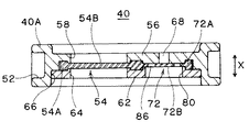
FIG. 1 is a longitudinal sectional view of a liquid-filled
第2取付具14は、第1取付具12の軸心部上方に配されたボス金具であり、径方向外方に向けてフランジ状に突出するストッパ部18が形成されている。また、上端部にはボルト穴20が設けられ、不図示のボルトを介してエンジン側に取り付けられるよう構成されている。
The
第1取付具12は、防振基体16が加硫成形される円筒状の筒状金具22とカップ状の底金具24とからなり、底金具24の中央部に下向きの取付ボルト26が突設され、このボルト26を介して車体側に取り付けられるように構成されている。筒状金具22は、その下端部が底金具24の上端開口部に対し、かしめ部28によりかしめ固定されている。符号30は、筒状金具22の上端部にかしめ固定されたストッパ金具であり、第2取付具14のストッパ部18との間でストッパ作用を発揮する。また、符号32は、ストッパ金具30の上面を覆うストッパゴムである。
The
防振基体16は円錐台形状に形成され、その上端部が第2取付具14に、下端部が筒状金具22の上端開口部にそれぞれ加硫接着されている。この防振基体16の下端部に、筒状金具22の内周面を覆うゴム膜状のシール壁部34が連なっている。
The
第1取付具12には、防振基体16の下面に対して軸方向Xに対向配置されて当該下面との間に液体封入室36を形成する可撓性ゴム膜からなる第1ダイヤフラム38が取り付けられ、液体封入室36に水やエチレングリコール、シリコーンオイル等の液体が封入されている。第1ダイヤフラム38は、外周部に環状の補強金具39を備え、該補強金具39を介して上記かしめ部28に固定されている。
The
第1取付具12の内側に設けられた上記液体封入室36は、仕切り体40により、防振基体16側(即ち、上側)の主液室42と、第1ダイヤフラム38側(即ち、下側)の副液室44とに仕切られている。主液室42は、防振基体16が室壁の一部をなす液室であり、副液室44は、第1ダイヤフラム38が室壁の一部をなす液室である。第1ダイヤフラム38の下側には、底金具24の内側に空気室46が設けられており、従って、第1ダイヤフラム38は、副液室44と空気室46との隔壁をなすダイヤフラムである。
The
仕切り体40は、平面視円形状をなして筒状金具22の内側にシール壁部34を介して嵌着されており、樹脂や金属等の剛性材料からなる。仕切り体40の下面には、リング板状の仕切り受板48が当接配置されており、仕切り受板48を第1ダイヤフラム38の補強金具39とともに、上記かしめ部28で固定することにより、仕切り体40は、シール壁部34に設けられた段部34Aと仕切り受板48との間で軸方向Xに挟まれた状態に保持されている。
The
仕切り体40には、絞り流路である第1オリフィス流路50が設けられており、主液室42と副液室44は該第1オリフィス流路50を介して互いに連通されている。第1オリフィス流路50は、この例では車両走行時のシェイク振動を減衰するために、シェイク振動に対応した低周波数域(例えば、5〜15Hz程度)にチューニングされた低周波側オリフィスである。すなわち、第1オリフィス流路50を通じて流動する液体の共振作用に基づく減衰効果がシェイク振動の入力時に有効に発揮されるように、流路の断面積及び長さを調整することによってチューニングされている。
The
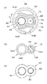
第1オリフィス流路50は、仕切り体40の外周側に設けられている。詳細には、仕切り体40の外周部40Aに設けられた外向きに開かれた第1オリフィス形成溝52(図2参照)と、上記シール壁部34との間で、周方向C(図3(a)参照)に延びる第1オリフィス流路50が形成されている。第1オリフィス通路50は、図3(a)に示すように、周方向Cの一端に、主液室42に対して開口する主液室側開口50Aを備えるとともに、周方向Cの他端に、副液室44に対して開口する副液室側開口50Bを備え、主液室42と副液室44の双方に対して常時閉塞されることなく連通している常時連通状態のオリフィス流路である。
The
仕切り体40には、また、主液室42の圧力緩和を目的として、ゴム膜からなる弾性メンブレン54が設けられている。弾性メンブレン54は、仕切り体40の内周側(即ち、上記外周部40Aよりも径方向内側の仕切り体部分)において主液室42と副液室44を仕切り構成している。
The
弾性メンブレン54は、円板状(円形膜状)をなして、外周部54Aが全周にわたって厚肉状をなすとともに、その内側に外周部54Aよりも薄肉の可撓性部分54Bを備えてなる。この例では、図2及び図3(b)に示すように、弾性メンブレン54は、後述する第2ダイヤフラム72と一体に設けられている。
The
弾性メンブレン54は、外周部54Aが全周にわたって仕切り体40に液密に保持されるとともに、外周部54Aよりも内側の可撓性部分54Bにおいて、一方の膜面(上側の面)に対して主液室42の圧力が及ぼされ、かつ他方の膜面(下側の面)に対して副液室44の圧力が及ぼされるように構成されている。
In the
そのため、弾性メンブレン54を保持する仕切り体本体56には、可撓性部分54Bに対応して主液室42側に開口する開口部58が設けられ、その周りには外周部54Aが配される環状溝60が設けられている。また、この仕切り体本体56との間で弾性メンブレン54を挟持固定するための固定部材62を備える。固定部材62は、樹脂や金属等の剛性材料からなり、可撓性部分54Bに対応して副液室44側に開口する開口部64を有する。固定部材62は、仕切り体本体56の環状溝60の周りに設けられた段部66に対して内嵌固定され、これにより、該環状溝60との間で弾性メンブレン54の外周部54Aを軸方向Xに圧縮した状態に挟持するよう構成されている。
Therefore, the
なお、この例では、弾性メンブレン54の上下両側には、弾性メンブレン54の過大な変位を制限する変位規制部材は設けられてない。
In this example, no displacement restricting members for restricting excessive displacement of the
仕切り体40には、また、絞り流路である第2オリフィス流路68が設けられており、主液室42と副液室44は該第2オリフィス流路68を介して互いに連通されている。第2オリフィス流路68は、第1オリフィス流路50よりも高周波数域にチューニングされた高周波側オリフィスであり、この例ではアイドル時(車両停止時)のアイドル振動を低減するために、アイドル振動に対応した高周波数域(例えば、15〜50Hz程度)にチューニングされている。すなわち、第2オリフィス流路54を通じて流動する液体の共振作用に基づく低動ばね効果がアイドル振動の入力時に有効に発揮されるように、流路の断面積及び長さを調整することによってチューニングされている。
The
図2に示すように、第2オリフィス流路68は、仕切り体40の内周側(即ち、上記外周部40Aよりも径方向内側の仕切り体部分)において、仕切り体40の厚み方向(この例では上記軸方向Xと同じ。)に延びて当該仕切り体40を貫通するように設けられている。詳細には、仕切り体本体56の下面には、平面視円形の段付き凹部70が設けられており(図3(a)参照)、この段付き凹部70の中央部に円形の貫通孔を設けることにより第2オリフィス流路68が形成されている。
As shown in FIG. 2, the
仕切り体40の段付き凹部70には、第2オリフィス流路68の副液室44側の開口68Aに、可撓性ゴム膜からなる第2ダイヤフラム72が設けられている。第2ダイヤフラム72は、図4に示すように、外周部72Aが仕切り体40に対して全周にわたって液密に保持されるとともに、外周部72Aよりも内側の可撓性膜部72Bで上記開口68Aを副液室44側から塞ぐように当該開口周縁部に当接させて設けられている。
In the stepped
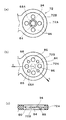
詳細には、第2ダイヤフラム72は、図6に示すように円板状(円形膜状)をなし、外周部72Aが全周にわたって厚肉状をなすとともに、該厚肉の外周部72Aの内側に円形の薄肉膜状をなす可撓性膜部72Bを備えてなる。可撓性膜部72Bは、外周部72Aの厚み方向における中間位置において、当該外周部72Aの内周面間を塞ぐように形成されている。
Specifically, as shown in FIG. 6, the
この例では、第2ダイヤフラム72は、上記弾性メンブレン54と一体に成形されている。詳細には、両者の外周部72A,54A同士で連結させた形状にて一体化されており、従って、図3(b)に示すように、厚肉状の外周部は全体として8の字状をなしている。図2に示すように、第2ダイヤフラム72の可撓性膜部72Bは、弾性メンブレン54の可撓性部分54Bよりも薄肉に形成されている。
In this example, the
また、仕切り体40の段付き凹部70には、第2ダイヤフラム72の外周部72Aが配される環状溝74が設けられ、その内側に第2ダイヤフラム72の可撓性膜部72Bが当接配置される上面が平坦で円形の隆起部76が設けられている。この例では、第2ダイヤフラム72が弾性メンブレン54と一体に設けられているため、外周部72Aを受け入れる環状溝74が、弾性メンブレン54の外周部54Aを受け入れる環状溝60と連結された8の字状に形成されている(図3(a)参照)。また、環状溝74の周りに設けられた段部78も、弾性メンブレン54のための環状溝60の周りに設けた段部66と連結されて設けられている。
Further, the stepped
段付き凹部70に配置された第2ダイヤフラム72は、上記固定部材62により、仕切り体本体56に対して挟持固定されている。すなわち、固定部材62は、弾性メンブレン54だけでなく、第2ダイヤフラム72に対しても固定手段となっている。そのため、上記環状溝74の周りの段部78に対しても内嵌固定され、該環状溝74との間で第2ダイヤフラム72の外周部72Aを軸方向Xに圧縮した状態に挟持することで、当該外周部72Aを液密に(即ち、液体がリークしないように)保持する。
The
固定部材62は、図3(c)に示すように、可撓性膜部72Bに対応した円形の開口部80を有しており、そのため、可撓性膜部72Bの下方(副液室44側)には、可撓性膜部72Bの撓み変形を制限する壁部は存在しない。また、この開口部80の周縁部には、主液室42側に突出して可撓性膜部72Bの外周縁を押圧するリング状突起82が設けられており、第2ダイヤフラム72の外周部72Aの内周面に当接して当該外周部72Aの内方への変位を規制している(図4参照)。
As shown in FIG. 3C, the fixing
このようにして仕切り体40に組み込まれた第2ダイヤフラム72は、可撓性膜部72Bが段付き凹部70の隆起部76の下面に押し付けられており、これにより第2オリフィス流路68の上記開口68Aを塞いでいる。可撓性膜部72Bは、その径方向中央部で上記開口68Aを塞いでおり、そのため、該開口68Aを塞ぐ径方向中央部が栓部分84となっている。
In the
可撓性膜部72Bは、第2オリフィス流路68の上記開口68Aに対して重ならない位置、即ち軸方向Xからみてラップしないように、少なくとも1つの貫通穴86を備える。貫通穴86は、可撓性膜部72Bの中央に位置する上記栓部分84を取り囲む円周上の複数箇所に並設されており、この例では、等間隔にて4個の円形の貫通穴86が設けられている。
The
以上よりなる液封入式防振装置10であると、主液室42の液圧の絶対値が規定値以下であるような通常使用領域においては、第2ダイヤフラム72の可撓性膜部72Bが第2オリフィス流路68の上記開口68Aに当接して当該開口68Aを塞いでいる。そのため、通常使用領域ではこの部分からの液体のリークを防止することができる。一方、主液室42の液圧が規定値よりも大きくなり、第2オリフィス流路68の流量が所定量以上となったときには、図5に示すように、外周部72Aが保持された第2ダイヤフラム72は、その内側の可撓性膜部72Bが、液流動によって副液室44側に押圧されることで、第2オリフィス流路68の開口68Aから副液室44側(即ち、下方)に離間するように撓み変形する。これにより、主液室42内の液体を可撓性膜部72Bに設けられた貫通穴86を通して副液室44側に逃がすことができる。なお、副液室44から第2オリフィス流路68への液体の流入は第2ダイヤフラム72によって阻止されるので、可撓性膜部72Bは逆止弁として機能する。
In the liquid-filled
従って、上記液封入式防振装置10であると、通常使用領域において、車両走行時にシェイク振動のように比較的大振幅で低周波数側の振動が入力した時には、第2ダイヤフラム72での液体のリークを防止しつつ、低周波数側の第1オリフィス流路50を介して液体が主液室42と副液室44の間を行き来するので、第1オリフィス流路50を流動する液体の共振作用に基づき、シェイク振動に対して高い減衰性能が発揮される。
Therefore, with the liquid-filled
また、停車したアイドル時のように比較的微振幅で高周波数側の振動が入力した時には、第2ダイヤフラム72が第2オリフィス流路68の上記開口68Aに対する閉塞状態を維持しつつ微小振幅にて撓み変形することにより、高周波数側の第2オリフィス流路68で液体の流動が起こり、かかる高周波側の第2オリフィス流路68を通じての液体の共振作用により、アイドル振動に対する優れた防振効果が発揮される。
Further, when vibration on the high frequency side is input with a relatively small amplitude, such as during idling when the vehicle is stopped, the
また、かかる通常使用領域において、仕切り体40に設けた弾性メンブレン54が主液室42と副液室44間の圧力変動に基づいて撓み変形することにより、主液室42内の圧力を緩和して、例えば、アイドル振動よりも高周波数域であるこもり音領域での動ばね定数を低減することができる。
Further, in such a normal use region, the
一方、路面の段差を乗り越えるなどして大振幅の入力が生じ、第2オリフィス流路68の流量が所定量以上に達したときには、第2ダイヤフラム72の可撓性膜部72Bが第2オリフィス流路68の開口68Aから副液室44側に離間するように撓み変形する。これにより、可撓性膜部72Bに設けられた貫通穴86から副液室44側に液体が供給されるので、主液室42内の過度な正圧発生に対する圧力緩和を行うことができる。そのため、弾性メンブレン54の過度な撓み変形を抑制することができる。
On the other hand, when a large-amplitude input is generated, such as over a road surface step, and the flow rate of the second
このように本実施形態の防振装置10であると、通常使用領域では第2オリフィス流路68での液体流動を生じさせるダイヤフラムとしての役割を持つ第2ダイヤフラム72を、第2オリフィス流路68の流量が所定量に達したときにおける圧力緩和を行うための弁として利用している。そのため、部品点数の削減や構造の簡略化が図られ、低コスト化に繋がる。
As described above, in the
また、主液室42の過大な正圧発生を抑えることができるので、弾性メンブレン54については、もはや過大な正圧発生に耐え得る設計を行う必要がなくなる。そのため、耐久性を損なうことなく、弾性メンブレン54の低剛性化が可能となり、低動ばね特性を容易に実現することができる。
In addition, since the generation of excessive positive pressure in the main
なお、上記第2ダイヤフラム72は、その離間後において、第2オリフィス流路68の流量が所定量以下に達したときには、第2オリフィス流路68の開口68Aに再び当接するが、その復帰力はゴム弾性によるものであり、復帰に伴う衝撃は小さいので、復帰に伴う異音が発生しにくい。
When the flow rate of the
また、本実施形態によれば、第2ダイヤフラム72の可撓性膜部72Bが、径方向中央部を栓部分84とし、その径方向外方に貫通穴86を設けたので、第2ダイヤフラム72が撓み変形したときに、第2オリフィス流路68の開口68Aと栓部材84との間隔を大きく確保でき、副液室44側への液体の供給をよりスムースにすることができる。
Further, according to the present embodiment, the
[第2の実施形態]
図7,8は、第2の実施形態の液封入式防振装置に関する図である。この例では、第2ダイヤフラム72の可撓性膜部72Bに突起88を設けた点で上記実施形態とは異なる。
[Second Embodiment]
7 and 8 are diagrams related to the liquid-filled vibration isolator of the second embodiment. This example differs from the above embodiment in that a
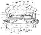
詳細には、図7に示すように、第2ダイヤフラム72の副液室44側には、可撓性膜部72Bの副液室44側の膜面と間隔Lをあけて対向する対向壁90が設けられている。対向壁90は、固定部材62に一体に設けられている。従って、この例では、固定部材66は、可撓性膜部72Bに対応した対向壁90を有して、その中央部に副液室44と第2オリフィス流路68側を連通させる連通穴92が設けられるとともに、対向壁78の外周に上記リング状突起82が設けられ、更にその外周側で第2ダイヤフラム72の外周部72Aを挟持するように構成されている。
Specifically, as shown in FIG. 7, the opposing
また、可撓性膜部72Bには、第2オリフィス流路68の上記開口68Aに対して重ならない位置における副液室44側の膜面に、上記対向壁90との間で圧縮される突起88が設けられている。この例では、突起88は、仕切り体40に組み込んだ状態で対向壁90に押し付けられて圧縮されるように構成されている。
Further, the
突起88は、副液室44側の膜面のみに設けられており、図8に示すように、錐体状、この例では円錐状をなし、上記貫通穴86と同じ円周上の複数箇所(この例では4箇所)において、貫通穴86と交互に設けられている。
The
このように可撓性膜部72Bの副液室44側に設けた突起88を対向壁90との間で圧縮させることで、第2ダイヤフラム72の剛性を変化させることができるので、第2オリフィス流路68の開口68Aから離間するタイミングを容易に調整することができる。
In this way, the rigidity of the
詳細には、高周波側の第2オリフィス流路68の特性を向上するためには、第2オリフィス流路68の開口68Aを塞ぐ膜部分(上記栓部分84)の剛性を小さくして、微小変形しやすくすることが求められるが、そのために単にゴム硬度を小さくすると、大振幅入力時に第2ダイヤフラム72が撓み変形しやすくなって第2オリフィス流路68の開口68Aから早期に離間してしまうので、第1オリフィス流路50による本来の減衰性能が損なわれるおそれがある。これに対し、上記突起88を設けておけば、ゴム硬度を小さくして中央部の栓部分84を微小変形しやすいものとしつつ、その周縁部は突起88の圧縮によって剛性を高めて、第2オリフィス流路68の開口68Aから離間するタイミングを遅らせることができる。また、このようにゴム硬度を小さくすることができれば、第2ダイヤフラム72の復帰時における衝撃を抑えることもでき、異音を発生しにくくすることができる。
Specifically, in order to improve the characteristics of the second
また、本実施形態のように、複数の突起88を貫通穴86と周上で交互に設けることにより、撓み変形に対する第2ダイヤフラム72の剛性を周上で均一化することができ、第2オリフィス流路68の開口68Aから離間するタイミングの調整が更に容易となる。その他の構成及び作用効果は第1の実施形態と同様であり、説明は省略する。
Further, by providing the plurality of
[第3の実施形態]
図9は、第3の実施形態の液封入式防振装置に関する図である。この例では、第2ダイヤフラム72の可撓性膜部72Bに環状突起94を設けた点で上記第2の実施形態とは異なる。
[Third Embodiment]
FIG. 9 is a diagram relating to the liquid-filled vibration isolator of the third embodiment. This example differs from the second embodiment in that an
すなわち、この例では、第2オリフィス流路68の上記開口68Aの周縁部に対向する可撓性膜部72Bの主液室42側の膜面に、該開口68Aを取り囲むように全周にわたって延びる環状突起94が設けられている。環状突起94は、可撓性膜部72Bの中央部に相当する栓部分84の外周部に沿って平面視円形状に設けられており、上記貫通穴86及び突起88よりも径方向内側に設けられている。
That is, in this example, the film surface on the main
かかる環状突起94は、第2ダイヤフラム72を第2オリフィス流路68の開口68Aに当接させたときに、当該開口周りをシールするシール突条として機能する。そのため、第2オリフィス流路68の流量が所定量に達するまでにおける第2オリフィス流路68での液体流動に対して、第2ダイヤフラム72と第2オリフィス流路68の開口68Aとの間での液密性をより確実にすることができる。その他の構成及び作用効果は第2の実施形態と同様であり、説明は省略する。
When the
[第4の実施形態]
図10は、第4の実施形態の液封入式防振装置に関する図である。この例では、弾性メンブレン54と第2ダイヤフラム72を別体に設けた点で上記第1実施形態とは異なる。
[Fourth Embodiment]
FIG. 10 is a diagram relating to the liquid-filled vibration isolator of the fourth embodiment. This example differs from the first embodiment in that the
すなわち、この例では、弾性メンブレン54と第2ダイヤフラム72は、それぞれ別部材として円形状に形成されており、両部材54,72が仕切り体本体56の下面側の凹部にそれぞれ装着されて、共通の固定部材62で固定されている。
That is, in this example, the
このように弾性メンブレン54と第2ダイヤフラム72は別体に設けてもよいが、部品点数の削減と組み付け作業性の点では、上記実施形態のように両者を一体に成形することが好ましい。その他の構成及び作用効果は第1の実施形態と同様であり、説明は省略する。
As described above, the
[その他の実施形態]
第2ダイヤフラム72に設けた貫通穴86や突起88の配置や数、形状は、上記実施形態に限定されるものではなく、種々の変更が可能である。例えば、上記実施形態では、可撓性膜部72Bの中央部を、第2オリフィス流路68の開口68Aを塞ぐ栓部分84とし、その周りに貫通穴86を複数設けたが、上記開口68Aを可撓性膜部72Bの中心に対して一方側に偏心させて設け、他方側に貫通穴86を設けてもよい。
[Other Embodiments]
The arrangement, number, and shape of the through
また、上記実施形態では、環状突起94を第2ダイヤフラム72の可撓性膜部72Bに設けたが、かかる環状突起は仕切り体40側に設けることもできる。すなわち、第2オリフィス流路68の上記開口68Aの周縁部に、当該開口68Aを取り囲むように、第2ダイヤフラム72側に突出する環状突起を設けてもよい。
Moreover, in the said embodiment, although the
また、上記実施形態では、液室として主液室42と単一の副液室44とからなる場合について説明したが、主液室とともに複数の副液室を持ち、これらの液室間がオリフィス流路で連結された様々な液封入式防振装置にも同様に適用することもできる。その場合、第1オリフィス流路を介して主液室と連通される副液室と、第2オリフィス流路を介して主液室と連通される副液室とは同一でも異なってもよい。また、副液室同士を連通させる他のオリフィス流路を備えるものであってもよい。
In the above embodiment, the case where the liquid chamber includes the main
好ましくは、上記実施形態のように、空気室46に面した第1ダイヤフラム38を室壁の一部とする副液室44と主液室42との間を連結する第2オリフィス流路68において、上記第2ダイヤフラム72による弁構成を組み込むことである。空気室46に面した第1ダイヤフラム38を室壁の一部とする副液室44は、主液室42との間での圧力差が大きいので、第2オリフィス流路68の流量が大きくなりやすく、そのため、上記第2ダイヤフラム72による圧力緩和効果を高めることができる。なお、この場合も、第1オリフィス流路を介して主液室と連結される副液室は、第2オリフィス流路を介して主液室と連結される副液室とは同一でも異なってもよい。また、第1ダイヤフラム38としては、空気室46の代わりに外気に面したものであってもよい。
Preferably, as in the above-described embodiment, in the
上記実施形態では、また、シェイク振動とアイドル振動を対象としたが、これに限らず、周波数の異なる種々の振動に対して適用することができる。その他、一々列挙しないが、本発明の趣旨を逸脱しない限り、種々の変更が可能である。 In the above embodiment, the shake vibration and the idle vibration are targeted. However, the present invention is not limited to this, and can be applied to various vibrations having different frequencies. Although not enumerated one by one, various modifications can be made without departing from the spirit of the present invention.
本発明は、エンジンマウントの他、例えば、モータなど他のパワーユニットを支承するマウント、ボディマウント、デフマウントなど、種々の防振装置に利用することができる。 The present invention can be used for various vibration isolators such as a mount that supports other power units such as a motor, a body mount, and a differential mount, in addition to an engine mount.
10…液封入式防振装置、 12…第1取付具、 14…第2取付具、
16…防振基体、 36…液体封入室、 38…第1ダイヤフラム、
40…仕切り体、 40A…仕切り体の外周部、 42…主液室、
44…副液室、 46…空気室、 50…第1オリフィス流路、
54…弾性メンブレン、 68…第2オリフィス流路、 68A…副液室側の開口、
72…第2ダイヤフラム、 72A…外周部、 72B…可撓性膜部、
84…栓部分、 86…貫通穴、 88…突起、
90…対向壁、 94…環状突起、
X…軸方向、 C…周方向、 L…間隔
DESCRIPTION OF
16 ... Vibration-proof substrate, 36 ... Liquid enclosure, 38 ... First diaphragm,
40 ... partition body, 40A ... outer periphery of partition body, 42 ... main liquid chamber,
44 ... Secondary liquid chamber, 46 ... Air chamber, 50 ... First orifice channel,
54 ... elastic membrane, 68 ... second orifice channel, 68A ... opening on the secondary liquid chamber side,
72 ... 2nd diaphragm, 72A ... Outer peripheral part, 72B ... Flexible membrane part,
84 ... plug part, 86 ... through hole, 88 ... projection,
90 ... opposing wall, 94 ... annular projection,
X: axial direction, C: circumferential direction, L: spacing
Claims (8)
振動源側と支持側の他方に取り付けられる第2取付具と、
前記第1取付具と第2取付具との間に介設されたゴム状弾性体からなる防振基体と、
前記防振基体が室壁の一部をなす液体が封入された主液室と、
ゴム状弾性膜からなるダイヤフラムが室壁の一部をなす液体が封入された少なくとも1つの副液室と、
前記主液室といずれかの副液室とを連結する第1オリフィス流路と、
を備えた液封入式防振装置において、
前記主液室といずれかの副液室とを仕切る仕切り体に、当該副液室と主液室を仕切るゴム状弾性体からなる弾性メンブレンと、当該副液室と主液室とを連結して前記第1オリフィス流路よりも高周波数域にチューニングされた第2オリフィス流路とが設けられるとともに、前記第2オリフィス流路の副液室側への開口にゴム状弾性膜からなる第2ダイヤフラムが設けられ、
前記第2ダイヤフラムは、外周部が前記仕切り体に対して液密に保持されるとともに、前記外周部よりも内側の可撓性膜部で前記開口を塞ぐように当該開口周縁部に当接させて設けられ、前記可撓性膜部には前記開口に対して重ならない位置に貫通穴が設けられた
ことを特徴とする液封入式防振装置。 A first fixture attached to one of the vibration source side and the support side;
A second fixture attached to the other of the vibration source side and the support side;
An anti-vibration base made of a rubber-like elastic body interposed between the first fixture and the second fixture;
A main liquid chamber in which a liquid in which the vibration isolating substrate forms a part of a chamber wall is enclosed;
At least one sub-liquid chamber in which a liquid in which a diaphragm made of a rubber-like elastic film forms part of the chamber wall is enclosed;
A first orifice channel connecting the main liquid chamber and any one of the sub liquid chambers;
In a liquid-filled vibration isolator equipped with
An elastic membrane made of a rubber-like elastic body that partitions the sub-liquid chamber and the main liquid chamber, and the sub-liquid chamber and the main liquid chamber are connected to a partition that partitions the main liquid chamber and any sub-liquid chamber. And a second orifice channel tuned to a higher frequency range than the first orifice channel, and a second elastic channel formed of a rubber-like elastic film at the opening of the second orifice channel toward the sub liquid chamber side. A diaphragm is provided,
The second diaphragm is held in contact with the peripheral edge of the opening so that the outer peripheral portion is liquid-tight with respect to the partition body and the opening is closed by a flexible film portion inside the outer peripheral portion. A liquid-filled type vibration damping device, wherein the flexible film portion is provided with a through hole at a position that does not overlap the opening.
Priority Applications (1)
| Application Number | Priority Date | Filing Date | Title |
|---|---|---|---|
| JP2010011218A JP5431982B2 (en) | 2010-01-21 | 2010-01-21 | Liquid-filled vibration isolator |
Applications Claiming Priority (1)
| Application Number | Priority Date | Filing Date | Title |
|---|---|---|---|
| JP2010011218A JP5431982B2 (en) | 2010-01-21 | 2010-01-21 | Liquid-filled vibration isolator |
Publications (2)
| Publication Number | Publication Date |
|---|---|
| JP2011149493A JP2011149493A (en) | 2011-08-04 |
| JP5431982B2 true JP5431982B2 (en) | 2014-03-05 |
Family
ID=44536651
Family Applications (1)
| Application Number | Title | Priority Date | Filing Date |
|---|---|---|---|
| JP2010011218A Expired - Fee Related JP5431982B2 (en) | 2010-01-21 | 2010-01-21 | Liquid-filled vibration isolator |
Country Status (1)
| Country | Link |
|---|---|
| JP (1) | JP5431982B2 (en) |
Families Citing this family (6)
| Publication number | Priority date | Publication date | Assignee | Title |
|---|---|---|---|---|
| JP5969249B2 (en) * | 2012-03-31 | 2016-08-17 | 山下ゴム株式会社 | Liquid seal vibration isolator |
| JP5882124B2 (en) * | 2012-04-24 | 2016-03-09 | 東洋ゴム工業株式会社 | Liquid-filled vibration isolator |
| JP5882125B2 (en) * | 2012-04-24 | 2016-03-09 | 東洋ゴム工業株式会社 | Liquid-filled vibration isolator |
| DE102014223403A1 (en) * | 2014-11-17 | 2016-05-19 | Contitech Vibration Control Gmbh | Hydro bearing and motor vehicle with such a hydraulic bearing |
| JP6975628B2 (en) * | 2017-12-04 | 2021-12-01 | 株式会社ブリヂストン | Anti-vibration device |
| WO2024009712A1 (en) * | 2022-07-05 | 2024-01-11 | 株式会社村田製作所 | Pressure sensor device |
Family Cites Families (4)
| Publication number | Priority date | Publication date | Assignee | Title |
|---|---|---|---|---|
| JP2004301245A (en) * | 2003-03-31 | 2004-10-28 | Tokai Rubber Ind Ltd | Liquid enclosed type damping device |
| JP4919783B2 (en) * | 2006-12-05 | 2012-04-18 | 山下ゴム株式会社 | Liquid seal vibration isolator |
| JP2009103141A (en) * | 2007-10-19 | 2009-05-14 | Toyota Motor Corp | Liquid filling type vibration-proof device |
| JP4871908B2 (en) * | 2008-04-25 | 2012-02-08 | 東海ゴム工業株式会社 | Fluid filled vibration isolator |
-
2010
- 2010-01-21 JP JP2010011218A patent/JP5431982B2/en not_active Expired - Fee Related
Also Published As
| Publication number | Publication date |
|---|---|
| JP2011149493A (en) | 2011-08-04 |
Similar Documents
| Publication | Publication Date | Title |
|---|---|---|
| JP5095763B2 (en) | Liquid-filled vibration isolator | |
| JP5248645B2 (en) | Liquid-filled vibration isolator | |
| JP5882125B2 (en) | Liquid-filled vibration isolator | |
| JP4820792B2 (en) | Fluid filled vibration isolator | |
| JP4842086B2 (en) | Fluid filled vibration isolator | |
| JP5535958B2 (en) | Liquid-filled vibration isolator | |
| JP5431982B2 (en) | Liquid-filled vibration isolator | |
| JP5882124B2 (en) | Liquid-filled vibration isolator | |
| JP5184276B2 (en) | Liquid-filled vibration isolator | |
| JP2003139189A (en) | Fluid sealing type vibration isolation device | |
| JP4158110B2 (en) | Pneumatic switching type fluid-filled engine mount | |
| JP5184272B2 (en) | Liquid-filled vibration isolator | |
| JP5510713B2 (en) | Liquid-filled vibration isolator | |
| JP4871902B2 (en) | Fluid filled vibration isolator | |
| JP4158111B2 (en) | Pneumatic switching type fluid-filled engine mount | |
| JP5893482B2 (en) | Liquid-filled vibration isolator | |
| JP5690988B2 (en) | Liquid-filled vibration isolator | |
| JP7301713B2 (en) | Fluid-filled anti-vibration device | |
| JP5014239B2 (en) | Fluid filled vibration isolator | |
| JP5386289B2 (en) | Fluid filled vibration isolator | |
| JP5122523B2 (en) | Liquid-filled vibration isolator | |
| JP5468513B2 (en) | Liquid-filled vibration isolator | |
| JP5476635B2 (en) | Liquid-filled vibration isolator | |
| JP2018091397A (en) | Fluid-sealed type vibration control device | |
| JP2014190346A (en) | Fluid sealed vibration isolator |
Legal Events
| Date | Code | Title | Description |
|---|---|---|---|
| A621 | Written request for application examination |
Free format text: JAPANESE INTERMEDIATE CODE: A621 Effective date: 20130110 |
|
| A977 | Report on retrieval |
Free format text: JAPANESE INTERMEDIATE CODE: A971007 Effective date: 20131025 |
|
| TRDD | Decision of grant or rejection written | ||
| A01 | Written decision to grant a patent or to grant a registration (utility model) |
Free format text: JAPANESE INTERMEDIATE CODE: A01 Effective date: 20131126 |
|
| A61 | First payment of annual fees (during grant procedure) |
Free format text: JAPANESE INTERMEDIATE CODE: A61 Effective date: 20131205 |
|
| R150 | Certificate of patent or registration of utility model |
Free format text: JAPANESE INTERMEDIATE CODE: R150 Ref document number: 5431982 Country of ref document: JP Free format text: JAPANESE INTERMEDIATE CODE: R150 |
|
| R250 | Receipt of annual fees |
Free format text: JAPANESE INTERMEDIATE CODE: R250 |
|
| S531 | Written request for registration of change of domicile |
Free format text: JAPANESE INTERMEDIATE CODE: R313531 |
|
| R350 | Written notification of registration of transfer |
Free format text: JAPANESE INTERMEDIATE CODE: R350 |
|
| R250 | Receipt of annual fees |
Free format text: JAPANESE INTERMEDIATE CODE: R250 |
|
| LAPS | Cancellation because of no payment of annual fees |