JP5111970B2 - Method and apparatus for producing preformed resin - Google Patents
Method and apparatus for producing preformed resin Download PDFInfo
- Publication number
- JP5111970B2 JP5111970B2 JP2007200697A JP2007200697A JP5111970B2 JP 5111970 B2 JP5111970 B2 JP 5111970B2 JP 2007200697 A JP2007200697 A JP 2007200697A JP 2007200697 A JP2007200697 A JP 2007200697A JP 5111970 B2 JP5111970 B2 JP 5111970B2
- Authority
- JP
- Japan
- Prior art keywords
- resin
- film
- preformed
- powdery
- heating
- Prior art date
- Legal status (The legal status is an assumption and is not a legal conclusion. Google has not performed a legal analysis and makes no representation as to the accuracy of the status listed.)
- Active
Links
Images


Landscapes
- Processing And Handling Of Plastics And Other Materials For Molding In General (AREA)
- Casting Or Compression Moulding Of Plastics Or The Like (AREA)
Description
本発明は、半導体チップ等を搭載した基板を樹脂にて圧縮封止する樹脂封止装置の技術分野に関する。 The present invention relates to a technical field of a resin sealing device that compresses and seals a substrate on which a semiconductor chip or the like is mounted with resin.
近年、半導体チップ等の製品を樹脂にて封止する装置として、いわゆる圧縮型の樹脂封止装置に対する需要が高まっている。このような圧縮型の樹脂封止装置として、特許文献1に示される樹脂封止装置が公知である。特許文献1に記載されている樹脂封止装置は、上型と下型とからなる圧縮成形金型を備えている。また、この下型にはプレスが連結されており、所定のタイミングで下型を上型に対して当接、離間することが可能とされている。下型は、貫通孔を備えた枠状金型と当該貫通孔に嵌合して配置される圧縮金型とを有した構成とされ、下型の対向面(上型側表面)の一部に形成されるキャビティにおいて被成形品を樹脂にて圧縮封止する。 In recent years, as a device for sealing a product such as a semiconductor chip with a resin, a demand for a so-called compression type resin sealing device is increasing. As such a compression type resin sealing device, a resin sealing device disclosed in Patent Document 1 is known. The resin sealing device described in Patent Document 1 includes a compression mold including an upper mold and a lower mold. Further, a press is connected to the lower mold, and the lower mold can be brought into contact with and separated from the upper mold at a predetermined timing. The lower mold is configured to include a frame-shaped mold having a through hole and a compression mold that is fitted and disposed in the through hole, and a part of an opposing surface (upper mold side surface) of the lower mold The molded product is compression-sealed with resin in the cavity formed in the above.
このような圧縮成形金型を備える樹脂封止装置においては、圧縮成形金型への投入に先立ち、予め粉状若しくは粒状の樹脂をキャビティの形状に合わせて予備成形(プレ成形、打錠)した上で投入する手法を採ることがある。これは、投入する樹脂を予めキャビティの形状に合わせることで圧縮時の樹脂の流動を最小限に抑える目的がある。また、樹脂が粉状や粒状のままでは熱が内部まで伝達され難い場合や伝達むらが生じる場合があるが、予備成形を行うことで熱の伝達を均一化し、樹脂封止時において全体として素早く樹脂を溶融させることが可能となる等の理由によるものである。 In a resin sealing device equipped with such a compression molding die, prior to charging into the compression molding die, a powdery or granular resin is preliminarily molded (pre-molding, tableting) according to the shape of the cavity. The above approach may be taken. The purpose of this is to minimize the flow of the resin during compression by matching the shape of the resin to be added in advance with the shape of the cavity. In addition, if the resin is in powder or granular form, heat may not be transferred to the inside or unevenness may occur.However, pre-molding makes the heat transfer uniform and quick as a whole when sealing the resin. This is because the resin can be melted.
このような予備成形を行う装置、方法が特許文献2に示されている。この特許文献2に示される装置を概略的に図10に示すと共に、構成および作用について間単に説明する。 An apparatus and a method for performing such preforming are disclosed in Patent Document 2. The apparatus shown in Patent Document 2 is schematically shown in FIG. 10, and the configuration and operation will be briefly described.
プレ成形部200は、樹脂供給機構100から供給された樹脂300を、樹脂封止装置(図示しない)のキャビティの形状に合わせて予め予備成形することを目的としている。プレ成形部200は、ヒータ(図示しない)が備わった打錠プレス202と、当該打錠プレス202に隣接して配置される冷却部204とから構成される。また、第1ローラ208A、第2ローラ208Bおよび駆動ローラ210にはフィルム206が係合している。この駆動ローラ210は、自身が水平方向(図10において左右方向)に移動可能とされている。その結果、駆動ローラ210は、型開きした状態の打錠プレス202と冷却部204の間に進入することが可能とされている。
The pre-molding unit 200 is intended to preform in advance the
図10(A)に示すように、樹脂供給機構100からシュータ112を介して粉状または粒状の樹脂300がフィルム206上に供給される(この最初にフィルム206上に供給された樹脂300を説明のため第1の樹脂300Aとする。)。その後、駆動ローラ210がプレ成形部200側(図10において右側)に移動する。これにより、図10(B)に示すように、第1の樹脂300Aが、打錠プレス202の位置にまで移動し、打錠プレス202により所定の形状(例えば、樹脂封止装置のキャビティの形状と相似する板状)へと打錠(予備成形)される。また、この間に、樹脂供給機構100から別の樹脂300がフィルム206上に供給される(ここで供給された樹脂300を第2の樹脂300Bとする。)。
As shown in FIG. 10A, a powdery or
その後は図10(C)〜(D)に示すように、フィルム206によって上下に包被されながら第1、第2の樹脂300A、300Bが順次打錠、冷却される。第2の樹脂300Bの冷却が完了すると、図10(E)に示したように、駆動ローラ210が再度水平移動する。その結果、第1、第2の樹脂300A、300Bの上下に位置していたフィルム206の包被が解かれ、取り出し可能となる。その後、図10(E)〜(F)に示すように、搬送機構400によって順次運び出される。その後は図10(A)に戻り、同様の動作が繰り返される。なお、搬送機構によって運び出された予備成形後の樹脂は、樹脂封止装置(圧縮成形金型)への投入に先立って再度確認のため計量(予備成形後計量)された後、金型へと投入される。
Thereafter, as shown in FIGS. 10C to 10D, the first and
近年、圧縮型の樹脂封止装置は、生産性向上の要請を受けマルチプレス化、高速化する状況にある。即ち、樹脂封止装置(圧縮成形金型)が、大量の予備成形樹脂を要求する状況にある。 In recent years, compression-type resin sealing devices have been in a situation of being multi-pressed and speeded up in response to a request for improvement in productivity. That is, the resin sealing device (compression molding die) is in a situation where a large amount of preformed resin is required.
しかしながら、上記説明した手順(特許文献2に記載された手順)では、当該要求に必ずしも応えられるものではなかった。即ち、打錠プレスや冷却部などの各部分に多くの「待機時間」が存在していることによって、当該要求に見合うような「効率よく予備成形樹脂を成形する」ことができていない。具体的に図10を参照しつつ説明すると、例えば、図10(B)の時点においては、冷却部204は、打錠プレス202によって第1の樹脂300Aが打錠されるまでの間、待機状態となっている。また、図10(D)の時点では、冷却部204によって第2の樹脂300Bの冷却が終了するまでの間、打錠プレス202は予備成形樹脂の生産には寄与していない。更にこの何れの時点においても、樹脂供給機構100や搬送機構400は待機状態にある。
However, the above-described procedure (the procedure described in Patent Document 2) cannot always meet the request. That is, since there are many “standby times” in each part such as a tableting press and a cooling unit, it is not possible to “mold a preformed resin efficiently” to meet the requirement. Specifically, referring to FIG. 10, for example, at the time of FIG. 10B, the
一方、このような各部の待機状態を解消し、予備成形樹脂の生産性を向上させるには、図11に示すような方法を採用することも可能である。ここでは、樹脂を包被するフィルム206を上下別々とし、その上下のフィルム206のそれぞれを巻回したフィルム供給ロール210から供給すると同時にフィルム回収ロール211によって巻回して回収している。このようにして連続的に予備成形樹脂を製造すれば、打錠プレス202や冷却部204の待機時間を減らし効率よく予備成形樹脂を製造することは可能となる。しかしこのような手法では、フィルムの再利用ができずにフィルムに要するコストが上昇する。また、上下別々にフィルムをハンドリングしているため、上下のフィルムの同期を取ることが難しく、場合によっては樹脂を包被した後に「ズレ」が生じ、精度の良い予備成形樹脂を製造することが困難である。
On the other hand, a method as shown in FIG. 11 can be adopted to eliminate such standby states of the respective parts and improve the productivity of the preformed resin. Here, the
本発明は、これらの問題点を解決するべくなされたものであって、フィルムの再利用を可能としてフィルムに要するコストの低減を図ると共に、精度のよい予備成形樹脂を効率よく生産することができる予備成形樹脂の製造方法および製造装置を提供するものである。 The present invention has been made to solve these problems, and enables the reuse of the film to reduce the cost required for the film and to efficiently produce an accurate preformed resin. A method and apparatus for producing a preformed resin are provided.
本発明は、圧縮成形金型への投入に先立って、粉状または粒状の樹脂を所定の形状に予備成形する予備成形樹脂の製造方法であって、前記粉状または粒状の樹脂を包被するために所定の形状に切断されたフィルムを支持体に固定するフィルム固定工程と、前記支持体に固定された前記フィルム上に前記粉状または粒状の樹脂を供給する樹脂供給工程と、前記フィルム上に供給された前記粉状または粒状の樹脂を包被する包被工程と、前記包被された状態のままで前記フィルムを介して前記粉状または粒状の樹脂を複数段階に分割された加熱工程を行うことにより所定の形状に予備成形する予備成形工程と、を経て予備成形樹脂を製造することにより、上記課題を解決するものである。 The present invention is a method for producing a preformed resin in which a powdery or granular resin is preformed into a predetermined shape prior to injection into a compression mold, and the powdered or granular resin is encapsulated. A film fixing step for fixing a film cut into a predetermined shape to a support, a resin supply step for supplying the powdery or granular resin onto the film fixed to the support, and the film An encapsulating process for encapsulating the powdered or granular resin supplied to the heating process, and a heating process in which the encapsulated state of the powdered or granular resin is divided into a plurality of stages through the film The above-mentioned problem is solved by manufacturing a preformed resin through a preforming step of preforming into a predetermined shape by performing the above.
このような方法を採用すれば、フィルムの再利用が可能となり、フィルムに要するコストを低減することができる。また、フィルムを支持体に固定しているためフィルムのハンドリングが容易である。更に、フィルムが支持体に固定された状態で樹脂を包被しているので、樹脂を包被するフィルムに「ズレ」が生じる余地を排除しているため、フィルムの同期をとる必要もない。 By adopting such a method, the film can be reused, and the cost required for the film can be reduced. Moreover, since the film is fixed to the support, it is easy to handle the film. Furthermore, since the resin is encapsulated while the film is fixed to the support, there is no need to synchronize the film because there is no room for “deviation” in the film encapsulating the resin.
また、前記予備成形工程が、更に、前記加熱により所定の形状に成形された前記樹脂を冷却する冷却工程と、を含み、かつ、前記支持体が複数用意されることにより、前記フィルム固定工程、樹脂供給工程、包被工程、加熱工程、冷却工程のうち少なくとも2つ以上の工程が同時に進行するような方法を採用することも可能である。 In addition, the preforming step further includes a cooling step of cooling the resin molded into a predetermined shape by the heating, and a plurality of the supports are prepared, whereby the film fixing step, It is also possible to employ a method in which at least two of the resin supply process, the covering process, the heating process, and the cooling process proceed simultaneously.
このような方法を採用すれば、同時に複数の支持体(および当該支持体に固定されたフィルム)を利用して予備成形樹脂を製造することが可能となり、生産効率を向上させることが可能となる。 By adopting such a method, it becomes possible to manufacture a preformed resin using a plurality of supports (and a film fixed to the support) at the same time, and it is possible to improve production efficiency. .
また、前記樹脂供給工程が、最終的な必要量の範囲内で概量を供給する第1の樹脂供給工程と、前記必要量と前記概量との差分を供給する第2の樹脂供給工程と、を含むような方法を採用することも可能である。 The resin supply step includes a first resin supply step for supplying an approximate amount within a final required amount range, and a second resin supply step for supplying a difference between the required amount and the approximate amount. It is also possible to adopt a method including
このように全工程の中で「ボトルネック」となり得る樹脂供給工程を複数段階の工程に分割することで、予備成形樹脂のタクトタイムを向上させることが可能となる。更に、第1の樹脂供給工程にて概量を供給しておき、第2の樹脂供給工程で「差分」を(ボトルネックとならない範囲で)時間を掛けて計量供給することができ、予備成形樹脂の成形精度(樹脂量という観点からの成形精度)を向上させることも可能となる。 Thus, by dividing the resin supply process that can be a “bottleneck” in all processes into a plurality of steps, it is possible to improve the tact time of the preformed resin. Furthermore, an approximate amount can be supplied in the first resin supply step, and "difference" can be metered over time (to the extent that it does not become a bottleneck) in the second resin supply step. It is also possible to improve resin molding accuracy (molding accuracy from the viewpoint of the amount of resin).
また、前記複数段階に分割された加熱工程が、前記粉状または粒状の樹脂を第1の形状に加熱成形する第1の加熱工程と、前記第1の形状とされた前記樹脂を第2の形状に加熱成形する第2の加熱工程と、を含むような方法を採用することも可能である。 In addition, the heating process divided into the plurality of stages includes a first heating process in which the powdery or granular resin is thermoformed into a first shape, and the resin in the first shape is a second It is also possible to employ a method that includes a second heating step of heat forming into a shape.
このように全工程の中で「ボトルネック」となり得る加熱工程を複数段階の工程に分割することで、予備成形樹脂のタクトタイムを向上させることが可能となる。更に、単に複数回に分割して加熱成形するのではなく、段階的に異なる「型」を用いて加熱成形することも可能になる。例えば、第1の加熱工程では中央部にまで熱が伝達するように中央部が凸状に盛り上がった「型」を用いて加熱成形し、その後、全体を万遍なく加熱するように平坦な「型」を用いて加熱成形するといったことも可能となる。 Thus, by dividing the heating process that can be a “bottleneck” in all the processes into a plurality of steps, it is possible to improve the tact time of the preformed resin. Furthermore, it is possible to perform heat forming using “molds” that are different in stages, instead of simply performing heat forming by dividing into a plurality of times. For example, in the first heating process, heat molding is performed using a “mold” in which the central portion is raised so that heat is transmitted to the central portion, and then the flat “ It is also possible to perform heat molding using a “mold”.
また、前記支持体が少なくとも工程の数だけ用意されることにより、全ての工程が同時に進行するような方法を採用することも可能である。 Moreover, it is also possible to employ a method in which all the steps proceed simultaneously by preparing at least the number of steps of the support.
このような方法を採用すれば、常に全ての工程で作業が行われることとなり、生産効率の最大化を図ることが可能となる。 By adopting such a method, work is always performed in all steps, and it becomes possible to maximize production efficiency.
また本発明は、見方を変えると、圧縮成形金型への投入に先立って、粉状または粒状の樹脂を所定の形状に予備成形する予備成形樹脂の製造装置であって、所定の形状に切断されたフィルムと、該フィルムを固定可能な支持体と、を備え、該支持体に固定されたフィルムによって前記粉状または粒状の樹脂を包被した上で複数段階に分割された加熱を行うことにより予備成形することを特徴とする予備成形樹脂の製造装置として捉えることも可能である。 In another aspect, the present invention is a preformed resin manufacturing apparatus that preforms a powdery or granular resin into a predetermined shape prior to being charged into a compression mold, and is cut into a predetermined shape. A film and a support capable of fixing the film, and encapsulating the powdery or granular resin with the film fixed to the support and performing heating divided into a plurality of stages it is also be understood as apparatus for producing a pre-molded resin, which comprises preformed by.
本発明を適用することにより、フィルムの再利用を許容しつつ、精度のよい予備成形樹脂を効率よく生産することができる。 By applying the present invention, it is possible to efficiently produce an accurate preformed resin while allowing reuse of the film.
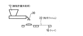
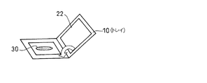
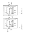
以下、添付図面を用いて、本発明に対する比較例にかかる予備成形樹脂の製造方法について詳細に説明する。図1は、第1の製造工程例を概略的に示した図である。図2は、樹脂計量供給部からフィルムへの樹脂の供給状態を示した図である。図3は、トレイの概略構成図である。図4(A)は打錠プレスの概略構成図、(B)は、冷却プレスの概略構成図である。 Hereinafter, the manufacturing method of the preforming resin concerning the comparative example with respect to this invention is demonstrated in detail using an accompanying drawing. FIG. 1 is a diagram schematically illustrating a first manufacturing process example. FIG. 2 is a diagram showing the state of resin supply from the resin metering unit to the film. FIG. 3 is a schematic configuration diagram of the tray. FIG. 4A is a schematic configuration diagram of a tableting press, and FIG. 4B is a schematic configuration diagram of a cooling press.
製造装置1には、支持体としての複数のトレイ10と、当該トレイ10に対して所定の形状に切断された短冊フィルム22を供給するフィルムカッター20と、粉状または粒状の樹脂を計量し供給可能な樹脂計量供給部12を備えている。また、トレイ10を適宜循環させる循環機構(図示していない)が備わっている。
The manufacturing apparatus 1 measures and supplies a plurality of
なお、比較例におけるトレイ(支持体)10は、図3に示すように、2つの略四角形の枠体がそれぞれ1辺で係着した態様とされている。またこの係着部分を支点に回動可能とされており、当該回動によってトレイの開閉が行なわれる構成とされている。 In addition, as shown in FIG. 3, the tray (support body) 10 in the comparative example is configured such that two substantially quadrangular frames are engaged on one side. Further, the engaging portion can be turned around a fulcrum, and the tray is opened and closed by the turning.
製造装置1では、トレイ(支持体)10が順次循環する態様で用いられ、予備成形樹脂が製造される。図1において示した(1)から(6)の順序に従って、トレイ10が循環しつつ予備成形樹脂の製造が行われる。
In the manufacturing apparatus 1, the tray (support) 10 is used in such a manner that it sequentially circulates, and a preformed resin is manufactured. According to the order of (1) to (6) shown in FIG. 1, the preformed resin is manufactured while the
(1)は、トレイ10の準備工程に相当する位置であり、開かれたトレイ10に対してフィルムカッター20から所定の形状に切断された短冊フィルム22が供給され固定される。このフィルムは例えばPTFE等の材料からなるフィルムが利用される。勿論その他にも、予備成形後の樹脂から容易に剥離することができる限りにおいて種々のフィルムを利用できる。また、トレイ10に対する短冊フィルム22の固定手段も特に限定されるものではない。
(1) is a position corresponding to the preparation step of the
(2)は、樹脂供給の工程に相当する位置であり、製造装置1に備わる樹脂計量供給部12から、粉状樹脂30が所定量計量された上で供給される。この樹脂計量供給部12からの樹脂30の供給は図2のように行なわれる。即ち、トレイ10に短冊フィルム22が固定された状態で且つトレイ10が開いた状態で、樹脂計量供給部12から所定量計量された樹脂30が直接供給されている。
(2) is a position corresponding to the resin supply process, and a predetermined amount of the
(3)は、トレイ10が閉じられる工程に相当する位置であり、当該工程によって粉状樹脂30がトレイ10に固定された短冊フィルム22によって上下から包被される。なお、比較例では、開閉するトレイ10によって粉状樹脂30の包被が行われているが、例えば物理的に分離した別々のトレイ10を上下に重ねて連結固定することで包被を実現するように構成することも可能である。
(3) is a position corresponding to a step in which the
(4)は加熱工程に相当する位置であり、打錠プレス(図1では図示していない)によって短冊フィルム22に包被された粉状樹脂30が所定の形状(例えば、キャビティの形状に相似した形状)に加熱成形される。
(4) is a position corresponding to the heating step, and the
なお、当該加熱工程において用いられる打錠プレス40を図4(A)に示している。この打錠プレス40は当接・離間可能な加熱型42を有しており、この加熱型42が離間したタイミングで当該加熱型42間にトレイ10が侵入し、更に、当該加熱型42が当接することによって短冊フィルム22を介して加熱成形が行なわれる。
In addition, the
(5)は、冷却工程に相当する位置であり、冷却プレス(図1では図示していない)によって加熱工程にて加熱成形された予備成形樹脂30P(ここでは既に加熱成形により所定の形状となっている)の冷却が行なわれる。
(5) is a position corresponding to a cooling process, and is a preformed
なお、当該冷却工程において用いられる冷却プレス50を図4(B)で示している。この冷却プレス50は、所定のタイミングで当接・離間可能な2つの冷却板52を有している。この冷却板52が離間したタイミングで当該冷却板52間にトレイ10が搬送され、更に、冷却板52が当接することによって短冊フィルム22を介して樹脂を冷却する。
In addition, the
(6)は、トレイ10が開かれる工程に相当する位置であり、予備成形樹脂30Pの短冊フィルム22による包被が解かれる。その後、図示せぬ搬送機構によって予備成形樹脂30Pが圧縮成型金型へと搬送され、投入されることとなる。
(6) is a position corresponding to the step in which the
その後は同様の手順を繰り返すことにより、予備成形樹脂30Pが順次製造されることとなる。なお、(1)のトレイ準備工程においては、必要がある場合にのみ短冊フィルム22の供給が行われる。即ち、短冊フィルム22に何らかの損傷(破れや汚れ等)がない限り、繰り返し使用される。
Thereafter, by repeating the same procedure, the preformed
また、比較例においては、少なくとも6個のトレイ10が使用されており、当該6個のトレイ10が、各工程(トレイ準備工程、樹脂供給工程、トレイ閉工程、加熱工程、冷却工程、トレイ開工程)に常に位置して順次循環している。即ち、各工程は他の工程の終了を待たずに自己の工程を進めることが可能となっている。その他にも、例えば、前記6つの工程のうち、1つに空きを設ける(即ち5つのトレイを循環させる)ことで、所謂パズル的にトレイを循環させてもよい。勿論、効率は悪くなるが、4つ以下のトレイを循環させる態様であってもよい。
Further, in the comparative example , at least six
また、比較例では、短冊フィルム22を支持体としてのトレイ10に固定し、当該トレイ10を開閉することで樹脂を上下から包被している。このような方法を採用することによって、フィルムの再利用が可能となり、フィルムに要するコストを低減することができる。また、フィルム22をトレイ10に固定しているためフィルムのハンドリングが容易である。更に、フィルム22がトレイ10に固定された状態で樹脂30を包被しているので、樹脂30を包被するフィルム22に「ズレ」が生じる余地を排除しているため、各工程を循環するに際してフィルム22の同期をとる必要もない。
In the comparative example , the
これに対し、本発明にかかる実施形態においては、例えば、図5に示すような方法を採用することが可能である。 In contrast, in the embodiment according to the present invention, for example, it is possible to employ a method as shown in FIG.
ここでは、樹脂供給工程と、加熱工程とがそれぞれ2段階で行われる構成とされている。その結果、トレイ10の循環が(1)〜(8)の8段階で循環されている。このうち、(2)および(3)が樹脂供給工程、(5)および(6)が加熱工程である。
Here, each of the resin supply process and the heating process is performed in two stages. As a result, the
樹脂供給工程は、(2)として示した第1の樹脂供給工程と、(3)として示した第2の樹脂供給工程とが含まれている。第1の樹脂供給工程においては、第1の樹脂計量供給部12Aによって「最終的に必要な樹脂量」の範囲内でその概量を供給する工程である。一方、第2の樹脂供給工程は、「最終的に必要な樹脂量」と、第1の樹脂供給工程において供給された概量との「差分」を供給する工程である。
The resin supply process includes a first resin supply process shown as (2) and a second resin supply process shown as (3). The first resin supply step is a step of supplying an approximate amount within the range of “finally required resin amount” by the first resin
このように全工程の中で「ボトルネック」となり得る樹脂供給工程を2段階の工程に分割することで、予備成形樹脂のタクトタイムを向上させることが可能となる。即ち、各工程の所要時間を揃えることで、トレイ10の循環をより早いタイミングで行うことができ、所要時間の短い工程に生じうる「待機時間(自己の工程が終了した後トレイ10が巡回するまでの時間)」を削減することができる。更に、第1の樹脂供給工程にて概量を供給しておき、第2の樹脂供給工程で「差分」を(ボトルネックとならない範囲で)時間を掛けて計量供給することができ、予備成形樹脂の成形精度(樹脂量という観点からの成形精度)を向上させることも可能となる。
Thus, by dividing the resin supply process that can be a “bottleneck” in all processes into two stages, it is possible to improve the tact time of the preformed resin. In other words, by aligning the time required for each process, the
また、加熱工程においても第1の加熱工程と、第2の加熱工程とに分割されている。このように全工程の中で「ボトルネック」となり得る加熱工程を複数段階の工程に分割することで、予備成形樹脂のタクトタイムを向上させることが可能となる。即ち、各工程の所要時間を揃えることで、トレイ10の循環をより早いタイミングで行うことができ、所要時間の短い工程に生じうる「待機時間(自己の工程が終了した後トレイ10が巡回するまでの時間)」を削減することができる。更に、単に複数回に分割して加熱成形するのではなく、段階的に異なる「型」を用いて加熱することも可能になる。例えば、図6に示したように、第1の加熱工程では樹脂の中央部にまで熱が伝達可能なように中央部が凸状に盛り上がった「型」42Aを用いて加熱成形し、その後、樹脂全体を万遍なく加熱するように平坦な「型」42Bを用いて再度加熱成形するといったことも可能となっている。即ち、予備成形樹脂の成形精度の向上を図ることが可能となる。
In addition, the heating process is divided into a first heating process and a second heating process. Thus, by dividing the heating process that can be a “bottleneck” in all the processes into a plurality of steps, it is possible to improve the tact time of the preformed resin. In other words, by aligning the time required for each process, the
また上記した実施例においては、トレイ10を平面的に循環しながら各工程を行なっているが、図7に示すように垂直方向の循環を取り入れてトレイを循環させることも可能である。例えば図7に示すようにトレイ10の循環工程の一部にエレベーター機構を用いてトレイ10を垂直方向に循環可能に構成すれば、製造装置の据付面積(フットプリント)を小さく構成することが可能となる。
In the above-described embodiment, each process is performed while circulating the
また、図8に示すように、複数のトレイ10をキャタピラ状(無限軌道体体状)に連結し順次この連結したトレイ10を回転移動させることによって予備成形樹脂を製造することも可能である。
In addition, as shown in FIG. 8, it is also possible to manufacture a preformed resin by connecting a plurality of
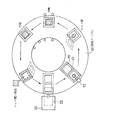
また、図9に示したように、複数のトレイ10を1枚の回転テーブル60上に適宜配置し、当該回転テーブル60を回転させることによってそれぞれの位置にて各工程の作業を行ない予備成形樹脂を製造することも可能である。
Further, as shown in FIG. 9, a plurality of
なお、上記説明では、各工程がそれぞれ別の位置(次段)にて行われているが、部分的に同じ位置にて行われる工程が存在してもよい。即ち、他の工程に過度の「待機時間」を生じさせない限りにおいて、例えば、同じ位置にて「樹脂供給」と「トレイ閉じ」を行うような構成を排除するものではない。 In the above description, each process is performed at a different position (next stage), but there may be a process performed partially at the same position. That is, as long as excessive “standby time” is not generated in other processes, for example, a configuration in which “resin supply” and “tray closing” are performed at the same position is not excluded.
また、上記実施形態では支持体として開閉可能は枠状のトレイ10を例示して説明しているが、このような構成に限定される趣旨のものではない。短冊フィルムを支持することができる(例えば皺が生じない程度に支持することができる)限りにおいて、種々の構成を採用することが可能である。
In the above embodiment, the frame-
半導体チップを搭載した被成形品を樹脂にて圧縮封止する圧縮型の樹脂封止装置(樹脂封止金型)に対して予備成形樹脂を効率よく供給できる。 The preformed resin can be efficiently supplied to a compression type resin sealing device (resin sealing mold) that compresses and seals a molded product on which a semiconductor chip is mounted with resin.
1…製造装置(予備成形樹脂製造装置)
10…トレイ
12…樹脂計量供給部
20…フィルムカッター
22…短冊フィルム
30…粉状樹脂
30P…予備成形樹脂
40…打錠プレス(加熱プレス)
50…冷却プレス
1 ... Production equipment (Preliminary resin production equipment)
DESCRIPTION OF
50 ... Cooling press
Claims (6)
前記粉状または粒状の樹脂を包被するために所定の形状に切断されたフィルムを支持体に固定するフィルム固定工程と、
前記支持体に固定された前記フィルム上に前記粉状または粒状の樹脂を供給する樹脂供給工程と、
前記フィルム上に供給された前記粉状または粒状の樹脂を包被する包被工程と、
前記包被された状態のままで前記フィルムを介して前記粉状または粒状の樹脂を複数段階に分割された加熱工程を行うことにより所定の形状に予備成形する予備成形工程と、を含む
ことを特徴とする予備成形樹脂の製造方法。 Prior to charging into a compression mold, a method for producing a preformed resin that preforms a powdery or granular resin into a predetermined shape,
A film fixing step of fixing a film cut into a predetermined shape to encapsulate the powdery or granular resin on a support;
A resin supplying step of supplying the powdery or granular resin on the film fixed to the support;
An enveloping step of encapsulating the powdery or granular resin supplied on the film;
A preforming step in which the powdered or granular resin is preformed into a predetermined shape by performing a heating process divided into a plurality of stages through the film in the encapsulated state. A method for producing a preformed resin.
前記予備成形工程が、更に、
前記加熱により所定の形状に成形された前記樹脂を冷却する冷却工程と、を含み、
かつ、
前記支持体が複数用意されることにより、前記フィルム固定工程、樹脂供給工程、包被工程、加熱工程、冷却工程のうち少なくとも2つ以上の工程が同時に進行している
ことを特徴とする予備成形樹脂の製造方法。 In claim 1,
The preforming step further comprises:
Cooling the resin molded into a predetermined shape by the heating, and
And,
By preparing a plurality of the supports, at least two or more steps among the film fixing step, the resin supplying step, the covering step, the heating step, and the cooling step are simultaneously performed. Manufacturing method of resin.
前記樹脂供給工程が、
最終的な必要量の範囲内で概量を供給する第1の樹脂供給工程と、
前記必要量と前記概量との差分を供給する第2の樹脂供給工程と、を含む
ことを特徴とする予備成形樹脂の製造方法。 In claim 1 or 2,
The resin supply step includes
A first resin supply step of supplying an approximate amount within the final required amount;
A second resin supply step for supplying a difference between the required amount and the approximate amount. A method for producing a preformed resin.
前記複数段階に分割された加熱工程が、
前記粉状または粒状の樹脂を第1の形状に加熱成形する第1の加熱工程と、
前記第1の形状とされた前記樹脂を第2の形状に加熱成形する第2の加熱工程と、を含む
ことを特徴とする予備成形樹脂の製造方法。 In any one of claims 1 to 3,
The heating process divided into the plurality of stages ,
A first heating step of thermoforming the powdery or granular resin into a first shape;
And a second heating step of heat-molding the resin having the first shape into a second shape. A method for manufacturing a preformed resin.
前記支持体が少なくとも工程の数だけ用意されることにより、全ての工程が同時に進行している
ことを特徴とする予備成形樹脂の製造方法。 In any of claims 2 to 4,
By preparing at least the number of steps of the support, all the steps are proceeding simultaneously. A method for producing a preformed resin.
所定の形状に切断されたフィルムと、
該フィルムを固定可能な支持体と、を備え、
該支持体に固定されたフィルムによって前記粉状または粒状の樹脂を包被した上で複数段階に分割された加熱を行うことにより予備成形する
ことを特徴とする予備成形樹脂の製造装置。 Prior to charging into a compression mold, a preformed resin manufacturing apparatus that preforms a powdery or granular resin into a predetermined shape,
A film cut into a predetermined shape;
A support capable of fixing the film,
An apparatus for producing a preformed resin, wherein the powdery or granular resin is encapsulated by a film fixed to the support, and preformed by performing heating divided into a plurality of stages .
Priority Applications (1)
| Application Number | Priority Date | Filing Date | Title |
|---|---|---|---|
| JP2007200697A JP5111970B2 (en) | 2007-08-01 | 2007-08-01 | Method and apparatus for producing preformed resin |
Applications Claiming Priority (1)
| Application Number | Priority Date | Filing Date | Title |
|---|---|---|---|
| JP2007200697A JP5111970B2 (en) | 2007-08-01 | 2007-08-01 | Method and apparatus for producing preformed resin |
Publications (2)
| Publication Number | Publication Date |
|---|---|
| JP2009034887A JP2009034887A (en) | 2009-02-19 |
| JP5111970B2 true JP5111970B2 (en) | 2013-01-09 |
Family
ID=40437264
Family Applications (1)
| Application Number | Title | Priority Date | Filing Date |
|---|---|---|---|
| JP2007200697A Active JP5111970B2 (en) | 2007-08-01 | 2007-08-01 | Method and apparatus for producing preformed resin |
Country Status (1)
| Country | Link |
|---|---|
| JP (1) | JP5111970B2 (en) |
Families Citing this family (3)
| Publication number | Priority date | Publication date | Assignee | Title |
|---|---|---|---|---|
| JP5336974B2 (en) * | 2009-08-06 | 2013-11-06 | 住友重機械工業株式会社 | Resin sealing device and resin sealing method |
| JP5248453B2 (en) * | 2009-09-18 | 2013-07-31 | 住友重機械工業株式会社 | Resin sealing device and resin sealing method |
| JP2011224911A (en) * | 2010-04-21 | 2011-11-10 | Sumitomo Heavy Ind Ltd | Compression-molding device and compression-molding method |
Family Cites Families (11)
| Publication number | Priority date | Publication date | Assignee | Title |
|---|---|---|---|---|
| JPS576714A (en) * | 1980-06-14 | 1982-01-13 | Matsushita Electric Works Ltd | Apparatus for producing tablet of thermoplastic resin molding material |
| JPH09290419A (en) * | 1996-04-25 | 1997-11-11 | Toshiba Chem Corp | Manufacture of resin molded body |
| JP3944328B2 (en) * | 1999-03-19 | 2007-07-11 | 日本ゼオン株式会社 | Manufacturing method of press-molded body |
| CN101045852B (en) * | 2001-10-30 | 2011-02-09 | 日立化成工业株式会社 | Sealing material tablet, method of manufacturing the tablet and electronic component device |
| JP3986052B2 (en) * | 2001-12-04 | 2007-10-03 | 住友重機械工業株式会社 | Resin sealing apparatus and method |
| JP3914129B2 (en) * | 2002-10-11 | 2007-05-16 | 住友重機械工業株式会社 | Semi-cured flat resin molding apparatus and molding method thereof |
| JP4253266B2 (en) * | 2004-03-16 | 2009-04-08 | 住友重機械工業株式会社 | Flat resin molding equipment |
| JP4253269B2 (en) * | 2004-03-31 | 2009-04-08 | 住友重機械工業株式会社 | Molding resin and sheet peeling structure and flat resin and sheet peeling method |
| JP4431440B2 (en) * | 2004-05-25 | 2010-03-17 | 住友重機械工業株式会社 | Resin supply device and resin supply method |
| JP4622388B2 (en) * | 2004-08-26 | 2011-02-02 | 東洋製罐株式会社 | Compression molding system |
| JP4791851B2 (en) * | 2006-02-24 | 2011-10-12 | Towa株式会社 | Resin sealing molding equipment for electronic parts |
-
2007
- 2007-08-01 JP JP2007200697A patent/JP5111970B2/en active Active
Also Published As
| Publication number | Publication date |
|---|---|
| JP2009034887A (en) | 2009-02-19 |
Similar Documents
| Publication | Publication Date | Title |
|---|---|---|
| CN103660138B (en) | The manufacture method of polychrome formed products and injection molding system | |
| JP5745595B2 (en) | Vacuum insulation core material production system (SYSTEMFORMANUMACTURINGCOREOFVACUUMINSULATIONPANEL) | |
| EP0907481B1 (en) | Injection molding apparatus and method | |
| TWI606526B (en) | Resin molding device and resin molding method | |
| CN102171013B (en) | Compression molding method and device | |
| KR102266607B1 (en) | Resin molding apparatus and method for manufacturing resin molded article | |
| JP7203414B2 (en) | Resin supply/take-out device, workpiece transfer device, and resin molding device | |
| JP2014231185A (en) | Resin molding apparatus and resin molding method | |
| CN105479674A (en) | Molding tool and method for the production of an optical element | |
| JP5111970B2 (en) | Method and apparatus for producing preformed resin | |
| CN106252056A (en) | A kind of integrated inductor manufacturing method | |
| JPH0639939A (en) | Method for molding and assembling micro parts | |
| TWI854661B (en) | Mold die, resin molding apparatus, and method for producing resin molded product | |
| CN101903152A (en) | Casting machine system and method for manufacturing metal/plastic-hybrid parts | |
| JP2021031302A (en) | Smart automatic mold exchange system and smart automatic mold exchange method | |
| TWI599467B (en) | Molding unit, compression molding apparatus and compression molding method | |
| KR102853881B1 (en) | Molding method of vacuum forming system | |
| CN117382063B (en) | Energy-saving hot-press forming equipment for producing melamine tableware and use method thereof | |
| JPH09186183A (en) | Semiconductor encapsulation mold device, semiconductor encapsulation device using the mold device, and encapsulation resin molding method for semiconductor device | |
| JPH09267387A (en) | Manufacture of carrier tape | |
| JPH05138683A (en) | Rotary injection molding machine | |
| JP3226879U (en) | Smart automatic mold change system | |
| JP2007131466A (en) | Optical lens manufacturing method and optical lens manufacturing apparatus | |
| KR20230059535A (en) | System and method for manufacturing composite material | |
| CN104886793A (en) | Bra cup production device |
Legal Events
| Date | Code | Title | Description |
|---|---|---|---|
| A621 | Written request for application examination |
Free format text: JAPANESE INTERMEDIATE CODE: A621 Effective date: 20091013 |
|
| A977 | Report on retrieval |
Free format text: JAPANESE INTERMEDIATE CODE: A971007 Effective date: 20120116 |
|
| A131 | Notification of reasons for refusal |
Free format text: JAPANESE INTERMEDIATE CODE: A131 Effective date: 20120131 |
|
| A521 | Request for written amendment filed |
Free format text: JAPANESE INTERMEDIATE CODE: A523 Effective date: 20120402 |
|
| TRDD | Decision of grant or rejection written | ||
| A01 | Written decision to grant a patent or to grant a registration (utility model) |
Free format text: JAPANESE INTERMEDIATE CODE: A01 Effective date: 20121002 |
|
| A01 | Written decision to grant a patent or to grant a registration (utility model) |
Free format text: JAPANESE INTERMEDIATE CODE: A01 |
|
| A61 | First payment of annual fees (during grant procedure) |
Free format text: JAPANESE INTERMEDIATE CODE: A61 Effective date: 20121010 |
|
| FPAY | Renewal fee payment (event date is renewal date of database) |
Free format text: PAYMENT UNTIL: 20151019 Year of fee payment: 3 |
|
| R150 | Certificate of patent or registration of utility model |
Ref document number: 5111970 Country of ref document: JP Free format text: JAPANESE INTERMEDIATE CODE: R150 Free format text: JAPANESE INTERMEDIATE CODE: R150 |
|
| S111 | Request for change of ownership or part of ownership |
Free format text: JAPANESE INTERMEDIATE CODE: R313113 |
|
| R350 | Written notification of registration of transfer |
Free format text: JAPANESE INTERMEDIATE CODE: R350 |
|
| R250 | Receipt of annual fees |
Free format text: JAPANESE INTERMEDIATE CODE: R250 |
|
| R250 | Receipt of annual fees |
Free format text: JAPANESE INTERMEDIATE CODE: R250 |
|
| R250 | Receipt of annual fees |
Free format text: JAPANESE INTERMEDIATE CODE: R250 |
|
| R250 | Receipt of annual fees |
Free format text: JAPANESE INTERMEDIATE CODE: R250 |
|
| R250 | Receipt of annual fees |
Free format text: JAPANESE INTERMEDIATE CODE: R250 |
|
| R250 | Receipt of annual fees |
Free format text: JAPANESE INTERMEDIATE CODE: R250 |
|
| R250 | Receipt of annual fees |
Free format text: JAPANESE INTERMEDIATE CODE: R250 |
|
| R250 | Receipt of annual fees |
Free format text: JAPANESE INTERMEDIATE CODE: R250 |