JP5103404B2 - Drawer guide system for bag - Google Patents
Drawer guide system for bag Download PDFInfo
- Publication number
- JP5103404B2 JP5103404B2 JP2008543608A JP2008543608A JP5103404B2 JP 5103404 B2 JP5103404 B2 JP 5103404B2 JP 2008543608 A JP2008543608 A JP 2008543608A JP 2008543608 A JP2008543608 A JP 2008543608A JP 5103404 B2 JP5103404 B2 JP 5103404B2
- Authority
- JP
- Japan
- Prior art keywords
- drawer
- rotating member
- guide system
- rail
- drawer guide
- Prior art date
- Legal status (The legal status is an assumption and is not a legal conclusion. Google has not performed a legal analysis and makes no representation as to the accuracy of the status listed.)
- Active
Links
Images


Classifications
-
- A—HUMAN NECESSITIES
- A47—FURNITURE; DOMESTIC ARTICLES OR APPLIANCES; COFFEE MILLS; SPICE MILLS; SUCTION CLEANERS IN GENERAL
- A47B—TABLES; DESKS; OFFICE FURNITURE; CABINETS; DRAWERS; GENERAL DETAILS OF FURNITURE
- A47B88/00—Drawers for tables, cabinets or like furniture; Guides for drawers
- A47B88/40—Sliding drawers; Slides or guides therefor
- A47B88/483—Sliding drawers; Slides or guides therefor with single extensible guides or parts
- A47B88/487—Sliding drawers; Slides or guides therefor with single extensible guides or parts with rollers, ball bearings, wheels, or the like
-
- A—HUMAN NECESSITIES
- A47—FURNITURE; DOMESTIC ARTICLES OR APPLIANCES; COFFEE MILLS; SPICE MILLS; SUCTION CLEANERS IN GENERAL
- A47B—TABLES; DESKS; OFFICE FURNITURE; CABINETS; DRAWERS; GENERAL DETAILS OF FURNITURE
- A47B88/00—Drawers for tables, cabinets or like furniture; Guides for drawers
- A47B88/40—Sliding drawers; Slides or guides therefor
- A47B88/437—Rollers for slides or guides
-
- A—HUMAN NECESSITIES
- A47—FURNITURE; DOMESTIC ARTICLES OR APPLIANCES; COFFEE MILLS; SPICE MILLS; SUCTION CLEANERS IN GENERAL
- A47B—TABLES; DESKS; OFFICE FURNITURE; CABINETS; DRAWERS; GENERAL DETAILS OF FURNITURE
- A47B88/00—Drawers for tables, cabinets or like furniture; Guides for drawers
- A47B88/40—Sliding drawers; Slides or guides therefor
- A47B88/49—Sliding drawers; Slides or guides therefor with double extensible guides or parts
- A47B88/493—Sliding drawers; Slides or guides therefor with double extensible guides or parts with rollers, ball bearings, wheels, or the like
Description
本発明は、カーカスレール、引出レール及びオプションでカーカスレールと引出レール
との間に設置される中間レールを有した箪笥用の引出ガイドシステムに関する。
The present invention relates to a drawer guide system for a bag having a carcass rail, a drawer rail, and optionally an intermediate rail installed between the carcass rail and the drawer rail.
引出部に作用する荷重は、第1回転部材と、少なくとも1体が存在する第2回転部材と
によって受けられつつ運搬される。
The load acting on the drawer is transported while being received by the first rotating member and the second rotating member having at least one body.
この形態の引出ガイドは、通常は家具本体の両側板上にアレンジされており、重荷重を
支持しつつ引出部あるいは棚底部を円滑に走行させる。円滑走行に加えて、引出部の傾斜
を防止するためには、引出部又は引出ガイドの個々の部材の横方向の安定性も重要である
。
The drawer guides in this form are usually arranged on both side plates of the furniture body, and smoothly run through the drawer part or the shelf bottom part while supporting a heavy load. In addition to smooth running, the lateral stability of the individual members of the drawer or drawer guide is also important in order to prevent the drawer from tilting.
特に重荷重が作用している場合に、引出部が閉位置にあるときには、先頭の回転部材又
はキャスタあるいはレール間にアレンジされた運搬部の先頭域には相当なる圧力が作用す
る。もしプラスチック製のローラが回転部材として利用されると、引出ガイドの走行時に
ローラが変形し、走行に悪影響を及ぼす可能性がある。
In particular, when a heavy load is applied, when the drawer is in the closed position, a considerable pressure is applied to the leading region of the transporting part arranged between the leading rotating member or caster or rail. If a plastic roller is used as the rotating member, the roller may be deformed when the drawer guide is traveling, which may adversely affect traveling.
従って本発明の1目的は、改善された走行特性を備えた前述の引出ガイドシステムの提
供である。
Accordingly, one object of the present invention is to provide the aforementioned withdrawal guide system with improved running characteristics.
この目的は、本発明の1好適実施例によって達成される。この実施例では、第1回転部
材は、(少なくとも1つの回転部材から構成されている)第2回転部材よりも小さい直径を有しており、引出レールは、引出部が閉じられるとき第1回転部材には引出レールによって荷重が作用するが、引出部が開けられるときには、第1回転部材が引出レールの荷重が解放されるように設計されている。
This object is achieved by one preferred embodiment of the present invention. In this embodiment, the first rotating member (that is composed of at least one rotary member) has a smaller diameter than the second rotary member, the pull-out rail, the first rotating when the drawer unit is closed A load is applied to the member by the pull-out rail, but when the pull-out portion is opened, the first rotating member is designed to release the load of the pull-out rail.
このように閉位置において引出部に作用する荷重は、運搬部の先頭の回転部材又は先頭
のキャスタに移動され、引出部が閉じられているときには、残りの回転部材からは荷重が
解放されるため、それらには荷重はほとんど、あるいは全く作用しない。引出部が閉じら
れるときに荷重が作用するレール縦方向に移動できる第1回転部材には機械的圧力が作用
するが、第1回転部材の漸進的な平坦化変形は現実には許容される。なぜなら、その小径
と引出レールの特殊デザインのために引出部が閉じているときには回転部材は、好適には
引出部の支持作用のみを提供するからである。
Thus, the load acting on the drawer portion in the closed position is moved to the leading rotating member or the leading caster of the transporting portion, and when the leading portion is closed, the load is released from the remaining rotating members. They have little or no load. A mechanical pressure is applied to the first rotating member that can move in the longitudinal direction of the rail to which a load is applied when the drawer is closed, but a gradual flattening deformation of the first rotating member is actually allowed. This is because the rotating member preferably only provides support for the drawer when the drawer is closed due to its small diameter and the special design of the drawer rail.
しかし、好適には、引出部が開位置にあるとき回転部材はキャスタとしては働かない。 Preferably, however, the rotating member does not act as a caster when the drawer is in the open position.
円滑な走行を確実にするため、引出部が開けられるときには引出レールを、好適には第
2回転部材上のみで走行させることができる。
In order to ensure smooth running, the drawer rail can be run only on the second rotating member when the drawer portion is opened.
本発明の1実施例によれば、第1回転部材の直径は、第2回転部材の直径の98%以下
、好適には97%以下である。第1回転部材の直径を第2回転部材の直径よりも0.1m
m、好適には0.2mmだけ小さくすることもできる。
According to one embodiment of the present invention, the diameter of the first rotating member is 98% or less, preferably 97% or less of the diameter of the second rotating member. The diameter of the first rotating member is 0.1 m larger than the diameter of the second rotating member.
m, preferably 0.2 mm.
本発明の1好適実施例によれば、走行面の前端域において、引出レールは、回転部材側
に突出する凸部を有する。引出部の閉位置において引出レールは、その凸部を第1回転部
材に圧接させる。その結果、第1回転部材には、ほぼ垂直方向に荷重が作用する。形成さ
れた凸部は、好適には第1回転部材に対してのみ作用し、残余の回転部材には、荷重レー
ルの凸部による荷重は作用しない。
According to one preferred embodiment of the present invention, at the front end region of the running surface, drawer rail has a convex portion out collision to the rotating member side. In the closed position of the drawer portion, the drawer rail presses the convex portion against the first rotating member. As a result, a load acts on the first rotating member in a substantially vertical direction. The formed convex portion preferably acts only on the first rotating member, and the load due to the convex portion of the load rail does not act on the remaining rotating member.
構造的に単純な設計にするには、凸部は、1材料で、好適には1膨出域として引出レー
ル上に形成される。押型を利用して引出レールを形状加工することでこの凸部を工場にお
いて簡単に引出レールに成型することもできる。あるいは凸部は、別部材で準備され、引
出レールに取り付けられる。このような別部材をプラスチックプレートとし、引出レール
の回転部材側のレール走行面に接着することもできる。
For a structurally simple design, the protrusions are formed on the drawer rail with one material, preferably as one bulge area. By projecting the shape of the pull-out rail using a pressing die, the convex portion can be easily formed into the pull-out rail at the factory. Or a convex part is prepared with another member, and is attached to a drawer rail. Such another member can be a plastic plate and can be adhered to the rail running surface of the drawer rail on the rotating member side.
引出部が閉じられると、引出レールの凸部は、好適には第1回転部材のみに圧接される
。閉位置では、第1(先頭)回転部材には荷重が作用し、追加の回転部材は引出部の閉位
置ではほぼ無荷重状態となる。
When the drawer portion is closed, the convex portion of the drawer rail is preferably in pressure contact with only the first rotating member. In the closed position, a load is applied to the first (leading) rotating member, and the additional rotating member is almost unloaded in the closed position of the drawer portion.
本発明の1好適実施例では、凸部は回転部材のために、少なくとも1つの傾斜部を有し
ている。この傾斜部によって、第1回転部材は、凸部の角段部を乗り越える必要がないた
め引出部の閉作動時の非円滑動作は防止される。
In one preferred embodiment of the invention, the projection has at least one ramp for the rotating member. By this inclined portion, the first rotating member does not need to get over the angular step portion of the convex portion, and therefore, non-smooth operation during the closing operation of the drawer portion is prevented.
本発明の1好適実施例では、第1回転部材及び(少なくとも1つの回転部材から構成されている)第2回転部材は、引出部の移動方向にて前後に配置される。好適なデザインでは、第1回転部材と第2回転部材は、移動式運搬部内に配置されている。 In one preferred embodiment of the present invention, the first rotary member and (that consists of at least one rotary member) second rotary member is disposed in front-rear direction of movement of the drawer unit. In a preferred design, the first rotating member and the second rotating member are disposed in the mobile transporter.
本発明の1好適実施例では、第1回転部材の表面には、プラスチック製のカバーが形成
されている。このプラスチック材料は、弾性変形特性を有することができる。しかし、金
属回転部材でも好適に利用できる。
In a preferred embodiment of the present invention, a plastic cover is formed on the surface of the first rotating member. The plastic material can have elastic deformation characteristics. However, a metal rotating member can be suitably used.
本明細書で使用する用語「回転部材」とは、本発明の趣旨に沿ってレール間にて移動で
きる回転部材に加えて、キャスタ、筒型ローラ、ディスク体、ボール体等の概念を含む。
これら異種の回転部材を組み合わせて利用することも可能である。
The term “rotating member” used in the present specification includes concepts such as a caster, a cylindrical roller, a disk body, and a ball body in addition to a rotating member that can move between rails in accordance with the spirit of the present invention.
It is also possible to use these different types of rotating members in combination.
本発明のさらなる詳細と利点は、添付図面を利用した以下の詳細な説明において解説さ
れている。
Further details and advantages of the present invention are set forth in the following detailed description using the accompanying drawings.
図1aと図1bは、従来技術の引出ガイドシステム1の概略側面図である。
FIGS. 1 a and 1 b are schematic side views of a prior art
回転部材5a、5b及び5cを保有した運搬部9が、カーカスレール2と、引出レール
3との間で移動できるようにアレンジされている。
The
運搬部9は、重荷重が作用しているときにカーカスレール2に対する引出レール3の自
由走行を提供する。
The
引出部は、相当期間、閉位置に存在すると、引出部の前面部が重いときには特に相当な
荷重が作用するため、先頭の回転部材5aは、徐々に変形する。
If the drawer portion is in the closed position for a considerable period of time, a considerable load is applied particularly when the front portion of the drawer portion is heavy, so that the leading rotating
回転部材5aは、時間が経つにつれて脱円形となり、引出ガイドシステム1の走行性能に悪影響を及ぼす。
The rotating
図1bでは、回転部材5aの非円形である楕円形状が概略的に図示されている。この場
合、たとえ回転部材5aの僅かな変形であっても円滑な走行に悪影響する。
In FIG. 1b, the non-circular elliptical shape of the rotating
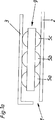
図2aと図2bは、本発明に従った引出ガイドシステム1を図示している。引出部に作
用する荷重は、カーカスレール2と引出レール3との間で移動できるようにアレンジされ
た運搬部9によって受けられつつ運搬される。図1aと図1bで示す従来技術とは異なり、運搬部9は、2体の第2回転部材5a、5bよりも小さい直径を有する第1回転部材4を含んでいる。さらに、第1及び第2回転部材4、5a、5b側に突出する凸部7が引出レール3の前端域に取り付け又はアレンジされている。この結果、引出部が閉じられると引出レール3によって、第1回転部材4に荷重が作用し、引出部を開けるときには引出レール3は、第1回転部材を荷重から解放させる。換言すれば引出部は、引出部が閉じると、引出レール3によって第1回転部材4のみに荷重が作用し、引出部が閉じられているときには、他の2体の第2回転部材5aと5bは実質的に無荷重状態であり、従って変形しない。
Figures 2a and 2b illustrate a
引出部が閉じられているときには、第1回転部材4は、このように好適には支持ローラ
として作用するが、引出部が開けられるときには、引出レール3は、好適には2体の第2
回転部材5aと5b上のみを走行する。第1回転部材4が全体的又は部分的にプラスチッ
ク製である場合、図2bに図示するように時間が経つにつれて変形する可能性がある。し
かしながら、直径が小さいため、第1回転部材4は、実際のキャスタとして働かず、非円
形形状であっても問題はない。
When the drawer portion is closed, the first rotating
It runs only on the rotating
開位置では、引出レール3は、2つの第2回転部材5aと5b上のみを走行する。凸部
7は、好適には引出レール3上の1部材で1膨出域として形成されているが、別部材とし
て引出レール3へ取り付けることもできる。凸部7は、少なくとも第1回転部材4のため
に少なくとも1つの傾斜部8を有している。図面では、傾斜部8は、第2回転部材5aの
ための停止部としても作用する。
In the open position, the
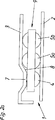
図3は、家具の1側壁上に両側が取り付けられたカーカスレール2を有する引出ガイドシステム1を図示している。
FIG. 3 illustrates a
引出レール3は、カーカスレール2に対して移動できる。引出部が閉じているときには
、1膨出域として形成された引出レール3の凸部7の下に小型の第1回転部材4が位置する。説明を簡単にするため、引出レール3の傾斜調整部、引出ベース等のための付属品等、本発明にとって必要ではない引出ガイドシステム1のさらなる詳細は図示しない。
The
図4aから図4cは、引出ガイドシステム1をそれぞれ図示している。
FIGS. 4 a to 4 c illustrate the
図4aは、引出ガイドシステム1の平面図、図4bは、運搬部9の断面を示す側面図である。運搬部9は、他の2体の回転部材5aと5bの直径よりも小さい直径を有する第1回転部材4を含んでいる。
FIG. 4 a is a plan view of the
図4bは、引出ガイドシステム1の閉状態を図示しており、引出レール3は、第1回転部材4側に突出する凸部7を第1回転部材4に圧接させた状態で図示されている。
Figure 4b is shown the closed state of the
図4cは、図4bの円部の詳細図であり、第1回転部材4には引出レール3の凸部7に
よる荷重が作用している。
FIG. 4 c is a detailed view of the circular portion of FIG. 4 b, and a load due to the
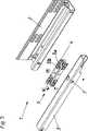
図5は、カーカスレール2と、引出レール3と、これら2本のレール2と3との間を移
動できる運搬部9とを有する引出ガイドシステム1の分解図である。運搬部9の先頭の第1回転部材4は、他の2体の回転部材5aと5bよりも少々小さく、引出部が閉められるときは引出レール3の凸部7と係合する。運搬部9は、また、開閉移動中に引出ガイドシステム1に好ましい安定性を提供する追加の水平並びに垂直ローラを有している。
FIG. 5 is an exploded view of the
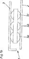
図6aは、引出レール3の凸部7が第1回転部材4(図示せず)に圧接し、残りの回転
部材5aと5bは、引出レール3から解放された状態の、閉位置に存在する引出ガイドシステム1を図示している。これらの部品は、閉じられた引出部の荷重の作用によって変形しない。
In FIG. 6 a, the
図6bは、開位置に存在する引出ガイドシステム1を図示しており、第1回転部材4は、引出レール3の重量から解放され、引出レール3は、第2回転部材5aと5b上のみを走行する。
FIG. 6b illustrates the
本発明は、図示した実施例に限定されず、添付の請求の範囲内である本発明の変形や技
術的均等物を含んでいる。明細書中の説明で使用した上、下、横等の位置関係は、引出ガ
イドの慣例的な設置ポジション、あるいは図面でのポジションを示したものであり適宜変
更することができる。
The present invention is not limited to the illustrated embodiments, but includes modifications and technical equivalents of the present invention which are within the scope of the appended claims. The positional relationship such as upper, lower, and horizontal used in the description of the specification indicates a conventional installation position of the drawer guide or a position in the drawing, and can be changed as appropriate.
Claims (18)
引出部に作用する荷重は、第1回転部材(4)と、少なくとも1つの回転部材から構成されている第2回転部材(5a)とによって受けられつつ運搬され、
前記第1回転部材(4)は、前記第2回転部材(5a)よりも小さい直径を有しており、
前記引出レール(3)は、前記引出部が閉じられるとき前記第1回転部材(4)には、
前記引出レール(3)によって荷重が作用するが、前記引出部が開けられるときには、 前記第1回転部材が前記引出レール(3)の荷重から解放されるように、前記第1回転部材(4)側に突出する凸部(7)を有することを特徴とする引出ガイドシステム(1)。 A carcass rail (2), a drawer guide system comprising a lead rail (3),
Load acting on the lead-out portion includes a first rotating member (4), is transported while received by the second rotating member that is composed of at least one rotary member (5a),
The first rotating member (4) has a smaller diameter than the previous SL second rotating member (5a),
The drawer rail (3) has the first rotating member (4) when the drawer portion is closed.
Although the load is applied by the drawer rail (3), when the drawer portion is opened , the first rotary member (4) is released so that the first rotary member is released from the load of the drawer rail (3 ). drawer guide system characterized Rukoto that Yusuke protrusion protruding on the side (7) (1).
ム。When the lead portion is closed convex end of the lead rail (3) (7), pull-out guide system according to any one of claims 1 to 7, characterized in that it is pressed against only the first rotating member (4) .
求項1から11のいずれかに記載の引出ガイドシステム。12. A drawer guide system according to any one of the preceding claims, characterized in that the first rotating member (4) is wholly or partly made of plastic.
とする請求項12記載の引出ガイドシステム。The drawer guide system according to claim 12, characterized in that a plastic cover is formed on the surface of the first rotating member (4).
求項1から13のいずれかに記載の引出ガイドシステム。14. The drawer guide system according to claim 1, wherein at least the first rotating member (4) is formed as a caster.
請求項1から13のいずれかに記載の引出ガイドシステム。14. The drawer guide system according to claim 1, wherein at least the first rotating member (4) is formed as a cylindrical roller.
請求項1から13のいずれかに記載の引出ガイドシステム。14. A drawer guide system according to claim 1, wherein at least the first rotating member (4) is formed as a disc body.
求項1から13のいずれかに記載の引出ガイドシステム。14. The drawer guide system according to claim 1, wherein at least the first rotating member (4) is formed as a ball body.
を特徴とする請求項1から17のいずれかに記載の引出ガイドシステム。The drawer guide system according to any one of claims 1 to 17.
Applications Claiming Priority (3)
| Application Number | Priority Date | Filing Date | Title |
|---|---|---|---|
| ATGM824/2005 | 2005-12-06 | ||
| AT0082405U AT8732U1 (en) | 2005-12-06 | 2005-12-06 | EXTRACTION SYSTEM FOR DRAWERS |
| PCT/AT2006/000430 WO2007065180A1 (en) | 2005-12-06 | 2006-10-23 | Pull-out guide system for drawers |
Publications (2)
| Publication Number | Publication Date |
|---|---|
| JP2009518078A JP2009518078A (en) | 2009-05-07 |
| JP5103404B2 true JP5103404B2 (en) | 2012-12-19 |
Family
ID=37056683
Family Applications (1)
| Application Number | Title | Priority Date | Filing Date |
|---|---|---|---|
| JP2008543608A Active JP5103404B2 (en) | 2005-12-06 | 2006-10-23 | Drawer guide system for bag |
Country Status (8)
| Country | Link |
|---|---|
| US (1) | US7690740B2 (en) |
| EP (1) | EP1959794B2 (en) |
| JP (1) | JP5103404B2 (en) |
| CN (1) | CN101299945B (en) |
| AT (2) | AT8732U1 (en) |
| ES (1) | ES2385742T5 (en) |
| MY (1) | MY150917A (en) |
| WO (1) | WO2007065180A1 (en) |
Families Citing this family (20)
| Publication number | Priority date | Publication date | Assignee | Title |
|---|---|---|---|---|
| DE202008017061U1 (en) * | 2008-12-23 | 2009-04-09 | Grass Gmbh | Device with a guide unit for guiding a relative to a body movable furniture drawer and furniture |
| AT508988B1 (en) * | 2009-12-03 | 2011-07-15 | Blum Gmbh Julius | drawer |
| WO2011146951A1 (en) | 2010-05-25 | 2011-12-01 | Julius Blum Gmbh | Rolling body of a moving carriage cage for drawer guides |
| DE102010042180A1 (en) * | 2010-10-08 | 2012-04-12 | Schock Metallwerk Gmbh | pull-out guide |
| US8851587B2 (en) * | 2011-07-05 | 2014-10-07 | Jonathan Manufacturing Corporation | Heavy-duty slide assembly |
| EP2863774B1 (en) * | 2012-06-25 | 2017-02-22 | Paul Hettich GmbH & Co. KG | Pull-out guide device for furniture parts that are movable relative to one another comprising a roller bearing device |
| DE102012106751A1 (en) * | 2012-07-25 | 2014-01-30 | Paul Hettich Gmbh & Co. Kg | Pull-out guide for relatively movable furniture parts |
| AT514810B1 (en) * | 2013-09-23 | 2015-04-15 | Blum Gmbh Julius | Floating support roller |
| AT515039B1 (en) * | 2013-11-04 | 2017-10-15 | Blum Gmbh Julius | drawer |
| AT515367B1 (en) * | 2014-01-23 | 2017-11-15 | Blum Gmbh Julius | drawer |
| DE102014108854A1 (en) | 2014-06-25 | 2015-12-31 | Paul Hettich Gmbh & Co. Kg | Pull-out guide for relatively movable furniture parts |
| DE202014103864U1 (en) * | 2014-08-20 | 2015-11-23 | Grass America, Inc. | Pull-out guide for guiding a drawer and furniture with a pull-out guide |
| EP2992782B1 (en) | 2014-09-03 | 2019-05-08 | Apparatebau Gronbach Srl | Slide assembly |
| KR102337161B1 (en) * | 2014-11-26 | 2021-12-08 | 삼성전자주식회사 | Air conditioning equipment |
| DE102017107954A1 (en) * | 2017-04-12 | 2018-10-18 | Accuride International Gmbh | telescopic rail |
| CN107366138B (en) * | 2017-08-30 | 2020-02-21 | 无锡小天鹅电器有限公司 | Track assembly for washing machine and washing machine with same |
| CN107969290A (en) * | 2017-11-02 | 2018-05-01 | 容县明曦铁皮石斛种植场 | A kind of culture shelf for edible fungi |
| JP7181515B2 (en) | 2017-11-09 | 2022-12-01 | 大王製紙株式会社 | Tissue paper and evaluation method of tissue paper |
| AT520766B1 (en) * | 2017-12-21 | 2023-04-15 | Blum Gmbh Julius | drawer slide |
| AT522815B1 (en) * | 2019-07-25 | 2021-02-15 | Blum Gmbh Julius | Trolley for a drawer extension slide |
Family Cites Families (19)
| Publication number | Priority date | Publication date | Assignee | Title |
|---|---|---|---|---|
| US533622A (en) * | 1895-02-05 | Antifriction drawer-support | ||
| US2309217A (en) * | 1939-02-15 | 1943-01-26 | Servel Inc | Refrigerator |
| DE1966323U (en) * | 1967-03-17 | 1967-08-17 | Gerhard Mueller Fa | TELESCOPIC DRAWER WITH THREE RAILS. |
| CH607681A5 (en) * | 1975-02-25 | 1978-10-13 | Blum Gmbh Julius | |
| DE2540581C2 (en) | 1975-09-11 | 1985-09-12 | Schock & Co Gmbh, 7060 Schorndorf | Pull-out guide for drawers and the like. |
| AT362899B (en) | 1979-09-27 | 1981-06-25 | Blum Gmbh Julius | GUIDE RAIL SET, ESPECIALLY FOR DRAWERS |
| AT379304B (en) * | 1981-07-13 | 1985-12-27 | Blum Gmbh Julius | EXTENSION DEVICE FOR DRAWERS OD. DGL. |
| DE3521860A1 (en) * | 1985-06-19 | 1987-01-02 | Lautenschlaeger Kg Karl | EXTENSION GUIDE FOR DRAWERS AND THE LIKE |
| DE3822575A1 (en) | 1987-07-02 | 1989-01-12 | Standard Praezision Gmbh | Container with pulling member and telescopic pulling-member guides |
| US5484007A (en) * | 1990-05-11 | 1996-01-16 | Rejc; Gabrijel | Vertical lift gate with strip cladding in guideways |
| US5251402A (en) * | 1992-03-10 | 1993-10-12 | Anthony's Manufacturing Company, Inc. | Self return mechanism |
| US5302030A (en) * | 1992-06-29 | 1994-04-12 | Kewaunee Scientific Corporation | Adjustable roller |
| JPH11244074A (en) * | 1998-03-05 | 1999-09-14 | Okamura Corp | Floating roller support device of drawer suspension rail unit |
| JPH11318611A (en) * | 1998-05-12 | 1999-11-24 | Sun Wave Ind Co Ltd | Bilateral drawer guiding mechanism |
| US6379045B1 (en) * | 2000-03-17 | 2002-04-30 | Jonathan Manufacturing Corporation | Quick disconnect slide assembly |
| JP3912744B2 (en) * | 2002-07-03 | 2007-05-09 | 株式会社大井製作所 | Window regulator device |
| AT6364U1 (en) * | 2002-08-29 | 2003-09-25 | Blum Gmbh Julius | EXTENSION GUIDE SET FOR DRAWERS |
| DE20306212U1 (en) * | 2003-04-23 | 2003-06-18 | Blum Gmbh Julius | Pull-out guide set for drawers or the like |
| DE202004007109U1 (en) | 2004-05-03 | 2005-05-19 | Grass Gmbh | Guide for a drawer comprises rolling bodies, a central rail and/or a body rail that in one position of the opening and/or closing process of the drawer are freed of the drawer load by a drawer rail |
-
2005
- 2005-12-06 AT AT0082405U patent/AT8732U1/en not_active IP Right Cessation
-
2006
- 2006-10-23 WO PCT/AT2006/000430 patent/WO2007065180A1/en active Application Filing
- 2006-10-23 ES ES06804358.7T patent/ES2385742T5/en active Active
- 2006-10-23 MY MYPI20081408 patent/MY150917A/en unknown
- 2006-10-23 AT AT06804358T patent/ATE552752T1/en active
- 2006-10-23 CN CN2006800413563A patent/CN101299945B/en active Active
- 2006-10-23 JP JP2008543608A patent/JP5103404B2/en active Active
- 2006-10-23 EP EP06804358.7A patent/EP1959794B2/en active Active
-
2008
- 2008-05-07 US US12/149,724 patent/US7690740B2/en active Active
Also Published As
| Publication number | Publication date |
|---|---|
| WO2007065180A1 (en) | 2007-06-14 |
| CN101299945B (en) | 2010-12-08 |
| ES2385742T3 (en) | 2012-07-31 |
| ES2385742T5 (en) | 2015-07-20 |
| US20080258592A1 (en) | 2008-10-23 |
| MY150917A (en) | 2014-03-14 |
| CN101299945A (en) | 2008-11-05 |
| EP1959794B2 (en) | 2015-04-08 |
| EP1959794A1 (en) | 2008-08-27 |
| ATE552752T1 (en) | 2012-04-15 |
| JP2009518078A (en) | 2009-05-07 |
| EP1959794B1 (en) | 2012-04-11 |
| US7690740B2 (en) | 2010-04-06 |
| AT8732U1 (en) | 2006-12-15 |
Similar Documents
| Publication | Publication Date | Title |
|---|---|---|
| JP5103404B2 (en) | Drawer guide system for bag | |
| US9277816B2 (en) | Synchronizing device for a drawer slide mechanism | |
| JP5524046B2 (en) | Drawer guide structure | |
| TWI528921B (en) | Load adaptive roller carriage assembly | |
| JP5515095B2 (en) | Equipment for sliding gates or sliding doors | |
| JP7150722B2 (en) | Sliding and braking devices for sliding doors and shutters | |
| US11420538B2 (en) | Seat elevating device | |
| US20180347263A1 (en) | Sliding Fire Door | |
| JP5650447B2 (en) | Sliding door flip-up suppression device | |
| JP2012140046A (en) | Movable platform fence | |
| CN114829726A (en) | Guide device for guiding a furniture part | |
| JP2018083672A (en) | elevator | |
| JP6208312B2 (en) | Counter cam device | |
| JP2012106810A (en) | Lift for vehicle maintenance | |
| JP6710541B2 (en) | Sliding door upper guide device | |
| KR101654917B1 (en) | End Shock Absorber Of Furniture Sliding Door | |
| JP2008133695A (en) | Flat door | |
| JP4426514B2 (en) | Sliding door closing support device | |
| CN114719552A (en) | Rack assembly and refrigerator | |
| KR200188830Y1 (en) | Roller assembly for sliding door | |
| KR101654926B1 (en) | Sliding Load Reduction System for Sliding Door | |
| JP4090056B2 (en) | Sliding door device | |
| JP5259301B2 (en) | Loading platform with stopper | |
| KR20080096742A (en) | Universal equipment for custody space | |
| JP4426502B2 (en) | Hanging door |
Legal Events
| Date | Code | Title | Description |
|---|---|---|---|
| A621 | Written request for application examination |
Free format text: JAPANESE INTERMEDIATE CODE: A621 Effective date: 20091015 |
|
| A131 | Notification of reasons for refusal |
Free format text: JAPANESE INTERMEDIATE CODE: A131 Effective date: 20111129 |
|
| A521 | Request for written amendment filed |
Free format text: JAPANESE INTERMEDIATE CODE: A523 Effective date: 20120220 |
|
| TRDD | Decision of grant or rejection written | ||
| A01 | Written decision to grant a patent or to grant a registration (utility model) |
Free format text: JAPANESE INTERMEDIATE CODE: A01 Effective date: 20120904 |
|
| A01 | Written decision to grant a patent or to grant a registration (utility model) |
Free format text: JAPANESE INTERMEDIATE CODE: A01 |
|
| A61 | First payment of annual fees (during grant procedure) |
Free format text: JAPANESE INTERMEDIATE CODE: A61 Effective date: 20121001 |
|
| FPAY | Renewal fee payment (event date is renewal date of database) |
Free format text: PAYMENT UNTIL: 20151005 Year of fee payment: 3 |
|
| R150 | Certificate of patent or registration of utility model |
Ref document number: 5103404 Country of ref document: JP Free format text: JAPANESE INTERMEDIATE CODE: R150 Free format text: JAPANESE INTERMEDIATE CODE: R150 |
|
| R250 | Receipt of annual fees |
Free format text: JAPANESE INTERMEDIATE CODE: R250 |
|
| R250 | Receipt of annual fees |
Free format text: JAPANESE INTERMEDIATE CODE: R250 |
|
| R250 | Receipt of annual fees |
Free format text: JAPANESE INTERMEDIATE CODE: R250 |
|
| R250 | Receipt of annual fees |
Free format text: JAPANESE INTERMEDIATE CODE: R250 |
|
| R250 | Receipt of annual fees |
Free format text: JAPANESE INTERMEDIATE CODE: R250 |
|
| R250 | Receipt of annual fees |
Free format text: JAPANESE INTERMEDIATE CODE: R250 |
|
| R250 | Receipt of annual fees |
Free format text: JAPANESE INTERMEDIATE CODE: R250 |
|
| R250 | Receipt of annual fees |
Free format text: JAPANESE INTERMEDIATE CODE: R250 |
|
| R250 | Receipt of annual fees |
Free format text: JAPANESE INTERMEDIATE CODE: R250 |