JP5085249B2 - Ink supply mechanism - Google Patents
Ink supply mechanism Download PDFInfo
- Publication number
- JP5085249B2 JP5085249B2 JP2007244368A JP2007244368A JP5085249B2 JP 5085249 B2 JP5085249 B2 JP 5085249B2 JP 2007244368 A JP2007244368 A JP 2007244368A JP 2007244368 A JP2007244368 A JP 2007244368A JP 5085249 B2 JP5085249 B2 JP 5085249B2
- Authority
- JP
- Japan
- Prior art keywords
- tank
- ink
- pressure
- downstream
- upstream
- Prior art date
- Legal status (The legal status is an assumption and is not a legal conclusion. Google has not performed a legal analysis and makes no representation as to the accuracy of the status listed.)
- Active
Links
- 230000007246 mechanism Effects 0.000 title claims description 16
- 238000011144 upstream manufacturing Methods 0.000 claims description 154
- 239000007788 liquid Substances 0.000 claims description 133
- XLYOFNOQVPJJNP-UHFFFAOYSA-N water Substances O XLYOFNOQVPJJNP-UHFFFAOYSA-N 0.000 description 35
- 230000008859 change Effects 0.000 description 17
- 230000005499 meniscus Effects 0.000 description 13
- 238000000034 method Methods 0.000 description 12
- 230000005856 abnormality Effects 0.000 description 11
- 230000002829 reductive effect Effects 0.000 description 9
- 230000007423 decrease Effects 0.000 description 8
- 230000000694 effects Effects 0.000 description 5
- 238000011049 filling Methods 0.000 description 5
- 230000003068 static effect Effects 0.000 description 5
- 238000001514 detection method Methods 0.000 description 4
- 230000005484 gravity Effects 0.000 description 4
- 238000007789 sealing Methods 0.000 description 4
- 238000009423 ventilation Methods 0.000 description 4
- 230000001133 acceleration Effects 0.000 description 3
- 230000008901 benefit Effects 0.000 description 3
- 239000000470 constituent Substances 0.000 description 3
- 230000003247 decreasing effect Effects 0.000 description 2
- 230000005611 electricity Effects 0.000 description 2
- 238000001914 filtration Methods 0.000 description 2
- 239000000463 material Substances 0.000 description 2
- 238000005259 measurement Methods 0.000 description 2
- 238000002156 mixing Methods 0.000 description 2
- 239000000346 nonvolatile oil Substances 0.000 description 2
- 230000002441 reversible effect Effects 0.000 description 2
- 238000010586 diagram Methods 0.000 description 1
- 238000001035 drying Methods 0.000 description 1
- 238000001704 evaporation Methods 0.000 description 1
- 230000008020 evaporation Effects 0.000 description 1
- 238000002474 experimental method Methods 0.000 description 1
- 238000005187 foaming Methods 0.000 description 1
- 230000012447 hatching Effects 0.000 description 1
- 238000010438 heat treatment Methods 0.000 description 1
- 238000012423 maintenance Methods 0.000 description 1
- 238000012986 modification Methods 0.000 description 1
- 230000004048 modification Effects 0.000 description 1
- 238000012544 monitoring process Methods 0.000 description 1
- 230000036961 partial effect Effects 0.000 description 1
- 239000002245 particle Substances 0.000 description 1
- 238000001556 precipitation Methods 0.000 description 1
- 230000010349 pulsation Effects 0.000 description 1
- 238000005086 pumping Methods 0.000 description 1
- 230000002940 repellent Effects 0.000 description 1
- 239000005871 repellent Substances 0.000 description 1
- 230000000630 rising effect Effects 0.000 description 1
Images


Classifications
-
- B—PERFORMING OPERATIONS; TRANSPORTING
- B41—PRINTING; LINING MACHINES; TYPEWRITERS; STAMPS
- B41J—TYPEWRITERS; SELECTIVE PRINTING MECHANISMS, i.e. MECHANISMS PRINTING OTHERWISE THAN FROM A FORME; CORRECTION OF TYPOGRAPHICAL ERRORS
- B41J2/00—Typewriters or selective printing mechanisms characterised by the printing or marking process for which they are designed
- B41J2/005—Typewriters or selective printing mechanisms characterised by the printing or marking process for which they are designed characterised by bringing liquid or particles selectively into contact with a printing material
- B41J2/01—Ink jet
- B41J2/17—Ink jet characterised by ink handling
- B41J2/175—Ink supply systems ; Circuit parts therefor
- B41J2/17596—Ink pumps, ink valves
Landscapes
- Ink Jet (AREA)
- Particle Formation And Scattering Control In Inkjet Printers (AREA)
Description
本発明は、インクを循環させながら、インクジェットヘッドからインクを吐出するインクジェット記録装置、インク供給機構及びインク供給方法に関する。 The present invention relates to an inkjet recording apparatus that discharges ink from an inkjet head while circulating ink, an ink supply mechanism, and an ink supply method.
インクジェット記録装置において、インクを循環させながらインクジェットヘッドのノズルからインクを吐出させる技術が、開示されている(例えば、特許文献1及び2参照)。このようなインクジェット記録装置は、例えば、上流側タンク、インクジェットヘッド及び下流側タンクが導管によって接続されて構成されている。上流側タンクの液面及び下流側タンクの液面は一定に保たれている。上流側タンクのインクは上流側流路を経由してインクジェットヘッドに流入し、さらに下流側流路を経由して下流側タンクに流れ込むように循環する。
In an ink jet recording apparatus, a technique for ejecting ink from nozzles of an ink jet head while circulating the ink is disclosed (see, for example,
このようなインクジェット記録装置において、気泡混入やインク漏洩などの不具合を防ぎ、良好な印刷特性を確保するには、適正な循環流量を維持することが求められる。上記技術では、循環流量は、上流側タンクから、上流側流路、インクジェットヘッド、及び下流側流路を介して下流側タンクに至る流路抵抗と、上流側タンクと下流側タンクの高さの差で決まる。したがって、流量を調節するためには、上流側タンク、下流側タンク、インクジェットヘッド等の位置により調整する必要がある。すなわち、例えば流量を増やすためには、流側タンクの高さと下流側タンクの高さの差を大きくする必要があるので、上流側タンクを上げ、下流側タンクを下げなくてはならない。
しかしながら、通常、タンクの配置には物理的な制約がある場合が多く、高さの調節は困難であり、また、高さの差を変えるとこれに伴って流路抵抗が変化するため、所望の流量を確保することが困難である。 However, in general, there are many physical restrictions on the arrangement of the tank, and it is difficult to adjust the height, and if the height difference is changed, the flow resistance changes accordingly. It is difficult to ensure a sufficient flow rate.
一方、インクジェットヘッドにおいて、良好な印刷特性を確保するためには、ノズル近傍のインク圧力は非常に重要であり、ノズル近傍のインク圧力を適正な範囲に保つ必要がある。しかしながら、上記の技術では非吐出又は吐出量が少ない時のノズル近傍のインク圧力は上流側タンクから上流側流路を介してインクジェットヘッド内のノズルに至る流路抵抗、インクジェットヘッド内のノズルから下流側流路を介して下流側タンクに至る流路抵抗、及び上流側タンクと下流側タンクの液面高さに依存する。したがって、適切なノズル位置のインク圧力を得るには上流側タンクと下流側タンクの高さを調整する必要がある。 On the other hand, in order to ensure good printing characteristics in an ink jet head, the ink pressure in the vicinity of the nozzle is very important, and it is necessary to keep the ink pressure in the vicinity of the nozzle within an appropriate range. However, in the above technique, the ink pressure in the vicinity of the nozzle when there is no discharge or when the discharge amount is small is the flow resistance from the upstream tank to the nozzle in the inkjet head via the upstream flow path, and downstream from the nozzle in the inkjet head. It depends on the flow resistance reaching the downstream tank via the side flow path and the liquid level height of the upstream tank and the downstream tank. Therefore, it is necessary to adjust the heights of the upstream tank and the downstream tank in order to obtain the ink pressure at an appropriate nozzle position.
したがって、タンクの配置に関する物理的な制約や流路長さの変化により、調整が困難である。 Therefore, adjustment is difficult due to physical restrictions on tank arrangement and changes in flow path length.
本発明の一形態は、ノズル、ノズルに対向する圧力室、前記圧力室と連通する上流ポート及び下流ポートを有するインクジェットヘッドと、前記上流ポートを介して前記インクジェットヘッドと連通し、インクを貯留する上流側タンクと、前記下流ポートを介して前記インクジェットヘッドと連通し、インクを貯留する下流側タンクと、前記下流側タンクから上流側タンクへインクを戻す循環ポンプと、を連通して構成される循環系を備え、少なくとも前記下流側タンクの空気を大気圧に開閉するバルブを持ち、前記上流側タンク及び前記下流側タンクのうち、少なくともいずれか一方の内部のインクの液面の高さを検知する液面検出器を備え、前記バルブ及び前記循環ポンプに接続されるとともに、前記循環ポンプ及びバルブの開閉動作を制御し、前記バルブを閉じ前記循環ポンプを駆動することで、前記下流側タンクを負圧にし、帰還流路を介して前記下流側タンクから前記上流側タンクへインクを戻してインクを循環させる制御装置を備え、前記制御装置は、前記液面検出器で検出された液面高さに応じて前記ポンプを制御する、ことを特徴とする。
In one embodiment of the present invention, an ink jet head having a nozzle, a pressure chamber facing the nozzle, an upstream port and a downstream port communicating with the pressure chamber, and communicating with the ink jet head via the upstream port, stores ink. An upstream tank is configured to communicate with the inkjet head via the downstream port and communicate with a downstream tank that stores ink and a circulation pump that returns ink from the downstream tank to the upstream tank. It has a circulation system and has at least a valve that opens and closes the air in the downstream tank to atmospheric pressure, and detects the level of the ink level in at least one of the upstream tank and the downstream tank. comprising a liquid level detector which is connected to the said valve and the circulation pump, the opening and closing operation of the circulation pump and valve Control the circulation of the ink by closing the valve and driving the circulation pump to bring the downstream tank to a negative pressure and return the ink from the downstream tank to the upstream tank via a feedback flow path. And the control device controls the pump according to the liquid level detected by the liquid level detector .
本発明によれば、循環ポンプとタンクの内圧の調整により、循環流量やノズル近傍の圧力を適正値に調節することができる。 According to the present invention, the circulation flow rate and the pressure in the vicinity of the nozzle can be adjusted to appropriate values by adjusting the internal pressures of the circulation pump and the tank.
[第1実施形態]
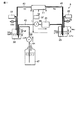
以下に本発明の一実施形態にかかるインクジェット記録装置およびインク供給方法について、図1及び図2を参照して説明する。なお、各図において適宜構成を拡大、縮小、省略して概略的に示している。インクジェット記録装置1は、インクを循環させつつインクジェットヘッド11のノズル17から図示しない記録媒体にインクを吐出して画像を形成するものであり、インク供給機構10を備えている。このインク供給機構10は、インクジェットヘッド11、インク供給源としての上流側タンク25、インクを貯留する下流側タンク30、これらを接続するとともにインクの循環路を構成する第1導管41、第2導管42、第3導管43、及びインクを循環させるインク送り機構としての循環ポンプ35(インク送り機構)、フィルタ36等を備えている。
[First Embodiment]
An ink jet recording apparatus and an ink supply method according to an embodiment of the present invention will be described below with reference to FIGS. In each drawing, the configuration is schematically illustrated by appropriately enlarging, reducing, or omitting the configuration. The ink
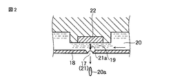
図2に示されるインクジェットヘッド11は、ノズル17を有するオリフィスプレート18を備えている。このオリフィスプレート18の背面側にノズル17に対向する圧力室19が形成されている。この圧力室19を経由してインク20が循環する。圧力室19は導管と連通する循環路よりも狭く構成されている。図2中のノズル17の対向面側に構成された圧力室19に、アクチュエータ22が設けられている。圧力室19において、このアクチュエータ22が駆動されることによって、ノズルからインク滴20aが吐出される。アクチュエータ22としては、例えばPZT等の圧電素子を用いて直接又は間接的に圧力室を変形させるものや、静電気でダイアフラムを駆動するもの、静電気で直接インクを移動させるもの、ヒーターでインクを加熱して気泡を生成し圧力を発生させるもの等が用いられるが、これらに限られない。インクジェットヘッド11は、上流ポート11aと下流ポート11bを有している。インクジェットヘッド11の上流ポート11aは、第1導管41を介して上流側タンク25に接続されている。下流ポート11bは、第2導管42を介して下流側タンク30に接続されている。このように構成されたインクジェットヘッド11において、インク20が、圧力室19を経由して、例えば図2中矢印で示すように、右から左へ循環する。
The
図1に示すように、上流側タンク25は、インクジェットヘッド11よりも上方に配置され、インク流入口25aとインク流出口25bを有し、インクを補給するためのインク供給源としての機能を有する。上流側タンク25は、上部タンク26と下部タンク27とを備え、下部タンク27の液面は大気に開放されている。上流側タンク25は第1導管41を介してインクジェットヘッド11の上流ポート11aに接続されている。上部タンク26は、交換可能なボトルである。上部タンク26のインクがなくなった場合、ユーザは上部タンク26をインク充填済みの新しいボトルと交換する。上部タンク26と下部タンク27とは通気パイプ28及びインク補給パイプ29を介して接続されている。上記インクジェットヘッド11からインクが消費されると、これに伴い下部タンク27の液面が下がり、通気パイプ28の下端が下部タンク27の液面から離れる。このとき、下端が露出した通気パイプ28を伝って空気が上部タンク26へ導入される。上部タンク26においてこの空気に押し出されたインクが、インク補給パイプ29を通って下部タンク27へ落ちると、下部タンク27の液面が上昇する。この上昇により、下部タンク27の液面が通気パイプ28の下端まで達すると、通気パイプ28が閉塞されることにより上部タンク26への空気の流入は止まり、インクの補給が停止される。こうして、下部タンク27の液面が制御されつつインクの補給が行われる。
As shown in FIG. 1, the
なお、インクジェットヘッド11のインク室のノズル17近傍つまり圧力室19の適正圧力(但し、アクチュエータがインク吐出動作のために発生する高周波成分を除く平均値)の設定範囲に余裕がある場合には、液面の高さは厳密でなくてもよいため、断面積が大きく浅い容器を上流側タンク25として用いて、体積変化に対する液面高さ変化を抑えることができる。その場合には、ユーザは上流側タンク25のインクが減った場合に、上流側タンク25に直接インクを補給してもよく、交換可能なボトルの構成を省略できる。
In the case where there is a margin in the setting range of the appropriate pressure in the vicinity of the
上流側タンク25のインクは第1導管41を介してインクジェットヘッド11の上流ポート11aへ供給される。第1導管41には、循環路を開閉可能なバルブV1(開閉機構)が設けられている。バルブV1はインクの供給を止める場合に閉じられるが、通常動作中は開放されている。
The ink in the
下流側タンク30は、インク流入口30aとインク流出口30bを有するインクタンクであり、インクを貯留するとともに圧力源としての機能を有する。下流側タンク30は、インクジェットヘッド11よりも下方に配置されている。インク流入口30aは第2導管42を介してインクジェットヘッド11の下流ポート11bに接続されている。インク流出口30bは、循環ポンプ35及びフィルタ36を備える第3導管43を介して上流側タンク25に接続されている。循環ポンプ35は下流側タンク30のインクを吸い上げ、フィルタ36で濾過し、第3導管43を介して上流側タンク25にインクを汲み上げることで、インク20を循環させる機能を有する。循環ポンプ35は、例えばチューブポンプのように、停止時に閉じる構造である。ダイアフラムポンプと逆止バルブを直列にして同じ機能を実現しても良い。なお、循環ポンプ35の制御方法は例えばON/OFF制御や速度制御等により行われる。
The
下流側タンク30は上部に空気層を有している。この空気層の上部に、開閉可能なバルブV2(圧力調整機構)を備えている。このバルブV2が制御部37により開閉されることで、選択的に、下流側タンク30の液面を大気圧に開放し、あるいは密閉することが可能となっている。さらに、下流側タンク30には二つの液面センサS1、S2(液面検出器)が設けられている。液面センサS1、S2は、タンク内のインクの液面がそれぞれ予め設定された第1水位および第2水位に達したか否かを検知する機能を有する。液面が第1水位の高さにあるとき、下流側タンク30の空気層の体積はVであり、液面が第2水位の高さにあるとき、下流側タンク30の空気層の体積はV+ΔVである。
The
これら、上流側タンク25、下流側タンク30、第1導管41、第2導管42、第3導管43及び圧力室19の内部は互いに連通し、循環路40を形成している。さらに、各大気開放部には異物の混入を防ぐための図示しないエアフィルタが設けられている。
The
インクが蒸発し易い場合には、各大気開放部に蒸発を防ぐ迷路などの機構を設けても良い。 If the ink is likely to evaporate, a mechanism such as a maze that prevents evaporation may be provided in each atmosphere opening portion.
循環ポンプ35の流量は、例えば予定される最大循環流量の120%に設定されている。上流側タンク25の液面とインクジェットヘッド11のオリフィスプレート18の面の高低差はHu、下流側タンク30の液面とインクジェットヘッド11のオリフィスプレート18の面の高低差は、Hlである。
The flow rate of the
上流側タンク25内における第1導管41の先端からインクジェットヘッド11のインク室のノズル17近傍までの流路抵抗、すなわち、上流側流路の流路抵抗をRuとする。また、インクジェットヘッド11のインク室のノズル17近傍から下流側タンク30内における第2導管42の先端までの流路抵抗、すなわち下流側流路の流路抵抗をRlとする。ここでRu、Rlは、以後の説明を簡単にするために、インクジェットヘッド11の内部の流路抵抗を含むものとする。
The flow path resistance from the tip of the
なお、本実施形態では各タンク25,30の断面積が十分大きいので、それぞれのタンク内の液面から各導管41、42の接続点までの流路抵抗は普通無視できる。仮に無視できない場合は各々Ru、Rlに加算して考えれば良い。
In this embodiment, since the cross-sectional areas of the
インクジェットヘッド11が内部の循環流路の中間点に分岐を持っていて分岐の先にノズル17を有する場合、Ruは上流側タンク25からこの分岐点までの流路抵抗、Rlは分岐点から下流側タンク30までの流路抵抗であると考えれば良い。
When the
Rl,Ruの値は流路の物理的形状で決まる定数とインクの粘度との積である。ここでは、インクは比重ρの不揮発性オイルインクであるものとする。重力加速度はg、大気圧はPatmとする。 The values of Rl and Ru are products of a constant determined by the physical shape of the flow path and the viscosity of the ink. Here, it is assumed that the ink is a non-volatile oil ink having a specific gravity ρ. Gravitational acceleration is g, and atmospheric pressure is Patm.
なお、ここでは吐出流量が循環流量に比べて十分小さいものとする。この場合、インク供給機構10やインクジェットヘッド11内の圧力損失の値は吐出流量よりも循環流量に大きく左右されることになる。各インクジェットヘッド11の下端のノズル17付近の循環流に起因する動圧は、一般には十分小さく、無視できる。また、このようなインク供給機構10ではレイノルズ数は普通、十分小さく、乱流の影響は無視できる。
Here, it is assumed that the discharge flow rate is sufficiently smaller than the circulation flow rate. In this case, the value of the pressure loss in the
次にこのインクジェット記録装置1における初期充填の動作を説明する。
インクが上流側タンク25に供給された初期状態において、バルブV1を開状態とし、循環ポンプ35を停止させる。この状態でバルブV2を開状態とすると、インクは上流側タンク25から第1導管41、インクジェットヘッド11、第2導管42を経由して下流側タンク30に流入する。
Next, the initial filling operation in the
In the initial state where the ink is supplied to the
このとき、図示しない密閉キャップによってノズル17の先端を初期充填が終わるまで密閉することにより、インクがインクジェットヘッド11のノズル17から流出するのを防ぐことができる。また、圧力ρgHuが小さく、ノズル17の直径が小さく、かつオリフィスプレート18の表面にインクが付着していないという条件がそろっている場合には、キャップを使用しなくてもインクはノズル17から流出しないので、このような場合には密閉キャップを省略できる。
At this time, it is possible to prevent the ink from flowing out from the
インクが下流側タンク30に溜まり、液面センサS1により、液面が低水位基準である第1水位を超えたことを検知すると、この検知結果に応じた制御部37の制御により、循環ポンプ35が作動し、インクが下流側タンク30から上流側タンク25に向かって送られる。以後、液面が第1水位を超えている間は循環ポンプ35が作動する。なお、循環ポンプ35の作動によって上流側タンク25の液面は僅かに上昇するが、この変化は十分小さいため無視できる。
When ink accumulates in the
この状態において、インクが、上流側タンク25から、第1導管41を含む上流側流路、インクジェットヘッド11、第2導管42を含む下流側流路、循環ポンプ35、フィルタ36、第3導管43で構成される帰還流路を介して、再び上流側タンク25に戻る循環流が生じている。循環ポンプ35は間欠的に作動している。この場合の循環流量はHu,Hl,Ru,Rlとρ,gによって定まり、その値をQ1とすれば、Q1=ρg(Hu+Hl)/(Ru+Rl)である。
In this state, ink flows from the
また、ノズル17近傍の圧力も、Hu,Hl,Ru,Rlとρ,gによって定まる。この値をPn1(ゲージ圧)とすれば、Pn1=ρgHu −ρg(Hu+Hl)(Ru/(Ru+Rl))である。
The pressure near the
このとき、Pn1は、例えばノズル17からインクが溢れないように、例えば−0.1kPa程度に設定される。また、Q1は、予定の循環流量よりも小さな値に設定される。この状態を低速循環状態とする。このときQ1が予定の循環流量よりも小さいので、下流側タンク30の位置をあまり下げなくてもよい。したがって、物理的な制約がある場合でもインクジェット記録装置1を容易に構成できる。
At this time, Pn1 is set to, for example, about −0.1 kPa so that ink does not overflow from the
次に、循環流量を大きくして、ノズル17近傍の圧力をインク吐出に適する値まで低くする(絶対値を大きくする)動作について説明する。
Next, an operation of increasing the circulating flow rate and reducing the pressure in the vicinity of the
下流側タンク30の空気層を大気圧に解放していたバルブV2を閉じ、下流側タンク30内の液面が、第2水位となるまで、循環ポンプ35を作動させる。液面センサS2によって、下流側タンク30の液面が第2水位を下回ったことが検知されたら、循環ポンプ35を停止させる。以後循環ポンプ35は液面が第2基準を超えている間だけ作動させる。このとき、下流側タンク30の液面はΔHlだけ低下し、上流側タンク25の液面はΔHuだけ上昇するがこれらの値はHl,Huと比べて十分小さい。ここで、ΔHl, ΔHu分のポテンシャルヘッドの変化は十分小さいため無視できる。
The valve V2 that has released the air layer of the
バルブV2を閉じた時点では、下流側タンク30の空気層は体積Vであったが、この状態から液面を下げたので下流側タンク30の空気層はV+ΔVに増大した。したがって、下流側タンク30の空気層は減圧されている。この状態での下流側タンク30の空気層のゲージ圧をPL(負値)とすれば、PL=−ΔV(V+ΔV)Patmである。ここでPatmは大気圧である。
At the time when the valve V2 was closed, the air layer in the
このときの循環流量をQ2とすれば、Q2=(ρg(Hu+Hl)−PL)/(Ru+Rl)= Q1 + (−PL/(Ru+Rl))となる。すなわち、循環流量はQ1よりも(−PL/(Ru+Rl))だけ増大する。 If the circulation flow rate at this time is Q2, Q2 = (ρg (Hu + Hl) −PL) / (Ru + Rl) = Q1 + (− PL / (Ru + Rl)). That is, the circulation flow rate is increased by (−PL / (Ru + Rl)) from Q1.
また、ノズル17近傍の圧力をPn2(ゲージ圧)とすれば、Pn2=ρgHu - (ρg(Hu+Hl)−PL)(Ru/(Ru+Rl)) = Pn1+PL(Ru/(Ru+Rl)となる。すなわち、ノズル17近傍の圧力はPn1よりも−PL(Ru/(Ru+Rl)の大きさだけ負圧側にシフトする。
If the pressure near the
ここで、Q2を目標の適正循環流量に設定し、Pn2を適正なノズル17近傍の圧力に設定すれば良い。なお、循環流量の適正値は、例えば印刷時の最大流量の1倍〜20倍の範囲で設定する。また、ノズル近傍の圧力の適正値は例えば0以下、かつ−3kPa以上の範囲で設定する。
Here, Q2 may be set to a target appropriate circulation flow rate, and Pn2 may be set to an appropriate pressure in the vicinity of the
なお、循環を停止し、かつ、ノズル17近傍の圧力を適正範囲内に保ったまま待機させる場合は次のように動作させる。まずバルブV2を開状態とし、循環ポンプ35の作動条件を液面センサS1に戻し、基準水位を第1水位とすることで、高速循環状態から低速循環状態に移行する。次にバルブV1をゆっくり閉じる。この結果、ノズル17近傍の圧力は徐々に低下する。このとき、ノズル17近傍の圧力は負圧なので絶対値は大きくなる。このときのノズル17近傍の圧力の収束値をPn3(ゲージ圧) とすれば、Pn3=−ρgHlとなる。Pn3は例えば−3kPaに設定される。
When the circulation is stopped and the pressure in the vicinity of the
本実施形態にかかるインクジェット記録装置1またはインク供給機構10は、以下に掲げる効果を奏する。すなわち、循環ポンプ35とタンクの内圧の調整により、循環流量やノズル近傍の圧力を適正値に調節することができる。したがって、インクジェットヘッド11やタンク25,30の配置に制約がある場合にも適正な流量や圧力を確保することが可能となる。すなわち、下流側タンク30の位置が変わってインクジェットヘッド11のオリフィスプレート18面に対する下流側タンク30の液面のポテンシャルヘッドが変わっても、これに応じて液面センサS1、S2の高さの差を変え、密閉時の下流側タンク30の空気層の圧力を調整することで、所望の循環量とノズル圧力を得ることができるため、下流側タンク30の位置を構造上有利な場所に配置し易い。
The ink
また、仮に下流側タンク30がインクジェットヘッド11よりも上に位置したとしても、液面センサS1,S2の高さの差を大きく取り、下流側タンク30の空気層の負圧を適正な値に設定すれば、所望の循環量とノズル圧力を得ることが可能である。
Even if the
さらに、状況に応じて循環流量を調整し、低速循環状態と高速循環状態とを使い分け、かつ、ノズル近傍の圧力を適正に維持することにより、循環式システムの利益を享受することができる。すなわち、インクが滞留して沈殿する危険が少なく、システムの温度も安定させるとともに、又循環中にろ過や脱気、脱泡を行えば循環によってインクの性質をよりインクジェットの飛翔に適したものに改質でき、万が一どこかで気泡が発生しても下流側タンク30まで押し流して気泡を開放可能である程度に循環流量を大きくすることができる。また、一方で、循環流量が大きすぎないように設定することで、負圧部での空気の混入や気液界面での泡立ちを起こす恐れや、又混入してしまった気泡やパーティクル等がヘッドのノズル近くまで送られてしまうのを防ぎ、流路の狭い所をインクが通過する際にインクにシェアストレスが加わりインクの安定性に影響が出るのを防止することができる。
Furthermore, by adjusting the circulation flow rate according to the situation, selectively using the low-speed circulation state and the high-speed circulation state, and maintaining the pressure in the vicinity of the nozzle appropriately, the benefits of the circulation system can be enjoyed. In other words, there is little risk of ink stagnation and precipitation, the system temperature is stabilized, and if filtration, deaeration, and defoaming are performed during circulation, the properties of the ink are made more suitable for inkjet flight by circulation. Even if bubbles are generated somewhere, it is possible to open the bubbles to the
[ 第2実施形態]
次に本発明の第2実施形態に係るインクジェット記録装置2について図3乃至図10を参照して説明する。各図においては適宜構成を拡大、縮小、省略して概略的に示している。なお、第1実施形態と同様の構成については説明を省略する。
[Second Embodiment]
Next, an ink
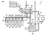
図3に示されるインクジェット記録装置2は、複数のインクジェットヘッド11〜16、インク供給源としての上流側タンク25、インクを貯留する下流側タンク30、上流側タンク25にインクを供給する供給タンク47等を備えている。
The ink
複数(ここでは6個)のインクジェットヘッド11〜16は、上記第1実施形態のインクジェットヘッド11と同様に構成されている。
The plurality (six in this case) of the inkjet heads 11 to 16 are configured in the same manner as the
上流側タンク25と供給タンク47とは、途中に循環路を開閉可能なバルブV3を有する第4導管44を介して接続されている。供給タンク47は上流側タンク25よりも上方に位置し、第4導管44は供給タンク47から上流側タンク25に向かって下方に傾斜して配されている。
The
供給タンク47は第1実施形態における上部タンク26と同様に交換式のカートリッジであってもよいし、上部からインクを注ぐ形式のタンクであっても良い。供給タンク47の内部圧力は、大気圧に開放されている。供給タンク47のインクは第4導管を通って上流側タンク25へ注がれる。
The
上流側タンク25は、上部に空気層を有している。この空気層の上部に、開閉可能なバルブV4を備えている。このバルブV4が制御部37により開閉されることで、選択的に、上流側タンク25の液面を大気圧に開放し、あるいは密閉することが可能となっている。
The
さらに、上流側タンク25には液面センサS3が設けられており、タンク内のインクの液面が予め設定された第3水位に達しているか否かを検知する機能を有する。この液面センサS3の検知結果に応じた制御部37の制御により、上記バルブV3が開閉されることで、インクの流動状態を調節可能である。これにより、上流側タンク25の下部タンクの液面が一定に維持される。
Further, the
上流側タンク25の下方に鉛直に延びる第1導管41には、循環路を開閉可能なバルブV5が設けられている。このバルブV5よりも下方における第1導管41は、内径6mmx 長さ5mmの円柱管に構成されている。この円柱管状の第1導管41は、バルブV5よりも下方において、6本に分岐し、第5導管を構成している。この6本の第5導管45はそれぞれ6個のインクジェットヘッド11〜16の上流側ポート11a〜16aに接続されている。第5導管45は、分岐部分からインクジェットヘッド11〜16の上流側ポート11a〜16aに至るまで水平または緩やかに下るように形成されており、上昇する部分がないように構成されている。
The
上流側タンク25と下流側タンク30とを接続する第2導管は、第1導管と同様に、内径6mmの円柱管状に構成されている。この第2導管にも、開閉可能なバルブV6が設けられている。さらに、第2導管は、このバルブV6の下方において6本の第6導管46に分岐している。この6本の第6導管46は、それぞれインクジェットヘッド11〜16の下流ポート11b〜16bに接続されている。第6導管46は、インクジェットヘッド11〜16の下流ポート11b〜16bから分岐部分に向かって水平に延び、または緩やかに上昇するように形成されており、下降する部分がないように構成されている。
Similar to the first conduit, the second conduit connecting the
6台のインクジェットヘッド11〜16は各々50mmの幅を有している。したがって、6台全て使用すると300mm幅の印刷が可能である。6本の第5導管45の内径と長さは、最も円柱管に近いインクジェットヘッド11に接続されるものから、最も遠いインクジェットヘッド16に接続されるものの順に、φ3x100, φ3x155, φ3x210, φ3x265, φ3x320, φ3x375mmに構成されている。6本の第6導管46の内径と長さは、それぞれ、最も円柱管に近いインクジェットヘッド11に接続されるものから最も遠いインクジェットヘッド16に接続されるものの順に、φ3x10⁶, φ3x160, φ3x214, φ3x267, φ3x321, φ3x375mmに構成されている。
Each of the six inkjet heads 11 to 16 has a width of 50 mm. Therefore, when all six units are used, printing with a width of 300 mm is possible. The inner diameters and lengths of the six
第2導管42において、バルブV6よりも上方は上流側タンク25の内部において上方に鉛直に向かって延び、その先端は空気層に開放されている。第2導管42において、分岐点よりも下方に、循環路を開閉可能なバルブV8が設けられている。バルブV8のさらに下方に位置する第2導管42の先端部分は、下流側タンク30の内部に開放されている。分岐点から下流側タンク30の内部の先端までの円柱管の長さは143mmである。
In the
下流側タンク30には二つの液面センサS4、S5が設けられている。液面センサS4、S5は、タンク内のインクの液面がそれぞれ予め設定された第4水位および第5水位に達しているか否かを検知する機能を有する。S4はS5より高い位置に設定されている。下流側タンク30は上部に空気層を有している。この空気層の上部に、開閉可能なバルブV7を備えている。このバルブV7が制御部37により開閉されることで、選択的に、下流側タンク30の液面を大気圧に開放し、あるいは密閉することが可能となっている。下流側タンク30の空気層の内圧は圧力センサ31によって測定されている。
The
下流側タンク30は、例えば断面50mm2 高さ10mmの寸胴の円筒形に構成されている。液面が第5水位にあるときには空気層体積は5mLとなる。
The
下流側タンク30と上流側タンク25とを接続する第3導管43は循環ポンプ35およびフィルタ36を備えている。下流側タンク30内のインクは、この循環ポンプ35及びフィルタ36を介して上流側タンク25へ戻される。
A
ここで、使用するインクは比重0.85、粘度10mPasの不揮発性油性インクである。各インクジェットヘッド11〜16は表面直径27μmの撥インク処理された636本のノズルを有している。各ノズルから周波数6240Hzで42pLのインクインク滴を吐出できる。一つのインクジェットヘッドの全ノズル636本が全て連続して吐出したときのインク流量は10mL/minである。 The ink used here is a non-volatile oil-based ink having a specific gravity of 0.85 and a viscosity of 10 mPas. Each of the inkjet heads 11 to 16 has 636 nozzles having a surface diameter of 27 μm and an ink repellent treatment. 42 pL ink ink droplets can be ejected from each nozzle at a frequency of 6240 Hz. The ink flow rate is 10 mL / min when all 636 nozzles of one inkjet head are ejected continuously.
各インクジェットヘッドの上流側ポート11a〜16aと下流側ポート11b〜16bの間の流路抵抗は3.85 x 10⁹ Pa・s/m3とする。また、オリフィスプレート18の表面から見た上流側の流路抵抗と下流側の流路抵抗の比は、1:0.96とする。
The flow path resistance between the
上流側第5導管45の流路抵抗は、最も円柱管に近いインクジェットヘッド11から最も遠いインクジェットヘッド16に向かって順に、5.03 x 10⁸ Pa・s/m3、7.80 x 108 Pa・s/m3、1.06 x 109 Pa・s/m3、1.33 x 109 Pa・s/m3、1.61 x 109 Pa・s/m3、1.89 x 109 Pa・s/m3となる。
The flow resistance of the upstream
下流側第6導管46の流路抵抗は、最も円柱管に近いインクジェットヘッド11から最も遠いインクジェットヘッド16に向かって順に、5.33 x 10⁸ Pa・s/m3、8.05 x 108 Pa・s/m3、1.08 x 109 Pa・s/m3、1.34 x 109 Pa・s/m3、1.61 x 109 Pa・s/m3、1.89 x 109 Pa・s/m3となる。
The flow path resistance of the downstream side sixth conduit 46 is 5.33 × 10 8 Pa · s / m 3 , 8.05 × 10 8 in order from the
バルブV5を含む上流側第1導管41の流路抵抗は、3.77 x 10⁶ Pa・s/m3であり、バルブV8を含む下流側第2導管42の分岐点から下流側タンク30の内部の先端までの流路抵抗は、4.72 x 107 Pa・s/m3、である。
The flow resistance of the upstream
上流側タンク25の液面はインクジェットヘッド11から16のオリフィスプレート18の表面よりも12mm高く位置している。これによる水頭圧は100Paである。下流側タンク30の液面はインクジェットヘッドのオリフィス面よりも120mm低く位置している。これによる水頭圧は1kPaである。
The liquid level of the
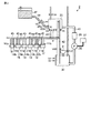
次に、このインクジェット記録装置に初期状態からインクを充填する動作までについて説明する。なお、図3乃至図7において、インクが充填されている部分を斜線のハッチングで示している。図3に示す初期状態でインクは供給タンク47内に収容されている。この状態からバルブV4,V5,V6,V8を開き、次いでバルブV3を開くと、図4に示すように、インクは上部タンクから下部タンクへ降りてくる。この間V7は閉じておく。インクは図5に示すように、供給タンク47から第4導管44、上流側タンク25、第1導管41、インクジェットヘッド11〜16、第2導管42を通って下流側タンク30へと流れ落ちてくる。なお、液面センサS3において、上流側タンク25の液面が第3水位の高さを上回っている間にはバルブV3が閉じられ、液面が調節される。
Next, the operation from the initial state to the ink filling operation of the ink jet recording apparatus will be described. In FIGS. 3 to 7, the portion filled with ink is indicated by hatching. Ink is contained in the
第2導管42のインクがバルブV6に達したらV6を閉じV7を開く。ここで、インクがバルブV6に達したかどうかの判断は供給開始からの時間で行うことも出来るが、下流側タンク30の圧力計31(圧力検出器)の値によっても判断できる。即ち圧力計31の読み値が下流側タンク30からバルブV6までの高さのインクのポテンシャル圧力と一致したらインクがほぼバルブV6の位置に達したと判断できる。この実施形態では第2導管42のインクがバルブV6を超えて上流側タンク25の空気層に溢れ出しても特に問題は無く、タイミングに関して高い精度は要求されない。
When the ink in the
循環ポンプ35は下流側タンク30の液面が第4水位の位置を上回ったら作動させるように設定される。図6に示すように、インクが下流側タンク30に溜まり、第4水位を超えると、設定しておいた条件が成立するので、循環ポンプ35が作動する。循環ポンプ35は、下流側タンク30のインクをフィルタ36と帰還流路を構成する第3導管43を介して上流側タンク25に汲み上げる。この際上流側タンク25のインクは第3水位よりも僅かに上がる場合があるが、循環系の圧力分布に与える影響は小さく、無視できる。この状態はインクがゆっくり循環する低速循環状態である。
The
上記動作の間、インクジェットヘッド11〜16の各ノズル17にはまず正圧が与えられ、下流側にインクが充填されるに従ってその値は減少して行く。与えられる正圧の最大値は約100Paである。この正圧によってインクが垂れることを防ぐには、この間に、各インクジェットヘッド11〜16の各ノズル17を、図示しないキャップで密閉しておけば良い。他に、後で説明するように、適正なメニスカスを維持する条件を保つことで、キャップが無くても各インクジェットヘッド11〜16のノズル17からインクが垂れることを防ぐことができる。
During the above operation, a positive pressure is first applied to each
このときの循環流量を計算すると、6台のインクジェットヘッド11〜16の合計で62mL/minである。また、各インクジェットヘッド11〜16毎の循環流量は、円柱管に近いインクジェットヘッド11から順に、夫々13mL/min、12mL/min、11mL/min、10mL/min、9mL/min、8mL/minとなる。ノズル17近傍の圧力は全インクジェットヘッド11〜16でほぼ等しく−434Paである。この状態でも印刷は可能である。
When the circulation flow rate at this time is calculated, the total of the six inkjet heads 11 to 16 is 62 mL / min. Further, the circulation flow rate for each of the inkjet heads 11 to 16 is 13 mL / min, 12 mL / min, 11 mL / min, 10 mL / min, 9 mL / min, and 8 mL / min, respectively, in order from the
次に、前述したインク循環式の利点を享受するために、循環速度を6台のインクジェットヘッド11〜16の合計で180mL/minまで上げる手順について説明する。図7に示すように、バルブV7を閉じ、下流側タンク30を密閉するとともに、圧力計31が−2110Paになるまで循環ポンプ35を作動させる。圧力計31が−2110Paを下回っている間だけ循環ポンプ35を作動させるように設定しておく。このとき、下流側タンク30内の空気層は減圧によって膨張しているがその分の液面は0.2mm程度僅かに低下する。この液面変化によるポテンシャル圧力の変化は十分小さいため無視できる。なお、この実施形態の条件は、第1実施形態のように液面で管理するよりも、直接圧力を測定して管理する方が望ましいと言える。もちろん、液面を精度良く検出できる場合には、第1実施形態のように液面で管理しても良いし、下流側タンク30の形状が異なり、例えば空気層の体積がもっと大きければ圧力管理よりも液面管理の方が有利となる場合もあるため、どちらを用いても良い。この状態は、インクが180mL/minで循環する高速循環状態である。
Next, a procedure for increasing the circulation speed to 180 mL / min in total for the six inkjet heads 11 to 16 in order to enjoy the advantages of the ink circulation system described above will be described. As shown in FIG. 7, the valve V7 is closed, the
この時の各ヘッド11〜16毎の循環流量は、円柱管に近いインクジェットヘッド11から順に、夫々、38mL/min、34mL/min、31mL/min、28mL/min、26mL/min、24mL/minとなる。また、ノズル17近傍の圧力は、全ヘッド11〜16においてほぼ等しく−1.46kPaである。
At this time, the circulation flow rate for each of the
以上、各インクジェットヘッド11〜16がインクを吐出しない場合やごく僅かだけ吐出する場合について説明したが、インクの吐出を行うと上流側の流量が増大し、下流側の流量が減少するので、ノズル17近傍の圧力はより負圧側にシフトする。各インクジェットヘッド11〜16が最大吐出を行った場合には、ノズル17近傍の圧力(但し、アクチュエータがインク吐出動作のために発生する高周波成分を除く平均値)は最も負圧側に動く。その時の各ヘッド11〜16のノズル17近傍の圧力を計算すると、円柱管に近いヘッド11から順に、夫々−1.68kPa、−1.7kPa、−1.72kPa、−1.73kPa、−1.77kPa、−1.79kPaとなった。これらのノズル位置の圧力は、いずれも適正値の範囲内である。
As described above, the case where each of the inkjet heads 11 to 16 does not discharge ink or the case where only a small amount of ink is discharged has been described. However, when ink is discharged, the upstream flow rate increases and the downstream flow rate decreases. The pressure in the vicinity of 17 shifts more toward the negative pressure side. When each of the inkjet heads 11 to 16 performs maximum ejection, the pressure in the vicinity of the nozzle 17 (however, the average value excluding high-frequency components generated by the actuator for the ink ejection operation) moves to the most negative pressure side. When the pressures in the vicinity of the
なお、以上説明した動作に液面センサs5は必ずしも必要でないが、このセンサは異常検出に用いることができる。ここで、液面センサS5を例えばS4の位置よりも1mm下に設定する。正常に動作している場合には、循環中に液面がS5を下回ることは無いはずであるから、もし下流側タンク30の液面が液面センサS5の高さを下回った場合には、異常として上流側タンク25からヘッドを経由して下流側タンク30に至るインクの通過経路のどこかにインク漏れがあることを検出できる。
The liquid level sensor s5 is not necessarily required for the operation described above, but this sensor can be used for abnormality detection. Here, the liquid level sensor S5 is set, for example, 1 mm below the position of S4. When operating normally, the liquid level should not fall below S5 during circulation, so if the liquid level in the
ここで、インク滴下防止の条件について説明する。一般に、循環供給系では、オリフィスプレート18の表面の高さから見た上流側のインク供給源の単位体積あたりエネルギー(上流側タンク25の液面の静圧とポテンシャル圧力の和)は、通常インクジェットヘッドのインク吐出に適した圧力P1よりも上流側流路抵抗×循環流量分だけ大きい。
Here, conditions for preventing ink dripping will be described. In general, in the circulation supply system, the energy per unit volume of the upstream ink supply source as viewed from the height of the surface of the orifice plate 18 (the sum of the static pressure of the liquid level of the
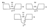
従って、循環中、メニスカスが図8(a)に示すような凹形状の状態にあったとしても、もし何らかの理由で循環が停止すると、メニスカスの負圧は減少し、正圧に転じて図8(b)に示すようにノズル先端から突出して盛り上がる。 Therefore, even if the meniscus is in a concave shape as shown in FIG. 8A during circulation, if the circulation stops for some reason, the negative pressure of the meniscus decreases and turns to positive pressure. As shown in (b), it protrudes from the nozzle tip and rises.
立ち上げ初期の循環を開始前の他、待機状態で電力を節約したり、緊急停止のために循環を止める場合などにこの様な状態になる。メニスカスの盛り上がり程度はノズル近傍のインク圧力に依存する。即ち本実施形態のような循環供給系では、上流側タンク25の液面とオリフィスプレート18の表面の水頭差に依存する。
In addition to starting circulation at the initial stage of startup, such a state occurs when power is saved in a standby state or when circulation is stopped for an emergency stop. The degree of rise of the meniscus depends on the ink pressure near the nozzle. That is, in the circulation supply system as in the present embodiment, it depends on the water head difference between the liquid level of the
このノズル近傍の圧力が大きいと図8(b)の状態から、さらにメニスカスが盛り上がり、図8(c)状態となる。ノズル近傍の圧力がP2に達すると、ノズル17の先端面でインク滴が維持できなくなり、インク20が滴下し、あるいはノズル17の先端を越えてオリフィスプレート18に広がった後滴下する。
When the pressure in the vicinity of the nozzle is large, the meniscus rises further from the state shown in FIG. 8B, resulting in the state shown in FIG. When the pressure in the vicinity of the nozzle reaches P2, the ink droplet cannot be maintained on the tip surface of the
待機時などの場合にインクが滴下することは、余計なインクを消費し、また周囲を汚すため好ましくない。従ってオリフィスプレート18の表面の高さから見た上流側のインク供給源の単位体積あたりエネルギー(上流側タンク25液面の静圧とポテンシャル圧力の和)はP2よりも小さくすると良い。例えば第2実施形態では、上流側タンク25の液面の静圧は0(大気圧)、ポテンシャル圧力は100Paなので、オリフィスプレート18の表面高さから見た上流側のインク供給源の単位体積あたりエネルギーは100Paである。一方P2は実測で約2kPa以上である。したがって、後述するようにオリフィスプレート18の表面状態を綺麗にしておけばインクの滴下が防止される。
It is not preferable that ink drops during standby or the like because it consumes extra ink and stains the surroundings. Therefore, the energy per unit volume of the upstream ink supply source as viewed from the height of the surface of the orifice plate 18 (the sum of the static pressure and the potential pressure of the
循環時のメニスカス圧力Pnを維持しつつ上流側インク供給源のオリフィスプレート18面の換算圧力を下げるには、上流側流路抵抗を小さくすれば良い。この為には上流側のインク供給源をインクジェットヘッド11になるべく近く設置すれば良く、第2実施形態の構造はそのように設定されている。
In order to reduce the converted pressure on the
ノズル17の近傍にインクの付着が無く綺麗にメンテナンスされているとき、インク20は図8(c)の状態になるまでノズル17から溢れ出て滴下することは無い。従って、インク充填動作などに先立ってノズル17の表面を綺麗にメンテナンスし、あるいはインクジェットヘッド11を乾燥させておくことで、インクの滴下を防ぎ、インクをノズル17から滴下させることなくP2までの静圧が許容される。
When there is no adhesion of ink in the vicinity of the
一方、ノズル17近傍のインク圧力がP2よりも小さくても、例えばワイプ等により凸形状になった図8(b)のメニスカス21を壊してしまうと、図9(a)のようにオリフィスプレート18上にインクが広がり、図9(b)のようにP2より小さい圧力P3でインクが滴下する。
On the other hand, even if the ink pressure in the vicinity of the
また、図10(a)に示すように、ノズル17からオリフィスプレート18の表面までの距離が比較的近い場合は、圧力P3’でインク20はノズルプレート側面に回りこむ。また、図10(b)に示すように、オリフィスプレート18が表面にノズル17穴よりも大きい凹部を持つ形状ならば、圧力P3’’以上で普段インクが付着しないはずのオリフィスプレート18の最表段にインクが流れ出す。以上のようにインクが流れ出すことは、周囲を汚すため好ましくない。従って上流側インク供給源のノズル面換算圧力をP3、P3’又はP3’’以下に抑えておくことがより望ましい。P1,P2,P3の大きさはノズル周辺の形状、ノズル材料とインクの接触角、インクの表面張力によって決まり、計算または実験で求められる。ここで、P2>P3’’>P3, P3’>0>P1である。
Further, as shown in FIG. 10A, when the distance from the
本実施形態においても上述した第1実施形態にかかるインクジェット記録装置1と同様の効果が得られる。さらに、本実施形態にかかるインクジェット記録装置2では、インクジェットヘッドが複数の場合にも対応可能である。
Also in this embodiment, the same effect as the ink
[第3実施形態]
次に本発明の第3実施形態に係るインクジェット記録装置について図11乃至図16を参照して説明する。上記第1実施形態または第2実施形態と同様の構成については説明を省略する。なお、各図において適宜構成を拡大、縮小、省略して概略的に示している。
[Third Embodiment]
Next, an ink jet recording apparatus according to a third embodiment of the present invention will be described with reference to FIGS. The description of the same configuration as the first embodiment or the second embodiment is omitted. In each drawing, the configuration is schematically illustrated by appropriately enlarging, reducing, or omitting the configuration.
図11に示されるインクジェット記録装置3は、インクジェットヘッド11、インクジェットヘッド11に供給するインクを貯留する上流側タンク25、インクを貯留する下流側タンク30、下流側タンク30にインクを供給する供給タンク47、これらを接続するとともにインクの循環路を構成する導管41〜44、及びインクを循環させるインク送り機構としての循環ポンプ35を備えている。
An inkjet recording apparatus 3 shown in FIG. 11 includes an
インクジェットヘッド11は、上記第1実施形態のインクジェットヘッド11と同様に構成されている。
The
上流側タンク25及び下流側タンク30はいずれもインクジェットヘッド11よりも低く配置されている。上流側タンク25は第1導管41を介してインクジェットヘッド11の上流ポート11aと接続されている。下流側タンク30は第2導管42を介してインクジェットヘッド11の下流ポート11bと接続されている。上流側タンク25と下流側タンク30とは第3導管43を介して接続されている。この第3導管43は、インク送り機能を有する循環ポンプ35及びフィルタ36を備えている。下流側タンク30の内部は、第4導管44を介して、下流側タンク30に供給されるインクを保持する供給タンク47に接続されている。この第4導管44の途中には、インク送り機能を有する供給ポンプ38が備えられている。
Both the
供給タンク47は交換式のカートリッジであってもよいし、上部からインクを注ぐ形式のタンクであっても良い。供給タンク47の内部圧力は、大気圧に開放されている。供給タンク47の内部のインクは供給ポンプ38を介して第4導管44を通って下流側タンク30へ注がれる。
The
上流側タンク25は断面積変化のない円柱状に構成されている。上流側タンク25は、二つの液面センサS6、S7が設けられている。液面センサS6、S7は、タンク内のインクの液面がそれぞれ予め設定された第6水位および第7水位に達したか否かを検知する機能を有する。第7水位より上の空気層の高さはhauに構成されている。上流側タンク25の空気層は開閉可能なバルブV9を介して大気に接続されている。このバルブV9が制御部37により開閉されることで、選択的に、上流側タンク25の液面を大気圧に開放し、あるいは密閉することが可能となっている。さらに、上流側タンク25には、上流側タンク25の内部の空気層の圧力を測定可能な圧力計32が設けられている。
The
下流側タンク30は断面積変化のない円柱状に構成されている。下流側タンク30は、二つの液面センサS8、S9が設けられている。液面センサS8、S9は、タンク内のインクの液面がそれぞれ予め設定された第8水位および第9水位に達したか否かを検知する機能を有する。液面センサS8より上の空気層の高さはhalに構成されている。下流側タンク30の空気層は開閉可能なバルブV10を介して大気に接続されている。このバルブV10が制御部37により開閉されることで、選択的に、下流側タンク30の液面を大気圧に開放し、あるいは密閉することが可能となっている。さらに、下流側タンク30には、下流側タンク30の内部の空気層の圧力を測定可能な圧力計31が設けられている。
The
これらの複数のタンク25,30,47、ヘッド11及び導管41〜44によって、インクを循環できる循環系が構成されている。
The plurality of
第7水位と第8水位は高さが同じで、ノズルより高さh下方に位置している。第9水位は第8水位よりも−Δhl(Δhlは負値)下方に位置している、第6水位は第7水位よりもΔhu上方に位置している。 The seventh water level and the eighth water level have the same height and are located below the nozzle by height h. The ninth water level is located −Δhl (Δhl is a negative value) below the eighth water level, and the sixth water level is located Δhu above the seventh water level.
バルブV9と圧力計32、バルブV10と圧力計31に接続される部分の内部体積は十分小さいものとする。仮に上流側タンク25、下流側タンク30の上部に断面積変化があるか、もしくはバルブV9と圧力計32、バルブV10と圧力計31に接続される部分の内部体積が無視できない場合は、体積が同じで断面積変化のない円柱状のタンクに置き換えて考えて、hau、halを補正すればよい。
It is assumed that the internal volume of the portion connected to the valve V9 and the
循環ポンプ35、供給ポンプ38はともに、例えばチューブポンプのように、停止時に閉じる構造である。ダイアフラムポンプと逆止バルブを直列にして同じ機能を実現しても良い。なお、循環ポンプ35や供給ポンプ38の制御方法は例えばON/OFF制御や速度制御等により行われる。
Both the
ここで、本実施形態におけるインクの比重は0.85、h=120mmである。上流側タンク25からオリフィスプレート18の表面までの流路抵抗Ruは、Ru = 4 x 10⁹ Pa・s/m3であり、らオリフィスプレート18の表面から下流側タンク30までの流路抵抗Rlは、Rl = 4 x 10⁹ Pa・s/m3である。hau=51mm, hal=49mm、Δhu=1mm, Δhl=−1mmとなっている。ここでは、上流側タンク25の断面積と下流側タンク30の断面積は等しい。大気圧は101kPaであり、重力加速度は9.8m/s2である。
Here, the specific gravity of the ink in this embodiment is 0.85 and h = 120 mm. The flow path resistance Ru from the
次に、このインクジェット記録装置3に初期状態からインクを充填する動作までについて説明する。初期状態でインクは供給タンク47内に収容されている。ここで、バルブV10を開くとともに、供給ポンプ38を作動させると、インクが下流側タンクに送られ、下流側タンク30にインクが貯留される。ここで、バルブV9を開いて循環ポンプ35を作動させると、下流側タンク30のインクは、フィルタ36を介して上流側タンク25に流れ込む。このとき、各液面センサS6、S7、S8、S9を監視しながら循環ポンプ35と供給ポンプ38を適宜駆動することで、水位を調整することができる。ここで、上流側タンク25の液面を第7水位に、下流側タンク30の液面を第8水位となるよう調節する。この状態で、上流側タンク25の液面高さと下流側タンク30の液面高さは一致している。
Next, the operation from the initial state to the ink filling operation of the ink jet recording apparatus 3 will be described. Ink is stored in the
次にバルブV9とバルブV10を閉じて循環ポンプ35をゆっくり駆動する。これに伴い、インクは第1導管41、インクジェットヘッド11、第2導管42の順で流れ、循環系に充填される。
Next, the valve V9 and the valve V10 are closed, and the
この状態で、循環ポンプ35を停止させる。循環流が止まったら、バルブV9、バルブV10を開放する。ここで、第1導管41、インクジェットヘッド11及び第2導管42を含む循環系に充填した分だけインクの総量が減っているため、再度、各液面センサS6、S7、S8、S9を監視しながら適宜供給ポンプ38と循環ポンプ35を駆動して各液面を第7水位及び第8水位の位置に合わせる。
In this state, the
この状態で、循環は停止しており、インクジェットヘッド11の液面は大気開放面よりもh=120mmだけ上に位置する。したがって、インクジェットヘッドのノズル近傍には−ρgh=−1kPaの負圧が印加されている。この負圧は、非吐出時のインク圧力としては適切な値である。
In this state, the circulation is stopped, and the liquid level of the
次にインクを循環させる動作について説明する。上記インクが充填した状態において、バルブV9,V10を閉じ、上流側タンク25の液面が液面センサS6の位置になるまで循環ポンプ35を駆動する。その後は液面センサS6の位置を維持するように循環ポンプ35を制御する。このとき上流側タンク25の空気は圧縮されるため、圧力が上がる。また、下流側タンク30の空気は膨張するため、圧力が下がる。ここで、上流側タンク25の断面積は一様であるので、空気層の体積は空気層の高さに比例する。従って上流側タンク25の空気層のゲージ圧Pauは、Pau=Δhu/(hau−Δhu)x101kPa=1/(51−1)x101kPa=2.02kPaとなる。この時上流側タンク25内のインク量は、Δhuに上流側タンク25の断面積を掛けた体積だけ減少するが、ポンプ38が停止していれば循環経路内のインクの総量は変わらないので下流側タンク30のインク量はこれと同じだけ増大する。ここでは上流側タンク25と下流側タンク30の断面積が等しいので、Δhl=−Δhu=−1mmである。下流側タンク30の断面積が一様であるので、空気層の体積は空気層の高さに比例する。従って下流側タンク30の空気層のゲージ圧Palは、Pal=Δhl/(hal−Δhl)x101kPa=−1/(49+1)x101kPa=−2.02kPaである。
Next, the operation for circulating the ink will be described. In a state where the ink is filled, the valves V9 and V10 are closed, and the
上流側タンク25の液面は1mm上昇し、下流側タンク30の液面は1mm低下しているので、17Paのポテンシャル圧力が循環方向に働いている。上流側タンク25と下流側タンク30の差圧は4.04 kPaであるので、循環流量は、(4040+17 Pa) / 8 x 10⁹ Pa・s/m3 x 1003 x 60 = 30.4 mL/min である。ノズル17近傍の圧力Pnは,Pau−ρg(h−Δhu)と、Pal−ρg(h−Δhl)をRuとRlで分圧したものであるが、ここではRu=Rl, Δhu=−Δhlなので、Pn = −ρgh = −1 kPaとなる。これは、循環開始前と同一であり、適正値の範囲内である。
Since the liquid level of the
また、インクジェットヘッド11がインクを吐出すると上流側の流量が増大し、下流側の流量が減少するので、Pnは−1kPaよりも負圧側に振れる。この圧力変化は、上流側流路抵抗と下流側流路抵抗を並列にして吐出流量のインクを流した場合の圧力損失と等価であると考えることができる。インクジェットヘッド11の最大吐出量Qiを第2実施形態と同じ10mL/minとすれば、圧力損失Plossは、Ploss = Ru*Rs/(Ru+Rs) * Qi = 2x10⁹ Pa・s/m3 x 10mL/min x 1/(1003x60) = 333 Paとなるので、ノズル17近傍の圧力(但し、アクチュエータがインク吐出動作のために発生する高周波成分を除く平均値)は最大吐出時に約−1.33kPaまで低下する。この値は適正値の範囲内である。
Further, when the
ここで、流量がさらに大きく、吐出時のPnが負圧側に負圧側に振れすぎる場合には、RuとRlを小さくする。例えば、導管を太く又は短くすることによりRuとRlを小さくすることができる。インクジェットヘッド11が吐出を続けると循環系のインク総量が減少するので、供給ポンプ38を駆動してインクを補充する。例えば、下流側タンク30の液面が第9水位よりも下回ったら供給ポンプ38を駆動し、インクを補給すると良い。
Here, when the flow rate is larger and Pn at the time of discharge is excessively swung to the negative pressure side, Ru and Rl are decreased. For example, Ru and Rl can be reduced by making the conduit thicker or shorter. If the
なお、本実施形態では液面センサS6、S7、S8、S9は+/−1mmの水位差を正しく検知する必要があるが、液面センサS6、S7、S8、S9の精度要求を緩和したい場合にはhau、hal、を本実施形態よりも大きく設定し、hau、hal、Δhu、Δhlの比率を合わせておけば良い。 In this embodiment, the liquid level sensors S6, S7, S8, and S9 need to correctly detect the water level difference of +/− 1 mm, but when the accuracy requirements of the liquid level sensors S6, S7, S8, and S9 are to be relaxed. In this case, hau and hal are set larger than in the present embodiment, and the ratios of hau, hal, Δhu, and Δhl may be adjusted.
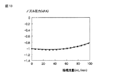
次に、インクジェット記録装置3において、液面センサS6を上げ、S9を下げて循環流量を0−100mL/分まで変化させたとき場合について、説明する。S6を上げ、同じだけS9を下げれば上流側タンクの圧力が上がり、下流側タンクの圧力が下がって循環流量は増大する。S6の高さを変えつつ同じだけS9の高さを逆方向へ移動し、循環流量を0−100mL/分まで変化させたときには、循環流量に対してノズル17近傍の圧力は図12のように変化する。即ち、循環流量が30mLよりも大きくなると、ノズル17近傍の圧力は正圧側に移動して行く。ここで、目標の循環流量が30mLより大きい場合は、hau、halの差、即ち循環開始前の上流側インクタンクと下流側インクタンクの空気層の高さの差を大きくすれば良い。例えばhau=52mm、hal=48mm、のとき、循環流量とノズル17近傍の圧力の関係は図13に示すように、より広い領域で平坦になる。
Next, in the inkjet recording apparatus 3, a case where the liquid level sensor S6 is raised and S9 is lowered to change the circulating flow rate to 0-100 mL / min will be described. If S6 is increased and S9 is decreased by the same amount, the pressure in the upstream tank increases, the pressure in the downstream tank decreases, and the circulation flow rate increases. When the height of S9 is moved in the opposite direction while changing the height of S6 and the circulating flow rate is changed to 0-100 mL / min, the pressure in the vicinity of the
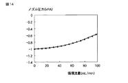
さらに、上流側タンク25と下流側タンク30の空気層の高さを変える代わりに、上流側タンク25と下流側タンク30の断面積を変えても良い。例えば、hau=50mm、hal=50mm、のとき、上流側タンク25と下流側タンク30の断面積比が1:1の場合には図14に示すような関係となり流量の増大とともにノズル17近傍の圧力は増大してしまう。そこで
上流側タンク25と下流側タンク30の断面積比を1:0.9とすれば、循環流量とノズル17近傍の圧力の関係は図15に示すような関係となり、広い領域で平坦になる。
Furthermore, instead of changing the height of the air layer of the
以上説明した例では、循環流量に対してノズル17近傍のメニスカス圧力が凹形に変化するが、さらに下流側タンク30の形状を下の方の断面積が小さいすりばち状にするなどにより、循環流量が増加した時に下流側タンク30液面のポテンシャルヘッドが大きく下がるように構成すれば、循環流量が変わってもノズル17近傍の圧力が変化しないように設定することも可能である。
In the example described above, the meniscus pressure in the vicinity of the
ここで、循環ポンプ35の作動前後でノズル17近傍の圧力が変化しないような調整方法について説明する。上記各上流側タンク25の初期状態における空気層の体積をVu、下流側タンク30の初期状態における空気層体積をVl、下流側タンク30から上流側タンク25へ移動するインクの体積をΔV、上流側タンク25の液面が初期状態から上昇した高さをΔhu、下流側タンク30の液面が初期から下降した高さを−Δhl、上流側タンク25からオリフィスプレート18の表面までの流路抵抗をRu、下流側タンク30からオリフィスプレート18の表面までの流路抵抗をRl、インク比重をρ、重力加速度をg、大気圧をPatm、上流側タンク25の上昇した空気圧をPu(ゲージ圧)、下流側タンク30の下降した空気圧をPl(ゲージ圧)、オリフィスプレート18の表面の高さに対する下流側タンク30の初期液面高さをh、ノズル17近傍の圧力をPn、とする。
Here, an adjustment method for preventing the pressure near the
初期状態では、Pn=ρghとし、循環ポンプ35を稼動させ、Δvのインクが移動したときPu=ΔV/(Vu−ΔV)Patm、PL=−ΔV/(Vl+ΔV)Patmとする。上流側タンク25の液面のポテンシャル圧力はρg(h+Δhu)となり、下流側タンク30の液面のポテンシャル圧力はρg(h+Δhl)となる。
In the initial state, Pn = ρgh, the
以下、計算を簡単にするためにRu=Rlの場合について説明すると、Pn=(1/2){Pu+ρg(h+Δhu)+PL+ρg(h+Δhl)}
=ρgh+(1/2)(Pu+Pl+ρghΔhu+ρgΔhl)
=ρgh+(1/2){ΔV(Vl−Vu)+2ΔV2}/{(Vu−ΔV)(Vl+ΔV)Patm+(ρg/2)(Δhu+Δhl)である。
循環ポンプ35の作動前後でノズル17の近傍の圧力の変化がないようにするには、
{ΔV(Vl−Vu)+2ΔV2}/{(Vu−ΔV)(Vl+ΔV)}Patm=ρg(Δhl+Δhu)−Δhl=(Patm/ρg){ΔV(Vl−Vu)+2ΔV2}/{(Vu−ΔV)(Vl+ΔV)}+Δhuとすればよい。
Hereinafter, in order to simplify the calculation, the case of Ru = Rl will be described. Pn = (1/2) {Pu + ρg (h + Δhu) + PL + ρg (h + Δhl)}
= Ρgh + (1/2) (Pu + Pl + ρghΔhu + ρgΔhl)
= Ρgh + (1/2) {ΔV (Vl−Vu) + 2ΔV 2 } / {(Vu−ΔV) (Vl + ΔV) Patm + (ρg / 2) (Δhu + Δhl).
To prevent the pressure near the
{ΔV (V1−Vu) + 2ΔV 2 } / {(Vu−ΔV) (V1 + ΔV)} Patm = ρg (Δhl + Δhu) −Δhl = (Patm / ρg) {ΔV (V1−Vu) + 2ΔV 2 } / {(Vu− [Delta] V) (Vl + [Delta] V)} + [Delta] hu.
ここで、上流側タンク25を面積Suの円柱管状であるとすれば、ΔV=SuΔhuであり、かつ、−Δhu=ΔV/Suであるので、−Δhl=Patm/ρg{ΔV(Vl−Vu)+2ΔV2}/{(Vu−ΔV)(Vl+ΔV)}+(ΔV/Su)となる(式1)。
Here, if the
Vu=Vl=Vのときは−Δhl=2(Patm/ρg)(ΔV2/V2−ΔV2)+ΔV/Suとなる(式2)。したがって、下流側タンク30の液面がΔhlを下ったとき、ΔVの体積変化となるように、下流側タンク30の断面積を式1又は式2が成立するように調整すればよい。
When Vu = Vl = V, −Δhl = 2 (Patm / ρg) (ΔV 2 / V 2 −ΔV 2 ) + ΔV / Su (Formula 2). Therefore, the cross-sectional area of the
また、空気層の高さや上流側タンク25と下流側タンク30の断面積比の代わりに、上流側流路と下流側流路の流路抵抗比を調整して流量に対するノズル17近傍の圧力変化特性を調整することもできる。例えば、hau=50mm、hal=50mm、に設定し、上流側タンク25と下流側タンク30の断面積比を1:1としたまま、上流側流路を長くするなどして流路抵抗を、Ru=4.4x10⁹ Pa・s/m3、Rl=4.0x109 Pa・s/m3とすれば、循環流量とノズル17近傍の圧力は図16に示すような関係となり、図14よりも広い領域で平坦になる。
Further, instead of the height of the air layer or the cross-sectional area ratio between the
本実施形態においても上述した第1実施形態にかかるインクジェット記録装置1と同様の効果が得られる。さらに、下流側タンクを密閉して下流側タンクの圧力を下げるだけでなく上流側タンクも密閉可能として上流側タンクの圧力を上げることができるので、各タンク25,30,50やインクジェットヘッド11の配置の自由度を向上することが可能となる。
Also in this embodiment, the same effect as the ink
なお、本発明は上記各実施形態に限定されるものではなく、本発明を実施するにあたり、各構成部材の具体的な形状など、本発明の構成要素を発明の要旨を逸脱しない範囲で種々に変更して実施できることは言うまでもない。例えば、上記各実施形態では循環ポンプ35は液面センサを検知して制御したが、一定流量で動作させても良い。また、上記各実施形態ではインクの補給は、液面センサ3を検知して制御したが、下流側タンク30の重量が一定になるように制御しても良い。
It should be noted that the present invention is not limited to the above-described embodiments, and various elements of the present invention, such as specific shapes of the respective constituent members, may be used in carrying out the present invention without departing from the spirit of the invention. Needless to say, it can be implemented with changes. For example, in each of the embodiments described above, the
供給タンク47からのインク補給は供給ポンプ38による構成でも、供給タンク47の液面高さと下流側タンク30の負圧とユーザータンクから下流側タンク30の流路抵抗とで決まる自然補給流量を利用してバルブで補給を制御する構成でもどちらでもよい。
Ink supply from the
上記各実施形態では供給ポンプ38は液面センサを検知して制御したが、供給ポンプ38を正逆転可能とし、かつ圧力計31と圧力計32の値をRuとRlで分圧した値を計算し、これが0より小さいとき供給ポンプを正転してインクを補給し、0より大きいときは逆転してインクを供給タンク47に戻す制御を行うことで計算値が0になるように制御しても良い。このように制御するとhau,halが変わってもノズル近傍の圧力に対するの影響はポテンシャル圧力差分だけしか生じないので、hau,halをあまり厳密に合わせる必要が無いという利点がある。
In each of the above embodiments, the supply pump 38 is controlled by detecting the liquid level sensor. However, the supply pump 38 can be rotated forward and backward, and the value obtained by dividing the
このように供給ポンプ38が正逆転可能であれば上流側タンク25及び下流側タンク30は必ずしもヘッドより下にある必要は無く、ヘッドよりも高いところに位置してバルブを閉じて供給ポンプを逆転させて負圧を生成しても良い。例えば、上流側タンク25と下流側タンク30の液面をノズルより上30mmの場所に設置する。hau=hal=50mmとする。この時バルブ1とバルブ2は開いておくので、ノズルからインクが滴下する恐れがあるが、実施例2で説明した方法によってこれを防いでおく。次いでバルブ1、バルブ2を閉じ、圧力計1と圧力計2の読みをRuとRlで分圧した値、即ちこの実施例ではRu=Rlなので圧力計31と圧力計32の読みの平均値Paveに従って、Paveが−1kPaより正圧側の時は供給ポンプを逆転させてインクを供給タンクに戻し、Paveが−1kPaより負圧側の時は供給ポンプを正転させてインクを補給すれば、ノズル圧力は−1kPaになる。この時上流側タンク25、下流側タンク30の液面は初期より低下している。次いで循環ポンプを30.4mL/minで駆動すると、上流側タンク25の液面は上昇し下流側タンク30の液面は低下する。この状態での上流側タンク25の液面と下流側タンク30の液面はバルブを閉じた時点、すなわちノズルより上30mmの位置を基準として、Δhu=0.38mm、Δhl=−1.67mmである。この液面高さ変化はノズル近傍の圧力に対する影響としては無視できる程度に小さい。この間もPave=−1kPaとなるように供給ポンプを適宜正転、逆転制御しておけば、ノズル近傍の圧力は循環起動前から循環中に亘りほぼ−1kPaに維持できる。
Thus, if the supply pump 38 can be rotated forward and backward, the
使用しない冗長なセンサー類は省略することもできるが、省略せずに異常検出のために用いても良い。液面センサとポンプ流量の関係から異常を知ることができる。例えば、定流量で循環停止状態から循環ポンプを駆動した時は、上流側タンク25の液面センサの位置を検知するまでの時間を測定してもよい。時間が所定範囲よりも長ければ、循環ポンプから上流側タンク25までに異常があるか、ポンプの動作に異常がある。又圧力計は以下のように異常検出に利用できる。例えば上流ポートの接続が外れていれば、循環ポンプが作動しているにもかかわらず圧力計31の圧力が上がらないので、液面センサで判断するよりも早く異常を知ることができる。さらに、液面センサと圧力センサの読み値が予測と異なる場合にどこかに異常があると判断することもできる。循環ポンプ35を起動してから液面センサが所定位置に達する時間を計測して、所定の範囲に無い場合に異常を判断することもできる。例えば循環停止状態から循環ポンプを起動し、所定の時間内に上流側タンク25の液面が液面センサに到達しなければ、循環ポンプが送液できていないか、又は上流側流路から先にインク漏れがある。逆に所定の時間より短時間で液面センサに到達した場合は上流側タンク25の気密がとれていないと判断可能である。循環中の液面高さ変動や圧力変動が所定の範囲に収まっているかどうかで異常の有無を検知しても良い。
Redundant sensors that are not used can be omitted, but may be used for abnormality detection without being omitted. Abnormality can be known from the relationship between the liquid level sensor and the pump flow rate. For example, when the circulation pump is driven from the circulation stop state at a constant flow rate, the time until the position of the liquid level sensor in the
上記各実施形態において、インクジェットヘッド11〜16の構成として図2に示すように、インクの圧力室19を介してインク20を循環させつつ吐出させる構成を例示したがこれに限られるものではない。例えば、図17で示すインクジェットヘッド50のように、インク貯留部52にインクを循環供給する方法も適用可能である。このインクジェットヘッド50は、複数のノズル51と、このノズル51に対応して形成された発熱素子51a、インク貯留部52、このインク貯留部52の上流側及び下流側に連通する流路53,54、等を備えている。この流路53、54が、それぞれ上記各実施形態のインク供給機構10における第4導管44、第5導管45に連通されることで、上記各実施形態と同様に機能するとともに上記各実施形態と同様の効果を得られる。この形態ではインク貯留部52から離間して、スリット52aを介して、圧力室52bとメニスカスが形成されるノズル51を備えており、インク貯留部52はインク循環部分とスリット52aを介した圧力室52b、ノズル51との分岐点であると考えることができる。このようなヘッドにインクを循環させた時、インク貯留部52とノズル51の表面の高さがほとんど違わないとすれば、非吐出時にはこの分岐点とノズルのメニスカス圧力はほぼ等しい。したがって、インク貯留部52のインク圧力をノズルのメニスカス圧力と考えて実施すればよい。又、吐出時は吐出流量に分岐点からノズルまでの流路抵抗を掛けた圧力だけノズルのメニスカス圧力が下がると考えればよい。
In each of the above-described embodiments, as shown in FIG. 2, the configuration of the inkjet heads 11 to 16 exemplifies the configuration in which the
さらには、このインクジェット装置に使用されるインクジェットヘッドは、循環経路の途中からフィルタを介してアクチュエータ、ノズルへ分岐しているタイプでも良い。この場合も、フィルタとノズル51の表面の高さがほとんど違わないとすれば、非吐出状態ではノズルの圧力はフィルタ1次側が循環経路と接する部分の圧力と同一と考えることが出来る。又吐出時は吐出流量にフィルタ1次側からノズルまでの流路抵抗を掛けた圧力だけノズルの圧力が下がると考えればよい。アクチュエータ22として、上記実施形態に示すもの以外にも、例えば、ピエゾ式、ピエゾシェアモード式、サーマルインクジェット式等も適用可能である。 Furthermore, the ink jet head used in this ink jet apparatus may be of a type that branches from the middle of the circulation path to an actuator and a nozzle via a filter. Also in this case, if the heights of the surface of the filter and the nozzle 51 are almost the same, the pressure of the nozzle can be considered to be the same as the pressure at the portion where the primary side of the filter is in contact with the circulation path in the non-ejection state. Further, it can be considered that the pressure of the nozzle is reduced by a pressure obtained by multiplying the discharge flow rate by the flow path resistance from the primary side of the filter to the nozzle during discharge. For example, a piezo type, a piezo shear mode type, a thermal ink jet type, or the like can be applied as the actuator 22 other than the one shown in the above embodiment.
また、オリフィスプレート表面に複数のノズル開口があって各々の高さが異なる場合には、高さの違いに起因するノズル近傍の圧力の違いが適正なノズル近傍の圧力の範囲を超えない限りにおいて、各ノズルの高さの平均をオリフィスプレート表面の高さと考えれば良い。この時ヘッド内のインク循環流の方向を高さの低いノズルに近い方から高さの高いノズルに近い方に向かってとれば、高さの違いに起因するノズル近傍の圧力の違いを減らすことができるので、そのようにしても良い。 Also, if there are multiple nozzle openings on the orifice plate surface and the heights are different, as long as the pressure difference near the nozzle due to the difference in height does not exceed the pressure range near the proper nozzle The average of the heights of the nozzles may be considered as the height of the orifice plate surface. At this time, if the direction of the ink circulation flow in the head is from the side closer to the nozzle with a lower height to the side closer to the nozzle with a higher height, the difference in pressure in the vicinity of the nozzle due to the difference in height is reduced. You can do that.
また、上記第1実施形態では、循環ポンプ35を液面センサに従って作動させ下流側タンク30空気層のゲージ圧PLを得たが、液面センサを設ける代わりに下流側タンク30空気層のゲージ圧を測定する圧力センサを設け、測定結果がPL(負値)より大きい(絶対値が小さい)間だけ循環ポンプを作動させて直接圧力PLを維持する制御を行う方法もある。
In the first embodiment, the
また、液面センサ又は圧力センサの出力を閾値判断してポンプをON/OFF制御する代わりに液面センサ又は圧力センサの出力をアナログ出力とし、かつ循環ポンプはON/OFF制御ではなく前記のアナログ出力値に従って流量を変化させる制御を行い、液面センサ又は圧力センサの出力が所定値の時に循環ポンプが目標流量に一致するようにしておけば、より脈動の少ないスムースな制御を実現できる。 Also, instead of judging the threshold of the output of the liquid level sensor or pressure sensor and controlling the pump ON / OFF, the output of the liquid level sensor or pressure sensor is set to an analog output, and the circulation pump is not the ON / OFF control but the analog If the flow rate is controlled according to the output value and the output of the liquid level sensor or the pressure sensor is a predetermined value so that the circulating pump matches the target flow rate, smooth control with less pulsation can be realized.
さらに、各実施形態の構成を別の実施形態の構成と組み合わせても良い。すなわち、第1実施形態や第3実施形態においてインクジェットヘッドを複数設けてもよく、第1実施形態や第2実施形態で供給ポンプ38を用いて供給タンク50をヘッドよりも下方に配置しても良い。この他、各構成部材の方向、材質、数、具体的な形状など、本発明の構成要素を発明の要旨を逸脱しない範囲で種々に変更して実施できる。
Furthermore, the configuration of each embodiment may be combined with the configuration of another embodiment. That is, a plurality of inkjet heads may be provided in the first embodiment or the third embodiment, and the
1,2,3…インクジェット記録装置、V1〜V10…バルブ、
S1〜S9…液面センサ、10…インク供給機構、11〜16…インクジェットヘッド
17…ノズル、18…オリフィスプレート、19…圧力室、20…インク、
21…メニスカス、25…上流側タンク、28…通気パイプ、29…インク補給パイプ、
30…下流側タンク、35…循環ポンプ、37…制御部、38…供給ポンプ、
38…ポンプ、40…循環路、41〜46…導管、47…供給タンク。
1, 2, 3 ... Inkjet recording device, V1-V10 ... Valve,
S1 to S9 ... Liquid level sensor, 10 ... Ink supply mechanism, 11-16 ...
21 ... meniscus, 25 ... upstream tank, 28 ... vent pipe, 29 ... ink supply pipe,
30 ... downstream tank, 35 ... circulation pump, 37 ... control unit, 38 ... supply pump,
38 ... pump, 40 ... circulation path, 41-46 ... conduit, 47 ... supply tank.
Claims (1)
前記上流ポートを介して前記インクジェットヘッドと連通し、インクを貯留する上流側タンクと、
前記下流ポートを介して前記インクジェットヘッドと連通し、インクを貯留する下流側タンクと、
前記下流側タンクから上流側タンクへインクを戻す循環ポンプと、を連通して構成される循環系を備え、
少なくとも前記下流側タンクの空気を大気圧に開閉するバルブを持ち、
前記上流側タンク及び前記下流側タンクのうち、少なくともいずれか一方の内部のイン
クの液面の高さを検知する液面検出器を備え、
前記バルブ及び前記循環ポンプに接続されるとともに、前記循環ポンプ及びバルブの開閉動作を制御し、前記バルブを閉じ前記循環ポンプを駆動することで、前記下流側タンクを負圧にし、帰還流路を介して前記下流側タンクから前記上流側タンクへインクを戻してインクを循環させる制御装置を備え、
前記制御装置は、前記液面検出器で検出された液面高さに応じて前記ポンプを制御する、ことを特徴とするインク供給機構。 An inkjet head having a nozzle, a pressure chamber facing the nozzle, an upstream port communicating with the pressure chamber, and a downstream port;
An upstream tank that communicates with the inkjet head via the upstream port and stores ink;
A downstream tank that communicates with the inkjet head via the downstream port and stores ink;
A circulation system configured to communicate with a circulation pump that returns ink from the downstream tank to the upstream tank;
At least a valve that opens and closes the air in the downstream tank to atmospheric pressure,
Inner of at least one of the upstream tank and the downstream tank
Equipped with a liquid level detector that detects the liquid level of the
It is connected to the valve and the circulation pump, controls the opening and closing operation of the circulation pump and the valve, closes the valve and drives the circulation pump, thereby bringing the downstream tank to a negative pressure and a return flow path. via a control device to circulate the ink back to the ink to the upstream tank from the downstream side tank,
The ink supply mechanism , wherein the control device controls the pump according to a liquid level detected by the liquid level detector .
Applications Claiming Priority (2)
| Application Number | Priority Date | Filing Date | Title |
|---|---|---|---|
| US11/617,256 | 2006-12-28 | ||
| US11/617,256 US7845784B2 (en) | 2006-12-28 | 2006-12-28 | Ink supplying mechanism and ink supplying method |
Related Child Applications (1)
| Application Number | Title | Priority Date | Filing Date |
|---|---|---|---|
| JP2012028672A Division JP5122691B2 (en) | 2006-12-28 | 2012-02-13 | Ink jet recording apparatus, ink supply mechanism, and ink supply method |
Publications (3)
| Publication Number | Publication Date |
|---|---|
| JP2008162262A JP2008162262A (en) | 2008-07-17 |
| JP2008162262A5 JP2008162262A5 (en) | 2010-10-07 |
| JP5085249B2 true JP5085249B2 (en) | 2012-11-28 |
Family
ID=39583280
Family Applications (3)
| Application Number | Title | Priority Date | Filing Date |
|---|---|---|---|
| JP2007244368A Active JP5085249B2 (en) | 2006-12-28 | 2007-09-20 | Ink supply mechanism |
| JP2012028672A Active JP5122691B2 (en) | 2006-12-28 | 2012-02-13 | Ink jet recording apparatus, ink supply mechanism, and ink supply method |
| JP2012231661A Pending JP2013010366A (en) | 2006-12-28 | 2012-10-19 | Inkjet recording device, ink feeding mechanism, and ink feeding method |
Family Applications After (2)
| Application Number | Title | Priority Date | Filing Date |
|---|---|---|---|
| JP2012028672A Active JP5122691B2 (en) | 2006-12-28 | 2012-02-13 | Ink jet recording apparatus, ink supply mechanism, and ink supply method |
| JP2012231661A Pending JP2013010366A (en) | 2006-12-28 | 2012-10-19 | Inkjet recording device, ink feeding mechanism, and ink feeding method |
Country Status (2)
| Country | Link |
|---|---|
| US (2) | US7845784B2 (en) |
| JP (3) | JP5085249B2 (en) |
Families Citing this family (84)
| Publication number | Priority date | Publication date | Assignee | Title |
|---|---|---|---|---|
| US7597434B2 (en) * | 2006-04-27 | 2009-10-06 | Toshiba Tec Kabushiki Kaisha | Ink-jet apparatus and method of the same |
| EP1932671A1 (en) * | 2006-12-11 | 2008-06-18 | Agfa Graphics N.V. | Shuttle mounted pressure control device for injet printer |
| US7845784B2 (en) * | 2006-12-28 | 2010-12-07 | Kabushiki Kaisha Toshiba | Ink supplying mechanism and ink supplying method |
| JP4839274B2 (en) * | 2007-07-13 | 2011-12-21 | 東芝テック株式会社 | Inkjet head, inkjet recording apparatus |
| ITRE20080022A1 (en) * | 2008-02-19 | 2009-08-20 | Vincenzo Palumbo | INK FEEDING SYSTEM FOR PRINTERS |
| JP5154258B2 (en) * | 2008-02-21 | 2013-02-27 | 理想科学工業株式会社 | Inkjet printer |
| JP5190297B2 (en) * | 2008-05-15 | 2013-04-24 | 理想科学工業株式会社 | Inkjet printer |
| JP5084609B2 (en) * | 2008-05-27 | 2012-11-28 | 大日本スクリーン製造株式会社 | Head unit and printing apparatus |
| JP4535181B2 (en) * | 2008-08-26 | 2010-09-01 | ブラザー工業株式会社 | Control method for liquid ejection device and liquid ejection device |
| JP5292037B2 (en) * | 2008-09-25 | 2013-09-18 | 理想科学工業株式会社 | Inkjet recording device |
| JP5209431B2 (en) * | 2008-09-30 | 2013-06-12 | 富士フイルム株式会社 | Inkjet recording device |
| JP2010105169A (en) * | 2008-10-28 | 2010-05-13 | Olympus Corp | Ink filling method |
| JP2010125701A (en) * | 2008-11-27 | 2010-06-10 | Olympus Corp | Inkjet printer |
| JP5350820B2 (en) * | 2009-01-30 | 2013-11-27 | 理想科学工業株式会社 | Inkjet printer and ink circulation method |
| JP4869373B2 (en) * | 2009-03-25 | 2012-02-08 | 株式会社東芝 | Liquid circulation unit, liquid circulation device, droplet spray coating device, and method for forming coated body |
| JP5245993B2 (en) * | 2009-04-01 | 2013-07-24 | 株式会社リコー | Inkjet recording device |
| US8172364B2 (en) * | 2009-06-30 | 2012-05-08 | Eastman Kodak Company | Flow through dispenser including improved guide structure |
| US8439493B2 (en) | 2009-07-31 | 2013-05-14 | Zamtec Ltd | Wide format printer with printheads supplied by multiple ink conduits connected by a bypass line |
| JP5741786B2 (en) * | 2009-11-27 | 2015-07-01 | セイコーエプソン株式会社 | Liquid ejector |
| DE102009058219A1 (en) * | 2009-12-15 | 2011-06-16 | Till, Volker, Dipl.-Ing. | Plant for printing on containers |
| CN102145586B (en) | 2010-02-05 | 2014-01-15 | 精工爱普生株式会社 | Fluid ejecting apparatus and cleaning method |
| JP5555505B2 (en) * | 2010-02-17 | 2014-07-23 | 理想科学工業株式会社 | Inkjet printer |
| JP5537988B2 (en) * | 2010-02-23 | 2014-07-02 | 富士フイルム株式会社 | Abnormality determination apparatus and abnormality determination method for liquid supply system |
| JP5361764B2 (en) * | 2010-02-25 | 2013-12-04 | 理想科学工業株式会社 | Inkjet printer and abnormality detection method thereof |
| JP5525885B2 (en) * | 2010-03-26 | 2014-06-18 | 富士フイルム株式会社 | Liquid applying apparatus, image forming apparatus, and pump and filter determination method |
| JP5468956B2 (en) * | 2010-03-29 | 2014-04-09 | 理想科学工業株式会社 | Inkjet printer |
| US20110279562A1 (en) * | 2010-05-17 | 2011-11-17 | Silverbrook Research Pty Ltd | System for distributing fluid and gas within printer |
| TW201210843A (en) | 2010-05-17 | 2012-03-16 | Silverbrook Res Pty Ltd | Printing system having printhead bypass |
| JP2011257976A (en) * | 2010-06-09 | 2011-12-22 | Kawamura Electric Inc | Cooling system for server rack |
| JP2012016904A (en) * | 2010-07-08 | 2012-01-26 | Fuji Xerox Co Ltd | Liquid supply controller, liquid droplet discharge device and liquid supply control program |
| JP5569222B2 (en) | 2010-07-30 | 2014-08-13 | ブラザー工業株式会社 | Liquid ejection device |
| US20120033019A1 (en) | 2010-08-09 | 2012-02-09 | Toshiba Tec Kabushiki Kaisha | Inkjet recording apparatus and inkjet recording method |
| US8876243B2 (en) * | 2010-09-13 | 2014-11-04 | Toshiba Tec Kabushiki Kaisha | Inkjet recording device and inkjet recording method |
| JP5400736B2 (en) * | 2010-09-14 | 2014-01-29 | 東芝テック株式会社 | Inkjet device |
| JP2012152931A (en) * | 2011-01-24 | 2012-08-16 | Riso Kagaku Corp | Inkjet printing apparatus |
| JP5723610B2 (en) * | 2011-01-26 | 2015-05-27 | 理想科学工業株式会社 | Inkjet recording device |
| JP5776226B2 (en) | 2011-03-04 | 2015-09-09 | セイコーエプソン株式会社 | Liquid ejecting apparatus and control method thereof |
| JP5776227B2 (en) * | 2011-03-04 | 2015-09-09 | セイコーエプソン株式会社 | Liquid ejecting apparatus and control method thereof |
| JP2012223971A (en) * | 2011-04-19 | 2012-11-15 | Riso Kagaku Corp | Inkjet printer |
| ITMI20111034A1 (en) * | 2011-06-08 | 2012-12-09 | Telecom Italia Spa | DEVICE FOR PRINTING INTO JET OF A SURFACE |
| JP6124790B2 (en) * | 2011-08-24 | 2017-05-10 | コニカミノルタ株式会社 | Inkjet recording device |
| JP2013071038A (en) * | 2011-09-27 | 2013-04-22 | Dainippon Screen Mfg Co Ltd | Degassing apparatus on liquid feed line and inkjet printing apparatus having the same |
| JP5439511B2 (en) * | 2012-01-23 | 2014-03-12 | 東芝テック株式会社 | Ink supply device |
| JP5659179B2 (en) * | 2012-03-16 | 2015-01-28 | 東芝テック株式会社 | Image forming apparatus |
| JP5832975B2 (en) | 2012-09-07 | 2015-12-16 | 株式会社東芝 | Ink jet recording apparatus and recording method |
| CN105209261B (en) * | 2013-05-20 | 2017-03-22 | 柯尼卡美能达株式会社 | Inkjet printing device and print head maintenance method |
| KR101397307B1 (en) | 2013-07-22 | 2014-05-23 | 부경대학교 산학협력단 | Device and method for precise meniscus pressure control of printer |
| WO2015016119A1 (en) * | 2013-07-29 | 2015-02-05 | 京セラドキュメントソリューションズ株式会社 | Liquid supply mechanism and printing device |
| CN104417069B (en) * | 2013-08-26 | 2016-06-22 | 东芝泰格有限公司 | The circulation controlling means of image processing system and ink |
| JP5742928B2 (en) * | 2013-12-26 | 2015-07-01 | セイコーエプソン株式会社 | Liquid ejector |
| JP6280742B2 (en) | 2013-12-27 | 2018-02-14 | 東芝テック株式会社 | Liquid circulation device, liquid discharge recording device, and liquid circulation method |
| JP6590797B2 (en) * | 2014-05-16 | 2019-10-16 | 株式会社ミマキエンジニアリング | Damper, ink circulation method and ink circulation mechanism |
| US10124617B2 (en) * | 2014-06-16 | 2018-11-13 | Ricoh Company, Ltd. | Liquid stirrer and image forming apparatus including same |
| JP6322499B2 (en) * | 2014-07-02 | 2018-05-09 | 理想科学工業株式会社 | Inkjet printing device |
| DE102014110520A1 (en) * | 2014-07-25 | 2016-01-28 | Krones Ag | Direct printing machine with ink supply system |
| JP6291378B2 (en) | 2014-07-30 | 2018-03-14 | 理想科学工業株式会社 | Inkjet printing device |
| WO2016024973A1 (en) | 2014-08-14 | 2016-02-18 | Hewlett-Packard Development Company, L.P. | Printer fluid circulation system including an air isolation chamber and a printer fluid pressure control valve |
| JP6393553B2 (en) * | 2014-08-21 | 2018-09-19 | 理想科学工業株式会社 | Inkjet printing device |
| JP6400397B2 (en) * | 2014-09-08 | 2018-10-03 | 芝浦メカトロニクス株式会社 | Coating liquid supply apparatus, coating apparatus and coating liquid supply method |
| JP6322101B2 (en) | 2014-09-16 | 2018-05-09 | 理想科学工業株式会社 | Inkjet printing device |
| JP6363446B2 (en) | 2014-09-22 | 2018-07-25 | 理想科学工業株式会社 | Inkjet printing device |
| JP6397294B2 (en) * | 2014-09-29 | 2018-09-26 | 理想科学工業株式会社 | Inkjet printing device |
| JP6435149B2 (en) | 2014-09-29 | 2018-12-05 | 理想科学工業株式会社 | Inkjet printing device |
| JP6400413B2 (en) | 2014-09-29 | 2018-10-03 | ローランドディー.ジー.株式会社 | Ink supply system, ink jet printer, ink filling method, and method of using ink supply system |
| JP6394347B2 (en) * | 2014-12-11 | 2018-09-26 | セイコーエプソン株式会社 | Liquid ejector |
| JP6047548B2 (en) * | 2014-12-22 | 2016-12-21 | 株式会社東芝 | Inkjet recording head |
| JP6555952B2 (en) * | 2015-07-10 | 2019-08-07 | 住友重機械工業株式会社 | Ink ejection apparatus and ink ejection method |
| JP6594194B2 (en) * | 2015-12-24 | 2019-10-23 | 株式会社Screenホールディングス | Inkjet printer and liquid feeding state confirmation method |
| EP3437884B1 (en) * | 2016-03-28 | 2021-10-13 | Konica Minolta, Inc. | Inkjet recording device |
| JP6181830B2 (en) * | 2016-09-27 | 2017-08-16 | 株式会社東芝 | Method for manufacturing ink jet recording head |
| JP2017019292A (en) * | 2016-10-20 | 2017-01-26 | 東芝テック株式会社 | Liquid discharge device and liquid transport method |
| JP6971568B2 (en) * | 2016-12-21 | 2021-11-24 | 東芝テック株式会社 | Liquid circulation module and liquid discharge device |
| KR20190059940A (en) * | 2017-01-17 | 2019-05-31 | 니혼 덴산 가부시키가이샤 | Application device and bubble removal method |
| JP2018154068A (en) * | 2017-03-21 | 2018-10-04 | 株式会社リコー | Liquide circulation device and device for discharging liquid |
| JP6963914B2 (en) * | 2017-05-31 | 2021-11-10 | シーメット株式会社 | Liquid material supply equipment and 3D modeling equipment |
| JP6557289B2 (en) * | 2017-06-21 | 2019-08-07 | 東芝テック株式会社 | Liquid circulation device and liquid discharge recording device |
| JP7027709B2 (en) * | 2017-07-04 | 2022-03-02 | 株式会社リコー | Device that discharges liquid |
| JP7052521B2 (en) * | 2018-04-20 | 2022-04-12 | 京セラドキュメントソリューションズ株式会社 | Ink supply device, inkjet recording device and communication failure determination method |
| GB2584617B (en) * | 2019-05-21 | 2021-10-27 | Xaar Technology Ltd | Piezoelectric droplet deposition apparatus optimised for high viscosity fluids, and methods and control system therefor |
| JP6833301B2 (en) * | 2019-06-17 | 2021-02-24 | 住友重機械工業株式会社 | Ink supply device |
| JP7432114B2 (en) | 2020-03-31 | 2024-02-16 | ブラザー工業株式会社 | inkjet recording device |
| JP7517933B2 (en) | 2020-09-28 | 2024-07-17 | 理想科学工業株式会社 | Inkjet Printing Device |
| JP2022150983A (en) * | 2021-03-26 | 2022-10-07 | ブラザー工業株式会社 | Liquid ejection device |
| WO2024075194A1 (en) * | 2022-10-05 | 2024-04-11 | 株式会社日立産機システム | Inkjet recording device, and inkjet recording device abnormality diagnosis method |
Family Cites Families (27)
| Publication number | Priority date | Publication date | Assignee | Title |
|---|---|---|---|---|
| DE3446998A1 (en) * | 1983-12-26 | 1985-07-04 | Canon K.K., Tokio/Tokyo | INK-JET RECORDING DEVICE |
| EP0448967B1 (en) * | 1990-02-26 | 1996-07-03 | Canon Kabushiki Kaisha | Ink jet recording apparatus and method for recovering recording head |
| JPH05330073A (en) * | 1992-06-03 | 1993-12-14 | Canon Inc | Method for restoring emission of recording head of ink jet recording apparatus |
| JP3419220B2 (en) | 1996-10-15 | 2003-06-23 | セイコーエプソン株式会社 | Ink jet recording device |
| JP3380707B2 (en) * | 1997-05-16 | 2003-02-24 | キヤノンアプテックス株式会社 | Ink jet recording device |
| JP3363760B2 (en) * | 1997-11-14 | 2003-01-08 | キヤノン株式会社 | Ink supply device and printing device |
| JP3846083B2 (en) * | 1998-02-06 | 2006-11-15 | ブラザー工業株式会社 | Inkjet recording device |
| GB9828476D0 (en) | 1998-12-24 | 1999-02-17 | Xaar Technology Ltd | Apparatus for depositing droplets of fluid |
| JP2000289222A (en) | 1999-04-12 | 2000-10-17 | Canon Inc | Liquid ejection recording apparatus, liquid supply method, liquid removing method, and liquid replacing method for the liquid ejection recording apparatus |
| EP1361066B1 (en) * | 2000-06-29 | 2005-09-14 | Agfa-Gevaert N.V. | A fluid supply system including a degassing unit |
| US6371607B2 (en) * | 2000-06-29 | 2002-04-16 | Agfa-Gevaert | Ink jet printer and an ink supply system therefore |
| US6742882B2 (en) * | 2001-06-26 | 2004-06-01 | Brother Kogyo Kabushiki Kaisha | Air purge device for ink jet recording apparatus |
| GB0121909D0 (en) | 2001-09-11 | 2001-10-31 | Xaar Technology Ltd | Droplet deposition apparatus |
| JP4064739B2 (en) | 2002-06-24 | 2008-03-19 | 東芝テック株式会社 | Inkjet head maintenance method and maintenance apparatus |
| JP2005041191A (en) * | 2003-07-25 | 2005-02-17 | Canon Finetech Inc | Ink jet recorder and recovery method |
| JP2005144954A (en) * | 2003-11-18 | 2005-06-09 | Toshiba Tec Corp | Ink jet unit |
| JP2005161633A (en) | 2003-12-02 | 2005-06-23 | Canon Inc | Inkjet recording head and inkjet recording device |
| JP4384067B2 (en) * | 2004-03-23 | 2009-12-16 | キヤノン株式会社 | Liquid ejecting apparatus and liquid processing method |
| AU2005283947A1 (en) | 2004-09-18 | 2006-03-23 | Xaar Technology Limited | Fluid supply method and apparatus |
| JP2006150745A (en) * | 2004-11-29 | 2006-06-15 | Canon Inc | Inkjet recording device |
| JP2006159722A (en) * | 2004-12-09 | 2006-06-22 | Canon Inc | Ink jet recorder |
| US7874656B2 (en) * | 2004-12-10 | 2011-01-25 | Canon Finetech Inc. | Ink-feeding device and pressure-generating method |
| EP1846245B1 (en) | 2004-12-17 | 2009-04-29 | Agfa Graphics Nv | System and method for supplying an ink to a reciprocating printhead in an inkjet printing apparatus |
| JP2006175651A (en) | 2004-12-21 | 2006-07-06 | Canon Inc | Inkjet recording device |
| JP2006224435A (en) * | 2005-02-17 | 2006-08-31 | Canon Inc | Inkjet recording device |
| US7597434B2 (en) * | 2006-04-27 | 2009-10-06 | Toshiba Tec Kabushiki Kaisha | Ink-jet apparatus and method of the same |
| US7845784B2 (en) * | 2006-12-28 | 2010-12-07 | Kabushiki Kaisha Toshiba | Ink supplying mechanism and ink supplying method |
-
2006
- 2006-12-28 US US11/617,256 patent/US7845784B2/en active Active
-
2007
- 2007-09-20 JP JP2007244368A patent/JP5085249B2/en active Active
-
2010
- 2010-11-23 US US12/952,494 patent/US8109613B2/en active Active
-
2012
- 2012-02-13 JP JP2012028672A patent/JP5122691B2/en active Active
- 2012-10-19 JP JP2012231661A patent/JP2013010366A/en active Pending
Also Published As
| Publication number | Publication date |
|---|---|
| US20110063381A1 (en) | 2011-03-17 |
| JP5122691B2 (en) | 2013-01-16 |
| US7845784B2 (en) | 2010-12-07 |
| JP2013010366A (en) | 2013-01-17 |
| JP2008162262A (en) | 2008-07-17 |
| US8109613B2 (en) | 2012-02-07 |
| US20080158307A1 (en) | 2008-07-03 |
| JP2012091527A (en) | 2012-05-17 |
Similar Documents
| Publication | Publication Date | Title |
|---|---|---|
| JP5085249B2 (en) | Ink supply mechanism | |
| JP5031545B2 (en) | Inkjet recording apparatus, ink supply mechanism, and inkjet recording method | |
| JP5728148B2 (en) | Ink jet apparatus and control method thereof | |
| JP5599077B2 (en) | Inkjet printing device | |
| US20100194798A1 (en) | Inkjet printer and ink circulation method thereof | |
| US9827777B2 (en) | Liquid management system | |
| WO2008071609A1 (en) | Shuttle mounted pressure control device for injet printer | |
| JP2010012637A (en) | Image formation system | |
| US10611171B2 (en) | Device and method for ink supply in digital printing | |
| JP5363826B2 (en) | Coating device | |
| JP7363339B2 (en) | Liquid injection equipment, maintenance method for liquid injection equipment | |
| JP7318158B2 (en) | Ink supply system for print module and method for supplying ink | |
| JP2016120613A (en) | Liquid supply system and method for driving liquid supply system | |
| JP2022163205A (en) | Liquid jet device and control method of liquid jet device | |
| JP2006247450A (en) | Liquid delivery apparatus and patterning apparatus | |
| JP2015089654A (en) | Ink jet printer | |
| JP2009292097A (en) | Inkjet recording device | |
| JP2015229308A (en) | Nozzle cleaning method in inkjet method, and inkjet device |
Legal Events
| Date | Code | Title | Description |
|---|---|---|---|
| A521 | Request for written amendment filed |
Free format text: JAPANESE INTERMEDIATE CODE: A523 Effective date: 20100310 |
|
| A621 | Written request for application examination |
Free format text: JAPANESE INTERMEDIATE CODE: A621 Effective date: 20100310 |
|
| A521 | Request for written amendment filed |
Free format text: JAPANESE INTERMEDIATE CODE: A523 Effective date: 20100825 |
|
| A131 | Notification of reasons for refusal |
Free format text: JAPANESE INTERMEDIATE CODE: A131 Effective date: 20111213 |
|
| A977 | Report on retrieval |
Free format text: JAPANESE INTERMEDIATE CODE: A971007 Effective date: 20111214 |
|
| A521 | Request for written amendment filed |
Free format text: JAPANESE INTERMEDIATE CODE: A523 Effective date: 20120213 |
|
| RD04 | Notification of resignation of power of attorney |
Free format text: JAPANESE INTERMEDIATE CODE: A7424 Effective date: 20120529 |
|
| TRDD | Decision of grant or rejection written | ||
| A01 | Written decision to grant a patent or to grant a registration (utility model) |
Free format text: JAPANESE INTERMEDIATE CODE: A01 Effective date: 20120807 |
|
| A01 | Written decision to grant a patent or to grant a registration (utility model) |
Free format text: JAPANESE INTERMEDIATE CODE: A01 |
|
| A61 | First payment of annual fees (during grant procedure) |
Free format text: JAPANESE INTERMEDIATE CODE: A61 Effective date: 20120905 |
|
| R150 | Certificate of patent or registration of utility model |
Ref document number: 5085249 Country of ref document: JP Free format text: JAPANESE INTERMEDIATE CODE: R150 Free format text: JAPANESE INTERMEDIATE CODE: R150 |
|
| FPAY | Renewal fee payment (event date is renewal date of database) |
Free format text: PAYMENT UNTIL: 20150914 Year of fee payment: 3 |
|
| S111 | Request for change of ownership or part of ownership |
Free format text: JAPANESE INTERMEDIATE CODE: R313111 |
|
| S531 | Written request for registration of change of domicile |
Free format text: JAPANESE INTERMEDIATE CODE: R313531 |
|
| R350 | Written notification of registration of transfer |
Free format text: JAPANESE INTERMEDIATE CODE: R350 |