JP5728148B2 - Ink jet apparatus and control method thereof - Google Patents
Ink jet apparatus and control method thereof Download PDFInfo
- Publication number
- JP5728148B2 JP5728148B2 JP2007105265A JP2007105265A JP5728148B2 JP 5728148 B2 JP5728148 B2 JP 5728148B2 JP 2007105265 A JP2007105265 A JP 2007105265A JP 2007105265 A JP2007105265 A JP 2007105265A JP 5728148 B2 JP5728148 B2 JP 5728148B2
- Authority
- JP
- Japan
- Prior art keywords
- ink
- pressure
- nozzle
- flow path
- tank
- Prior art date
- Legal status (The legal status is an assumption and is not a legal conclusion. Google has not performed a legal analysis and makes no representation as to the accuracy of the status listed.)
- Active
Links
Images


Landscapes
- Ink Jet (AREA)
Description
この発明は、インクジェットヘッドを通してインクを循環させ、そのインクジェットヘッドのノズルからインクを吐出するインクジェット装置およびその制御方法に関する。 The present invention relates to an ink jet apparatus that circulates ink through an ink jet head and discharges ink from nozzles of the ink jet head and a control method thereof.
従来、インクジェットヘッドを通してインクを循環させ、そのインクジェットヘッドのノズルからインクを吐出するインクジェット装置が知られている(例えば特許文献1,2)。
このようなインクジェット装置にとって重要なことは、インクジェットヘッドのノズル開口近傍におけるインクの圧力を常に一定に維持することである。 What is important for such an ink jet apparatus is to always keep the ink pressure in the vicinity of the nozzle opening of the ink jet head constant.
US2002/0118256A1に記載のものは、ノズル開口近傍におけるインクの圧力がインクタンクとインクジェットヘッドとの間の管路の流路抵抗に大きく依存するが、この流路抵抗が考慮されていないためにノズル開口近傍におけるインクの圧力が定まらないという問題がある。 In US 2002 / 0118256A1, the pressure of the ink in the vicinity of the nozzle opening largely depends on the flow path resistance of the pipe line between the ink tank and the ink jet head, but this flow path resistance is not taken into account. There is a problem that the ink pressure in the vicinity of the opening is not fixed.
一方、US2005/0007399A1に記載のものは、圧力リファレンスを備えている。圧力リファレンスは、液面制御が困難である。しかも、圧力リファレンスに対し、ポンプにより多量のインクを供給する必要があるため、ポンプの運転に大きなエネルギーを消費するといった問題がある。 On the other hand, the one described in US2005 / 0007399A1 includes a pressure reference. The pressure reference is difficult to control the liquid level. Moreover, since it is necessary to supply a large amount of ink to the pressure reference by the pump, there is a problem that a large amount of energy is consumed in the operation of the pump.
この発明は、上記の事情を考慮したもので、その目的は、複雑な制御を要することなく、大きなエネルギー消費を要することもなく、ノズルの開口近傍におけるインクの圧力を常に適正圧力に維持することができるインクジェット装置を提供することである。 The present invention takes the above circumstances into consideration, and its purpose is to always maintain the pressure of the ink in the vicinity of the nozzle opening at an appropriate pressure without requiring complicated control and without consuming a large amount of energy. It is an object of the present invention to provide an ink jet apparatus capable of performing the above.
請求項1に係る発明のインクジェット装置は、ノズルに連通する圧力室を有し、この圧力室に連通するインクを、ノズルから吐出する少なくとも1つのインクジェットヘッドと、インクによって上記ノズルの開口高さ位置の大気圧の静止インクを基準とする、「単位体積当たりのエネルギー」P1(Pa) が生じるように単位体積当たりのエネルギーを調整する第1圧力源と、インクによって上記ノズルの開口高さ位置の大気圧の静止インクを基準とする、「単位体積当たりのエネルギー」P2(Pa) が生じるように単位体積当たりのエネルギーを調整する第2圧力源と、制御手段と、を備えている。そして、上記第1圧力源、上記圧力室、および上記第2圧力源は、第1及び第2流路によって順次に接続されている。さらに、上記第1及び第2流路から上記ノズルへ分岐する分岐点から上記第1圧力源に至る流路の流路抵抗と、上記分岐点から上記第2圧力源に至る流路の流路抵抗との比を“1:r”としたとき、上記制御手段は、少なくとも上記ノズルからのインク吐出時に、上記「単位体積当たりのエネルギー」P2(Pa)を、上記ノズルの開口近傍におけるインクの適正圧力Pnを用いた“P2={(1+r)×Pn}−(r×P1)”の関係に保持する。適正圧力Pnは、0(大気圧)以下である。 An ink jet apparatus according to a first aspect of the present invention has a pressure chamber communicating with a nozzle, and at least one ink jet head that ejects ink communicating with the pressure chamber from the nozzle, and an opening height position of the nozzle by the ink. A first pressure source that adjusts energy per unit volume so that “energy per unit volume” P1 (Pa) is generated with reference to a stationary ink at atmospheric pressure, and the position of the opening height of the nozzle by the ink. A second pressure source that adjusts energy per unit volume so as to generate “energy per unit volume” P2 (Pa) based on a stationary ink at atmospheric pressure, and a control unit are provided. The first pressure source, the pressure chamber, and the second pressure source are sequentially connected by the first and second flow paths. Furthermore, the flow path resistance of the flow path from the branch point branching from the first and second flow paths to the nozzle to the first pressure source, and the flow path of the flow path from the branch point to the second pressure source When the ratio to the resistance is “1: r”, the control means uses the “energy per unit volume” P2 (Pa) at least when ink is ejected from the nozzles as the ink in the vicinity of the nozzle openings. The relationship of “P2 = {(1 + r) × Pn} − (r × P1)” using the appropriate pressure Pn is maintained. The appropriate pressure Pn is 0 (atmospheric pressure) or less.
この発明のインクジェット装置によれば、複雑な制御を要することなく、大きなエネルギー消費を要することもなく、ノズルの開口近傍におけるインクの圧力を常に適正圧力に維持することができる。 According to the ink jet apparatus of the present invention, the ink pressure in the vicinity of the nozzle opening can always be maintained at an appropriate pressure without requiring complicated control and without requiring large energy consumption.
[1]第1の実施形態
以下、本発明の第1の実施形態を、図面を参照して説明する。
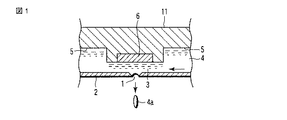
図1にインク循環式のインクジェットヘッド11の断面の構成を示している。すなわち、インク吐出用のノズル1を有するオリィフィスプレート2の上面側に、圧力室3が形成されている。この圧力室3は、インク4が通るヘッド内流路5の中途部が狭められることにより形成され、上記ノズル1を有すると共に、そのノズル1と対向する側の面にアクチュエータ6を有している。インク4は、ヘッド内流路5を図示右側から左側へと、圧力室3を通って流れる。
[1] First embodiment
DESCRIPTION OF EXEMPLARY EMBODIMENTS Hereinafter, a first embodiment of the invention will be described with reference to the drawings.
FIG. 1 shows a cross-sectional configuration of an ink circulation type
上記アクチュエータ6が駆動されることにより、圧力室3内のインク4がインク滴4aとなってノズル1から吐出される。アクチュエータ6としては、PZT等の圧電素子を用いて圧力室3を直接又は間接的に変形させるものが知られている。さらに、インクジェットヘッドとして、静電気でダイアフラムを駆動するもの、ヒータでインクを加熱して気泡を生成し圧力を発生させるもの、インク4を静電気で直接的に移動させるものなど、そのいずれを用いてもよい。なお、上述のアクチュエータ6を設ける位置は、ノズル1と対向する側の面に限らず、例えば、図の奥行き方向に位置する面であってもよい。また、必ずしも圧力室3のインク4が直接ノズル1から吐出するようになっている必要はなく、アクチュエータ6を駆動して圧力室3に圧力を発生させた時にノズル1からインク4が吐出するように、圧力室3とノズル1が連通していれば良い。
When the
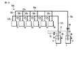
全体的な構成を図2に示している。
第1圧力源である第1インクタンク12が設けられている。第1インクタンク12は、インクジェットヘッド11の圧力室3に供給するためのインク4を収容するとともに、第1気圧源12aを付属して備え、インク4にノズル1の開口の高さ位置の大気圧の静止インクを基準とする、「単位体積当たりのエネルギー」P1(N・m/m3)を生じさせる。単位N・m/m3は、Pa(パスカル)に等しい。この「単位体積当たりのエネルギー」P1(Pa)は、“ベルヌーイの式”の「単位体積当たりのエネルギー」のことであり、静圧、動圧およびポテンシャル圧力の合計値である。以下の説明では、特に断らない限り、ポテンシャル圧力の基準高さは、ノズル1の開口の高さ位置とし、「単位体積当たりのエネルギー」の基準はノズル1の開口の高さ位置の大気圧の静止インクとする。
The overall configuration is shown in FIG.
A
動圧が無視できるとき、「単位体積当たりのエネルギー」P1は、第1インクタンク12内の液面のインク4の静圧Pi1と、第1インクタンク12内のインク4の液面のポテンシャル圧力“ρ・g・h1”との合計値“Pi1+ρ・g・h1”で表わされる。ρ(kg/m3)は、インク4の密度である。g(m/s2)は、インク4の重力加速度である。h1(m)は、ノズル1の開口の高さ位置を基準とする、第1インクタンク12内のインク4の液面の高さ位置、いわゆるポテンシャルヘッドである。後で説明するように、この実施形態では、“h1=0”となるように制御しているので、“Pi1=P1”である。
When the dynamic pressure is negligible, the “energy per unit volume” P1 is the static pressure Pi1 of the
この第1インクタンク12内のインク4が、第1インク流路13aにより、インクジェットヘッド11の流入側インク接続ポートに導かれる。導かれたインク4は、インクジェットヘッド11の圧力室3を通り、流出側インク接続ポートから第2インク流路13bに流出する。第2インク流路13bに流出したインク4は、第2圧力源である第2インクタンク14に導かれる。
The
第2インクタンク14は、インクジェットヘッド11の圧力室3から流出するインク4を収容するとともに、第2気圧源14aを付属して備え、インク4に、「単位体積当たりのエネルギー」P2(Pa)を生じさせる。
The
動圧が無視できるとき、「単位体積当たりのエネルギー」P2は、第2インクタンク14内の液面のインク4の静圧Pi2と、第2インクタンク14内のインク4の液面のポテンシャル圧力“ρ・g・h2”との合計値“Pi2+ρ・g・h2”で表わされる。h2(m)は、ノズル1の開口の高さ位置を基準とする第2インクタンク14内のインク4の液面の高さ位置、いわゆるポテンシャルヘッドである。後で説明するように、この実施形態では、“h2=0”となるように制御しているので、“Pi2=P2”である。
When the dynamic pressure is negligible, the “energy per unit volume” P2 is the static pressure Pi2 of the
ここで、第1インクタンク12内のインク4の“ベルヌーイの式”の「単位体積当たりのエネルギー」について補足説明しておく。
Here, the “energy per unit volume” of the “Bernoulli equation” of the
前で説明したように、第1インクタンク12内の液面のインク4の圧力と、“ベルヌーイの式”の「単位体積当たりのエネルギー」は、ともにP1(=Pi1)である。
As described above, the pressure of the
また、第1インクタンク12内の液面のインク4のポテンシャル圧力は0である。
Further, the potential pressure of the
次に、第1インクタンク12内で液面よりxだけ潜った場所のインク4について、“ベルヌーイの式”の「単位体積当たりのエネルギー」を考えてみる。液面よりx(m)だけ潜った場所のインク4の圧力は液面より“ρ・g・x”だけ増加し、“P1+ρ・g・x”となる。一方、液面よりxだけ潜った場所のインク4のポテンシャル圧力は、液面より“ρ・g・x”だけ減少し、“−ρ・g・x”となっている。したがって、液面よりxだけ潜った場所のインク4の“ベルヌーイの式”の「単位体積当たりのエネルギー」は、これら“P1+ρ・g・x”および“−ρ・g・x”を合計して、“P1+ρ・g・x−ρ・g・x=P1”となり、液面よりxだけ潜った場所でも液面のそれと変わらない。液面からxだけ潜ったことによってポテンシャルエネルギーが圧力エネルギーに置き換わっただけで、エネルギーの総量は変わらないからである。以上、第1インクタンク12内のインク4の“ベルヌーイの式”の「単位体積当たりのエネルギー」について説明したが、第2インクタンク14内のインク4の“ベルヌーイの式”の「単位体積当たりのエネルギー」についても、同様である。一般に、容器内の流路抵抗とインクの運動エネルギーが無視できるとき、“ベルヌーイの定理”によって、容器内のインクの“ベルヌーイの式”の「単位体積当たりのエネルギー」は、液面からの深さに関わらず、容器内のどこでも一様である。従って、この容器内のインクを、“ベルヌーイの式”の「単位体積当たりのエネルギー」を生じさせる圧力源と見なすことができる。
Next, let us consider the “energy per unit volume” of the “Bernoulli equation” for the
例えば、仮に、上記容器にフレキシブルなチューブを接続してインクを取出そうとするとき、接続する取出口の高さ位置によって上記チューブの入口に加わる圧力は変化するが、上記チューブの入口のポテンシャル圧力は同時に上記圧力とは逆符号で同じだけ変化をする。そのため、インクを取出そうとする上記チューブから先の負荷が変わらなければ、上記チューブに流れ込むインクの流量は、上記容器のどの高さ位置からインクを取出しても同じで、上記容器内のインクの“ベルヌーイの式”の「単位体積当たりのエネルギー」と上記チューブから先の負荷とによって定まる。 For example, if a flexible tube is connected to the container and ink is taken out, the pressure applied to the tube inlet varies depending on the height of the connecting outlet, but the potential pressure at the tube inlet is changed. At the same time, the pressure changes by the same amount with the opposite sign. Therefore, if the load ahead of the tube from which the ink is to be taken out does not change, the flow rate of the ink flowing into the tube is the same regardless of the height of the vessel from which the ink is taken out. It is determined by the “energy per unit volume” of the “Bernoulli equation” and the load from the tube.
さて、第2インクタンク14と第1インクタンク12との間には、第3インク流路13cが設けられている。第3インク流路13cには、第2ポンプ17およびフィルタ18が設けられており、第2ポンプ17の動作によってインク4を第1インクタンク12に送る。フィルタ18は、第3インク流路13c内を流れるインク4に混入している異物を除去する。
Now, a third
第1インクタンク12、第1インク流路13a、インクジェットヘッド11、第2インク流路13b、第2インクタンク14、第3インク流路13c、第2ポンプ17、およびフィルタ18により、インク4の循環路が形成されている。
The
また、インク4が収容され且つ大気圧に開放されたメインタンク15が設けられている。このメインタンク15と上記第3インク流路13c(上記第2インクタンク14に近い側)との間に、第4インク流路13dが設けられている。
A
第1インクタンク12に、その内部のインク4の液面の高さ位置を検知する第1液面センサ19が設けられている。第2インクタンク14に、その内部のインク4の液面の高さ位置を検知する第2液面センサ20が設けられている。これら液面センサ19,20の検知結果がCPU10に供給される。
The
上記第4インク流路13dに、第1ポンプ16が設けられている。第1ポンプ16は、CPU10によって制御されることにより、上記第2液面センサ20で検知される高さ位置が、インクジェットヘッド11のノズル1の開口の高さ位置と同じになるように、上記循環路内のインク4の量を増減する。即ち、上記第2液面センサ20で検知される高さ位置が、インクジェットヘッド11のノズル1の開口の高さ位置よりも低い間上記循環路にインク4を送り、上記第2液面センサ20で検知される高さ位置が、インクジェットヘッド11のノズル1の開口の高さ位置よりも高い間は、上記循環路からメインタンク15にインク4を戻す。
A
一方、第2ポンプ17は、上記第1液面センサ19で検知される高さ位置が、インクジェットヘッド11のノズル1の開口の高さ位置と同じになるように、CPU10によって制御される。即ち、上記第1液面センサ19で検知される高さ位置が、インクジェットヘッド11のノズル1の開口の高さ位置よりも低い間は第2ポンプ17を加速又は駆動し、上記第1液面センサ19で検知される高さ位置が、インクジェットヘッド11のノズル1の開口の高さ位置よりも高い間は、第2ポンプ17を減速又は停止する。
On the other hand, the
こうして、第1インクタンク12内のインク4の液面、および第2インクタンク14内のインク4の液面が、インクジェットヘッド11のノズル1の開口と同じ高さ位置に保たれる。
In this way, the liquid level of the
第1インクタンク12内のインク4の「単位体積当たりのエネルギー」P1および第2インクタンク14内のインク4の「単位体積当たりのエネルギー」P2は、気圧源12aの気圧および気圧源14aの気圧とそれぞれ一致している。これらの気圧はCPU10によって制御されている。
The “energy per unit volume” P1 of the
ここで、“P1>P2”に設定すれば、第1インクタンク12内のインク4が、インクジェットヘッド11の圧力室3のノズル1近傍を通って、第2インクタンク14に流れる。同時に、第2インクタンク14内のインク4は、第3インク流路13c、第2ポンプ17、およびフィルタ18を介して第1インクタンク12に戻り、上記循環路内を循環する。
Here, if “P1> P2” is set, the
このようなインクジェットヘッド11に対するインク供給系では、上記循環路内の各所の動圧は、十分小さいので無視できる。また、上記循環路内の各所のレイノルズ数も十分小さいので、インク4の乱流の影響も無視できる。
In such an ink supply system for the
以下、ノズル1におけるインク4の「単位時間当たりの吐出量」が、圧力室3におけるインク4の流量に比べて十分小さい場合について、説明を続ける。この場合、インクジェットヘッド11に対するインク供給系およびインクジェットヘッド11内の圧力損失は、インク吐出量よりも循環流量に大きく左右される。
Hereinafter, the description will be continued in the case where the “ejection amount per unit time” of the
第1インクタンク12から圧力室3のノズル1近傍を経由して第2インクタンク14に至るインク流路を流れるインク4の流量Q(m3/sec)は、第1インクタンク12から圧力室3のノズル1近傍までのインク4の流路抵抗がR1(Pa・sec/m3)、圧力室3のノズル1近傍から第2インクタンク14までのインク4の流路抵抗がR2(Pa・sec/m3)の場合、下式(1)で表わされる。
Q=(P1−P2)/(R1+R2)……(1)
すなわち、インク流量Qは、流路抵抗R1,R2、および第1インクタンク12内のインク4の「単位体積当たりのエネルギー」P1と第2インクタンク14内のインク4の「単位体積当たりのエネルギー」P2との差、により定まる。
The flow rate Q (m 3 / sec) of the
Q = (P1-P2) / (R1 + R2) (1)
That is, the ink flow rate Q corresponds to the flow path resistances R1 and R2 and the “energy per unit volume” P1 of the
流路抵抗R1,R2は、インク4の粘度と流路形状によって決まってしまう。このため、インク流量Qを所望の値に調整するためには、「単位体積当たりのエネルギー」P1,P2の値を調整する。すなわち、CPU10は、気圧源12aの気圧および気圧源14aの気圧のいずれか一方または両方を調整することによってP1,P2の値を調整し、これにより所望のインク流量Qを得る。例えば、「単位体積当たりのエネルギー」P1を大きくするか、あるいは「単位体積当たりのエネルギー」P2を小さくすれば、インク流量Qを増やすことができる。逆に、「単位体積当たりのエネルギー」P1を小さくするか、あるいは「単位体積当たりのエネルギー」P2を大きくすれば、インク流量Qを減らすことができる。
The channel resistances R1 and R2 are determined by the viscosity of the
同時に、CPU10は、「単位体積当たりのエネルギー」P1,P2の関係を下式(2)のように保つ。ここで、Pnは、定数である。
P2={(R1+R2)/R1}×Pn−(R2/R1)×P1……(2)
インク4を吐出しないとき、ノズル1の開口近傍におけるインク4の圧力(Pa)は、“P2+Q×R2”である。この“P2+Q×R2”に上式(1)(2)を代入すると、下式(3)のように展開される。
P2+Q×R2
=P2+{(P1−P2)/(R1+R2)}×R2
={1−R2/(R1+R2)}×P2+{R2/(R1+R2)}×P1
={R1/(R1+R2)}×P2+{R2/(R1+R2)}×P1
=Pn−{R1/(R1+R2)×(R2/R1)×P1}
+{R2/(R1+R2)}×P1
=Pn……(3)
すなわち、定数Pnは、ノズル1の開口近傍におけるインク4の圧力(Pa)に相当するもので、ノズル1の開口におけるインクの表面がその開口の内側に湾曲するメニスカス(図1参照)を保つように、例えば0(Pa)〜−3000(Pa)の範囲に含まれる値が選定される。仮に、定数Pnが、0(Pa)より大きいとノズル1からインク4が漏れてしまう虞があり、−3000(Pa)より小さいとノズル1に余計な空気が引き込まれてしまう虞がある。以下、定数Pnのことを、ノズル1の開口近傍におけるインク4の適正圧力と称する。
At the same time, the
P2 = {(R1 + R2) / R1} × Pn− (R2 / R1) × P1 (2)
When the
P2 + Q × R2
= P2 + {(P1-P2) / (R1 + R2)} * R2
= {1-R2 / (R1 + R2)} * P2 + {R2 / (R1 + R2)} * P1
= {R1 / (R1 + R2)} × P2 + {R2 / (R1 + R2)} × P1
= Pn− {R1 / (R1 + R2) × (R2 / R1) × P1}
+ {R2 / (R1 + R2)} × P1
= Pn (3)
That is, the constant Pn corresponds to the pressure (Pa) of the
ノズル1の開口近傍におけるインク4の圧力は、インク4の吐出動作を行っている間は、吐出のために、高い周波数で大きく変化する。しかし、インク4を吐出するときは、吐出のためにメニスカスを意図的に壊すのであるから、ここで維持すべきノズル1の開口近傍におけるインク4の適正圧力Pnは、吐出動作のための高周波成分を除く平均値、あるいは吐出動作と次の吐出動作との間の休止時間中の圧力を意味する。
The pressure of the
ノズル1の開口近傍におけるインク4の圧力は、厳密に言えば圧力室3のノズル1近傍の圧力に、圧力室3のノズル1近傍とノズル1の開口近傍との間の僅かな高低差に起因するポテンシャル圧力を加えた値である。
Strictly speaking, the pressure of the
なお、流路抵抗R1,R2の関係が“R1=R2”であれば、「単位体積当たりのエネルギー」P2の上式(2)は、下式(4)のように、より単純になる。
P2=2・Pn−P1……(4)
また、流路抵抗R1と流路抵抗R2との比を“1:r”と表せば(つまりR2/R1=r)、「単位体積当たりのエネルギー」P2の上式(2)は、下式(5)のようになる。
P2={(1+r)×Pn}−(r×P1)……(5)
すなわち、ノズル1の開口近傍におけるインク4の適正圧力Pnを維持するための「単位体積当たりのエネルギー」P1,P2の関係は、流路抵抗R1,R2の絶対値に影響されず、流路抵抗R1と流路抵抗R2との比“1:r”だけで決定される。
If the relationship between the channel resistances R1 and R2 is “R1 = R2,” the upper equation (2) of “energy per unit volume” P2 becomes simpler as the lower equation (4).
P2 = 2 · Pn−P1 (4)
Further, if the ratio between the channel resistance R1 and the channel resistance R2 is expressed as “1: r” (that is, R2 / R1 = r), the upper equation (2) of “energy per unit volume” P2 is expressed by the following equation: It becomes like (5).
P2 = {(1 + r) × Pn} − (r × P1) (5)
That is, the relationship between the “energy per unit volume” P1 and P2 for maintaining the appropriate pressure Pn of the
従来のインクジェット装置では、圧力源とインクジェットヘッドとを接続する流路の流路抵抗に生じる圧力損失が大きい場合、ノズル1の開口近傍におけるインク4の圧力を適正圧力に維持することは困難であった。特に、例えば、圧力源とインクジェットヘッドとを接続する流路の流路抵抗に生じる圧力損失(厳密に言えば、インク4の「単位体積当たりのエネルギー」の損失)が「ノズル1の開口近傍におけるインク4の適正圧力の範囲」の大きさ(レンジ)の半分以上を占めるような場合、即ち例えば圧力源とインクジェットヘッドとを接続する流路の流路抵抗にこの流路の流量を乗じた値が1500(Pa)を超えるような場合はノズル1の開口近傍におけるインク4の圧力を適正圧力に維持することがきわめて困難であった。しかし本発明によれば、ノズル1の開口近傍におけるインク4の圧力は流路抵抗R1,R2の絶対値に影響されず、流路抵抗R1と流路抵抗R2との比“1:r”だけで決定されるので、流路抵抗R1と流路抵抗R2による圧力損失が例えば合計3000(Pa)を超えていても、ノズル1の開口近傍におけるインク4の圧力を適正圧力に維持することができる。
In the conventional ink jet apparatus, when the pressure loss generated in the flow path resistance of the flow path connecting the pressure source and the ink jet head is large, it is difficult to maintain the pressure of the
また、周囲温度の違いによってインク4の粘度が変化した場合、あるいは粘度の異なる別の種類のインク4が使用された場合、流路抵抗R1,R2の絶対値は変化する。しかしながら、流路抵抗R1と流路抵抗R2との比“1:r”は、循環路内のインク4の粘度が一様であれば、インク流路13a,13bの物理的形状を変えない限り、一定に保たれる。すなわち、CPU10が上式(5)を保つように「単位体積当たりのエネルギー」P1,P2の関係を制御すれば、周囲温度やインク4の種類が違っても、圧力室3のノズル1近傍の圧力は一定に保たれる。
Further, when the viscosity of the
例えば、ノズル1より上流側のインク流路13aの断面積とノズル1より下流側のインク流路13bの断面積が同じであれば、インク流路13aの長さとインク流路13bの長さとの比が、すなわち流路抵抗R1と流路抵抗R2との比“1:r”に相当するので、その比を用いる上式(5)に基づいて「単位体積当たりのエネルギー」P2を設定すればよい。その結果、ノズル1の開口近傍におけるインク4の圧力を適正圧力Pnに保つことができる。
For example, if the cross-sectional area of the
流路抵抗R1,R2の絶対値が変わればインク流量Qは変化するが、圧力室3を流れるインク4の動圧が小さく且つ圧力室3のレイノルズ数が小さければ、
圧力の変化も乱流の影響も無視できるので、インク流量Qが急激に変化しない限り、インク流量Qの変化はインク4の吐出動作に直接影響しない。これに対して、ノズル1の開口近傍におけるインク4の圧力は、直接、インク4の吐出動作に影響する。よって、インク流量Qを保つことよりも、ノズル1の開口近傍におけるインク4の圧力を適正に保つことの方が、より重要で、優先すべき条件である。
If the absolute values of the flow path resistances R1 and R2 change, the ink flow rate Q changes, but if the dynamic pressure of the
Since the change in pressure and the influence of turbulent flow can be ignored, the change in the ink flow rate Q does not directly affect the ejection operation of the
とはいえ、インク流量Qが大きく変化し過ぎると、使用するポンプの能力不足やインクタンクの容量不足、インク4の循環による利点であるインク温度の均一化効果や気泡除去効果の減少、などの問題が生じてしまう。そこで、インク流量Qの変化が大きくなり過ぎることを防ぐために、インク4の粘度に応じて、第1インクタンク12の「単位体積当たりのエネルギー」P1を補正してもよい。
Nonetheless, if the ink flow rate Q changes too much, the capacity of the pump to be used, the capacity of the ink tank is insufficient, the effect of equalizing the ink temperature and the effect of removing the bubbles, which are the advantages of the circulation of the
インク流量Qを表わす上式(1)は、「単位体積当たりのエネルギー」P2の代わりに流路抵抗比rと定数Pnを用いれば、下式(6)のように展開される。
Q=(P1−P2)/(R1+R2)
=(1+r)(P1−Pn)/(R1+R2)……(6)
仮に、インク4の粘度が上がって“R1+R2”が増大した場合には、“P1−Pn”が大きくなるように「単位体積当たりのエネルギー」P1を大きくしつつ、上式(5)に従って「単位体積当たりのエネルギー」P2を調整することによって、インク流量Qの変化を防ぐことができる。
The above equation (1) representing the ink flow rate Q is developed as the following equation (6) when the flow resistance ratio r and the constant Pn are used instead of the “energy per unit volume” P2.
Q = (P1-P2) / (R1 + R2)
= (1 + r) (P1-Pn) / (R1 + R2) (6)
If the viscosity of the
インク流量Q、および流路抵抗R1,R2の合成抵抗である全流路抵抗Rを用いると、与えるべき「単位体積当たりのエネルギー」P1は、下式(7)で表される。
P1=Q・R/(1+r)+Pn……(7)
全流路抵抗Rはインク4の粘度に比例するので、この式(7)を用いることにより、「単位体積当たりのエネルギー」P1をインク4の粘度に応じて調整しつつ、上式(5)に従って「単位体積当たりのエネルギー」P2を調整すれば、インク流量Qの変化を防ぐことができる。なお、既に述べた理由により、この調整はそれほど厳密さを要求されない。また、この調整を行っても行わなくても、上式(2)(4)(5)のいずれかの条件に従って「単位体積当たりのエネルギー」P2を設定する制御を採用すれば、ノズル1の開口近傍におけるインク4の圧力を適正圧力Pnに保つことができる。
ここでは、「単位体積当たりのエネルギー」P1の増減によってインク流量Qを調節し、かつ適正圧力Pnが得られるように「単位体積当たりのエネルギー」P2を設定する場合について説明したが、逆に「単位体積当たりのエネルギー」P2の増減によってインク流量Qを調節し、かつ適正圧力Pnが得られるように「単位体積当たりのエネルギー」P1を設定してもよい。
When the total flow resistance R, which is the combined resistance of the ink flow rate Q and the flow resistances R1 and R2, is used, the “energy per unit volume” P1 to be given is expressed by the following equation (7).
P1 = Q · R / (1 + r) + Pn (7)
Since the total channel resistance R is proportional to the viscosity of the
Here, the case where the ink flow rate Q is adjusted by increasing or decreasing the “energy per unit volume” P1 and the “energy per unit volume” P2 is set so as to obtain an appropriate pressure Pn has been described. The “energy per unit volume” P1 may be set so that the ink flow rate Q is adjusted by increasing / decreasing the “energy per unit volume” P2 and the appropriate pressure Pn is obtained.
上式(2)(4)(5)では、ノズル1の開口近傍におけるインク4の適正圧力を得るための「単位体積当たりのエネルギー」P2の値を「単位体積当たりのエネルギー」P1の関数として与えたが、逆に、上記各式を「単位体積当たりのエネルギー」P1について解いて、ノズル1の開口近傍におけるインク4の適正圧力を得るための「単位体積当たりのエネルギー」P1の値を「単位体積当たりのエネルギー」P2の関数として与えてもよい。要は、「単位体積当たりのエネルギー」P1,P2の関係が、上式(2)(4)(5)のいずれかを満足していればよい。
In the above equations (2), (4), and (5), the value of “energy per unit volume” P2 for obtaining an appropriate pressure of the
なお、「単位体積当たりのエネルギー」P1を大きくしてインク流量Qを増大させ、これにより、インクジェットヘッド11内に存する異物および気泡などを下流側へ押し流すメンテナンスが可能である。この間も、上式(2)(4)(5)のいずれかの条件に従って「単位体積当たりのエネルギー」P2を設定する制御を行い続けることにより、ノズル1の開口近傍におけるインク4の圧力を適正圧力Pnに保つことができる。したがって、メンテナンス中に、ノズル1からインク4が漏れることがなく、ノズル1内に不要な空気が流入することもない。すなわち、ノズル1の開口におけるインク4のメニスカスを壊すことなく、無駄のない効率的なメンテナンスが可能である。
In addition, the "energy per unit volume" P1 is increased to increase the ink flow rate Q, and thereby maintenance that allows foreign matter and bubbles existing in the
インクジェットヘッド11内に存する異物および気泡などを下流側へ押し流すためには、インク流量Qができるだけ大きい方がよい。しかしながら、常に最大のインク流量Qが維持されると、ポンプ17の寿命に悪影響を与えたり、ポンプ17から騒音が生じたり、インク流路13a,13b,13cが劣化したり、フィルタ18が劣化したり、インク4に不要なストレスが加わったり、インク流路13a,13b,13cのいずれかの箇所から気泡が混入してそれがインクジェットヘッド11に送られてしまうなどの懸念がある。このため、インク流量Qについては、必要な時だけ、増大させる使い方が望ましい。本実施形態の場合、インク流量Qを変えた場合でもノズル1の開口近傍におけるインク4の圧力を適正圧力Pnに制御できるので、そのような使い方(インク流量Qを必要な時だけ増大させる使い方)が可能である。
In order to push away foreign matters and bubbles existing in the
また、メンテナンスに際しては、ノズル1の開口近傍におけるインク4の圧力を故意に通常の適正圧力Pnよりも大きく設定して、インク4をノズル1から強制的に吐出させることにより、ノズル1の開口の周縁をインク4で濡らしたり、ノズル1の開口の内側に存する異物(インク4の固形化物を含む)をノズル1の外に押し出したり、ノズル1の開口の周縁に付着した異物を取除くなどの処置が可能である。
During maintenance, the pressure of the
ところで、複数のインクジェットヘッド11が搭載されている場合、第1インクタンク12から複数のインク流路13aをそれぞれ介して各インクジェットヘッド11にインク4が導かれ、そして、各インクジェットヘッド11を経たインク4が複数のインク流路13bをそれぞれ介して第2インクタンク14に導かれるように構成することができる。この場合、複数のインク流路13aの太さと長さが互いに同じで、しかも、複数のインク流路13bの太さと長さが互いに同じであれば、複数のインクジェットヘッド11に流れるインク4の流量とノズル1の開口近傍におけるインク4の圧力を各々一致させることができる。
By the way, when a plurality of inkjet heads 11 are mounted, the
しかし、一般には、第1インクタンク12および第2インクタンク14に近い位置に置かれたインクジェットヘッド11および遠い位置に置かれたインクジェットヘッド11が混在するので、複数のインク流路13aの長さを一致させること、あるいは複数のインク流路13bの長さを一致させることは、困難なことが多い。
However, in general, since the
この場合、第1インクタンク12から各インクジェットヘッド11の圧力室3のノズル1近傍までのインク4の流路抵抗をR11,R12,R13,…とし、各インクジェットヘッド11の圧力室3のノズル1近傍から第2インクタンク14までのインク4の流路抵抗をR21,R22,R23,…と表せば、“R21/R11=R22/R12=R23/R13=…”の条件を満たすことにより、各インクジェットヘッド11の間で流量は必ずしも互いに同一ではないが、各インクジェットヘッド11のノズル1の開口近傍におけるインク4の圧力を互いに同じ値に保つことができる。このとき、第1インクタンク12から各インクジェットヘッド11の圧力室3のノズル1近傍までのインク4の流路抵抗と各インクジェットヘッド11の圧力室3のノズル1近傍から第2インクタンク14までのインク4の流路抵抗の比をR21/R11=R22/R12=R23/R13=…=rとして上式(2)又は(5)に従ってP1,P2の関係を制御するか、さらにr=1として上式(4)に従ってP1,P2の関係を制御すれば、各インクジェットヘッド11のノズル1の開口近傍におけるインク4の適正圧力を維持することができる。
In this case, the flow resistance of the
なお、インクジェットヘッド11としては、1つのノズル1を有するものに限らず、インク4の流れ方向と直交する方向(図1の奥行き方向)に配列された複数の圧力室3と複数のノズル1を有するものがある。複数の圧力室3と複数のノズル1を有するインクジェットヘッド11の場合、インクジェットヘッド11の流入側インク接続ポートから各圧力室3のノズル1近傍までの流路抵抗をZ11,Z12,Z13,…とし、各圧力室3のノズル1近傍からインクジェットヘッド11の流出側インク接続ポートまでの流路抵抗をZ21,Z22,Z23,…と表せば、“Z21/Z11=Z22/Z12=Z23/Z13=…”の条件を満たすことにより、各ノズル1の開口近傍におけるインク4の圧力を互いに同じ値に保つことができる。
The
ここまでは、ノズル1におけるインク4の単位時間当たりのインク吐出量が循環流量に比べて十分に小さくてその影響が無視できる範囲の動作を検討したが、単位時間当たりのインク吐出量の影響が無視できない場合は、上記の構成に単位時間当たりのインク吐出量の影響を重ね合わせて考えればよい。
Up to this point, the operation in a range where the ink discharge amount per unit time of the
すなわち、上記のインク供給系の吐出流量に対する圧力変動を考えるとき、このインク供給系は適正圧力Pnの圧力源から流路抵抗R1,R2の並列抵抗である“(R1×R2)/(R1+R2)”の流路抵抗を介して供給する供給系と等価と考えることができる。つまり、ノズル1からインク4が吐出されるとき、ノズル1の開口近傍におけるインク4の圧力は、流路抵抗R1,R2の並列抵抗にインク4が流れることによって生じる圧力損失の分だけ、適正圧力Pnよりも増大する。このときの圧力損失が許容できる程度に、流路抵抗R1,R2の絶対値を設定すればよい。
That is, when considering the pressure fluctuation with respect to the discharge flow rate of the ink supply system, the ink supply system is a parallel resistance of the flow path resistances R1 and R2 from the pressure source of the appropriate pressure Pn “(R1 × R2) / (R1 + R2)”. It can be considered to be equivalent to a supply system that is supplied via a flow path resistance of "". That is, when the
ただし、圧力室3のノズル1近傍からノズル1の開口近傍までの流路抵抗に起因する圧力損失については、通常、吐出のためにアクチュエータ6の動作を設定する際に考慮されるので、ここでは考慮しないものとする。
However, since the pressure loss due to the flow resistance from the vicinity of the
また、ここまでは、ノズル1付近のインク4の流れに起因する動圧は無視できるものとして説明したが、より厳密には、ノズル1付近のインク4の流速を算出し、この流速の動圧による圧力低下分だけ、適正圧力Pnを高めてもよい。
In the above description, the dynamic pressure caused by the flow of the
以上のように、インク流量Qの変化にかかわらず、また複雑な制御や大きなエネルギー消費を要することもなく、ノズル1の開口近傍におけるインク4の圧力を常に適正圧力Pnに維持することができる。
As described above, the pressure of the
[2]第2の実施形態
インク4が第1インクタンク12からヘッドを経由して第2インクタンク14に向かう方向に循環するとき、P1>P2である。メインタンク15内のインク4の「単位体積当たりのエネルギー」が、「単位体積当たりのエネルギー」P1と「単位体積当たりのエネルギー」P2との間にあれば、図3に示すように、第1ポンプ16に代えて、第5インク流路22、第1バルブ21、第2バルブ23を採用して、インク供給系を簡略化することができる。
[2] Second embodiment
When the
第5インク流路22は、第3インク流路13cの第1インクタンク12に近い側の部位と第4インク流路13dとの間に設けられている。
The fifth
第5インク流路22と第3インク流路13cの接続点は、第1インクタンク12に十分近い場所に設ける。このとき接続点のインクの「単位体積あたりのエネルギー」はほぼP1と見なせる。
The connection point between the fifth
第3インク流路13cと第4インク流路13dの接続点は、第2インクタンク14に十分近い場所に設ける。このとき接続点のインクの「単位体積あたりのエネルギー」はほぼP2と見なせる。
The connection point between the
第1バルブ21は、第4インク流路13dにおける第3インク流路13cの接続位置と第5インク流路22の接続位置との間に、設けられている。第2バルブ23は、第5インク流路22に設けられている。そして、第1バルブ21および第2バルブ23は、CPU10の制御により、第2液面センサ20で検知される高さ位置(第2インクタンク14内のインク4の液面の高さ位置)が、インクジェットヘッド11のノズル1の開口の高さ位置と同じになるように、循環路内のインク4の量を増減する。
The
第2ポンプ17は、第1の実施形態と同様に、第1液面センサ19で検知される第1インクタンク12内のインク4の液面の高さ位置に従って制御されている。
Similarly to the first embodiment, the
第2液面センサ20で検知される第2インクタンク14内のインク4の液面の高さ位置が、インクジェットヘッド11のノズル1の開口の高さ位置に満たない場合は、バルブ21を開いて、第2インクタンク14にインク4を補給する。
When the height position of the liquid level of the
一方、第2液面センサ20で検知される第2インクタンク14内のインク4の液面の高さ位置が、インクジェットヘッド11のノズル1の開口の高さ位置よりも高い場合は、バルブ23を開いて、第1インクタンク12からインク4を吸い出す。その際、一旦、第1インクタンク12内のインク4の液面は低下するが、このとき第2ポンプ17が作動して第1インクタンク12内のインク4の液面を戻し、同時に第2インクタンク14内のインク4の液面を下げる。
On the other hand, when the height position of the liquid level of the
このように、バルブ21,23の開閉によって、第1の実施形態と同様に、第2インクタンク14内のインク4の液面をノズル1の開口の高さ位置に制御することができる。
As described above, the liquid level of the
本実施形態の構成では、循環路内のインク4の増量は、
{メインタンク15から第4インク流路13d、バルブ21を介して、第3インク流路13cに至る経路の流路抵抗、
および
メインタンク15内のインク4の「単位体積当たりのエネルギー」と第2インクタンク14内のインク4の「単位体積当たりのエネルギー」P2との差、}
によって定まる流量で行われる。
In the configuration of the present embodiment, the increase in the amount of
{Flow path resistance of the path from the
and
Difference between “energy per unit volume” of
The flow rate is determined by
循環路内のインク4の減量は、
{メインタンク15から第4インク流路13d、バルブ23、第5インク流路22を介して、第3インク流路13cに至る経路の流路抵抗、
および
メインタンク15内のインク4の「単位体積当たりのエネルギー」と第1インクタンク12内のインク4の「単位体積当たりのエネルギー」P1との差、}
によって定まる流量で行われる。
The weight loss of
{Flow path resistance of the path from the
and
Difference between “energy per unit volume” of
The flow rate is determined by
他の構成および作用は、第1の実施形態と同じである。よって、その説明は省略する。 Other configurations and operations are the same as those in the first embodiment. Therefore, the description is omitted.
[3]第3の実施形態
図4に示すように、第1圧力源として、インクジェットヘッド11の圧力室3に供給されるインク4を収容し且つ大気開放された第1インクタンク12が採用されている。この第1インクタンク12が、インクジェットヘッド11のノズル1の開口より高い位置に配置されている。第1インクタンク12液面のインク4に生じる「単位体積当たりのエネルギー」P1は、ポテンシャル圧力だけであり、ノズル1の開口の高さ位置を基準とする第1インクタンク12内のインク4の液面の高さ位置に応じて、定まる。図4中の“P1/(ρ・g)”は、このポテンシャルヘッド(m)である。
[3] Third embodiment
As shown in FIG. 4, a
第2圧力源として、インクジェットヘッド11の圧力室3から流出するインク4を収容し且つ大気開放された第2インクタンク14が採用されている。この第2インクタンク14が、インクジェットヘッド11のノズル1の開口より低い位置に配置されている。第2インクタンク14内のインク4に生じる「単位体積当たりのエネルギー」P2は、ポテンシャル圧力だけであり、
ノズル1の開口の高さ位置を基準とする第2インクタンク14内のインク4の液面の高さ位置に応じて、定まる。図4中の“−P2/(ρ・g)”は、このポテンシャルヘッド(m)である。
As the second pressure source, a
It is determined according to the height position of the liquid level of the
すなわち、ノズル1の開口の高さ位置と第1インクタンク12内のインク4の液面の高さ位置の高低差を“P1/(ρ・g)”(m)に設定し、ノズル1の開口の高さ位置と第2インクタンク14内のインク4の液面の高さ位置の高低差を“−P2/(ρ・g)”(m)に設定することによって、第1の実施形態と同じ動作となる。
That is, the height difference between the height position of the opening of the
他の構成および作用は、第1の実施形態と同じである。よって、その説明は省略する。 Other configurations and operations are the same as those in the first embodiment. Therefore, the description is omitted.
なお、ここの実施例では第1圧力源と第2圧力源の両方を大気開放してポテンシャル圧力によってP1,P2を生成したが、第1圧力源と第2圧力源のうちどちらか片方に本実施形態の形態を採用し、他方は第1の実施形態を採用するように組み合わせて応用することも可能である。 In this embodiment, both the first pressure source and the second pressure source are opened to the atmosphere and P1 and P2 are generated by the potential pressure. However, the first pressure source and the second pressure source may be connected to either one of the first pressure source and the second pressure source. It is also possible to adopt the form of the embodiment and apply the other in combination so as to adopt the first embodiment.
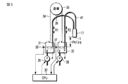
[4]第4の実施形態
図5に示すように、第1圧力源として、インクジェットヘッド11の圧力室3に供給されるインク4を収容し且つ大気開放された第1インクタンク31が設けられている。この第1インクタンク31内のインク4の液面の高さ位置(第1インクタンク31に対する相対高さ)が第1インクタンク31に設置された第1液面センサ35によって検知される。この第1液面センサ35の検知結果がCPU30に供給される。CPU30は、第1液面センサ35で検知される高さ位置が予め定められている高さ位置と同じになるように、ポンプ36を制御して図示しないインクタンクと第1インクタンク31との間でインク4を出入りさせて、第1インクタンク31内のインク4の量を増減する。この第1インクタンク31とインクジェットヘッド11の流入側インク接続ポートとの間に、フレキシブルな液送チューブを用いた第1インク流路39が設けられている。
[4] Fourth embodiment
As shown in FIG. 5, a
第2圧力源として、インクジェットヘッド11の圧力室3から流出するインク4を収容し且つ大気開放された第2インクタンク32が設けられている。この第2インクタンク32内のインク4の液面の高さ位置(第2インクタンク32に対する相対高さ)が第2インクタンク32に設置された第2液面センサ37によって検知される。この第2液面センサ37の検知結果がCPU30に供給される。CPU30は、第2液面センサ37で検知される高さ位置が予め定められている高さ位置と同じになるように、ポンプ38を制御して図示しないインクタンクと第2インクタンク32との間でインク4を出入りさせて、第2インクタンク32内のインク4の量を増減する。この第2インクタンク32とインクジェットヘッド11の流出側インク接続ポートとの間に、フレキシブルな液送チューブを用いた第2インク流路41が設けられている。
As a second pressure source, a
そして、滑車33に紐34が掛けられ、その紐34の両端に第1インクタンク31および第2インクタンク32がそれぞれ吊るされている。滑車33の回転位置により、第1インクタンク31の高さ位置および第2インクタンク32の高さ位置が変化する。
A
図5は、第1インクタンク31内のインク4の液面および第2インクタンク32内のインク4の液面が、共にノズル1の開口よりも“−Pn/(ρ・g)”だけ下にある状態を示している。このとき、ノズル1の開口近傍におけるインク4に生じる圧力は、適正圧力Pnである。
FIG. 5 shows that the liquid level of the
ここでは、第1インクタンク31から圧力室3のノズル1近傍までの流路抵抗R1と、圧力室3のノズル1近傍から第2インクタンク32までの流路抵抗R2との関係は、“R1=R2(=R0)”としている。
Here, the relationship between the flow path resistance R1 from the
この状態は、インク4の循環が無いインクジェット装置において、ポテンシャル圧力を用いてノズル1の開口近傍におけるインク4の適正圧力(負圧)を維持するものが2セット並列になっている状態と考えることができ、このままインク4を循環させずに印字することも可能である。
This state is considered to be a state in which two sets of ink jet apparatuses that do not circulate the
次に、この状態から図6に示すように滑車33を右に回す。
第1インクタンク31が距離“Px/(ρ・g)”だけ上昇すると、第2インクタンク32が距離“Px/(ρ・g)”だけ下降し、インクジェットヘッド11の圧力室3内のインク4に流れが生じる。このときのインク流量Qは、上記R0(=R1=R2)を用いて、“Q=Px/R0”で表わされる。
Next, from this state, the
When the
第1インクタンク31から圧力室3のノズル1近傍までの流路抵抗による「単位体積当たりのエネルギー」の損失(Pa)は、“R0・Q”で表わされ、第1インクタンク31が距離“Px/(ρ・g)”だけ上昇したことによって生じる第1インクタンク31内のインク4の「単位体積当たりのエネルギー」P1の増加量Pxと等しい。また、圧力室3のノズル1近傍から第2インクタンク32までの流路抵抗による「単位体積当たりのエネルギー」の損失(Pa)は、“R0・Q”で表わされ、第2インクタンク32が距離“Px/(ρ・g)”だけ下降したことによって生じる第2インクタンク32内のインク4の「単位体積当たりのエネルギー」P2の減少量Pxと等しい。
The loss (Pa) of “energy per unit volume” due to the flow path resistance from the
したがって、ノズル1の開口近傍におけるインク4の圧力は、変化せず、適正圧力Pnを維持する。
Therefore, the pressure of the
インク流量Qは滑車33の回転位置によって調整できるが、その調整中も、調整後も、ノズル1の開口近傍におけるインク4の圧力は変動しない。つまり、ノズル1の開口近傍におけるインク4の圧力は、インク流量Qに関係なく、常に適正圧力Pnに維持される。
The ink flow rate Q can be adjusted by the rotational position of the
なお、流路抵抗R1,R2の関係が“R1=R2(=R0)”の場合を例に説明したが、流路抵抗R1,R2の比が“1:r”の場合は、滑車33に代えて、第1インクタンク31の上昇距離と第2インクタンク32の下降距離との比が“1:r”の関係になる昇降機構を用いればよい。
Although the case where the relationship between the channel resistances R1 and R2 is “R1 = R2 (= R0)” has been described as an example, when the ratio between the channel resistances R1 and R2 is “1: r”, the
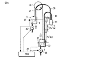
[5]第5の実施形態
図7に示すように、インク循環式の複数のインクジェットヘッド51,52,53,54,55,56が互いに同じ高さ位置にほぼ水平状態に配列されている。これらインクジェットヘッド51〜56は、基本的な構成は図1に示したインクジェットヘッド11と同じである。ただし、インクジェットヘッド51〜56の圧力室3は、各々636個あって、各圧力室3は各々1個のノズル1と連通している。この636個の圧力室3およびノズル1が、その各圧力室3におけるインク4の流れ方向と直交する方向(図1の奥行き方向)に配列されている。
[5] Fifth embodiment
As shown in FIG. 7, a plurality of ink-jet heads 51, 52, 53, 54, 55, and 56 are arranged in a substantially horizontal state at the same height position. These ink jet heads 51 to 56 have the same basic configuration as the
インクジェットヘッド51〜56の個々のインク吐出能力は、1ヘッドすなわち636ノズルあたり0.167(mL/sec)である。また、インクジェットヘッド51〜56における各圧力室3は、断面の周長が7.6×10−4(m)、断面積が2.4×10−8(m2)である。
The individual ink discharge capacities of the inkjet heads 51 to 56 are 0.167 (mL / sec) per head, that is, 636 nozzles. Each
第1圧力源として、インクジェットヘッド51〜56に供給するためのインク4を収容した上流側インクタンク58、およびその上流側インクタンク58の空間領域にエアーパイプ76を介して連通された正圧エアータンク65が設けられている。上流側インクタンク58は、内部のインク4に「単位体積当たりのエネルギー」P1を生じさせる。この「単位体積当たりのエネルギー」P1は、上流側インクタンク58内のインク4の液面の高さ位置、および正圧エアータンク65内の空気圧PS1の大きさによって、定まる。なお、上記エアーパイプ76は、エアーバルブ78を備えている。
As a first pressure source, an
上流側インクタンク58内のインク4は、第1インク流路57により、インクジェットヘッド51〜56のそれぞれ流入側インク接続ポートに導かれる。導かれたインク4は、インクジェットヘッド51〜56のそれぞれの圧力室3を通って流出側インク接続ポートから第2インク流路59に流出する。第2インク流路59に流出したインク4は、第2圧力源に導かれる。
The
第2圧力源として、インクジェットヘッド51〜56から流出するインク4を収容する下流側インクタンク60、およびその下流側インクタンク60の空間領域にエアーパイプ77を介して連通された負圧エアータンク66が設けられている。下流側インクタンク60は、内部のインク4に「単位体積当たりのエネルギー」P2を生じさせる。この「単位体積当たりのエネルギー」P2は、下流側インクタンク60内のインク4の液面の高さ位置、および負圧エアータンク66内の空気圧PS2の大きさによって、定まる。
As a second pressure source, a
上流側インクタンク58および下流側インクタンク60は、各々断面積が5(cm2)で、容積が25(mL)である。
The
上記第1インク流路57は、インクジェットヘッド51〜56の配列方向に沿ってほぼ水平状態に設けられた流路(第1流路)57aと、この流路57aから分岐してインクジェットヘッド51〜56の流入側インク接続ポートにそれぞれ接続される複数の流路(第2流路)57bと、上記流路57aから下方に延びて上流側インクタンク58に連通される流路(第3流路)57cとで形成されている。
The
上記第2インク流路59は、インクジェットヘッド51〜56の配列方向に沿ってほぼ水平状態に設けられた流路(第4流路)59aと、この流路59aから分岐してインクジェットヘッド51〜56の流出側インク接続ポートにそれぞれ接続される複数の流路(第5流路)59bと、上記流路59aから下方に延びて下流側インクタンク60に連通される流路(第6流路)59cとで形成されている。流路59cに、開閉用のバルブ84が設けられている。
The second ink channel 59 includes a channel (fourth channel) 59a provided in a substantially horizontal state along the arrangement direction of the inkjet heads 51 to 56, and the inkjet heads 51 to 51 branching from the
下流側インクタンク60と上流側インクタンク58との間に、第3インク流路79が設けられている。第3インク流路79には、ポンプ62およびインク4に混入している異物を除去するフィルタ63が設けられている。
A third
上流側インクタンク58、第1インク流路57、インクジェットヘッド51〜56、第2インク流路59、第3インク流路79、ポンプ62、およびフィルタ63により、インク4の循環路が形成されている。
The
また、インク4が収容され且つ大気開放されたメインタンク61が設けられている。このメインタンク61と上記第3インク流路79(下流側インクタンク60に近い側)との間に、第4インク流路81が設けられている。
A
上流側インクタンク58に、その内部のインク4の液面の高さ位置を検知する第1液面センサ85が設けられている。下流側インクタンク60に、その内部のインク4の液面の高さ位置を検知する第2液面センサ86が設けられている。
The
上記第3インク流路79における上記第4インク流路81の接続位置より下流側インクタンク60に近い側に、流路を開閉するためのバルブ80が設けられている。さらに、第4インク流路81に、バルブ82が設けられている。
A
メインタンク61内のインクの「単位体積当たりのエネルギー」は循環中のインクの、上記第3インク流路79と上記第4インク流路81の接続位置の、「単位体積当たりのエネルギー」よりも大きくなるように設定されている。
The “energy per unit volume” of the ink in the
上記正圧エアータンク65に第1圧力センサ67が設けられ、上記負圧エアータンク66に第2圧力センサ68が設けられている。第1圧力センサ67は、正圧エアータンク65内の空気圧PS1を検知する。第2圧力センサ68は、負圧エアータンク66内の空気圧PS2を検知する。
A
上記正圧エアータンク65にエアーパイプ70の一端が接続され、そのエアーパイプ70の他端が大気に開放されている。エアーパイプ70には、排気用のリークバルブ72および吸排気用のエアーバルブ73が設けられている。リークバルブ72には開放時の空気の流速を制限する空気抵抗が設けられている。上記負圧エアータンク66にエアーパイプ71の一端が接続され、そのエアーパイプ71の他端が大気に開放されている。エアーパイプ71には、吸気用のリークバルブ74および吸排気用のエアーバルブ75が設けられている。リークバルブ74には開放時の空気の流速を制限する空気抵抗が設けられている。
One end of an
エアーパイプ71におけるリークバルブ74とエアーバルブ75との間の位置にエアーパイプ76の一端が接続され、そのエアーパイプ76の他端がエアーパイプ70におけるリークバルブ72とエアーバルブ73との間の位置に接続されている。そして、エアーパイプ76にエアーポンプ69が設けられている。
One end of the
エアーポンプ69は、エアーパイプ71側の空気を吸込み、吸込んだ空気をエアーパイプ70側に送り込む。このエアーポンプ69の動作、リークバルブ72,74の動作、およびエアーバルブ73,75の動作により、正圧エアータンク65内の気体分子数および負圧エアータンク66内の気体分子数がそれぞれ調節される。
The
ノズル1の開口近傍におけるインク4の適正圧力をPnとすれば、上流側インクタンク58内のインク4の液面の高さ位置および下流側インクタンク60内のインク4の液面の高さ位置は、共に、適正圧力Pnと等しいポテンシャル圧力を生じる高さ位置、すなわちノズル1の開口の高さ位置よりも“−Pn/(ρ・g)”だけ下に設定しておく(Pnは負値なので、−Pn/(ρ・g)は正値)。
If the proper pressure of the
上流側インクタンク58は、「単位体積当たりのエネルギー」P1の圧力源として働く。この場合の「単位体積当たりのエネルギー」P1は、下式(8)で表される。
P1=Pn+PS1……(8)
この式(8)を正圧エアータンク65内の空気圧PS1について解けば、下式(9)が得られる。
PS1=P1−Pn……(9)
下流側インクタンク60は、「単位体積当たりのエネルギー」P2の圧力源として働く。この場合の「単位体積当たりのエネルギー」P2は、下式(10)で表される。
P2=Pn+PS2……(10)
この式(10)を負圧エアータンク66内の空気圧PS2について解けば、下式(11)が得られる。
PS2=P2−Pn……(11)
ここで、ノズル1の開口近傍のインク4の圧力を適正圧力Pnに保つには、第1の実施形態で説明した式(5)と、上式(9)(11)を用いて、空気圧PS1,PS2の関係を下式(12)のように定めればよい。
PS2=P2−Pn
=(r×Pn)−(r×P1)
=−r×(P1−Pn)
=−r×PS1……(12)
すなわち、CPU50は、第1圧力センサ67で検知される圧力PS1と第2圧力センサ68で検知される圧力PS2が、上式(12)を保つように正圧エアータンク65内の気体分子数および負圧エアータンク66内の気体分子数のいずれか一方あるいは両方を増減すればよい。
The
P1 = Pn + PS1 (8)
If this equation (8) is solved for the air pressure PS1 in the positive
PS1 = P1-Pn (9)
The
P2 = Pn + PS2 (10)
Solving this equation (10) for the air pressure PS2 in the negative
PS2 = P2-Pn (11)
Here, in order to keep the pressure of the
PS2 = P2-Pn
= (R * Pn)-(r * P1)
= -R * (P1-Pn)
= -R x PS1 (12)
That is, the
ただし、上記rは、上流側インクタンク58から各圧力室3のノズル1近傍までのインク4の流路抵抗と、各圧力室3のノズル1近傍から下流側インクタンク60までのインク4の流路抵抗と、の比である。
Where r is the flow resistance of the
なお、この第5の実施形態においては、流路57c,57a,59c,59aは、複数のインクジェットヘッド51〜56に共用されている。この共用部分の流路抵抗は、上流側インクタンク58から各圧力室3のノズル1近傍までのインク4の流路抵抗および各圧力室3のノズル1近傍から下流側インクタンク60までのインク4の流路抵抗を計算する際に、インクジェットヘッド51〜56に按分して考える。また、インクジェットヘッド51〜56の各々の内部にも通常は複数の圧力室3に共用される流路部分が存在するが、この共用部分についても、同じ考え方で、各圧力室3に按分利用されているものとして考えることができる。按分の方法については、後で説明する。
In the fifth embodiment, the
特に、r=1であるとき、上式(12)は更に簡単になって下式(13)となる。
PS2=−PS1……(13)
すなわち、この場合、CPU50は、第1圧力センサ67で検知される圧力PS1と第2圧力センサ68で検知される圧力PS2の関係を、大きさが同じで符号が反対になるように正圧エアータンク65内の気体分子数および負圧エアータンク66内の気体分子数のいずれか一方あるいは両方を増減すればよい。
In particular, when r = 1, the above equation (12) is further simplified to the following equation (13).
PS2 = -PS1 (13)
That is, in this case, the
一方、循環路を流れるインク4の総循環流量は、検知圧力PS1と検知圧力PS2との差の増減によって調整できる。つまり、検知圧力PS1と検知圧力PS2との差が大きければ総循環流量が増大し、検知圧力PS1と検知圧力PS2との差が小さければ総循環流量が減少する。本実施形態では、表計算を用いて、循環路を流れるインク4の総循環流量が所望の値となるように、調整する。この調整の方法については、後で述べる。
On the other hand, the total circulation flow rate of the
上流側インクタンク58、下流側インクタンク60、およびその周辺部に対し、ラジエータ64および冷却ファン83が設けられている。このラジエータ64および冷却ファン83により、上流側インクタンク58、下流側インクタンク60、およびその周辺部が冷却される。
A
第1インク流路57および第2インク流路59の具体的な構成を図11に示している。
A specific configuration of the
使用されるインク4は、粘度が10(m・Pa・sec)で、比重が0.85すなわち密度ρは850(kg/m3)である。
The
ほぼ水平状態に配置される流路57a,59aは、例えば、内寸が3×10(mm)で、各流路57b,57c,59b,59cとの分岐点のひとつと、その隣の分岐点との間の長さが55(mm)の扁平管である。分岐する各流路57b,59bは、内径が3(mm)と、細めのフレキシブルなチューブである。ほぼ垂直方向に延びる流路57c,59cは、長さが250(mm)で、内径が4(mm)と、太めの円管である。
The
各流路57bおよびその各流路57bからインクジェットヘッド51〜56の各ノズル1近傍までの流路の流路抵抗はR1、流路57aの各分岐点間の流路抵抗はR2、流路57cの流路抵抗をR3とする。インクジェットヘッド51〜56の各圧力室3のノズル1近傍から各流路59bまでの流路およびその各流路59bにおける流路抵抗はR1´、流路59aの各分岐点間の流路抵抗をR2´、流路59cの流路抵抗はR3´とする。
The flow path resistance of each
これら流路抵抗は、
“R1=R1´=1.67×10⁹(Pa・sec/m3)”、
“R2=R2´=3.01×10⁷(Pa・sec/m3)”、
“R3=R3´=3.98×10⁸(Pa・sec/m3)”である。
These channel resistances are
“R1 = R1 ′ = 1.67 × 10 9 (Pa · sec / m 3 )”,
“R2 = R2 ′ = 3.01 × 10 7 (Pa · sec / m 3 )”,
“R3 = R3 ′ = 3.98 × 10 8 (Pa · sec / m 3 )”.
このとき、インクジェットヘッド51〜56の各ノズル1近傍より上流側のインク4の流路抵抗と、インクジェットヘッド51〜56の各ノズル1近傍より下流側のインク4の流路抵抗との比は、“1:1”で、即ちここでは流路抵抗比r=1である。
At this time, the ratio between the flow path resistance of the
インク流路57,59の太さおよび形状は、以下に説明するような考え方で選定されている。仮に、インク流路57,59に細めの円管を使用すると、インク流路57,59の流路抵抗が大きいためにインクの吐出流量の影響を受け易く、インクジェットヘッド51〜56からのインク4の吐出性能や安定性に悪影響を及ぼしてしまう。逆に、インク流路57,59に太目の円管を使用すると、インク4の充填時、各流路の随所に気泡が残り易くなる。また、インク流路57,59があまりに太ければ、物理的に配置が困難になるという問題もある。これらの点を考慮して、インク流路57,58は、場所によってその形状と太さを変えている。
The thickness and shape of the
扁平管を用いた流路57a,59aは、高さを3(mm)に抑えることによって上部に気泡が残り難くしながら、幅を広めにとることによって流路抵抗を抑えている。
The
鉛直方向に延びる流路57c,59cは、気泡を上部に浮かせることができるように、内径が4(mm)と太目の円管を採用している。浮かせた気泡は、流路57c,59cの最上部に図示しない気泡排出バルブを設け、この気泡排出バルブにシリンジ等を接続することにより、吸い出してもよい。また、上方に浮かせた気泡を、インク充填時の充填手順やインク送り速度の条件を選ぶことで、流路抵抗に影響がない程度に、小さくしてもよい。円管を採用した流路57cにおける上部の気泡は、扁平管を採用した流路57aからインクジェットヘッド51〜56に向かってインク4とともに流すことにより、インクジェットヘッド51〜56のノズル1から排出してもよい。
The
一方、各流路57b,59bは、インクジェットヘッド51〜56ごとに独立した流路であり、流量が少ないためある程度の流路抵抗は許容できるので、流路抵抗よりもインク4の充填し易さ、すなわち気泡の排出し易さを優先して、インクを流す方向にインクとともに気泡を押し流せるように、内径が3(mm)と細めのチューブを使用している。このような構成において、インク4の総循環流量を1×10⁻⁵(m3/sec)に設定する。
On the other hand, each of the
適正圧力Pnは例えば−1300(Pa)であり、従って上流側インクタンク58内のインク4の液面および下流側インクタンク60内のインク4の液面は、各ノズル1の開口より“−Pn/(ρ・g)”、即ち156(mm)だけ下に調整されている。
The appropriate pressure Pn is, for example, −1300 (Pa). Therefore, the liquid level of the
図7において、流路59a,57aにおけるインクジェットヘッド52用の流路59b,57bの接続点から図示左側のインク流路(インクジェット51に接続されるインク流路59a,59b,57a,57bと、インクジェットヘッド51とを含む)の合成流路抵抗をRt1とする。この合成流路抵抗Rt1の箇所を図8に太線で示している。さらに流路59a,57aにおけるインクジェットヘッド53用の流路59b,57bの接続点から図示左側のインク流路(インクジェットヘッド51,51に接続されるインク流路59a,59b,57a,57bと、インクジェットヘッド51,52とを含む)の流路抵抗をRt2とする。この合成流路抵抗Rt2の箇所を図9に太線で示している。同様に、流路59a,57aにおけるインクジェットヘッド54用の流路59b,57bの接続点から図示左側のインク流路(インクジェットヘッド51,51,52,53に接続されるインク流路59a,59b,57a,57bと、インクジェットヘッド51,52,53とを含む)の流路抵抗をRt3とし、流路59a,57aにおけるインクジェットヘッド55用の流路59b,57bの接続点から図示左側のインク流路(インクジェットヘッド51,52,53,54に接続されるインク流路59a,59b,57a,57bと、インクジェットヘッド51,52,53,54とを含む)の流路抵抗をRt4とし、流路59a,57aにおけるインクジェットヘッド56用の流路59b,57bの接続点から図示左側のインク流路(インクジェットヘッド51,52,53,54,55に接続されるインク流路59a,59b,57a,57bと、インクジェットヘッド51,52,53,54,55とを含む)の流路抵抗をRt5とする。さらに、上流側インクタンク58および下流側インクタンク60からインク流路59、インク流路57およびインクジェットヘッド51〜56を含めた合成流路抵抗をRt6とする。この合成流路抵抗Rt6の箇所を図10に太線で示している。
In FIG. 7, the ink flow paths (
流路57aからインクジェットヘッド51へ流れるインク流量をQ1とし、流路57aからインクジェットヘッド51,52へ流れるインク流量をQ2とし、流路57aからインクジェットヘッド51〜53へ流れるインク流量をQ3とし、流路57aからインクジェットヘッド51〜54へ流れるインク流量をQ4とし、流路57aからインクジェットヘッド51〜55へ流れるインク流量をQ5とし、流路57aから全てのインクジェットヘッド51〜56へ流れるインク流量(インク4の総循環流量)をQ6とする。
The ink flow rate flowing from the
流路59aにおける各インクジェットヘッド51〜56用の流路59bの接続点と、流路57aにおける各インクジェットヘッド51〜56用の流路57bの接続点の高さがほぼ等しいものとして、流路59aにおけるインクジェットヘッド51用の流路59bの接続点と流路57aにおけるインクジェットヘッド51用の流路57bの接続点との間の圧力差をPd1とし、流路59aにおけるインクジェットヘッド52用の流路59bの接続点と流路57aにおけるインクジェットヘッド52用の流路57bの接続点との間の圧力差をPd2とし、流路59aにおけるインクジェットヘッド53用の流路59bの接続点と流路57aにおけるインクジェットヘッド53用の流路57bの接続点との間の圧力差をPd3とし、流路59aにおけるインクジェットヘッド54用の流路59bの接続点と流路57aにおけるインクジェットヘッド54用の流路57bの接続点との間の圧力差をPd4とし、流路59aにおけるインクジェットヘッド55用の流路59bの接続点と流路57aにおけるインクジェットヘッド55用の流路57bの接続点との間の圧力差をPd5とし、流路59aにおけるインクジェットヘッド56用の流路59bの接続点と流路57aにおけるインクジェットヘッド56用の流路57bの接続点との間の圧力差をPd6とする。なお、上流側インクタンク58内のインク4の「単位体積当たりのエネルギー」P1と下流側インクタンク60のインク4の「単位体積当たりのエネルギー」P2との差はPd7とする。
It is assumed that the connection points of the
インクジェットヘッド51におけるインク流量をQh1とし、インクジェットヘッド52におけるインク流量をQh2とし、インクジェットヘッド53におけるインク流量をQh3とし、インクジェットヘッド54におけるインク流量をQh4とし、インクジェットヘッド55におけるインク流量をQh5とし、インクジェットヘッド56におけるインク流量をQh6とする。
The ink flow rate in the
R1,R1´,R2,R2´,R3,R3´の値から算出した流路抵抗Rt1〜Rt6の値、およびこの流路抵抗Rt1〜Rt6とインク流量Q1〜Q6、圧力差Pd1〜Pd7、インク流量Qh1〜Qh6との関係式を入力した表計算シートを作成して、インク4の総循環流量Q6が“Q6=1×10⁻⁵(m3/sec)”となるように数値を調整すると、この表計算シートは図12に示すような値となる。
The values of the channel resistances Rt1 to Rt6 calculated from the values of R1, R1 ′, R2, R2 ′, R3 and R3 ′, the channel resistances Rt1 to Rt6 and the ink flow rates Q1 to Q6, the pressure differences Pd1 to Pd7, the ink When a spreadsheet is input with the relational expression between the flow rates Qh1 to Qh6, and the numerical value is adjusted so that the total circulation flow rate Q6 of the
すなわち、上流側インクタンク58内のインク4の「単位体積当たりのエネルギー」P1と下流側インクタンク60内のインク4の「単位体積当たりのエネルギー」P2との差Pd7を、14993(Pa)とする必要がある。
That is, the difference Pd7 between the “energy per unit volume” P1 of the
上式(4)の条件“P2=2・(−1300)−P1”を満たしながら「単位体積当たりのエネルギー」P1,P2の差Pd7を14993(Pa)とするためには、P1=6196(Pa)、P2=−8796(Pa)とすればよい。
このとき、PS1=−PS2=7496(Pa)である。
In order to set the difference Pd7 between “energy per unit volume” P1 and P2 to 14993 (Pa) while satisfying the condition “P2 = 2 · (−1300) −P1” of the above equation (4), P1 = 6196 ( Pa), P2 = −8796 (Pa).
At this time, PS1 = −PS2 = 7496 (Pa).
上流側インクタンク58にインク4を送るポンプ62は、上流側インクタンク58内のインク4の液面の高さ位置(第1液面センサ85で検知される高さ位置)が、予め定められている高さ位置よりも高いとき回転数が低減され、予め定められている高さ位置より低いとき回転数が増大される。上流側インクタンク58内のインク4の液面の高さ位置が予め定められている高さ位置と同じとき、ポンプ62の送液量は、総循環流量の設定値である“1×10⁻⁵(m3/sec)”に一致する。
In the
バルブ82は、下流側インクタンク60内のインク4の液面の高さ位置(第2液面センサ86で検知される高さ位置)が、予め定められている高さ位置よりも低い場合に開かれる。これにより、メインタンク61内のインク4が下流側インクタンク60に補給される。この補給速度は、約5(mL/sec)に設定されている。この補給速度は、第3インク流路79と第4インク流路81の接続位置のインク4の「単位体積当たりのエネルギー」、メインタンク61内のインク4の「単位体積当たりのエネルギー」、およびバルブ82を含む第4インク流路81の流路抵抗に応じて決定されるので、これらの関係を、補給速度が約5(mL/sec)になるように調整すればよい。
The
第2液面センサ86が高さ位置を検知してからバルブ82が動作するまでの応答遅れは、0.1(sec)である。この応答遅れを含む液面高さの調節精度は、±5(mm)である。従って、この高さ精度に対応するポテンシャル圧力変化は±42(Pa)であって、この圧力変化の幅は各ノズル1開口近傍のインク4の適正圧力Pnである−1300(Pa)の絶対値に比べて十分小さくなっている。
The response delay from when the second
正圧エアータンク65内の気体分子数および負圧エアータンク66内の気体分子数を調節するためのエアーポンプ69、リークバルブ72,74、およびエアーバルブ73,75の動作を図13に示している。
The operations of the
すなわち、7つの動作パターンがあり、これら動作パターンのいずれかが圧力センサ67,68の検知結果に応じて選択的に実行されることにより、正圧エアータンク65の圧力PS1を+7496(Pa)、負圧エアータンク66の圧力PS2を−7496(Pa)に維持することができる。正圧エアータンク65の圧力PS1については、+7496(Pa)を目指す制御が実行される。負圧エアータンク66の圧力PS2については、−7496(Pa)を直接的に目指す制御ではなく、圧力PS1の変化に伴って“−PS1”を逐次に目指す制御が実行される。これにより、正圧エアータンク65の圧力PS1が+7496(Pa)に到達するまでの過程において、各ノズル1の開口近傍におけるインク4の圧力が適正圧力Pnである−1300(Pa)からずれない。
That is, there are seven operation patterns, and any one of these operation patterns is selectively executed according to the detection results of the
図13の5番目の動作パターンでは、ポンプ69が停止されて、正圧エアータンク65および負圧エアータンク66がそれぞれ大気にリークされる。この状態に至るまでに、図13の6番目および7番目の動作パターンが実行される。すなわち、正圧エアータンク65の圧力PS1が0(Pa)を目指して調節され、この調節に伴い、負圧エアータンク66の圧力PS2が“−PS1”となるように調節される。正圧エアータンク65および負圧エアータンク66のリークが終了すると、正圧エアータンク65の圧力PS1および負圧エアータンク66の圧力PS2が共に大気圧となる。このとき、インクジェットヘッド51〜56の各ノズル1には、ポテンシャル圧力である−1300(Pa)が加わり続ける。この状態は、何も制御することなく適正圧力Pnを維持できる。この状態にしておけば、印刷装置が通電されていなくてもメニスカスが維持され、停電等があっても温度や気圧が変化してもメニスカスの湾曲状態が変わることが無く、また、シャットダウン等の際にノズルからインクが垂れることも空気が入ってしまうことも無く、次の電源投入時に迅速に通常動作に入ることができる。
In the fifth operation pattern of FIG. 13, the
以上の制御により、インクジェットヘッド51〜56の各ノズル1の開口近傍におけるインク4の圧力が、常に適正圧力Pnである−1300(Pa)を維持する。すなわち、インク流量に関係なく、各ノズル1の開口近傍におけるインク4の圧力を常に適正圧力Pnに維持できる。
With the above control, the pressure of the
(a)上流側の気体体積と下流側の気体体積ついて補足説明する。
上流側インクタンク58の空間領域とエアーパイプ76、正圧エアータンク65の容積を合計した上流側の気体体積と、下流側インクタンク60の空間領域とエアーパイプ77と負圧エアータンク66の容積を合計した下流側の気体体積と、を等しく設定しておくと、さらに都合が良い。図13の5番目の動作パターンで大気開放した後図13の1番目の動作パターンでエアーポンプ69を作動させると、エアーポンプ69の作動中も作動終了後も常に上流側の気体分子数の増加量と下流側の気体分子数の減少量は等しく、かつ体積は変化しない。このため、上流側の気体体積と下流側の気体体積とを等しくしておけば、第1圧力センサ67と第2圧力センサ68を使った制御を行わなくてもエアーポンプ69を作動させるだけで式(13)のPS2=−PS1の条件を維持したままインクを循環できる。エアーポンプ69を逆転させれば式(13)のPS2=−PS1の条件を維持したまま循環流量を減らし、循環を止めることも可能である。従って上流側の気体体積と下流側の気体体積とを等しくしておけば、図13の他の動作パターン、即ち2番目,3番目,4番目,6番目,7番目の動作パターンの使用を、各接続部からの空気漏れなどによる僅かなアンバランスを補正する場合のみの動作に限定することができ、パターン切り替え頻度を減らすことができるので、システムの信頼性が向上する。或いは5番目の動作パターンで大気開放してから次回に5番目の動作パターンで大気開放するまでの間の、各部からのエアリークが無視できるような使い方であれば、図13の2番目,3番目,4番目,6番目,7番目の動作パターンを省いてしまうことも可能で、その場合、エアーバルブ73,75を省略でき、かつ第1圧力センサ67および第2圧力センサ68も精度の低いものにするか、どちらか片方を省略するか、或いは正圧エアータンク65と負圧エアータンク66の差圧の測定で済ませることができるので、装置を簡単で安価なものにすることができる。この実施形態では流路抵抗比r=1であるため「上流側の気体体積と下流側の気体体積とを等しく設定しておくとさらに都合が良い」としたが、一般に上流側と下流側の流路抵抗比が“1:r”であるときは、上流側の気体体積と下流側の気体体積との比をr:1としておけば上記説明と同様の効果を得られる。又、本実施形態では、初期状態が大気開放、すなわちPS1=PS2=0であるが、一般に初期状態がPS1=PS2=(所定値)である場合においても、上流側の気体体積と下流側の気体体積との比をr:1としておけばエアーポンプ69を作動させるだけでノズル開口近傍のインク圧力を変えずに循環流量を制御できるので、この技術は上流側インクタンク58及び下流側インクタンク60の液面高さ位置がノズル1の開口高さ位置よりも“−Pn/(ρ・g)”だけ下に設定してある場合以外であっても応用可能である。
(A) The gas volume on the upstream side and the gas volume on the downstream side will be supplementarily described.
The upstream gas volume obtained by adding up the space area of the
(b)各インクジェットヘッドにおけるインク流量について説明する。
インク4の総循環流量が1×10⁻⁵(m3/sec)であるとき、インクジェットヘッド51〜56の個々におけるインク流量Qh1〜Qh6の値を知るには、図12の表計算シートを見ればよい。
(B) The ink flow rate in each inkjet head will be described.
When the total circulation flow rate of the
図12の表計算シートによれば、インク流量Qh1〜Qh6の値は、1.50×10⁻⁶(m3/sec)〜1.93×10−6(m3/sec)の間でばらつくが、インク4の総循環流量はインク4の吐出動作に直接影響しないので、この程度のばらつきは問題ない。実際に、この考え方で、インク流量Qを0(m3/sec)から1.93×10−6(m3/sec)までの範囲で変化させながらプリント結果を比較したが、プリント結果の差異は全く区別できなかった。
According to spreadsheet in FIG. 12, the value of the ink flow Qh1~Qh6 is varied between 1.50 × 10 -6 (m 3 /sec)~1.93×10 -6 (
(c)各インクジェットヘッドの圧力室の動圧について説明する。
インクジェットヘッド51〜56の各圧力室3は、上記したように、それぞれ636個のノズル1を有している。圧力室3は、2.4×10⁻⁸(m2)の断面積を持っている。
(C) The dynamic pressure in the pressure chamber of each inkjet head will be described.
Each
インクジェットヘッド51〜56に対するインク4の循環量が1.93×10⁻⁶(m3/sec)のとき、インクジェットヘッド51〜56の各圧力室3を流れるインク4の流量は3.03×10−9(m3/sec)、流速は0.126(m/sec)となる。この流速による動圧は、
[850(kg/m3)×0.1262(m/sec)]/2=6.7(Pa)
とごく僅かであり、ノズル1の開口近傍におけるインク4の適正圧力Pnである−1300(Pa)の絶対値に比べて十分に小さく、無視することができる。或いは、前述のように、最初から適正圧力Pnをこの6.7(Pa)だけ高く設定しておいてもよい。
When the circulation amount of the
[850 (kg / m 3 ) × 0.126 2 (m / sec)] / 2 = 6.7 (Pa)
It is extremely small and sufficiently smaller than the absolute value of −1300 (Pa), which is the appropriate pressure Pn of the
(d)各インクジェットヘッドの圧力室の乱流について説明する。
各圧力室3の周長を7.6×10⁻⁴(m)、インク4の粘度を10(mPa・sec)、インク4の比重0.85と、インクジェットヘッド51〜56の各圧力室3を流れるインク4の流量3.03×10⁻⁹(m3/sec)を用いてレイノルズ数Reを計算すると、
Re=(4×3.03×10−9)/{(0.01/850)
×7.6×10−4}=1.36
となる。このレイノルズ数Reの値、1.36は十分に小さく、乱流の影響が無視できる値である。
(D) The turbulent flow in the pressure chamber of each inkjet head will be described.
The circumference of each
Re = (4 × 3.03 × 10 −9 ) / {(0.01 / 850)
× 7.6 × 10 −4 } = 1.36
It becomes. The value of this Reynolds number Re, 1.36, is sufficiently small so that the influence of turbulence can be ignored.
(e)インクの温度制御について説明する。 (E) Ink temperature control will be described.
インクジェットヘッド51〜56は、動作中(プリント中)に発熱する。この発熱に伴い、インク4の温度が変化する。インク4の温度が大きく変わると、インク吐出特性に影響を及ぼしてしまう。この温度変化に対処するため、上記したラジエータ64および冷却ファン83が採用されている。
The ink jet heads 51 to 56 generate heat during operation (during printing). Along with this heat generation, the temperature of the
ラジエータ64および冷却ファン83の具体的な構成を図14に示している。ラジエータ64は、アルミニウム製のヒートシンク92を有し、そのヒートシンク92と外気との間で1(℃/W)の熱抵抗による熱交換を可能とする。ヒートシンク92には、上流側インクタンク58および下流側インクタンク60が取付けられている。冷却ファン83は、ヒートシンク92に外気を供給し、ヒートシンク92を冷却する。例えば、インクジェットヘッド51〜56の消費電力から吐出するインクが奪う単位時間当たりの熱量を差し引いた、単位時間当たりエネルギーとして、10Wが循環するインクに与えられるとき、この冷却により、インク4の温度を外気温+10(℃)程度に抑えることができる。
Specific configurations of the
なお、図9において、90はインクジェットヘッド51〜56によってプリントされた用紙が通過する用紙通過部、91は本発明のインクジェット装置が収容された筐体である。この筐体91の側壁のすぐ近くに上記ヒートシンク92が設けられているので、ヒートシンク92を外気によって直接的に効率良く冷却することができる。
In FIG. 9,
仮に、上流側インクタンク58および下流側インクタンク60をインクジェットヘッド51〜56からそれぞれ等しい距離のところに配置しようとすると、その配置場所は筐体91の中心に近くなる。筐体91の中心近くでは、外気による直接的な冷却が困難である。これに対し、本実施形態によれば、必ずしも上流側インクタンク58および下流側インクタンク60をインクジェットヘッド51〜56からそれぞれ等しい距離のところに配置する必要はない。即ち、上流側の流路抵抗と下流側の流路抵抗との比さえ、インクジェットヘッド51〜56のいずれについても同じ値“r”になるようにしておけば、インクジェットヘッド51〜56の各ノズル1の開口近傍におけるインク4の圧力がそれぞれ適正圧力Pnに維持されるので、上流側インクタンク58および下流側インクタンク60を筐体1の端部に寄せて配置することができる。よって、上記のように、筐体91の側壁にヒートシンク92を設け、そのヒートシンク92に上流側インクタンク58および下流側インクタンク60を取付ける構成の採用が可能となっている。
If the
(f)メンテナンスについて説明する。
第1のメンテナンス方法は、上流側インクタンク58内のインク4の「単位体積当たりのエネルギー」P1を22000(Pa)程度まで上昇させるとともに、その「単位体積当たりのエネルギー」P1の変化に伴い、下流側インクタンク60内のインク4の「単位体積当たりのエネルギー」P2を“−P1”となるように調節する。これにより、インクジェットヘッド51〜56の各ノズル1の開口近傍におけるインク4の圧力を適正圧力Pnである−1300(Pa)に保ったまま、インク4の循環量が約3倍まで増加する。インク4の循環によって、インクジェットヘッド51〜56内の異物および気泡が、下流側インクタンク60に流れる。下流側インクタンク60に流れた気泡は浮上して消滅し、下流側インクタンク60に流れた異物はフィルタ63で濾過され、気泡と異物が取り除かれたインクが上流側インクタンク58に戻される。インク4の循環量が増大すると、これらの作用がより効果的に行われる。
(F) The maintenance will be described.
The first maintenance method increases the “energy per unit volume” P1 of the
第2のメンテナンス方法は、下流側インクタンク60内のインク4の「単位体積当たりのエネルギー」P2を“−P1+α”に変更する。これにより、インク4が、インクジェットヘッド51〜56の各ノズル1から溢れ出る。溢れ出たインク4は、吸引ノズルで吸い取るか、ブレードで掻き取る。インク4が溢れ出ることにより、各ノズル1の表面近くにある異物や気泡を取除くことができる。各ノズル1の表面近くに異物や気泡がある場合には、この第2のメンテナンス方法が有効である。
In the second maintenance method, the “energy per unit volume” P2 of the
第3のメンテナンス方法は、流路59cにおけるバルブ84を瞬間的に閉じる。これにより、インク4が、インクジェットヘッド51〜56の各ノズル1から溢れ出る。溢れ出たインク4は、吸引ノズルで吸い取るか、ブレードで掻き取る。各ノズル1を通過するインク4の速さは、第2のメンテナンス方法の場合よりも、第3のメンテナンス方法の場合の方が速い。すなわち、第3のメンテナンス方法は、各ノズル1の内部の汚れに対し、より有効である。
In the third maintenance method, the
但し、圧力室3のノズル1近傍よりも上流側にノズル1よりも大きな異物がある状態で第2のメンテナンス方法および第3のメンテナンス方法を実施すると、ノズル1に異物を詰め込んでしまう虞があるので、第2のメンテナンス方法および第3のメンテナンス方法は第1のメンテナンス方法を実施した後に実施することが望ましい。第4のメンテナンス方法は、これを考慮した各ノズル1の汚れを取る最も強力な方法であり、以下のシーケンスを有する。
先ず、第1のメンテナンス方法と同様に、インク4の循環量を増大する。次に、第2のメンテナンス方法と同様に、ノズル圧力を僅かに正圧側にシフトして、各ノズル1から僅かな量のインク4を溢れ出させる。この状態で、第3のメンテナンス方法と同様に、流路59cにおけるバルブ84を瞬間的に閉じて、各ノズル1からインク4を高速で溢れ出させる。その後、バルブ84を開放状態に戻してから、各ノズル1から溢れ出たインク4を、吸引ノズルで吸い取るか、ブレードで掻き取る。その後、下流側インクタンク60内のインク4の「単位体積当たりのエネルギー」P2を“−P1”に戻してから、再度、各ノズル1の周りに残っているインク4を吸引ノズルで吸い取るか、ブレードで掻き取る。最後に、インク4の循環量を通常に戻す。
However, if the second maintenance method and the third maintenance method are performed in a state where there is a foreign object larger than the
First, as in the first maintenance method, the circulation amount of the
ここで説明した手順は、インクジェット装置のメンテナンスを行う場合に限らず、洗浄液を使ってヘッドを洗浄する場合の洗浄方法として使用することもできる。 The procedure described here is not limited to the maintenance of the inkjet apparatus, but can also be used as a cleaning method when the head is cleaned using a cleaning liquid.
その場合には、洗浄液の消費量が少なく、ノズル1に異物を詰め込んでしまう恐れの無い洗浄方法を提供できる。
In such a case, a cleaning method can be provided in which the consumption of the cleaning liquid is small and there is no fear that the
(g)インク4の充填について説明する。
インクジェットヘッド51〜56、インク流路57,59,79、上流側インクタンク58、および下流側インクタンク60に対し、空の初期状態から、インク4を充填する方法について説明する。初期状態として、メインタンク61にはインク4が十分にあり、正圧エアータンク65および負圧エアータンク66はいずれも大気開放しているものとする。
(G) The filling of the
A method of filling the
バルブ80が閉じられ、バルブ82が開かれ、ポンプ62が所定の回転数で駆動される。これにより、メインタンク61内のインク4が、上流側インクタンク58に供給される。なお、エアーバルブ78およびバルブ84は開かれている。
The
上流側インクタンク58内のインク4が増えて、そのインク4の液面の高さ位置(第1液面センサ85で検知される高さ位置)が、予め定められている高さ位置に達したら、エアーバルブ78が閉じられる。エアーバルブ78が閉じられると、上流側インクタンク58内のインク4が、流路57cを上昇して流路57aに流入する。流路57aに流入したインク4は、各流路57bを通ってインクジェットヘッド51〜56の各圧力室3に流入し、その各圧力室3から各流路59b、流路59a、流路59cを通って下流側インクタンク60に導かれる。
The
このとき、インク4の流量が多過ぎるとインクジェットヘッド51〜56の各ノズル1からインク4が多量に漏れてしまい、インク4の流量が少ないと充填に時間がかかってしまう。このため、インク4の流量は、そのような不都合が生じない適度な値に設定される。なお、インクジェットヘッド51〜56にキャップを被せて、各ノズル1の開口の気密を保っておけば、各ノズル1から溢れるインク4の量を減らすことができる。或いは、インクジェットヘッド51〜56の各ノズル1周囲に液体や異物が無いよう事前に綺麗にしておけば、各ノズル1からインク4が溢れ始める流量(インク4の流量をどこまで大きくすると各ノズル1からインク4が溢れ始めるか?というその流量の値)を大きくすることができる。もしノズル開口部の縁がインクで濡れてたり、開口部の縁に異物があると、わずかな正圧でもインクはノズル開口部の外へ自由に広がって行いってしまう。これに対しノズル開口部の縁が乾いていればインクはノズル開口部に凸状の滴を形成する。この場合、仮に充填時の流量が大きくその結果ノズル開口近傍が正圧になったとしても、その値が滴の表面張力による圧力と平衡がとれる範囲の正圧であれば、インクはノズルから溢れ出さない。従って、先立ってワイプ動作等により各ノズル1周囲を綺麗にしておくことが望ましい。
At this time, if the flow rate of the
下流側インクタンク60内のインク4の液面の高さ位置(第2液面センサ86で検知される高さ位置)が、予め定められている高さ位置に達したら、エアーバルブ78およびバルブ80が開かれ、バルブ82が閉じられる。そして、エアーポンプ69が起動され、インク4の通常の循環動作に移行する。
When the height position of the liquid level of
ここまでは、エアーバルブ78を使用する充填方法について説明したが、エアーバルブ78を使用しない充填方法もある。以下、エアーバルブ78を使用しない充填方法について説明する。
バルブ80が閉じられ、バルブ82が開かれ、ポンプ62が所定の回転数で駆動される。これにより、メインタンク61内のインク4が、上流側インクタンク58に供給される。
Up to this point, the filling method using the
The
上流側インクタンク58内のインク4が増えて、そのインク4の液面の高さ位置(第1液面センサ85で検知される高さ位置)が、予め定められている高さ位置に達したら、その状態が保たれるように、ポンプ62が制御される。例えば、上流側インクタンク58内のインク4の液面の高さ位置が、予め定められている高さ位置より高いとき、ポンプ62が停止される。上流側インクタンク58内のインク4の液面の高さ位置が、予め定められている高さ位置より低いとき、ポンプ62が所定の回転数で駆動される。
The
この制御に伴い、正圧エアータンク65の圧力PS1が増大される。インク4がインク流路57の最高地点を通過するためには、正圧エアータンク65の圧力PS1が、インク流路57の最高地点と上流側インクタンク58内のインク4の液面との間の標高差分のポテンシャル圧力よりも、高いことが必須要件となる。インク4が、インクジェットヘッド51〜56の各圧力室3を通過した後、インク流路59の最高地点を越える際にも、正圧エアータンク65の圧力PS1が、インク流路59の最高地点と上流側インクタンク58内のインク4の液面との間の標高差分のポテンシャル圧力よりも、高いことが必須要件となる。
しかし、正圧エアータンク65の圧力PS1が高過ぎるとインクジェットヘッド51〜56の各ノズル1からインク4が多量に漏れてしまい、正圧エアータンク65の圧力PS1が低いと充填に時間がかかってしまう。このため、正圧エアータンク65の圧力PS1は、そのような不都合が生じない適度な値に設定される。
Along with this control, the pressure PS1 of the positive
However, if the pressure PS1 of the positive
なお、先ずは正圧エアータンク65の圧力PS1を上げ、インク4がインク流路57の最高地点あるいはインク流路59の最高地点を越えた頃を見計らって、正圧エアータンク65の圧力PS1を下げてもよい。なお、インクジェットヘッド51〜56にキャップを被せて、各ノズル1の開口の気密を保っておけば、各ノズル1から溢れるインク4の量を減らすことができる。或いは、インクジェットヘッド51〜56の各ノズル1周囲に液体や異物が無いよう事前に綺麗にしておけば、各ノズル1からインク4が溢れ始める正圧エアータンク65の圧力(正圧エアータンク65の圧力をどこまで大きくすると各ノズル1からインク4が溢れ始めるか?というその圧力の値)を大きくすることができる。
First, the pressure PS1 of the positive
下流側インクタンク60内のインク4の液面の高さ位置(第2液面センサ86で検知される高さ位置)が、予め定められている高さ位置に達したら、バルブ80が開かれ、バルブ82が閉じられる。そして、負圧エアータンク66の圧力PS2が“−PS1”に制御されて、上流側インクタンク58内のインク4の「単位体積当たりのエネルギー」P1が通常値に設定される。これにより、インク4の通常の循環動作に移行する。
When the height position of the liquid level of the
インク4の通常の循環制御に移行するタイミングを、下流側インクタンク60内のインク4の液面の高さ位置が、予め定められている高さ位置に達するタイミングよりも早くすれば、各ノズル1から溢れるインク4の量を減らすことができる。これを実現するためには、第2液面センサ86よりも下方に、もう1つの液面センサを設ければよい。あるいは、充填動作の開始時刻および上流側インクタンク58が液面検知するタイミングのいずれか一方または両方から、下流側インクタンク60内にインク4が溜まり始める時刻を予測して見計らい、その時刻が到達したら通常の循環制御に移行するようにしてもよい。
If the timing of shifting to the normal circulation control of the
[6]第6の実施形態
図15に示すように、図7の第3インク流路79、第4インク流路81、バルブ80,82、ポンプ62、フィルタ63に代えて、インク流路91,92およびポンプ87,88が採用されている。
[6] Sixth embodiment
As shown in FIG. 15, in place of the third
インク流路91は、メインタンク61内のインク4を上流側インクタンク58に導くためのものである。このインク流路91に上記ポンプ87が設けられている。ポンプ87は、CPU50の制御により、第1液面センサ85で検知される高さ位置(上流側インクタンク58内のインク4の液面の高さ位置)が、予め定められている高さ位置と同じになるように、上流側インクタンク58内のインク4の量を増減する。
The
インク流路92は、メインタンク61内のインク4を下流側インクタンク60に導くためのものである。このインク流路92に上記ポンプ88が設けられている。ポンプ88は、CPU50の制御により、第2液面センサ86で検知される高さ位置(下流側インクタンク60内のインク4の液面の高さ位置)が、予め定められている高さ位置と同じになるように、下流側インクタンク60内のインク4の量を増減する。
The
この場合、ポンプの数が増えるが、制御が容易になるという利点がある。 In this case, although the number of pumps increases, there exists an advantage that control becomes easy.
ここではフィルタを省略した実施例を説明したが、インク流路91にフィルタ63と同様な目的でフィルタを設けても良い。
Although the embodiment in which the filter is omitted has been described here, a filter may be provided in the
他の構成および作用は、第5の実施形態と同じである。よって、その説明は省略する。 Other configurations and operations are the same as those of the fifth embodiment. Therefore, the description is omitted.
[7]第7の実施形態
インク流路には、気泡を混入させない機能、および混入した気泡を排除する機能があることが望ましい。この理由は、気泡がインクジェットヘッドへ送られてしまうと、その気泡の一部が圧力室へ侵入し、その結果アクチュエータによるインク吐出圧力の発生が気泡によって阻害され、インクがノズルから吐出されない、プリントの品質が低下する、などの問題を引き起こす恐れがあるからである。そこで、気泡をインク流路にできる限り混入させないために、上流側インクタンク58および下流側インクタンク60のインク流入口に、以下のような工夫をすることが望ましい。
[7] Seventh embodiment
It is desirable that the ink flow path has a function of preventing bubbles from being mixed in and a function of eliminating the mixed bubbles. The reason for this is that when bubbles are sent to the inkjet head, some of the bubbles enter the pressure chamber, and as a result, the generation of ink discharge pressure by the actuator is hindered by the bubbles and ink is not discharged from the nozzles. This is because there is a risk that the quality of the product may deteriorate. Therefore, in order to prevent bubbles from entering the ink flow path as much as possible, it is desirable to devise the following measures at the ink inlets of the
上流側インクタンク58および下流側インクタンク60に流入するインク4は、流速を持っている。このインク4に気泡が混じっていても、そのインク4の流速が十分小さければ、気泡はインクタンク58,60内のインク4の液面上に浮上して消えて流路57c,79に流入しない。しかし、インク4に気泡が混じっていて、そのインク4の流速がある程度大きく、しかも気泡が小さければ、気泡は浮力に打ち勝って沈み、確率的に流路57c,79に流入する。
The
仮に上流側インクタンク58および下流側インクタンク60に流入するインク4の流れの方向が上向きや横向きであったとしても、インク4の流速が速ければインクはいずれ各インクタンクの壁面に当たってインクタンク内で渦巻き、結局は確率的に流路57c,79に流入してしまう。
Even if the direction of the flow of the
特に、インク循環式のインクジェットヘッドでは、インク4の流速が速いため、このような問題が起き易い。これを防ぐためには、上流側インクタンク58および下流側インクタンク60に流入するインク4の流速を落とせばよい。必要流量を維持したまま上流側インクタンク58および下流側インクタンク60に流入するインク4の流速を落とすには、各インクが流入する側の流れの断面積を増せばよい。
In particular, in the ink circulation type ink jet head, such a problem is likely to occur because the flow velocity of the
そこで、図16に示すように、上流側インクタンク58の内部に第1減速機構として円筒93が立てて設けられている。この円筒93により、上流側インクタンク58の内部が2つの領域に仕切られている。この円筒93の内側領域に、第3インク流路79の流出口が導入されている。円筒93の径は、第3インク流路79の流出口の径よりも、十分大きく、例えば3倍に設定されている。
Therefore, as shown in FIG. 16, a
すなわち、円筒93は、その内側領域が上流側インクタンク58内で隔離された小室であり、内側領域に流入するインク4を上縁(第3インク流路79の流出口の開口部周長よりも長い)から溢れ出させる構造となっている。
That is, the
第3インク流路79から上流側インクタンク58に流入するインク4は、先ず、円筒93内に流入する。円筒93内に流入したインク4は、その液面が上昇して、やがて円筒93の上部開口(上縁)を越えて円筒93の外側の領域に溢れ落ちる。円筒93の開口は上部に設けられているので、このときのインク4の流れの方向は、上向き及び横向きである。さらにインク4の流速は、円筒93の径と、第3インク流路79の流出口の径との比、或いは円筒93の周長と、第3インク流路79の流出口の周長との比に従って、十分に低下している。
The
流入するインクの流速に下向きの成分が無く、かつ流速が十分低下しているので、仮にインク4に小さな気泡が混じって流れ込んできたとしても、この気泡は沈むことも旋回することも無くインク4の液面上に静かに浮上して消える。流路57cの流入口は円筒93の外側の領域で円筒93の開口よりも低い場所に設けられているので、流路57cへ気泡が流路57cを通過して各インクジェットヘッド51〜56へ送られる確率は非常に小さくなる。
Since there is no downward component in the flow velocity of the ink that flows in and the flow velocity is sufficiently low, even if a small bubble is mixed into the
一方、下流側インクタンク60のインクは直接各インクジェットヘッド51〜56へ送られるわけではないので、上流側に比べると重要度は低いが、それでも第3インク流路79へ気泡が流れ込むことは好ましくない。第3インク流路79へ気泡が流れ込むと、ポンプやフィルタに溜まったり、あるいは低い確率でポンプやフィルタを通過して上流側タンクに戻り、循環路内を気泡が循環してしまうからである。従って上流側タンクと同様に、下流側インクタンク60にも減速機構を設け、第3インク流路79に流入し難くすることが望ましい。
On the other hand, since the ink in the
下流側インクタンク60の内底部から側壁にかけて、第2減速機構として仕切壁94が立てて設けられている。この仕切壁94により、下流側インクタンク60の内部が一方の領域と他方の領域とに仕切られている。そして、一方の領域にインク流路59cの流出口が導入され、他方の領域に第3インク流路79の流入口が導入されている。仕切壁94上部の線長は、インク流路59cの流出口の周長に比べて十分に長く、例えば3倍に設定されている。
A
すなわち、仕切壁94は、その内側の一方の領域が下流側インクタンク60内で隔離された小室であり、内側の一方の領域に流入するインク4を上縁(インク流路59cの流出口の開口部周長よりも長い)から溢れ出させる構造となっている。
That is, the
インク流路59cから下流側インクタンク60に流入するインク4は、先ず、一方の領域に流入する。一方の領域に流入したインク4は、その液面が上昇して、やがて仕切壁94を越えて他方の領域に溢れ落ちる。このとき、インク4の流速は十分に低下しており、その方向は横向きである。仮に、一方の領域に流入するインク4に気泡が含まれていても、その気泡は沈むことも旋回することも無く、インク4の液面上に浮上して消える。したがって、気泡が第3インク流路79に流入し難い。
The
なお、本実施形態のように円筒93や仕切壁94を持っていると、各インクタンク58,60には円筒93や仕切壁94を境に高さの異なる2つの液面が存在する。各インクタンク58,60には液面センサがあるが、次にこれらが各インクタンク内のどちらの液面を各々検知すべきかについて述べる。
When the
前に説明したように、インクを安定かつ高品質に吐出する為に最も重要なのは、各ノズル1の開口近傍におけるインク4の圧力を適正値Pnに保つことである。その為には上流側インクタンク58および下流側インクタンク60と各インクジェットヘッド51〜56を接続する流路が繋がっている方の液面が重要である。
As described above, in order to discharge ink stably and with high quality, it is most important to keep the pressure of the
即ち、上流側インクタンク58内のインク4の「単位体積当たりのエネルギー」P1を正しく制御するため、上流側インクタンク58の液面センサ85は、円筒93の外側の領域(流路57cが存する側)に存するインク4の液面の高さ位置を検知する。下流側インクタンク60内のインク4の「単位体積当たりのエネルギー」P2を正しく制御するため、下流側インクタンク60の液面センサ86は、上記一方の領域(インク流路59cが存する側)に存するインク4の液面の高さ位置を検知する。仮に下流側インクタンク60の減速機構が円筒であると、周囲をインクに囲まれた円筒内に液面センサ86を設ける必要があり、液面センサの設置が困難になる。そこで本実施例では減速機構を仕切り板として、インク流路59cが存する側、即ちヘッドからインクが流れてくる側のインクの液面センサの設置を容易にしている。
That is, in order to correctly control the “energy per unit volume” P1 of the
他の構成および作用は、第5の実施形態と同じである。よって、その説明は省略する。 Other configurations and operations are the same as those of the fifth embodiment. Therefore, the description is omitted.
[8]第8の実施形態
上記第1〜第7の実施形態では図1に示す構成の循環式のインクジェットヘッド11を用いたが、それに限らず、図17に示す構成の循環式のインクジェットヘッド100を用いてもよい。
[8] Eighth embodiment
In the first to seventh embodiments, the circulation
すなわち、基板101に、2つの開口101a,101bが形成されている。この基板101の上面側に、かつ開口101a,101bを塞ぐ状態に、プレート102が設けられている。プレート102は、上記開口101a,101bと対応する位置に、それぞれ圧力室102c,102dおよびインク吐出用のノズル102a,102bを有している。また、基板101の下面側にインク貯留部103が設けられ、そのインク貯留部103にインク流路104,105を通してインク110が流れる。インク貯留部103内のインク110は、上記開口101a,101bを通って上記圧力室102c,102dおよび上記ノズル102a,102bに導かれる。
That is, two
基板101の上面において、ノズル102a,102bと対応する位置に、アクチュエータ(加熱ヒータ)106a,106bが設けられている。このアクチュエータ106a,106bは、パルス波状の電圧の印加により、発熱する。この発熱により、インク100に相変化が生じる。この相変化に伴い、インク110に気泡が生じる。この気泡の圧力により、インク4がノズル102a,102bから吐出される。
Actuators (heaters) 106a and 106b are provided on the upper surface of the
この形態では、インク4はインク流路104、インク貯留部103、インク流路105の経路で循環し、吐出するインク4だけが開口101a,101bを介して、圧力室102c,102d、ノズル102a,102bへ送られる。即ち第1〜第7の実施の形態と異なり、インク4の循環流が圧力室を流れることがない。
In this embodiment, the
このようなインクジェットヘッド100を用いて第1〜第7の実施形態を実施するには、第1〜第7の実施形態で説明した「圧力室3のノズル1近傍」を、本実施形態の「インク貯留部103」と考えて実施すれば良い。即ち前記流路抵抗rはインク貯留部103から第1圧力源までの流路抵抗と、インク貯留部103から第2圧力源までの流路抵抗との比となる。
In order to implement the first to seventh embodiments using such an
この形態でノズル102a,102bからのインクの吐出が無いか、もしくはごく僅かであるとき、「ノズル102a,102bの開口近傍のインクの圧力」は「インク貯留部103のインクの圧力」に、「インク貯留部103とノズル1の開口近傍との間の僅かな高低差に起因するポテンシャル圧力」を加えた値である。
When ink is not discharged from the
この3者の関係は第1〜第7の実施形態での「ノズル1開口近傍におけるインク4の圧力」、「圧力室3のノズル1近傍の圧力」と「圧力室3のノズル1近傍とノズル1の開口近傍との間の僅かな高低差に起因するポテンシャル圧力」の関係と等しい。
The relationship between the three is “the pressure of the
また、インク4の吐出時は、インク4の吐出流量に、上記インク貯留部103から開口101a,101b及び、圧力室102c,102dを介してノズル102a,102bに至る流路抵抗をそれぞれ乗算して得られる圧力だけ、ノズル102a,102bの開口近傍のインクの圧力が下がると考えればよい。
When the
尚、第1〜第7の実施形態で説明した「圧力室のノズル1近傍」と、本実施例の「インク貯留部103」をまとめて、「第1の圧力源からインクジェットヘッドを経由して第2の圧力源へ連通する流路と、ノズルへ連通する流路との分岐点」と呼ぶことも可能である。
It should be noted that “the vicinity of the
さらには、このインクジェット装置に使用されるインクジェットヘッド100は、循環経路の途中からフィルタを介してアクチュエータ106a,106bとノズル102a,102bとへ分岐しているタイプでもよい。この場合はフィルタが前記分岐点であると考えれば良い。
Furthermore, the
アクチュエータ106a,106bとしては、加熱式以外にも、例えば、ピエゾ式、ピエゾシェアモード式、サーマルインクジェット式等も適用可能である。
As the
[9]第5の実施形態で述べた流路抵抗の按分について説明する。
第5の実施形態では、インク流路57c,57a,59c,59aが、複数のインクジェットヘッド51〜56に共用されている。この共用部分の流路抵抗は、上流側インクタンク58から各ノズル1までの流路抵抗および各ノズル1から下流側インクタンク60までの流路抵抗を計算する際に、インクジェットヘッド51〜56に按分して考える。
[9] The apportionment of the channel resistance described in the fifth embodiment will be described.
In the fifth embodiment, the
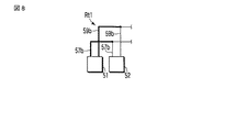
すなわち、インク流路が各インクジェットヘッド毎に分離しておらず、複数のインクジェットヘッドに共有される共通インク流路と分岐点とを持っている場合は、共通インク流路は分岐先の独立インク流路の各々の流路抵抗の比と同じ比率に按分利用されていると考えることができるので、共通インク流路を分岐先の各々の流路抵抗の比と同じ比率の並列抵抗として按分してインクジェットヘッド毎の流路抵抗を計算する。 That is, if the ink flow path is not separated for each inkjet head and has a common ink flow path and a branch point shared by a plurality of inkjet heads, the common ink flow path is the independent ink at the branch destination. Since it can be considered that the ratio of the flow resistance of each flow path is proportionally used, the common ink flow path is divided as a parallel resistance having the same ratio as the flow resistance ratio of each branch destination. To calculate the channel resistance for each inkjet head.
ここで、共通インク流路を並列抵抗に按分する仕方を図18に示す等価回路図を用いて説明する。 Here, how to distribute the common ink flow path to the parallel resistance will be described with reference to an equivalent circuit diagram shown in FIG.
インクジェットヘッド201のノズルより上流側分岐点までの流路抵抗をR3とし、インクジェットヘッド201のノズルより下流側分岐点までの流路抵抗をR4とし、インクジェットヘッド202のノズルより上流側分岐点までの流路抵抗をR5とし、インクジェットヘッド202のノズルより下流側分岐点までの流路抵抗をR6とし、上流側の共通インク流路の流路抵抗をR7とし、下流側の共通インク流路の流路抵抗をR8としたとき、上記流路抵抗R7を互いに並列接続された流路抵抗R71と流路抵抗R72とに按分して考え、上記流路抵抗R8を互いに並列接続された流路抵抗R81と流路抵抗R82とに按分して考える。
The flow resistance from the nozzle of the
按分の仕方は、
“R71:R72=R81:R82=(R3+R4):(R5+R6)”
“1/R7=1/R71+1/R72”
“1/R8=1/R81+1/R82”
の条件が成立するようにすればよい。このとき、“R71:R81=R72:R82=R7:R8”である。
How to apportion
“R71: R72 = R81: R82 = (R3 + R4) :( R5 + R6)”
“1 / R7 = 1 / R71 + 1 / R72”
“1 / R8 = 1 / R81 + 1 / R82”
This condition should be satisfied. At this time, “R71: R81 = R72: R82 = R7: R8”.
なお、按分後のインクジェットヘッド201のノズルより上流の流路抵抗は“R71+R3”、インクジェットヘッド201のノズルより下流の流路抵抗は“R81+R4”、インクジェットヘッド202のノズルより上流の流路抵抗は“R72+R5”、インクジェットヘッド202のノズルより下流の流路抵抗は“R82+R6”とする。
The flow resistance upstream of the nozzles of the
ここで、“R3:R4=R5:R6=R7:R8=1:r”となるように各部の流路抵抗を調整しておくと扱い易い。 Here, it is easy to handle if the flow resistance of each part is adjusted so that “R3: R4 = R5: R6 = R7: R8 = 1: r”.
このとき、“(R71+R3):(R81+R4)=(R72+R5):(R82+R6)=1:r”となる。すなわち、独立インク流路および共通インク流路の各々において上流側の流路抵抗と下流側の流路抵抗との比を“1:r”に揃えておけば、実際に流路抵抗R71,R72,R81,R82を計算しなくても、ノズルから見た上流側の流路抵抗と下流側の流路抵抗の比は“1:r”であると言うことができ、第5の実施形態でそのようになっている。 At this time, “(R71 + R3) :( R81 + R4) = (R72 + R5) :( R82 + R6) = 1: r”. In other words, if the ratio of the upstream flow path resistance to the downstream flow path resistance is set to “1: r” in each of the independent ink flow path and the common ink flow path, the flow path resistances R71 and R72 are actually set. , R81, R82 without calculating the ratio of the upstream-side flow resistance and the downstream-side flow resistance viewed from the nozzle can be said to be “1: r”. In the fifth embodiment, It is like that.
なお、この発明は、上記各実施形態に限定されるものではなく、要旨を変えない範囲で種々変形実施可能であり、また複数の実施形態を組合わせる構成としてもよい。 The present invention is not limited to the above-described embodiments, and various modifications can be made without departing from the scope of the present invention, and a plurality of embodiments may be combined.
1…ノズル、2…オリフィスプレート、3…圧力室、4…インク、4a…インク滴、5…ヘッド内流路、6…アクチュエータ、10…CPU、11…インクジェットヘッド、12…第1インクタンク、13a…第1インク流路、13b…第2インク流路、13c…第3インク流路、14…第2インクタンク、15…メインタンク、16…第1ポンプ、17…第2ポンプ、18…フィルタ、19…第1液面センサ、20…第2液面センサ
DESCRIPTION OF
Claims (25)
前記インクによって前記ノズルの開口高さ位置の大気圧の静止インクを基準とする、「単位体積当たりのエネルギー」P1(Pa)が生じるようにインクの単位体積当たりのエネルギーを調整する第1圧力源と、
前記インクによって前記ノズルの開口高さ位置の大気圧の静止インクを基準とする、「単位体積当たりのエネルギー」P2(Pa) が生じるようにインクの単位体積当たりのエネルギーを調整する第2圧力源と、
制御手段と、
を備え、
前記第1圧力源、前記圧力室、および前記第2圧力源は、第1及び第2流路によって順次に接続され、
前記第1及び第2流路から前記ノズルへ分岐する分岐点から前記第1圧力源に至る流路の流路抵抗と、前記分岐点から前記第2圧力源に至る流路の流路抵抗との比を“1:r”としたとき、前記制御手段は、少なくとも前記ノズルからのインク吐出時に、前記「単位体積当たりのエネルギー」P2(Pa)を、前記ノズルの開口近傍におけるインクの適正圧力Pnを用いた“P2={(1+r)×Pn}−(r×P1)”の関係に保持し、適正圧力Pnは0(大気圧)以下である、
ことを特徴とするインクジェット装置。 A pressure chamber communicating with the nozzle, and at least one ink jet head that ejects ink communicating with the pressure chamber from the nozzle;
The first pressure source that adjusts the energy per unit volume of the ink so that the “energy per unit volume” P1 (Pa) is generated by the ink with reference to the stationary ink at the atmospheric pressure at the opening height of the nozzle. When,
A second pressure source that adjusts the energy per unit volume of the ink so that the “energy per unit volume” P2 (Pa) is generated by the ink with reference to the stationary ink at the atmospheric pressure at the nozzle opening height position. When,
Control means;
With
The first pressure source, the pressure chamber, and the second pressure source are sequentially connected by first and second flow paths,
A flow path resistance of a flow path from a branch point that branches from the first and second flow paths to the nozzle to the first pressure source, and a flow path resistance of a flow path from the branch point to the second pressure source. When the ratio of the ratio is “1: r”, the control means uses the “energy per unit volume” P2 (Pa) at least when ink is ejected from the nozzle as the appropriate pressure of ink in the vicinity of the nozzle opening. Maintaining the relationship of “P2 = {(1 + r) × Pn} − (r × P1)” using Pn, the appropriate pressure Pn is 0 (atmospheric pressure) or less.
An inkjet apparatus characterized by that.
前記各分岐点から前記第1インク接続ポートまでの各流路抵抗と、前記各分岐点から前記第2インク接続ポートまでの各流路抵抗との各比は、互いに等しい、
ことを特徴とする請求項1に記載のインクジェット装置。 The inkjet head has a plurality of the nozzles, has a first ink connection port on a side close to the first pressure source from each branch point where the nozzle branches from the first and second flow paths, A second ink connection port on the side closer to the second pressure source from the branch point;
Each ratio of each flow path resistance from each branch point to the first ink connection port and each flow path resistance from each branch point to the second ink connection port is equal to each other.
The inkjet apparatus according to claim 1.
前記第1及び第2流路から各インクジェットヘッドのノズルへ分岐する各分岐点から前記第1圧力源に至る各流路抵抗と、前記各分岐点から前記第2圧力源に至る各流路抵抗との各比は、互いに等しく、“1:r”である、
ことを特徴とする請求項1に記載のインクジェット装置。 The inkjet head is plural,
Each flow path resistance from each branch point branching from the first and second flow paths to the nozzles of each inkjet head to the first pressure source, and each flow path resistance from each branch point to the second pressure source Are equal to each other and are “1: r”.
The inkjet apparatus according to claim 1.
前記第1インクタンクは、第1インクポートおよび第2インクポートを有し、
前記第2圧力源は、第2インク液面を有する第2インクタンクにあって、
前記第2インクタンクは、第3インクポートおよび第4インクポートを有し、
前記第1インクポートおよび前記第3インクポートは、前記第1及び第2流路に接続されており、
前記第2インクポートおよび前記第4インクポートは、第1インク送り手段に接続されており、
前記第1インク送り手段は、前記第1インク液面の高さを検知する第1液面センサの検知結果、および前記第2インク液面の高さを検知する第2液面センサの検知結果が、各々、所定高さとなるように、前記第2インクポートおよび前記第4インクポートから前記インクを出入りさせ、
前記第1インク液面の圧力をPi1(Pa)、前記第2インク液面の圧力をPi2(Pa)、前記ノズルの開口高さ位置を基準とする前記第1インク液面の高さをh1(m)、前記ノズルの開口高さ位置を基準とする前記第2インク液面の高さをh2(m)、前記インクの密度をρ(kg/m3)、重力加速度をg(m/s2)としたとき、前記「単位体積当たりのエネルギー」P1および前記「単位体積当たりのエネルギー」P2は、“P1=Pi1+ρ・g・h1”、 “P2=Pi2+ρ・g・h2”である、
ことを特徴とする請求項1に記載のインクジェット装置。 The first pressure source is in a first ink tank having a first ink level,
The first ink tank has a first ink port and a second ink port;
The second pressure source is in a second ink tank having a second ink level,
The second ink tank has a third ink port and a fourth ink port,
The first ink port and the third ink port are connected to the first and second flow paths,
The second ink port and the fourth ink port are connected to first ink feeding means,
The first ink feeding means includes a detection result of a first liquid level sensor that detects the height of the first ink liquid level, and a detection result of a second liquid level sensor that detects the height of the second ink liquid level. Are made to enter and leave the ink from the second ink port and the fourth ink port so that each has a predetermined height,
The pressure of the first ink liquid surface is Pi1 (Pa), the pressure of the second ink liquid surface is Pi2 (Pa), and the height of the first ink liquid surface with reference to the opening height position of the nozzle is h1. (m), the height of the second ink surface relative to the nozzle opening height position is h2 (m), the density of the ink is ρ (kg / m 3 ), and the gravitational acceleration is g (m / m). s 2 ), the “energy per unit volume” P1 and the “energy per unit volume” P2 are “P1 = Pi1 + ρ · g · h1” and “P2 = Pi2 + ρ · g · h2”.
The inkjet apparatus according to claim 1.
前記第2インク液面は、圧力調整された第2気圧源に連通している、
ことを特徴とする請求項8に記載のインクジェット装置。 The first ink liquid level communicates with a pressure-adjusted first atmospheric pressure source,
The second ink liquid level communicates with a pressure-adjusted second atmospheric pressure source;
The ink jet apparatus according to claim 8.
前記第1気圧源の体積と前記第2気圧源の体積との比は、r:1である、
ことを特徴とする請求項9に記載のインクジェット装置。 A pump capable of moving gas between the first atmospheric pressure source and the second atmospheric pressure source;
The ratio of the volume of the first atmospheric pressure source to the volume of the second atmospheric pressure source is r: 1.
The inkjet apparatus according to claim 9.
前記第1インクタンクと、前記第1及び第2流路、前記第2インクタンク、前記第2ポンプは、インクを循環可能な循環路を構成している、
ことを特徴とする請求項8に記載のインクジェット装置。 The first ink feeding means has a second pump capable of moving ink between the first ink tank and the second ink tank,
The first ink tank, the first and second flow paths, the second ink tank, and the second pump constitute a circulation path capable of circulating ink.
The ink jet apparatus according to claim 8.
前記循環路と前記メインタンクとの間でインクを授受する第2インク送り手段と、
をさらに備え、
前記第2ポンプは、前記第1液面センサの検知結果が所定高さとなるように制御され、
前記第2インク送り手段は、前記第2液面センサの検知結果が所定高さとなるように制御される、
ことを特徴とする請求項11に記載のインクジェット装置。 A main tank containing ink,
A second ink feeding means for transferring ink between the circulation path and the main tank;
Further comprising
The second pump is controlled so that a detection result of the first liquid level sensor becomes a predetermined height,
The second ink feeding means is controlled so that a detection result of the second liquid level sensor becomes a predetermined height.
The inkjet apparatus according to claim 11.
前記第2インク送り手段は、前記メインタンクに連通して前記第2インクタンクに接続される第4インク流路、前記第2インクタンクと前記メインタンクとを導通又は遮断制御するための第1バルブ、前記メインタンクに連通して前記第1インクタンクに接続される第5インク流路、および前記第1インクタンクと前記メインタンクとを導通又は遮断制御するための第2バルブにより構成され、前記第2液面センサの検知結果が所定高さよりも低い間は前記第1バルブを開き、前記第2液面センサの検知結果が所定高さよりも高い間は前記第2バルブを開く、
ことを特徴とする請求項12に記載のインクジェット装置。 “Energy per unit volume” P3 (Pa) of the ink in the main tank with reference to the static ink at atmospheric pressure at the nozzle opening height position, the “energy per unit volume” P1, and the “unit volume” The hit energy “P2” has a relationship of “P1>P3> P2”,
The second ink feeding means communicates with the main tank and is connected to the second ink tank, and a first ink passage is connected to the second ink tank, and a first ink for conducting or blocking control between the second ink tank and the main tank. A valve, a fifth ink flow path that communicates with the main tank and is connected to the first ink tank, and a second valve for conducting or blocking control between the first ink tank and the main tank, While the detection result of the second liquid level sensor is lower than a predetermined height, the first valve is opened, and while the detection result of the second liquid level sensor is higher than a predetermined height, the second valve is opened.
The inkjet apparatus according to claim 12.
インクが収容されたメインタンクと、
前記第1インクタンクと前記メインタンクとの間でインクを移動可能な第3インク送り手段と、
前記第2インクタンクと前記メインタンクとの間でインクを移動可能な第4インク送り手段と、
を有し、
前記第3インク送り手段は、前記第1液面センサの検知結果が所定高さとなるように制御する。
前記第4インク送り手段は、前記第2液面センサの検知結果が所定高さとなるように制御する。
ことを特徴とする請求項8に記載のインクジェット装置。 The first ink feeding means is
A main tank containing ink,
A third ink feeding means capable of moving ink between the first ink tank and the main tank;
A fourth ink feeding means capable of moving ink between the second ink tank and the main tank;
Have
The third ink feeding means controls the detection result of the first liquid level sensor to be a predetermined height.
The fourth ink feeding means controls the detection result of the second liquid level sensor to be a predetermined height.
The ink jet apparatus according to claim 8.
前記第1インク送り手段は、前記第1液面センサが検知する液面高さ位置が、前記ノズルの開口高さ位置を基準にして“P1/(ρ・g)”となるように前記第2インクポートからインクを出入りさせる、
ことを特徴とする請求項8に記載のインクジェット装置。 The pressure of the first ink liquid level is atmospheric pressure,
The first ink feeding means is configured so that a liquid level height detected by the first liquid level sensor is “P1 / (ρ · g)” with reference to an opening height position of the nozzle. 2 Make ink enter and exit from the ink port,
The ink jet apparatus according to claim 8.
前記第1インク送り手段は、前記第2液面センサが検知する液面高さ位置が、前記ノズルの開口高さ位置を基準にして“P2/(ρ・g)”となるように、前記第4インクポートからインクを出入りさせる、
ことを特徴とする請求項18に記載のインクジェット装置。 The pressure of the second ink liquid level is atmospheric pressure,
The first ink feeding means is configured so that the liquid level height detected by the second liquid level sensor is “P2 / (ρ · g)” with reference to the opening height position of the nozzle. Let ink go in and out from the 4th ink port,
The inkjet apparatus according to claim 18.
前記第1インクタンクおよび前記第2インクタンクは、前記ラジエータとともに、当該装置が外気と接する、当該装置の端部に配置される、
ことを特徴とする請求項8に記載のインクジェット装置。 It is further equipped with a radiator that can exchange heat with the outside air,
The first ink tank and the second ink tank, together with the radiator, are disposed at an end portion of the device where the device is in contact with outside air.
The ink jet apparatus according to claim 8.
前記第1インクタンクから上方にインクを供給するとともに、そのインク内の気泡がインクとともに上昇できる太さの第1供給管と、
前記第1供給管の上方に水平に配置され、前記第1供給管からのインクを水平方向に供給するとともに、そのインク内の気泡がインクとともに移動できる断面高さを有する上下に扁平な第2供給管と、
前記第2供給管から前記インクジェットヘッドにインクを供給し、そのインク内の気泡がインクとともに降下できる太さの第3供給管と、
をさらに備えていることを特徴とする請求項8に記載のインクジェット装置。 The inkjet head is disposed obliquely above the first ink tank,
A first supply pipe having a thickness capable of supplying ink upward from the first ink tank and allowing bubbles in the ink to rise together with the ink;
A second flat, which is horizontally disposed above the first supply pipe, supplies the ink from the first supply pipe in the horizontal direction, and has a cross-sectional height that allows bubbles in the ink to move together with the ink. A supply pipe;
A third supply pipe having a thickness capable of supplying ink from the second supply pipe to the inkjet head and allowing bubbles in the ink to descend together with the ink;
The inkjet apparatus according to claim 8, further comprising:
この減速機構は、前記第1インクポートおよび前記第2インクポートのうち、インクが流入する側のインクポートに設けられている、
ことを特徴とする請求項8に記載のインクジェット装置。 A further reduction mechanism that decelerates the ink flow rate;
The deceleration mechanism is provided in an ink port on the ink inflow side of the first ink port and the second ink port.
The ink jet apparatus according to claim 8.
前記分離壁の上縁は前記インクが流入する側のインクポートの開口部周長よりも長く、
前記減速機構は、前記分離壁の上縁から、他のインクポートが設けられている領域に向かってインクを溢れ出させる、
ことを特徴とする請求項22に記載のインクジェット装置。 The speed reduction mechanism includes a separation wall that separates an area where the ink port on the ink inflow side in the first ink tank is provided from an area where other ink ports are provided,
The upper edge of the separation wall is longer than the circumference of the opening of the ink port on the side into which the ink flows,
The deceleration mechanism causes ink to overflow from the upper edge of the separation wall toward a region where another ink port is provided.
The inkjet apparatus according to claim 22.
前記インクによって前記ノズルの開口高さ位置の大気圧の静止インクを基準とする「単位体積当たりのエネルギー」P1(Pa)が生じるようにインクの単位体積当たりのエネルギーを調整する第1圧力源と、
前記インクによって前記ノズルの開口高さ位置の大気圧の静止インクを基準とする「単位体積当たりのエネルギー」P2(Pa) が生じるようにインクの単位体積当たりのエネルギーを調整する第2圧力源と、
を備え、
前記第1圧力源、前記圧力室、および前記第2圧力源は、第1及び第2流路によって順次に接続されたインクジェット装置において、
前記第1及び第2流路から前記ノズルへ分岐する分岐点から前記第1圧力源に至る流路の流路抵抗と、前記分岐点から前記第2圧力源に至る流路の流路抵抗との比を“1:r”としたとき、少なくとも前記ノズルからのインク吐出時に、前記「単位体積当たりのエネルギー」P2(Pa)を、前記ノズルの開口近傍におけるインクの適正圧力Pnを用いた“P2={(1+r)×Pn}−(r×P1)”の関係に保持し、適正圧力Pnは0(大気圧)以下である、ことを特徴とするインクジェット装置の制御方法。 A pressure chamber that communicates with the nozzle, and at least one inkjet head that ejects ink from the nozzle that communicates with the pressure chamber;
A first pressure source that adjusts the energy per unit volume of the ink so that the “energy per unit volume” P1 (Pa) is generated by the ink based on the stationary ink at the atmospheric pressure at the opening height of the nozzle. ,
A second pressure source that adjusts the energy per unit volume of the ink so that the ink generates “energy per unit volume” P2 (Pa) based on the stationary ink at the atmospheric pressure at the opening height of the nozzle. ,
Equipped with a,
In the inkjet apparatus in which the first pressure source, the pressure chamber, and the second pressure source are sequentially connected by the first and second flow paths ,
A flow path resistance of a flow path from a branch point that branches from the first and second flow paths to the nozzle to the first pressure source, and a flow path resistance of a flow path from the branch point to the second pressure source. When the ratio of “1: r” is set to “1: r”, at least when the ink is ejected from the nozzle, the “energy per unit volume” P2 (Pa) is used as the appropriate pressure Pn of the ink in the vicinity of the nozzle opening. A control method for an ink jet apparatus, wherein the relationship P2 = {(1 + r) × Pn} − (r × P1) ″ is maintained, and the appropriate pressure Pn is 0 (atmospheric pressure) or less .
前記インクによって前記ノズルの開口高さ位置の大気圧の静止インクを基準とする「単位体積当たりのエネルギー」P1(Pa) が生じるようにインクの単位体積当たりのエネルギーを調整する第1圧力源と、
前記インクによって前記ノズルの開口高さ位置の大気圧の静止インクを基準とする「単位体積当たりのエネルギー」P2(Pa) が生じるように単位体積当たりのエネルギーを調整する第2圧力源と、
制御手段と、
前記第1圧力源と前記インク貯留部とを接続する第1流路と、
前記インク貯留部と前記第2圧力源とを接続する第2流路と、
を備え、
前記第1流路の流路抵抗と前記第2流路の流路抵抗との比を“1:r”としたとき、前記制御手段は、少なくとも前記ノズルからのインク吐出時に、前記「単位体積当たりのエネルギー」P2(Pa)を、前記ノズルの開口近傍におけるインクの適正圧力Pnを用いた“P2={(1+r)×Pn}−(r×P1)”の関係に保持し、適正圧力Pnは0(大気圧)以下である、
ことを特徴とするインクジェット装置。 A pressure chamber communicating with the nozzle and an ink reservoir communicating with the pressure chamber, and at least one inkjet head that ejects ink from the nozzle communicating with the ink reservoir and the pressure chamber;
A first pressure source that adjusts the energy per unit volume of the ink so that the “energy per unit volume” P1 (Pa) is generated by the ink based on the stationary ink at atmospheric pressure at the opening height of the nozzle. ,
A second pressure source that adjusts energy per unit volume so that an “energy per unit volume” P2 (Pa) is generated by the ink based on a stationary ink of atmospheric pressure at the nozzle opening height position;
Control means;
A first flow path connecting the first pressure source and the ink reservoir;
A second flow path connecting the ink reservoir and the second pressure source;
With
Wherein the ratio of the flow resistance of the flow resistance and the second flow path of the first flow path: when the "1 r", said control means, when ink ejection from at least the nozzle, the "unit volume The hit energy “P2 (Pa)” is maintained in the relationship of “P2 = {(1 + r) × Pn} − (r × P1)” using the appropriate pressure Pn of the ink in the vicinity of the nozzle opening , and the appropriate pressure Pn Is below 0 (atmospheric pressure) ,
An inkjet apparatus characterized by that.
Priority Applications (1)
| Application Number | Priority Date | Filing Date | Title |
|---|---|---|---|
| JP2007105265A JP5728148B2 (en) | 2006-04-27 | 2007-04-12 | Ink jet apparatus and control method thereof |
Applications Claiming Priority (3)
| Application Number | Priority Date | Filing Date | Title |
|---|---|---|---|
| JP2006123927 | 2006-04-27 | ||
| JP2006123927 | 2006-04-27 | ||
| JP2007105265A JP5728148B2 (en) | 2006-04-27 | 2007-04-12 | Ink jet apparatus and control method thereof |
Related Child Applications (3)
| Application Number | Title | Priority Date | Filing Date |
|---|---|---|---|
| JP2011217838A Division JP5380511B2 (en) | 2006-04-27 | 2011-09-30 | Ink jet apparatus and control method thereof |
| JP2011217837A Division JP2012001001A (en) | 2006-04-27 | 2011-09-30 | Ink tank for ink jet unit and ink jet unit |
| JP2014243372A Division JP6047543B2 (en) | 2006-04-27 | 2014-12-01 | Inkjet device |
Publications (3)
| Publication Number | Publication Date |
|---|---|
| JP2007313884A JP2007313884A (en) | 2007-12-06 |
| JP2007313884A5 JP2007313884A5 (en) | 2010-05-27 |
| JP5728148B2 true JP5728148B2 (en) | 2015-06-03 |
Family
ID=38848174
Family Applications (1)
| Application Number | Title | Priority Date | Filing Date |
|---|---|---|---|
| JP2007105265A Active JP5728148B2 (en) | 2006-04-27 | 2007-04-12 | Ink jet apparatus and control method thereof |
Country Status (1)
| Country | Link |
|---|---|
| JP (1) | JP5728148B2 (en) |
Cited By (1)
| Publication number | Priority date | Publication date | Assignee | Title |
|---|---|---|---|---|
| WO2021140646A1 (en) | 2020-01-10 | 2021-07-15 | コニカミノルタ株式会社 | Inkjet recording device and manufacturing method for same |
Families Citing this family (39)
| Publication number | Priority date | Publication date | Assignee | Title |
|---|---|---|---|---|
| JP4108725B1 (en) * | 2007-03-02 | 2008-06-25 | シャープ株式会社 | Recording apparatus and recording method |
| JP5222564B2 (en) * | 2008-01-04 | 2013-06-26 | 理想科学工業株式会社 | Ink circulation confirmation method and ink filling method |
| JP5154258B2 (en) * | 2008-02-21 | 2013-02-27 | 理想科学工業株式会社 | Inkjet printer |
| JP5009229B2 (en) * | 2008-05-22 | 2012-08-22 | 富士フイルム株式会社 | Inkjet recording device |
| JP5084610B2 (en) * | 2008-05-27 | 2012-11-28 | 大日本スクリーン製造株式会社 | Printing apparatus and printing method |
| JP5084609B2 (en) | 2008-05-27 | 2012-11-28 | 大日本スクリーン製造株式会社 | Head unit and printing apparatus |
| JP5102108B2 (en) * | 2008-05-27 | 2012-12-19 | 大日本スクリーン製造株式会社 | Inkjet head, head unit, and printing apparatus |
| JP4535181B2 (en) * | 2008-08-26 | 2010-09-01 | ブラザー工業株式会社 | Control method for liquid ejection device and liquid ejection device |
| JP5292037B2 (en) * | 2008-09-25 | 2013-09-18 | 理想科学工業株式会社 | Inkjet recording device |
| JP5127649B2 (en) * | 2008-09-29 | 2013-01-23 | 富士フイルム株式会社 | Liquid ejection device |
| JP5394792B2 (en) * | 2009-03-27 | 2014-01-22 | 大日本スクリーン製造株式会社 | Printing device |
| US20120033019A1 (en) * | 2010-08-09 | 2012-02-09 | Toshiba Tec Kabushiki Kaisha | Inkjet recording apparatus and inkjet recording method |
| US8876243B2 (en) * | 2010-09-13 | 2014-11-04 | Toshiba Tec Kabushiki Kaisha | Inkjet recording device and inkjet recording method |
| JP5400736B2 (en) * | 2010-09-14 | 2014-01-29 | 東芝テック株式会社 | Inkjet device |
| JP5723610B2 (en) * | 2011-01-26 | 2015-05-27 | 理想科学工業株式会社 | Inkjet recording device |
| JP5699014B2 (en) * | 2011-03-29 | 2015-04-08 | 京セラドキュメントソリューションズ株式会社 | Inkjet recording device |
| JP5518814B2 (en) * | 2011-09-08 | 2014-06-11 | 東芝テック株式会社 | Printer and printer control method |
| JP5615307B2 (en) | 2012-02-14 | 2014-10-29 | 富士フイルム株式会社 | Droplet discharge device |
| CN104220263B (en) * | 2012-03-14 | 2016-03-02 | 柯尼卡美能达株式会社 | The maintaining method of image processing system and record head |
| US8764176B2 (en) | 2012-04-26 | 2014-07-01 | Seiko Epson Corporation | Liquid ejecting apparatus |
| JP5784660B2 (en) * | 2013-03-11 | 2015-09-24 | 東芝テック株式会社 | Inkjet device |
| JP6274207B2 (en) * | 2013-05-20 | 2018-02-07 | コニカミノルタ株式会社 | Inkjet recording apparatus and recording head maintenance method |
| JP6228795B2 (en) * | 2013-09-26 | 2017-11-08 | エスアイアイ・プリンテック株式会社 | Liquid ejecting unit and liquid ejecting apparatus |
| JP6280742B2 (en) | 2013-12-27 | 2018-02-14 | 東芝テック株式会社 | Liquid circulation device, liquid discharge recording device, and liquid circulation method |
| JP6371072B2 (en) * | 2014-02-21 | 2018-08-08 | セーレン株式会社 | Ink supply system for ink jet printer and ink pressure control method in the system |
| JP6322101B2 (en) * | 2014-09-16 | 2018-05-09 | 理想科学工業株式会社 | Inkjet printing device |
| JP6367065B2 (en) * | 2014-09-22 | 2018-08-01 | 理想科学工業株式会社 | Inkjet printing device |
| JP6435149B2 (en) * | 2014-09-29 | 2018-12-05 | 理想科学工業株式会社 | Inkjet printing device |
| JP6286387B2 (en) * | 2015-04-27 | 2018-02-28 | 株式会社東芝 | Inkjet device |
| JP6322160B2 (en) * | 2015-06-11 | 2018-05-09 | 株式会社東芝 | Inkjet printer |
| JP6838927B2 (en) * | 2015-10-16 | 2021-03-03 | 芝浦メカトロニクス株式会社 | Tablet printing device and tablet printing method |
| JP6135744B2 (en) * | 2015-11-17 | 2017-05-31 | セイコーエプソン株式会社 | Liquid ejection device |
| JP6691768B2 (en) * | 2015-12-17 | 2020-05-13 | 理想科学工業株式会社 | Inkjet printer |
| JP7034586B2 (en) | 2016-01-08 | 2022-03-14 | キヤノン株式会社 | Liquid discharge head and liquid discharge method |
| JP6286456B2 (en) * | 2016-01-28 | 2018-02-28 | 株式会社東芝 | Inkjet device |
| JP6928036B2 (en) * | 2017-06-21 | 2021-09-01 | 東芝テック株式会社 | Liquid circulation device and liquid discharge recording device |
| JP6557289B2 (en) * | 2017-06-21 | 2019-08-07 | 東芝テック株式会社 | Liquid circulation device and liquid discharge recording device |
| CN107696702A (en) * | 2017-10-28 | 2018-02-16 | 青岛三皆益喷码技术有限公司 | A kind of inside and outside automatic flushing device for ink jet numbering machine |
| KR102645832B1 (en) | 2021-08-06 | 2024-03-08 | 세메스 주식회사 | Apparatus for jetting droplet |
Family Cites Families (8)
| Publication number | Priority date | Publication date | Assignee | Title |
|---|---|---|---|---|
| JP3419220B2 (en) * | 1996-10-15 | 2003-06-23 | セイコーエプソン株式会社 | Ink jet recording device |
| JP3794165B2 (en) * | 1998-06-01 | 2006-07-05 | ブラザー工業株式会社 | Inkjet printer |
| GB9828476D0 (en) * | 1998-12-24 | 1999-02-17 | Xaar Technology Ltd | Apparatus for depositing droplets of fluid |
| JP2001219580A (en) * | 2000-02-07 | 2001-08-14 | Hitachi Ltd | Recording head and ink-jet recording apparatus using the same |
| JP2003276189A (en) * | 2002-03-20 | 2003-09-30 | Fuji Photo Film Co Ltd | Liquid drop ejector and ink jet recording head |
| WO2006030235A2 (en) * | 2004-09-18 | 2006-03-23 | Xaar Technology Limited | Fluid supply method and apparatus |
| JP4236648B2 (en) * | 2005-07-19 | 2009-03-11 | 芝浦メカトロニクス株式会社 | Solution coating apparatus and coating method |
| JP4108725B1 (en) * | 2007-03-02 | 2008-06-25 | シャープ株式会社 | Recording apparatus and recording method |
-
2007
- 2007-04-12 JP JP2007105265A patent/JP5728148B2/en active Active
Cited By (1)
| Publication number | Priority date | Publication date | Assignee | Title |
|---|---|---|---|---|
| WO2021140646A1 (en) | 2020-01-10 | 2021-07-15 | コニカミノルタ株式会社 | Inkjet recording device and manufacturing method for same |
Also Published As
| Publication number | Publication date |
|---|---|
| JP2007313884A (en) | 2007-12-06 |
Similar Documents
| Publication | Publication Date | Title |
|---|---|---|
| JP6047543B2 (en) | Inkjet device | |
| JP5728148B2 (en) | Ink jet apparatus and control method thereof | |
| JP5486191B2 (en) | Inkjet printer | |
| JP5031544B2 (en) | Inkjet recording apparatus, ink supply mechanism, and ink supply method | |
| JP5085249B2 (en) | Ink supply mechanism | |
| JP5031545B2 (en) | Inkjet recording apparatus, ink supply mechanism, and inkjet recording method | |
| EP2769847B1 (en) | Ink supply system for ink jet printers | |
| US8398217B2 (en) | Inkjet printing device | |
| JP5586539B2 (en) | Inkjet recording apparatus and inkjet recording method | |
| JP2010173209A (en) | Inkjet printer and ink circulation method | |
| JP2010012637A (en) | Image formation system | |
| JP2016068431A (en) | Ink jet printer | |
| JP6286456B2 (en) | Inkjet device | |
| JP6286387B2 (en) | Inkjet device | |
| JP5418423B2 (en) | Inkjet recording device | |
| JP2013028041A (en) | Circulation type inkjet head apparatus |
Legal Events
| Date | Code | Title | Description |
|---|---|---|---|
| A521 | Written amendment |
Free format text: JAPANESE INTERMEDIATE CODE: A523 Effective date: 20100412 |
|
| A621 | Written request for application examination |
Free format text: JAPANESE INTERMEDIATE CODE: A621 Effective date: 20100412 |
|
| A977 | Report on retrieval |
Free format text: JAPANESE INTERMEDIATE CODE: A971007 Effective date: 20120323 |
|
| RD04 | Notification of resignation of power of attorney |
Free format text: JAPANESE INTERMEDIATE CODE: A7424 Effective date: 20120529 |
|
| A131 | Notification of reasons for refusal |
Free format text: JAPANESE INTERMEDIATE CODE: A131 Effective date: 20121002 |
|
| A131 | Notification of reasons for refusal |
Free format text: JAPANESE INTERMEDIATE CODE: A131 Effective date: 20130903 |
|
| A521 | Written amendment |
Free format text: JAPANESE INTERMEDIATE CODE: A523 Effective date: 20131105 |
|
| RD04 | Notification of resignation of power of attorney |
Free format text: JAPANESE INTERMEDIATE CODE: A7424 Effective date: 20131212 |
|
| RD04 | Notification of resignation of power of attorney |
Free format text: JAPANESE INTERMEDIATE CODE: A7424 Effective date: 20140224 |
|
| A02 | Decision of refusal |
Free format text: JAPANESE INTERMEDIATE CODE: A02 Effective date: 20140902 |
|
| A521 | Written amendment |
Free format text: JAPANESE INTERMEDIATE CODE: A523 Effective date: 20141201 |
|
| A911 | Transfer of reconsideration by examiner before appeal (zenchi) |
Free format text: JAPANESE INTERMEDIATE CODE: A911 Effective date: 20141208 |
|
| TRDD | Decision of grant or rejection written | ||
| A01 | Written decision to grant a patent or to grant a registration (utility model) |
Free format text: JAPANESE INTERMEDIATE CODE: A01 Effective date: 20150310 |
|
| A61 | First payment of annual fees (during grant procedure) |
Free format text: JAPANESE INTERMEDIATE CODE: A61 Effective date: 20150406 |
|
| R150 | Certificate of patent (=grant) or registration of utility model |
Ref document number: 5728148 Country of ref document: JP Free format text: JAPANESE INTERMEDIATE CODE: R150 |