JP6838927B2 - Tablet printing device and tablet printing method - Google Patents
Tablet printing device and tablet printing method Download PDFInfo
- Publication number
- JP6838927B2 JP6838927B2 JP2016203965A JP2016203965A JP6838927B2 JP 6838927 B2 JP6838927 B2 JP 6838927B2 JP 2016203965 A JP2016203965 A JP 2016203965A JP 2016203965 A JP2016203965 A JP 2016203965A JP 6838927 B2 JP6838927 B2 JP 6838927B2
- Authority
- JP
- Japan
- Prior art keywords
- ink
- bottle
- discharge
- inkjet head
- printing
- Prior art date
- Legal status (The legal status is an assumption and is not a legal conclusion. Google has not performed a legal analysis and makes no representation as to the accuracy of the status listed.)
- Active
Links
Images


Description
本発明の実施形態は、錠剤印刷装置及び錠剤印刷方法に関する。 Embodiments of the present invention relate to a tablet printing apparatus and a tablet printing method.
錠剤の表面に文字やマークなどを印刷する装置として、インクジェットヘッドを用いる装置が知られている。 A device using an inkjet head is known as a device for printing characters, marks, and the like on the surface of a tablet.
このインクジェットヘッドでは、特許文献1のように、インクジェットヘッドに供給するインクを無駄なく使うために、インクジェットヘッドに供給と排出を設け、インクジェットヘッド内を通過したインクを排出から供給タンクに戻すことが行われている。
In this inkjet head, as in
しかしながら、錠剤印刷においては、衛生上の観点から数時間あるいは一日、あるいは、品種の切り替えやロットの切り替わりのタイミングなどで、印刷装置のメンテナンスとして洗浄が行われる。特に、インクが通過するインクジェットヘッドや配管の洗浄において、特許文献1のような複雑な配管系統では、時間がかかるばかりか、各所のバルブなどの複雑な部品が確実に洗浄されているかどうかの確認は困難である。
However, in tablet printing, cleaning is performed as maintenance of the printing apparatus for several hours or one day from the viewpoint of hygiene, or at the timing of switching varieties or switching lots. In particular, in cleaning the inkjet head and piping through which ink passes, it takes time not only in a complicated piping system as in
また、インクによっては、インク成分の凝集が起こりやすい。このようなインク成分の凝集した凝集体があると、インクジェットヘッド内で流路を狭めたり、インクジェットヘッドの吐出ノズル内に詰まったりして、吐出不良となることがある。 Further, depending on the ink, agglutination of ink components is likely to occur. If there is such an agglomerated aggregate of ink components, the flow path may be narrowed in the inkjet head or the ejection nozzle of the inkjet head may be clogged, resulting in ejection failure.
本発明は、メンテナンスを容易に、確実に行え、錠剤に適切に印刷することのできる錠剤印刷装置及び錠剤印刷方法を提供することにある。 The present invention is to provide a tablet printing apparatus and a tablet printing method capable of easily and surely performing maintenance and appropriately printing on a tablet.
実施形態に係る錠剤印刷装置は、
搬送装置と、
前記搬送装置により搬送される錠剤に対してノズルからインクを吐出することで印刷を行うインクジェットヘッドと、
前記インクジェットヘッドに接続される供給管を介して、前記インクジェットヘッドに供給されるインクを収容するインクボトルと、
前記インクボトルとは別に設けられ、前記インクジェットヘッドに接続される排出管を介して、前記インクジェットヘッドから排出されるインクを収容する排出ボトルと、
前記排出管に設けられた開閉バルブと、
少なくとも前記搬送装置、前記インクジェットヘッド及び前記排出管に設けられた前記開閉バルブの各部の制御を行う制御部とを備え、
前記制御部は、
前記供給管における前記インクボトル側の端面が、前記インクボトルに収容された前記 インク内に位置するように配置される第1の状態、
前記インクジェットヘッドの前記ノズルが形成されるノズル形成面の高さと、前記排出管内のインクの排出ボトル側の端面の高さまたは排出ボトル内におけるインクの液面の高 さと、により形成される排出側の水頭差が、前記インクボトル内における前記インクの液面の高さと、前記ノズル形成面の高さと、により形成される供給側の水頭差より大きく設けられる第2の状態、
前記供給側の水頭差と前記排出側の水頭差が、前記ノズルから外気が吸い込まれてしまう水頭差より小さくなるように、前記排出管内のインクの排出ボトル側の端面の高さが設定される第3の状態、
の全ての状態が同時に維持される状態で、前記開閉バルブを閉から開にするように制御す ることで、前記水頭差だけを用いて前記インクジェットヘッド内の前記インクの前記排出 ボトルへの排出と、前記インクボトルから前記インクジェットヘッドへの前記インクの供 給と、を同時に行うことを特徴とする。The tablet printing apparatus according to the embodiment is
Conveyor and
An inkjet head that prints by ejecting ink from a nozzle on tablets transported by the transfer device.
An ink bottle containing ink supplied to the inkjet head via a supply tube connected to the inkjet head, and an ink bottle.
An discharge bottle provided separately from the ink bottle and accommodating ink discharged from the inkjet head via a discharge pipe connected to the inkjet head.
An on-off valve provided in the discharge pipe and
And at least the conveying device, the control unit controlling each part of the on-off valve provided in the ink jet head and the discharge pipe,
The control unit
A first state in which the end face of the supply pipe on the ink bottle side is arranged so as to be located in the ink contained in the ink bottle.
Emissions formed and the height of the nozzle forming surface of the nozzle of the ink-jet head is formed by a height of the liquid level of the ink in the height of the end face of the discharge bottle side of the ink discharge tube or discharge bottle water head difference of the side is, the the height of the liquid surface of the ink in the ink bottle, the height of the nozzle surface, the second that provided greater than the water head difference between the supply side, which is formed by the state,
Water head difference between the discharge side and the water head difference between the supply side, the so ambient air from the nozzle is less than the water head difference will be drawn, the height of the end face of the discharge bottle side of the ink of the discharge tube is Ru is set Third state,
With all the states of is maintained at the same time, discharge of the off valve in Rukoto be controlled to from the closed to the open, into the discharge bottle of the ink in the ink-jet head by using only the water head difference When, and carrying out the supply of the ink from the ink bottle into the ink jet head, simultaneously.
実施形態に係る錠剤印刷方法は、
搬送される錠剤に、ノズルからインクを吐出するインクジェットヘッドを用いて印刷を行う錠剤印刷方法において、
前記インクジェットヘッドに接続される供給管を介して前記インクをインクボトルから 前記インクジェットヘッドに供給するステップと、
前記インクジェットヘッドにより印刷処理するステップと、
前記印刷処理に基づいて時間を計時するステップと、
この計時した時間が所定時間に達した時に、前記印刷処理を停止し、前記インクジェッ トヘッドから前記インクを、前記インクボトルとは別の排出ボトルに排出するステップと、
前記インクを排出している時間を計時するステップと、
この計時したインクを排出している時間が所定時間に達した時に、前記インクの排出を停止して、前記印刷処理を再開するステップとを備え、
前記インクを排出するステップでは、
前記供給管における前記インクボトル側の端面が、前記インクボトルに収容された前記 インク内に位置するように配置される第1の状態、
前記インクジェットヘッドの、インクの排出側に形成される排出側の水頭差が、インクの供給側に形成される供給側の水頭差より大きく設けられる第2の状態、
前記供給側の水頭差と前記排出側の水頭差が、前記ノズルから外気が吸い込まれてしまう水頭差より小さくなるよう設けられた第3の状態、
の全ての状態が同時に維持される状態で、前記排出管に設けられた開閉バルブを閉から開 にすることで、前記水頭差だけを用いて前記インクジェットヘッド内の前記インクの前記 排出ボトルへの排出と、前記インクボトルから前記インクジェットヘッドへの前記インク の供給と、を同時に行うことを特徴とする。 The tablet printing method according to the embodiment is
In a tablet printing method in which printing is performed on a conveyed tablet using an inkjet head that ejects ink from a nozzle.
To the inkjet headThrough the connected supply pipeThe ink from the ink bottle To the inkjet headWith the steps to supply
The step of printing with the inkjet head and
The step of timing the time based on the printing process and
When the timed time reaches a predetermined time, the printing process is stopped.The ink jet From ToheadThe ink, In a discharge bottle different from the ink bottleSteps to discharge and
The step of timing the time when the ink is discharged and
When the time for discharging the timed ink reaches a predetermined time, the step of stopping the discharge of the ink and restarting the printing process is provided.
In the step of ejecting the ink,
The end face of the supply pipe on the ink bottle side is housed in the ink bottle. The first state, which is located so that it is located in the ink,
Of the inkjet head,The head difference on the discharge side formed on the ink discharge side is provided to be larger than the head difference on the supply side formed on the ink supply side.Second state,
The head difference on the supply side and the head difference on the discharge side are provided so as to be smaller than the head difference in which outside air is sucked from the nozzle.Third state,
The on-off valve provided in the discharge pipe is opened from the closed state while all the states are maintained at the same time. By using only the head difference, the ink in the inkjet head is said to be in the ink. Discharge to the discharge bottle and the ink from the ink bottle to the inkjet head. It is characterized by supplying and performing at the same time...
本発明によれば、メンテナンスを容易に、確実に行え、錠剤に適切に印刷することのできる錠剤印刷装置及び錠剤印刷方法を提供することができる。 According to the present invention, it is possible to provide a tablet printing apparatus and a tablet printing method capable of easily and surely performing maintenance and appropriately printing on a tablet.
以下、本発明の実施形態について図面を参照して詳細に説明する。 Hereinafter, embodiments of the present invention will be described in detail with reference to the drawings.
(第1の実施形態)
図1は、第1の実施形態に係る錠剤印刷装置Sの全体構成を示す正面図である。錠剤印刷装置Sは、印刷対象となる図示しない錠剤を搬送する搬送装置Cと、その搬送装置Cによって搬送される錠剤に対して印刷を行う印刷部Pとを備えている。
(First Embodiment)
FIG. 1 is a front view showing the overall configuration of the tablet printing apparatus S according to the first embodiment. The tablet printing device S includes a transport device C for transporting tablets (not shown) to be printed, and a printing unit P for printing on the tablets transported by the transport device C.
図1に示すように、搬送装置Cは第1の搬送装置1及び第2の搬送装置2により構成されており、それらの第1の搬送装置1及び第2の搬送装置2は上下に配置されている。
As shown in FIG. 1, the transfer device C is composed of a
印刷部Pは第1の印刷部3及び第2の印刷部4により構成されている。
The printing unit P is composed of a
すなわち、第1の搬送装置1の上部に第1の印刷部3が、第2の搬送装置2の上部には第2の印刷部4がそれぞれ組み合わせられて設けられ、全体として錠剤印刷装置Sが構成されている。
That is, the
なお、第1の実施形態においては、第1の搬送装置1と第2の搬送装置2、或いは、第1の印刷部3と第2の印刷部4とは、それぞれ基本的な構成をともに同じくする。
In the first embodiment, the
第1の搬送装置1は、第1のプーリ11と、第2のプーリ12と、無端状の搬送ベルト13と、吸引チャンバ14とを備えている。
The
第1のプーリ11は、図1中の第1の搬送装置1に円形状に示される2つのプーリのうち、左側のプーリである。また、第2のプーリ12は、図1中の前述の2つのプーリのうちの右側のプーリである。
The
搬送ベルト13は、第1のプーリ11と第2のプーリ12とに掛け渡され、端部が設けられない無端状である。従って、搬送ベルト13は、第1のプーリ11と第2のプーリ12とが回転することで回転する。
The transport belt 13 has an endless shape that is hung on the
搬送ベルト13には、印刷対象となる錠剤を、搬送中に保持しておくために、空気を吸引する図示しない吸着孔が設けられている。この吸着孔による吸引によって錠剤を搬送ベルト13の表面に吸着、保持する。そして、この吸引の為に、吸引チャンバ14が、搬送ベルト13の背面に備えられている。 The transport belt 13 is provided with a suction hole (not shown) for sucking air in order to hold the tablet to be printed during transport. The tablets are sucked and held on the surface of the transport belt 13 by suction through the suction holes. A suction chamber 14 is provided on the back surface of the transport belt 13 for this suction.
吸引チャンバ14は、搬送ベルト13の吸着孔に吸引力を付与する。吸引チャンバ14が空気を吸引することによって、吸着孔を介して錠剤は搬送ベルト13に吸着されて保持される。吸引チャンバ14はこのような機能を備えることで、搬送ベルト13の全周のうち、任意の位置において吸着孔に対して吸引力を付与することができるように構成されている。 The suction chamber 14 applies a suction force to the suction holes of the transport belt 13. When the suction chamber 14 sucks air, the tablets are sucked and held by the transport belt 13 through the suction holes. By providing such a function, the suction chamber 14 is configured to be able to apply a suction force to the suction holes at an arbitrary position on the entire circumference of the transport belt 13.
第1の搬送装置1は、上述したような構成を採用しており、第1のプーリ11及び第2のプーリ12は、ともに右回転を行う。そのため、第1の搬送装置1では、搬送ベルト13は、上側の水平領域において実線で示す矢印の方向、すなわち、第1のプーリ11から第2のプーリ12に向けて右向きに進むことになる。
The
第1の搬送装置1の上側には、第1の印刷部3が第1のプーリ11から第2のプーリ12に向けて進む搬送ベルト13の表面に対向する位置に位置付けられて設けられている。従って、第1の印刷部3において錠剤に印刷を行う際には、搬送ベルト13上に錠剤が載置され、第1の印刷部3の下方に搬送される。
On the upper side of the
第1の印刷部3は、錠剤に印刷を行うインクジェット印刷部31と、錠剤の位置(例えば、錠剤が吸着保持された搬送ベルト13上の位置)を検出する位置検出装置32と、錠剤に対して印刷の状態を確認する印刷状態確認装置33とを有している。
The
インクジェット印刷部31は、錠剤の上面に印刷を行う。このインクジェット印刷部31は、例えば、インクジェット方式の印刷ヘッドであるインクジェットヘッド311を備えている。使用されるインクは、上述したような可食性インクである。
The
位置検出装置32は、インクジェット印刷部31が備えるインクジェットヘッド311よりも搬送ベルト13の進行方向上流側に設けられており、搬送ベルト13の表面に保持される錠剤の位置や姿勢(向き、傾き等)を検出する装置である。位置検出装置32は、錠剤を撮影する撮影装置321と、撮影の対象となる錠剤を照らすための照明322とから構成されている。撮影装置321は錠剤を撮影し、その撮影画像を取り込んで制御部5に送信する。すなわち、制御部5は、一例として、第1の印刷部3(位置検出装置32)の構成の一部を担う。制御部5では、撮像画像に基づいて錠剤の位置や姿勢を検出し、この検出結果に基づいて適切な印刷(位置ずれが生じていたら、そのずれを補正等して印刷)を行うべく、インクジェット印刷部31を駆動、或いは、印刷を行わない、といった判断、制御を行う。
The
印刷状態確認装置33は、インクジェットヘッド311よりも搬送ベルト13の進行方向下流側に設けられており、インクジェットヘッド311によって錠剤の上面にされた印刷の状態を確認する装置である。
The print
この印刷状態確認装置33は、錠剤における印刷状態を撮影する撮影装置331と、撮影の対象となる錠剤を照らすための照明332とから構成されている。撮影装置331は錠剤を撮影し、その撮影画像を取り込んで制御部5に送信する。従って、制御部5は、一例として、第1の印刷部3(印刷状態確認装置33)の構成の一部を担う。
The print
制御部5は、撮影装置331によって撮影された画像を基に印刷状態を検出し、印刷の良否を判断する。印刷不良と判断した錠剤については、後述するように、不良品回収ボックスへと移す処理を行う。
The
さらに、第1の搬送装置1の第1のプーリ11の左側には、ホッパ15が設けられている。このホッパ15内には多数の錠剤が収容されており、搬送ベルト13に錠剤を供給可能に構成される。
Further, a hopper 15 is provided on the left side of the
また、搬送装置1の下側には、印刷が終了した錠剤のインクを乾燥させるための乾燥装置16が設けられている。詳述すると、乾燥装置16は、第2のプーリ12から第1のプーリ11へと搬送ベルト13が進む領域(図1中における符号E、F間に位置する、搬送装置1における下側の水平部分)に対向する位置に設けられている。すなわち、乾燥装置16は、搬送ベルト13と対向する位置に設けられており、例えば、錠剤に熱風を吹き付けることで、錠剤に印刷されたインクを乾燥させる。
Further, on the lower side of the
なお、乾燥装置16の配置位置については、錠剤印刷装置Sを構成する他の機構に干渉せず、錠剤に印刷されたインクを乾燥させることができるのであれば、いずれの位置に配置されても良い。 Regarding the placement position of the drying device 16, any position can be used as long as the ink printed on the tablet can be dried without interfering with other mechanisms constituting the tablet printing device S. good.
図1に示すように、錠剤印刷装置Sの上側部分に第1の搬送装置1が配置されており、その下側部分に第2の搬送装置2が配置されている。第2の搬送装置2は、第1の印刷部3により一方の面に印刷された錠剤に対し、自身の上側に設けられている第2の印刷部4により錠剤の他方の面に印刷を行うために錠剤を搬送する装置である。
As shown in FIG. 1, the
第2の搬送装置2は、上述した通り、第1の搬送装置1と基本的に同様である。すなわち、第2の搬送装置2は、第1のプーリ21と、第2のプーリ22と、無端状の搬送ベルト23と、吸引チャンバ24とを備えている。
As described above, the
第1のプーリ21は、図1中の第2の搬送装置2に円形状に示される2つのプーリのうち、右側のプーリである。また、第2のプーリ22は、図1中の前述の2つのプーリのうち、左側のプーリである。
The first pulley 21 is the right pulley of the two pulleys shown in a circular shape on the
搬送ベルト23は、第1のプーリ21と第2のプーリ22とが回転することで、錠剤を搬送する。また、搬送ベルト23には、ベルト面に錠剤を吸着する吸着孔が形成されている。
The
吸引チャンバ24は、搬送ベルト23の吸着孔に吸引力を付与する。吸引チャンバ24が空気を吸引することによって、吸着孔を介して錠剤は搬送ベルト23に吸着されて保持される。吸引チャンバ24はこのような機能を備えることから、吸引チャンバ24は搬送ベルト23の全周のうち、任意の位置において吸着孔に対して吸引力を付与することができるように構成されている。
The suction chamber 24 applies a suction force to the suction holes of the
第2の搬送装置2は、上述したような構成を採用しており、第1のプーリ21及び第2のプーリ22は、ともに左回転を行う。このため、第2の搬送装置2では、搬送ベルト23は、上側の水平領域において実線で示す矢印の方向、すなわち、第1のプーリ21から第2のプーリ22に向けて左向きに進むことになる。
The
第2の搬送装置2の上側には、第2の印刷部4が第1のプーリ21から第2のプーリ22に向けて進む搬送ベルト23の表面に対向する位置に位置付けられて設けられている。従って、第2の印刷部4において錠剤に印刷を行う際には、搬送ベルト23上に錠剤が載置され、第2の印刷部2の下方に搬送される。
A second printing unit 4 is provided on the upper side of the
第2の印刷部4は、錠剤に印刷を行うインクジェット印刷部41と、インクジェット印刷部41が備えるインクジェットヘッド411よりも搬送ベルト23の進行方向上流側に設けられる位置検出装置42と、インクジェットヘッド411よりも搬送ベルト23の進行方向下流側に設けられる印刷状態確認装置43とを有している。
The second printing unit 4 includes an
位置検出装置42は、錠剤を撮影する撮影装置421と、撮影の対象となる錠剤を照らすための照明422とから構成されている。また、印刷状態確認装置43は、錠剤における印刷状態を撮影する撮影装置431と、撮影の対象となる錠剤を照らすための照明432とから構成されている。
The position detection device 42 includes a photographing
なお、ここでのインクジェット印刷部41、位置検出装置42、及び印刷状態確認装置43の役割、働きは、上述した第1の印刷部3の各構成要素と同様である。
The roles and functions of the
また、搬送装置2の下側には、印刷が終了した錠剤のインクを乾燥させるための乾燥装置25が設けられている。詳述すると、乾燥装置25は、搬送ベルト23が第2のプーリ22から第1のプーリ21へと進む領域(図1中における符号I、J間に位置する、搬送装置2における下側の水平部分)に対向する位置に設けられている。
Further, on the lower side of the
なお、乾燥装置25の配置位置については、上述した乾燥装置16の配置位置と同様、錠剤印刷装置Sを構成する他の機構に干渉せず、錠剤に印刷されたインクを乾燥させることができるのであれば、いずれの位置に配置されても良い。
As for the arrangement position of the drying
第2の搬送装置2における乾燥装置25の下流側の位置には、上下両面の表面に対する印刷が終了した錠剤を、印刷の良否に応じて回収するボックス26,27が設けられている。印刷状態確認装置33及び印刷状態確認装置43からの確認結果に基づいて、制御部5が錠剤ごとに印刷の良否を判断する。
Boxes 26 and 27 are provided at positions on the downstream side of the drying
例えば、印刷状態が適切であると判断された場合には、錠剤は搬送ベルト23から良品回収ボックス26へと送られる。一方、印刷状態が不適切であると判断された場合には、錠剤は不良品として搬送ベルト23から不良品回収ボックス27へと送られる。この不良品回収手段の一例としては、搬送ベルト23から良品回収ボックス26へと落下する途中で錠剤に対して空気を吹き付けることによって、不良品回収ボックス27へと収納することが可能である。
For example, if it is determined that the printing condition is appropriate, the tablets are sent from the
(印刷動作)
次に、図1を用いて錠剤印刷装置Sを利用した錠剤への印刷処理を行う印刷動作について、順を追って説明する。
(Printing operation)
Next, a printing operation for performing a printing process on a tablet using the tablet printing device S using FIG. 1 will be described step by step.
まず、ホッパ15に収納されている錠剤が、右向きに回転する第1の搬送装置1の第1のプーリ11に向けて供給される。
First, the tablets stored in the hopper 15 are supplied toward the
図1のような位置でホッパ15から錠剤が供給されるが、吸引チャンバ14から吸着孔に対して吸引力が付与されており、錠剤は落下することなく搬送ベルト13に吸着、保持される。 The tablet is supplied from the hopper 15 at the position as shown in FIG. 1, but a suction force is applied to the suction hole from the suction chamber 14, and the tablet is sucked and held by the transport belt 13 without falling.
錠剤は、吸引チャンバ14によって搬送ベルト13に吸着、保持されたまま搬送され、第1の搬送装置1の上側に設けられている第1の印刷部3によって、その上面に文字や図形等が印刷される。文字や図形等は予め設定されている。
The tablet is conveyed while being attracted to and held by the transfer belt 13 by the suction chamber 14, and characters, figures, etc. are printed on the upper surface of the tablet by the
具体的には、まず、位置検出装置32によって、搬送ベルト13上の錠剤の位置や姿勢が確認される。具体的には、位置検出装置32の撮影装置321によって撮影された錠剤の画像は、制御部5に送信され、位置や姿勢、印刷の可否が判断される。
Specifically, first, the
なお、姿勢とは、錠剤の搬送ベルト13のベルト面に対する傾きや、錠剤に割り線が設けられていたり、外形が楕円や長方形であったりして、印刷する向きを判別する必要がある場合の向きである。 The posture is a case where it is necessary to determine the printing direction because the tablet transport belt 13 is tilted with respect to the belt surface, the tablet is provided with a dividing line, or the outer shape is elliptical or rectangular. It is suitable.
もし印刷不可と判断された場合には、印刷を行わず、そのまま第1の印刷部3の下を通過する等の処理が行われる。一方錠剤の位置が印刷可能な位置や姿勢で保持されている場合には、錠剤は、そのまま搬送ベルト13によって、インクジェット印刷部31の下へと搬送される。
If it is determined that printing is not possible, processing such as passing under the
インクジェットヘッド311では、搬送されてきた錠剤の上面に印刷を行う。印刷が終了すると、そのまま錠剤は搬送されて、次に印刷状態確認装置33の下へと移動する。
The
印刷状態確認装置33は、搬送されてきた錠剤を撮影し、その撮影画像を制御部5へと送信する。制御部5では、印刷状態確認装置33より送られてきた情報を基に、印刷状態の良否を判断する。
The print
この後、錠剤は搬送ベルト13に吸着、保持された状態のまま、第2のプーリ12によって反転されて、第1の搬送装置1の上側から下側へと移動する。
After that, the tablet is inverted by the
搬送ベルト13が第2のプーリ12から第1のプーリ11へと図1において左向きに移動する間には、乾燥装置16が設けられている。左向きに移動する錠剤の印刷面は、乾燥装置16に対向するため、錠剤の片面に付着しているインクは乾燥装置16によって乾燥する。
A drying device 16 is provided while the transport belt 13 moves from the
さらに、乾燥装置16の下流側において、搬送ベルト13が第2の搬送装置2の搬送ベルト23と対向する。第2の搬送装置2における第1のプーリ21及び第2のプーリ22は、左回りに回転している。従って、これらのプーリに掛け渡されている搬送ベルト23は、左向きに回転する。すなわち、搬送ベルト23は、上側の水平領域において、図1において左向きに移動する。
Further, on the downstream side of the drying device 16, the transport belt 13 faces the
従って、第1の搬送装置1の搬送ベルト13が第2の搬送装置2の搬送ベルト23と出会う領域においては、両者ともに同じ方向、すなわち、図1において左向きに進んでいることになる。
Therefore, in the region where the transport belt 13 of the
ここで、第1の搬送装置1の第1のプーリ11と第2の搬送装置2の第1のプーリ21とは、互いにその軸線が鉛直方向で一致するように位置合わせがなされている。従って、第1の搬送装置1の第1のプーリ11に搬送ベルト13が接触する位置Fであって、第2の搬送装置2の第1のプーリ21から搬送ベルト23が離間する位置Fにおいて錠剤の受け渡しが行われる。
Here, the
但し、第1の搬送装置1の第1のプーリ11と第2の搬送装置2の第1のプーリ21との位置関係については、第1の実施形態におけるような位置関係に固定されるわけではなく、錠剤の受け渡しが可能な範囲で両者の位置がずれていても良い。
However, the positional relationship between the
第1の搬送装置1から第2の搬送装置2へと受け渡された錠剤は、搬送ベルト23を上部から見た場合、第1の印刷部3により印刷された面は搬送ベルト23の表面を向き、その反対側の面が見える状態で搬送ベルト23に吸着、保持される。
When the
第2の搬送装置2においては、錠剤の未印刷の片面に印刷が行われる。印刷の流れはこれまで説明したのと同様であり、位置検出装置42において錠剤の位置や姿勢が確認され、インクジェットヘッド411で印刷が行なわれた後、印刷状態確認装置43からの情報に基づいて印刷状態の確認が行われる。
In the
印刷が終了した錠剤は、第2の搬送装置2における下側の水平領域において、乾燥装置25によるインクの乾燥が行われる。この場合、第2の印刷部4において印刷された錠剤の片面は乾燥装置25と対向する向きになっており、第2のプーリ22から第1のプーリ21に向けて搬送ベルト23が移動する間にインクの乾燥処理が行われる。
In the printed tablet, the ink is dried by the drying
乾燥が終了した錠剤は、回収ボックス26、27に収納されて回収される。つまり、印刷状態確認装置33、および、印刷状態確認装置43からの確認結果に基づいて適切に印刷がなされたと制御部5によって判断された錠剤は、良品回収ボックス26により収納される。一方、印刷が不適切であると制御部5によって判断された錠剤は、不良品回収ボックス27により回収される。なお、第1の実施形態では、位置検出装置32、42の検出結果から印刷を行なわないと判断された錠剤も不良品回収ボックス27へと送られるようになっている。
The dried tablets are stored in collection boxes 26 and 27 and collected. That is, the tablets determined by the
(印刷部)
次に、第1の実施形態における印刷部Pの説明を行う。なお、上述したように、印刷部Pを構成する第1の印刷部3と第2の印刷部4とは、略同じ構成を採用していることから、ここでも第1の印刷部3を例に挙げて、以下説明する。
(Printing department)
Next, the printing unit P according to the first embodiment will be described. As described above, since the
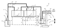
図2は、本発明の第1の実施形態に係る第1の印刷部3のインクジェット印刷部31の構成を示す構成図である。
FIG. 2 is a configuration diagram showing a configuration of an
図2に示すように、インクジェット印刷部31は、搬送ベルト23上の錠剤に対向して位置するインクジェットヘッド311を備えている。このインクジェットヘッド311は、ノズルNを備えており、このノズルNからインクが吐出されることで錠剤に対して印刷が行われる。また、パージやダミー吐出といったメンテナンス処理が行われる場合にも、ノズルNからインクが吐出される。
As shown in FIG. 2, the
インクジェットヘッド311には、インクボトルBからのインクの供給を受けるためのインクの供給管34が接続されている。すなわち、インクの供給管34の一端は、インクジェットヘッド311のインクの供給口INを介してインクジェットヘッド311に接続されており、その他端はインクボトルBに接続されている。インクの供給管34は、例えば可撓性を備える管を好適に使用することができる。
An
また、一般的には、インクの供給管34の途中には、インクボトルBからインクジェットヘッド311に対してインクの供給を行い、或いは、供給を停止することができるようにバルブが設けられているが、第1の実施形態では、このようなバルブは設けられていない。
Further, in general, a valve is provided in the middle of the
インクボトルBは、印刷処理、或いは、メンテナンス処理(以下、まとめて印刷処理等と表わす)において使用されるインクを収容するボトルである。このインクボトルBには、例えば、一日の印刷処理等において使用され、補充せずに使い切ることのできる量のインクが収容されている。 The ink bottle B is a bottle that houses ink used in a printing process or a maintenance process (hereinafter collectively referred to as a printing process or the like). The ink bottle B contains, for example, an amount of ink that is used in a printing process for one day and can be used up without replenishment.
なお、第1の実施形態に係る錠剤印刷装置Sでは、人が口に入れる錠剤に対しても印刷を行う。このため、例えば様々な異物等がインクに混入したり、インク自体が劣化したりすることを防止するために、例えば一日の印刷処理等で使い切ることが望ましい。また、場合によっては、インクボトルBに対して他のタンク等からインクを補給することによって、インクボトルB内のインクに対して、異物の混入がしやすくなったり、消費期限が管理しにくくなったりすることがあるため、インクボトルBを使い切り用とすることが望ましい。 In addition, in the tablet printing apparatus S according to the first embodiment, printing is also performed on a tablet that a person puts in the mouth. Therefore, for example, in order to prevent various foreign substances from being mixed into the ink or the ink itself from deteriorating, it is desirable to use up the ink in, for example, a day's printing process. Further, in some cases, by replenishing the ink bottle B with ink from another tank or the like, it becomes easy for foreign matter to be mixed into the ink in the ink bottle B, and it becomes difficult to manage the expiration date. Therefore, it is desirable to use up the ink bottle B.
そこで、第1の実施形態におけるインクボトルBには、例えば、一日の印刷処理等にて使い切ることのできる量のインク、或いは、この使い切ることのできる量に誤差などの余分を見込んだ量のインクが収容される。 Therefore, the ink bottle B in the first embodiment contains, for example, an amount of ink that can be used up in a day's printing process or the like, or an amount that allows an extra error or the like to be used up. Ink is stored.
このため、例えば、印刷処理等が開始される前に新しいインクボトルBが用意され、印刷処理等にて必要なインク量が使用される。そして一日の印刷処理等が終了すると、インクが残っていたとしてもインクボトルBも交換されることになる。なお、交換されたインクボトルBは、それを洗浄することで再利用することが可能である。洗浄が困難である場合には、インクボトルBを使い捨てとすることもできる。 Therefore, for example, a new ink bottle B is prepared before the printing process or the like is started, and the amount of ink required for the printing process or the like is used. Then, when the printing process for one day is completed, the ink bottle B will be replaced even if the ink remains. The replaced ink bottle B can be reused by cleaning it. If cleaning is difficult, the ink bottle B can be disposable.
この時、インクボトルBだけでなく、インクの供給管34も交換する。これは、インクの供給管34内に残存するインク自体も必ず使い切りとするためである。したがって、インクの供給管34に開閉バルブが存在すると、この開閉バルブごと交換することになる。
At this time, not only the ink bottle B but also the
つまり、インクの交換毎に開閉バルブも廃棄されることになり、ランニングコストが高くなってしまう。また、開閉バルブを洗浄し再利用するとなると、その洗浄が確実になされたかの確認が必要となり、このような洗浄や洗浄の確認の工程により、やはりランニングコストは高まることになる。 That is, the on-off valve is also discarded every time the ink is replaced, which increases the running cost. Further, when the on-off valve is cleaned and reused, it is necessary to confirm whether the cleaning has been performed reliably, and the running cost will also increase by such a cleaning and cleaning confirmation process.
インクボトルBの上部には、管B1が接続されており、その管B1には、バルブB2が設けられている。これらの管B1とバルブB2は、インクボトルB内を大気開放する際に用いられる。 A tube B1 is connected to the upper part of the ink bottle B, and a valve B2 is provided in the tube B1. These tubes B1 and valve B2 are used when the inside of the ink bottle B is opened to the atmosphere.
また、インクボトルBの上部には、インクボトルB内に収容されているインクに対して圧力を掛けるための、図示しない加圧装置につながる管351も接続されている。インクボトルBと加圧装置とをつなぐ管351の途中には、バルブ352が設けられており、加圧処理に応じてバルブ352の開閉が行われる。
Further, a
なお、バルブB2及びバルブ352のいずれも、手動により、或いは、制御部5からの指示に基づき、その開閉が制御されるようにされていても良い。
The opening and closing of both the valve B2 and the
インクボトルBは、インクボトルB内に収容されるインクの液面Lの高さL2をを所定の高さに維持するための移動装置36上に載置される。移動装置36は、インクボトルBを載置する載置台361と、この載置台361を移動させる移動機構362と、移動機構362を駆動する駆動装置363とから構成されている。
The ink bottle B is placed on a moving device 36 for maintaining the height L2 of the liquid level L of the ink contained in the ink bottle B at a predetermined height. The moving device 36 includes a mounting table 361 on which the ink bottle B is placed, a moving
なお、図2においては特に図示していないが、例えば、載置台361上に載置されたインクボトルBの転倒等を防止するための器具、装置等が設けられていても良い。 Although not particularly shown in FIG. 2, for example, an instrument, a device, or the like for preventing the ink bottle B placed on the mounting table 361 from tipping over may be provided.
載置台361は、移動機構362が駆動装置363からの駆動力をもって駆動されることによって、図2に示すZ軸方向に移動する。このように載置台361がZ軸方向に移動することによってインクボトルBも合わせて移動する。
The mounting table 361 moves in the Z-axis direction shown in FIG. 2 when the moving
移動機構362は、ここでは、例えば、ボールねじなどインクボトルBをZ軸方向に移動させることが可能な機構であれば、各種の機構を採用することができる。
Here, as the moving
駆動装置363は、移動機構362に駆動力を付与してインクボトルBをZ軸方向に移動させる。この駆動装置363は、図1に示す制御部5に電気的に接続されており、その制御部5からの制御信号に基づいて移動機構362を駆動する。
The
駆動装置363としては、例えば移動機構362がボールねじを採用している場合には、ボールねじを回転させるモータ等を採用することができる。但し、移動機構362によって載置台361(インクボトルB)をZ軸方向に移動させることができる駆動力を与えることが可能であれば、どのような装置を採用しても良い。
As the
インクジェットヘッド311には、排出管37が接続されている。この排出管37の途中には、バルブ371が設けられている。このバルブ371についても、手動、或いは、制御部5からの指示に基づき、その開閉が制御される。
A
排出管37の一端は、インクジェットヘッド311のインクの排出口OUTを介してインクジェットヘッド311に接続されており、その他端は、排出したインクを受け取る排出ボトルBEに接続されている。そして、この排出管37の他端、つまり排出管37の排出ボトルBE側の端面の高さは、インクボトルB内の液面Lより低い高さに設定する。
One end of the
なお、第1の実施形態においては、例えば1日の印刷処理等においてインクボトルB内に収容されているインクを使い切ることを前提としている。従って、インクジェットヘッド311内に残ったインクをインクボトルBへと戻すことはせず、印刷処理等が終了したら、排液管37よりインクジェットヘッド311内のインクは排液される。つまり、インクジェットヘッド311内や配管に残ったインクは、排出ボトルBEに排出される。排出ボトルBEには、その上部に、排出ボトルBE内を大気開放する管B3が接続されている。
In the first embodiment, it is premised that the ink contained in the ink bottle B is used up in, for example, a printing process for one day. Therefore, the ink remaining in the
排出管37は、例えば可撓性を備える管を好適に使用することができる。
As the
また、排出管37の途中には、排出管37中を流れる液体の色や濁り状態を観察するセンサKEが設けられている。
Further, in the middle of the
このセンサKEは、後述のように、例えばインクボトルBを交換し、印刷の準備としてインクジェットヘッド311内や配管内にインクを充填する時、排出管37にインクが到達したかどうかを検知して、充填が完了したことを検出することや、インクジェットヘッド311内や配管内の洗浄を行う場合、純水等の洗浄液がインクと混じって着色あるいは混濁した状態から、無色透明、あるいは混濁がなくなったことを検知して、洗浄が完了したことを検出するためのものである。
As will be described later, this sensor KE detects whether or not the ink has reached the
従来、このような洗浄の完了は目視や時間等で判断していたが、インクの濃度や洗浄液への溶解度などの影響で、洗浄の状態もバラツキがあった。また、目視ではその判断にバラツキが生じていた。この点、上述のように配管あるいは配管内の液体の透明度や混濁状態をセンサKEで検知することで、洗浄の完了判断のバラツキは抑制される。 Conventionally, the completion of such cleaning has been judged visually or by time, etc., but the cleaning condition also varies due to the influence of the ink concentration and the solubility in the cleaning liquid. In addition, there were variations in the judgment visually. In this regard, by detecting the transparency and turbidity of the pipe or the liquid in the pipe with the sensor KE as described above, the variation in the determination of the completion of cleaning can be suppressed.
なお、このような検知としては、検知対象の吸光度、透過率、反射の状態などで行うことができ、このような状態を検知可能なセンサで有ればどのようなものでも適用できる。また、カメラ等の撮像により透明度や混濁状態を検知しても良い。 It should be noted that such detection can be performed depending on the absorbance, transmittance, reflection state, etc. of the detection target, and any sensor that can detect such a state can be applied. Further, the transparency and the turbid state may be detected by imaging with a camera or the like.
上述したように、インクボトルB内には印刷処理等において使用されるインクが収容されている。そして、印刷処理等においてインクジェットヘッド311からインクを吐出可能とするため、インクの供給管34を通じてインクボトルBからインクジェットヘッド311へとインクが供給される。インクジェットヘッド311に対してインクボトルBから適切にインクが供給されるように、定められた水頭差を維持する必要がある。
As described above, the ink bottle B contains ink used in printing processing and the like. Then, in order to enable the ink to be ejected from the
(水頭差)
第1の実施形態においては、図2に示すように、インクジェットヘッド311のノズルNが形成されるノズル形成面312の高さL1とインクボトルB内に収容されるインクの液面Lの高さL2との差が、制御すべき水頭差であり、前述の維持する必要がある定められた水頭差である。図2において符号h1で示している(供給側の水頭差)。水頭差のh1は、印刷処理時においては、インクジェットヘッド311のノズル形成面312の高さL1を基準に、インクボトルB内のインクの液面Lの高さL2を下にする。従って、図2においてもノズル形成面312の高さよりもインクボトルB内の液面Lの高さが下となるように示されている。
(Head difference)
In the first embodiment, as shown in FIG. 2, the height L1 of the
この水頭差のh1は、インクジェットヘッド311内に負圧を生じさせるためのものであり、インクジェットヘッド311のノズルN内に生じるインクのメニスカスによる表面張力Mとの関係で、負圧が大きければインクジェットヘッド311内に外気が侵入することになり、負圧が小さければノズルNよりインクが漏れ出ることになる。したがって、インクジェットヘッド311にインクが充填された後は、ノズルNから外気が侵入せず、かつインクが漏れ出ない負圧となる水頭差(所定の水頭差)に維持する。
The h1 of the water head difference is for generating a negative pressure in the
また、印刷処理中において、水頭差のh1の変化が大きいと、ノズルNから吐出されるインク量も大きく変化してしまう。錠剤印刷装置Sにおいて、錠剤に対して印刷を行う場合、印刷に使用されるインク量が微小であるため、吐出されるインク量が大きく変化すると、印刷のかすれやにじみが生じることになる。よって、錠剤への印刷が適切に行われない。このため、吐出されるインク量を安定させるためにも、少なくとも印刷処理が行われている最中、水頭差のh1を所定値に維持する。 Further, if the change in h1 of the head difference is large during the printing process, the amount of ink ejected from the nozzle N also changes significantly. When printing on a tablet in the tablet printing apparatus S, since the amount of ink used for printing is very small, if the amount of ink ejected changes significantly, printing faintness or bleeding will occur. Therefore, printing on tablets is not performed properly. Therefore, in order to stabilize the amount of ejected ink, h1 of the head difference is maintained at a predetermined value at least during the printing process.
インクボトルB内のインクの液面Lの高さL2(以下、インク液面Lの高さL2とする)は、基準面からインクボトルBの底面までの高さL3と、インクボトルBの底面からインクボトルB内のインクの液面Lまでの高さとの合計である。基準面は、例えば、第1の印刷部3におけるベース板などの共通の土台の上面である。この上面には、駆動装置363などが載置されている。
The height L2 of the ink liquid level L in the ink bottle B (hereinafter referred to as the height L2 of the ink liquid level L) is the height L3 from the reference surface to the bottom surface of the ink bottle B and the bottom surface of the ink bottle B. It is the sum of the height from the ink to the liquid level L of the ink in the ink bottle B. The reference surface is, for example, the upper surface of a common base such as a base plate in the
水頭差のh1の所定値は、錠剤への印刷に適した水頭差の幅を有する所定の許容範囲内で決められる。具体的には、インクジェットヘッド311のノズル形成面312の高さL1とインクタンクB内のインク液面の高さL2との差である水頭差のh1は、例えば−5mmから+5mmの間というように、ある幅をもって許容された所定の許容範囲内で設定される。なお、印刷処理等での使用上許容できる水頭差のh1およびその範囲については、インクジェットヘッド311内の流路構成や形状、ノズルNの断面形状や孔径、使用するインクの組成、粘度や比重などの特性、流路上の損失等によって影響されるため、実験等で決められる。また、水頭差のh1については、ある範囲内にあることが求められるが、この範囲についてもインクジェットヘッド311の上述した条件ごとに異なる。
The predetermined value of h1 of the head difference is determined within a predetermined allowable range having a width of the head difference suitable for printing on tablets. Specifically, the head difference h1, which is the difference between the height L1 of the
また、インクジェットヘッド311は、ノズルNが形成されているノズル形成面312の高さL1とインクボトルB内におけるインクの液面Lの高さL2との水頭差のh1の維持を図るために、インクジェットヘッド311は移動することはない。もちろん、印刷対象となる錠剤とのインク吐出距離を調整するためにインクジェットヘッド311が移動することはあるが、水頭差のh1の維持を行うに当たってインクジェットヘッド311が移動することはない。これにより、印刷時、錠剤とインクジェットヘッド311の距離が変動しないため、吐出されたインクが錠剤に到達する到達距離が一定となるため、小さな錠剤への印刷であってもきれいな印刷を行うことができる。
Further, the
(印刷処理中の水頭差の維持方法)
第1の実施形態では、少なくとも印刷処理が行われている最中、できるだけ水頭差のh1を一定に維持するようにしている。
(How to maintain the head difference during printing)
In the first embodiment, h1 of the head difference is maintained as constant as possible at least during the printing process.
そこで、以下、適宜図面を使用しながら、印刷処理等の最中に水頭差のh1を所定値に維持する方法について説明する。 Therefore, a method of maintaining the head difference h1 at a predetermined value during a printing process or the like will be described below while appropriately using drawings.
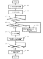
図3は、第1の実施形態に係る錠剤印刷の流れを示すフローチャートである。ここでは、例えば、1日における錠剤への印刷処理等の流れを示している。 FIG. 3 is a flowchart showing the flow of tablet printing according to the first embodiment. Here, for example, the flow of printing processing on tablets in one day is shown.
図3に示すように、まず印刷処理等を開始するに当たって、載置台361にインクボトルBを載置する(ST1)。 As shown in FIG. 3, first, when starting the printing process or the like, the ink bottle B is placed on the mounting table 361 (ST1).
載置台361に載置されたインクボトルBには、インクジェットヘッド311に対してインクの供給を行うことができるように、インクの供給管34が接続される。また、加圧装置につながる管351もインクボトルBの上部に接続される。さらに、インクボトルB上部には、バルブB2を備える管B1も接続される。
An
インクボトルBの準備が整うと、次に、インクジェットヘッド311に対するインクの充填が行われる(ST2)。このインクの充填処理では、まず、加圧装置とインクボトルBとをつなぐ管351に設けられているバルブ352、及び、排出管37に設けられているバルブ371を開く。この時、バルブB2は閉じられている。その上で、加圧装置を用いてインクボトルB内のインクに対して圧力を掛ける。
When the ink bottle B is ready, the
この圧力印加に応じて、インクボトルB内のインクは、インクの供給管34を通ってインクジェットヘッド311内に充填される。インクジェットヘッド311内にインクが充填されると、それ以降にインクジェットヘッド311内からあふれたインクは排出管37を介してインクジェットヘッド311の外へと排出される。
In response to this pressure application, the ink in the ink bottle B is filled in the
制御部5は、充填処理が行われている間、インクジェットヘッド311内がインクで満たされたか否か、すなわちインクの充填処理が終了したか否かを随時確認する(ST3)。これは、排出管37にインクが到達すれば、インクジェットヘッド311内の流路(図2のインクジェットヘッド311内に破線で示す)がインクで満たされたことを示し、充填処理が終了したと判断することができる。したがって、例えば、排出管37に設けたセンサKEによって、排出管37内にインクがあるかどうかを検出することや、排出管37からのインクの排出を検出することで、充填処理が終了したとみなすことができる(ST3のYES)。充填作業が終了したと判断されると、排出管37のバルブ371が閉じられる。
While the filling process is being performed, the
なお、ここでは加圧装置を利用する例を挙げて充填処理を行うことを説明したが、例えば、インクボトルB自体を、少なくともインクタンクB内の液面がノズル形成面312よりも高くなるように上昇させることによって、充填処理を行うこともできる。もちろん、これらの方法を利用してパージ処理や洗浄処理も可能である。
Although the filling process has been described here with an example of using a pressurizing device, for example, the liquid level in the ink bottle B itself is at least higher than the
次に、制御部5は、インクジェットヘッド311のノズル形成面312の高さL1とインクボトルB内のインクの液面Lの高さL2との関係で水頭差を調整する必要があるか否か確認する(ST4)。
Next, whether or not the
ここで、図2に示すように、移動機構362の載置台361の移動経路中には、センサKが設置されている。このセンサKは、インクボトルB内のインク液面の高さL2を検出するためのものである。したがって、液面Lの検出ができれば良く、移動機構362以外に備えられていても良い。そして、このセンサKが液面Lを検出する高さL4は、インクボトルB内のインク液面の高さL2が、水頭差のh1が所定値となる高さより下に設置されている。
Here, as shown in FIG. 2, the sensor K is installed in the moving path of the mounting table 361 of the moving
制御部5は、充填処理が終了した時点で、インクボトルB内の液面LがセンサKで検出されるかどうかを確認する。制御部5は、センサKで液面が検出されていない場合には(ST4のYES)、検出されるまで載置台361をZ方向に上昇あるいは下降移動させるよう制御する。例えば、予め設定された距離あるいは時間、載置台361を上昇させても液面が検出されない場合には、載置台361を下降させる。制御部5は、センサKが液面を検出したら、載置台361を停止させる。このとき、センサKの設置高さ(液面検出高さ)L4が、インクボトルB内のインク液面の高さL2となる。つまり、水頭差のh1の所定値(所定の水頭差)と、現時点のインク液面の高さL2から算出される水頭差と、の差を算出することができる。制御部5は、この差がゼロになるように載置台361を駆動する。これにより、インクボトルB内のインク液面の高さL2は、水頭差のh1が所定値となる高さに調整される(ST5)。The
上述したように、充填処理が終了した時点で、排出管37のバルブ371が閉じられる。そしてインクジェットヘッド311からインクの吐出を開始するためには、さらに、加圧装置とインクボトルBとをつなぐ管351に設けられているバルブ352が閉じられる。一方、充填処理においては閉じているインクボトルBの上部に設けられているバルブB2が開かれ、大気開放される。この状態でインクボトルBからインクジェットヘッド311へインクが供給され、インクが吐出できるようになり、錠剤印刷装置SにおいてノズルNから錠剤へのインクの吐出が開始される(ST6)。
As described above, the
なお、充填処理が終了した時点では、大気解放を行わないほうが良い。インクタンクB内を加圧し続けることで、例えインクタンクB内のインクの液面が下がり過ぎても、インクジェットヘッド311からインクタンクBにインクが戻ることを抑制することができる。
It is better not to release to the atmosphere when the filling process is completed. By continuing to pressurize the inside of the ink tank B, it is possible to prevent the ink from returning from the
ここで、インク消費量に関して、例えば1日の印刷処理等により消費されるインクの量を予め把握しておくことが可能である。例えば、1日の印刷処理等において印刷対象となる錠剤の数は、予め定められている。そして、錠剤の印刷内容から、1つの錠剤に対して使用されるインクの量も予め定められている。これらの情報から、例えば、1日の印刷処理等により消費されるインクの量が把握される。その上で、錠剤の印刷数当たりの、あるいは、印刷処理の単位時間当たりのインクの消費量を把握することが可能となる。 Here, regarding the amount of ink consumed, for example, it is possible to grasp in advance the amount of ink consumed by the daily printing process or the like. For example, the number of tablets to be printed in a daily printing process or the like is predetermined. The amount of ink used for one tablet is also predetermined from the printed content of the tablet. From this information, for example, the amount of ink consumed by the daily printing process or the like can be grasped. Then, it becomes possible to grasp the amount of ink consumed per number of tablets printed or per unit time of the printing process.
このような印刷数や単位時間当たりのインクの消費量は、すなわち、インクボトルB内から消費されるインクの量である。インクボトルBの内径も予め把握できることから、結果として印刷数や単位時間当たりのインクボトルBにおける液面Lの高さの変化も把握できることになる。したがって、印刷数や単位時間当たりの水頭差のh1の変化を把握することができる。 The number of such prints and the amount of ink consumed per unit time are, that is, the amount of ink consumed from the inside of the ink bottle B. Since the inner diameter of the ink bottle B can be grasped in advance, as a result, it is possible to grasp the number of prints and the change in the height of the liquid level L in the ink bottle B per unit time. Therefore, it is possible to grasp the change in the number of prints and the change in the head difference h1 per unit time.
図4は、図2に示すインクボトルB内のインクが消費されて、インクタンクBが上昇した状態を示す図である。従って第1の印刷部3の構成を説明する際に用いた図2とその構成に変化はないが、インクボトルBの高さL3が異なる。
FIG. 4 is a diagram showing a state in which the ink in the ink bottle B shown in FIG. 2 is consumed and the ink tank B is raised. Therefore, there is no change in the configuration of FIG. 2 used when explaining the configuration of the
図2では、図3のステップST1において説明したように、新しいインクボトルBが載置台361に載置された状態が示されている。そのためインクボトルB内にはインクが十分に収容されており、その際の液面Lの高さL2に合わせて、水頭差のh1が所定値となるように、インクボトルBの高さL3が位置付けられている状態が示されている。 FIG. 2 shows a state in which the new ink bottle B is placed on the mounting table 361 as described in step ST1 of FIG. Therefore, the ink is sufficiently contained in the ink bottle B, and the height L3 of the ink bottle B is set so that the head difference h1 becomes a predetermined value according to the height L2 of the liquid level L at that time. The positioned state is shown.
一方、図4では、印刷処理等が進みノズルNからのインクの吐出により、インクボトルB内のインクが使用されて、インクボトルB内における液面Lの高さが低くなった状態を示している。そして、低くなったインクタンクB内のインクの液面Lを、移動装置36を用いてインクタンクB自体を上方へと移動させ、水頭差のh1が所定値となるように位置付けた状態が示されている。つまり、印刷処理が進んでインクが消費されても、水頭差のh1は所定値に維持されていることが示されている。 On the other hand, FIG. 4 shows a state in which the height of the liquid level L in the ink bottle B is lowered due to the use of the ink in the ink bottle B due to the progress of the printing process and the ejection of the ink from the nozzle N. There is. Then, the liquid level L of the ink in the lowered ink tank B is moved upward by using the moving device 36, and the state where the head difference h1 is positioned to be a predetermined value is shown. Has been done. That is, it is shown that even if the printing process progresses and the ink is consumed, the head difference h1 is maintained at a predetermined value.
図3のステップST7に示すように、予め把握している印刷処理等において使用されるインクの量から、印刷数や単位時間でのインクボトルB内における液面Lの低下の状態を予測することができる。そこで、この液面Lの低下の予測状態に合わせてインクボトルB自体を上方へと移動させることで液面Lの高さ、すなわちインク液面の高さL2の変化を相殺し、水頭差のh1を所定値に維持する。 As shown in step ST7 of FIG. 3, the state of the decrease in the liquid level L in the ink bottle B in the number of prints and the unit time is predicted from the amount of ink used in the printing process or the like that is grasped in advance. Can be done. Therefore, by moving the ink bottle B itself upward in accordance with the predicted state of the decrease in the liquid level L, the change in the height of the liquid level L, that is, the height L2 of the ink liquid level is canceled out, and the head difference is increased. Keep h1 at a predetermined value.
このように予めインクボトルBにおけるインクの液面Lの高さの変化を把握しておくことで、印刷処理等によってインクが消費され、次第にインクボトルB内における液面Lが下がることに対応して、水頭差のh1を所定値に維持するようにインクボトルB内のインク液面の高さL2を変化させないようにすることができる。例えば、所定の錠剤数毎や所定の単位時間毎に、先に述べたインクボトルB内の液面Lの高さの変化分、載置台361を上昇させるように制御する。
By grasping the change in the height of the ink liquid level L in the ink bottle B in advance in this way, the ink is consumed by the printing process or the like, and the liquid level L in the ink bottle B gradually decreases. Te can be Rukoto so as not to change the height L2 of the ink surface in the ink bottle B to maintain the h1 water head difference to a predetermined value. For example, the mounting table 361 is controlled to be raised by the change in the height of the liquid level L in the ink bottle B described above for each predetermined number of tablets or for each predetermined unit time.
しかも、単にインクボトルBの高さを変化させるのではなく、事前に把握されているインクボトルBにおけるインクの液面Lの高さの変化に関する情報を利用してインクボトルB内におけるインクの液面Lの高さを極力変化させず維持するようにインクボトルBを移動させることが可能である。 Moreover, instead of simply changing the height of the ink bottle B, the ink liquid in the ink bottle B is used by utilizing the information on the change in the height of the ink liquid level L in the ink bottle B that is grasped in advance. It is possible to move the ink bottle B so as to maintain the height of the surface L as unchanged as possible.
上述したように、事前に把握されている単位時間に消費されるインクの量に関する情報に基づいて、インクボトルB内の液面Lの高さが水頭差のh1を維持するようにインクボトルBの高さを徐々に変化させていくように制御すれば、安定的にインクジェットヘッド311にインクを供給できる。
As described above, the ink bottle B is such that the height of the liquid level L in the ink bottle B maintains the head difference h1 based on the information regarding the amount of ink consumed in the unit time that is grasped in advance. Ink can be stably supplied to the
前述のステップST5の後、印刷処理等によってインクジェットヘッド311のノズルNからインクの吐出が開始されると、予め把握されているインクの使用量に合わせてインクボトルBを上方へと移動させるべく、制御部5は移動装置36の駆動装置363を制御する(ST7)。
After the above-mentioned step ST5, when the ink ejection is started from the nozzle N of the
このとき、予め消費されるインクの量を把握しておき、このインクの量の情報を基に、印刷処理等にインクが使用されることで収容されているインク量が減少しインクボトルB内での液面Lの高さが低くなったとしても、その変化に合わせてインクボトルBの高さL3が高くなるように移動装置36を用いてインクボトルBを上方へと移動させる制御を行う。これにより、印刷処理等によりインクボトルB内のインクが使用されてその液面Lの高さが低くなったとしても常に水頭差のh1を所定値に維持することができる。 At this time, the amount of ink consumed is grasped in advance, and based on the information on the amount of ink, the amount of ink contained is reduced by using the ink for printing processing or the like, and the inside of the ink bottle B Even if the height of the liquid level L becomes low, the moving device 36 is used to control the movement of the ink bottle B upward so that the height L3 of the ink bottle B becomes high according to the change. .. As a result, even if the ink in the ink bottle B is used by the printing process or the like and the height of the liquid level L is lowered, the head difference h1 can always be maintained at a predetermined value.
制御部5は印刷処理等が終了したか否かを随時判断する(ST8)。例えば、制御部5は、ホッパ15からの錠剤の供給が終了したとき、あるいはオペレータによる操作ボタンの押下によって、印刷処理等が終了したと判断する。制御部5は錠剤印刷装置Sによる錠剤への印刷処理等が終了したことをもって、移動装置36に対してインクボトルBの移動も終了するよう指示する。
The
印刷処理等が終了すると、載置台361からこれまで使用されたインクボトルBが撤去されて、改めて載置台361は、下方へと移動し、次のインクボトルBが載置されることに備える(ST9)。この載置台361の下方への移動について、制御部5は、次に使用されるインクを収納するインクボトルB内におけるインクの液面Lの高さ(水頭差のh1)を考慮して、その移動距離を駆動装置363に指示する。
When the printing process or the like is completed, the ink bottle B used so far is removed from the mounting table 361, and the mounting table 361 moves downward again to prepare for the next ink bottle B to be placed (). ST9). Regarding the downward movement of the mounting table 361, the
以上説明したように、第1の実施形態によれば、予め使用されるインクの量を把握することで印刷数や単位時間当たりのインクの消費量を把握することができる。このため、その消費量に基づいてインクボトルB自体の高さを調整することによって、インクボトルからインクジェットヘッド311に対してインクを供給する際に、設定されたインクジェットヘッド311のノズル形成面312の高さL1とインクボトルB内のインクの液面Lの高さL2との水頭差のh1を所定値に維持することが可能となる。これにより、インクジェットヘッド311からのインクの吐出量を安定させることができ、錠剤への印刷を良好に行うことができる。従って、錠剤のように小さな印刷対象物に適切に印刷を行うことのできる錠剤印刷装置及び錠剤印刷方法を提供することができる。
As described above, according to the first embodiment, it is possible to grasp the number of prints and the amount of ink consumed per unit time by grasping the amount of ink used in advance. Therefore, by adjusting the height of the ink bottle B itself based on the consumption amount, when the ink is supplied from the ink bottle to the
また、小さな錠剤への印刷では、水頭差のh1の少しの変化が、吐出されるインク量の大きな変化となって現れる。第1の実施形態では、ほぼリアルタイムで水頭差のh1を所定値に維持することができるので、吐出されるインク量の大きな変化はなく、印刷のかすれやにじみが生じることなく錠剤への印刷が適切に行われる。 Further, in printing on a small tablet, a slight change in h1 of the head difference appears as a large change in the amount of ink to be ejected. In the first embodiment, since the head difference h1 can be maintained at a predetermined value in almost real time, there is no significant change in the amount of ink ejected, and printing on tablets can be performed without causing faintness or bleeding of printing. It is done properly.
また、第1の実施形態においては、水頭差のh1の維持を行うためにインクジェットヘッド311を移動させない。つまり、錠剤への印刷の間、インクジェットヘッド311は固定される。したがって、錠剤とインクジェットヘッド311との間隔は、印刷に最適な間隔となり、その間隔は変わらない。よって、インクが吐出されて錠剤に到達するまでの距離が一定となり、小さな錠剤への印刷であっても綺麗な印刷を行うことができる。
Further, in the first embodiment, the
ところで、インクの成分によっては、インク内でその組成部が凝集し、凝集体が形成される場合がある。このような凝集体があると、インクジェットヘッド311内の流路において抵抗を増やすことになり、インクの流れが妨げられる。また、凝集体のサイズが、インクジェットヘッド311のノズル径より大きいと、ノズルNが詰まって吐出できなくなったりする。
By the way, depending on the components of the ink, the composition portion thereof may aggregate in the ink to form an agglomerate. The presence of such agglomerates increases resistance in the flow path in the
インクボトルB内で凝集している凝集体は、インクの供給管34上にフィルタFを設けることで、インクジェットヘッド311に到達しないように濾し取ることができる。(図8参照)
例えば、凝集体のサイズが15μm〜30μm程度であると、インクの吐出に影響する。したがって、フィルタによって10μm以上の凝集体は通さないようにすると良い。
The agglomerates that have agglomerated in the ink bottle B can be filtered out so as not to reach the
For example, when the size of the agglomerates is about 15 μm to 30 μm, it affects the ejection of ink. Therefore, it is advisable to prevent agglomerates of 10 μm or more from passing through the filter.
しかし、印刷処理中にも凝集は進み、供給管34やインクジェットヘッド311内で凝集体の発生、成長することがあり、この場合、凝集体のサイズが上記15μm〜30μm程度になる前に、インクジェットヘッド311内より排除する必要がある。すなわち、凝集体が吐出に影響を与えないサイズのうちに、定期的にインクジェットヘッド311内のインクを排出する排出処理を行うようにする。
However, agglomeration may proceed even during the printing process, and agglomerates may be generated and grow in the
このため、予め使用するインクの種類毎に凝集体のサイズが吐出に影響を与えるサイズに成長する時間(排出間隔時間)を、実験等で求めて、制御部5に記憶させておく。このような排出間隔時間は、例えば1分〜30分程度である。
Therefore, the time (discharge interval time) at which the size of the agglomerates grows to a size that affects the ejection for each type of ink used in advance is obtained by an experiment or the like and stored in the
インクジェットヘッド311による印刷処理が開始されると同時に、制御部5は、印刷処理時間(印刷時間)の計時を開始する。上記排出間隔時間が到達したら、印刷処理を停止する。次に排出管37のバルブ371を開く。これにより、供給管34やインクジェットヘッド311内のインクは排出管37を経由して排出される。
At the same time that the printing process by the
上述のように、排出管37の一端はインクジェットヘッド311の排出口OUTに接続され、他の一端はインクボトルB内のインクの液面Lより下になるように設置されている。
As described above, one end of the
したがって、インクボトルB内のインクの液面Lとの水頭差によって、インクジェットヘッド311内のインクが排出される。
Therefore, the ink in the
インクの排出が始まってから所定時間経過する事を制御部5によって計時しており、所定時間排出がされた時に、バルブ371を閉じる。この所定時間は、少なくともインクジェットヘッド311のインク供給口INからインク排出口OUTの間のインクが、インク排出口OUTより排出管37内へ移動するだけの時間で有ればよい。より好ましくは、インクの供給管34内のインクを含めてインクの排出管37内へ移動するだけの時間で有ればよい。また、後述の図8に示すように、インクの供給管34にフィルタFが設けられている場合は、フィルタFよりインクジェットヘッド311側のインクの供給管34内のインクがインクの排出管37内へ移動するだけの時間としても良い。すなわち、インクジェットヘッド311内のインクの排出には、インクの供給管34内のインクを含まれる。
The
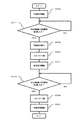
具体的には、図5に示すように、印刷処理(ST10)が行われている間、制御部5は上記凝集体を排出するまでの経過時間を計時している(ST11)。この経過時間が排出間隔時間に到達する、すなわち印刷時間が所定時間経過すると、印刷処理を停止し(ST12)、排出管37のバルブ371を開く(ST13)。すると、インクボトルB内の液面Lから排出管37の排出ボトルBE側の端面までの水頭差であるh2による差圧で、排出管37内のインクが排出ボトルBEに流れ込むことで排出処理が行われる(ST14)。したがって、インクジェットヘッド311内、インクの供給管34内のインクも排出ボトルBEに向かって流れる。
Specifically, as shown in FIG. 5, while the printing process (ST10) is being performed, the
この排出処理が開始されると、制御部5は、排出している時間(排出時間)を計時する。そして所定の排出時間、例えば事前に実験等で確認しているインクジェットヘッド311の供給口INから排出口OUTまでインクが流れる時間の経過後、バルブ371を閉じて排出処理を終了する。(ST15、ST16)。排出処理が終了したら、また印刷処理を再開する(ST17)。
When this discharge process is started, the
上記排出処理を行うために、図2に示すように、インクジェットヘッド311のインクを吐出するノズル形成面312を基準とし、インクボトルB内のインクの液面Lまでの高さ(水頭差)をh1(供給側の水頭差)、インクボトルB内のインクの液面Lから排出管37の排出側端面までの高さ(水頭差)をh2、ノズル形成面312から排出管37の排出側端面までの高さ(水頭差)をh3(排出側の水頭差)とした時、各高さ(各水頭差)が下記の関係となるように配置される。なお、理解を容易とするため、図中の各水頭差の図示は誇張して表現されている。
In order to perform the discharge process, as shown in FIG. 2, the height (head difference) of the ink in the ink bottle B to the liquid level L is set with reference to the
第1の実施形態において、インクの供給管34のインクボトルB側の端面は、インクボトルB内のインク内に位置するように配置される。また、排出管37の排出側端面は、排出ボトルBE内の排液面の上に位置するように配置される。
In the first embodiment, the end face of the
そして、少なくとも印刷処理の間、インクボトルB内のインクの液面Lは、インクジェットヘッド311のノズル形成面312と同じかノズル形成面312より下に位置する。 また、排出管37の排出側端面は、インクジェットヘッド311のノズル形成面312より下であって、かつインクボトルB内のインクの液面Lより下に位置する。したがって、水頭差のh1と水頭差のh3とは、h3の方がh1より大きい(h3>h1)。
Then, at least during the printing process, the liquid level L of the ink in the ink bottle B is located at the same level as the
したがって、インクジェットヘッド311のノズル形成面312からインクボトルB内の液面Lまでの水頭差のh1、インクボトルB内のインクの液面Lから排出管37の排出側端面までの水頭差のh2、インクジェットヘッド311のノズル形成面312から排出管37の排出側端面までの水頭差のh3の関係は、水頭差のh2が、水頭差のh3とh1の差分であり、h2=h3−h1となる。
Therefore, h1 of the head difference from the
また、前述の充填処理により、インクの供給管34内、インクジェットヘッド311内、排出管37内はインクで満たされた後、排出管37のバルブ371は閉じられるので、充填処理が終了している状態では、インクジェットヘッド311のノズル形成面312には、インクボトルB内の液面Lとの水頭差であるh1によって生じる背圧がかかることになる。
Further, by the above-mentioned filling process, the inside of the
ところで、インクジェットヘッド311のノズル形成面312の各ノズル内の液面(メニスカス)には表面張力Mが発生しており、この表面張力Mとインクジェットヘッド311内の圧力P(図2のインクジェットヘッド311に破線で示した流路内の圧力)の関係によって、ノズルNからインクが垂れたり、インクジェットヘッド311内に外気が吸い込まれたりしてしまう。つまり、圧力Pが正圧となり表面張力Mより大きくなると、ノズルNからインクが垂れてしまい、圧力Pが負圧となり表面張力Mより大きいと、ノズルNを介してインクジェットヘッド311内に外気が吸い込まれ、インクジェットヘッド311内に気泡が生じてしまうことがある。
By the way, a surface tension M is generated on the liquid surface (meniscus) in each nozzle of the
したがって、この表面張力Mと圧力P(背圧)が同じ程度になるように水頭差が調整される。 Therefore, the head difference is adjusted so that the surface tension M and the pressure P (back pressure) are about the same.
インクジェットヘッド311内の圧力Pが正圧となるのは、ノズル形成面312より上に(高く)インクボトルB内の液面Lが位置した時となる。そして、ノズルNよりインクが垂れてしまう圧力に圧力Pがなる水頭差をαとする。
The pressure P in the
また、インクジェットヘッド311のノズルNからインクがインクジェットヘッド311内に引き込まれ、外気が侵入してしまう負圧の圧力に圧力Pがなる水頭差をβとする。
Further, let β be the head difference at which the pressure P becomes the negative pressure in which the ink is drawn into the
これらの水頭差のαおよびβはゼロではない。したがって、表面張力Mと圧力P(背圧)の関係は、ノズルNからインクが垂れない状態からノズルNから外気が引き込まれるまでの幅をもつ。この幅は、絶対値で(α+β)となる。 The α and β of these head differences are not zero. Therefore, the relationship between the surface tension M and the pressure P (back pressure) has a width from the state where the ink does not drip from the nozzle N to the time when the outside air is drawn from the nozzle N. This width is (α + β) in absolute value.
第1の実施形態では、常にインクジェットヘッド311内の背圧は負圧として、インクの吐出の制御を簡素化するため、インクボトルB内のインクの液面Lの高さを、インクジェットヘッド311のノズル形成面312より高くしないで印刷処理を行う。したがってα=0とでき、上述のノズルNからインクが垂れない状態からノズルNから外気が引き込まれるまでの幅は、単にβとできる。つまり、印刷処理の際、インクジェットヘッド311内の背圧(圧力P)は、水頭差のh1がβ以内で設定されて、ノズルNより、インクが垂れず、外気を吸い込まないバランスした状態に制御される。
In the first embodiment, the back pressure in the
排出処理を行うときは、排出管37のバルブ371を開く。すると、水頭差のh3とh1は、h3>h1の関係に設定されているので、インクボトルB内の液面Lから排出管37の排出ボトルBE側の端面までの水頭差であるh2による差圧で、排出管37内のインクが排出ボトルBEに流れ込む。
When performing the discharge process, the
この流れによって、インクジェットヘッド311内およびインクの供給管34や排出管37内の凝集体は、インクとともにインクジェットヘッド311より排出することができる。
By this flow, the agglomerates in the
この時、ノズルNから、インクが垂れず、かつ外気が引き込まれないためには、前述のように、インクジェットヘッド311内の圧力Pが上記βでの水頭差による圧力より小さい圧力となる必要がある。
At this time, in order that the ink does not drip from the nozzle N and the outside air is not drawn in, the pressure P in the
すなわち、水頭差のh1およびh3いずれもが、水頭差のβ以内で有ることが必要となる。すなわち、(h1<β、h3<β)。 That is, it is necessary that both h1 and h3 of the head difference are within β of the head difference. That is, (h1 <β, h3 <β).
以上のように、第1の実施形態では、h1は印刷処理のインクジェットヘッド311内を所定の背圧とする高さに、h3は排出処理の際に、h3>h1、h3<βとなる関係に配置される。
As described above, in the first embodiment, h1 has a height at which the inside of the
そして、定期的にインクの排出処理を行うことで、凝集体による吐出不良の発生を防ぐことができる。この際、上述の水頭差の関係により、排出管37に設けたバルブ371を開閉するだけで排出処理を行うことができ、簡素な制御とすることができる。また、インクジェットヘッド311のノズルNからインクが垂れることなく、かつインクジェットヘッド311内に外気が吸い込まれることなく排出処理を行うことができる。このため、排出処理の後、バルブ371を閉じるだけですぐに印刷処理に戻れるので、効率的な印刷処理が可能となる。
Then, by periodically performing the ink ejection process, it is possible to prevent the occurrence of ejection defects due to the agglomerates. At this time, due to the above-mentioned head difference, the discharge process can be performed only by opening and closing the
さらに、水頭差のみで排出処理ができるので、別な排出のための駆動源を用意したり、その制御の必要もなく、簡素な構成とできる。また、駆動源の駆動エネルギの消費も必要なくなり、低コストの装置、低ランニングコストの装置とできる。 Further, since the discharge treatment can be performed only by the head difference, there is no need to prepare a drive source for another discharge or control the discharge, and the configuration can be simplified. Further, it is not necessary to consume the driving energy of the driving source, and the device can be a low-cost device and a low running cost device.
また、インクの流路上の開閉バルブは、排出側のみで供給側には無くても良いから、配管経路や開閉バルブ制御の簡素化が図れる。特に供給側では、衛生上の理由からインクの配管も交換する場合、開閉バルブが含まれないので、開閉バルブを使い捨てとする場合のようにランニングコストが高くなることがない。 Further, since the on-off valve on the ink flow path is only on the discharge side and does not have to be on the supply side, the piping route and the on-off valve control can be simplified. In particular, on the supply side, when the ink pipe is also replaced for hygienic reasons, the on-off valve is not included, so the running cost does not increase as in the case where the on-off valve is disposable.
また、開閉バルブを再利用する場合、複雑な形状のバルブ内部を確実に洗浄することは時間もかかり、またきちんと洗浄されたかの検査にも時間がかかるため、再利用のコストも高くなってしまうが、このランニングコストも削除できる。 In addition, when reusing an on-off valve, it takes time to reliably clean the inside of a valve with a complicated shape, and it also takes time to inspect whether it has been properly cleaned, so the cost of reuse is high. , This running cost can also be deleted.
また、開閉バルブの金属部品からの不純物の溶出のリスクをなくすことができる。 In addition, the risk of elution of impurities from the metal parts of the on-off valve can be eliminated.
また、食用、薬剤等経口される錠剤の場合は、配管上の雑菌の繁殖はあってはならない。この点で、バルブを設けないことはそのリスクを確実に排除できる。 In addition, in the case of tablets that are taken orally such as foods and drugs, germs should not propagate on the pipes. In this respect, not providing a valve can certainly eliminate the risk.
なお、排出側のバルブ371以降は、インクは廃棄されるだけなので、汚染が残っていても問題にならない。
Since the ink is only discarded after the
なお、前述の説明では、ノズル形成面312から排出管37の排出側端面までの高さ(水頭差)をh3とした。つまり、第1の実施形態では、排出管37の排出ボトルBE側の端面は、排出ボトルBE内の液面より高い位置に設定されることになる。前述のように、一日のインクの使用量はわかっているので、排出されるインクの量もインクの使用量に相当するのでわかる。また、インクの充填や洗浄によるインクや洗浄液の排出量も予め設定することができる。したがって、最終的に到達する排出ボトルBE内の液面の高さも算出することができる。よって、この最終的に到達する液面より上となるように排出管37の排出ボトルBE側の端面が位置するように、排出管37や排出ボトルBEのサイズ、配置とすればよい。
In the above description, the height (head difference) from the
また、このような配置に限定せず、排出ボトルBE内の液面が上昇し、排出管37の端面が液面の下になるような場合でも、この排出ボトルBE内の液面を水頭差のh3の基準とすればよい。すなわち、図2に示すように、排出管37の端面が排出ボトルBE内の液面の上にある場合、排出側の水頭差のh3は、インクジェットヘッド311のノズル形成面312から排出管37の排出側端面までの高さであり、図6に示すように排出管37の端面が排出ボトルBE内の液面の下にある場合は、インクジェットヘッド311のノズル形成面312から排出ボトルBE内の液面までの高さとなる。
Further, the liquid level in the discharge bottle BE is not limited to such an arrangement, and even when the liquid level in the discharge bottle BE rises and the end surface of the
いずれの場合でも、水頭差のh3と、水頭差のh1、ノズルNから外気が引き込まれない水頭差の幅であるβとが、前述のようなh3>h1、h3<β、h1<βの関係となっていればよい。 In any case, the head difference h3, the head difference h1, and β, which is the width of the head difference at which outside air is not drawn from the nozzle N, are h3> h1, h3 <β, and h1 <β as described above. It suffices if it is a relationship.
この関係の限界となる排出ボトルBEの液面高さを、図示しないセンサで検出する、あるいは排出ボトルBEの重量を検出するなどして、排出ボトルBE内のインクや洗浄液等の排液の総量から液面高さを算出し、上記関係が崩れる限界値となった場合は、排出ボトルBEの交換や排液の排出ボトルBEからの排出を促す警告を出すようにすれば良い。 The total amount of drainage such as ink and cleaning liquid in the drainage bottle BE is detected by detecting the liquid level height of the drainage bottle BE, which is the limit of this relationship, with a sensor (not shown) or by detecting the weight of the drainage bottle BE. The liquid level height may be calculated from the above, and when the limit value at which the above relationship is broken is reached, a warning prompting the replacement of the discharge bottle BE or the discharge of the drainage from the discharge bottle BE may be issued.
供給側の水頭差のh1は概ね固定される所定値なので、排出ボトルBE内の排液の液面が、水頭差のh1より下に位置する高さでボトルの収容限界とするように、ボトルの配置、サイズを決定しても良い。 Since h1 of the head difference on the supply side is a predetermined value that is generally fixed, the bottle is set so that the liquid level of the drainage liquid in the drain bottle BE is at a height located below h1 of the head difference and is the storage limit of the bottle. You may decide the arrangement and size of.
このようにすれば、常に排液管37の端面が排出ボトルBE内の液面の上に位置する必要が無くなり、排出管37や排出ボトルBEの配置の自由性が高まり、より錠剤印刷装置を小さなものとすることができ、錠剤印刷装置の設置場所の自由度が高まる。
By doing so, it is not always necessary for the end face of the
また、第1の実施形態において、充填作業が終了したら排出管37のバルブ371が閉じられる説明をした。この充填作業の終了は、例えば、図2に示す排出管37に設けたセンサKEによってインクを検出することによる。この時の排出管37内のインクの端面(液面)は、排出管37の排出側の端面で、排出管37内がインクで満たされていることが望ましい。あるいは、少なくともセンサKEが検出することでバルブ371を閉じて、その時の排出管37内のインクの液面が、水頭差のh1より下にあるようにする。こうすることで、排出側の水頭差のh3は、その基準が排出管37内のインクの液面となるが、この液面による水頭差のh3は、h1より大きくなる。したがって、排出タイミングでバルブ371を開いた時に、h3>h1となり、排出管37から排出ボトルBEへとインクが排出される。もちろん、センサKEでのインクの検出を排出管37の排出側端面やその下で行ってもよい。確実に排出管37内がインクで満たされている事が検出できる。
Further, in the first embodiment, it has been described that the
(その他の実施形態)
ところで、錠剤表面の被印刷面全体にコーティングするように印刷処理する場合、インクの使用量は多くなり、前述のようにインクの組成部の凝集が進む前にインクが消費される場合がある。このような場合、錠剤の供給が止まる等で印刷処理の内、印刷を行えない時間、すなわち、印刷が停止している時間が、インクが凝集する時間となる。したがって、第1の実施形態における排出間隔時間は、印刷停止時間を計時し、その時間が所定時間すなわち排出間隔時間となった時に、インクを排出するようにしても良い。こうすることで、インクの排出を必要としない状態でのインクの排出をしなくなるので、インクの消費量を少なくすることができる。この場合、図5に示すST11では、印刷停止時間が所定時間経過したかどうかを判断する。
(Other embodiments)
By the way, when the printing process is performed so as to coat the entire surface to be printed on the tablet surface, the amount of ink used is large, and as described above, the ink may be consumed before the aggregation of the composition portion of the ink progresses. In such a case, the time during which printing cannot be performed, that is, the time during which printing is stopped, is the time for ink to aggregate in the printing process due to the supply of tablets being stopped. Therefore, as the ejection interval time in the first embodiment, the printing stop time may be measured, and the ink may be ejected when the printing stop time reaches a predetermined time, that is, the ejection interval time. By doing so, it is possible to reduce the consumption of ink because the ink is not discharged in a state where the ink does not need to be discharged. In this case, in ST11 shown in FIG. 5, it is determined whether or not the print stop time has elapsed for a predetermined time.
以上のように、排出間隔時間は印刷処理時間あるいは印刷処理時間内の印刷停止時間などの印刷処理に係わる時間に基づいて決定され、排出のタイミングはその排出間隔時間に基づいて制御される。 As described above, the ejection interval time is determined based on the printing processing time or the printing stop time within the printing processing time, and the ejection timing is controlled based on the ejection interval time.
第1の実施形態では、インクの供給管34上に開閉バルブを設けていないが、インクの供給管34の材質が柔軟で、外側から押しつぶして流路を閉塞することが可能であれば、ピンチバルブなどで流路の開閉を行うことは可能である。この場合は、インクの供給管34の交換においてもピンチバルブは交換されないので、開閉バルブ分の廃棄や洗浄に係るランニングコストの上昇は生じない。
In the first embodiment, the on-off valve is not provided on the
もちろん、このようなピンチバルブも、手動、或いは制御部5からの指示に基づき、その開閉が制御されるようにされていて良い。
Of course, the opening and closing of such a pinch valve may be controlled manually or based on an instruction from the
このように、インクの供給管34上にピンチバルブを設けることで、例えば装置トラブルやメンテナンスの為に、一時的にインクボトルBを取り外したり、その高さを変えたりして、水頭差のh1が本発明の第1の実施形態に定める範囲から逸脱するような状態が起きても、装置トラブルやメンテナンスの処理前にピンチバルブを閉じることによって、インクジェットヘッド311内の圧力Pは所定の値に維持される。よって、装置トラブルやメンテナンスの対応中でも、インクジェットヘッド311からインクが垂れたり、インクジェットヘッド311内に外気が吸い込まれたりすることを防止できる。
By providing the pinch valve on the
また、上述した第1の実施形態では、モータ等の駆動源によって上下動する移動装置36を説明したが、これに限られず、インクボトルB内のインクの液面Lの高さを調整できる構成であれば、どのような構成であってもかまわない。 Further, in the first embodiment described above, the moving device 36 that moves up and down by a drive source such as a motor has been described, but the present invention is not limited to this, and the height of the liquid level L of the ink in the ink bottle B can be adjusted. Any configuration may be used as long as it is used.
例えば、上下動するインクボトルBの載置台を、バネ等の弾性体で支持していても良い。 For example, the mounting table of the ink bottle B that moves up and down may be supported by an elastic body such as a spring.
上述の説明のように、事前に使用されるインクの量を把握することで単位時間当たりのインクの消費量が把握できる。そのため、この消費量に基づいて設定されたバネ定数をもって製造されたバネを用いてインクボトル自体の高さを調整することによって、インクボトルBからインクジェットヘッド311に対してインクを供給する際に、設定されたインクジェットヘッド311のノズル形成面312とインクボトルB内のインクの液面Lとの水頭差のh1を可能な限り一定の所定値に維持することで、安定的にインクを供給することができる。
As described above, the amount of ink consumed per unit time can be grasped by grasping the amount of ink used in advance. Therefore, when the height of the ink bottle itself is adjusted by using a spring manufactured with a spring constant set based on this consumption amount, the ink is supplied from the ink bottle B to the
また、インクボトルBの高さを調整することで水頭差のh1を維持するのではなく、事前に把握されているインクの消費量分に基づいて設定される所定量のインクをインクボトルへ供給することによってh1を維持するようにしても良い。インクボトルBを上下動させる移動装置36は不要とでき、装置のコストを下げることができる。 Further, instead of maintaining the head difference h1 by adjusting the height of the ink bottle B, a predetermined amount of ink set based on the amount of ink consumed in advance is supplied to the ink bottle. By doing so, h1 may be maintained. The moving device 36 that moves the ink bottle B up and down can be eliminated, and the cost of the device can be reduced.
また、インクボトルBを柔軟性の有るものとすれば、インクボトル自体を変形させて、その内部のインクの液面Lの高さを調整することもできる。この場合は、大がかりな上下動機構でなく、簡易な絞り機構等でインクボトルBを変形させることができる。 Further, if the ink bottle B is made flexible, the height of the liquid level L of the ink inside the ink bottle itself can be adjusted by deforming the ink bottle itself. In this case, the ink bottle B can be deformed by a simple aperture mechanism or the like instead of a large-scale vertical movement mechanism.
また、上下動だけでなく、インクボトルB自体を回動させても良い。このような回動とすることで、インクの消費に従ってボトルの傾斜も変わるので、オペレータはインクの消費状態を、装置を操作して知るよりも容易に目視で確認することができる。上述のようなインクの消費に伴うインクボトルBの上下動では、その動きが非常にわずかであり、ボトルの形状によっては目視ではインクの消費量の把握が困難である。この変形例のようにインクボトルBを傾斜させることで、インクの消費量に応じてボトルの配置変化が拡大されるので観察がしやすい。また、回転させるだけなので、大がかりな上下動機構でなく簡素な機構にでき、上下動に比べてコンパクトにでき、装置コストも低減される。さらに、簡素な機構で有るので故障の発生率も低減できる。 Further, not only the vertical movement but also the ink bottle B itself may be rotated. With such rotation, the inclination of the bottle changes according to the consumption of ink, so that the operator can visually check the consumption state of ink more easily than operating the device. In the vertical movement of the ink bottle B accompanying the consumption of ink as described above, the movement is very slight, and it is difficult to visually grasp the amount of ink consumed depending on the shape of the bottle. By tilting the ink bottle B as in this modification, the arrangement of the bottles is magnified according to the amount of ink consumed, so that observation is easy. Moreover, since it is only rotated, it can be made into a simple mechanism instead of a large-scale vertical movement mechanism, it can be made more compact than the vertical movement, and the equipment cost is reduced. Furthermore, since it has a simple mechanism, the failure rate can be reduced.
また、上述の第1の実施形態では、インクジェットヘッド311を単数で説明したが、複数でもかまわない。この場合、例えば図7に示すようなインク流路となる。 Further, in the above-described first embodiment, the number of the inkjet heads 311 has been described as a single number, but a plurality of the inkjet heads 311 may be used. In this case, for example, an ink flow path as shown in FIG.
この場合でも、各インクジェットヘッド311内の圧力とインクボトルB内の液面Lの高さによる水頭差のh1と、各インクジェットヘッド311のノズル形成面312から排出管37の排出ボトルBE側端面の高さによる水頭差のh3と、ノズル形成面312からインクが垂れず、かつノズルNから外気が引き込まれない水頭差の幅であるβとの関係は、第1の実施形態と同じである。
Even in this case, h1 of the head difference due to the pressure in each
なお、図7のようにインクジェットヘッド311が二つの場合で、片方のみ排出処理が必要な場合が生じたとしても、排出処理が必要なインクジェットヘッド311に接続される排出管37のバルブを開くことで、排出処理が必要なインクジェットヘッド311のみの排出処理がなされる。つまり、各インクジェットヘッド311で共通するインクの供給管34であっても、バルブが開かれていない側のインクジェットヘッド311につながるインクの供給経路からの流れ込みは起きない。これは、バルブが閉じられているために、排出処理が行われている側には流路上のインクが移動できないためである。この時、排出処理がされないインクジェットヘッド311内の圧力も、水頭差のβ以内であるので、液だれや外気の吸い込みは発生しない。
Even if there are two inkjet heads 311 as shown in FIG. 7 and only one of them needs to be discharged, the valve of the
なお、錠剤としては、例えば、医薬用、飲食用として、裸錠(素錠)、糖衣錠、フィルムコーティング錠、腸溶錠、ゼラチン被包錠、多層錠、有核錠等を挙げることができる。また硬カプセル、軟カプセルなどの各種カプセル錠についても錠剤に含めることができる。これら錠剤は、医薬用、飲食用を念頭に置いて説明を行うが、洗浄用、浴用、芳香用として使用されるものも含む。 Examples of tablets include bare tablets (bare tablets), sugar-coated tablets, film-coated tablets, enteric-coated tablets, gelatin-encapsulated tablets, multi-layer tablets, and nucleated tablets for pharmaceutical use and food and drink. In addition, various capsule tablets such as hard capsules and soft capsules can also be included in the tablets. These tablets will be described with the medicinal and eating habits in mind, but also include those used for washing, bathing, and fragrance.
印刷対象とされる錠剤が医薬用、飲食用である場合には、使用するインクは、可食性インクが好適である。具体的には、可食性色素としてアマランス、エリスロシン、ニューコクシン(以上、赤色)、タートラジン、サンセットイエローFCF、β−カロチン、クロシン(以上、黄色)、ブリリアントブルーFCF、インジゴカルミン(以上、青色)等を用い、これらをビヒクルに分散または溶解し、必要に応じて色素分散剤(界面活性剤)を配合したものを使用することができる。また、可食性インクとしては、合成色素インク、天然色素インク、染料インク、顔料インクのいずれを使用しても良い。 When the tablet to be printed is for pharmaceutical use or food and drink, the ink used is preferably edible ink. Specifically, as edible pigments, amaranth, erythrosine, ponceau (above, red), tartrazine, sunset yellow FCF, β-carotene, crocin (above, yellow), brilliant blue FCF, indigo carmine (above, blue). ) And the like, and these are dispersed or dissolved in a vehicle, and if necessary, a dye dispersant (surfactant) is blended. Further, as the edible ink, any of synthetic dye ink, natural dye ink, dye ink, and pigment ink may be used.
本発明の実施形態を説明したが、この実施形態は、例として提示したものであり、発明の範囲を限定することを意図していない。この実施形態は、その他の様々な形態で実施されることが可能であり、発明の要旨を逸脱しない範囲で、種々の省略、置き換え、変更を行うことができる。したがって、説明した実施形態やその変形は、発明の範囲や要旨に含まれると共に、特許請求の範囲に記載された発明とその均等の範囲に含まれる。 Although embodiments of the present invention have been described, these embodiments are presented as examples and are not intended to limit the scope of the invention. This embodiment can be implemented in various other forms, and various omissions, replacements, and changes can be made without departing from the gist of the invention. Therefore, the described embodiments and modifications thereof are included in the scope and gist of the invention, and are also included in the scope of the invention described in the claims and the equivalent scope thereof.
1 第1の搬送装置
2 第2の搬送装置
3 第1の印刷部
4 第2の印刷部
5 制御部
31、41 インクジェット印刷部
311 インクジェットヘッド
312 ノズル形成面
34 供給管
36 移動装置
37 排出管
371 バルブ
L 液面
B インクボトル
BE 排出ボトル
S 錠剤印刷装置
C 搬送装置
P 印刷部
K、KE センサ
1
Claims (4)
前記搬送装置により搬送される錠剤に対してノズルからインクを吐出することで印刷を行うインクジェットヘッドと、
前記インクジェットヘッドに接続される供給管を介して、前記インクジェットヘッドに供給されるインクを収容するインクボトルと、
前記インクボトルとは別に設けられ、前記インクジェットヘッドに接続される排出管を介して、前記インクジェットヘッドから排出されるインクを収容する排出ボトルと、
前記排出管に設けられた開閉バルブと、
少なくとも前記搬送装置、前記インクジェットヘッド及び前記排出管に設けられた前記開閉バルブの各部の制御を行う制御部とを備え、
前記制御部は、
前記供給管における前記インクボトル側の端面が、前記インクボトルに収容された前記 インク内に位置するように配置される第1の状態、
前記インクジェットヘッドの前記ノズルが形成されるノズル形成面の高さと、前記排出管内のインクの排出ボトル側の端面の高さまたは排出ボトル内におけるインクの液面の高 さと、により形成される排出側の水頭差が、前記インクボトル内における前記インクの液面の高さと、前記ノズル形成面の高さと、により形成される供給側の水頭差より大きく設けられる第2の状態、
前記供給側の水頭差と前記排出側の水頭差が、前記ノズルから外気が吸い込まれてしまう水頭差より小さくなるように、前記排出管内のインクの排出ボトル側の端面の高さが設定される第3の状態、
の全ての状態が同時に維持される状態で、前記開閉バルブを閉から開にするように制御す ることで、前記水頭差だけを用いて前記インクジェットヘッド内の前記インクの前記排出 ボトルへの排出と、前記インクボトルから前記インクジェットヘッドへの前記インクの供 給と、を同時に行うことを特徴とする錠剤印刷装置。Conveyor and
An inkjet head that prints by ejecting ink from a nozzle on tablets transported by the transfer device.
An ink bottle containing ink supplied to the inkjet head via a supply tube connected to the inkjet head, and an ink bottle.
An discharge bottle provided separately from the ink bottle and accommodating ink discharged from the inkjet head via a discharge pipe connected to the inkjet head.
An on-off valve provided in the discharge pipe and
And at least the conveying device, the control unit controlling each part of the on-off valve provided in the ink jet head and the discharge pipe,
The control unit
A first state in which the end face of the supply pipe on the ink bottle side is arranged so as to be located in the ink contained in the ink bottle.
Emissions formed and the height of the nozzle forming surface of the nozzle of the ink-jet head is formed by a height of the liquid level of the ink in the height of the end face of the discharge bottle side of the ink discharge tube or discharge bottle water head difference of the side is, the the height of the liquid surface of the ink in the ink bottle, the height of the nozzle surface, the second that provided greater than the water head difference between the supply side, which is formed by the state,
Water head difference between the discharge side and the water head difference between the supply side, the so ambient air from the nozzle is less than the water head difference will be drawn, the height of the end face of the discharge bottle side of the ink of the discharge tube is Ru is set Third state,
With all the states of is maintained at the same time, discharge of the off valve in Rukoto be controlled to from the closed to the open, into the discharge bottle of the ink in the ink-jet head by using only the water head difference If, tablet printing apparatus characterized by performing the supply of the ink from the ink bottle into the ink jet head, simultaneously.
前記インクジェットヘッドで印刷処理が行われる際は、前記排出管に設けられた開閉バルブを閉とし、前記インクジェットヘッドで印刷処理に基づいた時間を計時し、その計時した時間が所定の時間となった時に、前記排出管に設けられた開閉バルブを開とすることを特徴とする請求項1に記載の錠剤印刷装置。The control unit
When the printing process is performed by the inkjet head, the on-off valve provided in the discharge pipe is closed, the time based on the printing process is measured by the inkjet head, and the time measured is a predetermined time. The tablet printing apparatus according to claim 1, wherein the on-off valve provided in the discharge pipe is sometimes opened.
前記インクジェットヘッドに接続される供給管を介して前記インクをインクボトルから 前記インクジェットヘッドに供給するステップと、
前記インクジェットヘッドにより印刷処理するステップと、
前記印刷処理に基づいて時間を計時するステップと、
この計時した時間が所定時間に達した時に、前記印刷処理を停止し、前記インクジェッ トヘッドから前記インクを、前記インクボトルとは別の排出ボトルに排出するステップと、
前記インクを排出している時間を計時するステップと、
この計時したインクを排出している時間が所定時間に達した時に、前記インクの排出を停止して、前記印刷処理を再開するステップとを備え、
前記インクを排出するステップでは、
前記供給管における前記インクボトル側の端面が、前記インクボトルに収容された前記 インク内に位置するように配置される第1の状態、
前記インクジェットヘッドの、インクの排出側に形成される排出側の水頭差が、インクの供給側に形成される供給側の水頭差より大きく設けられる第2の状態、
前記供給側の水頭差と前記排出側の水頭差が、前記ノズルから外気が吸い込まれてしまう水頭差より小さくなるよう設けられた第3の状態、
の全ての状態が同時に維持される状態で、前記排出管に設けられた開閉バルブを閉から開 にすることで、前記水頭差だけを用いて前記インクジェットヘッド内の前記インクの前記 排出ボトルへの排出と、前記インクボトルから前記インクジェットヘッドへの前記インク の供給と、を同時に行うことを特徴とする錠剤印刷方法。 In a tablet printing method in which printing is performed on a conveyed tablet using an inkjet head that ejects ink from a nozzle.
To the inkjet headThrough the connected supply pipeThe ink from the ink bottle To the inkjet headWith the steps to supply
The step of printing with the inkjet head and
The step of timing the time based on the printing process and
When the timed time reaches a predetermined time, the printing process is stopped.The ink jet From ToheadThe ink, In a discharge bottle different from the ink bottleSteps to discharge and
The step of timing the time when the ink is discharged and
When the time for discharging the timed ink reaches a predetermined time, the step of stopping the discharge of the ink and restarting the printing process is provided.
In the step of ejecting the ink,
The end face of the supply pipe on the ink bottle side is housed in the ink bottle. The first state, which is located so that it is located in the ink,
Of the inkjet head,The head difference on the discharge side formed on the ink discharge side is provided to be larger than the head difference on the supply side formed on the ink supply side.Second state,
The head difference on the supply side and the head difference on the discharge side are provided so as to be smaller than the head difference in which outside air is sucked from the nozzle.Third state,
The on-off valve provided in the discharge pipe is opened from the closed state while all the states are maintained at the same time. By using only the head difference, the ink in the inkjet head is said to be in the ink. Discharge to the discharge bottle and the ink from the ink bottle to the inkjet head. Supply and at the same timeA tablet printing method characterized by that.
Applications Claiming Priority (2)
| Application Number | Priority Date | Filing Date | Title |
|---|---|---|---|
| JP2015204960 | 2015-10-16 | ||
| JP2015204960 | 2015-10-16 |
Publications (3)
| Publication Number | Publication Date |
|---|---|
| JP2017074779A JP2017074779A (en) | 2017-04-20 |
| JP2017074779A5 JP2017074779A5 (en) | 2019-11-07 |
| JP6838927B2 true JP6838927B2 (en) | 2021-03-03 |
Family
ID=58549882
Family Applications (1)
| Application Number | Title | Priority Date | Filing Date |
|---|---|---|---|
| JP2016203965A Active JP6838927B2 (en) | 2015-10-16 | 2016-10-17 | Tablet printing device and tablet printing method |
Country Status (1)
| Country | Link |
|---|---|
| JP (1) | JP6838927B2 (en) |
Families Citing this family (2)
| Publication number | Priority date | Publication date | Assignee | Title |
|---|---|---|---|---|
| JP7395335B2 (en) * | 2019-11-29 | 2023-12-11 | 芝浦メカトロニクス株式会社 | Tablet printing device and tablet printing method |
| JP7389672B2 (en) * | 2020-02-06 | 2023-11-30 | 株式会社Screenホールディングス | Tablet printing equipment and tablet printing equipment maintenance methods |
Family Cites Families (11)
| Publication number | Priority date | Publication date | Assignee | Title |
|---|---|---|---|---|
| JPH0752398A (en) * | 1993-08-11 | 1995-02-28 | Canon Inc | Device for feeding ink of inkjet recrding apparatus |
| CN1234530C (en) * | 2001-05-09 | 2006-01-04 | 松下电器产业株式会社 | Ink jet device, ink and method of manufacturing electronic component using the device and the ink |
| JP2004098475A (en) * | 2002-09-10 | 2004-04-02 | Ricoh Co Ltd | Inkjet recorder |
| JP2006015637A (en) * | 2004-07-02 | 2006-01-19 | Fuji Photo Film Co Ltd | Inkjet recording apparatus |
| JP2006159836A (en) * | 2004-12-10 | 2006-06-22 | Seiko Epson Corp | Liquid jetting apparatus and cleaning method of the apparatus |
| JP5728148B2 (en) * | 2006-04-27 | 2015-06-03 | 東芝テック株式会社 | Ink jet apparatus and control method thereof |
| JP5281009B2 (en) * | 2007-08-22 | 2013-09-04 | アステラス製薬株式会社 | Tablet printing apparatus, tablet manufacturing method, and tablet |
| JP2009190352A (en) * | 2008-02-18 | 2009-08-27 | Seiko Epson Corp | Fluid injection apparatus |
| JP5486191B2 (en) * | 2009-01-09 | 2014-05-07 | 理想科学工業株式会社 | Inkjet printer |
| JP5732898B2 (en) * | 2011-02-21 | 2015-06-10 | セイコーエプソン株式会社 | Liquid ejection device |
| JP5720294B2 (en) * | 2011-02-21 | 2015-05-20 | セイコーエプソン株式会社 | Liquid ejection device |
-
2016
- 2016-10-17 JP JP2016203965A patent/JP6838927B2/en active Active
Also Published As
| Publication number | Publication date |
|---|---|
| JP2017074779A (en) | 2017-04-20 |
Similar Documents
| Publication | Publication Date | Title |
|---|---|---|
| JP6850916B2 (en) | Tablet printing device and tablet printing method | |
| US10596811B2 (en) | Tablet printing apparatus and tablet printing method | |
| JP6838927B2 (en) | Tablet printing device and tablet printing method | |
| KR102206250B1 (en) | Tablet printing device | |
| US7410237B2 (en) | Image recording apparatus with maintenance unit | |
| JPH03114565A (en) | Rotary coating applicator and fluid feeder | |
| US20100194798A1 (en) | Inkjet printer and ink circulation method thereof | |
| TWI573628B (en) | A liquid automatic supply mechanism and a coating device provided with the same | |
| JP2015204943A (en) | Tablet printer | |
| CN108283439A (en) | Cleaning systems | |
| WO2018043628A1 (en) | Tablet printing device and tablet printing method | |
| KR20190001537A (en) | Tablet printing apparatus | |
| CN107984901A (en) | Printing device and corresponding method | |
| JP2016193043A (en) | Tablet printing apparatus | |
| WO2016098692A1 (en) | Tablet printing device | |
| JP5054752B2 (en) | Liquid inoculum inoculation device | |
| TWI528071B (en) | Apparatus for supplying liquid crystal and method of supplying and collecting liquid crystal | |
| JP2008037055A (en) | Liquid droplet ejection apparatus | |
| JP6822838B2 (en) | Ink temperature control method and ink temperature control method | |
| JP2011126112A (en) | Channel and device for supplying ink and drawing apparatus | |
| JP7395335B2 (en) | Tablet printing device and tablet printing method | |
| JP2021049651A (en) | Solution applicator and tablet printing device | |
| JP2011126113A (en) | Ink supply device and drawing apparatus | |
| JP6877690B2 (en) | Liquid dispenser | |
| JP2007167300A (en) | Drink extracting apparatus |
Legal Events
| Date | Code | Title | Description |
|---|---|---|---|
| A521 | Written amendment |
Free format text: JAPANESE INTERMEDIATE CODE: A523 Effective date: 20190926 |
|
| A621 | Written request for application examination |
Free format text: JAPANESE INTERMEDIATE CODE: A621 Effective date: 20190926 |
|
| A977 | Report on retrieval |
Free format text: JAPANESE INTERMEDIATE CODE: A971007 Effective date: 20200819 |
|
| A131 | Notification of reasons for refusal |
Free format text: JAPANESE INTERMEDIATE CODE: A131 Effective date: 20200825 |
|
| A521 | Written amendment |
Free format text: JAPANESE INTERMEDIATE CODE: A523 Effective date: 20201026 |
|
| TRDD | Decision of grant or rejection written | ||
| A01 | Written decision to grant a patent or to grant a registration (utility model) |
Free format text: JAPANESE INTERMEDIATE CODE: A01 Effective date: 20210202 |
|
| A61 | First payment of annual fees (during grant procedure) |
Free format text: JAPANESE INTERMEDIATE CODE: A61 Effective date: 20210212 |
|
| R150 | Certificate of patent or registration of utility model |
Ref document number: 6838927 Country of ref document: JP Free format text: JAPANESE INTERMEDIATE CODE: R150 |