JP5042923B2 - Chair type massage machine - Google Patents
Chair type massage machine Download PDFInfo
- Publication number
- JP5042923B2 JP5042923B2 JP2008139856A JP2008139856A JP5042923B2 JP 5042923 B2 JP5042923 B2 JP 5042923B2 JP 2008139856 A JP2008139856 A JP 2008139856A JP 2008139856 A JP2008139856 A JP 2008139856A JP 5042923 B2 JP5042923 B2 JP 5042923B2
- Authority
- JP
- Japan
- Prior art keywords
- unit
- air
- air bag
- massage machine
- type massage
- Prior art date
- Legal status (The legal status is an assumption and is not a legal conclusion. Google has not performed a legal analysis and makes no representation as to the accuracy of the status listed.)
- Active
Links
Images


Landscapes
- Massaging Devices (AREA)
Description
本発明は、被施療者が着座する座部を備える椅子型マッサージ機に関し、特に、被施療者の腕部が載置される肘置き部が前後に分割されて、夫々が移動可能に構成された椅子型マッサージ機に関する。 The present invention relates to a chair-type massage machine including a seat portion on which a user is seated, and in particular, an elbow rest portion on which the arm portion of the user is placed is divided into front and rear parts so that each can move. The chair-type massage machine.
近年、座部に被施療者が着座するタイプの椅子型マッサージ機において、肘置き部に配設した施療用の空気袋を膨縮させることにより、被施療者の腕部に押圧マッサージを施すことのできるものが提案されてきている(特許文献1参照)。この特許文献1に開示された椅子型マッサージ機では、肘置き部が前後2つの保持部に分割されており、その前後方向の位置を変更することにより、肘置き部の全長を被施療者の体格に応じた適切な寸法にすることができるようになっている(特許文献1の図10及び図11参照)。
しかしながら、上記従来の構成では、被施療者が手動で前後の保持部を掴んで位置をずらしつつ、自分に最も適切と思われる位置に設定しなければならない。従って、両手で保持部を移動させては腕を置いて具合を確かめ、再び腕を外して両手で保持部の位置を微調整してはまた腕を置いて具合を確かめる、といった作業が必要である。 However, in the above-described conventional configuration, the user must manually grasp the front and rear holding portions and shift the position, and set the position that seems to be most appropriate for him. Therefore, it is necessary to move the holding part with both hands and place the arm to check the condition, remove the arm again and finely adjust the position of the holding part with both hands and place the arm again to check the condition. is there.
また、多種多様なマッサージパターンが提案されてきている椅子型マッサージ機においても、腕部を対象とするマッサージが提案されるようになったのが比較的最近のことである。そのためもあって、未だ提案されているマッサージの種類が少なく、腕部に対するより多様なマッサージの実現が要望されている。 In addition, in chair-type massage machines for which a variety of massage patterns have been proposed, it is relatively recent that massages targeting the arms have been proposed. For this reason, there are still few types of massages that have been proposed, and there is a demand for the realization of more diverse massages for the arms.
そこで本発明は、被施療者の体格に応じて容易に位置変更することができ、また、腕部に対して多様なマッサージを施すことができる肘置き部を備える椅子型マッサージ機を提供することを目的とする。 Therefore, the present invention provides a chair type massage machine having an elbow rest part that can be easily repositioned according to the physique of the user and can perform various massages on the arm part. With the goal.
本発明は、上述したような事情に鑑みてなされたものであり、本発明に係る椅子型マッサージ機は、被施療者が着座する座部を備える椅子型マッサージ機であって、被施療者の腕部が載置される肘置き部が前記座部の左右の側方に配設されており、該肘置き部は、載置された被施療者の腕部のうち手先側の部位を支持する前側ユニットと、前記手先側の部位より相対的に肩側寄りに位置する部位を支持する後側ユニットと、前記前側ユニット及び後側ユニットに設けられた被施療者の腕部を保持すべく膨縮する空気袋と、前記前側ユニット及び後側ユニットを移動させる駆動ユニットを有し、前記駆動ユニットと前記前側ユニットの空気袋及び後側ユニットの空気袋は、制御部によって、それぞれ駆動され、前記前側ユニット及び後側ユニットは、独立して前後方向へ移動することを特徴とする。
The present invention has been made in view of the above-described circumstances, and a chair-type massage machine according to the present invention is a chair-type massage machine including a seat portion on which a user is seated, An elbow rest on which the arm is placed is disposed on the left and right sides of the seat, and the elbow rest supports a hand side portion of the arm of the user to be placed. To hold a front unit , a rear unit supporting a portion located closer to the shoulder side than the hand side portion, and a user's arm provided in the front unit and the rear unit an air bag inflated and deflated, has a drive unit for moving the front unit and the rear unit, the air bag of the air bag and the rear unit of the front unit and the drive unit, the control unit, are driven, The front unit and the rear unit It is characterized by moving back and forth independently direction.
このような構成とすることにより、制御部によって駆動ユニットを動作させて容易に前側ユニット及び後側ユニットを移動させることができる。また、例えば前記前側ユニット及び後側ユニットに膨縮する空気袋や押圧突起などの施療具を設け、被施療者が腕部を肘置き部に載置させた状態で前側ユニット及び後側ユニットを移動させることにより、擦りマッサージを施すことができ、腕部に対する施療箇所を自動的に変更することも可能である。
また、前記前側ユニット及び後側ユニットには被施療者の腕部を保持すべく膨縮する空気袋が配設されていてもよい。このような構成とすることにより、膨張させた空気袋で腕部を保持することが可能である。
また、前記駆動ユニットは、前記前側ユニット及び後側ユニットの夫々を互いに独立して前後方向へ付勢する付勢手段を有していてもよい。このような構成とすることにより、前記前側ユニット及び後側ユニットについて多様な移動パターンを実現することができ、腕部に対して多様なマッサージを施すことができる。
With such a configuration, the front unit and the rear unit can be easily moved by operating the drive unit by the control unit. In addition, for example, the front unit and the rear unit are provided with treatment devices such as air bags and pressing protrusions that expand and contract, and the user places the front unit and the rear unit in a state where the arm portion is placed on the elbow rest portion. By moving, rubbing massage can be performed, and it is also possible to automatically change the treatment location for the arm.
The front unit and the rear unit may be provided with air bags that expand and contract to hold the arm of the user. By setting it as such a structure, it is possible to hold | maintain an arm part with the inflated air bag.
The drive unit may include a biasing unit that biases the front unit and the rear unit in the front-rear direction independently of each other. By setting it as such a structure, various movement patterns can be implement | achieved about the said front side unit and a rear side unit, and various massage can be given with respect to an arm part.
また、前記駆動ユニットは、前記前側ユニット及び後側ユニットを左右方向へ揺動可能に構成されている。このような構成とすることにより、前側ユニット及び後側ユニットを左右へ揺動させ、空気袋を膨張させて腕部を保持させていれば、腕部に対して捻りマッサージを施すこともできる。
The drive unit is configured to be able to swing the front unit and the rear unit in the left-right direction. By adopting such a configuration, if the front unit and the rear unit are swung to the left and right and the air bag is inflated to hold the arm portion, twisting massage can be applied to the arm portion.
また、前記制御部は、前側ユニット又は後側ユニットのいずれか一方で腕部を保持し、他方のユニットを前後にスライドさせることを特徴とする。このような構成とすることにより、前記前側ユニット及び後側ユニットについて多様な移動パターンを実現することができ、腕部に対して多様なマッサージを施すことができる。また、腕部に対して擦りマッサージを施すことができる。
Further, the control unit is characterized in that either the front unit or the rear unit holds the arm unit and slides the other unit back and forth. By setting it as such a structure, various movement patterns can be implement | achieved about the said front side unit and a rear side unit, and various massage can be given with respect to an arm part. In addition, rubbing massage can be applied to the arm portion.
また、前記制御部は、前側ユニットの空気袋と後側ユニットの空気袋の給気量を異ならせていることを特徴とする。このような構成とすることにより、腕部に対して効果的に擦りマッサージを施すことができる。
Further, the control unit is characterized in that the air supply amount of the air bag of the front unit is different from that of the air bag of the rear unit. By setting it as such a structure, a rubbing massage can be effectively given with respect to an arm part.
また、前記制御部は、腕部を保持するユニットの空気袋の給気量に比べて、スライドさせるユニットの空気袋の給気量を少なくしていることを特徴とする。このような構成とすることにより、腕部の位置ズレを防止し、効果的に擦りマッサージを実現できる。
Further, the control unit is characterized in that the air supply amount of the air bag of the unit to be slid is made smaller than the air supply amount of the air bag of the unit holding the arm portion. By adopting such a configuration, it is possible to prevent misalignment of the arm portion and effectively achieve a rubbing massage.
また、前記前側ユニット及び後側ユニットが互いに接近するときの付勢圧力を検出するための圧力センサを備えていてもよい。このような構成とすることにより、前側ユニット及び後側ユニットが接近して当接した状態を圧力センサにて検出することができ、駆動ユニットの駆動を停止させるタイミングを計ることができる。また、前側ユニット及び後側ユニットの接近中に、両者間に予期せず異物が挟み込まれた場合であっても、それ以上の移動を中断させることができる。 Moreover, you may provide the pressure sensor for detecting the urging | biasing pressure when the said front side unit and the rear side unit approach. With such a configuration, it is possible to detect the state in which the front unit and the rear unit are in close contact with each other with the pressure sensor, and it is possible to measure the timing at which the drive of the drive unit is stopped. Further, even when a foreign object is unexpectedly sandwiched between the front unit and the rear unit, further movement can be interrupted.
また、前記前側ユニットと前記後側ユニットとの間にはクッション材が配設されていてもよい。このような構成とすることにより、前側ユニット及び後側ユニットに異物が挟み込まれた場合であっても、この異物に前側ユニット及び後側ユニットが直接的に接触することがなく、前側ユニット及び後側ユニットの破損等を防止することができる。In addition, a cushion material may be disposed between the front unit and the rear unit. By adopting such a configuration, even when a foreign object is caught between the front unit and the rear unit, the front unit and the rear unit are not in direct contact with the foreign object. It is possible to prevent the side unit from being damaged.
本発明に係る椅子型マッサージ機によれば、被施療者の体格に応じて肘置き部を容易に位置変更することができ、また、腕部に対して多様なマッサージを施すことができる。 According to the chair type massage machine according to the present invention, the position of the elbow rest can be easily changed according to the physique of the user, and various massages can be applied to the arm.
以下、本発明の実施の形態に係る椅子型マッサージ機について、図面を参照しつつ具体的に説明する。図1は、本発明の実施の形態に係る椅子型マッサージ機の全体構成を示す斜視図である。この図1に示すように、椅子型マッサージ機1は、被施療者が着座する座部2と、被施療者の上半身を後方から支持する背凭れ部3と、被施療者の腕部を支持するアームレスト4と、被施療者の脚部を支持するフットレスト5とから主として構成されている。なお、以下の説明で用いる方向の概念は、座部2に着座した被施療者から見たときの方向の概念と一致するものとし、その他の場合は適宜説明するものとする。
Hereinafter, a chair type massage machine according to an embodiment of the present invention will be specifically described with reference to the drawings. FIG. 1 is a perspective view showing an overall configuration of a chair type massage machine according to an embodiment of the present invention. As shown in FIG. 1, a chair
[全体構成]
図1に示すように、座部2は平面視で矩形状を成しており、矩形状を成して合成樹脂で成形された座面体(図示せず)の上部に平坦な座クッション11が配設され、これらが基台12の上部に設けられた座フレーム13によって支持された構成となっている。この座クッション11は、ウレタンフォーム、スポンジ、又は発泡スチロール等の内装材が、ポリエステル製の起毛トリコット、合成皮革、又は天然皮革等から成る外装カバーによって覆われることにより構成されている。
[overall structure]
As shown in FIG. 1, the
座部2の前側には、被施療者の脚部のうち膝から足先に至る部分を施療するためのフットレスト5が配設されている。このフットレスト5は側面視で略L字形状を成し、膝から足首に至る部分(以下、「下腿部」)であって主に脹脛(ふくらはぎ)に対応する上側フットレスト14と、足首から足先に至る部分(以下、「足部」)に対応する下側フットレスト15とを、右脚及び左脚のそれぞれに対応して備えている。
On the front side of the
上側フットレスト14は前方に開いた溝状を成し、脹脛の背面に対向する内底面と脹脛の左右の側面に対向する内側面とによって、脹脛を後方及び左右の側方から支持可能になっている。また、下側フットレスト15は上方に開いた溝状を成し、足裏に対向する内底面と足部の左右の側面に対向する内側面とによって、足部を下方及び左右の側方から支持可能になっている。
The
座部2の後側には、被施療者の上半身を後方から支持する背凭れ部3が設けられている。この背凭れ部3は、被施療者の上半身を支持すべく、一般的な体格の成人が椅子型マッサージ機1に着座した際に該成人の身体の一部がその外部にはみ出ない程度の大きさとされており、正面視で縦長の略長方形を成している。そして、この背凭れ部3の上部には、該背凭れ部3によって上半身を支持された被施療者の頭部を支持する頭支持部6が配設されている。
On the rear side of the
この頭支持部6は、被施療者の頭部を後方から支持する枕部16と、該枕部16の上部から延びて帯状を成す位置調整用のベルト17と、背凭れ部3の後方に垂下したベルト17の先端に取り付けられて枕部16と略同一の重さを有するウェイト(図示せず)とを備えている。一方、背凭れ部3の上端には、左右方向へ長寸のベルト通し帯19が設けられ、その両端が背凭れ部3に固定されている。そして、頭支持部6は、枕部16が背凭れ部3の上部前側に位置するようにして、ベルト17がベルト通し帯19と背凭れ部3の上端との間に通される。これにより、背凭れ部3の上端を境にして前後に枕部16とウェイト18とが垂れ下がって両者は釣り合った状態となるため、枕部16を上下に位置調整できるようになっている。
The
また、座部2及び背凭れ部3の左右の側方には、座部2に着座した被施療者の腕部を支持するアームレスト4が、背凭れ部3の側方位置から座部2に沿って前方へ延設されるようにして配設されている。このアームレスト4は、上部の肘置き部20とその下部のサイドカバー21とから構成されている。肘置き部20は略円筒状を成し、起立した状態の背凭れ部3における上下方向の中央部分より若干上方位置であって、背凭れ部3に上半身を支持された被施療者の肩の側方に対応する位置から、下方且つ前方へと向かって座部2の前端近傍に至るまで延設されている。また、肘置き部20の後端から前後方向の中央位置近傍に至る内側部分には、被施療者の腕部を肘置き部20内へ挿脱可能な開口20aが形成されている。従って、この開口20aを通じて肘置き部20の内部へ挿入された被施療者の腕部を、手先については略全周囲から、手首近傍から肘を経由して上腕及び肩に至る部分については下方、外側方、及び上方から、それぞれ支持可能になっている。
Further, on the left and right sides of the
この肘置き部20は前後方向に3分割されており、ここに載置された被施療者の腕部における手先側の部位であって本実施の形態では手首より先の部位を支持する前側ユニット60と、この部位より相対的に肩側寄りに位置する部位であって本実施の形態では手首から肘に至る部位を支持する後側ユニット61と、更に肘から肩に至る部位を支持する上腕ユニット62とから構成されている。そして、これらのユニット60〜62のうち、前側ユニット60及び後側ユニット61は、互いに接近及び離反するように前後方向へ移動可能になっている。なお、このような移動可能な構成については後述する(図2以下参照)。
The
このような構成の椅子型マッサージ機1により、座部2に着座した被施療者は、その全身が背面及び左右の側面から包み込まれるようにして支持される。そして、この椅子型マッサージ機1には、被施療者を施療するために複数のエアセル7や座バイブ8が設けられている。
The chair
[エアセル及びバイブ]
図1に示すように、座部2には前後左右に並べられた4つのエアセル7aが設けられている。そして、後側に設けられた左右のエアセル7aは、給排気装置51からのエアの給排により膨縮し、座部2に着座した被施療者の臀部の左右部分を下方から押し上げるように押圧する。前側に設けられた左右のエアセル7aは、同様に給排気装置51からのエアの給排により膨縮し、座部2に着座した被施療者の大腿部の左右部分を下方から押し上げるように押圧する。また、本実施の形態に係る座面体は中央部分が左右端より下方に位置するよう凹状に窪んでおり、各エアセル7aは座面体の上面において左右端から中央部分へ至る傾斜面に配設されている。従って、エアセル7aが膨張すると、被施療者の臀部は、左右から若干挟み込まれるようにして下方から押圧されるようになっている。また、後側左右のエアセル7a,7aの間には座バイブ8が設けられており、臀部に対して振動刺激を付与可能になっている。
[Air cell and vibrator]
As shown in FIG. 1, the
座部2の両側部の上方には、前後に並設されたエアセル7b,7bが設けられており、給排気装置51からの給気により何れも左右方向の中心側へ向かって膨張する。このようなエアセル7bは、膨縮することによって、座部2に着座した被施療者の臀部(又は腰部)の側部から大腿部の前側部に至る一連の部位を外側方から内側へ向かって押圧可能であり、左右のエアセル7bを同時に膨張することによって臀部(又は腰部)を左右から挟持するようにして保持可能になっている。
背凭れ部3の下部及び上部には、所定の間隔を空けて左右に並べられた2つのエアセル7cが設けられている。このエアセル7cは、給排気装置51からの給排気によって膨縮することにより、背凭れ部3に上半身を支持された被施療者の腰部の左右部分と肩部の左右部分とを後方から押圧する。
Two
アームレスト4が有する筒状の肘置き部20の内壁面には複数のエアセル7d〜7hが、手及び手首、前腕、上腕及び肩に対応するようにして設けられている(図3も参照)。このうち手及び手首に対応してエアセル7d,7dが設けられており、このエアセル7d,7dは、手の甲と手のひらとに対向するようにして前側ユニット60の内壁面の上面と下面とに夫々設けられている。従って、給排気装置51からの給気によって、被施療者の手を上下方向から挟持するように押圧可能となっている。
A plurality of
また、前腕に対応して上下にエアセル7e,7fが設けられており、このエアセル7e,7fは、後側ユニット61内に載置された前腕の上面及び下面に対向するようにして後側ユニット61の内壁面に設けられている。従って、給排気装置51からの給気によって、被施療者の前腕を上下方向から挟持するように押圧可能となっている。
更に、上腕及び肩に対応してエアセル7g,7hが設けられている。このうち外側に設けられたエアセル7gは、肩から肘近傍に至る長尺寸法を有しており、もう他方の内側に設けられたエアセル7hは、上記エアセル7gの前側部分に対向するようにして配置されている。そして、給排気装置51からの給気によって、外側のエアセル7gによって上腕及び肩の外側部を押圧可能であり、内側のエアセル7hによって上腕の内側部を押圧可能となっている。また、エアセル7g,7hを同時に膨張することにより、上腕を内外から挟持するように押圧(及び保持)しつつ肩を外方から押圧可能になっている。
Furthermore, air cells 7g and 7h are provided corresponding to the upper arm and the shoulder. Of these, the air cell 7g provided on the outside has a long dimension extending from the shoulder to the vicinity of the elbow, and the air cell 7h provided on the other inside is opposed to the front side portion of the air cell 7g. Is arranged. Then, by supplying air from the air supply /
図1に示すように、フットレスト5にも複数のエアセル7i〜7oが設けられている。具体的には、上側フットレスト14において脹脛の背面に対向する位置にはエアセル7iが上下に2つ設けられ、脹脛の外側面に対向する位置にはエアセル7jが上下に2つ設けられ、脹脛の内側面に対向する位置には上下方向に長寸のエアセル7kが1つ設けられている。これらのエアセル7i〜7kにより、被施療者の脹脛の後方及び両側方から押圧可能になっている。
As shown in FIG. 1, the
また、下側フットレスト15において踵の左右に対向する位置にエアセル7l、足裏の後部(踵の下部)に対向する位置にエアセル7m、足裏の前部に対向する位置にエアセル7n、更に足先の左右の側部に対向する位置にエアセル7oが夫々設けられている。このうちエアセル7lは、膨張することによって踵(特にアキレス腱付近)を左右から挟持するように押圧(及び保持)可能であり、エアセル7m,7nは、膨張することによって足裏の後部及び前部を上方へ押し上げるように押圧可能であり、エアセル7oは足の甲を上方から押し下げるようにして押圧(及び保持)可能になっている。
In the
更に、頭支持部6にも複数のエアセル(図示せず)が設けられ、被施療者の後頭部や肩の上部を押圧可能になっている。
Further, the
[機能ブロック]
図2は、椅子型マッサージ機1の構成を示すブロック図である。図2に示すように、上述した各エアセル7a〜7oは、可撓性中空のエアチューブを介してポンプ及びバルブ等から成る給排気装置51に接続されている。この給排気装置51は座部2の下方に収容されており、同じく座部2の下方に収容された制御部50からの指示に従って駆動し、各エアセル7a〜7oへの給排気を互いに独立して行うことができるようになっている。そして、制御部50からの指示により給排気装置51が駆動し、エアセル7a〜7oが膨縮することにより、被施療者の全身のいたるところを押圧施療したり保持することができるようになっている。また、給排気装置51は制御部50からの指示に従って予め設定されたプログラムにより動作する他、制御部50に接続されたリモートコントローラ55を被施療者が操作することにより制御部50へ入力された信号に基づいても動作することができる。
[Function block]
FIG. 2 is a block diagram showing a configuration of the chair
また、椅子型マッサージ機1には、上記の他にも種々の機構が備えられている。具体的には、背凭れ部3には機械式のマッサージ機構9が設けられ、被施療者の上半身の背部を押圧マッサージ可能になっている。また、座部2の下方には座揺れ機構31(図2参照)が備えられ、制御部50からの指示で座揺れ機構31が動作することにより、座部2は左右方向へと揺動されるようになっている。座部2の下方には駆動部52及びアクチュエータ37が設けられており、制御部50からの指示で駆動部52がアクチュエータ37を動作させると、背凭れ部3は下部を支点として上部が前後方向へ傾倒するようにして起伏動するようになっている。また、座部2の下方には別の駆動部53及びアクチュエータ39が設けられており、制御部50からの指示で駆動部53がアクチュエータ39を動作させると、フットレスト5は上部を支点として下部が前後方向へ揺動可能になっており、更にフットレスト5は、下腿部の長手方向に沿って伸縮可能にも構成されている。
In addition to the above, the chair
[アームレストの構成]
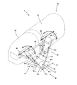
図3は、左側のアームレスト4の側面図であり、主に前側ユニット60及び後側ユニット61を移動させる駆動機構65の構成を模式的に示している。また、図4は、図3に示す駆動機構65の模式的な正面図である。
[Configuration of armrest]
FIG. 3 is a side view of the
図3に示すように、アームレスト4の下部に位置するサイドカバー21内には駆動機構65が収容されており、この駆動機構65は、前後に配設された前側リンク71及び後側リンク72と、各リンク71,72に対応して設けられた2つの空気袋73,74とを有している。これらのリンク71,72及び空気袋73,74は、本実施の形態において前側ユニット60及び後側ユニット61を前後方向へ付勢する付勢手段を成している。
As shown in FIG. 3, a
前側リンク71は上下方向に長寸であって、図4に示すように下部71aが平板状を成し、上部は左右に分かれた二股状を成して上方へ延びる左右の上端部71b,71bを有している。前側リンク71の下部71aは、サイドカバー21内に形成された略水平を成すリンク支持面70にて、左右方向の枢軸70aにより支持されており、この枢軸70aを中心として上端部71bが前後方向へ揺動可能になっている。また、上端部71b,71bには、リンク71の長手方向に沿って延びる長円形状の係合孔71cが、左右方向に貫通して形成されている。
The
同様に、後側リンク72も上下方向に長寸であって下部72aが平板状を成し、上部は左右に分かれた二股状を成して上方へ延びる左右の上端部72b,72bを有している。後側リンク72の下部72aは上記前側リンク71の下部71aを支持するのと同じ枢軸70aにより支持されており、この枢軸70aを中心として上端部72bが前後方向へ揺動可能になっている。また、上端部72b,72bには、後側リンク72の長手方向に沿って延びる長円形状の係合孔72cが、左右方向に貫通して形成されている。
Similarly, the
2つの空気袋73,74のうち一方の空気袋74は、リンク支持面70と後側リンク72の下部72aとの間に設けられており、他方の空気袋73は、前後の各リンク71,72の下部71a,72aの間に設けられている。これらの空気袋73,74は何れも、展開不能な基端部73a,74aと展開可能な展開部73b,74bとを有し、給気されることによって基端部73a,74aを中心として展開部73b,74bが展開して扇状に膨張するように構成されている。そして、何れの空気袋73,74も、その基端部73a,74aが展開部73b,74bに比べて枢軸70aに近接するようにして配設されている。従って、後側の空気袋74が膨張すると、前後のリンク71,72は何れも前方へ揺動し、前側の空気袋73が膨張すると、前側リンク71のみが更に前方へ揺動するようになっている。なお、図2に示すように、これらの空気袋73,74は給排気装置51にエアチューブを介して接続されており、制御部50からの指示で給排気装置51が駆動することにより、互いに独立して給排気され、膨張及び収縮するようになっている。
One of the two
また、図3に示すように、前側の空気袋73と後側リンク72の下部72aとの間には圧力センサ60aが設けられ、後側の空気袋74とリンク支持面70との間には別の圧力センサ61aが設けられている。図2に示すように、これらの圧力センサ60a,61aは制御部50に接続されており、所定の圧力が付与されたときに、所定の信号を制御部50へ出力するように構成されている。
Further, as shown in FIG. 3, a
一方、前側ユニット60の下部には前側ユニット支持部75が設けられ、後側ユニット61の下部には後側ユニット支持部76が設けられている。図4に示すように、前側ユニット支持部75は正面視で上方へ開いた略U字状を成すと共に前端と後端とが開口した形状となっており、底壁部75aと左右の側壁部75bとを有している。左右の側壁部75bは、前側リンク71の左右の上端部71bに対して所定のスペース75sを隔てて内方に位置しており、左右の側壁部75bの上端部は前側ユニット60の底部に固定されている。また、左右の側壁部75bからは、外側方へ向けて係合突起75cが突設されている。この係合突起75cは、前側リンク71の上端部71bに形成された係合孔71cに挿通されている。
On the other hand, a
同様に、後側ユニット支持部76も正面視で上方へ開いた略U字状を成すと共に前端と後端とが開口した形状となっており、底壁部76aと左右の側壁部76bとを有している。左右の側壁部76bは、後側リンク72の左右の上端部72bに対して所定のスペース(図示せず)を隔てて内方に位置しており、左右の側壁部76bの上端部は後側ユニット61の底部に固定されている。また、左右の側壁部76bからは、外側方へ向けて係合突起76cが突設されており、この係合突起76cは、後側リンク72の上端部72bに形成された係合孔72cに挿通されている。なお、後側ユニット支持部76及びこれが有する上記底壁部76a、側壁部76b、係合突起76cなどは、前側ユニット支持部75の対応する部分と同様の構成となっているため、図4では、前側ユニット支持部75において対応する部分に後側ユニット支持部76の対応する部分の符号を括弧書きで示している。
Similarly, the rear
また、前側ユニット支持部75の底壁部75a及び後側ユニット支持部76の底壁部76aには、軸芯を一致させて前後方向へ貫通する矩形断面の貫通孔77が形成されている。この貫通孔77には、前後方向へ延設されて貫通孔77の断面形状に略整合する矩形断面を有する揺動シャフト78が挿通されており、前側ユニット支持部75及び後側ユニット支持部76は、貫通孔77に揺動シャフト78が挿通された状態で、該揺動シャフト78に沿って前後方向へスライド可能になっている。また、揺動シャフト78の前端は、サイドカバー21内に設けられた軸受部79によって、軸芯回りへの回転が自在なようにして支持されており、後端部は、サイドカバー21内に設けられたモータ80の出力軸に対してギヤボックス81を介して接続されている。そして、モータ80が回転駆動すると、その回転力がギヤボックス81を介して伝達され、揺動シャフト78は軸芯回りに回転可能になっている。なお、図2に示すように、このモータ80は駆動部54を介して制御部50に接続されており、制御部50からの指示で駆動部54が動作することによって所望の速度で所望の角度だけ回転できるようになっている。
Further, a through-hole 77 having a rectangular cross section is formed in the
また、後側ユニット61の底部には前後方向へ延びる板状のガイドプレート82の後部が接続されている。このガイドプレート82は、後側ユニット支持部76が有する左右の側壁部76b,76bの間に位置しており、且つ、これらの側壁部76b,76bの離隔距離より若干小さい幅寸法を有するように構成されている。そして、ガイドプレート82の前部は、前側ユニット60の下方へ、前側ユニット支持部75が有する左右の側壁部75b,75bの間を通るように延設されている。従って、前側ユニット60と後側ユニット61とは、相対的に前後動する際にこのガイドプレート82に沿って移動することとなり、左右方向の位置ズレが規制される。なお、ガイドプレート82は、上腕ユニット62(図3参照)の底部付近から前方へ延設するように設け、前側ユニット支持部75の側壁部75b,75b間、及び後側ユニット支持部76の側壁部76b,76b間を通るように構成されていてもよい。
A rear portion of a plate-shaped
更に、前側ユニット60の後端部と、後側ユニット61の前端部及び後端部と、上腕ユニット62の前端部とには、夫々クッション材85が取り付けられている。
Further,
[前側ユニット及び後側ユニットの動作]
次に、このような構成を備えるアームレスト4の動作について説明する。まず、後側の空気袋74のみへ給排気した場合、枢軸70aを中心として後側リンク72が前後方向へ揺動し、これに伴って後側ユニット支持部76と共に後側ユニット61が前後方向へスライドする。また同時に、前側リンク71も前後方向へ揺動するため、これに伴って前側ユニット支持部75と共に前側ユニット60も前後方向へスライドする。これに対し、前側の空気袋73のみへ給排気した場合は、前側リンク71のみが前後方向へ揺動するため、前側ユニット60のみが前後方向へスライドする。このとき、後側の空気袋74の膨張状態が維持しておくか又は完全に収縮した状態を維持し、前側の空気袋73の膨張・収縮に伴って後側リンク72が前後方向へ揺動しないようにしておくことにより、前側ユニット60のみを前後方向へスライドさせることができる。また、前側の空気袋73を排気しつつ後側の空気袋74へ給気することにより後側ユニット61のみを前方へスライドさせることができ、逆に前側の空気袋73へ給気しつつ後側の空気袋74を排気することにより後側ユニット61のみを後方へスライドさせることもできる。更に、前後の空気袋73,74への給排気の量、速度、タイミングを適宜調整することにより、前側ユニット60と後側ユニット61とを、互いの可動範囲内において多様なパターンで前後方向へスライドさせることができる。
[Operation of front unit and rear unit]
Next, operation | movement of the
また、これに合わせてエアセル7d〜7hの一部又は複数へ給気してこれらを膨張させると、被施療者の腕部に対して、腕部の長手方向へのストレッチや擦りマッサージを施すことができる。例えば、エアセル7d,7e,7fを膨張させて手及び前腕を保持しつつ、前側ユニット60と後側ユニット61とを相対的に離反させるように空気袋73,74へ給排気を行うと、手と前腕とを互いに引き離すようにストレッチすることができる。また、エアセル7e,7fを膨張させた状態で後側ユニット61を前後方向へ移動させることにより、前腕に対して前後方向へ擦るようにマッサージすることができる。
In addition, when a part or a plurality of
この擦りマッサージをする場合においては、前側ユニット60のエアセル7dを膨張させて手を保持した状態とするか、上腕ユニット62のエアセル7g,7hを膨張させて上腕を保持した状態とすることにより、後側ユニット61の移動に伴う前腕の位置ズレを抑制でき、効果的な施療を実現することができる。同様に、前側ユニット60を前後へスライドさせて手及び手首を擦りマッサージする場合も、後側ユニット61のエアセル7e,7fを膨張させて前腕を保持することにより、位置ズレを抑制して効果的に擦りマッサージを施すことができる。更に、擦りマッサージをする際には、位置ズレ防止のために膨張させるエアセルへの給気量に比べて、施療部位に接触させるエアセルへの給気量を若干少なめにしておくことにより、効果的に擦りマッサージを実現することができる。
In the case of this rubbing massage, the
一方、モータ80を回転駆動させると、その回転力がギヤボックス81を介して揺動シャフト78に伝達され、該揺動シャフト78の回動に伴って、前側ユニット支持部75と共に前側ユニット60が左右方向へ揺動し、後側ユニット支持部76と共に後側ユニット61が左右方向へ揺動する。
On the other hand, when the
また、これに合わせてエアセル7d〜7hの一部又は複数を膨張させることにより、被施療者の腕部に対して、腕部の周方向への捻りマッサージや擦りマッサージを施すことができる。例えば、エアセル7d〜7hを膨張させて手及び前腕と上腕とを保持しつつ、前側ユニット60及び後側ユニット61を左右へ揺動させると、固定的に保持されている上腕に対して、手及び前腕が揺動され、腕部の周方向へ捻るようなマッサージを実現することができる。また、エアセル7d,7e,7fを膨張させた状態で前側ユニット60及び後側ユニット61を左右へ揺動させると、手及び前腕の表面を周方向へ擦るようにマッサージすることができる。この擦りマッサージにおいては、上腕ユニット62のエアセル7g,7hを膨張させて上腕を保持した状態とすることにより、前側ユニット60及び後側ユニット61の揺動に伴う手及び前腕の位置ズレを抑制でき、効果的な施療を実現することができる。更に、擦りマッサージにおいては、位置ズレ防止のために膨張させるエアセル7g,7hへの給気量に比べて、施療部位に接触させるエアセル7d,7e,7fへの給気量を若干少なめにしておくことにより、効果的に擦りマッサージを実現することができる。
In addition, by inflating a part or a plurality of the
更に、前側ユニット60及び後側ユニット61の前後スライド動作及び左右揺動動作は、制御部50によって制御されて同時に行うこともできるため、更に多様なマッサージを実現することもできる。例えば、エアセル7d,7e,7fを膨張して手及び前腕を保持した状態で、前側ユニット60及び後側ユニット61を互いに離反させつつ左右へ揺動させることにより、手及び前腕をストレッチしながら捻りマッサージを施すことができる。また、これらの施療パターンを任意に組み合わせることができ、例えば、腕部の長手方向及び/又は周方向への擦りマッサージを行って筋肉をほぐした後に、ストレッチ及び/又は捻りマッサージを施すことも可能である。
Furthermore, since the front-rear slide operation and the left-right swinging operation of the
なお、前側ユニット支持部75の係合突起75cは前側リンク71が有して長円形状を成す係合孔71cに挿通されているため、この係合孔71c内を係合突起75cが移動できる範囲内で前側ユニット60は揺動可能になっている。また、前側ユニット支持部75の左右の側壁部75bと前側リンク71の上端部71bとの間にはスペース75sが設けられているため、前側ユニット支持部75が左右に揺動する際に前側リンク71の上端部71bと接触しないようになっている。後側ユニット61についても同様である。
Note that the
また、前側ユニット60と後側ユニット61との対向箇所にはクッション材85が取り付けられているため、両ユニット60,61間に異物が挟み込まれた場合に、これによって両ユニット60,61が損傷するのを防止できる。同様に、後側ユニット61と上腕ユニット62との対向箇所にもクッション材85が取り付けられているため、両ユニット61,62間に異物が挟み込まれた場合にも、これによって両ユニット61,62が損傷するのを防止できる。また、前側の空気袋73と後側リンク72の下部72aとの間には圧力センサ60aが設けられているため、この間の圧力を取得することにより、前側ユニット60の前方移動に対する抵抗の有無を検出することができる。従って、これに基づいて前側ユニット60が可動範囲の前端に到達したことなどを検出することができ、空気袋73への給気を停止するタイミングを計ることができる。また、後側の空気袋74とリンク支持面70との間には別の圧力センサ61aが設けられているため、この間の圧力を取得することにより、後側ユニット61の前方移動に対する抵抗の有無を検出することができる。従って、これに基づいて後側ユニット61が可動範囲の前端に到達したことや、前側ユニット60と接触したことなどを検出することができ、空気袋74への給気を停止するタイミングを計ることができる。
Moreover, since the
なお、前側リンク71と後側リンク72に対し、空気袋73,74が収縮する方向へ付勢するスプリングコイル等の付勢部を設けても良い。また、前側リンク71と後側リンク72とを同一の枢軸70aによって支持した構成を示したが、両者を前後に離隔して配置した別々の枢軸によって支持するようにしてもよい。
In addition, you may provide urging | biasing parts, such as a spring coil which urges | biases the
[アームレストの他の構成(1)]
図5は、アームレスト4の他の構成を示す斜視図であり、アームレスト4の一部を模式的に示している。また、図6は、図5に示すアームレスト4を採用した椅子型マッサージ機1の機能的構成を示すブロック図であり、図2に示した構成と共通する部分には同一の符号を付して示している。図5に示すように、このアームレスト4が備える駆動機構90は、前側リンク91及び後側リンク92と、両リンク91,92間に設けられた前側の空気袋93と、後側リンク92及びリンク支持面70の間に設けられた後側の空気袋94とを備えており、これらのリンク91,92及び空気袋93,94は、本実施の形態において前側ユニット60及び後側ユニット61を前後方向及び左右方向へ付勢する付勢手段を成している。
[Other configuration of armrest (1)]
FIG. 5 is a perspective view showing another configuration of the
前側リンク91は、下部91aが矩形板状を成し、その下端部が左右方向の枢軸70aによって支持されており、その上端部の左右には上方へ延びる2本のエアシリンダ91b,91bがジョイント97,97を介して接続されている。このエアシリンダ91bは給排気装置51(図6参照)にエアチューブを介して接続されており、該給排気装置51からの給排気によって所定範囲内で伸縮自在となっており、且つ、その範囲内の任意の長さ寸法で伸縮不能なようにロック可能となっている。そして、両エアシリンダ91b,91bの上端部は、別のジョイント98,98を介して、前側ユニット60の下部に取り付けられた前側ユニット支持部95の左右の部分に接続されている。
The
なお、ジョイント97は下部91aに対してエアシリンダ91bが三次元的に揺動することを許容する自在継手であり、且つ、所定の基本姿勢(ここでは、下部91aから上方へ延びる姿勢)へ復帰するようにエアシリンダ91bを付勢し得る構成となっており、例えば、所定の弾性を有するゴム等の合成樹脂やコイルスプリングなどで構成される。もう一つのジョイント98も自在継手(ユニバーサルジョイント)であり、こちらは比較的に動作抵抗が小さく、エアシリンダ91bと前側ユニット支持部95とは比較的容易に相対姿勢が変更され得るような構成となっている。
The joint 97 is a universal joint that allows the
同様に、後側リンク92は、下部92aが矩形板状を成し、その下端部が前側リンク91の下部91aを枢支するものと同じ枢軸70aによって支持されており、その上端部の左右には上方へ延びる2本のエアシリンダ92b,92bがジョイント97,97を介して接続されている。このエアシリンダ92bは給排気装置51(図6参照)にエアチューブを介して接続されており、該給排気装置51からの給排気によって所定範囲内で伸縮自在となっており、且つ、その範囲内の任意の長さ寸法で伸縮不能なようにロック可能となっている。そして、両エアシリンダ92b,92bの上端部は、別のジョイント98,98を介して、後側ユニット61の下部に取り付けられた後側ユニット支持部96の左右の部分に接続されている。
Similarly, the
なお、上記前側ユニット支持部95及び後側ユニット支持部96は、図3及び図4に示した前側ユニット支持部75及び後側ユニット支持部76のように略U字状であってもよいが、ここでは平面視矩形状の板部材から成るものを示している。そして、これらの前側ユニット支持部95及び後側ユニット支持部96には、前後方向へ延びるガイドロッド99が挿通されている。ガイドロッド99は断面円形をしており、両ユニット支持部95,96はこのガイドロッド99の周りに回動可能(即ち、左右方向へ揺動可能)に支持されている。
The front
また、前側の空気袋93は、前側リンク91及び後側リンク92の間において、両リンク91,92が有する矩形板状の下部91a,92aに挟まれて設けられており、図3に示す空気袋73と同様の基端部93a及び展開部93bを有して扇状に膨張可能に構成され、且つ空気袋73と同様に基端部93aが展開部93bに比べて枢軸70aに近接するように配設されている。後側の空気袋94は、後側リンク92の下部92aとリンク支持面70との間に挟まれるようにして設けられており、図3に示す空気袋74と同様に、基端部94a及び展開部94bを有して扇状に膨張可能に構成され、且つ空気袋74と同様に基端部94aが展開部94bに比べて枢軸70aに近接するように配設されている。そして、これらの空気袋93,94も給排気装置51(図6参照)にエアチューブを介して接続されており、該給排気装置51からの給排気によって膨張及び収縮可能になっている。
Further, the
このような構成のアームレスト4の場合、エアシリンダ91b,92b及び空気袋93,94への給排気を適宜調整することにより、前側ユニット60及び後側ユニット61を、互いに独立して前後スライド動作及び左右揺動動作させることが可能であり、しかも、前後スライド動作と左右揺動動作を同時に実行することもできる。
In the case of the
例えば、空気袋94を膨張及び収縮させることによって、前側ユニット60及び後側ユニット61を前後方向へスライドさせることができ、空気袋93を膨張及び収縮させることによって、前側ユニット60のみを前後方向へスライドさせることができる。また、空気袋93を排気しつつ空気袋94へ給気することにより後側ユニット61のみを前方へスライドでき、逆に空気袋93へ給気しつつ空気袋94を排気することにより後側ユニット61のみを後方へスライドさせることもできる。
For example, by inflating and deflating the
また、前側ユニット60に関していえば、これに対応する前側リンク91の左右のエアシリンダ91b,91bを適宜伸縮させることにより、前側ユニット60を左右方向へ揺動させることができる。また、左右のシリンダ91b,91bのうち一方を所定長にロックしておき、他方を伸縮自在なフリーの状態とし、この状態で空気袋93,94へ給排気することにより、前側ユニット60を前後方向へスライドさせつつ左右へ揺動させることができる。即ち、右側のシリンダ91bをロックし左側のシリンダ91bをフリーとした状態で空気袋93,94を膨張させると、前側ユニット60は前方へスライドしつつ、ロックされたシリンダ91bがある右側部分が下方へ向かうように揺動させることができ、空気袋93,94を収縮させた場合はこの逆の動作となる。反対に、左側のシリンダ91bをロックし右側のシリンダ91bをフリーとした状態で空気袋93,94を膨張させると、前側ユニット60は前方へスライドしつつ、ロックされたシリンダ91bがある左側部分が下方へ向かうように揺動させることができ、空気袋93,94を収縮させた場合はこの逆の動作となる。
As for the
なお、後側ユニット61に関しても同様であり、前方へスライドさせつつ、右側部分又は左側部分が下方へ向かうように揺動させることができ、後方へスライドさせつつ、右側部分又は左側部分が下方へ向かうように揺動させることができる。
The same applies to the
[アームレストの他の構成(2)]
図7は、アームレスト4の更に他の構成を示す斜視図であり、アームレスト4が備える前側ユニット60を動作させる態様を模式的に示している。図7に示す駆動機構100は、固定長を有して左右に配設された2本のリンクロッド101,102を有している。このうち右側のリンクロッド101は、上端部がボールジョイント103を介して前側ユニット支持部95の右側部分に接続され、下端部もボールジョイント103を介してリンク支持面70の右側部分に接続されている。左側のリンクロッド102は、上端部がボールジョイント103を介して前側ユニット支持部95の左側部分に接続されており、下端部もボールジョイント103を介してリンク支持面70の左側部分に接続されている。但し、各リンクロッド101,102と前側ユニット支持部95との接続位置は、その前後方向位置が略同一となるように横並びに配設されているが、各リンクロッド101,102とリンク支持面70との接続位置は、前後方向に所定距離ずらされて配設されており、本実施の形態では右側のリンクロッド101の下端部は左側のリンクロッド102の下端部よりも前方に位置している。
[Other configuration of armrest (2)]
FIG. 7 is a perspective view showing still another configuration of the
なお、図7に示す駆動機構100は、これらのリンクロッド101,102の他にも、既に説明した駆動機構65,90と同様の空気袋(図示せず)を有し、リンクロッド101,102を前後方向へ揺動可能な構成となっており、このようなリンクロッド101,102と空気袋とによって、前側ユニット60を移動させる付勢手段を成している。また、図示は省略しているが、前側ユニット支持部95には図5に示したのと同様のガイドロッドが挿通されており、該ガイドロッドに支持された状態で左右へ揺動可能になっている。また、後側ユニット61を移動させる構成についても、上記前側ユニット60を移動させる構成と同様であるため、ここでの詳細な説明は省略する。
In addition to the
このような構成を備えるアームレスト4では、図示しない空気袋を膨張及び収縮させ、リンクロッド101,102を前後方向へ揺動させると、前側ユニット60を前後方向へスライドさせることができる。しかも、各リンクロッド101,102が固定長であり、且つ下端部のリンク支持面70への接続位置が前後方向にずらされているため、前後方向へのスライドに伴って前側ユニット60は左右方向へも揺動させられることとなる。本実施の形態のように、右側のリンクロッド101の下端部を左側のリンクロッド102の下端部より前方でリンク支持面70に接続した場合、前側ユニット60は前方へスライドしつつ左側部分が下方へ向かうように揺動し、後方へスライドさせると右側部分が下方へ向かうように揺動することとなる。逆に、左側のリンクロッド102の下端部を右側のリンクロッド101の下端部より前方でリンク支持面70に接続した場合、前側ユニット60は前方へスライドしつつ右側部分が下方へ向かうように揺動し、後方へスライドさせると左側部分が下方へ向かうように揺動することとなる。
In the
また、リンクロッド101,102と前側ユニット支持部95とは図7に示したような接続形態の他、図8に示すような接続形態としてもよい。具体的には、左右のリンクロッド101,102の下端部を、前後方向位置が同じになるように配置させてリンク支持面70に接続する一方、各リンク101,102の上端部の前後方向位置を異ならせた状態で前側ユニット支持部95に接続するようにしてもよく、図8では、左側のリンクロッド102の上端部に比べて右側のリンクロッド101の上端部の方が前方に位置する状態で、前側ユニット支持部95に夫々接続されている。このような構成によっても、前側ユニット60の前後動に伴ってこれを左右へ揺動させることができる。
Further, the
[アームレストの他の構成(3)]
図9は、アームレスト4の更に他の構成を示す模式的平面図であり、前側ユニット60及び後側ユニット61が相対的に後方に位置する状態(収縮状態)を二点鎖線で、相対的に前方に位置する状態(伸長状態)を太い実線で夫々示している。このアームレスト4は、前側ユニット60及び後側ユニット61の下方に伸縮機構110が備えられており、これらのユニット60,61はこの伸縮機構110に支持されている。より詳しく説明すると、伸縮機構110は前後方向へ伸縮可能なパンタグラフ構造を成しており、その後端部110cは上腕ユニット62の下部に支持され、前端部110aは前側ユニット60の下部に支持され、更に、前端部110aと後端部110cとの間の中間部110bが後側ユニット61の下部に支持されている。なお、伸縮機構110についても、収縮状態を二点鎖線で示し、伸長状態を太い実線で示している。
[Other configuration of armrest (3)]
FIG. 9 is a schematic plan view showing still another configuration of the
また、上腕ユニット62の左右からは、前方へ向けて2本のガイドレール111が延設されており、前側ユニット60及び後側ユニット61は、このガイドレール111に沿って前後方向へスライド可能であると共に、左右方向への位置ズレが規制されるようになっている。そして、後側ユニット61の下方には、図示しない駆動用の空気袋が配設されており、図2に示すものと同様の給排気装置から給排気することによって膨張・収縮し、後側ユニット61を前後方向へ付勢可能となっている。
Further, two
このようなアームレスト4は、前記空気袋に給排気すると、後側ユニット61が前後方向へスライド移動すると共に、伸縮機構110を介して連結された前側ユニット60も同様に前後方向へスライド移動する。また、上述したように、伸縮機構110はパンタグラフ構造になっていて後端部110cが上側ユニット62に支持されているため、後側ユニット61のスライド距離に比例して、それより大きな距離だけ前側ユニット60を同方向へスライドさせることができる。しかも、両ユニット60,61をスライドさせるに際し、後側ユニット61を移動させる上記空気袋のみへの給排気で済むという利点もある。
When such an
なお、以上の説明では肘置き部20を、前側ユニット60と後側ユニット61と上腕ユニット62とに3分割し、そのうち前側ユニット60及び後側ユニット61を前後方向及び左右方向へ移動させる構成について説明したが、上腕ユニット62についても前後方向及び左右方向へ移動させるようにしてもよいし、肘置き部20を2分割又は4分割以上としてもよい。また、上記前側ユニット60及び後側ユニット61を一体構造とし、これを前後方向へのスライド移動、及び/又は左右方向へ揺動が可能なようにしてもよい。
In the above description, the
本発明は、被施療者の体格に応じて肘置き部を容易に位置変更することができ、また、腕部に対して多様なマッサージを施すことができる椅子型マッサージ機に適用することができる。 INDUSTRIAL APPLICABILITY The present invention can be applied to a chair type massage machine that can easily change the position of the elbow rest according to the physique of the user and can perform various massages on the arm. .
1 椅子型マッサージ機
2 座部
3 背凭れ部
4 アームレスト
5 フットレスト
20 肘置き部
21 サイドカバー
7 エアセル
50 制御部
51 給排気装置
60 前側ユニット
60a 圧力センサ
61 後側ユニット
61a 圧力センサ
62 上腕ユニット
65,90,100 駆動機構
71,91 前側リンク
72,92 後側リンク
73,74,93,94 空気袋
78 揺動シャフト
80 モータ
85 クッション材
101,102 リンクロッド
DESCRIPTION OF
Claims (7)
該肘置き部は、
載置された被施療者の腕部のうち手先側の部位を支持する前側ユニットと、
前記手先側の部位より相対的に肩側寄りに位置する部位を支持する後側ユニットと、
前記前側ユニット及び後側ユニットに設けられた被施療者の腕部を保持すべく膨縮する空気袋と、
前記前側ユニット及び後側ユニットを移動させる駆動ユニットを有し、
前記駆動ユニットと前記前側ユニットの空気袋及び後側ユニットの空気袋は、制御部によって、それぞれ駆動され、
前記前側ユニット及び後側ユニットは、独立して前後方向へ移動することを特徴とする椅子型マッサージ機。 A chair-type massage machine including a seat portion on which a user is seated, wherein an armrest portion on which the arm portion of the user is placed is disposed on the left and right sides of the seat portion,
The elbow rest is
A front unit that supports a hand-side portion of the arm of the user being placed;
A rear unit that supports a portion located closer to the shoulder side than the hand side portion;
An air bag inflated and inflated to hold the arm of the user provided in the front unit and the rear unit;
A driving unit for moving the front unit and the rear unit ;
The drive unit and the air bag of the front unit and the air bag of the rear unit are respectively driven by the control unit,
The chair type massage machine, wherein the front unit and the rear unit move independently in the front-rear direction.
Priority Applications (3)
| Application Number | Priority Date | Filing Date | Title |
|---|---|---|---|
| JP2008139856A JP5042923B2 (en) | 2008-05-28 | 2008-05-28 | Chair type massage machine |
| PCT/JP2008/001882 WO2009013870A1 (en) | 2007-07-24 | 2008-07-14 | Chair type massage machine |
| CN200880025038.7A CN101754740B (en) | 2007-07-24 | 2008-07-14 | Chair type massage machine |
Applications Claiming Priority (1)
| Application Number | Priority Date | Filing Date | Title |
|---|---|---|---|
| JP2008139856A JP5042923B2 (en) | 2008-05-28 | 2008-05-28 | Chair type massage machine |
Publications (3)
| Publication Number | Publication Date |
|---|---|
| JP2009285074A JP2009285074A (en) | 2009-12-10 |
| JP2009285074A5 JP2009285074A5 (en) | 2012-05-24 |
| JP5042923B2 true JP5042923B2 (en) | 2012-10-03 |
Family
ID=41454871
Family Applications (1)
| Application Number | Title | Priority Date | Filing Date |
|---|---|---|---|
| JP2008139856A Active JP5042923B2 (en) | 2007-07-24 | 2008-05-28 | Chair type massage machine |
Country Status (1)
| Country | Link |
|---|---|
| JP (1) | JP5042923B2 (en) |
Cited By (1)
| Publication number | Priority date | Publication date | Assignee | Title |
|---|---|---|---|---|
| CN103784227A (en) * | 2014-01-13 | 2014-05-14 | 天津市康颐医疗用品科技有限公司 | Novel integral comprehensive health recuperating treatment cabin |
Families Citing this family (5)
| Publication number | Priority date | Publication date | Assignee | Title |
|---|---|---|---|---|
| KR102506570B1 (en) * | 2015-12-09 | 2023-03-06 | 코웨이 주식회사 | Method for operating a Kegel exercise mode in a massage chair and the massage chair capable of using the same |
| JP6765354B2 (en) * | 2017-08-07 | 2020-10-07 | 株式会社フジ医療器 | Massage machine |
| KR102287897B1 (en) * | 2017-08-17 | 2021-08-09 | 코웨이 주식회사 | Massage chair that can massage blood spots of lower body |
| JP7330523B2 (en) * | 2021-03-05 | 2023-08-22 | 大東電機工業株式会社 | massager |
| CN116637010B (en) * | 2023-06-25 | 2024-02-02 | 连云港天诺光学仪器有限公司 | Air pressure wave therapeutic instrument's governing system |
Family Cites Families (9)
| Publication number | Priority date | Publication date | Assignee | Title |
|---|---|---|---|---|
| JPH1042999A (en) * | 1996-08-01 | 1998-02-17 | Chitose Kk | Armrest structure for chair |
| JPH10243981A (en) * | 1997-03-05 | 1998-09-14 | Fuji Iryoki:Kk | Air pressure massage machine for arms |
| JP3388151B2 (en) * | 1997-09-03 | 2003-03-17 | 日東工器株式会社 | Compression device for pneumatic massager |
| JP4056285B2 (en) * | 2002-04-19 | 2008-03-05 | ファミリー株式会社 | Massage machine |
| JP4153841B2 (en) * | 2002-12-12 | 2008-09-24 | ファミリー株式会社 | Massage machine |
| JP4563673B2 (en) * | 2003-12-26 | 2010-10-13 | 株式会社フジ医療器 | Massage machine |
| JP4274019B2 (en) * | 2004-03-26 | 2009-06-03 | パナソニック電工株式会社 | Chair massage machine |
| JP4388432B2 (en) * | 2004-07-23 | 2009-12-24 | 株式会社フジ医療器 | Limb body massage device |
| JP4779637B2 (en) * | 2005-12-20 | 2011-09-28 | パナソニック電工株式会社 | Massage chair |
-
2008
- 2008-05-28 JP JP2008139856A patent/JP5042923B2/en active Active
Cited By (1)
| Publication number | Priority date | Publication date | Assignee | Title |
|---|---|---|---|---|
| CN103784227A (en) * | 2014-01-13 | 2014-05-14 | 天津市康颐医疗用品科技有限公司 | Novel integral comprehensive health recuperating treatment cabin |
Also Published As
| Publication number | Publication date |
|---|---|
| JP2009285074A (en) | 2009-12-10 |
Similar Documents
| Publication | Publication Date | Title |
|---|---|---|
| JP4943202B2 (en) | Chair massage machine | |
| JP4651556B2 (en) | Massage machine | |
| JP5042923B2 (en) | Chair type massage machine | |
| TW201235030A (en) | Massage machine | |
| JP2003310683A (en) | Massage machine | |
| JP2009112790A (en) | Chair type massage machine | |
| JP4917358B2 (en) | Treatment machine | |
| JP2008200343A (en) | Chair type massage machine | |
| JP3854944B2 (en) | Chair type massage machine | |
| JP5555209B2 (en) | Oscillator | |
| TWI402062B (en) | Massage machine | |
| CN101754740B (en) | Chair type massage machine | |
| JP5060101B2 (en) | Massage machine | |
| JP5010960B2 (en) | Massage machine | |
| JP4078676B2 (en) | Chair type massage device | |
| JP2009028087A (en) | Chair type massage machine | |
| JP4789739B2 (en) | Chair type massage machine | |
| JP5575732B2 (en) | Chair massage machine | |
| JP3631885B2 (en) | Chair type air massage machine | |
| JP5563548B2 (en) | Massage machine | |
| JP2001333952A (en) | Massage machine | |
| JP3998507B2 (en) | Massage machine | |
| JP5306173B2 (en) | Massage machine | |
| JP5306164B2 (en) | Massage machine | |
| JP2003164503A (en) | Massager |
Legal Events
| Date | Code | Title | Description |
|---|---|---|---|
| A621 | Written request for application examination |
Free format text: JAPANESE INTERMEDIATE CODE: A621 Effective date: 20101206 |
|
| A521 | Request for written amendment filed |
Free format text: JAPANESE INTERMEDIATE CODE: A523 Effective date: 20111206 |
|
| RD05 | Notification of revocation of power of attorney |
Free format text: JAPANESE INTERMEDIATE CODE: A7425 Effective date: 20111212 |
|
| A521 | Request for written amendment filed |
Free format text: JAPANESE INTERMEDIATE CODE: A523 Effective date: 20120330 |
|
| TRDD | Decision of grant or rejection written | ||
| A01 | Written decision to grant a patent or to grant a registration (utility model) |
Free format text: JAPANESE INTERMEDIATE CODE: A01 Effective date: 20120702 |
|
| A01 | Written decision to grant a patent or to grant a registration (utility model) |
Free format text: JAPANESE INTERMEDIATE CODE: A01 |
|
| A61 | First payment of annual fees (during grant procedure) |
Free format text: JAPANESE INTERMEDIATE CODE: A61 Effective date: 20120711 |
|
| R150 | Certificate of patent or registration of utility model |
Free format text: JAPANESE INTERMEDIATE CODE: R150 Ref document number: 5042923 Country of ref document: JP Free format text: JAPANESE INTERMEDIATE CODE: R150 |
|
| FPAY | Renewal fee payment (event date is renewal date of database) |
Free format text: PAYMENT UNTIL: 20150720 Year of fee payment: 3 |
|
| FPAY | Renewal fee payment (event date is renewal date of database) |
Free format text: PAYMENT UNTIL: 20150720 Year of fee payment: 3 |
|
| S533 | Written request for registration of change of name |
Free format text: JAPANESE INTERMEDIATE CODE: R313533 |
|
| R350 | Written notification of registration of transfer |
Free format text: JAPANESE INTERMEDIATE CODE: R350 |
|
| R250 | Receipt of annual fees |
Free format text: JAPANESE INTERMEDIATE CODE: R250 |
|
| R250 | Receipt of annual fees |
Free format text: JAPANESE INTERMEDIATE CODE: R250 |
|
| R250 | Receipt of annual fees |
Free format text: JAPANESE INTERMEDIATE CODE: R250 |
|
| R250 | Receipt of annual fees |
Free format text: JAPANESE INTERMEDIATE CODE: R250 |
|
| R250 | Receipt of annual fees |
Free format text: JAPANESE INTERMEDIATE CODE: R250 |
|
| R250 | Receipt of annual fees |
Free format text: JAPANESE INTERMEDIATE CODE: R250 |
|
| R250 | Receipt of annual fees |
Free format text: JAPANESE INTERMEDIATE CODE: R250 |
|
| R250 | Receipt of annual fees |
Free format text: JAPANESE INTERMEDIATE CODE: R250 |
|
| R250 | Receipt of annual fees |
Free format text: JAPANESE INTERMEDIATE CODE: R250 |