JP4078676B2 - Chair type massage device - Google Patents

Chair type massage device Download PDF

Info

Publication number
JP4078676B2
JP4078676B2 JP2005362956A JP2005362956A JP4078676B2 JP 4078676 B2 JP4078676 B2 JP 4078676B2 JP 2005362956 A JP2005362956 A JP 2005362956A JP 2005362956 A JP2005362956 A JP 2005362956A JP 4078676 B2 JP4078676 B2 JP 4078676B2
Authority
JP
Japan
Prior art keywords
user
heel
type massage
chair
support
Prior art date
Legal status (The legal status is an assumption and is not a legal conclusion. Google has not performed a legal analysis and makes no representation as to the accuracy of the status listed.)
Expired - Fee Related
Application number
JP2005362956A
Other languages
Japanese (ja)
Other versions
JP2006087945A (en
Inventor
二千武 稲田
Current Assignee (The listed assignees may be inaccurate. Google has not performed a legal analysis and makes no representation or warranty as to the accuracy of the list.)
Family Inada Co Ltd
Original Assignee
Family Inada Co Ltd
Priority date (The priority date is an assumption and is not a legal conclusion. Google has not performed a legal analysis and makes no representation as to the accuracy of the date listed.)
Filing date
Publication date
Application filed by Family Inada Co Ltd filed Critical Family Inada Co Ltd
Priority to JP2005362956A priority Critical patent/JP4078676B2/en
Publication of JP2006087945A publication Critical patent/JP2006087945A/en
Application granted granted Critical
Publication of JP4078676B2 publication Critical patent/JP4078676B2/en
Anticipated expiration legal-status Critical
Expired - Fee Related legal-status Critical Current

Links

Images

Landscapes

  • Finger-Pressure Massage (AREA)
  • Percussion Or Vibration Massage (AREA)
  • Massaging Devices (AREA)

Description

本発明は、座部及びフットレストを有して被施療者の脚部を施療する椅子型マッサージ装置に関し、特に被施療者の踵を施療するフットレストを有する椅子型マッサージ装置に関する。   The present invention relates to a chair type massage apparatus having a seat part and a footrest and treating a leg part of a user, and more particularly to a chair type massage apparatus having a footrest to treat a patient's heel.

従来の椅子型マッサージ装置の多くは、主として被施療者の背中及び肩に対して押圧刺激を与える構成となっている。しかしながら、被施療者の血行促進、疲労回復、及びリラックス等の効果をより効率的に得るためには、被施療者の腕部及び脚部等の身体部位に対しても施療を行うことが重要であり、近年腕部及び脚部等を施療することが可能な椅子型マッサージ装置が開発されている。   Many of the conventional chair type massage devices are configured to mainly apply pressure stimulation to the back and shoulders of the user. However, it is important to treat the body part such as the arm and legs of the user in order to obtain the effects of promoting blood circulation, recovery from fatigue, and relaxation more efficiently. In recent years, chair type massage devices capable of treating arms and legs have been developed.

この種の椅子型マッサージ装置の1つとして、特許第3012127号公報に開示されたエアマッサージ装置がある。当該公報に開示されているエアマッサージ装置は、マッサージ椅子と、マッサージ椅子の前側に配置して使用者(被施療者)の脹脛(ふくらはぎ)等の下肢をマッサージさせる下肢マッサージ器と、エア給排気装置を有し、前記下肢マッサージ器に左右脚用の保持溝(凹状受部)を設け、該保持溝の対向する部分に各々一対の空気袋を対向させて設けた構成となっている。前記保持溝は、上方が開放されるとともに前後端が開放されており、使用者の脹脛を保持することが可能となっている。かかる構成によって、前記空気袋の膨張により、使用者の下肢の脹脛を両側部から挟み込むように掴み揉みすることが可能である。   As one of this type of chair type massage apparatus, there is an air massage apparatus disclosed in Japanese Patent No. 3012127. An air massage apparatus disclosed in the publication includes a massage chair, a lower limb massager that is disposed on the front side of the massage chair and massages a lower limb such as a calf of a user (the user), and air supply / exhaust The lower limb massager is provided with a holding groove (concave receiving portion) for left and right legs, and a pair of air bags are provided to face each other in the opposing portion of the holding groove. The holding groove is open at the top and at the front and rear ends, and can hold the calf of the user. With this configuration, it is possible to grasp and squeeze the calves of the user's lower limb from both sides by the inflation of the air bag.

また、特許第3012780号公報にも、使用者の下肢をマッサージすることが可能なエアーマッサージ機が開示されている。当該公報に開示されているエアーマッサージ機は、座部及び背凭れ部を有した椅子本体と、前記座部前側に配置して前記椅子本体に取り付けられた脚載置部とを備えた構成となっている。脚載置部は、その幅方向両側に夫々側壁を有しているとともに、幅方向中央位置に中間壁を有しており、これら側壁と中間壁との間に略U字状の施療凹部が夫々形成されている。施療凹部は、その上面及び前後両端が夫々開放された構成であって、その内部に使用者の下肢を収納支持するのに使用される。また、側壁と中間壁との互いに対向する凹部側面及び凹部の底面には夫々空気袋が設けられており、椅子本体に設けられたエアー給排気装置によって各空気袋を膨張させて使用者の下肢をマッサージするように構成されている。   Japanese Patent No. 3012780 also discloses an air massage machine capable of massaging the user's lower limbs. The air massage machine disclosed in the publication includes a chair body having a seat portion and a backrest portion, and a leg placement portion that is disposed on the front side of the seat portion and attached to the chair body. It has become. The leg placement portion has side walls on both sides in the width direction, and has an intermediate wall at the center in the width direction, and a substantially U-shaped treatment recess is formed between the side walls and the intermediate wall. Each is formed. The treatment recess has a configuration in which the upper surface and both front and rear ends are opened, and is used to house and support the user's lower limb. In addition, air bags are provided on the side surfaces of the recesses and the bottom surfaces of the recesses facing each other on the side wall and the intermediate wall, respectively, and each air bag is inflated by an air supply / exhaust device provided on the chair body to lower the legs of the user. It is configured to massage.

また、特開2002−238963号公報には、下腿に対するマッサージだけでなく、足先部に対するマッサージを行うことが可能な椅子式マッサージ機が開示されている。当該公報に開示されている椅子式マッサージ機は、座部の前方に上下に回動自在に配されて座部への着座者(被施療者)の下肢(下腿)を保持するレッグレストと、レッグレストの先端に上下に回動自在に配されて着座者の足先部を保持するフットレストとを備え、レッグレストには着座者の下腿を収める溝部が設けられており、フットレストには、着座者の足裏(足底)又は足首背面側を底面に接触させる溝部が設けられた構成となっている。また、かかる椅子式マッサージ機は、レッグレストの回動に連動してレッグレストに対してフットレストが回動し、フットレストが略水平状態を常時保つように構成されており、これにより、レッグレストが鉛直下向きにある時には、フットレストの溝部底面に着座者の足底が接触し、レッグレストが略水平状態にある時には、フットレストの溝部底面に着座者の足首背面側が接触するようになっている。更に、レッグレスト及びフットレストには空気袋が夫々設けられており、これによりレッグレスト着座者の下腿及び足先部を当該空気袋にてマッサージすることが可能となっている。
特許第3012127号公報 特許第3012780号公報 特開2002−238963号公報
Japanese Patent Application Laid-Open No. 2002-238963 discloses a chair type massage machine capable of performing not only massage on the lower leg but also massage on the toe portion. The chair type massage machine disclosed in the publication includes a leg rest that is arranged to be pivotable up and down in front of the seat and holds a leg (lower leg) of a seated person (user) on the seat, The legrest has a footrest that can be pivoted up and down to hold the toes of the occupant, and the legrest has a groove to store the lower leg of the occupant. It is the structure provided with the groove part which contacts a person's sole (plant sole) or ankle back surface side with a bottom face. In addition, such a chair type massage machine is configured such that the footrest rotates relative to the legrest in conjunction with the rotation of the legrest so that the footrest is maintained in a substantially horizontal state at all times. The seat occupant's sole contacts the bottom of the footrest groove when vertically downward, and the back side of the ankle of the seated person contacts the bottom of the footrest groove when the legrest is in a substantially horizontal state. Furthermore, the legrest and the footrest are each provided with an air bag, whereby it is possible to massage the lower leg and the tip of the legrest seated person with the air bag.
Japanese Patent No. 3012127 Japanese Patent No. 3012780 JP 2002-238963 A

しかしながら、特許第3012127号公報に開示されているエアマッサージ装置、及び特許第3012780号公報に開示されているエアーマッサージ機にあっては、下肢マッサージ用の下肢マッサージ器及び脚載置部に、保持溝及び施療凹部の凹状部分が形成されており、当該凹状部分が何れも上方及び前後端が開放された構成とされているので、被施療者(使用者)の下肢のうちでもその中間部分である下腿、即ち膝から足首までの部分を支持し、これを施療するのに適した構成ではあるが、踵(かかと)の後部を施療するのに適した構成とはなっていない。   However, in the air massage device disclosed in Japanese Patent No. 3012127 and the air massage machine disclosed in Japanese Patent No. 3012780, the lower limb massager for lower limb massage and the leg placement portion are held. Since the groove and the concave portion of the treatment recess are formed, and the concave portion is configured such that both the upper and front and rear ends are open, even in the lower limb of the user (user) Although it is a structure suitable for supporting and treating a certain lower leg, that is, a part from the knee to the ankle, it is not a structure suitable for treating the rear part of the heel.

また、特開2002−238963号公報に開示されている椅子式マッサージ機にあっては、レッグレストが鉛直下向きにある時には、被施療者(着座者)の下肢が膝で屈曲された状態にあり、レッグレストが略水平状態にある時には、被施療者の下肢が略真っ直ぐに延びた状態にある。ここで、被施療者の下腿の回動中心である膝と、レッグレストの回動中心とが異なる位置にあるため、レッグレストが鉛直下向きにある時よりも略水平状態にある時の方が、被施療者の下肢の上方(即ち、被施療者の躯幹(くかん)側)の部位がレッグレストによって保持されることとなる。従って、当該公報に開示されている椅子式マッサージ機にあっては、レッグレストが鉛直下向きにある時に被施療者が無理なく足底をフットレストの溝部底面に置くことができる状態で、レッグレストを略水平状態とした場合には、フットレストが略水平状態を保つようにレッグレストに対して相対的に回動して、被施療者が下肢を自然に略真っ直ぐに延ばすことができるように構成されているが、かかる構成によりレッグレストが略水平状態にある時には被施療者の足底を支持することができなかった。   Moreover, in the chair type massage machine disclosed in Japanese Patent Laid-Open No. 2002-238963, when the legrest is vertically downward, the lower limb of the user (seat person) is bent at the knee. When the legrest is in a substantially horizontal state, the lower limb of the user is in a state of extending substantially straight. Here, the knee, which is the rotation center of the lower leg of the user, and the rotation center of the legrest are in different positions, so that when the legrest is in a substantially horizontal state than when it is vertically downward, The region above the lower limbs of the user (that is, the trunk side of the user) is held by the leg rest. Therefore, in the chair type massage machine disclosed in the publication, when the legrest is vertically downward, the user can easily place the legrest on the bottom surface of the groove of the footrest. When the footrest is in a substantially horizontal state, the footrest is rotated relative to the legrest so as to maintain the substantially horizontal state, so that the user can naturally extend the lower limb substantially straight. However, with this configuration, when the legrest is in a substantially horizontal state, the sole of the user cannot be supported.

また、その一方でレッグレストが鉛直下向きにある時には、フットレストの溝部底面に被施療者の足底が接触しているため、踵の後部、即ち足首背面側が溝部底面に接触せず、当該踵の後部を施療することができない。従って、被施療者の踵の後部を施療する場合には、レッグレストを略水平状態となるまで回動させる必要があり、不便であった。   On the other hand, when the legrest is vertically downward, the foot of the user is in contact with the bottom of the footrest groove, so that the back of the heel, that is, the back side of the ankle does not contact the bottom of the groove, The rear cannot be treated. Therefore, when treating the rear part of the user's eyelid, it is necessary to rotate the legrest until it is in a substantially horizontal state, which is inconvenient.

また、踵の後部には、例えば僕参、足踵、女膝、太鐘と呼ばれる複数の経穴が存在し、この部分に刺激を与えることによって血行促進、疲労回復、及びリラックス等の効果だけでなく、各種内臓の機能調整等の効果をも得ることができるとされているが、上述した如き従来の椅子型マッサージ装置においては、足底を支持した状態で踵の後部を施療し得る構成のものは存在しなかった。   In addition, there are a number of acupuncture points on the back of the heel, for example, ginseng, toes, female knees, and bells. By stimulating this area, blood circulation promotion, fatigue recovery, and relaxation can be achieved. However, in the conventional chair-type massage device as described above, the rear part of the heel can be treated while supporting the sole. Nothing existed.

本発明は斯かる事情に鑑みてなされたものであり、踵の後部を施療するのに適した構成であり、被施療者が着座しているときには、被施療者の下肢が屈曲されているか否かを問わず、当該被施療者の足底を支持することができる椅子型マッサージ装置を提供することを目的とする。   The present invention has been made in view of such circumstances, and is suitable for treating the rear part of the heel. When the user is seated, whether the lower limb of the user is bent or not is determined. It is an object of the present invention to provide a chair-type massage device that can support the sole of the user.

上記課題を解決するため、本発明に係る椅子型マッサージ装置は、被施療者が着座する座部と、該座部前方に配されるフットレストとを備える椅子型マッサージ装置であって、前記フットレストは、被施療者の足底を支持する足底支持面と、該足底支持面の後側に立設されて被施療者の踵の後部を支持する踵支持面と、該踵支持面に設けられて被施療者の踵の後部に押圧刺激を与える踵施療部とを有している。   In order to solve the above problems, a chair-type massage apparatus according to the present invention is a chair-type massage apparatus including a seat portion on which a user is seated and a footrest disposed in front of the seat portion, wherein the footrest is A foot support surface that supports the sole of the user, a heel support surface that is erected on the rear side of the foot support surface and supports the rear portion of the heel of the user, and a heel support surface provided on the heel support surface. And a hemorrhoid treatment part that applies a pressing stimulus to the rear part of the user's hemorrhoid.

このような構成とすることにより、足底を支持した状態で踵の後部を施療することができるため、施療時の踵位置が安定して適切な施療を行うことができる。また、踵の後部を適切に施療することにより、血行促進、疲労回復、リラックス、及び各種内臓の機能調整等の様々なマッサージ効果を得ることが期待できる。なお、ここでいう「踵の後部」とは、足首後部、アキレス腱の周辺部分まで含むものとしている。   By setting it as such a structure, since the back part of a heel can be treated in the state which supported the sole, the heel position at the time of treatment can be stabilized, and appropriate treatment can be performed. Moreover, it can be expected that various massage effects such as blood circulation promotion, fatigue recovery, relaxation, and function adjustment of various internal organs can be obtained by appropriately treating the rear part of the eyelid. Here, the “back part of the heel” includes the rear part of the ankle and the peripheral part of the Achilles tendon.

また、前記踵施療部は、被施療者の踵の後部を挟んで当該踵の後部に押圧刺激を与えるよう構成されていてもよい。このような構成とすることにより、被施療者が座部に着座して足底支持面に足底を置き、踵支持面にて踵を支持させた自然な姿勢で踵の後部の施療を受けることができる。   Moreover, the said acupuncture treatment part may be comprised so that a pressing stimulus may be given to the rear part of the said wrinkles on both sides of the rear part of a user's reeds. With this configuration, the user sits on the seat, places the sole on the sole support surface, and receives treatment of the back of the heel in a natural posture with the heel supported on the heel support surface. be able to.

また、前記踵支持面は、被施療者の両脚の踵の後部を夫々支持すべく構成されており、左右の踵の夫々を支持する踵支持位置の間に、被施療者の両脚の踵を前記踵支持位置へ案内すべく突設された突出面を有していてもよい。このような構成とすることにより、座部に着座した被施療者の踵は自然に踵支持位置へ導かれるため、踵の施療を受ける際に煩わしい位置合わせ等が不要である。   The heel support surface is configured to support the rear of the heel of both legs of the user, and the heel of both legs of the user is interposed between the heel support positions for supporting the left and right heels. You may have the protrusion surface protrudingly provided so that it might guide to the said heel support position. By adopting such a configuration, the user's heel seated on the seat is naturally guided to the heel support position, so that troublesome alignment or the like is not required when receiving heel treatment.

また、前記踵支持面は、被施療者の左右の踵の後部を夫々支持すべく、前記突出面の左右に並設されて前方へ開口した凹状面を有し、該凹状面は、前方へ向かうに従って左右の対向面間の距離が大きくなるように構成されていてもよい。このような構成とすることにより、座部に着座した被施療者の踵は、より一層自然に踵支持位置へ導かれることとなって利便性が向上する。   In addition, the heel support surface has concave surfaces that are arranged side by side on the left and right sides of the projecting surface and open forward to support the rear portions of the left and right heels of the user, respectively. You may be comprised so that the distance between right and left opposing surfaces may become large as it goes. By adopting such a configuration, the user's heel seated on the seat is more naturally guided to the heel support position, and convenience is improved.

また、前記踵施療部は、給排気されることにより膨張及び収縮する空気袋が、被施療者の踵を支持する踵支持位置の左右両側に夫々配されて構成されていてもよい。このような構成とすることにより、踵の後部は痛みに対して比較的敏感であるため、空気袋によって圧迫することにより、被施療者に殆ど痛みを感じさせずに効果的なマッサージが可能となる。   In addition, the bag treatment section may be configured such that air bags that expand and contract by being supplied and exhausted are respectively disposed on the left and right sides of the bag support position for supporting the user's bag. By adopting such a configuration, the rear part of the heel is relatively sensitive to pain, and by compressing with an air bag, an effective massage can be performed with almost no pain in the user. Become.

また、前記空気袋は、給気されることによって略扁平な状態から略扇状に膨張するよう構成され、1つの踵支持位置に対して少なくとも一対の前記空気袋が、膨張したときに被施療者の踵を押圧する押圧面が互いに近接するようにして前記踵支持面に取り付けられていてもよい。このような構成とすることにより、簡単な構成で、被施療者の踵の後部を各空気袋の押圧面によって挟むように押圧することができる。   The air bag is configured to expand from a substantially flat state to a substantially fan shape when supplied with air, and when the at least one pair of the air bags are inflated with respect to one heel support position, The pressing surfaces for pressing the ridges may be attached to the heel support surface so as to be close to each other. By setting it as such a structure, it can press with a simple structure so that the rear part of a user's heel may be pinched | interposed by the pressing surface of each air bag.

また、前記フットレストは、前記座部の前部又はその近傍に設けられた回動軸を中心として前後に回動可能に構成されていてもよい。このような構成とすることにより、着座した被施療者の下肢が屈曲されている場合も伸ばされている場合も、足底を支持した状態で踵の後部を施療することができる。   Moreover, the said footrest may be comprised so that rotation to the front and back is possible centering | focusing on the rotating shaft provided in the front part of the said seat part, or its vicinity. By adopting such a configuration, it is possible to treat the rear part of the heel while supporting the sole, regardless of whether the lower limb of the seated user is bent or stretched.

本発明に係る椅子型マッサージ装置による場合は、踵の後部を施療するのに適した構成であり、被施療者が着座しているときには、被施療者の下肢が屈曲されているか否かを問わず、当該被施療者の足底を支持することができるという効果を奏する。   In the case of the chair-type massage device according to the present invention, the configuration is suitable for treating the rear part of the heel. When the user is seated, whether the lower limb of the user is bent or not is asked. First, there is an effect that the sole of the user can be supported.

以下、本発明の実施の形態に係る椅子型マッサージ装置について、図面を参照しながら具体的に説明する。   Hereinafter, a chair type massage apparatus according to an embodiment of the present invention will be specifically described with reference to the drawings.

図1は、本発明の実施の形態に係る椅子型マッサージ装置の全体の構成を示す斜視図である。図1に示す如く、本実施の形態に係る椅子型マッサージ装置1は、椅子型をなしており、座部2,背凭れ部3,フットレスト4,及びアームレスト(肘掛け部)5から主として構成されている。座部2は、その下部両側に夫々脚部2aを有する基台(図示せず)の上部に、上面が座面2bとして用いられるように略平坦に形成されたクッション部2cが配されて構成されている。クッション部2cは、ウレタンフォーム,スポンジ,又は発泡スチロール製の内装材(図示せず)が前記基台の上面に載置されており、更にこれをポリエステル製の起毛トリコット,合成皮革,又は天然皮革等からなる外装材(カバー)にて覆って構成されている。   FIG. 1 is a perspective view showing the overall configuration of a chair-type massage apparatus according to an embodiment of the present invention. As shown in FIG. 1, the chair type massage apparatus 1 according to the present embodiment has a chair shape, and is mainly composed of a seat part 2, a backrest part 3, a footrest 4, and an armrest (armrest part) 5. Yes. The seat portion 2 is configured by arranging a cushion portion 2c formed substantially flat so that the upper surface is used as the seat surface 2b on the upper portion of a base (not shown) having leg portions 2a on both sides of the lower portion. Has been. The cushion part 2c has an interior material (not shown) made of urethane foam, sponge, or polystyrene foam placed on the upper surface of the base, and further this is raised polyester tricot, synthetic leather, natural leather, etc. It is comprised by covering with the exterior material (cover) which consists of.

座部2の上部前側(椅子型マッサージ装置1に着座した被施療者から見たときの前側をいう。また、以下において左とは椅子型マッサージ装置1に着座した被施療者から見たときの左をいい、右とは同被施療者から見たときの右をいう。)には、被施療者の足首及び脹脛(ふくらはぎ)をマッサージするためのフットレスト4の上端部が枢着されている。これにより、フットレスト4は、その上端部を中心にして前後に回動可能とされている。   Upper front side of the seat part 2 (refers to the front side when viewed from the user seated on the chair-type massage device 1. In the following, the left means when viewed from the user seated on the chair-type massage device 1) The left is the right and the right is the right when viewed from the patient.) Is pivotally attached to the upper end of the footrest 4 for massaging the user's ankle and calf. . Thereby, the footrest 4 can be rotated back and forth around its upper end.

かかるフットレスト4は、被施療者の脹脛部分を支持する脹脛載せ部材4aと、被施療者の足、即ち足首から足先までの部分を支持する足載せ部材4bとを有しており、詳しくは後述するように、複数の空気袋が設けられていて、これらの空気袋が座部2又は背凭れ部3に内蔵されたポンプ及びバルブ等からなる給排気装置9(図14参照)にエアホース(図示せず)によって接続されていて、該給排気装置9からの給排気によって膨張又は収縮するように構成されている。これにより、被施療者が着座したときに、該空気袋が膨張及び収縮を繰り返すことによって、被施療者の脹脛並びに足底及び踵(かかと)の後部に対して押圧刺激を与えるようになっている。   The footrest 4 includes a calf resting member 4a that supports the calf part of the user and a foot rest member 4b that supports a part of the user's foot, that is, the part from the ankle to the toe. As will be described later, a plurality of air bags are provided, and these air bags are connected to an air hose (see FIG. 14) including a pump and a valve built in the seat portion 2 or the backrest portion 3 (see FIG. 14). (Not shown), and is configured to expand or contract by supply / exhaust from the supply / exhaust device 9. As a result, when the user is seated, the air bag repeatedly expands and contracts, thereby giving a pressure stimulus to the calf of the user and the rear part of the sole and the heel (heel). Yes.

また、複数の空気袋が、座部2の座面奥側にも配されている。これらの空気袋もまた、エアホース(図示せず)を介して給排気装置9に接続されており、給排気装置9からの給排気によって膨張又は収縮するように構成されている。また、座部2の座面中央の奥側には、前述したものと同様の構成のバイブレータ(図示せず)が設けられている。このような構成により、被施療者が座部2に着座した状態で前記空気袋の膨張・収縮を繰り返すことで、被施療者の臀部に押圧刺激を与えることができ、同状態でバイブレータを駆動することで、被施療者の肛門部に振動刺激を与えることができる。   A plurality of air bags are also disposed on the back side of the seat surface of the seat 2. These air bags are also connected to the air supply / exhaust device 9 via an air hose (not shown), and are configured to expand or contract by air supply / exhaust from the air supply / exhaust device 9. Further, a vibrator (not shown) having the same configuration as described above is provided on the back side of the seat surface center of the seat portion 2. With such a configuration, it is possible to apply a pressure stimulus to the buttocks of the user by repeating the inflation / deflation of the air bag while the user is seated on the seat 2, and drive the vibrator in the same state. By doing so, vibration stimulation can be given to the anal part of the user.

更に座部2の後部には、背凭れ部3が設けられている。背凭れ部3は、被施療者の上半身を支持すべく、一般的な体格の成人が椅子型マッサージ装置1に着座した際に、該成人の身体の一部がその外部にはみ出ない程度の大きさとされており、前面視略長方形をなしている。背凭れ部3の下端部は、座部2の後部に横方向の枢軸によって枢支されており、この枢軸を中心に背凭れ部3が回動することにより、前後にリクライニングが可能とされている。また背凭れ部3の両側部には、座部2の基台に固定支持されたアームレスト5が夫々設けられている。このアームレスト5は、背凭れ部3の両側部から前方へ延びていて、被施療者が椅子型マッサージ装置1に着座したときに、肘置きとして用いることができるようになっている。   Further, a backrest 3 is provided at the rear of the seat 2. The backrest 3 is large enough to prevent a part of the adult's body from protruding outside when an adult with a general physique sits on the chair-type massage device 1 to support the upper body of the user. It is assumed to be a rectangular shape in front view. The lower end portion of the backrest portion 3 is pivotally supported by a lateral pivot on the rear portion of the seat portion 2, and the reclining portion 3 can be reclining back and forth by rotating the backrest portion 3 around the pivot. Yes. In addition, armrests 5 fixedly supported on the base of the seat 2 are provided on both sides of the backrest 3. The armrest 5 extends forward from both sides of the backrest 3 and can be used as an elbow rest when the user sits on the chair type massage device 1.

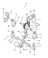
背凭れ部3の内部には、図2に示す如きマッサージ機構6が設けられている。図2は、本発明の実施の形態に係る椅子型マッサージ装置1が有するマッサージ機構6の構成を示す分解斜視図である。マッサージ機構6は被施療者の身体に機械的刺激を与える4つのローラ状の施療子10を有している。また、この施療子10を変位駆動するDCサーボモータのモータ11、12が設けられている。施療子10は2つのV字状のアーム13の先端それぞれに取り付けられている。夫々のアーム13は、略V字状をなす2つのコンロッド14に所定の範囲内で回転可能であるように夫々取り付けられている。各コンロッド14には、嵌合孔15が設けられており、この嵌合孔15に回転軸16の両端に設けられた傾斜部17が遊嵌されている。この傾斜部17は、回転軸16に対して所定角度傾斜した状態で設けられたものである。回転軸16の中間部分には、ヘリカルギヤ18aが同軸的に設けられており、このヘリカルギヤ18aがウォーム18bと噛合している。このように、ヘリカルギヤ18aとウォーム18bとでウォームギヤ機構18が構成されている。   A massage mechanism 6 as shown in FIG. 2 is provided inside the backrest 3. FIG. 2 is an exploded perspective view showing the configuration of the massage mechanism 6 included in the chair type massage apparatus 1 according to the embodiment of the present invention. The massage mechanism 6 has four roller-shaped treatment elements 10 that apply mechanical stimulation to the body of the user. Further, motors 11 and 12 of a DC servo motor that drives the treatment element 10 to be displaced are provided. The treatment element 10 is attached to each of the tips of two V-shaped arms 13. Each arm 13 is attached to two connecting rods 14 each having a substantially V shape so as to be rotatable within a predetermined range. Each connecting rod 14 is provided with a fitting hole 15, and inclined portions 17 provided at both ends of the rotating shaft 16 are loosely fitted into the fitting hole 15. The inclined portion 17 is provided in a state inclined at a predetermined angle with respect to the rotating shaft 16. A helical gear 18a is coaxially provided at an intermediate portion of the rotating shaft 16, and the helical gear 18a meshes with the worm 18b. As described above, the helical gear 18a and the worm 18b constitute the worm gear mechanism 18.

ウォーム18bの一端には、プーリ19aが同軸的に設けられており、ベルト19bによってこのプーリ19aとモータ11の出力軸に設けられたプーリ19cとが連結されている。従って、モータ11の回転運動はベルト19bを介してウォーム18bへ伝達され、ウォーム18bの回転によって回転軸16が回転する。そして、回転軸16の回転に伴い、傾斜部17が円錐形の軌跡を描くように変位し、これによってコンロッド14が規則的に動作して、左右の施療子10が近接・離反するように左右及び上下方向へ略楕円を描くように移動する。これが施療子10の揉み動作となる。なお、施療子10の揉み動作には、左右の施療子10が近接するときに前方(施療者側)へ移動し、左右の施療子10が離反するときに後方へ移動する動作も含まれる。このように、揉み動作では、施療子10が3次元的に移動することとなる。   A pulley 19a is coaxially provided at one end of the worm 18b, and the pulley 19a and a pulley 19c provided on the output shaft of the motor 11 are connected by a belt 19b. Therefore, the rotational motion of the motor 11 is transmitted to the worm 18b via the belt 19b, and the rotating shaft 16 rotates by the rotation of the worm 18b. Then, as the rotary shaft 16 rotates, the inclined portion 17 is displaced so as to draw a conical locus, whereby the connecting rod 14 operates regularly, so that the left and right treatment elements 10 approach and separate from each other. And move so as to draw a substantially ellipse in the vertical direction. This is the massage operation of the treatment element 10. It should be noted that the massage operation of the treatment element 10 includes an operation of moving to the front (the user side) when the left and right treatment elements 10 approach each other and moving backward when the left and right treatment elements 10 are separated. As described above, in the massage operation, the treatment element 10 moves three-dimensionally.

また、図2に示すように、コンロッド14の下部には嵌合穴20が設けられており、この嵌合穴20に連結部材21に設けられた突出部22が挿入されている。連結部材21には、横方向の孔23が設けられており、この孔23に、回転軸24の両端部に設けられた偏心部25が遊嵌している。また、回転軸24の中間部分にはプーリ26aが同軸的に設けられており、ベルト26bによってこのプーリ26aとモータ12の出力軸に設けられたプーリ26cとが連結されている。従って、モータ12の回転運動はベルト26bを介して回転軸24に伝達され、回転軸24の両端の偏心部25の公転によって連結部材21が略上下に移動する。この結果、コンロッド14が嵌合孔15を中心に往復回動するので施療子10が円弧を描くように略上下に往復移動する。モータ12を一定速度で回転させたときには、一定の周期で施療子10が往復移動することとなり、こが施療子10のたたき動作となる。また、モータ12をその回転速度を変化させながら回転させたときには、変則的な周期で施療子10が往復移動することとなり、これが施療子10の指圧動作となる。   As shown in FIG. 2, a fitting hole 20 is provided in the lower portion of the connecting rod 14, and a protruding portion 22 provided in the connecting member 21 is inserted into the fitting hole 20. The connecting member 21 is provided with a lateral hole 23, and eccentric portions 25 provided at both ends of the rotating shaft 24 are loosely fitted into the hole 23. A pulley 26a is coaxially provided at an intermediate portion of the rotary shaft 24, and the pulley 26a and a pulley 26c provided on the output shaft of the motor 12 are connected by a belt 26b. Therefore, the rotational movement of the motor 12 is transmitted to the rotating shaft 24 via the belt 26b, and the connecting member 21 moves substantially up and down by the revolution of the eccentric portions 25 at both ends of the rotating shaft 24. As a result, the connecting rod 14 reciprocates around the fitting hole 15 so that the treatment element 10 reciprocates substantially up and down so as to draw an arc. When the motor 12 is rotated at a constant speed, the treatment element 10 reciprocates at a constant cycle, and this is a hitting operation of the treatment element 10. Further, when the motor 12 is rotated while changing its rotation speed, the treatment element 10 reciprocates at an irregular cycle, and this is the acupressure operation of the treatment element 10.

このように、モータ11の駆動によって施療子10の揉み動作が、モータ12の駆動によって施療子10のたたき動作及び指圧動作が行われ、モータ11,12を同時に駆動することにより、揉み動作及びたたき動作又は揉み動作及び指圧動作が合成されて行われることとなる。もちろん、各動作を独立に行うことも可能である。   As described above, the squeezing operation of the treatment element 10 is performed by driving the motor 11, and the tapping operation and the acupressure operation of the treatment element 10 are performed by driving the motor 12. The motion or the squeezing motion and the acupressure motion are synthesized and performed. Of course, each operation can be performed independently.

このようなマッサージ機構6は、図1に示すように昇降台28に取り付けられており、この昇降台28の両側端にはローラ28aが設けられている。該ローラ28aは、ガイドレール29に転動することが可能であるように支持されている。また昇降台28には図示しないナットが設けられており、このナットに前記ガイドレール29と平行に設けられたねじ棒30が螺合せしめられている。該ねじ棒30その上下端が枢支されており、またその下端が背凭れ部3の下部に設けられたモータ(図示せず)の出力軸に連結されている。従って、該モータの駆動によってねじ棒30が回転したときには、ローラ28aがガイドレール29に係合していることによって、前記ナットを有する昇降台28がねじ棒30と一体的に回転することが規制され、前記ナットと前記ねじ棒30とが相対的に回転して、昇降台28及びマッサージ機構6が昇降することとなる。このような構成により、被施療者が背凭れ部3に上半身を凭れかけた状態でマッサージ機構6を昇降させることで、被施療者の背中を上下に施療子10が転動するローリング動作を行うことができる。   Such a massage mechanism 6 is attached to an elevator 28 as shown in FIG. 1, and rollers 28a are provided on both ends of the elevator 28. The roller 28 a is supported so as to be able to roll on the guide rail 29. The elevator 28 is provided with a nut (not shown), and a screw rod 30 provided in parallel with the guide rail 29 is screwed onto the nut. The upper and lower ends of the screw rod 30 are pivotally supported, and the lower ends thereof are connected to an output shaft of a motor (not shown) provided at the lower portion of the backrest 3. Therefore, when the screw rod 30 is rotated by driving the motor, the roller 28a is engaged with the guide rail 29, so that the elevator 28 having the nut is prevented from rotating integrally with the screw rod 30. Then, the nut and the screw rod 30 are relatively rotated, and the lifting platform 28 and the massage mechanism 6 are moved up and down. With this configuration, the massage mechanism 6 is moved up and down while the user is leaning on the backrest 3 to perform a rolling operation in which the treatment element 10 rolls up and down the back of the user. be able to.

次に、フットレスト4の構成について更に詳しく説明する。なお、以下の記載においては、説明を簡単にするために、フットレスト4を座面2bの前端から略鉛直下方へ延ばした状態について説明する。図3は、本発明の実施の形態に係る椅子型マッサージ装置1が有するフットレスト4の構成を示す斜視図である。図3に示すように、本実施の形態に係るフットレスト4は、脹脛載せ部材4a、足載せ部材4b及び伸縮機構4cによって主として構成されている。脹脛載せ部材4aは、座部2の座面2bの前下方に配されており、更にその下方に足載せ部材4bが配されている(図1参照)。かかる脹脛載せ部材4a及び足載せ部材4bは、座部2の上部前側に枢軸31によって回動することが可能であるように取り付けられた伸縮機構4cの前側に夫々上下に並べられた状態で取り付けられている。   Next, the configuration of the footrest 4 will be described in more detail. In the following description, a state in which the footrest 4 is extended substantially vertically downward from the front end of the seating surface 2b will be described in order to simplify the description. FIG. 3 is a perspective view showing a configuration of the footrest 4 included in the chair type massage apparatus 1 according to the embodiment of the present invention. As shown in FIG. 3, the footrest 4 according to the present embodiment is mainly configured by a calf resting member 4a, a foot resting member 4b, and a telescopic mechanism 4c. The calf resting member 4a is disposed in front of and below the seating surface 2b of the seat 2, and the foot resting member 4b is disposed further below (see FIG. 1). The calf resting member 4a and the foot resting member 4b are attached in a state where they are vertically arranged on the front side of the telescopic mechanism 4c attached to the upper front side of the seat portion 2 so as to be rotatable by the pivot 31. It has been.

図4及び図5は、脹脛載せ部材4a及び足載せ部材4bの構成を示す正面図であり、図6はその平面図である。また、図7は、脹脛載せ部材4aの構成を示す平面図であり、図8及び図9は、足載せ部材4bの構成を示す平面図である。図4乃至図7に示す如く、脹脛載せ部材4aは、被施療者の両脚の脹脛を夫々支持する脹脛支持面34と、該脹脛支持面34の両側端から前方へ延びた2つの側壁33とによって、前方及び上下端が夫々開放された1つの凹状溝部を形成するように構成されている。   4 and 5 are front views showing the configuration of the calf resting member 4a and the foot resting member 4b, and FIG. 6 is a plan view thereof. FIG. 7 is a plan view showing the configuration of the calf resting member 4a, and FIGS. 8 and 9 are plan views showing the configuration of the foot resting member 4b. As shown in FIGS. 4 to 7, the calf resting member 4 a includes a calf support surface 34 that supports calves of both legs of the user, and two side walls 33 that extend forward from both side ends of the calf support surface 34. Thus, one concave groove is formed with the front and upper and lower ends open respectively.

また、図7に示す如く、脹脛載せ部材4aの凹状溝部底面である脹脛支持面34は、被施療者の左右の脹脛を載せやすいように丸みを帯びた窪み34aが左右に並設されている。これらの窪み34aの大きさは脹脛載せ部材4aの凹状溝部の大きさに比して非常に小さく、このため脹脛支持面34は略平坦となっている。従って、被施療者が両脚の脹脛を脹脛載せ部材4aに置いたときに、脹脛支持面34の両方の窪み34aの間に形成された前方へ僅かに突出した部分によって脹脛が拘束されるようなことはなく、被施療者は下腿を脹脛載せ部材4aの凹状溝部内で自由に移動させることができ、自由な姿勢をとることが可能である。なお、ここでいう略平坦とは、被施療者の下腿の移動性を著しく損なうような突出部分が実質的に存在しない程度のものをいう。   Further, as shown in FIG. 7, the calf support surface 34, which is the bottom surface of the concave groove portion of the calf resting member 4 a, has rounded depressions 34 a arranged side by side so as to easily place the calf left and right of the user. . The size of these recesses 34a is very small compared to the size of the concave groove portion of the calf resting member 4a, so that the calf support surface 34 is substantially flat. Therefore, when the user puts the calves of both legs on the calf resting member 4a, the calf is restrained by the slightly projecting forward portion formed between both the depressions 34a of the calf support surface 34. In other words, the user can move the lower leg freely in the concave groove portion of the calf resting member 4a, and can take a free posture. Note that the term “substantially flat” as used herein refers to a portion that does not substantially have a protruding portion that significantly impairs the mobility of the lower leg of the user.

脹脛支持面34の窪み34aの夫々には空気袋35が配されており、両方の側壁33の対向面には、夫々空気袋36が配されている。空気袋35,36は夫々一端が蛇腹状に展開することが可能であり、他端が展開しないように構成されていて、略扁平な状態から給気されたときに扇状に膨張することが可能となっている。2つの空気袋35は、互いに展開可能な一端を近接させて、即ち当該一端を互いに内側へ向けて、脹脛支持面34の窪み34aに夫々固着されている。また、空気袋36は、展開可能な一端を前方へ向けて、側壁33の内側面に固着されている。各空気袋35,36は、前述した給排気装置9に連通されており、該給排気装置9を駆動することによって空気袋35,36を膨張又は収縮させることが可能となっている(図14参照)。   An air bag 35 is disposed in each of the recesses 34 a of the calf support surface 34, and an air bag 36 is disposed on the opposing surface of both side walls 33. Each of the air bags 35 and 36 can be expanded in a bellows shape at one end and is not expanded at the other end, and can expand into a fan shape when supplied from a substantially flat state. It has become. The two air bags 35 are fixed to the recesses 34a of the calf support surface 34 with their one deployable ends close to each other, that is, with the one ends facing each other inward. The air bag 36 is fixed to the inner side surface of the side wall 33 with one expandable end facing forward. The air bags 35 and 36 are communicated with the air supply / exhaust device 9 described above, and the air bags 35 and 36 can be expanded or contracted by driving the air supply / exhaust device 9 (FIG. 14). reference).

右側の空気袋35,36は被施療者の右脚の脹脛の施療に用いられ、左側の空気袋35,36は被施療者の左脚の脹脛の施療に用いられる。空気袋35の前面及び2つの空気袋36の互いに対向する面は、夫々被施療者の脹脛の後部及び外側部を押圧する押圧面35a,36aとなっている。右側の空気袋35,36は夫々給気されたときに、押圧面35a,36aが近接するように扇状に膨張する。また、左側の空気袋35,36も夫々給気されたときに押圧面35a,36aが近接するように扇状に膨張する。これにより、被施療者の脹脛を挟んで当該脹脛に押圧刺激を与えることができるようになっている。   The right air bladders 35 and 36 are used for the treatment of the right leg calf for the user, and the left air bags 35 and 36 are used for the treatment of the calf for the left leg of the user. The front surface of the air bag 35 and the surfaces of the two air bags 36 facing each other are pressing surfaces 35a and 36a that press the rear and outer portions of the calf of the user. When the right air bladders 35 and 36 are supplied with air, the air bags 35 and 36 expand in a fan shape so that the pressing surfaces 35a and 36a are close to each other. Further, the left air bladders 35 and 36 also expand in a fan shape so that the pressing surfaces 35a and 36a come close to each other when supplied. Thereby, a pressing stimulus can be given to the calf with the calf's calf interposed therebetween.

このように、空気袋35,36によって、本発明に係る脹脛施療部が構成されている。   Thus, the calves treatment part based on this invention is comprised by the air bags 35 and 36. FIG.

一方、図4,図5,図6,図8及び図9に示す如く、足載せ部材4bは、被施療者の足底を夫々支持する足底支持面37と、該足底支持面37の後側に立設された踵支持面38と、足底支持面37の両側端から上方へ延びた2つの側壁39とによって、前方及び上方が夫々開放された1つの凹部を形成するように構成されている。なお、ここでいう足とは、足首から下の部分を意味するものとしている。   On the other hand, as shown in FIGS. 4, 5, 6, 8, and 9, the footrest member 4 b includes a sole support surface 37 that supports the sole of the user, and the sole support surface 37. The heel support surface 38 erected on the rear side and the two side walls 39 extending upward from both side ends of the sole support surface 37 are configured to form one concave portion that is open on the front and upper sides, respectively. Has been. Here, the foot means a portion below the ankle.

足底支持面37は横方向中央部分が若干上方へ突出しており、図9に示す如く、この突出部分37aによって、被施療者の右の足底を支持する右足底支持位置37bと、左の足底を支持する左足底支持位置37cとが規定されている。また、右足底支持位置37bには、前後に離隔した2箇所に空気袋40,41が取り付けられており、これらの空気袋40,41の間にバイブレータ42が取り付けられている。左足底支持位置37cにも、空気袋40、バイブレータ42及び空気袋41がこの順番で前方から後方へ並べて配されている。   As shown in FIG. 9, the sole support surface 37 has a laterally central portion protruding slightly upward. As shown in FIG. 9, a right foot support position 37b for supporting the right foot sole of the user, A left sole support position 37c for supporting the sole is defined. In addition, air bags 40 and 41 are attached to the right sole support position 37b at two locations separated in the front-rear direction, and a vibrator 42 is attached between these air bags 40 and 41. An air bag 40, a vibrator 42, and an air bag 41 are also arranged in this order from the front to the rear at the left sole support position 37c.

空気袋40,41は、夫々前述した空気袋35,36とは異なり、蛇腹部分を有しておらず、扁平な状態から給気されたときに略楕円状に膨張するように構成されている。かかる空気袋40,41もまた、給排気装置9に連通されており、給排気装置9を駆動することによって膨張又は収縮することが可能とされている。バイブレータ42は、例えばDCサーボモータの出力軸に偏心質量が取り付けられた如き構成のものであり、駆動されることによって微振動を発生することができる。かかる構成によって、空気袋40,41の膨張及び収縮を繰り返すことにより、被施療者の足底に対して押圧刺激をその強弱を変化させながら与えることができ、またバイブレータ42を動作させることにより、被施療者の足底に振動刺激を与えることができる。   Unlike the air bags 35 and 36 described above, the air bags 40 and 41 do not have a bellows portion and are configured to expand in a substantially elliptical shape when supplied from a flat state. . The air bags 40 and 41 are also communicated with the air supply / exhaust device 9 and can be expanded or contracted by driving the air supply / exhaust device 9. The vibrator 42 has a configuration in which an eccentric mass is attached to an output shaft of a DC servo motor, for example, and can generate fine vibration when driven. By repeating the expansion and contraction of the air bags 40 and 41 by such a configuration, it is possible to give a pressure stimulus to the sole of the user while changing the strength thereof, and by operating the vibrator 42, Vibration stimulus can be applied to the sole of the user.

このように、空気袋40,41及びバイブレータ42によって、本発明に係る足底施療部が構成されている。   Thus, the soles according to the present invention are configured by the air bags 40 and 41 and the vibrator 42.

踵支持面38は、被施療者の両方の踵の後部を夫々支持すべく、2つの凹状面38aが左右に並設された形状をなしており、図5に示す如く、夫々の凹状面38aによって、被施療者の右側の踵を支持する右踵支持位置38bと、左側の踵を支持する左踵支持位置38cとが規定されている。換言すれば、踵支持面38は、両方の凹状面38aの間に形成された突出面38dを有しており、この突出面38dによって、右踵支持位置38bと、左踵支持位置38cとが規定されている。これらの右踵支持位置38b及び左踵支持位置38cは、被施療者が椅子型マッサージ装置1を使用するときに、被施療者の両脚の踵置きとして用いられる。このとき、突出面38dが設けられていることにより、着座時に被施療者の踵が夫々右踵支持位置38b及び左踵支持位置38cに案内されることとなる。   The heel support surface 38 has a shape in which two concave surfaces 38a are arranged side by side so as to support the rear portions of both heels of the user. As shown in FIG. 5, the respective concave surfaces 38a are provided. Defines a starboard support position 38b for supporting the right eyelid of the user and a port support position 38c for supporting the left eyelid. In other words, the heel support surface 38 has a projecting surface 38d formed between both concave surfaces 38a, and the starboard support position 38b and the port side support position 38c are separated by the projecting surface 38d. It is prescribed. These starboard support positions 38b and port support positions 38c are used as a laying position for both legs of the user when the user uses the chair-type massage apparatus 1. At this time, the protrusion surface 38d is provided, so that the user's heel is guided to the starboard support position 38b and the portside support position 38c, respectively, when sitting.

前記突出面38dは、足載せ部材4bの後端から前後方向中央より若干後方の箇所まで突出しており、それより前方は突出部分37aに連なっている。また、突出部分37aは、突出面38dに比べて高さが十分に低いため、突出面38dより前方は開放されており、中間壁のような被施療者の足先を拘束する部分が存在しない。よって、被施療者は、足先を自由に置くことができ、椅子型マッサージ装置1に着座しているときに様々な姿勢をとることが可能である。   The protruding surface 38d protrudes from the rear end of the footrest member 4b to a position slightly rearward from the center in the front-rear direction, and the front is continuous with the protruding portion 37a. Further, since the protruding portion 37a is sufficiently lower than the protruding surface 38d, the protruding portion 37a is opened in front of the protruding surface 38d, and there is no portion that restrains the foot of the user such as an intermediate wall. . Therefore, the user can place his / her toes freely and can take various postures while sitting on the chair type massage apparatus 1.

また、凹状面38aの対向部分には、給排気装置9に連通された空気袋43が夫々取り付けられている。即ち、1つの凹状面38aにつき2つの空気袋43が設けられており、踵支持面38には合計4つの空気袋43が設けられていることとなる。夫々の空気袋43は、前述した空気袋35,36と同様の構成とされており、蛇腹状の展開可能な一端を前方へ向けて踵支持面38に固着されている。凹状面38aは、前方へ向けて幅が広くなるように、その対向部分がテーパ面とされており、これによって1つの凹状面38aに取り付けられた2つの空気袋43は、展開可能な前端同士の離隔距離が、展開不能な後端同士の離隔距離に比して大きくなるように、互いに傾斜して配置されている。かかる一対の空気袋43の夫々の対向面は、被施療者の踵の後部を押圧する押圧面43aとなっており、夫々の空気袋43は給気されたときに押圧面43aが互いに近接するように扇状に膨張する。これにより、被施療者の踵の後部を挟んで当該踵の後部に押圧刺激を与えることができるようになっている。   Air bags 43 communicated with the air supply / exhaust device 9 are respectively attached to the opposing portions of the concave surface 38a. That is, two air bags 43 are provided for each concave surface 38a, and a total of four air bags 43 are provided on the heel support surface 38. Each of the air bags 43 has the same structure as the air bags 35 and 36 described above, and is fixed to the heel support surface 38 with the one end of the bellows-like deployable facing forward. The concave surface 38a is tapered so that the width thereof becomes wider toward the front, whereby the two air bags 43 attached to one concave surface 38a have two front ends that can be deployed. Are arranged so as to be inclined with respect to each other so that the distance between them becomes larger than the distance between the rear ends that cannot be deployed. The opposing surfaces of the pair of air bags 43 serve as pressing surfaces 43a that press the rear part of the patient's heel, and the pressing surfaces 43a approach each other when the air bags 43 are supplied with air. It expands like a fan. Thereby, a pressure stimulus can be given to the back part of the said eyelid across the back part of a user's eyelid.

このように、空気袋43によって、本発明に係る踵施療部が構成されており、空気袋40,41,43及びバイブレータ42によって、本発明に係る足施療部が構成されている。   In this manner, the air bag 43 constitutes the heel treatment part according to the present invention, and the air bags 40, 41, 43 and the vibrator 42 constitute the foot treatment part according to the present invention.

側壁39は、踵支持面38の両側端部分、即ち、4つの空気袋43のうちの両外側に配された2つが取り付けられた部分から前方へ連なって設けられており、かかる側壁39に被施療者の足の外側部分が対向するようになっている。夫々の側壁39の対向面には、給排気装置9に連通された空気袋44が夫々取り付けられている。夫々の空気袋44は、空気袋35,36,43と同様の構成とされており、蛇腹状の展開可能な一端を上方へ向けて側壁39の内側面に固着されている。両方の空気袋44の対向面は、夫々被施療者の足の甲を押圧する押圧面44aとなっている。これによって、空気袋43が扁平な状態から給気された場合には、押圧面44aが傾斜角度を変化させながら下方へ向けて移動することとなり、該押圧面44aによって被施療者の足の甲が押圧される。   The side walls 39 are provided to the front side from both side end portions of the heel support surface 38, that is, the portions to which two of the four air bags 43 are attached. The outer portions of the user's legs are opposed to each other. Air bags 44 communicated with the air supply / exhaust device 9 are attached to the opposing surfaces of the respective side walls 39. Each air bag 44 has the same configuration as the air bags 35, 36, and 43, and is fixed to the inner side surface of the side wall 39 with one end of the bellows-like expandable side facing upward. The opposing surfaces of both air bags 44 are pressing surfaces 44a that press the back of the user's foot. Thus, when the air bladder 43 is supplied from a flat state, the pressing surface 44a moves downward while changing the inclination angle, and the back surface of the user's foot is moved by the pressing surface 44a. Is pressed.

このように、空気袋44によって、本発明に係る足背押圧部が構成されている。   As described above, the air bag 44 constitutes the foot back pressing portion according to the present invention.

以上説明した如き構成の脹脛載せ部材4a及び足載せ部材4bは、図3に示す如く伸縮機構4cに取り付けられており、互いに近接又は離反するように相対移動することが可能となっている。図10〜図13は、伸縮機構4cの構成を示す斜視図であり、図10及び図11は、最も縮短された状態の伸縮機構4cを斜め前方及び斜め後方からみたときの図であり、図12及び図13は、最も伸長された状態の伸縮機構4cを斜め前方及び斜め後方からみたときの図である。図10及び図12に示す如く、伸縮機構4cは、上部部材45と、中間部材46と、下部部材47とによって主として構成されている。上部部材45は、2つの平行な縦長の角管48を有しており、該角管48の上端部分が互いに連結部材49によって連結された構成となっている。また、強度確保のために、棒状の強度部材50が、2つの角管48の中間部分の間を渡すように設けられている。   The calf resting member 4a and the foot resting member 4b configured as described above are attached to the telescopic mechanism 4c as shown in FIG. 3, and can move relative to each other so as to be close to or away from each other. 10 to 13 are perspective views showing the configuration of the expansion / contraction mechanism 4c, and FIGS. 10 and 11 are views when the expansion / contraction mechanism 4c in the most contracted state is viewed obliquely forward and obliquely rearward. 12 and 13 are views of the telescopic mechanism 4c in the most extended state when viewed obliquely from the front and from the rear. As shown in FIGS. 10 and 12, the telescopic mechanism 4 c is mainly configured by an upper member 45, an intermediate member 46, and a lower member 47. The upper member 45 has two parallel vertically long rectangular tubes 48, and the upper end portions of the rectangular tubes 48 are connected to each other by a connecting member 49. Further, in order to ensure the strength, a rod-shaped strength member 50 is provided so as to pass between the intermediate portions of the two rectangular tubes 48.

連結部材49はその中間部分において前方へ突出するように屈曲せしめられており、この突出部分49aに伸縮腕51の一端の関節が、前後方向へ延びる枢軸によって枢着されている。伸縮腕51は、3つの菱形が連続したパンタグラフ機構である。   The connecting member 49 is bent so as to protrude forward at an intermediate portion thereof, and a joint at one end of the telescopic arm 51 is pivotally attached to the protruding portion 49a by a pivot extending in the front-rear direction. The telescopic arm 51 is a pantograph mechanism in which three rhombuses are continuous.

また、夫々の角管48の中間部分の前側には、取付部材48aが夫々固着されている。夫々の取付部材48aは前方へ向かった平面部分を有しており、この平面部分に前述した脹脛載せ部材4aを取り付けるようになっている(図4参照)。   In addition, attachment members 48 a are fixed to the front side of the intermediate portion of each square tube 48. Each mounting member 48a has a flat portion facing forward, and the calf resting member 4a is mounted on this flat portion (see FIG. 4).

更に、夫々の角管48の上端部外側には、前述した枢軸31が横方向へ延びている。これによって、上部部材45は座部2に対して前後方向へ回動することが可能となっている。また、この枢軸31は、座部2に内蔵された図示しない回動装置に連結されており、椅子型マッサージ装置1に設けられた操作部66(図14参照)に対して被施療者が所定の操作入力を行うことにより、自動的にフットレスト4を前後へ回動させることが可能となっている。   Further, the above-described pivot shaft 31 extends laterally outside the upper end portion of each square tube 48. Accordingly, the upper member 45 can be rotated in the front-rear direction with respect to the seat portion 2. Further, the pivot 31 is connected to a rotation device (not shown) built in the seat 2, and the user receives a predetermined response to the operation unit 66 (see FIG. 14) provided in the chair type massage device 1. By performing the operation input, it is possible to automatically rotate the footrest 4 back and forth.

一方、中間部材46は、平行な縦長の角棒状をなす2つのスライド棒52と、両スライド棒52の下端を連結する横長の連結棒53とを有している。スライド棒52は、夫々角管48に挿入されており、これによって2つのスライド棒52が一体的に夫々の角管48に進入及び退出することが可能となっている。また、連結棒53の横方向中央には、縦長のナット54の下端が取り付けられている。該ナット54にはねじ棒55が螺合しており、ナット54の上端からこのねじ棒55の上部が突出している。   On the other hand, the intermediate member 46 has two slide rods 52 each having a parallel vertically long rectangular bar shape, and a horizontally long connection rod 53 that connects lower ends of both slide rods 52. The slide rods 52 are respectively inserted into the square tubes 48, whereby the two slide rods 52 can enter and exit the respective square tubes 48 integrally. Further, a lower end of a vertically long nut 54 is attached to the center of the connecting rod 53 in the horizontal direction. A screw rod 55 is screwed onto the nut 54, and the upper portion of the screw rod 55 protrudes from the upper end of the nut 54.

ねじ棒55は、連結部材49の突出部分49aの裏側、即ち凹状に窪んだ部分に、軸心を中心として回転することが可能であるように枢着されている。また、連結部材49のねじ棒55の取付箇所の側方には、モータ56が取り付けられており、該モータ56とねじ棒55とが、ベルト及びプーリによって構成された回転伝達機構56aにて連結されている。これにより、モータ56の出力軸の回転運動がねじ棒55に伝達され、ねじ棒55をナット54に進入及び退出させることが可能である。   The screw rod 55 is pivotally attached to the back side of the protruding portion 49a of the connecting member 49, that is, a concavely recessed portion so as to be able to rotate about the axis. A motor 56 is attached to a side of the connecting member 49 where the screw rod 55 is attached, and the motor 56 and the screw rod 55 are connected by a rotation transmission mechanism 56a formed of a belt and a pulley. Has been. Thereby, the rotational motion of the output shaft of the motor 56 is transmitted to the screw rod 55, and the screw rod 55 can enter and leave the nut 54.

また、ナット54はその外観が角棒状となっており、その長手方向中央部分において伸縮腕51の中間の2つのリンクが交差した関節が、前後方向へ延びる枢軸によって枢着されている。これにより、モータ56を駆動させることによって中間部材46が下降又は上昇し、これに伴って伸縮腕51が伸長又は縮短することとなる。   Further, the nut 54 has a square bar-like appearance, and a joint where two links in the middle of the telescopic arm 51 intersect at the central portion in the longitudinal direction is pivotally attached by a pivot extending in the front-rear direction. Thereby, by driving the motor 56, the intermediate member 46 descends or rises, and the telescopic arm 51 extends or contracts accordingly.

夫々の角管48の対向面、即ち内側面の下端から中央部分にかけて、上下に長い切り欠き48bが設けられている。また、スライド棒52の夫々の長手方向中央部分からは、連結板52aが内側へ、即ち他方のスライド棒52側へ延設されており、この連結板52aにスライド棒52と平行な丸孔を有するガイド57が設けられている。連結板52aは切り欠き48bを貫通して角管48の内外へ渡されており、これによって、連結板52aと角管48とが干渉することなく、スライド棒52を角管48に進入させ留ことが可能であり、またスライド棒52を角管48から退出させることが可能となっている。このようにして、スライド棒52,連結板52a及びガイド57は昇降することが可能とされている。   A long notch 48b is provided in the vertical direction from the opposite surface of each square tube 48, that is, from the lower end of the inner side surface to the central portion. Further, a connecting plate 52a is extended inward from the center portion in the longitudinal direction of each slide bar 52, that is, toward the other slide rod 52, and a round hole parallel to the slide bar 52 is formed in the connecting plate 52a. A guide 57 is provided. The connecting plate 52a passes through the notch 48b and is passed into and out of the square tube 48, whereby the slide bar 52 enters the square tube 48 without interference between the connecting plate 52a and the square tube 48. In addition, the slide bar 52 can be retracted from the square tube 48. In this way, the slide bar 52, the connecting plate 52a, and the guide 57 can be moved up and down.

下部部材47は、2つのスライド棒58と、2つの取付部材59と、支持枠60とによって主として構成されている。スライド棒58は、ガイド57に設けられた丸孔よりも若干直径が小さい丸棒状をなしており、ガイド57の丸孔に挿通されている。夫々のスライド棒58の下端は、横長の連結部材58aによって連結されている。また、各スライド棒58の下端部分には、夫々取付部材59が取り付けられている。これらの取付部材59は、前方へ向かった平面部分を有しており、この平面部分に前述した足載せ部材4bを取り付けるようになっている(図4参照)。   The lower member 47 is mainly composed of two slide bars 58, two attachment members 59, and a support frame 60. The slide bar 58 has a round bar shape slightly smaller in diameter than the round hole provided in the guide 57, and is inserted through the round hole of the guide 57. The lower end of each slide bar 58 is connected by a horizontally long connecting member 58a. Further, an attachment member 59 is attached to the lower end portion of each slide bar 58. These attachment members 59 have a flat portion facing forward, and the above-described footrest member 4b is attached to this flat portion (see FIG. 4).

また、取付部材59の下端からは、略水平面を構成する支持枠60が前方へ延設されている。この支持枠60には、足載せ部材4bの下底面が載せられるようになっている(図4参照)。図4に示す如く、脹脛載せ部材4a及び足載せ部材4bの横幅は略同寸であり、また図には示していないが、脹脛載せ部材4a及び足載せ部材4bが伸縮機構4cに取り付けられたときには、脹脛支持面34よりも踵支持面38の奥部の方が若干後方に位置している。これにより、被施療者の踵を足載せ部材4bに置きやすい構造となり、被施療者がフットレスト4に容易に両脚を載せることができる。   Further, a support frame 60 that constitutes a substantially horizontal plane extends forward from the lower end of the attachment member 59. A lower bottom surface of the footrest member 4b is placed on the support frame 60 (see FIG. 4). As shown in FIG. 4, the lateral widths of the calf resting member 4a and the foot resting member 4b are substantially the same, and although not shown in the figure, the calf placing member 4a and the foot resting member 4b are attached to the telescopic mechanism 4c. In some cases, the back of the heel support surface 38 is located slightly rearward of the calf support surface 34. Thereby, it becomes a structure where the user's heel is easily placed on the footrest member 4 b, and the user can easily put both legs on the footrest 4.

また、両方の取付部材59の下端外側には、夫々車輪61を横方向の枢軸回りに回動することが可能であるように枢着してある。これらの車輪61は、伸縮機構4cを最も縮短した状態のときには接地していない。   Further, the wheels 61 are pivotally attached to the outer sides of the lower ends of both the attachment members 59 so that the wheels 61 can be rotated around the pivot in the horizontal direction. These wheels 61 are not grounded when the telescopic mechanism 4c is in the most contracted state.

夫々の取付部材59の上端は、横長の連結板59aによって連結されており、この連結板59aには、伸縮腕51の下端の関節が、前後方向へ伸びる枢軸によって枢着されている。従って、モータ56の駆動によって中間部材46が上部部材45に対して離反又は近接する方向へ移動し、伸縮腕51が伸長又は縮短したときに、下部部材47も中間部材46に対して離反又は近接する方向へスライドし、伸縮機構4cが全体として伸長又は縮短することとなる。   The upper end of each attachment member 59 is connected by a horizontally long connecting plate 59a, and the joint at the lower end of the telescopic arm 51 is pivotally attached to the connecting plate 59a by a pivot extending in the front-rear direction. Therefore, when the intermediate member 46 is moved away from or close to the upper member 45 by driving the motor 56 and the telescopic arm 51 is extended or contracted, the lower member 47 is also separated from or close to the intermediate member 46. And the expansion / contraction mechanism 4c expands or contracts as a whole.

図14は、本発明の実施の形態に係る椅子型マッサージ装置の構成の一部を示すブロック図である。図14に示す如く、椅子型マッサージ装置1には、制御回路62が設けられている。該制御回路62は、CPU、ROM、RAM、及び入出力インタフェース等から構成されており、座部2又は背凭れ部3の内部に配されている。該制御回路62は、駆動回路63に接続されており、該駆動回路63が給排気装置9に接続されている。給排気装置9は、電磁弁等の切替バルブ及びエアポンプ等によって構成されており、エアホースによって各空気袋35,36,40,41,43,44に連通せしめられている。また、給排気装置9は、空気袋35,36,40,41,43,44に対して各々独立的に吸気及び排気を行うことが可能となっている。また、駆動回路63は、制御回路62から受信した制御信号に応じて給排気装置9を駆動すべく構成されている。   FIG. 14 is a block diagram showing a part of the configuration of the chair-type massage apparatus according to the embodiment of the present invention. As shown in FIG. 14, the chair type massage apparatus 1 is provided with a control circuit 62. The control circuit 62 includes a CPU, a ROM, a RAM, an input / output interface, and the like, and is disposed inside the seat 2 or the backrest 3. The control circuit 62 is connected to a drive circuit 63, and the drive circuit 63 is connected to the air supply / exhaust device 9. The air supply / exhaust device 9 includes a switching valve such as a solenoid valve, an air pump, and the like, and is communicated with each air bag 35, 36, 40, 41, 43, 44 by an air hose. The air supply / exhaust device 9 can perform intake and exhaust independently of the air bags 35, 36, 40, 41, 43 and 44. The drive circuit 63 is configured to drive the air supply / exhaust device 9 in accordance with a control signal received from the control circuit 62.

また、制御回路62は、駆動回路64に接続されており、該駆動回路64がバイブレータ42に接続されている。駆動回路64は、制御回路62から受信した制御信号に応じてバイブレータ42を各々独立に駆動すべく構成されている。   The control circuit 62 is connected to the drive circuit 64, and the drive circuit 64 is connected to the vibrator 42. The drive circuit 64 is configured to drive each of the vibrators 42 in accordance with the control signal received from the control circuit 62.

また、制御回路62は、駆動回路65に接続されており、該駆動回路65がモータ56に接続されている。駆動回路65は、制御回路62から受信した制御信号に応じてモータ56を駆動すべく構成されている。   The control circuit 62 is connected to the drive circuit 65, and the drive circuit 65 is connected to the motor 56. The drive circuit 65 is configured to drive the motor 56 in accordance with the control signal received from the control circuit 62.

更に、制御回路62には、複数の操作キーが設けられた操作部66が接続されている。操作キー及びその組み合わせに対応して椅子型マッサージ装置1の動作が予め設定されており、被施療者が所望の動作に対応する操作キーを押下したときに、この操作信号が制御回路62に送信され、制御回路62は当該操作入力に対応する制御信号を出力するようになっている。   Further, an operation unit 66 provided with a plurality of operation keys is connected to the control circuit 62. The operation of the chair type massage device 1 is set in advance corresponding to the operation key and the combination thereof, and this operation signal is transmitted to the control circuit 62 when the user presses the operation key corresponding to the desired operation. The control circuit 62 outputs a control signal corresponding to the operation input.

次に、本発明の実施の形態に係る椅子型マッサージ装置1の動作について説明する。被施療者が椅子型マッサージ装置1を使用する場合には、被施療者は座面2bに着座し、両脚をフットレスト4に載せる。このとき、被施療者は両脚を目視して右踵支持位置38b及び左踵支持位置38cに夫々の踵を載せなくても、両方の踵を足載せ部材4bの突出面38dに当てて奥側(後方)へ移動させるだけで、容易に両足底を右足底支持位置37b及び左足底支持位置37cに夫々載せることができる。   Next, operation | movement of the chair type massage apparatus 1 which concerns on embodiment of this invention is demonstrated. When the user uses the chair-type massage device 1, the user sits on the seat surface 2 b and places both legs on the footrest 4. At this time, even if the user visually observes both legs and does not place the respective heels on the starboard support position 38b and the left heel support position 38c, the user places both heels on the projecting surface 38d of the footrest member 4b. It is possible to easily put both soles on the right sole support position 37b and the left sole support position 37c, respectively, simply by moving to (rear).

また、脹脛支持面34が略平坦に構成されており、左右の脹脛を拘束する中間壁等が存在しないため、被施療者は脹脛載せ部材4aの凹状溝部内で脹脛を自由に動かすことができ、膝を合わせる等の楽な姿勢をとることが可能であり、また従来の椅子型マッサージ装置のように、2つの凹状部分に左右の脹脛を夫々挿入するという煩雑な手間がなく、容易に脹脛をフットレスト4に置くことができる。   Further, since the calf support surface 34 is configured to be substantially flat and there is no intermediate wall or the like for restraining the left and right calves, the user can freely move the calf within the concave groove of the calf placing member 4a. It is possible to take an easy posture such as knee-joining, and there is no troublesome work of inserting the right and left calves into the two concave portions unlike the conventional chair type massage device, and the calves can be easily Can be placed on the footrest 4.

更に、突出面38dより前方にある足底支持面37は、突出部分37aがあるものの該突出部分37aは踵支持面38及び側壁39の高さに比べて非常に低いため略平坦であり、これによって突出面38dより前方の空間は開放されているため、被施療者は足先を自由に動かすことができ、より一層楽な姿勢をとることが可能である。   Further, the sole support surface 37 in front of the projecting surface 38d has a projecting portion 37a, but the projecting portion 37a is substantially flat compared to the height of the heel support surface 38 and the side wall 39, and this is substantially flat. Therefore, the space in front of the projecting surface 38d is opened, so that the user can freely move his / her toes and can take a more comfortable posture.

また、被施療者が操作部66(図14参照)に対して所定の操作入力を行った場合には、操作部66から操作信号が制御回路62へ送信され、この操作信号に対応する制御信号が駆動回路65へ送信される。駆動回路65がかかる制御信号に応じてモータ56を駆動し、これによってフットレスト4が伸縮される。これにより、足底支持面37及び踵支持面38の座面2bとの離隔距離が変化されることとなり、被施療者は、足底支持面37を自身の脚の長さに合わせてこの離隔距離を調節する。このとき、前記操作部66に対して前記所定の操作入力とは異なる操作入力を行って、フットレスト4を前後に回動させ、足底支持面37及び踵支持面38と座面2bとの角度を変化させることもできる。   When the user performs a predetermined operation input to the operation unit 66 (see FIG. 14), an operation signal is transmitted from the operation unit 66 to the control circuit 62, and a control signal corresponding to the operation signal is transmitted. Is transmitted to the drive circuit 65. The drive circuit 65 drives the motor 56 in response to the control signal, and thereby the footrest 4 is expanded and contracted. As a result, the separation distance between the sole support surface 37 and the heel support surface 38 from the seating surface 2b is changed, and the user adjusts the sole support surface 37 according to the length of his / her own leg. Adjust the distance. At this time, an operation input different from the predetermined operation input is performed on the operation unit 66 to rotate the footrest 4 back and forth, and the angle between the sole support surface 37 and the heel support surface 38 and the seat surface 2b. Can also be changed.

また、フットレスト4を伸長させた場合には、車輪61が床に接触することもある。フットレスト4は、鉛直下方へ延びた状態(即ち、図1に示す如き状態)よりも前方へ回動されたときには、自重によって鉛直下方へ延びた状態へ復帰することがないように、その角度を維持すべく構成されている。この構成について更に詳しく説明すると、前述した回動装置を動作させることにより、フットレスト4の傾斜角度を変化させた場合には、変化させた後の傾斜角度よりも後方へのフットレストの回動は制限されるが、その傾斜角度よりも前方への回動は自由となっている。従って、前記傾斜角度よりも前方へは手動でフットレストを回動させることは可能である。このような構成により、フットレスト4を伸長させた途中で車輪61が床に接触した場合には、フットレスト4の伸長に従って車輪61が床上を転動し、これに伴ってフットレストが前方へ回動することとなる。これにより、床面を傷つけることなくフットレストの伸長を円滑に行うことができる。   Further, when the footrest 4 is extended, the wheel 61 may come into contact with the floor. When the footrest 4 is rotated forward from the vertically extended state (that is, the state shown in FIG. 1), the angle is adjusted so that the footrest 4 does not return to the vertically extended state by its own weight. Configured to maintain. This configuration will be described in more detail. When the inclination angle of the footrest 4 is changed by operating the above-described rotation device, the rotation of the footrest to the rear of the changed inclination angle is restricted. However, the forward rotation is free from the inclination angle. Therefore, it is possible to manually rotate the footrest ahead of the inclination angle. With such a configuration, when the wheel 61 comes into contact with the floor while the footrest 4 is being extended, the wheel 61 rolls on the floor according to the extension of the footrest 4, and the footrest is rotated forward accordingly. It will be. Thereby, an extension of a footrest can be performed smoothly, without damaging a floor surface.

被施療者は、以上のようにフットレスト4の伸縮調整及び角度調整を行い、被施療者が所望の姿勢で、右足底支持位置37b及び左足底支持位置37cに夫々右足底及び左足底を載せた状態とする。この後に、被施療者が操作部66に対して脚部のマッサージ開始を指示する操作入力を行うことにより、脚部のマッサージが開始される。   The user performs the expansion and contraction adjustment and the angle adjustment of the footrest 4 as described above, and the user places the right and left soles on the right sole support position 37b and the left sole support position 37c, respectively, in a desired posture. State. Thereafter, the user performs an operation input for instructing the operation unit 66 to start the massage of the leg, whereby the massage of the leg is started.

制御回路62は、脚部のマッサージの開始の指示に対応する操作信号を受信したときには、これに対応付けられた制御信号を駆動回路63及び/又は駆動回路64に送信する。これにより、空気袋35,36,40,41,43,44及びバイブレータ42がの一部若しくは全部が所定の順番で駆動され、又は同時に駆動される。   When the control circuit 62 receives an operation signal corresponding to an instruction to start massage of the leg, the control circuit 62 transmits a control signal associated therewith to the drive circuit 63 and / or the drive circuit 64. Thereby, a part or all of the air bags 35, 36, 40, 41, 43, 44 and the vibrator 42 are driven in a predetermined order, or simultaneously driven.

被施療者の脹脛に対して施療が行われる場合には、給排気装置9が空気袋35,36に対して給気及び排気を繰り返す。これにより、空気袋35,36が、押圧面35a,36aを互いに近接及び離反させるように膨張及び収縮を繰り返し、これにより、被施療者の脹脛を挟んで当該脹脛に強弱を繰り返す押圧刺激を与えることができる。   When the treatment is performed on the calf of the user, the air supply / exhaust device 9 repeats air supply and exhaust to the air bags 35 and 36. Thereby, the air bags 35 and 36 are repeatedly expanded and contracted so that the pressing surfaces 35a and 36a are brought close to and away from each other, thereby giving a pressing stimulus that repeatedly repeats the strength of the calf with the calf of the user. be able to.

ここで、本実施の形態においては、空気袋35,36によって被施療者の脹脛を施療する構成としたので、痛みに対して比較的敏感な脹脛を空気袋35,36によって圧迫することにより、被施療者に殆ど痛みを感じさせずに脹脛の効果的なマッサージが可能となる。   Here, in the present embodiment, since the calf of the user is treated with the air bags 35, 36, the calf relatively sensitive to pain is compressed with the air bags 35, 36. An effective massage of the calf can be performed with almost no pain in the user.

また、被施療者の足底に対して施療が行われる場合には、給排気装置9が空気袋40,41に対して給気及び排気を繰り返す。これにより、空気袋40,41が膨張及び収縮を繰り返し、これにより、被施療者の足底に対して強弱を繰り返す押圧刺激を与えることができる。更にこれと同時に、又は別個に、バイブレータ42を振動させることもできる。これにより、被施療者の足底に対して振動刺激を与えることができる。   Further, when the treatment is performed on the sole of the user, the air supply / exhaust device 9 repeats air supply and exhaust to the air bags 40 and 41. Thereby, the air bags 40 and 41 repeat expansion | swelling and shrinkage | contraction, and can thereby give the pressure stimulus which repeats strength to a user's sole. Furthermore, the vibrator 42 can be vibrated simultaneously or separately. Thereby, a vibration stimulus can be given to the sole of the user.

ここで、本実施の形態においては、空気袋40,41によって被施療者の足底を施療する構成としたので、痛みに対して比較的敏感な足底を空気袋40,41によって圧迫することにより、被施療者に殆ど痛みを感じさせずに足底の効果的なマッサージが可能となる。また、空気袋40,41に加えてバイブレータ42によっても被施療者の足底を施療する構成であるので、圧迫刺激に加えて振動刺激を被施療者の足底に与えることができ、より一層多様な刺激を足底に与えることができる。   Here, in the present embodiment, since the soles of the user are treated by the air bags 40 and 41, the soles that are relatively sensitive to pain are compressed by the air bags 40 and 41. Thus, an effective massage of the sole can be performed with almost no pain in the user. Moreover, since it is the structure which treats a patient's sole with the vibrator 42 in addition to the air bags 40 and 41, in addition to a compression stimulus, a vibration stimulus can be given to a patient's sole, and much more. Various stimuli can be given to the sole.

また、給排気装置9が空気袋40,41への給排気と同時に空気袋44に対して給気を行って空気袋44を膨張させ、被施療者の足の甲を空気袋44の押圧面44aによって下方へ押圧することもできる。これにより、空気袋40,41の押圧によって被施療者の足底が上方へ逃げることを抑制でき、空気袋40,41による押圧刺激を被施療者の足底により一層効率的に与えることができる。更に、バイブレータ42の駆動と同時に、空気袋44を膨張させることにより、被施療者の足底をバイブレータ42に押し付けることができ、バイブレータ42による振動刺激を被施療者の足底により一層効率的に与えることができる。また、このように被施療者の足の甲を下方へ押圧することにより、足の位置のずれを防止することもできる。   Further, the air supply / exhaust device 9 supplies air to the air bag 44 simultaneously with air supply / exhaust to the air bags 40 and 41 to inflate the air bag 44, and the back of the user's foot is pressed against the pressure surface of the air bag 44. It can also be pressed downward by 44a. Thereby, it can suppress that a user's foot sole escapes upward by press of air bags 40 and 41, and can give pressure stimulus by air bags 40 and 41 to a user's sole more efficiently. . Further, by inflating the air bag 44 simultaneously with the driving of the vibrator 42, the sole of the user can be pressed against the vibrator 42, and vibration stimulation by the vibrator 42 can be more efficiently applied to the sole of the user. Can be given. In addition, it is possible to prevent the shift of the position of the foot by pressing the back of the user's foot in this way.

また、被施療者の踵の後部に対して施療が行われる場合には、給排気装置9が空気袋43に対して給気及び排気を繰り返す。これにより、一対の空気袋43が、押圧面43aを互いに近接及び離反させるように膨張及び収縮を繰り返し、これにより、被施療者の踵の後部を挟んで当該踵の後部に強弱を繰り返す押圧刺激を与えることができる。また、このとき給排気装置9が空気袋44に対して給気を行って空気袋44を膨張させ、被施療者の足の甲を空気袋44の押圧面44aによって下方へ押圧することにより、空気袋43の押圧によって被施療者の足が前方へ逃げることを抑制でき、空気袋43による押圧刺激を被施療者の踵の後部により一層効率的に与えることができる。   When the treatment is performed on the rear part of the patient's heel, the air supply / exhaust device 9 repeats air supply and exhaust to the air bag 43. As a result, the pair of air bags 43 are repeatedly expanded and contracted so as to bring the pressing surfaces 43a closer to and away from each other, thereby repeatedly pressing the back of the heel of the user and repeatedly pressing the back of the heel Can be given. At this time, the air supply / exhaust device 9 supplies air to the air bag 44 to inflate the air bag 44 and press the back of the user's foot by the pressing surface 44a of the air bag 44, The foot of the user can be prevented from escaping forward by pressing the air bag 43, and the pressure stimulus by the air bag 43 can be more efficiently applied to the rear part of the heel of the user.

また、被施療者が座面2bに着座した楽な姿勢で空気袋43による踵の後部の施療を受けることが可能となり、踵の後部に存在する僕参、足踵、女膝、太鐘等の経穴を刺激することにより、血行促進、疲労回復、リラックス、及び各種内臓の機能調整等の様々なマッサージ効果を得ることが期待できる。   In addition, the user can receive the treatment of the rear part of the heel with the air bag 43 in an easy posture while sitting on the seat surface 2b. By stimulating the acupuncture points, various massage effects such as blood circulation promotion, fatigue recovery, relaxation, and adjustment of various internal organ functions can be expected.

また、本実施の形態に係る椅子型マッサージ装置1においては、被施療者の足底を足底支持面37に載せたまま、フットレスト4を回動及び伸縮させることができるので、被施療者の下肢が膝で屈曲された状態及び真っ直ぐに延びた状態の両方で、被施療者の足底を支持することができ、空気袋40,41及びバイブレータ42によって施療することができる。   Moreover, in the chair type massage apparatus 1 according to the present embodiment, the footrest 4 can be rotated and expanded and contracted while the sole of the user is placed on the sole support surface 37. The foot of the user can be supported both in a state where the lower limb is bent at the knee and in a state where the leg is extended straight, and treatment can be performed by the air bags 40 and 41 and the vibrator 42.

以上の如き構成としたことにより、本発明の実施の形態に係る椅子型マッサージ装置1は、足底支持面37、踵支持面38及び空気袋40,41,43及びバイブレータ42を有しているため、被施療者の足底及び踵の後部を支持し、また足(足首から下の部分)を施療するのに適した構成となっている。   With the configuration as described above, the chair-type massage device 1 according to the embodiment of the present invention has the sole support surface 37, the heel support surface 38, the air bags 40, 41, 43, and the vibrator 42. Therefore, it has a configuration suitable for supporting the user's sole and the rear part of the heel and treating the foot (the part below the ankle).

また、本発明の実施の形態に係る椅子型マッサージ装置1においては、足底支持面37及び踵支持面38が、座面2bに対して略同一角度を維持しながら、即ちフットレスト4を前後に回動させずに一定の傾斜角度を保ったまま、フットレスト4を伸縮させて前記足底支持面37及び踵支持面38と座面2bとの離隔距離を変化させることができるようになっているため、被施療者が当該椅子型マッサージ装置1に着座しているときには、被施療者の下肢が屈曲されているか否かを問わず、常に足底支持面37によって被施療者の足底を支持することが可能である。また、これにより、被施療者の体格に合わせて、被施療者が自然な姿勢をとることができるように、足底支持面37の位置を調節することが可能である。なお、ここでいう略同一角度を維持するとは、着座した被施療者の足底を足底支持面37で支持できる程度、及び被施療者の踵の後部を踵支持面38で支持できる程度の足底支持面37及び踵支持面38と座面2bとの相対角度の変化は許容するものとしている。   Moreover, in the chair type massage apparatus 1 according to the embodiment of the present invention, the sole support surface 37 and the heel support surface 38 are maintained at substantially the same angle with respect to the seat surface 2b, that is, the footrest 4 is moved back and forth. The footrest 4 can be expanded and contracted while maintaining a constant inclination angle without rotating, and the separation distance between the sole support surface 37 and the heel support surface 38 and the seat surface 2b can be changed. Therefore, when the user is seated on the chair-type massage apparatus 1, the planter's foot is always supported by the sole support surface 37 regardless of whether the lower limb of the user is bent or not. Is possible. In addition, this makes it possible to adjust the position of the sole support surface 37 so that the user can take a natural posture in accordance with the physique of the user. Note that maintaining substantially the same angle here means that the sole of the seated user can be supported by the sole support surface 37 and the rear portion of the user's heel can be supported by the heel support surface 38. A change in the relative angle between the sole support surface 37 and the heel support surface 38 and the seat surface 2b is allowed.

また、足底支持面37及び踵支持面38によって夫々被施療者の足底及び踵の後部を支持することができるため、被施療者の足底及び踵を同時に安定させることができる。   In addition, since the sole and the heel of the user can be supported by the sole support surface 37 and the heel support surface 38, respectively, the sole and heel of the user can be stabilized at the same time.

また、フットレスト4を所望の傾斜角度まで回動させた後に伸縮させて、足底支持面37及び踵支持面38の座面2bに対する相対角度を略同一角度に維持しながら、足底支持面37及び踵支持面38と座面2bとの離隔距離を変化させることもできるので、例えば被施療者の下肢を膝で屈曲させた状態と、当該下肢を略真っ直ぐに延ばした状態との両方で、被施療者の足底及び踵の後部を確実に支持することができる。   Further, the footrest 4 is rotated to a desired inclination angle and then expanded and contracted to maintain the relative angle of the sole support surface 37 and the heel support surface 38 with respect to the seating surface 2b, while maintaining substantially the same angle. Since the separation distance between the heel support surface 38 and the seating surface 2b can be changed, for example, in both the state where the lower limb of the user is bent with the knee and the state where the lower limb is extended substantially straight, The sole of the user and the rear part of the heel can be reliably supported.

本発明は椅子型マッサージ装置に適用することができる。   The present invention can be applied to a chair type massage apparatus.

本発明の実施の形態に係る椅子型マッサージ装置の全体の構成を示す斜視図である。It is a perspective view which shows the whole structure of the chair type massage apparatus which concerns on embodiment of this invention. 本発明の実施の形態に係る椅子型マッサージ装置が有するマッサージ機構の構成を示す分解斜視図である。It is a disassembled perspective view which shows the structure of the massage mechanism which the chair type massage apparatus which concerns on embodiment of this invention has. 本発明の実施の形態に係る椅子型マッサージ装置が有するフットレストの構成を示す斜視図である。It is a perspective view which shows the structure of the footrest which the chair type massage apparatus which concerns on embodiment of this invention has. 本発明の実施の形態に係る椅子型マッサージ装置が有する脹脛載せ部材及び足載せ部材の構成を示す正面図である。It is a front view which shows the structure of the calf placing member and the footrest member which the chair type massage apparatus concerning embodiment of this invention has. 本発明の実施の形態に係る椅子型マッサージ装置が有する脹脛載せ部材及び足載せ部材の構成を示す正面図である。It is a front view which shows the structure of the calf placing member and the footrest member which the chair type massage apparatus concerning embodiment of this invention has. 本発明の実施の形態に係る椅子型マッサージ装置が有する脹脛載せ部材及び足載せ部材の構成を示す平面図である。It is a top view which shows the structure of the calf placing member and footrest member which the chair type massage apparatus concerning embodiment of this invention has. 本発明の実施の形態に係る椅子型マッサージ装置が有する脹脛載せ部材の構成を示す平面図である。It is a top view which shows the structure of the calf placing member which the chair type massage apparatus which concerns on embodiment of this invention has. 本発明の実施の形態に係る椅子型マッサージ装置が有する足載せ部材の構成を示す平面図である。It is a top view which shows the structure of the footrest member which the chair type massage apparatus concerning embodiment of this invention has. 本発明の実施の形態に係る椅子型マッサージ装置が有する足載せ部材の構成を示す平面図である。It is a top view which shows the structure of the footrest member which the chair type massage apparatus concerning embodiment of this invention has. 本発明の実施の形態に係る椅子型マッサージ装置が有する伸縮機構を斜め前方からみたときの斜視図である。It is a perspective view when the expansion-contraction mechanism which the chair type massage apparatus concerning embodiment of this invention has is seen from diagonally forward. 本発明の実施の形態に係る椅子型マッサージ装置が有する伸縮機構を斜め後方からみたときの斜視図である。It is a perspective view when the expansion-contraction mechanism which the chair type massage apparatus concerning embodiment of this invention has is seen from diagonally back. 本発明の実施の形態に係る椅子型マッサージ装置が有する伸縮機構を斜め前方からみたときの斜視図である。It is a perspective view when the expansion-contraction mechanism which the chair type massage apparatus concerning embodiment of this invention has is seen from diagonally forward. 本発明の実施の形態に係る椅子型マッサージ装置が有する伸縮機構を斜め後方からみたときの斜視図である。It is a perspective view when the expansion-contraction mechanism which the chair type massage apparatus concerning embodiment of this invention has is seen from diagonally back. 本発明の実施の形態に係る椅子型マッサージ装置の構成の一部を示すブロック図である。It is a block diagram which shows a part of structure of the chair type massage apparatus which concerns on embodiment of this invention.

符号の説明Explanation of symbols

1 椅子型マッサージ装置
2 座部
2a 脚部
2b 座面
2c クッション部
3 背凭れ部
4 フットレスト
4a 脹脛載せ部材
4b 足載せ部材
4c 伸縮機構
5 アームレスト
6 マッサージ機構
9 給排気装置
10 施療子
11,12 モータ
13 アーム
14 コンロッド
15 嵌合孔
16 回転軸
17 傾斜部
18 ウォームギヤ機構
18a ヘリカルギヤ
18b ウォーム
19a プーリ
19b ベルト
19c プーリ
20 嵌合穴
21 連結部材
22 突出部
23 孔
24 回転軸
25 偏心部
26a プーリ
26b ベルト
26c プーリ
28 昇降台
28a ローラ
29 ガイドレール
30 ねじ棒
31 枢軸
33 側壁
34 脹脛支持面
34a 窪み
35,36 空気袋
35a,36a 押圧面
37 足底支持面
37a 突出部分
37b 右足底支持位置
37c 左足底支持位置
38 踵支持面
38a 凹状面
38b 右踵支持位置
38c 左踵支持位置
38d 突出面
39 側壁
40,41 空気袋
42 バイブレータ
43 空気袋
43a 押圧面
44 空気袋
44a 押圧面
45 上部部材
46 中間部材
47 下部部材
48 角管
48a 取付部材
48b 切り欠き
49 連結部材
49a 突出部分
50 強度部材
51 伸縮腕
52 スライド棒
52a 連結板
53 連結棒
54 ナット
55 ねじ棒
56 モータ
56a 回転伝達機構
57 ガイド
58 スライド棒
58a 連結部材
59 取付部材
59a 連結板
60 支持枠
61 車輪
62 制御回路
63〜65 駆動回路
66 操作部
DESCRIPTION OF SYMBOLS 1 Chair type massage apparatus 2 Seat part 2a Leg part 2b Seat surface 2c Cushion part 3 Backrest part 4 Footrest 4a Swelling member 4b Foot rest member 4c Telescopic mechanism 5 Armrest 6 Massage mechanism 9 Air supply / exhaust device 10 Treatment element 11, 12 Motor 13 Arm 14 Connecting rod 15 Fitting hole 16 Rotating shaft 17 Inclined portion 18 Worm gear mechanism 18a Helical gear 18b Worm 19a Pulley 19b Belt 19c Pulley 20 Fitting hole 21 Connecting member 22 Protruding portion 23 Hole 24 Rotating shaft 25 Eccentric portion 26a Pulley 26b Belt 26 Pulley 28 Elevator 28a Roller 29 Guide rail 30 Screw rod 31 Pivot 33 Side wall 34 Swelling support surface 34a Depression 35, 36 Air bag 35a, 36a Pressing surface 37 Sole support surface 37a Projection part 37b Right foot support position 7c Left sole support position 38 heel support surface 38a concave surface 38b right heel support position 38c left heel support position 38d projecting surface 39 side wall 40, 41 air bag 42 vibrator 43 air bag 43a pressing surface 44 air bag 44a pressing surface 45 upper member 46 Intermediate member 47 Lower member 48 Square tube 48a Mounting member 48b Notch 49 Connecting member 49a Projecting portion 50 Strength member 51 Telescopic arm 52 Slide rod 52a Connecting plate 53 Connecting rod 54 Nut 55 Screw rod 56 Motor 56a Rotation transmission mechanism 57 Guide 58 Slide Rod 58a Connecting member 59 Mounting member 59a Connecting plate 60 Support frame 61 Wheel 62 Control circuit 63 to 65 Drive circuit 66 Operation unit

Claims (7)

被施療者が着座する座部と、該座部前方に配されるフットレストとを備える椅子型マッサージ機であって、
前記フットレストは、被施療者の足底を支持する足底支持面と、該足底支持面の後側に立設されて被施療者の踵の後部を支持する踵支持面と、該踵支持面に設けられて被施療者の踵の後部に押圧刺激を与える踵施療部とを有し
前記踵支持面は、被施療者の両脚の踵の後部を夫々支持すべく構成されており、左右の踵の夫々を支持する踵支持位置の間に、被施療者の両脚の踵を前記踵支持位置へ案内すべく突設された突出面を有していることを特徴とする椅子型マッサージ装置。
A chair type massage machine comprising a seat on which a user is seated and a footrest arranged in front of the seat,
The footrest includes a sole support surface that supports the sole of the user, a heel support surface that stands on the rear side of the sole support surface and supports a rear portion of the heel of the user, and the heel support An acupuncture treatment unit that is provided on the surface and gives a pressing stimulus to the back of the user's heel ,
The heel support surface is configured to support the rear of the heel of both legs of the user, and the heel of both legs of the user is placed between the heel support positions for supporting the left and right heels. A chair type massage apparatus having a projecting surface projecting to guide to a support position .
前記踵支持面は、被施療者の左右の踵の後部を夫々支持すべく、前記突出面の左右に並設されて前方へ開口した凹状面を有し、該凹状面は、前方へ向かうに従って左右の対向面間の距離が大きくなるように構成されていることを特徴とする請求項に記載の椅子型マッサージ装置。 The wrinkle support surface has concave surfaces that are arranged side by side on the left and right sides of the protruding surface and open forward to support the rear portions of the left and right wrinkles of the user. The chair-type massage apparatus according to claim 1 , wherein the distance between the left and right opposing surfaces is increased. 前記踵施療部は、被施療者の踵の後部を挟んで当該踵の後部に押圧刺激を与えるよう構成されていることを特徴とする請求項1又は2に記載の椅子型マッサージ装置。 The chair type massage device according to claim 1 or 2 , wherein the heel treatment unit is configured to apply a pressing stimulus to the back of the heel across the back of the heel of the user. 前記踵施療部は、給排気されることにより膨張及び収縮する空気袋が、被施療者の踵を支持する踵支持位置の左右両側に夫々配されて構成されていることを特徴とする請求項1乃至の何れかに記載の椅子型マッサージ装置。 The said acupuncture treatment part is comprised so that the air bag which expand | swells and shrink | contracts by supplying / exhausting may be distribute | arranged to the both right and left sides of the heel support position which supports a user's heel, respectively. The chair type massage apparatus in any one of 1 thru | or 3 . 前記空気袋は、給気されることによって略扁平な状態から略扇状に膨張するよう構成され、1つの踵支持位置に対して少なくとも一対の前記空気袋が、膨張したときに被施療者の踵を押圧する押圧面が互いに近接するようにして前記踵支持面に取り付けられていることを特徴とする請求項に記載の椅子型マッサージ装置。 The air bag is configured to expand from a substantially flat state to a substantially fan shape when supplied with air, and when at least a pair of the air bags are inflated with respect to one heel support position, The chair-type massage apparatus according to claim 4 , wherein pressing surfaces for pressing are attached to the heel support surface so as to be close to each other. 上面に前記足底支持面が形成される足載せ部材を更に備え、前記踵支持面が有する前記突出面は、前記足載せ部材の後端から、前後方向中央位置より若干後方の箇所まで突出して形成されていることを特徴とする請求項1乃至5の何れかに記載の椅子型マッサージ装置。The foot support member further includes a foot support member formed on the upper surface, and the protrusion surface of the heel support surface protrudes from the rear end of the foot support member to a position slightly behind the center position in the front-rear direction. The chair type massage apparatus according to any one of claims 1 to 5, wherein the chair type massage apparatus is formed. 前記足底支持面は、左右方向の中央部分に上方へ突出することによって右足底支持位置と左足底支持位置とに区分けする突出部分を有しており、該突出部分は、前記踵支持面が有する前記突出面に比べて高さ寸法が小さくなるように形成されていることを特徴とする請求項1乃至6の何れかに記載の椅子型マッサージ装置。The plantar support surface has a projecting portion that is divided into a right plantar support position and a left plantar support position by projecting upward at a central portion in the left-right direction, and the projecting portion includes The chair-type massage device according to any one of claims 1 to 6, wherein the chair-type massage device is formed so that a height dimension is smaller than the protruding surface.

JP2005362956A 2005-12-16 2005-12-16 Chair type massage device Expired - Fee Related JP4078676B2 (en)

Priority Applications (1)

Application Number Priority Date Filing Date Title
JP2005362956A JP4078676B2 (en) 2005-12-16 2005-12-16 Chair type massage device

Applications Claiming Priority (1)

Application Number Priority Date Filing Date Title
JP2005362956A JP4078676B2 (en) 2005-12-16 2005-12-16 Chair type massage device

Related Parent Applications (1)

Application Number Title Priority Date Filing Date
JP2003007816A Division JP2004215938A (en) 2003-01-16 2003-01-16 Chair type massage apparatus

Publications (2)

Publication Number Publication Date
JP2006087945A JP2006087945A (en) 2006-04-06
JP4078676B2 true JP4078676B2 (en) 2008-04-23

Family

ID=36229428

Family Applications (1)

Application Number Title Priority Date Filing Date
JP2005362956A Expired - Fee Related JP4078676B2 (en) 2005-12-16 2005-12-16 Chair type massage device

Country Status (1)

Country Link
JP (1) JP4078676B2 (en)

Families Citing this family (4)

* Cited by examiner, † Cited by third party
Publication number Priority date Publication date Assignee Title
JP4755022B2 (en) * 2006-05-26 2011-08-24 株式会社フジ医療器 Chair massage machine
JP2008012055A (en) * 2006-07-05 2008-01-24 Family Co Ltd Chair type massage machine
JP4866720B2 (en) * 2006-12-25 2012-02-01 株式会社フジ医療器 Chair massage machine
JP5876541B2 (en) * 2014-06-27 2016-03-02 日立マクセル株式会社 Massage machine

Also Published As

Publication number Publication date
JP2006087945A (en) 2006-04-06

Similar Documents

Publication Publication Date Title
JP5847765B2 (en) Chair type massage machine
JP4943202B2 (en) Chair massage machine
US20100198120A1 (en) Chair-type massage machine
JP2007313253A (en) Medical treatment machine
JP2004216120A (en) Chair type massage apparatus and forearm massage machine
JP3854944B2 (en) Chair type massage machine
JP2004202207A (en) Massage machine
JP5628551B2 (en) Massage machine
JP2021121314A (en) Chair type massage machine
CN113207281A (en) Chair type massage machine
JP2003260099A (en) Massage machine
JP2004215938A (en) Chair type massage apparatus
JP4078676B2 (en) Chair type massage device
JP3727648B2 (en) Chair type massage machine
JP2016073485A (en) Chair type massage machine
JP6660104B2 (en) Chair type massage machine
JPH11244347A (en) Air massage machine
JP4249516B2 (en) Massage device, chair type massage machine and leg mounting table
JP5279888B2 (en) Massage machine
JP2012040421A (en) Chair-type massaging machine
JP2005013559A (en) Chair type massage machine
JP5200131B2 (en) Treatment machine
JP2008279213A (en) Massage machine
JP2004215895A (en) Chair type massage apparatus and massage machine for part of the body
JP4176812B2 (en) Massage machine

Legal Events

Date Code Title Description
A131 Notification of reasons for refusal

Free format text: JAPANESE INTERMEDIATE CODE: A131

Effective date: 20071023

A521 Written amendment

Free format text: JAPANESE INTERMEDIATE CODE: A523

Effective date: 20071214

TRDD Decision of grant or rejection written
A01 Written decision to grant a patent or to grant a registration (utility model)

Free format text: JAPANESE INTERMEDIATE CODE: A01

Effective date: 20080115

A61 First payment of annual fees (during grant procedure)

Free format text: JAPANESE INTERMEDIATE CODE: A61

Effective date: 20080125

FPAY Renewal fee payment (event date is renewal date of database)

Free format text: PAYMENT UNTIL: 20110215

Year of fee payment: 3

R150 Certificate of patent or registration of utility model

Free format text: JAPANESE INTERMEDIATE CODE: R150

FPAY Renewal fee payment (event date is renewal date of database)

Free format text: PAYMENT UNTIL: 20110215

Year of fee payment: 3

FPAY Renewal fee payment (event date is renewal date of database)

Free format text: PAYMENT UNTIL: 20110215

Year of fee payment: 3

FPAY Renewal fee payment (event date is renewal date of database)

Free format text: PAYMENT UNTIL: 20120215

Year of fee payment: 4

FPAY Renewal fee payment (event date is renewal date of database)

Free format text: PAYMENT UNTIL: 20120215

Year of fee payment: 4

FPAY Renewal fee payment (event date is renewal date of database)

Free format text: PAYMENT UNTIL: 20130215

Year of fee payment: 5

FPAY Renewal fee payment (event date is renewal date of database)

Free format text: PAYMENT UNTIL: 20130215

Year of fee payment: 5

FPAY Renewal fee payment (event date is renewal date of database)

Free format text: PAYMENT UNTIL: 20130215

Year of fee payment: 5

FPAY Renewal fee payment (event date is renewal date of database)

Free format text: PAYMENT UNTIL: 20140215

Year of fee payment: 6

S533 Written request for registration of change of name

Free format text: JAPANESE INTERMEDIATE CODE: R313533

R350 Written notification of registration of transfer

Free format text: JAPANESE INTERMEDIATE CODE: R350

R250 Receipt of annual fees

Free format text: JAPANESE INTERMEDIATE CODE: R250

LAPS Cancellation because of no payment of annual fees