JP5011126B2 - Hearing implant - Google Patents
Hearing implant Download PDFInfo
- Publication number
- JP5011126B2 JP5011126B2 JP2007550843A JP2007550843A JP5011126B2 JP 5011126 B2 JP5011126 B2 JP 5011126B2 JP 2007550843 A JP2007550843 A JP 2007550843A JP 2007550843 A JP2007550843 A JP 2007550843A JP 5011126 B2 JP5011126 B2 JP 5011126B2
- Authority
- JP
- Japan
- Prior art keywords
- actuator
- piezoelectric member
- piezoelectric
- frame
- flexural
- Prior art date
- Legal status (The legal status is an assumption and is not a legal conclusion. Google has not performed a legal analysis and makes no representation as to the accuracy of the status listed.)
- Active
Links
- 239000007943 implant Substances 0.000 title description 10
- 210000000988 bone and bone Anatomy 0.000 claims description 70
- 210000001050 stape Anatomy 0.000 claims description 53
- 238000006073 displacement reaction Methods 0.000 claims description 48
- 210000000959 ear middle Anatomy 0.000 claims description 34
- 230000003321 amplification Effects 0.000 claims description 21
- 238000003199 nucleic acid amplification method Methods 0.000 claims description 21
- RTAQQCXQSZGOHL-UHFFFAOYSA-N Titanium Chemical compound [Ti] RTAQQCXQSZGOHL-UHFFFAOYSA-N 0.000 claims description 17
- 229910052719 titanium Inorganic materials 0.000 claims description 16
- 239000010936 titanium Substances 0.000 claims description 16
- 230000008602 contraction Effects 0.000 claims description 10
- 229910001069 Ti alloy Inorganic materials 0.000 claims description 8
- 229910001285 shape-memory alloy Inorganic materials 0.000 claims description 8
- 239000000853 adhesive Substances 0.000 claims description 7
- 230000001070 adhesive effect Effects 0.000 claims description 7
- 238000002788 crimping Methods 0.000 claims description 7
- 238000000034 method Methods 0.000 claims description 6
- 239000011248 coating agent Substances 0.000 claims description 3
- 238000000576 coating method Methods 0.000 claims description 3
- 239000012528 membrane Substances 0.000 claims description 2
- 230000009977 dual effect Effects 0.000 description 30
- 238000013459 approach Methods 0.000 description 16
- 239000000463 material Substances 0.000 description 16
- 230000008901 benefit Effects 0.000 description 13
- 238000013461 design Methods 0.000 description 9
- 210000000613 ear canal Anatomy 0.000 description 9
- 230000001965 increasing effect Effects 0.000 description 8
- 230000033001 locomotion Effects 0.000 description 8
- 239000000919 ceramic Substances 0.000 description 7
- 229910052451 lead zirconate titanate Inorganic materials 0.000 description 7
- 230000004044 response Effects 0.000 description 6
- 238000001356 surgical procedure Methods 0.000 description 6
- 230000008878 coupling Effects 0.000 description 5
- 238000010168 coupling process Methods 0.000 description 5
- 238000005859 coupling reaction Methods 0.000 description 5
- 208000016354 hearing loss disease Diseases 0.000 description 5
- 210000003454 tympanic membrane Anatomy 0.000 description 5
- 206010011878 Deafness Diseases 0.000 description 4
- 206010011891 Deafness neurosensory Diseases 0.000 description 4
- 241001441571 Hiodontidae Species 0.000 description 4
- 208000009966 Sensorineural Hearing Loss Diseases 0.000 description 4
- 230000007423 decrease Effects 0.000 description 4
- 230000006870 function Effects 0.000 description 4
- 231100000888 hearing loss Toxicity 0.000 description 4
- 230000010370 hearing loss Effects 0.000 description 4
- 229910052751 metal Inorganic materials 0.000 description 4
- 239000002184 metal Substances 0.000 description 4
- 231100000879 sensorineural hearing loss Toxicity 0.000 description 4
- 208000023573 sensorineural hearing loss disease Diseases 0.000 description 4
- 238000003860 storage Methods 0.000 description 4
- 208000032041 Hearing impaired Diseases 0.000 description 3
- 230000009471 action Effects 0.000 description 3
- 230000005540 biological transmission Effects 0.000 description 3
- 230000000903 blocking effect Effects 0.000 description 3
- 210000003128 head Anatomy 0.000 description 3
- 230000001976 improved effect Effects 0.000 description 3
- 230000006698 induction Effects 0.000 description 3
- 238000004519 manufacturing process Methods 0.000 description 3
- 210000003625 skull Anatomy 0.000 description 3
- 230000005236 sound signal Effects 0.000 description 3
- 238000005452 bending Methods 0.000 description 2
- 238000004364 calculation method Methods 0.000 description 2
- 239000003990 capacitor Substances 0.000 description 2
- 238000006243 chemical reaction Methods 0.000 description 2
- 230000006378 damage Effects 0.000 description 2
- 238000010586 diagram Methods 0.000 description 2
- 230000000694 effects Effects 0.000 description 2
- 239000013013 elastic material Substances 0.000 description 2
- 230000002427 irreversible effect Effects 0.000 description 2
- HFGPZNIAWCZYJU-UHFFFAOYSA-N lead zirconate titanate Chemical compound [O-2].[O-2].[O-2].[O-2].[O-2].[Ti+4].[Zr+4].[Pb+2] HFGPZNIAWCZYJU-UHFFFAOYSA-N 0.000 description 2
- 230000003287 optical effect Effects 0.000 description 2
- 230000000638 stimulation Effects 0.000 description 2
- 230000008093 supporting effect Effects 0.000 description 2
- 229910001369 Brass Inorganic materials 0.000 description 1
- 206010010356 Congenital anomaly Diseases 0.000 description 1
- 208000008719 Mixed Conductive-Sensorineural Hearing Loss Diseases 0.000 description 1
- 230000003679 aging effect Effects 0.000 description 1
- 238000004458 analytical method Methods 0.000 description 1
- 238000004873 anchoring Methods 0.000 description 1
- 230000000712 assembly Effects 0.000 description 1
- 238000000429 assembly Methods 0.000 description 1
- 230000001580 bacterial effect Effects 0.000 description 1
- 230000009286 beneficial effect Effects 0.000 description 1
- 239000000560 biocompatible material Substances 0.000 description 1
- 210000004556 brain Anatomy 0.000 description 1
- 239000010951 brass Substances 0.000 description 1
- 230000008859 change Effects 0.000 description 1
- 230000001684 chronic effect Effects 0.000 description 1
- 210000003477 cochlea Anatomy 0.000 description 1
- 238000004891 communication Methods 0.000 description 1
- 230000000295 complement effect Effects 0.000 description 1
- 238000005094 computer simulation Methods 0.000 description 1
- 239000002178 crystalline material Substances 0.000 description 1
- 238000009826 distribution Methods 0.000 description 1
- 210000000883 ear external Anatomy 0.000 description 1
- 230000005684 electric field Effects 0.000 description 1
- 230000005674 electromagnetic induction Effects 0.000 description 1
- 238000011156 evaluation Methods 0.000 description 1
- 230000001747 exhibiting effect Effects 0.000 description 1
- 229910052588 hydroxylapatite Inorganic materials 0.000 description 1
- 230000001771 impaired effect Effects 0.000 description 1
- 238000002513 implantation Methods 0.000 description 1
- 230000001939 inductive effect Effects 0.000 description 1
- 230000010354 integration Effects 0.000 description 1
- 238000010030 laminating Methods 0.000 description 1
- 238000003475 lamination Methods 0.000 description 1
- 238000003698 laser cutting Methods 0.000 description 1
- 210000001595 mastoid Anatomy 0.000 description 1
- 238000005259 measurement Methods 0.000 description 1
- 230000007246 mechanism Effects 0.000 description 1
- 238000012986 modification Methods 0.000 description 1
- 230000004048 modification Effects 0.000 description 1
- 230000037361 pathway Effects 0.000 description 1
- XYJRXVWERLGGKC-UHFFFAOYSA-D pentacalcium;hydroxide;triphosphate Chemical compound [OH-].[Ca+2].[Ca+2].[Ca+2].[Ca+2].[Ca+2].[O-]P([O-])([O-])=O.[O-]P([O-])([O-])=O.[O-]P([O-])([O-])=O XYJRXVWERLGGKC-UHFFFAOYSA-D 0.000 description 1
- 230000008447 perception Effects 0.000 description 1
- 238000009521 phase II clinical trial Methods 0.000 description 1
- 230000008569 process Effects 0.000 description 1
- 230000036632 reaction speed Effects 0.000 description 1
- 239000012858 resilient material Substances 0.000 description 1
- 239000011347 resin Substances 0.000 description 1
- 229920005989 resin Polymers 0.000 description 1
- 230000010255 response to auditory stimulus Effects 0.000 description 1
- 239000000523 sample Substances 0.000 description 1
- 238000004088 simulation Methods 0.000 description 1
- 125000006850 spacer group Chemical group 0.000 description 1
- 230000004936 stimulating effect Effects 0.000 description 1
- 230000035882 stress Effects 0.000 description 1
- 210000003582 temporal bone Anatomy 0.000 description 1
- 238000012360 testing method Methods 0.000 description 1
Images


Classifications
-
- H—ELECTRICITY
- H04—ELECTRIC COMMUNICATION TECHNIQUE
- H04R—LOUDSPEAKERS, MICROPHONES, GRAMOPHONE PICK-UPS OR LIKE ACOUSTIC ELECTROMECHANICAL TRANSDUCERS; DEAF-AID SETS; PUBLIC ADDRESS SYSTEMS
- H04R25/00—Deaf-aid sets, i.e. electro-acoustic or electro-mechanical hearing aids; Electric tinnitus maskers providing an auditory perception
- H04R25/60—Mounting or interconnection of hearing aid parts, e.g. inside tips, housings or to ossicles
- H04R25/604—Mounting or interconnection of hearing aid parts, e.g. inside tips, housings or to ossicles of acoustic or vibrational transducers
- H04R25/606—Mounting or interconnection of hearing aid parts, e.g. inside tips, housings or to ossicles of acoustic or vibrational transducers acting directly on the eardrum, the ossicles or the skull, e.g. mastoid, tooth, maxillary or mandibular bone, or mechanically stimulating the cochlea, e.g. at the oval window
-
- H—ELECTRICITY
- H04—ELECTRIC COMMUNICATION TECHNIQUE
- H04R—LOUDSPEAKERS, MICROPHONES, GRAMOPHONE PICK-UPS OR LIKE ACOUSTIC ELECTROMECHANICAL TRANSDUCERS; DEAF-AID SETS; PUBLIC ADDRESS SYSTEMS
- H04R17/00—Piezoelectric transducers; Electrostrictive transducers
- H04R17/02—Microphones
-
- A—HUMAN NECESSITIES
- A61—MEDICAL OR VETERINARY SCIENCE; HYGIENE
- A61F—FILTERS IMPLANTABLE INTO BLOOD VESSELS; PROSTHESES; DEVICES PROVIDING PATENCY TO, OR PREVENTING COLLAPSING OF, TUBULAR STRUCTURES OF THE BODY, e.g. STENTS; ORTHOPAEDIC, NURSING OR CONTRACEPTIVE DEVICES; FOMENTATION; TREATMENT OR PROTECTION OF EYES OR EARS; BANDAGES, DRESSINGS OR ABSORBENT PADS; FIRST-AID KITS
- A61F2/00—Filters implantable into blood vessels; Prostheses, i.e. artificial substitutes or replacements for parts of the body; Appliances for connecting them with the body; Devices providing patency to, or preventing collapsing of, tubular structures of the body, e.g. stents
- A61F2/02—Prostheses implantable into the body
- A61F2/18—Internal ear or nose parts, e.g. ear-drums
- A61F2002/183—Ear parts
Description
本発明は、聴覚障害者を補助するための装置に関する。より詳しくは、本発明は、音声信号により生成される振動を増幅するため、中耳の小骨に直接接続されうる電気機械アクチュエータの提供に関する。 The present invention relates to an apparatus for assisting a hearing impaired person. More particularly, the present invention relates to the provision of an electromechanical actuator that can be directly connected to the ossicles of the middle ear to amplify vibrations generated by an audio signal.
感音難聴は、難聴うち群を抜いて最も一般的な類型である。難聴は英国において900万人の人々に影響を及ぼし、そのうち80%以上が感音難聴である(出典:「ディフィーティング ディーフネス」、英国)。原因には先天性、細菌性、高強度騒音、及び特に老化作用があり、これらのかなりの割合が60歳以上に影響を及ぼす。聴覚障害は、老齢の人々に影響を及ぼす、第3の最も一般的な慢性的問題−そして最も原因が解明されていないものの一つである。大音量への暴露のために、一部の若年層において患者数が増加している。 Sensorineural hearing loss is by far the most common type of hearing loss. Hearing loss affects 9 million people in the UK, of which more than 80% are sensorineural hearing loss (Source: “Defeating Diffness”, UK). Causes are congenital, bacterial, high-intensity noise, and especially aging effects, a significant proportion of which affects over 60 years of age. Hearing impairment is one of the third most common chronic problems affecting the elderly and one of the least unexplained causes. Due to loud exposure, the number of patients is increasing in some young people.
脳へつながる神経質な通路又は蝸牛を修復する効果的な手段は、現在、存在しない。多くの患者にとって、聴覚は補聴器を用いて十分に音を増幅することにより、適切に回復されうる。従来の補聴器はいくつかの問題、すなわちハウリング(マイクロフォンがスピーカに非常に近いため)、不適切な音質、及び外耳道の閉鎖による不快感を有する。補聴器はまた、補聴器を装着している外観が、ユーザに身体障害者に見られると感じさせうるという点で、社会的な観点から望ましくない。代替手段は、インプラント可能な装置である。 There is currently no effective means of repairing the nervous pathways or cochleas that lead to the brain. For many patients, hearing can be properly restored by using a hearing aid to sufficiently amplify the sound. Conventional hearing aids have several problems: howling (because the microphone is very close to the speaker), inadequate sound quality, and discomfort due to closure of the ear canal. Hearing aids are also undesirable from a social point of view in that the appearance of wearing the hearing aid can make the user feel that it is seen by a disabled person. An alternative is an implantable device.
人工中耳(MEIs)は、耳小骨連鎖を振動させることにより、機械的な増幅を与える。中耳インプラントは、中程度から重度の感音難聴であるがまだ聴覚が残っている患者を対象とする。中耳インプラントは、難聴である全ての人々の50%にまで潜在的に有益である。 Artificial middle ears (MEIs) provide mechanical amplification by vibrating the ossicular chain. Middle ear implants are intended for patients with moderate to severe sensorineural hearing loss but still hearing. Middle ear implants are potentially beneficial to up to 50% of all people with hearing loss.
そのような人工中耳は、電場を使用して部材の位置を制御する、電気機械式変位装置という形式のアクチュエータを利用する。この点で圧電アクチュエータは公知であり、特定の結晶性物質が外部から印加された電圧にさらされるとき形状を変化させるという性質を呈することによる圧電効果に基づく。これに関連して、フレックステンショナルアクチュエータは、圧電素子又は積層圧電素子の出力変位を変換及び増幅する、可撓性機械構造に接続される、圧電素子(又は積層圧電素子)として定義されうる。フレックステンショナル部材の性能は、フレックステンショナル部材を形成する材料における剛性の分布、形状、及びその結果結合構造の接続状態に依存する。 Such cochlear implants utilize an actuator in the form of an electromechanical displacement device that uses an electric field to control the position of the member. Piezoelectric actuators in this regard are well known and are based on the piezoelectric effect by exhibiting the property of changing shape when a particular crystalline material is exposed to an externally applied voltage. In this context, a flexural actuator can be defined as a piezoelectric element (or laminated piezoelectric element) connected to a flexible mechanical structure that converts and amplifies the output displacement of the piezoelectric element or laminated piezoelectric element. The performance of the flextensional member depends on the stiffness distribution, shape, and consequently connection state of the coupling structure in the material forming the flextensional member.
特に1950年代から多くの形式の圧電素子が提案されており、これらは、形状により定義された一連の分類に従って、いわゆる当業者により説明される(ブリッガム(Brigham)及びロイスター(Royster)、1969年)。これらは、本来は5つの分類であったが、少なくとも7つの分類が現在一般的に受け入れられた。外見において一般的によく似たアクチュエータの構造におけるマイナーチェンジは、性能に対する非常に重大な相違、及び特定のアプリケーションに対する実行可能性をも形成することは、いわゆる当業者に知られている。 Many types of piezoelectric elements have been proposed, especially since the 1950's, which are explained by the so-called person skilled in the art according to a series of classifications defined by shape (Brigham and Royster, 1969). . These were originally five classifications, but at least seven classifications are now generally accepted. It is known to those skilled in the art that minor changes in the structure of actuators that are generally similar in appearance also form very significant differences in performance and feasibility for specific applications.
多層アクチュエータは、高い発生力及び反応速度を提供するが、大きな変位を示さない。バイモルフアクチュエータは大きな変位を示すが、発生力が小さく、反応速度が遅い。フレックステンショナルアクチュエータは、変位を増加するため、一般に多層圧電素子と共に用いられるが、生成された力がまだ十分であるアプリケーションのための低駆動力を犠牲にする。ムーニーアクチュエータ(ニューハム(Newnham)、1991年)は、多層アクチュエータ及びバイモルフとの間の間隙をある程度埋める性能を有するアクチュエータの1つである。しかしながら、ムーニーアクチュエータの公表されている不都合な点は、屈曲動作(ニューハムによれば、「エンドキャップ」と呼ばれる)を起こす可撓性機械構造、及びその組立が商業生産において労働集約型の工程を必要とすることである。 Multi-layer actuators provide high generation force and reaction speed, but do not exhibit large displacement. Bimorph actuators exhibit large displacement, but the generated force is small and the reaction rate is slow. Flextensional actuators are commonly used with multilayer piezoelectric elements to increase displacement, but at the expense of low driving force for applications where the generated force is still sufficient. The Mooney actuator (Newham, 1991) is one of the actuators that has the ability to fill some gaps between multilayer actuators and bimorphs. However, the publicly known disadvantages of Mooney actuators are the flexible mechanical structure that causes the bending motion (called “end cap” according to Newham), and its assembly is a labor intensive process in commercial production. Is that you need.
ニューハムらに付与された米国特許第5729077号明細書及びドゴン(Dogon)らにおいて、増加された変位、より大きな発生力、及びより単純なエンドキャップ設計を有する「シンバル」アクチュエータとして説明されたムーニー装置に対する成果が提案されている。シンバルアクチュエータは、2つの円錐台金属エンドキャップの間に挟まれた円筒セラミック要素を備える。ドゴンらは、自分たちの設計した金属エンドキャップはプレス加工による製造よりも費用対効果がより高く、そしてシンバルアクチュエータは同じ大きさのセラミック要素よりも大きな変位を示すと提案する。このアクチュエータの変位機構は、基本的なムーニーアクチュエータ又は環状溝付きエンドキャップを有する改良型よりも広い範囲に渡って、より一様な変位を提供すると主張される、フレックステンショナル動作及び回転動作の組合せである。 Mooney described in US Pat. No. 5,729,077 and Dogon et al. To Newham et al. As a “cymbal” actuator with increased displacement, greater generated force, and a simpler end cap design Results for the device have been proposed. The cymbal actuator comprises a cylindrical ceramic element sandwiched between two frustoconical metal end caps. Dogon et al. Suggest that their designed metal end caps are more cost effective than press manufacturing, and cymbal actuators exhibit greater displacement than ceramic elements of the same size. The displacement mechanism of this actuator provides flexural and rotational motion that is claimed to provide more uniform displacement over a wider range than the basic Mooney actuator or an improved version with an annular grooved end cap. It is a combination.
ドゴンらは、大きな変位を得るため一緒に1つ1つのアクチュエータを積層することを説明し、小型設計をも考慮するが、これは、中耳に埋め込むに足るほど小さく作られうる装置よりもむしろ、数センチメータの大きさに至る水中センシング装置に関連する。 Dogon et al describe laminating actuators one by one to obtain large displacements, and also consider a compact design, but rather than a device that can be made small enough to be implanted in the middle ear Related to underwater sensing devices, which can be as large as several centimeters.
圧電又は電磁変換器の利用に基づくアクチュエータを有する人工中耳が提案されている。圧電変換器を利用したアクチュエータは、電気信号から望み通りに耳小骨連鎖を振動させる機械動作を直接に提供するという潜在的な利益を有する。 Artificial middle ears with actuators based on the use of piezoelectric or electromagnetic transducers have been proposed. Actuators utilizing piezoelectric transducers have the potential benefit of directly providing mechanical motion that vibrates the ossicular chain as desired from an electrical signal.
チタン酸ジルコン酸鉛(PZT)から作られる圧電変換器を備えるアクチュエータは、聴覚障害者に支援を提供する種々の態様において用いられている。圧電バイモルフバイブレータ(図1)に基づく半埋め込み型圧電人工中耳(P−MEI)は、日本で開発されていた。バイモルフバイブレータ1はバイメタル板のそれとよく似た構造を有する。それは、曲げを形成するよう互いに接着された、異極性である圧電フィルムの2つの板2、4、すなわちバイモルフバイブレータを有する。参照番号6で示される印加電圧は、板の1つが収縮する間他方の板を伸ばす、つまりユニットを曲げる。バイブレータは幅1.4mm及び長さ7mmであり、中耳の適切な場所に取付金具を用いて固定される。
Actuators with piezoelectric transducers made from lead zirconate titanate (PZT) are used in a variety of ways to provide assistance to the hearing impaired. A semi-implantable piezoelectric artificial middle ear (P-MEI) based on a piezoelectric bimorph vibrator (FIG. 1) has been developed in Japan. The
リオン株式会社(日本)により製造された半埋め込み型人工中耳(P−MEI)は、1993年日本において大規模臨床試験で認可され、そして被験者で試験されている。P−MEI(図2参照)は外部ユニット8及び内部ユニット10からなる。外部ユニット8はマイクロフォン、増幅器、及び一次誘導コイルからなる。バッテリを動力源とするこのユニットは、増幅された電気信号を電磁誘導により内部二次誘導コイル12に送信し、内部二次誘導コイル12の出力は、ハイドロキシアパタイトチューブ14を介してアブミ骨の頂部13に直接接続される、圧電セラミックバイモルフバイブレータ1に電気的に接続される。この処置は、耳小骨連鎖の他の骨が除去されることを必要とし、通常の中耳外科手術により治療され得ない、高度障害を負った中耳を有する患者の少人数のグループに対する適用を制限する。臨床用途におけるバイブレータ要素の最大出力は、1kHzにおいて50dBの骨伝導ロスのみを補償する。P−MEI装置は、それゆえに、伝音及び混合性難聴の患者の治療のみに適用される。
Semi-implantable artificial middle ear (P-MEI) manufactured by Rion Corporation (Japan) was approved in a large-scale clinical trial in Japan in 1993 and is being tested in subjects. The P-MEI (see FIG. 2) includes an
インプレックス人工中耳システムTICA(Total Implantable Communication Assistance)がドイツにおいて開発された。このMEIは、図3aに図示される圧電ディスクベンダに基づく。セラミックディスクベンダには、物質圧電定数d31及びd33各々により決定される、その径方向及び厚さ方向の2つの振動モードがある。セラミック要素18の外周は支持金属要素20(通例真鍮板である)により拘束されるために有効な径方向変位がなく、そして、この方向の動作に対して生成されるエネルギーは、セラミックディスクベンダ16の厚さ方向への変位を増幅するように方向転換される。この設計のより大きな種類は、電話や目覚まし時計のブザーのような物において大量に用いられる。さらに、TICA装置は、内部に圧電セラミックディスクベンダが位置する、密閉された生体適合性ハウジング22(図3b)を有する。振動は、ハウジングの中心領域に接続された機械的に堅固なチタン要素24により、耳小骨連鎖に伝導される。アクチュエータは9.3mmの直径を有し、8.5mmの直径である小さい種類があって、両者は3mm厚のチタニウムディスクハウジングを有し、組み立てられた装置は0.4gの総重量を有する。
The Implex Artificial Middle Ear System TICA (Total Implantable Communication Assistance) was developed in Germany. This MEI is based on the piezoelectric disc vendor illustrated in FIG. 3a. The ceramic disk bender has two vibration modes in its radial direction and thickness direction, which are determined by the material piezoelectric constants d31 and d33, respectively. Since the outer periphery of the
チタニウム結合プローブ28は、径0.5mmであり、チタニウムディスクの外装の中心に取り付けられる。1V(rms)の電圧が印加されたとき、無負荷アクチュエータ変位は、250Hzから約6kHzまでで約60nmである。これらの従来技術による両方の装置の支持構造は、複雑な手術を必要とする頭蓋骨へ固定される。両方の装置は、所望の耳小骨連鎖の振動刺激のみならず、頭蓋骨の振動に起因するハウリングという潜在的な問題を提示する。TICA装置は、近時取り下げられた。
The
電気埋め込み型中耳補聴器の他の形式は、電磁気原理に基づく。電磁気アクチュエータはコイルからなり、コイルの中では電流が近接する磁石を駆動するため、磁場を発生させる。この「磁石駆動」システムにおいて、磁石は中耳の振動性構造に接続され、コイルは外耳道の付近、又は分離固定を用いて中耳の付近に位置する。磁石は、鼓膜又はキヌタ骨又はアブミ骨の上に置かれる。そのような磁石システムは、例えば、マイクロフォンにより検出された音から生成された電磁気信号が外耳道又は側頭骨の乳様突起に置かれる送信機により生成される、ホウ(Hough)らに付与された米国特許第5015225号明細書において、説明される。耳小骨連鎖に位置し又は耳小骨連鎖の一部を代替する磁石は、送信機からの出力に応じて振動する。アブミ骨に埋め込まれた磁石を有する装置の最近の進歩は、外耳道に位置するモールド成型品内のコイルを用いたインプラントの同軸電磁気配列を改善する。コイルとマグネットとの間の距離は、4mm未満に減らされる。この、SoundTec Direct Driveヒアリングシステム(SoundTec、オクラホマシティ、オクラホマ州、米国)と名付けられた人工中耳は、第二相臨床試験を受けている。そのような磁石装置の使用は、磁石アクチュエータが中耳に過不足なく取り付けられねばならないだけでなく、聴力を十分に改善するため聴覚系を適切に刺激する十分な規模の振動を提供するため、電磁気送信機が磁石に十分に近接して置かれなければならないという利点を有する。 Another type of electrically implantable middle ear hearing aid is based on electromagnetic principles. The electromagnetic actuator is composed of a coil, and generates a magnetic field in order to drive a magnet having a current close thereto. In this “magnet drive” system, the magnet is connected to the vibrating structure of the middle ear and the coil is located near the ear canal or near the middle ear using separate fixation. The magnet is placed on the eardrum or quinuta bone or stapes. Such a magnet system is, for example, the United States granted to Hough et al., Where an electromagnetic signal generated from sound detected by a microphone is generated by a transmitter placed in the mastoid process of the ear canal or temporal bone. This is described in Japanese Patent No. 5015225. A magnet located in or replacing a portion of the ossicular chain vibrates in response to the output from the transmitter. Recent advances in devices having magnets embedded in the stapes improve the coaxial electromagnetic arrangement of the implant using coils in the molded article located in the ear canal. The distance between the coil and the magnet is reduced to less than 4 mm. This cochlear implant named SoundTec Direct Drive hearing system (SoundTec, Oklahoma City, Oklahoma, USA) is undergoing phase II clinical trials. The use of such a magnet device not only requires the magnet actuator to be mounted in the middle ear, but also provides vibrations of sufficient magnitude to adequately stimulate the auditory system to sufficiently improve hearing. The advantage is that the electromagnetic transmitter must be placed sufficiently close to the magnet.
プーリア(Puria)らに付与された米国特許第6629922号明細書において、筆者らは、圧電素子がフレックステンショナル増幅器として機能する2つのエンドキャップの間に配置され、これら3つの部材が適切な接着手段を用いて張り合わされた、外科的に埋め込み可能な補聴器のためのフレックステンショナルアクチュエータを記載する。その筆者らは、擬角柱型としてアクチュエータに言及するが、それはシンバルアクチュエータという広く一般に受け入れられた種類と一致し、趣旨は、例えば彼らの図4Fに関するいくつかの記載において認められる。その筆者らは、ボディからアクチュエータを分離するため生体適合性物質内にアクチュエータを入れることを考える。 In U.S. Pat. No. 6,629,922 issued to Puria et al., The authors found that the piezoelectric element was placed between two end caps that function as a flexural amplifier, and these three members were properly bonded. A flextensional actuator for a surgically implantable hearing aid bonded together by means is described. The authors refer to the actuator as a pseudo-prism type, which is consistent with the widely accepted type of cymbal actuator, and the gist is recognized in some descriptions, for example, in their FIG. 4F. The authors consider placing the actuator in a biocompatible material to separate the actuator from the body.
本発明の目的は、前述の公知の構成に付随する問題を軽減する補聴器アクチュエータを提供することである。 It is an object of the present invention to provide a hearing aid actuator that alleviates the problems associated with the known configurations described above.
本発明の更なる目的は、耳小骨のいかなる部分をも除去する要求なく、増幅された耳小骨の機械的振動を生成するため人間の中耳の耳小骨に接続されるアクチュエータ、つまり難聴の人に対し聴力を改善するため音信号を増幅するためのアクチュエータを提供することである。 It is a further object of the present invention to provide an actuator, i.e. a hearing-impaired person, that is connected to the ossicle of the human middle ear to generate amplified mechanical vibration of the ossicle without the need to remove any part of the ossicle. To provide an actuator for amplifying a sound signal to improve hearing.
さらに、本発明のアクチュエータを組み込む補聴器システムを提供することが、本発明の更なる目的である。 Furthermore, it is a further object of the present invention to provide a hearing aid system incorporating the actuator of the present invention.
本発明の一側面によれば、第1及び第2の動作端面を有する長形圧電部材と、1以上のフレックステンショナル増幅要素を備えるフレーム部材とを備え、端面は圧電部材の長手方向軸に対して略直角に延び、フレックステンショナル増幅要素は、第1及び第2の端部と一体となり、かつ接続し、前記第1及び第2のフレーム端部は、前記第1及び第2の端部が前記圧電部材の第1及び第2の動作端面と接触することにより、前記圧電部材に取り付けられたとき、前記圧電部材の長手方向軸に対して略直角に延び、人体の中耳に埋め込まれる補聴器のためのアクチュエータが提供される。 According to one aspect of the present invention, an elongate piezoelectric member having first and second operating end faces and a frame member comprising one or more flexural amplification elements are provided, the end faces being on the longitudinal axis of the piezoelectric member. Extending at a substantially right angle with respect to the flexural amplification element integral with and connected to the first and second ends, the first and second frame ends being the first and second ends; When the portion is attached to the piezoelectric member by contacting the first and second operation end surfaces of the piezoelectric member, the portion extends substantially at right angles to the longitudinal axis of the piezoelectric member and is embedded in the middle ear of the human body. An actuator for a hearing aid is provided.
本発明の更なる側面によれば、圧電素子又は素子の積層体又は素子の積層体のアレイを備える圧電部材と、1以上のフレックステンショナル増幅要素を備えるフレーム部材とを備え、圧電部材は第1及び第2の動作端を有し、フレーム部材は、フレーム部材の第1及び第2の端部が、圧電部材の第1及び第2の端部のための受容及び取付手段に近接して設けられるように、フレックステンショナル増幅要素の主軸に対して略直角に設けられ、かつ一体となった第1及び第2の端部を更に有し、フレックステンショナル増幅要素は圧電部材の動作方向に対して略直角な変位で動作し、アセンブリは、これにより作られて、耳道を通過し切開され折り畳まれた鼓膜を経て中耳に外科的に埋め込み可能であるアクチュエータを構成し、アクチュエータは、任意の骨の任意の部位の除去又は破壊なしに人体の耳小骨連鎖の1以上の骨へ固定する手段を用いて固定される、音振動を増幅するために人体の中耳に埋め込まれる補聴器のためのアクチュエータが提供される。 According to a further aspect of the invention, there is provided a piezoelectric member comprising a piezoelectric element or a stack of elements or an array of element stacks, and a frame member comprising one or more flexural amplification elements, the piezoelectric member comprising: The frame member has a first and second end of the frame member proximate to receiving and mounting means for the first and second ends of the piezoelectric member; As provided, the flextensional amplifying element further includes first and second end portions that are provided substantially at right angles to the main axis of the flextensional amplifying element and are integral with each other. The assembly is thus constructed to constitute an actuator that is surgically implantable into the middle ear through the ear canal, through the ear canal and through the folded eardrum. Is implanted in the middle ear of a human body to amplify sound vibrations, which are fixed using means for fixing to one or more bones of the human ossicular chain without removing or destroying any part of any bone An actuator for a hearing aid is provided.
本発明は、中耳の耳小骨連鎖に接続するためのアクチュエータを提供し、アクチュエータは、アブミ骨及びキヌタ骨の双方と接触するために適合し、1以上のアブミ骨及びキヌタ骨に固定するための固定手段を備え、音から生成された信号に応じて作動されたとき、アクチュエータが、例えば、音源から与えられた音レベルに対して耳小骨連鎖により通常加えられる、音レベルを超えうる振動レベルを生成するための音信号の増幅を提供するために、キヌタ骨に対しアブミ骨を動かすように形成され及び配置される。 The present invention provides an actuator for connecting to the ossicular chain of the middle ear, wherein the actuator is adapted to contact and fix to one or more stapes and quinuta bones. A vibration level that can exceed the sound level, usually applied by the ossicle chain, for example, to the sound level given by the sound source when actuated in response to a signal generated from the sound Is formed and arranged to move the stapes with respect to the quinuta bone.
本発明によるアクチュエータは、キヌタ・アブミ関節の柔軟性のおかげで、耳小骨連鎖の骨にアクチュエータを取り付けることにより音を増幅するために、耳小骨、特にアブミ骨の十分な変位を達成することが可能となるという認識を活用する。前述したTICA装置といった公知の装置は、アクチュエータが振動したとき、それに対し耳小骨が相対的に動かされる固定台を提供するため、頭蓋骨にアクチュエータを取り付けることを一般的に必要とする。サウンドテックシステムといった公知の電磁気装置は、耳小骨連鎖に位置する磁石と共に、耳小骨連鎖から分離して取り付けられた電磁送信機を必要とする。そのような配置において、磁石は耳小骨、すなわち例えば外耳に取り付けられるコイルに対応して磁石が接続される骨を動かす。対照的に、アブミ骨及びキヌタ骨の双方と接触することにより、本発明によるアクチュエータはこれらの骨双方と結合され、振動に起因して動かされるときアブミ骨及びキヌタ骨を互いに対して確実に移動させる。本発明によるアクチュエータは、中程度(41から70dB)から重度(>70dB)の感音難聴の患者の聴力に対し、実用的な補完を提供するため十分な増幅を与える力又は変位を用いて、これらの骨を押し引きして離したり付けたりするように動作する。 Thanks to the flexibility of the Kinuta Abumi joint, the actuator according to the invention is able to achieve sufficient displacement of the ossicle, in particular the stapes, in order to amplify the sound by attaching the actuator to the bone of the ossicle chain. Leverage the perception that it will be possible. Known devices, such as the TICA devices described above, generally require that the actuator be attached to the skull in order to provide a fixation platform in which the ossicles are moved relative to the actuator when it vibrates. Known electromagnetic devices such as the Soundtech system require an electromagnetic transmitter mounted separately from the ossicular chain, along with a magnet located in the ossicle chain. In such an arrangement, the magnet moves the ossicle, ie the bone to which the magnet is connected in response to a coil attached to the outer ear, for example. In contrast, by contacting both the stapes and quinuta bones, the actuator according to the present invention is coupled to both of these bones and reliably moves them relative to each other when moved due to vibration. Let The actuator according to the invention uses a force or displacement that provides sufficient amplification to provide a practical complement to the hearing of patients with moderate (41-70 dB) to severe (> 70 dB) sensorineural hearing loss, It works to push and pull these bones apart and attach.
さらに、除去が必要となる場合に残りの聴力を保存するいかなる可能性をも不可逆的に失う必然的結果を伴う、耳小骨の一部の不可逆的な破壊を必要とする、プーリア(Puria)らに付与された米国特許第6629922号明細書において開示された殆どの実施形態のような先行技術による装置とは際だって対照的に、本発明によるアクチュエータはそのような不可逆な手術を必要としない。 In addition, Puria et al., Which requires irreversible destruction of a portion of the ossicle, with the inevitable consequence of irreversibly losing any possibility of preserving the remaining hearing when removal is required. In contrast to prior art devices such as most of the embodiments disclosed in US Pat. No. 6,629,922, the actuator according to the present invention does not require such irreversible surgery.
好ましくは、本発明によるアクチュエータは、電気信号に応じた圧電素子の伸張又は収縮がキヌタ骨に関連するアブミ骨の変位を引き起こすために用いられる圧電部材を備える。本発明によるアクチュエータは、1以上の圧電素子を有する圧電部材を備える。 Preferably, the actuator according to the invention comprises a piezoelectric member that is used for the expansion or contraction of the piezoelectric element in response to an electrical signal to cause displacement of the stapes associated with the quinuta bone. The actuator according to the present invention includes a piezoelectric member having one or more piezoelectric elements.
好ましくは、圧電部材の伸張又は収縮は、キヌタ骨に関連するアブミ骨の変位を起こすため機械的に増幅される。 Preferably, the expansion or contraction of the piezoelectric member is mechanically amplified to cause displacement of the stapes associated with the quinuta bone.
そのような実施形態では、アクチュエータは、圧電性物質からなる素子の形式の圧電部材、又は積層体を形成する圧電性物質からなる複数の素子、又はアレイ形式の複数の積層体、及び電気信号に応じて作動されるときに圧電部材の伸張又は収縮を増幅するためのシングルフレーム部材として形成され組み立てられる、機械的増幅器を備える。好ましくは、本発明による機械的増幅器は、例えばチタニウムのような弾力材により構成され、そして、圧電部材の第1及び第2の動作端及び端面を囲み又は含むためのフレックステンショナル増幅器提供手段に対し略直角に設けられる第1及び第2の端部と共に形成される、ワンピースフレーム部材を備える。 In such an embodiment, the actuator may be a piezoelectric member in the form of an element made of a piezoelectric material, or a plurality of elements made of a piezoelectric material forming a laminate, or a plurality of laminates in the form of an array, and an electrical signal. A mechanical amplifier is formed and assembled as a single frame member for amplifying the expansion or contraction of the piezoelectric member when actuated accordingly. Preferably, the mechanical amplifier according to the present invention is constituted by a resilient material such as titanium, and is provided in a means for providing a flexural amplifier for enclosing or including the first and second working ends and end faces of the piezoelectric member. A one-piece frame member is formed with first and second ends provided at substantially right angles to the first and second ends.
好ましくは、本発明によれば、改良された長方形であるシングルフレーム部材は、圧電部材の第1及び第2の動作端の長さよりもわずかに長い、第1及び第2の端部を有する。フレーム要素は、圧電素子の長手方向長さと略同じ有効弦長(すなわち圧電素子の動作端間の距離)及びフレックステンショナル増幅器からなる、好ましくは湾曲する第1及び第2の湾曲側面を有する。フレーム要素の第1及び第2の端部が、第1及び第2のフレックステンショナル増幅器を構成するフレーム要素の第1及び第2の湾曲側面に対して略直角に配置されることは、前述から理解される。 Preferably, according to the invention, the improved rectangular single frame member has first and second ends that are slightly longer than the lengths of the first and second working ends of the piezoelectric member. The frame element has first and second curved sides, preferably curved, consisting of an effective chord length (ie, the distance between the working ends of the piezoelectric element) and a flexural amplifier that is substantially the same as the longitudinal length of the piezoelectric element. The first and second ends of the frame element are disposed substantially at right angles to the first and second curved sides of the frame element constituting the first and second flexural amplifiers, as described above. It is understood from.
有利なことに、フレーム要素の第1及び第2の側面のフレックステンショナル増幅器は、圧電素子の伸張又は収縮に応じて増加又は減少する曲率を有する弓形状をなすように、形成され及び配置され、圧電素子の位置は、伸張又は収縮がフレックステンショナル増幅器の曲率において増加又は減少のどちらをもたらすか決定する。 Advantageously, the flexural amplifiers on the first and second sides of the frame element are formed and arranged to form an arc shape with a curvature that increases or decreases as the piezoelectric element expands or contracts. The position of the piezoelectric element determines whether the expansion or contraction results in an increase or decrease in the flexural amplifier curvature.
望ましくは、圧電素子及びフレーム要素は、フレーム要素の一体となった第1及び第2の端部の収納部又はフレーム要素の第1及び第2の端部の小さな折りたたみ式タブのような機械的手段、又は樹脂系接着剤といった接着手段という形式をとる固定手段により互いに固定される。また有利なことに、必須ではないが、アクチュエータは周辺環境から一又は二以上のその部品を隔離するためのハウジング、コーティング又はカバー手段と共に提供される。また有利なことに、本発明のフレックステンショナル増幅器は、例えば圧着手段又はバネクリップ手段により、例えばアブミ骨及びキヌタ骨にアクチュエータを固定するためのクリップを備える固定手段の固定接続具のためのベース支持手段と共に提供される。 Desirably, the piezoelectric element and the frame element are mechanical, such as housings for the first and second ends of the frame element or small folding tabs for the first and second ends of the frame element. They are fixed to each other by a fixing means that takes the form of an adhesive means such as a means or a resin adhesive. Also advantageously, although not required, the actuator is provided with a housing, coating or cover means for isolating one or more of its parts from the surrounding environment. Also advantageously, the flextensional amplifier according to the invention comprises a base for a fixing connection of a fixing means comprising a clip for fixing an actuator to, for example, the stapes and quinuta bones, for example by crimping means or spring clip means. Provided with support means.
本発明によるこの構成を用いて、本発明によるアクチュエータフレーム要素は、単一の構成部材から、2つのフレックステンショナル増幅器を提供する。フレックステンショナル増幅器要素は、圧電素子単独の場合よりも大きい振幅のアクチュエータ変位を生成するよう曲げられることにより、連結される圧電部材の小さな伸張及び収縮に反応する。 With this configuration according to the invention, the actuator frame element according to the invention provides two flexural amplifiers from a single component. The flexural amplifier element responds to small expansions and contractions of the connected piezoelectric members by being bent to produce an actuator displacement of greater amplitude than that of the piezoelectric element alone.
フレックステンショナル増幅器は、これまで、他のアプリケーションのための圧電素子と共に採用されている。本発明は、第1の実施形態に用いられるとき、耳小骨連鎖のいかなる部位の破壊をも伴わず、耳小骨連鎖に接続され、中耳内で用いられるに適した大きさであるわずか2つの主構成部材を有するアクチュエータを提供するため、特に小さな圧電部材及びフレーム部材を使用する。限定されない例として、好ましい実施形態は、いかなる寸法においても2.5mmを超えない(耳小骨連鎖接続手段を除いた計測による)。 Flextensional amplifiers have heretofore been employed with piezoelectric elements for other applications. The present invention, when used in the first embodiment, does not involve any destruction of the ossicular chain, is connected to the ossicular chain and is only two sizes that are suitable for use in the middle ear. In order to provide an actuator having a main component, particularly small piezoelectric members and frame members are used. As a non-limiting example, the preferred embodiment does not exceed 2.5 mm in any dimension (by measurement excluding the ossicular chain connection means).
好ましくは、本発明による圧電素子は、圧電性物質の積層による多層構造、又は圧電性物質の積層による配列構造をとる。これは、アクチュエータが電気信号により活性化されたとき、大きな駆動面、及び大きな変位を作り出すという利点をもたらす。 Preferably, the piezoelectric element according to the present invention has a multi-layer structure formed by stacking piezoelectric materials or an array structure formed by stacking piezoelectric materials. This provides the advantage of creating a large drive surface and a large displacement when the actuator is activated by an electrical signal.
望ましくは、圧電部材は、好ましくは圧電性物質の一又は二以上の積層体である、チタン酸ジルコン酸鉛(PZT)といった圧電性物質から構成される圧電素子を有する。 Desirably, the piezoelectric member comprises a piezoelectric element composed of a piezoelectric material, such as lead zirconate titanate (PZT), which is preferably a laminate of one or more piezoelectric materials.
本発明のアクチュエータは、非常に小さくかつ少ない消費電力で動作する、圧電素子、積層体又はアレイを備える。それらは、中耳手術において最も一般的な手法である、切開され折り畳まれた鼓膜及び耳道を介して中耳に挿入される。望ましくは、本発明による非常に小さなアクチュエータは、手術の間にそれによりいかなる部位にも破壊又は損傷を与えずに耳小骨に接続され、その結果、埋め込まれたアクチュエータの除去が何らかの理由で指示又は求められたとき、残りの聴覚の損失がないことを保証する。これは、先行技術による装置とは際だって対照的である。音情報信号及び電力は、バッテリ、蓄電池、又は例えばコンデンサのような蓄電装置である電源を用いて、アクチュエータへの直接配線により供給される。 The actuator of the present invention includes a piezoelectric element, a laminate, or an array that is very small and operates with low power consumption. They are inserted into the middle ear through the incised and folded eardrum and ear canal, which is the most common technique in middle ear surgery. Desirably, a very small actuator according to the present invention is connected to the ossicle during surgery without thereby destroying or damaging any site, so that removal of the implanted actuator is directed or removed for any reason. Ensure that there is no remaining hearing loss when asked. This is in sharp contrast to prior art devices. The sound information signal and power are supplied by direct wiring to the actuator using a power source that is a battery, a storage battery, or a power storage device such as a capacitor.
好ましくは、出願人の審査中の国際特許出願、国際公開第03/063542号において公開される信号及び電力送信システムが用いられる。このシステムは、中耳の内部の受光器を介してアクチュエータに音情報を伝えるために、外耳道に取り付けられた光源からの光信号を活用し、受光器はアクチュエータのために光信号を電気入力に変換し、そしてある場合には受光器及び他の電気部品に電力を供給する。受光器は、アクチュエータに直接取り付けられ、又は中耳の他の場所に置かれ、適切な配線によりアクチュエータに接続される。 Preferably, the signal and power transmission system disclosed in the applicant's pending international patent application, WO 03/063542, is used. This system utilizes the optical signal from a light source attached to the ear canal to transmit sound information to the actuator via a receiver inside the middle ear, which receives the optical signal as an electrical input for the actuator. Convert and in some cases provide power to the receiver and other electrical components. The receiver is attached directly to the actuator or placed elsewhere in the middle ear and connected to the actuator by appropriate wiring.
電磁誘導結合といった、本発明によるアクチュエータに電力を供給する他の手段が想定されうる。バッテリ、又は外部電源を有さない完全に埋め込み可能な装置は、1又は2以上の圧電センサから生成された電気信号を用いて、本発明によるアクチュエータを動かすことにより実現される。センサは音振動に応じて電気信号を生成し、耳の中に位置する。 Other means of supplying power to the actuator according to the invention can be envisaged, such as electromagnetic inductive coupling. A fully implantable device without a battery or external power supply is realized by moving an actuator according to the present invention using electrical signals generated from one or more piezoelectric sensors. The sensor generates an electrical signal in response to sound vibration and is located in the ear.
固定手段は、中耳の少なくとも1つのアブミ骨又はキヌタ骨にアクチュエータを取り付けるために形成され、配置される。多数の異なる固定手段が考えられ、いくつかの好ましい実施形態が後述される。固定手段がアクチュエータをアブミ骨又はキヌタ骨のいずれか1つのみに接続されるときには、アクチュエータが一方の骨に接触し、そして両方の骨に結合されるような方法で、アクチュエータは固定される。アクチュエータが動作するとき、アクチュエータは、アブミ骨をキヌタ骨に対して動かす。 The fixation means is formed and arranged for attaching the actuator to at least one stapes or quinuta bone of the middle ear. A number of different securing means are contemplated and some preferred embodiments are described below. When the anchoring means connects the actuator to only one of the stapes or quinuta bone, the actuator is fixed in such a way that the actuator contacts one bone and is coupled to both bones. When the actuator operates, the actuator moves the stapes bone relative to the quinuta bone.
好ましくは、固定手段はアクチュエータをアブミ骨に接続する。より好ましくは、固定手段は、圧着可能な、スプリング又は3つの歯を有するクリップ手段を備え、それらのうち2つはアブミ骨の頭部の近くに取り付けられ、残りはアブミ骨の頭部との接合部に近い脚構造の間に取り付けられる。固定手段は、下側(底側)又は上側(頂点側)のいずれか一方からアブミ骨に接続されるアクチュエータとともに用いられる。例えば、2つの弾性を有する歯を備える圧着可能な、スプリング又は3つの歯を有するクリップ手段といった第2の固定手段によるキヌタ骨への接続は、それをもって適切な接触を提供する。 Preferably, the securing means connects the actuator to the stapes. More preferably, the fixing means comprises a crimpable spring or clip means having three teeth, two of which are attached near the head of the stapes and the rest with the head of the stapes Attached between the leg structures near the joint. The fixing means is used together with an actuator connected to the stapes bone from either the lower side (bottom side) or the upper side (vertex side). For example, the connection to the quinuta bone by a second fixing means, such as a crimpable spring with two elastic teeth or a clip means with three teeth, thereby provides suitable contact.
取付が、例えば上側アプローチによりアブミ骨に対してなされる場合には、アクチュエータが圧着可能な、スプリング又は3つの歯を有するクリップ手段によりアブミ骨に接続されるとき、アクチュエータはキヌタ骨に対向して位置することによりキヌタ骨と簡単に接触しうるが、第2の圧着可能な、スプリング又は3つの歯を有するクリップ手段といった第2の固定手段もまた用いられ得る。 If the attachment is made to the stapes, for example by the upper approach, the actuator will face the quinuta bone when it is connected to the stapes by a crimpable, spring or clip means with three teeth. Although it can be easily contacted with the Kinuta bone by positioning, a second fastening means such as a second crimpable spring or a clip means with three teeth can also be used.
代わりに、キヌタ骨への接続は、例えば固定手段としての側方アプローチ、例えばアブミ骨頭部側面への接続のための圧着クリップ手段、及び両方の骨へのアクチュエータの良好な接触を提供するためのキヌタ骨への接続のための追加の圧着クリップ手段によりなされうる。 Instead, the connection to the Kinuta bone is for example to provide a lateral approach as a fixation means, for example a crimping clip means for connection to the lateral side of the head of the stapes, and good contact of the actuator to both bones. This can be done by additional crimping clip means for connection to the quinuta bone.
側方アプローチは、アプローチが相手側の方向からなされるとき、小骨を取り囲む空間が限定されているため、外科手術において好ましい。 A lateral approach is preferred in surgery because the space surrounding the small bone is limited when the approach is made from the opposite direction.
好ましくは、固定手段は、圧着手段、スプリング、又はアクチュエータを取り付ける接近方向に適応する配置及び構造のクリップを備える他のクリップ手段により、アクチュエータをアブミ骨及びキヌタ骨の双方に接続する。 Preferably, the securing means connects the actuator to both the stapes and the quinuta bone by means of a crimping means, a spring, or other clip means comprising a clip with an arrangement and structure adapted to the approaching direction to which the actuator is attached.
本発明の好ましい実施形態は、圧電部材として、圧電素子の多層積層体又は積層アレイを備える。そのような積層体は公知であり、収縮(d31)又は伸張(d33)モード、又は2つのモードの組合せで動作するように構成される。モードは機械式増幅器に関して1以上の積層体の位置に従って定められる。d31モードにおいて、電圧を印加すると、フレーム部材の2つの端部を結ぶ線方向にエレメントの積層体が収縮し、一方d33モードにおいて、電圧を印加すると、積層体はフレーム部材の2つの端部を結ぶ線方向に伸張する。 A preferred embodiment of the present invention includes a multilayer laminated body or a laminated array of piezoelectric elements as a piezoelectric member. Such laminates are known and are configured to operate in a contracted (d31) or stretched (d33) mode, or a combination of the two modes. The mode is defined according to the position of one or more stacks with respect to the mechanical amplifier. In the d31 mode, when a voltage is applied, the stacked body of elements contracts in a line direction connecting the two ends of the frame member. On the other hand, in the d33 mode, when a voltage is applied, the stacked body causes the two ends of the frame member to move. Stretches in the direction of the connecting line.
本発明によるアクチュエータの好ましい実施形態は圧電部材を備え、2つのd31モード圧電積層体は、縦走圧電アレイを形成する積層体の隣接する端部に接続されるベース支持体の形態をとるベース支持手段により、圧電部材の中でベース支持手段によって離間される。圧電部材を構成する圧電アレイは、弾性物質から成る圧電アレイよりも長い長さを有する縦断面形状のフレックステンショナル増幅器を備えるフレーム部材に固定され、フレーム部材は、圧電部材の第1及び第2の動作端面への固定手段により固定されたむき出しの配置のフレーム部材を形成するためのフレックステンショナル増幅器に対して各々略直角に配置される、一体となった第1及び第2の端部と共に各々の端部に提供され、フレックステンショナル増幅器は、圧電部材から外側に曲がる弓形状を有する。圧電部材が動かされ、そして収縮されるとき、フレックステンショナル増幅器は圧電部材から離れる方向に動いて、曲率を増加する。ベース支持体は、選ばれた小骨にアクチュエータを取り付けるための固定手段にアクチュエータを接続するために用いられる。 A preferred embodiment of the actuator according to the invention comprises a piezoelectric member, the two d31 mode piezoelectric laminates being in the form of a base support connected to the adjacent ends of the laminate forming the longitudinal piezoelectric array. Accordingly, the piezoelectric member is separated by the base support means. The piezoelectric array constituting the piezoelectric member is fixed to a frame member including a flexural amplifier having a longitudinal cross-sectional shape having a length longer than that of the piezoelectric array made of an elastic material, and the frame member includes first and second piezoelectric members. With integrated first and second ends, each disposed substantially at right angles to a flexural amplifier for forming a bare arrangement frame member secured by means of securing to its working end surface Provided at each end, the flexural amplifier has an arcuate shape that curves outward from the piezoelectric member. As the piezoelectric member is moved and contracted, the flexural amplifier moves away from the piezoelectric member, increasing the curvature. The base support is used to connect the actuator to fixing means for attaching the actuator to selected ossicles.
更なる実施形態において、アクチュエータは、各々縦断面形状から成るデュアルフレックステンショナル増幅器と共に提供され、そしてデュアルフレックステンショナル増幅器に対して各々略直角に配置される一体となった第1及び第2の端部と共に提供されるフレーム部材を備え、フレーム部材の一体となった第1及び第2の端部における各々は、圧電部材を構成する縦走圧電アレイの第1及び第2の動作端に対して固定され、デュアルフレックステンショナル増幅器は、圧電部材が動かされ、縮小されたとき、それらが曲率を増加するにつれてデュアル増幅器のボディが互いに離間する方向に動くように、対向して配置される。この配列は、多層圧電積層体の破壊につながりうるアレイ内部のかなりの引張応力を回避し、圧電部材の平衡荷重という利益を与える。さらなる利益は、デュアルフレックステンショナル増幅器による圧電部材の収縮動作の増幅が、反対方向に各々の増幅器が動くことにより倍になるというものである。適切な接続手段と共に設けられるベース支持体を用いて1つの骨にアクチュエータを接続し、適切な接続手段と共に設けられるベース支持体と共に設けられる1つのフレックステンショナル増幅器を他方の骨に接続するよりむしろ、デュアルフレックステンショナル増幅器がお互いに対して動かされる複数の骨の間に位置するのであれば、利点は、この二倍増幅による。 In a further embodiment, the actuators are provided with dual flexural amplifiers each having a longitudinal cross-sectional shape and are integrated first and second, each disposed substantially perpendicular to the dual flextensional amplifier. A frame member provided together with the end portion, each of the first and second end portions of the frame member integrated with each other with respect to the first and second operating ends of the longitudinal piezoelectric array constituting the piezoelectric member The fixed and dual flexural amplifiers are placed facing each other so that when the piezoelectric members are moved and contracted, the bodies of the dual amplifiers move away from each other as they increase in curvature. This arrangement avoids significant tensile stresses inside the array that can lead to failure of the multilayer piezoelectric laminate, and provides the benefit of balanced loading of the piezoelectric members. A further benefit is that the amplification of the piezoelectric member's contraction motion by the dual flexural amplifier is doubled as each amplifier moves in the opposite direction. Rather than connecting an actuator to one bone using a base support provided with appropriate connecting means and connecting one flextental amplifier provided with a base support provided with appropriate connecting means to the other bone If the dual flex-tensional amplifier is located between multiple bones that are moved relative to each other, the advantage is due to this double amplification.
代わりの好ましい実施形態において、使用は圧電部材を提供するためのd33(伸張)圧電積層体、又はアレイから成る。そのような実施形態において、フレーム部材は、異なって設定されるシングルフレックステンショナル増幅器又はデュアルフレックステンショナル増幅器を有する。 In an alternative preferred embodiment, the use consists of a d33 (stretched) piezoelectric laminate or array to provide piezoelectric members. In such an embodiment, the frame member has a single flex dual amplifier or a dual flex tensile amplifier configured differently.
端と端が接続されたd33積層体又はd33積層体アレイを備える縦走圧電部材は、各々がシングル又はデュアルフレックステンショナル増幅器に対して略直角に設けられる一体となった第1及び第2の端部、及び縦走圧電部材の第1及び第2の動作端に対して取り付けられるフレーム部材の一体となった第1及び第2の端部の各々を有するフレーム部材に組み立てられる。 A longitudinal piezoelectric member comprising a d33 stack or d33 stack array connected end-to-end is a first and second end integrated together, each provided substantially perpendicular to a single or dual flexural amplifier. And a frame member having each of a first end and a second end integrated with a frame member attached to the first and second operating ends of the longitudinal piezoelectric member.
この場合、シングル又はデュアルフレックステンショナル増幅器は、圧電部材に向けて曲がる弓形形状であり、圧電部材からシングル又はデュアルフレックステンショナル増幅器までの距離に対するスペーサとして作用する一体となった第1及び第2の端部を有する。圧電部材が動かされ、そして伸張されるとき、シングル又はデュアルフレックステンショナル増幅器は曲率において減少し、圧電部材から離れる。デュアルフレックステンショナル増幅器が採用される場合には、圧電部材が動かされるとき、デュアルフレックステンショナル増幅器は、反対方向、すなわち圧電部材の長手方向軸に対して略直交する方向に動くように、対向してフレーム部材の一体となった第1及び第2の端部に対して略直角に設けられる。本実施形態において、ベース支持体は圧電部材、又はフレックステンショナル増幅器に置かれ、後者の配置は前者の増幅率の二倍を可能にする。 In this case, the single or dual flex tensional amplifier has an arcuate shape that bends toward the piezoelectric member, and the first and second integrated first and second act as spacers for the distance from the piezoelectric member to the single or dual flex tensional amplifier. End. As the piezoelectric member is moved and stretched, the single or dual flex tensional amplifier decreases in curvature and moves away from the piezoelectric member. When a dual flex tensional amplifier is employed, when the piezoelectric member is moved, the dual flex tensional amplifier is opposed so that it moves in the opposite direction, i.e., generally perpendicular to the longitudinal axis of the piezoelectric member. Thus, the frame member is provided at a substantially right angle with respect to the first and second end portions integrated with the frame member. In this embodiment, the base support is placed on a piezoelectric member, or flex-tensional amplifier, the latter arrangement allowing twice the gain of the former.
アクチュエータの更なる好ましい実施形態において、d33(伸張)圧電積層体を備える圧電部材は、一体となった第1及び第2の端部に対して略直角に配置される2つのフレックステンショナル増幅器を備えるフレーム部材と共に用いられる。フレーム部材は好ましくはチタニウム又はチタニウム合金からなる。 In a further preferred embodiment of the actuator, a piezoelectric member comprising a d33 (stretched) piezoelectric laminate comprises two flextensional amplifiers arranged substantially perpendicular to the integrated first and second ends. Used with the frame member provided. The frame member is preferably made of titanium or a titanium alloy.
本発明は、中耳インプラントに用いられるアクチュエータを提供し、アクチュエータは、圧電部材が音信号から生成された信号に応じて動かされるとき、圧電部材の変位を増幅するために形成及び配列されたシングル又はデュアルフレックステンショナル増幅器を提供する、圧電部材及びフレーム部材を備える。 The present invention provides an actuator for use in a middle ear implant that is formed and arranged to amplify the displacement of a piezoelectric member when the piezoelectric member is moved in response to a signal generated from a sound signal. Or a piezoelectric member and a frame member that provide a dual flexural amplifier.
一般的にフレーム部材は、シングル又はデュアルフレックステンショナル増幅器に対して略直角に配置される一体となった第1及び第2の端部と共に提供され、各々縦断面形状であるシングル又はデュアルフレックステンショナル増幅器を有する、弾性材料の一体成形から成り、フレーム部材の一体となった第1及び第2の端部の各々は、圧電部材を構成する圧電積層体の第1及び第2の動作端に対して固定される。シングル又はデュアル増幅器は曲面形状を有する。好ましくは、圧電部材が動かされ、そして伸張又は収縮するとき、圧電部材の端部での相対的に小さな変位は、シングル又はデュアル増幅器の曲率における変化として明らかになる、より大きな変位を引き起こす。この変位は、圧電積層体の長手方向軸に対して略直角であることが好ましい。 Generally, the frame member is provided with integral first and second ends disposed substantially perpendicular to the single or dual flex tensile amplifier, each of which has a longitudinal cross-sectional shape, each single or dual flex ten. Each of the first and second ends, which are formed of an elastic material and have an integral amplifier, and are integrated with the frame member, is connected to the first and second operating ends of the piezoelectric laminate constituting the piezoelectric member. It is fixed against. Single or dual amplifiers have a curved shape. Preferably, when the piezoelectric member is moved and stretched or contracted, a relatively small displacement at the end of the piezoelectric member causes a larger displacement that manifests as a change in the curvature of the single or dual amplifier. This displacement is preferably substantially perpendicular to the longitudinal axis of the piezoelectric laminate.
本発明の更なる一側面によれば、第1及び第2の動作端面を有する略長形圧電部材を設けるステップと、1以上のフレックステンショナル増幅要素を備えるフレーム部材を設けるステップと、圧電部材とフレーム部材とを組み立てるステップとを備え、端面は、圧電部材の長手方向軸に対して略直角に広がり、フレックステンショナル増幅要素は、第1及び第2のフレーム端部と一体となり、かつ接続され、第1及び第2のフレーム端部は、第1及び第2の端部は、圧電部材の第1及び第2の動作端面と接触することにより、圧電部材に取り付けられたとき、圧電部材の長手方向軸に対して略直角に延びる、人体の中耳に埋め込む補聴器のためのアクチュエータを形成する方法が提供される。 According to a further aspect of the invention, providing a generally elongated piezoelectric member having first and second working end surfaces, providing a frame member comprising one or more flexural amplification elements, and a piezoelectric member And assembling the frame member, the end face extending substantially perpendicular to the longitudinal axis of the piezoelectric member, and the flexural amplification element is integral with and connected to the first and second frame ends The first and second frame ends when the first and second ends are attached to the piezoelectric member by contacting the first and second operating end surfaces of the piezoelectric member, the piezoelectric member A method is provided for forming an actuator for a hearing aid that is implanted in the middle ear of a human body, extending substantially perpendicular to the longitudinal axis of the hearing aid.
好ましくは、組み立てられたアクチュエータは、切開され折り畳まれた鼓膜及び耳道を介して中耳に外科的に移植可能である。 Preferably, the assembled actuator is surgically implantable into the middle ear through the incised and folded eardrum and ear canal.
米国特許第6629922号明細書におけるプーリアらの装置とは際だって対照的なことに、本発明によるフレーム部材のフレックステンショナル増幅器構造は、第1又は第2の平面に固定して接続されないが、フレーム部材を圧電部材の第1及び第2の端部に各々固定するための固定手段を提供する第1及び第2の端部と一体となる。これは、部材の最小総数を3から2に、そして増幅器部材を1に(フレーム部材と常に一体となるため)減少させる効果を有する。本発明によるフレーム部材の一体となった第1及び第2の端部の結合は、アクチュエータの機能を維持するための粘着剤には信頼性がないため、アクチュエータの構造的一体化を著しく改善しうる。これは、埋め込み型装置との関係において特に重要である。プーリアらに付与された米国特許第6629922号明細書において公開された潜在的に困難な必須のステップ、つまり接着剤を用いた組立は、本発明において実質的に取り除かれる。さらに、プーリアらに付与された米国特許第6629922号明細書における大部分の実施形態において公開される耳小骨連鎖の一部を破壊する必須のステップは、本発明の全ての実施形態において除かれる。 In sharp contrast to the apparatus of Puglia et al. In US Pat. No. 6,629,922, the flexural amplifier structure of the frame member according to the present invention is not fixedly connected to the first or second plane, It is integral with the first and second ends that provide fixing means for fixing the frame member to the first and second ends of the piezoelectric member, respectively. This has the effect of reducing the minimum total number of members from 3 to 2 and the amplifier member to 1 (because it is always integral with the frame member). The coupling of the first and second end portions of the frame member according to the present invention significantly improves the structural integration of the actuator because the adhesive for maintaining the function of the actuator is not reliable. sell. This is particularly important in relation to implantable devices. The potentially difficult essential step published in US Pat. No. 6,629,922 issued to Puglia et al., Ie assembly with adhesive, is substantially eliminated in the present invention. Furthermore, the essential step of breaking a portion of the ossicular chain disclosed in most embodiments in US Pat. No. 6,629,922 issued to Puglia et al. Is eliminated in all embodiments of the invention.
本発明の更に好ましい特徴及び利点は、付随する図面を参照して説明されるいくつかの実施形態に対する以下の詳細な説明から明らかになる。 Further preferred features and advantages of the present invention will become apparent from the following detailed description of several embodiments, which proceeds with reference to the accompanying drawings.
1.d31多層アクチュエータ 1. d31 multilayer actuator
小型多層アクチュエータ30は、図4に図示され、ここに簡潔に説明される。明確のため、耳小骨にアクチュエータを接続するための固定手段と、音情報信号及び電力を供給するための手段は図示されない。
A
図4aは、圧電アレイを形成する2つの多層圧電積層体34、36を有する圧電部材により生成される変位を増幅するアクチュエータ30を示す。フレーム部材35は、圧電部材37の第1及び第2の端面41、43に各々置かれ、かつ38、40に対して略直角に配される、一体化された第1及び第2の端部42、44と共に提供されるデュアルフレックステンショナル増幅器38、40を備える。
FIG. 4a shows an
フレーム部材35は、好ましくはチタニウム(ASTM F67)医療グレード−聴覚インプラント工業により広く用いられる材料(http://www.kurzmed.co参照)−からなる。多層体34、36の位置は、圧電部材37の長軸におけるd31収縮方向と共に、図5aを参照して理解される。圧電部材37が動作し収縮するとき、デュアルフレックステンショナル増幅器38、40は、曲率が増加しながら曲がることにより、小変位Δx(積層長収縮)を大変位Δyまで機械的に増幅するよう機能する。同様にチタニウムからなるベース支持体46は、積層体34、36を取り付けるため、及び圧電部材37を支持するために用いられる。図5aに示されるように、この構成における圧電積層体の縮小された長さは、剛性を増加し、圧縮荷重下における座屈傾向を減少する。さらに、ベース支持体46の長さは、アクチュエータの所定の大きさに対して要求される変位の大きさに従って、圧電部材37の全長を減少するように選択される。加えて、ベース支持体46の長さは、静電容量及びこれによる電流消費量が制御されるように、圧電部材37の長さを変えることを目的として選択される。
The
図4bは、フレーム部材35に略類似するが、シングルフレックステンショナル増幅器38のみと共に提供される、フレーム構造45を有するアクチュエータ構造30の変形例32を図示する。この、よりコンパクト設計は、圧電部材37を組み立てること、及び耳小骨連鎖への取り付けがより容易になるという利益を有する。
FIG. 4 b illustrates a
変位のための機械的増幅は、シングルカーブドフレックステンショナル増幅器38の構造、すなわちフレーム部材45特にその剛性、厚さ及び曲率に依存する。シングルフレックステンショナル増幅器及びデュアルフレックステンショナル増幅器双方に対する動作の原理を示す、図5a及びbを簡潔に参照すると、高さhは、長さLと共に、G=(L)/hに従って増幅率又はゲインを決定する。それゆえに、38のバネ中心点(頂点)における最大変位Δy及び正味の軸力F3は、以下の式により予測される。
The mechanical amplification for the displacement depends on the structure of the single curved
Δy=GΔx、及びF3=F1/G、ここでF1は1つの多層積層体からの側方力(収縮力)である。 Δy = GΔx and F3 = F1 / G, where F1 is a side force (contraction force) from one multilayer stack.
例えば、図4a及び4bにおいて与えられる設定において、L=1mm及びh=0.2mmが与えられると、この機械構造は、圧電部材37単独の変位に対し5倍となる変位の増幅を生成する。
For example, given the settings given in FIGS. 4a and 4b, given L = 1 mm and h = 0.2 mm, this mechanical structure produces a displacement amplification that is five times the displacement of the
所要の圧縮力及び変位を生成するために、圧電材料の積層によるd31積層体が用いられ、図6は圧電材料2の1つの層がどのように機能するかを図示する。電圧Uは厚さ方向(図6において軸3として示される)を横断するように印加され、厚さ方向の機械的伸張Δt及び垂直方向(図6において軸1として示される)の収縮ΔLをもたらす。
To generate the required compressive force and displacement, a d31 stack of stacked piezoelectric materials is used, and FIG. 6 illustrates how one layer of
一例を挙げると、寸法:L=1mm、t=25μm、W=0.6mmの能動部品を有する圧電材料2の1つの層は、1ボルトで以下の式を用いて変位ΔL=12.8mm(Δt=0.65nm)を生成する。Δt=d33U、及び ΔL=d31U(L/t) (ここで、係数d33及びd31は材料PZT−5H又はネイビータイプ(Navy Type)VIによる。)
As an example, one layer of
装置は、約12mN(剛性=0.93N/μm)の阻止力及び約0.8nFの静電容量を有する。圧電材料の多層の積層体は、増加する剛性(より高い駆動能力を提供する)を提供するが、複数の層を有することに付随して増加する静電容量が原因となってより多くの電力を消費する。例えば、6層積層体は、ΔL=12.8mm(Δt=6*0.65=3.9nm)、阻止力F=72mN、及び静電容量C=4.8nFを実現する。機械的増幅率5が与えられると、そのようなアクチュエータのフレックステンショナル増幅器は、1ボルトの印加電圧で、変位:Δy=5*12.8nm=64nm、及び駆動力F3=72/5=14.4mNを生成し、わずか4.8nFの静電容量を有する。これは、公開されたTICAの性能よりも良く、さらにより小さな構造を採用する。 The device has a blocking force of about 12 mN (stiffness = 0.93 N / μm) and a capacitance of about 0.8 nF. Multi-layer stacks of piezoelectric material provide increased stiffness (providing higher drive capability) but more power due to the increased capacitance associated with having multiple layers Consume. For example, a 6-layer stack achieves ΔL = 12.8 mm (Δt = 6 * 0.65 = 3.9 nm), blocking force F = 72 mN, and capacitance C = 4.8 nF. Given a mechanical gain of 5, the flexural amplifier of such an actuator has a displacement of: Δy = 5 * 12.8 nm = 64 nm and a driving force F3 = 72/5 = 14 at an applied voltage of 1 volt. Produces 4 mN and has a capacitance of only 4.8 nF. This is better than the published TICA performance and employs a much smaller structure.
2.d31多層アクチュエータ 2. d31 multilayer actuator
図7bにおいて、アクチュエータ50は図式的に示され、より小型で潜在的に強力な2つのd33多層積層体54、56(図7aに対し簡潔に参照)及びフレーム部材55を有する圧電部材57を備える。ベース支持体66は積層体54、56との間の、アレイ57の中に配置される。d33積層体は伸張を生成するため、フレーム部材55のフレックステンショナル増幅器58、60各々は、圧電部材57に向けて曲がる内部向き弓形形状を有する。フレックステンショナル増幅器58、60は、互いに一体となり、フレーム部材55の一体となった第1及び第2の端部62、64に対して略直角に配置される。フレーム部材55の一体となった第1及び第2の端部62、64は、圧電部材57の第1及び第2の端面61、63各々と固定接合して配置される。増幅評価の動作原理及び方法は、アクチュエータ30、32及び図5を参照して前述されたものに類似する。
In FIG. 7b, the
図7cにおいて、多層d33PZT積層体によるアクチュエータが少ない変位でより多くの力を生成するという特徴の利点を得る、好ましい実施形態が図式的に示される。本実施形態において、アクチュエータ70は、単一積層体及びフレーム部材75を有する、圧電部材74を備える。フレーム部材75は、圧電部材74に向けて曲がる内部向き弓形形状を有する、デュアルフレックステンショナル増幅器78、80と共に提供される。フレーム部材75は、フレックステンショナル増幅器78、80に対して略直角に配置される、一体化された第1及び第2の端部82、84を有する。フレーム部材75の一体となった第1及び第2の端部82、84は、圧電部材74の第1及び第2の端面81、83各々と固定接合して配置される。有利なことに本実施形態では、ベース支持体86は、図7bを参照して前述した実施形態のように圧電部材57の中又は圧電部材57に配置されるよりむしろ、フレックステンショナル増幅器のうちの1つ、例えば78上の位置に配置される。この後者の配置において、耳小骨連鎖のアブミ骨及びキヌタ骨といった、2つの外部骨質部材に対する固定点の間の相対的な動きは、それゆえに、ベース支持体(例えば66)が圧電部材(例えば57)上又は内に取り付けられる取り付け部材の大きさの2倍である。
In FIG. 7c, a preferred embodiment is schematically shown which takes advantage of the feature that the actuator with a multilayer d33PZT stack produces more force with less displacement. In this embodiment, the
例えば、0.4mm×0.3mmの動作中の圧電端寸法、30μmの圧電レイヤの厚さ、及び圧電材料の51層と共に、0.9mm×0.4mmの全体的な端部の寸法及び2mmの積層体高さを有する多層積層体は、89mNの阻止力及び約5nFの静電容量と共に、印加電圧1ボルト(rms)で約15nmの変位Δxを生成する。本発明によるアクチュエータは、実質上前述されたものと同様の特性を有するPZT積層体を備える圧電部材を用いて設計及び製造されている。 For example, with a working piezoelectric end dimension of 0.4 mm × 0.3 mm, a thickness of 30 μm piezoelectric layer, and 51 layers of piezoelectric material, an overall end dimension of 0.9 mm × 0.4 mm and 2 mm A multilayer stack with a stack height of about 15 nm produces a displacement Δx of about 15 nm at an applied voltage of 1 volt (rms) with a blocking force of 89 mN and a capacitance of about 5 nF. The actuator according to the present invention is designed and manufactured using a piezoelectric member comprising a PZT stack having properties substantially similar to those described above.
機械的増幅構造 Mechanical amplification structure
図8a及び8bは、本発明による2つの更なる実施形態を示す。前述したユニットに実質的に類似した圧電部材を用いて、性能の設計計算がなされる。 Figures 8a and 8b show two further embodiments according to the invention. Performance calculations are made using piezoelectric members that are substantially similar to the units described above.
図8aの変形がなされた例示的な実施形態において、アクチュエータ90は、フレックステンショナル増幅器98、100とフレックステンショナル増幅器98、100に対して略直角に配置される一体化された第1及び第2の端部102、104とを備え、2.4mmの全長を有する、フレーム部材95を有する。フレーム部材95は、明確のため図8aにおいて省略される積層体を備える約2mmの高さの圧電部材に対する及び渡る圧入を提供するように形成される。
In the exemplary embodiment with the variation of FIG. 8 a, the
図8bの変形がなされた例示的な更なる実施形態において、アクチュエータ110は、より長い長さLを有するフレーム部材115を備え、これにより、より長いデュアルフレックステンショナル増幅器118、120を備えることによって変位を増加するように設計される。これは、それにより全長がわずか略3mm以上にまで増やされる、一体化された第1及び第2の端部122、124各々に、一体化された第1及び第2の構造拡張部123、125を導入することにより達成される。デュアルフレックステンショナル増幅器118、120の壁厚は好ましくは約0.05mmである。図8aの実施形態の圧電部材において同様に、高さ2mmの同じ圧電部材が本実施形態において用いられ、明確のため図8bにおいて省略される。
In an exemplary further embodiment with the variation of FIG. 8b, the
コンピュータモデリング及び設計ツール(ProMechanica FEA分析・シミュレーション)を用いて、1ボルト(rms)の印加電圧に対する、これらの実施形態での初期特性は、次の通りである。図8aのアクチュエータ90による積層体(圧電部材)変位15nmは、フレーム部材95のデュアルフレックステンショナル増幅器98、100により7倍に増幅され、図8bのアクチュエータ110と共に、この例において用いられる同じ積層体(圧電部材)からの15nmの変位は、フレーム部材115のデュアルフレックステンショナル増幅器118、120により8倍に増幅され、100nmを超える出力変位を提供する
Using computer modeling and design tools (ProMechanica FEA analysis and simulation), the initial characteristics in these embodiments for an applied voltage of 1 volt (rms) are as follows. The stack (piezoelectric member)
図8bの実施形態において、駆動力(反作用)は、約10kHzの共鳴周波数で、約10mNである。組み立てられたアクチュエータの総重量は、9mg未満であり、座屈荷重はPZTが生成した88mNの力よりも1550倍大きい。これらの実施形態によるアクチュエータ90、110は高い線形増幅応答性を有する。
In the embodiment of FIG. 8b, the driving force (reaction) is about 10 mN at a resonance frequency of about 10 kHz. The total weight of the assembled actuator is less than 9 mg and the buckling load is 1550 times greater than the 88 mN force generated by PZT. The
下側(底側)アプローチを介した耳小骨連鎖への取付/接続 Attachment / connection to the ossicular chain via the lower (bottom) approach
図9aは、概略図で、2つのフレックステンショナル増幅器138、140及び2つの一体化された第1及び第2の端部142、144を備えるフレーム部材を有する本発明によるアクチュエータ130の好ましい実施形態の第1図を示す。端部142、144はフレックステンショナル増幅器138、140に対して略直角に配置され、図8bの実施形態のフレーム部材115の端部122、124の拡張部123、125と構造的に等価なものを提供するために厚くされる。一体化された第1及び第2の端部142、144は、フレーム部材135の空洞部139内に圧入されるd33積層体を備える圧電部材134を受容する、第1及び第2の凹部147、149と共に各々設けられる。デュアルフレックステンショナル増幅器138、140は各々ベース支持体146、148と共に設けられる。フレーム部材135の全長は、ちょうど2.5mm未満であり、デュアルフレックステンショナル増幅器138、140の大まかな壁厚は約0.05mmである。
本発明によるフレーム部材は、放電加工機械又はレーザ切断機による公知の手段により製作される。第1のベース支持体146は、人体の耳小骨連鎖のアブミ骨へのアクチュエータ130の接続及び取付手段を備え、3つの歯131a、131b、131cを伴う圧着取付フォークの形状を有するアブミ骨クリップ131の形状をとるアブミ骨接続手段に固定して接続される。
FIG. 9a is a schematic illustration of a preferred embodiment of an
The frame member according to the present invention is manufactured by a known means using an electric discharge machine or a laser cutting machine. The
図9bは、脚13b、13cとの間に保持された歯131cとアブミ骨頭13aに圧着される歯131a、131bとを用いてアブミ骨クリップ131により耳小骨連鎖に取り付けられたアクチュエータ130を図示する。圧電部材134は明確のため省略される。好ましくは、キヌタ骨クリップ(図示しない)の形状をとるキヌタ骨接続手段は、アクチュエータ130が動作するために必須の接触を提供する、第2のベース支持体148及びキヌタ骨15との間の接続のために、ベース支持体148に固定して接続される。電力/信号源に対する接続手段は明確のため省略される。使用するとき、アブミ骨13は、キヌタ・アブミ関節17の柔軟性を活用するアクチュエータ130の動作により、キヌタ骨15に対して動かされる。アブミ骨クリップ131は、好ましくは、チタニウム又はチタニウム合金から、又は超弾性特性若しくは形状記憶特性のどちらかを用いた形状記憶合金からなる。
FIG. 9b illustrates the
10mg未満の総重量により、本発明による好ましい実施形態による耳小骨連鎖に掛けられる質量は小さく、先行技術による装置と比較して非常に有利である。例えばガンらは、22.5mgのサウンドテックインプラントが1kHzから8kHzの周波数範囲に渡り、わずか2.6dBにより、アブミ骨変位を減少させたことを発見した。 With a total weight of less than 10 mg, the mass applied to the ossicular chain according to a preferred embodiment according to the invention is small, which is very advantageous compared to prior art devices. For example, Gunn et al. Found that a 22.5 mg sound tech implant reduced stapes displacement by only 2.6 dB over the frequency range of 1 kHz to 8 kHz.
上側(頂点側)アプローチを介した耳小骨連鎖への取付/接続 Attachment / connection to the ossicular chain via the upper (vertical) approach
図10は、図9a及び9bを参照してここに説明されるように、アクチュエータ130がアブミ骨クリップ131及びキヌタ骨クリップ132を用いて耳小骨連鎖に接続される、更なる好ましい実施形態の詳細を概略図で示す。アクチュエータ130は、アブミ骨クリップ131を用いてアブミ骨13に取り付けられ、キヌタ骨クリップ132を用いてキヌタ骨15に取り付けられる。アブミ骨クリップ131及びキヌタ骨クリップ132は、好ましくは、チタニウム又はチタニウム合金から、又は超弾性特性若しくは形状記憶特性のどちらかを用いた形状記憶合金からなる。代わりに、キヌタ骨クリップ132は用いられず、第2のベース支持体148に接続される板(図示しない)の提供を任意に受けて、アクチュエータ130はキヌタ骨15と結合して接触する。
FIG. 10 shows details of a further preferred embodiment in which the
図11a、b及びcは、本発明による2つのアクチュエータ150、150aを有する実施形態の3つの図を示す。本実施形態において、アクチュエータ150、150aはアブミ骨13に接続される。アクチュエータ150、150aは平行に構成され、共通のチタニウムベース支持体166により支持される。共通チタニウムベース支持体166は、例えばアブミ骨クリップ151のような適切なクリップ接続手段によりアブミ骨頭13aに効果的に固定され、キヌタ骨15により支持される。アブミ骨クリップ151は、好ましくは、チタニウム又はチタニウム合金から、又は超弾性特性若しくは形状記憶特性のどちらかを用いた形状記憶合金からなる。これらの手段により、アクチュエータ150、150aは、アブミ骨13の上部構造の脚13b、13c双方に堅く結合され、これにより良好な振動エネルギー伝達を確保する。光検出器、又は他の遠隔測定システム受信機19は、アクチュエータ150、150aに対して遠隔送電し、そして音情報信号を受信するための手段を供給するための装置と統合されうる。
FIGS. 11a, b and c show three views of an embodiment having two
この設計は、アブミ骨の自然な動きの作用線に沿って、アブミ骨上部構造における両方の脚を対照的に刺激するという利益を有する。2つのアクチュエータ150、150aの提供は、シングルアクチュエータを有する設計と比較して増加された力を提供する。
This design has the benefit of contrasting and stimulating both legs in the stapes superstructure along the line of action of the stapes's natural movement. The provision of the two
キヌタ骨長脚への耳小骨連鎖の取付/接続 Attaching / connecting the ossicular chain to the long leg of Kinuta
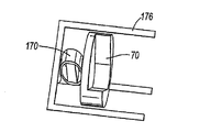
図12a、b及びcは、シングルアクチュエータ170がキヌタ骨15の裏側に取り付けられた実施形態の詳細を概略的に図示する。アクチュエータ170はクリップ172によりキヌタ骨15に固定される。脚13b、13cへの結合は、アブミ骨頭13aに配置及びロッド176により脚13b、13cに向けて付勢される、カプラ171を用いて達成される。図11に示した実施形態のように、この設計はアブミ骨の自然な動きの作用線に沿った振動を提供する。
FIGS. 12 a, b and c schematically illustrate details of an embodiment in which a
キヌタ骨クリップ172、カプラ171及びロッド176は、好ましくはチタニウム又はチタニウム合金からなり、キヌタ骨クリップ172は、超弾性特性若しくは形状記憶特性のどちらかを用いた形状記憶合金からなる。
側方アプローチを介した小骨への取付/接続 Attachment / connection to small bones via lateral approach
図13a及び13bは、アクチュエータ190が、図9a及び9bを参照して詳細に前述された、アクチュエータ130のフレーム部材135と略同じである、フレーム部材195を有する、好ましい実施形態の原寸に比例しない2つの概略図を示す。アクチュエータ190は、図9a及び9bを参照して詳細に前述された、アクチュエータ130の(シングルd33積層体を備える)圧電部材134と略同じであり、そしてフレーム部材195の空洞部199の凹部2007、209内への堅い圧入として確実に受容された、圧電部材を有する。圧電部材は明確化のため、図13a及び13bにおいて省略される。
FIGS. 13a and 13b are not to scale with the preferred embodiment, in which the
図13aは、アブミ骨クリップ191及びキヌタ骨クリップ192の形式で、側方から、アクチュエータ190をアブミ骨13及びキヌタ骨15に取り付けるための接続手段を示す。小骨を取り囲む限定された空間のために、側方アプローチが望まれる。フレーム部材195は、アブミ骨13へのアクチュエータ190の接続及び取付手段を備える2つの歯191a、191bを有する圧着取付フォークの形状を実質的に有する、アブミ骨クリップ191に固定して接続される第1のベース支持体206と共に設けられる。フレーム部材195は、キヌタ骨15へのアクチュエータ190の接続及び取付手段を備える2つの歯192a、192bを有する圧着取付フォークの形状を実質的に有する、キヌタ骨クリップ192に固定して接続される第2のベース支持体208と共に設けられる。フレーム部材195は、フレーム部材195の、凹部199内の圧電部材のための受容及び固定手段を各々提供される凹部207、209の提供により改良された、198、200に対して略直角に配置される一体化された第1及び第2の端部202、204、及びフレックステンショナル増幅器198、200を内蔵する。
FIG. 13 a shows connecting means for attaching the
図13bは、アブミ骨頭13aに圧着された歯191a、191bを用いたアブミ骨191、及びキヌタ骨15に圧着された歯192a、192bを用いたキヌタ骨192により耳小骨連鎖に取り付けられた、アクチュエータ190を図示する。
FIG. 13b shows the actuator attached to the ossicular chain with the
アブミ骨クリップ191及びキヌタ骨クリップ192は、好ましくは、チタニウム又はチタニウム合金から、又は超弾性特性若しくは形状記憶特性のどちらかを用いた形状記憶合金からなる。
The
この実施形態における利点は、アクチュエータ190が、フレーム部材195の空隙部199の凹部207、209に、圧電部材の第1及び第2の動作端を単に圧入することにより、確実に組み立てられることである。一旦組み立てられると、圧電部材は、フレーム部材195に接着されていないにもかかわらず、組立を維持するために動く傾向が常にある。アクチュエータ190はこのように本質的に安定した組立である。
The advantage in this embodiment is that the
アブミ骨クリップ及びキヌタ骨クリップは、好ましくは、チタニウム、チタニウム合金、又は超弾性特性若しくは形状記憶特性のどちらかを用いた形状記憶合金からなるスプリングクリップの形状をとる、スプリング手段を備える代わりの設計から成ることが理解される。 The stapes and quinuta bone clips are preferably alternative designs with spring means that take the form of spring clips made of titanium, titanium alloys, or shape memory alloys using either superelastic or shape memory properties. It is understood that
フレーム部材内に圧電部材を固定するための代替手段は、d33実施形態において通常、必須と見なされないため、図示されないが、部材の安定性を高めるために用いられ得る。しかしながら、d31モード実施例において、そのような代替固定手段は、適切な接着剤の使用、又は製造において形成された折りたたみ式タブの供給を含み、一体化された第1及び第2の端部の外面において最適な位置に配置される。可撓性ワイヤを用いるような更なる接続手段が想定されうる。 Alternative means for securing the piezoelectric member within the frame member are not normally shown in the d33 embodiment and are not shown, but can be used to increase the stability of the member. However, in the d31 mode embodiment, such alternative securing means include the use of a suitable adhesive or the supply of folding tabs formed in manufacturing, with integrated first and second end portions. It is arranged at an optimal position on the outer surface. Further connection means can be envisaged, such as using a flexible wire.
d33圧電部材が用いられるとき、前述のように、利点は、電気信号により作動されたときに圧電部材が伸張するという特徴を備え、その伸張は、変位の間にフレーム部材を押圧し、(公開された新規なフレーム部材における凹部の提供を超える)補助的な固定手段を用いる必要性を除去する。人体に埋め込むためのような挑戦的な環境において使用するためのアクチュエータの構造的完全性に対するこの重大な強化は、せん断荷重接着剤固定組立を頼りにする、プーリアらに付与された米国特許第6629922号明細書において公開されたもののような、先行技術によるアクチュエータを用いてなしえない。 When a d33 piezoelectric member is used, as described above, the advantage comprises the feature that the piezoelectric member expands when actuated by an electrical signal, which extension presses the frame member during displacement, (publicly Eliminates the need to use auxiliary fastening means (beyond providing a recess in the new frame member made). This significant enhancement to the structural integrity of actuators for use in challenging environments, such as for implantation in the human body, is based on US Pat. No. 6,629,922 to Puglia et al., Which relies on shear load adhesive fastening assemblies. It is not possible to use actuators according to the prior art, such as those published in the specification.
本発明によるアクチュエータのための音情報信号及び電力は、バッテリ、蓄電池、又は例えばコンデンサのような蓄電装置である電源を用いて、アクチュエータへの直接配線により供給されうることが理解される。 It is understood that the sound information signal and power for the actuator according to the present invention can be supplied by direct wiring to the actuator using a power source that is a battery, a storage battery, or a power storage device such as a capacitor.
有利なことに、本発明によるアクチュエータは、周辺環境から一又は二以上のその部品を隔離するためのハウジング、コーティング又はカバー手段と共に提供されうる。ハウジング手段は適切な金属又はプラスチックの筐体又は膜の形態をとりうる。 Advantageously, the actuator according to the invention may be provided with a housing, coating or cover means for isolating one or more of its parts from the surrounding environment. The housing means may take the form of a suitable metal or plastic housing or membrane.
アクチュエータ試験結果 Actuator test results
図14は、前述の計算において参照された寸法及び他の特性を有する、本発明によるアクチュエータに対する実験結果を図示する。圧電積層体は、1ボルトのピークトゥピークの印加電圧で、約8.1nmの変位をそれ自体与える。図10(キヌタ骨クリップがない)において図示されたように実質的に配置される取付手段によるアクチュエータ出力変位は、共鳴により20kHz以下で62.8nm(ゲイン=7.75)及び8kHz以下で46.3nm(ゲイン=5.7)以下の平均変位と共に、1kHz以下で38.5nm(ゲイン=4.75)である。鼓膜における90dBSPLの音刺激での標準のアブミ骨変位は、高い周波数では減少して、1kHz以下で約20nmである。 FIG. 14 illustrates experimental results for an actuator according to the present invention having the dimensions and other characteristics referenced in the above calculations. The piezoelectric laminate itself provides a displacement of about 8.1 nm with an applied voltage of 1 volt peak-to-peak. The actuator output displacement due to the mounting means arranged substantially as illustrated in FIG. 10 (without the Kinuta bone clip) is 62.8 nm (gain = 7.75) below 20 kHz and 46. It is 38.5 nm (gain = 4.75) at 1 kHz or less, with an average displacement of 3 nm (gain = 5.7) or less. Standard stapes displacement at 90 dBSPL sound stimulation in the tympanic membrane decreases at high frequencies and is about 20 nm below 1 kHz.
本発明は限定された数の好ましい実施形態に対する適切な参照を用いて説明されたが、本発明の変形及び修正が、特許請求の範囲において定義された本発明の範囲から逸脱することなく成立することは、いわゆる当業者にとって明らかである。 While this invention has been described with appropriate reference to a limited number of preferred embodiments, variations and modifications of this invention can be made without departing from the scope of this invention as defined in the claims. This will be apparent to those skilled in the art.
34 略長形圧電部材
36 略長形圧電部材
38 フレックステンショナル増幅器
42 第1のフレーム端部
44 第2のフレーム端部
46 ベース支持体
34 Substantially
Claims (17)
前記圧電部材の変位を増幅するための1以上のフレックステンショナル増幅要素を備えるフレーム部材であって、第1及び第2のフレーム端部が前記圧電部材の第1及び第2の動作端面を受容することにより、前記第1及び第2のフレーム端部が前記圧電部材に取り付けられたとき前記圧電部材の長手方向軸に対して略直角に延びるように、1以上のフレックステンショナル増幅要素の各々が前記第1及び第2のフレーム端部と一体となり、かつ前記第1及び第2のフレーム端部を接続する、フレーム部材とを備え、
少なくとも1つの前記フレックステンショナル増幅要素はベース支持手段に設けられ、
キヌタ骨及びアブミ骨のうちの1つに前記圧電部材を固定するため、前記ベース支持手段がクリップ手段に取り付けられる
人体の中耳に埋め込まれる補聴器のための、及びキヌタ骨に対してアブミ骨を動かすためのアクチュエータ。A substantially elongated piezoelectric member having first and second operating end faces, wherein the end face extends substantially perpendicular to the longitudinal axis of the piezoelectric member;
A frame member comprising one or more flexural amplifying elements for amplifying displacement of the piezoelectric member, wherein the first and second frame end portions receive the first and second operating end faces of the piezoelectric member. Each of the one or more flexural amplification elements such that when the first and second frame ends are attached to the piezoelectric member, they extend substantially perpendicular to the longitudinal axis of the piezoelectric member. Comprising a frame member that is integral with the first and second frame ends and connects the first and second frame ends;
At least one of the flexural amplification elements is provided on a base support means;
The base support means is attached to the clip means for securing the piezoelectric member to one of the Kinuta bone and Abumi bone. For the hearing aid implanted in the middle ear of the human body, and the Abumi bone to the Kinuta bone. Actuator for moving.
前記圧電部材の変位を増幅するため、1以上のフレックステンショナル増幅要素を備えるフレーム部材を設けるステップと、
前記圧電部材と前記フレーム部材とを組み立てるステップとを備え、
前記フレックステンショナル増幅要素は、第1及び第2のフレーム端部と一体となり、かつ第1及び第2のフレーム端部を接続し、前記第1及び第2のフレーム端部は、前記第1及び第2のフレーム端部が前記圧電部材の第1及び第2の動作端面を受容することにより、前記圧電部材に取り付けられたとき、前記圧電部材の長手方向軸に対して略直角に延び、
少なくとも1つの前記フレックステンショナル増幅要素は、キヌタ骨及びアブミ骨の1つに前記圧電部材を固定するためのクリップ手段に取り付けられるベース支持手段に設けられる、
人体の中耳に埋め込む補聴器、及びキヌタ骨に対してアブミ骨を動かすためのアクチュエータを形成する方法。Providing a substantially elongated piezoelectric member having first and second operating end faces, the end face extending substantially perpendicular to the longitudinal axis of the piezoelectric member;
Providing a frame member comprising one or more flexural amplification elements to amplify the displacement of the piezoelectric member;
Assembling the piezoelectric member and the frame member,
The flexural amplifying element is integral with the first and second frame ends and connects the first and second frame ends, and the first and second frame ends are the first and second frame ends. And the second frame end receives the first and second operating end faces of the piezoelectric member so that when attached to the piezoelectric member, it extends substantially perpendicular to the longitudinal axis of the piezoelectric member;
At least one of the flexural amplification elements is provided on a base support means attached to a clip means for securing the piezoelectric member to one of a quinuta bone and a stapes bone.
A method of forming a hearing aid embedded in the middle ear of a human body and an actuator for moving the stapes relative to the quinuta bone.
Applications Claiming Priority (3)
| Application Number | Priority Date | Filing Date | Title |
|---|---|---|---|
| GBGB0500616.8A GB0500616D0 (en) | 2005-01-13 | 2005-01-13 | Hearing implant |
| GB0500616.8 | 2005-01-13 | ||
| PCT/GB2006/000119 WO2006075169A1 (en) | 2005-01-13 | 2006-01-13 | Hearing implant |
Publications (2)
| Publication Number | Publication Date |
|---|---|
| JP2008526416A JP2008526416A (en) | 2008-07-24 |
| JP5011126B2 true JP5011126B2 (en) | 2012-08-29 |
Family
ID=34224511
Family Applications (1)
| Application Number | Title | Priority Date | Filing Date |
|---|---|---|---|
| JP2007550843A Active JP5011126B2 (en) | 2005-01-13 | 2006-01-13 | Hearing implant |
Country Status (14)
| Country | Link |
|---|---|
| US (1) | US8864645B2 (en) |
| EP (1) | EP1845919B1 (en) |
| JP (1) | JP5011126B2 (en) |
| CN (1) | CN101128172B (en) |
| AT (1) | ATE481064T1 (en) |
| AU (1) | AU2006205655B2 (en) |
| BR (1) | BRPI0606251A2 (en) |
| CA (1) | CA2594761C (en) |
| DE (1) | DE602006016914D1 (en) |
| DK (1) | DK1845919T3 (en) |
| ES (1) | ES2354144T3 (en) |
| GB (1) | GB0500616D0 (en) |
| RU (1) | RU2007131471A (en) |
| WO (1) | WO2006075169A1 (en) |
Families Citing this family (71)
| Publication number | Priority date | Publication date | Assignee | Title |
|---|---|---|---|---|
| US8401212B2 (en) | 2007-10-12 | 2013-03-19 | Earlens Corporation | Multifunction system and method for integrated hearing and communication with noise cancellation and feedback management |
| US7668325B2 (en) | 2005-05-03 | 2010-02-23 | Earlens Corporation | Hearing system having an open chamber for housing components and reducing the occlusion effect |
| US8295523B2 (en) | 2007-10-04 | 2012-10-23 | SoundBeam LLC | Energy delivery and microphone placement methods for improved comfort in an open canal hearing aid |
| US7867160B2 (en) | 2004-10-12 | 2011-01-11 | Earlens Corporation | Systems and methods for photo-mechanical hearing transduction |
| US7796769B2 (en) | 2006-05-30 | 2010-09-14 | Sonitus Medical, Inc. | Methods and apparatus for processing audio signals |
| GB2449114A (en) | 2007-05-11 | 2008-11-12 | Sentient Medical Ltd | Middle ear implant with piezoelectric actuator acting on stapes footplate |
| US8401213B2 (en) | 2008-03-31 | 2013-03-19 | Cochlear Limited | Snap-lock coupling system for a prosthetic device |
| DK2301261T3 (en) | 2008-06-17 | 2019-04-23 | Earlens Corp | Optical electromechanical hearing aids with separate power supply and signal components |
| US8396239B2 (en) | 2008-06-17 | 2013-03-12 | Earlens Corporation | Optical electro-mechanical hearing devices with combined power and signal architectures |
| KR101568451B1 (en) | 2008-06-17 | 2015-11-11 | 이어렌즈 코포레이션 | Optical electro-mechanical hearing devices with combined power and signal architectures |
| KR100999690B1 (en) * | 2008-07-08 | 2010-12-08 | 단국대학교 산학협력단 | Trans-tympanic Vibration Member and Installation Apparatus for Implantable Hearing Aids |
| US8262729B2 (en) * | 2008-07-08 | 2012-09-11 | Enteroptyx | Dynamic ossicular prosthesis |
| WO2010033933A1 (en) | 2008-09-22 | 2010-03-25 | Earlens Corporation | Balanced armature devices and methods for hearing |
| CN102598712A (en) * | 2009-06-05 | 2012-07-18 | 音束有限责任公司 | Optically coupled acoustic middle ear implant systems and methods |
| US9544700B2 (en) | 2009-06-15 | 2017-01-10 | Earlens Corporation | Optically coupled active ossicular replacement prosthesis |
| CN102640435B (en) | 2009-06-18 | 2016-11-16 | 伊尔莱茵斯公司 | Optical coupled cochlea implantation system and method |
| EP2443843A4 (en) | 2009-06-18 | 2013-12-04 | SoundBeam LLC | Eardrum implantable devices for hearing systems and methods |
| CN102598715B (en) | 2009-06-22 | 2015-08-05 | 伊尔莱茵斯公司 | optical coupling bone conduction device, system and method |
| WO2011005500A2 (en) | 2009-06-22 | 2011-01-13 | SoundBeam LLC | Round window coupled hearing systems and methods |
| WO2010151647A2 (en) * | 2009-06-24 | 2010-12-29 | SoundBeam LLC | Optically coupled cochlear actuator systems and methods |
| GB0910908D0 (en) * | 2009-06-24 | 2009-08-05 | Sentient Medical Ltd | Coupling apparatus |
| WO2010151636A2 (en) | 2009-06-24 | 2010-12-29 | SoundBeam LLC | Optical cochlear stimulation devices and methods |
| GB0910906D0 (en) * | 2009-06-24 | 2009-08-05 | Sentient Medical Ltd | Coupling apparatus |
| US20110144414A1 (en) * | 2009-10-01 | 2011-06-16 | Ototronix, Llc | Middle ear implant and method |
| AU2010301027B2 (en) | 2009-10-02 | 2014-11-06 | Soundmed, Llc | Intraoral appliance for sound transmission via bone conduction |
| DE102009051057B4 (en) | 2009-10-28 | 2019-05-29 | Technische Universität Dresden | Implantable sensor-actuator converter module for apparative hearing rehabilitation in the middle ear |
| CN102754456B (en) * | 2009-11-24 | 2015-11-25 | Med-El电气医疗器械有限公司 | For the implantable microphone of hearing assistance system |
| WO2011090974A1 (en) * | 2010-01-21 | 2011-07-28 | Vibrant Med-El Hearing Technology Gmbh | Incus replacement partial ossicular replacement prosthesis |
| EP2543198A4 (en) * | 2010-03-02 | 2015-05-20 | Vibrant Med El Hearing Tech | Hearing system |
| EP2571465A2 (en) * | 2010-05-17 | 2013-03-27 | Advanced Bionics AG | Implantable hearing aid and system and method for implanting the same |
| US20120165597A1 (en) * | 2010-08-03 | 2012-06-28 | Sonitus Medical, Inc. | Implantable piezoelectric polymer film microphone |
| WO2012021424A1 (en) * | 2010-08-09 | 2012-02-16 | #3248362 Nova Scotia Limited | Personal listening device |
| JP2013539351A (en) | 2010-10-08 | 2013-10-17 | ソリダゴ ソシエテ ア レスポンサビリテ リミテ | Implantable actuators for hearing aid applications |
| WO2012088187A2 (en) | 2010-12-20 | 2012-06-28 | SoundBeam LLC | Anatomically customized ear canal hearing apparatus |
| WO2011029960A2 (en) | 2011-01-04 | 2011-03-17 | Advanced Bionics Ag | Hearing instrument for round window stimulation |
| WO2012108309A1 (en) * | 2011-02-07 | 2012-08-16 | 株式会社村田製作所 | Displacement member, driving member, actuator, and driving apparatus |
| DE102011013895B4 (en) | 2011-03-10 | 2020-08-27 | Technische Universität Dresden | Implantable sensor-actuator-converter module for hearing rehabilitation according to DE 10 2009 051 057 B4 |
| CN102274098B (en) * | 2011-05-16 | 2013-06-19 | 上海华聆人工耳医疗科技有限公司 | Prebending-type artificial cochlear electrode |
| WO2012157691A1 (en) * | 2011-05-17 | 2012-11-22 | 株式会社村田製作所 | Planar speaker and av device |
| CN102404678A (en) * | 2011-11-03 | 2012-04-04 | 上海交通大学 | Actuator for hearing compensation and hearing aid device with the same |
| KR101296714B1 (en) | 2011-11-10 | 2013-08-20 | 경북대학교 산학협력단 | Round window driving vibrator with middle ear characteristics and hearing aid using the same |
| US9258656B2 (en) * | 2011-12-09 | 2016-02-09 | Sophono, Inc. | Sound acquisition and analysis systems, devices and components for magnetic hearing aids |
| US9066189B2 (en) | 2012-04-26 | 2015-06-23 | Med-El Elektromedizinische Geraete Gmbh | Non-pressure sensitive implantable microphone |
| CN102836018B (en) * | 2012-09-17 | 2015-04-29 | 中国矿业大学 | Artificial auditory ossicle for treating mixed hearing damage |
| CN102908227A (en) * | 2012-11-16 | 2013-02-06 | 上海力声特医学科技有限公司 | Artificial cochlea implanting device with fixing members |
| US10034103B2 (en) | 2014-03-18 | 2018-07-24 | Earlens Corporation | High fidelity and reduced feedback contact hearing apparatus and methods |
| US9998837B2 (en) * | 2014-04-29 | 2018-06-12 | Cochlear Limited | Percutaneous vibration conductor |
| WO2016011044A1 (en) | 2014-07-14 | 2016-01-21 | Earlens Corporation | Sliding bias and peak limiting for optical hearing devices |
| CN107113515B (en) * | 2014-11-12 | 2019-04-30 | Med-El电气医疗器械有限公司 | Processus brevis incudis attachment for implanted floating converter |
| US9924276B2 (en) | 2014-11-26 | 2018-03-20 | Earlens Corporation | Adjustable venting for hearing instruments |
| CN104799971A (en) * | 2015-04-28 | 2015-07-29 | 张景 | Implant-type hearing-aid device wirelessly powered and capable of prompting electric quantity |
| CN104796828B (en) * | 2015-05-04 | 2018-05-01 | 歌尔股份有限公司 | A kind of loudspeaker module |
| CN104902422A (en) * | 2015-05-04 | 2015-09-09 | 上海交通大学 | Hearing compensation actuator capable of bidirectional positioning |
| US10130807B2 (en) | 2015-06-12 | 2018-11-20 | Cochlear Limited | Magnet management MRI compatibility |
| US20160381473A1 (en) | 2015-06-26 | 2016-12-29 | Johan Gustafsson | Magnetic retention device |
| US10917730B2 (en) * | 2015-09-14 | 2021-02-09 | Cochlear Limited | Retention magnet system for medical device |
| US20170095202A1 (en) | 2015-10-02 | 2017-04-06 | Earlens Corporation | Drug delivery customized ear canal apparatus |
| US10178483B2 (en) | 2015-12-30 | 2019-01-08 | Earlens Corporation | Light based hearing systems, apparatus, and methods |
| US10492010B2 (en) | 2015-12-30 | 2019-11-26 | Earlens Corporations | Damping in contact hearing systems |
| US11350226B2 (en) | 2015-12-30 | 2022-05-31 | Earlens Corporation | Charging protocol for rechargeable hearing systems |
| WO2017139891A1 (en) * | 2016-02-17 | 2017-08-24 | Dalhousie University | Piezoelectric inertial actuator |
| CN109952771A (en) | 2016-09-09 | 2019-06-28 | 伊尔兰斯公司 | Contact hearing system, device and method |
| WO2018093733A1 (en) | 2016-11-15 | 2018-05-24 | Earlens Corporation | Improved impression procedure |
| CN106714061B (en) * | 2016-11-30 | 2019-06-18 | 中国矿业大学 | A kind of adjustable round window excitation type actuator of pose |
| US11595768B2 (en) | 2016-12-02 | 2023-02-28 | Cochlear Limited | Retention force increasing components |
| US20180352348A1 (en) * | 2017-06-06 | 2018-12-06 | Sonitus Technologies Inc. | Bone conduction device |
| WO2019173470A1 (en) | 2018-03-07 | 2019-09-12 | Earlens Corporation | Contact hearing device and retention structure materials |
| WO2019199680A1 (en) | 2018-04-09 | 2019-10-17 | Earlens Corporation | Dynamic filter |
| US20210176574A1 (en) * | 2018-10-22 | 2021-06-10 | Cochlear Limited | Linear transducer in a flapping and bending apparatus |
| JP7434571B2 (en) | 2020-01-17 | 2024-02-20 | シェンツェン・ショックス・カンパニー・リミテッド | Microphones and electronic devices that include them |
| CN112291686B (en) * | 2020-10-29 | 2022-04-01 | 维沃移动通信有限公司 | Wearable device |
Family Cites Families (69)
| Publication number | Priority date | Publication date | Assignee | Title |
|---|---|---|---|---|
| US2397569A (en) * | 1943-09-13 | 1946-04-02 | Eureka Williams Corp | Machine gun recharger |
| US3277433A (en) * | 1963-10-17 | 1966-10-04 | William J Toulis | Flexural-extensional electromechanical transducer |
| US3594514A (en) * | 1970-01-02 | 1971-07-20 | Medtronic Inc | Hearing aid with piezoelectric ceramic element |
| US3764748A (en) * | 1972-05-19 | 1973-10-09 | J Branch | Implanted hearing aids |
| GB1578854A (en) * | 1976-02-27 | 1980-11-12 | Victor Company Of Japan | Stereophonic sound reproduction system |
| JPS52125301A (en) * | 1976-04-13 | 1977-10-21 | Victor Co Of Japan Ltd | Signal processing circuit |
| JPS53114201U (en) * | 1977-02-18 | 1978-09-11 | ||
| DE2844979C2 (en) | 1978-10-16 | 1989-08-31 | Juval Dr.-Ing. 8000 München Mantel | Hearing aid |
| JPS60154800A (en) | 1984-01-24 | 1985-08-14 | Eastern Electric Kk | Hearing aid |
| US4624672A (en) * | 1984-03-15 | 1986-11-25 | Edmundas Lenkauskas | Coiled wire prosthesis for complete or partial ossicular reconstruction |
| JPS6142284A (en) | 1984-08-03 | 1986-02-28 | Nec Kansai Ltd | Displacement increasing device |
| US4729366A (en) * | 1984-12-04 | 1988-03-08 | Medical Devices Group, Inc. | Implantable hearing aid and method of improving hearing |
| DE3508830A1 (en) | 1985-03-13 | 1986-09-18 | Robert Bosch Gmbh, 7000 Stuttgart | Hearing aid |
| US5015225A (en) * | 1985-05-22 | 1991-05-14 | Xomed, Inc. | Implantable electromagnetic middle-ear bone-conduction hearing aid device |
| US4774515A (en) * | 1985-09-27 | 1988-09-27 | Bo Gehring | Attitude indicator |
| US4759070A (en) * | 1986-05-27 | 1988-07-19 | Voroba Technologies Associates | Patient controlled master hearing aid |
| JP2935266B2 (en) * | 1987-05-11 | 1999-08-16 | ジャンポルスキー、アーサー | Paradoxical hearing aids |
| US4809708A (en) * | 1987-08-12 | 1989-03-07 | Nicolet Instrument Corporation | Method and apparatus for real bar measurements |
| US4845688A (en) * | 1988-03-21 | 1989-07-04 | Image Acoustics, Inc. | Electro-mechanical transduction apparatus |
| US4901353A (en) * | 1988-05-10 | 1990-02-13 | Minnesota Mining And Manufacturing Company | Auditory prosthesis fitting using vectors |
| US4957478A (en) * | 1988-10-17 | 1990-09-18 | Maniglia Anthony J | Partially implantable hearing aid device |
| US5303306A (en) * | 1989-06-06 | 1994-04-12 | Audioscience, Inc. | Hearing aid with programmable remote and method of deriving settings for configuring the hearing aid |
| DE4104359A1 (en) * | 1991-02-13 | 1992-08-20 | Implex Gmbh | CHARGING SYSTEM FOR IMPLANTABLE HOERHILFEN AND TINNITUS MASKERS |
| FR2675372B1 (en) | 1991-04-19 | 1998-12-18 | Guy Charvin | SELF-ADJUSTABLE OSSICULAR PROSTHESIS OF THE MIDDLE EAR. |
| US5233665A (en) * | 1991-12-17 | 1993-08-03 | Gary L. Vaughn | Phonetic equalizer system |
| US5173944A (en) * | 1992-01-29 | 1992-12-22 | The United States Of America As Represented By The Administrator Of The National Aeronautics And Space Administration | Head related transfer function pseudo-stereophony |
| US5531787A (en) * | 1993-01-25 | 1996-07-02 | Lesinski; S. George | Implantable auditory system with micromachined microsensor and microactuator |
| JP2606069B2 (en) * | 1993-04-22 | 1997-04-30 | 日本電気株式会社 | Piezoelectric element displacement amplification mechanism and driving method thereof |
| US5325436A (en) * | 1993-06-30 | 1994-06-28 | House Ear Institute | Method of signal processing for maintaining directional hearing with hearing aids |
| US5913815A (en) * | 1993-07-01 | 1999-06-22 | Symphonix Devices, Inc. | Bone conducting floating mass transducers |
| US5456654A (en) * | 1993-07-01 | 1995-10-10 | Ball; Geoffrey R. | Implantable magnetic hearing aid transducer |
| US5436975A (en) * | 1994-02-02 | 1995-07-25 | Qsound Ltd. | Apparatus for cross fading out of the head sound locations |
| US5825894A (en) * | 1994-08-17 | 1998-10-20 | Decibel Instruments, Inc. | Spatialization for hearing evaluation |
| RU2096027C1 (en) | 1995-06-05 | 1997-11-20 | Юрий Петрович Ульянов | Method for improving audition |
| US5729077A (en) * | 1995-12-15 | 1998-03-17 | The Penn State Research Foundation | Metal-electroactive ceramic composite transducer |
| EP0868830A4 (en) | 1995-12-20 | 2006-03-22 | K S Himpp | Virtual electroacoustic audiometry for unaided, simulated aided, and aided hearing evaluation |
| AU710983B2 (en) * | 1996-02-15 | 1999-10-07 | Armand P. Neukermans | Improved biocompatible transducers |
| WO1997032385A1 (en) | 1996-03-01 | 1997-09-04 | Njc Innovations | Charging and/or signal transmission system comprising a light source coacting with photovoltaic cells |
| US5899847A (en) * | 1996-08-07 | 1999-05-04 | St. Croix Medical, Inc. | Implantable middle-ear hearing assist system using piezoelectric transducer film |
| US5879283A (en) * | 1996-08-07 | 1999-03-09 | St. Croix Medical, Inc. | Implantable hearing system having multiple transducers |
| US5707338A (en) * | 1996-08-07 | 1998-01-13 | St. Croix Medical, Inc. | Stapes vibrator |
| US6001129A (en) * | 1996-08-07 | 1999-12-14 | St. Croix Medical, Inc. | Hearing aid transducer support |
| DE29701534U1 (en) | 1997-01-30 | 1997-03-27 | Voit Sven | Device for holding two pieces of cutlery in tongs |
| US6315710B1 (en) * | 1997-07-21 | 2001-11-13 | St. Croix Medical, Inc. | Hearing system with middle ear transducer mount |
| US6325755B1 (en) * | 1997-08-07 | 2001-12-04 | St. Croix Medical, Inc. | Mountable transducer assembly with removable sleeve |
| US6137889A (en) * | 1998-05-27 | 2000-10-24 | Insonus Medical, Inc. | Direct tympanic membrane excitation via vibrationally conductive assembly |
| WO2000004287A1 (en) * | 1998-07-14 | 2000-01-27 | Csir | Generating displacement and thermoacoustic refrigerator |
| US6364825B1 (en) * | 1998-09-24 | 2002-04-02 | St. Croix Medical, Inc. | Method and apparatus for improving signal quality in implantable hearing systems |
| US6473513B1 (en) | 1999-06-08 | 2002-10-29 | Insonus Medical, Inc. | Extended wear canal hearing device |
| DE19923403C2 (en) * | 1999-05-21 | 2002-11-14 | Phonak Ag Staefa | Device for mechanically coupling an electromechanical hearing aid transducer that can be implanted in a mastoid cavity |
| DE19935029C2 (en) * | 1999-07-26 | 2003-02-13 | Phonak Ag Staefa | Implantable arrangement for mechanically coupling a driver part to a coupling point |
| DE19948375B4 (en) * | 1999-10-07 | 2004-04-01 | Phonak Ag | Arrangement for mechanically coupling a driver to a coupling point of the ossicle chain |
| US6554761B1 (en) * | 1999-10-29 | 2003-04-29 | Soundport Corporation | Flextensional microphones for implantable hearing devices |
| US6629922B1 (en) * | 1999-10-29 | 2003-10-07 | Soundport Corporation | Flextensional output actuators for surgically implantable hearing aids |
| DE10015421C2 (en) * | 2000-03-28 | 2002-07-04 | Implex Ag Hearing Technology I | Partially or fully implantable hearing system |
| DE10017332C2 (en) * | 2000-04-07 | 2002-04-18 | Daimler Chrysler Ag | Piezoelectric actuator for flap control on the rotor blade of a helicopter |
| US6671559B2 (en) * | 2001-01-23 | 2003-12-30 | Microphonics, Inc. | Transcanal, transtympanic cochlear implant system for the rehabilitation of deafness and tinnitus |
| US6875166B2 (en) * | 2001-09-06 | 2005-04-05 | St. Croix Medical, Inc. | Method for creating a coupling between a device and an ear structure in an implantable hearing assistance device |
| US20030097178A1 (en) * | 2001-10-04 | 2003-05-22 | Joseph Roberson | Length-adjustable ossicular prosthesis |
| GB0201574D0 (en) | 2002-01-24 | 2002-03-13 | Univ Dundee | Hearing aid |
| DE10331644B3 (en) | 2003-07-08 | 2005-01-20 | Technische Universität Dresden | ossicle prosthesis |
| DE202004001008U1 (en) * | 2004-01-23 | 2004-04-01 | Heinz Kurz Gmbh Medizintechnik | ossicle prosthesis |
| AT7627U1 (en) * | 2004-02-26 | 2005-06-27 | Verdichter Oe Ges M B H | REFRIGERANT COMPRESSOR |
| US7867160B2 (en) * | 2004-10-12 | 2011-01-11 | Earlens Corporation | Systems and methods for photo-mechanical hearing transduction |
| DE202006002196U1 (en) * | 2005-07-21 | 2006-04-27 | Heinz Kurz Gmbh Medizintechnik | ossicle prosthesis |
| US20080065002A1 (en) * | 2006-09-07 | 2008-03-13 | Neurosystec Corporation | Catheter for Localized Drug Delivery and/or Electrical Stimulation |
| KR100859979B1 (en) * | 2007-07-20 | 2008-09-25 | 경북대학교 산학협력단 | Implantable middle ear hearing device with tube type vibration transducer |
| KR100931209B1 (en) * | 2007-11-20 | 2009-12-10 | 경북대학교 산학협력단 | Easy-to-install garden-driven vibration transducer and implantable hearing aid using it |
| DE202007017910U1 (en) | 2007-12-21 | 2008-03-13 | Heinz Kurz Gmbh Medizintechnik | Modular Middle Ear Full Prosthesis |
-
2005
- 2005-01-13 GB GBGB0500616.8A patent/GB0500616D0/en not_active Ceased
-
2006
- 2006-01-13 DE DE602006016914T patent/DE602006016914D1/en active Active
- 2006-01-13 AT AT06700906T patent/ATE481064T1/en active
- 2006-01-13 US US11/795,137 patent/US8864645B2/en active Active
- 2006-01-13 BR BRPI0606251-2A patent/BRPI0606251A2/en not_active IP Right Cessation
- 2006-01-13 CA CA2594761A patent/CA2594761C/en active Active
- 2006-01-13 ES ES06700906T patent/ES2354144T3/en active Active
- 2006-01-13 WO PCT/GB2006/000119 patent/WO2006075169A1/en active Application Filing
- 2006-01-13 JP JP2007550843A patent/JP5011126B2/en active Active
- 2006-01-13 EP EP06700906A patent/EP1845919B1/en active Active
- 2006-01-13 CN CN200680005709.4A patent/CN101128172B/en active Active
- 2006-01-13 AU AU2006205655A patent/AU2006205655B2/en active Active
- 2006-01-13 DK DK06700906.8T patent/DK1845919T3/en active
- 2006-01-13 RU RU2007131471/14A patent/RU2007131471A/en not_active Application Discontinuation
Also Published As
| Publication number | Publication date |
|---|---|
| CA2594761C (en) | 2014-10-07 |
| AU2006205655B2 (en) | 2011-10-20 |
| DE602006016914D1 (en) | 2010-10-28 |
| US20090043149A1 (en) | 2009-02-12 |
| GB0500616D0 (en) | 2005-02-23 |
| ES2354144T3 (en) | 2011-03-10 |
| RU2007131471A (en) | 2009-02-20 |
| EP1845919A1 (en) | 2007-10-24 |
| DK1845919T3 (en) | 2011-01-24 |
| US8864645B2 (en) | 2014-10-21 |
| EP1845919B1 (en) | 2010-09-15 |
| CA2594761A1 (en) | 2006-07-20 |
| ATE481064T1 (en) | 2010-10-15 |
| JP2008526416A (en) | 2008-07-24 |
| CN101128172A (en) | 2008-02-20 |
| BRPI0606251A2 (en) | 2009-06-09 |
| CN101128172B (en) | 2010-06-23 |
| AU2006205655A1 (en) | 2006-07-20 |
| WO2006075169A1 (en) | 2006-07-20 |
Similar Documents
| Publication | Publication Date | Title |
|---|---|---|
| JP5011126B2 (en) | Hearing implant | |
| JP3710483B2 (en) | Implantable hearing aid | |
| US6161046A (en) | Totally implantable cochlear implant for improvement of partial and total sensorineural hearing loss | |
| AU778293B2 (en) | At least partially implantable hearing system for rehabilitation of a hearing disorder | |
| US6005955A (en) | Middle ear transducer | |
| US9020174B2 (en) | Bone conduction device having an integrated housing and vibrator mass | |
| US6629922B1 (en) | Flextensional output actuators for surgically implantable hearing aids | |
| US5707338A (en) | Stapes vibrator | |
| EP2786432B1 (en) | An energy harvesting cochlear implant | |
| US9497555B2 (en) | Implantable middle ear transducer having improved frequency response | |
| EP2156702B1 (en) | Middle ear implant actuator | |
| US7297101B2 (en) | Method and apparatus for minimally invasive placement of sensing and driver assemblies to improve hearing loss | |
| Park et al. | Comparisons of electromagnetic and piezoelectric floating-mass transducers in human cadaveric temporal bones | |
| US20130116497A1 (en) | Coupling Systems For Implantable Prosthesis Components | |
| EP2533738A1 (en) | Hearing aid comprising an intra-cochlear actuator | |
| Wang et al. | A micropower miniature piezoelectric actuator for implantable middle ear hearing device | |
| WO1999008480A2 (en) | Middle ear transducer | |
| Mills et al. | In vitro study of a multi-layer piezoelectric crystal attic hearing implant |
Legal Events
| Date | Code | Title | Description |
|---|---|---|---|
| A621 | Written request for application examination |
Free format text: JAPANESE INTERMEDIATE CODE: A621 Effective date: 20081225 |
|
| A131 | Notification of reasons for refusal |
Free format text: JAPANESE INTERMEDIATE CODE: A131 Effective date: 20110201 |
|
| A601 | Written request for extension of time |
Free format text: JAPANESE INTERMEDIATE CODE: A601 Effective date: 20110428 |
|
| A602 | Written permission of extension of time |
Free format text: JAPANESE INTERMEDIATE CODE: A602 Effective date: 20110511 |
|
| A601 | Written request for extension of time |
Free format text: JAPANESE INTERMEDIATE CODE: A601 Effective date: 20110527 |
|
| A602 | Written permission of extension of time |
Free format text: JAPANESE INTERMEDIATE CODE: A602 Effective date: 20110606 |
|
| A521 | Request for written amendment filed |
Free format text: JAPANESE INTERMEDIATE CODE: A523 Effective date: 20110701 |
|
| A131 | Notification of reasons for refusal |
Free format text: JAPANESE INTERMEDIATE CODE: A131 Effective date: 20120110 |
|
| A521 | Request for written amendment filed |
Free format text: JAPANESE INTERMEDIATE CODE: A523 Effective date: 20120405 |
|
| TRDD | Decision of grant or rejection written | ||
| A01 | Written decision to grant a patent or to grant a registration (utility model) |
Free format text: JAPANESE INTERMEDIATE CODE: A01 Effective date: 20120508 |
|
| A01 | Written decision to grant a patent or to grant a registration (utility model) |
Free format text: JAPANESE INTERMEDIATE CODE: A01 |
|
| A61 | First payment of annual fees (during grant procedure) |
Free format text: JAPANESE INTERMEDIATE CODE: A61 Effective date: 20120604 |
|
| R150 | Certificate of patent or registration of utility model |
Ref document number: 5011126 Country of ref document: JP Free format text: JAPANESE INTERMEDIATE CODE: R150 Free format text: JAPANESE INTERMEDIATE CODE: R150 |
|
| FPAY | Renewal fee payment (event date is renewal date of database) |
Free format text: PAYMENT UNTIL: 20150608 Year of fee payment: 3 |
|
| R250 | Receipt of annual fees |
Free format text: JAPANESE INTERMEDIATE CODE: R250 |
|
| R250 | Receipt of annual fees |
Free format text: JAPANESE INTERMEDIATE CODE: R250 |
|
| R250 | Receipt of annual fees |
Free format text: JAPANESE INTERMEDIATE CODE: R250 |
|
| S111 | Request for change of ownership or part of ownership |
Free format text: JAPANESE INTERMEDIATE CODE: R313113 |
|
| S531 | Written request for registration of change of domicile |
Free format text: JAPANESE INTERMEDIATE CODE: R313531 |
|
| R350 | Written notification of registration of transfer |
Free format text: JAPANESE INTERMEDIATE CODE: R350 |
|
| R250 | Receipt of annual fees |
Free format text: JAPANESE INTERMEDIATE CODE: R250 |
|
| R250 | Receipt of annual fees |
Free format text: JAPANESE INTERMEDIATE CODE: R250 |
|
| R250 | Receipt of annual fees |
Free format text: JAPANESE INTERMEDIATE CODE: R250 |
|
| R250 | Receipt of annual fees |
Free format text: JAPANESE INTERMEDIATE CODE: R250 |
|
| R250 | Receipt of annual fees |
Free format text: JAPANESE INTERMEDIATE CODE: R250 |
|
| R250 | Receipt of annual fees |
Free format text: JAPANESE INTERMEDIATE CODE: R250 |