JP4991069B2 - Linear drive system used in plasma processing systems - Google Patents
Linear drive system used in plasma processing systems Download PDFInfo
- Publication number
- JP4991069B2 JP4991069B2 JP2001550778A JP2001550778A JP4991069B2 JP 4991069 B2 JP4991069 B2 JP 4991069B2 JP 2001550778 A JP2001550778 A JP 2001550778A JP 2001550778 A JP2001550778 A JP 2001550778A JP 4991069 B2 JP4991069 B2 JP 4991069B2
- Authority
- JP
- Japan
- Prior art keywords
- gear
- gears
- processing system
- drive assembly
- plasma processing
- Prior art date
- Legal status (The legal status is an assumption and is not a legal conclusion. Google has not performed a legal analysis and makes no representation as to the accuracy of the status listed.)
- Expired - Lifetime
Links
- 238000012545 processing Methods 0.000 title claims description 196
- 239000000758 substrate Substances 0.000 claims description 103
- 238000000034 method Methods 0.000 claims description 37
- 230000008569 process Effects 0.000 claims description 28
- 238000012546 transfer Methods 0.000 claims description 11
- 238000005530 etching Methods 0.000 claims description 10
- 239000000463 material Substances 0.000 claims description 7
- 230000005684 electric field Effects 0.000 claims description 4
- 238000003672 processing method Methods 0.000 claims 1
- 238000007740 vapor deposition Methods 0.000 claims 1
- 230000001965 increasing effect Effects 0.000 description 9
- 230000008901 benefit Effects 0.000 description 7
- 230000007423 decrease Effects 0.000 description 7
- 230000008878 coupling Effects 0.000 description 5
- 238000010168 coupling process Methods 0.000 description 5
- 238000005859 coupling reaction Methods 0.000 description 5
- 238000000151 deposition Methods 0.000 description 5
- 230000008021 deposition Effects 0.000 description 5
- 238000013459 approach Methods 0.000 description 4
- 238000001020 plasma etching Methods 0.000 description 4
- 230000035945 sensitivity Effects 0.000 description 4
- 238000010586 diagram Methods 0.000 description 3
- 239000011521 glass Substances 0.000 description 3
- 150000002500 ions Chemical class 0.000 description 3
- 238000004519 manufacturing process Methods 0.000 description 3
- 230000007246 mechanism Effects 0.000 description 3
- 230000007935 neutral effect Effects 0.000 description 3
- 239000004065 semiconductor Substances 0.000 description 3
- VYPSYNLAJGMNEJ-UHFFFAOYSA-N Silicium dioxide Chemical compound O=[Si]=O VYPSYNLAJGMNEJ-UHFFFAOYSA-N 0.000 description 2
- XUIMIQQOPSSXEZ-UHFFFAOYSA-N Silicon Chemical compound [Si] XUIMIQQOPSSXEZ-UHFFFAOYSA-N 0.000 description 2
- 230000008859 change Effects 0.000 description 2
- 238000005229 chemical vapour deposition Methods 0.000 description 2
- 230000003247 decreasing effect Effects 0.000 description 2
- 238000013461 design Methods 0.000 description 2
- 238000006073 displacement reaction Methods 0.000 description 2
- 239000002184 metal Substances 0.000 description 2
- 229910052751 metal Inorganic materials 0.000 description 2
- 238000005240 physical vapour deposition Methods 0.000 description 2
- 238000000623 plasma-assisted chemical vapour deposition Methods 0.000 description 2
- 238000006467 substitution reaction Methods 0.000 description 2
- 230000001360 synchronised effect Effects 0.000 description 2
- 229910052581 Si3N4 Inorganic materials 0.000 description 1
- 230000003213 activating effect Effects 0.000 description 1
- 239000006227 byproduct Substances 0.000 description 1
- 238000005266 casting Methods 0.000 description 1
- 238000006243 chemical reaction Methods 0.000 description 1
- 238000004140 cleaning Methods 0.000 description 1
- 238000011109 contamination Methods 0.000 description 1
- 238000005137 deposition process Methods 0.000 description 1
- 238000007599 discharging Methods 0.000 description 1
- 238000009826 distribution Methods 0.000 description 1
- 238000001312 dry etching Methods 0.000 description 1
- 238000001125 extrusion Methods 0.000 description 1
- 238000005242 forging Methods 0.000 description 1
- 230000005484 gravity Effects 0.000 description 1
- 230000001939 inductive effect Effects 0.000 description 1
- 238000009616 inductively coupled plasma Methods 0.000 description 1
- 238000001746 injection moulding Methods 0.000 description 1
- 239000000314 lubricant Substances 0.000 description 1
- 238000012423 maintenance Methods 0.000 description 1
- 238000012544 monitoring process Methods 0.000 description 1
- 239000003921 oil Substances 0.000 description 1
- 238000005086 pumping Methods 0.000 description 1
- 238000011160 research Methods 0.000 description 1
- 230000004044 response Effects 0.000 description 1
- 229910052710 silicon Inorganic materials 0.000 description 1
- 239000010703 silicon Substances 0.000 description 1
- 235000012239 silicon dioxide Nutrition 0.000 description 1
- 239000000377 silicon dioxide Substances 0.000 description 1
- HQVNEWCFYHHQES-UHFFFAOYSA-N silicon nitride Chemical compound N12[Si]34N5[Si]62N3[Si]51N64 HQVNEWCFYHHQES-UHFFFAOYSA-N 0.000 description 1
- 238000004544 sputter deposition Methods 0.000 description 1
- 230000000087 stabilizing effect Effects 0.000 description 1
- -1 that is Substances 0.000 description 1
- 239000010409 thin film Substances 0.000 description 1
Images

Classifications
-
- H—ELECTRICITY
- H01—ELECTRIC ELEMENTS
- H01J—ELECTRIC DISCHARGE TUBES OR DISCHARGE LAMPS
- H01J37/00—Discharge tubes with provision for introducing objects or material to be exposed to the discharge, e.g. for the purpose of examination or processing thereof
- H01J37/32—Gas-filled discharge tubes
- H01J37/32431—Constructional details of the reactor
- H01J37/32623—Mechanical discharge control means
-
- H—ELECTRICITY
- H01—ELECTRIC ELEMENTS
- H01J—ELECTRIC DISCHARGE TUBES OR DISCHARGE LAMPS
- H01J37/00—Discharge tubes with provision for introducing objects or material to be exposed to the discharge, e.g. for the purpose of examination or processing thereof
- H01J37/32—Gas-filled discharge tubes
- H01J37/32431—Constructional details of the reactor
- H01J37/32532—Electrodes
- H01J37/32568—Relative arrangement or disposition of electrodes; moving means
Landscapes
- Physics & Mathematics (AREA)
- Engineering & Computer Science (AREA)
- Plasma & Fusion (AREA)
- Chemical & Material Sciences (AREA)
- Analytical Chemistry (AREA)
- Plasma Technology (AREA)
- Drying Of Semiconductors (AREA)
- Chemical Vapour Deposition (AREA)
Description
【0001】
【発明の背景】
本発明は、ICの製造に使用される半導体基板またはフラットパネルディスプレイに使用されるパネル(例えば、ガラスやプラスチックなど)などの基板を処理するための装置および方法に関する。より詳しくは、本発明は、基板の処理に関連する部品を移動させるための改良された方法および装置に関する。
【0002】
プラズマ処理システムが出回るようになってしばらくに経つ。誘導結合プラズマソース、電子サイクロトロン共鳴(ECR)ソース、容量性ソースなどを利用するプラズマ処理システムは、半導体基板および表示パネルを処理するために、長年に渡って様々な度合いで導入され採用されている。代表的なプラズマ処理の適用例では、まず、処理チャンバ内に処理用のソースガス(エッチャントガスまたはデポジションソースガス)を導入する。次に、エネルギを供給し、処理用のソースガスからプラズマを発生させる。発生したプラズマは、追加のエネルギによって維持される。追加のエネルギは、例えば、静電結合や、誘導結合、マイクロ波を介した結合などの種々の周知の方法でプラズマに結合される。そして、プラズマは、例えば、基板上の薄膜の選択的なエッチングまたは堆積などの処理に利用される。
【0003】
デポジションでは、基板の表面(ガラスパネルまたはウエハなどの表面)上に材料を堆積させる。例えば、基板の表面上には、ケイ素、二酸化ケイ素、窒化ケイ素、金属などの堆積層が形成される。これに対して、エッチングは、基板の表面上の既定の領域から材料を選択的に除去するために採用される。例えば、基板の層に、バイアや、コンタクト、トレンチなどのエッチング形状が形成される。
【0004】
基板を処理する際に、エンジニアが改善に務める最も重要なパラメータの1つは、処理の均一性である。ここで、処理の均一性は、基板表面全体の均一性や、同じ処理チャンバ内で処理される異なる基板間の均一性、異なる処理チャンバ内で処理される異なる基板間の均一性を意味する。処理の均一性が高い場合には、例えば、基板上の異なる点での処理速度と共に、同じ生産工程を経る異なる基板間の処理速度も、ほぼ等しいことが期待される。いずれの場合であっても、同じ基板上で過度に処理される領域と処理が不十分な領域とが生じたり、基板毎に処理が異なったりする可能性は低い。処理の均一性は歩留まりの重要な決定要因であるため、処理の均一性が高レベルであれば、メーカで必要となるコストは低下する傾向にある。
【0005】
多くの適用例において、処理の均一性を維持することは困難である。これは、基板の処理に関連する種々のパラメータが変動するためである。例えば、ウエハ領域圧力(WAP:wafer area pressure)、すなわち、基板表面の周辺の圧力は、基板の近くで生じる温度変化が原因で、基板の処理中に変動し得る。当業者に周知なように、異なる基板間でWAPが高かったり低かったりする場合には、基板毎の処理パフォーマンスが非均一になる傾向がある。また、同じ基板であっても、異なる領域間でWAPが高かったり低かったりする場合には、基板表面の全体における処理パフォーマンスが非均一になる傾向がある。
【0006】
WAPを制御する技術の1つは、処理チャンバ内に閉じ込めリングを設けることである。閉じ込めリングは、一般に、処理対象の基板の上方に位置する活性領域において、基板を囲むように構成される。こうすれば、処理の範囲が限定されるため、WAPの均一性が高まる。この技術は、多くの適用例では上手く作用するが、他の多くの適用例では、1枚の基板を処理する場合や、1つの生産工程で複数の基板を処理する場合、異なるチャンバで処理する場合に生じるWAPの変動に適合させるために、順応的に変化可能な制御処理環境を提供することが望まれている。
【0007】
近年、排出コンダクタンスを調整可能な、それ故、WAPを調整可能な可動閉じ込めリングを提供する試みもなされた。この方法では、WAPが制御され、処理中に生じる変動が低減される。具体的なアプローチの1つでは、カムシステムを使用し、上部電極と下部電極との間で閉じ込めリングを上下に移動させる。このアプローチでは、表面に異なる高さを有する環状カムが、閉じ込めリングに接続されたプランジャ/バネ機構に垂直に係合する。カムが回転すると、カムの表面上の異なる高さに応じて、プランジャが上下に移動し、それに対応して閉じ込めリングも上下に移動する。カム機構は、閉じ込めリングと下部電極との間の間隙を制御することによって、排出ガスのコンダクタンスを調整でき、これによって基板の上方の活性領域のWAPを調整できるように、構成される。
【0008】
この技術は、概ね上手く作用するが、カムを使用する従来のアプローチでは、限られた範囲の圧力制御、低感度、低分解能(すなわち低精度)しか提供できないという問題がある。例えば、カムの表面に設けられる傾斜すなわち高さは、プランジャとカムとの境界によって制限される。これは、傾斜が大きすぎるとプランジャが引っ掛かるためである。結果として、プランジャが移動できる全体の距離は限られ、圧力制御の範囲も制限される。また、カムを使用する従来のアプローチでは、処理中に圧力を正確に変化させることができない。さらに、プランジャとカムとの境界が磨耗したり、バネが弾力性を失ったりして、システムの信頼度が低下する傾向がある。
【0009】
メーカの大きな関心事の1つは、処理ツールの所有コストである。所有コストには、例えば、システムを入手および維持するためのコストや、処理パフォーマンスを許容可能なレベルに維持するために必要なチャンバの洗浄頻度、システム部品の寿命などが含まれる。望ましい処理とは、所有コストとプロセスパラメータとの間でバランスを保ち、低コストで高品質の処理を達成できるような処理を、意味する場合が多い。さらに、基板上の特徴の小型化や、処理に対する要求の増大(例えば、微小寸法を小さくする、アスペクト比を高める、スループットを向上させるなど)に伴って、エンジニアは、低コストで高品質の処理を達成できる新しい方法および装置を常に模索している。
【0010】
以上から、基板の処理に関連する部品(すなわち閉じ込めリング)を移動させるための改良された方法および装置が必要とされていることが分かる。
【0011】
【発明の概要】
本発明の一実施形態は、基板を処理するためのプラズマ処理システムに関する。プラズマ処理システムは、基板の処理に関連する部品を備える。部品は、例えば、閉じ込めリングや電極である。プラズマ処理システムは、さらに、部品を直線方向に移動させるための歯車駆動アセンブリを備える。いくつかの実施形態では、歯車駆動アセンブリは、基板の上方の圧力を制御するために、閉じ込めリングを移動させるように構成されている。他の実施形態では、歯車駆動アセンブリは、複数の部品を移動させるように構成されている。好ましい一実施形態において、歯車駆動アセンブリは、第1の歯車と、第2の歯車と、位置決め部材と、を備える。第1の歯車は、第2の歯車を駆動するように構成されており、第2の歯車は、位置決め部材を直線方向に移動させるように構成されている。また、位置決め部材は、上記部品に取り付けられており、この結果、位置決め部材が直線方向に移動するときに、部品は移動する。
【0012】
本発明の別の実施形態は、基板を処理するためのプラズマ処理システムに関する。プラズマ処理システムは、処理チャンバ内に電場を発生させるための電極と、処理チャンバ内にプラズマを閉じ込めるための閉じ込めリングと、を備える。プラズマ処理システムは、さらに、閉じ込めリングまたは電極を移動させるための歯車駆動アセンブリを備える。歯車駆動アセンブリは、第1の歯車と、第2の歯車と、位置決め部材と、を少なくとも備える。第1の歯車は、第2の歯車を駆動するように構成されており、第2の歯車は、位置決め部材を所定の方向に移動させるように構成されている。位置決め部材は、閉じ込めリングまたは電極に取り付けられており、この結果、第1の位置決め部材が第2の歯車によって移動するときに、閉じ込めリングまたは電極は所定の方向に移動する。
【0013】
いくつかの実施形態では、閉じ込めリングの位置は、基板が処理のために処理チャンバ内に配置されたときに、閉じ込めリングと基板との間に、間隙を形成するように構成されている。この間隙は、排気ガスのコンダクタンスを制御するように構成されている。
【0014】
いくつかの実施形態では、第1の歯車と第2の歯車とは、処理チャンバによって回転可能に支持されている。また、第2の歯車は、第1の歯車に動作可能に係合している。さらに、第2の歯車は、軸と、軸に設けられた第1のねじ切り面と、を有する。また、位置決め部材は、直線方向の移動を提供するために、第2の歯車の第1のねじ切り面に移動可能に結合された第2のねじ切り面を有する。
【0015】
いくつかの実施形態では、歯車駆動アセンブリは、第1の歯車を回転させるための駆動装置を備える。駆動装置は、モータと、モータに回転可能に結合された駆動歯車と、を備える。駆動歯車は、第1の歯車に動作可能に係合している。モータが駆動歯車を回転させると、駆動歯車は第1の歯車を駆動して回転させ、第1の歯車は第2の歯車を駆動して回転させ、回転する第2の歯車は位置決め部材を直線方向に移動させる。
【0016】
他の実施形態では、歯車駆動アセンブリは、さらに、第3の歯車と、第2の位置決め部材と、を備える。第1の歯車は、第3の歯車を駆動するように構成されている。また、第3の歯車は、第2の位置決め部材を所定の方向に移動させるように構成されている。さらに、第2の位置決め部材は、閉じ込めリングまたは電極に取り付けられており、この結果、第2の位置決め部材が第3の歯車によって移動するときに、取り込めリングまたは電極は所定の方向に移動する。関連の実施形態では、歯車駆動アセンブリは、さらに、第2の歯車または第3の歯車を第1の歯車に対して係合させたり解放させたりするためのトランスファ歯車を備える。第2の歯車がトランスファ歯車に係合する場合には、第1の位置決め部材が所定の方向に移動し、第3の歯車がトランスファ歯車に係合する場合には、第2の位置決め部材が所定の方向に移動する。
【0017】
いくつかの実施形態では、第1の歯車と第2の歯車と第3の歯車とトランスファ歯車とは、処理チャンバによって回転可能に支持されている。トランスファ歯車は、第1の歯車に動作可能に係合している。第2の歯車は、軸と、軸に設けられた第1のねじ切り面と、を有する。第1の位置決め部材は、直線方向の移動を提供するために、第2の歯車の第1のねじ切り面に移動可能に結合された第2のねじ切り面を有する。第3の歯車は、軸と、軸に設けられた第1のねじ切り面と、を有し、第2の位置決め部材は、直線方向の移動を提供するために、第3の歯車の第1のねじ切り面に移動可能に結合された第2のねじ切り面を有する。
【0018】
本発明の別の実施形態は、基板の処理に関連する物体を移動させるための直線駆動アセンブリに関する。直線駆動アセンブリは、第1の歯車と、第1の歯車に動作可能に係合する第2の歯車と、を備える。また、直線駆動アセンブリは、第1の部分と第2の部分とを有する位置決め部材を備える。第1の部分は、第2の歯車に対して直線方向に移動可能に結合されており、第2の部分は、物体に取り付けられている。いくつかの実施形態では、位置決め部材は、一定のピッチを有する雄ねじ切り面を含み、第2の歯車は、雄ねじ切り面のピッチと同じピッチを有する雌ねじ切り面を含む。位置決め部材の雄ねじ切り面は、第2の歯車の雌ねじ切り面内に、回転可能に設けられている。他の実施形態では、位置決め部材は直線形の歯車(例えばラックピニオン装置)である。
【0019】
いくつかの実施形態では、直線駆動アセンブリは、第1の歯車を駆動するためのモータを備える。また、直線駆動アセンブリは、複数の第2の歯車と、複数の位置決め部材と、を備える。複数の第2の歯車と複数の位置決め部材とは、第1の歯車の周辺に対称的に間隔を空けた状態で設けられている。例えば、外歯車が用いられる場合には、第2の歯車は、対称的に間隔を空けた状態で第1の歯車の外周に設けられ、内歯車(例えばプラネタリ歯車)が用いられる場合には、第2の歯車は、対称的に間隔を空けた状態で第1の歯車の内周に設けられる。
【0020】
直線駆動アセンブリは、静電結合リアクタや、誘電結合リアクタ、ECRリアクタを含む種々のプラズマ処理システムにおいて使用可能である。関連の実施形態では、直線駆動アセンブリは、プラズマ処理システムの処理チャンバ内で閉じ込めリングを移動させるように構成可能である。また、直線駆動アセンブリは、プラズマ処理システムの処理チャンバ内または処理チャンバ外で電極を移動させるように構成可能である。
【0021】
【発明の実施の形態】
次に、添付図面に例示された幾つかの好ましい実施形態に関連して、本発明を詳細に説明する。以下の説明では、本発明が完全に理解されるように、多くの項目を特定している。しかしながら、当業者には明らかなように、本発明は、これらの項目の一部または全てを特定しなくても実施できる。また、本発明が不必要に不明瞭となるのを避けるため、周知の処理工程の詳細な説明は省略した。
【0022】
本発明は、基板の処理に関連する物体を、高度な移動制御を用いて移動させることができる直線駆動アセンブリを提供する。直線駆動アセンブリは、動作可能に互いに係合された複数の歯車を備える。直線駆動アセンブリは、また、所定の歯車セットに移動可能に結合され、かつ、可動物体に構造的に結合された複数の位置決め部材を備える。位置決め部材は、所定の歯車セットが回転するときに、物体を直線方向に移動させるように構成されている。具体的な一適用例では、位置決め部材は、所定の歯車セットの雌ねじと噛み合うように構成された雄ねじを有するシャフトである。所定の歯車セットが回転すると、この歯車の回転によって雌ねじが回転し、この結果、シャフトが直線方向に移動する。したがって、歯車およびねじの使用によって、物体の直線運動を高度に制御することができる。例えば、歯車/ねじ構成は、より高い分解能・感度・信頼度で、より正確な移動を可能にする。
【0023】
本発明の一実施形態は、処理の均一性を高度に制御することができるプラズマ処理システムに関する。プラズマ処理システムは、基板を処理するように構成されている。プラズマ処理システムは、処理用のプラズマの生成および維持の双方に利用される処理チャンバと、下部電極と、上部電極と、閉じ込めリングと、を備える。
【0024】
本発明の一態様に従えば、直線駆動アセンブリの直線運動は、処理中に、閉じ込めリングと下部電極との間の間隙を制御するように構成されている。具体的には、直線駆動アセンブリは、上部電極と下部電極との間で、閉じ込めリングを上下に移動させて、排出ガスのコンダクタンスを調整できるように設けられている。排出ガスのコンダクタンスを調整することによって、基板の上方の活性領域の圧力(すなわちWAP)が、処理に適した所望のレベルに維持される。したがって、処理中に、わずかな変化量で圧力が制御され、この結果、処理の均一性を高め、これによって基板のスループットを高め、デバイス故障を低減させ、処理対象の基板の全体的な生産性を向上させることができる。
【0025】
本発明の別の一態様に従えば、直線駆動アセンブリの直線運動は、処理中に、上部電極と基板との間の間隙を制御するように構成されている。具体的には、直線駆動アセンブリは、上部電極を上下に移動させて、基板の上方における活性領域の容積を調整するように設けられている。容積を調整することによって、プラズマ密度および圧力などのプラズマ処理に関連する種々のパレメータが、処理に適した所望のレベルに維持される。同様に、プラズマ密度および圧力は、処理中にわずかな変化量で制御され、この結果、処理の均一性を高め、これによって基板のスループットを高め、デバイス故障を低減させ、処理対象の基板の全体的な生産性を向上させることができる。
【0026】
本発明の別の一態様に従えば、直線駆動アセンブリの直線運動は、処理中に、閉じ込めリングと下部電極との間の間隙と、上部電極と基板との間の間隙とを、独立して制御するように構成されている。具体的な実施形態では、直線駆動アセンブリは、追加の歯車を備えるように再構成される。例えば、直線駆動アセンブリは、所定の歯車および位置決め部材からなる第2のセットを備える。所定の歯車および位置決め部材からなる第1のセットは、閉じ込めリングを移動させるように構成され、所定の歯車および位置決め部材からなる第2のセットは、上部電極を移動させるように構成される。また、所定の歯車を、第1の歯車に動作可能に係合させたり解放させたりするためのトランスファ歯車も備えられている。こうすれば、両方の間隙が制御され、プロセスエンジニアは、処理対象の基板周辺の処理条件をより良く制御することができる。
【0027】
好ましい一実施形態では、本発明は、カリフォルニア州フリーモント市のラムリサーチコーポレーションから市販されている静電結合型プラズマリアクタなどのプラズマリアクタにおいて実施される。以下では、静電結合型プラズマリアクタを図示して説明するが、本発明は、例えば、誘導結合型またはECRリアクタなどのプラズマを生成させるのに適した任意のプラズマリアクタにおいて実施可能である。
【0028】
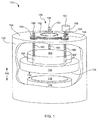
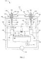
図1および図2は、本発明の一実施形態に従ってプラズマリアクタ100を示す概略図である。プラズマリアクタ100は、一般に、プラズマ処理チャンバ102を備える。チャンバ102内には、上部電極104および下部電極106が設けられている。上部電極104は、下部電極106の上方に設けられ、整合回路網(図面を簡略化するため図示せず)を介して、第1のRF(高周波)電源108に結合されている。第1のRF電源108は、上部電極104にRF(高周波)エネルギを供給するように構成されている。また、下部電極106は、第2のRF電源110に結合されており、第2のRF電源110は、下部電極106にRFエネルギを供給するように構成されている。
【0029】
上部電極104と下部電極106との間の間隙111は、一般に、処理中における活性領域の容積を決定する。したがって、間隙111の寸法は、圧力および/またはプラズマ密度などの種々のパラメータを制御できるように構成される。理論に縛られることは望ましくないが、プラズマ密度は、容積の減少に伴って増大し、容積の増大に伴って減少すると考えられる。当業者に周知のように、プラズマ密度は、例えば、エッチング速度などの処理速度に影響を及ぼし易い。したがって、間隙は、処理に適した所望の容積と所望のエッチング速度とのバランスが保たれるように、構成される。
【0030】
さらに、間隙111は、一般に、基板の上方の活性領域の圧力制御に重要であると考えられる。一般則として、圧力は容積に反比例するため、容積の減少は圧力の増大に対応し、容積の増大は圧力の減少に対応する。したがって、間隙111の寸法は、処理に適した所望の容積と所望の圧力とのバランスが保たれるように、構成されることが好ましい。
【0031】
また、プラズマリアクタ100は、下部電極106の上面に設けられたチャック112を備える。チャック112は、処理中に基板114を保持するように構成されている。チャック112は、例えば、基板114を静電力によって表面に固定するESC(静電)チャックであってもよい。また、基板114は、処理対象の加工物であり、例えば、エッチング、堆積、その他の処理が施される半導体基板や、フラットパネルディスプレイに処理されるガラスパネルであってもよい。
【0032】
プラズマチャンバ102内には、さらに、エッチャントソースガスなどのガス状のソース材料を上部電極と基板との間の活性領域中に放出するためのガスポート116が設けられている。図2に示すように、ガスポート116は、上部電極104内部に設けられる。また、処理チャンバの壁部と下部電極106の間には、一般に、処理中に形成された副産ガスを排出するための排気ポート118が設けられている。図2では、排気ポート118は、チャンバ102の底部に設けられたポンプ120に結合されている。ポンプ120は、一般に、チャンバ102内の圧力を適切に維持するように設けられている。一実装例では、ターボ分子ポンプが使用される。
【0033】
例えば、プラズマを生成するために、プロセスガスがガスポート116を介してチャンバに導入される。次に、電力が電極104,106に供給され、上部電極104と下部電極106との間に強い電場が形成される。この分野において周知のように、プロセスガスの中性ガス分子は、強い電場に曝されると電子を失い、正に帯電したイオンが残る。この結果、プラズマ中には、正電荷を帯びたイオンと、負電荷を帯びた電子と、中性ガスの分子とが、含まれる。また、基板の真上では、一般に、シース電圧が生成される。これは、基板に向かってイオンを加速させるため、中性の種と共に処理の反応を活性化させる。
【0034】
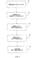
さらに詳しく説明するため、図4は、プラズマリアクタ(例えばプラズマリアクタ100)内での基板の処理に関係する関連動作の流れ図を示す。処理に先行して、まず、基板の出し入れを含む従来の前処理工程が実施される。代表的な処理は、通常、5つの工程を経る。第1の工程201は、処理チャンバを所望の圧力までポンピングすることを含む。第2の工程202は、プロセスガスを処理チャンバに流入させ、圧力を安定させることを含む。ガスが安定すると、第3の工程204において、プロセスガスからプラズマを発生させる。プラズマが発生すると、第4の工程206において、チャンバ内でプラズマを特定の圧力で安定させる。チャンバの圧力が安定すると、第5の工程208において、基板が処理される。
【0035】
図1および図2に戻って、プラズマ処理チャンバ100は、さらに、一般にプラズマを基板114の上方の領域に閉じ込めるように構成された閉じ込めリング130を備える。図2に示すように、閉じ込めリング130の第1の部分は、上部電極104の外周を囲むように配置され、第2の部分は、上部電極104と下部電極106の間の間隙111を囲むように配置されている。これによって、閉じ込めリング130は、基板114の上方の活性領域の少なくとも一部を囲む。閉じ込めリング130は、処理の均一性を高めるために、基板114の周辺において対称的に配置されている。
【0036】
図示するように、間隙132は、通常、閉じ込めリング130の下端134と下部電極106との間に形成される。間隙132は、一般に、上部電極104および閉じ込めリング130によって規定された容積中にプラズマを実質的に閉じ込めるとともに、排出ガスのコンダクタンスを制御するために、設けられる。閉じ込めリング130の下端は、下部電極106の上面に対して均一な間隔で(例えば平行に)設けられることが好ましい。こうすれば、基板114の表面におけるガスの分布を均一に維持することができる。
【0037】
間隙132の寸法は、一般に、処理中に活性領域から排出ガスが除去される速度を決定する。理論に縛られることは望ましくないが、間隙が小さすぎると、ガスの流れが妨げられるため、エッチング速度が不均一になり、基板の周囲に沿って微粒子汚染が生じると考えられる。また、間隙が大きすぎると、プラズマを適切な容積中に適切に閉じ込めることができず、エッチング速度が不均一になる(例えば不均一なプラズマ)と考えられる。さらに、一般に、間隙は、基板の上方の活性領域の圧力制御に重要であると考えられる。すなわち、圧力は排気速度に反比例するため、コンダクタンスの減少は圧力の増大に対応し、コンダクタンスの増大は圧力の減少に対応する。したがって、間隙の寸法は、所望のコンダクタンスと所望の圧力とのバランスを保つように、構成されることが好ましい。
【0038】
図1および図2には、上部電極104と下部電極106との間で、閉じ込めリング130を移動させるように構成された直線駆動アセンブリ150が、本発明の一実施形態に従って示されている。処理中に閉じ込めリング130を上下に移動させることによって、プラズマ処理チャンバ102から排出されるエッチャントソースガスのコンダクタンスが増減され、圧力が処理に適した所望の圧力範囲内に維持される。例えば、圧力を調整することによって、基板の処理中に生じる温度の変動に適合させ、この結果、基板間の均一性を維持することができる。さらに、直線駆動アセンブリ150は、基板114の出し入れのために閉じ込めリングを上下に移動させるように構成される。
【0039】
直線駆動アセンブリ150は、一般に、1つの第1の歯車152と、複数の第2の歯車154と、を備える。第1の歯車152と複数の第2の歯車154との双方は、処理チャンバ102のカバー156によって回転可能に支持されている。さらに、複数の第2の歯車154は、第1の歯車152に動作可能に係合している。また、直線駆動アセンブリ150は、第1の部分160と第2の部分162とをそれぞれ有する複数の位置決め部材158を備える。各位置決め部材158は、互いに平行である。第1の部分160は、それぞれ、第2の歯車154の1つに移動可能に結合しており、位置決め部材158を直線方向166に移動させることを可能にする。第2の部材162は、それぞれ、閉じ込めリング130に取り付けられている。図1に示すように、直線方向166は、基板114の上面によって形成される平面に垂直な方向である。また、位置決め部材158とカバー156との間には、一般に、シール175が設けられており、境界を塞ぎ、漏れを排除する。
【0040】
さらに、直線駆動アセンブリは、モータ161と、モータ161に取り付けられた駆動歯車163と、を備える。モータは、当業者に周知であり、簡略化のため説明を省略する。駆動歯車163は、第1の歯車152に動作可能に係合しており、モータが作動するときに第1の歯車152を駆動させるように構成されている。モータ161は駆動歯車163を駆動し、駆動歯車163は第1の歯車152を駆動し、第1の歯車152は複数の第2の歯車154を駆動し、複数の第2の歯車154は対応する位置決め部材158を直線方向166に移動させる。この結果、閉じ込めリング130は、上部電極104と下部電極106との間で直線方向166に移動する。
【0041】
直線状の経路に沿った位置決め部材158の移動方向は、一般に、第2の歯車154の回転方向によって決定される。例えば、直線駆動アセンブリ150は、第2の歯車154が時計回りに回転する場合には位置決め部材158を上方に移動させ、第2の歯車154が反時計回りに回転する場合には位置決め部材158を下方に移動させるように構成されている。
【0042】
図2を参照すると、複数の位置決め部材158は、複数の第2の歯車154にねじ込み可能に結合されている。すなわち、位置決め部材158と第2の歯車154とがねじで係合することによって、第2の歯車154が回転する場合に、位置決め部材158は直線方向に移動する。第2の歯車154は、一般に、雌ねじ切り面を有するナット部分170を備えており、位置決め部材158は、一般に、雄ねじ切り面を有するねじ山部分172を備えている。各位置決め部材158の雄ねじ切り面は、対応する第2の歯車154の雌ねじ切り面と噛み合うように構成されている。したがって、第2の歯車154が回転する場合には、位置決め部材158のねじ山部分172は、回転する第2の歯車154のナット部分170を通って移動する。ねじの利用による具体的な利点の1つは、ねじは常に係合しているため、非常に正確な移動が可能となることである。
【0043】
さらに、位置決め部材/第2の歯車構成は、一般に、ナット部分170が1回転する毎に、位置決め部材158がねじ山1つ分だけ移動するように構成されている。当業者に周知のように、ねじの長さ方向に沿って測定された隣接するねじ山の対応部分間の距離は、一般に、ピッチと呼ばれる。したがって、ナット部分170が1回転する毎に、位置決め部材158は1ピッチ分の距離だけ移動する。例えば、ねじ山が1インチあたり32個切られている場合には、第2の歯車(例えばナット部分170)が1回転する毎に、位置決め部材158は、1/32インチ移動する。なお、ねじ山の切り込みは、より高い分解能を備えるように構成されていてもよい。すなわち、1インチあたりに切り込むねじ山の数を増やせば、位置決め部材158をより細かな変位量で移動させることができ、この結果、圧力をより細かく調整することができる。例えば、1インチあたりの約10個から約40個のねじ山を有するねじが上手く作用する。なお、これは限定事項ではなく、1インチあたりのねじ山の数は、各処理チャンバの具体的な設計に従って変更可能である。
【0044】
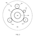
本発明の特徴をさらに説明するため、図3は、プラズマリアクタ100の直線駆動アセンブリ150の上面図を示す。前述したように、直線駆動アセンブリ150は、1つの第1の歯車152と、複数の第2の歯車154と、複数の位置決め部材158と、駆動歯車163と、を備える。複数の第2の歯車154と駆動歯車163とは、一般に、第1の歯車152の周辺に設けられる。第2の歯車154の動きは、互いに同期している。すなわち、移動方向(例えば時計回りまたは反時計回り)と移動量(例えば移動する歯の数)とは、同じである。
【0045】
ここでは、直線駆動アセンブリ150は、外平歯車(external spur gears)を使用するものとして、図示して説明している。しかしながら、異なるタイプの処理チャンバに適応したり、直線運動を可能にするために必要な他の外付けの要素に適合したりするために、他の歯車構造を採用してもよい。例えば、内歯車(例えばプラネタリ歯車)も上手く作用する。内歯車が用いられる場合には、複数の第2の歯車および駆動歯車は、第1の歯車の内周に設けられる。
【0046】
図3に示すように、直線駆動アセンブリ150は、3つの第2の歯車154と、3つの位置決め部材158と、を備えている。当業者に周知のように、平面は3点によって規定されるので、閉じ込めリングを移動させる位置決め部材は、3つ存在することが好ましい。3つの位置決め部材158は、閉じ込めリング130を、その重心に直交する方向に移動させるように構成されているため、閉じ込めリング130は、バランス良く水平な状態に維持される。図示するように、第2の歯車/位置決め部材構成は、それぞれ、第1の歯車152の周りに対称的に間隔を空けた状態で配置されており、各位置決め部材158は、対応する第2の歯車154の中心に軸配向されている。なお、本発明は、3つの位置決め部材に限定されず、バランスを保ちつつ閉じ込めリングを移動させるのに適した任意の数の位置決め部材を用いることが可能である。
【0047】
当業者に周知のように、全ての歯車を適切に噛み合わせるためには、すなわち、ズレを生じることなく回転させるためには、歯車は、ほぼ同じ寸法の類似の歯で構成される必要がある。さらに、噛み合った歯車同士が滑らかに、かつ、静かに移動するように、歯車と歯車との間には、通常、小さな隙間が設けられる。歯車アセンブリによる具体的な利点の1つは、歯車は常に噛み合わされているので、クリープすなわちズレが生じず、この結果、非常に正確な移動が可能となることである。
【0048】
直線駆動アセンブリの感度および分解能を決定する重要な要因の1つは、歯車の寸法(例えば歯)を適切に選択することにある。一般に、歯の数が多い程、分解能が高いと考えられている。すなわち、歯の数が多い程、位置決め部材によって移動される距離をより小さな変位量で変化させることができ、したがって、圧力をより細かく変化させることができる。本質的に、各歯車は、x歯数分解能を有する。より詳しくは、歯の数は、歯車を構成する個々のセグメントとして記述することができる。例えば、10個の歯を有する第2の歯車は、10個のセグメントに分割される。これらのセグメントは、第2の歯車の漸進的な動きに対応している。歯1個分だけ移動する場合には、第2の歯車も1セグメントだけ移動するため、第2の歯車の回転は1/10回転するのみである。第2の歯車と位置決め部材とは係合しているため、位置決め部材は、これに応じて1/10ピッチだけ移動する。ピッチが1/32インチである場合には、位置決め部材は、1/320インチ移動する。例えば、約10〜約48個の歯を有する第2の歯車は、上手く作用する。なお、これは限定事項ではなく、第2の歯車に設けられる歯の数は、各処理チャンバの具体的な設計に従って変更可能である。
【0049】
歯車は、金属やプラスチックなどの任意の適切な材料で形成可能であり、鋳造、鍛造、押出成形、射出成形などの任意の既知のプロセスを使用して製造可能である。しかしながら、歯車または処理チャンバのカバーが熱膨張を生じる場合(例えば温度が高い場合)には、熱膨張係数のほぼ等しい材料でこれらを形成する必要がある。こうすれば、歯車や処理チャンバのカバーは、ほぼ同じ速度で膨張する。これは、熱膨張が小さい場合には要因とならない。歯車間の隙間は、通常、熱膨張量よりも大きいためである。さらに、歯車間に潤滑剤すなわちオイルを用いることによって、熱膨張による影響を抑制し、噛み合っている歯車間の磨耗を低減させるようにしてもよい。
【0050】
前述のように、複数の歯車は、処理チャンバのカバーによって回転可能に支持されている。一実施形態では、歯車の自由な回転を可能にする軸受歯車が使用される。図3に示すように、第1の歯車152は、1組の軸受け180と連携した内周を有する同心環として構成されている。より具体的には、1組の軸受け180は、第1の歯車152の内周とカバー156の部分182との間に設けられている。したがって、カバー156の部分182は、ガスポート、センサ、マノメータなどの通路として使用可能である。軸受歯車は周知であり、簡略化のためこれ以上の説明は省略する。また、第2の歯車は、処理チャンバのカバーに固定されている。一実装例では、第2の歯車を処理チャンバのカバーに取り付けるために、スラスト軸受が使用される。
【0051】
直線駆動アセンブリ(例えば150)は、一般に、処理チャンバ内の圧力の変動を低減させるように構成された閉ループ制御システムの一部を構成している。例えば、プラズマ処理装置は、基板上方の活性領域の圧力を測定するための圧力センサと、測定された圧力をモニタするためのコントローラすなわちCPUと、を含むように構成されていてもよい。直線駆動アセンブリのモータと圧力センサとの双方は、コントローラに動作可能に結合されている。圧力センサは、測定された圧力に対応する電気圧力信号を生成するように構成されている。コントローラは、圧力センサから電気圧力信号を受信し、受信した信号に少なくとも部分的に基づく対応する電気制御信号をモータに送信するように構成されている。さらに、モータは、コントローラによって送信された電気制御信号を受信して、実行するように構成されている。電気制御信号は、一般に、モータの具体的な方向および漸進的な位置の変化に関係する。圧力センサとコントローラとモータとは、当該分野において周知であるため、詳細な説明は省略する。
【0052】
本発明の別の実施形態に従えば、直線駆動アセンブリの直線運動は、上部電極と基板との間の間隙を制御するように構成されている。この具体的な実施形態では、位置決め部材は、閉じ込めリングに代えて、上部電極に取り付けられる。このとき、直線駆動アセンブリは、上部電極を上下に移動させるように構成され、これによって、基板上方の活性領域の容積が調整される。容積を調整することによって、プラズマ密度や圧力などのプラズマ処理に関連した種々のパレメータが、処理に適した所望のレベルに維持される。
【0053】
本発明のこの態様の説明を容易にするため、図5は、処理チャンバ102内で上部電極104を移動させるように構成された直線駆動アセンブリ700を備えるプラズマリアクタ100を示す。この図において、直線駆動アセンブリ700は、図1〜図4に関連して既述した発明の教示内容に従って作成されているため、簡単な説明とする。
【0054】
直線駆動アセンブリ700は、一般に、1つの第1の歯車702と、複数の第2の歯車704と、を備える。第1の歯車702と複数の第2の歯車704との双方は、処理チャンバ102のカバー156によって回転可能に支持されている。さらに、複数の第2の歯車704は、第1の歯車702に動作可能に係合している。また、直線駆動アセンブリ700は、第1の部分710と第2の部分712とをそれぞれ有する複数の位置決め部材706を備える。第1の部分710は、第2の歯車704に対して直線方向166に移動可能に結合しており、第2の部分712は、上部電極104に取り付けられている。図示するように、直線方向166は、基板114の上面によって形成される平面に垂直な方向である。さらに、位置決め部材706は、第2の歯車704にねじ込み可能に結合されている。前述したように、位置決め部材706と第2の歯車704とがねじで係合することによって、第1の歯車702が回転する場合に、位置決め部材706は直線方向166に移動する。
【0055】
また、直線駆動アセンブリ700は、モータ161と、モータ161に取り付けられた駆動歯車163と、を備える。駆動歯車163は、第1の歯車702に動作可能に係合しており、モータ161が作動するときに第1の歯車702を駆動させるように構成されている。モータ161は駆動歯車163を駆動し、駆動歯車163は第1の歯車702を駆動し、第1の歯車702は複数の第2の歯車704を駆動し、複数の第2の歯車704は対応する位置決め部材706を直線方向166に移動させる。この結果、上部電極104は、直線方向166に移動する。
【0056】
以上では、直線駆動アセンブリは、閉じ込めリングまたは上部電極を移動させるものとして図示され説明されているが、異なるプロセスに適応できるように、他の部品を移動させるようにしてもよい。例えば、直線駆動アセンブリは、下部電極を移動させるために用いられていてもよい。なお、本発明は、処理チャンバ内の部品を移動させることに限定されない。例えば、直線駆動アセンブリは、チャンバの外側に設けられたアンテナや電極を移動させるために用いられていてもよい。このタイプのシステムが使用される場合には、直線駆動アセンブリは、一般に、図示するような処理チャンバのカバーに代えて、プラズマリアクタのフレームに結合される。また、直線駆動アセンブリは、1つの部品を移動させることに限定されず、複数の部品を移動させるのに使用することも可能である。例えば、直線駆動アセンブリは、複数の閉じ込めリングを移動させるように、あるいは、閉じ込めリングおよび上部電極などの複数の部品の組み合わせを移動させるように、構成されていてもよい。
【0057】
本発明の別の実施形態に従えば、直線駆動アセンブリの直線運動は、閉じ込めリングと上部電極との双方を移動させるように構成されている。こうすれば、処理に関連する種々のパラメータをより良く制御することが可能になる。例えば、閉じ込めリングと上部電極との双方を移動させることによって、基板上方の活性領域内の圧力およびプラズマ密度を変化させることができる。したがって、これらの物体のいずれかを移動させることによって、基板間の均一性を維持してもよい。
【0058】
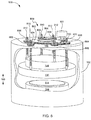
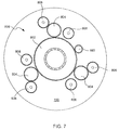
本発明のこの態様の説明を容易にするため、図6および図7は、処理チャンバ102内で複数の物体を移動させるように構成された直線駆動アセンブリ800を備えるプラズマリアクタ100を示す。この図では、直線駆動アセンブリ800は、図1〜図5に関連して既述した発明の教示内容に従って作成されている。そして、直線駆動アセンブリ800は、処理に関連する種々のパラメータを制御するために、上部電極104と下部電極106との間で閉じ込めリング130を移動させるように、かつ、処理チャンバ102内で上部電極104を移動させるように、構成されている(いずれも優れた移動制御が用いられる)。
【0059】
直線駆動アセンブリ800は、一般に、1つの第1の歯車802と、複数の第2の歯車804と、を備える。第1の歯車802と複数の第2の歯車804との双方は、処理チャンバ102のカバー156によって回転可能に支持されている。さらに、複数の第2の歯車804は、第1の歯車802に動作可能に係合している。また、直線駆動アセンブリ800は、複数の第3の歯車806と、複数の第4の歯車808と、を備えており、これらは、処理チャンバ102によって固定された状態で、かつ、回転可能に支持されている。第1の位置決め部材810のセットは、第3の歯車806のセットに移動可能に結合しており、第2の位置決め部材812のセットは、第4の歯車808のセットに移動可能に結合している。双方の位置決め部材810,812のセットは、直線方向166に回転可能に結合されている。図示するように、直線方向166は、基板114の上面によって形成される平面に垂直な方向である。さらに、第1の位置決め部材810のセットは、閉じ込めリング130に取り付けられており、第2の位置決め部材812のセットは、上部電極104に取り付けられている。
【0060】
さらに、第2の歯車804は、処理チャンバ102に移動可能に結合しており、第3の歯車806および第4の歯車808に対して係合したり離れたりするように構成されている。より具体的には、第2の歯車804は、処理チャンバ102のカバーの上に少なくとも2つの位置を有する。第1の位置(図示された位置)は、第2の歯車804を第3の歯車806に動作可能に係合させ、第2の位置は、第2の歯車804を第4の歯車808に動作可能に係合させる。一実施形態では、第2の歯車804は、カバー156に設けられた溝を通ってこれらの両位置間でスライドするように構成されている。この実施形態では、これらの両位置間で第2の歯車を移動させ、第3の歯車および第4の歯車に対して第2の歯車を接続したり非接続したりするために、クラッチが設けられている。一実装例では、クラッチは、第2の歯車804の係合および解放を自動的に実行する閉ループプロセスの一部として構成される。クラッチは、当該分野で周知であるため、詳細な説明は省略する。
【0061】
また、直線駆動アセンブリは、モータ161と、モータ161に取り付けられた駆動歯車163と、を備える。駆動歯車163は、第1の歯車802に動作可能に係合しており、モータ161が作動するときに第1の歯車802を駆動させるように構成されている。第2の歯車804が第3の歯車806と係合すると、モータ161は駆動歯車163を駆動し、駆動歯車163は第1の歯車802を駆動し、第1の歯車802は複数の第2の歯車804を駆動し、複数の第2の歯車804は複数の第3の歯車806を駆動し、第3の歯車は対応する位置決め部材810を直線方向166に移動させる。この結果、閉じ込めリング130は、上部電極104と下部電極106との間で直線方向166に移動する。第2の歯車804が第4の歯車808に係合すると、モータ161は駆動歯車163を駆動し、駆動歯車163は第1の歯車802を駆動し、第1の歯車802は複数の第2の歯車804を駆動し、複数の第2の歯車804は複数の第4の歯車808を駆動し、第4の歯車は対応する位置決め部材812を直線方向166に移動させる。この結果、上部電極102は、直線方向166に移動する。
【0062】
詳細には、第1の位置決め部材810のセットは、第3の歯車806にねじ入み可能に結合されており、第2の位置決め部材812は、第4の歯車808にねじ込み可能に結合されている。前述したように、位置決め部材と対応する歯車とがねじで係合することによって、対応する歯車が回転する場合に、位置決め部材は直線方向に移動する。
【0063】
さらに、複数の第2の歯車804と駆動歯車163とは、一般に、第1の歯車802の周辺に設けられる。したがって、第2の歯車の動きは、互いに同期している。すなわち、移動方向(例えば時計回りまたは反時計回り)と、移動量(例えば移動する歯の数)とは、同じである。さらに、第3の歯車806のセットは、一般に、第2の歯車804の近くに、かつ、閉じ込めリング130の上方に設けられており、第4の歯車808のセットは、一般に、第2の歯車804の近くに、かつ、上部電極102の上方に設けられている。図示するように、第3の歯車/位置決め部材構成および第4の歯車/位置決め部材構成は、それぞれ、第1の歯車の周りに対称的に間隔を空けた状態で配置され、各位置決め部材は、対応する歯車の中心に軸配向されている。
【0064】
図1〜図5で説明した直線駆動アセンブリと同様に、図6および図7で説明した直線駆動アセンブリは、歯車の歯の数および位置決め部材のピッチを調整することによって、高分解能に構成される。また、図6および図7の直線駆動アセンブリは、前述したように制御ループシステムの一部を構成していてもよい。
【0065】
以上から分かるように、本発明は、従来技術と比べて多くの利点を提供することができる。別の実施形態または実装例であっても、以下に挙げる1以上の利点を有する。
【0066】
本発明の利点の1つは、直線駆動アセンブリが高分解能、高感度、高信頼度の正確な移動を提供することである。この結果、閉じ込めリングや上部電極などの部品を、より広範囲の制御で移動させることができる。したがって、ウエハ領域圧力およびプラズマ密度などのパラメータを制御して、処理の均一性(すなわち基板表面全体の均一性および基板間の均一性)を高めることによって、基板のスループットを向上させ、デバイス故障を低減させ、処理対象の基板の全体的な生産性を高めることができる。
【0067】
本発明の他の利点は、コスト有効性である。例えば、本発明は、単一のモータのみを使用して、処理チャンバ内の複数の物体を移動させるように、構成される。本発明は、さらに、消耗部品(例えば磨耗)の量を減らすことができる。この結果、システムを取得および維持するコストが低減される。本発明の他の具体的な利点は、リアルタイムで制御が行われることである。つまり、1枚の基板の処理期間中に直線移動を実施することができる。
【0068】
以上では、本発明をいくつかの好ましい実施形態で説明したが、本発明の範囲内で、種々の代替、置き換え、および等価物が可能である。例えば、平歯車のみを図示して説明したが、ヘリカル歯車、山歯歯車、ウォーム歯車、傘歯車、扇形歯車、ベルト、および/または、チェーンなどの他の歯車構成を使用してもよい。また、位置決め部材/第2の歯車構成は、直線方向に移動するように構成されたラックピニオン歯車として構成されていてもよい。さらに、駆動歯車を有するモータのみを図示して説明したが、他の駆動機構を用いるようにしてもよい。例えば、モータは、第1の歯車に直接結合されていてもよいし、ベルトまたはチェーンを用いて間接的に結合されていてもよい。
【0069】
なお、本発明による方法および装置を実現する代替の方法が数多く存在する。例えば、直線駆動アセンブリは、閉じ込めリングおよび上部電極を移動させるように構成されたものとして説明されているが、下部電極などの他の物体を移動させるように構成されてもよい。さらに、物体を、基板に垂直な方向以外の直線方向に移動させてもよい。例えば、直線駆動アセンブリは、基板の表面に平行な方向に物体を移動させるために用いられてもよい。
【0070】
また、本発明は、エッチングまたはデポジションに適した任意のリアクタで使用可能である。例えば、本発明は、化学気相蒸着(CVD)やプラズマCVD(PECVD)、スパッタリングなどの物理蒸着(PVD)を含む適切で既知の任意のデポジションプロセスで使用可能である。さらに、本発明は、ドライエッチング、プラズマエッチング、反応性イオンエッチング(RIE)、磁気反応性イオンエッチング(MERIE)、電子サイクロトロン共鳴(ECR)などを含む適切で既知の任意のエッチングプロセスで使用可能である。
【0071】
したがって、添付した特許請求の範囲は、このような代替、置換、等価物の全てを本発明の真の趣旨および範囲内に含むものとして解釈される。
【図面の簡単な説明】
本発明は、同様の要素に同様の番号が与えられた添付図面において、限定的ではなく例示的に示される。
【図1】 本発明の一実施形態に従って、一部が除去された状態のプラズマリアクタを示す透視図である。
【図2】 図1のプラズマリアクタの側方断面図である。
【図3】 図1のプラズマリアクタの上方断面図である。
【図4】 本発明の一実施形態に従って、図1〜図3のプラズマリアクタ内での基板の処理に関係する関連工程を示す流れ図である。
【図5】 本発明の一実施形態に従って、一部が除去された状態のプラズマリアクタを示す透視図である。
【図6】 本発明の一実施形態に従って、一部が除去された状態のプラズマリアクタを示す透視図である。
【図7】 図6のプラズマリアクタの上方断面図である。
【符号の説明】
100…プラズマリアクタ
102…プラズマ処理チャンバ
104…上部電極
106…下部電極
108…第1のRF電源
110…第2のRF電源
111…間隙
112…チャック
114…基板
116…ガスポート
118…排気ポート
120…ポンプ
130…閉じ込めリング
132…間隙
134…閉じ込めリングの下端
150…直線駆動アセンブリ
152…第1の歯車
154…第2の歯車
156…処理チャンバのカバー
158…位置決め部材
160…位置決め部材の第1の部分
161…モータ
162…位置決め部材の第2の部分
163…駆動歯車
166…直線方向
170…第2の歯車のナット部分
172…位置決め部材のねじ山部分
175…シール
180…軸受け
182…カバーの部分
700…直線駆動アセンブリ
702…第1の歯車
704…第2の歯車
706…位置決め部材
710…位置決め部材の第1の部分
712…位置決め部材の第2の部分
800…直線駆動アセンブリ
802…第1の歯車
804…第2の歯車
806…第3の歯車
808…第4の歯車
810…第1の位置決め部材
812…第2の位置決め部材[0001]
BACKGROUND OF THE INVENTION
The present invention relates to an apparatus and method for processing a substrate such as a semiconductor substrate used in the manufacture of an IC or a panel (eg, glass, plastic, etc.) used in a flat panel display. More particularly, the present invention relates to an improved method and apparatus for moving parts associated with substrate processing.
[0002]
It's been a while since the plasma processing system came on the market. Plasma processing systems that use inductively coupled plasma sources, electron cyclotron resonance (ECR) sources, capacitive sources, and the like have been introduced and employed at various degrees over the years to process semiconductor substrates and display panels. . In a typical plasma processing application, first, a processing source gas (an etchant gas or a deposition source gas) is introduced into a processing chamber. Next, energy is supplied to generate plasma from a processing source gas. The generated plasma is maintained by additional energy. The additional energy is coupled to the plasma in a variety of well-known ways, such as electrostatic coupling, inductive coupling, and coupling via microwaves. The plasma is used for processing such as selective etching or deposition of a thin film on a substrate.
[0003]
In deposition, material is deposited on the surface of a substrate (a surface such as a glass panel or wafer). For example, a deposited layer of silicon, silicon dioxide, silicon nitride, metal or the like is formed on the surface of the substrate. In contrast, etching is employed to selectively remove material from predetermined areas on the surface of the substrate. For example, etching shapes such as vias, contacts, and trenches are formed in the substrate layer.
[0004]
When processing a substrate, one of the most important parameters that engineers strive to improve is process uniformity. Here, processing uniformity means uniformity of the entire substrate surface, uniformity between different substrates processed in the same processing chamber, and uniformity between different substrates processed in different processing chambers. When the uniformity of processing is high, for example, it is expected that the processing speeds at different points on the substrate as well as the processing speeds between different substrates through the same production process are almost equal. In any case, there is a low possibility that an area that is excessively processed and an area that is insufficiently processed are generated on the same substrate or that the processing is different for each substrate. Since the uniformity of processing is an important determinant of yield, if the processing uniformity is high, the cost required by the manufacturer tends to decrease.
[0005]
In many applications, it is difficult to maintain process uniformity. This is because various parameters related to substrate processing vary. For example, wafer area pressure (WAP), i.e., pressure around the substrate surface, may vary during processing of the substrate due to temperature changes that occur near the substrate. As is well known to those skilled in the art, when WAP is high or low between different substrates, the processing performance of each substrate tends to be non-uniform. Further, even if the same substrate is used, if the WAP is high or low between different regions, the processing performance on the entire substrate surface tends to be non-uniform.
[0006]
One technique for controlling WAP is to provide a confinement ring within the processing chamber. The confinement ring is generally configured to surround the substrate in an active region located above the substrate to be processed. In this way, the range of processing is limited, so the WAP uniformity is increased. This technique works well in many applications, but in many other applications it is processed in different chambers when processing a single substrate or when processing multiple substrates in one production process. It would be desirable to provide a control processing environment that can be adaptively changed to accommodate the WAP variations that occur in some cases.
[0007]
In recent years, attempts have also been made to provide movable confinement rings with adjustable drain conductance and hence with adjustable WAP. In this way, the WAP is controlled and variations that occur during processing are reduced. One specific approach uses a cam system to move the confinement ring up and down between the upper and lower electrodes. In this approach, annular cams with different heights on the surface engage perpendicularly to the plunger / spring mechanism connected to the confinement ring. As the cam rotates, the plunger moves up and down in response to different heights on the surface of the cam, and the confinement ring moves up and down accordingly. The cam mechanism is configured such that the conductance of the exhaust gas can be adjusted by controlling the gap between the confinement ring and the lower electrode, thereby adjusting the WAP of the active region above the substrate.
[0008]
Although this technique works generally well, the conventional approach using cams has the problem of providing only a limited range of pressure control, low sensitivity, and low resolution (ie, low accuracy). For example, the slope or height provided on the surface of the cam is limited by the boundary between the plunger and the cam. This is because the plunger is caught when the inclination is too large. As a result, the total distance that the plunger can travel is limited and the range of pressure control is also limited. Also, conventional approaches that use cams cannot accurately change pressure during processing. Furthermore, the reliability of the system tends to decrease because the boundary between the plunger and the cam is worn or the spring loses its elasticity.
[0009]
One of the major concerns of manufacturers is the cost of ownership of processing tools. Cost of ownership includes, for example, the cost to obtain and maintain the system, the frequency of chamber cleaning required to maintain process performance at an acceptable level, the lifetime of system components, and the like. Desirable processing often means processing that maintains a balance between cost of ownership and process parameters and that can achieve high quality processing at low cost. In addition, as features on the board become smaller and processing requirements increase (eg, smaller dimensions, higher aspect ratios, improved throughput, etc.), engineers are able to reduce the cost of high-quality processing. We are always looking for new methods and equipment that can achieve this.
[0010]
From the foregoing, it can be seen that there is a need for an improved method and apparatus for moving components (ie, confinement rings) associated with substrate processing.
[0011]
Summary of the Invention
One embodiment of the invention relates to a plasma processing system for processing a substrate. The plasma processing system includes components related to substrate processing. The component is, for example, a confinement ring or an electrode. The plasma processing system further comprises a gear drive assembly for moving the part in a linear direction. In some embodiments, the gear drive assembly is configured to move the confinement ring to control the pressure above the substrate. In other embodiments, the gear drive assembly is configured to move a plurality of parts. In a preferred embodiment, the gear drive assembly includes a first gear, a second gear, and a positioning member. The first gear is configured to drive the second gear, and the second gear is configured to move the positioning member in the linear direction. Further, the positioning member is attached to the component, and as a result, the component moves when the positioning member moves in the linear direction.
[0012]
Another embodiment of the invention relates to a plasma processing system for processing a substrate. The plasma processing system includes an electrode for generating an electric field within the processing chamber and a confinement ring for confining the plasma within the processing chamber. The plasma processing system further comprises a gear drive assembly for moving the confinement ring or electrode. The gear drive assembly includes at least a first gear, a second gear, and a positioning member. The first gear is configured to drive the second gear, and the second gear is configured to move the positioning member in a predetermined direction. The positioning member is attached to the confinement ring or electrode, so that when the first positioning member is moved by the second gear, the confinement ring or electrode moves in a predetermined direction.
[0013]
In some embodiments, the location of the confinement ring is configured to form a gap between the confinement ring and the substrate when the substrate is placed in the processing chamber for processing. This gap is configured to control the conductance of the exhaust gas.
[0014]
In some embodiments, the first gear and the second gear are rotatably supported by the processing chamber. The second gear is operatively engaged with the first gear. Furthermore, the second gear has a shaft and a first threaded surface provided on the shaft. The positioning member also has a second threaded surface movably coupled to the first threaded surface of the second gear to provide linear movement.
[0015]
In some embodiments, the gear drive assembly comprises a drive for rotating the first gear. The drive device includes a motor and a drive gear rotatably coupled to the motor. The drive gear is operatively engaged with the first gear. When the motor rotates the driving gear, the driving gear drives and rotates the first gear, the first gear drives and rotates the second gear, and the rotating second gear linearly moves the positioning member. Move in the direction.
[0016]
In other embodiments, the gear drive assembly further comprises a third gear and a second positioning member. The first gear is configured to drive the third gear. The third gear is configured to move the second positioning member in a predetermined direction. Further, the second positioning member is attached to the confinement ring or electrode so that when the second positioning member is moved by the third gear, the capture ring or electrode moves in a predetermined direction. In a related embodiment, the gear drive assembly further comprises a transfer gear for engaging or releasing the second gear or the third gear with respect to the first gear. When the second gear is engaged with the transfer gear, the first positioning member moves in a predetermined direction, and when the third gear is engaged with the transfer gear, the second positioning member is predetermined. Move in the direction of.
[0017]
In some embodiments, the first gear, the second gear, the third gear, and the transfer gear are rotatably supported by the processing chamber. The transfer gear is operatively engaged with the first gear. The second gear has a shaft and a first threaded surface provided on the shaft. The first positioning member has a second threaded surface movably coupled to the first threaded surface of the second gear to provide linear movement. The third gear has a shaft and a first threaded surface provided on the shaft, and the second positioning member provides a first movement of the third gear to provide linear movement. A second threaded surface is movably coupled to the threaded surface.
[0018]
Another embodiment of the invention relates to a linear drive assembly for moving an object associated with the processing of a substrate. The linear drive assembly includes a first gear and a second gear operably engaged with the first gear. The linear drive assembly also includes a positioning member having a first portion and a second portion. The first portion is coupled to the second gear to be movable in a linear direction, and the second portion is attached to the object. In some embodiments, the positioning member includes a male threaded surface having a constant pitch, and the second gear includes a female threaded surface having the same pitch as the pitch of the male threaded surface. The male threaded surface of the positioning member is rotatably provided in the female threaded surface of the second gear. In other embodiments, the positioning member is a linear gear (eg, a rack and pinion device).
[0019]
In some embodiments, the linear drive assembly comprises a motor for driving the first gear. The linear drive assembly includes a plurality of second gears and a plurality of positioning members. The plurality of second gears and the plurality of positioning members are provided in a state of being symmetrically spaced around the first gear. For example, when an external gear is used, the second gear is provided on the outer periphery of the first gear in a symmetrically spaced state, and when an internal gear (for example, a planetary gear) is used, The second gear is provided on the inner periphery of the first gear in a symmetrically spaced state.
[0020]
The linear drive assembly can be used in various plasma processing systems including electrostatic coupling reactors, dielectric coupling reactors, ECR reactors. In a related embodiment, the linear drive assembly can be configured to move the confinement ring within the processing chamber of the plasma processing system. The linear drive assembly can also be configured to move the electrodes within or outside the processing chamber of the plasma processing system.
[0021]
DETAILED DESCRIPTION OF THE INVENTION
The present invention will now be described in detail with reference to a few preferred embodiments illustrated in the accompanying drawings. In the following description, numerous items are identified so that the invention may be fully understood. However, as will be apparent to those skilled in the art, the present invention may be practiced without identifying some or all of these items. In order to avoid unnecessarily obscuring the present invention, detailed descriptions of well-known processing steps have been omitted.
[0022]
The present invention provides a linear drive assembly that can move objects associated with the processing of a substrate using advanced movement control. The linear drive assembly includes a plurality of gears that are operatively engaged with each other. The linear drive assembly also includes a plurality of positioning members movably coupled to the predetermined gear set and structurally coupled to the movable object. The positioning member is configured to move the object in a linear direction when a predetermined gear set rotates. In one specific application, the positioning member is a shaft having an external thread configured to mesh with an internal thread of a predetermined gear set. When a predetermined gear set rotates, the internal thread is rotated by the rotation of the gear, and as a result, the shaft moves in a linear direction. Therefore, the linear motion of the object can be highly controlled by the use of gears and screws. For example, the gear / screw configuration allows for more accurate movement with higher resolution, sensitivity, and reliability.
[0023]
One embodiment of the present invention relates to a plasma processing system capable of highly controlling process uniformity. The plasma processing system is configured to process a substrate. The plasma processing system includes a processing chamber utilized for both generation and maintenance of plasma for processing, a lower electrode, an upper electrode, and a confinement ring.
[0024]
According to one aspect of the invention, the linear motion of the linear drive assembly is configured to control the gap between the confinement ring and the bottom electrode during processing. Specifically, the linear drive assembly is provided to adjust the exhaust gas conductance by moving the confinement ring up and down between the upper electrode and the lower electrode. By adjusting the exhaust gas conductance, the pressure in the active region above the substrate (ie, WAP) is maintained at a desired level suitable for processing. Thus, during processing, the pressure is controlled with a small amount of variation, resulting in increased processing uniformity, thereby increasing substrate throughput, reducing device failure, and overall productivity of the substrate being processed. Can be improved.
[0025]
According to another aspect of the invention, the linear motion of the linear drive assembly is configured to control the gap between the top electrode and the substrate during processing. Specifically, the linear drive assembly is provided to adjust the volume of the active region above the substrate by moving the upper electrode up and down. By adjusting the volume, various parameters associated with plasma processing, such as plasma density and pressure, are maintained at desired levels suitable for processing. Similarly, plasma density and pressure are controlled with small variations during processing, resulting in increased processing uniformity, thereby increasing substrate throughput, reducing device failure, and the overall substrate being processed. Productivity can be improved.
[0026]
According to another aspect of the present invention, the linear movement of the linear drive assembly independently causes a gap between the confinement ring and the lower electrode and a gap between the upper electrode and the substrate during processing. Configured to control. In a specific embodiment, the linear drive assembly is reconfigured to include additional gears. For example, the linear drive assembly includes a second set of predetermined gears and positioning members. A first set of predetermined gear and positioning member is configured to move the confinement ring, and a second set of predetermined gear and positioning member is configured to move the upper electrode. A transfer gear is also provided for operably engaging and releasing a predetermined gear with the first gear. In this way, both gaps are controlled, and the process engineer can better control the processing conditions around the substrate to be processed.
[0027]
In a preferred embodiment, the present invention is implemented in a plasma reactor such as a capacitively coupled plasma reactor commercially available from Lam Research Corporation of Fremont, California. In the following, a capacitively coupled plasma reactor is illustrated and described, but the present invention can be implemented in any plasma reactor suitable for generating plasma, such as an inductively coupled or ECR reactor.
[0028]
1 and 2 are schematic diagrams illustrating a
[0029]
The
[0030]
Furthermore, the
[0031]
In addition, the
[0032]
Further provided in the
[0033]
For example, process gas is introduced into the chamber via
[0034]
For further explanation, FIG. 4 shows a flow diagram of related operations relating to processing of a substrate in a plasma reactor (eg, plasma reactor 100). Prior to processing, first, a conventional pretreatment process including loading and unloading of a substrate is performed. A typical process usually goes through five steps. The
[0035]
Returning to FIGS. 1 and 2, the
[0036]
As shown, the
[0037]
The size of the
[0038]
1 and 2 illustrate a
[0039]
[0040]
Further, the linear drive assembly includes a
[0041]
The moving direction of the
[0042]
Referring to FIG. 2, the plurality of
[0043]
Further, the positioning member / second gear configuration is generally configured such that each time the
[0044]
To further illustrate features of the present invention, FIG. 3 shows a top view of the
[0045]
Here, the
[0046]
As shown in FIG. 3, the
[0047]
As is well known to those skilled in the art, in order to properly mesh all gears, i.e., to rotate without causing misalignment, the gears must be composed of similar teeth of approximately the same dimensions. . Furthermore, a small gap is usually provided between the gears so that the meshed gears move smoothly and quietly. One particular advantage of the gear assembly is that the gears are always in mesh, so there is no creep or misalignment resulting in a very accurate movement.
[0048]
One important factor in determining the sensitivity and resolution of a linear drive assembly is the proper selection of gear dimensions (eg, teeth). In general, it is considered that the greater the number of teeth, the higher the resolution. That is, as the number of teeth increases, the distance moved by the positioning member can be changed with a smaller amount of displacement, and thus the pressure can be changed more finely. In essence, each gear has x tooth number resolution. More specifically, the number of teeth can be described as individual segments that make up the gear. For example, a second gear having 10 teeth is divided into 10 segments. These segments correspond to the gradual movement of the second gear. When moving by one tooth, the second gear also moves by one segment, so the second gear rotates only 1/10. Since the second gear and the positioning member are engaged with each other, the positioning member moves by 1/10 pitch accordingly. When the pitch is 1/32 inch, the positioning member moves 1/320 inch. For example, a second gear having about 10 to about 48 teeth works well. This is not a limitation, and the number of teeth provided on the second gear can be changed according to the specific design of each processing chamber.
[0049]
The gear can be formed of any suitable material, such as metal or plastic, and can be manufactured using any known process such as casting, forging, extrusion, injection molding and the like. However, if the gear or cover of the processing chamber causes thermal expansion (e.g., when the temperature is high), they must be formed of a material with approximately the same thermal expansion coefficient. In this way, the gear and the cover of the processing chamber expand at approximately the same speed. This is not a factor when the thermal expansion is small. This is because the gap between the gears is usually larger than the thermal expansion amount. Further, by using a lubricant, that is, oil between the gears, the influence of thermal expansion may be suppressed, and the wear between the meshing gears may be reduced.
[0050]
As described above, the plurality of gears are rotatably supported by the process chamber cover. In one embodiment, a bearing gear is used that allows free rotation of the gear. As shown in FIG. 3, the
[0051]
The linear drive assembly (eg, 150) generally forms part of a closed loop control system that is configured to reduce pressure fluctuations within the processing chamber. For example, the plasma processing apparatus may be configured to include a pressure sensor for measuring the pressure in the active region above the substrate and a controller or CPU for monitoring the measured pressure. Both the motor and pressure sensor of the linear drive assembly are operably coupled to the controller. The pressure sensor is configured to generate an electrical pressure signal corresponding to the measured pressure. The controller is configured to receive an electrical pressure signal from the pressure sensor and send a corresponding electrical control signal to the motor based at least in part on the received signal. Further, the motor is configured to receive and execute an electrical control signal transmitted by the controller. The electrical control signal is generally related to the specific direction and gradual position change of the motor. Since the pressure sensor, the controller, and the motor are well known in the art, a detailed description is omitted.
[0052]
According to another embodiment of the present invention, the linear motion of the linear drive assembly is configured to control the gap between the top electrode and the substrate. In this specific embodiment, the positioning member is attached to the upper electrode instead of the confinement ring. At this time, the linear drive assembly is configured to move the upper electrode up and down, thereby adjusting the volume of the active region above the substrate. By adjusting the volume, various parameters associated with plasma processing, such as plasma density and pressure, are maintained at desired levels suitable for processing.
[0053]
To facilitate the description of this aspect of the present invention, FIG. 5 shows a
[0054]
[0055]
The
[0056]
While the linear drive assembly has been illustrated and described above as moving the confinement ring or top electrode, other components may be moved to accommodate different processes. For example, a linear drive assembly may be used to move the bottom electrode. Note that the present invention is not limited to moving parts in the processing chamber. For example, the linear drive assembly may be used to move an antenna or electrode provided outside the chamber. When this type of system is used, the linear drive assembly is generally coupled to the plasma reactor frame instead of the cover of the processing chamber as shown. Also, the linear drive assembly is not limited to moving a single part, but can also be used to move multiple parts. For example, the linear drive assembly may be configured to move a plurality of confinement rings or to move a combination of parts such as a confinement ring and a top electrode.
[0057]
According to another embodiment of the present invention, the linear motion of the linear drive assembly is configured to move both the confinement ring and the upper electrode. This makes it possible to better control various parameters related to the processing. For example, by moving both the confinement ring and the top electrode, the pressure and plasma density in the active region above the substrate can be varied. Therefore, the uniformity between the substrates may be maintained by moving any of these objects.
[0058]
To facilitate the description of this aspect of the invention, FIGS. 6 and 7 illustrate a
[0059]
[0060]
Further, the
[0061]
The linear drive assembly also includes a
[0062]
Specifically, the first set of positioning
[0063]
Further, the plurality of
[0064]
Similar to the linear drive assembly described in FIGS. 1-5, the linear drive assembly described in FIGS. 6 and 7 is configured with high resolution by adjusting the number of gear teeth and the pitch of the positioning members. . Also, the linear drive assembly of FIGS. 6 and 7 may form part of a control loop system as described above.
[0065]
As can be seen from the foregoing, the present invention can provide many advantages over the prior art. Other embodiments or implementations have one or more of the advantages listed below.
[0066]
One of the advantages of the present invention is that the linear drive assembly provides accurate movement with high resolution, high sensitivity and high reliability. As a result, components such as the confinement ring and the upper electrode can be moved with a wider range of control. Therefore, by controlling parameters such as wafer area pressure and plasma density to increase process uniformity (ie, overall substrate surface uniformity and uniformity between substrates), substrate throughput is improved and device failure is reduced. The overall productivity of the substrate to be processed can be increased.
[0067]
Another advantage of the present invention is cost effectiveness. For example, the present invention is configured to move multiple objects in a processing chamber using only a single motor. The present invention can further reduce the amount of consumable parts (eg, wear). As a result, the cost of acquiring and maintaining the system is reduced. Another specific advantage of the present invention is that the control is performed in real time. That is, linear movement can be performed during the processing period of one substrate.
[0068]
While the invention has been described in terms of several preferred embodiments, various alternatives, substitutions, and equivalents are possible within the scope of the invention. For example, although only a spur gear has been illustrated and described, other gear configurations such as helical gears, angle gears, worm gears, bevel gears, fan gears, belts, and / or chains may be used. The positioning member / second gear configuration may be configured as a rack and pinion gear configured to move in a linear direction. Furthermore, although only the motor having the drive gear has been illustrated and described, other drive mechanisms may be used. For example, the motor may be directly coupled to the first gear, or indirectly coupled using a belt or chain.
[0069]
There are many alternative ways of implementing the method and apparatus according to the present invention. For example, although the linear drive assembly has been described as configured to move the confinement ring and the upper electrode, it may be configured to move other objects such as the lower electrode. Furthermore, the object may be moved in a linear direction other than the direction perpendicular to the substrate. For example, a linear drive assembly may be used to move an object in a direction parallel to the surface of the substrate.
[0070]
The present invention can also be used in any reactor suitable for etching or deposition. For example, the present invention can be used in any suitable and known deposition process, including physical vapor deposition (PVD) such as chemical vapor deposition (CVD), plasma enhanced CVD (PECVD), sputtering. Furthermore, the present invention can be used in any suitable and known etching process including dry etching, plasma etching, reactive ion etching (RIE), magnetic reactive ion etching (MERIE), electron cyclotron resonance (ECR), etc. is there.
[0071]
Accordingly, the appended claims are to be construed as including all such alternatives, substitutions and equivalents within the true spirit and scope of this invention.
[Brief description of the drawings]
The present invention is illustrated by way of example and not limitation in the accompanying drawings, in which like elements are given like numerals.
FIG. 1 is a perspective view of a plasma reactor with a portion removed in accordance with one embodiment of the present invention.
FIG. 2 is a side sectional view of the plasma reactor of FIG.
3 is an upper cross-sectional view of the plasma reactor of FIG.
FIG. 4 is a flow diagram illustrating related steps involved in processing a substrate in the plasma reactor of FIGS. 1-3, in accordance with one embodiment of the present invention.
FIG. 5 is a perspective view showing a plasma reactor with a portion removed in accordance with one embodiment of the present invention.
FIG. 6 is a perspective view showing a plasma reactor with a portion removed in accordance with one embodiment of the present invention.
7 is an upper cross-sectional view of the plasma reactor of FIG.
[Explanation of symbols]
100 ... Plasma reactor
102 ... Plasma processing chamber
104 ... Upper electrode
106 ... lower electrode
108: First RF power source
110: Second RF power supply
111 ... Gap
112 ... Chuck
114 ... Board
116 ... Gas port
118 ... Exhaust port
120 ... Pump
130 ... Confinement ring
132 ... Gap
134 ... lower end of confinement ring
150 ... Linear drive assembly
152. First gear
154 ... Second gear
156 ... Cover of processing chamber
158 ... Positioning member
160 ... 1st part of positioning member
161: Motor
162: second portion of positioning member
163: Drive gear
166 ... Linear direction
170 ... nut portion of second gear
172 ... Thread portion of positioning member
175 ... Seal
180 ... bearing
182: Cover part
700 ... Linear drive assembly
702 ... First gear
704 ... Second gear
706 ... Positioning member
710 ... First portion of the positioning member
712 ... Second part of positioning member
800 ... Linear drive assembly
802. First gear
804 ... Second gear
806 ... Third gear
808 ... Fourth gear
810: First positioning member
812 ... Second positioning member
Claims (30)
処理チャンバ内にプラズマを閉じ込めるための部品である閉じ込めリングと、
前記閉じ込めリングを、前記基板の前記処理中に、直線方向に移動させるための歯車駆動アセンブリと、
を備え、
前記歯車駆動アセンブリは、
第1の歯車と、
複数の第2の歯車と、
複数の位置決め部材と、
を備え、
前記位置決め部材の各々は、別個の第2の歯車に関連し、
前記第1の歯車は、前記複数の第2の歯車を駆動するように構成されており、
前記第2の歯車の各々は、関連する前記位置決め部材を前記直線方向に移動させるように構成されており、
前記位置決め部材の各々は、前記閉じ込めリングに取り付けられており、この結果、前記位置決め部材が前記直線方向に移動するときに、前記閉じ込めリングは移動するプラズマ処理システム。A plasma processing system for processing a substrate,
A confinement ring that is a component for confining the plasma within the processing chamber;
A gear drive assembly for moving the confinement ring in a linear direction during the processing of the substrate;
With
The gear drive assembly includes
A first gear;
A plurality of second gears;
A plurality of positioning members;
With
Each of the positioning members is associated with a separate second gear;
The first gear is configured to drive the plurality of second gears;
Each of the second gears is configured to move the associated positioning member in the linear direction;
Each of the positioning members is attached to the confinement ring, so that the confinement ring moves when the positioning member moves in the linear direction.
前記歯車駆動アセンブリは、前記基板の上方の圧力を制御するために、前記閉じ込めリングを移動させるように構成されているプラズマ処理システム。The plasma processing system according to claim 1,
The plasma processing system, wherein the gear drive assembly is configured to move the confinement ring to control pressure above the substrate.
処理チャンバ内に電場を発生させるための電極を備えるプラズマ処理システム。The plasma processing system of claim 1, further comprising:
A plasma processing system comprising an electrode for generating an electric field in a processing chamber.
前記電極は、前記処理チャンバ内に設けられているプラズマ処理システム。The plasma processing system according to claim 3,
The electrode is a plasma processing system provided in the processing chamber.
前記歯車駆動アセンブリは、さらに、前記電極を前記直線方向に移動させるように構成されており、
前記歯車駆動アセンブリは、前記直線方向に前記閉じ込めリングと前記電極とを独立して移動させるよう構成されているプラズマ処理システム。The plasma processing system according to claim 3,
The gear drive assembly is further configured to move the electrode in the linear direction;
The gear drive assembly is configured to move the confinement ring and the electrode independently in the linear direction.
前記閉じ込めリングの位置は、前記基板が処理のために前記処理チャンバ内に配置されたときに、前記閉じ込めリングと前記基板との間に、間隙を形成するように構成されており、
前記間隙の寸法は、そこを通るガスの流れを制御するために、処理中に、前記閉じ込めリングを前記直線方向に移動させることによって変更されるプラズマ処理システム。The plasma processing system according to claim 1 or 2,
The location of the confinement ring is configured to form a gap between the confinement ring and the substrate when the substrate is placed in the processing chamber for processing;
The plasma processing system, wherein the size of the gap is changed by moving the confinement ring in the linear direction during processing to control the flow of gas therethrough.
前記プラズマ処理システムは、処理チャンバを備え、
前記第1の歯車と前記第2の歯車の各々とは、前記処理チャンバによって回転可能に支持されており、
前記複数の第2の歯車は、前記第1の歯車に動作可能に係合しており、
前記複数の第2の歯車は、それぞれ、軸と、前記軸に設けられた第1のねじ切り面と、を有し、
前記関連する位置決め部材の各々は、直線方向の移動を提供するために、前記第2の歯車の前記第1のねじ切り面に移動可能に結合された第2のねじ切り面を有するプラズマ処理システム。The plasma processing system according to claim 1,
The plasma processing system includes a processing chamber,
Each of the first gear and the second gear is rotatably supported by the processing chamber;
The plurality of second gears are operatively engaged with the first gear,
Each of the plurality of second gears includes a shaft and a first threaded surface provided on the shaft;
Each of the associated positioning members has a second threaded surface movably coupled to the first threaded surface of the second gear to provide linear movement.
前記歯車駆動アセンブリは、さらに、
前記第1の歯車を回転させるための駆動装置を含み、
前記駆動装置は、
モータと、
前記モータに回転可能に結合された駆動歯車と、
備え、
前記駆動歯車は、前記第1の歯車に動作可能に係合しており、
前記モータが前記駆動歯車を回転させると、前記駆動歯車は前記第1の歯車を駆動して回転させ、前記第1の歯車は前記複数の第2の歯車を駆動して回転させ、前記回転する第2の歯車は前記位置決め部材を前記直線方向に移動させるプラズマ処理システム。The plasma processing system according to claim 7,
The gear drive assembly further comprises:
Including a driving device for rotating the first gear;
The driving device includes:
A motor,
A drive gear rotatably coupled to the motor;
Prepared,
The drive gear is operatively engaged with the first gear;
When the motor rotates the drive gear, the drive gear drives and rotates the first gear, and the first gear drives and rotates the plurality of second gears to rotate. The second gear is a plasma processing system for moving the positioning member in the linear direction.
前記位置決め部材は第1の位置決め部材であり、
前記歯車駆動アセンブリは、さらに、
複数の第3の歯車と、
複数の第2の位置決め部材と、
を備え、
前記第1の歯車は、前記複数の第3の歯車を駆動するように構成されており、
前記複数の第3の歯車は、前記複数の第2の位置決め部材を前記直線方向に移動させるように構成されており、
前記複数の第2の位置決め部材は、前記電極に取り付けられており、この結果、前記複数の第2の位置決め部材が前記複数の第3の歯車によって移動するときに、前記電極は前記直線方向に移動するプラズマ処理システム。The plasma processing system according to claim 3,
The positioning member is a first positioning member;
The gear drive assembly further comprises:
A plurality of third gears;
A plurality of second positioning members;
With
The first gear is configured to drive the plurality of third gears;
The plurality of third gears are configured to move the plurality of second positioning members in the linear direction,
The plurality of second positioning members are attached to the electrodes. As a result, when the plurality of second positioning members are moved by the plurality of third gears, the electrodes are arranged in the linear direction. Moving plasma processing system.
前記歯車駆動アセンブリは、さらに、
前記複数の第2の歯車または前記複数の第3の歯車を前記第1の歯車に対して係合させたり解放させたりするためのトランスファ歯車を備え、
前記複数の第2の歯車の内の特定の歯車が前記トランスファ歯車に係合する場合には、前記関連する第1の位置決め部材が前記直線方向に移動し、前記複数の第3の歯車の内の特定の歯車が前記トランスファ歯車に係合する場合には、前記第2の位置決め部材が前記直線方向に移動するプラズマ処理システム。The plasma processing system according to claim 9,
The gear drive assembly further comprises:
A transfer gear for engaging and releasing the plurality of second gears or the plurality of third gears with respect to the first gear;
When a specific gear of the plurality of second gears engages with the transfer gear, the related first positioning member moves in the linear direction, and the inside of the plurality of third gears When the specific gear is engaged with the transfer gear, the second positioning member moves in the linear direction.
前記第1の歯車と前記複数の第2の歯車と前記複数の第3の歯車と前記トランスファ歯車とは、前記処理チャンバによって回転可能に支持されており、
前記トランスファ歯車は、前記第1の歯車に動作可能に係合しており、
前記複数の第2の歯車の各々は、第1のねじ切り部を有し、
前記第1の位置決め部材の各々は、直線方向の移動を提供するために、前記複数の第2の歯車の内の関連する歯車の前記第1のねじ切り部に移動可能に結合された第2のねじ切り部を有し、
前記複数の第3の歯車の各々は、第3のねじ切り部を有し、
前記第2の位置決め部材の各々は、直線方向の移動を提供するために、前記複数の第2の歯車の内の関連する歯車の前記第3のねじ切り部に移動可能に結合された第4のねじ切り部を有するプラズマ処理システム。The plasma processing system according to claim 10, wherein
The first gear, the plurality of second gears, the plurality of third gears, and the transfer gear are rotatably supported by the processing chamber,
The transfer gear is operatively engaged with the first gear;
Each of the plurality of second gears has a first threaded portion,
Each of the first positioning members is movably coupled to the first threaded portion of the associated gear of the plurality of second gears to provide linear movement. Having a threaded section,
Each of the plurality of third gears has a third threaded portion,
Each of the second positioning members is movably coupled to the third threaded portion of the associated gear of the plurality of second gears to provide linear movement. A plasma processing system having a threaded portion.
第1の歯車と、
前記第1の歯車に動作可能に係合して移動可能に接触する複数の第2の歯車と、
それぞれが第1の部分と第2の部分とを有する複数の位置決め部材であって、前記第1の部分は、前記複数の第2の歯車の内の1つの歯車に対して直線方向に移動可能に結合されており、前記第2の部分は、前記物体に取り付けられており、前記複数の第2の歯車と前記複数の位置決め部材とは、前記第1の歯車の周辺に対称的に間隔を空けた状態で設けられている、前記位置決め部材と、
を備え、
前記位置決め部材の各々は、前記閉じ込めリングに取り付けられている直線駆動アセンブリ。A linear drive assembly for moving a confinement ring associated with plasma processing of a substrate during processing of the substrate,
A first gear;
A plurality of second gears operably engaged with and movablely contacting the first gear;
A plurality of positioning members each having a first portion and a second portion, wherein the first portion is movable in a linear direction with respect to one gear of the plurality of second gears; The second portion is attached to the object, and the plurality of second gears and the plurality of positioning members are symmetrically spaced around the first gear. The positioning member provided in a vacant state; and
Equipped with a,
Wherein each of the positioning member, said containment linear drive assembly that is attached to the ring.
前記位置決め部材の各々は、前記複数の第2の歯車の内の関連する歯車にねじ込み可能に結合されている、直線駆動アセンブリ。A linear drive assembly as claimed in claim 12, comprising:
Each of the positioning members is a linear drive assembly that is screwably coupled to an associated gear of the plurality of second gears.
前記位置決め部材の各々は、一定のピッチを有する雄ねじ切り面を含み、
前記第2の歯車の各々は、前記雄ねじ切り面の前記ピッチと同じピッチを有する雌ねじ切り面を含み、
前記位置決め部材の各々の前記雄ねじ切り面は、前記第2の歯車の内の関連する歯車の前記雌ねじ切り面内に、回転可能に設けられている、直線駆動アセンブリ。The linear drive assembly of claim 13, comprising:
Each of the positioning members includes a male threaded surface having a constant pitch;
Each of the second gears includes a female threaded surface having the same pitch as the pitch of the male threaded surface,
The linear drive assembly, wherein the male threaded surface of each of the positioning members is rotatably mounted within the female threaded surface of the associated gear of the second gear.
前記位置決め部材の各々の前記第1の部分は、直線形の歯車である、直線駆動アセンブリ。The linear drive assembly of claim 12, comprising:
The linear drive assembly, wherein the first portion of each of the positioning members is a linear gear.
前記第1の歯車を駆動するためのモータを備える、直線駆動アセンブリ。A linear drive assembly according to any of claims 12 to 15, further comprising:
A linear drive assembly comprising a motor for driving the first gear.
該直線駆動アセンブリは、基板を処理するためのプラズマ処理システムにおいて用いられる、直線駆動アセンブリ。The linear drive assembly of claim 12, comprising:
The linear drive assembly is used in a plasma processing system for processing a substrate.
前記閉じ込めリングは、前記基板の上方の領域に前記プラズマを閉じ込めるプラズマ処理システム。The plasma processing system according to claim 1,
The confinement ring is a plasma processing system for confining the plasma in a region above the substrate.
前記基板の表面上の所定の領域から材料を選択的に除去するために、前記処理においてエッチング動作が用いられる、または、前記基板の表面上の所定の領域に材料を選択的に蒸着するために、前記処理において蒸着動作が用いられるプラズマ処理システム。A plasma processing system according to any one of claims 1 to 11,
An etching operation is used in the process to selectively remove material from a predetermined region on the surface of the substrate, or to selectively deposit material in a predetermined region on the surface of the substrate. A plasma processing system in which a vapor deposition operation is used in the processing.
前記歯車駆動アセンブリは、前記処理チャンバの第1の軸に沿って前記閉じ込めリングを移動させるように構成されており、
前記閉じ込めリングは、前記第1の軸に直交する平面内に配置されるプラズマ処理システム。The plasma processing system according to claim 1,
The gear drive assembly is configured to move the confinement ring along a first axis of the processing chamber;
The confinement ring is a plasma processing system disposed in a plane perpendicular to the first axis.
前記閉じ込めリングは、処理中に前記基板の表面における圧力を上げるために、第1の直線方向に移動され、
前記閉じ込めリングは、処理中に前記基板の表面における圧力を下げるために、前記第1の直線方向と逆向きの第2の直線方向に移動されるプラズマ処理システム。The plasma processing system according to claim 2,
The confinement ring is moved in a first linear direction to increase the pressure at the surface of the substrate during processing;
The confinement ring is moved in a second linear direction opposite to the first linear direction to reduce the pressure at the surface of the substrate during processing.
前記第1の歯車は、前記処理チャンバに対して回転可能であり、
前記第2の歯車は、前記処理チャンバに対して移動可能であり、前記第1の歯車に移動可能に接触しており、
前記位置決め部材である位置決めシャフトは、前記第2の歯車に対して移動可能であり、前記第2の歯車に移動可能に接触しているプラズマ処理システム。The plasma processing system according to claim 1,
The first gear is rotatable relative to the processing chamber;
The second gear is movable relative to the processing chamber and is movably in contact with the first gear;
The plasma processing system, wherein a positioning shaft, which is the positioning member, is movable with respect to the second gear and is movably in contact with the second gear.
前記複数の第2の歯車と前記複数の位置決め部材とは、前記第1の歯車の周辺に対称的に間隔を空けた状態で設けられており、
前記第1の歯車が回転されて、前記複数の第2の歯車が前記第1の歯車に移動可能に接触したままである時に、前記複数の位置決めシャフトは、前記直線方向と平行に組織的に移動するプラズマ処理システム。The plasma processing system according to claim 22,
The plurality of second gears and the plurality of positioning members are provided in a state of being symmetrically spaced around the first gear,
When the first gear is rotated and the plurality of second gears remain movably in contact with the first gear, the plurality of positioning shafts are systematically parallel to the linear direction. Moving plasma processing system.
前記位置決め部材の各々は、前記複数の第2の歯車の内の関連する歯車に対して移動可能である、直線駆動アセンブリ。The linear drive assembly of claim 12, comprising:
Each of the positioning members is moveable relative to an associated gear of the plurality of second gears.
前記処理チャンバに対して回転可能である第1の歯車と、
前記処理チャンバに対して回転可能であり、前記第1の歯車に移動可能に接触する複数の第2の歯車と、
前記第1の軸と平行に配置された複数の位置決めシャフトであって、前記複数の位置決めシャフトの各々は、前記複数の第2の歯車の内の1つと前記閉じ込めリングとに結合されている、複数の位置決めシャフトと、
を備え、
前記第1の歯車が回転されて、前記複数の第2の歯車が前記第1の歯車に移動可能に接触したままである時に、前記複数の位置決めシャフトは、前記第1の軸と平行に組織的に移動する、歯車構成。A gear arrangement configured to move a confinement ring along a first axis of the processing chamber during processing in the processing chamber, the confinement ring being a plane orthogonal to the first axis And the gear arrangement is
A first gear that is rotatable relative to the processing chamber;
A plurality of second gears rotatable relative to the processing chamber and movably contacting the first gear;
A plurality of positioning shafts disposed parallel to the first axis, each of the plurality of positioning shafts being coupled to one of the plurality of second gears and the confinement ring; A plurality of positioning shafts;
With
When the first gear is rotated and the plurality of second gears are movably in contact with the first gear, the plurality of positioning shafts are textured parallel to the first axis. Gear structure that moves continuously.
前記処理のために内部でプラズマが発生および維持される処理チャンバと、
前記処理チャンバ内で前記プラズマに影響を与えるための処理部品である閉じ込めリングと、
前記プラズマによる前記基板の前記処理中に前記閉じ込めリングを直線方向に移動させるための歯車駆動アセンブリと、
を備え、
前記歯車駆動アセンブリは、
第1の歯車と、
複数の第2の歯車と、
複数の位置決め部材と、
を備え、
前記位置決め部材の各々は、別個の第2の歯車に関連し、
前記第1の歯車は、前記複数の第2の歯車を駆動するように構成されており、
前記第2の歯車の各々は、関連する前記位置決め部材を前記直線方向に移動させるように構成されており、
前記位置決め部材の各々は、前記閉じ込めリングに取り付けられており、この結果、前記位置決め部材が前記直線方向に移動するときに、前記閉じ込めリングは移動するプラズマ処理システム。A plasma processing system for processing a substrate,
A processing chamber in which a plasma is generated and maintained for the processing;
A confinement ring that is a processing component for influencing the plasma in the processing chamber;
A gear drive assembly for moving the confinement ring in a linear direction during the processing of the substrate by the plasma;
With
The gear drive assembly includes
A first gear;
A plurality of second gears;
A plurality of positioning members;
With
Each of the positioning members is associated with a separate second gear;
The first gear is configured to drive the plurality of second gears;
Each of the second gears is configured to move the associated positioning member in the linear direction;
Wherein each of the positioning member, said containment mounted on the ring, the plasma processing system As a result, when the positioning member is moved in the linear direction, in which the confinement rings are moved.
閉じ込めリングでプラズマを閉じ込める工程と、
前記プラズマによって基板を処理する工程と、
前記処理に影響を与えるために、前記処理中に、歯車アセンブリによって前記閉じ込めリングを直線方向に移動させる工程と
を備える方法。A plasma processing method comprising:
A process of confining plasma with a confinement ring;
Treating the substrate with the plasma;
Moving the confinement ring in a linear direction by a gear assembly during the process to affect the process.
第1の歯車を回転させる工程と、
前記第1の歯車が第2の歯車に動作可能に係合した時に、前記回転する第1の歯車によって前記第2の歯車を回転させる工程と、
前記回転する第2の歯車によって直線状の経路に沿ってシャフトを移動させる工程であって、前記シャフトは、前記第1の歯車が時計回りに回転される時には第1の方向に移動し、前記第1の歯車が反時計回りに回転される時には第2の方向に移動する、工程と、
前記移動するシャフトにより前記直線状の経路に沿って前記閉じ込めリングを上下に移動させる工程と
を備える方法。A method for moving a-ring confined in the plasma processing chamber,
Rotating the first gear;
Rotating the second gear with the rotating first gear when the first gear is operatively engaged with a second gear;
Moving the shaft along a linear path by the rotating second gear, the shaft moving in a first direction when the first gear is rotated clockwise; Moving in a second direction when the first gear is rotated counterclockwise; and
Moving the confinement ring up and down along the linear path by the moving shaft.
プラズマを内部で発生し維持する処理チャンバと、
処理チャンバ内のプラズマに影響を与える処理部品としての閉じ込めリングと、
前記閉じ込めリングを、前記プラズマによる前記基板の処理中に、直線方向に移動させる歯車駆動アセンブリと
を備えるプラズマ処理システム。A plasma processing system for processing a substrate,
A processing chamber for generating and maintaining a plasma therein;
A confinement ring as a processing component that affects the plasma in the processing chamber;
And a gear drive assembly for moving the confinement ring in a linear direction during processing of the substrate by the plasma.
前記歯車駆動アセンブリは、
第1の歯車と、
第2の歯車と、
位置決め部材と、
を備え、
前記第1の歯車は、前記第2の歯車を駆動するように構成されており、
前記第2の歯車は、前記位置決め部材を前記直線方向に移動させるように構成されており、
前記位置決め部材は、前記閉じ込めリングに取り付けられており、この結果、前記閉じ込めリングが前記直線方向に移動するよう前記位置決め部材が移動する
プラズマ処理システム。 30. The plasma processing system of claim 29 , wherein
The gear drive assembly includes
A first gear;
A second gear,
A positioning member;
With
The first gear is configured to drive the second gear;
The second gear is configured to move the positioning member in the linear direction,
The positioning member is attached to the confinement ring , and as a result, the positioning member moves so that the confinement ring moves in the linear direction. Plasma processing system.
Applications Claiming Priority (3)
| Application Number | Priority Date | Filing Date | Title |
|---|---|---|---|
| US09/474,843 US6350317B1 (en) | 1999-12-30 | 1999-12-30 | Linear drive system for use in a plasma processing system |
| US09/474,843 | 1999-12-30 | ||
| PCT/US2001/000057 WO2001050498A1 (en) | 1999-12-30 | 2001-01-02 | Linear drive system for use in a plasma processing system |
Publications (3)
| Publication Number | Publication Date |
|---|---|
| JP2003519908A JP2003519908A (en) | 2003-06-24 |
| JP2003519908A5 JP2003519908A5 (en) | 2009-02-19 |
| JP4991069B2 true JP4991069B2 (en) | 2012-08-01 |
Family
ID=23885169
Family Applications (1)
| Application Number | Title | Priority Date | Filing Date |
|---|---|---|---|
| JP2001550778A Expired - Lifetime JP4991069B2 (en) | 1999-12-30 | 2001-01-02 | Linear drive system used in plasma processing systems |
Country Status (9)
| Country | Link |
|---|---|
| US (3) | US6350317B1 (en) |
| EP (1) | EP1243017B1 (en) |
| JP (1) | JP4991069B2 (en) |
| KR (1) | KR100751748B1 (en) |
| CN (1) | CN100392792C (en) |
| AU (1) | AU2925701A (en) |
| DE (1) | DE60127232T2 (en) |
| IL (1) | IL150254A0 (en) |
| WO (1) | WO2001050498A1 (en) |
Families Citing this family (77)
| Publication number | Priority date | Publication date | Assignee | Title |
|---|---|---|---|---|
| JPH0250853A (en) * | 1988-08-12 | 1990-02-20 | Nec Corp | Image forming apparatus |
| US6350317B1 (en) * | 1999-12-30 | 2002-02-26 | Lam Research Corporation | Linear drive system for use in a plasma processing system |
| AU2001224729A1 (en) * | 2000-01-10 | 2001-07-24 | Tokyo Electron Limited | Segmented electrode assembly and method for plasma processing |
| GB0019848D0 (en) * | 2000-08-11 | 2000-09-27 | Rtc Systems Ltd | Apparatus and method for coating substrates |
| US6492774B1 (en) | 2000-10-04 | 2002-12-10 | Lam Research Corporation | Wafer area pressure control for plasma confinement |
| US6391787B1 (en) * | 2000-10-13 | 2002-05-21 | Lam Research Corporation | Stepped upper electrode for plasma processing uniformity |
| US20020142612A1 (en) * | 2001-03-30 | 2002-10-03 | Han-Ming Wu | Shielding plate in plasma for uniformity improvement |
| US20030024900A1 (en) * | 2001-07-24 | 2003-02-06 | Tokyo Electron Limited | Variable aspect ratio plasma source |
| US6806653B2 (en) * | 2002-01-31 | 2004-10-19 | Tokyo Electron Limited | Method and structure to segment RF coupling to silicon electrode |
| US6926803B2 (en) * | 2002-04-17 | 2005-08-09 | Lam Research Corporation | Confinement ring support assembly |
| US6936135B2 (en) * | 2002-04-17 | 2005-08-30 | Lam Research Corporation | Twist-N-Lock wafer area pressure ring and assembly for reducing particulate contaminant in a plasma processing chamber |
| EP1512164B1 (en) | 2002-05-23 | 2016-01-06 | Lam Research Corporation | Multi-part electrode for a semiconductor processing plasma reactor and method of replacing a portion of a mutli-part electrode |
| ITBO20020411A1 (en) * | 2002-06-27 | 2003-12-29 | Sir Meccanica S R L | PORTABLE WELDING BORING MACHINE |
| KR100426816B1 (en) * | 2002-07-31 | 2004-04-14 | 삼성전자주식회사 | Plasma processing equipment having improved vacuum pressure control apparatus |
| JP2004119448A (en) * | 2002-09-24 | 2004-04-15 | Nec Kyushu Ltd | Apparatus and method for plasma etching |
| US20040118344A1 (en) * | 2002-12-20 | 2004-06-24 | Lam Research Corporation | System and method for controlling plasma with an adjustable coupling to ground circuit |
| US20040261712A1 (en) * | 2003-04-25 | 2004-12-30 | Daisuke Hayashi | Plasma processing apparatus |
| US7296534B2 (en) * | 2003-04-30 | 2007-11-20 | Tokyo Electron Limited | Hybrid ball-lock attachment apparatus |
| US20070286965A1 (en) * | 2006-06-08 | 2007-12-13 | Martin Jay Seamons | Methods for the reduction and elimination of particulate contamination with cvd of amorphous carbon |
| US20060043067A1 (en) * | 2004-08-26 | 2006-03-02 | Lam Research Corporation | Yttria insulator ring for use inside a plasma chamber |
| US7343842B2 (en) * | 2004-10-28 | 2008-03-18 | Axon Llc | Apparatus for cutting film tubing |
| KR100790392B1 (en) * | 2004-11-12 | 2008-01-02 | 삼성전자주식회사 | Semiconductor manufacturing device |
| KR100598988B1 (en) * | 2005-05-18 | 2006-07-12 | 주식회사 하이닉스반도체 | Overlay vernier and semiconductor device manufacturing method using the same |
| US7897217B2 (en) * | 2005-11-18 | 2011-03-01 | Tokyo Electron Limited | Method and system for performing plasma enhanced atomic layer deposition |
| JP4865352B2 (en) | 2006-02-17 | 2012-02-01 | 三菱重工業株式会社 | Plasma processing apparatus and plasma processing method |
| US7824519B2 (en) * | 2007-05-18 | 2010-11-02 | Lam Research Corporation | Variable volume plasma processing chamber and associated methods |
| US8784622B2 (en) * | 2007-12-06 | 2014-07-22 | Intevac, Inc. | System and method for dual-sided sputter etch of substrates |
| TWI516175B (en) * | 2008-02-08 | 2016-01-01 | 蘭姆研究公司 | Method for stabilizing pressure in plasma processing chamber and program storage medium thereof |
| US8206506B2 (en) * | 2008-07-07 | 2012-06-26 | Lam Research Corporation | Showerhead electrode |
| US8221582B2 (en) | 2008-07-07 | 2012-07-17 | Lam Research Corporation | Clamped monolithic showerhead electrode |
| JP5734185B2 (en) | 2008-07-07 | 2015-06-17 | ラム リサーチ コーポレーションLam Research Corporation | Configuration for detecting a plasma instability event in a plasma processing chamber and method for detecting a plasma instability event |
| KR101588482B1 (en) * | 2008-07-07 | 2016-01-25 | 램 리써치 코포레이션 | Plasma-facing probe arrangement including vacuum gap for use in a plasma processing chamber |
| US8161906B2 (en) * | 2008-07-07 | 2012-04-24 | Lam Research Corporation | Clamped showerhead electrode assembly |
| US8540844B2 (en) * | 2008-12-19 | 2013-09-24 | Lam Research Corporation | Plasma confinement structures in plasma processing systems |
| EP2376730A2 (en) * | 2008-12-31 | 2011-10-19 | Omar F. Jimenez | Flexible joint arrangement incorporating flexure members |
| US8628577B1 (en) | 2009-03-19 | 2014-01-14 | Ex Technology, Llc | Stable device for intervertebral distraction and fusion |
| US8402918B2 (en) * | 2009-04-07 | 2013-03-26 | Lam Research Corporation | Showerhead electrode with centering feature |
| US8272346B2 (en) | 2009-04-10 | 2012-09-25 | Lam Research Corporation | Gasket with positioning feature for clamped monolithic showerhead electrode |
| JP5656997B2 (en) | 2009-07-22 | 2015-01-21 | スパインエックス テック エルエルシーSpinex Tec,Llc | Device for vertebral body distraction and fixation using a coaxial screw gear sleeve mechanism |
| CN102484063B (en) * | 2009-08-31 | 2015-11-25 | 朗姆研究公司 | Radio Frequency (RF) Ground Return |
| US8992722B2 (en) * | 2009-09-01 | 2015-03-31 | Lam Research Corporation | Direct drive arrangement to control confinement rings positioning and methods thereof |
| TWM412457U (en) * | 2009-09-18 | 2011-09-21 | Lam Res Corp | Showerhead electrode for use in a plasma reaction chamber and showerhead electrode assembly |
| EP2484185A4 (en) * | 2009-09-28 | 2014-07-23 | Lam Res Corp | Unitized confinement ring arrangements and methods thereof |
| JP3160877U (en) * | 2009-10-13 | 2010-07-15 | ラム リサーチ コーポレーションLam Research Corporation | End-clamping and machine-fixed inner electrode of showerhead electrode assembly |
| US8636746B2 (en) | 2009-12-31 | 2014-01-28 | Spinex Tec, Llc | Methods and apparatus for insertion of vertebral body distraction and fusion devices |
| US9184028B2 (en) * | 2010-08-04 | 2015-11-10 | Lam Research Corporation | Dual plasma volume processing apparatus for neutral/ion flux control |
| US20130059448A1 (en) * | 2011-09-07 | 2013-03-07 | Lam Research Corporation | Pulsed Plasma Chamber in Dual Chamber Configuration |
| US8573152B2 (en) | 2010-09-03 | 2013-11-05 | Lam Research Corporation | Showerhead electrode |
| CN102595764A (en) * | 2012-03-13 | 2012-07-18 | 苏州爱因智能设备有限公司 | Automatic frequency control driving device for electronic linear accelerator |
| US8895452B2 (en) | 2012-05-31 | 2014-11-25 | Lam Research Corporation | Substrate support providing gap height and planarization adjustment in plasma processing chamber |
| JP5985338B2 (en) * | 2012-09-28 | 2016-09-06 | 小島プレス工業株式会社 | Plasma CVD equipment |
| JP5992288B2 (en) * | 2012-10-15 | 2016-09-14 | 東京エレクトロン株式会社 | Gas introduction apparatus and inductively coupled plasma processing apparatus |
| TWI627305B (en) * | 2013-03-15 | 2018-06-21 | Applied Materials, Inc. | Atmospheric cover with rigid plate for turntable processing chamber |
| US8940049B1 (en) | 2014-04-01 | 2015-01-27 | Ex Technology, Llc | Expandable intervertebral cage |
| US9486328B2 (en) | 2014-04-01 | 2016-11-08 | Ex Technology, Llc | Expandable intervertebral cage |
| CN104900473B (en) * | 2015-04-24 | 2017-04-05 | 北京精诚铂阳光电设备有限公司 | Parallelism adjusting device and CVD growth film device |
| US10533251B2 (en) * | 2015-12-31 | 2020-01-14 | Lam Research Corporation | Actuator to dynamically adjust showerhead tilt in a semiconductor processing apparatus |
| KR101680850B1 (en) * | 2016-06-28 | 2016-11-29 | 주식회사 기가레인 | Plasma processing apparatus having control of exhaust flow path size |
| US9899193B1 (en) * | 2016-11-02 | 2018-02-20 | Varian Semiconductor Equipment Associates, Inc. | RF ion source with dynamic volume control |
| CN107339791A (en) * | 2017-07-25 | 2017-11-10 | 广东美的制冷设备有限公司 | The louver assembly and air conditioner of blinds drive device, air conditioner |
| US11670490B2 (en) * | 2017-09-29 | 2023-06-06 | Taiwan Semiconductor Manufacturing Co., Ltd. | Integrated circuit fabrication system with adjustable gas injector |
| CN111586957B (en) * | 2019-02-19 | 2021-05-04 | 大连理工大学 | A capacitively coupled plasma discharge device |
| US11234835B2 (en) | 2019-03-05 | 2022-02-01 | Octagon Spine Llc | Transversely expandable minimally invasive intervertebral cage |
| US11497622B2 (en) | 2019-03-05 | 2022-11-15 | Ex Technology, Llc | Transversely expandable minimally invasive intervertebral cage and insertion and extraction device |
| CN111863578B (en) * | 2019-04-28 | 2023-06-16 | 中微半导体设备(上海)股份有限公司 | Plasma processing equipment |
| US12410521B2 (en) * | 2019-06-21 | 2025-09-09 | Lam Research Corporation | Bidirectional indexing apparatus |
| CN112309807B (en) * | 2019-08-02 | 2022-12-30 | 中微半导体设备(上海)股份有限公司 | Plasma etching equipment |
| CN113035680B (en) * | 2019-12-24 | 2024-06-14 | 中微半导体设备(上海)股份有限公司 | Leveling mechanism for vacuum equipment and plasma treatment device |
| KR20230088869A (en) * | 2020-10-23 | 2023-06-20 | 램 리써치 코포레이션 | Integration of the vapor deposition process into the plasma etch reactor |
| KR102593140B1 (en) * | 2020-12-18 | 2023-10-25 | 세메스 주식회사 | Support unit and apparatus for treating substrate |
| WO2022164447A1 (en) * | 2021-01-29 | 2022-08-04 | Applied Materials, Inc. | Cathode drive unit, deposition system, method of operating a deposition system and method of manufacturing a coated substrate |
| WO2023055783A1 (en) | 2021-09-29 | 2023-04-06 | Ex Technology, Llc | Expandable intervertebral cage |
| US20230113063A1 (en) * | 2021-10-11 | 2023-04-13 | Applied Materials, Inc. | Dynamic processing chamber baffle |
| US12119209B2 (en) * | 2021-10-11 | 2024-10-15 | Applied Materials, Inc. | Dynamic processing chamber baffle |
| US12011365B2 (en) | 2022-07-18 | 2024-06-18 | Octagon Spine Llc | Transversely expandable minimally invasive inter vertebral cage |
| KR20250014860A (en) * | 2023-07-21 | 2025-02-03 | 세메스 주식회사 | Substrate processing appraturs including showerhead assembly |
| CN119650392A (en) * | 2023-09-15 | 2025-03-18 | 北京北方华创微电子装备有限公司 | Upper electrode assembly and semiconductor process equipment |
Citations (6)
| Publication number | Priority date | Publication date | Assignee | Title |
|---|---|---|---|---|
| JPS62158342A (en) * | 1986-01-06 | 1987-07-14 | Oki Electric Ind Co Ltd | Equipment for up-and-down movement of substrate |
| JPS63193527A (en) * | 1987-02-06 | 1988-08-10 | Mitsubishi Electric Corp | Etching device |
| JPH03203317A (en) * | 1989-12-29 | 1991-09-05 | Matsushita Electric Ind Co Ltd | Plasma processor |
| JPH0786252A (en) * | 1993-09-20 | 1995-03-31 | Fujitsu Ltd | Dry etching apparatus and dry etching method |
| JPH0927396A (en) * | 1995-07-10 | 1997-01-28 | Lam Res Corp | Plasma etching apparatus using plasma confinement |
| JPH11162957A (en) * | 1997-11-28 | 1999-06-18 | Nec Corp | Plasma cvd equipment and its dry cleaning |
Family Cites Families (18)
| Publication number | Priority date | Publication date | Assignee | Title |
|---|---|---|---|---|
| JPS5729577A (en) | 1980-07-30 | 1982-02-17 | Anelva Corp | Automatic continuous sputtering apparatus |
| US4478701A (en) * | 1983-12-30 | 1984-10-23 | Rca Corporation | Target support adjusting fixture |
| JPS61291032A (en) | 1985-06-17 | 1986-12-20 | Fujitsu Ltd | Vacuum apparatus |
| CN1008932B (en) * | 1985-11-08 | 1990-07-25 | 冶金工业部北京钢铁设计研究总院 | Digital pulse-valve system |
| US4851095A (en) * | 1988-02-08 | 1989-07-25 | Optical Coating Laboratory, Inc. | Magnetron sputtering apparatus and process |
| US4944860A (en) * | 1988-11-04 | 1990-07-31 | Eaton Corporation | Platen assembly for a vacuum processing system |
| JPH07110991B2 (en) * | 1989-10-02 | 1995-11-29 | 株式会社日立製作所 | Plasma processing apparatus and plasma processing method |
| CN2068025U (en) * | 1990-04-30 | 1990-12-26 | 彭建国 | Multi-functional vehicle differential axle casing drawing and pressing machine |
| US5284561A (en) * | 1991-11-13 | 1994-02-08 | Materials Research Corporation | Method and apparatus for sputter coating employing machine readable indicia carried by target assembly |
| US5178739A (en) * | 1990-10-31 | 1993-01-12 | International Business Machines Corporation | Apparatus for depositing material into high aspect ratio holes |
| DE69432165T2 (en) * | 1993-03-15 | 2003-12-11 | Kabushiki Kaisha Kobeseikosho, Kobe | DEVICE AND SYSTEM FOR ARC PLATING |
| US5354413A (en) | 1993-03-18 | 1994-10-11 | Advanced Micro Devices, Inc. | Electrode position controller for a semiconductor etching device |
| US5552124A (en) | 1994-06-22 | 1996-09-03 | Applied Materials, Inc. | Stationary focus ring for plasma reactor |
| US5672882A (en) | 1995-12-29 | 1997-09-30 | Advanced Micro Devices, Inc. | Ion implantation device with a closed-loop process chamber pressure control system |
| US5961798A (en) * | 1996-02-13 | 1999-10-05 | Diamond Black Technologies, Inc. | System and method for vacuum coating of articles having precise and reproducible positioning of articles |
| US5889248A (en) * | 1997-09-08 | 1999-03-30 | Abb Power T&D Company Inc. | Operating mechanism for combined interrupter disconnect switch |
| US6019060A (en) | 1998-06-24 | 2000-02-01 | Lam Research Corporation | Cam-based arrangement for positioning confinement rings in a plasma processing chamber |
| US6350317B1 (en) * | 1999-12-30 | 2002-02-26 | Lam Research Corporation | Linear drive system for use in a plasma processing system |
-
1999
- 1999-12-30 US US09/474,843 patent/US6350317B1/en not_active Expired - Lifetime
-
2001
- 2001-01-02 DE DE60127232T patent/DE60127232T2/en not_active Expired - Lifetime
- 2001-01-02 AU AU29257/01A patent/AU2925701A/en not_active Abandoned
- 2001-01-02 CN CNB018058981A patent/CN100392792C/en not_active Expired - Fee Related
- 2001-01-02 JP JP2001550778A patent/JP4991069B2/en not_active Expired - Lifetime
- 2001-01-02 IL IL15025401A patent/IL150254A0/en not_active IP Right Cessation
- 2001-01-02 KR KR1020027008132A patent/KR100751748B1/en not_active Expired - Fee Related
- 2001-01-02 WO PCT/US2001/000057 patent/WO2001050498A1/en not_active Ceased
- 2001-01-02 EP EP01939994A patent/EP1243017B1/en not_active Expired - Lifetime
- 2001-11-05 US US10/012,265 patent/US6669811B2/en not_active Expired - Lifetime
-
2003
- 2003-11-05 US US10/702,682 patent/US6863784B2/en not_active Expired - Lifetime
Patent Citations (6)
| Publication number | Priority date | Publication date | Assignee | Title |
|---|---|---|---|---|
| JPS62158342A (en) * | 1986-01-06 | 1987-07-14 | Oki Electric Ind Co Ltd | Equipment for up-and-down movement of substrate |
| JPS63193527A (en) * | 1987-02-06 | 1988-08-10 | Mitsubishi Electric Corp | Etching device |
| JPH03203317A (en) * | 1989-12-29 | 1991-09-05 | Matsushita Electric Ind Co Ltd | Plasma processor |
| JPH0786252A (en) * | 1993-09-20 | 1995-03-31 | Fujitsu Ltd | Dry etching apparatus and dry etching method |
| JPH0927396A (en) * | 1995-07-10 | 1997-01-28 | Lam Res Corp | Plasma etching apparatus using plasma confinement |
| JPH11162957A (en) * | 1997-11-28 | 1999-06-18 | Nec Corp | Plasma cvd equipment and its dry cleaning |
Also Published As
| Publication number | Publication date |
|---|---|
| WO2001050498A9 (en) | 2002-12-05 |
| CN1429398A (en) | 2003-07-09 |
| DE60127232D1 (en) | 2007-04-26 |
| US6669811B2 (en) | 2003-12-30 |
| EP1243017A1 (en) | 2002-09-25 |
| CN100392792C (en) | 2008-06-04 |
| KR100751748B1 (en) | 2007-08-27 |
| AU2925701A (en) | 2001-07-16 |
| US20020100555A1 (en) | 2002-08-01 |
| US6350317B1 (en) | 2002-02-26 |
| JP2003519908A (en) | 2003-06-24 |
| DE60127232T2 (en) | 2007-11-15 |
| EP1243017B1 (en) | 2007-03-14 |
| WO2001050498A1 (en) | 2001-07-12 |
| US20040108301A1 (en) | 2004-06-10 |
| IL150254A0 (en) | 2002-12-01 |
| KR20020063599A (en) | 2002-08-03 |
| US6863784B2 (en) | 2005-03-08 |
Similar Documents
| Publication | Publication Date | Title |
|---|---|---|
| JP4991069B2 (en) | Linear drive system used in plasma processing systems | |
| US11804366B2 (en) | Plasma processing apparatus | |
| KR102762678B1 (en) | Chamber with vertical support stem for symmetric conductance and rf delivery | |
| US8133360B2 (en) | Prediction and compensation of erosion in a magnetron sputtering target | |
| JP5138700B2 (en) | Apparatus and method for gas flow conductance control in a capacitively coupled plasma process chamber | |
| WO2011143062A2 (en) | Confined process volume pecvd chamber | |
| KR20010082162A (en) | Apparatus and method for plasma treatment | |
| US11623253B2 (en) | In-situ DC plasma for cleaning pedestal heater | |
| TWI753223B (en) | Substrate processing chamber and method with plasma pulsing to prevent charge damage | |
| KR20140057208A (en) | Combinatorial and full substrate sputter deposition tool and method | |
| US11719255B2 (en) | Pumping liner for improved flow uniformity | |
| US11823939B2 (en) | Apparatus and methods for processing chamber lid concentricity alignment | |
| JP2010536172A (en) | Method and apparatus for off-site seasoning of electronic device manufacturing process parts | |
| KR20000026750A (en) | Sputtering device | |
| KR20070008138A (en) | Gap control device for etching equipment for semiconductor device manufacturing and gap control method using the same |
Legal Events
| Date | Code | Title | Description |
|---|---|---|---|
| A621 | Written request for application examination |
Free format text: JAPANESE INTERMEDIATE CODE: A621 Effective date: 20071211 |
|
| A521 | Request for written amendment filed |
Free format text: JAPANESE INTERMEDIATE CODE: A523 Effective date: 20080815 |
|
| A521 | Request for written amendment filed |
Free format text: JAPANESE INTERMEDIATE CODE: A523 Effective date: 20081201 |
|
| A977 | Report on retrieval |
Free format text: JAPANESE INTERMEDIATE CODE: A971007 Effective date: 20101125 |
|
| A131 | Notification of reasons for refusal |
Free format text: JAPANESE INTERMEDIATE CODE: A131 Effective date: 20101207 |
|
| A601 | Written request for extension of time |
Free format text: JAPANESE INTERMEDIATE CODE: A601 Effective date: 20110304 |
|
| A602 | Written permission of extension of time |
Free format text: JAPANESE INTERMEDIATE CODE: A602 Effective date: 20110311 |
|
| A521 | Request for written amendment filed |
Free format text: JAPANESE INTERMEDIATE CODE: A523 Effective date: 20110607 |
|
| A131 | Notification of reasons for refusal |
Free format text: JAPANESE INTERMEDIATE CODE: A131 Effective date: 20110906 |
|
| A602 | Written permission of extension of time |
Free format text: JAPANESE INTERMEDIATE CODE: A602 Effective date: 20111212 |
|
| A521 | Request for written amendment filed |
Free format text: JAPANESE INTERMEDIATE CODE: A523 Effective date: 20120305 |
|
| TRDD | Decision of grant or rejection written | ||
| A01 | Written decision to grant a patent or to grant a registration (utility model) |
Free format text: JAPANESE INTERMEDIATE CODE: A01 Effective date: 20120424 |
|
| A01 | Written decision to grant a patent or to grant a registration (utility model) |
Free format text: JAPANESE INTERMEDIATE CODE: A01 |
|
| A61 | First payment of annual fees (during grant procedure) |
Free format text: JAPANESE INTERMEDIATE CODE: A61 Effective date: 20120507 |
|
| R150 | Certificate of patent or registration of utility model |
Ref document number: 4991069 Country of ref document: JP Free format text: JAPANESE INTERMEDIATE CODE: R150 Free format text: JAPANESE INTERMEDIATE CODE: R150 |
|
| FPAY | Renewal fee payment (event date is renewal date of database) |
Free format text: PAYMENT UNTIL: 20150511 Year of fee payment: 3 |
|
| R250 | Receipt of annual fees |
Free format text: JAPANESE INTERMEDIATE CODE: R250 |
|
| R250 | Receipt of annual fees |
Free format text: JAPANESE INTERMEDIATE CODE: R250 |
|
| R250 | Receipt of annual fees |
Free format text: JAPANESE INTERMEDIATE CODE: R250 |
|
| R250 | Receipt of annual fees |
Free format text: JAPANESE INTERMEDIATE CODE: R250 |
|
| R250 | Receipt of annual fees |
Free format text: JAPANESE INTERMEDIATE CODE: R250 |
|
| R250 | Receipt of annual fees |
Free format text: JAPANESE INTERMEDIATE CODE: R250 |
|
| EXPY | Cancellation because of completion of term |