JP4882834B2 - Method for manufacturing molded body, molding apparatus, and method for manufacturing sintered body - Google Patents
Method for manufacturing molded body, molding apparatus, and method for manufacturing sintered body Download PDFInfo
- Publication number
- JP4882834B2 JP4882834B2 JP2007095964A JP2007095964A JP4882834B2 JP 4882834 B2 JP4882834 B2 JP 4882834B2 JP 2007095964 A JP2007095964 A JP 2007095964A JP 2007095964 A JP2007095964 A JP 2007095964A JP 4882834 B2 JP4882834 B2 JP 4882834B2
- Authority
- JP
- Japan
- Prior art keywords
- powder
- cavity
- molded body
- binder
- die
- Prior art date
- Legal status (The legal status is an assumption and is not a legal conclusion. Google has not performed a legal analysis and makes no representation as to the accuracy of the status listed.)
- Active
Links
Images


Description
本発明は、成形体の製造方法、成形装置および焼結体の製造方法に関するものである。 The present invention relates to a method for manufacturing a molded body, a molding apparatus, and a method for manufacturing a sintered body.
金属部品の製造方法として、粉末冶金法が知られている。粉末冶金法は、金属粉末を各種成形方法によって成形し、所望の形状(ニアネットシェイプ)の成形体を製造したり、得られた成形体を焼成することにより、焼結体を製造したりする方法である。このような粉末冶金法によれば、切削等の加工を施すことなく、所望の形状(ニアネットシェイプ)の成形体や焼結体を大量に生産可能である。 Powder metallurgy is known as a method for producing metal parts. In the powder metallurgy method, a metal powder is molded by various molding methods, and a molded body having a desired shape (near net shape) is manufactured, or a sintered body is manufactured by firing the obtained molded body. Is the method. According to such a powder metallurgy method, it is possible to produce a large number of molded bodies and sintered bodies having a desired shape (near net shape) without performing processing such as cutting.
例えば、金型に原料の粉末を投入し、この粉末を圧縮成形した後、成形体を金型から取り出すことにより、成形体を製造する方法が知られている。
このような方法で製造された成形体は、その全体に金属粉末が均一に存在している。このため、金属粉末の組成によっては、成形体の表面付近に存在する金属粉末が、大気中の酸素と反応して酸化し、変質してしまうおそれがある。
For example, a method is known in which a raw material powder is put into a mold, the powder is compression-molded, and then the molded body is taken out from the mold.
The molded body produced by such a method has the metal powder uniformly present throughout. For this reason, depending on the composition of the metal powder, the metal powder existing near the surface of the molded body may react with oxygen in the atmosphere to be oxidized and denatured.
かかる問題点に対し、例えば、特許文献1では、成形体の表面にアモルファス金属のめっき層を形成することにより、成形体の耐食性を高める方法が開示されている。
しかしながら、特許文献1の方法には、成形体とめっき層との間の密着強度が低いことによる、めっき層の剥離という問題が生じる。
また、成形体にめっき層を形成するため、液相プロセスによる多くの手間とコストを必要とするため、成形体の製造コストが高くなるという問題もある。
For example,
However, the method of
In addition, since the plating layer is formed on the molded body, a lot of labor and cost due to the liquid phase process are required, and there is a problem that the manufacturing cost of the molded body increases.
本発明の目的は、本体部とこの本体部の表面を覆うように設けられた被覆層とを有し、これらの部分が互いに異なる種類の粉末を含んでなる機能性に優れた複合成形体を容易に製造可能な成形体の製造方法および成形装置、および、かかる成形体の製造方法で製造された複合成形体を焼成してなる焼結体を製造する焼結体の製造方法を提供することにある。 An object of the present invention is to provide a composite molded article having a main body part and a coating layer provided so as to cover the surface of the main body part, these parts containing different types of powders and having excellent functionality. Provided are a manufacturing method and a molding apparatus for a molded body that can be easily manufactured, and a sintered body manufacturing method for manufacturing a sintered body formed by firing a composite molded body manufactured by the method for manufacturing the molded body. It is in.
上記目的は、下記の本発明により達成される。
本発明の成形体の製造方法は、第2の粉末の加圧成形体で構成された本体部と、該本体部の外表面を覆うように形成され、前記第2の粉末と異なる第1の粉末の加圧成形体で構成された被覆層と、を有する複合成形体を製造する方法であって、
成形型のキャビティ内に、前記第1の粉末とバインダとを含む第1の組成物を供給するとともに、前記第1の組成物を前記キャビティの内壁面に沿って配置する第1の工程と、
前記内壁面に沿って配置した前記第1の組成物の内側のキャビティ内に、前記第2の粉末とバインダとを含む第2の組成物を供給する第2の工程と、
前記キャビティ内に供給した前記第1の組成物と前記第2の組成物とを同時に加圧成形し、前記複合成形体を得る第3の工程と、を有し、
前記第1の粉末は、軟磁性材料で構成され、かつ前記第2の粉末よりも耐食性に優れたものであり、
前記第1の工程において、前記キャビティに磁界を付与することにより、着磁作用により前記第1の組成物を前記キャビティの内壁面に沿って配置することを特徴とする。
これにより、本体部とこの本体部の表面を覆うように設けられた被覆層とを有し、これらの部分が互いに異なる種類の粉末を含んでなる機能性に優れた複合成形体を容易に製造することができる。
The above object is achieved by the present invention described below.
The method for producing a molded body according to the present invention includes a first body different from the second powder, which is formed so as to cover the outer surface of the main body portion formed of the second powder pressure- molded body . A method for producing a composite molded body having a coating layer composed of a powder pressure molded body,
Into the mold cavity, a first step of disposing said supplies first composition a comprising first powder and a binder, said first composition along the inner wall surface of the cavity,
The inner cavity of the first composition which is disposed along the inner wall surface, a second step of supplying a second composition comprising a second powder and a binder,
Wherein said supplied into the cavity first composition and said second composition simultaneously compacting, anda third step of obtaining the composite compact,
The first powder is made of a soft magnetic material, and has better corrosion resistance than the second powder,
In the first step, by applying a magnetic field to the cavity, the first composition is arranged along the inner wall surface of the cavity by a magnetizing action .
As a result, a composite molded body having a main body part and a coating layer provided so as to cover the surface of the main body part, and these parts containing different types of powders can be easily manufactured. can do.
本発明の成形体の製造方法では、前記バインダとして、熱硬化性のバインダを用い、
前記第3の工程の後、さらに、前記バインダを固化する工程を有することが好ましい。
これにより、第2の粉末がバインダによって結着されてなる本体部と、本体部の表面を覆うように強固に固着して形成され、第1の粉末がバインダによって結着されてなる被覆層とを有する複合成形体が得られる。
本発明の成形体の製造方法では、前記第2の粉末は、磁性材料で構成されたものであり、
前記複合成形体は、その内部に、コイル状に成形された導線を埋設した状態で成形されることにより、圧粉磁心用の成形体として得られることが好ましい。
本発明の成形体の製造方法では、前記第2の粉末は、前記第1の粉末よりも透磁率の高い材料で構成されていることが好ましい。
In the method for producing a molded body of the present invention, a thermosetting binder is used as the binder,
It is preferable to further include a step of solidifying the binder after the third step.
Thereby, a main body portion in which the second powder is bound by the binder, and a coating layer formed by firmly fixing the first powder so as to cover the surface of the main body portion, and the first powder being bound by the binder; A composite molded body having the following is obtained.
In the method for producing a molded body of the present invention, the second powder is composed of a magnetic material,
The composite molded body is preferably obtained as a molded body for a dust core by being molded with a conductive wire formed in a coil shape embedded therein.
In the method for producing a molded body of the present invention, it is preferable that the second powder is made of a material having a higher magnetic permeability than the first powder.
本発明の成形装置は、キャビティの側面を構成するダイと、前記キャビティの下面を構成し、前記ダイに対して相対的に移動可能である下パンチと、前記キャビティの上面を構成し、前記ダイに対して相対的に移動可能である上パンチと、を備える成形型と、
前記キャビティ内に、磁性材料で構成された第1の粉末と、該第1の粉末と異なる第2の粉末とを供給する粉末供給手段と、
前記ダイ、前記下パンチおよび前記上パンチのそれぞれに設けられたコイルと、該コイルに電圧を印加し得る電源回路と、を備え、前記キャビティ内に供給された前記第1の粉末が、前記キャビティの内壁面に吸着するように、前記キャビティに磁界を付与する磁界付与手段と、を有し、
前記キャビティ内に前記第1の粉末を供給するとともに、前記キャビティに磁界を付与して前記内壁面に前記第1の粉末を吸着させた後、前記キャビティ内に前記第2の粉末を供給して成形することにより、前記第2の粉末の成形体で構成された本体部と、該本体部の外表面を覆うように形成され、前記第1の粉末の成形体で構成された被覆層とを有する複合成形体を製造するよう構成されたことを特徴とする。
これにより、本体部とこの本体部の表面を覆うように設けられた被覆層とを有し、これらの部分が互いに異なる種類の粉末を含んでなる機能性に優れた複合成形体を容易に製造可能な成形装置が得られる。
The molding apparatus of the present invention includes a die that forms a side surface of a cavity, a lower punch that forms a lower surface of the cavity, and is movable relative to the die, an upper surface of the cavity, and the die An upper punch that is movable relative to the mold, and
A powder supply means for supplying a first powder made of a magnetic material and a second powder different from the first powder into the cavity;
A coil provided in each of the die, the lower punch and the upper punch, and a power supply circuit capable of applying a voltage to the coil, wherein the first powder supplied into the cavity is the cavity to adsorb to the inner wall surface of, anda magnetic field applying means for applying a magnetic field to the cavity,
The first powder is supplied into the cavity, and a magnetic field is applied to the cavity to adsorb the first powder to the inner wall surface, and then the second powder is supplied into the cavity. By molding, a main body portion formed of the second powder molded body, and a coating layer formed to cover the outer surface of the main body portion and configured of the first powder molded body. It is characterized by being comprised so that the composite molded body which has may be manufactured.
As a result, a composite molded body having a main body part and a coating layer provided so as to cover the surface of the main body part, and these parts containing different types of powders can be easily manufactured. A possible molding device is obtained.
本発明の成形装置では、前記電源回路は、前記各コイルにそれぞれ異なる電圧を印加し得るものであり、
前記成形型が型開き状態にあるときに、前記コイルに通電されることによって、前記上パンチの下面に前記第1の粉末を吸着するよう構成されていることが好ましい。
In the molding apparatus of the present invention, the power supply circuit can apply different voltages to the coils,
It is preferable that the first powder is adsorbed to the lower surface of the upper punch by energizing the coil when the mold is in an open state .
本発明の焼結体の製造方法は、本発明の成形体の製造方法で製造された成形体を、焼成する工程を有し、
前記第2の粉末の焼結体で構成された本体部と、該本体部の外表面を覆うように形成され、前記第1の粉末の焼結体で構成された被覆層とを有する複合焼結体を製造することを特徴とする。
これにより、例えば、第1の粉末として、耐食性に優れた金属粉末を用い、第2の粉末として、機械的特性や電磁気的特性に優れた金属粉末を用いることにより、機械的特性や電磁気的特性に優れ、かつ耐食性にも優れた金属部品を容易に得ることができる。
The method for producing a sintered body of the present invention includes a step of firing the molded body produced by the method for producing a molded body of the present invention,
Composite firing comprising a main body portion made of a sintered body of the second powder and a coating layer formed to cover the outer surface of the main body portion and made of the sintered body of the first powder. It is characterized by manufacturing a ligature.
Thereby, for example, a metal powder having excellent corrosion resistance is used as the first powder, and a metal powder having excellent mechanical characteristics and electromagnetic characteristics is used as the second powder. In addition, it is possible to easily obtain a metal part having excellent corrosion resistance and corrosion resistance.
以下、本発明の成形体の製造方法、成形装置および焼結体の製造方法について、添付図面に示す好適実施形態に基づいて詳細に説明する。
<第1実施形態>
まず、本発明の成形体の製造方法、成形装置および焼結体の製造方法の第1実施形態について説明する。
Hereinafter, the manufacturing method of a molded object, the forming apparatus, and the manufacturing method of a sintered body of the present invention will be described in detail based on preferred embodiments shown in the accompanying drawings.
<First Embodiment>
First, a first embodiment of a method for manufacturing a molded body, a molding apparatus, and a method for manufacturing a sintered body according to the present invention will be described.
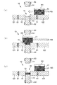
図1は、本発明の成形装置の第1実施形態の型閉め状態を示す縦断面図、図2は、本発明の成形装置の第1実施形態の型開き状態を示す縦断面図、図3は、本発明の成形体の製造方法により製造された成形体を模式的に示す縦断面図、図4〜6は、第1実施形態にかかる成形体の製造方法を説明するための図(縦断面図)である。なお、以下の説明では、図1〜6中の上側を「上」、下側を「下」と言う。
図1に示す成形装置1は、キャビティに粉末を充填することにより、キャビティの形状をなす加圧成形体を製造する装置である。
FIG. 1 is a longitudinal sectional view showing a mold closing state of the first embodiment of the molding apparatus of the present invention. FIG. 2 is a longitudinal sectional view showing a mold opening state of the first embodiment of the molding apparatus of the present invention. BRIEF DESCRIPTION OF THE DRAWINGS These are the longitudinal cross-sectional views which show typically the molded object manufactured by the manufacturing method of the molded object of this invention, FIGS. 4-6 is a figure (longitudinal section) for demonstrating the manufacturing method of the molded object concerning 1st Embodiment. Is a plan view). In the following description, the upper side in FIGS. 1 to 6 is referred to as “upper” and the lower side is referred to as “lower”.
A
以下、成形装置1の各部について詳細に説明する。
図1に示す成形装置1は、フレーム2と、フレーム2の下部に固定され、後述する下パンチを固定するパンチ固定テーブル3と、フレーム2の上部に固定されたプレート4と、粉末を成形する成形型10とを有する。
成形型10は、上下に貫通した貫通孔11を備えた板状のダイ12と、ダイ12の下方に設けられた棒状の下パンチ13と、ダイ12の上方に設けられた棒状の上パンチ14とを有している。これらのダイ12、下パンチ13および上パンチ14で囲まれた空間が、キャビティ15となる。
Hereinafter, each part of the shaping |
A
The molding die 10 includes a plate-like die 12 having a through-hole 11 penetrating vertically, a rod-like
図1に示すキャビティ15は、直方体形状をなしている。そして、このキャビティ15は、その側面がダイ12の一部によって構成され、その下面が下パンチ13の一部によって構成され、その上面が上パンチ14の一部によって構成されている。
ダイ12は、ダイ12と同一面に設けられた板状のダイセット121、122に支持されている。
The
The die 12 is supported by plate-like die
また、このダイセット121、122は、その下面が、それぞれ、各ガイドポスト123、123を介して、ダイ12の下方に設けられたダイセット連結板124の上面に接続されている。また、このダイセット連結板124は、その下面が、シリンダロッド125を介して、フレーム2の下面に設けられた下部油圧シリンダ126に接続されている。
このような構成により、ダイセット121、122は、シリンダロッド125、ダイセット連結板124および各ガイドポスト123、123を介して、下部油圧シリンダ126により上下に移動可能である。
The lower surfaces of the
With this configuration, the die sets 121 and 122 can be moved up and down by the lower
また、ダイセット121、122の上面には、それぞれ、各ガイドポスト127、127が設けられている。
なお、シリンダロッド125は、パンチ固定テーブル3が備える貫通孔31に挿通されている。
下パンチ13は、ベースプレート131上に設けられている。
Further, guide posts 127 and 127 are provided on the upper surfaces of the die sets 121 and 122, respectively.
The
The
また、このベースプレート131は、その下面が、2本の支柱132、132を介して、ベースプレート131の下方に設けられた前述のパンチ固定テーブル3の上面に接続されている。これにより、下パンチ13は、フレーム2に固定されている。
また、ベースプレート131は、2つの貫通孔133、133を有しており、これらの貫通孔133、133に、2本のガイドポスト123、123が挿通されている。このような構成により、各ガイドポスト123、123は、各貫通孔133、133にガイドされつつ、上下に移動することができる。
In addition, the lower surface of the
The
上パンチ14は、上パンチプレート141の下面に設けられている。
また、この上パンチプレート141は、その上面が、シリンダロッド142を介して、プレート4の上面に設けられた上部油圧シリンダ143に接続されている。
このような構成により、上パンチ14は、上パンチプレート141およびシリンダロッド142を介して、上部油圧シリンダ143により上下に移動可能である。
また、上パンチプレート141は、2つの貫通孔144、144を有している。これらの貫通孔144、144に、2本のガイドポスト127、127が挿通されている。このような構成により、各ガイドポスト127、127は、各貫通孔144、144にガイドされつつ、上下に移動することができる。
The
Further, the upper surface of the
With such a configuration, the
The
なお、シリンダロッド142は、プレート4が備える貫通孔41に挿通されている。
このような成形装置1では、下パンチ13および上パンチ14が、それぞれ、ダイ12に対して相対的に移動可能となっている。また、下パンチ13および上パンチ14は、それぞれ、貫通孔11に対して挿抜可能に設けられている。これにより、ダイ12、下パンチ13および上パンチ14で画成されるキャビティ15の体積は、下パンチ13および上パンチ14の移動に応じて変化し、体積が最小となる図1に示す型閉め状態と、キャビティ15が開放される図2に示す型開き状態とをとり得る。
The
In such a
また、ダイセット122上には、粉末供給部(粉末供給手段)16が設けられている。
この粉末供給部16は、キャビティ15に供給する粉末5を収納する箱状のフィーダボックス161と、油圧シリンダ162と、フィーダボックス161と油圧シリンダ162とを接続するシリンダロッド163とを有している。このような構成により、フィーダボックス161は、油圧シリンダ162により、シリンダロッド163を介して、ダイセット122の上面を左右に移動可能である。
A powder supply unit (powder supply means) 16 is provided on the die set 122.
The
ここで、箱状のフィーダボックス161の下面は、開放された状態になっている。このため、粉末5を収納した状態で、フィーダボックス161を図1の左側に移動させ、図2に示すように、フィーダボックス161をキャビティ15の上方まで移動させると、フィーダボックス161の下面から粉末5が落下し、キャビティ15に供給される。
ところで、成形装置1は、図1に示すように、キャビティ15の周辺に複数のコイル61、62、63を備えている。
Here, the lower surface of the box-shaped
By the way, as shown in FIG. 1, the
具体的には、ダイ12を囲うように、各ダイセット121、122のそれぞれダイ12側の境界部付近に、コイル61が埋め込まれている。これにより、キャビティ15がコイル61に囲まれている。また、コイル61には、図示しない電源回路が接続されており、この電源回路によって、コイル61に電圧が印加される。そして、コイル61に電圧が印加されると、ダイ12およびキャビティ15に確実に磁界が発生する。
Specifically, the
また、下パンチ13を囲うように、下パンチ13の上部にコイル62が設けられている。このコイル62にも、図示しない電源回路が接続されており、この電源回路によって、コイル62に電圧が印加される。そして、コイル62に電圧が印加されることにより、下パンチ13や、下パンチ13の上方に位置するキャビティ15に、それぞれ確実に磁界が発生する。
A
また、上パンチ14を囲うように、上パンチ14の下部にコイル63が設けられている。このコイル63にも、図示しない電源回路が接続されており、この電源回路によって、コイル63に電圧が印加される。そして、コイル63に電圧が印加されることにより、上パンチ14や、上パンチ14の下方に位置するキャビティ15に、それぞれ確実に磁界が発生する。
A
すなわち、キャビティ15の周辺に設けられた複数のコイル61、62、63と、各コイルに接続された電源回路とにより、キャビティ15に磁界を付与する磁界付与手段を構成している。
なお、この磁界付与手段は、キャビティ15に磁界を付与するものであればよく、例えば、キャビティ15の周辺において着脱自在の永久磁石等で代替することもできる。
That is, a plurality of
The magnetic field applying means may be any means as long as it applies a magnetic field to the
また、ダイ12、下パンチ13および上パンチ14は、それぞれ金属材料で構成されているが、軟磁性材料で構成されているのが好ましい。これにより、各コイル61、62、63が通電状態にあるときには、ダイ12、下パンチ13および上パンチ14に磁界を発生させることができ、各コイル61、62、63が非通電状態にあるときには、磁界の発生を止めることができる。すなわち、磁界の発生を任意に制御することができる。
なお、ダイ12、下パンチ13および上パンチ14が硬磁性材料で構成されている場合には、各コイル61、62、63の通電によって、ダイ12、下パンチ13および上パンチ14が磁化してしまい、各コイル61、62、63を非通電状態にしても、磁界の発生が継続されてしまうおそれがある。
The
When the die 12, the
以上のような成形装置1を用いることにより、図3に示すように、本体部72と、この本体部72の表面を覆うように形成された被覆層71とを有する複合成形体7を製造することができる。
このような複合成形体7のうち、被覆層71は、第1の粉末の成形体で構成されており、一方、本体部72は、第1の粉末と種類の異なる第2の粉末の成形体で構成されている。
By using the
In such a composite molded body 7, the covering
かかる複合成形体7では、第1の粉末の組成と第2の粉末の組成を適宜設定することにより、本体部72および被覆層71の各特性(機械的特性、化学的特性および電磁気的特性)を異ならせることができる。このため、かかる複合成形体7は、機能性に優れたものとなる。
このようにして得られた複合成形体7は、バインダを硬化させる工程を経ることにより、圧粉成形体となる。
In the composite molded body 7, the characteristics of the
The composite molded body 7 thus obtained becomes a powder molded body through a step of curing the binder.
一方、得られた複合成形体7を、脱脂・焼成することにより、複合成形体7中からバインダを分解・除去するとともに、第1の粉末および第2の粉末を焼結させ、焼結体を得ることができる。
次に、本発明の成形体の製造方法について、前述の成形装置1を用いて行う場合を例に説明する。
On the other hand, the resulting composite molded body 7 is degreased and fired to decompose and remove the binder from the composite molded body 7 and to sinter the first powder and the second powder. Obtainable.
Next, the manufacturing method of the molded body of the present invention will be described by taking as an example a case where the
本実施形態にかかる成形体の製造方法は、成形型10のキャビティ15内に、磁性材料で構成された第1の粉末とバインダとを含む第1の組成物を供給するとともに、キャビティ15内に磁界を付与することにより、第1の組成物をキャビティ15の内壁面に吸着させる第1の工程と、内壁面に第1の組成物を吸着させたキャビティ15内に、第1の粉末と種類の異なる第2の粉末とバインダとを含む第2の組成物を供給する第2の工程と、キャビティ15内に供給された第1の組成物と第2の組成物とを加圧成形する第3の工程とを有する。
かかる成形体の製造方法によれば、前述した複合成形体7を容易に効率よく製造することができる。
In the method for producing a molded body according to the present embodiment, a first composition containing a first powder made of a magnetic material and a binder is supplied into the
According to this method of manufacturing a molded body, the above-described composite molded body 7 can be easily and efficiently manufactured.
以下、各工程について順次説明する。
[1]まず、バインダを溶媒に溶解して、バインダ溶液を調製する。
バインダとしては、例えば、ポリビニルアルコール(PVA)、ポリビニルピロリドン(PVP)、ステアリン酸亜鉛、ステアリン酸リチウム、ステアリン酸カルシウム、エチレンビスステアロアミド、エチレンビニル共重合体、パラフィン、ワックス、アルギン酸ソーダ、寒天、アラビアゴム、レジン、しょ糖等が挙げられ、これらのうちの1種または2種以上を組み合わせて用いることができる。
Hereinafter, each process will be described sequentially.
[1] First, a binder is dissolved in a solvent to prepare a binder solution.
Examples of the binder include polyvinyl alcohol (PVA), polyvinyl pyrrolidone (PVP), zinc stearate, lithium stearate, calcium stearate, ethylene bisstearamide, ethylene vinyl copolymer, paraffin, wax, sodium alginate, agar, Examples include gum arabic, resin, and sucrose, and one or more of these can be used in combination.
この中でも、ポリビニルアルコールまたはポリビニルピロリドンが好ましい。このようなバインダは、低価格で入手が容易であるにもかかわらず、結合力が強い。また、加熱によって容易に熱分解するため、意図しない成分が残留し難い、すなわち脱バインダ特性が高いという利点もある。
一方、バインダを溶解する溶媒としては、バインダを溶解し得るものであれば特に限定されないが、例えば、水、二硫化炭素、四塩化炭素等の無機溶媒や、ケトン系溶媒、アルコール系溶媒、エーテル系溶媒、セロソルブ系溶媒、脂肪族炭化水素系溶媒、芳香族炭化水素系溶媒、芳香族複素環化合物系溶媒、アミド系溶媒、ハロゲン化合物系溶媒、エステル系溶媒、アミン系溶媒、ニトリル系溶媒、ニトロ系溶媒、アルデヒド系溶媒等の有機溶媒等が挙げられ、これらから選択される1種または2種以上を混合したものを用いることができる。
Among these, polyvinyl alcohol or polyvinyl pyrrolidone is preferable. Such a binder has a strong bonding force despite being inexpensive and easily available. Moreover, since it decomposes easily by heating, there is an advantage that unintended components hardly remain, that is, the binder removal characteristic is high.
On the other hand, the solvent for dissolving the binder is not particularly limited as long as it can dissolve the binder. For example, inorganic solvents such as water, carbon disulfide, carbon tetrachloride, ketone solvents, alcohol solvents, ethers Solvent, cellosolve solvent, aliphatic hydrocarbon solvent, aromatic hydrocarbon solvent, aromatic heterocyclic compound solvent, amide solvent, halogen compound solvent, ester solvent, amine solvent, nitrile solvent, Examples thereof include organic solvents such as nitro solvents and aldehyde solvents, and one or a mixture of two or more selected from these can be used.
次いで、第1の粉末とバインダ溶液とを用いて、第1の粉末の造粒粉末を得る。なお、以下では、この第1の粉末の造粒粉末を「第1の造粒粉末」と言う。
次いで、第2の粉末とバインダ溶液とを用いて、第2の粉末の造粒粉末を得る。なお、以下では、この第2の粉末の造粒粉末を「第2の造粒粉末」と言う。
ここで、第1の粉末は、磁性材料で構成されたものである。
この磁性材料としては、例えば、Fe系金属、Co系金属、Ni系金属のような磁性金属材料、フェライトのような磁性セラミックス材料等が挙げられる。
Next, a granulated powder of the first powder is obtained using the first powder and the binder solution. Hereinafter, the granulated powder of the first powder is referred to as “first granulated powder”.
Next, a granulated powder of the second powder is obtained using the second powder and the binder solution. Hereinafter, the granulated powder of the second powder is referred to as “second granulated powder”.
Here, the first powder is made of a magnetic material.
Examples of the magnetic material include magnetic metal materials such as Fe-based metals, Co-based metals, and Ni-based metals, and magnetic ceramic materials such as ferrite.
一方、第2の粉末の各構成材料としては、特に限定されないが、例えば、Fe、Ni、Co、Cr、Mn、Zn、Pt、Au、Ag、Cu、Pd、Al、W、Ti、V、Mo、Nb、Zr、Pr、Nd、Smのような金属材料またはこれらの金属元素を含む合金、アルミナ、マグネシア、ベリリア、ジルコニア、イットリア、フォルステライト、ステアタイト、ワラステナイト、ムライト、コージライト、フェライト、サイアロン、酸化セリウムのような酸化物系セラミックス材料、窒化ケイ素、窒化アルミニウム、窒化ホウ素、窒化チタン、炭化ケイ素、炭化ホウ素、炭化チタン、炭化タングステンのような非酸化物系セラミックス材料、グラファイト、ナノカーボン(カーボンナノチューブ、フラーレン等)の炭素系材料等が挙げられ、これらのうちの1種または2種以上を組み合わせて用いることができる。 On the other hand, each constituent material of the second powder is not particularly limited. For example, Fe, Ni, Co, Cr, Mn, Zn, Pt, Au, Ag, Cu, Pd, Al, W, Ti, V, Metal materials such as Mo, Nb, Zr, Pr, Nd, Sm or alloys containing these metal elements, alumina, magnesia, beryllia, zirconia, yttria, forsterite, steatite, wollastonite, mullite, cordierite, ferrite , Oxide ceramic materials such as sialon, cerium oxide, non-oxide ceramic materials such as silicon nitride, aluminum nitride, boron nitride, titanium nitride, silicon carbide, boron carbide, titanium carbide, tungsten carbide, graphite, nano Carbon-based materials such as carbon (carbon nanotube, fullerene, etc.) It can be used singly or in combination of two or more of these.
なお、第1の粉末および第2の粉末の造粒は、例えば、転動流動造粒法、転動造粒法、噴霧乾燥法(スプレードライヤー)、撹拌混合造粒、押出造粒、破砕造粒、圧縮造粒等の各種造粒方法により行うことができる。
また、溶媒に溶解させるバインダの重量は、第1の粉末または第2の粉末の重量1kg当たり、それぞれ0.5〜30g程度であるのが好ましく、1〜20g程度であるのがより好ましい。バインダの重量が前記範囲内になるように設定されることにより、第1の粉末または第2の粉末の表面を十分な量のバインダで被覆するとともに、被覆に寄与しないバインダが多量に発生するのを防止することができる。その結果、後述する工程において、保形性および成形密度に優れた成形体を作製可能な造粒粉末が得られる。
The granulation of the first powder and the second powder is, for example, rolling fluid granulation method, rolling granulation method, spray drying method (spray dryer), stirring and mixing granulation, extrusion granulation, crush granulation It can be performed by various granulation methods such as granulation and compression granulation.
Further, the weight of the binder dissolved in the solvent is preferably about 0.5 to 30 g, more preferably about 1 to 20 g, per 1 kg of the weight of the first powder or the second powder. By setting the weight of the binder to be within the above range, the surface of the first powder or the second powder is coated with a sufficient amount of binder, and a large amount of binder that does not contribute to coating is generated. Can be prevented. As a result, a granulated powder capable of producing a molded body excellent in shape retention and molding density is obtained in the steps described later.
また、バインダの溶解に用いる溶媒の重量は、バインダ1g当たり5〜100g程度であるのが好ましく、7〜70g程度であるのがより好ましい。溶媒の重量を前記範囲内に設定することにより、バインダを確実に溶解するとともに、溶媒の量が多くなり過ぎて、バインダ溶液の粘性が著しく低下し、後述する工程において作製する成形体の保形性が低下するのを確実に防止することができる。 Further, the weight of the solvent used for dissolving the binder is preferably about 5 to 100 g, and more preferably about 7 to 70 g, per 1 g of the binder. By setting the weight of the solvent within the above range, the binder is surely dissolved, the amount of the solvent is excessively increased, the viscosity of the binder solution is remarkably lowered, and the shape retention of the molded body produced in the process described later It is possible to reliably prevent the performance from deteriorating.
このようにして得られた第1の造粒粉末および第2の造粒粉末の平均粒径は、それぞれ40〜180μm程度であるのが好ましく、45〜140μm程度であるのがより好ましく、50〜100μm程度であるのがさらに好ましい。各造粒粉末の平均粒径を前記範囲内に設定することにより、それぞれの造粒粉末を成形型に充填して成形体を形成する際に、各造粒粉末が、流動性および成形型への充填性に優れたものとなる。 The average particle size of the first granulated powder and the second granulated powder thus obtained is preferably about 40 to 180 μm, more preferably about 45 to 140 μm, and more preferably 50 to More preferably, it is about 100 μm. By setting the average particle size of each granulated powder within the above range, when each granulated powder is filled into a mold and a molded body is formed, each granulated powder is converted into fluidity and mold. It is excellent in filling property.
なお、平均粒径が前記下限値を下回ると、各造粒粉末の流動性が安定せず、成形体の寸法バラツキが大きくなる可能性がある。一方、平均粒径が前記上限値を上回ると、特に小さい成形体を形成する際に、各造粒粉末の充填ムラが起こり易くなり、成形体の寸法バラツキが大きくなる可能性がある。
以上は、第1の粉末と第2の粉末として微細で流動性の悪い粉末を用いた際に、流動性と保形性を改善するために造粒する場合について述べたが、もともと流動性・保形性の高い粉末、例えば平均粒径40μm以上の水アトマイズ粉末を第1、第2の粉末として用いる場合には、造粒工程を省いても良い。
In addition, when an average particle diameter is less than the said lower limit, the fluidity | liquidity of each granulated powder will not be stabilized and the size variation of a molded object may become large. On the other hand, when the average particle size exceeds the upper limit, when forming a particularly small compact, uneven filling of each granulated powder is likely to occur, and the dimensional variation of the compact may increase.
The above describes the case where granulation is performed to improve fluidity and shape retention when fine and poorly flowable powder is used as the first powder and the second powder. In the case where powder having high shape retention, for example, water atomized powder having an average particle size of 40 μm or more is used as the first and second powders, the granulation step may be omitted.
[2]次に、図4(a)に示すように、成形型10を型開き状態とする。そして、フィーダボックス161に第1の造粒粉末51を収納する。
次いで、このフィーダボックス161を、キャビティ15の上方に至るまで左側に移動させる。これにより、図4(b)に示すように、フィーダボックス161内の第1の造粒粉末51が、キャビティ15に供給される。
[2] Next, as shown in FIG. 4A, the
Next, the
このとき、キャビティ15に供給される第1の造粒粉末51の量(体積)を適宜設定することにより、最終的に得られる複合成形体7における被覆層71の厚さを調整することができる。
なお、キャビティ15に供給される第1の造粒粉末51の量は、ダイ12を上下方向に移動させ、キャビティ15の体積を変化させることにより適宜設定することができる。
At this time, by appropriately setting the amount (volume) of the first
The amount of the first
[3]次に、図4(c)に示すように、フィーダボックス161を元の位置に戻すとともに、ダイ12を上方向に移動させ、キャビティ15の体積を拡大する。
このときのキャビティ15の体積は、後述する工程において、第1の造粒粉末51と第2の造粒粉末52とを圧縮する際の圧縮率を考慮して決定される。
また、上パンチ14の下面位置がダイ12の上面位置になるまで下降させる。
[3] Next, as shown in FIG. 4C, the
The volume of the
Further, the
[4]次に、各電源回路610、620、630により、各コイル61、62、63に、それぞれ電圧を印加する。これにより、ダイ12、下パンチ13および上パンチ14に、それぞれ磁界が発生する。この磁界は、キャビティ15に付与される。
この磁界による第1の軟磁性粉末の着磁作用により、キャビティ15内に供給された第1の造粒粉末51は、図5(d)に示すように、キャビティ15の側面および下面に吸着される。
[4] Next, each
Due to the magnetizing action of the first soft magnetic powder by this magnetic field, the first
また、第1の造粒粉末51の一部は、上パンチ14による磁界によって上方に飛び出し、上パンチ14の下面に吸着(配置)される(第1の工程)。このように、磁界による第1の軟磁性粉末の着磁作用を用いることにより、第1の造粒粉末51をキャビティ15の内壁面に簡単に配置することができる。
なお、前記工程[1]において、あらかじめ第1の粉末とバインダとにより第1の造粒粉末51を製造し、前記工程[2]において、この第1の造粒粉末51をキャビティ15に供給するようにしたので、第1の粉末とバインダとが均一に分散した状態で、キャビティ15に供給されることとなる。
Further, a part of the first
In the step [1], the first
また、このように、第1の造粒粉末51をキャビティ15に供給することにより、磁性材料でないバインダも、第1の粉末とともにキャビティ15の内壁面に吸着させることができる。これにより、得られる成形体の表面付近の保形性を高めることができる。
ここで、本実施形態では、キャビティ15の周辺に設けられた複数のコイル61、62、63と、各コイルに接続された各電源回路610、620、630とにより、キャビティ15に磁界を付与する磁界付与手段を構成している。このような構成の磁界付与手段によれば、電源回路を操作することによって、磁界の付与を容易かつ正確に制御することができる。
また、各コイル61、62、63に印加する電圧をそれぞれ異ならせることにより、キャビティ15の内壁面のうち、側面、下面および上面の間で、発生する磁界の強さを異ならせることができる。これにより、キャビティ15の側面、下面および上面に吸着する第1の造粒粉末51の量を、それぞれ異ならせることができる。
Further, by supplying the first
Here, in the present embodiment, a magnetic field is applied to the
Further, by changing the voltages applied to the
[5]次に、図5(e)に示すように、フィーダボックス161内の第1の造粒粉末51を取り出し、第2の造粒粉末52に入れ替える。
[6]次に、図5(f)に示すように、各コイル61、62、63に電圧を印加した状態で、フィーダボックス161を、キャビティ15の上方に至るまで左側に移動させる。これにより、図5(f)に示すように、フィーダボックス161内の第2の造粒粉末52が、キャビティ15に供給され、充填される(第2の工程)。
[5] Next, as shown in FIG. 5 (e), the first
[6] Next, as shown in FIG. 5 (f), the
[7]次に、コイル63に電圧を印加した状態で、図6(g)に示すように、フィーダボックス161を元の位置に戻す。
次いで、図6(h)に示すように、上パンチ14を下方に移動させ、キャビティ15に挿入し、成形型10を型閉め状態とする。これにより、キャビティ15内の第1の造粒粉末51と第2の造粒粉末52とを同時に加圧して成形する(第3の工程)。その結果、キャビティ15内に複合成形体7が得られる。
[7] Next, with the voltage applied to the
Next, as shown in FIG. 6 (h), the
[8]次に、図6(i)に示すように、上パンチ14を上方に移動させ、型開き状態とする。
また、ダイ12を下方に移動させ、キャビティ15内の複合成形体7を、下パンチ13によって押し上げる。これにより、キャビティ15内から複合成形体7を取り出すことができる。
[8] Next, as shown in FIG. 6 (i), the
Further, the
以上のようにして、複合成形体7を製造することができる。
なお、本発明では、第1の造粒粉末51と第2の造粒粉末52とを同時に加圧・成形するので、第2の造粒粉末52の加圧成形体で構成された本体部72と、第1の造粒粉末51の加圧成形体で構成された被覆層71との密着性が高くなる。このため、複合成形体7において、本体部72から被覆層71が剥離するのを確実に防止することができる。
The composite molded body 7 can be manufactured as described above.
In the present invention, the first
ここで、複合成形体7の製造に用いられる第1の粉末および第2の粉末は、その構成成分として、共通の金属元素を含んでいるのが好ましい。これにより、図3に示す本体部72と被覆層71との間の密着性をより高めることができる。
また、第1の粉末として、第2の粉末よりも耐食性に優れたものを用いるのが好ましい。これにより、外表面の耐食性が高い複合成形体7が得られる。また、例えば、第2の粉末として、磁気特性に優れたものを用いることにより、耐食性が高く、かつ、磁気特性に優れた複合成形体7が得られる。
Here, it is preferable that the 1st powder and 2nd powder used for manufacture of the composite molded object 7 contain the common metal element as the structural component. Thereby, the adhesiveness between the main-
In addition, it is preferable to use a powder that has better corrosion resistance than the second powder as the first powder. Thereby, the composite molded object 7 with high corrosion resistance of an outer surface is obtained. Further, for example, by using a powder having excellent magnetic properties as the second powder, a composite molded body 7 having high corrosion resistance and excellent magnetic properties can be obtained.
なお、第2の粉末として、例えば磁気特性等の各特性が高いにもかかわらず、耐食性に劣るような粉末をも用いることができる。これにより、第2の粉末の選択の幅を広げることができる。
かかる観点から、第1の粉末を構成する磁性材料は、その構成成分としてAl、Si、CrおよびTiのうちの少なくとも1種を含んでいるのが好ましい。これらの元素は、大気中の酸素と結合して、化学的に安定な酸化物を生成する。このため、特に高い耐食性を有する複合成形体7が得られる。
As the second powder, it is also possible to use a powder that is inferior in corrosion resistance despite having high characteristics such as magnetic characteristics. Thereby, the selection range of the 2nd powder can be expanded.
From this viewpoint, it is preferable that the magnetic material constituting the first powder contains at least one of Al, Si, Cr, and Ti as its constituent components. These elements combine with atmospheric oxygen to produce chemically stable oxides. For this reason, the composite molded object 7 which has especially high corrosion resistance is obtained.
また、第1の粉末は、その焼結温度が、第2の粉末の焼結温度よりも高いものが好ましい。これにより、複合成形体7を徐々に加熱して脱脂・焼成し、焼結体を得る際に、複合成形体7の本体部72が被覆層71よりも先に焼結することとなる。その結果、被覆層71が本体部72よりも先に焼結するのを防止し、複合成形体7の内部に、バインダやその分解物が閉じ込められるのを確実に防止することができる。
The first powder preferably has a sintering temperature higher than that of the second powder. Thereby, when the composite molded body 7 is gradually heated and degreased and fired to obtain a sintered body, the
また、第1の粉末は、その平均粒径が、第2の粉末の平均粒径よりも大きいものが好ましい。これにより、複合成形体7を徐々に加熱して脱脂・焼成する際に、被覆層71において、第1の粉末の粒子間に隙間が生じ易い。このため、本体部72が含むバインダの分解物が、被覆層71に生じた粒子間の隙間を介して、複合成形体7の外部に容易に放出される。その結果、複合成形体7の脱脂をより確実に行うことができ、焼結体の炭素含有率が、第1の粉末および第2の粉末の各炭素含有率に比べて著しく増加するのを防止することができる。
The first powder preferably has an average particle size larger than the average particle size of the second powder. Thereby, when the composite molded body 7 is gradually heated and degreased and fired, a gap is likely to be generated between the particles of the first powder in the
なお、複合成形体7の脱脂・焼成については、後に詳述する。
また、本実施形態では、キャビティ15内に磁界を付与することにより、第1の組成物をキャビティ15の内壁面に吸着させるよう構成されているが、その他の方法により、吸着させるようにしてもよい。
具体的には、静電吸着の作用により第1の組成物を吸着させる方法、キャビティ15の内壁面にあらかじめ粘着剤を塗布しておき、その粘着作用により第1の組成物を吸着させる方法等が挙げられる。
なお、これらの方法を用いる場合には、第1の粉末が必ずしも磁性材料で構成されていなくてもよく、前記第2の粉末と同様の材料で構成されたものを用いることができる。
The degreasing and firing of the composite molded body 7 will be described in detail later.
In the present embodiment, the first composition is adsorbed on the inner wall surface of the
Specifically, a method of adsorbing the first composition by the action of electrostatic adsorption, a method of applying an adhesive to the inner wall surface of the
When these methods are used, the first powder does not necessarily need to be made of a magnetic material, and a powder made of the same material as the second powder can be used.
次に、前記工程[8]によって得られた複合成形体7に対して、以下の工程[9A]〜[10A]を行うことにより、焼結体を得ることができる。
[9A]まず、得られた複合成形体7に脱脂処理(脱バインダ処理)を施す。これにより、脱脂体を得る。
この脱脂処理は、特に限定されないが、非酸化性雰囲気中、例えば真空または減圧状態下(例えば1×10⁻¹〜1×10⁻⁶Torr(13.3〜1.33×10⁻⁴Pa))、または、窒素ガス、アルゴンガス、水素ガス、アンモニア分解ガス等のガス中で、熱処理を行うことによりなされる。
Next, a sintered body can be obtained by performing the following steps [9A] to [10A] on the composite molded body 7 obtained by the step [8].
[9A] First, the obtained composite molded body 7 is degreased (binder removal). Thereby, a degreased body is obtained.
The degreasing treatment is not particularly limited, but in a non-oxidizing atmosphere, for example, in a vacuum or under reduced pressure (for example, 1 × 10 −1 to 1 × 10 −6 Torr (13.3 to 1.33 × 10 −4 Pa) ), Or by performing a heat treatment in a gas such as nitrogen gas, argon gas, hydrogen gas, or ammonia decomposition gas.
この場合、熱処理の条件は、バインダの分解開始温度等によって若干異なるが、好ましくは温度100〜750℃程度で0.5〜20時間程度、より好ましくは温度150〜700℃程度で1〜10時間程度とされる。
また、このような熱処理による脱脂は、種々の目的(例えば、脱脂時間の短縮等の目的)で、複数の工程(段階)に分けて行ってもよい。この場合、例えば、前半を低温で、後半を高温で脱脂するような方法や、低温と高温を繰り返し行う方法等が挙げられる。
なお、バインダは、脱脂処理によって複合成形体7から完全に除去されなくてもよく、例えば、脱脂処理の完了時点で、その一部が残存していてもよい。
In this case, the heat treatment conditions vary slightly depending on the decomposition start temperature of the binder, etc., but are preferably about 100 to 750 ° C. for about 0.5 to 20 hours, more preferably about 150 to 700 ° C. for 1 to 10 hours. It is said to be about.
Further, degreasing by such heat treatment may be performed in a plurality of steps (stages) for various purposes (for example, for shortening the degreasing time). In this case, for example, a method in which the first half is degreased at a low temperature and the second half at a high temperature, a method in which low temperature and high temperature are repeated, and the like can be mentioned.
The binder may not be completely removed from the composite molded body 7 by the degreasing process. For example, a part of the binder may remain when the degreasing process is completed.
[10A]次に、得られた脱脂体を焼成する。この焼成により、脱脂体が焼結し、焼結体となる。
焼成温度は、第1の粉末および第2の粉末の各組成や粒径等によって異なるため、特に限定されないが、例えば、第1の粉末および第2の粉末がいずれもFe系合金で構成されている場合、1100〜1400℃程度であるのが好ましく、1150〜1350℃程度であるのがより好ましい。
[10A] Next, the obtained degreased body is fired. By this firing, the degreased body is sintered and becomes a sintered body.
The firing temperature is not particularly limited because it varies depending on the composition and particle size of the first powder and the second powder. For example, both the first powder and the second powder are made of an Fe-based alloy. When it is, it is preferable that it is about 1100-1400 degreeC, and it is more preferable that it is about 1150-1350 degreeC.
また、焼成時間は、焼成温度によって異なるものの、0.5〜20時間程度であるのが好ましく、1〜15時間程度であるのがより好ましい。
また、焼成雰囲気は、減圧(真空)下または非酸化性雰囲気とするのが好ましい。これにより、第1の粉末や第2の粉末の酸化による特性劣化を防止することができる。
このうち、具体的な減圧(真空)下の焼成雰囲気としては、1Torr(133Pa)以下の減圧(真空)下であるのが好ましく、1×10⁻⁶〜1×10⁻²Torr(1.33×10⁻⁴〜1.33Pa)の減圧(真空)下であるのがより好ましい。
Moreover, although baking time changes with baking temperature, it is preferable that it is about 0.5 to 20 hours, and it is more preferable that it is about 1 to 15 hours.
The firing atmosphere is preferably a reduced pressure (vacuum) or non-oxidizing atmosphere. Thereby, characteristic deterioration due to oxidation of the first powder and the second powder can be prevented.
Among these, a specific firing atmosphere under reduced pressure (vacuum) is preferably under reduced pressure (vacuum) of 1 Torr (133 Pa) or less, preferably 1 × 10 −6 to 1 × 10 −2 Torr (1.33). It is more preferable to be under reduced pressure (vacuum) of × 10 −4 to 1.33 Pa).
また、具体的な非酸化性雰囲気としては、窒素ガス、アルゴンガス等の不活性ガス雰囲気、水素ガス等の還元性ガス雰囲気であるのが好ましい。
ここで、第1の粉末の焼結温度TS1が、第2の粉末の焼結温度TS2よりも高い場合、焼成条件を以下のように設定するのが好ましい。
すなわち、この焼成条件は、脱脂体(成形体)を、焼結温度TS2以上かつ焼結温度TS1未満の温度で加熱して、脱脂体(成形体)の内側にある第2の粉末を選択的に焼結させた後、焼結温度TS1以上の温度で加熱して、脱脂体の外側にある第1の粉末を焼結させるような条件である。
Further, specific non-oxidizing atmospheres are preferably an inert gas atmosphere such as nitrogen gas and argon gas, and a reducing gas atmosphere such as hydrogen gas.
Here, when the sintering temperature T S1 of the first powder is higher than the sintering temperature T S2 of the second powder, it is preferable to set the firing conditions as follows.
That is, the firing condition is that the degreased body (molded body) is heated at a temperature equal to or higher than the sintering temperature T S2 and lower than the sintering temperature T S1, and the second powder inside the degreased body (shaped body) is heated. After selective sintering, the first powder on the outside of the degreased body is sintered by heating at a temperature equal to or higher than the sintering temperature T S1 .
このような条件で焼成することにより、脱脂体(成形体)の内側から外側に向かって焼結を進行させることができる。これにより、脱脂体(成形体)中に残存していたバインダやその分解物が、焼結に伴って、内側から徐々に放出されることとなり、最終的に得られる焼結体中に残存することが確実に防止される。その結果、焼結体の炭素含有率が、第1の粉末および第2の粉末の各炭素含有率に比べて著しく増加するのを確実に防止することができる。 By firing under such conditions, sintering can proceed from the inside to the outside of the degreased body (molded body). As a result, the binder and decomposition products remaining in the degreased body (molded body) are gradually released from the inside along with the sintering, and remain in the finally obtained sintered body. Is reliably prevented. As a result, it is possible to reliably prevent the carbon content of the sintered body from significantly increasing as compared with the carbon contents of the first powder and the second powder.
なお、焼成工程を行う雰囲気は、工程の途中で変化してもよい。例えば、最初に減圧雰囲気とし、途中で不活性雰囲気に切り替えるようにしてもよい。
また、焼成工程は、2段階またはそれ以上に分けて行ってもよい。これにより、焼結の効率が向上し、より短い焼結時間で焼結を行うことができる。
また、焼成工程は、前述の脱脂工程と連続して行うのが好ましい。これにより、脱脂工程は、焼結前工程を兼ねることができ、脱脂体に予熱を与えて、脱脂体をより確実に焼結させることができる。
このようにして得られた焼結体は、第2の粉末が焼結してなる本体部と、この本体部の表面を覆うように強固に接合され、第1の粉末が焼結してなる被覆層とで構成された複合焼結体である。
Note that the atmosphere in which the firing process is performed may change during the process. For example, a reduced-pressure atmosphere may be set first, and an inert atmosphere may be switched on the way.
Moreover, you may perform a baking process in 2 steps or more. Thereby, the efficiency of sintering improves and it can sinter by shorter sintering time.
Moreover, it is preferable to perform a baking process continuously with the above-mentioned degreasing process. Thereby, a degreasing process can serve as a pre-sintering process, can preheat a degreased body, and can sinter a degreased body more certainly.
The sintered body thus obtained is firmly joined to the main body portion obtained by sintering the second powder so as to cover the surface of the main body portion, and the first powder is sintered. This is a composite sintered body composed of a coating layer.
かかる焼結体によれば、例えば、第1の粉末として、耐食性に優れた金属粉末を用い、第2の粉末として、機械的特性や電磁気的特性に優れた金属粉末を用いることにより、機械的特性や電磁気的特性に優れ、かつ耐食性にも優れた金属部品を容易に得ることができる。
なお、必要に応じて、前記工程[9A]〜[10A]に代えて、前記工程[8]で得られた複合成形体7に対し、以下の工程[9B]を行うようにしてもよい。
According to such a sintered body, for example, a metal powder having excellent corrosion resistance is used as the first powder, and a metal powder having excellent mechanical characteristics and electromagnetic characteristics is used as the second powder. It is possible to easily obtain a metal part having excellent characteristics and electromagnetic characteristics and excellent corrosion resistance.
If necessary, the following step [9B] may be performed on the composite molded body 7 obtained in the step [8] instead of the steps [9A] to [10A].
[9B]得られた複合成形体7を加熱することにより、バインダが固化し、圧粉成形体(加圧成形体)を得る。
本工程を行う場合、前述のバインダに代えて、熱硬化性のバインダを用いる。
熱硬化性のバインダとしては、例えば、シリコーン系樹脂、エポキシ系樹脂、フェノール系樹脂、ポリアミド系樹脂、ポリイミド系樹脂、ポリフェニレンサルファイド系樹脂等の有機バインダ、リン酸マグネシウム、リン酸カルシウム、リン酸亜鉛、リン酸マンガン、リン酸カドミウムのようなリン酸塩、ケイ酸ナトリウムのようなケイ酸塩(水ガラス)等の無機バインダ等が挙げられるが、特に、熱硬化性ポリイミドまたはエポキシ系樹脂が好ましい。これらの樹脂材料は、加熱されることによって容易に硬化するとともに、耐熱性に優れたものである。したがって、圧粉成形体の製造容易性および耐熱性を高めることができる。
[9B] By heating the obtained composite molded body 7, the binder is solidified to obtain a compacted body (pressed body).
When this step is performed, a thermosetting binder is used instead of the above-described binder.
Examples of the thermosetting binder include organic binders such as silicone resins, epoxy resins, phenol resins, polyamide resins, polyimide resins, polyphenylene sulfide resins, magnesium phosphate, calcium phosphate, zinc phosphate, phosphorus Examples thereof include inorganic binders such as phosphates such as manganese acid and cadmium phosphate, and silicates (water glass) such as sodium silicate, and thermosetting polyimide or epoxy resin is particularly preferable. These resin materials are easily cured by being heated and have excellent heat resistance. Therefore, it is possible to improve the ease of manufacturing and heat resistance of the green compact.
また、複合成形体7を加熱する際の加熱温度は、バインダの組成等に応じて若干異なるものの、例えばバインダが有機バインダで構成されている場合、好ましくは100〜250℃程度とされ、より好ましくは120〜200℃程度とされる。
また、加熱時間は、加熱温度に応じて異なるものの、0.5〜5時間程度とされる。
このようにして得られた圧粉成形体は、第2の粉末がバインダによって結着されてなる本体部72と、本体部72の表面を覆うように強固に固着して形成され、第1の粉末がバインダによって結着されてなる被覆層71とで構成された複合成形体となる。
Moreover, although the heating temperature at the time of heating the composite molded body 7 is slightly different depending on the composition of the binder, for example, when the binder is composed of an organic binder, it is preferably about 100 to 250 ° C., more preferably Is about 120-200 ° C.
Moreover, although heating time changes with heating temperature, it is set as about 0.5 to 5 hours.
The green compact thus obtained is formed by firmly adhering the
かかる圧粉成形体によれば、例えば、第1の粉末として、耐食性に優れた金属粉末を用い、第2の粉末として、磁気特性に優れた金属粉末を用いることにより、磁気特性に優れ、かつ耐食性にも優れた圧粉磁心を容易に得ることができる。
なお、前記工程[8]によって得られた複合成形体7は、本体部72と被覆層71の2層を有する複合成形体であるが、本発明の成形体の製造方法によれば、本体部、中間部分および被覆層の3層を有する複合成形体も同様に製造することができる。
例えば、本体部、中間部分および被覆層の3層を有する複合成形体を製造する場合、まず、前記工程[4]と同様にして、被覆層を構成する粉末として、磁性を有する第1の造粒粉末を用意し、これをキャビティの内壁面に吸着させる。
According to such a green compact, for example, a metal powder having excellent corrosion resistance is used as the first powder, and a metal powder having excellent magnetic properties is used as the second powder, so that the magnetic properties are excellent, and A dust core excellent in corrosion resistance can be easily obtained.
The composite molded body 7 obtained by the step [8] is a composite molded body having two layers of a
For example, when manufacturing a composite molded body having three layers of a main body portion, an intermediate portion, and a coating layer, first, in the same manner as in the step [4], the first structure having magnetism is used as the powder constituting the coating layer. A granular powder is prepared and adsorbed on the inner wall surface of the cavity.
次いで、前記工程[4]と同様にして、中間部分を構成する粉末として、磁性を有する第3の造粒粉末を用意し、これをキャビティの内壁面に吸着している第1の造粒粉末の内側に吸着させる。
次いで、前記工程[6]と同様にして、本体部を構成する粉末として、第2の造粒粉末を用意し、これをキャビティに供給し、充填する。
Next, in the same manner as in the above step [4], a third granulated powder having magnetism is prepared as a powder constituting the intermediate portion, and the first granulated powder adsorbing this on the inner wall surface of the cavity Adsorb inside.
Next, in the same manner as in the above step [6], a second granulated powder is prepared as a powder constituting the main body, and this is supplied to the cavity and filled.
以上のようにすれば、3層を有する複合成形体を製造することができる。また、4層以上の複合成形体も同様に製造することができる。
このように、本発明の成形体の製造方法により製造された圧粉成形体や、本発明の焼結体の製造方法により製造された焼結体は、各種部品等に適用可能であるが、例えば、チョークコイル、インダクタ、ノイズフィルタ、リアクトル、モータ、発電機のような各種磁性素子(電磁気部品)が備える磁心等に好適に適用される。
If it carries out as mentioned above, the composite molded object which has three layers can be manufactured. A composite molded body having four or more layers can also be produced in the same manner.
Thus, the green compact produced by the method for producing a molded article of the present invention and the sintered compact produced by the method for producing a sintered compact of the present invention can be applied to various parts, etc. For example, it is suitably applied to a magnetic core provided in various magnetic elements (electromagnetic components) such as a choke coil, an inductor, a noise filter, a reactor, a motor, and a generator.
以下、このような磁心を備える磁性素子の一例として、2種類のチョークコイルを代表に説明する。
まず、トロイダル形状のチョークコイルについて説明する。
図7は、トロイダル形状のチョークコイルを示す模式図(平面図)である。
図7に示すチョークコイル80は、リング状(トロイダル形状)の磁心81と、この磁心81に巻き回された導線82とを有する。このようなチョークコイル80は、一般に、トロイダルコイルと称される。
Hereinafter, two types of choke coils will be described as representative examples of magnetic elements having such a magnetic core.
First, a toroidal choke coil will be described.
FIG. 7 is a schematic diagram (plan view) showing a toroidal-shaped choke coil.
A
磁心81は、前述した成形体の製造方法により製造された圧粉成形体や、前述した焼結体の製造方法により製造された焼結体により構成される。
このような磁心81は、被覆層と本体部とでそれぞれの構成材料を適宜設定することにより、被覆層と本体部とでそれぞれの特性(機械的特性、化学的特性および電磁気的特性)を異ならせることができる。これにより、かかる磁心81は、機能性に優れたものとなる。
したがって、例えば、被覆層を、本体部よりも耐食性の高い材料で構成し、本体部を透磁率の高い材料で構成することにより、透磁率が高く、かつ耐食性の高い磁心81が得られる。
The
Such a
Therefore, for example, the
一方、導線82の構成材料としては、導電性の高い材料が挙げられ、例えば、Cu、Al、Ag、Au、Ni等の金属材料、またはかかる金属材料を含む合金等が挙げられる。
なお、導線82の表面に、絶縁性を有する表面層を備えているのが好ましい。これにより、圧粉磁心81と導線82との短絡を確実に防止することができる。
かかる表面層の構成材料としては、例えば、各種樹脂材料等が挙げられる。
On the other hand, examples of the constituent material of the
In addition, it is preferable to provide the surface of the
Examples of the constituent material of the surface layer include various resin materials.
次に、磁心中にコイルをモールドしたチョークコイルについて説明する。
図8は、磁心中にコイルをモールドしたチョークコイルを示す模式図(斜視図)である。
図8に示すチョークコイル90は、コイル状に成形された導線92を、磁心91の内部に埋設してなるものである。すなわち、チョークコイル90は、導線92を磁心91でモールドしてなる。
Next, a choke coil in which a coil is molded in a magnetic core will be described.
FIG. 8 is a schematic view (perspective view) showing a choke coil in which a coil is molded in a magnetic core.
A
このような形態のチョークコイル90は、比較的小型のものが容易に得られる。
また、導線92が磁心91の内部に埋設されているため、導線92と磁心91との間に隙間が生じ難い。このため、磁心91の磁歪による振動を抑制し、この振動に伴う騒音の発生を抑制することもできる。
なお、導線92は、前述の導線82と同様のものを用いることができる。
A relatively
Further, since the
In addition, the
<第2実施形態>
次に、本発明の成形体の製造方法、成形装置および焼結体の製造方法の第2実施形態について説明する。
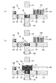
図9および図10は、第2実施形態にかかる成形体の製造方法を説明するための図(縦断面図)である。
Second Embodiment
Next, 2nd Embodiment of the manufacturing method of the molded object of this invention, a shaping | molding apparatus, and the manufacturing method of a sintered compact is described.
FIG. 9 and FIG. 10 are views (longitudinal sectional views) for explaining a method for producing a molded body according to the second embodiment.
以下、第2実施形態にかかる成形体の製造方法および成形装置について説明するが、前記第1実施形態にかかる成形体の製造方法および成形装置との相違点を中心に説明し、同様の事項については、その説明を省略する。
図9(a)は、前記第1実施形態における工程[4]に対応する図5(d)に相当する図である。
Hereinafter, a method for manufacturing a molded body and a molding apparatus according to the second embodiment will be described, but differences from the method for manufacturing the molded body and the molding apparatus according to the first embodiment will be mainly described, and similar matters will be described. The description is omitted.
FIG. 9A is a diagram corresponding to FIG. 5D corresponding to step [4] in the first embodiment.
本実施形態にかかる成形装置1では、図9(a)に示すように、前記第1実施形態にかかる成形装置1からコイル63が省略されている。このため、前記工程[4]において、上パンチ14の下面には、第1の造粒粉末51が吸着しない。なお、本実施形態にかかる成形装置1は、図9(a)に示すように、ダイ12上に、ダイ12を加振する加振装置128を有している。
In the
次に、図9(b)に示すように、フィーダボックス161内の第1の造粒粉末51を取り出し、第2の造粒粉末52に入れ替える。
次に、図9(c)に示すように、各コイル61、62に電圧を印加した状態で、フィーダボックス161を、キャビティ15の上方に至るまで左側に移動させる。これにより、図10(d)に示すように、フィーダボックス161内の第2の造粒粉末52が、キャビティ15に供給され、充填される。
Next, as shown in FIG. 9B, the first
Next, as shown in FIG. 9C, the
次に、フィーダボックス161を元の位置に戻した後、加振装置128により、ダイ12を振動させる。これにより、キャビティ15内に充填された第1の造粒粉末51および第2の造粒粉末52の密度を高め、その体積を減少させる。
次に、フィーダボックス161内の第2の造粒粉末52を取り出し、再び、第1の造粒粉末51に入れ替える。そして、図10(e)に示すように、フィーダボックス161を、キャビティ15の上方に至るまで左側に移動させる。これにより、図10(f)に示すように、フィーダボックス161内の第1の造粒粉末51が、キャビティ15に供給され、充填される。
次に、成形型10を型閉め状態とすることにより、キャビティ15内に複合成形体7が得られる。
Next, after the
Next, the second
Next, the composite molded body 7 is obtained in the
以上のような成形体の製造方法および成形装置によっても、前記第1実施形態と同様の作用・効果が得られる。
以上、本発明の成形体の製造方法、成形装置および焼結体の製造方法について、好適な実施形態に基づいて説明したが、本発明はこれに限定されるものではない。
また、前記実施形態にかかる成形体の製造方法および焼結体の製造方法では、必要に応じて、任意の工程を追加することもできる。
The same operations and effects as those of the first embodiment can also be obtained by the method for manufacturing a molded body and the molding apparatus as described above.
As mentioned above, although the manufacturing method of the molded object of this invention, the shaping | molding apparatus, and the manufacturing method of the sintered compact were demonstrated based on suitable embodiment, this invention is not limited to this.
Moreover, in the manufacturing method of the molded object and the manufacturing method of a sintered compact concerning the said embodiment, arbitrary processes can also be added as needed.
1……成形装置 2……フレーム 3……パンチ固定テーブル 31……貫通孔 4……プレート 41……貫通孔 5……粉末 51……第1の造粒粉末 52……第2の造粒粉末 10……成形型 11……貫通孔 12……ダイ 121、122……ダイセット 123……ガイドポスト 124……ダイセット連結板 125……シリンダロッド 126……下部油圧シリンダ 127……ガイドポスト 128……加振装置 13……下パンチ 131……ベースプレート 132……支柱 133……貫通孔 14……上パンチ 141……上パンチプレート 142……シリンダロッド 143……上部油圧シリンダ 144……貫通孔 15……キャビティ 16……粉末供給部 161……フィーダボックス 162……油圧シリンダ 163……シリンダロッド 61、62、63……コイル 610、620、630……電源回路 7……複合成形体 71……被覆層 72……本体部 80、90……チョークコイル 81、91……磁心 82、92……導線
DESCRIPTION OF
Claims (7)
成形型のキャビティ内に、前記第1の粉末とバインダとを含む第1の組成物を供給するとともに、前記第1の組成物を前記キャビティの内壁面に沿って配置する第1の工程と、
前記内壁面に沿って配置した前記第1の組成物の内側のキャビティ内に、前記第2の粉末とバインダとを含む第2の組成物を供給する第2の工程と、
前記キャビティ内に供給した前記第1の組成物と前記第2の組成物とを同時に加圧成形し、前記複合成形体を得る第3の工程と、を有し、
前記第1の粉末は、軟磁性材料で構成され、かつ前記第2の粉末よりも耐食性に優れたものであり、
前記第1の工程において、前記キャビティに磁界を付与することにより、着磁作用により前記第1の組成物を前記キャビティの内壁面に沿って配置することを特徴とする成形体の製造方法。 A main body composed of a pressure-molded body of the second powder, and a pressure-molded body of the first powder different from the second powder, formed so as to cover the outer surface of the main body. A method for producing a composite molded body having a coating layer,
Into the mold cavity, a first step of disposing said supplies first composition a comprising first powder and a binder, said first composition along the inner wall surface of the cavity,
The inner cavity of the first composition which is disposed along the inner wall surface, a second step of supplying a second composition comprising a second powder and a binder,
Wherein said supplied into the cavity first composition and said second composition simultaneously compacting, anda third step of obtaining the composite compact,
The first powder is made of a soft magnetic material, and has better corrosion resistance than the second powder,
In the first step, by applying a magnetic field to the cavity, the first composition is disposed along the inner wall surface of the cavity by a magnetizing action .
前記第3の工程の後、さらに、前記バインダを固化する工程を有する請求項1に記載の成形体の製造方法。 As the binder, a thermosetting binder is used,
After the third step, furthermore, the production method of the molded article according to claim 1 comprising the step of solidifying the binder.
前記複合成形体は、その内部に、コイル状に成形された導線を埋設した状態で成形されることにより、圧粉磁心用の成形体として得られる請求項1または2に記載の成形体の製造方法。3. The molded body according to claim 1, wherein the composite molded body is obtained as a molded body for a dust core by being molded in a state where a conductive wire formed in a coil shape is embedded therein. Method.
前記キャビティ内に、磁性材料で構成された第1の粉末と、該第1の粉末と異なる第2の粉末とを供給する粉末供給手段と、
前記ダイ、前記下パンチおよび前記上パンチのそれぞれに設けられたコイルと、該コイルに電圧を印加し得る電源回路と、を備え、前記キャビティ内に供給された前記第1の粉末が、前記キャビティの内壁面に吸着するように、前記キャビティに磁界を付与する磁界付与手段と、を有し、
前記キャビティ内に前記第1の粉末を供給するとともに、前記キャビティに磁界を付与して前記内壁面に前記第1の粉末を吸着させた後、前記キャビティ内に前記第2の粉末を供給して成形することにより、前記第2の粉末の成形体で構成された本体部と、該本体部の外表面を覆うように形成され、前記第1の粉末の成形体で構成された被覆層とを有する複合成形体を製造するよう構成されたことを特徴とする成形装置。 A die constituting the side surface of the cavity, a lower punch constituting the lower surface of the cavity and movable relative to the die, an upper surface of the cavity constituting the cavity, and moving relative to the die A mold comprising an upper punch ,
A powder supply means for supplying a first powder made of a magnetic material and a second powder different from the first powder into the cavity;
A coil provided in each of the die, the lower punch and the upper punch, and a power supply circuit capable of applying a voltage to the coil, wherein the first powder supplied into the cavity is the cavity to adsorb to the inner wall surface of, anda magnetic field applying means for applying a magnetic field to the cavity,
The first powder is supplied into the cavity, and a magnetic field is applied to the cavity to adsorb the first powder to the inner wall surface, and then the second powder is supplied into the cavity. By molding, a main body portion formed of the second powder molded body, and a coating layer formed to cover the outer surface of the main body portion and configured of the first powder molded body. A molding apparatus configured to produce a composite molded body having the same.
前記成形型が型開き状態にあるときに、前記コイルに通電されることによって、前記上パンチの下面に前記第1の粉末を吸着するよう構成されている請求項5に記載の成形装置。The molding apparatus according to claim 5, wherein the first powder is adsorbed to a lower surface of the upper punch by energizing the coil when the molding die is in an open state.
前記第2の粉末の焼結体で構成された本体部と、該本体部の外表面を覆うように形成され、前記第1の粉末の焼結体で構成された被覆層とを有する複合焼結体を製造することを特徴とする焼結体の製造方法。 A step of firing the molded body manufactured by the method for manufacturing a molded body according to any one of claims 1 to 4,
Composite firing comprising a main body portion made of a sintered body of the second powder and a coating layer formed to cover the outer surface of the main body portion and made of the sintered body of the first powder. A method for producing a sintered body, which comprises producing a bonded body.
Priority Applications (1)
| Application Number | Priority Date | Filing Date | Title |
|---|---|---|---|
| JP2007095964A JP4882834B2 (en) | 2007-04-02 | 2007-04-02 | Method for manufacturing molded body, molding apparatus, and method for manufacturing sintered body |
Applications Claiming Priority (1)
| Application Number | Priority Date | Filing Date | Title |
|---|---|---|---|
| JP2007095964A JP4882834B2 (en) | 2007-04-02 | 2007-04-02 | Method for manufacturing molded body, molding apparatus, and method for manufacturing sintered body |
Publications (3)
| Publication Number | Publication Date |
|---|---|
| JP2008258235A JP2008258235A (en) | 2008-10-23 |
| JP2008258235A5 JP2008258235A5 (en) | 2010-05-20 |
| JP4882834B2 true JP4882834B2 (en) | 2012-02-22 |
Family
ID=39981542
Family Applications (1)
| Application Number | Title | Priority Date | Filing Date |
|---|---|---|---|
| JP2007095964A Active JP4882834B2 (en) | 2007-04-02 | 2007-04-02 | Method for manufacturing molded body, molding apparatus, and method for manufacturing sintered body |
Country Status (1)
| Country | Link |
|---|---|
| JP (1) | JP4882834B2 (en) |
Cited By (1)
| Publication number | Priority date | Publication date | Assignee | Title |
|---|---|---|---|---|
| CN105082344A (en) * | 2015-09-10 | 2015-11-25 | 贵州友仁建材科技开发有限公司 | Manufacturing method and device for improving surface quality of brick |
Families Citing this family (7)
| Publication number | Priority date | Publication date | Assignee | Title |
|---|---|---|---|---|
| JP5642029B2 (en) * | 2011-07-07 | 2014-12-17 | 三菱電機株式会社 | Rare earth magnet separation and recovery method, rare earth magnet manufacturing method, and rotating electrical machine manufacturing method |
| CN103158197B (en) * | 2011-12-27 | 2015-09-16 | 北京仁创科技集团有限公司 | A kind of formation system of composite structural brick |
| CN103171045B (en) * | 2011-12-27 | 2015-09-16 | 北京仁创科技集团有限公司 | A kind of moulding process of composite structural brick |
| CN103660012B (en) * | 2013-11-18 | 2015-12-23 | 宜兴市明月建陶有限公司 | A kind of dry powder tile system and system watt method thereof |
| JP6213402B2 (en) * | 2014-07-08 | 2017-10-18 | トヨタ自動車株式会社 | Method for manufacturing sintered body |
| CN106696068B (en) * | 2015-07-23 | 2019-01-04 | 佛山市东鹏陶瓷有限公司 | A kind of cloth system and its distributing method with surrounding edge structural ceramics brick |
| CN113539668B (en) * | 2021-06-18 | 2023-10-03 | 宁波中科毕普拉斯新材料科技有限公司 | Coil packaging manufacturing method of inductor |
Family Cites Families (4)
| Publication number | Priority date | Publication date | Assignee | Title |
|---|---|---|---|---|
| JPS5220903A (en) * | 1975-08-11 | 1977-02-17 | Akitoshi Furuhata | Process and apparatus for molding of metal powder for two-layered meta l |
| JPH0897028A (en) * | 1994-09-29 | 1996-04-12 | Taiyo Yuden Co Ltd | Manufacture of ceramic material molded body for electronic part |
| JP2004014773A (en) * | 2002-06-06 | 2004-01-15 | Matsushita Electric Ind Co Ltd | Ferrite core, magnetic field producing device using the same, and method of manufacturing magnetic field producing device |
| JP2004319749A (en) * | 2003-04-16 | 2004-11-11 | Kobe Steel Ltd | Metal powder for pressed powder magnetic core, method for manufacturing the same and method for manufacturing the same |
-
2007
- 2007-04-02 JP JP2007095964A patent/JP4882834B2/en active Active
Cited By (1)
| Publication number | Priority date | Publication date | Assignee | Title |
|---|---|---|---|---|
| CN105082344A (en) * | 2015-09-10 | 2015-11-25 | 贵州友仁建材科技开发有限公司 | Manufacturing method and device for improving surface quality of brick |
Also Published As
| Publication number | Publication date |
|---|---|
| JP2008258235A (en) | 2008-10-23 |
Similar Documents
| Publication | Publication Date | Title |
|---|---|---|
| JP4882834B2 (en) | Method for manufacturing molded body, molding apparatus, and method for manufacturing sintered body | |
| KR102121181B1 (en) | Method of manufacturing soft magnetic dust core and soft magnetic dust core | |
| JP2009088502A (en) | Method of manufacturing oxide-coated soft magnetic powder, oxide-coated soft magnetic powder, dust core, and magnetic element | |
| JPH10163055A (en) | Manufacture of high electric resistance rare earth permanent magnet | |
| JP4803094B2 (en) | Powder magnetic core and magnetic element | |
| JP2010010426A (en) | Inductor and method of manufacturing the same | |
| CN113941704A (en) | Electromagnetic induction heating layer and preparation method thereof, and atomization core and preparation method thereof | |
| WO2018088393A1 (en) | Method for producing rare earth magnet | |
| JP2013110225A (en) | Magnetic member and manufacturing method therefor | |
| JP2017041507A (en) | Dust core and electronic/electric component having the dust core, and electronic/electric equipment on which the electronic/electric component is mounted | |
| JP2015008200A (en) | Method of manufacturing magnet and magnet | |
| JP2001068317A (en) | Nd-Fe-B SINTERED MAGNET AND ITS MANUFACTURING METHOD | |
| JP2007123376A (en) | Compound magnetic substance and magnetic device using same, and method of manufacturing same | |
| JP5342946B2 (en) | Ceramic structure and manufacturing method thereof | |
| JPH09283358A (en) | Manufacture of r-fe-b sintered magnet | |
| JP4923149B2 (en) | Permanent magnet and method for manufacturing permanent magnet | |
| JP5469316B2 (en) | Ceramic structure and manufacturing method thereof | |
| JP5501826B2 (en) | Manufacturing method of rare earth sintered magnet | |
| JP4302498B2 (en) | Method for manufacturing isotropic magnet and magnet thereof | |
| JP2006294733A (en) | Inductor and its manufacturing method | |
| KR20190079687A (en) | The present invention relates to a compacted core, a method for producing the compacted core, an electric / electronic component having the compacted core, and an electric / electronic device | |
| JP2006100292A (en) | Dust core manufacturing method and dust core manufactured thereby | |
| JP2006108475A (en) | Process for producing soft magnetic material | |
| JP2009272615A (en) | Dust core, and manufacturing method thereof | |
| KR20170137968A (en) | Manufacturing method of power inductor |
Legal Events
| Date | Code | Title | Description |
|---|---|---|---|
| A521 | Written amendment |
Free format text: JAPANESE INTERMEDIATE CODE: A523 Effective date: 20100401 |
|
| A621 | Written request for application examination |
Free format text: JAPANESE INTERMEDIATE CODE: A621 Effective date: 20100401 |
|
| A977 | Report on retrieval |
Free format text: JAPANESE INTERMEDIATE CODE: A971007 Effective date: 20110707 |
|
| A131 | Notification of reasons for refusal |
Free format text: JAPANESE INTERMEDIATE CODE: A131 Effective date: 20110712 |
|
| A521 | Written amendment |
Free format text: JAPANESE INTERMEDIATE CODE: A523 Effective date: 20110829 |
|
| TRDD | Decision of grant or rejection written | ||
| A01 | Written decision to grant a patent or to grant a registration (utility model) |
Free format text: JAPANESE INTERMEDIATE CODE: A01 Effective date: 20111108 |
|
| A01 | Written decision to grant a patent or to grant a registration (utility model) |
Free format text: JAPANESE INTERMEDIATE CODE: A01 |
|
| A61 | First payment of annual fees (during grant procedure) |
Free format text: JAPANESE INTERMEDIATE CODE: A61 Effective date: 20111121 |
|
| FPAY | Renewal fee payment (event date is renewal date of database) |
Free format text: PAYMENT UNTIL: 20141216 Year of fee payment: 3 |
|
| R150 | Certificate of patent or registration of utility model |
Ref document number: 4882834 Country of ref document: JP Free format text: JAPANESE INTERMEDIATE CODE: R150 Free format text: JAPANESE INTERMEDIATE CODE: R150 |
|
| S531 | Written request for registration of change of domicile |
Free format text: JAPANESE INTERMEDIATE CODE: R313531 |
|
| R350 | Written notification of registration of transfer |
Free format text: JAPANESE INTERMEDIATE CODE: R350 |