JP4858848B2 - Interdigit connection device - Google Patents

Interdigit connection device Download PDF

Info

Publication number
JP4858848B2
JP4858848B2 JP2007102580A JP2007102580A JP4858848B2 JP 4858848 B2 JP4858848 B2 JP 4858848B2 JP 2007102580 A JP2007102580 A JP 2007102580A JP 2007102580 A JP2007102580 A JP 2007102580A JP 4858848 B2 JP4858848 B2 JP 4858848B2
Authority
JP
Japan
Prior art keywords
girder
plate
latch plate
casing
kipu
Prior art date
Legal status (The legal status is an assumption and is not a legal conclusion. Google has not performed a legal analysis and makes no representation as to the accuracy of the status listed.)
Expired - Fee Related
Application number
JP2007102580A
Other languages
Japanese (ja)
Other versions
JP2008261099A (en
Inventor
宏一 渡辺
伸治 真瀬
豊 中村
岳彦 寺田
和彦 森川
一博 吉田
Current Assignee (The listed assignees may be inaccurate. Google has not performed a legal analysis and makes no representation or warranty as to the accuracy of the list.)
Shimizu Corp
Original Assignee
Shimizu Corp
Priority date (The priority date is an assumption and is not a legal conclusion. Google has not performed a legal analysis and makes no representation as to the accuracy of the date listed.)
Filing date
Publication date
Application filed by Shimizu Corp filed Critical Shimizu Corp
Priority to JP2007102580A priority Critical patent/JP4858848B2/en
Publication of JP2008261099A publication Critical patent/JP2008261099A/en
Application granted granted Critical
Publication of JP4858848B2 publication Critical patent/JP4858848B2/en
Expired - Fee Related legal-status Critical Current
Anticipated expiration legal-status Critical

Links

Images

Landscapes

  • Bridges Or Land Bridges (AREA)

Description

本発明は桁間連結装置に係り、特に道路高架橋等の支承位置で橋桁間に取り付けられ、桁間の連続性を高め、振動や騒音の低減、地震時の桁に生じる被害の軽減を図ることができる桁間連結装置に関する。   The present invention relates to a connecting device between girders, and is particularly installed between bridge girders at a support position such as a road viaduct. The present invention relates to an interdigit connecting device capable of performing the above.

高速道路などの高架橋においては、車両の通行によって生じる交通振動が問題となることがある。従来の高架橋は、経済性を考えて、単純合成桁を橋脚間に架設した構造形式が多く建設されている。最近では車両の走行性向上やジョイント部の維持管理の簡略化等の理由から、多径間連続橋が採用されることも多くなった。しかし、連続橋では温度応力による影響を防止するために、桁の軸方向伸縮変形を吸収する構造を設ける必要があり、連続橋であっても、一定の長さごとに桁間に隙間構造が設けられている。一方、交通振動は、桁間のつなぎ目で発生してることが知られており、桁のつなぎ目を連続化することを目的とした提案も多数なされている。   In a viaduct such as an expressway, traffic vibration caused by vehicle traffic may be a problem. Many conventional viaducts have been constructed with a simple composite girder installed between bridge piers in consideration of economy. Recently, multi-span continuous bridges have been increasingly adopted for reasons such as improved vehicle running performance and simplified maintenance of joints. However, in order to prevent the influence of temperature stress on the continuous bridge, it is necessary to provide a structure that absorbs the axial expansion and contraction deformation of the girder. Even in the continuous bridge, there is a gap structure between the girder for every fixed length. Is provided. On the other hand, it is known that traffic vibrations occur at the joints between girders, and many proposals have been made for the purpose of making the joints between girders continuous.

埋設ジョイントは、舗装面をつなぎ目を平滑にすることが可能な路面部の連結構造であり、車両がつなぎ目を通過する際の騒音および振動をある程度、低減することができる。しかし、ジョイント部を跨いで車両荷重の飛び移りそのものは発生してしまうため、桁を直接連結した場合に比べ、その低減効果は小さい。また、地震時の落橋防止に対する対策としての効果も小さい。   The buried joint is a road surface connecting structure that can smooth the joint of the pavement surface, and can reduce noise and vibration when the vehicle passes through the joint to some extent. However, since the vehicle load itself jumps across the joint portion, the reduction effect is small as compared with the case where the girders are directly connected. In addition, it has little effect as a measure for preventing falling bridges during an earthquake.

一方、桁を連結(ノージョイント化)すれば、交通振動は大幅に低減することができるので、単純桁の連結を目的とした工法も多数提案されている。これらの提案の目的は、交通振動低減、つなぎ目の雨水対策、落橋防止、橋梁損傷時の復旧作業の容易さなど多岐にわたり、交通振動低減対策としての効果は大きい。しかし、温度応力の影響を大きく受けるため、ノージョイント化が可能な連続区間長には制限がある。   On the other hand, if the girders are connected (no-joint), traffic vibration can be greatly reduced, and many methods have been proposed for connecting simple girders. The purpose of these proposals is wide-ranging, such as traffic vibration reduction, rainwater countermeasures at joints, prevention of falling bridges, and ease of restoration work in the event of bridge damage. However, since it is greatly affected by temperature stress, there is a limit to the length of the continuous section that can be made jointless.

また、通常の車両通行時ではなく、大地震時の落橋防止のために橋桁を連結し、かつ免震性能を付与した装置も提案されている(特許文献1)。特許文献1に記載された装置では、橋脚上に載置された鋼桁の端部側部に、積層ゴムを介して連結プレートが取り付けられている。この装置により単純支持構造の鋼桁同士が連結されるようになっている。すなわち特許文献1に開示された積層ゴムは、せん断変形する部材として用いられている。地震時における鋼桁間の連続性は、縦長の略直方体形状積層ゴムのせん断変形により保持され、これにより落橋防止が図られる。この連結プレートからなる免震落橋防止装置は、地震時の大変形を対象として積層ゴムのせん断剛性等が設定されているため、車両通行時に生じる、交通振動のような微小変形の振動には効果があまり見込めない。   In addition, a device has been proposed in which bridge girders are connected and seismic isolation performance is provided to prevent a falling bridge during a major earthquake, not during normal vehicle traffic (Patent Document 1). In the device described in Patent Document 1, a connecting plate is attached to the end side portion of the steel beam placed on the pier via a laminated rubber. With this device, steel girders having a simple support structure are connected to each other. That is, the laminated rubber disclosed in Patent Document 1 is used as a member that undergoes shear deformation. The continuity between steel girders at the time of an earthquake is maintained by the shear deformation of a vertically long, substantially rectangular parallelepiped laminated rubber, thereby preventing a falling bridge. The seismic isolated bridge prevention device consisting of this connecting plate is effective for small deformation vibrations such as traffic vibrations that occur when vehicles are driven because the shear rigidity of laminated rubber is set for large deformations during earthquakes. Is not expected very much.

交通振動のような上下方向の微小振幅に対応させるためには、がたつきのない連結装置が有効である。所定の効果が得られる連結装置として、出願人はすでに、連結部材にアスファルト等の粘弾性材料を介装して桁間の連結を行うようにした制振高架橋(特許文献2)を提案している。この制振高架橋では、粘弾性体の粘性抵抗により微小振動にも振動減衰効果が期待できる。
特開平9−184111号公報参照。 特開2000−73311公報参照。
In order to cope with a minute amplitude in the vertical direction such as traffic vibration, a coupling device without rattling is effective. As a connecting device that can achieve a predetermined effect, the applicant has already proposed a vibration suppression viaduct (Patent Document 2) in which connecting members are connected to each other by a viscoelastic material such as asphalt. Yes. In this vibration suppression viaduct, a vibration damping effect can be expected even for minute vibrations due to the viscous resistance of the viscoelastic body.
See JP-A-9-184111. See JP 2000-73311 A.

ところで、上述の特許文献1,2に開示された装置は、ともに基本的に鋼桁側のベース部材と連結鋼板の側面に積層ゴムやアスファルトを介装させた構造となっている。交通振動を低減するためには、桁間をなるべく剛性の高い部材で連結することが有効であるが、特許文献1,2のように積層ゴムやアスファルトを介装させた構造では、せん断変形する部材として用いられているため、十分な剛性が確保できない。また、長スパンの桁においては、季節および昼夜の温度差に伴う桁の軸方向伸縮が生じるが、その際の桁端の可動量を十分、吸収可能な構造とする必要がある。そこで、本発明の目的は上述した従来の技術が有する問題点を解消し、橋脚梁部等の支承上に隣接して据え付けられる高架橋の桁間に生じる上下方向の変位拘束を果たすとともに、発生振動を減衰可能な構造を有する桁間連結装置を提供することにある。   By the way, the devices disclosed in the above-mentioned Patent Documents 1 and 2 basically have a structure in which laminated rubber or asphalt is interposed between the base member on the steel beam side and the side surface of the connecting steel plate. In order to reduce traffic vibration, it is effective to connect between the girders with a member having as high rigidity as possible. However, in a structure in which laminated rubber or asphalt is interposed as in Patent Documents 1 and 2, shear deformation occurs. Since it is used as a member, sufficient rigidity cannot be ensured. Further, in the long span girders, the axial expansion and contraction of the girders due to the temperature difference between the season and day and night occurs, but it is necessary to have a structure capable of sufficiently absorbing the movable amount of the girders at that time. Therefore, the object of the present invention is to solve the problems of the prior art described above, and to restrain the vertical displacement generated between the viaduct girders installed adjacent to the support such as the bridge pier part and the generated vibration. It is an object of the present invention to provide an inter-girder connecting device having a structure capable of damping the vibration.

上記目的を達成するために、本発明は支承上に隣接して支持された橋桁の一方の桁端部に取り付けられ、かんぬきとしての機能を奏するプレートと、かんぬき受けとして、前記プレートの一部を、その内部に挿入して保持する、他方の桁端部に取り付けられたプレート受け部とを備えた桁間連結装置であって、前記プレート受け部内に挿入されたプレートの全周が粘弾性体層を介して前記プレート受け部に保持されたことを特徴とする。 In order to achieve the above object, the present invention provides a plate that is attached to one end of a bridge girder supported adjacently on a bearing and that functions as a crown, and a part of the plate is used as a crown receiver. and holds inserted therein, the entire circumference of the other a digit between coupling device and a Plate receiving portion attached to girder end, before Kipu rate received inserted up rate portion There characterized in that it is held in Kipu rate receiving unit via the front viscoelastic layer.

記プレート受け部は、前記プレートの先端側全体を内部に収容し保持する扁平箱状ケーシングとすることが好ましい。 Before Kipu rate receiving unit is preferably a flat box-like casing before accommodating the tip side entire Kipu rate inside the holding.

記プレート受け部は、前記プレートの中間部位をフランジ部で保持する帯板状部材とすることが好ましい。 Before Kipu rate receiving unit, it is preferable that the strip-shaped member for holding the intermediate portion of the front Kipu rate flange.

前記粘弾性体層として、前記プレートと前記プレート受け部の隙間にゴム層を充填形することが好ましい。 As the viscoelastic layer, it is preferable to fill the form rubber layer in the gap before Kipu rate and the plate receiving portion.

記プレートの上下端部を面取りし、あるいは前記ケーシングの内周隅部に面当して、前記粘弾性体層に対しての応力集中を緩和させることが好ましい。 Chamfered upper and lower ends of the front Kipu rate, or in surface contact with the inner peripheral corner portion of the casing, it is preferable to relax the stress concentration with respect to the viscoelastic layer.

本発明によれば、橋脚等の支承上で、隣接して据え付けられる高架橋の橋桁間に生じる上下方向の変位を拘束できるとともに、部材間の応力伝達において粘弾性体層の作用により、桁間に生じる発生振動を減衰させる効果も奏することができる。   According to the present invention, the vertical displacement generated between adjacent bridge girders installed adjacent to each other can be constrained on the support of a bridge pier or the like. An effect of attenuating the generated vibration can also be achieved.

以下、本発明の桁間連結装置の実施するための最良の形態として、以下の実施例について添付図面を参照して説明する。   Hereinafter, as the best mode for carrying out the inter-beam connecting device of the present invention, the following embodiments will be described with reference to the accompanying drawings.

図1は、本発明の桁間連結装置10を、道路高架橋の単純桁1の桁連結箇所に適用した実施例を示した全体構造図である。図1に示したように、連結対象となる単純桁1A,1B(以下、単に桁1と記す。桁の区別をつける場合は符号A,Bを付記する。)は、橋脚2の梁部上面3に設置された沓座4上に、所定の間隙(クリアランス)を設けて可動支持されている。同図に示したように、この桁間連結装置10の構成部材としては、隣接した一方の桁1Aの側面に、この桁間において、一方の側から延在する「かんぬき(ラッチ:latch)」としての機能を果たす板状部材(プレート)11(以下、ラッチプレート11と記す。)が、他方の桁1Bの側面に、「かんぬき受け」として機能して、「かんぬき」を収容する扁平箱形状のケーシング21(機能面からは、ラッチプレートに対応させてラッチプレート受けと呼ぶ。)が取り付けられている。具体的には、桁間連結装置10として、一方の桁1Aのラッチプレート11の先端部11aが、他方の桁1Bのラッチプレート受けとしてのケーシング21内に挿入、収容される。このように、ラッチプレート11とケーシング21とは、桁間において「かんぬき」と「かんぬき受け」の役割を果たし、この係止状態が保持されて桁間が連結される。このとき、舗装部路面5位置には、収縮目地ジョイント6が配置され、桁に生じる温度伸縮等を吸収し、通行車両7の通過時の静粛化が図られている。

FIG. 1 is an overall structural diagram showing an embodiment in which the inter-girder connecting device 10 of the present invention is applied to a girder connecting portion of a simple girder 1 of a road viaduct. As shown in FIG. 1, the simple girder 1A, 1B (hereinafter simply referred to as girder 1; the symbols A and B are added to distinguish the girder) are the upper surface of the beam portion of the pier 2 as shown in FIG. A predetermined gap (clearance) is provided on the scorpio 4 installed at 3 and is movably supported. As shown in the figure, as a constituent member of the inter-girder coupling device 10, a “latch” extending from one side between the girder is provided on the side surface of one adjacent girder 1A. A plate-like member (plate) 11 (hereinafter referred to as a latch plate 11) that functions as a flat box shape that functions as a “pin holder” on the side surface of the other beam 1 B and accommodates the “pin”. A casing 21 (referred to as a latch plate receiver corresponding to the latch plate from the functional aspect) is attached. Specifically, as the inter-girder coupling device 10, the leading end portion 11a of the latch plate 11 of one girder 1A is inserted and accommodated in a casing 21 as a latch plate receiver of the other girder 1B. In this way, the latch plate 11 and the casing 21 serve as “canning” and “canning receiving” between the girders, and this latching state is maintained to connect the girders. At this time, a shrink joint joint 6 is arranged at the pavement portion road surface 5 position to absorb temperature expansion and contraction and the like occurring in the girders, so that the passage vehicle 7 can be quieted.

図2は、桁1に取り付けられた桁間連結装置10の構成を示した部分拡大斜視図である。同図に示した桁1として、本実施例では鋼製箱桁が使用されている。この鋼製箱桁の側面に、厚板長方形状をなすラッチプレート11が8本の取付ボルト8によって固定されている。ラッチプレート11の先端は、取り付けられた桁端から、隣接した桁側に突出している。ラッチプレート11の取付に際しては、桁側面とラッチプレート11との間にスペーサプレート12を介装してラッチプレート11を桁1Aの側面に固定することにより、ラッチプレート11を桁外側面から所定の離れだけ離し、ラッチプレート11を後述するケーシング21の挿入用の開口部24に収容させることができる。本実施例では、ラッチプレート11には、高さ1000mm,橋軸方向長さ2000mm,板厚30mmの一般構造用鋼板(SS400)が用いられている。   FIG. 2 is a partially enlarged perspective view showing the configuration of the inter-girder coupling device 10 attached to the girder 1. As the girder 1 shown in the figure, a steel box girder is used in this embodiment. A latch plate 11 having a thick plate rectangular shape is fixed to the side surface of the steel box girder by eight mounting bolts 8. The tip of the latch plate 11 protrudes from the attached beam end to the adjacent beam side. When the latch plate 11 is attached, the latch plate 11 is fixed to the side surface of the spar 1A with a spacer plate 12 interposed between the side surface of the spar and the latch plate 11, so that the latch plate 11 is fixed to the predetermined side from the outer side surface of the spar. The latch plate 11 can be accommodated in the opening 24 for insertion of the casing 21, which will be described later. In this embodiment, the latch plate 11 is a general structural steel plate (SS400) having a height of 1000 mm, a bridge axis length of 2000 mm, and a plate thickness of 30 mm.

一方、ラッチプレート11が取り付けられた桁1Aと連続する隣接の桁1Bの側面には、ケーシング21が取り付けられている。本実施例では、ケーシング21は、図2に示したように、内部に挿入されたラッチプレート11を保持可能な、両端面が開放された扁平な箱状をなし、外形高さ1120mm,橋軸方向長さ800mmで、板厚40mmの一般構造用鋼板(SS400)を加工して製作されたもので、ベースプレート22を介して桁側面に取り付けられている。ケーシング21の内法寸法は、図3(b)に示したように、ラッチプレート11の移動量(=橋梁供用時における桁の想定伸縮量)に応じて決定されるが、本実施例では、ラッチプレート11が収容された状態で、その全周囲に少なくとも2cmの隙間23が設けられている。その隙間23にはラッチプレート11が収容された状態で、ラッチプレート11の全周にわたり、ゴム層31がラッチプレート11とケーシング21の内面と一体をなして形成されている。このゴム層31は、あらかじめラッチプレート11をケーシング21にセットした状態でラッチプレート11の周囲に均一な厚さをなすように、スペーサ28(図11参照)を埋設してラッチプレート11の位置保持が図られ、流動状のゴム素材を隙間に充填して所定の粘弾性状体とし、ラッチプレート11の全周を完全に被覆したものである。ゴム素材としては、天然ゴム、各種合成ゴム、高減衰ゴム等を使用することができる。ラッチプレート11は、ケーシング21内に位置する部位の両側面及び上下面の全周がゴム層31で覆われているため、両側面及び上下面でラッチプレート11の変形に応じたせん断抵抗、引張圧縮抵抗を発揮することができる。すなわち、橋軸方向に関する水平方向変位に加え、この連結位置で、一方の桁1Aが支承位置を支点として、スパン中央が上下方向に撓むように変位する現象が生じた場合、支点の近傍に設けられた桁間連結装置10に面内ねじれせん断力が生じるが、ケーシング21の上下面でラッチプレート11の変位を有効に拘束できるため、面内ねじれせん断力によって生じる上下面での引張圧縮作用に対する抵抗性も有する。   On the other hand, a casing 21 is attached to the side face of the adjacent girder 1B continuous with the girder 1A to which the latch plate 11 is attached. In the present embodiment, as shown in FIG. 2, the casing 21 has a flat box shape that can hold the latch plate 11 inserted therein and has both end faces open, has an outer height of 1120 mm, and a bridge shaft. It is manufactured by processing a general structural steel plate (SS400) having a direction length of 800 mm and a thickness of 40 mm, and is attached to the side surface of the girder via the base plate 22. As shown in FIG. 3B, the internal dimensions of the casing 21 are determined according to the amount of movement of the latch plate 11 (= the expected extension / contraction amount of the girder when the bridge is in service). In this embodiment, In a state where the latch plate 11 is accommodated, a gap 23 of at least 2 cm is provided around the entire periphery. A rubber layer 31 is formed integrally with the latch plate 11 and the inner surface of the casing 21 over the entire circumference of the latch plate 11 in a state where the latch plate 11 is accommodated in the gap 23. The rubber layer 31 is embedded with spacers 28 (see FIG. 11) so as to have a uniform thickness around the latch plate 11 in a state where the latch plate 11 is set in the casing 21 in advance, so that the position of the latch plate 11 is maintained. A fluid rubber material is filled in the gap to form a predetermined viscoelastic body, and the entire circumference of the latch plate 11 is completely covered. As the rubber material, natural rubber, various synthetic rubbers, high damping rubber, or the like can be used. Since the latch plate 11 is covered with the rubber layer 31 on both sides and upper and lower surfaces of the portion located in the casing 21, the shear resistance and tension according to the deformation of the latch plate 11 on both sides and the upper and lower surfaces. Compression resistance can be exhibited. In other words, in addition to the horizontal displacement in the bridge axis direction, if a phenomenon occurs in which one girder 1A is displaced so that the center of the span bends in the vertical direction with the bearing position as a fulcrum, it is provided near the fulcrum. Although an in-plane torsional shear force is generated in the inter-girder coupling device 10, the displacement of the latch plate 11 can be effectively restrained on the upper and lower surfaces of the casing 21. It also has sex.

ここで、ケーシング21内に形成された粘弾性抵抗体としてのゴム層31の作用について説明する。ケーシング21内に収容されたラッチプレート11とケーシング21内面との間の隙間には上述したように、ゴム層31が形成されている。このとき、ラッチプレート11とゴム層31のゴム素材とは十分に密着し、ラッチプレート11がケーシング21内を橋軸方向に変位したとき、ゴム素材はラッチプレート11の変形量に追従したせん断変形を示す。このラッチプレート11とケーシング21内面との間の隙間(ゴム層31の層厚)t(図3(b)参照)は、材料温度変動による桁の変位量(伸縮量)と、ゴム素材に設定された許容せん断変形角とから設定することができる。すなわち、許容せん断変形角がα%であるとき、温度変動による桁間の変位量をΔ(mm)とすると、ゴム層31の厚さtは最小厚さtmin以上となるようにすればよい。
min=100×Δ/α(mm)
たとえば、使用ゴムの許容せん断変形角150%、桁変位量Δ=30mmと設定した場合、ゴム層31の最小厚さを20mmとすることができる。
Here, the operation of the rubber layer 31 as a viscoelastic resistor formed in the casing 21 will be described. As described above, the rubber layer 31 is formed in the gap between the latch plate 11 housed in the casing 21 and the inner surface of the casing 21. At this time, the latch plate 11 and the rubber material of the rubber layer 31 are sufficiently adhered to each other, and when the latch plate 11 is displaced in the casing 21 in the bridge axis direction, the rubber material is subjected to shear deformation following the deformation amount of the latch plate 11. Indicates. A gap (layer thickness of the rubber layer 31) t (see FIG. 3B) between the latch plate 11 and the inner surface of the casing 21 is set to a displacement amount (expansion / contraction amount) of a girder due to a material temperature variation and a rubber material. The allowable shear deformation angle can be set. That is, when the allowable shear deformation angle is α%, the thickness t of the rubber layer 31 may be equal to or greater than the minimum thickness t min , where Δ (mm) is the displacement between digits due to temperature fluctuation. .
t min = 100 × Δ / α (mm)
For example, when the allowable shear deformation angle of the rubber used is set to 150% and the girder displacement amount Δ = 30 mm, the minimum thickness of the rubber layer 31 can be set to 20 mm.

また、隣接した桁1A,1Bがこの桁間連結装置10を取り付けた桁端の支承を支点として、桁のスパン中央が上下に撓むような変位が生じた際、ラッチプレート11の上下に位置するゴム層31の一方が圧縮抵抗部材として、他方が引張抵抗部材として作用する。このとき側面板により側方変位も拘束されるため、ゴム材はほぼ非圧縮性の素材であるので、ゴム層31の剛性が増大し、ラッチプレート11の変位を有効に拘束することができる。また、ラッチプレートは、上下方向の寸法が大きな板形状であるため、桁間連結装置10で連結された桁1A,1Bは上下方向に関しても、応力伝達可能に連結された構造として挙動する。   Also, adjacent girders 1A and 1B are positioned above and below the latch plate 11 when a displacement occurs such that the center of the span of the girders bends up and down with the support at the end of the girders to which the interdigit connecting device 10 is attached as fulcrums. One of the rubber layers 31 acts as a compression resistance member and the other acts as a tension resistance member. At this time, since the lateral displacement is also restrained by the side plate, the rubber material is an almost incompressible material, so that the rigidity of the rubber layer 31 is increased and the displacement of the latch plate 11 can be effectively restrained. In addition, since the latch plate has a plate shape with a large vertical dimension, the girders 1A and 1B coupled by the inter-girder coupling device 10 behave as a structure coupled so as to be able to transmit stress in the vertical direction.

なお、上述の剛性増加に比べ、ラッチプレート11の面外方向については、板材であるラッチプレート11の曲げ剛性が小さいために、上下方向よりも連結効果が小さくなる。その結果として、桁間連続装置10を面外方向に剥離させる力が小さくなり、桁間連続装置と橋桁との取付ボルト等の取付部材の数量を少なくできる効果もある。桁間連続装置10に面内ねじれせん断力が生じた場合、ケーシング21の開放縁において局所的に大きな応力が発生する。ケーシングの破壊を防ぐために、ケーシング21を補剛することが好ましい。図4は、その補剛例を示した斜視図である。同図に示したように、ケーシング21の開放縁側の外周に側面視して略コ字形をなす補強鋼材25を付加することにより、開口部24において、開口部24がラッチプレート11の移動に追従して変形するのを防止することができる。図示した補強部材25は、ケーシング21の外側に増設するように付加されたものであるが、あらかじめ開口部24の厚さを増した構造のケーシング21を加工製作することもできる。また、図4では、両側の開口部24に補強部材を設けたが、桁スパンの中央付近での上下振動の影響により、支点位置としての桁端に設けられたラッチプレート11が取付け部を中心として面内回転するような動作を示す場合が想定される。そのような挙動に対しては、ラッチプレート11の先端側のみに補強鋼材25を取り付けることで対応することができる。   In addition, compared to the above-described increase in rigidity, in the out-of-plane direction of the latch plate 11, since the bending rigidity of the latch plate 11 that is a plate material is small, the coupling effect is smaller than in the vertical direction. As a result, the force for peeling the inter-girder continuous device 10 in the out-of-plane direction is reduced, and there is an effect that the number of mounting members such as mounting bolts between the inter-girder continuous device and the bridge girder can be reduced. When an in-plane torsional shear force is generated in the inter-girder continuous device 10, a large stress is locally generated at the open edge of the casing 21. In order to prevent destruction of the casing, it is preferable to stiffen the casing 21. FIG. 4 is a perspective view showing an example of the stiffening. As shown in the figure, the opening 24 follows the movement of the latch plate 11 in the opening 24 by adding a reinforcing steel material 25 having a substantially U-shape in side view to the outer periphery of the open edge side of the casing 21. And can be prevented from being deformed. The illustrated reinforcing member 25 is added to the outside of the casing 21, but the casing 21 having a structure in which the thickness of the opening 24 is increased can be processed and manufactured. In FIG. 4, the reinforcing members are provided in the openings 24 on both sides. However, the latch plate 11 provided at the end of the spar as the fulcrum position is centered on the attachment part due to the influence of vertical vibration near the center of the spar span. Assuming a case where an in-plane rotation operation is shown. Such behavior can be dealt with by attaching the reinforcing steel material 25 only to the front end side of the latch plate 11.

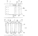
一方、桁間連結装置10位置での面内せん断力の作用が小さいことが想定される場合には、ラッチプレート11の橋軸方向の水平変位をスムースに支持するとともに、面内せん断変形に対して最小限の変位拘束が可能であればよい。そこで、図5各図に示したように、ケーシング21に代えて、ラッチプレート受け部材とし、縦長形状の帯状体の受け部材26を桁側面に取り付けて、この受け部材26のフランジ26aとラッチプレート11との隙間にゴム層31を形成し、ラッチプレート11の先端側を、ラッチプレート受け部材のフランジ位置で移動可能に保持することも可能である。   On the other hand, when it is assumed that the action of the in-plane shearing force at the position of the inter-girder connecting device 10 is small, the horizontal displacement in the bridge axis direction of the latch plate 11 is smoothly supported, and against the in-plane shear deformation. As long as the minimum displacement constraint is possible. Therefore, as shown in FIGS. 5A and 5B, instead of the casing 21, a latch plate receiving member is used, and a vertically long belt-like receiving member 26 is attached to the side of the beam. The flange 26a of the receiving member 26 and the latch plate It is also possible to form a rubber layer 31 in the gap between the latch plate 11 and the front end side of the latch plate 11 so as to be movable at the flange position of the latch plate receiving member.

図5(a)は、図3(a)に示した場合と同等のラッチプレート11を桁の一方に取り付け、その先端側を、隣接した桁の側面に平行に取り付けた2本のラッチ受け部材26のフランジ26aで支持する桁間連結装置10の構成を示している。図5(b)は、隣接する桁1A,1Bにそれぞれ取り付けられたラッチ受け部材26,26…のみで、ラッチプレート11を支持した構成を示している。この構成では、図3,図5(a)に示したように、ラッチプレート11自体が桁1に固定されないので、すべてのラッチ受け部材26,26…に形成されたゴム層31により、桁1に生じた橋軸方向の変位量に伴うラッチプレート11のずれを吸収するとともに、上下方向の変位に対しては十分な剛性を確保している。なお、ラッチプレート11の橋軸方向の端部にはストッパフランジ27が形成されており、ラッチプレート11に過大な変位量が生じたときにラッチプレート11がラッチ受け部材26から脱落するのを防止できる。   FIG. 5 (a) shows two latch receiving members in which a latch plate 11 equivalent to that shown in FIG. 3 (a) is attached to one of the girders and the tip side is attached in parallel to the side face of the adjacent girders. The structure of the inter-girder coupling device 10 supported by the 26 flanges 26a is shown. FIG. 5 (b) shows a configuration in which the latch plate 11 is supported only by the latch receiving members 26, 26... Attached to the adjacent girders 1A, 1B, respectively. In this configuration, as shown in FIG. 3 and FIG. 5A, the latch plate 11 itself is not fixed to the beam 1. Therefore, the rubber layer 31 formed on all the latch receiving members 26, 26. In addition to absorbing the displacement of the latch plate 11 due to the amount of displacement in the direction of the bridge axis, sufficient rigidity is secured against displacement in the vertical direction. A stopper flange 27 is formed at the end of the bridge plate 11 in the bridge axis direction to prevent the latch plate 11 from dropping from the latch receiving member 26 when an excessive amount of displacement occurs in the latch plate 11. it can.

図6は、図1に示した桁間連結装置10のケーシング21を橋台9側に設けた適用例を示した説明図である。   FIG. 6 is an explanatory view showing an application example in which the casing 21 of the inter-girder coupling device 10 shown in FIG. 1 is provided on the abutment 9 side.

図7各図は、ラッチプレート11とケーシング21内面との間に形成された粘弾性抵抗体としてのゴム層31への応力集中緩和を図ったケーシング21内形状及びラッチプレート11の断面形状を、ラッチプレート11の挿入口側から見た端面図である。上述したように、桁間連結装置10の位置でケーシング21に挿入されたラッチプレート11が上下方向に変位する場合、図7(a)に示した通常のラッチプレート11の断面形状では、プレート上下端面の隅角部位置でゴム層31との剥離が生じやすく、またプレート上面とケーシング21の上部隙間または下部隙間に充填されたゴム層31に応力集中が生じるおそれがある。そこで、この応力集中の緩和のために、たとえば図7(b)に示したように、ラッチプレート11の上下端部を丸面取りすることにより、充填されたゴム層31との間の応力伝達を均等に行うことができる。また、あわせて図7(c)に示したように、ケーシング21の入隅角部に、断面が直角二等辺三角形のコーナー部材等の面当て部材32を取り付けて、入隅角部に面当てすることで、ラッチプレート11が上下に移動した際に、ケーシング21の上下端の隙間23に生じる応力集中を緩和することができる。さらに、図7(d)に示したように、ケーシング21の内周面に内接する扁平な筒状管体33を挿入して、この管体33内にゴム素材を充填してゴム層31を形成することもできる。この筒状管体33を利用したゴム層31では、桁間連結装置10の更新時に、ケーシング21内に固着された筒状管体33を、ラッチプレート11の先端部とともに抜き取るようにして撤去することで、ケーシング21とラッチプレート11との連結を解除でき、個々の部材に分解して古い桁間連結装置を容易に撤去することができる。   Each figure of FIG. 7 shows the internal shape of the casing 21 and the cross-sectional shape of the latch plate 11, which are intended to reduce stress concentration on the rubber layer 31 as a viscoelastic resistor formed between the latch plate 11 and the inner surface of the casing 21. FIG. 4 is an end view of the latch plate 11 as viewed from the insertion port side. As described above, when the latch plate 11 inserted into the casing 21 is displaced in the vertical direction at the position of the inter-girder coupling device 10, the cross-sectional shape of the normal latch plate 11 shown in FIG. Separation from the rubber layer 31 tends to occur at the corners of the end face, and stress concentration may occur in the rubber layer 31 filled in the upper gap or the lower gap between the upper surface of the plate and the casing 21. Therefore, in order to alleviate this stress concentration, for example, as shown in FIG. 7B, the upper and lower ends of the latch plate 11 are rounded to transfer the stress between the filled rubber layer 31. Can be done evenly. In addition, as shown in FIG. 7C, a face contact member 32 such as a corner member having a right-angled isosceles triangle is attached to the corner portion of the casing 21 to face the corner portion. By doing so, when the latch plate 11 moves up and down, stress concentration generated in the gap 23 between the upper and lower ends of the casing 21 can be reduced. Further, as shown in FIG. 7 (d), a flat tubular tube 33 inscribed in the inner peripheral surface of the casing 21 is inserted, and a rubber material is filled in the tube 33 to form the rubber layer 31. It can also be formed. In the rubber layer 31 using the tubular tube 33, the tubular tube 33 fixed in the casing 21 is removed together with the distal end portion of the latch plate 11 when the inter-girder coupling device 10 is updated. Thus, the connection between the casing 21 and the latch plate 11 can be released, and the old inter-girder connection device can be easily removed by disassembling into individual members.

図8(a)は、橋軸方向に伸びた断面半円形の棒状突起34,34…を、ラッチプレート11の側面に複数段水平に配列した変形例を示している。一方、図8(b)に示したように、ケーシング21の内周面にも同様の棒状突起35,35…を取りつける。図7(a)〜(d)では、上下方向の変形に対して、主にラッチプレート上下端のゴムの圧縮によって力を伝達しており、ラッチプレート11の側面部では、ゴムのせん断剛性のみが上下方向の剛性に寄与している。これに対して、図8(b)に示した構造では、ラッチプレート11側面の突起34とケーシング21の内側面の突起35との間にくさび効果が生じ、このくさび効果によってゴム圧縮域が形成されて上下方向の剛性が、より大きくなる。   FIG. 8A shows a modification in which rod-shaped protrusions 34, 34... Extending in the bridge axis direction are arranged horizontally on the side surface of the latch plate 11 in a plurality of stages. On the other hand, as shown in FIG. 8B, the same rod-shaped protrusions 35, 35. 7 (a) to 7 (d), the force is transmitted mainly by the compression of the rubber at the upper and lower ends of the latch plate against the deformation in the vertical direction. Contributes to the vertical rigidity. On the other hand, in the structure shown in FIG. 8B, a wedge effect is produced between the projection 34 on the side surface of the latch plate 11 and the projection 35 on the inner side surface of the casing 21, and a rubber compression region is formed by this wedge effect. Thus, the rigidity in the vertical direction is further increased.

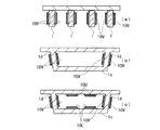
次に、本発明の桁間連結装置10を橋桁断面全体に配置した場合の作用効果について説明する。図9(a)には、橋梁上部工の断面が模式的に示されている。同図に示したように、複数本のプレキャストコンクリート橋桁が図示しない沓座上に設置され、その上に床版が一体的に構築されている。各桁の両側面に本発明の桁間連結装置10Vが取り付けられている。図9(b)は、プレキャストコンクリート橋箱桁1cの断面を模式的に示している。この箱桁1cにおいては、箱桁1cの立壁1dの両面に桁間連結装置10Vが取り付けられている。このように、橋脚上で隣接した梁間での桁間連結装置10Vの設置数に応じて、各装置が負担する伝達応力が異なるため、桁間連結装置10のサイズを適宜設定した経済設計を行うことが好ましい。図9(a),(b)に示した配置構造の場合には、桁に生じる温度差に伴う桁の伸縮方向に対する可動状態を保持できるとともに、桁間での上下方向の応力伝達を確実に行うことができる。   Next, the operation and effect when the inter-girder connecting device 10 of the present invention is arranged over the entire cross section of the bridge girder will be described. FIG. 9A schematically shows a cross section of the bridge superstructure. As shown in the figure, a plurality of precast concrete bridge girders are installed on a scorpion (not shown), and a floor slab is integrally constructed thereon. The inter-girder connecting device 10V of the present invention is attached to both side surfaces of each girder. FIG.9 (b) has shown typically the cross section of the precast concrete bridge box girder 1c. In this box girder 1c, inter-girder connecting devices 10V are attached to both surfaces of the standing wall 1d of the box girder 1c. Thus, since the transmission stress which each apparatus bears differs according to the number of installation of the connecting device 10V between the beams adjacent on the bridge pier, the economical design which set the size of the connecting device 10 appropriately is performed. It is preferable. In the case of the arrangement structure shown in FIGS. 9A and 9B, the movable state with respect to the expansion / contraction direction of the girder due to the temperature difference generated in the girder can be maintained and the vertical stress transmission between the girder can be ensured. It can be carried out.

さらに箱桁構造においては、図9(c)及び図10に示したように、一体構造の箱桁1cの頂版下面と底版上面とに、ケーシング21とラッチプレート11とを、ほぼ水平となるように配置した桁間連結装置10U,10Lを設置することもできる。橋梁上部工において、桁1を橋脚梁部の支承部で支持した場合、図10に示したように、車両通行時に桁1にには許容範囲内での上下振動が生じる。この上下振動に応じて、箱桁の頂版側下面および底面上面に取り付けられた桁間連結装置10U,10Lのラッチプレート11はケーシング21内において、図10に示したように、矢印方向に水平移動する。このときケーシング21内にラッチプレート11を保持するゴム層31に高減衰ゴムを使用することにより、単純桁の上下振動をラッチプレート11のケーシング21内での水平移動に変換させ、この水平移動量を高減衰ゴムで低減し、経時的に減衰させることにより、単純桁の上下振動を減衰させることができる。   Further, in the box girder structure, as shown in FIGS. 9C and 10, the casing 21 and the latch plate 11 are substantially horizontal on the top and bottom plate top surfaces of the integrally structured box girder 1 c. It is also possible to install the interdigit connecting devices 10U and 10L arranged as described above. In the bridge superstructure, when the girder 1 is supported by the support portion of the pier beam part, as shown in FIG. 10, the girder 1 is subject to vertical vibration within an allowable range when the vehicle passes. In response to the vertical vibration, the latch plate 11 of the inter-girder connecting devices 10U and 10L attached to the lower surface of the top plate side and the upper surface of the bottom surface of the box girder is horizontal in the arrow direction in the casing 21 as shown in FIG. Moving. At this time, by using a high damping rubber for the rubber layer 31 that holds the latch plate 11 in the casing 21, the vertical vibration of the simple girder is converted into the horizontal movement in the casing 21 of the latch plate 11, and this horizontal movement amount Can be attenuated with high-damping rubber and attenuated over time, whereby the vertical vibration of a simple girder can be attenuated.

また、桁間連結装置によって橋桁が連結されると、単純桁の場合に比べて、桁の上下方向の固有振動数が高くなる。固有振動数が高いと、同じ減衰の場合でも短時間で振動が低減されるという効果がある。   In addition, when the bridge girder is connected by the inter-girder connecting device, the natural frequency in the vertical direction of the girder becomes higher than in the case of the simple girder. When the natural frequency is high, there is an effect that vibration is reduced in a short time even when the damping is the same.

図11は、桁間連結装置10の製作時の一例を示した説明図である。同図に示したように、桁間連結装置10はあらかじめケーシング21内に、周囲が所定層厚のゴム層31で覆われて収容された状態で製作される。その製作手順として、図11に示したように、ラッチプレート11のケーシング21内に収容される範囲に所定数のスペーサ28を取り付けておき、ラッチプレート11がケーシング21内に挿入された際に、周囲に所定寸法の隙間が形成されるようにしておく。一方、ケーシング21の底面には底板29を仮止めしておく。そしてラッチプレート11を所定深さだけケーシング21内に収容させた後、原料ゴムおよび所定の添加充填剤からなるゴム素材をケーシング21とラッチプレート11の隙間に充填する。さらに原料ゴムの充填されたケーシング21とラッチプレート11とを加硫工程に置き、内部に形成されるゴム層31に所定のゴム弾性性状が得られるように加硫化することが好ましい。ゴム層31がケーシング21内に形成された後に底板29を取り外し、製品を完成させる。以後、ラッチプレート11、ケーシング21とがゴム層を介して一体化された桁間連結装置10を、取り付け現場に搬入して桁1の端部の所定位置に固定ボルト(図示せず)等を介して固定することができる。   FIG. 11 is an explanatory view showing an example when the inter-girder coupling device 10 is manufactured. As shown in the figure, the inter-girder coupling device 10 is manufactured in a state where the periphery is covered and accommodated in advance in a casing 21 with a rubber layer 31 having a predetermined thickness. As a manufacturing procedure thereof, as shown in FIG. 11, a predetermined number of spacers 28 are attached in a range accommodated in the casing 21 of the latch plate 11, and when the latch plate 11 is inserted into the casing 21, A gap having a predetermined dimension is formed around the periphery. On the other hand, a bottom plate 29 is temporarily fixed to the bottom surface of the casing 21. After the latch plate 11 is accommodated in the casing 21 by a predetermined depth, a rubber material made of raw rubber and a predetermined additive filler is filled in the gap between the casing 21 and the latch plate 11. Furthermore, it is preferable to place the casing 21 filled with the raw rubber and the latch plate 11 in a vulcanization step, and vulcanize the rubber layer 31 formed therein so as to obtain a predetermined rubber elasticity. After the rubber layer 31 is formed in the casing 21, the bottom plate 29 is removed to complete the product. Thereafter, the inter-girder coupling device 10 in which the latch plate 11 and the casing 21 are integrated via a rubber layer is carried into the installation site, and a fixing bolt (not shown) or the like is placed at a predetermined position of the end of the girder 1. Can be fixed through.

本発明の桁間連結装置が取り付けられた桁端部が橋脚梁部上で支持された状態を示した概略説明図。BRIEF DESCRIPTION OF THE DRAWINGS Schematic explanatory drawing which showed the state by which the end part of the girder to which the connecting apparatus between girders of this invention was attached was supported on the bridge pier part. 桁側面に取り付けられた桁間連結装置の一実施例を拡大して示した斜視図。The perspective view which expanded and showed one Example of the connection apparatus between the girder attached to the girder side. 図2に示した桁間連結装置の正面図、端面図。The front view and end elevation of the connecting device between girders shown in FIG. 桁間連結装置の他の実施例(補強されたケーシング)を示した斜視図。The perspective view which showed the other Example (reinforced casing) of the connecting apparatus between girders. 桁間連結装置の他の実施例(帯状ラッチ受け部材)を示した斜視図。The perspective view which showed the other Example (strip | belt-shaped latch receiving member) of the inter-girder connection apparatus. 本発明の桁間連結装置が取り付けられた桁端部が橋台上で支持された状態を示した概略説明図。BRIEF DESCRIPTION OF THE DRAWINGS Schematic explanatory drawing which showed the state by which the end part of the girder to which the connecting apparatus for girder of this invention was attached was supported on the abutment. ケーシング内のラッチプレートによる応力集中緩和の各態様を示した部分端面図。The partial end elevation which showed each aspect of the stress concentration relaxation by the latch plate in a casing. 図7のラッチプレートによる応力集中緩和の変形例を示した斜視図、部分端面図。The perspective view and partial end elevation which showed the modification of the stress concentration relaxation by the latch plate of FIG. 各種橋桁断面における桁間連結装置の配置例を示した桁全体断面図。Cross sectional view of the entire girder showing an arrangement example of the connecting device between girder in various cross sections of the bridge girder. 桁床版側に取り付けられた桁間連結装置の作用の一例を示した橋桁支持部全体図。The bridge girder support part whole figure which showed an example of the effect | action of the connection apparatus between the girder attached to the girder slab side. 桁間連結装置の製作時の一態様を示した説明図。Explanatory drawing which showed the one aspect | mode at the time of manufacture of a connection apparatus between girder.

符号の説明Explanation of symbols

1,1A,1B 桁
2 橋脚
10 桁間連結装置
11 ラッチプレート
21 ケーシング
23 隙間
24 開口部
25 補強鋼材
26 ラッチ受け材
31 ゴム層(粘弾性体層)
1, 1A, 1B Girder 2 Bridge pier 10 Girder connecting device 11 Latch plate 21 Casing 23 Gap 24 Opening 25 Reinforced steel material 26 Latch receiving material 31 Rubber layer (viscoelastic material layer)

Claims (6)

支承上に隣接して支持された橋桁の一方の桁端部に取り付けられ、かんぬきとしての機能を奏するプレートと、かんぬき受けとして、前記プレートの一部を、その内部に挿入して保持する、他方の桁端部に取り付けられたプレート受け部とを備えた桁間連結装置であって、前記プレート受け部内に挿入されたプレートの全周が粘弾性体層を介して前記プレート受け部に保持されたことを特徴とする桁間連結装置。 A plate that is attached to one girder end of a bridge girder supported adjacently on the bearing and that functions as a hammer, and a part of the plate is inserted into and held as a hammer receiver , and the other of a digit between coupling device and a Plate receiving portion attached to girder end, before the entire circumference of the inserted Plate previously Kipu rate receiving portion via the viscoelastic material layer Kipu An interdigit connecting device, which is held in a rate receiving portion. 記プレート受け部は、前記プレートの先端側全体を内部に収容し保持する扁平箱状ケーシングである請求項1に記載の桁間連結装置。 Before Kipu rate receiving unit, front spar linkage apparatus of claim 1 tip side entire Kipu rate is flat box-shaped casing which houses therein retained. 記プレート受け部は、前記プレートの中間部位をフランジ部で保持する帯板状部材である請求項1に記載の桁間連結装置。 Before Kipu rate receiving unit, interdigit coupling device according to the intermediate portion of the front Kipu rate to claim 1 which is a band plate-like member held by the flange portion. 前記粘弾性体層は、前記プレートと前記プレート受け部の隙間に充填され形成されたゴム層であることを特徴とする請求項1乃至請求項3のいずれか1項に記載の桁間連結装置。 The viscoelastic layer digits according to any one of claims 1 to 3, characterized in that before a Kipu rate and rubber layer filled formed in the gap of the Plate receiving portion Inter-connection device. 記プレートは、上下端部が面取りされ、前記粘弾性体層に対しての応力集中を緩和させた請求項1乃至請求項3のいずれか1項に記載の桁間連結装置。 Before Kipu rate, upper and lower ends are chamfered, interdigit coupling device according to any one of claims 1 to 3 stress concentration was alleviated in respect to the viscoelastic layer. 前記ケーシングは、内周隅部が面当てされ、前記粘弾性体層に対しての応力集中を緩和させた請求項に記載の桁間連結装置。 The inter-girder connection device according to claim 2 , wherein the casing has an inner peripheral corner faced to reduce stress concentration on the viscoelastic body layer.
JP2007102580A 2007-04-10 2007-04-10 Interdigit connection device Expired - Fee Related JP4858848B2 (en)

Priority Applications (1)

Application Number Priority Date Filing Date Title
JP2007102580A JP4858848B2 (en) 2007-04-10 2007-04-10 Interdigit connection device

Applications Claiming Priority (1)

Application Number Priority Date Filing Date Title
JP2007102580A JP4858848B2 (en) 2007-04-10 2007-04-10 Interdigit connection device

Publications (2)

Publication Number Publication Date
JP2008261099A JP2008261099A (en) 2008-10-30
JP4858848B2 true JP4858848B2 (en) 2012-01-18

Family

ID=39983779

Family Applications (1)

Application Number Title Priority Date Filing Date
JP2007102580A Expired - Fee Related JP4858848B2 (en) 2007-04-10 2007-04-10 Interdigit connection device

Country Status (1)

Country Link
JP (1) JP4858848B2 (en)

Families Citing this family (2)

* Cited by examiner, † Cited by third party
Publication number Priority date Publication date Assignee Title
JP5469734B1 (en) * 2012-11-29 2014-04-16 日本車輌製造株式会社 Bridge control system
KR101622626B1 (en) * 2013-12-13 2016-05-20 (주)태인이앤씨 Earthquake resistant reinforcement apparatus for bridge

Family Cites Families (17)

* Cited by examiner, † Cited by third party
Publication number Priority date Publication date Assignee Title
JPS53223B2 (en) * 1973-07-23 1978-01-06
US4341512A (en) * 1980-07-31 1982-07-27 Hauck Manufacturing Company Burner
JPS5733706A (en) * 1980-08-04 1982-02-23 Vnii Tekunishiesukogo Ugurerod Fuel atmizer
CA1206981A (en) * 1983-01-17 1986-07-02 Edward R. Fyfe Deflection control device
JPH0197766A (en) * 1987-10-07 1989-04-17 Sumitomo Constr Co Ltd Manufacture of earthquake-control wall
JPH01119411A (en) * 1987-10-31 1989-05-11 Isuzu Motors Ltd Energizing control device for glow plug
JP2612414B2 (en) * 1993-12-27 1997-05-21 株式会社日本アルミ Light bridge
JP3321694B2 (en) * 1995-08-24 2002-09-03 大成ロテック株式会社 Repair / reinforcement method of reinforced concrete slab upper surface
JPH11230253A (en) * 1998-02-18 1999-08-27 Taisei Corp Damper
JP2001115416A (en) * 1999-10-18 2001-04-24 Sekisui Chem Co Ltd Connection structure of floating body for floating pier
JP2001207412A (en) * 2000-01-28 2001-08-03 Tokai Rubber Ind Ltd Rubber support body
JP2002129520A (en) * 2000-10-26 2002-05-09 Railway Technical Res Inst Preventive device for bridge fall
JP3862529B2 (en) * 2001-08-17 2006-12-27 株式会社神戸製鋼所 Damping bridge
JP3812427B2 (en) * 2001-11-27 2006-08-23 株式会社住軽日軽エンジニアリング Suspension scaffold for bridge inspection
JP2005233367A (en) * 2004-02-23 2005-09-02 Kawaguchi Metal Industries Co Ltd Connection member of structure
JP2005331035A (en) * 2004-05-19 2005-12-02 Sumitomo Mitsui Construction Co Ltd Seismic response control device
JP2006349064A (en) * 2005-06-16 2006-12-28 Tokai Rubber Ind Ltd Vibration control device and its manufacturing method

Also Published As

Publication number Publication date
JP2008261099A (en) 2008-10-30

Similar Documents

Publication Publication Date Title
CN106368115B (en) A kind of shock isolation system suitable for medium and small span beam bridge
JP5539554B1 (en) Girder bridge connection structure and girder bridge structure
JP4858848B2 (en) Interdigit connection device
JP2008038504A (en) Method for improving antiseismic performance of bridge
JP5164234B2 (en) Expansion joint for bridge
KR101781544B1 (en) Rahmem bridge of seismic performanceusing prestressed using crossbeam
JP3869236B2 (en) Seismic reinforcement method for existing reinforced concrete viaduct
JP6642884B2 (en) Bridge steel deck slab reinforcement structure and bridge steel deck slab reinforcement method
CN108643028B (en) Bridge girder body anti-deviation device with pier protection function
Javanmardi et al. Seismic pounding mitigation of an existing cable-stayed bridge using metallic dampers
JP2006266011A (en) Jointing structure of ecological floor slab, and its construction method
JP5111194B2 (en) Telescopic device for bridge and telescopic structure for bridge
JP2909066B1 (en) Repair method of existing bridge bearing device
KR100622008B1 (en) Composition structure of integral abutment bridge
KR101905886B1 (en) Rahmem bridge of seismic performance and bibration attenuating performance using prestressed using crossbeam
JP2004316170A (en) Expansive coupling device for bridge
KR101409400B1 (en) Laminated rubber bearing having hat-shaped steel damper
Tandon Economical design of earthquake-resistant bridges
JP5457997B2 (en) Telescopic device for bridge
JP5120676B2 (en) Interdigit connection device
KR100313031B1 (en) The temporary fixing device &method of L.R.B(Lead Rubber Bearing) in I.L.M(Incremental Launching method) bridge
JP3210126U (en) Bridge type expansion joint structure for bridges
JP2009068295A (en) Elevated structure
JP4076185B2 (en) How to design an extended floor slab
JP5706952B1 (en) Bridge structure and existing bridge reinforcement method

Legal Events

Date Code Title Description
A621 Written request for application examination

Free format text: JAPANESE INTERMEDIATE CODE: A621

Effective date: 20091225

A977 Report on retrieval

Free format text: JAPANESE INTERMEDIATE CODE: A971007

Effective date: 20110525

A131 Notification of reasons for refusal

Free format text: JAPANESE INTERMEDIATE CODE: A131

Effective date: 20110614

A521 Written amendment

Free format text: JAPANESE INTERMEDIATE CODE: A523

Effective date: 20110810

TRDD Decision of grant or rejection written
A01 Written decision to grant a patent or to grant a registration (utility model)

Free format text: JAPANESE INTERMEDIATE CODE: A01

Effective date: 20110927

A01 Written decision to grant a patent or to grant a registration (utility model)

Free format text: JAPANESE INTERMEDIATE CODE: A01

A61 First payment of annual fees (during grant procedure)

Free format text: JAPANESE INTERMEDIATE CODE: A61

Effective date: 20111020

R150 Certificate of patent or registration of utility model

Ref document number: 4858848

Country of ref document: JP

Free format text: JAPANESE INTERMEDIATE CODE: R150

Free format text: JAPANESE INTERMEDIATE CODE: R150

FPAY Renewal fee payment (event date is renewal date of database)

Free format text: PAYMENT UNTIL: 20141111

Year of fee payment: 3

LAPS Cancellation because of no payment of annual fees