JP4838331B2 - Microscope illumination device - Google Patents
Microscope illumination device Download PDFInfo
- Publication number
- JP4838331B2 JP4838331B2 JP2009088763A JP2009088763A JP4838331B2 JP 4838331 B2 JP4838331 B2 JP 4838331B2 JP 2009088763 A JP2009088763 A JP 2009088763A JP 2009088763 A JP2009088763 A JP 2009088763A JP 4838331 B2 JP4838331 B2 JP 4838331B2
- Authority
- JP
- Japan
- Prior art keywords
- illumination
- observation
- microscope
- deflecting
- deflection
- Prior art date
- Legal status (The legal status is an assumption and is not a legal conclusion. Google has not performed a legal analysis and makes no representation as to the accuracy of the status listed.)
- Expired - Fee Related
Links
Images


Classifications
-
- G—PHYSICS
- G02—OPTICS
- G02B—OPTICAL ELEMENTS, SYSTEMS OR APPARATUS
- G02B27/00—Optical systems or apparatus not provided for by any of the groups G02B1/00 - G02B26/00, G02B30/00
- G02B27/10—Beam splitting or combining systems
- G02B27/14—Beam splitting or combining systems operating by reflection only
- G02B27/144—Beam splitting or combining systems operating by reflection only using partially transparent surfaces without spectral selectivity
-
- A—HUMAN NECESSITIES
- A61—MEDICAL OR VETERINARY SCIENCE; HYGIENE
- A61B—DIAGNOSIS; SURGERY; IDENTIFICATION
- A61B3/00—Apparatus for testing the eyes; Instruments for examining the eyes
- A61B3/10—Objective types, i.e. instruments for examining the eyes independent of the patients' perceptions or reactions
- A61B3/13—Ophthalmic microscopes
- A61B3/132—Ophthalmic microscopes in binocular arrangement
-
- G—PHYSICS
- G02—OPTICS
- G02B—OPTICAL ELEMENTS, SYSTEMS OR APPARATUS
- G02B21/00—Microscopes
- G02B21/06—Means for illuminating specimens
- G02B21/08—Condensers
-
- G—PHYSICS
- G02—OPTICS
- G02B—OPTICAL ELEMENTS, SYSTEMS OR APPARATUS
- G02B27/00—Optical systems or apparatus not provided for by any of the groups G02B1/00 - G02B26/00, G02B30/00
- G02B27/10—Beam splitting or combining systems
- G02B27/14—Beam splitting or combining systems operating by reflection only
- G02B27/143—Beam splitting or combining systems operating by reflection only using macroscopically faceted or segmented reflective surfaces
-
- G—PHYSICS
- G02—OPTICS
- G02B—OPTICAL ELEMENTS, SYSTEMS OR APPARATUS
- G02B27/00—Optical systems or apparatus not provided for by any of the groups G02B1/00 - G02B26/00, G02B30/00
- G02B27/10—Beam splitting or combining systems
- G02B27/14—Beam splitting or combining systems operating by reflection only
- G02B27/145—Beam splitting or combining systems operating by reflection only having sequential partially reflecting surfaces
Description
本発明は、とりわけ手術顕微鏡等の顕微鏡の照明装置に関する。本発明は、特に、照明システムと、該照明システムから射出される光ビームをとりわけ被手術眼等の観察対象へ向けて偏向するための偏向装置とを有すると共に、該偏向装置が、少なくとも1つの観察光路に関し異なる複数の照明角度により前記観察対象の照明を許容する形式の、少なくとも1つの観察光路を有するとりわけ手術顕微鏡等の顕微鏡のための照明装置に関する。
更に、本発明は、上記照明装置を有するとりわけステレオ顕微鏡等の顕微鏡に関する。
The present invention relates to an illumination device for a microscope such as a surgical microscope. The invention particularly comprises an illumination system and a deflection device for deflecting a light beam emitted from the illumination system, in particular towards an observation object such as a surgical eye, wherein the deflection device comprises at least one The present invention relates to an illumination device for a microscope, in particular, a surgical microscope or the like, having at least one observation light path, which allows illumination of the observation object with a plurality of different illumination angles with respect to the observation light path.
Furthermore, this invention relates to microscopes, such as a stereomicroscope, which have the said illuminating device.
手術顕微鏡用の照明装置は、通常、観察光路(その光軸)に関し凡そ6°の範囲のある所定の角度をなす1つの照明光路(所謂6°照明)を使用する。このため、観察光路と照明光路との間の角度をより大きくした場合に生じ得る望ましくない影が生じることは回避されてはいる。 An illumination device for a surgical microscope normally uses one illumination light path (so-called 6 ° illumination) that forms a predetermined angle with a range of approximately 6 ° with respect to the observation light path (its optical axis). For this reason, the occurrence of undesirable shadows that can occur when the angle between the observation optical path and the illumination optical path is made larger is avoided.
眼科手術の場合には、顕微鏡の照明に関し更に特別な要求が幾つかある。まず、この場合も凡そ6°の照明角度で画像の十分なフレキシビリティないし可塑性(柔軟性、適応性、再現性:Plastizitaet)を維持することである。しかしながら、所定の眼科外科処置上の観察又は手術には、所謂赤色反射を生成することが不可避である。この赤色反射ため、被手術眼の瞳は、網膜によって反射・散乱された戻り光によって赤く光る。このような照明の性質は、例えば白内障手術の場合には極めて重要である。というのは、手術の際に、組織の残留物は、赤色反射の戻り光中においてとりわけ良好に認識(検出)可能であるべきだからである。赤色反射を生成するには、観察光路(その光軸に関し)と照明光路との間の角度をより小さくする必要があり、その角度は、0°〜2°の範囲にあることが好ましい(所謂2°照明)。 In the case of ophthalmic surgery, there are some additional special requirements regarding the illumination of the microscope. First, in this case as well, sufficient flexibility or plasticity (flexibility, adaptability, reproducibility: Plastizitaet) of the image is maintained at an illumination angle of about 6 °. However, it is inevitable to produce a so-called red reflex for observation or surgery on a given ophthalmic surgical procedure. Due to this red reflection, the pupil of the eye to be operated shines red due to the return light reflected and scattered by the retina. Such illumination properties are extremely important, for example, in the case of cataract surgery. This is because during surgery, tissue residues should be particularly well recognizable (detectable) in the red reflected return light. In order to generate red reflection, it is necessary to make the angle between the observation optical path (with respect to its optical axis) and the illumination optical path smaller, and the angle is preferably in the range of 0 ° to 2 ° (so-called so-called). 2 ° illumination).
手術者(主観察者)と助手(副観察者)のための2対のステレオ観察光路を有する手術顕微鏡では、主観察者は赤色反射を非常に良好に観察することができるが、副観察者は赤色反射を不十分にしか観察することができないという欠点が生じることがしばしばある。副観察者は、その位置に応じ、主観察者の右側又は左側で、自分の2つの観察チャンネルの内の一方のみにおいて良好な赤色反射を観察する。このため、立体的な観察は阻害される。 In a surgical microscope having two pairs of stereo observation light paths for an operator (main observer) and an assistant (sub observer), the main observer can observe the red reflection very well. Often has the disadvantage that red reflections can only be observed inadequately. The sub-observer observes a good red reflection in only one of his two observation channels on the right or left side of the main observer, depending on the position. For this reason, three-dimensional observation is inhibited.
顕微鏡対物レンズの主光軸の外部に(から外れて)配置され、かつ顕微鏡対物レンズを介して対物レンズ主光軸に対し平行に手術領域を照明する照明システムと、顕微鏡対物レンズの観察対象を指向する面と反対側の面側に配され、かつ照明光の一部を対物レンズ主光軸に沿って手術領域へと向かわせる1つの偏向要素とを有する形式の手術顕微鏡用の照明装置について記載している文献がある(特許文献1参照)。この照明装置では、照明システムは、照明光を対物レンズ主光軸に対し平行に顕微鏡対物レンズに向かって反射する反射要素を対物レンズ側に有し、及び偏向要素は、顕微鏡主光軸に対しある所定の傾斜角度(その大きさは、反射要素が手術領域を照明する際の傾斜角度の大きさより小さい)で手術領域を照明する。この照明装置では、(反射要素による)より大きい方の傾斜角度は6°が好ましいとされ、(偏向要素による)より小さいほうの傾斜角度は0°〜6°の間で調節可能とされている。しかしながら、この照明装置には以下のような欠点がある:偏向要素によって反射される光ビームは、照明システムの照明瞳の周辺光線であるため、例えば観察光路に対し2°の角度で照明を行う近軸照明の場合、観察領域の照明は比較的不均一でけられも生じ得る。 An illumination system that illuminates the surgical area parallel to the main optical axis of the objective lens via the microscope objective lens and the observation target of the microscope objective lens is arranged outside (distant from) the main optical axis of the microscope objective lens. An illuminating device for a surgical microscope of a type having a single deflecting element that is arranged on the surface opposite to the surface to be directed and that directs a part of the illumination light to the surgical region along the main optical axis of the objective lens There is a document described (see Patent Document 1). In this illuminating device, the illumination system has a reflection element on the objective lens side that reflects the illumination light toward the microscope objective lens in parallel to the objective lens main optical axis, and the deflection element is relative to the microscope main optical axis. The surgical field is illuminated at a certain predetermined tilt angle (the magnitude of which is smaller than the tilt angle when the reflective element illuminates the surgical field). In this lighting device, the larger inclination angle (due to the reflecting element) is preferably 6 °, and the smaller inclination angle (due to the deflecting element) is adjustable between 0 ° and 6 °. . However, this illumination device has the following disadvantages: the light beam reflected by the deflecting element is a peripheral ray of the illumination pupil of the illumination system and therefore illuminates, for example, at an angle of 2 ° with respect to the observation light path In the case of paraxial illumination, the illumination in the observation area is relatively non-uniform and can occur.
他にも、手術顕微鏡用の照明装置について記載している文献は幾つかある(特許文献2及び3参照)。これらの照明装置も、同様に、近軸照明のために、照明装置の照明瞳の周辺光線を使用するため、上述の欠点も同様に生じてしまう。 In addition, there are several documents describing illumination devices for surgical microscopes (see Patent Documents 2 and 3). Since these illumination devices also use the peripheral rays of the illumination pupil of the illumination device for paraxial illumination, the above-mentioned drawbacks also occur.
上記各特許文献に記載された照明装置には、それらが適用される手術顕微鏡は、高さ方向に互いに離隔した(ずらされた)位置から(ないし当該位置に配された要素を介して)2°照明及び6°照明が行われるため、その構造高さが比較的大きくなってしまうという更なる欠点もある。 In the illumination devices described in each of the above patent documents, the surgical microscope to which they are applied is from a position (or through an element disposed at the position) 2 spaced (shifted) from each other in the height direction. Since the ° illumination and the 6 ° illumination are performed, there is a further disadvantage that the structural height becomes relatively large.
それゆえ、本発明の課題は、従来の同様の装置と比べて、照明領域をより一様にかつよりけられが少なく隈なく(完全に)照明することが可能な顕微鏡用の照明装置を提供することである。これと同時に、照明装置をできるだけコンパクトに構成して、顕微鏡の構造高さを望ましくない態様で大きくしてしまわないことも本発明の一つの課題をなす。更に、上記の照明装置を有する顕微鏡を提供することも本発明の一つ課題をなす。 Therefore, an object of the present invention is to provide an illumination device for a microscope that can illuminate an illumination region more uniformly and less easily (completely) than a conventional similar device. It is to be. At the same time, it is an object of the present invention to make the illumination device as compact as possible so as not to increase the structural height of the microscope in an undesirable manner. It is another object of the present invention to provide a microscope having the above illumination device.
本発明の第1の視点により、少なくとも1つの観察光路を有するとりわけ手術顕微鏡等の顕微鏡のための照明装置であって、照明システムと、該照明システムから射出される光ビームをとりわけ被手術眼等の観察対象へ向けて偏向するための偏向装置とを有すると共に、該偏向装置が、前記少なくとも1つの観察光路に関し異なる(複数の)照明角度により前記観察対象の照明を許容するよう構成された照明装置が提供される。この照明装置において、前記偏向装置は、少なくとも部分的(局所的)に物理的ビームスプリッタとして構成されかつ唯一の光軸に沿って配された2つの偏向要素を有することを特徴とする(形態1・基本構成1)。ここに、前記2つの偏向要素の少なくとも1つは、部分的に完全反射性に構成され、前記偏向装置は、一体のプリズムブロックとして構成されるか、又は、空間的に互いに分離する2つのプリズムブロックから構成される。
更に、本発明の第2の視点により、少なくとも1つの観察光路を有する顕微鏡のための照明装置であって、照明システムと、該照明システムから射出される光ビームを観察対象へ向けて偏向するための偏向装置とを有すると共に、該偏向装置が、前記少なくとも1つの観察光路に関し異なる複数の照明角度により前記観察対象の照明を許容するよう構成された照明装置が提供される。この照明装置において、前記偏向装置は、前記観察対象に対する+2°照明及び−2°照明を同時に実行可能にすると共に唯一の光軸に沿って配された2つの偏向要素を有することを特徴とする(形態4・基本構成2)。ここに、前記2つの偏向要素の少なくとも1つは、部分的に完全反射性に構成され、前記偏向装置は、一体のプリズムブロックとして構成されるか、又は、空間的に互いに分離する2つのプリズムブロックから構成される。
更に、本発明の第3の視点により、主対物レンズと、該主対物レンズに後置される拡大システム(変倍系)と、形態1〜形態8の何れか1つの照明装置とを有する、とりわけステレオ顕微鏡等の顕微鏡が提供される(形態9・基本構成3)。
更に、本発明の第4の視点により、照明システムと、該照明システムから射出される光ビームをとりわけ被手術眼等の観察対象へ向けて偏向するための偏向装置とを有すると共に、該偏向装置が、少なくとも1つの観察光路に関し異なる複数の照明角度により前記観察対象の照明を許容するよう構成された照明装置を有し、前記偏向装置が、少なくとも部分的に物理的ビームスプリッタとして構成されかつ唯一の光軸に沿って配された2つの偏向要素と、を有する形式の、とりわけステレオ顕微鏡等の顕微鏡が提供される。この顕微鏡は、顕微鏡の複数の観察チャンネルに挿入可能な少なくとも1つのブロック状ガラス部材を有することを特徴とする(形態14・基本構成4)。ここに、ブロック状ガラス部材は、観察チャネルに対し透過性であり、かつ観察チャネルの瞳の狭窄を実現可能にする。
According to a first aspect of the present invention, there is provided an illumination device for a microscope, particularly a surgical microscope, having at least one observation optical path, the illumination system and a light beam emitted from the illumination system, in particular, a surgical eye, etc. And a deflection device for deflecting toward the observation object, the deflection device configured to allow illumination of the observation object at different illumination angles with respect to the at least one observation light path An apparatus is provided. In this illuminating device, the deflecting device has two deflecting elements which are at least partially (locally) configured as a physical beam splitter and arranged along a single optical axis (form 1) -Basic configuration 1). Here, at least one of the two deflection elements is configured to be partially fully reflective, and the deflection device is configured as an integral prism block, or two prisms that are spatially separated from each other. Consists of blocks.
Further, according to the second aspect of the present invention, there is provided an illumination device for a microscope having at least one observation optical path, for deflecting an illumination system and a light beam emitted from the illumination system toward an observation object. And an illuminating device configured to allow illumination of the observation object at a plurality of different illumination angles with respect to the at least one observation optical path. In this illuminating device, the deflecting device can perform + 2 ° illumination and −2 ° illumination on the observation object at the same time, and has two deflecting elements arranged along a single optical axis. (
Furthermore, according to a third aspect of the present invention, the optical system includes a main objective lens, an enlargement system (magnification system) placed behind the main objective lens, and the illumination device according to any one of
Furthermore, according to a fourth aspect of the present invention, there is provided an illumination system, and a deflection device for deflecting a light beam emitted from the illumination system toward an observation target such as an eye to be operated, and the deflection device. Comprises an illuminating device configured to allow illumination of the object to be observed with a plurality of different illumination angles with respect to at least one observation optical path, wherein the deflecting device is at least partly configured as a physical beam splitter and only There is provided a microscope, in particular a stereo microscope, of the type having two deflection elements arranged along the optical axis . This microscope has at least one block-shaped glass member that can be inserted into a plurality of observation channels of the microscope (
本発明の各独立請求項により、所定の課題として掲げた効果が、上述の通りそれぞれ達成される。即ち、本発明の照明装置は、従来の同様の装置と比べて、照明領域をより一様にかつよりけられが少なく隈なく(完全に)照明することが可能であると同時に、適用される顕微鏡の構造高さを望ましくない態様で大きくしてしまわないように可及的にコンパクトに構成されうる(基本構成1及び2)。このような顕微鏡の照明領域の一様かつけられのない隈なき(完全な)照明は、(照明光を照明システムから観察対象へ向けて偏向する)物理的ビームスプリッタとして構成される複数の偏向要素を使用することにより、照明瞳のほぼ完全な横断面が、複数の偏向要素ないし複数のミラー要素の有効面積の全体に亘って(併せて)貫通ないし反射して有効利用することによって保証される。これに対し、従来の照明装置では、偏向要素(の面の内)の完全反射性の小部分のみを使用して、照明瞳の周辺領域を偏向して利用していたにすぎないのである。即ち、従来技術のビームスプリッタは、(複数の異なった角度での傾斜照明を形成するために、照明光線束を幾何学的ないし空間的に分割する)幾何学的ないし空間的ビームスプリッタであるということができる(従って、複数の偏向要素を高さ方向にずらして配さざるを得ない)。これに対し、本発明の偏向装置では、複数の偏向要素がすべてただ1つの光軸に配されるため、照明装置の、延いては顕微鏡の構造高さを有利に小さくすることができる。
また、本発明の顕微鏡は、従来の同様の顕微鏡と比べて、その照明領域がより一様にかつよりけられが少なく隈なく照明することが可能であると同時に、その構造高さもより小さく構成することが可能である(基本構成3及び4)。
更に、各従属請求項により、付加的な効果が後述の通りそれぞれ達成される。
According to the independent claims of the present invention, the effects listed as the predetermined problems can be achieved as described above. That is, the illumination device of the present invention can be applied at the same time as it can illuminate the illumination area more uniformly and less easily (completely) than the conventional similar device. It can be configured as compact as possible so as not to increase the structural height of the microscope in an undesired manner (
In addition, the microscope of the present invention can be illuminated with a uniform illumination area, less squeezing and less, and at the same time having a smaller structural height than a conventional similar microscope. (
Furthermore, according to the dependent claims, additional effects are achieved respectively as described below.
以下に、本発明の好ましい実施の形態を示すが、これらは従属請求項の対象でもある。(なお、形態1、4、9、14は既述のとおり)
(2) 上記形態1の照明装置において、前記偏向装置は、唯一の光軸に沿って配された3つの偏向要素を有することが好ましい(形態2)。
(3) 上記形態1又は2の照明装置において、前記観察対象に対し+2°照明及び−2°照明を同時に実行可能なように、2つの偏向要素が構成されることが好ましい(形態3)。
(5) 上記形態1〜4の何れか1つの照明装置において、前記偏向要素の少なくとも1つは、少なくとも部分的(局所的)に完全反射性に(完全鍍銀化(完全ミラー化)されるよう)構成されることが好ましい(形態5)。
(6) 上記形態1〜5の何れか1つの照明装置において、前記偏向装置は、部分反射性の複数の面を有するプリズム複合システム(複数のプリズムの組合せ)として構成されることが好ましい(形態6)。
(7) 上記形態1〜6の何れか1つの照明装置において、前記偏向装置は、一体のプリズムブロックとして構成されることが好ましい(形態7)。
(8) 上記形態1〜6の何れか1つの照明装置において、前記偏向装置は、空間的に互いに分離する2つのプリズムブロックから構成されることが好ましい(形態8)。
(10) 上記形態9の顕微鏡は、4つの観察チャンネルを有することが好ましい(形態10)。
(11) 上記形態9又は10の顕微鏡は、照明ビーム路を選択的にオン・オフ(遮断・導通)切換するための複数のシャッタを有することが好ましい(形態11)。
(12) 上記形態9〜11の何れか1つの顕微鏡において、前記偏向装置は、主対物レンズと拡大システムとの相対的な位置関係によって規定される顕微鏡の光軸に関し、横断的に摺動可能に構成されることが好ましい(形態12)。
(13) 上記形態10〜12の何れか1つの顕微鏡は、前記4つの観察チャンネルに挿入可能な複数のブロック状ガラス部材を有することが好ましい(形態13)。
(15) 上記形態14の顕微鏡において、前記少なくとも1つのブロック状ガラス部材は、前記偏向装置と接合されていることが好ましい(形態15)。
In the following, preferred embodiments of the invention are shown, which are also the subject of the dependent claims. (Note that
(2) In the illuminating device according to the first aspect, it is preferable that the deflecting device has three deflecting elements arranged along a single optical axis (second form).
(3) In the illuminating device according to the first aspect or the second aspect, it is preferable that two deflecting elements are configured so that + 2 ° illumination and −2 ° illumination can be simultaneously performed on the observation target (mode 3).
(5) In the illumination device according to any one of the first to fourth aspects, at least one of the deflection elements is at least partially (locally) fully reflective (completely silvered (completely mirrored)). It is preferable to be configured (form 5).
(6) In the illumination device according to any one of the first to fifth aspects, the deflecting device is preferably configured as a prism composite system (a combination of a plurality of prisms) having a plurality of partially reflective surfaces. 6).
(7) In any one of the lighting devices according to the first to sixth embodiments, it is preferable that the deflecting device is configured as an integral prism block (aspect 7).
(8) In any one of the illuminating devices according to the first to sixth aspects, it is preferable that the deflecting device includes two prism blocks that are spatially separated from each other (mode 8).
(10) It is preferable that the microscope of the said form 9 has four observation channels (form 10).
(11) It is preferable that the microscope according to the ninth or tenth aspect includes a plurality of shutters for selectively switching on / off (blocking / conducting) the illumination beam path (mode 11).
(12) In the microscope according to any one of the above embodiments 9 to 11, the deflecting device can slide across the optical axis of the microscope defined by the relative positional relationship between the main objective lens and the magnifying system. (Form 12)
(13) It is preferable that any one of the above-described forms 10 to 12 has a plurality of block-shaped glass members that can be inserted into the four observation channels (form 13).
(15) In the microscope according to the fourteenth aspect, it is preferable that the at least one block-shaped glass member is bonded to the deflecting device (mode 15).
本発明の照明装置の好ましい一実施形態によれば、偏向装置は、少なくとも3つの偏向要素を有する。3つの偏向要素を有するよう構成されるこの実施形態では、例えば手術顕微鏡において、6°照明、+2°照明及び−2°照明を行うことができる。 According to a preferred embodiment of the illumination device of the invention, the deflection device has at least three deflection elements. In this embodiment configured to have three deflection elements, 6 ° illumination, + 2 ° illumination and −2 ° illumination can be performed, for example, in a surgical microscope.
本発明のとりわけ好ましい一実施形態では、2つの偏向要素が、少なくとも部分的(局所的)に物理的ビームスプリッタとして構成されるか否かにかかわらず、+2°照明及び−2°照明を同時に行うことができるよう構成される。この照明態様は、とりわけ眼球の回転(Verrollung)が生じ得る場合の赤色反射を利用する手術技術に対し有利であることが分かる。そのような手術技術の例として、水晶体超音波吸引術が考えられる。+2°及び−2°の同時照明により、手術者がその作業中に顕微鏡の調節状態を変化する必要がなくなることが保証される。+2°、−2°及び6°の同時照明も実行可能であり、更には、これらの角度のその他の任意の組合せ(これは、例えば相応の配置を取りうる複数の絞りを使用することにより実現可能である)による(同時)照明も実行可能である。 In a particularly preferred embodiment of the invention, + 2 ° illumination and -2 ° illumination are performed simultaneously, regardless of whether the two deflection elements are at least partially (locally) configured as physical beam splitters. Configured to be able to. This illumination aspect proves to be particularly advantageous for surgical techniques that utilize red reflections where eyeball rotation can occur. As an example of such a surgical technique, phacoemulsification is conceivable. Simultaneous + 2 ° and -2 ° illumination ensures that the operator does not need to change the microscope's adjustment state during the operation. Simultaneous illumination of + 2 °, -2 ° and 6 ° is also feasible, as well as any other combination of these angles (this is achieved for example by using multiple stops which can take corresponding arrangements) (Simultaneous) lighting is also feasible.
複数の偏向要素のうちの少なくとも1つが、少なくとも部分的(局所的)に完全反射性に構成される(完全鍍銀化(完全ミラー化)される)と好都合である。この形態によって、完全反射性領域に入射した光は、完全に、観察対象に向かって偏向されるため、照明強度(明るさ)に関し有利に影響しうる。更に、この形態により、顕微鏡の観察光路と完全反射性領域との間の重なり(重ね合わせ)を簡単な態様で形成することができる。このような重なりは、眼科外科の分野における所定の措置に対して、例えば赤色反射の生成ないし調節のために必要である。 Conveniently, at least one of the plurality of deflecting elements is at least partially (locally) fully configured (completely silvered (completely mirrored)). With this configuration, the light incident on the completely reflective region is completely deflected toward the object to be observed, which can advantageously affect the illumination intensity (brightness). Furthermore, with this configuration, it is possible to form an overlap (overlap) between the observation optical path of the microscope and the completely reflective region in a simple manner. Such an overlap is necessary for certain procedures in the field of ophthalmic surgery, for example for the generation or adjustment of red reflexes.
本発明の照明装置のとりわけ好ましい一実施形態では、偏向装置が、部分反射性の複数の面を有するプリズム複合システム(複数のプリズムの組合せ)として構成される。プリズムシステムは、実用上、比較的少ない労力で調節できるため有利である。尤も、偏向装置を相応に位置調節可能な複数の部分反射性ミラーによって構成することも可能である。 In a particularly preferred embodiment of the illumination device according to the invention, the deflection device is configured as a prism composite system (combination of a plurality of prisms) having a plurality of partially reflective surfaces. The prism system is advantageous because it can be practically adjusted with relatively little effort. However, it is also possible to configure the deflecting device by a plurality of partially reflective mirrors whose positions can be adjusted accordingly.
本発明のとりわけ好ましい一実施形態では、偏向装置は、一体ないし一部材(ワンピース)のプリズムブロックとして構成される。このような一体のプリズムブロックでは、顕微鏡の組み立て(製造)の際に必要な調節作業は、最少に留めることができる。更に、このようなプリズムブロックは、顕微鏡の作動時には、極めて頑強である(例えば、作動時の振動等により作用面間の相対的位置関係がずれない)ため有利である。 In a particularly preferred embodiment of the invention, the deflection device is configured as a single or one-piece prism block. With such an integral prism block, the adjustment work required for assembling (manufacturing) the microscope can be minimized. Furthermore, such a prism block is advantageous because it is extremely robust when the microscope is operated (for example, the relative positional relationship between the working surfaces does not shift due to vibration during operation).
また、偏向装置は、空間的に互いに分離した2つのプリズムブロックを有することも可能である。この形態では、例えば、観察光路を阻害するような偏向装置の個々のプリズム間の接合部(これによって像が二重になったり反射が生じたりしうる)を実質的に回避することができる。ここで、偏向要素(複数)は、プリズムブロック(複数)から独立して位置決めされる相応の反射性及び/又は透過性ミラーとして構成することも可能であることに注意すべきである。 The deflecting device can also have two prism blocks spatially separated from each other. In this embodiment, for example, a joint between individual prisms of the deflecting device that obstructs the observation optical path (which may cause a double image or reflection) can be substantially avoided. It should be noted here that the deflection element (s) can also be configured as a corresponding reflective and / or transmissive mirror that is positioned independently of the prism block (s).
本発明の顕微鏡の好ましい一実施形態では、顕微鏡は、ステレオ(立体)顕微鏡として構成される。この形態では、ステレオ顕微鏡は、主観察者のための2つの観察光路(観察チャンネル)と、副観察者のための更なる2つの観察光路(観察チャンネル)を有するととりわけ好ましい。とりわけこのような主観察者及び副観察者のための複数の観察光路を有するステレオ顕微鏡では、この種の従来の顕微鏡とは異なり、主観察者にも、副観察者にも、赤色反射の特性を所望の態様で調節することができる。照明瞳のほぼ全域を使用できるため、けられ(口径食)を大幅に阻止することができ、主観察者に対しても、副観察者に対しても、一様(均一)な照明領域を供給することができる。 In a preferred embodiment of the microscope of the present invention, the microscope is configured as a stereo (stereoscopic) microscope. In this form, it is particularly preferred that the stereo microscope has two observation light paths (observation channels) for the main observer and two further observation light paths (observation channels) for the secondary observer. In particular, a stereo microscope having a plurality of observation light paths for the main observer and the sub-observer is different from the conventional microscope of this type in that the characteristics of red reflection are obtained for both the main observer and the sub-observer. Can be adjusted in any desired manner. Since almost the entire area of the illumination pupil can be used, it is possible to greatly prevent vignetting (vignetting), and a uniform (uniform) illumination area for both the primary and secondary observers. Can be supplied.
本発明の顕微鏡は、照明光路を選択的にオン・オフ(遮断・導通)切換することができるように構成される複数のシャッタを有すると好都合である。この形態によって、例えば、0°照明を実質的に遮断し(オフとし)、赤色反射の生成を必要に応じて阻止することも可能となる。 The microscope of the present invention advantageously has a plurality of shutters configured so that the illumination light path can be selectively switched on and off (shut off and conducted). With this configuration, for example, 0 ° illumination can be substantially blocked (turned off), and generation of red reflection can be prevented as necessary.
更に、本発明の顕微鏡のとりわけ好ましい一実施形態では、偏向装置が、顕微鏡主対物レンズの光軸に関し、横断的に摺動可能に構成される。この場合、横断的摺動は、とりわけ、主対物レンズの光軸に対し直交方向に行われるよう構成される。このため、照明角度の調節及び/又は偏向要素(複数)の完全反射性領域(複数)と観察光路(複数)との間の重なりの形成(重ね合わせ)の(調節の)ための手段の更なるバリエーションが得られ、以って赤色反射の形成にも影響を与えることができる。 Furthermore, in a particularly preferred embodiment of the microscope according to the invention, the deflection device is configured to be slidable transversely with respect to the optical axis of the microscope main objective. In this case, the transverse sliding is arranged in particular to take place in a direction perpendicular to the optical axis of the main objective. For this purpose, additional means for adjusting the illumination angle and / or forming (overlapping) the overlap between the fully reflective region (s) of the deflection element (s) and the observation light path (s) are provided. Variations can be obtained, which can also affect the formation of red reflections.
本発明の顕微鏡の更に好ましい一実施形態では、これは独立請求項の対象となり得るものであるが、顕微鏡は、物理的なビームスプリッタとして構成される(1つの)偏向要素と、反射性(とりわけ完全反射性)に構成される(1つの)更なる偏向要素とを有する偏向装置を有すると共に、更に、顕微鏡の観察光路(複数)によって通過されるよう位置決めされるブロック状ガラス部材を有する。この形態により、観察光路の瞳を有効な態様で制限(狭窄)することが可能となり、以って顕微鏡の構造高さを全体として縮小することが可能となる。更に、偏向装置を相応に構成することにより、偏向装置を(照明)光軸(偏向装置軸)の方向(ないし構造長さ)に関してより短く構成することが可能となる。 In a further preferred embodiment of the microscope of the present invention, which may be the subject of the independent claims, the microscope comprises a (one) deflecting element configured as a physical beam splitter and reflective (especially It has a deflecting device with (one) further deflecting elements configured to be fully reflective, and also has a block-like glass member positioned to be passed by the observation path (s) of the microscope. With this configuration, it becomes possible to restrict (narrow) the pupil of the observation optical path in an effective manner, thereby reducing the overall structural height of the microscope. Furthermore, by configuring the deflecting device accordingly, it is possible to configure the deflecting device to be shorter with respect to the direction (or structure length) of the (illumination) optical axis (deflecting device axis).
以下に、本発明の実施例を図面を参照して詳細に説明する。なお、以下の実施例は、発明の理解の容易化のためのものであって、本発明の技術的思想の範囲を逸脱しない範囲において当業者により実施可能な付加・置換等を排除することは意図しない。また、特許請求の範囲に付した図面参照符号も発明の理解の容易化のためのものであり、本発明を図示の態様に限定することは意図しない。なお、これらの点に関しては補正・訂正後においても同様に妥当する。 Embodiments of the present invention will be described below in detail with reference to the drawings. The following examples are for facilitating the understanding of the invention, and excluding additions and substitutions that can be carried out by those skilled in the art without departing from the scope of the technical idea of the present invention. Not intended. Further, the reference numerals of the drawings attached to the claims are for facilitating the understanding of the invention and are not intended to limit the present invention to the illustrated embodiment. Note that these points are also valid after correction and correction.
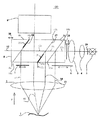
図1に、本発明の顕微鏡の一実施例を示した。この顕微鏡は、全体として、図面参照符号「100」で示す。 FIG. 1 shows an embodiment of the microscope of the present invention. This microscope is generally indicated by reference numeral “100” in the drawing.
顕微鏡100は、主対物レンズ2と、とりわけズームシステムとして構成される拡大システム9とを有する。主対物レンズ2及び拡大システム9から構成される光学システムの光軸は、図面参照符号「11」を付して示した。顕微鏡100の観察チャンネル(複数)は、この光軸11に対し平行に延在する。図1に示した通り、この光軸11は、主対物レンズ2(の主光軸)に関する拡大システム9の非対称的な配置によって引き起こされる折れ曲がり(屈折)を主対物レンズ2内に有する。主対物レンズ2と拡大システム9との間のこの非対称的位置関係は、ある種の使用態様に対しては有利であることがわかる。例えば、後述の6°照明(部分光線束13)の照明瞳が十分に大きい場合に、拡大システム9に対し主対物レンズ2が中心的ないし対称的位置に配されているとすれば、周辺光線は遮断されてしまうであろう。というのは、この場合、主対物レンズ2の図1の紙面に向かって右端が、部分光線束13の照明瞳の中に入ってしまうからである。
The
観察対象1を照明するための光は、光源3から射出されプリズムブロック8として構成された偏向装置を介して観察対象1へ入射する。光源3と偏向装置8との間には、例えば、2つのレンズ4、5及び2つのシャッタ29、28が配される。光源3としては、顕微鏡で一般的に使用されるあらゆる光源、例えば白熱電球、光ファイバ照明装置、放電管ランプ、レーザ等のコヒーレント及び/又はインコヒーレント光源をとりわけ使用することができる。
Light for illuminating the
プリズムブロック8は、(完全及び/又は部分)反射性の面(完全及び/又は部分ミラー面)として構成される全部で3つの偏向要素16、17、18を有する。
The prism block 8 has a total of three
偏向要素16は、完全に(全面が)物理的ビームスプリッタとして構成され、偏向要素17は、少なくとも部分的(局所的)に(少なくとも面の一部が)物理的ビームスプリッタとして構成される。即ち、図1に示した構造ないし位置関係では、光源3から射出され紙面に向かって右側から偏向要素16、17に入射する光線束(模式的に1つの直線として図示した)12aの横断面は不変のまま維持される。光線束12aの分配は、偏向要素16、17の横断面全体に亘って一様に行われる。図から明らかな通り、偏向装置8の照明軸12に沿って進行(伝播)する光線束12aは、偏向要素16において、反射により生成する第1の部分光線束13と、透過により生成する第2の部分光線束12bとに分割(分配)される。部分光線束13は、主対物レンズ2を通過した後、観察対象1のための6°照明として利用することが可能となる。
The
偏向要素16の透過により生成した部分光線束12bは、第2の偏向要素17において、同様にまた部分的に反射・透過する。反射により生成する部分光線束は図面参照符号「14」、透過により生成する部分光線束は図面参照符号「12c」で示した。反射により生成した部分光線束14は、まず、部分光線束13とほぼ平行に進行する。そして、主対物レンズ2を通過した後、観察対象1のための+2°照明として利用することが可能となる。
The
偏向要素17の透過により生成した部分光線束12cは、次いで、第3の偏向要素18に入射する(偏向要素18は完全反射性に構成すると好都合である)。偏向要素18において反射され、反射後のものとして図面参照符号「15」で示した部分光線束は、主対物レンズ2を通過した後、同様に、観察対象1を照射する。部分光線束15は、観察対象1のための−2°照明を構成する。更に配設されたシャッタ6、7によって、部分光線束13、14、15の完全な遮断(オフ切換)又は部分的な遮断(絞り)を実行することができる。このため、例えば眼を観察する場合、場合によっては妨害的に作用する角膜反射を阻止したり、或いは赤色反射のコントラストを改善したりすることが可能となる。
The partial beam bundle 12c generated by the transmission of the deflecting
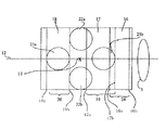
偏向要素ないし反射面16、17、18に対する顕微鏡の上述の観察ビーム路(図1)の位置関係は、図2から明確に見出すことができる。図2には、偏向装置8の下面8a上に各偏向要素を投影したものを示した。偏向要素16、17、18の各下端16a、17a、18aは、これらは実際に下面8a内で延在しており、実線で図示した。偏向要素16、17、18の上端16b、17b、18bは、これらは上面8a内で延在しており、それぞれ破線で図示した。
The positional relationship of the aforementioned observation beam path (FIG. 1) of the microscope with respect to the deflecting elements or reflecting
図2から分かる通り、顕微鏡の観察光路は、主観察者ないし執刀医のための2つの観察光路(観察チャンネル)22a、22bと、副観察者ないし助手のための2つの観察光路(観察チャンネル)23a、23bとから構成される。 As can be seen from FIG. 2, the observation light path of the microscope has two observation light paths (observation channels) 22a and 22b for the main observer or surgeon and two observation light paths (observation channels) for the sub-observer or assistant. 23a and 23b.
更に、副観察者用光路23a、23bは、偏向要素ないし反射性面(ミラー性面)16、17、18の投影面内には完全に含まれているのに対し、主観察者用光路22a、22bは、偏向要素ないし反射性面16、17、18(特に17)の投影面内には部分的にしか含まれていない(即ち、大部分は、反射性面の投影面外にある)ことも、図2から見出すことができる。偏向要素16、17、18の完全又は部分反射性領域は、図2では、中括弧でくくり、それぞれ図面参照符号「24」、「19」、「20」で示した。ここで再度注意すべきことは、図2に示した実施例では、反射性の領域は、偏向要素16、17、18のほぼ全面に亘って形成されていることである。そのため、例えば、偏向要素17、18を完全反射性に構成すると、観察光路23a、23bは阻止(遮断)されるため、そのように構成された顕微鏡は、観察光路22a、22bを使用する主観察者による立体的観察に対してのみ適することとなる。
Further, the sub-observer
これに対し、偏向要素17、18を部分反射性に構成すると、(副観察者用)観察光路23a、23bを介した観察対象1の観察も可能となる。
On the other hand, if the
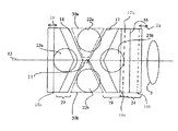
図示の観察光路における光の利用を好適化するために、好ましくは、偏向要素17、18を部分的(局所的)に完全反射性に構成する。即ち、偏向要素17、18の領域ないし面をすべて(全面を)完全反射性とするのではなく、部分的(局所的)に半透過性ないし部分反射性に構成したり、或いは部分的(局所的)に完全透過性に構成したりする。この態様については、図3を用いて詳細に説明する。
In order to optimize the use of light in the illustrated observation beam path, the
図3に示したように、偏向要素17、18は、部分的(局所的)にのみ完全反射性に構成される。偏向要素17、18の下端及び上端を、図2の場合と同様に、17a、17b及び18a、18bでそれぞれ示した。偏向要素17の端部17aと17bとの間には、上端19a及び下端19bを有し、図示の投影面において矢尻状をなす領域19が形成される。この領域19は、偏向要素17の完全反射性領域を構成する。上端19bの図3の紙面に向かって右側の領域(図面参照符号「17c」を付した)、及び下端19aの図3の紙面に向かって左側の領域(図面参照符号「17d」を付した)は、何れも透過性(特に完全透過性)に構成されるため、観察チャンネル(観察光路)23bないし22a、22bと完全反射性領域19との間の相応の重畳(重なり)領域は、何れも小さくすることができる。そのため、観察チャンネル22a、22b及び23bを介した実質的に阻害を受けない観察が保証される。
As shown in FIG. 3, the
偏向要素18も同様に構成され、図3では、完全反射性の領域を図面参照符号20で示した。図2に示した実施例と比べると、完全反射性領域20と観察チャンネル23aとの間の重畳(重なり)著しく減少されているため、副観察者は、観察光路(観察チャンネル)23a、23bを利用したステレオスコピックな観察を全体的に(ほぼ完全に)行うことができる。完全反射性領域19と観察光路22a、22bとの間の重畳(重なり)も、図2に示した実施例のものと比べると大きく減少されている。
The deflecting
図3の完全反射性領域19、20は、図1において、偏向要素17、18上に太い実線によって模式的に示した。
The fully
なお、完全反射性領域19、20と観察光路22a、22b、23a、23bとの間の重なり(重畳)は、ある種の適用例においては望まれる赤色反射を生成するためにある程度必要とされることに注意すべきである。
It should be noted that the overlap between the fully
偏向要素17、18において完全反射性領域19、20の寸法ないし形状を相応に構成することよって、この赤色反射は、例えば強度(明るさ)及びコントラストに関して、適正化することができる。
By appropriately configuring the dimensions or shape of the fully
本発明の照明装置の更なる一実施例を、図4及び図5を用いて説明する。 A further embodiment of the lighting device according to the present invention will be described with reference to FIGS.
図4から見出すことができる通り、図4に示した顕微鏡は、図1に示した顕微鏡とほぼ同様に構成されているため、同じ構造要素ないし部材には、同じ図面参照符号を付した。図4の顕微鏡は、図1の顕微鏡とは以下の点で異なる。即ち、偏向装置は、単一(一体)のプリズムブロックとして構成されるのではなく、機械的ないし空間的に互いに分離した2つのプリズムブロック48、49の組合せとして構成される。 As can be seen from FIG. 4, the microscope shown in FIG. 4 is configured in substantially the same manner as the microscope shown in FIG. 1, and thus the same structural elements or members are denoted by the same reference numerals. The microscope of FIG. 4 differs from the microscope of FIG. 1 in the following points. That is, the deflecting device is not configured as a single (integral) prism block, but as a combination of two prism blocks 48 and 49 that are mechanically or spatially separated from each other.
図5から明確に見出すことができる通り、例えば図3に示したような一体ないしワンピースのプリズムブロックから、2つの楔状断片部分30a、30bを除去することにより、2つのプリズムブロックを有する図4及び図5に示した実施例の偏向装置を構成することができる。このような断片部分の除去は、複数のプリズムブロックの個々のプリズム要素間の偏向要素を構成する境界面に典型的に現れるような接合面が生じるのを効果的に回避できるという利点がある。このような構造は、2つのプリズムの接合面同士は、実際上理想的には平行平面ないし面一に構成することができず、更に、使用される接合剤は、互いに接合されるべきプリズムとは多少異なる屈折率(光学特性)を有するので、好都合である。接合を行う場合は、全体として、通常の如く、境界面において反射作用ないし屈折作用が生じるため、二重像が生じ得る。このような二重像の生成は、図4及び図5に示したような本発明の顕微鏡の実施例の構造では、主観察者に対しても副観察者に対しても大幅に回避することが可能となる。なお、2つのプリズムブロックを有するプリズム複合(組合せ)システムは、上述のような方法で単一ないしワンピースのプリズムブロックを加工ないし切断処理することにより製造しなければならないというわけでは必ずしもないということに注意すべきである。1つのプリズムを切断加工するのではなく、初めから2つのプリズムブロックを各別に製造することも同様に可能である。
As can be clearly seen from FIG. 5, by removing the two wedge-shaped
断片部分30a、30bを除去した部位に、ブロック状ガラス部材を挿入することも可能であり、そのため、主観察者も副観察者も同じ観察条件で観察することを保証することが可能となる。また、主観察者ないし副観察者の観察光路間に場合によって生じる合焦作用の相違を補償するために、そのようなブロック状ガラス部材を完全に取り除き、付加的に光学的な結像作用を有するレンズを副観察者又は主観察者の観察光路に設けることも同様に可能である。
It is also possible to insert a block-shaped glass member into the portion from which the
上述の通り、+/−2°照明は、赤色反射を適切に観察するために利用される。+2°照明から−2°照明への照明の切換は、患者の眼球が例えば水晶体超音波吸引術を受けている際に、手術者から離れる方向に回転する場合に、赤色反射を改善するためにとりわけ利用されるべきである。従来の顕微鏡では、回転調節つまみを操作して+/−2°ミラーを動的に相応の位置ないし状態に合せなければならなかった。これに対し、本発明では、+2°/−2°の同時照明を簡単な態様で実現することができるため、手術者は、本来の手術作業に対する集中力を減殺するようなその種の煩わしい作業をする必要がなくなる。 As mentioned above, +/− 2 ° illumination is used to properly observe red reflections. Switching the illumination from + 2 ° illumination to -2 ° illumination is to improve the red reflection when the patient's eyeball rotates away from the operator, for example when undergoing phacoemulsification It should be used especially. In the conventional microscope, the +/- 2 [deg.] Mirror has to be dynamically adjusted to the corresponding position or state by operating the rotation adjusting knob. On the other hand, in the present invention, simultaneous illumination of + 2 ° / −2 ° can be realized in a simple manner, so that the operator can perform such troublesome work that reduces the concentration on the original surgical work. There is no need to do.
偏向要素の完全反射性領域と観察光路(チャンネル)との重なり(重畳)を簡単な態様で変化させることができるため、主観察者に対しても副観察者に対してもそれぞれ2つの観察チャンネルへ適正な赤色反射を生成する(差込入射する)ことが可能となる。+2°照明は、通常、患者の眼球が中心に合せられている場合の赤色反射の観察に利用され、−2°照明は、とりわけ、患者の眼球が中心からずれている場合に有利に利用することができる。 Since the overlap (overlapping) between the completely reflective region of the deflecting element and the observation optical path (channel) can be changed in a simple manner, there are two observation channels for both the primary observer and the secondary observer. It is possible to generate an appropriate red reflection (injection). + 2 ° illumination is typically used to observe red reflections when the patient's eye is centered, while -2 ° illumination is particularly beneficial when the patient's eye is off center. be able to.
本発明の照明装置は、実際の使用に際しても取り扱いが極めて容易である。ただ1つのプリズムブロック又は2つのプリズムブロックへ複数の偏向要素を組み込むことにより、偏向要素16、17、18間の間隔を適正化するための調節作業は、完全にないし大幅に回避することができる。図1及び図4に示した実施例では、双方向矢印25、58、59で示されるような方向に、プリズムブロック8ないし2つのプリズムブロック48、49を軸12に沿ってそれぞれ摺動することができる。
The lighting device of the present invention is extremely easy to handle in actual use. By incorporating a plurality of deflecting elements into just one prism block or two prism blocks, the adjustment work for optimizing the spacing between the deflecting
更に、偏向要素16、17、18を部分的(局所的)に黒色(geschwaerzt)となるよう構成することも可能である。この態様により、不所望の反射(光)を効果的に抑制することができる。また、例えば偏向装置8ないし48、49の下面のきわに及び、特に図4の実施例では、内面(2つのプリズムの各対向面)上に吸収性要素、とりわけ金属薄板等の(吸収性及び/又は反射性)プレートを配し、これによって同様に、反射の繰り返しによる不所望の反射(光)、例えば偏向要素16、17、18からの入射光の主対物レンズ2における不所望の散乱光が接眼レンズ系に入射すること等、を阻止することも可能である。そのようなプレートは、図1では、図面参照符号「17e」を付して模式的に示した。なお、プレート17eは、図1では、偏向要素8の下面から下方に短くかつ光軸11の主対物レンズ2の上側の部分に対し平行に延在しているが、不所望の反射・散乱光の生成態様により、主対物レンズ2の上面付近までの任意の長さに延長したり、光軸11の上記部分に対し所定の角度をなすよう屈曲したりすることも可能であり、また目的に応じ種々の位置・寸法・形状を有するよう構成することも可能である。また、図4では、例えば光トラップ又は光学フィルタとして、例えば黒色(非選択的ないし完全吸収性)又は選択的吸収性に構成されるこの種の吸収性の表面被覆要素を図面参照符号「17f」を付して一点鎖線で示した。
Furthermore, it is also possible to configure the
表面の黒色化(黒色物質施与)によって、とりわけ内部反射を阻止することも可能となる。例えば金属薄板17e又は表面被覆要素17f等の付加要素によって主対物レンズにおける不所望の反射を阻止することができる。
Blackening of the surface (black substance application) makes it possible in particular to prevent internal reflection. Undesired reflections at the main objective can be prevented by additional elements such as, for example, a
図1のプリズムブロックは、とりわけ、回転すると互いに対し回転対称をなすほぼ同一の2つのプリズムブロックを使用して製造することができるため、回転対称的にずらされて配される2つのプリズム間において、1つの平行四辺形状ブロック部分(区画)を使用することが可能となる。 The prism block of FIG. 1 can be manufactured using, in particular, two substantially identical prism blocks that are rotationally symmetric with respect to each other when rotated, so that between two prisms that are offset in rotational symmetry. One parallelogram block portion (section) can be used.
なお、上述の顕微鏡の各実施例では、観察チャンネルは、観察軸11に対し実質的に対称的に形成されることに注意すべきである。更に、この観察軸は、主対物レンズ2の中心軸ないし主光軸に必ずしも対応するわけではないことにも注意すべきである。
It should be noted that in each embodiment of the microscope described above, the observation channel is formed substantially symmetrically with respect to the
図6に、本発明の偏向装置の更に他の一実施例を、図1又は図4の矢印Pが指す方向に対応する方向に向かって眺めた様子を示した。図6に示した、プリズムブロックとして構成される偏向装置は、2つの偏向要素16、17を有するが、偏向要素16は、物理的ビームスプリッタとして、偏向要素17は、ほぼ完全反射性に構成される。図1〜図5に示したものに対応する、偏向要素16、17の下端16a、17aが図示されている。対応する上端については図示を省略した。可読性の観点から明示していないが、各偏向要素ないし偏向面16、17は、紙面に向かって斜め右方に延在していることに注意すべきである。偏向要素16は、本発明の照明装置の上述の各実施例のものと同様に6°照明を生成するために利用され、偏向要素17は、+2°照明を生成するために利用される。図6では、偏向要素17の左隣にステレオ顕微鏡の観察光路22a、22bが形成される。この実施例では、観察光路22a、22bに、観察光路(を通過する光)に対し透過性のブロック状ガラス部材60、61が配される。このようなブロック状ガラス部材を挿入することによって、観察光路の瞳の狭窄(制限)が実現可能となるため、照明装置ないし顕微鏡の構造高さを全体として減少することが可能となる。更に、このような偏向装置は、図示の軸12の方向に関し従来の偏向装置よりも長さを短くすることができる。というのは、とりわけ適性かつけられのない観察を実現するために、偏向装置の2つ観察光路22a、22bを指向する部分は、該観察光路22a、22bに向かって徐々に幅が狭くなるよう構成される(テーパー化される)からである。ブロック状ガラス部材は、プリズムブロックとして構成される偏向装置と接合するのが好ましい。尤も、ブロック状ガラス部材は、偏向装置とは接合せず分離しておき、必要が生じた場合にのみ作動ないし目的位置に挿入して使用することも可能である。
FIG. 6 shows a state in which another embodiment of the deflecting device of the present invention is viewed in a direction corresponding to the direction indicated by the arrow P in FIG. 1 or FIG. The deflecting device configured as a prism block shown in FIG. 6 has two deflecting
なお、図6では光源は図示を省略していることに注意すべきである。更に、光源と偏向装置との間に配されるべき光学システムに関しては、図面参照符号4を付したレンズを1つだけ代表として示したことにも注意すべきである。
Note that the light source is not shown in FIG. It should also be noted that with respect to the optical system to be arranged between the light source and the deflecting device, only one lens with
1 観察対象
2 主対物レンズ
3 光源
4、5 レンズ
6、7 シャッタ
8 偏向装置(プリズムブロック)
8a 偏向装置の下面
8b 偏向装置の上面
9 拡大システム
11 光軸
12 偏向装置の軸
12a、12b、12c 部分光線束
14、15、16 部分光線束
16、17、18 偏向要素
16a、17a、18a 偏向要素の下端(下縁)
16b、17b、18b 偏向要素の上端(上縁)
17e 金属薄板等のプレート
17f 表面被覆(遮蔽)部材
19、20 偏向要素17、18の反射性領域
22a、22b 主観察者の観察光路
23a、23b 副観察者の観察光路
24 偏向要素16の反射性領域
25 双方向矢印
28、29 シャッタ
30a、30b 楔状ブロック部材
48、49 偏向装置(プリズムブロック)
58、59 双方向矢印
60、61 ブロック状ガラス部材
100 顕微鏡
DESCRIPTION OF
8a Lower surface of the
16b, 17b, 18b Upper end (upper edge) of deflection element
17e Plates such as thin metal plates 17f Surface coating (shielding)
58, 59
Claims (15)
前記偏向装置(8;48、49)は、少なくとも部分的に物理的ビームスプリッタとして構成されかつ、唯一の光軸に沿って配された2つの偏向要素(16、17)を有すること、
前記2つの偏向要素(16、17)の少なくとも1つは、部分的に完全反射性に構成されること、及び
前記偏向装置は、一体のプリズムブロック(8)として構成されるか、又は、空間的に互いに分離する2つのプリズムブロック(48,49)から構成されること、
を特徴とする照明装置。 An illumination device for a microscope having at least one observation optical path, the illumination device comprising: an illumination system; and a deflection device for deflecting a light beam emitted from the illumination system toward an observation object. Is configured to allow illumination of the observation object with a plurality of different illumination angles with respect to the at least one observation light path,
Said deflecting device (8; 48, 49) has two deflecting elements (16, 17) arranged at least partly as a physical beam splitter and arranged along a single optical axis ;
At least one of the two deflection elements (16, 17) is configured to be partially fully reflective ; and
The deflecting device is configured as an integral prism block (8) or is composed of two prism blocks (48, 49) spatially separated from each other;
A lighting device characterized by the above.
を特徴とする請求項1に記載の照明装置。 The lighting device according to claim 1, wherein the deflection device comprises three deflection elements (16, 17, 18) arranged along the only optical axis .
を特徴とする請求項1又は2に記載の照明装置。 The illumination device according to claim 1 or 2, wherein two deflection elements are configured so that + 2 ° illumination and -2 ° illumination on the observation target can be performed simultaneously.
前記偏向装置は、前記観察対象に対する+2°照明及び−2°照明を同時に実行可能すると共に唯一の光軸に沿って配された2つの偏向要素(17、18)を有すること、及び
前記2つの偏向要素(17、18)の少なくとも1つは、部分的に完全反射性に構成されること、及び
前記偏向装置は、一体のプリズムブロック(8)として構成されるか、又は、空間的に互いに分離する2つのプリズムブロック(48,49)から構成されること、
を特徴とする照明装置。 An illumination device for a microscope having at least one observation optical path, the illumination device comprising: an illumination system; and a deflection device for deflecting a light beam emitted from the illumination system toward an observation object. Is configured to allow illumination of the observation object with a plurality of different illumination angles with respect to the at least one observation light path,
The deflecting device has two deflecting elements (17, 18) that can simultaneously perform + 2 ° illumination and -2 ° illumination on the object to be observed and are arranged along a single optical axis ; and At least one of the deflection elements (17, 18) is configured to be partially fully reflective ; and
The deflecting device is configured as an integral prism block (8) or is composed of two prism blocks (48, 49) spatially separated from each other;
A lighting device characterized by the above.
を特徴とする請求項1〜4の何れか一項に記載の照明装置。 The illumination device according to any one of claims 1 to 4, wherein the deflecting device is configured as a prism composite system having a plurality of partially reflective surfaces.
を特徴とする請求項1〜5の何れか一項に記載の照明装置。 The illumination device according to any one of claims 1 to 5, wherein the deflection device is configured as an integral prism block (8).
を特徴とする請求項1〜5の何れか一項に記載の照明装置。 The illumination device according to any one of claims 1 to 5, wherein the deflection device comprises two prism blocks (48, 49) that are spatially separated from each other.
を特徴とする請求項8に記載の顕微鏡。 The microscope according to claim 8, comprising four observation channels (22a, 22b, 23a, 23b).
を特徴とする請求項8又は9に記載の顕微鏡。 The microscope according to claim 8 or 9, comprising a plurality of shutters (6, 7) for selectively switching on and off the illumination beam path.
を特徴とする請求項8〜10の何れか一項に記載の顕微鏡。 The deflection device (8; 48, 49) is configured to be slidable transversely with respect to the optical axis of the microscope defined by the relative positional relationship between the main objective lens (2) and the magnifying system (9). The microscope according to any one of claims 8 to 10, wherein:
を特徴とする請求項9〜11の何れか一項に記載の顕微鏡。 The microscope according to any one of claims 9 to 11, further comprising a plurality of block-shaped glass members that can be inserted into the four observation channels (22a, 22b, 23a, 23b).
前記偏向装置が、少なくとも部分的に物理的ビームスプリッタとして構成されかつ唯一の光軸に沿って配された2つの偏向要素(16、17)を有すること、及び、
顕微鏡の複数の観察チャンネル(22a、22b)に挿入可能であり、該観察チャンネル(22a、22b)に対し透過性であり、かつ該観察チャンネル(22a、22b)の瞳の狭窄を実現可能にする少なくとも1つのブロック状ガラス部材(60、61)を有すること
を特徴とする顕微鏡。 An illumination system; and a deflecting device for deflecting a light beam emitted from the illumination system toward the observation target, the deflection device having the plurality of different illumination angles with respect to at least one observation optical path. A microscope having an illumination device configured to allow illumination of:
The deflection device comprises two deflection elements (16, 17) at least partly configured as a physical beam splitter and arranged along a unique optical axis ; and
It can be inserted into a plurality of observation channels (22a, 22b) of the microscope, is transparent to the observation channels (22a, 22b), and makes it possible to realize narrowing of the pupil of the observation channels (22a, 22b). A microscope having at least one block-shaped glass member (60, 61).
を特徴とする請求項13に記載の顕微鏡。 The microscope according to claim 13, characterized in that at least one of the two deflection elements (16, 17) is configured to be partially fully reflective.
を特徴とする請求項13又は14に記載の顕微鏡。 The microscope according to claim 13 or 14, wherein at least one of the block-shaped glass members (60, 61) is joined to the deflecting device.
Applications Claiming Priority (2)
| Application Number | Priority Date | Filing Date | Title |
|---|---|---|---|
| DE10311000.3 | 2003-03-06 | ||
| DE10311000A DE10311000C5 (en) | 2003-03-06 | 2003-03-06 | Illumination device for a microscope |
Related Parent Applications (1)
| Application Number | Title | Priority Date | Filing Date |
|---|---|---|---|
| JP2004064838A Division JP4651958B2 (en) | 2003-03-06 | 2004-03-08 | Microscope illumination device |
Publications (2)
| Publication Number | Publication Date |
|---|---|
| JP2009187014A JP2009187014A (en) | 2009-08-20 |
| JP4838331B2 true JP4838331B2 (en) | 2011-12-14 |
Family
ID=32797912
Family Applications (2)
| Application Number | Title | Priority Date | Filing Date |
|---|---|---|---|
| JP2004064838A Expired - Fee Related JP4651958B2 (en) | 2003-03-06 | 2004-03-08 | Microscope illumination device |
| JP2009088763A Expired - Fee Related JP4838331B2 (en) | 2003-03-06 | 2009-04-01 | Microscope illumination device |
Family Applications Before (1)
| Application Number | Title | Priority Date | Filing Date |
|---|---|---|---|
| JP2004064838A Expired - Fee Related JP4651958B2 (en) | 2003-03-06 | 2004-03-08 | Microscope illumination device |
Country Status (4)
| Country | Link |
|---|---|
| US (1) | US7142359B2 (en) |
| EP (1) | EP1455215B2 (en) |
| JP (2) | JP4651958B2 (en) |
| DE (2) | DE10311000C5 (en) |
Families Citing this family (18)
| Publication number | Priority date | Publication date | Assignee | Title |
|---|---|---|---|---|
| US7167315B2 (en) * | 2004-04-20 | 2007-01-23 | Microvision, Inc. | Apparatus and method for combining multiple electromagnetic beams into a composite beam |
| DE102004050651A1 (en) * | 2004-08-06 | 2006-03-16 | Carl Zeiss Surgical Gmbh | Lighting device and observation device |
| JP4786215B2 (en) * | 2005-04-04 | 2011-10-05 | 株式会社トプコン | Surgical microscope equipment |
| EP1837695A1 (en) * | 2006-03-22 | 2007-09-26 | Carl Zeiss SMT AG | Catadioptric imaging system with beam splitter |
| US7850338B1 (en) | 2006-09-25 | 2010-12-14 | Microscan Systems, Inc. | Methods for directing light |
| US7852564B2 (en) * | 2006-09-27 | 2010-12-14 | Microscan Systems, Inc. | Devices and/or systems for illuminating a component |
| JP5628038B2 (en) * | 2007-10-16 | 2014-11-19 | コーニンクレッカ フィリップス エヌ ヴェ | Apparatus, system and method for the generation and integration of compact illumination schemes |
| DE102009028229B3 (en) * | 2009-06-10 | 2010-12-09 | Leica Instruments (Singapore) Pte. Ltd. | Illumination device for a surgical microscope |
| JP5347752B2 (en) * | 2009-06-23 | 2013-11-20 | 株式会社ニコン | Stereo microscope |
| DE102009036913B4 (en) * | 2009-08-11 | 2016-01-28 | Carl Zeiss Meditec Ag | Surgical microscope with illumination device |
| DE102009046449B3 (en) * | 2009-11-06 | 2011-05-12 | Leica Instruments (Singapore) Pte. Ltd. | stereomicroscope |
| DE102010003295B4 (en) * | 2010-03-25 | 2014-09-04 | Leica Microsystems (Schweiz) Ag | Illumination device for a surgical microscope |
| DE102010028169A1 (en) | 2010-04-23 | 2011-10-27 | Leica Microsystems (Schweiz) Ag | Illumination device for a surgical microscope |
| DE102012213369B4 (en) * | 2012-07-30 | 2016-01-28 | Leica Microsystems (Schweiz) Ag | Stereo microscope with four observation channels |
| EP3136149A1 (en) * | 2015-08-24 | 2017-03-01 | Leica Instruments (Singapore) Pte. Ltd. | Illumination and observation system for an ophthalmic microscope, ophthalmic microscope comprising such a system, and microscopying method |
| EP3136150A1 (en) * | 2015-08-24 | 2017-03-01 | Leica Instruments (Singapore) Pte. Ltd. | Illumination and observation system for an ophthalmic microscope, ophthalmic microscope and microscopying method using four red reflex observation pupils |
| JP2017079904A (en) * | 2015-10-26 | 2017-05-18 | ソニー株式会社 | Surgical microscope, image processing device, and image processing method |
| TW202104973A (en) | 2019-07-11 | 2021-02-01 | 以色列商奧寶科技有限公司 | Multi-modal wide-angle illumination employing a compound beam combiner |
Family Cites Families (20)
| Publication number | Priority date | Publication date | Assignee | Title |
|---|---|---|---|---|
| GB1277979A (en) * | 1969-09-11 | 1972-06-14 | Tokyo Shibaura Electric Co | Reflecting microscope |
| DE3327672C2 (en) * | 1983-07-30 | 1986-02-20 | Fa. Carl Zeiss, 7920 Heidenheim | Coaxial incident light bright field illumination for stereo microscopes |
| DE3833876A1 (en) * | 1988-10-05 | 1990-04-12 | Zeiss Carl Fa | TWO OPTICALLY MECHANICALLY COUPLED OPERATING MICROSCOPES WITH COAXIAL LIGHTING |
| JP3011950B2 (en) * | 1989-08-23 | 2000-02-21 | 株式会社トプコン | Surgical microscope |
| DE9017990U1 (en) * | 1990-09-08 | 1993-06-24 | Fa. Carl Zeiss, 7920 Heidenheim, De | |
| DE4331635C2 (en) * | 1992-12-22 | 2001-03-15 | Zeiss Carl Fa | Illumination device for an operating microscope with optically-mechanically coupled observer tubes |
| JP3371917B2 (en) * | 1993-07-12 | 2003-01-27 | 株式会社ニコン | Zoom lens with anti-vibration function |
| DE4417273C2 (en) * | 1994-05-18 | 1997-12-11 | Moeller J D Optik | Coaxial illumination device for a binocular, ophthalmic surgical microscope |
| CH689954A5 (en) * | 1994-11-19 | 2000-02-15 | Zeiss Carl Fa | Stereo microscope arrangement with appropriate lighting unit. |
| JPH08164155A (en) * | 1994-12-14 | 1996-06-25 | Nikon Corp | Illuminator for ophthalmology |
| JP3537205B2 (en) * | 1995-02-02 | 2004-06-14 | オリンパス株式会社 | Microscope equipment |
| JPH08257037A (en) * | 1995-03-20 | 1996-10-08 | Nikon Corp | Microscope for operation |
| JP3631302B2 (en) * | 1995-10-11 | 2005-03-23 | オリンパス株式会社 | Stereo microscope |
| DE29601263U1 (en) | 1996-01-25 | 1997-05-28 | Moeller J D Optik | Illumination device for a surgical microscope |
| JPH10133122A (en) * | 1996-10-25 | 1998-05-22 | Nikon Corp | Surgical microscope |
| WO1999059016A1 (en) * | 1998-05-13 | 1999-11-18 | Leica Microsystems Ag | Lighting device for a surgical microscope |
| ATE225046T1 (en) | 1999-12-15 | 2002-10-15 | Moeller Wedel Gmbh | ILLUMINATION DEVICE FOR A SURGICAL MICROSCOPE |
| US20010040726A1 (en) * | 2000-05-08 | 2001-11-15 | Leica Microsystems Ag | Microscope |
| DE10144067A1 (en) | 2001-09-07 | 2003-03-27 | Leica Microsystems | Prism construction for simultaneous 0 DEG - and oblique illumination of a stereo surgical microscope |
| JP4439815B2 (en) * | 2002-08-22 | 2010-03-24 | 株式会社トプコン | Surgical microscope |
-
2003
- 2003-03-06 DE DE10311000A patent/DE10311000C5/en not_active Expired - Fee Related
-
2004
- 2004-02-11 DE DE502004007339T patent/DE502004007339D1/en not_active Expired - Lifetime
- 2004-02-11 EP EP04003065A patent/EP1455215B2/en not_active Expired - Fee Related
- 2004-03-04 US US10/793,548 patent/US7142359B2/en not_active Expired - Lifetime
- 2004-03-08 JP JP2004064838A patent/JP4651958B2/en not_active Expired - Fee Related
-
2009
- 2009-04-01 JP JP2009088763A patent/JP4838331B2/en not_active Expired - Fee Related
Also Published As
| Publication number | Publication date |
|---|---|
| JP2004272263A (en) | 2004-09-30 |
| US7142359B2 (en) | 2006-11-28 |
| EP1455215B1 (en) | 2008-06-11 |
| DE10311000C5 (en) | 2012-05-10 |
| DE502004007339D1 (en) | 2008-07-24 |
| EP1455215B2 (en) | 2012-01-11 |
| DE10311000B4 (en) | 2006-04-06 |
| US20040174591A1 (en) | 2004-09-09 |
| EP1455215A3 (en) | 2005-01-19 |
| EP1455215A2 (en) | 2004-09-08 |
| JP4651958B2 (en) | 2011-03-16 |
| DE10311000A1 (en) | 2004-09-23 |
| JP2009187014A (en) | 2009-08-20 |
Similar Documents
| Publication | Publication Date | Title |
|---|---|---|
| JP4838331B2 (en) | Microscope illumination device | |
| JP2999206B2 (en) | Two surgical microscopes optically and mechanically coupled | |
| JP3541051B2 (en) | Illumination device for operating microscope and operating microscope | |
| US7907336B2 (en) | Surgical microscope having an illuminating arrangement | |
| US4138191A (en) | Operating microscope with two pairs of stereo eye-piece lenses | |
| US7283298B2 (en) | Stereoscopic microscope | |
| JP5259570B2 (en) | Illumination device and observation device | |
| US5898518A (en) | Stereo microscope arrangement | |
| JP2009116070A (en) | Stereomicroscope | |
| JP3701331B2 (en) | Stereo microscope | |
| JP3534733B2 (en) | Fixed high magnification switching microscope | |
| JP4267278B2 (en) | Illumination device for simultaneous illumination from two different directions | |
| JP2014026285A (en) | Stereomicroscope having four observation channels | |
| JP2009110004A (en) | Illumination device for light microscope and light microscope with illumination device | |
| JP3891663B2 (en) | Stereo microscope | |
| JPS5867251A (en) | Operation microscope | |
| JP4598449B2 (en) | microscope | |
| JP4225802B2 (en) | Illumination insertion device for optical observation equipment | |
| JP3162115U (en) | Illumination device for operation microscope and operation microscope | |
| US7088504B2 (en) | Surgical microscope | |
| US10531984B2 (en) | Ophthalmologic microscope system | |
| JP3693760B2 (en) | Surgical microscope | |
| US8941915B2 (en) | Illuminating device for an operating microscope | |
| US20130229626A1 (en) | Microscope Having A Switchable Documentation Beam Path | |
| JP2000028927A (en) | Microscope for surgical operation |
Legal Events
| Date | Code | Title | Description |
|---|---|---|---|
| A711 | Notification of change in applicant |
Free format text: JAPANESE INTERMEDIATE CODE: A711 Effective date: 20100222 |
|
| TRDD | Decision of grant or rejection written | ||
| A01 | Written decision to grant a patent or to grant a registration (utility model) |
Free format text: JAPANESE INTERMEDIATE CODE: A01 Effective date: 20110906 |
|
| A01 | Written decision to grant a patent or to grant a registration (utility model) |
Free format text: JAPANESE INTERMEDIATE CODE: A01 |
|
| A61 | First payment of annual fees (during grant procedure) |
Free format text: JAPANESE INTERMEDIATE CODE: A61 Effective date: 20110929 |
|
| FPAY | Renewal fee payment (event date is renewal date of database) |
Free format text: PAYMENT UNTIL: 20141007 Year of fee payment: 3 |
|
| R150 | Certificate of patent or registration of utility model |
Ref document number: 4838331 Country of ref document: JP Free format text: JAPANESE INTERMEDIATE CODE: R150 Free format text: JAPANESE INTERMEDIATE CODE: R150 |
|
| R250 | Receipt of annual fees |
Free format text: JAPANESE INTERMEDIATE CODE: R250 |
|
| R250 | Receipt of annual fees |
Free format text: JAPANESE INTERMEDIATE CODE: R250 |
|
| R250 | Receipt of annual fees |
Free format text: JAPANESE INTERMEDIATE CODE: R250 |
|
| R250 | Receipt of annual fees |
Free format text: JAPANESE INTERMEDIATE CODE: R250 |
|
| R250 | Receipt of annual fees |
Free format text: JAPANESE INTERMEDIATE CODE: R250 |
|
| R250 | Receipt of annual fees |
Free format text: JAPANESE INTERMEDIATE CODE: R250 |
|
| LAPS | Cancellation because of no payment of annual fees |