JP3891663B2 - Stereo microscope - Google Patents
Stereo microscope Download PDFInfo
- Publication number
- JP3891663B2 JP3891663B2 JP26623697A JP26623697A JP3891663B2 JP 3891663 B2 JP3891663 B2 JP 3891663B2 JP 26623697 A JP26623697 A JP 26623697A JP 26623697 A JP26623697 A JP 26623697A JP 3891663 B2 JP3891663 B2 JP 3891663B2
- Authority
- JP
- Japan
- Prior art keywords
- optical system
- illumination
- observation
- stereomicroscope
- light
- Prior art date
- Legal status (The legal status is an assumption and is not a legal conclusion. Google has not performed a legal analysis and makes no representation as to the accuracy of the status listed.)
- Expired - Fee Related
Links
- 230000003287 optical effect Effects 0.000 claims description 320
- 238000005286 illumination Methods 0.000 claims description 210
- 238000003384 imaging method Methods 0.000 claims description 27
- 230000002194 synthesizing effect Effects 0.000 claims description 5
- 230000001678 irradiating effect Effects 0.000 claims description 2
- 238000010586 diagram Methods 0.000 description 30
- 239000000835 fiber Substances 0.000 description 20
- 230000000007 visual effect Effects 0.000 description 15
- 230000000694 effects Effects 0.000 description 14
- 238000000034 method Methods 0.000 description 11
- 239000006059 cover glass Substances 0.000 description 7
- 230000004907 flux Effects 0.000 description 7
- 238000001356 surgical procedure Methods 0.000 description 6
- 238000012937 correction Methods 0.000 description 4
- 230000031700 light absorption Effects 0.000 description 4
- 230000015572 biosynthetic process Effects 0.000 description 2
- 230000000903 blocking effect Effects 0.000 description 2
- 210000004204 blood vessel Anatomy 0.000 description 2
- 210000004556 brain Anatomy 0.000 description 2
- 238000001000 micrograph Methods 0.000 description 2
- 241001272720 Medialuna californiensis Species 0.000 description 1
- 206010057430 Retinal injury Diseases 0.000 description 1
- 239000011248 coating agent Substances 0.000 description 1
- 238000000576 coating method Methods 0.000 description 1
- 238000011161 development Methods 0.000 description 1
- 210000003128 head Anatomy 0.000 description 1
- 238000007689 inspection Methods 0.000 description 1
- 238000005259 measurement Methods 0.000 description 1
- 210000005036 nerve Anatomy 0.000 description 1
- 230000002093 peripheral effect Effects 0.000 description 1
- 238000012545 processing Methods 0.000 description 1
- 230000002250 progressing effect Effects 0.000 description 1
- 238000007493 shaping process Methods 0.000 description 1
- 238000003786 synthesis reaction Methods 0.000 description 1
- 238000002834 transmittance Methods 0.000 description 1
Images


Landscapes
- Microscoopes, Condenser (AREA)
Description
【0001】
【発明の属する技術分野】
本発明は実体顕微鏡の照明系に関し、特に手術用顕微鏡の照明に関する。
【0002】
【従来の技術】
近年、医療分野において手術用顕微鏡を用いた手術が普及している。特に、最近では、患者への負担を最小限にするために、手術機械,手術手技の開発が進んでいる。これに従い、複数人が自由な方向から顕微鏡像を長時間観察しながらの作業も必要となっている。しかしながら、現在広く用いられている手術用顕微鏡は、観察方法自体に制約があるため、改良が望まれている。
【0003】
そこで、このような要望に応えるために、ドイツ公開特許第19541237A1号や特開平6−337351号公報により、新たな観察系方式(以下、シングルズーム型光学系と称する)が提案されている。
【0004】
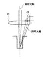
図31は、ドイツ公開特許第19541237A1号で提案された手術用顕微鏡の構成を示す部分側面断面図である。この手術用顕微鏡では、第1乃至第3の3つの光学成分72,73,74によりアフォーカル光学系が構成されており、第1の光学成分72及び第2の光学成分73は、夫々主対物レンズ71と共通の光軸に沿って移動可能になっている。又、照明装置は、ライトガイドファイバー75,レンズ系76,77,及び偏向部材78からなり、レンズ系76,77を経たライトガイドファイバー75からの光を偏向部材78により物体面の方向へ所定の角度偏向し対物レンズ71を介して照射する。
【0005】
図32は、特開平6−337351号公報に開示された実体顕微鏡の構成を示す図である。この実体顕微鏡は、対物レンズ81とこれと共通の光軸の変倍光学系82と接眼光学系(不図示)とを備え、変倍光学系82は物体側から順に、正の第1レンズ群82aと負の第2レンズ群82bと正の第3レンズ群82cとが配置されて構成され、第1レンズ群82a及び第3レンズ群82cを光軸に沿って移動させて変倍を行うようにしたシングルズーム型光学系である。
【0006】
ここでは、シングルズーム型光学系を、「ズーム機能を有し1本の光軸を共有する光学系を備え、この光学系から射出された光束から左右像を形成するために立体観察光束を取り出す左右開口と、これら左右開口で取り出された光束を目視又は撮影するために結像させる光学系を有する観察系」と定義する。この光学系の主な特徴は、左右共通のズーム型の光学系としたため、同時に多方向からの立体観察が可能なことである。図31,32に示した光学系は、これが可能になっている。
【0007】
【発明が解決しようとする課題】
手術用顕微鏡においては、目視又は撮影系での観察を行うため、術部に照明光を照射して観察範囲を明るく均一に照明する照明系を備えている必要がある。しかし、それだけでなく、例えば、▲1▼照明方式自体の改善、▲2▼術中における照明装置の操作上の煩雑さの改善、▲3▼照明装置の交換時の煩雑な作業の改善、▲4▼手術内容,分野に応じた柔軟な照明効果等が望まれる。
しかしながら、図31,32に示された顕微鏡をはじめとして従来のシングルズーム型光学系に用いられている照明系は、従来の照明系をそのまま用いるか、単にそれらを組み合わせただけのものであり、前記▲1▼〜▲4▼のような照明系に求められる要望を満足することはできない。
【0008】
又、脳外科分野では、頭部に小さい穴をあけ、この穴を通して内部の手術が行われる。このとき、その穴の底部や側面の観察において影を生じることなく観察したい。又、多少の血管や神経等が観察視野に入っても観察系で観察可能な部位であれば、影を生ぜずに観察したいという要望がある。
しかし、図31に示された従来のシングルズーム方式の手術用顕微鏡では、図33に示すように、対物レンズ71の光軸から離れた位置に照明光の偏向部材78が配置されている。従って、同図に示すように、照明系の光軸が観察系の光軸に対して傾き、特に凹部を観察するような場合、照明光束がけられて影を生じてしまう。
【0009】
又、前記特開平6−337351号公報に開示されているシングルズーム型の手術用顕微鏡では、照明系に関する具体的な内容が示されていないため、前述の要望を満足させることはできない。
【0010】
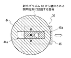
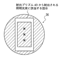
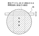
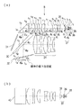
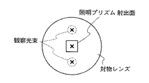
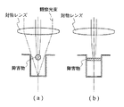
図34は、一般に知られている対物レンズの光軸と同軸な位置に照明プリズムの射出面を設けて同軸照明を実現した手術用顕微鏡の対物レンズ側から見た図である。又、図35(a),(b)は図34の側面図で、夫々90°異なった方向から見た図である。図35では血管のような微小な円筒状の障害物が、対物レンズの光軸を横切るように存在している状態を示している。ここに示された手術用顕微鏡では、図35(a),(b)に示すように、観察光束は穴の底面まで届くため、障害物があっても底面の観察はできるが、照明光束は障害物によって遮られて底面までは届かず、障害物によって影ができてしまうことになる。
【0011】
以上のように、従来のシングルズーム型の手術用顕微鏡では、無影照明を実現することはできなかった。
【0012】
加えて、眼科分野で用いられる手術用顕微鏡では、眼底反射光の観察のために対物レンズの光軸と同軸な照明光を照射する照明方式と、照明光による網膜障害を避けて観察を行うために対物レンズの光軸に対して照明光を傾けて照射する斜照明方式との切替えが必要である。又、その切替えも容易に行えることが好ましい。
又、眼科では、スリットランプと称されるスリット状の平行光を用いて眼の検査が行われているが、スリットランプは外付けの照明装置であり、通常の観察時には邪魔であるため、顕微鏡への着脱が可能になっている。しかし、この作業は煩雑であり、一体的にコンパクトにまとめたいとの要望がある。
【0013】
更に、脳外科,眼科等を含めて、手術に適した照明パターンが望まれているが、従来のものでは照明に自由度がなく実現し難い。例えば、対物光軸に対して傾いた成分のみからなる照明光により観察物の立体感を強調した観察と、通常の観察とを切替えながら観察したい等の要望には応えられていない。
【0014】
そこで、かかる従来技術の問題点に鑑み、本発明は次のような目的を有している。
【0015】
本発明の第1の目的は、同時に複数人による立体視観察が可能で、主側,副側の観察位置の自由度の確保を可能にし、通常観察における術部を明るく均一に照明できるシングルズーム型光学系の手術用顕微鏡を提供することである。
第2の目的は、脳外科分野において、多少の障害物があっても観察系で観察可能な部位には常に無影照明が供給できる手術用顕微鏡を提供することである。詳しくは、シングルズーム型光学系において、ズーミングによる観察光束の間隔や光束径の変化、フォーカシングによる観察光束の光軸間隔の変化によっても、影を生じることなく、明るい照明光を供給し得る手術用顕微鏡を提供することである。又、主側の観察位置や観察者の姿勢の変化、副側の観察位置の変化により観察光軸の回転方向が移動した場合にも、影のない明るい照明光を供給し得る手術用顕微鏡を提供することである。
【0016】
第3の目的は、眼科分野で要求される対物レンズの光軸と同軸な照明方式と、対物レンズの光軸に対して傾いた斜照明方式との切替えが可能で、しかも簡易な構成の照明系を有する手術用顕微鏡を提供することである。
第4の目的は、眼科分野で要求される対物レンズの光軸に対して傾いたスリット状の平行光束を傾斜角又は投影位置を変えて照明する照明方式と前記各照明方式とが切替え可能で、しかも簡易な構成の照明系を有する手術用顕微鏡を提供することである。
第5の目的は、従来顕微鏡では実現不可能であった照明効果を組み合わせた照明が実現でき、しかも照明効果の切替えが容易な手術用顕微鏡を提供することである。
【0017】
【課題を解決するための手段】
上記目的を達成するため、本発明による実体顕微鏡は、光源と、この光源からの光を物体面に照射するための照明光学系と、前記物体面の像を形成する少なくとも結像性能を有する第1の結像光学系と、第1の結像光学系の射出側に配置され左右像を形成するための左右開口と、前記左右像を目視又は撮影するための第2の結像光学系を有する観察光学系と、を備え、前記照明光学系と前記観察光学系との光路を合成するための光路合成手段を有する実体顕微鏡において、前記照明光学系には照明光の照射角度を可変にするための明るさ絞りが備えられており、前記観察光学系の観察視野中心部へ至る観察光束の少なくとも一部に前記照明光学系からの照明光束が常に含まれるようにしたことを特徴とする。
【0018】
又、本発明の実体顕微鏡は、前記明るさ絞りは絞り形状をスリット状に交換可能であることを特徴とする。
又、本発明の実体顕微鏡は、前記照明光学系には、照明範囲の形状を可変にする照野絞りが備えられていることを特徴する。
又、本発明の実体顕微鏡は、前記照野絞りは絞り形状をスリット状に交換可能であることを特徴とする。
又、本発明の実体顕微鏡は、前記第1の結像光学系の光軸と前記照明光学系の光軸とを略一致させていることを特徴とする。
又、本発明の実体顕微鏡は、2組以上の左右の立体観察光学系が備えられていることを特徴とする。
又、本発明の実体顕微鏡は、前記第1の結像光学系は変倍機能を有することを特徴とする。
又、本発明の実体顕微鏡は、前記第1の結像光学系は対物レンズとアフォーカルズーム光学系とを備えていることを特徴とする。
又、本発明の実体顕微鏡は、前記第1の結像光学系の光路上に撮影光学系の光軸を配置したことを特徴とする。
更に、本発明の実体顕微鏡は、前記明るさ絞りは中心部に遮光部を有していることを特徴とする。
【0019】
【発明の実施の形態】
以下、図示した実施例に基づき、本発明を詳細に説明する。
【0020】
第1実施例
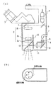
図1は本実施例にかかる実体顕微鏡の構成を示す光軸に沿う断面図である。
本実施例の実体顕微鏡では、固定焦点の対物レンズ1と、アフォーカルズーム光学系2と、接眼レンズを備えた観察鏡筒3とにより観察光学系が構成されている。アフォーカルズーム光学系2は、対物レンズ1側から順に、正の第1レンズ群2a,負の第2レンズ群2b及び正の第3レンズ群2cが配置されて構成されている。変倍は第1レンズ群2a及び第2レンズ群2bを光軸に沿う方向に移動させることにより行われる。本実施例の実体顕微鏡においては、主側観察系として観察鏡筒3のみを備えている。この観察鏡筒3内には左右光路に相当する光学系が配置されており、左右開口は観察鏡筒3の下面の光路入射側に設けられている。又、観察鏡筒3は固定である。アフォーカルズーム光学系2の倍率の変化に応じて、対物レンズ1上の観察光軸の間隔,光束径の大きさが変化する。
又、ミラー4,5及びTVカメラ6により撮影光学系が構成されている。
【0021】
本実施例の実体顕微鏡において、対物レンズ1とアフォーカルズーム光学系2が観察物体面上の像を形成する第1の結像光学系、観察鏡筒内に配置された光学系(不図示)が第2の結像光学系に相当する。ここでは、第1の結像光学系は対物レンズ1とアフォーカルズーム光学系2で構成されているが、結像機能を有する光学系、変倍機能を有する光学系というように機能を分割することなく、結像機能及び変倍機能を併せもった対物レンズを用いてもよい。
更に、本実施例では、対物レンズ1は固定焦点のものを採用したが、可変焦点ものを用いてもよい。又、アフォーカルズーム光学系2はシングルズーム型の光学系であるが、この他の形態のズーム光学系を用いることもできる。
【0022】
一方、照明光学系は、ライトガイドファイバー7と、このライトガイドファイバー7からの光束を成形するためのレンズ8及び照野絞り9と、ミラー10と、レンズ11と、明るさ絞り12と、明るさ絞り12からの照明光束の光軸を対物レンズ1の光軸と一致させるために対物レンズ1とアフォーカルズーム光学系2との間に配置された光路合成用のハーフミラー13と、により構成されている。ライトガイドファイバー7の射出端面は円形である。又、照野絞り9及び明るさ絞り12は、複数のパターンがターレット上に設けられており、かかるターレットを回転させることにより複数の絞り形状を選択可能にしている。
【0023】
ライトガイドファイバー7から発せられた光は、レンズ8,照野絞り9で成形された後、ミラー10で反射されレンズ11で明るさ絞り12の位置にライトガイドファイバー7の端面像を結像する。更に、ハーフミラー13にて照明系の光軸を対物レンズ1の光軸と略一致させて照明光を導光し、対物レンズ1を介して物体面を照明する。本実施例では、照明開口の大きさはレンズ11の口径の大きさで定まり、円形の光束となる。
【0024】
ところで、焦点位置可変の対物レンズ等のフォーカシング機能を有する構成を採用する場合には、フォーカシングにより観察光束の間隔,光束径の大きさの変化を考慮して設定することになる。
このようにすることで、観察光学系で観察可能な物体位置には、常に照明光が導かれるため影なく観察することができる。又、予め大きな照明開口を形成することで、明るく照明できることに加えて、照明光束の一部を遮蔽することで様々な形態の照明方式を容易に実現することができる。
尚、ここで、照明光束とは、視野中心に集光する照明光の対物レンズ1(第1の結像光学系)の光軸とのなす角度を定める照明光束径の大きさのことをいう。
【0025】
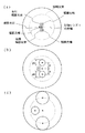
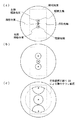
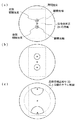
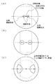
図2は、本実施例の実体顕微鏡の観察光学系と照明光学系との光路を合成するハーフミラー13の位置における視野中心に相当する物体位置へ至る観察光束,撮影光束及び照明光束の範囲を示す図であり、(a)は低倍時,(b)は中倍時,(c)は高倍時の状態を示している。
低倍時は、観察光束が細く、左右の観察光軸の間隔も狭い。高倍時は、観察光束は太く、左右の観察光軸の間隔も広い。この関係は、アフォーカルズーム光学系2のズーム倍率に正比例する関係にある。即ち、観察光束径の大きさφa と、左右の観察光軸と対物レンズ1の光軸との間隔aとは比例関係にある。
【0026】
ところで、実体顕微鏡における観察で重要なのは視野中心であり、特に、手術用顕微鏡の画角は狭くおよそ視野中心の見えで代表して置き換えられる。よって、図2(a)〜(c)に示したように、視野中心へ至る観察光束の位置に対する照明系の射出光束の関係を考えればよい。
観察光学系に対して影のない照明を実現するためには、左右の観察光束の一部が常に照明光の成分を含むようにすることが必要である。具体的には、左右の観察光束と照明光束とが交わるように構成することで実現できる。
【0027】
図2(a)〜(c)に示したように、低倍時には、左右の観察光束の間隔は比較的狭くなり、しかも、観察光束自体が細くなるため、観察光束は全て照明光束に含まれ無影照明を実現できる。高倍時には、観察光束が全て照明光束に含まれることはないが、少なくとも一部は含まれているため、観察系においては影はできない。尚、点線で示した円は照明光束である。
又、本実施例では、撮影光学系が対物レンズ1の光軸より離れた位置に配設されているが、撮影光学系に対しても影が生じない照明が望ましい。このため、観察光束に加えて撮影光束をも含むように照明光束を設定している。加えて、通常の観察時には、左右の観察光束以外の部分から照明することで、より明るい照明が実現できるようにもなっている。
【0028】
図3(a)には、ターレット上に設けられた明るさ絞り12の形状の一例を示す図である。図の斜線部は遮光部を示している。この明るさ絞り12は、照明開口の一部の光束を遮蔽して照明系の角度特性を変えるためのものである。
本実施例の実体顕微鏡は、このような明るさ絞り12を備えたことで、眼科で必要な対物光軸と同軸な照明光による照明と、対物光軸に対して傾いた照明光による照明を実現できる。又、ターレットを回転させることにより、明るさ絞り12の形状が容易に切替え可能になっているため、絞りのみを切替えるだけで照明光の切替えが可能である。又、明るさ絞り12を、遮光部を視野の中心のみとして前記対物レンズ1の光軸から離れた周辺光束を透過する形状とすれば、立体感のある照明効果を得ることができる。
【0029】
図3(b)は、ターレット上に設けられた照野絞り9の形状の一例を示す図である。図の斜線部は遮光部である。この照野絞り9は照明範囲の形状を定めるためのものであり、遮光特性を可変にすることで、更に照明効果を高めることができる。
このことにより、例えば、明るさ絞り12にスリット形状のものを用い、照野絞り9もスリット形状にすれば、スリット状の平行光束を照明光として照射することができる。又、複数の絞り形状を予め交換可能にしておくことにより、容易に通常観察とスリット照明との切替えが可能になる。
【0030】
本実施例では、数種の異なるパターンの照野絞り9及び明るさ絞り12が予めターレット上に設けられているため、異なる絞り形状の交換が容易にできる。よって、手術中であっても、必要に応じて容易に照明の特性を変えることができる。又、この場合、絞りのみの変更なので、術前,術中を問わず交換が容易である。
【0031】
第2実施例
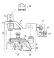
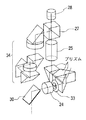
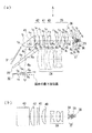
図4は本実施例にかかる実体顕微鏡の概略構成を示す光軸に沿う断面図である(側面方向から見た状態)。本実施例の実体顕微鏡は、鏡体21と、鏡筒光学系22と、接眼光学系23とにより構成されている。鏡体21は、焦点位置を変えるための可変焦点距離の対物光学系24と物体の観察倍率を変えるためのアフォーカルズーム光学系25とを含む観察光学系、及び照明光学系26を備えている。又、前記観察光学系中のアフォーカルズーム光学系25の後側には光路分割プリズム27が配置されており、これにより観察光学系から光路を分割することができ、更に撮影光学系28を備えることにより顕微鏡像の撮影が可能になる。尚、この撮影光学系28は立体視用TVカメラ29と交換可能になっている。
【0032】
更に、鏡体21内において、前記観察光学系の光軸と照明光学系26の光軸とが交わる位置には、これらの光軸を物体面上において一致させるためのハーフミラー30が設けられ、更にこのハーフミラー30の近傍には、ゴースト,フレアの発生を防止するための光吸収フィルター31が設けられている。又、鏡体21の底面部にはカバーガラス32が設けられている。
【0033】
図5は図4に示した実体顕微鏡の観察光学系の詳細な構成を示す図である。この観察光学系では、図示しない物体からの光束は、前記カバーガラス32を経て光路合成手段であるハーフミラー30で反射され、可変焦点距離の対物光学系24及び立体感補正絞り33を介して、その後側に配置されているアフォーカルズーム光学系25へ導かれる。アフォーカルズーム光学系25を経た光束は、光路分割プリズム27にて目視観察光路と撮影観察光路とに分割される。光路分割プリズム27で反射された光束は、その後側に配置されているアフォーカルリレー系34へ導かれる。アフォーカルリレー系34は、その内部で実像を形成し、その後平行光として射出する作用を有している。アフォーカルリレー系34を経た光束は、その後側に配置されている前記観察鏡筒23を介することによって、立体像として観察される。又、光路分割プリズム27を透過した光束は、撮影光学系28へ導かれ、顕微鏡像の撮影がなされる。
【0034】
図6(a)は照明光学系26の構成を示す光軸に沿う断面図である。図6(b)は同図(a)の矢印Aの方向に見た図である。
照明光学系26は、図示しない光源からの光を伝達するライトガイドファイバー35,明るさ絞り36,集光光学系37,照野絞り38,ズームレンズ群39,リレーレンズ40,フォーカスレンズ41,リレーレンズ42,及び照明光を観察物体面へ向けるための射出プリズム43が配置されて構成されている。
【0035】
ズームレンズ群39は2枚の正レンズと1枚の負レンズとからなり、光軸に沿って移動し得るように構成されている。又、フォーカスレンズ41は1枚の正レンズからなり、ズームレンズ群39と同様に光軸に沿って移動し得るようになっている。照明光学系26の変倍は、中倍から高倍にかけてはズームレンズ群39では行われずに、照野絞り38の絞り径を変化させることにより行われる。ズームレンズ群39は前記観察光学系の観察倍率を変えるアフォーカルズーム光学系25の変倍と連動して、観察範囲を良好に照明し得る照明範囲とその照度を設定するためのものである。又、フォーカスレンズ41は、前記観察光学系の焦点位置を観察物体面に合わせる前記対物光学系24と連動して、観察物体面に最適な照明光を提供するためのものである。
尚、各光学系を介して、ライトガイドファイバー35の射出端面と射出プリズム43のファイバ端面結像位置とは共役になっている。
【0036】
本実施例の実体顕微鏡では、照明光学系26の下部にハーフミラー30が配置され、照明光学系26から射出された照明光を図示しない観察物体面へ導き、この観察物体からの観察光を対物光学系24へ導くことができるようになっている。又、ハーフミラー30の近傍に設けられている光吸収フィルター31は、ハーフミラー30によって反射された照明光学系26からの光がゴースト光となって観察光学系へ侵入するのを防止するためのものである。光吸収フィルター31の表面はマルチコート処理がなされており、可視域の光線を吸収できるようになっている。更に、光の透過率を10%以下に抑えるとフレアー除去にも有効である。
【0037】
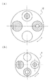
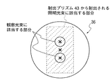
本実施例の実体顕微鏡では、焦点距離を調整する対物光学系24を構成する各レンズ群の移動により、左右の観察光束の間隔及び各光束径の大きさが変化する。例えば、図7は、ハーフミラー30の位置における視野中心に相当する物体位置へ至る観察光束,撮影系及び照明光束の範囲を示す図であり、(a)は低倍時,(b)は中倍時,(c)は高倍時の状態を夫々を示すものである。ここに示すように、観察倍率が高くなる程各光束径が大きくなると共に左右の観察光束の間隔が拡がってしまい、照明範囲から逸脱してしまうことになる。そこで、本実施例の実体顕微鏡では、前記対物光学系24の後側に立体感補正絞り33を配置することにより、高倍時に左右の観察光束の間隔が拡がる特性に鑑み、高倍時の太くなる左右の観察光束の外側を遮ることで立体感の増大を押さえ込むようにした。よって、図7(c)に示されているように、高倍時には左右の観察光束の外側が削れて半月状になる。このことも、無影照明を維持しながらも、必要以上に射出プリズム43の開口部を大きくせず、鏡体21をよりコンパクトにするための効果を生じさせている。
【0038】
更に、本実施例の実体顕微鏡では、前記対物光学系24の焦点位置調節により各光束の位置が移動する場合にも、常に無影照明と、十分な明るさを供給可能とするめに、観察系の光束と照明系の光束との関係が設定されている。このため、常に観察系で観察可能な部分には照明光が届いているため、影を生じることなく観察できる。
【0039】
但し、大きな照明光束径を確保するためには、照明光学系26内の射出プリズム43の開口を大きくする必要があり、顕微鏡全体のコンパクト化に逆行する。そこで、特にコンパクト化の強い要望のある鏡体21の縦方向の長さを最小限に止め、且つ全体的なコンパクト化を達成するために、ライトガイドファイバー35の射出端形状を長方形にすると共に、射出プリズム43の開口をライトガイドファイバー35の射出端面と相似形の長方形とし、その長手方向を主側の観察者の左右方向に相当するように配置した。これにより、主側観察者に対して無影照明を供給しながらも顕微鏡全体の小型化を実現した。
尚、本実施例の実体顕微鏡では、照明開口の大きさは射出プリズム43の開口の大きさ及び射出プリズム43と共役な位置にあるライトガイドファイバー35の射出端面の大きさによって定まる。
【0040】
一方、撮影光学系28の光軸は、対物光学系24の光軸上に設けられている。このようにすることで、撮影光学系28へ導かれる光束にも常に照明光が含まれるので、影のない観察像が得られる。又、前述のように、撮影光学系28は、立体視用TVカメラ29と付け替え可能となっている。よって、この立体視用TVカメラ29の左右の撮影光軸を観察光学系の観察光軸と一致させることで観察光学系で得られるものと同様の立体的な像を撮像できる。この場合も、立体視用TVカメラ29において影のない画像が得られることは云うまでもない。
又、立体視TVカメラ29は光軸を中心として回転可能に取り付けることができるため、その内部の撮像素子を試料に対して垂直な面内であれば自由に配置することができる。従って、立体視TVカメラ29を、主側の観察方向と同方向に配置することができるし、又主側の観察方向に対して直角な方向に配置することもできる。
【0041】
更に、照明光学系26に備えられている明るさ絞り36及び照野絞り38は着脱可能に構成されているが、以下これらの絞り形状とそれに対する照明効果について図8乃至14に基づき説明する。尚、図中の斜線部は遮光部を示している。
【0042】
図8は、通常使用される明るさ絞り36の構成を示す図である。この明るさ絞り36の形状は遮光部がなく基本となるものある。ここには射出プリズム43の開口の大きさによって照明光束径の大きさが決定される様子が示されている。
【0043】
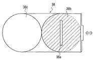
図9は、眼科分野において必須とされる照明方式を実現するための明るさ絞36の構成を示す図である。ここに示された明るさ絞り36は、前記対物光学系24の光軸に対して、傾いた照明と同軸な照明とを切替えるためのものである。この明るさ絞り36は、四角開口絞り44と移動絞り45とからなっている。四角開口絞り44は、射出プリズム43からの照明光束の一部を遮光し得るように中央に細長い四角開口部44aが形成されている。一方、移動絞り45は、中央に円形開口部45aを有している。従って、この移動絞り45を四角開口絞り44と組み合わせることにより,円形開口部45a以外を通過する光束を遮光することができる。しかも、移動絞り45の円形開口部45aを四角開口絞り44の四角開口44aに沿って図の矢印方向に移動させることで、円形開口部45aの位置を前記対物光学系24の光軸に対して外れた位置から同軸の位置まで連続的に変化させることができる。又、四角開口絞り44は、移動絞り45の移動量を小さくし、移動絞り45をコンパクトにする役割も有している。
このように構成された明るさ絞り36を本実施例の実体顕微鏡の照明光学系26に装着することで、眼科で必須とされる照明方式が実現できる。しかも、かかる明るさ絞り36は単純な2枚構成であり、操作性も申し分ない。
【0044】
図10は、中心部に開口が形成された明るさ絞り36の構成を示す図である。ここに示すように、中心部以外の部分を通過する照明光を遮光する場合、前記ハーフミラー30と観察物体面との間では観察系の光束と重なる部分の照明光束は遮光されてしまうが、観察物体面の必要な部分に照明光が供給されれば観察に支障はないため、何ら問題がない。更に、この明るさ絞り36を用いれば、必要な明るさを確保すべく、開口形状を自由に設定できる点有利である。
【0045】
図11は、中心部に遮光部を有し、この遮光部の周辺に開口部が形成された明るさ絞り36の構成を示す図である。このような明るさ絞り36を用いる照明方式は、従来は行われておらず、より立体感のある観察像が得られる照明を実現できる。
【0046】
図12は、観察物体面に対する照明角度を限定し、しかも照明角度を連続的に変化させる場合の明るさ絞り36の構成が示されている。この明るさ絞り36は細長い開口形状を有しており、図の矢印方向に移動させることが可能になっている。このように構成された明るさ絞り36を、眼内観察等の照明角度を変えて行われる観察に用いる場合、観察物体内の内部散乱の影響を考慮しながら観察できるといった従来なかった照明効果が得られる。
【0047】
図13は、通常の観察に用いられる照野絞り38の構成を示す図である。この照野絞り38は顕微鏡の観察光学系の倍率と同期させて高倍観察時に絞り込むことが可能な構成になっている。
【0048】
図14は、一般的な照明を行う場合とスリット照明を行う場合との開口形状が切替え可能な照野絞り38の構成を示す図である。この照野絞り38は、図の矢印方向に移動させることにより、中央部に細長い開口38aが形成された絞り38bと全く遮光部のない絞り38cとの切替えが可能になっている。特に、開口38aを有する絞り38bを図12に示した明るさ絞りと共に用いることにより、良好なスリット照明を供給できる。
これにより、従来外付けのスリットランプを用いずとも、絞りの操作のみにより眼科分野で用いられるスリットランプと同等の照明を実現できる。
【0049】
以下、本実施例の実体顕微鏡の照明光学系26を構成する各光学部材等の数値データを示す。
【0050】
ライトガイドファイバー35の射出端面 3.27mm×5.42mm
ライトガイドファイバー35の開口数 0.66
射出プリズム43の開口 30mm×51mm
【0051】
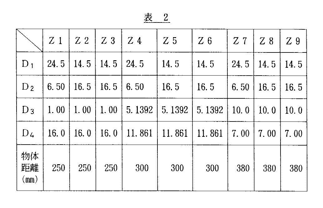
以下、変倍と各移動レンズとの関係について表1,2に示す。
【0058】
第3実施例
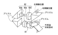
図15は、本実施例にかかる実体顕微鏡の観察光学系の概略構成を示す光軸に沿う断面図である。本実施例では、図5に示された第2実施例の実体顕微鏡の観察光学系とアフォーカルリレー系34の最終レンズまでの構成は同様であるため、ここでは省略されている。又、目視観察における主側,副側に自由度をもたせるため、複数のプリズムが配置されている。
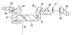
本実施例の実体顕微鏡の観察光学系は、アフォーカルリレー系34の後側に光路分割プリズム51が配置されている。分割された一方の光路には、プリズム52を介して接眼光学系を備えた主側観察鏡筒53が設けられている。又、分割されたもう一方の光路には、プリズム54,プリズム55,イメージローテーター56及び楔型プリズム57を介して接眼光学系を備えた副側観察鏡筒58が設けられている。このようにして、シングルズーム型光学系を実現している。
【0061】
本実施例の実体顕微鏡では、観察光学系の主側観察鏡筒53を矢印59で示される方向に±30°回転させることができる自由度を有している。このため、主側でもかかる回転の自由度を利用して、観察者が観察しやすいように主側観察鏡筒53を回転させてセッティングすることが可能である。更に、主側観察鏡筒53は図の上下方向に180°回転して反転状態にもできる構成となっているため、観察者の眼の位置を反転に伴い上下方向に移動可能で、観察者がより楽な姿勢で観察できるような状態に設定できる。
【0062】
一方、副側観察鏡筒58も矢印60で示すように±30°の範囲で回転可能であるうえ、傾きを変えることが可能になっている。このため、副側で立体視観察できることに加えてより楽な姿勢での観察を可能にしている。更に、副側の観察系において、プリズム54に対してプリズム55以降が矢印61で示される方向に±180°回転可能であり、又、プリズム55に対してイメージローテーター56以降が矢印62で示される方向に±180°回転可能になっている。
【0063】
この構成において、副側の観察系は、矢印60で示される方向への副側観察鏡筒58の回転に応じて、イメージローテーター56が副側観察鏡筒58の回転角度の半分の角度で回転し、正立像を得ることができる。又、楔型プリズム57は、イメージローテーター56のピラミダル加工のエラーによって生じる像の位置移動を補正するために設けられたものである。楔型プリズム57を回転させて補正量を最適に調整した後、イメージローテーター56又はイメージローテーター56と楔型プリズム57とを一体的に移動させることにより、像位置の移動を補正することができる。
【0064】
図16乃至24は、本実施例の実体顕微鏡の観察光学系の構成を示す光軸に沿う断面図である。ここでは、主側観察系を示している。アフォーカルリレー系34以降に配置された各プリズムの構成以外は同様であるため、副側観察系は省略した。図16乃至18は低倍、図19乃至21は中倍、図22乃至24は高倍の状態を夫々示している。
尚、これらのうち、図16,19,22に示された状態の作動距離(Working Distance:以下、WDと称する)は、221.2mm、図17,20,23に示された状態のWDは291.6mm、図18,21,24に示された状態のWDは351.9mmである。又、WDは、カバーガラス32から物体側に6.375mm離れた位置を仮想の物体位置とし、かかる物体位置を基準に測定したものである。
【0065】
図16乃至24に示すように、本実施例の実体顕微鏡では、観察光学系は、図示しない物体側から順に、カバーガラス32,可変焦点距離の対物光学系24,アフォーカルズーム光学系25,アフォーカルリレー系34,光路分割プリズム51,プリズム52,及び主側観察鏡筒53が配置されている。主側観察鏡筒53内には明るさ絞り53aが設けられている。尚、カバーガラス32と対物光学系24との間には図示しない観察物体面上において前記観察光学系と後述する照明光学系の光軸を一致させるためのハーフミラー30が配置されている。又、アフォーカルズーム光学系25の前後には複数のプリズムが配置されている。
【0066】
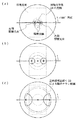
図25(a)は本実施例の実体顕微鏡に配置される照明光学系の構成を示す光軸に沿う断面図である。図25(b)は同図(a)を矢印B方向に見た図である。この照明光学系の構成は第2実施例とほぼ同様であるが、集光光学系37を2枚のレンズで構成した上、照明光学系の各レンズを固定とし、又、図26(a),(b)に示すように、明るさ絞り61及び照野絞り62が夫々数種類ターレット上に配設され、このターレットを回転させることにより異なる絞り形状のものを交換可能にした点が相違する。尚、同図、斜線部は何れも遮光部を示している。
【0067】
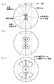
本実施例の実体顕微鏡では、前述のような観察光学系の主側,副側の自由度により、観察系の光束位置が変化する。この様子を図27乃至30に示す。図27乃至30は、本実施例の実体顕微鏡の観察光学系と照明光学系との光路を合成するハーフミラー30の位置における視野中心に相当する物体位置へ至る観察光束及び照明光束の範囲を示す図であり、何れも(a)は低倍時,(b)は中倍時,(c)は高倍時の状態を示している。尚、図27は主側の通常の観察状態、図28は主側観察鏡筒53を±30°回転させた状態の様子を示すものである。又、図29は副側の通常の観察状態、図30は副側観察鏡筒53を±30°回転させた状態の様子を示すものである。
【0068】
本実施例の実体顕微鏡では、前述した観察光学系の主側,副側の自由度に対しても常に十分な明るさを備えた無影照明を供給することを目的としている。そこで、本実施例の実体顕微鏡では、可変焦点距離の対物光学系24の移動による観察光束の位置の移動,アフォーカルズーム光学系25による光束径の大きさの変化,観察系の左右の光軸間隔の変化,及び主側の回転による光束位置の移動,副側の回転,傾きの変化を考慮して、前記目的が達成できるように観察光束と照明光束との関係が設定される。
【0069】
ところで、本実施例の実体顕微鏡の場合、観察光学系の主側の回転に対して、低倍時では、常に観察光束を含むように照明光束径の大きさが設定されているが、高倍時には、観察光束の一部を含むように照明光束の大きさが設定される。
なぜなら、常に観察光束を全てを含むように照明光束径の大きさを設定すると、照明系内の射出プリズム43を大きくする必要があり、コンパクト化に逆行するからである。そこで、本実施例では、顕微鏡鏡体の縦方向の長さを最小限にし、且つ、全体をコンパクトにまとめるために、ライトガイドファイバー35の射出端面形状を長方形にすると共に、射出プリズム43の開口形状をライトガイドファイバー35の射出端面と相似形の長方形とし、その長手方向を主側観察者の左右方向と平行な位置に配置したことで、主側の観察光束に対して優先的に無影照明を供給することができる。
又、副側の観察光学系の位置的な自由度に対しても、その自由度の範囲で、観察光束の一部に照明光束が常に含まれるように射出プリズム43の開口形状が形成されている。
尚、本実施例では、照明開口の大きさは射出プリズム43の開口の大きさにより定まる。
【0070】
更に、本実施例の実体顕微鏡においても、撮影光学系の設置が可能となっている。このとき、撮影光学系は、その光軸が対物光学系24の光軸と一致するように配置される。又、照明光学系の光軸はハーフミラー30により対物レンズ系24の光軸と観察物体面上において一致させている。
【0071】
又、撮影光学系は、第2実施例に示したものと同様に、立体視用のTVカメラと交換可能で、左右の観察光軸の間隔を、観察光学系の光軸間隔と一致させると、良好な立体像を観察できる。
【0072】
以下、本実施例の実体顕微鏡に配置される観察光学系を構成する各光学部材等の数値データを示す。
【0073】
ズーム比 4倍
主側観察鏡筒53及び副側観察鏡筒59の左右光軸間隔 21mm
明るさ絞り53aの口径 9mm φ
【0074】
以下、変倍と各移動レンズとの関係を表3,4に示す。
【0091】
以下、本実施例の実体顕微鏡の照明光学系を構成する各光学部材等の数値データを示す。
【0094】
ライトガイドファイバー35の射出端面 3.27mm×5.42mm
ライトガイドファイバー35の開口数 0.66
射出プリズム43の開口 30mm×51mm
結像位置 カバーガラス32から221mm の位置
照明光学系の焦点距離 -131.791
【0095】
尚、前述した各実施例の数値データにおいて、r1 ,r2 ,・・・・は各レンズ面等の曲率半径、D1 ,d1 ,・・・・は各レンズ等の肉厚又はそれらの間隔、n1 ,n2 ,・・・・は各レンズ等の屈折率、ν1 ,ν2 ,・・・・は各レンズ等のアッベ数を示している。
【0101】
以上説明したように、本発明による実体顕微鏡は、特許請求の範囲に記載された特徴と併せ、以下(1)〜(6)に示すような特徴も備えている。
【0102】
(1)前記第1の結像光学系の光軸と前記照明光学系の光軸とを略一致させていることを特徴とする請求項1に記載の実体顕微鏡。
【0103】
(2)2組以上の左右の立体観察光学系が備えられていることを特徴とする請求項1に記載の実体顕微鏡。
【0104】
(3)前記アフォーカルズーム光学系の光軸上に撮影光学系の光軸を配置したことを特徴とする請求項1に記載の実体顕微鏡。
【0105】
(4)前記第1の結像光学系は変倍機能を有することを特徴とする請求項1に記載の実体顕微鏡。
【0106】
(5)前記第1の結像光学系は対物レンズとアフォーカルズーム光学系とを備えていることを特徴とする請求項1に記載の実体顕微鏡。
【0107】
(6)略平行なスリット状の光束を生じるために、前記明るさ絞りと前記照野絞りとが共にスリット状に変化し得るようにしたことを特徴とする請求項3に記載の実体顕微鏡。
【0108】
【発明の効果】
上述のように、本発明によれば、シングルズーム型光学系において、対物光学系の光軸と同軸な照明と対物光学系の光軸に対して傾いた照明との切り替えが可能であると共に、無影照明を実現できる。又、スリット照明をはじめとした様々な照明効果が得られる。
【図面の簡単な説明】
【図1】第1実施例にかかる実体顕微鏡の構成を示す光軸に沿う断面図である。
【図2】図1に示されたハーフミラー13の位置における視野中心に相当する物体位置へ至る観察光束,撮影光束及び照明光束の範囲を示す図であり、(a)は低倍時,(b)は中倍時,(c)は高倍時の状態を示している。
【図3】(a)はターレット上に設けられた明るさ絞り12の形状の一例を示す図である。(b)はターレット上に設けられた照野絞り9の形状の一例を示す図である。
【図4】第2実施例にかかる実体顕微鏡の概略構成を示す光軸に沿う断面図である。
【図5】図4に示された実体顕微鏡の観察光学系の詳細な構成を示す図である。
【図6】(a)は図4に示された照明光学系26の構成を示す光軸に沿う断面図である。(b)は(a)を矢印Aの方向に見た図である。
【図7】図4に示されたハーフミラー30の位置における視野中心に相当する物体位置へ至る観察光束,撮影系及び照明光束の範囲を示す図であり、(a)は低倍時,(b)は中倍時,(c)は高倍時の状態を夫々を示している。
【図8】第2実施例の実体顕微鏡における照明光学系26に用いられる明るさ絞り36の構成を示す図である。
【図9】第2実施例の実体顕微鏡における照明光学系26に用いられる明るさ絞り36の構成を示す図である。
【図10】第2実施例の実体顕微鏡における照明光学系26に用いられる明るさ絞り36の構成を示す図である。
【図11】第2実施例の実体顕微鏡における照明光学系26に用いられる明るさ絞り36の構成を示す図である。
【図12】第2実施例の実体顕微鏡における照明光学系26に用いられる明るさ絞り36の構成を示す図である。
【図13】第2実施例の実体顕微鏡における照明光学系26に用いられる照野絞り38の構成を示す図である。
【図14】第2実施例の実体顕微鏡における照明光学系26に用いられる照野絞り38の構成を示す図である。
【図15】第3実施例にかかる実体顕微鏡の観察光学系の概略構成を示す光軸に沿う断面図である。
【図16】第3実施例の実体顕微鏡の観察光学系の構成を示す光軸に沿う断面図である。
【図17】第3実施例の実体顕微鏡の観察光学系の構成を示す光軸に沿う断面図である。
【図18】第3実施例の実体顕微鏡の観察光学系の構成を示す光軸に沿う断面図である。
【図19】第3実施例の実体顕微鏡の観察光学系の構成を示す光軸に沿う断面図である。
【図20】第3実施例の実体顕微鏡の観察光学系の構成を示す光軸に沿う断面図である。
【図21】第3実施例の実体顕微鏡の観察光学系の構成を示す光軸に沿う断面図である。
【図22】第3実施例の実体顕微鏡の観察光学系の構成を示す光軸に沿う断面図である。
【図23】第3実施例の実体顕微鏡の観察光学系の構成を示す光軸に沿う断面図である。
【図24】第3実施例の実体顕微鏡の観察光学系の構成を示す光軸に沿う断面図である。
【図25】(a)は第3実施例の実体顕微鏡における照明光学系の構成を示す光軸に沿う断面図である。(b)は(a)を矢印Bの方向に見た図である。
【図26】(a)は第3実施例の実体顕微鏡の照明光学系に配置される明るさ絞り61の構成を示す図である。(b)は第3実施例の実体顕微鏡の照明光学系に配置される照野絞り62の構成を示す図である。
【図27】図25(a)に示されたハーフミラー30の位置における視野中心に相当する物体位置へ至る観察光束及び照明光束の範囲を示す図であり、(a)は低倍時,(b)は中倍時,(c)は高倍時の状態を示している。
【図28】図25(a)に示されたハーフミラー30の位置における視野中心に相当する物体位置へ至る観察光束及び照明光束の範囲を示す図であり、(a)は低倍時,(b)は中倍時,(c)は高倍時の状態を示している。
【図29】図25(a)に示されたハーフミラー30の位置における視野中心に相当する物体位置へ至る観察光束及び照明光束の範囲を示す図であり、(a)は低倍時,(b)は中倍時,(c)は高倍時の状態を示している。
【図30】図25(a)に示されたハーフミラー30の位置における視野中心に相当する物体位置へ至る観察光束及び照明光束の範囲を示す図であり、(a)は低倍時,(b)は中倍時,(c)は高倍時の状態を示している。
【図31】従来の手術用顕微鏡の構成を示す部分側面断面図である。
【図32】従来の手術用顕微鏡の構成を示す図である。
【図33】図31に示された手術用顕微鏡における照明方式を説明するための図である。
【図34】一般的な手術用顕微鏡における同軸照明の構成を示す図である。
【図35】(a),(b)は図34に示された同軸照明により生じる不具合を説明するための図である。
【符号の説明】
1,71,81 対物レンズ
2,25 アフォーカルズーム光学系
2a,82a 第1レンズ群
2b,82b 第2レンズ群
2c,82c 第3レンズ群
3 観察鏡筒
4,5,10 ミラー
6 TVカメラ
7,35,75 ライトガイドファイバー
8,11 レンズ
9,38 照野絞り
12,36,53a 明るさ絞り
13,30 ハーフミラー
21 鏡体
22 鏡筒光学系
23 接眼光学系
24 対物光学系
26 照明光学系
27,51 光路分割プリズム
28 撮影光学系
29 立体視用TVカメラ
31 光吸収フィルター
32 カバーガラス
33 立体感補正絞り
34 アフォーカルリレー系
37 集光光学系
39 ズームレンズ群
40,42 リレーレンズ
41 フォーカスレンズ
43 射出プリズム
44 四角開口絞り
44a 四角開口部
45 移動絞り
45a 円形開口部
52,54,55 プリズム
53 主側観察鏡筒
56 イメージローテーター
57 楔型プリズム
58 副側観察鏡筒
59,60,61,62 矢印
72,73,74 光学成分
76,77 レンズ系
78 偏向部材
82 変倍光学系[0001]
BACKGROUND OF THE INVENTION
The present invention relates to an illumination system for a stereomicroscope, and more particularly to illumination for a surgical microscope.
[0002]
[Prior art]
In recent years, surgery using a surgical microscope has become widespread in the medical field. In particular, recently, in order to minimize the burden on patients, the development of surgical machines and surgical techniques has been progressing. Accordingly, it is necessary for a plurality of people to work while observing the microscope image for a long time from a free direction. However, the surgical microscopes that are widely used at present are desired to be improved because the observation method itself is limited.
[0003]
Therefore, in order to meet such a demand, a new observation system method (hereinafter referred to as a single zoom type optical system) is proposed by German Published Patent No. 19541237A1 and Japanese Patent Laid-Open No. 6-337351.
[0004]
FIG. 31 is a partial side cross-sectional view showing the configuration of the surgical microscope proposed in German Published Patent No. 19541237A1. In this surgical microscope, the first to third three
[0005]
FIG. 32 is a diagram showing a configuration of a stereomicroscope disclosed in Japanese Patent Laid-Open No. 6-337351. This stereomicroscope includes an
[0006]
Here, the single zoom type optical system is referred to as “comprising an optical system having a zoom function and sharing one optical axis, and taking out a stereoscopic observation light beam in order to form left and right images from the light beam emitted from this optical system. It is defined as an “observation system having left and right apertures and an optical system that forms an image for visual observation or photographing of light beams extracted from the left and right apertures”. The main feature of this optical system is that it is a zoom type optical system that is common to the left and right, so that stereoscopic observation from multiple directions is possible at the same time. This is possible with the optical system shown in FIGS.
[0007]
[Problems to be solved by the invention]
In order to perform observation with a visual observation or an imaging system, a surgical microscope needs to include an illumination system that illuminates the observation area with illumination light to illuminate the observation range brightly and uniformly. However, not only that, for example, (1) improvement of the illumination method itself, (2) improvement of the complexity of operation of the illumination device during the operation, (3) improvement of complicated work when replacing the illumination device, (4) ▼ Flexible lighting effects depending on the surgical content and field are desired.
However, the illumination system used in the conventional single zoom optical system including the microscopes shown in FIGS. 31 and 32 uses the conventional illumination system as it is or simply combines them. The demands required for the illumination system as in the above (1) to (4) cannot be satisfied.
[0008]
In the field of neurosurgery, a small hole is made in the head, and an internal operation is performed through this hole. At this time, I would like to observe without producing a shadow in observing the bottom or side of the hole. In addition, there is a demand to observe without producing a shadow if it is a site that can be observed with an observation system even if some blood vessels, nerves, etc. are in the observation visual field.
However, in the conventional single-zoom surgical microscope shown in FIG. 31, an illumination
[0009]
Further, the single zoom type surgical microscope disclosed in Japanese Patent Laid-Open No. 6-337351 cannot satisfy the above-mentioned demand because it does not show specific contents regarding the illumination system.
[0010]
FIG. 34 is a view as seen from the objective lens side of a surgical microscope that realizes coaxial illumination by providing an exit surface of an illumination prism at a position coaxial with the optical axis of a generally known objective lens. FIGS. 35 (a) and 35 (b) are side views of FIG. 34, as seen from directions different from each other by 90 °. FIG. 35 shows a state where a minute cylindrical obstacle such as a blood vessel exists so as to cross the optical axis of the objective lens. In the surgical microscope shown here, as shown in FIGS. 35A and 35B, the observation light beam reaches the bottom surface of the hole, so that the bottom surface can be observed even if there is an obstacle, but the illumination light beam is It will be blocked by obstacles and will not reach the bottom, and will be shadowed by obstacles.
[0011]
As described above, the conventional single-zoom surgical microscope cannot realize shadowless illumination.
[0012]
In addition, in surgical microscopes used in the ophthalmic field, the illumination system irradiates illumination light that is coaxial with the optical axis of the objective lens for observation of the fundus reflection light, and observation is performed while avoiding retinal damage due to illumination light. In addition, it is necessary to switch to the oblique illumination method in which the illumination light is tilted with respect to the optical axis of the objective lens. Moreover, it is preferable that the switching can be easily performed.
In ophthalmology, eye inspection is performed using slit-shaped parallel light called a slit lamp. However, the slit lamp is an external illumination device and is a hindrance during normal observation. It is possible to attach to and detach from. However, this operation is complicated, and there is a demand for a compact and integrated operation.
[0013]
Furthermore, an illumination pattern suitable for surgery including brain surgery, ophthalmology, etc. is desired. However, the conventional illumination pattern is difficult to realize because there is no degree of freedom in illumination. For example, it does not meet demands such as observing while switching between observation in which the stereoscopic effect of an observation object is enhanced by illumination light composed only of components inclined with respect to the objective optical axis and normal observation.
[0014]
Therefore, in view of the problems of the prior art, the present invention has the following objects.
[0015]
The first object of the present invention is to enable stereoscopic observation by a plurality of persons at the same time, to ensure the degree of freedom of observation positions on the main side and the sub side, and to illuminate the surgical site in normal observation brightly and uniformly. A surgical microscope with a mold optical system is provided.
The second object is to provide a surgical microscope capable of always supplying shadowless illumination to a site that can be observed with an observation system even if there are some obstacles in the field of brain surgery. Specifically, in a single-zoom optical system, it can supply bright illumination light without causing shadows due to changes in the observation beam interval and beam diameter due to zooming, and changes in the observation beam optical axis interval due to focusing. To provide a microscope. In addition, a surgical microscope that can supply bright illumination light without shadows even when the rotation direction of the observation optical axis is moved due to changes in the observation position on the main side, the posture of the observer, or changes in the observation position on the secondary side Is to provide.
[0016]
The third object is to switch between an illumination system that is coaxial with the optical axis of the objective lens required in the ophthalmic field and an oblique illumination system that is tilted with respect to the optical axis of the objective lens. It is to provide a surgical microscope having a system.
The fourth object is to switch between an illumination method for illuminating a slit-like parallel light beam inclined with respect to the optical axis of an objective lens required in the ophthalmic field by changing an inclination angle or a projection position and each of the illumination methods. And it is providing the surgical microscope which has an illumination system of a simple structure.
A fifth object is to provide a surgical microscope that can realize illumination combined with illumination effects that could not be realized with a conventional microscope and that can easily switch between illumination effects.
[0017]
[Means for Solving the Problems]
In order to achieve the above object, a stereomicroscope according to the present invention has a light source, an illumination optical system for irradiating the object surface with light from the light source, and at least an imaging performance for forming an image of the object surface. 1 imaging optical system, left and right openings for forming left and right images disposed on the exit side of the first imaging optical system, and a second imaging optical system for viewing or photographing the left and right images A stereomicroscope having an optical path synthesizing unit for synthesizing optical paths of the illumination optical system and the observation optical system.The illumination optical system is provided with an aperture stop for changing the illumination angle of illumination light,The illumination light beam from the illumination optical system is always included in at least a part of the observation light beam that reaches the center of the observation field of the observation optical system.
[0018]
The stereomicroscope of the present invention isThe aperture stop can be replaced with a slit shape.
The stereomicroscope of the present invention includes the illumination optical system,The illumination field stop which makes the shape of an illumination range variable is provided.
The stereomicroscope of the present invention is characterized in that the illumination field stop can be replaced with a slit shape.
The stereomicroscope of the present invention is characterized in that the optical axis of the first imaging optical system and the optical axis of the illumination optical system are substantially matched.
In addition, the stereomicroscope according to the present invention includes two or more sets of left and right stereoscopic observation optical systems.
The stereomicroscope of the present invention is characterized in that the first imaging optical system has a zooming function.
In the stereomicroscope of the present invention, the first imaging optical system includes an objective lens and an afocal zoom optical system.
The stereomicroscope of the present invention is characterized in that the optical axis of the photographing optical system is arranged on the optical path of the first imaging optical system.
Furthermore, the stereomicroscope of the present invention is:The brightness stop has a light shielding portion at the center.
[0019]
DETAILED DESCRIPTION OF THE INVENTION
Hereinafter, the present invention will be described in detail based on illustrated embodiments.
[0020]
First embodiment
FIG. 1 is a cross-sectional view along the optical axis showing the configuration of the stereomicroscope according to the present embodiment.
In the stereomicroscope of the present embodiment, an observation optical system is constituted by a fixed-
The
[0021]
In the stereomicroscope of the present embodiment, the
Furthermore, in the present embodiment, the
[0022]
On the other hand, the illumination optical system includes a light guide fiber 7, a
[0023]
The light emitted from the light guide fiber 7 is formed by the
[0024]
By the way, when adopting a configuration having a focusing function such as an objective lens having a variable focal position, the setting is made in consideration of changes in the interval of the observation light beam and the size of the light beam diameter.
In this way, illumination light is always guided to an object position that can be observed with the observation optical system, so that observation can be performed without shadow. Moreover, in addition to being able to illuminate brightly by forming a large illumination opening in advance, various forms of illumination methods can be easily realized by shielding part of the illumination light beam.
Here, the illumination light beam means the size of the illumination light beam diameter that determines the angle formed by the optical axis of the objective lens 1 (first imaging optical system) of the illumination light condensed at the center of the field of view. .
[0025]
FIG. 2 shows the ranges of the observation light beam, the photographing light beam, and the illumination light beam that reach the object position corresponding to the center of the visual field at the position of the
At low magnification, the observation beam is thin and the distance between the left and right observation optical axes is narrow. At high magnification, the observation beam is thick and the distance between the left and right observation optical axes is wide. This relationship is directly proportional to the zoom magnification of the afocal zoom
[0026]
By the way, what is important in observation with a stereomicroscope is the center of the visual field, and in particular, the angle of view of the surgical microscope is narrowly replaced by the appearance of the center of the visual field. Therefore, as shown in FIGS. 2A to 2C, the relationship between the exit light flux of the illumination system and the position of the observation light flux reaching the center of the field of view may be considered.
In order to realize illumination with no shadow for the observation optical system, it is necessary that part of the left and right observation light beams always include a component of illumination light. Specifically, it can be realized by configuring the left and right observation light beams and the illumination light beam to intersect.
[0027]
As shown in FIGS. 2A to 2C, when the magnification is low, the distance between the left and right observation light beams is relatively narrow, and the observation light beam itself is thin, so that all the observation light beams are included in the illumination light beam. Shadowless lighting can be realized. At the time of high magnification, the entire observation light beam is not included in the illumination light beam, but at least a part of the observation light beam is included, so that no shadow is formed in the observation system. A circle indicated by a dotted line is an illumination light beam.
In this embodiment, the photographing optical system is disposed at a position away from the optical axis of the
[0028]
FIG. 3A shows an example of the shape of the
The stereomicroscope of the present embodiment is provided with such an
[0029]
FIG.3 (b) is a figure which shows an example of the shape of the illumination field stop 9 provided on the turret. The shaded portion in the figure is a light shielding portion. The illumination field stop 9 is for determining the shape of the illumination range, and the illumination effect can be further enhanced by making the light shielding characteristics variable.
For this reason, for example, if the
[0030]
In the present embodiment, since the illumination field stop 9 and the
[0031]
Second embodiment
FIG. 4 is a cross-sectional view along the optical axis showing a schematic configuration of the stereomicroscope according to the present embodiment (as viewed from the side surface). The stereomicroscope of the present embodiment includes a
[0032]
Furthermore, a
[0033]
FIG. 5 is a diagram showing a detailed configuration of the observation optical system of the stereomicroscope shown in FIG. In this observation optical system, a light beam from an object (not shown) is reflected by the
[0034]
FIG. 6A is a cross-sectional view along the optical axis showing the configuration of the illumination
The illumination
[0035]
The
Note that the exit end face of the
[0036]
In the stereomicroscope of the present embodiment, the
[0037]
In the stereomicroscope of the present embodiment, the distance between the left and right observation light beams and the size of each light beam diameter change due to the movement of each lens group constituting the objective
[0038]
Furthermore, in the stereomicroscope of the present embodiment, even when the position of each light beam is moved by adjusting the focal position of the objective
[0039]
However, in order to ensure a large illumination beam diameter, it is necessary to increase the aperture of the
In the stereomicroscope of the present embodiment, the size of the illumination aperture is determined by the size of the
[0040]
On the other hand, the optical axis of the photographing
In addition, since the
[0041]
Further, the
[0042]
FIG. 8 is a diagram showing a configuration of a normally used
[0043]
FIG. 9 is a diagram showing a configuration of the
By mounting the
[0044]
FIG. 10 is a diagram showing the configuration of the
[0045]
FIG. 11 is a diagram showing a configuration of an
[0046]
FIG. 12 shows the configuration of the
[0047]
FIG. 13 is a diagram showing the configuration of the
[0048]
FIG. 14 is a diagram illustrating a configuration of an
Thus, illumination equivalent to that of a slit lamp used in the ophthalmic field can be realized only by operating the diaphragm without using a conventional externally attached slit lamp.
[0049]
Hereinafter, numerical data of each optical member and the like constituting the illumination
[0050]
Output end face of
Numerical aperture of
Aperture of
[0051]
Tables 1 and 2 show the relationship between zooming and each moving lens.
[0058]
Third embodiment
FIG. 15 is a cross-sectional view along the optical axis showing a schematic configuration of the observation optical system of the stereomicroscope according to the present embodiment. In this embodiment, the configuration of the observation optical system of the stereomicroscope of the second embodiment shown in FIG. 5 and the final lens of the
In the observation optical system of the stereomicroscope of this embodiment, an optical
[0061]
The stereomicroscope of this embodiment has a degree of freedom that allows the main-
[0062]
On the other hand, the
[0063]
In this configuration, in the secondary observation system, the
[0064]
16 to 24 are cross-sectional views along the optical axis showing the configuration of the observation optical system of the stereomicroscope of this embodiment. Here, the main observation system is shown. Since the configuration other than the prisms arranged after the
Of these, the working distance (working distance: hereinafter referred to as WD) shown in FIGS. 16, 19, and 22 is 221.2 mm, and the WD in the state shown in FIGS. The WD in the state shown in FIGS. 18, 21, and 24 is 291.9 mm and 351.9 mm. The WD is a measurement based on the position of the object located 6.375 mm away from the
[0065]
As shown in FIGS. 16 to 24, in the stereomicroscope of the present embodiment, the observation optical system includes a
[0066]
FIG. 25A is a cross-sectional view along the optical axis showing the configuration of the illumination optical system arranged in the stereomicroscope of the present embodiment. FIG. 25B is a diagram when FIG. 25A is viewed in the direction of arrow B. The configuration of this illumination optical system is substantially the same as that of the second embodiment, but the condensing
[0067]
In the stereomicroscope of the present embodiment, the light beam position of the observation system changes depending on the degrees of freedom on the main side and the sub side of the observation optical system as described above. This is shown in FIGS. 27 to 30 show the ranges of the observation light beam and the illumination light beam that reach the object position corresponding to the center of the visual field at the position of the
[0068]
The stereomicroscope of this embodiment is intended to supply shadowless illumination that always has sufficient brightness with respect to the degrees of freedom on the main side and the sub side of the observation optical system described above. Therefore, in the stereomicroscope of the present embodiment, the position of the observation light beam is moved by the movement of the objective
[0069]
By the way, in the case of the stereomicroscope of the present embodiment, the size of the illumination light beam diameter is always set so as to include the observation light beam at low magnification with respect to the rotation of the main side of the observation optical system. The size of the illumination light beam is set so as to include a part of the observation light beam.
This is because if the size of the illumination beam diameter is set so as to always include all of the observation beam, it is necessary to enlarge the
Also, the opening shape of the
In the present embodiment, the size of the illumination aperture is determined by the size of the aperture of the
[0070]
Furthermore, in the stereomicroscope of this embodiment, it is possible to install a photographing optical system. At this time, the photographing optical system is arranged so that its optical axis coincides with the optical axis of the objective
[0071]
Similarly to the one shown in the second embodiment, the photographing optical system can be replaced with a stereoscopic TV camera, and the distance between the left and right observation optical axes is made to coincide with the optical axis distance of the observation optical system. A good stereoscopic image can be observed.
[0072]
Hereinafter, numerical data of each optical member constituting the observation optical system arranged in the stereomicroscope of the present embodiment will be shown.
[0073]
4x zoom ratio
The distance between the left and right optical axes of the
Diameter of the
[0074]
Tables 3 and 4 show the relationship between zooming and each moving lens.
[0091]
Hereinafter, numerical data of each optical member and the like constituting the illumination optical system of the stereomicroscope of the present embodiment will be shown.
[0094]
Output end face of
Numerical aperture of
Aperture of
Image formation position 221mm from
Focal length of illumination optics -131.791
[0095]
In the numerical data of the above-described embodiments, r1, R2, ... is the radius of curvature of each lens surface, etc., D1, D1,... Are the thickness of each lens or the distance between them, n1, N2, ... are the refractive indices of each lens, ν1, Ν2,... Indicate the Abbe number of each lens.
[0101]
As described above, the stereomicroscope according to the present invention has the following features (1) to (6) in addition to the features described in the claims.
[0102]
(1) The stereomicroscope according to
[0103]
(2) The stereomicroscope according to
[0104]
(3) The stereomicroscope according to
[0105]
(4) The stereomicroscope according to
[0106]
(5) The stereomicroscope according to
[0107]
(6) The stereomicroscope according to
[0108]
【The invention's effect】
As described above, according to the present invention, in the single zoom optical system, it is possible to switch between illumination coaxial with the optical axis of the objective optical system and illumination inclined with respect to the optical axis of the objective optical system, Shadowless lighting can be realized. Moreover, various illumination effects including slit illumination can be obtained.
[Brief description of the drawings]
FIG. 1 is a cross-sectional view along the optical axis showing the configuration of a stereomicroscope according to a first embodiment.
2 is a diagram showing ranges of an observation light beam, a photographing light beam, and an illumination light beam that reach an object position corresponding to the center of the visual field at the position of the
FIG. 3A is a diagram showing an example of the shape of an
FIG. 4 is a sectional view taken along an optical axis showing a schematic configuration of a stereomicroscope according to a second embodiment.
5 is a diagram showing a detailed configuration of an observation optical system of the stereomicroscope shown in FIG.
6A is a cross-sectional view along the optical axis showing the configuration of the illumination
7 is a diagram showing ranges of an observation light beam, a photographing system, and an illumination light beam that reach an object position corresponding to the center of the visual field at the position of the
FIG. 8 is a diagram showing a configuration of an aperture stop used in the illumination optical system in the stereomicroscope of the second embodiment.
FIG. 9 is a diagram showing a configuration of an aperture stop used in the illumination optical system in the stereomicroscope of the second embodiment.
FIG. 10 is a diagram showing a configuration of an
FIG. 11 is a diagram showing a configuration of an
12 is a diagram showing a configuration of an
13 is a diagram showing a configuration of an
FIG. 14 is a diagram showing a configuration of an
FIG. 15 is a sectional view taken along an optical axis showing a schematic configuration of an observation optical system of a stereomicroscope according to a third example.
FIG. 16 is a cross-sectional view along the optical axis showing the configuration of the observation optical system of the stereomicroscope of the third example.
FIG. 17 is a cross-sectional view along the optical axis showing the configuration of the observation optical system of the stereomicroscope of the third example.
FIG. 18 is a cross-sectional view along the optical axis showing the configuration of the observation optical system of the stereomicroscope of the third example.
FIG. 19 is a cross-sectional view along the optical axis showing the configuration of the observation optical system of the stereomicroscope of the third example.
FIG. 20 is a cross-sectional view along the optical axis showing the configuration of the observation optical system of the stereomicroscope of the third example.
FIG. 21 is a cross-sectional view along the optical axis showing the configuration of the observation optical system of the stereomicroscope of the third example.
FIG. 22 is a cross-sectional view along the optical axis showing the configuration of the observation optical system of the stereomicroscope of the third example.
FIG. 23 is a cross-sectional view along the optical axis showing the configuration of the observation optical system of the stereomicroscope of the third example.
FIG. 24 is a cross-sectional view along the optical axis showing the configuration of the observation optical system of the stereomicroscope of the third example.
FIG. 25A is a cross-sectional view along the optical axis showing the configuration of the illumination optical system in the stereomicroscope of the third embodiment. (B) is the figure which looked at (a) in the direction of arrow B. FIG.
FIG. 26A is a diagram showing a configuration of an
FIG. 27 is a diagram showing a range of an observation light beam and an illumination light beam reaching an object position corresponding to the center of the visual field at the position of the
FIG. 28 is a diagram showing a range of an observation light beam and an illumination light beam reaching an object position corresponding to the center of the visual field at the position of the
FIG. 29 is a diagram showing a range of an observation light beam and an illumination light beam that reach an object position corresponding to the center of the visual field at the position of the
30 is a diagram showing a range of an observation light beam and an illumination light beam reaching an object position corresponding to the center of the visual field at the position of the
FIG. 31 is a partial side cross-sectional view showing a configuration of a conventional surgical microscope.
FIG. 32 is a diagram showing a configuration of a conventional surgical microscope.
FIG. 33 is a diagram for explaining an illumination method in the surgical microscope shown in FIG. 31;
FIG. 34 is a diagram showing a configuration of coaxial illumination in a general surgical microscope.
FIGS. 35A and 35B are diagrams for explaining a problem caused by the coaxial illumination shown in FIG.
[Explanation of symbols]
1,71,81 Objective lens
2,25 Afocal zoom optical system
2a, 82a First lens group
2b, 82b Second lens group
2c, 82c Third lens group
3 Observation tube
4,5,10 mirror
6 TV camera
7, 35, 75 Light guide fiber
8,11 lens
9,38 Teruno iris
12, 36, 53a Brightness stop
13,30 half mirror
21 Mirror
22 Optical system
23 Eyepiece optical system
24 Objective optical system
26 Illumination optics
27, 51 Optical path splitting prism
28. Imaging optical system
29 Stereoscopic TV camera
31 Light absorption filter
32 Cover glass
33 Stereoscopic correction aperture
34 Afocal relay system
37 Condensing optical system
39 Zoom lens group
40, 42 Relay lens
41 Focus lens
43 Ejection prism
44 square aperture stop
44a Square opening
45 Moving aperture
45a circular opening
52, 54, 55 Prism
53 Main observation tube
56 Image Rotator
57 Wedge prism
58 Secondary observation tube
59, 60, 61, 62 arrows
72, 73, 74 Optical components
76,77 Lens system
78 Deflection member
82 Variable magnification optical system
Claims (10)
前記照明光学系には照明光の照射角度を可変にするための明るさ絞りが備えられており、
前記観察光学系の観察視野中心部へ至る観察光束の少なくとも一部に前記照明光学系からの照明光束が常に含まれるようにしたことを特徴とする実体顕微鏡。A light source, an illumination optical system for irradiating the object plane with light from the light source, a first imaging optical system having at least imaging performance for forming an image of the object plane, and the first imaging An illumination optical system, comprising: left and right apertures for forming left and right images disposed on the exit side of the optical system; and an observation optical system having a second imaging optical system for viewing or photographing the left and right images. In a stereomicroscope having an optical path synthesizing means for synthesizing the optical path with the observation optical system,
The illumination optical system is provided with an aperture stop for changing the illumination angle of illumination light,
A stereomicroscope characterized in that an illumination light beam from the illumination optical system is always included in at least a part of an observation light beam that reaches the center of an observation field of the observation optical system.
Priority Applications (1)
| Application Number | Priority Date | Filing Date | Title |
|---|---|---|---|
| JP26623697A JP3891663B2 (en) | 1997-09-30 | 1997-09-30 | Stereo microscope |
Applications Claiming Priority (1)
| Application Number | Priority Date | Filing Date | Title |
|---|---|---|---|
| JP26623697A JP3891663B2 (en) | 1997-09-30 | 1997-09-30 | Stereo microscope |
Publications (3)
| Publication Number | Publication Date |
|---|---|
| JPH11109254A JPH11109254A (en) | 1999-04-23 |
| JPH11109254A5 JPH11109254A5 (en) | 2005-06-09 |
| JP3891663B2 true JP3891663B2 (en) | 2007-03-14 |
Family
ID=17428168
Family Applications (1)
| Application Number | Title | Priority Date | Filing Date |
|---|---|---|---|
| JP26623697A Expired - Fee Related JP3891663B2 (en) | 1997-09-30 | 1997-09-30 | Stereo microscope |
Country Status (1)
| Country | Link |
|---|---|
| JP (1) | JP3891663B2 (en) |
Families Citing this family (12)
| Publication number | Priority date | Publication date | Assignee | Title |
|---|---|---|---|---|
| DE10144062B4 (en) | 2001-09-07 | 2010-05-27 | Leica Microsystems Ag | Microscope with a lighting reflection |
| JP2006154229A (en) * | 2004-11-29 | 2006-06-15 | Nikon Corp | microscope |
| DE102005018432A1 (en) * | 2005-04-21 | 2006-10-26 | Leica Microsystems (Schweiz) Ag | Optical system e.g. surgical microscope for e.g. neurosurgery, has organic LED displays arranged in immediate visual field of observer and in attachment locations at microscope body, X-Y-coupling, carrier arm and eyepiece tube, respectively |
| DE102006009452B4 (en) * | 2005-10-20 | 2010-07-01 | Carl Zeiss Surgical Gmbh | stereomicroscope |
| JP2007310264A (en) * | 2006-05-22 | 2007-11-29 | Nikon Corp | Zoom microscope |
| JP5209906B2 (en) * | 2007-07-02 | 2013-06-12 | 株式会社目白プレシジョン | Lighting device |
| EP2185953B1 (en) * | 2007-09-03 | 2017-01-11 | Carl Zeiss Meditec AG | Light trap, coupling device for a beam path, lighting device, and optical observation device |
| DE102009028229B3 (en) | 2009-06-10 | 2010-12-09 | Leica Instruments (Singapore) Pte. Ltd. | Illumination device for a surgical microscope |
| DE102010042351B4 (en) * | 2010-10-12 | 2014-02-13 | Leica Microsystems Cms Gmbh | Microscope illumination system, microscope and oblique incident illumination method |
| DE102013226784A1 (en) | 2013-12-19 | 2015-06-25 | Leica Microsysteme (Schweiz) AG | surgical microscope |
| KR102142861B1 (en) * | 2020-05-26 | 2020-08-10 | 주식회사 에프앤디파트너스 | Dermascope device capable of real-time observation and shooting at the same time |
| CN115644795B (en) * | 2022-12-12 | 2024-04-09 | 图湃(北京)医疗科技有限公司 | Surgical microscope system and surgical microscope |
-
1997
- 1997-09-30 JP JP26623697A patent/JP3891663B2/en not_active Expired - Fee Related
Also Published As
| Publication number | Publication date |
|---|---|
| JPH11109254A (en) | 1999-04-23 |
Similar Documents
| Publication | Publication Date | Title |
|---|---|---|
| CN1157153C (en) | Eye viewing device for retinal viewing through undilated pupil | |
| CN102626342B (en) | Illumination device and observation device | |
| JP3377238B2 (en) | Slit lamp microscope | |
| US9055896B2 (en) | Ophthalmoscope for observing an eye | |
| JP4422394B2 (en) | Stereo microscope | |
| US7990610B2 (en) | Stereomicroscope with repositioning assistant's microscope | |
| JP3891663B2 (en) | Stereo microscope | |
| US5020891A (en) | Single aperture confocal scanning biomicroscope and kit for converting single lamp biomicroscope thereto | |
| CN115644795B (en) | Surgical microscope system and surgical microscope | |
| JPH085923A (en) | Stereomicroscope | |
| US6072623A (en) | Slit lamp microscope | |
| JP2004272263A (en) | Illuminating device for microscope | |
| US5099354A (en) | Kit for converting a slit lamp biomicroscope into a single aperture confocal scanning biomicroscope | |
| JP3534733B2 (en) | Fixed high magnification switching microscope | |
| JP7002817B2 (en) | Front lens device and ophthalmic microscope | |
| JPH03128033A (en) | Ophthalmological machinery | |
| WO2019066027A1 (en) | Front-end lens device and ophthalmic microscope | |
| JP2021518183A (en) | Ocular imaging device for imaging the posterior and anterior segment of the eye | |
| JP2019092725A (en) | Front-end lens device and ophthalmic microscope | |
| JP2004109488A (en) | Stereoscopic microscope | |
| JP2019092844A (en) | Front-end lens device and ophthalmic microscope | |
| JP2001340301A (en) | Fundus imaging device | |
| US5652639A (en) | Indirect ophthalmoscope producing an erect stereoscopic image | |
| JP2642416B2 (en) | Simultaneous stereoscopic fundus camera | |
| JPH06142052A (en) | Optometric apparatus |
Legal Events
| Date | Code | Title | Description |
|---|---|---|---|
| A521 | Written amendment |
Free format text: JAPANESE INTERMEDIATE CODE: A523 Effective date: 20040903 |
|
| A621 | Written request for application examination |
Free format text: JAPANESE INTERMEDIATE CODE: A621 Effective date: 20040903 |
|
| A977 | Report on retrieval |
Free format text: JAPANESE INTERMEDIATE CODE: A971007 Effective date: 20060712 |
|
| A131 | Notification of reasons for refusal |
Free format text: JAPANESE INTERMEDIATE CODE: A131 Effective date: 20060725 |
|
| A521 | Written amendment |
Free format text: JAPANESE INTERMEDIATE CODE: A523 Effective date: 20060920 |
|
| TRDD | Decision of grant or rejection written | ||
| A01 | Written decision to grant a patent or to grant a registration (utility model) |
Free format text: JAPANESE INTERMEDIATE CODE: A01 Effective date: 20061128 |
|
| A61 | First payment of annual fees (during grant procedure) |
Free format text: JAPANESE INTERMEDIATE CODE: A61 Effective date: 20061205 |
|
| FPAY | Renewal fee payment (event date is renewal date of database) |
Free format text: PAYMENT UNTIL: 20101215 Year of fee payment: 4 |
|
| FPAY | Renewal fee payment (event date is renewal date of database) |
Free format text: PAYMENT UNTIL: 20111215 Year of fee payment: 5 |
|
| FPAY | Renewal fee payment (event date is renewal date of database) |
Free format text: PAYMENT UNTIL: 20111215 Year of fee payment: 5 |
|
| FPAY | Renewal fee payment (event date is renewal date of database) |
Free format text: PAYMENT UNTIL: 20121215 Year of fee payment: 6 |
|
| LAPS | Cancellation because of no payment of annual fees |