EP1455215A2 - Microscope illuminating apparatus - Google Patents
Microscope illuminating apparatus Download PDFInfo
- Publication number
- EP1455215A2 EP1455215A2 EP04003065A EP04003065A EP1455215A2 EP 1455215 A2 EP1455215 A2 EP 1455215A2 EP 04003065 A EP04003065 A EP 04003065A EP 04003065 A EP04003065 A EP 04003065A EP 1455215 A2 EP1455215 A2 EP 1455215A2
- Authority
- EP
- European Patent Office
- Prior art keywords
- microscope
- deflection
- illumination
- observation
- lighting
- Prior art date
- Legal status (The legal status is an assumption and is not a legal conclusion. Google has not performed a legal analysis and makes no representation as to the accuracy of the status listed.)
- Granted
Links
Images


Classifications
-
- G—PHYSICS
- G02—OPTICS
- G02B—OPTICAL ELEMENTS, SYSTEMS OR APPARATUS
- G02B27/00—Optical systems or apparatus not provided for by any of the groups G02B1/00 - G02B26/00, G02B30/00
- G02B27/10—Beam splitting or combining systems
- G02B27/14—Beam splitting or combining systems operating by reflection only
- G02B27/144—Beam splitting or combining systems operating by reflection only using partially transparent surfaces without spectral selectivity
-
- A—HUMAN NECESSITIES
- A61—MEDICAL OR VETERINARY SCIENCE; HYGIENE
- A61B—DIAGNOSIS; SURGERY; IDENTIFICATION
- A61B3/00—Apparatus for testing the eyes; Instruments for examining the eyes
- A61B3/10—Objective types, i.e. instruments for examining the eyes independent of the patients' perceptions or reactions
- A61B3/13—Ophthalmic microscopes
- A61B3/132—Ophthalmic microscopes in binocular arrangement
-
- G—PHYSICS
- G02—OPTICS
- G02B—OPTICAL ELEMENTS, SYSTEMS OR APPARATUS
- G02B21/00—Microscopes
- G02B21/06—Means for illuminating specimens
- G02B21/08—Condensers
-
- G—PHYSICS
- G02—OPTICS
- G02B—OPTICAL ELEMENTS, SYSTEMS OR APPARATUS
- G02B27/00—Optical systems or apparatus not provided for by any of the groups G02B1/00 - G02B26/00, G02B30/00
- G02B27/10—Beam splitting or combining systems
- G02B27/14—Beam splitting or combining systems operating by reflection only
- G02B27/143—Beam splitting or combining systems operating by reflection only using macroscopically faceted or segmented reflective surfaces
-
- G—PHYSICS
- G02—OPTICS
- G02B—OPTICAL ELEMENTS, SYSTEMS OR APPARATUS
- G02B27/00—Optical systems or apparatus not provided for by any of the groups G02B1/00 - G02B26/00, G02B30/00
- G02B27/10—Beam splitting or combining systems
- G02B27/14—Beam splitting or combining systems operating by reflection only
- G02B27/145—Beam splitting or combining systems operating by reflection only having sequential partially reflecting surfaces
Definitions
- the present invention relates to a lighting device for a microscope, in particular a surgical microscope, according to the preamble of claim 1.
- Use lighting equipment for surgical microscopes usually an illumination beam path that is related to an angle in the range of the observation beam path of about 6 ° (so-called 6 ° lighting). hereby one avoids an undesirable shadow formation, which at larger angles between the observation beam path and the illumination beam path would occur.
- Ophthalmic surgery has other special requirements to the illumination of a microscope. First you get a sufficient plasticity of the picture with one Illumination angle of again about 6 °. However, it is for certain eye surgery observations or interventions necessary to create the so-called red reflex. in this connection the pupil of the operated eye shines through from the Scattered light retina reddish. This type of lighting is for example in cataract surgeries from of great importance, since here tissue remains against the light of the Red reflexes are particularly easy to see.
- the red reflex generation requires smaller angles between the observation beam path and the illuminating beam path, wherein here angles in the range of 0 ° - 2 ° are preferred (so-called 2 ° illumination).
- Surgical microscopes which use two pairs of stereoscopic Observation beam paths for a main surgeon or a co-observer are often trained insofar as the red reflex for the Main surgeon very good, but inadequate for the co-observer can be observed. This gets dependent from its positioning, either to the right or to the left of Main surgeon only in one of his two observation channels a good red reflex. This affects the stereoscopic observation.
- DE 040 28 605 describes a lighting device for an operating microscope with an illumination system that arranged outside the optical axis of the microscope objective and the area of operation parallel to the lens axis illuminated through the microscope objective, and a deflection element on the side of the microscope objective facing away from the object, which the operation area with a Fraction of the illuminating light along the lens axis illuminated, known.
- This lighting device draws is characterized in that the lighting system on the lens side is equipped with a reflection element, which the illuminating light parallel to the lens axis to the microscope lens reflected and that the deflecting element the operation area opposite at an angle of inclination illuminated the lens axis, which is smaller than the angle of inclination, under which the reflection element the area of operation illuminated.
- the larger angle of inclination is here preferably 6 °, the smaller one can be varied from 0 ° to 6 °.
- a disadvantage of this construction is that that the radiation reflected by the deflecting element is marginal radiation the lighting pupil of the lighting system is, so that with a near-axis lighting, for example at an angle of 2 ° to the observation beam path, a relatively inhomogeneous and vignetted illumination of the Illuminated field can be observed.
- Additional lighting devices for surgical microscopes are known from DE 196 50 773 A1 and EP 1 109 046 A1. These lighting devices also use for the near-axis lighting edge rays of the lighting pupil of the lighting device so that it too the disadvantages mentioned.
- the invention aims to provide a lighting device for to provide a microscope which is opposite conventional devices of this type a more homogeneous and Vignetting-free illumination of the illuminated field enables. At the same time, one strives to be as small as possible to provide building lighting equipment, so the overall height of a microscope is not undesirable Way is enlarged.
- the invention is a particularly homogeneous and vignetting-free Illumination of the illuminated field of the microscope ensures because through the use of deflection elements (to redirect light from a lighting system an object to be observed), which is called physical Beam splitters are formed, essentially the full Cross section of the illumination pupil of all mirror elements or deflecting elements.
- deflection elements to redirect light from a lighting system an object to be observed
- physical Beam splitters are formed, essentially the full Cross section of the illumination pupil of all mirror elements or deflecting elements.
- Both Lighting devices according to the prior art only small, fully reflective segments the deflection elements for deflecting the edge areas of the illumination pupils used. According to the beam splitters the prior art is therefore geometric Beam splitter.
- the deflection device according to the invention it is in particular possible to use the individual deflection elements to position along a single optical axis whereby the overall height of a microscope is advantageously reduced can be.
- the deflection device has at least one lighting device three deflection elements.
- the most preferred Design with three deflection elements enables, for example 6 ° illumination for surgical microscopes, + 2 ° lighting and -2 ° lighting.
- a simultaneous + 2 ° and -2 ° lighting is possible.
- This lighting option is particularly evident in the red reflex operational techniques as advantageous, at which can cause the eye to roll.
- phacoemulsification at simultaneous + 2 ° and -2 ° lighting is guaranteed, that the operator has no settings while working on the microscope. It is also a simultaneous one + 2 °, -2 ° and 6 ° lighting possible, as well as any other combinations, for example through use of correspondingly positioned panels can be.
- At least one of the deflection elements is expedient at least partially fully mirrored. through This measure can light that is on the fully mirrored Areas strikes completely on the observed Object can be directed, making the illuminance advantageous can be influenced. Furthermore, in this way Overlaps between the observation beam paths of the Microscope and the fully mirrored areas in easier Be constructed way. Such overlaps are for certain eye surgery applications, for example to provide or adjust the red reflex necessary.
- Lighting is the deflection device as prism combination with partially reflecting surfaces educated.
- prism systems prove to be adjustable with relatively little effort.
- the deflection device accordingly to position positioned, partially reflecting mirrors.
- the lighting device is the deflection device as a uniform or one-piece prism block educated. With such a uniform prism block is the adjustment work required for microscope assembly limited to a minimum. Such a prism block also proves to be very robust in microscope operation.
- the deflection device two prism blocks separated from each other having.
- the observation beam paths are, for example impairing adhesive joints between the respective prisms of the deflection device, which can lead to double images or reflections, essentially preventable.
- the deflection elements also as correspondingly reflecting or transmitting Mirror, which is positioned independently of prism blocks are, could be trained.
- Microscope this is designed as a stereomicroscope. It is particularly preferred here that the stereomicroscope two observation beam paths for a main surgeon and two further observation beam paths for an assistant having. Especially with such a stereo microscope with observation beam paths for a main surgeon and an assistant can be compared to conventional Microscopes of this type for both the main surgeon as well as the wizard red reflex properties in set as desired. The exploitation essentially of the entire illumination pupil leads to that vignetting can be largely avoided, and for both the primary observer and the assistant a homogeneous light field can be provided.
- the microscope according to the invention expediently has Apertures with which the illuminating beam paths are optional can be switched on or off. hereby it is possible, for example, a 0 ° lighting in the essentially turn off so that the emergence of the red reflex can also be avoided if necessary.
- the Deflection device with respect to the optical axis of the main microscope objective is displaceable.
- a transverse displacement perpendicular to the optical Axis of the main lens is provided.
- the microscope has a deflection device with a trained as a physical beam splitter Deflection element, and another reflective Deflection element, wherein glass blocks are also provided are positioned such that the observation beam paths through the microscope.
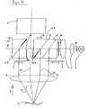
- FIG. 1 shows a preferred embodiment of the invention Microscope labeled 100 in total.
- the microscope 100 has a main objective 2 and a magnification system 9, in particular in the form of a zoom system.
- the axis of the overall optical system formed from the main objective 2 and the magnification system 9 is designated by 11.
- the observation channels of the microscope 100 run parallel to this axis 11.
- this axis 11 in the main objective 2 has a kink caused by the asymmetrical positioning of the magnification system 9 with respect to the main objective 2.
- This asymmetrical positioning of the main objective 2 and the magnification system 9 proves to be advantageous for certain applications.
- the prism block 8 has a total of 3 as mirrored surfaces trained deflection elements 16, 17, 18.
- the deflection element 16 is complete, the deflection element 17 at least partially designed as a physical beam splitter. That is, in the illustration of FIG. 1 of right on the deflecting elements 16, 17 bundle cross-section of the (shown schematically) light beam 12a from the light source 3 remains unchanged. The breakdown of the light beam 12a takes place uniformly over the entire Cross section of the deflection elements 16, 17. It can be seen that that along the illumination axis 12 of the deflection device 8 incident light bundles 12a on the deflection element 16 into a first partial beam 13, which reflects , and a second partial beam 12b, which is transmitted, is divided. Partial beam 13 provides a 6 ° illumination after passing through the main lens 2 available for object 1.
- the partial beam transmitted at the deflection element 16 12b is also in turn on the second deflection element 17 partially reflected and transmitted. That reflected Partial beam is at 14, the transmitted Partial beams denoted by 12c. That reflected Partial beam 14 initially runs essentially parallel to the partial beam 13. The partial beam 14 passes after passing through the main lens 2 + 2 ° lighting of object 1 available.
- the partial beam 15 represents a -2 ° illumination of the object 1 by means of further provided panels 6, 7 Partial beams 13, 14, 15 switched off or partially be dimmed. This can be used, for example, at Observation of an eye may cause disruptive corneal reflexes avoided, or the contrast of the red reflex be improved.
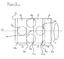
- figure 2 shows a projection of the deflection elements on the underside 8a of the deflection device 8.
- the respective lower edges 16a, 17a, 18a of the deflection elements 16, 17, 18, which actually run in this bottom 8a are with solid lines.
- the upper edges 16b, 17b, 18b of the deflection elements 16, 17, 18, which are in the top 8b, are shown with dashed lines.
- FIG. 2 shows the observation beam paths of the Microscope, two observation beam paths 22a, 22b for a main observer or operator and two observation beam paths 23a, 23b for a co-observer or Assistants are provided.
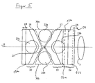
- the deflection elements 17, 18 partially fully mirrored, where regions of the deflection elements 17, 18 that are not fully mirrored either semi-translucent or partially mirrored or transparent can be trained. This fact will now explained with reference to Figure 3.
- the deflection elements 17, 18, as shown in Figure 3 are characterized by the fact that they are only partially are fully mirrored.
- the bottom and top edges of the deflecting elements 17, 18 are again 17a or 17b and 18a and 18b respectively.
- Between the edges 17a, 17b of the deflection element 17 can be seen in the one shown Projection arrow-shaped area 19, which has a lower edge 19a and an upper edge 19b.
- This area 19 is in turn the fully mirrored area of the deflecting element 17.
- the Area to the right of the upper edge 19b, here designated 17c, and the area to the left of the lower edge 19a, referred to here as area 17d, is transparent, so the corresponding overlap areas between the observation channels 23b and 22a, 22b and the fully mirrored area 19 are reduced. So is an essentially unimpeded observation through the observation channels 22a, 22b and 23b guaranteed.
- Deflection element 18 is designed in an analogous manner, wherein here the completely mirrored area again at 20 is designated. In comparison to the embodiment according to FIG 2 you can see that the overlap area between the full mirroring area 20 and the observation channel 23a is greatly reduced, so that overall a stereoscopic Observation for a co-observer using the beam paths 23a, 23b is provided. Also the areas of overlap between the fully mirrored area 19 and the observation beam paths 22a, 22b reduced compared to the embodiment according to FIG. 2.
- FIG. 4 Another preferred embodiment of the invention Lighting device will now be referenced to FIG Figures 4 and 5 shown.
- FIG. 4 corresponds to that shown there Microscope essentially that shown in FIG. so that the same components with the same reference number are designated.
- the microscope according to FIG. 4 differs differs from the microscope according to FIG. 1 in that the deflection device is not a one-piece prism block, but in the form of two prism blocks 48, 49, which are physical are separate from one another, is formed.
- glass blocks In place of the separated sections 30a, 30b it is possible to use glass blocks, which ensures can be that both the main surgeon and the Observers find the same observation conditions. It is also possible to complete such glass blocks omit and additionally optically imaging lenses in the observation beam path of co-observers or Main surgeon to compensate for any that may arise Focus difference between the observation beam path of the main surgeon or the co-observer.
- the +/- 2 ° lighting serves to Optimal observation of the red reflex. Switching the lighting from a + 2 ° lighting to a -2 ° lighting should serve in particular the red reflex then improve when the patient's eye, for example rolled away from the surgeon during phacoemulsification becomes. With conventional microscopes it was necessary to use one +/- 2 ° mirror active in the corresponding position by pressing a rotary knob. According to the invention is a simultaneous + 2 and -2 ° lighting in simple Can be provided in such a way that the surgeon has no such activities distracting from the actual operation must be expected.
- the + 2 ° lighting is usually used to observe the red reflex with the patient's eye centered.
- the - 2 ° lighting is particularly advantageous when the patient's eye is off-center used.
- the lighting device according to the invention stands out through a very easy handling in the practical Application off. Because of the summary of the deflection elements to a single prism block or to two prism blocks can do adjustment work to create optimal clearances between the deflection elements 16, 17, 18 completely or largely avoided. In the embodiment 1 and 4, it is possible to use the prism block 8 or the two prism blocks 48, 49 along the axis 12 move against each other, like this with the double arrows 25, 58, 59 is clearly shown.
- the prism block according to FIG. 1 can be produced in particular by using two essentially identical prism blocks which are rotated rotationally symmetrically with respect to one another, a parallelogram block being inserted between the rotationally symmetrically offset prisms. It should be noted that in the illustrated embodiments of the microscope, the observation channels are arranged essentially symmetrically about the observation axis 11. This observation axis does not necessarily correspond to the central axis or optical axis of the main objective 2.
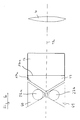
- FIG. 6 shows a further embodiment of the deflection device according to the invention in one direction accordingly the direction of the arrows P from FIG. 1 or FIG 4 shown.
- the one shown in Figure 6 as a prism block trained deflection device is with two deflection elements 16, 17 formed, wherein deflecting element 16 as physical beam splitter, and deflecting element 17 essentially is fully mirrored.
- Corresponding the representation according to FIGS. 1-5 shows the lower edges 16a and 17a of the deflection elements 16, 17. On one The corresponding upper edges are not shown here.
- the respective deflection elements or deflection surfaces 16a, 17a extend obliquely to the right into the plane of the drawing.
- Deflection element 16 serves analogously to that already described Embodiments of the lighting device according to the invention to provide 6 ° lighting, and deflection element 17 to provide a + 2 ° illumination.
- 6 to the left of the observation beam paths run the deflection element 17 22a, 22b of the stereomicroscope.
- Such a deflection device also builds shorter in the direction of the axis 12 shown than conventional deflection devices, especially since the to the two observation beam paths 22a, 22b Part of the deflection device to achieve an optimal and vignetting-free observation tapered is.
- the glass blocks with the glued as a prism block deflector It is also possible to separate the glass blocks from the Deflection device to be provided so that it only when needed can be used.
- FIG. 6 a representation of a Light source is dispensed with. It is also related with one provided between the light source and the deflection device optical system only schematically a lens, which is also denoted here by 4.
Abstract
Description
Die vorliegende Erfindung betrifft eine Beleuchtungseinrichtung für ein Mikroskop, insbesondere ein Operationsmikroskop, nach dem Oberbegriff des Patentanspruchs 1.The present invention relates to a lighting device for a microscope, in particular a surgical microscope, according to the preamble of claim 1.
Beleuchtungseinrichtungen für Operationsmikroskope verwenden in der Regel einen Beleuchtungsstrahlengang, der bezüglich des Beobachtungsstrahlengangs einen Winkel im Bereich von etwa 6° aufweist (sogenannte 6°-Beleuchtung). Hierdurch vermeidet man eine unerwünschte Schattenbildung, welche bei größeren Winkeln zwischen Beobachtungsstrahlengang und Beleuchtungsstrahlengang auftreten würde.Use lighting equipment for surgical microscopes usually an illumination beam path that is related to an angle in the range of the observation beam path of about 6 ° (so-called 6 ° lighting). hereby one avoids an undesirable shadow formation, which at larger angles between the observation beam path and the illumination beam path would occur.
Augenchirurgische Operationen stellen weitere besondere Anforderungen an die Beleuchtung eines Mikroskops. Zunächst erhält man eine ausreichende Plastizität des Bildes bei einem Beleuchtungswinkel von wiederum etwa 6°. Es ist jedoch für bestimmte augenchirurgische Beobachtungen oder Eingriffe notwenig, den so genannten Rotreflex zu erzeugen. Hierbei leuchtet die Pupille des operierten Auges durch von der Netzhaut zurückgestreutes Licht rötlich auf. Diese Beleuchtungsart ist beispielsweise bei Katarakt-Operationen von großer Bedeutung, da hierbei Gewebereste im Gegenlicht des Rotreflexes besonders gut zu erkennen sind. Die Rotreflexerzeugung benötigt kleinere Winkel zwischen dem Beobachtungsstrahlengang und dem Beleuchtungsstrahlengang, wobei hier Winkel im Bereich von 0°- 2° bevorzugt werden (sogenannte 2°-Beleuchtung).Ophthalmic surgery has other special requirements to the illumination of a microscope. First you get a sufficient plasticity of the picture with one Illumination angle of again about 6 °. However, it is for certain eye surgery observations or interventions necessary to create the so-called red reflex. in this connection the pupil of the operated eye shines through from the Scattered light retina reddish. This type of lighting is for example in cataract surgeries from of great importance, since here tissue remains against the light of the Red reflexes are particularly easy to see. The red reflex generation requires smaller angles between the observation beam path and the illuminating beam path, wherein here angles in the range of 0 ° - 2 ° are preferred (so-called 2 ° illumination).
Operationsmikroskope, welche mit zwei Paaren von stereoskopischen Beobachtungsstrahlengängen für einen Hauptoperateur bzw. einen Mitbeobachter ausgebildet sind, weisen oftmals insofern einen Mangel auf, als der Rotreflex zwar für den Hauptoperateur sehr gut, für den Mitbeobachter aber nur unzulänglich zu beobachten ist. Dieser erhält in Abhängigkeit von seiner Positionierung, entweder rechts oder links vom Hauptoperateur nur in einem seiner beiden Beobachtungskanäle einen guten Rotreflex. Dies wirkt sich störend auf die stereoskopische Beobachtung aus.Surgical microscopes, which use two pairs of stereoscopic Observation beam paths for a main surgeon or a co-observer are often trained insofar as the red reflex for the Main surgeon very good, but inadequate for the co-observer can be observed. This gets dependent from its positioning, either to the right or to the left of Main surgeon only in one of his two observation channels a good red reflex. This affects the stereoscopic observation.
Aus der DE 040 28 605 ist eine Beleuchtungseinrichtung für ein Operationsmikroskop mit einem Beleuchtungssystem, das außerhalb der optischen Achse des Mikroskopobjektivs angeordnet ist, und das Operationsgebiet parallel zur Objektivachse durch das Mikroskopobjektiv hindurch beleuchtet, und einem Umlenkelement auf der objektabgewandten Seite des Mikroskopobjektivs, welches das Operationsgebiet mit einem Bruchteil des Beleuchtungslichtes entlang der Objektivachse beleuchtet, bekannt. Diese Beleuchtungseinrichtung zeichnet sich dadurch aus, dass das Beleuchtungssystem objektivseitig mit einem Reflexionselement ausgestattet ist, welches das Beleuchtungslicht parallel zur Objektivachse zum Mikroskopobjektiv hin reflektiert, und dass das Umlenkelement das Operationsgebiet unter einem Neigungswinkel gegenüber der Objektivachse beleuchtet, der kleiner ist als der Neigungswinkel, unter dem das Reflexionselement das Operationsgebiet beleuchtet. Der größere Neigungswinkel beträgt hier bevorzugt 6°, der kleinere ist von 0° bis 6° variierbar. Als nachteilig bei dieser Konstruktion wird empfunden, dass die von dem Umlenkelement reflektierte Strahlung Randstrahlung der Beleuchtungspupille des Beleuchtungssystems ist, so dass bei einer achsnahen Beleuchtung, beispielsweise unter einem Winkel von 2° zum Beobachtungsstrahlengang, eine relativ inhomogene und vignettierte Ausleuchtung des Leuchtfeldes zu beobachten ist.DE 040 28 605 describes a lighting device for an operating microscope with an illumination system that arranged outside the optical axis of the microscope objective and the area of operation parallel to the lens axis illuminated through the microscope objective, and a deflection element on the side of the microscope objective facing away from the object, which the operation area with a Fraction of the illuminating light along the lens axis illuminated, known. This lighting device draws is characterized in that the lighting system on the lens side is equipped with a reflection element, which the illuminating light parallel to the lens axis to the microscope lens reflected and that the deflecting element the operation area opposite at an angle of inclination illuminated the lens axis, which is smaller than the angle of inclination, under which the reflection element the area of operation illuminated. The larger angle of inclination is here preferably 6 °, the smaller one can be varied from 0 ° to 6 °. A disadvantage of this construction is that that the radiation reflected by the deflecting element is marginal radiation the lighting pupil of the lighting system is, so that with a near-axis lighting, for example at an angle of 2 ° to the observation beam path, a relatively inhomogeneous and vignetted illumination of the Illuminated field can be observed.
Weitere Beleuchtungseinrichtungen für Operationsmikroskope sind aus der DE 196 50 773 A1 und der EP 1 109 046 A1 bekannt. Auch diese Beleuchtungseinrichtungen verwenden für die achsnahe Beleuchtung Randstrahlen der Beleuchtungspupille der Beleuchtungseinrichtung, so dass es auch hier zu den genannten Nachteilen kommt.Additional lighting devices for surgical microscopes are known from DE 196 50 773 A1 and EP 1 109 046 A1. These lighting devices also use for the near-axis lighting edge rays of the lighting pupil of the lighting device so that it too the disadvantages mentioned.
Als weiterer Nachteil beim Stand der Technik wird angesehen, dass die dort beschriebenen Operationsmikroskope relativ hoch bauen, da die 2°-Beleuchtung und die 6°-Beleuchtung übereinander angeordnet sind.Another disadvantage of the prior art is considered that the surgical microscopes described there are relative build high, because the 2 ° lighting and the 6 ° lighting are arranged one above the other.
Die Erfindung strebt an, eine Beleuchtungseinrichtung für ein Mikroskop zur Verfügung zu stellen, welche gegenüber herkömmlichen Einrichtungen dieser Art eine homogenere und vignettierungsfreiere Ausleuchtung des Leuchtfeldes ermöglicht. Gleichzeitig wird angestrebt, eine möglichst klein bauende Beleuchtungseinrichtung zur Verfügung zu stellen, so dass die Bauhöhe eines Mikroskops nicht in unerwünschter Weise vergrößert wird.The invention aims to provide a lighting device for to provide a microscope which is opposite conventional devices of this type a more homogeneous and Vignetting-free illumination of the illuminated field enables. At the same time, one strives to be as small as possible to provide building lighting equipment, so the overall height of a microscope is not undesirable Way is enlarged.
Dieses Ziel wird erreicht durch eine Beleuchtungseinrichtung
mit den Merkmalen des Patentanspruchs 1 sowie ein Mikroskop
mit den Merkmalen des Patentanspruchs 8. This goal is achieved by a lighting device
with the features of claim 1 and a microscope
with the features of
Erfindungsgemäß ist eine besonders homogene und vignettierungsfreie Ausleuchtung des Leuchtfeldes des Mikroskops gewährleistet, da durch die Verwendung von Umlenkelementen (zur Umlenkung von Licht aus einem Beleuchtungssystem auf ein zu beobachtendes Objekt), welche als physikalische Strahlenteiler ausgebildet sind, im wesentlichen der volle Querschnitt der Beleuchtungspupille sämtliche Spiegelelemente bzw. Umlenkelemente durchsetzt bzw. trifft. Bei den Beleuchtungseinrichtungen gemäß dem Stand der Technik wurden lediglich kleine, vollständig reflektierende Segmente der Umlenkelemente zur Umlenkung der Randbereiche der Beleuchtungspupillen verwendet. Bei den Strahlenteilern gemäß dem Stand der Technik handelt es sich somit um geometrische Strahlenteiler. Mit der erfindungsgemäßen Umlenkeinrichtung ist es insbesondere möglich, die einzelnen Umlenkelemente entlang einer einzigen optischen Achse zu positionieren, wodurch die Bauhöhe eines Mikroskops vorteilhaft vermindert werden kann.According to the invention is a particularly homogeneous and vignetting-free Illumination of the illuminated field of the microscope ensures because through the use of deflection elements (to redirect light from a lighting system an object to be observed), which is called physical Beam splitters are formed, essentially the full Cross section of the illumination pupil of all mirror elements or deflecting elements. Both Lighting devices according to the prior art only small, fully reflective segments the deflection elements for deflecting the edge areas of the illumination pupils used. According to the beam splitters the prior art is therefore geometric Beam splitter. With the deflection device according to the invention it is in particular possible to use the individual deflection elements to position along a single optical axis whereby the overall height of a microscope is advantageously reduced can be.
Vorteilhafte Ausgestaltungen der erfindungsgemäßen Beleuchtungseinrichtung sowie des erfindungsgemäßen Mikroskops sind Gegenstand der Unteransprüche.Advantageous refinements of the lighting device according to the invention and the microscope according to the invention are the subject of the subclaims.
Gemäß einer bevorzugten Ausführungsform der erfindungsgemäßen Beleuchtungseinrichtung weist die Umlenkeinrichtung wenigstens drei Umlenkelemente auf. Die besonders bevorzugte Ausgestaltung mit drei Umlenkelementen ermöglicht beispielsweise bei Operationsmikroskopen eine 6°-Beleuchtung, +2°-Beleuchtung und -2°-Beleuchtung.According to a preferred embodiment of the invention The deflection device has at least one lighting device three deflection elements. The most preferred Design with three deflection elements enables, for example 6 ° illumination for surgical microscopes, + 2 ° lighting and -2 ° lighting.
Gemäß einer besonders bevorzugten Ausführungsform der Erfindung, für die gesondert um Schutz nachgesucht wird, sind zwei Umlenkelemente derart angeordnet, dass eine gleichzeitige +2°- und -2°-Beleuchtung möglich ist. Diese Beleuchtungsmöglichkeit erweist sich insbesondere bei den Rotreflex einsetzenden operativen Techniken als vorteilhaft, bei denen es zu einer Verrollung des Auges kommen kann. Als Beispiel sei hier die Phakoemulsifikation genannt. Bei gleichzeitiger +2°- und -2°-Beleuchtung ist gewährleistet, dass der Operateur während der Arbeit keine Einstellungen am Mikroskop verändern muss. Es ist auch eine gleichzeitige +2°-, -2°- und 6°-Beleuchtung möglich, sowie auch beliebige andere Kombinationen, welche beispielsweise durch Verwendung von entsprechend positionierbaren Blenden eingestellt werden können.According to a particularly preferred embodiment of the invention, for whom protection is sought separately two deflection elements arranged such that a simultaneous + 2 ° and -2 ° lighting is possible. This lighting option is particularly evident in the red reflex operational techniques as advantageous, at which can cause the eye to roll. As An example is phacoemulsification. at simultaneous + 2 ° and -2 ° lighting is guaranteed, that the operator has no settings while working on the microscope. It is also a simultaneous one + 2 °, -2 ° and 6 ° lighting possible, as well as any other combinations, for example through use of correspondingly positioned panels can be.
Zweckmäßigerweise ist wenigstens eines der Umlenkelemente wenigstens teilweise vollverspiegelt ausgebildet. Mittels dieser Maßnahme kann Licht, welches auf die vollverspiegelten Bereiche auftrifft, vollständig auf das zu beobachtende Objekt gelenkt werden, wodurch die Beleuchtungsstärke vorteilhaft beeinflussbar ist. Ferner können auf diese Weise Überlappungen zwischen den Beobachtungsstrahlengängen des Mikroskops und den vollverspiegelten Bereichen in einfacher Weise konstruiert werden. Derartige Überlappungen sind für bestimmte Anwendungen im Rahmen der Augenchirurgie, beispielsweise zur Bereitstellung bzw. Einstellung des Rotreflexes notwendig.At least one of the deflection elements is expedient at least partially fully mirrored. through This measure can light that is on the fully mirrored Areas strikes completely on the observed Object can be directed, making the illuminance advantageous can be influenced. Furthermore, in this way Overlaps between the observation beam paths of the Microscope and the fully mirrored areas in easier Be constructed way. Such overlaps are for certain eye surgery applications, for example to provide or adjust the red reflex necessary.
Gemäß einer besonders bevorzugten Ausführungsform der erfindungsgemäßen Beleuchtung ist die Umlenkeinrichtung als teilreflektierende Flächen aufweisende Prismenkombination ausgebildet. Prismensysteme erweisen sich in der Praxis als mit relativ geringem Aufwand justierbar. Es ist jedoch ebenfalls denkbar, die Umlenkeinrichtung mit entsprechend positionierten, teilreflektierenden Spiegeln auszubilden. According to a particularly preferred embodiment of the invention Lighting is the deflection device as prism combination with partially reflecting surfaces educated. In practice, prism systems prove to be adjustable with relatively little effort. However, it is also conceivable with the deflection device accordingly to position positioned, partially reflecting mirrors.
Gemäß einer besonders bevorzugten Ausführungsform der erfindungsgemäßen Beleuchtungseinrichtung ist die Umlenkeinrichtung als einheitlicher bzw. einstückiger Prismenblock ausgebildet. Bei einem derartigen einheitlichen Prismenblock ist die bei der Mikroskopmontage notwendige Justierarbeit auf ein Minimum begrenzbar. Ein derartiger Prismenblock erweist sich ferner im Mikroskopbetrieb als sehr robust.According to a particularly preferred embodiment of the invention The lighting device is the deflection device as a uniform or one-piece prism block educated. With such a uniform prism block is the adjustment work required for microscope assembly limited to a minimum. Such a prism block also proves to be very robust in microscope operation.
Es ist ebenfalls vorteilhaft möglich, dass die Umlenkeinrichtung zwei räumlich voneinander getrennte Prismenblöcke aufweist. Mit dieser Maßnahme sind beispielsweise die Beobachtungsstrahlengänge beeinträchtigende Klebefugen zwischen den jeweiligen Prismen der Umlenkeinrichtung, welche zu Doppelbildern oder Reflexen führen können, im wesentlichen vermeidbar. Es sei angemerkt, dass die Umlenkelemente auch als entsprechend reflektierende bzw. transmittierende Spiegel, welche unabhängig von Prismenblöcken positioniert sind, ausgebildet sein könnten.It is also advantageously possible for the deflection device two prism blocks separated from each other having. With this measure, the observation beam paths are, for example impairing adhesive joints between the respective prisms of the deflection device, which can lead to double images or reflections, essentially preventable. It should be noted that the deflection elements also as correspondingly reflecting or transmitting Mirror, which is positioned independently of prism blocks are, could be trained.
Gemäß einer bevorzugten Ausgestaltung des erfindungsgemäßen Mikroskops ist dieses als Stereomikroskop ausgebildet. Hierbei wird besonders bevorzugt, dass das Stereomikroskop zwei Beobachtungsstrahlengänge für einen Hauptoperateur und zwei weitere Beobachtungsstrahlengänge für einen Assistenten aufweist. Insbesondre bei einem derartigen Stereomikroskop mit Beobachtungsstrahlengängen für einen Hauptoperateur und einen Assistenten lassen sich im Vergleich zu herkömmlichen Mikroskopen dieser Art sowohl für den Hauptoperateur als auch den Assistenten Rotreflexeigenschaften in gewünschter Weise einstellen. Die Ausnutzung im wesentlichen der gesamten Beleuchtungspupille führt insgesamt dazu, dass Vignettierungen weitgehend vermieden werden können, und sowohl für den Hauptbeobachter als auch den Assistenten ein homogenes Leuchtfeld bereitgestellt werden kann.According to a preferred embodiment of the invention Microscope this is designed as a stereomicroscope. It is particularly preferred here that the stereomicroscope two observation beam paths for a main surgeon and two further observation beam paths for an assistant having. Especially with such a stereo microscope with observation beam paths for a main surgeon and an assistant can be compared to conventional Microscopes of this type for both the main surgeon as well as the wizard red reflex properties in set as desired. The exploitation essentially of the entire illumination pupil leads to that vignetting can be largely avoided, and for both the primary observer and the assistant a homogeneous light field can be provided.
Zweckmäßigerweise weist das erfindungsgemäße Mikroskop Blenden auf, mit denen die Beleuchtungsstrahlengänge wahlweise eingeschaltet oder abgeschaltet werden können. Hierdurch ist es beispielsweise möglich, eine 0°-Beleuchtung im wesentlichen abzustellen, so dass die Entstehung des Rotreflexes bei Bedarf auch vermieden werden kann.The microscope according to the invention expediently has Apertures with which the illuminating beam paths are optional can be switched on or off. hereby it is possible, for example, a 0 ° lighting in the essentially turn off so that the emergence of the red reflex can also be avoided if necessary.
Ferner ist es gemäß einer besonders bevorzugten Ausgestaltung des erfindungsgemäßen Mikroskops vorgesehen, dass die Umlenkeinrichtung bezüglich der optischen Achse des Mikroskop-Hauptobjektivs querverschiebbar ist. Hierbei ist insbesondere eine Querverschiebbarkeit senkrecht zur optischen Achse des Hauptobjektivs vorgesehen. Hierdurch ergeben sich weitere Variationsmöglichkeiten zur Einstellung von Beleuchtungswinkeln und/oder Überlappungen zwischen vollverspiegelten Bereichen der Umlenkelemente und Beobachtungsstrahlengängen, wodurch die Rotreflexausbildung beeinflussbar ist.Furthermore, it is according to a particularly preferred embodiment of the microscope according to the invention provided that the Deflection device with respect to the optical axis of the main microscope objective is displaceable. Here is particular a transverse displacement perpendicular to the optical Axis of the main lens is provided. This results in further variation options for setting lighting angles and / or overlaps between fully mirrored ones Areas of the deflection elements and observation beam paths, whereby the red reflex formation can be influenced is.
Gemäß einer weiteren bevorzugten Ausführungsform des erfindungsgemäßen Mikroskops, für die gesondert um Schutz nachgesucht wird, weist das Mikroskop eine Umlenkeinrichtung mit einem als physikalischer Strahlenteiler ausgebildeten Umlenkelement, und einem weiteren reflektierend ausgebildeten Umlenkelement auf, wobei ferner Glasblöcke vorgesehen sind, die derart positioniert sind, dass die Beobachtungsstrahlengänge des Mikroskops durch sie hindurchlaufen. Mit dieser Maßnahme ist es möglich, die Pupillen der Beobachtungsstrahlengänge in wirksamer Weise einzuschnüren, wodurch insgesamt die Bauhöhe des Mikroskops reduziert werden kann. Durch entsprechende Ausbildung der Umlenkeinrichtung ist es ferner möglich, die Umlenkeinrichtung in Richtung der optischen Achse kürzer bauend auszugestalten.According to a further preferred embodiment of the invention Microscope for which protection is requested separately the microscope has a deflection device with a trained as a physical beam splitter Deflection element, and another reflective Deflection element, wherein glass blocks are also provided are positioned such that the observation beam paths through the microscope. With This measure makes it possible to use the pupils of the observation beam paths constrict effectively, thereby the overall height of the microscope can be reduced can. By appropriate design of the deflection device it is also possible to move the deflection device in the direction to make the optical axis shorter.
Die Erfindung wird nun anhand der beigefügten Zeichnungen
weiter beschrieben. In dieser zeigt
In Figur 1 ist eine bevorzugte Ausführungsform des erfindungsgemäßen Mikroskops insgesamt mit 100 bezeichnet.1 shows a preferred embodiment of the invention Microscope labeled 100 in total.
Das Mikroskop 100 weist ein Hauptobjektiv 2 und ein
insbesondere als Zoom-System ausgebildetes
Vergrößerungssystem 9 auf. Die Achse des aus Hauptobjektiv
2 und Vergrößerungssystem 9 gebildeten optischen
Gesamtsystems ist mit 11 bezeichnet. Die Beobachtungskanäle
des Mikroskops 100 verlaufen parallel zu dieser Achse 11.
Wie man aus Figur 1 erkennt, weist diese Achse 11 im
Hauptobjektiv 2 einen durch die asymmetrische
Positionierung des Vergrößerungssystems 9 bezüglich des
Hauptobjektivs 2 verursachten Knick auf. Diese
asymmetrische Positionierung von Hauptobjektiv 2 und
Vergrößerungssystem 9 erweist sich für bestimmte Anwendungen
als vorteilhaft. So würde es bei ausreichend großer Beleuchtungspupille
der weiter unten erläuterten 6°-Beleuchtung
(Teilstrahlenbündel 13) bei mittiger bzw. symmetrischer
Anordnung des Hauptobjektivs 2 bezüglich des
Vergrößerungssystems 9 zu einem Abschneiden von Randstrahlung
kommen, da in diesem Fall die in der Figur 1 rechte
Seite des Hauptobjektivs in die Beleuchtungspupille des
Teilstrahlenbündels 13 fallen würde.
Licht zur Beleuchtung eines zu beobachtenden Objektes 1 gelangt
von einer Lichtquelle 3 über eine als Prismenblock 8
ausgebildete Umlenkeinrichtung auf das Objekt 1. Zwischen
der Lichtquelle 3 und der Umlenkeinrichtung 8 sind beispielhaft
zwei Linsen 4, 5 sowie zwei Blenden 28, 29 vorgesehen.
Als Lichtquelle 3 sind alle üblichen Lichtquellen,
insbesondere kohärente und/oder inkohärente Lichtquellen,
wie beispielsweise Glühbirnen, Faserbeleuchtungen, Entladungslampen,
Laser usw. einsetzbar.The microscope 100 has a main objective 2 and a
Light for illuminating an object 1 to be observed reaches the object 1 from a
Der Prismenblock 8 weist insgesamt 3 als verspiegelte Flächen
ausgebildete Umlenkelemente 16, 17, 18 auf.The
Das Umlenkelement 16 ist vollständig, das Umlenkelement 17
wenigstens teilweise als physikalischer Strahlenteiler ausgebildet.
Das heißt, der in der Darstellung der Figur 1 von
rechts auf die Umlenkelemente 16, 17 auftreffende Bündelquerschnitt
des (schematisch dargestellten) Lichtbündels
12a aus der Lichtquelle 3 bleibt unverändert. Die Aufteilung
des Lichtbündels 12a erfolgt gleichmäßig über den gesamten
Querschnitt der Umlenkelemente 16, 17. Man erkennt,
dass das entlang der Beleuchtungsachse 12 der Umlenkeinrichtung
8 einfallende Lichtbündel 12a am Umlenkelement 16
in ein erstes Teilstrahlenbündel 13, welches reflektiert
wird, und ein zweites Teilstrahlenbündel 12b, welches
transmittiert wird, aufgeteilt wird. Teilstrahlenbündel 13
stellt nach Durchgang durch das Hauptobjektiv 2 eine 6°-Beleuchtung
für das Objekt 1 zur Verfügung.The
Das an dem Umlenkelement 16 transmittierte Teilstrahlenbündel
12b wird an dem zweiten Umlenkelement 17 ebenfalls wiederum
teilweise reflektiert und transmittiert. Das reflektierte
Teilstrahlenbündel ist mit 14, das transmittierte
Teilstrahlenbündel mit 12c bezeichnet. Das reflektierte
Teilstrahlenbündel 14 verläuft zunächst im wesentlichen parallel
zu dem Teilstrahlenbündel 13. Das Teilstrahlenbündel
14 stellt nach Durchgang durch das Hauptobjektiv 2 eine
+2°-Beleuchtung des Objekts 1 zur Verfügung. The partial beam transmitted at the
Das an dem Umlenkelement 17 transmittierte Teilstrahlenbündel
12c trifft anschließend auf das dritte Umlenkelement
18, welches zweckmäßigerweise vollverspiegelt ausgebildet
ist. Das an dem Umlenkelement 18 reflektierte, mit 15 bezeichnetet
Teilstrahlenbündel trifft, nach Durchgang durch
das Hauptobjektiv 2, ebenfalls auf das Objekt 1. Das Teilstrahlenbündel
15 stellt eine -2°-Beleuchtung des Objekts 1
dar. Mittels weiterhin vorgesehener Blenden 6, 7 können die
Teilstrahlenbündel 13, 14, 15 ausgeschaltet oder teilweise
abgeblendet werden. Hiermit können beispielsweise bei der
Beobachtung eines Auges unter Umständen störende Kornearreflexe
vermieden, oder auch der Kontrast des Rotreflexes
verbessert werden.The partial beam transmitted at the
Die Anordnung der bereits erwähnten Beobachtungsstrahlengänge
des Mikroskops bezüglich der Umlenkelemente bzw. Reflexionsflächen
16, 17, 18 wird aus Figur 2 deutlich. Figur
2 stellt eine Projektion der Umlenkelemente auf die Unterseite
8a der Umlenkeinrichtung 8 dar. Die jeweiligen Unterkanten
16a, 17a, 18a der Umlenkelemente 16, 17, 18, welche
tatsächlich in dieser Unterseite 8a verlaufen, sind mit
durchgezogenen Linien dargestellt. Die Oberkanten 16b, 17b,
18b der Umlenkelemente 16, 17, 18, welche in der Oberseite
8b verlaufen, sind mit gestrichelten Linien dargestellt.The arrangement of the observation beam paths already mentioned
of the microscope with respect to the deflection elements or reflection surfaces
16, 17, 18 is clear from Figure 2. figure
2 shows a projection of the deflection elements on the underside
8a of the
In Figur 2 erkennt man die Beobachtungsstrahlengänge des
Mikroskops, wobei zwei Beobachtungsstrahlengänge 22a, 22b
für ein Hauptbeobachter bzw. -operateur und zwei Beobachtungsstrahlengänge
23a, 23b für einen Mitbeobachter bzw.
Assistenten vorgesehen sind.FIG. 2 shows the observation beam paths of the
Microscope, two
Man erkennt, dass die Mitbeobachterstrahlengänge 23a, 23b
vollständig, und die Hauptbeobachterstrahlengänge 22a, 22b
teilweise von den Projektionen der Umlenkelemente bzw.
Spiegelflächen 16, 17, 18 überlagert werden. Die vollständig
oder teilweise verspiegelten Bereiche der Umlenkelemente
16, 17, 18 sind in Figur 2 mit geschweiften Klammern
veranschaulicht und mit 24, 19, bzw. 20 bezeichnet. Es sei
noch einmal darauf hingewiesen, dass in Ausführungsbeispiel
gemäß Figur 2 die verspiegelten Bereiche im wesentlichen
die gesamte Fläche der Umlenkelemente 16, 17, 18 überdecken.
Bei beispielsweise vollständiger Verspiegelung der
Umlenkelemente 17, 18 sind daher die
Beobachtungsstrahlengänge 23a, 23b blockiert, so dass ein
derart ausgebildetes Mikroskop lediglich für die
stereoskopische Beobachtung durch einen Hauptbeobachter
geeignet ist. (Benutzung der Beobachtungskanäle 22a, 22b).It can be seen that the
Bei teilverspiegelter Ausbildung der Umlenkelemente 17, 18
ist hingegen eine Beobachtung des Objekts 1 auch durch die
Beobachtungskanäle 23a, 23b möglich.When the deflecting
Zur Optimierung der Lichtausbeute in den dargestellten
Beobachtungsstrahlengängen wird bevorzugt, die Umlenkelemente
17, 18 teilweise vollverspiegelt auszubilden, wobei
nicht vollverspiegelte Bereiche der Umlenkelemente 17, 18
entweder halbdurchlässig bzw. teilverspiegelt oder transparent
ausgebildet sein können. Dieser Sachverhalt wird nun
unter Bezugnahme auf Figur 3 näher erläutert.To optimize the light output in the shown
Observation beam paths are preferred, the
Die Umlenkelemente 17, 18, wie sie in Figur 3 dargestellt
sind, zeichnen sich dadurch aus, dass sie nur teilweise
vollverspiegelt ausgebildet sind. Die Unterkanten und Oberkanten
der Umlenkelemente 17, 18 sind wiederum mit 17a bzw.
17b und 18a bzw. 18b bezeichnet. Zwischen den Kanten 17a,
17b des Umlenkelements 17 erkennt man einen in der dargestellten
Projektion pfeilförmig ausgebildeten Bereich 19,
welcher eine untere Kante 19a und eine obere Kante 19b aufweist.
Bei diesem Bereich 19 handelt es sich wiederum um
den vollverspiegelten Bereich des Umlenkelements 17. Der
Bereich rechts neben der Oberkante 19b, hier als 17c bezeichnet,
sowie der Bereich links neben der Unterkante 19a,
hier als Bereich 17d bezeichnet, ist transparent ausgebildet,
so dass die entsprechenden Überlappungsbereiche zwischen
den Beobachtungskanälen 23b bzw. 22a, 22b und dem
vollverspiegelten Bereich 19 verkleinert sind. Somit ist
eine im wesentlichen ungehinderte Beobachtung durch die Beobachtungskanäle
22a, 22b und 23b gewährleistet.The
Umlenkelement 18 ist in analoger Weise ausgebildet, wobei
hier der vollständig verspiegelte Bereich wiederum mit 20
bezeichnet ist. Im Vergleich zur Ausführungsform gemäß Figur
2 erkennt man, dass der Überlappungsbereich zwischen
dem Vollverspiegelungsbereich 20 und dem Beobachtungskanal
23a stark vermindert ist, so dass insgesamt eine stereoskopische
Beobachtung für einen Mitbeobachter unter Verwendung
der Strahlengänge 23a, 23b zur Verfügung gestellt ist. Auch
die Überlappungsbereiche zwischen dem vollverspiegelten Bereich
19 und den Beobachtungsstrahlengängen 22a, 22b sind
gegenüber der Ausführung gemäß Figur 2 vermindert.
Die vollverspiegelten Bereiche 19, 20 gemäß Figur 3, sind
in Figur 1 schematisch als fettgedruckte Linien auf den Umlenkelementen
17, 18 eingezeichnet.The fully mirrored
Es sei angemerkt, dass eine Überlappung der verspiegelten
Bereiche 19, 20 mit den Beobachtungsstrahlengängen 22a,
22b, 23a, 23b zur Erzeugung des bei bestimmten Anwendungen
gewünschten Rotreflexes in gewissem Umfang notwendig ist. It should be noted that an overlap of the mirrored
Durch entsprechende Dimensionierung bzw. Ausbildung der
vollverspiegelten Bereiche 19, 20 auf den Umlenkelementen
17, 18 ist dieser Rotreflex, beispielsweise bezüglich Intensität
und Kontrast, optimierbar.By appropriate dimensioning or training of
fully mirrored
Eine weitere bevorzugte Ausführungsform der erfindungsgemäßen Beleuchtungseinrichtung wird nun unter Bezugnahme auf die Figuren 4 und 5 dargestellt.Another preferred embodiment of the invention Lighting device will now be referenced to FIG Figures 4 and 5 shown.
Wie aus Figur 4 zu erkennen ist, entspricht das dort dargestellte Mikroskop im wesentlichen dem in Figur 1 dargestellten, so dass gleiche Bauteile mit gleichem Bezugszeichen bezeichnet sind. Das Mikroskop gemäß Figur 4 unterscheidet sich von dem Mikroskop gemäß Figur 1 dadurch, dass die Umlenkeinrichtung nicht als einteiliger Prismenblock, sondern in Form von zwei Prismenblöcken 48, 49, welche physisch getrennt voneinander sind, ausgebildet ist.As can be seen from FIG. 4, this corresponds to that shown there Microscope essentially that shown in FIG. so that the same components with the same reference number are designated. The microscope according to FIG. 4 differs differs from the microscope according to FIG. 1 in that the deflection device is not a one-piece prism block, but in the form of two prism blocks 48, 49, which are physical are separate from one another, is formed.
In Figur 5 erkennt man anschaulich, dass durch Entfernen
von zwei keilartigen Abschnitten 30a, 30b aus einem einstückigen
Prismenblock, wie er beispielsweise in Figur 3 dargestellt
ist, die zwei Prismenblöcke aufweisende Umlenkeinrichtung
gemäß der Ausführungsform der Figuren 4 und 5 bereitstellbar
ist. Die Entfernung derartiger Abschnitte 30a,
30b erweist sich insofern als vorteilhaft, als Kittflächen,
wie sie typischerweise an den die Umlenkelemente darstellenden
Grenzflächen zwischen den einzelnen Prismen der
Prismenblöcke entstehen, wirksam vermieden werden können.
Dies ist günstig, da Kittflächen zwischen zwei Prismen in
der Praxis nicht ideal planparallel ausgestaltet werden
können, wobei ferner der verwendete Kitt einen etwas anderen
Brechungsindex als die aneinander zu verklebenden Prismen
aufweist. Insgesamt kommt es herkömmlicherweise durch
Spiegelungseffekte bzw. Brechungseffekte an den Trennlinien,
wodurch Doppelbilder entstehen können. Derartige Doppelbilder
können gemäß der Ausführungsform des erfindungsgemäßen
Mikroskops, wie sie in Figur 4, 5 dargestellt ist,
sowohl für den Hauptoperateur als auch für den Mitbeobachter,
weitgehend vermieden werden. Es sei angemerkt, dass
eine zwei Prismenblöcke aufweisende Prismenkombination
nicht notwendigerweise durch die dargestellte Bearbeitung
bzw. Trennung eines einheitlichen Prismenblocks bereitgestellt
werden muss. Es ist gleichfalls möglich, die zwei
Prismenblöcke getrennt voneinander herzustellen.In Figure 5 one can clearly see that by removing
of two wedge-
An die Stelle der herausgetrennten Abschnitte 30a, 30b ist
es möglich, Glasblöcke einzusetzen, wodurch gewährleistet
werden kann, dass sowohl der Hauptoperateur als auch der
Mitbeobachter die gleichen Beobachtungsbedingungen vorfinden.
Es ist ebenfalls möglich, derartige Glasblöcke vollständig
wegzulassen und zusätzlich optisch abbildende Linsen
in den Beobachtungsstrahlengang von Mitbeobachter oder
Hauptoperateur zum Ausgleich einer gegebenenfalls auftretenden
Fokusdifferenz zwischen dem Beobachtungsstrahlengang
des Hauptoperateurs bzw. des Mitbeobachters vorzusehen.In place of the separated
Wie bereits erwähnt, dient die +/-2°-Beleuchtung dazu, den Rotreflex optimal zu beobachten. Eine Umschaltung der Beleuchtung von einer +2°-Beleuchtung auf eine -2°-Beleuchtung soll insbesondere dazu dienen, den Rotreflex dann zu verbessern, wenn das Patientenauge beispielsweise bei der Phako-Emulsifikation vom Operateur weg verrollt wird. Bei herkömmlichen Mikroskopen war es notwendig, einen +/-2°-Spiegel aktiv in die entsprechende Position durch Betätigung eines Drehknopfes einzustellen. Erfindungsgemäß ist eine gleichzeitige +2- und -2°-Beleuchtung in einfacher Weise bereitstellbar, so dass dem Operateur keine derartigen, von der eigentlichen Operation ablenkenden Tätigkeiten zugemutet werden müssen.As already mentioned, the +/- 2 ° lighting serves to Optimal observation of the red reflex. Switching the lighting from a + 2 ° lighting to a -2 ° lighting should serve in particular the red reflex then improve when the patient's eye, for example rolled away from the surgeon during phacoemulsification becomes. With conventional microscopes it was necessary to use one +/- 2 ° mirror active in the corresponding position by pressing a rotary knob. According to the invention is a simultaneous + 2 and -2 ° lighting in simple Can be provided in such a way that the surgeon has no such activities distracting from the actual operation must be expected.
Durch die in einfacher Weise variierbare Überlappung der Vollverspiegelungsbereiche auf den Umlenkelementen mit den Beobachtungsstrahlenkanälen sind sowohl für den Hauptoperateur als auch den Assistent jeweils in beiden Beobachtungsstrahlenkanälen optimale Rotreflexe erzielbar. Die +2°-Beleuchtung dient in der Regel zur Beobachtung des Rotreflexes bei zentriertem Patientenauge. Die - 2°-Beleuchtung ist insbesondere bei dezentriertem Patientenauge vorteilhaft einsetzbar.Due to the easily variable overlap of the Full mirroring areas on the deflection elements with the Observation beam channels are both for the main surgeon as well as the assistant in each of the two observation beam channels optimal red reflections can be achieved. The + 2 ° lighting is usually used to observe the red reflex with the patient's eye centered. The - 2 ° lighting is particularly advantageous when the patient's eye is off-center used.
Die erfindungsgemäße Beleuchtungseinrichtung zeichnet sich
durch eine sehr einfache Handhabbarkeit bei der praktischen
Anwendung aus. Aufgrund der Zusammenfassung der Umlenkelemente
zu einem einzigen Prismenblock oder zu zwei Prismenblöcken
können Justierarbeiten zur Schaffung optimaler Abstände
zwischen den Umlenkelementen 16, 17, 18 vollständig
bzw. weitgehend vermieden werden. Bei der Ausführungsform
gemäß Figuren 1 und 4 ist es möglich, den Prismenblock 8
bzw. die beiden Prismenblöcke 48, 49 entlang der Achse 12
gegeneinander zu verschieben, wie dies mittels der Doppelpfeile
25, 58, 59 anschaulich dargestellt ist.The lighting device according to the invention stands out
through a very easy handling in the practical
Application off. Because of the summary of the deflection elements
to a single prism block or to two prism blocks
can do adjustment work to create optimal clearances
between the
Es ist ferner möglich, die Umlenkelemente 16, 17, 18 teilweise
geschwärzt auszubilden. Mit dieser Maßnahme können
unerwünschte Reflexe wirksam unterdrückt werden. Es ist ebenfalls
möglich, beispielsweise an der Unterseite und, unter
Bezugnahme auf Figur 4, auf der Innenseite der Umlenkeinrichtung
8 bzw. 48, 49 absorbierende Elemente, insbesondere
Bleche vorzusehen, mit denen ebenfalls unerwünschte
Reflexe aufgrund von Mehrfachspiegelungen vermieden werden
können. Ein derartiges Blech ist in Figur 1 schematisch
dargestellt und mit 17e bezeichnet. In Figur 4 ist mittels
strichpunktierter Linien eine derartige absorbierende Oberflächenbelegung,
welche beispielsweise als Lichtfalle oder
optischer Filter, beispielsweise geschwärzt oder selektiv
absorbierend, ausgebildet ist, mit 17f bezeichnet.It is also possible to partially divert the
Mit der Schwärzung der Flächen können insbesondere auch interne
Reflexe vermieden werden. Mittels der vorgesehenen
Elemente, beispielsweise dem Blech 17e oder den Oberflächenbelegungen
17f, können unerwünschte Reflexe am Hauptobjektiv
vermieden werden.With the blackening of the surfaces, internal ones can also be used
Reflexes are avoided. By means of the provided
Elements, for example the
Der Prismenblock gemäß Figur 1 ist insbesondere durch
Verwendung zweier im wesentlichen identischer
Prismenblöcke, welche rotationssymmetrisch zueinander
verdreht werden, herstellbar, wobei zwischen die
rotationssymmetrisch versetzten Prismen ein Parallelogramm-Block
einzusetzen ist.
Es sei angemerkt, dass in den dargestellten Ausführungsformen
des Mikroskops die Beobachtungskanäle im wesentlichen
symmetrisch um die Beobachtungsachse 11 angeordnet sind.
Diese Beobachtungsachse entspricht nicht notwendigerweise
der Mittelachse bzw. optischen Achse des Hauptobjektivs 2.The prism block according to FIG. 1 can be produced in particular by using two essentially identical prism blocks which are rotated rotationally symmetrically with respect to one another, a parallelogram block being inserted between the rotationally symmetrically offset prisms.
It should be noted that in the illustrated embodiments of the microscope, the observation channels are arranged essentially symmetrically about the
In Figur 6 ist schließlich eine weitere Ausführungsform der
erfindungsgemäßen Umlenkeinrichtung in einer Richtung entsprechend
der Richtung der Pfeile P aus Figur 1 oder Figur
4 dargestellt. Die in Figur 6 dargestellte, als Prismenblock
ausgebildete Umlenkeinrichtung ist mit zwei Umlenkelementen
16, 17 ausgebildet, wobei Umlenkelement 16 als
physikalischer Strahlenteiler, und Umlenkelement 17 im wesentlichen
vollverspiegelt ausgebildet ist. Entsprechend
der Darstellung gemäß Figuren 1 - 5 erkennt man die Unterkanten
16a bzw. 17a der Umlenkelemente 16, 17. Auf eine
Darstellung der entsprechenden Oberkanten ist hier verzichtet.
Der Anschaulichkeit halber sei darauf hingewiesen,
dass die jeweiligen Umlenkelemente bzw. Umlenkflächen 16a,
17a, in die Zeichenebene hinein schräg nach rechts erstrecken.
Umlenkelement 16 dient analog zu den bereits beschriebenen
Ausführungsformen der erfindungsgemäßen Beleuchtungseinrichtung
zur Bereitstellung einer 6°-Beleuchtung,
und Umlenkelement 17 zur Bereitstellung einer
+2°-Beleuchtung. In der Darstellung der Figur 6 links neben
dem Umlenkelement 17 verlaufen die Beobachtungsstrahlengänge
22a, 22b des Stereomikroskops. Gemäß dieser Ausführungsform
sind in die Beobachtungsstrahlengänge 22a, 22b Glasblöcke
60, 61 eingebracht, welche für die Beobachtungsstrahlengänge
transparent sind. Mittels der Einbringung
derartiger Glasblöcke ist eine Einschnürung der Pupillen
der Beobachtungsstrahlengänge erzielbar, wodurch insgesamt
die Bauhöhe der Beleuchtungseinrichtung bzw. des Mikroskops
reduziert werden kann. Ferner baut eine derartige Umlenkeinrichtung
in Richtung der dargestellten Achse 12 kürzer
als herkömmliche Umlenkeinrichtungen, insbesondere da der
zu den beiden Beobachtungsstrahlengängen 22a, 22b hingerichtete
Teil der Umlenkeinrichtung zur Erzielung einer optimalen
und vignettierungsfreien Beobachtung verjüngt ausgebildet
ist. Zweckmäßigerweise sind die Glasblöcke mit der
als Prismenblock ausgebildeten Umlenkeinrichtung verklebt.
Es ist ebenfalls möglich, die Glasblöcke getrennt von der
Umlenkeinrichtung vorzusehen, so dass sie nur bei Bedarf
einsetzbar sind. Finally, FIG. 6 shows a further embodiment of the
deflection device according to the invention in one direction accordingly
the direction of the arrows P from FIG. 1 or FIG
4 shown. The one shown in Figure 6 as a prism block
trained deflection device is with two
Es sei angemerkt, dass in Figur 6 auf einer Darstellung einer Lichtquelle verzichtet ist. Ferner ist im Zusammenhang mit einem zwischen Lichtquelle und Umlenkeinrichtung vorgesehenen optischen System lediglich schematisch eine Linse, welche auch hier mit 4 bezeichnet ist, dargestellt. It should be noted that in FIG. 6 a representation of a Light source is dispensed with. It is also related with one provided between the light source and the deflection device optical system only schematically a lens, which is also denoted here by 4.
- 11
- Objektobject
- 22
- Hauptobjektivmain objective
- 33
- Lichtquellelight source
- 4, 54, 5
- Linsenlenses
- 6, 76, 7
- Blendendazzle
- 88th
- Umlenkeinrichtung (Prismenblock)Deflection device (prism block)
- 8a8a
- Unterseite der UmlenkeinrichtungBottom of the deflection device
- 8b8b
- Oberseite der UmlenkeinrichtungTop of the deflection device
- 99
- Vergrößerungssystemmagnification system
- 1111
- optische Achseoptical axis
- 1212
- Achse der UmlenkeinrichtungAxis of the deflection device
- 12a, b, c12a, b, c
- TeilstrahlenbündelPartial beams
- 14, 15, 1614, 15, 16
- TeilstrahlenbündelPartial beams
- 16, 17, 1816, 17, 18
- Umlenkelementedeflecting
- 16a, 17a, 18a16a, 17a, 18a
- Unterkanten der UmlenkelementeLower edges of the deflection elements
- 16b, 17b, 18b16b, 17b, 18b
- Oberkante der UmlenkelementeTop edge of the deflection elements
- 17e17e
- Blechsheet
- 17f17f
- Oberflächenbelegungensurface coverage
- 19, 2019, 20
-
verspiegelte Bereiche der Umlenkelemente 17,
18mirrored areas of the
deflection elements - 22a, 22b22a, 22b
- Beobachtungsstrahlengänge HauptbeobachterObservation beam paths main observer
- 23a, 23b23a, 23b
- Beobachtungsstrahlengänge MitbeobachterObservation beam paths
- 2424
-
verspiegelter Bereich des Umlenkelements 16mirrored area of the
deflection element 16 - 2525
- Doppelpfeildouble arrow
- 28, 2928, 29
- Blendendazzle
- 30a, 30b30a, 30b
- keilartige Blöckewedge-like blocks
- 48, 4948, 49
- Umlenkeinrichtung (Prismenblöcke)Deflection device (prism blocks)
- 58, 5958, 59
- Doppelpfeiledouble arrows
- 60, 6160, 61
- Glasblöckeglass blocks
- 100100
- Mikroskopmicroscope
Claims (14)
dadurch gekennzeichnet, dass
die Umlenkeinrichtung (8; 48, 49) zwei wenigstens teilweise als physikalische Strahlenteiler ausgebildete Umlenkelemente (16, 17) aufweist.Illumination device for a microscope having at least one observation beam path, in particular an operating microscope, with an illumination system (3, 4, 5, 28, 29) and a deflection device (8; 48, 49) for deflecting light emerging from the illumination system to one to be observed Object, in particular an eye to be operated, wherein the deflection device allows the object to be illuminated at different illumination angles with respect to the at least one observation beam path,
characterized in that
the deflection device (8; 48, 49) has two deflection elements (16, 17) which are at least partially designed as physical beam splitters.
Applications Claiming Priority (2)
| Application Number | Priority Date | Filing Date | Title |
|---|---|---|---|
| DE10311000A DE10311000C5 (en) | 2003-03-06 | 2003-03-06 | Illumination device for a microscope |
| DE10311000 | 2003-03-06 |
Publications (4)
| Publication Number | Publication Date |
|---|---|
| EP1455215A2 true EP1455215A2 (en) | 2004-09-08 |
| EP1455215A3 EP1455215A3 (en) | 2005-01-19 |
| EP1455215B1 EP1455215B1 (en) | 2008-06-11 |
| EP1455215B2 EP1455215B2 (en) | 2012-01-11 |
Family
ID=32797912
Family Applications (1)
| Application Number | Title | Priority Date | Filing Date |
|---|---|---|---|
| EP04003065A Expired - Fee Related EP1455215B2 (en) | 2003-03-06 | 2004-02-11 | Microscope illuminating apparatus |
Country Status (4)
| Country | Link |
|---|---|
| US (1) | US7142359B2 (en) |
| EP (1) | EP1455215B2 (en) |
| JP (2) | JP4651958B2 (en) |
| DE (2) | DE10311000C5 (en) |
Cited By (2)
| Publication number | Priority date | Publication date | Assignee | Title |
|---|---|---|---|---|
| EP3136150A1 (en) * | 2015-08-24 | 2017-03-01 | Leica Instruments (Singapore) Pte. Ltd. | Illumination and observation system for an ophthalmic microscope, ophthalmic microscope and microscopying method using four red reflex observation pupils |
| EP3136149A1 (en) * | 2015-08-24 | 2017-03-01 | Leica Instruments (Singapore) Pte. Ltd. | Illumination and observation system for an ophthalmic microscope, ophthalmic microscope comprising such a system, and microscopying method |
Families Citing this family (15)
| Publication number | Priority date | Publication date | Assignee | Title |
|---|---|---|---|---|
| US7167315B2 (en) * | 2004-04-20 | 2007-01-23 | Microvision, Inc. | Apparatus and method for combining multiple electromagnetic beams into a composite beam |
| DE102004050651A1 (en) * | 2004-08-06 | 2006-03-16 | Carl Zeiss Surgical Gmbh | Lighting device and observation device |
| JP4786215B2 (en) * | 2005-04-04 | 2011-10-05 | 株式会社トプコン | Surgical microscope equipment |
| EP1837695A1 (en) * | 2006-03-22 | 2007-09-26 | Carl Zeiss SMT AG | Catadioptric imaging system with beam splitter |
| US7850338B1 (en) | 2006-09-25 | 2010-12-14 | Microscan Systems, Inc. | Methods for directing light |
| US7852564B2 (en) * | 2006-09-27 | 2010-12-14 | Microscan Systems, Inc. | Devices and/or systems for illuminating a component |
| CN101828102B (en) | 2007-10-16 | 2014-12-17 | 皇家飞利浦电子股份有限公司 | Apparatus, systems and methods for production and integration of compact illumination schemes |
| DE102009028229B3 (en) * | 2009-06-10 | 2010-12-09 | Leica Instruments (Singapore) Pte. Ltd. | Illumination device for a surgical microscope |
| JP5347752B2 (en) * | 2009-06-23 | 2013-11-20 | 株式会社ニコン | Stereo microscope |
| DE102009036913B4 (en) * | 2009-08-11 | 2016-01-28 | Carl Zeiss Meditec Ag | Surgical microscope with illumination device |
| DE102009046449B3 (en) * | 2009-11-06 | 2011-05-12 | Leica Instruments (Singapore) Pte. Ltd. | stereomicroscope |
| DE102010003295B4 (en) | 2010-03-25 | 2014-09-04 | Leica Microsystems (Schweiz) Ag | Illumination device for a surgical microscope |
| DE102010028169A1 (en) | 2010-04-23 | 2011-10-27 | Leica Microsystems (Schweiz) Ag | Illumination device for a surgical microscope |
| DE102012213369B4 (en) * | 2012-07-30 | 2016-01-28 | Leica Microsystems (Schweiz) Ag | Stereo microscope with four observation channels |
| TW202104973A (en) | 2019-07-11 | 2021-02-01 | 以色列商奧寶科技有限公司 | Multi-modal wide-angle illumination employing a compound beam combiner |
Citations (9)
| Publication number | Priority date | Publication date | Assignee | Title |
|---|---|---|---|---|
| GB1277979A (en) * | 1969-09-11 | 1972-06-14 | Tokyo Shibaura Electric Co | Reflecting microscope |
| DE3327672A1 (en) * | 1983-07-30 | 1985-02-14 | Fa. Carl Zeiss, 7920 Heidenheim | Coaxial reflected-light bright-field illumination for stereomicroscopes |
| DE4028605A1 (en) * | 1990-09-08 | 1992-03-12 | Zeiss Carl Fa | Illumination device for surgical microscope - is arranged outside microscope lens and involves two rear-mounted deflector mirrors |
| DE4331635A1 (en) * | 1992-12-22 | 1994-06-23 | Zeiss Carl Fa | Illumination system for surgical microscope |
| US5446582A (en) * | 1989-08-23 | 1995-08-29 | Kabushiki Kaisha Topcon | Operation microscope |
| DE19611044A1 (en) * | 1995-03-20 | 1996-09-26 | Nikon Corp | Operation microscope for eye surgery with off-axis illumination plus |
| JPH10133122A (en) * | 1996-10-25 | 1998-05-22 | Nikon Corp | Surgical microscope |
| EP1109046A1 (en) * | 1999-12-15 | 2001-06-20 | Möller-Wedel GmbH | Illumination system for an operation microscope |
| US20010040726A1 (en) * | 2000-05-08 | 2001-11-15 | Leica Microsystems Ag | Microscope |
Family Cites Families (11)
| Publication number | Priority date | Publication date | Assignee | Title |
|---|---|---|---|---|
| DE3833876A1 (en) * | 1988-10-05 | 1990-04-12 | Zeiss Carl Fa | TWO OPTICALLY MECHANICALLY COUPLED OPERATING MICROSCOPES WITH COAXIAL LIGHTING |
| JP3371917B2 (en) * | 1993-07-12 | 2003-01-27 | 株式会社ニコン | Zoom lens with anti-vibration function |
| DE4417273C2 (en) * | 1994-05-18 | 1997-12-11 | Moeller J D Optik | Coaxial illumination device for a binocular, ophthalmic surgical microscope |
| CH689954A5 (en) * | 1994-11-19 | 2000-02-15 | Zeiss Carl Fa | Stereo microscope arrangement with appropriate lighting unit. |
| JPH08164155A (en) * | 1994-12-14 | 1996-06-25 | Nikon Corp | Illuminator for ophthalmology |
| JP3537205B2 (en) * | 1995-02-02 | 2004-06-14 | オリンパス株式会社 | Microscope equipment |
| JP3631302B2 (en) * | 1995-10-11 | 2005-03-23 | オリンパス株式会社 | Stereo microscope |
| DE29601263U1 (en) * | 1996-01-25 | 1997-05-28 | Moeller J D Optik | Illumination device for a surgical microscope |
| US6483642B1 (en) * | 1998-05-13 | 2002-11-19 | Leica Microsystems Ag | Lighting device for a surgical microscope |
| DE10144067A1 (en) * | 2001-09-07 | 2003-03-27 | Leica Microsystems | Prism construction for simultaneous 0 DEG - and oblique illumination of a stereo surgical microscope |
| JP4439815B2 (en) * | 2002-08-22 | 2010-03-24 | 株式会社トプコン | Surgical microscope |
-
2003
- 2003-03-06 DE DE10311000A patent/DE10311000C5/en not_active Expired - Fee Related
-
2004
- 2004-02-11 DE DE502004007339T patent/DE502004007339D1/en not_active Expired - Lifetime
- 2004-02-11 EP EP04003065A patent/EP1455215B2/en not_active Expired - Fee Related
- 2004-03-04 US US10/793,548 patent/US7142359B2/en not_active Expired - Lifetime
- 2004-03-08 JP JP2004064838A patent/JP4651958B2/en not_active Expired - Fee Related
-
2009
- 2009-04-01 JP JP2009088763A patent/JP4838331B2/en not_active Expired - Fee Related
Patent Citations (9)
| Publication number | Priority date | Publication date | Assignee | Title |
|---|---|---|---|---|
| GB1277979A (en) * | 1969-09-11 | 1972-06-14 | Tokyo Shibaura Electric Co | Reflecting microscope |
| DE3327672A1 (en) * | 1983-07-30 | 1985-02-14 | Fa. Carl Zeiss, 7920 Heidenheim | Coaxial reflected-light bright-field illumination for stereomicroscopes |
| US5446582A (en) * | 1989-08-23 | 1995-08-29 | Kabushiki Kaisha Topcon | Operation microscope |
| DE4028605A1 (en) * | 1990-09-08 | 1992-03-12 | Zeiss Carl Fa | Illumination device for surgical microscope - is arranged outside microscope lens and involves two rear-mounted deflector mirrors |
| DE4331635A1 (en) * | 1992-12-22 | 1994-06-23 | Zeiss Carl Fa | Illumination system for surgical microscope |
| DE19611044A1 (en) * | 1995-03-20 | 1996-09-26 | Nikon Corp | Operation microscope for eye surgery with off-axis illumination plus |
| JPH10133122A (en) * | 1996-10-25 | 1998-05-22 | Nikon Corp | Surgical microscope |
| EP1109046A1 (en) * | 1999-12-15 | 2001-06-20 | Möller-Wedel GmbH | Illumination system for an operation microscope |
| US20010040726A1 (en) * | 2000-05-08 | 2001-11-15 | Leica Microsystems Ag | Microscope |
Non-Patent Citations (1)
| Title |
|---|
| PATENT ABSTRACTS OF JAPAN Bd. 1998, Nr. 10, 31. August 1998 (1998-08-31) & JP 10 133122 A (NIKON CORP), 22. Mai 1998 (1998-05-22) & Gefunden im Internet: URL:http://www.ipdl.ncipi.go.jp/homepg_e.ipdl> [gefunden am 2004-11-25] * |
Cited By (6)
| Publication number | Priority date | Publication date | Assignee | Title |
|---|---|---|---|---|
| EP3136150A1 (en) * | 2015-08-24 | 2017-03-01 | Leica Instruments (Singapore) Pte. Ltd. | Illumination and observation system for an ophthalmic microscope, ophthalmic microscope and microscopying method using four red reflex observation pupils |
| EP3136149A1 (en) * | 2015-08-24 | 2017-03-01 | Leica Instruments (Singapore) Pte. Ltd. | Illumination and observation system for an ophthalmic microscope, ophthalmic microscope comprising such a system, and microscopying method |
| WO2017034473A1 (en) * | 2015-08-24 | 2017-03-02 | Leica Instruments (Singapore) Pte Ltd | Illumination and observation system for an ophthalmic microscope, ophthalmic microscope comprising such a system, and microscopying method |
| WO2017034474A1 (en) * | 2015-08-24 | 2017-03-02 | Leica Instruments (Singapore) Pte Ltd | Illumination and observation system for an ophthalmic microscope, ophthalmic microscope and microscopying method using four red reflex observation pupils |
| US10545326B2 (en) | 2015-08-24 | 2020-01-28 | Leica Instruments (Singapore) Pte. Ltd. | Illumination and observation system for an ophthalmic microscope, ophthalmic microscope and microscopying method using four red reflex observation pupils |
| US10545325B2 (en) | 2015-08-24 | 2020-01-28 | Leica Instruments (Singapore) Pte. Ltd. | Illumination and observation system for an ophthalmic microscope, ophthalmic microscope comprising such a system, and microscopying method |
Also Published As
| Publication number | Publication date |
|---|---|
| DE10311000C5 (en) | 2012-05-10 |
| US20040174591A1 (en) | 2004-09-09 |
| DE10311000B4 (en) | 2006-04-06 |
| EP1455215A3 (en) | 2005-01-19 |
| JP2004272263A (en) | 2004-09-30 |
| US7142359B2 (en) | 2006-11-28 |
| DE10311000A1 (en) | 2004-09-23 |
| EP1455215B2 (en) | 2012-01-11 |
| DE502004007339D1 (en) | 2008-07-24 |
| JP4651958B2 (en) | 2011-03-16 |
| JP2009187014A (en) | 2009-08-20 |
| EP1455215B1 (en) | 2008-06-11 |
| JP4838331B2 (en) | 2011-12-14 |
Similar Documents
| Publication | Publication Date | Title |
|---|---|---|
| EP2452616B1 (en) | Observation device | |
| EP1955103B1 (en) | Microscope for ophthalmologic surgery | |
| EP1455215B1 (en) | Microscope illuminating apparatus | |
| DE4331635C2 (en) | Illumination device for an operating microscope with optically-mechanically coupled observer tubes | |
| DE19541420B4 (en) | Stereo microscope arrangement | |
| DE102007041003A1 (en) | Surgical microscope with illumination device | |
| DE102009017710A1 (en) | An optical observation device and method for ensuring a constant illumination intensity when the color temperature of the illumination changes | |
| DE102005040471B4 (en) | microscope | |
| EP1565777A1 (en) | Device for optically viewing a stereoscopic observation beam path | |
| CH697533B1 (en) | Illumination and observation device. | |
| DE4214445C2 (en) | Illumination device for a surgical microscope | |
| EP1997423B1 (en) | Operation microscope with illumination device | |
| DE10144067A1 (en) | Prism construction for simultaneous 0 DEG - and oblique illumination of a stereo surgical microscope | |
| DE102009028229B3 (en) | Illumination device for a surgical microscope | |
| EP1498762A1 (en) | Microscope | |
| DE202007012433U1 (en) | Surgical microscope with illumination device | |
| DE10208594A1 (en) | Illumination coupling for an optical viewing device | |
| DE102010003295B4 (en) | Illumination device for a surgical microscope | |
| DE102011085527B4 (en) | Illumination device for a stereomicroscope, in particular a surgical microscope | |
| DE202007012431U1 (en) | Surgical microscope with a lighting device | |
| DE102012203266A1 (en) | Microscope with switchable documentation beam path | |
| DE202007012472U1 (en) | Surgical microscope with illumination device | |
| DE19932643A1 (en) | Surgical microscope | |
| DE102009026455A1 (en) | Stereomicroscope, particularly operating microscope, has observation channels, whose distance defines stereo basis, step gap lighting unit, main objective and tube lens for generating intermediate image of object | |
| DE10332602B3 (en) | Stereo optical microscope for intraocular surgery has main objective followed by magnification system with perpendicualr optical axis |
Legal Events
| Date | Code | Title | Description |
|---|---|---|---|
| PUAI | Public reference made under article 153(3) epc to a published international application that has entered the european phase |
Free format text: ORIGINAL CODE: 0009012 |
|
| AK | Designated contracting states |
Kind code of ref document: A2 Designated state(s): AT BE BG CH CY CZ DE DK EE ES FI FR GB GR HU IE IT LI LU MC NL PT RO SE SI SK TR |
|
| AX | Request for extension of the european patent |
Extension state: AL LT LV MK |
|
| PUAL | Search report despatched |
Free format text: ORIGINAL CODE: 0009013 |
|
| AK | Designated contracting states |
Kind code of ref document: A3 Designated state(s): AT BE BG CH CY CZ DE DK EE ES FI FR GB GR HU IE IT LI LU MC NL PT RO SE SI SK TR |
|
| AX | Request for extension of the european patent |
Extension state: AL LT LV MK |
|
| 17P | Request for examination filed |
Effective date: 20050316 |
|
| AKX | Designation fees paid |
Designated state(s): DE FR GB |
|
| 17Q | First examination report despatched |
Effective date: 20060627 |
|
| GRAP | Despatch of communication of intention to grant a patent |
Free format text: ORIGINAL CODE: EPIDOSNIGR1 |
|
| RIC1 | Information provided on ipc code assigned before grant |
Ipc: G02B 21/06 20060101AFI20080115BHEP Ipc: A61B 3/13 20060101ALN20080115BHEP |
|
| GRAS | Grant fee paid |
Free format text: ORIGINAL CODE: EPIDOSNIGR3 |
|
| GRAA | (expected) grant |
Free format text: ORIGINAL CODE: 0009210 |
|
| AK | Designated contracting states |
Kind code of ref document: B1 Designated state(s): DE FR GB |
|
| REG | Reference to a national code |
Ref country code: GB Ref legal event code: FG4D Free format text: NOT ENGLISH |
|
| REF | Corresponds to: |
Ref document number: 502004007339 Country of ref document: DE Date of ref document: 20080724 Kind code of ref document: P |
|
| PLBI | Opposition filed |
Free format text: ORIGINAL CODE: 0009260 |
|
| 26 | Opposition filed |
Opponent name: CARL ZEISS SURGICAL GMBH Effective date: 20090306 |
|
| PLAX | Notice of opposition and request to file observation + time limit sent |
Free format text: ORIGINAL CODE: EPIDOSNOBS2 |
|
| PLBB | Reply of patent proprietor to notice(s) of opposition received |
Free format text: ORIGINAL CODE: EPIDOSNOBS3 |
|
| REG | Reference to a national code |
Ref country code: GB Ref legal event code: 732E Free format text: REGISTERED BETWEEN 20100304 AND 20100310 |
|
| REG | Reference to a national code |
Ref country code: FR Ref legal event code: TP |
|
| RIC2 | Information provided on ipc code assigned after grant |
Ipc: A61B 3/13 20060101ALN20110221BHEP Ipc: G02B 21/06 20060101AFI20110221BHEP |
|
| PUAH | Patent maintained in amended form |
Free format text: ORIGINAL CODE: 0009272 |
|
| STAA | Information on the status of an ep patent application or granted ep patent |
Free format text: STATUS: PATENT MAINTAINED AS AMENDED |
|
| 27A | Patent maintained in amended form |
Effective date: 20120111 |
|
| AK | Designated contracting states |
Kind code of ref document: B2 Designated state(s): DE FR GB |
|
| REG | Reference to a national code |
Ref country code: DE Ref legal event code: R102 Ref document number: 502004007339 Country of ref document: DE |
|
| REG | Reference to a national code |
Ref country code: DE Ref legal event code: R102 Ref document number: 502004007339 Country of ref document: DE Effective date: 20120111 |
|
| REG | Reference to a national code |
Ref country code: FR Ref legal event code: PLFP Year of fee payment: 13 |
|
| REG | Reference to a national code |
Ref country code: FR Ref legal event code: PLFP Year of fee payment: 14 |
|
| REG | Reference to a national code |
Ref country code: FR Ref legal event code: PLFP Year of fee payment: 15 |
|
| PGFP | Annual fee paid to national office [announced via postgrant information from national office to epo] |
Ref country code: GB Payment date: 20190227 Year of fee payment: 16 |
|
| PGFP | Annual fee paid to national office [announced via postgrant information from national office to epo] |
Ref country code: FR Payment date: 20190227 Year of fee payment: 16 |
|
| PGFP | Annual fee paid to national office [announced via postgrant information from national office to epo] |
Ref country code: DE Payment date: 20190426 Year of fee payment: 16 |
|
| REG | Reference to a national code |
Ref country code: DE Ref legal event code: R119 Ref document number: 502004007339 Country of ref document: DE |
|
| GBPC | Gb: european patent ceased through non-payment of renewal fee |
Effective date: 20200211 |
|
| PG25 | Lapsed in a contracting state [announced via postgrant information from national office to epo] |
Ref country code: DE Free format text: LAPSE BECAUSE OF NON-PAYMENT OF DUE FEES Effective date: 20200901 Ref country code: FR Free format text: LAPSE BECAUSE OF NON-PAYMENT OF DUE FEES Effective date: 20200229 Ref country code: GB Free format text: LAPSE BECAUSE OF NON-PAYMENT OF DUE FEES Effective date: 20200211 |