JP4838136B2 - Transfer device - Google Patents
Transfer device Download PDFInfo
- Publication number
- JP4838136B2 JP4838136B2 JP2006536403A JP2006536403A JP4838136B2 JP 4838136 B2 JP4838136 B2 JP 4838136B2 JP 2006536403 A JP2006536403 A JP 2006536403A JP 2006536403 A JP2006536403 A JP 2006536403A JP 4838136 B2 JP4838136 B2 JP 4838136B2
- Authority
- JP
- Japan
- Prior art keywords
- transfer
- work
- end effector
- holding
- bearings
- Prior art date
- Legal status (The legal status is an assumption and is not a legal conclusion. Google has not performed a legal analysis and makes no representation as to the accuracy of the status listed.)
- Expired - Lifetime
Links
Images


Classifications
-
- B—PERFORMING OPERATIONS; TRANSPORTING
- B65—CONVEYING; PACKING; STORING; HANDLING THIN OR FILAMENTARY MATERIAL
- B65G—TRANSPORT OR STORAGE DEVICES, e.g. CONVEYORS FOR LOADING OR TIPPING, SHOP CONVEYOR SYSTEMS OR PNEUMATIC TUBE CONVEYORS
- B65G47/00—Article or material-handling devices associated with conveyors; Methods employing such devices
- B65G47/74—Feeding, transfer, or discharging devices of particular kinds or types
- B65G47/84—Star-shaped wheels or devices having endless travelling belts or chains, the wheels or devices being equipped with article-engaging elements
- B65G47/846—Star-shaped wheels or wheels equipped with article-engaging elements
- B65G47/848—Star-shaped wheels or wheels equipped with article-engaging elements the article-engaging elements being suction or magnetic means
-
- A—HUMAN NECESSITIES
- A61—MEDICAL OR VETERINARY SCIENCE; HYGIENE
- A61F—FILTERS IMPLANTABLE INTO BLOOD VESSELS; PROSTHESES; DEVICES PROVIDING PATENCY TO, OR PREVENTING COLLAPSING OF, TUBULAR STRUCTURES OF THE BODY, e.g. STENTS; ORTHOPAEDIC, NURSING OR CONTRACEPTIVE DEVICES; FOMENTATION; TREATMENT OR PROTECTION OF EYES OR EARS; BANDAGES, DRESSINGS OR ABSORBENT PADS; FIRST-AID KITS
- A61F13/00—Bandages or dressings; Absorbent pads
- A61F13/15—Absorbent pads, e.g. sanitary towels, swabs or tampons for external or internal application to the body; Supporting or fastening means therefor; Tampon applicators
- A61F13/15577—Apparatus or processes for manufacturing
- A61F13/15764—Transferring, feeding or handling devices; Drives
-
- B—PERFORMING OPERATIONS; TRANSPORTING
- B65—CONVEYING; PACKING; STORING; HANDLING THIN OR FILAMENTARY MATERIAL
- B65G—TRANSPORT OR STORAGE DEVICES, e.g. CONVEYORS FOR LOADING OR TIPPING, SHOP CONVEYOR SYSTEMS OR PNEUMATIC TUBE CONVEYORS
- B65G29/00—Rotary conveyors, e.g. rotating discs, arms, star-wheels or cones
-
- F—MECHANICAL ENGINEERING; LIGHTING; HEATING; WEAPONS; BLASTING
- F16—ENGINEERING ELEMENTS AND UNITS; GENERAL MEASURES FOR PRODUCING AND MAINTAINING EFFECTIVE FUNCTIONING OF MACHINES OR INSTALLATIONS; THERMAL INSULATION IN GENERAL
- F16C—SHAFTS; FLEXIBLE SHAFTS; ELEMENTS OR CRANKSHAFT MECHANISMS; ROTARY BODIES OTHER THAN GEARING ELEMENTS; BEARINGS
- F16C19/00—Bearings with rolling contact, for exclusively rotary movement
- F16C19/54—Systems consisting of a plurality of bearings with rolling friction
- F16C19/55—Systems consisting of a plurality of bearings with rolling friction with intermediate floating or independently-driven rings rotating at reduced speed or with other differential ball or roller bearings
-
- F—MECHANICAL ENGINEERING; LIGHTING; HEATING; WEAPONS; BLASTING
- F16—ENGINEERING ELEMENTS AND UNITS; GENERAL MEASURES FOR PRODUCING AND MAINTAINING EFFECTIVE FUNCTIONING OF MACHINES OR INSTALLATIONS; THERMAL INSULATION IN GENERAL
- F16C—SHAFTS; FLEXIBLE SHAFTS; ELEMENTS OR CRANKSHAFT MECHANISMS; ROTARY BODIES OTHER THAN GEARING ELEMENTS; BEARINGS
- F16C35/00—Rigid support of bearing units; Housings, e.g. caps, covers
- F16C35/04—Rigid support of bearing units; Housings, e.g. caps, covers in the case of ball or roller bearings
- F16C35/06—Mounting or dismounting of ball or roller bearings; Fixing them onto shaft or in housing
- F16C35/061—Mounting or dismounting of ball or roller bearings; Fixing them onto shaft or in housing mounting a plurality of bearings side by side
-
- H—ELECTRICITY
- H10—SEMICONDUCTOR DEVICES; ELECTRIC SOLID-STATE DEVICES NOT OTHERWISE PROVIDED FOR
- H10P—GENERIC PROCESSES OR APPARATUS FOR THE MANUFACTURE OR TREATMENT OF DEVICES COVERED BY CLASS H10
- H10P72/00—Handling or holding of wafers, substrates or devices during manufacture or treatment thereof
- H10P72/04—Apparatus for manufacture or treatment
- H10P72/0446—Apparatus for mounting on conductive members, e.g. leadframes or conductors on insulating substrates
Landscapes
- Engineering & Computer Science (AREA)
- General Engineering & Computer Science (AREA)
- Mechanical Engineering (AREA)
- Health & Medical Sciences (AREA)
- Vascular Medicine (AREA)
- Epidemiology (AREA)
- Biomedical Technology (AREA)
- Heart & Thoracic Surgery (AREA)
- Manufacturing & Machinery (AREA)
- Life Sciences & Earth Sciences (AREA)
- Animal Behavior & Ethology (AREA)
- General Health & Medical Sciences (AREA)
- Public Health (AREA)
- Veterinary Medicine (AREA)
- Specific Conveyance Elements (AREA)
- Manipulator (AREA)
Description
本発明は、移載ワークをキャリアワークに移載するトランスファー装置に関する。 The present invention relates to a transfer apparatus for transferring a transfer work to a carrier work.
従来、例えば、電子部品の実装を行う装置として、キャリアワークの表面の所定位置に小片状の移載ワークを移載するトランスファー装置がある。トランスファー装置としては、例えば、移載ワークを保持して周回する移載ヘッドを備えたものがある。このようなトランスファー装置では、例えば、カムを利用して移載ヘッドの周回運動を一時停止させることで移載ワークの受け取りやキャリアワークへの移載を精度良く実施できるようにしている(例えば、特許文献1参照。)。 2. Description of the Related Art Conventionally, for example, as an apparatus for mounting electronic components, there is a transfer apparatus that transfers a small piece of transfer work to a predetermined position on the surface of a carrier work. As a transfer device, for example, there is a device provided with a transfer head that holds and moves around a transfer work. In such a transfer apparatus, for example, by using a cam to temporarily stop the circular motion of the transfer head, the transfer work can be received and transferred to the carrier work with high accuracy (for example, (See Patent Document 1).
しかしながら、上記従来のトランスファー装置では、次のような問題がある。すなわち、上記移載ヘッドの周回動作の一時停止に起因して移載効率を十分高めることができないおそれがあるという問題がある。 However, the conventional transfer device has the following problems. That is, there is a problem that the transfer efficiency may not be sufficiently increased due to the temporary stop of the rotation operation of the transfer head.
本発明は、上記従来のトランスファー装置の問題点を鑑みてなされたものであって、移載効率が高いトランスファー装置を提供しようとするものである。 The present invention has been made in view of the problems of the conventional transfer device described above, and is intended to provide a transfer device having high transfer efficiency.
第1の発明は、移載ワークを保持して搬送する第1の搬送手段と、キャリアワークを保持して搬送する第2の搬送手段と、上記第1の搬送手段から上記移載ワークを受け取り、上記キャリアワークに移載するための移載手段とを含むトランスファー装置において、
上記移載手段は、同一円周上を周回して上記移載ワークを搬送するエンドエフェクタを2以上有しており、該各エンドエフェクタが少なくともいずれか他の上記エンドエフェクタとは独立に周回するように構成してあり、
上記各エンドエフェクタは、上記移載ワークを保持する保持面を備えており、かつ、上記各エンドエフェクタの周回軸に沿って上記保持面を進退させ得るように構成してあることを特徴とするトランスファー装置にある。The first aspect of the present invention is the first transport means for holding and transporting the transfer work, the second transport means for holding and transporting the carrier work, and receiving the transfer work from the first transport means. In a transfer device including transfer means for transferring to the carrier work,
The transfer means has two or more end effectors that circulate on the same circumference and convey the transfer work, and each end effector circulates independently of at least one of the other end effectors. It is configured as
Each of the end effectors includes a holding surface that holds the transfer workpiece, and is configured to be able to advance and retract the holding surface along the rotation axis of each of the end effectors. Located in the transfer device.
上記第1の発明のトランスファー装置では、上記各エンドエフェクタが少なくともいずれか他のエンドエフェクタとは独立して周回し得る。そのため、上記各エンドエフェクタによれば、上記第1の搬送手段による上記移載ワークの搬送速度や搬送位置等の変化に対応しながら上記移載ワークを効率良く受け取ることができる。上記各エンドエフェクタによれば、上記第2の搬送手段による上記キャリアワークの搬送速度や目標移載位置等に対応して上記移載ワークを精度高く移載することができる。そのため、上記トランスファー装置によれば、上記移載ワークの受け取りや引き渡しに際して、上記エンドエフェクタを停止させなくても位置精度を高く維持することができる。 In the transfer device according to the first aspect, each of the end effectors can circulate independently of at least any other end effector. Therefore, according to each said end effector, the said transfer workpiece | work can be received efficiently, respond | corresponding to the change of the conveyance speed, the conveyance position, etc. of the said transfer workpiece | work by the said 1st conveyance means. According to each of the end effectors, the transfer work can be transferred with high accuracy corresponding to the carrier work transfer speed, the target transfer position, and the like by the second transfer means. Therefore, according to the transfer device, it is possible to maintain high positional accuracy without stopping the end effector when the transfer work is received or delivered.
さらに、上記第1の発明の上記各エンドエフェクタは、上記移載ワークを保持する上記保持面を上記周回軸に沿って進退させ得るように構成してある。そのため、上記トランスファー装置では、上記第1の搬送手段が搬送する上記移載ワークの位置や、上記第2の搬送手段におけるキャリアワークの位置ずれ等に応じて上記保持面を進退させることができる。それ故、上記トランスファー装置によれば、一層、位置精度高く上記移載ワークを移載することができる。 Further, each of the end effectors of the first invention is configured such that the holding surface for holding the transfer work can be advanced and retracted along the rotation axis. Therefore, in the transfer apparatus, the holding surface can be moved back and forth in accordance with the position of the transfer work carried by the first carrying means, the position shift of the carrier work in the second carrying means, and the like. Therefore, according to the transfer device, the transfer work can be transferred with higher positional accuracy.
以上のように、上記トランスファー装置では、上記各エンドエフェクタを一時停止させることなく効率良く上記移載ワークを移載することができる。さらに、上記各エンドエフェクタによれば、上記保持面を上記周回軸に沿って進退させ得るので、位置精度高く上記移載ワークを移載することができる。 As described above, the transfer apparatus can efficiently transfer the transfer work without temporarily stopping the end effectors. Furthermore, according to each of the end effectors, the holding surface can be advanced and retracted along the rotation axis, so that the transfer work can be transferred with high positional accuracy.
第2の発明は、移載ワークを保持して搬送する第1の搬送手段と、キャリアワークを保持して搬送する第2の搬送手段と、上記第1の搬送手段から上記移載ワークを受け取り、上記キャリアワークに移載するための移載手段とを含むトランスファー装置において、
上記移載手段は、同一円周上を周回して上記移載ワークを搬送するエンドエフェクタを2以上有しており、該各エンドエフェクタが少なくともいずれか他の上記エンドエフェクタとは独立に周回するように構成してあり、
上記各エンドエフェクタは、上記移載ワークを保持する保持面を備えており、かつ、該保持面が、その法線方向の中心軸周りに回転可能なように構成されていることを特徴とするトランスファー装置にある。According to a second aspect of the present invention, there is provided a first transport unit for holding and transporting a transfer work, a second transport unit for holding and transporting a carrier work, and the transfer work from the first transport means. In a transfer device including transfer means for transferring to the carrier work,
The transfer means has two or more end effectors that circulate on the same circumference and convey the transfer work, and each end effector circulates independently of at least one of the other end effectors. It is configured as
Each of the end effectors includes a holding surface for holding the transfer workpiece, and the holding surface is configured to be rotatable around a central axis in a normal direction thereof. Located in the transfer device.
上記第2の発明のトランスファー装置は、上記第1の発明と同様、上記各エンドエフェクタが少なくともいずれか他のエンドエフェクタとは独立して周回し得る。そのため、上記第1の発明と同様、上記移載ワークの受け取りや引き渡しに際して、上記エンドエフェクタを停止しなくても位置精度を高く確保できる。 In the transfer device according to the second invention, similarly to the first invention, each of the end effectors can circulate independently of at least any other end effector. Therefore, as in the first aspect of the invention, it is possible to ensure high positional accuracy without stopping the end effector when the transfer work is received or delivered.
さらに、上記第2の発明の上記各エンドエフェクタでは、上記保持面を、その法線方向の中心軸周りに回転させることができる。そのため、上記トランスファー装置では、上記第1の搬送手段が搬送する上記移載ワークの姿勢や、上記第2の搬送手段における上記キャリアワークの姿勢に応じて上記保持面を適宜、回転させることができる。それ故、上記トランスファー装置によれば、一層、位置精度高く上記移載ワークを移載し得る。 Further, in each of the end effectors of the second invention, the holding surface can be rotated around the central axis in the normal direction. Therefore, in the transfer apparatus, the holding surface can be appropriately rotated according to the posture of the transfer workpiece conveyed by the first conveyance unit and the posture of the carrier workpiece in the second conveyance unit. . Therefore, according to the transfer device, the transfer work can be transferred with higher positional accuracy.
以上のように、上記トランスファー装置では、上記各エンドエフェクタを一時停止させることなく効率良く上記移載ワークを移載することができる。さらに、上記各エンドエフェクタによれば、上記保持面を回転させ得るので、非常に精度良く上記移載ワークを移載することができる。 As described above, the transfer apparatus can efficiently transfer the transfer work without temporarily stopping the end effectors. Furthermore, according to each said end effector, since the said holding surface can be rotated, the said transfer workpiece | work can be transferred very accurately.
1 トランスファー装置
10 同軸回転体
2 移載ワーク
21 キャリアワーク
3 第1の搬送手段
5 第2の搬送手段
6、6a、6b 移載手段
70s 保持面
701 摺動部材
703 保持台座
71〜76 エンドエフェクタDESCRIPTION OF SYMBOLS 1
上記第1及び上記第2の発明のトランスファー装置では、上記各エンドエフェクタが少なくといずれか他のエンドエフェクタとは独立して周回し得る。そのため、例えば、すべてのエンドエフェクタを一体的に周回させる場合と比べて、自由度高く、かつ、効率高く上記移載ワークの受け取り及び、引き渡しを行うことができる。特に、上記トランスファー装置において周回運動中の上記エンドエフェクタの速度制御を実施すれば、上記エンドエフェクタの周回位置制御が可能である。そして、上記各エンドエフェクタが上記移載ワークを受け取るタイミングを調整可能である。これにより、上記第1の搬送手段における上記移載ワークの搬送方向の位置のばらつきを吸収でき、上記キャリアワークに対して位置精度高く上記移載ワークを移載することができる。特に、全ての上記エンドエフェクタを、互いに独立して周回可能なように構成した場合には、本発明の作用効果を一層、向上させることができる。
同様に、周回運動中の上記各エンドエフェクタの周回位置を制御すれば、上記移載ワークを上記キャリアワークに移載するタイミングを調整可能である。そのため、上記キャリアワークに対する上記移載ワークの移載精度を向上させることができる。In the transfer device according to the first and second inventions, each of the end effectors can circulate independently of at least one of the other end effectors. Therefore, for example, the transfer work can be received and delivered with a higher degree of freedom and higher efficiency than in the case where all the end effectors circulate integrally. In particular, if the speed control of the end effector during the circular motion is performed in the transfer device, the circular position of the end effector can be controlled. And the timing which each said end effector receives the said transfer workpiece | work can be adjusted. Thereby, the dispersion | variation in the position of the conveyance direction of the said transfer workpiece in the said 1st conveyance means can be absorbed, and the said transfer workpiece can be transferred with high position accuracy with respect to the said carrier workpiece. In particular, when all the end effectors are configured to be able to circulate independently of each other, the operational effects of the present invention can be further improved.
Similarly, the timing at which the transfer work is transferred to the carrier work can be adjusted by controlling the turn positions of the end effectors during the turn movement. Therefore, the transfer accuracy of the transfer work with respect to the carrier work can be improved.
以上のように、上記第1及び上記第2の発明のトランスファー装置によれば、上記第1の搬送手段と上記第2の搬送手段との間に配設した上記移載手段の作用により、上記第1の搬送手段における上記移載ワークの搬送方向の位置のばらつき等を吸収しつつ、該移載ワークを精度高く、かつ、効率高く上記キャリアワークに移載することができる。 As described above, according to the transfer devices of the first and second inventions, the transfer means disposed between the first transfer means and the second transfer means causes the above-described transfer device. The transfer work can be transferred to the carrier work with high accuracy and high efficiency while absorbing variations in the transfer work position of the transfer work in the first transfer means.
さらに、上記第1及び上記第2の発明のトランスファー装置は、同一円周上を周回する複数の上記エンドエフェクタを有している。そして、この複数の上記エンドエフェクタを利用すれば、該各エンドエフェクタの周回速度を抑制しながら、極めて効率良く上記移載ワークを移載することができる。例えば、独立に回転制御される6つの上記エンドエフェクタを用いれば、該各エンドエフェクタの周回周期の1/6の高速周期で、上記移載ワークを移載することができる。 Furthermore, the transfer device of the first and second inventions has a plurality of end effectors that circulate on the same circumference. If the plurality of end effectors are used, the transfer work can be transferred very efficiently while suppressing the circulation speed of each end effector. For example, if the six end effectors whose rotation is controlled independently are used, the transfer work can be transferred at a high-speed cycle that is 1/6 of the circulation cycle of each end effector.
上記第1及び上記第2の発明のトランスファー装置は、例えば、RF−TAGの製造過程や、紙おむつ、サニタリーナプキンあるいはタンポン等の製造過程に利用することができる。例えば、RF−TAGの製造過程では、インターポーザをアンテナシートに移載する工程に対して上記トランスファー装置を利用できる。さらに例えば、紙おむつやサニタリーナプキン等の製造過程では、接着テープや吸水性パッドなどを、ポリエチレン等の樹脂フィルムや不織布などに移載する工程に対して上記トランスファー装置を利用することができる。 The transfer device according to the first and second inventions can be used in, for example, a manufacturing process of RF-TAG and a manufacturing process of paper diapers, sanitary napkins, tampons, and the like. For example, in the RF-TAG manufacturing process, the transfer device can be used for the process of transferring the interposer to the antenna sheet. Further, for example, in the manufacturing process of paper diapers, sanitary napkins, etc., the transfer device can be used for the process of transferring an adhesive tape, a water absorbent pad, etc. to a resin film such as polyethylene or a nonwoven fabric.
上記第1の発明においては、上記保持面が、その法線方向の中心軸周りに回転可能なように構成されていることが好ましい。
この場合には、第1の搬送手段が搬送する移載ワークの姿勢や、第2の搬送手段におけるキャリアワークの姿勢に応じて上記保持面を適宜、回転させることができる。それ故、上記トランスファー装置によれば、一層、位置精度高く移載ワークを移載することができる。In the first aspect of the invention, the holding surface is preferably configured to be rotatable around a central axis in the normal direction.
In this case, the holding surface can be appropriately rotated in accordance with the posture of the transfer work carried by the first carrying means and the posture of the carrier work carried by the second carrying means. Therefore, according to the transfer device, the transfer work can be transferred with higher positional accuracy.
上記第1及び上記第2の発明においては、上記トランスファー装置は、上記各エンドエフェクタが周回運動する際の周回速度及び周回位置を制御するための制御手段を有し、
該制御手段は、上記第1の搬送手段から上記ワークを受け取る際の上記エンドエフェクタの周回速度が上記第1の搬送手段の搬送速度に略一致するように制御し、かつ、上記第2の搬送手段に上記ワークを引き渡す際の上記エンドエフェクタの周回速度が上記第2の搬送手段の搬送速度に略一致するように制御するように構成されていることが好ましい。In the first and second aspects of the invention, the transfer device has a control means for controlling a circulation speed and a circulation position when each of the end effectors orbits.
The control means controls so that the circulating speed of the end effector when receiving the workpiece from the first conveying means substantially coincides with the conveying speed of the first conveying means, and the second conveying means. It is preferable that the rotation speed of the end effector when the workpiece is transferred to the means is controlled so as to substantially coincide with the conveyance speed of the second conveyance means.
この場合には、同一円周上を周回する上記各エンドエフェクタは、それぞれの周回順序を維持しながら、上記第1の搬送手段の搬送動作に同期し、相対速度が略ゼロの状態で第1の搬送手段から上記移載ワークを受け取ることができる。その後、上記各エンドエフェクタは、上記第2の搬送手段の搬送動作に同期し、相対速度が略ゼロの状態で上記第2の搬送手段に上記移載ワークを引き渡すことができる。 In this case, each end effector that circulates on the same circumference is synchronized with the transport operation of the first transport means while maintaining the respective circulation order, and the first effector is in a state where the relative speed is substantially zero. The transfer work can be received from the transfer means. Thereafter, each of the end effectors can deliver the transfer work to the second transport unit in a state where the relative speed is substantially zero in synchronization with the transport operation of the second transport unit.
上記トランスファー装置では、上記第1の搬送手段から上記移載ワークを受け取る際、上記第1の搬送手段と上記エンドエフェクタとの相対速度が略ゼロである。また、上記第2の搬送手段に向けて上記移載ワークを引き渡す際、上記第2の搬送手段と上記エンドエフェクタとの相対速度が略ゼロである。そのため、上記移載手段は、上記エンドエフェクタの周回動作を停止させることなく、連続的に搬送されてくる上記移載ワークを連続的に受け取り、その後、受け取った上記移載ワークを上記第2の搬送手段に連続的に引き渡すことができる。 In the transfer device, when the transfer work is received from the first transfer unit, the relative speed between the first transfer unit and the end effector is substantially zero. In addition, when the transfer work is delivered toward the second transport unit, the relative speed between the second transport unit and the end effector is substantially zero. Therefore, the transfer means continuously receives the transfer work that is continuously conveyed without stopping the orbiting operation of the end effector, and then receives the transfer work that has been received. It can be continuously delivered to the conveying means.
上記トランスファー装置では、上記ワークの受け取り或いは引き渡しの際の上記各搬送手段と上記エンドエフェクタとの相対速度が略ゼロである。そのため、上記トランスファー装置では、極めて精度高く上記移載ワークの移載を実施することができ、搬送中に上記移載ワークを傷つけるおそれが極めて少ない。 In the transfer device, the relative speed between the transport means and the end effector when the workpiece is received or delivered is substantially zero. Therefore, in the transfer device, the transfer work can be transferred with extremely high accuracy, and there is very little risk of damaging the transfer work during conveyance.
特に、上記第1の搬送手段と上記第2の搬送手段との間に搬送速度差がある場合には、本発明の作用効果が一層、有効になる。この場合には、周回運動中の上記エンドエフェクタを適宜、変速制御することによりそれぞれの搬送速度に精度良く対応できる。上記移載ワークの受け取り時及び受け渡し時において、上記エンドエフェクタと上記搬送手段との相対速度を略ゼロとすれば、上記移載ワークの搬送位置精度を高く確保することができる。 In particular, when there is a difference in conveyance speed between the first conveyance unit and the second conveyance unit, the effect of the present invention becomes more effective. In this case, it is possible to accurately cope with the respective transport speeds by appropriately controlling the shift of the end effector during the circular motion. When the relative speed between the end effector and the transfer means is set to substantially zero at the time of receiving and transferring the transfer work, high transfer position accuracy of the transfer work can be ensured.
また、上記移載手段は、一体的に周回する1または2以上の上記エンドエフェクタを一体的に保持する同軸回転体と、少なくとも2個以上の上記同軸回転体を回転支持するよう、軸方向に隣り合わせて同軸上に配置された3個以上の軸受とを有し、該各軸受が、略円筒状の内輪と、該内輪に外挿して配置された略円筒状の外輪と、上記内輪と上記外輪との相対回転を可能とするベアリング機構とよりなり、
上記各軸受のうち軸方向の中間に配置された1又は2以上の中間軸受の上記内輪が、隣り合う他の上記軸受の上記外輪と連結され一体的に回転するように構成してあると共に上記同軸回転体のいずれかを一体的に保持しており、
上記各軸受のうち軸方向の端部に配置された上記軸受のうちの一方は、上記内輪が隣り合う他の上記軸受の上記外輪と連結され一体的に回転するように構成してあると共に上記同軸回転体のいずれかを一体的に保持しており、かつ、上記外輪が上記移載手段の構造部材に固定されており、
上記各軸受のうち軸方向の端部に配置された上記軸受のうちの他方は、上記外輪が隣り合う他の上記軸受の上記内輪と連結され一体的に回転するように構成してあり、かつ、上記内輪が上記移載手段の構造部材に固定されており、
上記各外輪のうち、隣り合う上記軸受の上記内輪と一体的に連結された上記外輪は、それぞれ、独立に回転制御される外部モータの出力軸に連結してあることが好ましい。In addition, the transfer means includes a coaxial rotating body that integrally holds one or more end effectors that circulate integrally, and at least two or more coaxial rotating bodies in an axial direction so as to rotatably support the coaxial rotating body. Three or more bearings arranged coaxially next to each other, each of the bearings being a substantially cylindrical inner ring, a substantially cylindrical outer ring arranged so as to be extrapolated to the inner ring, the inner ring and the above It consists of a bearing mechanism that enables relative rotation with the outer ring,
Among the bearings, the inner ring of one or more intermediate bearings arranged in the middle in the axial direction is connected to the outer ring of another adjacent bearing and is configured to rotate integrally. One of the coaxial rotating bodies is held together,
One of the bearings arranged at the axial end of each of the bearings is configured so that the inner ring is connected to the outer ring of another adjacent bearing and is rotated integrally. One of the coaxial rotating bodies is integrally held, and the outer ring is fixed to the structural member of the transfer means,
The other of the bearings arranged at the end in the axial direction among the bearings is configured such that the outer ring is connected to the inner ring of another adjacent bearing and is rotated integrally. The inner ring is fixed to the structural member of the transfer means,
Of the outer rings, the outer rings integrally connected to the inner rings of the adjacent bearings are preferably connected to output shafts of external motors that are independently rotationally controlled.
この場合には、隣り合う一方の軸受の内輪と他方の軸受の外輪とを連結することで、複数の軸受よりなる一体的な軸受構造を実現できる。すなわち、上記各同軸回転体が、互いに他の同軸回転体を支持する構造を実現することができる。
さらに、このような支持構造を実現すれば、上記外部モータから外輪に供給された回転駆動力により、上記内輪に一体的に保持された同軸回転体及び一体のエンドエフェクタを回転駆動することができる。ここで、例えば、3つの同軸回転体からなる場合、回転駆動力の付与を3方向から行えば、各軸受に作用する軸心に向かう外圧(応力)を平均化して抑制することができる。
なお、上記外部モータとしては、サーボ制御系原動機を利用できる他、高精度な制御を実現し得るダイレクトドライブ機構を利用することも良い。また、上記外部モータの出力軸と上記外輪とは、直接的に連結することも、ギアあるいはタイミングベルト等を介して間接的に連結することもできる。In this case, an integral bearing structure composed of a plurality of bearings can be realized by connecting the inner ring of one adjacent bearing and the outer ring of the other bearing. That is, it is possible to realize a structure in which each of the coaxial rotating bodies supports another coaxial rotating body.
Further, if such a support structure is realized, the coaxial rotating body and the integral end effector integrally held by the inner ring can be rotationally driven by the rotational driving force supplied from the external motor to the outer ring. . Here, for example, in the case of three coaxial rotating bodies, if the rotational driving force is applied from three directions, it is possible to average and suppress the external pressure (stress) toward the axis acting on each bearing.
As the external motor, a servo control system prime mover can be used, and a direct drive mechanism that can realize highly accurate control may be used. Further, the output shaft of the external motor and the outer ring can be directly connected or indirectly connected via a gear or a timing belt.
また、上記トランスファー装置は、上記第1の搬送手段により搬送される上記移載ワークの搬送位置及び搬送速度を検出するための第1の計測部を備えていることが好ましい。
この場合には、上記第1の搬送手段における上記移載ワークの搬送位置及び搬送速度に基づいて上記エンドエフェクタの周回運動を制御できる。例えば、上記第1の搬送手段の制御情報等、間接的な情報を用いて上記エンドエフェクタを制御する場合と比べて、一層、高速かつ高精度に上記移載ワークの受け取りを実現できる。Moreover, it is preferable that the said transfer apparatus is provided with the 1st measurement part for detecting the conveyance position and conveyance speed of the said transfer workpiece conveyed by the said 1st conveyance means.
In this case, the revolving motion of the end effector can be controlled based on the transfer position and transfer speed of the transfer work in the first transfer means. For example, the transfer work can be received at a higher speed and with higher accuracy than in the case where the end effector is controlled using indirect information such as the control information of the first conveying means.
また、上記第2の搬送手段の上記キャリアワークの表面における目標移載位置及び、その移動速度を検出するための第2の計測部を備えていることが好ましい。
この場合には、上記キャリアワークの表面の上記目標移載位置あるいは、その移動速度に基づいて上記エンドエフェクタの周回運動を制御できる。例えば、上記第2の搬送手段の制御情報等、間接的な情報を用いてエンドエフェクタを制御する場合と比べて、一層、高速かつ高精度に上記移載ワークを移載することができる。Moreover, it is preferable to provide the 2nd measurement part for detecting the target transfer position in the surface of the said carrier work of the said 2nd conveyance means, and its moving speed.
In this case, the circular motion of the end effector can be controlled based on the target transfer position on the surface of the carrier work or the moving speed thereof. For example, the transfer work can be transferred at a higher speed and with higher accuracy than in the case where the end effector is controlled using indirect information such as the control information of the second conveying means.
また、上記エンドエフェクタの上記保持面に保持された上記移載ワークの姿勢及び位置を検出するための第3の計測部を備えていることが好ましい。
この場合には、上記第3の計測部を用いて、上記保持面上の上記移載ワークの姿勢及び位置を検出できる。そして、この検出結果に基づいて、上記移載ワークの姿勢あるいは位置を調整することで、上記移載ワークの位置ずれ等を抑制できる。それ故、一層、位置精度高く、上記移載ワークを上記キャリアワークに移載させることができる。Moreover, it is preferable to provide the 3rd measurement part for detecting the attitude | position and position of the said transfer workpiece hold | maintained at the said holding surface of the said end effector.
In this case, the posture and position of the transfer work on the holding surface can be detected using the third measuring unit. And based on this detection result, the position shift etc. of the said transfer workpiece can be suppressed by adjusting the attitude | position or position of the said transfer workpiece. Therefore, the transfer work can be transferred onto the carrier work with higher positional accuracy.
また、上記第1及び第2の搬送手段は、上記第1及び第2の搬送手段は、自転する回転体又は並進するコンベアベルトを有してなり、上記回転体あるいは上記コンベアベルトの表面に上記移載ワークあるいは上記キャリアワークを載置して搬送するように構成してあることが好ましい。
この場合には、上記円柱形状体あるいは、上記コンベアベルトを利用することで搬送効率の高いトランスファー装置を構成することができる。In addition, the first and second transporting units include the rotating body or the conveyor belt that translates, and the first and second transporting units are arranged on the surface of the rotating body or the conveyor belt. It is preferable that the transfer work or the carrier work is placed and transported.
In this case, a transfer device with high conveyance efficiency can be configured by using the cylindrical body or the conveyor belt.
また、上記移載ワークは、RF−TAG用のICチップを実装すると共に該ICチップの電極から電気的に延設された拡大電極を形成したインターポーザであり、上記キャリアワークは、無線通信用のアンテナパターンをシート基板上に形成したアンテナシートであることが好ましい。
この場合には、上記第1あるいは上記第2の発明のトランスファー装置を用いて、精度の良いRF−TAGを構成する電子部品を効率良く生産することができる。The transfer work is an interposer in which an IC chip for RF-TAG is mounted and an enlarged electrode electrically extended from the electrode of the IC chip is formed. The carrier work is for wireless communication. An antenna sheet in which an antenna pattern is formed on a sheet substrate is preferable.
In this case, it is possible to efficiently produce an electronic component constituting an accurate RF-TAG using the transfer device of the first or second invention.
(実施例1)
本例は、移載ワーク2をキャリアワーク21に移載するトランスファー装置1に関する例である。この内容について、図1〜図11を用いて説明する。
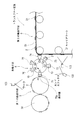
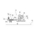
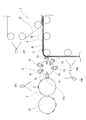
本例のトランスファー装置1は、図1に示すごとく、移載ワーク2を保持して搬送する第1の搬送手段3と、キャリアワーク21を保持して搬送する第2の搬送手段5と、第1の搬送手段3から移載ワーク2を受け取ると共に第2の搬送手段5のキャリアワーク21に移載するための移載手段6とを含むものである。
上記移載手段6は、同一円周上を周回して移載ワーク2を搬送するエンドエフェクタ71〜76を2以上有しており、該各エンドエフェクタ71〜76が少なくともいずれか他のエンドエフェクタとは独立に周回するように構成してある。
各エンドエフェクタ71〜76は、移載ワーク2を保持する保持面70sを備えており、かつ、各エンドエフェクタ71〜76の周回軸CL(図4参照。)に沿って保持面70sを進退させ得るように構成してある。
以下、この内容について詳しく説明する。Example 1
This example is an example relating to the transfer apparatus 1 that transfers the
As shown in FIG. 1, the transfer apparatus 1 of the present example includes a first transport unit 3 that holds and transports the
The transfer means 6 has two or
Each
Hereinafter, this content will be described in detail.
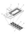
本例のトランスファー装置1は、RF−TAGを製造するためのものである。このトランスファー装置1は、図2に示すごとく、アンテナ41を形成したRF−TAG部品をキャリアワーク21とし、RF受発信処理用の電子部品を移載ワーク2として移載工程を実施するように構成してある。
The transfer apparatus 1 of this example is for manufacturing RF-TAG. As shown in FIG. 2, the transfer apparatus 1 is configured to perform the transfer process using the RF-TAG part on which the
キャリアワーク21は、材質PETよりなるフィルム部材の表面にアンテナ41を設けたものである。移載ワーク2は、RF受発信処理用のICを樹脂シートの表面に実装すると共に拡大電極を設けたインターポーザである。キャリアワーク21は、アンテナ41から延設した一対の端子42を設けてなり、該端子41の間に移載ワーク2を実装するように構成したものである。なお、本例では、キャリアワーク21に対する移載ワーク2の配置精度として数百ミクロンから数十ミクロンの精度を実現した。
The
上記第1の搬送手段3は、図1に示すごとく、略円柱状の回転体であり、その外周面に移載ワーク2を保持するように構成してある。この第1の搬送手段3は、隣接する移載ワーク供給装置30から移載ワーク2を受け取り、その後、移載ワーク2を移載手段6に引き渡すように構成してある。移載ワーク供給装置30は、移載ワーク2を保持した連続テープを略円柱状のローラで送り出すように構成してある。これに代えて、連続シート材料から移載ワーク2を個片に切り離して第1の搬送手段3に供給する個片化供給装置として移載ワーク供給装置30を構成することもできる。
As shown in FIG. 1, the first conveying means 3 is a substantially cylindrical rotating body, and is configured to hold the
第1の搬送手段3は、図1に示すごとく、点P1においてエンドエフェクタ(図中では、符号71のエンドエフェクタ)に移載ワーク2を引き渡すように構成してある。この第1の搬送手段3は、外表面に略一定間隔で移載ワーク2を保持するように構成してある。回転ローラよりなる第1の搬送手段3の表面には、図示しないポンプの吸引ポートに連通する孔(図示略)を設けてある。そして、第1の搬送手段3は、回転ローラの表面の孔を負圧にして移載ワーク2を吸着して保持する。一方、点P1では、回転ローラの表面の孔を正圧あるいは大気圧とすることで、移載ワーク2を開放する。なお、本例では、第1の搬送手段3は、それぞれ、図示しない駆動源及び駆動制御系によって略一定速度で動作するように制御されている。
As shown in FIG. 1, the first transport means 3 is configured to deliver the
上記第2の搬送手段5は、図1に示すごとく、コンベアベルト51を有している。そして、この第2の搬送手段5は、コンベアベルト51の表面に略一定間隔を空けてキャリアワーク21を保持して搬送するように構成してある。コンベアベルト51の表面には、図示しないポンプの吸引ポートに連通する孔(図示略)を設けてある。そして、第2の搬送手段5では、コンベアベルト51の表面の孔を負圧にしてキャリアワーク21を吸着して保持するように構成してある。なお、本例では、第2の搬送手段5は、それぞれ、図示しない駆動源及び駆動制御系によって略一定速度で動作するように制御されている。
The said 2nd conveyance means 5 has the
なお、本例では、個片状のキャリアワーク21をコンベアベルト51に保持して搬送した。これに代えて、ベルト状の保持部材に個片状のキャリアワーク21を保持させることも良く、印刷技術や写真技術等によりアンテナ41を連続的に設けた連続テープ状のフレキシブル基板に対して移載ワーク2を実装し、その後、個片化することも良い。
In this example, the
本例のトランスファー装置1は、第1の搬送手段3によって搬送中の移載ワーク2の搬送状態を撮影して、画像データを得るための撮像装置(計測部)103を有している。本例では、この画像データについて画像処理を施し、搬送中の移載ワーク2の搬送位置及び搬送速度を検出する。そして、図示しない制御手段は、検出した搬送位置及び搬送速度に基づいて、各エンドエフェクタ71〜76の周回運動を制御するように構成してある。
The transfer apparatus 1 of this example has an image pickup apparatus (measurement unit) 103 for photographing the transport state of the
さらに、本例のトランスファー装置1は、図1に示すごとく、エンドエフェクタ71〜76により保持された移載ワーク2の状態を撮影する撮像装置(計測部)106と、第2の搬送手段5における移載ワーク2の搬送状態を撮影する撮像装置(計測部)105とを備えている。撮像装置105、106により撮影した画像データに基づけば、例えば、移載ワーク2やキャリアワーク21の搬送間隔の異常、姿勢異常、異物の存在等の異常検出が可能である。
Further, as shown in FIG. 1, the transfer device 1 of the present example includes an imaging device (measurement unit) 106 that captures the state of the
特に、本例では、撮像装置103、105、106により得た画像データを基にして、後述する進退機構及び回転機構を制御した。なお、撮像手段103、105、106としては、CCD素子、CMOS素子を含むものや、低コストな光学式センサを含むものを適用することができる。
In particular, in this example, an advance / retreat mechanism and a rotation mechanism, which will be described later, are controlled based on image data obtained by the
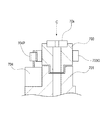
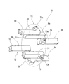
上記移載手段6は、同一の仕様の2つの移載手段6a、6bを組み合わせたものである。そして、各移載手段6a(6b)は、図3〜図5に示すごとく、3つの同軸回転体10を組み合わせて構成してある。移載手段6a(6b)は、図3及び図4に示すごとく、構造部材60a、60b、60cと、同軸上に配置された4つの軸受80、82、84、86とを有している。そして、各軸受80、82、84、86の内周側には、構造部材である中空軸60を配設してある。そして、この中空軸60の外周には、同軸回転体10の周回運動を支持するためのベアリング61、63、65を配設してある。
The transfer means 6 is a combination of two transfer means 6a and 6b having the same specifications. Each transfer means 6a (6b) is configured by combining three coaxial rotating
移載手段6a(6b)は、各同軸回転体10が互いに他の同軸回転体10を支持する構造を有する。具体的には、軸方向に隣り合う軸受のうち一方の内輪と、他方の外輪とを連結部材91、93、95を介して一体的に連結してある。そして、連結部材91、93、95を介して連結された内輪と外輪との組み合わせのうち、内輪の内周側に同軸回転体10が一体的に固定され、外輪に駆動ホイール92、94、96を外挿して固定してある。
The transfer means 6 a (6 b) has a structure in which each coaxial
上記のように構成した本例の移載手段6a(6b)では、周回軸CLを中心とした周方向における等間隔の3方向から上記3つの駆動ホイール92、94、96に回転駆動力を供給してある。これにより、各同軸回転体10の駆動ホイール92、94、96の軸心に向かう外圧を相殺している。また、上記移載手段6a(6b)では、各駆動ホイール92、94、96に対して、それぞれ独立に汎用サーボ制御系原動機(外部モータ)を結合してある。これにより、各同軸回転体10(エンドエフェクタ71、73、75(72、74、76))の周回運動の独立制御を可能としている。
In the transfer means 6a (6b) of the present example configured as described above, rotational driving force is supplied to the three
各同軸回転体10は、図5に示すごとく、それぞれ1つのエンドエフェクタを備えている。エンドエフェクタ71、73、75(72、74、76)は、図3及び図4に示すごとく、周回軸CLと略平行をなし、偏芯して配置された棒状材である。エンドエフェクタ71、73、75(72、74、76)は、周回軸CLの周りを周回可能なように回転支持されている。
Each coaxial
なお、本例の移載手段6a(6b)では、その構造上、駆動ホイール92、94、96の外周側が開放空間となっている。それ故、駆動ホイール92、94、96の外周側には、各種機構部を設けることができる。例えば、上記汎用サーボ制御系原動機に代えて、より高精度な制御が可能なダイレクトドライブ機構を設けることも良い。本例では、タイミングベルトにより回転駆動できるよう、駆動ホイール92、94、96の外周面に伝導用噛み合い溝(精密ギアー等)を設けてある。
In addition, in the transfer means 6a (6b) of this example, the outer peripheral side of the
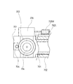
同軸回転体10は、図5及び図8に示すごとく、それぞれ1つのエンドエフェクタ71〜76を備えている。エンドエフェクタ71、73、75(72、74、76)は、図2及び図3に示すごとく、周回軸CLと略平行をなすよう、偏芯して配置した棒状材である。エンドエフェクタ71、73、75(72、74、76)は、周回軸CLの周りを周回可能なように回転支持されている。エンドエフェクタ71、73、75(72、74、76)は、図4に示すごとく、その先端部に、移載ワーク2(図1参照。)を吸着して保持するための保持面70sを有している。この保持面70sは、空気圧制御のための孔を設けてなり、移載ワーク2を負圧吸着して保持するように構成してある。一方、移載ワーク2を第2の搬送手段5に引き渡す際には、保持面70sの孔を大気圧又は正圧に調整した。なお、保持面70sの孔の圧力制御を実現するための構造については、後述する。
さらに、エンドエフェクタ71、73、75(72、74、76)は、図4に示すごとく、保持面70sを回転させるための回転機構及び、保持面70sを周回軸CLに沿って進退させるための進退機構を備えている。As shown in FIGS. 5 and 8, the coaxial
Further, as shown in FIG. 4, the
エンドエフェクタ71は、図5に示すごとく、その先端側(保持面70s側)がベアリング61の外輪61bの外周に固定されていると共に、後端側が軸受80の内輪80aの内周に固定されている。軸受80の内輪80aは、連結部材91を介して、軸方向に隣り合う軸受82の外輪82bと一体的に連結されている。外輪82bの外周側には、連結部材91の一部を介し駆動ホイール92が固定されている。
As shown in FIG. 5, the
エンドエフェクタ73は、図5に示すごとく、その先端側(保持面70s側)がベアリング63の外輪63bの外周に固定されていると共に、後端側が軸受82の内輪82aの内周に固定されている。軸受82の内輪82aは、連結部材93を介して、軸方向に隣り合う軸受84の外輪84bと一体的に連結されている。外輪84bの外周側には、連結部材93の一部を介し駆動ホイール94が固定されている。
As shown in FIG. 5, the
エンドエフェクタ75は、図5に示すごとく、その先端側(保持面70s側)がベアリング65の外輪65bの外周に固定されていると共に、後端側が軸受84の内輪84aの内周に固定されている。軸受84の内輪84aは、連結部材95を介して、軸方向に隣り合う軸受86の外輪86bと一体的に連結されている。外輪86bの外周側には、連結部材95の一部を介し駆動ホイール96が固定されている。
As shown in FIG. 5, the
進退機構は、図4及び図7に示すごとく、エンドエフェクタ71〜76の本体部分をなす支持部材702と、保持面70sを保持台座703を支持する摺動部材701と、該摺動部材701に固定したモータ705(図4では、モータ705を省略してある。)とを有する。摺動部材701は、支持部材702の内周の中空部に摺動可能なように挿入してある。支持部材702の外周面には、ラックギア702Lを設けてある。このラックギア702Lに対しては、モータ705の出力軸に嵌合したウォームギア705Wがギア係合している。そして、モータ705の回転制御により、摺動部材701の進退を制御できるようにしてある。
As shown in FIGS. 4 and 7, the advancing / retreating mechanism includes a supporting
回転機構は、図4、図6及び図7に示すごとく、保持面70sを有すると共に摺動部材701に回転可能に支持された保持台座703と、摺動部材701に固定したモータ704(図4では、モータ704を省略してある。)とを有する。保持台座703は、外周面にギア703Gを設けた略円板状の部材である。保持台座703のギア703Gに対しては、モータ704の出力軸に嵌合したギア704Pが係合している。そして、回転機構は、モータ704の回転制御により、保持台座703を回転させて保持面70sを回転させ得るように構成したものである。
4, 6, and 7, the rotation mechanism includes a holding
本例の搬送装置1では、図9に示すごとく、2つの移載手段6a、6bを組み合わせてある。移載手段6aは、エンドエフェクタ71、73、75を備えている。移載手段6bは、エンドエフェクタ72、74、76を備えている。そして、同図に示すごとく、すべてのエンドエフェクタ71〜76が同一円周上を周回するように、これら2つの移載手段6a、6bを対向配置してある。
In the transport apparatus 1 of this example, as shown in FIG. 9, two transfer means 6a and 6b are combined. The transfer means 6a includes
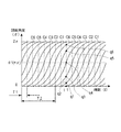
上記のように構成した移載手段6では、各エンドエフェクタ71〜76は、同一円周上を周回する。各エンドエフェクタ71〜76は、それぞれ互いの周回順序を維持しながら第1の搬送手段3の搬送動作に同期し、相対速度が略ゼロの状態で第1の搬送手段3からワーク2を受け取る。その後、各エンドエフェクタ71〜76は、第2の搬送手段5の搬送動作に同期し、相対速度が略ゼロの状態で第2の搬送手段5にワーク2を引き渡すように構成してある。
In the transfer means 6 configured as described above, the
各エンドエフェクタ71〜76は、同一円周上で周回運動を行い、受け取りと引き渡しを含む周回運動の間に、それぞれ独立に周期変速制御が行われる。具体的には、エンドエフェクタの周回軌道上において、ワーク2の受け取りと引き渡しのためのタイミング調整(周回位置調整)及び、その時の速度調整のため周期変速制御が行われる。
Each of the
次に、本例の同軸回転体における保持面70sの吸着機構(孔の圧力制御機構)について図1を用いて説明する。例えば、図1に示すトランスファー装置1の状態は、エンドエフェクタ71が第1の搬送手段3からワーク2を受け取る(回転位置Q1。)一方、エンドエフェクタ72、73が第2の搬送手段5に向けて移動中(回転位置Q2、Q3。)であり、エンドエフェクタ74が第2の搬送手段5に向けてワーク2を引き渡ししたところ(回転位置Q4。)である。また、エンドエフェクタ75、76は、移動回転中の状態(各回転位置Q5、Q6。)である。
Next, the adsorption mechanism (hole pressure control mechanism) of the holding
一方、上記移載手段6a(b)の中空軸60の端面には、図4に示すごとく、周回軸CLに沿って貫通孔70bを設けてある。そして、この貫通孔70bには、図示しないポンプの吸入ポートを接続してある。それ故、中空軸60の中空部は、上記ポンプの作用により負圧に維持される。また、中空軸60の外周壁面には、径方向に貫通する貫通孔70aを設けてある。さらに、ベアリング61、63、65には、上記貫通孔70aと連通するように、径方向に貫通してエンドエフェクタ71、73、75の中空部に連通する孔を設けてある。
On the other hand, as shown in FIG. 4, a through
特に、本例の貫通孔70aは、上記回転位置Q1(厳密には、回転位置Q1において保持面70sがワーク2を吸着するよう、Q1の手前の位置。)から上記回転位置Q4(厳密には、回転位置Q3において保持面70sがワーク2をリリースするよう、Q4の手前の位置。)までの周回区間に位置するエンドエフェクタに連通するよう、中空軸60の外周壁面における所定の周方向位置に設けてある。
In particular, the through-
一方、エンドエフェクタが回転位置Q4に位置したとき、ベアリング61の孔を介して大気圧が導入されるよう、中空軸60の外周壁面における所定の周方向位置に大気圧導入ポート(図示略)を設けてある。これにより、本例の移載手段6aでは、各エンドエフェクタ71、73、75の回転に伴うベアリング61、63、65の回転に応じて、保持面70sの孔の圧力制御が自動的に実施される。
On the other hand, when the end effector is positioned at the rotational position Q4, an atmospheric pressure introduction port (not shown) is provided at a predetermined circumferential position on the outer peripheral wall surface of the
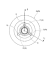
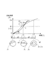
次に、エンドエフェクタ71〜76の周回運動について、図10を用いて説明する。図10は、エンドエフェクタ71〜76の回転角度の時間変化を示すものである。各曲線C1〜C6は、図1における各エンドエフェクタ71〜76の運動に対応している。また、時間t1におけるグラフ上の点q1〜q6は図1における回転位置Q1〜Q6に対応する。図1における第1の搬送手段3と、移載手段6とが接する位置(回転位置Q1)を回転角度θの原点とし、回転方向は図1に示すように反時計回りとする。
Next, the circular motion of the
図10における周期T1は、第1の搬送手段3が移載手段6に移載ワーク2を供給する周期(ワーク供給周期)である。なお、このワーク供給周期は、第1の搬送手段3の搬送速度と、コンベアベルト31上の移載ワーク2の間隔により決定される周期である。また、周期T2は、各エンドエフェクタが周回する周期である。短時間ではT2≒6×T1の関係が成立し、長時間における平均ではT2=6×T1である。本例では、独立に回転制御される6つのエンドエフェクタ71〜76を用いている。それ故、本例の移載手段6では、個々のエンドエフェクタの周回速度に対して約6倍のワーク供給速度に対応可能である。
A cycle T1 in FIG. 10 is a cycle (work supply cycle) in which the first transport unit 3 supplies the
ここで、エンドエフェクタ71を例にして、その周回運動について説明する。図11は、エンドエフェクタ71の周回運動における回転角度の時間変化を示している。エンドエフェクタ71は、時刻t=t1、回転角度θ=0のとき、速度V1で移載ワーク2を第1の搬送手段3から受け取る。そして、時刻t=t2、回転角度θ=θ1(=π)のとき、速度V2で移載ワーク2を第2の搬送手段5に引き渡す。その後、時刻t=t3(=t1+T2)、回転角度2πにおいて初期回転位置に復帰する。
Here, the circular motion of the
時間区間a1、a3、a5は、移載ワーク2の受け取りあるいは、引き渡しのため、第1の搬送手段3の搬送動作あるいは、第2の搬送手段5の搬送動作に同期した区間である。これらの時間区間では、移載ワーク2の搬送速度との相対速度略ゼロとするよう、速度を略一定に保持する区間である。一方、時間区間a2、a4は、エンドエフェクタ71の回転速度を増速あるいは、減速するための区間である。
The time sections a1, a3, and a5 are sections synchronized with the transfer operation of the first transfer means 3 or the transfer operation of the second transfer means 5 for receiving or transferring the
また、この時間区間a2、a4においては、速度調整の他に周回位置の調整が行われる。この周回位置調整は、図11に示すごとく、例えば、第2の搬送手段5による搬送速度が変動した場合に実施される。第2の搬送手段5の搬送速度が変動したときに一定の搬送間隔を維持するためには、移載手段6から第2の搬送手段5に移載ワーク2を引き渡すタイミングを調整する必要がある。そこで、このタイミングを調整するために、各エンドエフェクタ71〜76の周回位置の制御が実施される。
Further, in the time sections a2 and a4, the rotation position is adjusted in addition to the speed adjustment. As shown in FIG. 11, the rotation position adjustment is performed, for example, when the transport speed by the
例えば、時間△tだけ早めに移載ワーク2を引き渡す必要が発生した場合には、エンドエフェクタ71の速度を増速することにより、図11に示す曲線が点fに代えて点f1を通るようにする。これにより、第2の搬送手段5の略一定の搬送間隔を維持し得る所定の位置に、移載ワーク2を精度良く移載することができる。
For example, when the
次に、上記回転機構及び上記進退機構の制御について説明する。制御手段は、撮像手段105により得た画像データを処理して、第2の搬送手段5における目標移載位置を認識する。その一方、撮像手段106により得た画像データを処理して、移載手段6の各保持面70sに保持された個々の移載ワーク2の周回軸CL(図4参照。)方向の位置及び、姿勢を認識する。
Next, control of the rotation mechanism and the advance / retreat mechanism will be described. The control means processes the image data obtained by the imaging means 105 and recognizes the target transfer position in the second transport means 5. On the other hand, the image data obtained by the imaging means 106 is processed, and the position of each
本例のトランスファー装置1の制御手段は、目標移載位置のうちの周回軸CL方向の位置と、移載ワーク2の周回軸CL方向の位置とから、保持面70sの進退制御量を計算する。また、制御手段は、移載ワーク2の姿勢に基づいて、上記回転機構による移載ワーク2の回転制御量を計算する。そして、制御手段は、計算した進退制御量に基づいてモータ705を制御すると共に、計算した回転制御量に基づいてモータ704を制御する。
The control means of the transfer apparatus 1 of this example calculates the advance / retreat control amount of the holding
以上のように、本例の搬送装置1は、各エンドエフェクタ71〜76の周回運動を独立に回転制御することにより高速かつ高精度の移載を実現することができる。本例のトランスファー装置1では、回転機構及び進退機構を上記のように制御することで、一層、精度良く移載ワーク2を移載することができる。
As described above, the transfer device 1 of the present example can realize high-speed and high-accuracy transfer by independently controlling the rotational movement of the
本例のトランスファー装置1によれば、移載ワーク2を停止させることなく連続して搬送しながらキャリアワーク21上に移載ワーク2を配置できる。それ故、製造精度の高いRF−TAGを大量かつ低コストに製造することができる。なお、本例のトランスファー装置1は、RF−TAG部品の製造に限らず、例えばICカード部品への電子部品の移載や実装にも用いることができる。ここで、例えば、RF−TAG用のICそのものを上記移載ワーク2とすることもできる。さらに、紙おむつや、生理用品などのサニタリー製品の製造工程に用いる生産設備として、本例のトランスファー装置1を利用することもできる。
According to the transfer device 1 of this example, the
なお、本例のトランスファー装置1は、各種のコンバーティングマシン、印刷機、ラベニラー、半導体製造装置等に利用することができる。例えば、紙おむつや、サニタリーナプキンや、タンポンや、フェイスマスクの製造工程に適用することができる。さらに、シールであるラベルを移載ワーク2とし、サニタリー製品やスナック菓子等の食品などの各種の製品をキャリアワーク21として、ラベル貼り付けを行うこともできる。さらには、サニタリー製品やスナック菓子等の食品などの各種の製品を移載ワーク2として、包装用フィルムをキャリアワーク21とすれば、製品の包装を行うことができる。
In addition, the transfer apparatus 1 of this example can be used for various converting machines, printing machines, rabenillas, semiconductor manufacturing apparatuses, and the like. For example, it can be applied to the manufacturing process of paper diapers, sanitary napkins, tampons, and face masks. Further, labeling can be performed by using a label as a seal as the
さらに、本例では、個片化されたキャリアワーク21を用いたが、これに代えて、個片化前のシート状の長尺材料を利用することもできる。そして、この場合には、シート状の長尺材料の表面に目標移載位置を指示するマーカーを付しておき、このマーカーを画像認識することも良い。この場合には、マーカーが指示する目標移載位置に基づいてエンドエフェクタ71〜76の周回運動を制御することで、連続シート上のキャリアワーク21に対して精度高く移載ワーク2を移載することができる。なお、RF−TAGを製造する場合において、アンテナパターンを複数形成した長尺シート状のキャリアワーク21では、アンテナパターンを画像認識のためのマーカーとして利用することができる。すなわち、上記マーカーとしては、キャリアワーク21の表面に現れる図柄を利用することができる。
Furthermore, although the
(実施例2)
本例は、実施例1のトランスファー装置を基にして、保持面70sの進退機構及び回転機構の構成を変更した例である。この内容について、図12及び図13を用いて説明する。(Example 2)
This example is an example in which the structures of the advance / retreat mechanism and the rotation mechanism of the holding
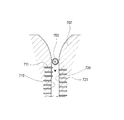
本例のトランスファー装置1は、エンドエフェクタ71〜76の摺動部材701を摺動させるためのガイド部材707を有している。このガイド部材707は、周回回転する保持台座703の周回軸CL方向の位置を規制するガイド溝707mを有している。このガイド部材707は、周回軸CLに沿って進退可能なように構造部材60bに保持されている。そして、エンドエフェクタ71〜76の保持台座703の周回軸CL方向の位置を、ガイド溝707mの位置に略一致させるように作用する。なお、本例では、構造部材60bに配設した図示しないモータにより、ガイド部材707の周回軸CL方向の位置を制御している。
The transfer device 1 of this example includes a
ガイド部材707は、エンドエフェクタ71〜76の周回位置におけるQ1とQ4(図1参照。)との間の区間に、ガイド溝707mが位置するように配設される。また、ガイド溝707mは、周回方向の上流側であるQ1に向けて広く開口する湾曲形状を呈している。本例の移載手段6においては、この湾曲形状と保持台座703との当接により、摺動部材701が周回軸CL方向に進退し、保持台座703の周回軸CL方向の位置が変更される。そして、これにより、保持面70sの周回軸CL方向の位置が変更される。
The
ガイド溝707mにおける対面する内周面710、720には、図13に示すごとく、それぞれ、ガイド溝707mに向けて適宜突出するよう、それぞれ独立して空気圧制御された突出ピン711、721を複数、配置してある。一方、本例の保持台座703は、摺動部材701に対して、1刻み0.5度のラチェット機構を介して回転支持してある。
As shown in FIG. 13, the inner
第1の内周面710から突出する各突出ピン711によれば、ラチェット機構を介して回転支持された保持台座703を1刻みずつ時計回り方向に回転することができる。また、第2の内周面720から突出する各突出ピン721によれば、保持台座703を1刻みずつ反時計周りに回転することができる。
According to the protruding
すなわち、本例の移載機構6の回転機構では、各内周面710、720から突出させる突出ピン711、721の本数に応じて、保持台座703の回転位置を制御している。そして、保持台座703の回転位置を制御することで、保持面70sの回転位置を変更している。
That is, in the rotation mechanism of the
なお、その他の構成及び作用効果については、実施例1と同様である。また、各突出ピン711、721の突出機構としては、本例の空気圧制御に代えて、油圧制御や、ソレノイド(電磁駆動)による制御などの各種の駆動機構を採用することができる。
Other configurations and operational effects are the same as those in the first embodiment. Further, as the protruding mechanism of each
(実施例3)
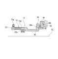
本例は、実施例1のトランスファー装置を基にして、キャリアワーク21を連続シート体に変更すると共に、ラミネートフィルム22を送り出す機構を追加した例である。この内容について、図14を用いて説明する。
本例では、移載ワーク2を配置したキャリアワーク21の表面に、ラミネートフィルム22を接合する。ラミネートフィルム22によれば、製品の表面保護効果を得ると共に対候性を向上することができる。このとき、ラミネートフィルム22に位置合わせ用のマーカー等を付しておくのも良い。この場合には、撮像装置107を用い、ラミネートフィルム22上のマーカーを画像認識することで、キャリアワーク21との精度の高い位置合わせが可能になる。なお、撮像装置107としては、CCD素子やCMOS素子のほか、低コストな光学式のセンサを適用することも可能である。(Example 3)
This example is an example in which a
In this example, the
なお、その他の構成及び作用効果については、実施例1と同様である。
さらに、キャリアワーク21として紙おむつの生地をなす不織布よりなる連続体(連続シート材料)を適用し、このキャリアワーク21にセットするワーク2としてパルプよりなる吸水性パッドを適用することもできる。この場合には、ラミネートフィルム22に柄模様をプリントすることで、紙おむつの意匠効果を高めることができる。さらに、柄模様を利用してラミネートフィルム22とキャリアワーク21との位置合わせを行うこともできる。すなわち、撮像装置107を用いてラミネートフィルム22の絵柄を認識することで、その送り位置を検出し、ラミネートフィルム22とキャリアワーク21との精度の良い位置合わせを実現することができる。Other configurations and operational effects are the same as those in the first embodiment.
Further, a continuous body (continuous sheet material) made of a nonwoven fabric forming a cloth of a paper diaper can be applied as the
さらになお、移載ワーク2をスナック菓子等とし、キャリアワーク21及びラミネートフィルム22をポリエチレン等の樹脂フィルムとするのも良い。この場合には、相互に対面させたフィルム状のキャリアワーク21とラミネートフィルム22えの縁部を接合することで、袋状の包装を施すことができる。
Furthermore, the
Claims (10)
上記移載手段は、同一円周上を周回して上記移載ワークを搬送するエンドエフェクタを2以上有しており、該各エンドエフェクタが少なくともいずれか他の上記エンドエフェクタとは独立に周回するように構成してあり、
上記各エンドエフェクタは、上記移載ワークを保持する保持面と、上記保持面に保持された移載ワークの状態を撮像する撮像装置により得られた画像データを基にして制御され、上記各エンドエフェクタの周回軸に沿って上記保持面を進退させ得る進退機構とを備えたことを特徴とするトランスファー装置。The first transfer means for holding and transferring the transfer work, the second transfer means for holding and transferring the carrier work, and the transfer work from the first transfer means are received and transferred to the carrier work. A transfer device including transfer means for mounting,
The transfer means has two or more end effectors that circulate on the same circumference and convey the transfer work, and each end effector circulates independently of at least one of the other end effectors. It is configured as
Each end effector is controlled on the basis of a holding surface that holds the transfer workpiece and image data obtained by an imaging device that images the state of the transfer workpiece held on the holding surface. A transfer device comprising: an advance / retreat mechanism capable of advancing and retreating the holding surface along the rotation axis of the effector.
上記移載手段は、同一円周上を周回して上記移載ワークを搬送するエンドエフェクタを2以上有しており、該各エンドエフェクタが少なくともいずれか他の上記エンドエフェクタとは独立に周回するように構成してあり、
上記各エンドエフェクタは、上記移載ワークを保持する保持面と、上記保持面に保持された移載ワークの状態を撮像する撮像装置により得られた画像データを基にして制御され、保持面をその法線方向の中心軸周りに回転させる回転機構とを備えることを特徴とするトランスファー装置。The first transfer means for holding and transferring the transfer work, the second transfer means for holding and transferring the carrier work, and the transfer work from the first transfer means are received and transferred to the carrier work. A transfer device including transfer means for mounting,
The transfer means has two or more end effectors that circulate on the same circumference and convey the transfer work, and each end effector circulates independently of at least one of the other end effectors. It is configured as
Each of the end effectors is controlled based on image data obtained by a holding surface that holds the transfer workpiece and an image pickup device that captures the state of the transfer workpiece held on the holding surface . A transfer device comprising: a rotation mechanism that rotates around a central axis in the normal direction.
該制御手段は、上記第1の搬送手段から上記ワークを受け取る際の上記エンドエフェクタの周回速度が上記第1の搬送手段の搬送速度に略一致するように制御し、かつ、上記第2の搬送手段に上記ワークを引き渡す際の上記エンドエフェクタの周回速度が上記第2の搬送手段の搬送速度に略一致するように制御するように構成されていることを特徴とするトランスファー装置。In Claim 1 or Claim 3 , the said transfer device has a control means for controlling the circumference speed and circumference position at the time of each said end effector making a round motion,
The control means controls so that the circulating speed of the end effector when receiving the workpiece from the first conveying means substantially coincides with the conveying speed of the first conveying means, and the second conveying means. A transfer apparatus configured to control the rotation speed of the end effector when delivering the work to the means so as to substantially coincide with the conveyance speed of the second conveyance means.
上記各軸受のうち軸方向の中間に配置された1又は2以上の中間軸受の上記内輪が、隣り合う他の上記軸受の上記外輪と連結され一体的に回転するように構成してあると共に上記同軸回転体のいずれかを一体的に保持しており、
上記各軸受のうち軸方向の端部に配置された上記軸受のうちの一方は、上記内輪が隣り合う他の上記軸受の上記外輪と連結され一体的に回転するように構成してあると共に上記同軸回転体のいずれかを一体的に保持しており、かつ、上記外輪が上記移載手段の構造部材に固定されており、
上記各軸受のうち軸方向の端部に配置された上記軸受のうちの他方は、上記外輪が隣り合う他の上記軸受の上記内輪と連結され一体的に回転するように構成してあり、かつ、上記内輪が上記移載手段の構造部材に固定されており、
上記各外輪のうち、隣り合う上記軸受の上記内輪と一体的に連結された上記外輪は、それぞれ、独立に回転制御される外部モータの出力軸に連結してあることを特徴とするトランスファー装置。 4. The transfer means according to claim 1, wherein the transfer means rotates a coaxial rotating body integrally holding one or more end effectors that circulate integrally, and at least two or more coaxial rotating bodies. Three or more bearings that are coaxially arranged adjacent to each other in the axial direction so as to support each of the bearings. Each of the bearings has a substantially cylindrical inner ring, and a substantially cylindrical shape that is arranged to be extrapolated to the inner ring. An outer ring, and a bearing mechanism that enables relative rotation between the inner ring and the outer ring,
Among the bearings, the inner ring of one or more intermediate bearings arranged in the middle in the axial direction is connected to the outer ring of another adjacent bearing and is configured to rotate integrally. One of the coaxial rotating bodies is held together,
One of the bearings arranged at the axial end of each of the bearings is configured so that the inner ring is connected to the outer ring of another adjacent bearing and is rotated integrally. One of the coaxial rotating bodies is integrally held, and the outer ring is fixed to the structural member of the transfer means,
The other of the bearings arranged at the end in the axial direction among the bearings is configured such that the outer ring is connected to the inner ring of another adjacent bearing and is rotated integrally. The inner ring is fixed to the structural member of the transfer means,
Of the outer rings, the outer ring integrally connected to the inner ring of the adjacent bearing is connected to an output shaft of an external motor that is independently rotationally controlled.
Priority Applications (1)
| Application Number | Priority Date | Filing Date | Title |
|---|---|---|---|
| JP2006536403A JP4838136B2 (en) | 2004-09-22 | 2005-09-21 | Transfer device |
Applications Claiming Priority (4)
| Application Number | Priority Date | Filing Date | Title |
|---|---|---|---|
| JP2004275061 | 2004-09-22 | ||
| JP2004275061 | 2004-09-22 | ||
| JP2006536403A JP4838136B2 (en) | 2004-09-22 | 2005-09-21 | Transfer device |
| PCT/JP2005/017422 WO2006033370A1 (en) | 2004-09-22 | 2005-09-21 | Transfer apparatus |
Publications (2)
| Publication Number | Publication Date |
|---|---|
| JPWO2006033370A1 JPWO2006033370A1 (en) | 2008-05-15 |
| JP4838136B2 true JP4838136B2 (en) | 2011-12-14 |
Family
ID=36090127
Family Applications (1)
| Application Number | Title | Priority Date | Filing Date |
|---|---|---|---|
| JP2006536403A Expired - Lifetime JP4838136B2 (en) | 2004-09-22 | 2005-09-21 | Transfer device |
Country Status (7)
| Country | Link |
|---|---|
| US (1) | US7721872B2 (en) |
| EP (1) | EP1801046B1 (en) |
| JP (1) | JP4838136B2 (en) |
| CN (1) | CN101018722B (en) |
| DE (1) | DE602005020330D1 (en) |
| TW (1) | TW200616873A (en) |
| WO (1) | WO2006033370A1 (en) |
Families Citing this family (32)
| Publication number | Priority date | Publication date | Assignee | Title |
|---|---|---|---|---|
| DK1947037T3 (en) * | 2007-01-17 | 2009-11-23 | Fameccanica Data Spa | Device for changing the relationship between articles being transported and turning these articles |
| DE102009010191A1 (en) * | 2009-02-23 | 2010-08-26 | Kolbus Gmbh & Co. Kg | Bookbinding machine |
| FR2945237B1 (en) * | 2009-05-06 | 2016-06-03 | Cer | MACHINE AND METHOD FOR MARKING OR LABELING |
| US8100253B2 (en) * | 2009-06-30 | 2012-01-24 | The Procter & Gamble Company | Methods and apparatuses for transferring discrete articles between carriers |
| US8813351B2 (en) | 2011-12-20 | 2014-08-26 | Kimberly-Clark Worldwide, Inc. | Apparatus and method for applying discrete parts to a moving web |
| US8636136B2 (en) | 2011-12-20 | 2014-01-28 | Kimberly-Clark Worldwide, Inc. | Apparatus and method for rotatably conveying and applying discrete parts to a substrate |
| US8820513B2 (en) | 2012-04-16 | 2014-09-02 | The Procter & Gamble Company | Methods for transferring discrete articles |
| US8833542B2 (en) | 2012-04-16 | 2014-09-16 | The Procter & Gamble Company | Fluid systems and methods for transferring discrete articles |
| US8720666B2 (en) | 2012-04-16 | 2014-05-13 | The Procter & Gamble Company | Apparatuses for transferring discrete articles |
| US8607959B2 (en) | 2012-04-16 | 2013-12-17 | The Procter & Gamble Company | Rotational assemblies and methods for transferring discrete articles |
| CN102849458B (en) * | 2012-09-21 | 2014-11-05 | 浙江工业大学 | Pneumatic automatic box laying-down device |
| EP2911629A1 (en) | 2012-10-23 | 2015-09-02 | The Procter & Gamble Company | Methods for transferring discrete articles onto a web |
| WO2014102856A1 (en) * | 2012-12-25 | 2014-07-03 | 平田機工株式会社 | Transfer system |
| US9763370B2 (en) | 2013-03-15 | 2017-09-12 | National Technology & Engineering Solutions Of Sandia, Llc | Apparatus for assembly of microelectronic devices |
| US9463942B2 (en) | 2013-09-24 | 2016-10-11 | The Procter & Gamble Company | Apparatus for positioning an advancing web |
| TW201604534A (en) * | 2014-07-18 | 2016-02-01 | 亞亞科技股份有限公司 | High efficiency conveying module of inspection system |
| CN104261327A (en) * | 2014-09-19 | 2015-01-07 | 江苏仅一包装技术有限公司 | Rotary lifting device |
| US9511952B1 (en) | 2015-06-23 | 2016-12-06 | The Procter & Gamble Company | Methods for transferring discrete articles |
| US9511951B1 (en) | 2015-06-23 | 2016-12-06 | The Procter & Gamble Company | Methods for transferring discrete articles |
| CN107709202A (en) * | 2015-07-02 | 2018-02-16 | 新兴机械株式会社 | Conveyer |
| JP5975556B1 (en) * | 2015-12-11 | 2016-08-23 | 上野精機株式会社 | Transfer equipment |
| JP6312270B2 (en) * | 2016-03-25 | 2018-04-18 | 株式会社写真化学 | Electronic device manufacturing method and device using device chip |
| WO2018011905A1 (en) | 2016-07-13 | 2018-01-18 | 株式会社瑞光 | Conveying device and method for manufacturing disposable wearable article using same |
| CN106313879B (en) * | 2016-08-10 | 2017-08-29 | 京东方科技集团股份有限公司 | Transfer apparatus and printing transferring method |
| US20200165079A1 (en) * | 2018-11-27 | 2020-05-28 | Dishcraft Robotics, Inc. | Dishwashing Conveyance System And Method |
| JP6788922B1 (en) * | 2020-01-10 | 2020-11-25 | 上野精機株式会社 | Electronic component processing equipment |
| KR102796435B1 (en) * | 2020-05-14 | 2025-04-16 | 엘지전자 주식회사 | An Intelligent assembling and transferring integrated apparatus for semiconductor light emitting device |
| AR118939A1 (en) * | 2020-05-15 | 2021-11-10 | Marisa Rosana Lattanzi | COMBINED MACHINE TO PRODUCE LAMINAR SEPARATORS FOR PRODUCTS CONTAINED IN BOXES AND DRAWERS |
| TWI766335B (en) * | 2020-08-07 | 2022-06-01 | 鴻勁精密股份有限公司 | Alignment platform and electronic component transmission apparatus |
| CN112278862B (en) * | 2020-10-13 | 2022-09-27 | 南京多脉智能设备有限公司 | Friction-free pneumatic type glass panel carrier manipulator |
| JP7251721B1 (en) * | 2022-12-26 | 2023-04-04 | 上野精機株式会社 | Parts processing equipment |
| CN119429620B (en) * | 2025-01-08 | 2025-05-30 | 山东康舜日用品有限公司 | Conveying device for paper diaper production |
Citations (4)
| Publication number | Priority date | Publication date | Assignee | Title |
|---|---|---|---|---|
| WO2001044086A1 (en) * | 1999-12-16 | 2001-06-21 | Zuiko Corporation | Method and device for transportation |
| JP2002214289A (en) * | 2001-01-17 | 2002-07-31 | Nec Machinery Corp | Leadless semiconductor element pickup device |
| JP2003137420A (en) * | 2001-11-02 | 2003-05-14 | Sekisui House Ltd | Material feeding control conveyor device |
| JP2004265920A (en) * | 2003-02-07 | 2004-09-24 | Hallys Corp | Small-piece transfer device capable of random-cycle shifting |
Family Cites Families (45)
| Publication number | Priority date | Publication date | Assignee | Title |
|---|---|---|---|---|
| US2860760A (en) * | 1955-06-17 | 1958-11-18 | Sylvania Electric Prod | Lamp bulb loader |
| US3986920A (en) | 1972-04-12 | 1976-10-19 | Johnson Matthey & Co., Limited | Transfer application device |
| US3946931A (en) | 1974-11-27 | 1976-03-30 | Western Electric Company, Inc. | Methods of and apparatus for bonding an article to a substrate |
| US4080053A (en) | 1975-11-03 | 1978-03-21 | Xerox Corporation | Transfer apparatus and method |
| US4372802A (en) | 1980-06-02 | 1983-02-08 | Tokyo Denki Kagaku Kogyo Kabushiki Kaisha | Apparatus for mounting chip type circuit elements on printed circuit boards |
| IT1188972B (en) * | 1980-12-12 | 1988-01-28 | Gd Spa | TRANSFER DEVICE FOR BAR-SHAPED ITEMS |
| US4548668A (en) | 1983-01-10 | 1985-10-22 | Continental Can Company, Inc. | Combination machine for assembling container components |
| CA1217572A (en) | 1983-05-02 | 1987-02-03 | Kenichi Saito | Mounting apparatus for chip type electronic parts |
| US4915565A (en) | 1984-03-22 | 1990-04-10 | Sgs-Thomson Microelectronics, Inc. | Manipulation and handling of integrated circuit dice |
| US4617082A (en) * | 1984-11-19 | 1986-10-14 | Kimberly-Clark Corporation | Method and apparatus for applying discrete strips to a web of material |
| US4767487A (en) * | 1985-10-18 | 1988-08-30 | Kimberly-Clark Corporation | Method for repositioning discrete articles |
| US5045148A (en) | 1986-10-15 | 1991-09-03 | Ga-Vehren Engineering Co. | Article attaching apparatus |
| SE462333B (en) | 1987-01-23 | 1990-06-11 | Moelnlycke Ab | DEVICE FOR TRANSFER OF ARTICLES FROM A FIRST TO ANOTHER TRANSPORT ROAD |
| US4893982A (en) | 1987-09-17 | 1990-01-16 | Taiho Seiki Co., Ltd. | Apparatus for conveying workpiece |
| US5000806A (en) | 1988-04-19 | 1991-03-19 | Paper Converting Machine Company | Method and apparatus for applying an elastic strand to a disposable diaper |
| JPH07109957B2 (en) | 1988-06-21 | 1995-11-22 | 松下電器産業株式会社 | Electronic component mounting method |
| US5025910A (en) | 1990-02-02 | 1991-06-25 | Curt G. Joa, Inc. | Rotary pad turner |
| US5268724A (en) | 1990-04-20 | 1993-12-07 | Fuji Xerox Co., Ltd. | Transfer apparatus providing improved transfer material guidance along a feed path to an electrophotographic image carrier |
| US5222854A (en) | 1991-09-09 | 1993-06-29 | Leland D. Blatt | Automatic tool changer |
| CA2050023C (en) | 1991-04-22 | 2002-03-05 | Kimberly-Clark Worldwide, Inc. | Elongated element comprising helically patterned adhesive |
| TW199259B (en) | 1991-09-26 | 1993-02-01 | Nippon Tobacco Sangyo Kk | |
| US5275685A (en) | 1991-11-07 | 1994-01-04 | Ferag Ag | Apparatus for gluing attachment slips to printed products |
| US5150164A (en) | 1991-12-16 | 1992-09-22 | Eastman Kodak Company | Transfer apparatus |
| US5389173A (en) | 1992-12-02 | 1995-02-14 | Paper Converting Machine Company | Apparatus and process for making disposable diaper type products |
| JPH0826437A (en) | 1994-07-11 | 1996-01-30 | Fuji Photo Film Co Ltd | Method and apparatus for transferring workpiece |
| WO1996029521A1 (en) | 1995-03-17 | 1996-09-26 | Hitachi, Ltd. | Bearing assembly, spindle motor and actuator using the same bearing assembly, and magnetic disk device |
| JP2708016B2 (en) | 1995-06-14 | 1998-02-04 | 松下電器産業株式会社 | Electronic component automatic mounting equipment |
| US6334248B1 (en) | 1996-09-20 | 2002-01-01 | Total Register, Inc. | Apparatus and method for the continuous high speed rotary application of stamping foil |
| JPH10145091A (en) | 1996-11-08 | 1998-05-29 | Matsushita Electric Ind Co Ltd | Electronic component mounting equipment |
| US5882474A (en) | 1997-06-13 | 1999-03-16 | B&H Manufacturing Company, Inc. | Labeling machine with radial motion turret |
| IT1298357B1 (en) | 1997-12-02 | 2000-01-05 | Gd Spa | DEVICE AND METHOD FOR THE APPLICATION OF REMOVABLE COUPONS IN SUBSTANTIALLY PARALLELEPIPED PACKAGES. |
| US6471802B1 (en) | 1998-12-07 | 2002-10-29 | Gerro Plast Gmbh | Labeling apparatus and method |
| US6656312B1 (en) | 1999-01-16 | 2003-12-02 | The Procter & Gamble Company | Apparatus and process for applying discrete portions of a web material onto receiving web |
| DE19922873A1 (en) * | 1999-05-19 | 2000-11-23 | Krones Ag | Bottle conveyor for moving bottles into and out of treatment chamber has rotor and pairs of star wheels arranged around its circumference with gripping devices and transfer component to transfer bottles between them |
| DE19925343A1 (en) | 1999-06-02 | 2000-12-07 | Schuler Pressen Gmbh & Co | Transfer facility |
| US6672448B2 (en) | 2000-03-10 | 2004-01-06 | Aida Engineering Co., Ltd. | Transfer device |
| US6883576B1 (en) | 2000-10-18 | 2005-04-26 | Accraply/Trine Ca | Quick change roll-fed high speed labeling system and methods for using same |
| US6648122B1 (en) * | 2000-10-25 | 2003-11-18 | Curt G. Joa, Inc. | Apparatus for transferring articles |
| JP3798298B2 (en) | 2000-12-01 | 2006-07-19 | 株式会社瑞光 | Rotating device, method for conveying worn article, and method for conveying web |
| US6604623B2 (en) * | 2001-01-31 | 2003-08-12 | Zuiko Corporation | Article transfer apparatus |
| US6913664B2 (en) | 2001-05-23 | 2005-07-05 | Zuiko Corporation | Method and apparatus for producing disposable worn article |
| JP4269612B2 (en) | 2002-09-18 | 2009-05-27 | 株式会社Ihi | Transfer press work transfer device |
| US7097725B2 (en) | 2002-10-16 | 2006-08-29 | Zuiko Corporation | Placement device |
| JP4012042B2 (en) | 2002-11-01 | 2007-11-21 | 株式会社瑞光 | Wearing article manufacturing equipment |
| ITBO20030471A1 (en) | 2003-08-01 | 2005-02-02 | Gd Spa | METHOD AND DEVICE FOR THE APPLICATION OF A LABEL TO A PACKAGE. |
-
2005
- 2005-09-21 JP JP2006536403A patent/JP4838136B2/en not_active Expired - Lifetime
- 2005-09-21 CN CN2005800302354A patent/CN101018722B/en not_active Expired - Fee Related
- 2005-09-21 DE DE602005020330T patent/DE602005020330D1/en not_active Expired - Lifetime
- 2005-09-21 TW TW094132709A patent/TW200616873A/en not_active IP Right Cessation
- 2005-09-21 EP EP05785968A patent/EP1801046B1/en not_active Expired - Lifetime
- 2005-09-21 US US11/575,738 patent/US7721872B2/en not_active Expired - Lifetime
- 2005-09-21 WO PCT/JP2005/017422 patent/WO2006033370A1/en not_active Ceased
Patent Citations (4)
| Publication number | Priority date | Publication date | Assignee | Title |
|---|---|---|---|---|
| WO2001044086A1 (en) * | 1999-12-16 | 2001-06-21 | Zuiko Corporation | Method and device for transportation |
| JP2002214289A (en) * | 2001-01-17 | 2002-07-31 | Nec Machinery Corp | Leadless semiconductor element pickup device |
| JP2003137420A (en) * | 2001-11-02 | 2003-05-14 | Sekisui House Ltd | Material feeding control conveyor device |
| JP2004265920A (en) * | 2003-02-07 | 2004-09-24 | Hallys Corp | Small-piece transfer device capable of random-cycle shifting |
Also Published As
| Publication number | Publication date |
|---|---|
| JPWO2006033370A1 (en) | 2008-05-15 |
| WO2006033370A1 (en) | 2006-03-30 |
| EP1801046A1 (en) | 2007-06-27 |
| US7721872B2 (en) | 2010-05-25 |
| TWI353956B (en) | 2011-12-11 |
| US20080023296A1 (en) | 2008-01-31 |
| EP1801046A4 (en) | 2008-12-24 |
| TW200616873A (en) | 2006-06-01 |
| DE602005020330D1 (en) | 2010-05-12 |
| CN101018722A (en) | 2007-08-15 |
| CN101018722B (en) | 2011-09-07 |
| EP1801046B1 (en) | 2010-03-31 |
Similar Documents
| Publication | Publication Date | Title |
|---|---|---|
| JP4838136B2 (en) | Transfer device | |
| JP4691217B2 (en) | Transport device | |
| JP3739752B2 (en) | Small-piece transfer device capable of random-cycle shifting | |
| US7488619B2 (en) | Method and apparatus for manufacturing IC chip packaged device | |
| JP2002198690A (en) | Component supplying device of surface mounting machine | |
| CN110970321A (en) | Chip mounting equipment and chip mounting method | |
| JP5234929B2 (en) | Transfer equipment | |
| JP3505920B2 (en) | Label winding method and apparatus for cylindrical battery | |
| JP5710238B2 (en) | Electronic component mounting equipment | |
| TW202013259A (en) | Electronic component mounting device and method for manufacturing electronic component mounted body | |
| JP5226525B2 (en) | Expander unit, and electronic component manufacturing apparatus including the expander unit | |
| JP2013077772A (en) | Manufacturing apparatus for electronic component packaging body | |
| JP2968595B2 (en) | Work mounting device | |
| TW201801900A (en) | Article transfer apparatus which can stably transfer articles and change the intervals between articles even when articles such as IC wafers are transported at a high speed | |
| JPH0236666Y2 (en) | ||
| JPH03274800A (en) | Work carrying method | |
| JP2007035745A (en) | Electronic component holding and transferring mechanism |
Legal Events
| Date | Code | Title | Description |
|---|---|---|---|
| RD02 | Notification of acceptance of power of attorney |
Free format text: JAPANESE INTERMEDIATE CODE: A7422 Effective date: 20090706 |
|
| A131 | Notification of reasons for refusal |
Free format text: JAPANESE INTERMEDIATE CODE: A131 Effective date: 20100824 |
|
| A521 | Request for written amendment filed |
Free format text: JAPANESE INTERMEDIATE CODE: A523 Effective date: 20101020 |
|
| A02 | Decision of refusal |
Free format text: JAPANESE INTERMEDIATE CODE: A02 Effective date: 20110215 |
|
| A521 | Request for written amendment filed |
Free format text: JAPANESE INTERMEDIATE CODE: A523 Effective date: 20110512 |
|
| A911 | Transfer to examiner for re-examination before appeal (zenchi) |
Free format text: JAPANESE INTERMEDIATE CODE: A911 Effective date: 20110609 |
|
| TRDD | Decision of grant or rejection written | ||
| A01 | Written decision to grant a patent or to grant a registration (utility model) |
Free format text: JAPANESE INTERMEDIATE CODE: A01 Effective date: 20110913 |
|
| A01 | Written decision to grant a patent or to grant a registration (utility model) |
Free format text: JAPANESE INTERMEDIATE CODE: A01 |
|
| A61 | First payment of annual fees (during grant procedure) |
Free format text: JAPANESE INTERMEDIATE CODE: A61 Effective date: 20110929 |
|
| FPAY | Renewal fee payment (event date is renewal date of database) |
Free format text: PAYMENT UNTIL: 20141007 Year of fee payment: 3 |
|
| R150 | Certificate of patent or registration of utility model |
Free format text: JAPANESE INTERMEDIATE CODE: R150 Ref document number: 4838136 Country of ref document: JP Free format text: JAPANESE INTERMEDIATE CODE: R150 |
|
| R250 | Receipt of annual fees |
Free format text: JAPANESE INTERMEDIATE CODE: R250 |
|
| R250 | Receipt of annual fees |
Free format text: JAPANESE INTERMEDIATE CODE: R250 |
|
| R250 | Receipt of annual fees |
Free format text: JAPANESE INTERMEDIATE CODE: R250 |
|
| S111 | Request for change of ownership or part of ownership |
Free format text: JAPANESE INTERMEDIATE CODE: R313113 |
|
| R350 | Written notification of registration of transfer |
Free format text: JAPANESE INTERMEDIATE CODE: R350 |
|
| S111 | Request for change of ownership or part of ownership |
Free format text: JAPANESE INTERMEDIATE CODE: R313113 |
|
| R350 | Written notification of registration of transfer |
Free format text: JAPANESE INTERMEDIATE CODE: R350 |
|
| S111 | Request for change of ownership or part of ownership |
Free format text: JAPANESE INTERMEDIATE CODE: R313113 |
|
| R350 | Written notification of registration of transfer |
Free format text: JAPANESE INTERMEDIATE CODE: R350 |
|
| R250 | Receipt of annual fees |
Free format text: JAPANESE INTERMEDIATE CODE: R250 |
|
| S201 | Request for registration of exclusive licence |
Free format text: JAPANESE INTERMEDIATE CODE: R314201 |
|
| R350 | Written notification of registration of transfer |
Free format text: JAPANESE INTERMEDIATE CODE: R350 |
|
| S111 | Request for change of ownership or part of ownership |
Free format text: JAPANESE INTERMEDIATE CODE: R313113 |
|
| R350 | Written notification of registration of transfer |
Free format text: JAPANESE INTERMEDIATE CODE: R350 |
|
| R250 | Receipt of annual fees |
Free format text: JAPANESE INTERMEDIATE CODE: R250 |
|
| R250 | Receipt of annual fees |
Free format text: JAPANESE INTERMEDIATE CODE: R250 |
|
| R250 | Receipt of annual fees |
Free format text: JAPANESE INTERMEDIATE CODE: R250 |
|
| R250 | Receipt of annual fees |
Free format text: JAPANESE INTERMEDIATE CODE: R250 |
|
| R250 | Receipt of annual fees |
Free format text: JAPANESE INTERMEDIATE CODE: R250 |
|
| R250 | Receipt of annual fees |
Free format text: JAPANESE INTERMEDIATE CODE: R250 |
|
| R250 | Receipt of annual fees |
Free format text: JAPANESE INTERMEDIATE CODE: R250 |
|
| EXPY | Cancellation because of completion of term |