JP4810746B2 - Group III nitride compound semiconductor device - Google Patents
Group III nitride compound semiconductor device Download PDFInfo
- Publication number
- JP4810746B2 JP4810746B2 JP2001101990A JP2001101990A JP4810746B2 JP 4810746 B2 JP4810746 B2 JP 4810746B2 JP 2001101990 A JP2001101990 A JP 2001101990A JP 2001101990 A JP2001101990 A JP 2001101990A JP 4810746 B2 JP4810746 B2 JP 4810746B2
- Authority
- JP
- Japan
- Prior art keywords
- electrode
- seat
- auxiliary
- auxiliary electrode
- compound semiconductor
- Prior art date
- Legal status (The legal status is an assumption and is not a legal conclusion. Google has not performed a legal analysis and makes no representation as to the accuracy of the status listed.)
- Expired - Fee Related
Links
Images


Landscapes
- Led Devices (AREA)
Description
【0001】
【産業上の利用分野】
本発明はIII族窒化物系化合物半導体素子に関する。例えば、青色系発光ダイオードなどのIII族窒化物系化合物半導体発光素子の電極の改良として好適な発明である。
【0002】
【従来の技術】
青色系発光ダイオードなどのIII族窒化物系化合物半導体発光素子においては、素子の全面から均一な発光を得るため種々の提案がなされている。
例えば、特開平8−340131号公報や特開平10−117017号公報では、pコンタクト層の上面にp補助電極を放射状に設けて、pコンタクト層に対する注入電流密度の均一化を図っている。また、例えば特開平10−275934号公報に示されるように、p型コンタクト層の上面に透光性電極を貼ってその上にp台座電極を設けるものもある。この例では、p台座電極から素子の辺に沿ってp補助電極が延設されている。
素子の角部に形成されたn台座電極から素子の辺に沿ってn補助電極を設けた例が特開平9−97922号公報や特開2000-22210号公報に開示されている。
【0003】
【発明が解決しようとする課題】
本発明者らの検討によれば、高い輝度が要求されかつ同色の発光ダイオードを集合して使用する信号機等においては、使用する発光ダイオードのチップサイズを大きくすることが望ましいことがわかった。チップサイズを大きくすることで使用個数が削減されれば、発光ダイオードの組付け工数が小さくなって製造コストの削減となることはもとより、各発光ダイオードへ電流を均一に分配するための回路設計が容易かつ簡素になるからである。
本発明者らは、したがって、発光ダイオードのチップサイズを大きくすべく検討を重ねてきた。その結果、次なる課題を見出すに至った。
【0004】
発光ダイオードにおけるnコンタクト層(n電極の形成される層)の抵抗が比較的高いためn電極から遠い部分まで十分に電流が行き渡らず、当該部分での発光が低下する。一方、n電極に近い部分では強い発光が得られるため、素子全体でみれば発光が不均一となる。かかる点から従来の小型の素子(300〜400μm□)を見てみると、n電極から遠く離れた部分では多少暗くなっているが、かかる部分がごく小さい領域であることから当該発光の不均一は実質上大きな障害とならなかった。
チップサイズが大きくなると、単位発光面積当たりに注入される好適な電流密度を確保しようとしたとき、p台座電極に印加する電流量を大きくしなければならない。p台座電極に印加された電流はこのp台座電極から透光性電極へ流入することとなるが、電流量が大きくなるとp台座電極と透光性電極との間で焼きつき(発生するジュール熱により接合部の透光性電極が焼き切れてしまうこと)の発生する可能性が高くなる。p台座電極に注入可能な電流量(許容電流量)を決める一つの要因にp台座電極と透光性電極との界面の面積があり、当該面積が大きければ大きいほど許容電流量を大きくできると考えられる。
また、最外径が700μm以上の大型のチップにおいて、有効発光面に好適な電流密度を確保しようとしたときには1つのp台座電極と1つのn台座電極の組み合わせでは、ボンディングワイヤー部での発熱によりモールド樹脂が焼きついたり、ボンディングワイヤ自体が熱により断線してしまうという不具合の生じる惧れがある。
【0005】
【課題を解決するための手段】
この発明は、上記課題の少なくとも一つを解決すべくなされたものである。即ち、最外径が700μm以上の素子において、n電極から最も離れたp電極の点までの距離が500μm以内にある、ことを特徴とするIII族窒化物系化合物半導体素子。
【0006】
このように構成されたIII族窒化物系化合物半導体素子によれば、n電極から最も離れたp電極の点が上記距離内にあるので、n型半導体層の抵抗が高くても、n電極から最も離れた素子の部分へも電子が十分に注入される(電流が拡散する)。その結果、素子の全面がより均等に発光する。
なお、電流密度と発光素子の発光出力との関係は、電流密度が所定の値を超えたところで発光出力が飽和してくる。即ち、当該所定の値を超えた電流密度を注入してもそれに見合った発光出力の増加が得られない。したがって、高い発光出力でかつ高い発光効率を達成しようとすれば、当該所定の値の近傍の電流密度を素子の全域で達成することが好ましい。この発明のようにn電極とp電極との距離を規定すれば素子の全域で当該好適な電流密度を得ることができ、もって発光効率の優れた素子を提供できることとなる。
【0007】
なお、この明細書において、n電極はn台座電極とこれから延長されるn補助電極から構成され、p電極はp台座電極及びp台座電極から延長されたp補助電極から構成される。また、素子の最外径とは、素子を平面から見たときに素子上に引ける最長の直線の長さであり、素子が矩形の場合は対角線の長さが最外径となる。素子がひし形の場合も同様である。素子が円形、楕円径の場合は中心を通る直線である。このように、素子の形状は特に限定されるものではない。上記のほかに六角形、八角形等の多角形の素子形状を採用することも可能である。
n電極とこれから最も離れたp電極との間の距離の更に好ましい上限は400μmであり、更に更に好ましくは350μmである。
かかる構成は、矩形チップの場合、一辺の長さが500μm以上(最外径では700μm以上)のチップに適用されることが好ましい。このようにチップサイズが大きくなると、従来のようなn電極構成では、これから距離の離れて十分な電流密度が得られずに暗くなってしまう部分が容認できないほどに大きな領域となり、かつその領域が素子の中央部分に現出して発光態様を不適なものとする惧れがある。更に好ましくは、矩形チップの場合、一辺の長さが600μm以上であり、更に更に好ましくは一辺の長さが700μm以上であり、最も好ましくは800μm以上である。
【0008】
このようにp電極の任意の点とn電極との距離を所定の範囲内に収めるために、この発明の一の局面ではn台座電極からn補助電極を素子の中央部分へ延設する構成を採用する。
素子の中央部分にn補助電極が存在することにより、当該n補助電極と素子の全ての角部までの距離が一定になる。これにより、角部での発光出力の低下を防止できることとなる。
上記のようにしてn電極を改良してn型半導体層に対する電流の均一拡散を確保したところ、次の課題が新たに浮かび上がってきた。
p型半導体層の上に透光性電極を貼って電流の拡散を図るタイプにおいても、チップサイズが拡大してp台座電極又はp補助電極からの距離が大きくなると、薄膜である透光性電極自体の抵抗が無視できなくなり、p台座電極又はp補助電極から離れた部分のp型半導体層へ十分に電流を注入できなくなる。
【0009】
そこでこの発明の一の局面では、透光性電極上の任意の点とp台座電極又はp補助電極との距離を0〜1000μmの範囲内とした。
このように構成されたIII族窒化物系化合物半導体素子によれば、透光性電極の全ての点がp台座電極又はp補助電極から上記距離内にあるので、p台座電極又はp補助電極から最も離れた透光性電極の部分へも電流が十分に拡散され、その下のp型半導体層へ注入される。その結果、素子の全面が実質的に均等に発光する。透光性電極上の任意の点とp台座電極又はp補助電極との更に好ましい距離の上限は500μmであり、更に更に好ましくは450μmであり、更に更に更に好ましくは400μmであり、最も好ましくは350μmである。
かかる構成は、矩形チップの場合、一辺の長さが500μm以上(最外径では700μm以上)のチップに適用されることが好ましい。このようにチップサイズが大きくなると、従来のようなp電極構成では、これから距離の離れて十分な電流密度が得られずに暗くなってしまう部分が無視できないほど大きな領域となり、かつその部分が素子の中央に現出して発光態様を不適なものとする惧れがある。更に好ましくは、矩形チップの場合、一辺の長さが600μm以上であり、更に更に好ましくは一辺の長さが700μm以上であり、最も好ましくは800μm以上である。
【0010】
このように透光性電極上の任意の点とp台座電極又はp補助電極との距離を所定の範囲内に収めるために、この発明の一の局面ではp台座電極からp補助電極を透光性電極の中央部分へ延設する構成を採用する。
透光性電極の中央部分にp補助電極が存在することにより、当該p補助電極と透光性電極の全ての角部までの距離が一定になる。これにより、角部での発光出力の低下を防止できることとなる。
【0011】
上記構成のn電極とp電極をともに備えるIII族窒化物系化合物半導体素子においては、素子を平面から見たとき、n補助電極とp補助電極とがくし状に配置されることが好ましい。n補助電極とp補助電極の有る部分では素子は動作しない(発光素子では発光しない)ので、これらをくし状に配置することにより当該非動作部分を素子において対称乃至規則的なパターンで配置できることとなる。よって、素子の利用が容易になる。発光素子の場合は光を均一に外部へ取り出し易くなる。
【0012】
上記構成のn電極とp電極をともに備えるIII族窒化物系化合物半導体素子においては、素子を平面から見たとき、n補助電極とp補助電極とが相互に平行に配置される部分を含むことが好ましい。n補助電極とp補助電極の有る部分では素子は動作しない(発光素子では発光しない)ので、平行な部分を配置することにより当該非動作部分を素子において対称乃至規則的なパターンで配置できることとなる。よって、素子の利用が容易になる。発光素子の場合は光を均一に外部へ取り出し易くなる。
【0013】
チップサイズが大きくなると、素子による消費電力が大きくなるので、台座電極に印加される電流が大きくなる。従来のように台座電極がp側及びn側それぞれ1つであると、ボンディングワイヤー部での発熱によりモールド樹脂が焼きついたり、ボンディングワイヤ自体が熱により断線してしまうという問題が生じかねない。そこでこの発明の他の局面ではp台座電極とn台座電極とをそれぞれ複数設けることとした。これにより、上記の問題が解消される。
複数のp台座電極及びn台座電極を設けることが好ましいチップサイズは、矩形チップの場合、一辺の長さが500μm以上(最外径では700μm以上)のものである。更に好ましくは、一辺の長さが600μm以上であり、更に更に好ましくは一辺の長さが700μm以上であり、最も好ましくは800μm以上である。
【0014】
発光素子のチップサイズを大きくしてその消費電力が増大した場合には、上記の課題に加えて、p台座電極と透光性電極との間の焼きつきの問題がある。そのため、p台座電極からp補助電極をすることが好ましい。p補助電極を備えることにより、p台座電極及びp補助電極と透光性電極との間に充分な面積が得られ、もって焼きつきの発生が防止される。これにより、p台座電極に印加できる電流量(許容電流量)が増大し、素子の全面を発光させるために必要な電流量が充分確保できることとなる。
【0015】
以下、この発明を構成する各要素につき、III族窒化物系化合物半導体発光素子を例に採り、詳細に説明する。
n電極は半導体層をエッチングして表出されたnコンタクト層に形成される。n型のIII族窒化物系化合物半導体との間にオーム接触の得られるものであれば、その材質は任意に選択できるが、バナジウム・アルミニウム合金などのアルミニウム合金を採用することが好ましい。
n電極の形状も任意であるが、この発明の一局面にしたがって、p電極の任意の点からn電極までの距離を一定範囲内に収めるようにするには、n台座電極とこれから延設されたn補助電極との組合わせが好適である。n台座電極は素子の一辺のほぼ中央に配置しても、素子の角部に配置しても良い。n補助電極はn台座電極から素子の中央部分へ伸びる部分を有することが好ましい。
【0016】
n補助電極はn台座電極と同一材料でかつ同一方法(同一のマスク)により形成することが工数削減の見地から好ましい。この場合、n補助電極とn台座電極とは同一厚さとなる。
n補助電極とn台座電極とを別個に形成することもできる。この場合、n補助電極の材質及び厚さをn台座電極のそれと異ならせることもできる。
n台座電極は導電性ワイヤを周知の方法でボンデングするために十分な面積を有すればその形状は特に限定されない。
n補助電極は半導体層を除去した部分に形成されるので、有効半導体層の面積を極大化する見地からその幅を狭くすることが好ましい。n補助電極の幅は1〜40μmとすることがこのましい。更に好ましくは2〜30μmであり、更に更に好ましくは3〜25μmであり、更に更に更に好ましくは3〜20μmであり、最も好ましくは5〜15μmである。
【0017】
透光性電極の形成材料は特に限定されるものではないが、例えば下側から第1電極層としてCo層及び第2電極層としてAu層を順次積層する。
第1電極層の構成元素は第2電極層の構成元素よりもイオン化ポテンシャルが低い元素であり、第2電極層の構成元素は半導体に対するオーミック性が第1電極層の構成元素よりも良好な元素とするのが望ましい。p型コンタクト層と合金を形成するために、この電極層に対しても熱処理が施されるが、その熱処理により、半導体の表面から深さ方向の元素分布は、第2電極層の構成元素の方が第1電極層の構成元素よりも深く浸透した分布となる。即ち、電極層の元素分布が電極層の形成時の分布に対して反転している。電極層の形成後には、上側に形成した第2電極層の構成元素の方が下側になり、下側に形成した第1電極層の構成元素の方が上側に存在する。
望ましくは、第1電極層の構成元素は、ニッケル(Ni)、コバルト(Co)、鉄(Fe)、銅(Cu)、クロム(Cr)、タンタル(Ta)、バナジウム(V)、マンガン(Mn)、アルミニウム(Al)、銀(Ag)のうち少なくとも一種の元素であり、その膜厚は0.5〜15nmとする。第2電極層の構成元素は、パラジウム(Pd)、金(Au)、イリジウム(Ir)、白金(Pt)のうち少なくとも1種の元素であり、その膜厚は3.5〜25nmとする。最も望ましくは、第1電極層の構成元素はCoであり、第2電極層の構成元素はAuである。この場合には、熱処理により、半導体の表面から深さ方向の元素分布は、CoよりもAuが深く浸透した分布となる。
【0018】
p台座電極の形成材料も特に限定されるものではないが、例えば下側から第1金属層としてV層、第2金属層としてAu層及び第3金属層としてAl層を順次積層する構造とする。
第1金属層はその下の層と強固に結合できるように、第2の金属層よりもイオン化ポテンシャルが低い元素とする。第2の金属層はAl又はAuとのボンディング性が良好で、かつ透光性電極と反応しない元素とする。第3金属層は保護膜と強固に結合できる元素とすることが好ましい。
望ましくは、第1金属層の構成元素は、ニッケル(Ni)、鉄(Fe)、銅(Cu)、クロム(Cr)、タンタル(Ta)、バナジウム(V)、マンガン(Mn)、コバルト(Co)のうち少なくとも一種の元素であり、その膜厚は1〜300nmである。
望ましくは、第3金属層の構成元素は、アルミニウム(Al)、ニッケル(Ni)、チタン(Ti)のうち少なくとも一種の元素であり、その膜厚は1〜30nmである。
望ましくは、第2金属層の構成元素は金(Au)であり、その膜厚は0.3〜3μmである。
【0019】
p補助電極はp台座電極と同一材料でかつ同一方法(同一のマスク)により形成することが工数削減の見地から好ましい。この場合、p補助電極とp台座電極とは同一厚さとなる。
p補助電極とp台座電極とを別個に形成することもできる。この場合、p補助電極の材質及び厚さをp台座電極のそれと異ならせることもできる。
p台座電極は導電性ワイヤを周知の方法でボンデングするために十分な面積を有すればその形状は特に限定されない。ボンディング時の位置確認のためには、p台座電極としてn台座電極と異なる形状を採用することが好ましい。
p補助電極は光を遮蔽するので、その幅を狭くすることが好ましい。p補助電極の幅は1〜40μmとすることがこのましい。更に好ましくは2〜30μmであり、更に更に好ましくは3〜25μmであり、更に更に更に好ましくは3〜20μmであり、最も好ましくは5〜15μmである。
p台座電極及び/又はp補助電極の周囲に凹凸を設けて、透光性電極との間の接触面積を増大させることが好ましい。
p台座電極の周面は傾斜していることが好ましい。台座電極の周面をテ−パ状としておくことにより、台座電極及び透光性電極の表面に形成される保護膜(SiO2膜等)を当該テ−パ状部にもほぼ設計膜厚通りに形成することが可能となる。
【0020】
透光性電極の任意の点からp台座電極又はp補助電極までの距離を一定範囲内に収めるようにするには、p台座電極とこれから延設されたp補助電極との組み合わせが好適である。p台座電極は素子の一辺のほぼ中央に配置しても、素子の角部に配置しても良い。
p補助電極はn補助電極に対してくし状に形成することが好ましい。ここにくし状とは、素子を平面から見たときp補助電極とn補助電極とが互い違いに配置されている状態をいう。
また、p補助電極はn補助電極に対して平行に配置される部分を備えることが好ましい。
【0021】
透光性電極とp台座電極及びp補助電極を合金化するための熱処理は酸素を含むガス中において行うことが好ましい。このとき、酸素を含むガスとしては、O2、O3、CO、CO2、NO、N2O、NO2、又は、H2Oの少なくとも1種又はこれらの混合ガスを用いることができる。又は、O2、O3、CO、CO2、NO、N2O、NO2、又は、H2Oの少なくとも1種と不活性ガスとの混合ガス、又は、O2、O3、CO、CO2、NO、N2O、NO2、又は、H2Oの混合ガスと不活性ガスとの混合ガスを用いることができる。要するに酸素を含むガスは、酸素原子、酸素原子を有する分子のガスの意味である。
熱処理時の雰囲気の圧力は、熱処理温度において、窒化ガリウム系化合物半導体が熱分解しない圧力以上であれば良い。酸素を含むガスは、O2ガスだけを用いた場合には、窒化ガリウム系化合物半導体の分解圧以上の圧力で導入すれば良く、他の不活性ガスと混合した状態で用いた場合には、全ガスを窒化ガリウム系化合物半導体の分解圧以上の圧力とし、O2ガスは全ガスに対して10-6程度以上の割合を有しておれば十分である。要するに、酸素を含むガスは極微量存在すれば十分である。尚、酸素を含むガスの導入量の上限値は、p型低抵抗化及び電極合金化の特性からは、特に、制限されるものではない。要は、製造が可能である範囲まで使用できる。
熱処理に関しては、最も望ましくは、500〜600℃である。500℃以上の温度で、抵抗率が完全に飽和した低抵抗のp型窒化ガリウム系化合物半導体を得ることができる。又、600℃以下の温度において、電極の合金化処理を良好に行うことができる。又、望ましい温度範囲は、450〜650℃である。
p台座電極、p補助電極、透光性電極の形成材料及び熱処理条件については、特開平9−320984号公報、特開平10−209493号公報を参照されたい。
【0022】
この明細書において、III族窒化物系化合物半導体は一般式としてAlXGaYIn1−X−YN(0≦X≦1、0≦Y≦1、0≦X+Y≦1)で表され、AlN、GaN及びInNのいわゆる2元系、AlxGa1−xN、AlxIn1−xN及びGaxIn1−xN(以上において0<x<1)のいわゆる3元系を包含する。III族元素の一部をボロン(B)、タリウム(Tl)等で置換しても良く、また、窒素(N)の一部もリン(P)、ヒ素(As)、アンチモン(Sb)、ビスマス(Bi)等で置換できる。III族窒化物系化合物半導体層は任意のドーパントを含むものであっても良い。n型不純物として、Si、Ge、Se、Te、C等を用いることができる。p型不純物として、Mg、Zn、Be、Ca、Sr、Ba等を用いることができる。なお、p型不純物をドープした後にIII族窒化物系化合物半導体を電子線照射、プラズマ照射若しくは炉による加熱にさらすことも可能である。III族窒化物系化合物半導体層の形成方法は特に限定されないが、有機金属気相成長法(MOCVD法)のほか、周知の分子線結晶成長法(MBE法)、ハライド気相成長法(HVPE法)、スパッタ法、イオンプレーティング法、電子シャワー法等によっても形成することができる。
ここにIII族窒化物系化合物半導体素子には、発光ダイオード、受光ダイオード、レーザダイオード、太陽電池等の光素子の他、整流器、サイリスタ及びトランジスタ等のバイポーラ素子、FET等のユニポーラ素子並びにマイクロウェーブ素子などの電子デバイスを挙げられる。また、これらの素子の中間体としての積層体にも本発明は適用されるものである。
なお、発光素子の構成としては、MIS接合、PIN接合やpn接合を有したホモ構造、ヘテロ構造若しくはダブルへテロ構造のものを用いることができる。発光層として量子井戸構造(単一量子井戸構造若しくは多重量子井戸構造)
を採用することもできる。
【0023】
【実施例】
以下、この発明の実施例について説明する。
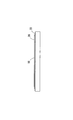
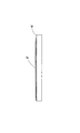
実施例は発光ダイオード10であり、その構成を図1に示す。なお、図1は層の構成を説明するための図であり、各層の厚さや幅のプロポーションを正確に反映するものではない。
【0024】

n型クラッド層3は発光層4側の低電子濃度n-層とバッファ層2側の高電子濃度n+層とからなる2層構造とすることができる。後者はn型コンタクト層と呼ばれる。
発光層4は超格子構造のものに限定されない。発光素子の構成としてはシングルへテロ型、ダブルへテロ型及びホモ接合型のものなどを用いることができる。
発光層4とp型クラッド層5との間にマグネシウム等のアクセプタをドープしたバンドギャップの広いIII族窒化物系化合物半導体層を介在させることもできる。これは発光層4中に注入された電子がp型クラッド層5に拡散するのを防止するためである。
p型クラッド層5を発光層4側の低ホール濃度p−層と電極側の高ホール濃度p+層とからなる2層構造とすることができる。後者はp型コンタクト層と呼ばれる。
上記構成の発光ダイオードにおいて、各III族窒化物系化合物半導体層は一般的な条件でMOCVDを実行して形成する。
【0026】
次に、マスクを形成してp型クラッド層5、活性層4及びn型クラッド層3の一部を反応性イオンエッチングにより除去し、n電極9を形成すべきn電極形成面11を表出させる。
【0027】
ウエハの全面に、蒸着装置にて、Co層(1.5nm)とAu層(60nm)を順次積層する。次に、フォトレジストを一様に塗布して、フォトリソグラフィにより、n電極形成面11及びその周囲からほぼ10μm幅の部分(クリアランス領域13)でフォトレジストを除去して、エッチングによりその部分の透光性電極形成材料を除去し、半導体層を露出させる。その後、フォトレジストを除去する。
次に、リフトオフ法により、V層(17.5nm)、Au層(1.5μm)及びAl層(10nm)を順次蒸着積層してp台座電極7及びp補助電極7(p電極7)とする。
バナジウムとアルミニウムとからなるn電極9も同様にリフトオフ法により形成される。
【0028】
上記のようにして得られた試料を加熱炉に入れ、炉内を1Pa以下にまで排気し、その後10数PaまでO2を供給する。そして、その状態で炉の温度を550℃に設定して、4分間程度、熱処理する。これにより、透光性電極6とp台座電極及びp補助電極とはそれぞれの材料が合金化されるとともに、両者は結合してp電極となる。
本発明者らの検討によれば、p台座電極及びp補助電極の直下において電流はp型クラッド層へほとんど注入されていない。これは、p台座電極及びp補助電極の直下において透光性電極を構成するAu/Co蒸着層に上述したような分布の反転が生じないためにコンタクト抵抗が比較的高くなっているためであると予想される。したがって、p台座電極及びp補助電極の周面と透光性電極6との界面が両者の有効な電気的接続面となる。即ち、p台座電極に印加された電流はp台座電極及びp補助電極の周面より透光性電極へ流れ、ここで全面に拡散されてp型半導体層の全面へ均等に注入される。
p台座電極上のワイヤーボンディング等を施す領域並びにn電極上面及びその周縁部以外のほぼ全面にかけて絶縁性でかつ透光性の保護膜14(酸化シリコン、窒化シリコン、酸化チタン、酸化アルミニウム等)が被覆される。保護膜14の形成方法にはスパッタ法或いはCVD法を採用できる。
【0029】
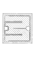
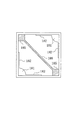
このようにして得られた発光素子10の電極配置の一例を図2〜図11に示した。図2において、符号16は透光性電極、符号17はp台座電極、符号18はp補助電極を示す。p補助電極18はp台座電極17と一体的に形成されている。p台座電極17は一の辺の中央に配置されており、このp台座電極17を中心にしてp補助電極18は上向きE字形状である。符号15は保護膜の見切りラインである。
n台座電極19はp台座電極17の対向する辺のほぼ中央に形成されている。n補助電極20はn台座電極19と一体的に形成されている。n補助電極20はn台座電極を中心として下向きコ字形状であり、n補助電極20はp補助電極18と平行にかつくし状に配置されている。
符号21はn電極形成面、符号22はダイシングのために表出した基板材料面である。保護膜24は図7において斜線で示してある。
この素子は一辺の長さが1000μmの正方形である。
【0030】
他の発光素子23の電極配置例を図12〜図20に示した。図12において、符号26は透光性電極、符号27はp台座電極、符号28はp補助電極を示す。p補助電極28はp台座電極27と一体的に形成されている。p台座電極27は一の辺の中央に配置されており、このp台座電極27を中心にしてp補助電極28は上向きコ字形状である。符号25は保護膜の見切りラインである。
n台座電極29はp台座電極27の対向する辺のほぼ中央に形成されている。n補助電極30はn台座電極29と一体的に形成されている。n補助電極30はn台座電極からp台座電極27に向けて延出されている。
符号31はn電極形成面、符号32はダイシングのために表出した基板材料面である。保護膜34は図17において斜線で示してある。
この素子は一辺の長さが600μmの正方形である。
【0031】
他の発光素子33の電極配置例を図21〜図30に示した。図21において、符号36は透光性電極、符号37はp台座電極、符号38はp補助電極を示す。p補助電極38はp台座電極37と一体的に形成されている。p台座電極37は一の辺の両端にそれぞれ配置されており、p補助電極28は上向きE字形状である。符号35は保護膜の見切りラインである。
n台座電極39はp台座電極37の対向する辺に形成されている。n補助電極40はn台座電極39と一体的に形成されている。n補助電極40は下向きコ字形状であり、n補助電極40の付け根部分にn台座電極39が配置されている。n補助電極40はp補助電極38と平行にかつくし状に配置されている。
符号41はn電極形成面、符号42はダイシングのために表出した基板材料面である。保護膜34は図26において斜線で示してある。
この素子は一辺の長さが1000μmの正方形である。
【0032】
他の発光素子43の電極配置例を図31に示した。図31において、符号46は透光性電極、符号47はp台座電極、符号48はp補助電極を示す。p補助電極48はp台座電極47と一体的に形成されている。p台座電極47は対向する角部に配置されており、p補助電極48は各p台座電極47、47から図中素子の上辺及び左側辺にそって形成されている。符号45は保護膜の見切りラインである。
n台座電極49は素子の一つの角部に形成されている。n補助電極50はn台座電極49と一体的に形成されている。n補助電極50はn台座電極49から素子の中央部分に向けて形成され、対向する角部の近くまで伸びている。
符号51はn電極形成面、符号52はダイシングのために表出した基板材料面である。
この素子は一辺の長さが800μmの正方形である。
【0033】
図32に図31の変形態様を示した。図32の素子43−1では、n補助電極50−1に枝50−2、50−3が形成されている。各枝50−2、50−3はそれぞれp台座電極47、47に向けて伸びている。
図32において、図31と同一の要素には同一の符号を附してその説明を省略する。
【0034】
他の発光素子53の電極配置例を図33に示した。図33において、符号56は透光性電極、符号57はp台座電極、符号58はp補助電極を示す。p補助電極58はp台座電極57と一体的に形成されている。p台座電極57は対向する角部に配置されており、p補助電極58は各p台座電極47、47から図中素子の上辺及び下辺にそって形成されている。符号55は保護膜の見切りラインである。
n台座電極59は素子の中央部分に形成されている。n補助電極60はn台座電極59と一体的に形成されている。n補助電極60はn台座電極59からp補助電極58と平行に形成され、素子のエッジ近くまで伸びている。
符号61はn電極形成面、符号62はダイシングのために表出した基板材料面である。
この素子は一辺の長さが800μmの正方形である。
【0035】
他の発光素子63の電極配置例を図34に示した。図34において、符号66は透光性電極、符号67はp台座電極を示す。この例ではp補助電極が省略されている。p台座電極67は対向する角部に配置されている。符号55は保護膜の見切りラインである。
n台座電極69は素子の中央部分に形成されている。n補助電極70はn台座電極69と一体的に形成されている。n補助電極70はn台座電極69からp台座電極のない素子の角部へ向けて伸びている。
符号71はn電極形成面、符号72はダイシングのために表出した基板材料面である。
この素子は一辺の長さが800μmの正方形である。
【0036】
発光素子の他の電極配置例を図35〜図52に示す。これらの図例においては説明の簡素化のため、p電極とn電極(斜線で示してある)のみが示されている。図35〜図52の図例においても、図34以前の図例で説明したように、透光性電極がp型半導体層のほぼ全面に貼られており、p電極は当該透光性電極の上に形成されたものである。n電極形成面や保護膜の図示も省略されているが、これらも以前の例と同様にして形成されているものである。また、以下の説明においては、単に説明の都合上のために、図面を基準にして要素の位置関係(上下左右)を規定する。
これらの例の発光素子の一辺の長さも500μm以上である。
【0037】
図35の例では、p台座電極81、81が素子のあい対向する角部に形成され、このp台座電極81、81からそれぞれ側辺にそってp補助電極82、82が形成されている。n台座電極85、85は素子における残りのあい対向する角部に形成され、このn台座電極85、85から上辺及び下辺に沿ってn補助電極86、86が形成されている。
【0038】
図36の例では、p台座電極91が素子の一つの角部に形成され、このp台座電極91から素子の左辺及び下辺に沿った第1のp補助電極92と上辺に沿った第2のp補助電極93とが形成されている。n台座電極95は右辺のほぼ中央に配置され、そこからn補助電極96が素子の中央部分へ延設されている。
【0039】
図37の例では、p台座電極101、101が素子の上二つの角部に形成され、各p台座電極101、101からく字状に折れ曲がったp補助電極102、102が延設されている。n台座電極105は下側の2つの角部に形成され、各n台座電極105から左右の辺にそって第1の補助電極106、106がたちあがっている。第2の補助電極107は逆T字形であり、下辺から素子の中心を通って上辺まで達している。下辺中央からたちあがる部分はp補助電極102、102と平行となる。
【0040】
図38の例では、p台座電極111は素子の中央部に形成され、これからp補助電極112、112が一の対角線上に伸びている。n台座電極115、115は素子のあい対向する角部に形成される。n補助電極116、116はこの2つのn台座電極115,115を繋ぐように、素子の周辺にそって形成されている。
【0041】
図39の例では、p台座電極121が左辺の中央やや下側に設けられ、これから第1のp補助電極122が左辺に沿って下って下辺に延びている。左下隅から下辺に対する挟角をほぼ30度として第2のp補助電極123が延びている。n台座電極125が右辺の中央やや上側に設けられ、これから第1のn補助電極126が右辺に沿ってたちあがり上辺に延びている。右上隅から上辺に対する挟角をほぼ30度として第2のp補助電極127が延びている。
【0042】
図40の例では、p台座電極131が左辺の略中央に形成され、これから第1のp補助電極132が左辺に沿ってたち上がり上辺に延びている。上辺中央よりやや右側から下側に向けて第2のp補助電極133が直角に延びている。n台座電極135が右辺の略中央に形成され、これから第1のn補助電極136が右辺にそって下がって下辺に延びている。下辺中央よりやや左側から上側に向けて第2のn補助電極137が直角に延びている。
【0043】
図41の例では、p台座電極141が左下角に形成され、これから対角線上に第1のp補助電極142が延びている。素子の中央部分において第1のp補助電極142から垂直方向に第2のp補助電極143、143が延びている。n台座電極145は素子の右上角に形成され、これから第1のn補助電極146、146が上辺と右辺に延びている。
【0044】
図42の例では、p台座電極151が素子の左下隅に形成され、これから第1のp補助電極152が左辺に沿ってたち上がり更に上辺に沿ってのびて上辺の中央やや右よりから直角に下方へ延びている。n台座電極155は素子の右上隅に形成され、これから第1のn補助電極156が右辺にそって下がり更に下辺に沿って延びて下辺中央やや左よりから直角に上方へ延びている。
【0045】
図43の例では、p台座電極161が素子の左上角に形成され、これから第1のp補助電極162が上辺、右辺及び左辺の全域に延びている。n台座電極165は素子のほぼ中央に形成され、これから第1のn補助電極166,166,166,166が対角線上に延びている。
【0046】
図44の例では、p台座電極171が素子の左上角に形成され、これから第1のp補助電極172,172が上辺及び左辺のそれぞれに延びている。n台座電極175は素子の右下角に形成され、これから第1のn補助電極176、176が右辺と下辺に延び、更に第2のn補助電極177が対角線上に延びている。
【0047】
図45の例では、素子の左下角と右上角にp台座電極181、181が形成され、各p台座電極181,181から各辺に沿って第1のp補助電極182,182,182,182が延びている。n台座電極185,185は素子の右下角と左上角に形成され、これらを繋ぐように第1のn補助電極186が形成されている。
【0048】
図46の例では、上辺両端にp台座電極191、191が形成され、これらを繋ぐように上辺にそって第1のp補助電極192が形成されている。第1のp補助電極192の中央から下方に向けて直角に第2のp補助電極193が延設される。n台座電極195,195は下辺の両端に形成されている。各n台座電極195,195から第1のn補助電極196,196が左右両辺にそってたちあがっている。
【0049】
図47の例では、p台座電極201が素子の左上角に形成され、これから第1のp補助電極が周辺部全域に形成されている。n台座電極205は素子のほぼ中央に形成されている。
【0050】
図48の例では、p台座電極211,211が素子の左下角と右上角に形成されている。各p台座電極211,211より各辺に沿って第1のp補助電極212、212、212、212が延びている。n台座電極215は素子のほぼ中央に形成され、これからp台座電極のない対角線方向へ第1のn補助電極216,216が延設されている。
【0051】
図49の例では、p台座電極221が素子の左上角に形成され、これから第1のp補助電極222が左辺に沿って延び、第2のp補助電極223が上辺にそってのびて上辺中央よりやや右側から下方に向って垂直に延びている。n台座電極225は素子の右下角に形成され、これから第1のn補助電極226が右辺に沿って延び、第2のn補助電極227が下辺に沿って延びて下辺中央よりやや左側から上方に向って直角に延びている。
【0052】
図50の例では、p台座電極231が下辺のほぼ中央に形成され、これから第1のp補助電極232が下辺にそって右側へのび更に右辺にそって上側に延びている。また、第2のp補助電極233はp台座電極231から少し左側に延びて更にそこから上方へ直角に延びている。n台座電極235は上辺のほぼ中央に形成され、これから第1のn補助電極236が上辺にそって左側へのび更に左辺にそって下側に延びている。また、第2のn補助電極237はn台座電極235から少し右側に延びて更にそこから下方へ直角に延びている。
【0053】
図51の例は素子が平面視長方形である。p台座電極241は下辺の中央よりやや左側に形成され、これから第1のp補助電極242が下辺にそって右側へのび更に右辺にそって上側に延びている。また、第2のp補助電極243はp台座電極241から少し左側に延びて更にそこから上方へ直角に延びている。n台座電極245は上辺の中央よりやや右側に形成され、これから第1のn補助電極246が上辺にそって左側へのび更に左辺にそって下側に延びている。第2のn補助電極247は第1の補助電極246から下方へ直角に延びている。第3のn補助電極248はn台座電極245かやや右側にのびて更に下方へ直角に延設される。
【0054】
図52の例では、p台座電極251は素子の右下角に形成され、これから第1のp補助電極252、252が右辺及び下辺に沿って少し延び、更に対角線と平行に左上側に延設されている。n台座電極255は素子の左上角に形成され、これから第1のn補助電極256、256が上辺及び左辺に沿って形成されている。また、第2のn補助電極257がn台座電極255から対角線上に延びて、p補助電極とくし状に、平行に配置されている。
【0055】
他の発光素子303の電極配置例を図53に示した。図53において、符号306は透光性電極、符号307はp台座電極、符号308はp補助電極を示す。p補助電極308はp台座電極307と一体的に形成されている。p台座電極307は図示下辺のほぼ中央に配置されており、p補助電極308はp台座電極307の両側から下辺にそって形成されている。
n台座電極309は上辺のほぼ中央に形成され、n補助電極310はn台座電極309と一体的に形成されている。n補助電極310はn台座電極309から素子の中央部分に向けてC字形状に形成され、その開口部はp台座電極307に対向している。
符号311はn電極形成面、符号312はダイシングのために表出した基板材料面である。
この素子は一辺の長さが1000μmの正方形である。
【0056】
図54に図53の変形態様を示した。図54の素子303−1では、図53のものに比べてつぶれたC字形状のn補助電極320が採用されている。符号321はn電極形成面である。
図54において、図53と同一の要素には同一の符号を附してその説明を省略する。
【0057】
他の発光素子323の電極配置例を図55に示した。図55において、図53と同一の要素には同一の符号を付してその説明を省略する。この発光素子323では第2のp補助電極325がほぼ中央に配置され、第3及び第4の補助電極326及び327が、第1の補助電極308と対向する角部に形成されている。第2、3及び3の補助電極325、326、327はp台座電極307から分離されている。第2、3及び4の補助電極325、326、327の電位はそれぞれにおいてp台座電極307及び第1のp補助電極308に最も近い部分の電位で規定され、各々はその全域において同一電位となる。従って、C字形状のn補助電極310の内側に対して実質的に等距離に第2のp補助電極325が与える同一電位域が存在することとなり、n補助電極310内での電流分布がより均一になる。また、第3及び第4のp補助電極326、327をみれば、p台座電極307−第1のp補助電極308から最も遠い位置となる対向辺(図で上辺)に対して、各第3及び第4のp補助電極326、327の下端(第1のp補助電極308に最も近い部位)の電位が与えられることとなる。従って、当該上辺における電流分布を改善できる。
この素子は一辺の長さが1000μmの正方形である。
【0058】
他の発光素子333の電極配置例を図56に示した。図56において、図53と同一の要素には同一の符号を付してその説明を省略する。この発光素子333では第2のp台座電極336及び第3のp台座電極337がそれぞれ上辺(第1のp台座電極307と対向する辺)の両角に形成されている。当該第2及び第3のp台座電極336、337へダイボンドが行われれば、第1、第2及び第3ののp台座電極307、336、337の電位が等しくなる。従って、発光素子の333のほぼ全面に渡って均等な電流密度が得られることとなる。
この素子は一辺の長さが1000μmの正方形である。
【0059】
他の発光素子343の電極配置例を図57に示した。図57において、符号346は透光性電極、符号347は第1のp台座電極、符号348、349はp補助電極を示し、これらは一体的に形成されている。第1のp台座電極347は発光素子343の一の角に形成され、p補助電極348が下辺に沿ってその約2/3の位置まで伸びている。p補助電極349は右辺に沿ってその約2/3の位置まで伸びている。第1のp第座電極347と対向する角部に第2のp台座電極357が形成され、これからp補助電極が358が一体的に形成され、上辺に沿ってそのほぼ2/3の位置まで伸びている。更に第2のp台座電極357からはp補助電極359が一体的に形成され、左辺に沿ってそのほぼ2/3の位置まで伸びている。
n台座電極349はほぼ中央に形成されている。
符号351はn電極形成面、符号352はダイシングのために表出した基板材料面である。
【0060】
他の発光素子363の電極配置例を図58に示した。図57において図56と同一の要素には同一の符号を付してその説明を省略する。符号367は第1のp台座電極、符号368はp補助電極を示し、これらは一体的に形成されている。第1のp台座電極367は発光素子363の一の角に形成され、p補助電極368が下辺から左辺まで伸びてそのほぼ半分の位置まで達している。第1のp第座電極367と対向する角部に第2のp台座電極377形成され、これからp補助電極が378が一体的に形成され、上辺から右辺まで伸びてそのほぼ半分の位置まで達している。
【0061】
この発明は、上記発明の実施の形態及び実施例の説明に何ら限定されるものではない。特許請求の範囲の記載を逸脱せず、当業者が容易に想到できる範囲で種々の変形態様もこの発明に含まれる。
【0062】
以下、次の事項を開示する。
11 素子を平面からみたとき、n台座電極からn補助電極が該素子の中央部分へ延長されている、ことを特徴とするIII族窒化物系化合物半導体素子。
12 前記素子は平面からみたとき矩形であり、一の辺の長さが500μm以上である、ことを特徴とする11に記載のIII族窒化物系化合物半導体素子。
13 前記素子は、透光性電極と、p台座電極及び該p台座電極から延長したp補助電極を備えてなるp電極を有する、ことを特徴とする11又は12に記載のIII族窒化物系化合物半導体素子。
14 前記透光性電極の任意の点と前記p台座電極又はp補助電極との距離が0〜1000μmの範囲内にある、ことを特徴とする13に記載のIII族窒化物系化合物半導体素子。
15 前記n補助電極と前記p補助電極とがくし状に配置されている、ことを特徴とする13又は14に記載のIII族窒化物系化合物半導体。
16 前記n補助電極と前記p補助電極とは相互に平行に配置される部分を含む、ことを特徴とする13〜15のいずれかに記載のIII族窒化物系化合物半導体素子。
17 前記n台座電極が複数配置され、前記p台座電極が複数配置されている、ことを特徴とする13〜16のいずれかに記載のIII族窒化物系化合物半導体素子。
18 発光素子構造若しくは受光素子構造を有する、ことを特徴とする11〜17のいずれかに記載のIII族窒化物系化合物半導体素子。
21 透光性電極の任意の点とp台座電極又はp補助電極との距離が0〜1000μmの範囲内にある、ことを特徴とするIII族窒化物系化合物半導体素子。
22 前記素子は平面からみたとき矩形であり、一の辺の長さが500μm以上である、ことを特徴とする21に記載のIII族窒化物系化合物半導体素子。
23 前記n補助電極と前記p補助電極とがくし状に配置されている、ことを特徴とする21又は22のいずれかに記載のIII族窒化物系化合物半導体。
24 前記n補助電極と前記p補助電極とは相互に平行に配置される部分を含む、ことを特徴とする21〜23のいずれかに記載のIII族窒化物系化合物半導体素子。
25 前記n台座電極が複数配置され、前記p台座電極が複数配置されている、ことを特徴とする21〜24のいずれかに記載のIII族窒化物系化合物半導体素子。
26 発光素子構造若しくは受光素子構造を有する、ことを特徴とする21〜25のいずれかに記載のIII族窒化物系化合物半導体素子。
31 n台座電極及びn補助電極を有するn電極と、
透光性電極と、
p台座電極及びp補助電極を有するp電極と、を備えてなり、
素子を平面から見たとき、前記n補助電極と前記p補助電極とがくし状に配置されている、ことを特徴とするIII族窒化物系化合物半導体。
32 前記素子は平面からみたとき矩形であり、一の辺の長さが500μm以上である、ことを特徴とする31に記載のIII族窒化物系化合物半導体素子。
33 前記n台座電極が複数配置され、前記p台座電極が複数配置されている、ことを特徴とする31又は32に記載のIII族窒化物系化合物半導体素子。
34 発光素子構造若しくは受光素子構造を有する、ことを特徴とする31〜33のいずれかに記載のIII族窒化物系化合物半導体素子。
41 n台座電極及びn補助電極を有するn電極と、
透光性電極と、
p台座電極及びp補助電極を有するp電極と、を備えてなり、
素子を平面から見たとき、前記n補助電極と前記p補助電極は相互に平行に配置される部分を含む、ことを特徴とするIII族窒化物系化合物半導体。
42 前記素子は平面からみたとき矩形であり、一の辺の長さが500μm以上である、ことを特徴とする41に記載のIII族窒化物系化合物半導体素子。
43 前記n台座電極が複数配置され、前記p台座電極が複数配置されている、ことを特徴とする41又は42に記載のIII族窒化物系化合物半導体素子。
44 発光素子構造若しくは受光素子構造を有する、ことを特徴とする41〜43のいずれかに記載のIII族窒化物系化合物半導体素子。
51 前記素子は平面からみたとき矩形でありかつ一の辺の長さが500μm以上であり、複数のn台座電極と複数のp台座電極を備える、ことを特徴とするIII族窒化物系化合物半導体素子。
52 第1の辺に2つのn台座電極が配置され、該第1の辺に対向する第2の辺に2つのp台座電極が配置され、前記n台座電極からはn補助電極が延長され、前記p台座電極からはp補助電極が延長される、ことを特徴とする51に記載のIII族窒化物系化合物半導体素子。
53 発光素子構造若しくは受光素子構造を有する、ことを特徴とする51又は52に記載のIII族窒化物系化合物半導体素子。
【図面の簡単な説明】
【図1】図1はこの発明の実施例の発光素子の層構成を説明する。
【図2】図2は実施例の発光素子の電極配置例を示す平面図である。
【図3】図3は同正面図である。
【図4】図4は同背面図である。
【図5】図5は同左側(右側)側面図である。
【図6】図6は同底面図である。
【図7】図7は透明な部分(透明電極)を示す参考平面図である。
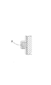
【図8】図8は図2におけるA−A線拡大一部省略断面図である。
【図9】図9は図2におけるB−B線拡大一部省略断面図である。
【図10】図10は図2におけるC−C線拡大断面図である。
【図11】図11は図2におけるD−D線拡大断面図である。
【図12】図12は他の実施例の発光素子の電極配置例を示す平面図である。
【図13】図13は同正面図である。
【図14】図14は同背面図である。
【図15】図15は同左側(右側)側面図である。
【図16】図16は同底面図である。
【図17】図17は透明な部分(透明電極)を示す参考平面図である。
【図18】図18は図12におけるA−A線拡大一部省略断面図である。
【図19】図19は図12におけるB−B線拡大一部省略断面図である。
【図20】図20は図12におけるC−C線拡大断面図である。
【図21】図21は他の実施例の発光素子の電極配置例を示す平面図である。
【図22】図22は同正面図である。
【図23】図23は同背面図である。
【図24】図24は同左側(右側)側面図である。
【図25】図25は同底面図である。
【図26】図26は透明な部分(透明電極)を示す参考平面図である。
【図27】図27は図21におけるA−A線拡大一部省略断面図である。
【図28】図28は図21におけるB−B線拡大一部省略断面図である。
【図29】図29は図21におけるC−C線拡大断面図である。
【図30】図30は図21におけるD−D線拡大断面図である。
【図31】図31は他の実施例の発光素子の電極配置例を示す平面図である。
【図32】図32は他の実施例の発光素子の電極配置例を示す平面図である。
【図33】図33は他の実施例の発光素子の電極配置例を示す平面図である。
【図34】図34は他の実施例の発光素子の電極配置例を示す平面図である。
【図35】図35は他の実施例の発光素子の電極配置例を示す平面図である。
【図36】図36は他の実施例の発光素子の電極配置例を示す平面図である。
【図37】図37は他の実施例の発光素子の電極配置例を示す平面図である。
【図38】図38は他の実施例の発光素子の電極配置例を示す平面図である。
【図39】図39は他の実施例の発光素子の電極配置例を示す平面図である。
【図40】図40は他の実施例の発光素子の電極配置例を示す平面図である。
【図41】図41は他の実施例の発光素子の電極配置例を示す平面図である。
【図42】図42は他の実施例の発光素子の電極配置例を示す平面図である。
【図43】図43は他の実施例の発光素子の電極配置例を示す平面図である。
【図44】図44は他の実施例の発光素子の電極配置例を示す平面図である。
【図45】図45は他の実施例の発光素子の電極配置例を示す平面図である。
【図46】図46は他の実施例の発光素子の電極配置例を示す平面図である。
【図47】図47は他の実施例の発光素子の電極配置例を示す平面図である。
【図48】図48は他の実施例の発光素子の電極配置例を示す平面図である。
【図49】図49は他の実施例の発光素子の電極配置例を示す平面図である。
【図50】図50は他の実施例の発光素子の電極配置例を示す平面図である。
【図51】図51は他の実施例の発光素子の電極配置例を示す平面図である。
【図52】図52は他の実施例の発光素子の電極配置例を示す平面図である。
【図53】図53は他の実施例の発光素子の電極配置例を示す平面図である。
【図54】図54は他の実施例の発光素子の電極配置例を示す平面図である。
【図55】図55は他の実施例の発光素子の電極配置例を示す平面図である。
【図56】図56は他の実施例の発光素子の電極配置例を示す平面図である。
【図57】図57は他の実施例の発光素子の電極配置例を示す平面図である。
【図58】図58は他の実施例の発光素子の電極配置例を示す平面図である。
【符号の説明】
10、23、33、43、43−1、53、63、303、303−1 発光素子
6、16,26、36、46、56、66、306 透光性電極
7 p電極
9 n電極
17、27、37、47、57、81、91、101、111、121、131、141、151、161、171、181、191、201、211、221、231、241、251 p台座電極
18、28、38、48、58、82、92、93、102、112、122、123、132、133、142、143、152、166、172、182、192 193、202、212、222、223、233、232、242、242 252 p補助電極
19、29、39、49、59、85、95、105、115、125、135、145、155、165、175、185、195、205、215、225、235、245、255 n台座電極
20、30、40、50、60、70、86、96、106、107、116、126 127、136、137、146、156、166、176、186、196 216、226、227、236、237、246、247、248、256、310、320 n補助電極[0001]
[Industrial application fields]
The present invention relates to a group III nitride compound semiconductor device. For example, it is a preferred invention as an improvement of an electrode of a group III nitride compound semiconductor light emitting device such as a blue light emitting diode.
[0002]
[Prior art]
In group III nitride compound semiconductor light emitting devices such as blue light emitting diodes, various proposals have been made in order to obtain uniform light emission from the entire surface of the device.
For example, in Japanese Patent Application Laid-Open Nos. 8-340131 and 10-1117017, p auxiliary electrodes are provided radially on the upper surface of the p contact layer to make the injection current density uniform for the p contact layer. For example, as disclosed in JP-A-10-275934, a translucent electrode is pasted on the upper surface of a p-type contact layer, and a p seat electrode is provided thereon. In this example, a p auxiliary electrode extends from the p seat electrode along the side of the element.
Examples in which an n auxiliary electrode is provided along an edge of an element from an n seat electrode formed at a corner of the element are disclosed in Japanese Patent Laid-Open Nos. 9-97922 and 2000-22210.
[0003]
[Problems to be solved by the invention]
According to the study by the present inventors, it has been found that it is desirable to increase the chip size of the light-emitting diodes to be used in a traffic light or the like that requires a high luminance and collects and uses light-emitting diodes of the same color. If the number of units used is reduced by increasing the chip size, the number of man-hours for assembling the light-emitting diodes will be reduced and the manufacturing cost will be reduced. In addition, the circuit design for evenly distributing the current to each light-emitting diode will be improved. It is easy and simple.
Therefore, the present inventors have repeatedly studied to increase the chip size of the light emitting diode. As a result, we came up with the next problem.
[0004]
Since the resistance of the n-contact layer (layer where the n-electrode is formed) in the light-emitting diode is relatively high, the current does not sufficiently reach a portion far from the n-electrode, and light emission at the portion decreases. On the other hand, strong light emission is obtained at a portion close to the n-electrode, so that the light emission is non-uniform when viewed from the entire device. From this point of view, when a conventional small element (300 to 400 μm □) is seen, it is somewhat dark at a portion far from the n-electrode, but since this portion is a very small region, the light emission is not uniform. Was not a major obstacle.
When the chip size is increased, the amount of current applied to the p seat electrode must be increased when an appropriate current density injected per unit light emitting area is to be ensured. The current applied to the p seat electrode flows from the p seat electrode into the translucent electrode. However, when the amount of current increases, seizure occurs between the p seat electrode and the translucent electrode (generated Joule heat). This increases the possibility that the translucent electrode of the joint portion will burn out). One factor that determines the amount of current that can be injected into the p seat electrode (allowable current amount) is the area of the interface between the p seat electrode and the translucent electrode, and the larger the area, the larger the allowable current amount. Conceivable.
Further, in a large chip having an outermost diameter of 700 μm or more, when trying to secure a current density suitable for an effective light emitting surface, a combination of one p seat electrode and one n seat electrode is caused by heat generated in the bonding wire portion. There is a risk that the mold resin may burn out or the bonding wire itself may break due to heat.
[0005]
[Means for Solving the Problems]
The present invention has been made to solve at least one of the above problems. That is, a group III nitride compound semiconductor device characterized in that, in an element having an outermost diameter of 700 μm or more, the distance from the n electrode to the point of the p electrode farthest is within 500 μm.
[0006]
According to the group III nitride compound semiconductor device configured as described above, since the point of the p-electrode farthest from the n-electrode is within the above distance, even if the resistance of the n-type semiconductor layer is high, Electrons are sufficiently injected into the part of the element farthest away (current is diffused). As a result, the entire surface of the device emits light more evenly.
Note that the relationship between the current density and the light emission output of the light emitting element is that the light emission output is saturated when the current density exceeds a predetermined value. That is, even if the current density exceeding the predetermined value is injected, the light emission output corresponding to the current density cannot be increased. Therefore, in order to achieve high light emission output and high light emission efficiency, it is preferable to achieve a current density in the vicinity of the predetermined value over the entire area of the device. If the distance between the n-electrode and the p-electrode is defined as in the present invention, the suitable current density can be obtained over the entire area of the element, and an element with excellent luminous efficiency can be provided.
[0007]
In this specification, the n electrode is composed of an n seat electrode and an n auxiliary electrode extending therefrom, and the p electrode is composed of a p seat electrode and a p auxiliary electrode extending from the p seat electrode. The outermost diameter of the element is the length of the longest straight line that can be drawn on the element when the element is viewed from a plane. When the element is rectangular, the length of the diagonal line is the outermost diameter. The same applies when the element is a diamond. When the element is circular or elliptical, it is a straight line passing through the center. Thus, the shape of the element is not particularly limited. In addition to the above, polygonal element shapes such as hexagons and octagons may be employed.
A more preferable upper limit of the distance between the n electrode and the p electrode farthest from the n electrode is 400 μm, and even more preferably 350 μm.
In the case of a rectangular chip, such a configuration is preferably applied to a chip having a side length of 500 μm or more (the outermost diameter is 700 μm or more). When the chip size is increased in this way, in a conventional n-electrode configuration, a portion that becomes dark without being able to obtain a sufficient current density at a distance from this becomes an unacceptably large region, and the region is There is a concern that the light emission mode may be unsuitable by appearing in the central portion of the element. More preferably, in the case of a rectangular chip, the length of one side is 600 μm or more, more preferably the length of one side is 700 μm or more, and most preferably 800 μm or more.
[0008]
Thus, in order to keep the distance between an arbitrary point of the p electrode and the n electrode within a predetermined range, in one aspect of the present invention, the n auxiliary electrode is extended from the n seat electrode to the central portion of the element. adopt.
Since the n auxiliary electrode exists in the central portion of the element, the distance from the n auxiliary electrode to all corners of the element is constant. Thereby, the fall of the light emission output in a corner | angular part can be prevented.
As described above, when the n-electrode was improved to ensure the uniform diffusion of current to the n-type semiconductor layer, the following problem emerged anew.
Even in the type in which a translucent electrode is pasted on a p-type semiconductor layer to diffuse current, when the chip size is increased and the distance from the p base electrode or the p auxiliary electrode is increased, the translucent electrode which is a thin film The resistance itself cannot be ignored, and the current cannot be sufficiently injected into the p-type semiconductor layer in a portion away from the p seat electrode or the p auxiliary electrode.
[0009]
Therefore, in one aspect of the present invention, the distance between an arbitrary point on the translucent electrode and the p seat electrode or the p auxiliary electrode is set within a range of 0 to 1000 μm.
According to the group III nitride compound semiconductor device configured as described above, since all the points of the translucent electrode are within the above-mentioned distance from the p seat electrode or the p auxiliary electrode, from the p seat electrode or the p auxiliary electrode. The current is sufficiently diffused to the portion of the translucent electrode farthest away and is injected into the p-type semiconductor layer below it. As a result, the entire surface of the element emits light substantially uniformly. The upper limit of a further preferable distance between an arbitrary point on the translucent electrode and the p seat electrode or the p auxiliary electrode is 500 μm, still more preferably 450 μm, still more preferably 400 μm, and most preferably 350 μm. It is.
In the case of a rectangular chip, such a configuration is preferably applied to a chip having a side length of 500 μm or more (the outermost diameter is 700 μm or more). When the chip size is increased in this way, in a conventional p-electrode configuration, a portion that becomes darker than a distance away from the current cannot be obtained, and a portion that becomes dark cannot be ignored. May appear in the center of the light and make the light emission mode unsuitable. More preferably, in the case of a rectangular chip, the length of one side is 600 μm or more, more preferably the length of one side is 700 μm or more, and most preferably 800 μm or more.
[0010]
Thus, in order to keep the distance between an arbitrary point on the translucent electrode and the p seat electrode or the p auxiliary electrode within a predetermined range, in one aspect of the present invention, the p auxiliary electrode is translucent from the p seat electrode. The structure which extends to the central part of the conductive electrode is adopted.
Since the p auxiliary electrode exists in the central portion of the translucent electrode, the distance to the corners of the p auxiliary electrode and the translucent electrode is constant. Thereby, the fall of the light emission output in a corner | angular part can be prevented.
[0011]
In the group III nitride compound semiconductor device having both the n electrode and the p electrode having the above-described configuration, it is preferable that the n auxiliary electrode and the p auxiliary electrode are arranged in a comb shape when the device is viewed from a plane. Since the element does not operate in the portion having the n auxiliary electrode and the p auxiliary electrode (the light emitting element does not emit light), the non-operating portion can be arranged in a symmetric or regular pattern in the element by arranging them in a comb shape. Become. Therefore, utilization of an element becomes easy. In the case of a light emitting element, it becomes easy to take out light uniformly outside.
[0012]
The group III nitride compound semiconductor device having both the n electrode and the p electrode configured as described above includes a portion in which the n auxiliary electrode and the p auxiliary electrode are arranged in parallel to each other when the device is viewed from a plane. Is preferred. Since the element does not operate in the portion having the n auxiliary electrode and the p auxiliary electrode (the light emitting element does not emit light), the non-operating portion can be arranged in a symmetric or regular pattern in the element by arranging the parallel portions. . Therefore, utilization of an element becomes easy. In the case of a light emitting element, it becomes easy to take out light uniformly outside.
[0013]
As the chip size increases, the power consumed by the element increases, so that the current applied to the pedestal electrode increases. When there is one pedestal electrode for each of the p side and the n side as in the prior art, there may be a problem that the mold resin is burned due to heat generated in the bonding wire portion or the bonding wire itself is disconnected by heat. Therefore, in another aspect of the present invention, a plurality of p seat electrodes and n seat electrodes are provided. Thereby, the above problem is solved.
A chip size in which a plurality of p seat electrodes and n seat electrodes are preferably provided is one having a side length of 500 μm or more (the outermost diameter is 700 μm or more) in the case of a rectangular chip. More preferably, the length of one side is 600 μm or more, still more preferably the length of one side is 700 μm or more, and most preferably 800 μm or more.
[0014]
When the chip size of the light emitting element is increased and the power consumption is increased, in addition to the above problems, there is a problem of seizure between the p seat electrode and the translucent electrode. Therefore, it is preferable to use the p auxiliary electrode from the p seat electrode. By providing the p auxiliary electrode, a sufficient area can be obtained between the p seat electrode and the p auxiliary electrode and the translucent electrode, thereby preventing the occurrence of seizure. As a result, the amount of current that can be applied to the p seat electrode (allowable current amount) is increased, and a sufficient amount of current can be secured for causing the entire surface of the device to emit light.
[0015]
Hereinafter, each of the elements constituting the present invention will be described in detail by taking a group III nitride compound semiconductor light emitting device as an example.
The n electrode is formed on the n contact layer exposed by etching the semiconductor layer. Any material can be selected as long as an ohmic contact with the n-type group III nitride compound semiconductor can be obtained, but an aluminum alloy such as a vanadium-aluminum alloy is preferably employed.
The shape of the n-electrode is also arbitrary, but according to one aspect of the present invention, in order to keep the distance from an arbitrary point of the p-electrode to the n-electrode within a certain range, the n-pedestal electrode and the electrode are extended from this. A combination with n auxiliary electrodes is also preferred. The n seat electrode may be disposed at substantially the center of one side of the element or may be disposed at the corner of the element. The n auxiliary electrode preferably has a portion extending from the n seat electrode to the central portion of the element.
[0016]
The n auxiliary electrode is preferably formed from the same material and the same method (the same mask) as the n seat electrode from the viewpoint of reducing the number of steps. In this case, the n auxiliary electrode and the n seat electrode have the same thickness.
The n auxiliary electrode and the n pedestal electrode may be formed separately. In this case, the material and thickness of the n auxiliary electrode can be different from those of the n seat electrode.
The shape of the n seat electrode is not particularly limited as long as it has a sufficient area for bonding a conductive wire by a known method.
Since the n auxiliary electrode is formed in a portion where the semiconductor layer is removed, it is preferable to narrow the width from the viewpoint of maximizing the area of the effective semiconductor layer. The width of the n auxiliary electrode is preferably 1 to 40 μm. More preferably, it is 2-30 micrometers, More preferably, it is 3-25 micrometers, Still more preferably, it is 3-20 micrometers, Most preferably, it is 5-15 micrometers.
[0017]
The material for forming the translucent electrode is not particularly limited. For example, a Co layer as the first electrode layer and an Au layer as the second electrode layer are sequentially stacked from the lower side.
The constituent element of the first electrode layer is an element having a lower ionization potential than the constituent element of the second electrode layer, and the constituent element of the second electrode layer is an element whose ohmic property to the semiconductor is better than the constituent element of the first electrode layer Is desirable. In order to form an alloy with the p-type contact layer, this electrode layer is also subjected to heat treatment. By this heat treatment, the element distribution in the depth direction from the surface of the semiconductor is the element of the second electrode layer. The distribution is deeper than the constituent elements of the first electrode layer. That is, the element distribution of the electrode layer is reversed with respect to the distribution at the time of forming the electrode layer. After the formation of the electrode layer, the constituent element of the second electrode layer formed on the upper side is on the lower side, and the constituent element of the first electrode layer formed on the lower side is on the upper side.
Preferably, the constituent elements of the first electrode layer are nickel (Ni), cobalt (Co), iron (Fe), copper (Cu), chromium (Cr), tantalum (Ta), vanadium (V), manganese (Mn ), Aluminum (Al), and silver (Ag), and the film thickness is 0.5 to 15 nm. The constituent element of the second electrode layer is at least one element selected from palladium (Pd), gold (Au), iridium (Ir), and platinum (Pt), and the film thickness is 3.5 to 25 nm. Most preferably, the constituent element of the first electrode layer is Co, and the constituent element of the second electrode layer is Au. In this case, by heat treatment, the element distribution in the depth direction from the surface of the semiconductor becomes a distribution in which Au penetrates deeper than Co.
[0018]
The material for forming the p seat electrode is not particularly limited. For example, a V layer as a first metal layer, an Au layer as a second metal layer, and an Al layer as a third metal layer are sequentially laminated from the lower side. .
The first metal layer is an element having an ionization potential lower than that of the second metal layer so that the first metal layer can be firmly bonded to the underlying layer. The second metal layer is an element that has good bonding properties with Al or Au and does not react with the translucent electrode. The third metal layer is preferably an element that can be firmly bonded to the protective film.
Preferably, the constituent elements of the first metal layer are nickel (Ni), iron (Fe), copper (Cu), chromium (Cr), tantalum (Ta), vanadium (V), manganese (Mn), cobalt (Co ) At least one element, and its film thickness is 1 to 300 nm.
Desirably, the constituent element of the third metal layer is at least one element of aluminum (Al), nickel (Ni), and titanium (Ti), and the film thickness thereof is 1 to 30 nm.
Desirably, the constituent element of the second metal layer is gold (Au), and the thickness thereof is 0.3 to 3 μm.
[0019]
The p auxiliary electrode is preferably formed from the same material and the same method (same mask) as the p seat electrode from the viewpoint of reducing the number of man-hours. In this case, the p auxiliary electrode and the p seat electrode have the same thickness.
The p auxiliary electrode and the p seat electrode may be formed separately. In this case, the material and thickness of the p auxiliary electrode may be different from those of the p seat electrode.
The shape of the p seat electrode is not particularly limited as long as it has a sufficient area for bonding a conductive wire by a known method. In order to confirm the position at the time of bonding, it is preferable to adopt a shape different from that of the n seat electrode as the p seat electrode.
Since the p auxiliary electrode shields light, it is preferable to narrow its width. The width of the p auxiliary electrode is preferably 1 to 40 μm. More preferably, it is 2-30 micrometers, More preferably, it is 3-25 micrometers, Still more preferably, it is 3-20 micrometers, Most preferably, it is 5-15 micrometers.
It is preferable to provide unevenness around the p seat electrode and / or the p auxiliary electrode to increase the contact area with the translucent electrode.
The peripheral surface of the p seat electrode is preferably inclined. By forming the peripheral surface of the pedestal electrode into a taper shape, a protective film (SiO 2) formed on the surface of the pedestal electrode and the translucent electrode 2 It is possible to form a film or the like on the taper-like portion almost as designed.
[0020]
In order to keep the distance from an arbitrary point of the translucent electrode to the p seat electrode or the p auxiliary electrode within a certain range, a combination of the p seat electrode and the p auxiliary electrode extended therefrom is preferable. . The p seat electrode may be disposed at substantially the center of one side of the element or may be disposed at the corner of the element.
The p auxiliary electrode is preferably formed in a comb shape with respect to the n auxiliary electrode. Here, the comb shape refers to a state in which p auxiliary electrodes and n auxiliary electrodes are alternately arranged when the element is viewed from a plane.
The p auxiliary electrode preferably includes a portion arranged in parallel to the n auxiliary electrode.
[0021]
The heat treatment for alloying the translucent electrode, the p seat electrode, and the p auxiliary electrode is preferably performed in a gas containing oxygen. At this time, as the gas containing oxygen, O 2 , O Three , CO, CO 2 , NO, N 2 O, NO 2 Or H 2 At least one kind of O or a mixed gas thereof can be used. Or O 2 , O Three , CO, CO 2 , NO, N 2 O, NO 2 Or H 2 A mixed gas of at least one of O and an inert gas, or O 2 , O Three , CO, CO 2 , NO, N 2 O, NO 2 Or H 2 A mixed gas of a mixed gas of O and an inert gas can be used. In short, a gas containing oxygen means an oxygen atom or a molecular gas having an oxygen atom.
The pressure of the atmosphere at the time of the heat treatment may be higher than the pressure at which the gallium nitride compound semiconductor is not thermally decomposed at the heat treatment temperature. Gas containing oxygen is O 2 When only gas is used, it may be introduced at a pressure higher than the decomposition pressure of the gallium nitride compound semiconductor. When used in a state mixed with other inert gas, all the gas is gallium nitride compound semiconductor. Pressure equal to or higher than the decomposition pressure of 2 The gas is 10% of the total gas -6 It is sufficient to have a proportion of more than about. In short, it is sufficient that a very small amount of oxygen-containing gas exists. Note that the upper limit of the amount of oxygen-containing gas introduced is not particularly limited from the characteristics of p-type resistance reduction and electrode alloying. In short, it can be used to the extent that it can be manufactured.
Regarding heat treatment, it is most desirably 500 to 600 ° C. A low-resistance p-type gallium nitride compound semiconductor whose resistivity is completely saturated at a temperature of 500 ° C. or higher can be obtained. Moreover, the alloying process of an electrode can be performed favorably at a temperature of 600 ° C. or lower. A desirable temperature range is 450 to 650 ° C.
For the formation material and heat treatment conditions of the p seat electrode, the p auxiliary electrode, and the translucent electrode, refer to JP-A-9-320984 and JP-A-10-209493.
[0022]
In this specification, a group III nitride compound semiconductor is expressed by a general formula of Al. X Ga Y In 1-XY N (0 ≦ X ≦ 1, 0 ≦ Y ≦ 1, 0 ≦ X + Y ≦ 1), a so-called binary system of AlN, GaN and InN, Al x Ga 1-x N, Al x In 1-x N and Ga x In 1-x It includes a so-called ternary system of N (where 0 <x <1). Part of group III elements may be substituted with boron (B), thallium (Tl), etc., and part of nitrogen (N) may also be phosphorus (P), arsenic (As), antimony (Sb), bismuth. It can be replaced with (Bi) or the like. The group III nitride compound semiconductor layer may contain an arbitrary dopant. Si, Ge, Se, Te, C, or the like can be used as the n-type impurity. Mg, Zn, Be, Ca, Sr, Ba, or the like can be used as the p-type impurity. It is also possible to expose the group III nitride compound semiconductor to electron beam irradiation, plasma irradiation or heating by a furnace after doping with a p-type impurity. The formation method of the group III nitride compound semiconductor layer is not particularly limited. In addition to the metal organic chemical vapor deposition method (MOCVD method), the known molecular beam crystal growth method (MBE method), halide vapor phase epitaxy method (HVPE method). ), A sputtering method, an ion plating method, an electron shower method, or the like.
Here, group III nitride compound semiconductor elements include light-emitting diodes, light-receiving diodes, laser diodes, optical elements such as solar cells, bipolar elements such as rectifiers, thyristors, and transistors, unipolar elements such as FETs, and microwave elements. And electronic devices. The present invention is also applicable to a laminate as an intermediate of these elements.
Note that the light-emitting element can have a homo structure, a hetero structure, or a double hetero structure having a MIS junction, a PIN junction, or a pn junction. Quantum well structure as light emitting layer (single quantum well structure or multiple quantum well structure)
Can also be adopted.
[0023]
【Example】
Examples of the present invention will be described below.
The embodiment is a light-emitting
[0024]
The n-type cladding layer 3 can have a two-layer structure including a low electron concentration n− layer on the light emitting layer 4 side and a high electron concentration n + layer on the buffer layer 2 side. The latter is called an n-type contact layer.
The light emitting layer 4 is not limited to a superlattice structure. As a structure of the light emitting element, a single hetero type, a double hetero type, a homojunction type, or the like can be used.
A group III nitride compound semiconductor layer having a wide band gap doped with an acceptor such as magnesium may be interposed between the light emitting layer 4 and the p-type cladding layer 5. This is to prevent electrons injected into the light emitting layer 4 from diffusing into the p-type cladding layer 5.
The p-type cladding layer 5 can have a two-layer structure including a low hole concentration p− layer on the light emitting layer 4 side and a high hole concentration p + layer on the electrode side. The latter is called a p-type contact layer.
In the light emitting diode having the above structure, each group III nitride compound semiconductor layer is formed by executing MOCVD under general conditions.
[0026]
Next, a mask is formed and a part of the p-type cladding layer 5, the active layer 4 and the n-type cladding layer 3 is removed by reactive ion etching, and an n-electrode forming surface 11 on which the n-
[0027]
A Co layer (1.5 nm) and an Au layer (60 nm) are sequentially stacked on the entire surface of the wafer by a vapor deposition apparatus. Next, a photoresist is uniformly applied, and the photoresist is removed from the n-electrode formation surface 11 and the periphery thereof by a portion (clearance region 13) having a width of about 10 μm by photolithography. The photoelectrode forming material is removed to expose the semiconductor layer. Thereafter, the photoresist is removed.
Next, a V layer (17.5 nm), an Au layer (1.5 μm), and an Al layer (10 nm) are sequentially deposited by a lift-off method to form a p seat electrode 7 and a p auxiliary electrode 7 (p electrode 7). .
Similarly, the n-
[0028]
The sample obtained as described above is put into a heating furnace, the inside of the furnace is evacuated to 1 Pa or less, and then O to 10 several Pa. 2 Supply. In this state, the furnace temperature is set to 550 ° C. and heat treatment is performed for about 4 minutes. As a result, the translucent electrode 6, the p seat electrode, and the p auxiliary electrode are alloyed with each other, and both are combined to form a p electrode.
According to the study by the present inventors, almost no current is injected into the p-type cladding layer immediately below the p seat electrode and the p auxiliary electrode. This is because the contact resistance is relatively high because the Au / Co vapor deposition layer constituting the translucent electrode does not invert the distribution as described above immediately below the p seat electrode and the p auxiliary electrode. It is expected to be. Therefore, the interface between the peripheral surfaces of the p seat electrode and the p auxiliary electrode and the translucent electrode 6 is an effective electrical connection surface between them. That is, the current applied to the p seat electrode flows from the peripheral surfaces of the p seat electrode and the p auxiliary electrode to the translucent electrode, where it is diffused over the entire surface and uniformly injected into the entire surface of the p-type semiconductor layer.
An insulating and translucent protective film 14 (silicon oxide, silicon nitride, titanium oxide, aluminum oxide, etc.) is provided over the entire surface other than the region where wire bonding or the like on the p seat electrode is applied and the upper surface of the n electrode and its peripheral portion. Covered. A sputtering method or a CVD method can be employed as a method for forming the protective film 14.
[0029]
An example of the electrode arrangement of the light-emitting
The
This element is a square having a side length of 1000 μm.
[0030]
Examples of electrode arrangement of other light emitting elements 23 are shown in FIGS. In FIG. 12,
The
This element is a square having a side length of 600 μm.
[0031]
Examples of electrode arrangement of other
The
This element is a square having a side length of 1000 μm.
[0032]
An example of electrode arrangement of another
The
This element is a square having a side length of 800 μm.
[0033]
FIG. 32 shows a modification of FIG. In the element 43-1 of FIG. 32, branches 50-2 and 50-3 are formed on the n auxiliary electrode 50-1. Each branch 50-2, 50-3 extends toward the
In FIG. 32, the same elements as those in FIG.
[0034]
An example of electrode arrangement of another
The
This element is a square having a side length of 800 μm.
[0035]
An example of electrode arrangement of another
The
This element is a square having a side length of 800 μm.
[0036]
Other electrode arrangement examples of the light-emitting element are shown in FIGS. In these examples, only the p electrode and the n electrode (shown by hatching) are shown for the sake of simplicity. Also in the examples of FIGS. 35 to 52, as described in the examples before FIG. 34, the translucent electrode is attached to almost the entire surface of the p-type semiconductor layer, and the p electrode is the same as the translucent electrode. It is formed above. Although the illustration of the n-electrode forming surface and the protective film is omitted, these are also formed in the same manner as in the previous example. Further, in the following description, for convenience of description, the positional relationship (up / down / left / right) of the elements is defined with reference to the drawings.
The length of one side of the light emitting elements in these examples is also 500 μm or more.
[0037]
In the example of FIG. 35,
[0038]
In the example of FIG. 36,
[0039]
In the example of FIG. 37,
[0040]
In the example of FIG. 38, the
[0041]
In the example of FIG. 39, the
[0042]
In the example of FIG. 40, the
[0043]
In the example of FIG. 41, the
[0044]
In the example of FIG. 42, the
[0045]
In the example of FIG. 43, the
[0046]
In the example of FIG. 44, the
[0047]
In the example of FIG. 45,
[0048]
In the example of FIG. 46,
[0049]
In the example of FIG. 47, the
[0050]
In the example of FIG. 48,
[0051]
In the example of FIG. 49, the
[0052]
In the example of FIG. 50, the
[0053]
In the example of FIG. 51, the element is rectangular in plan view. The
[0054]
In the example of FIG. 52, the
[0055]
An example of electrode arrangement of another
The
This element is a square having a side length of 1000 μm.
[0056]
FIG. 54 shows a modification of FIG. The element 303-1 in FIG. 54 employs a C-shaped n
In FIG. 54, the same elements as those of FIG. 53 are denoted by the same reference numerals, and the description thereof is omitted.
[0057]
An example of electrode arrangement of another
This element is a square having a side length of 1000 μm.
[0058]
An example of electrode arrangement of another
This element is a square having a side length of 1000 μm.
[0059]
An example of electrode arrangement of another
The
[0060]
An example of electrode arrangement of another
[0061]
The present invention is not limited to the description of the embodiments and examples of the invention described above. Various modifications may be included in the present invention as long as those skilled in the art can easily conceive without departing from the description of the scope of claims.
[0062]
The following matters are disclosed below.
11 A group III nitride compound semiconductor device, wherein an n auxiliary electrode extends from an n seat electrode to a central portion of the device when the device is viewed from a plane.
12. The group III nitride compound semiconductor device according to 11, wherein the device has a rectangular shape when viewed from a plane, and the length of one side is 500 μm or more.
[13] The group III nitride system according to [11] or [12], wherein the element has a translucent electrode, a p electrode comprising a p seat electrode and a p auxiliary electrode extended from the p seat electrode Compound semiconductor device.
14. The group III nitride compound semiconductor device according to 13, wherein a distance between an arbitrary point of the translucent electrode and the p seat electrode or the p auxiliary electrode is in a range of 0 to 1000 μm.
[15] The group III nitride compound semiconductor according to [13] or [14], wherein the n auxiliary electrode and the p auxiliary electrode are arranged in a comb shape.
16 The group III nitride compound semiconductor device according to any one of 13 to 15, wherein the n auxiliary electrode and the p auxiliary electrode include portions arranged in parallel to each other.
17 A group III nitride compound semiconductor device according to any one of 13 to 16, wherein a plurality of the n seat electrodes are disposed and a plurality of the p seat electrodes are disposed.
[18] The group III nitride compound semiconductor device according to any one of [11] to [17], which has a light emitting device structure or a light receiving device structure.
21 A group III nitride compound semiconductor device, wherein a distance between an arbitrary point of the translucent electrode and the p seat electrode or the p auxiliary electrode is in a range of 0 to 1000 μm.
22. The group III nitride compound semiconductor device according to 21, wherein the device has a rectangular shape when viewed from a plane, and a length of one side is 500 μm or more.
23. The group III nitride compound semiconductor according to any one of 21 and 22, wherein the n auxiliary electrode and the p auxiliary electrode are arranged in a comb shape.
24. The group III nitride compound semiconductor device according to any one of 21 to 23, wherein the n auxiliary electrode and the p auxiliary electrode include portions arranged in parallel to each other.
25 The group III nitride compound semiconductor device according to any one of 21 to 24, wherein a plurality of the n seat electrodes are disposed and a plurality of the p seat electrodes are disposed.
26 The group III nitride compound semiconductor device according to any one of 21 to 25, which has a light emitting device structure or a light receiving device structure.
31 n electrode having n pedestal electrode and n auxiliary electrode;
A translucent electrode;
a p electrode having a p seat electrode and a p auxiliary electrode,
A group III nitride compound semiconductor, wherein the n auxiliary electrode and the p auxiliary electrode are arranged in a comb shape when the device is viewed from a plane.
32. The group III nitride compound semiconductor device according to 31, wherein the device has a rectangular shape when viewed from a plane, and a length of one side is 500 μm or more.
33. The group III nitride compound semiconductor device according to 31 or 32, wherein a plurality of the n seat electrodes are disposed and a plurality of the p seat electrodes are disposed.
34. A Group III nitride compound semiconductor device according to any one of 31 to 33, which has a light emitting device structure or a light receiving device structure.
41 n electrode having n pedestal electrode and n auxiliary electrode;
A translucent electrode;
a p electrode having a p seat electrode and a p auxiliary electrode,
The group III nitride compound semiconductor, wherein the n auxiliary electrode and the p auxiliary electrode include portions arranged in parallel to each other when the device is viewed from a plane.
42. The group III nitride compound semiconductor device according to 41, wherein the device has a rectangular shape when viewed from a plane, and a length of one side is 500 μm or more.
43 The group III nitride compound semiconductor device according to 41 or 42, wherein a plurality of the n seat electrodes are disposed and a plurality of the p seat electrodes are disposed.
44. The group III nitride compound semiconductor device according to any one of 41 to 43, which has a light emitting device structure or a light receiving device structure.
51 A group III nitride compound semiconductor, wherein the element is rectangular when viewed from above and has a side length of 500 μm or more, and includes a plurality of n seat electrodes and a plurality of p seat electrodes. element.
52. Two n seat electrodes are disposed on the first side, two p seat electrodes are disposed on the second side facing the first side, and n auxiliary electrodes are extended from the n seat electrode. 53. The group III nitride compound semiconductor device according to 51, wherein a p auxiliary electrode extends from the p seat electrode.
53. A group III nitride compound semiconductor device according to 51 or 52, which has a light emitting device structure or a light receiving device structure.
[Brief description of the drawings]
FIG. 1 illustrates a layer structure of a light emitting device according to an embodiment of the present invention.
FIG. 2 is a plan view showing an example of electrode arrangement of the light emitting device of the example.
FIG. 3 is a front view of the same.
FIG. 4 is a rear view of the same.
FIG. 5 is a left (right) side view of the same.
FIG. 6 is a bottom view of the same.
FIG. 7 is a reference plan view showing a transparent portion (transparent electrode).
8 is a partially enlarged cross-sectional view taken along line AA in FIG. 2. FIG.
9 is a partially omitted cross-sectional view taken along line BB in FIG. 2. FIG.
FIG. 10 is an enlarged cross-sectional view taken along the line CC in FIG.
11 is an enlarged sectional view taken along line DD in FIG. 2. FIG.
FIG. 12 is a plan view showing an electrode arrangement example of a light emitting device according to another embodiment.
FIG. 13 is a front view of the same.
FIG. 14 is a rear view of the same.
FIG. 15 is a left (right) side view of the same.
FIG. 16 is a bottom view of the same.
FIG. 17 is a reference plan view showing a transparent portion (transparent electrode).
18 is a partially omitted cross-sectional view taken along line AA in FIG.
19 is a partially enlarged cross-sectional view taken along line BB in FIG.
FIG. 20 is an enlarged cross-sectional view taken along the line CC in FIG.
FIG. 21 is a plan view showing an electrode arrangement example of a light emitting device according to another embodiment.
FIG. 22 is a front view of the same.
FIG. 23 is a rear view of the same.
FIG. 24 is a left (right) side view of the same.
FIG. 25 is a bottom view of the same.
FIG. 26 is a reference plan view showing a transparent portion (transparent electrode).
27 is a partially omitted cross-sectional view taken along line AA in FIG. 21. FIG.
28 is a partially enlarged cross-sectional view taken along line BB in FIG. 21. FIG.
29 is an enlarged sectional view taken along line CC in FIG. 21. FIG.
30 is an enlarged sectional view taken along line DD in FIG. 21. FIG.
FIG. 31 is a plan view showing an electrode arrangement example of a light emitting device according to another embodiment.
FIG. 32 is a plan view showing an electrode arrangement example of a light emitting device of another embodiment.
FIG. 33 is a plan view showing an electrode arrangement example of a light emitting device according to another embodiment.
FIG. 34 is a plan view showing an example of electrode arrangement of a light emitting device according to another embodiment.
FIG. 35 is a plan view showing an electrode arrangement example of a light emitting device of another embodiment.
FIG. 36 is a plan view showing an example of electrode arrangement of a light emitting device according to another embodiment.
FIG. 37 is a plan view showing an electrode arrangement example of a light emitting device of another embodiment.
FIG. 38 is a plan view showing an electrode arrangement example of a light emitting device according to another embodiment.
FIG. 39 is a plan view showing an example of electrode arrangement of a light emitting device according to another embodiment.
FIG. 40 is a plan view showing an example of electrode arrangement of a light emitting device of another example.
FIG. 41 is a plan view showing an electrode arrangement example of a light emitting device of another example.
FIG. 42 is a plan view showing an electrode arrangement example of a light emitting device according to another embodiment.
FIG. 43 is a plan view showing an electrode arrangement example of a light emitting device of another embodiment.
FIG. 44 is a plan view showing an electrode arrangement example of a light emitting device of another example.
FIG. 45 is a plan view showing an electrode arrangement example of a light emitting device of another embodiment.
FIG. 46 is a plan view showing an example of electrode arrangement of a light emitting device of another example.
FIG. 47 is a plan view showing an electrode arrangement example of a light emitting device of another example.
FIG. 48 is a plan view showing an electrode arrangement example of a light emitting device of another embodiment.
FIG. 49 is a plan view showing an electrode arrangement example of a light emitting device of another embodiment.
FIG. 50 is a plan view showing an electrode arrangement example of a light emitting device according to another embodiment.
FIG. 51 is a plan view showing an electrode arrangement example of a light emitting device of another example.
FIG. 52 is a plan view showing an electrode arrangement example of a light emitting device of another example.
FIG. 53 is a plan view showing an electrode arrangement example of a light emitting device of another embodiment.
FIG. 54 is a plan view showing an electrode arrangement example of a light emitting device of another embodiment.
FIG. 55 is a plan view showing an electrode arrangement example of a light emitting device of another embodiment.
FIG. 56 is a plan view showing an electrode arrangement example of a light emitting device of another example.
FIG. 57 is a plan view showing an electrode arrangement example of a light emitting device of another example.
FIG. 58 is a plan view showing an electrode arrangement example of a light emitting device of another example.
[Explanation of symbols]
10, 23, 33, 43, 43-1, 53, 63, 303, 303-1 Light emitting element
6, 16, 26, 36, 46, 56, 66, 306 Translucent electrode
7 p electrode
9 n electrode
17, 27, 37, 47, 57, 81, 91, 101, 111, 121, 131, 141, 151, 161, 171, 181, 191, 2011, 211, 221, 231, 241, 251 p pedestal electrode
18, 28, 38, 48, 58, 82, 92, 93, 102, 112, 122, 123, 132, 133, 142, 143, 152, 166, 172, 182, 192 193, 202, 212, 222, 223 233, 232, 242, 242 252 p auxiliary electrode
19, 29, 39, 49, 59, 85, 95, 105, 115, 125, 135, 145, 155, 165, 175, 185, 195, 205, 215, 225, 235, 245, 255 n seat electrode
20, 30, 40, 50, 60, 70, 86, 96, 106, 107, 116, 126 127, 136, 137, 146, 156, 166, 176, 186, 196 216, 226, 227, 236, 237, 246, 247, 248, 256, 310, 320 n auxiliary electrode
Claims (4)
前記p型層の上面に形成された透光性電極と、
前記透光性電極の上面に形成された、ワイヤをボンディングするためのp台座電極、及び、該p台座電極から延長されたp補助電極を有するp電極と、
前記n電極形成面に形成されたワイヤをボンディングするためのn台座電極、及び、該n台座電極から延長されたn補助電極を有するn電極と
を備え、
前記p台座電極が独立して複数設けられ、
前記透光性電極上の任意の点と前記p台座電極又は前記p補助電極との距離の上限は350μmである、ことを特徴とするIII族窒化物系化合物半導体素子。The element is rectangular when viewed from the plane, and an n-type layer, a light-emitting layer, and a p-type layer are formed in this order, and a part of the p-type layer, the light-emitting layer, and the n-type layer is removed to form an n-electrode formation surface. In the exposed group III nitride compound semiconductor device,
A translucent electrode formed on the upper surface of the p-type layer;
A p-electrode formed on the translucent electrode for bonding a wire, and a p-electrode having a p-auxiliary electrode extended from the p-base electrode;
An n seat electrode for bonding the wire formed on the n electrode forming surface, and an n electrode having an n auxiliary electrode extended from the n seat electrode,
A plurality of the p seat electrodes are provided independently;
A group III nitride compound semiconductor device, wherein an upper limit of a distance between an arbitrary point on the translucent electrode and the p seat electrode or the p auxiliary electrode is 350 μm.
Priority Applications (1)
| Application Number | Priority Date | Filing Date | Title |
|---|---|---|---|
| JP2001101990A JP4810746B2 (en) | 2000-03-31 | 2001-03-30 | Group III nitride compound semiconductor device |
Applications Claiming Priority (4)
| Application Number | Priority Date | Filing Date | Title |
|---|---|---|---|
| JP2000-96865 | 2000-03-31 | ||
| JP2000096865 | 2000-03-31 | ||
| JP2000096865 | 2000-03-31 | ||
| JP2001101990A JP4810746B2 (en) | 2000-03-31 | 2001-03-30 | Group III nitride compound semiconductor device |
Publications (3)
| Publication Number | Publication Date |
|---|---|
| JP2001345480A JP2001345480A (en) | 2001-12-14 |
| JP2001345480A5 JP2001345480A5 (en) | 2008-04-17 |
| JP4810746B2 true JP4810746B2 (en) | 2011-11-09 |
Family
ID=26589066
Family Applications (1)
| Application Number | Title | Priority Date | Filing Date |
|---|---|---|---|
| JP2001101990A Expired - Fee Related JP4810746B2 (en) | 2000-03-31 | 2001-03-30 | Group III nitride compound semiconductor device |
Country Status (1)
| Country | Link |
|---|---|
| JP (1) | JP4810746B2 (en) |
Families Citing this family (88)
| Publication number | Priority date | Publication date | Assignee | Title |
|---|---|---|---|---|
| US6825501B2 (en) * | 1997-08-29 | 2004-11-30 | Cree, Inc. | Robust Group III light emitting diode for high reliability in standard packaging applications |
| CN100461467C (en) * | 2002-10-03 | 2009-02-11 | 日亚化学工业株式会社 | Light emitting diode |
| JP4635985B2 (en) * | 2002-10-03 | 2011-02-23 | 日亜化学工業株式会社 | Light emitting diode |
| JP3956918B2 (en) | 2002-10-03 | 2007-08-08 | 日亜化学工業株式会社 | Light emitting diode |
| JP2004363572A (en) * | 2003-05-12 | 2004-12-24 | Showa Denko Kk | Semiconductor light emitting device and light emitting diode |
| US6869812B1 (en) | 2003-05-13 | 2005-03-22 | Heng Liu | High power AllnGaN based multi-chip light emitting diode |
| JP4572604B2 (en) * | 2003-06-30 | 2010-11-04 | 日亜化学工業株式会社 | Semiconductor light emitting element and light emitting device using the same |
| JP4581540B2 (en) * | 2003-06-30 | 2010-11-17 | 日亜化学工業株式会社 | Semiconductor light emitting element and light emitting device using the same |
| JP4438492B2 (en) * | 2003-09-11 | 2010-03-24 | 日亜化学工業株式会社 | Semiconductor device and manufacturing method thereof |
| US7915085B2 (en) | 2003-09-18 | 2011-03-29 | Cree, Inc. | Molded chip fabrication method |
| DE102004025610A1 (en) * | 2004-04-30 | 2005-11-17 | Osram Opto Semiconductors Gmbh | Optoelectronic component with several current spreading layers and method for its production |
| JP4632690B2 (en) * | 2004-05-11 | 2011-02-16 | スタンレー電気株式会社 | Semiconductor light emitting device and manufacturing method thereof |
| WO2005122288A1 (en) * | 2004-06-09 | 2005-12-22 | Showa Denko K.K. | Trnsparent positive electrode for gallium nitride-based compound semiconductor light-emitting device and light-emitting device |
| WO2006028118A1 (en) * | 2004-09-08 | 2006-03-16 | Rohm Co., Ltd | Semiconductor light-emitting device |
| TWI291243B (en) * | 2005-06-24 | 2007-12-11 | Epistar Corp | A semiconductor light-emitting device |
| WO2007010793A1 (en) * | 2005-07-15 | 2007-01-25 | Matsushita Electric Industrial Co., Ltd. | Semiconductor light-emitting device and board mounted with semiconductor light emitting device |
| KR100616693B1 (en) | 2005-08-09 | 2006-08-28 | 삼성전기주식회사 | Semiconductor light emitting device |
| KR100661614B1 (en) | 2005-10-07 | 2006-12-26 | 삼성전기주식회사 | Nitride semiconductor light emitting device and method of manufacturing the same |
| KR100730082B1 (en) | 2005-10-17 | 2007-06-19 | 삼성전기주식회사 | Nitride semiconductor light emitting device |
| KR100706944B1 (en) | 2005-10-17 | 2007-04-12 | 삼성전기주식회사 | Nitride semiconductor light emitting device |
| JP2007123517A (en) * | 2005-10-27 | 2007-05-17 | Toshiba Corp | Semiconductor light-emitting element, and semiconductor light-emitting apparatus |
| KR100833309B1 (en) * | 2006-04-04 | 2008-05-28 | 삼성전기주식회사 | Nitride semiconductor light emitting device |
| JP5056082B2 (en) | 2006-04-17 | 2012-10-24 | 日亜化学工業株式会社 | Semiconductor light emitting device |
| JP4823866B2 (en) * | 2006-11-13 | 2011-11-24 | 株式会社小糸製作所 | Light emitting module for vehicular lamp |
| KR100814464B1 (en) | 2006-11-24 | 2008-03-17 | 삼성전기주식회사 | Nitride semiconductor light emitting device |
| JP5023691B2 (en) * | 2006-12-26 | 2012-09-12 | 日亜化学工業株式会社 | Semiconductor light emitting device |
| US9024349B2 (en) | 2007-01-22 | 2015-05-05 | Cree, Inc. | Wafer level phosphor coating method and devices fabricated utilizing method |
| US9159888B2 (en) | 2007-01-22 | 2015-10-13 | Cree, Inc. | Wafer level phosphor coating method and devices fabricated utilizing method |
| JP5141086B2 (en) * | 2007-04-25 | 2013-02-13 | 日亜化学工業株式会社 | Semiconductor light emitting device |
| KR101354981B1 (en) | 2007-11-14 | 2014-01-27 | 삼성전자주식회사 | Nitride based Light Emitting Diode |
| US9041285B2 (en) | 2007-12-14 | 2015-05-26 | Cree, Inc. | Phosphor distribution in LED lamps using centrifugal force |
| US8878219B2 (en) | 2008-01-11 | 2014-11-04 | Cree, Inc. | Flip-chip phosphor coating method and devices fabricated utilizing method |
| US8115222B2 (en) | 2008-01-16 | 2012-02-14 | Rohm Co., Ltd. | Semiconductor light emitting device and fabrication method for the semiconductor light emitting device |
| CN101499510B (en) * | 2008-01-30 | 2011-06-22 | 富士迈半导体精密工业(上海)有限公司 | Semiconductor luminous element |
| KR100988041B1 (en) | 2008-05-15 | 2010-10-18 | 주식회사 에피밸리 | Semiconductor light emitting device |
| KR101000277B1 (en) | 2008-12-04 | 2010-12-10 | 주식회사 에피밸리 | Semiconductor light emitting device |
| JP5614938B2 (en) * | 2009-02-26 | 2014-10-29 | 日亜化学工業株式会社 | Semiconductor light emitting device |
| JP2010225771A (en) | 2009-03-23 | 2010-10-07 | Toyoda Gosei Co Ltd | Semiconductor light emitting element |
| KR101021974B1 (en) | 2009-04-08 | 2011-03-16 | (주)더리즈 | Semiconductor device chip for self-assembly package |
| JP5392611B2 (en) * | 2009-09-14 | 2014-01-22 | スタンレー電気株式会社 | Semiconductor light emitting device and method for manufacturing semiconductor light emitting device |
| US9324691B2 (en) | 2009-10-20 | 2016-04-26 | Epistar Corporation | Optoelectronic device |
| JP5560674B2 (en) * | 2009-11-27 | 2014-07-30 | 日亜化学工業株式会社 | Semiconductor light emitting device |
| JP2011119519A (en) * | 2009-12-04 | 2011-06-16 | Showa Denko Kk | Semiconductor light emitting element and semiconductor light emitting device |
| US9236532B2 (en) | 2009-12-14 | 2016-01-12 | Seoul Viosys Co., Ltd. | Light emitting diode having electrode pads |
| KR101055768B1 (en) * | 2009-12-14 | 2011-08-11 | 서울옵토디바이스주식회사 | Light Emitting Diodes with Electrode Pads |
| JP5443286B2 (en) * | 2009-12-24 | 2014-03-19 | スタンレー電気株式会社 | Face-up type optical semiconductor device |
| KR101625125B1 (en) * | 2009-12-29 | 2016-05-27 | 서울바이오시스 주식회사 | Light emitting diode having electrode extensions |
| WO2011083923A2 (en) * | 2010-01-07 | 2011-07-14 | Seoul Opto Device Co., Ltd. | Light emitting diode having electrode pads |
| KR101625122B1 (en) * | 2010-01-18 | 2016-05-27 | 서울바이오시스 주식회사 | Light emitting diode having electrode pads |
| KR101636034B1 (en) * | 2010-02-12 | 2016-07-05 | 서울바이오시스 주식회사 | Light emitting diode having electrode pads |
| JP5494005B2 (en) | 2010-02-26 | 2014-05-14 | 豊田合成株式会社 | Semiconductor light emitting device |
| JP5087097B2 (en) | 2010-03-08 | 2012-11-28 | 株式会社東芝 | Semiconductor light emitting device |
| KR101021988B1 (en) * | 2010-06-24 | 2011-03-16 | (주)더리즈 | Semiconductor light emitting device |
| TWI446527B (en) * | 2010-07-02 | 2014-07-21 | Epistar Corp | An optoelectronic device |
| JP2012028749A (en) * | 2010-07-22 | 2012-02-09 | Seoul Opto Devices Co Ltd | Light-emitting diode |
| US10546846B2 (en) | 2010-07-23 | 2020-01-28 | Cree, Inc. | Light transmission control for masking appearance of solid state light sources |
| BR112013001623B1 (en) | 2010-07-23 | 2021-02-02 | Nichia Corporation | light emitting element |
| JP2012054525A (en) | 2010-08-04 | 2012-03-15 | Toshiba Corp | Semiconductor light-emitting device |
| JP5095785B2 (en) | 2010-08-09 | 2012-12-12 | 株式会社東芝 | Semiconductor light emitting device and manufacturing method thereof |
| US20120037946A1 (en) * | 2010-08-12 | 2012-02-16 | Chi Mei Lighting Technology Corporation | Light emitting devices |
| JP5737066B2 (en) | 2010-08-26 | 2015-06-17 | 日亜化学工業株式会社 | Semiconductor light emitting device |
| WO2012057469A2 (en) * | 2010-10-25 | 2012-05-03 | 주식회사 세미콘라이트 | Semiconductor light-emitting device |
| KR101087970B1 (en) | 2010-10-25 | 2011-12-01 | 주식회사 세미콘라이트 | Semiconductor light emitting device |
| JP5605189B2 (en) * | 2010-11-26 | 2014-10-15 | 豊田合成株式会社 | Semiconductor light emitting device |
| JP5652234B2 (en) | 2011-02-07 | 2015-01-14 | 日亜化学工業株式会社 | Semiconductor light emitting device |
| KR101786094B1 (en) * | 2011-06-23 | 2017-10-16 | 엘지이노텍 주식회사 | Light emitting device, light emitting device package, and light unit |
| JP4970611B2 (en) * | 2011-07-29 | 2012-07-11 | 株式会社東芝 | Semiconductor light emitting device |
| WO2013024921A1 (en) * | 2011-08-17 | 2013-02-21 | 삼성전자주식회사 | Semiconductor light emitting device |
| JP5766095B2 (en) * | 2011-11-07 | 2015-08-19 | シチズンホールディングス株式会社 | Semiconductor light emitting device |
| KR101901589B1 (en) * | 2011-11-14 | 2018-09-27 | 엘지이노텍 주식회사 | Light emitting device |
| KR101954204B1 (en) * | 2012-08-28 | 2019-06-12 | 엘지이노텍 주식회사 | Light emitting device |
| KR101973765B1 (en) * | 2012-09-14 | 2019-04-30 | 포항공과대학교 산학협력단 | Semiconductor light emitting device with improved emitting efficiency |
| JP6102677B2 (en) * | 2012-12-28 | 2017-03-29 | 日亜化学工業株式会社 | Light emitting element |
| KR101986720B1 (en) * | 2013-01-03 | 2019-06-10 | 엘지이노텍 주식회사 | Light emitting device |
| JP6331906B2 (en) * | 2013-09-13 | 2018-05-30 | 日亜化学工業株式会社 | Light emitting element |
| JP2015109332A (en) * | 2013-12-04 | 2015-06-11 | シャープ株式会社 | Semiconductor light emitting element |
| JP6458463B2 (en) | 2013-12-09 | 2019-01-30 | 日亜化学工業株式会社 | Light emitting element |
| KR101625131B1 (en) | 2013-12-17 | 2016-05-27 | 서울바이오시스 주식회사 | Light emitting diode having electrode pads |
| US20150364651A1 (en) * | 2014-06-12 | 2015-12-17 | Toshiba Corporation | Flip-Chip Light Emitting Diode Assembly With Relief Channel |
| KR102407827B1 (en) * | 2015-01-27 | 2022-06-13 | 서울바이오시스 주식회사 | Light emitting device |
| KR102288376B1 (en) * | 2014-09-30 | 2021-08-11 | 서울바이오시스 주식회사 | Light emitting diode |
| KR101539430B1 (en) * | 2014-09-02 | 2015-07-27 | 서울바이오시스 주식회사 | Light emmiting diode and method for fabricating the same |
| EP3062354B1 (en) | 2015-02-26 | 2020-10-14 | Nichia Corporation | Light emitting element |
| JP6428467B2 (en) * | 2015-04-24 | 2018-11-28 | 日亜化学工業株式会社 | Light emitting element |
| KR101662198B1 (en) * | 2015-12-30 | 2016-10-05 | 서울바이오시스 주식회사 | Light emitting diode having electrode extensions |
| KR102059974B1 (en) * | 2019-04-26 | 2019-12-27 | 에피스타 코포레이션 | Optoelectronic device |
| KR102053426B1 (en) * | 2019-05-29 | 2019-12-06 | 엘지이노텍 주식회사 | Light emitting device and light emitting device package having the same |
| KR102544373B1 (en) * | 2020-12-22 | 2023-06-15 | 중앙대학교 산학협력단 | Light emitting diode comprising c2 symmetry |
Family Cites Families (8)
| Publication number | Priority date | Publication date | Assignee | Title |
|---|---|---|---|---|
| JPH0373185A (en) * | 1989-01-01 | 1991-03-28 | Hiromitsu Saito | Cutter guide |
| JP3234993B2 (en) * | 1992-09-24 | 2001-12-04 | ローム株式会社 | Light emitting diode chip and light emitting diode chip array using the same |
| DE19517697A1 (en) * | 1995-05-13 | 1996-11-14 | Telefunken Microelectron | Orange to green light emitting semiconductor LED |
| JP3960636B2 (en) * | 1995-09-29 | 2007-08-15 | 三洋電機株式会社 | Light emitting element |
| JPH10294493A (en) * | 1997-02-21 | 1998-11-04 | Toshiba Corp | Semiconductor light-emitting device |
| JP3369089B2 (en) * | 1997-11-13 | 2003-01-20 | 日亜化学工業株式会社 | Gallium nitride based compound semiconductor light emitting device |
| US6346771B1 (en) * | 1997-11-19 | 2002-02-12 | Unisplay S.A. | High power led lamp |
| US6307218B1 (en) * | 1998-11-20 | 2001-10-23 | Lumileds Lighting, U.S., Llc | Electrode structures for light emitting devices |
-
2001
- 2001-03-30 JP JP2001101990A patent/JP4810746B2/en not_active Expired - Fee Related
Also Published As
| Publication number | Publication date |
|---|---|
| JP2001345480A (en) | 2001-12-14 |
Similar Documents
| Publication | Publication Date | Title |
|---|---|---|
| JP4810746B2 (en) | Group III nitride compound semiconductor device | |
| US7042089B2 (en) | Group III nitride compound semiconductor device | |
| KR100558890B1 (en) | Semiconductor device | |
| US6316792B1 (en) | Compound semiconductor light emitter and a method for manufacturing the same | |
| US8679869B2 (en) | Contact for a semiconductor light emitting device | |
| US6847052B2 (en) | Light-emitting diode device geometry | |
| USRE45217E1 (en) | Semiconductor light emitting device with transparent electrode having holes | |
| JP3207773B2 (en) | Compound semiconductor light emitting device and method of manufacturing the same | |
| US7196348B2 (en) | GaN system semiconductor light emitting device excellent in light emission efficiency and light extracting efficiency | |
| US6486500B1 (en) | Led structure having a schottky contact and manufacturing method | |
| EP1530242B1 (en) | Semiconductor light emitting device | |
| JP2006080469A (en) | Nitride semiconductor light emitting element | |
| US7095059B2 (en) | Group III nitride compound semiconductor device | |
| JP2003524901A (en) | Semiconductor structural element for emitting electromagnetic radiation and method of manufacturing the same | |
| JP3812366B2 (en) | Method for producing group III nitride compound semiconductor device | |
| CN110034219B (en) | Light emitting diode and method of manufacturing the same | |
| JP4255710B2 (en) | Semiconductor light emitting device | |
| JP3717284B2 (en) | LIGHT EMITTING ELEMENT, LIGHT EMITTING ELEMENT ARRAY, AND LIGHT EMITTING ELEMENT MANUFACTURING METHOD | |
| JP4376361B2 (en) | AlGaInP light emitting diode | |
| JP2002016288A (en) | Group iii nitride compound semiconductor light-emitting element | |
| JP3624781B2 (en) | Group III nitride compound semiconductor device | |
| JPS60170983A (en) | Semiconductor light-emitting device |
Legal Events
| Date | Code | Title | Description |
|---|---|---|---|
| A621 | Written request for application examination |
Free format text: JAPANESE INTERMEDIATE CODE: A621 Effective date: 20080218 |
|
| A521 | Written amendment |
Free format text: JAPANESE INTERMEDIATE CODE: A523 Effective date: 20080218 |
|
| A131 | Notification of reasons for refusal |
Free format text: JAPANESE INTERMEDIATE CODE: A131 Effective date: 20100803 |
|
| A977 | Report on retrieval |
Free format text: JAPANESE INTERMEDIATE CODE: A971007 Effective date: 20100803 |
|
| A521 | Written amendment |
Free format text: JAPANESE INTERMEDIATE CODE: A523 Effective date: 20100928 |
|
| A131 | Notification of reasons for refusal |
Free format text: JAPANESE INTERMEDIATE CODE: A131 Effective date: 20101130 |
|
| A521 | Written amendment |
Free format text: JAPANESE INTERMEDIATE CODE: A523 Effective date: 20110124 |
|
| A131 | Notification of reasons for refusal |
Free format text: JAPANESE INTERMEDIATE CODE: A131 Effective date: 20110405 |
|
| A521 | Written amendment |
Free format text: JAPANESE INTERMEDIATE CODE: A523 Effective date: 20110414 |
|
| TRDD | Decision of grant or rejection written | ||
| A01 | Written decision to grant a patent or to grant a registration (utility model) |
Free format text: JAPANESE INTERMEDIATE CODE: A01 Effective date: 20110726 |
|
| A01 | Written decision to grant a patent or to grant a registration (utility model) |
Free format text: JAPANESE INTERMEDIATE CODE: A01 |
|
| A61 | First payment of annual fees (during grant procedure) |
Free format text: JAPANESE INTERMEDIATE CODE: A61 Effective date: 20110808 |
|
| R150 | Certificate of patent or registration of utility model |
Ref document number: 4810746 Country of ref document: JP Free format text: JAPANESE INTERMEDIATE CODE: R150 Free format text: JAPANESE INTERMEDIATE CODE: R150 |
|
| FPAY | Renewal fee payment (event date is renewal date of database) |
Free format text: PAYMENT UNTIL: 20140902 Year of fee payment: 3 |
|
| LAPS | Cancellation because of no payment of annual fees |