JP4808564B2 - Grinding equipment with three-phase synchronous motor and planetary gear transmission integrated with it - Google Patents
Grinding equipment with three-phase synchronous motor and planetary gear transmission integrated with it Download PDFInfo
- Publication number
- JP4808564B2 JP4808564B2 JP2006209749A JP2006209749A JP4808564B2 JP 4808564 B2 JP4808564 B2 JP 4808564B2 JP 2006209749 A JP2006209749 A JP 2006209749A JP 2006209749 A JP2006209749 A JP 2006209749A JP 4808564 B2 JP4808564 B2 JP 4808564B2
- Authority
- JP
- Japan
- Prior art keywords
- planetary gear
- synchronous motor
- grinding
- shaft
- gear transmission
- Prior art date
- Legal status (The legal status is an assumption and is not a legal conclusion. Google has not performed a legal analysis and makes no representation as to the accuracy of the status listed.)
- Expired - Fee Related
Links
- 230000001360 synchronised effect Effects 0.000 title claims abstract description 56
- 238000000227 grinding Methods 0.000 title claims description 87
- 230000005540 biological transmission Effects 0.000 title claims description 76
- 239000000463 material Substances 0.000 claims description 12
- 238000010298 pulverizing process Methods 0.000 claims description 7
- 238000004804 winding Methods 0.000 claims description 7
- 239000002826 coolant Substances 0.000 claims description 6
- 230000005405 multipole Effects 0.000 claims description 6
- 239000002699 waste material Substances 0.000 claims description 5
- 238000004519 manufacturing process Methods 0.000 claims description 3
- 238000006243 chemical reaction Methods 0.000 claims description 2
- 239000010687 lubricating oil Substances 0.000 claims description 2
- 238000003801 milling Methods 0.000 claims 2
- 239000000123 paper Substances 0.000 description 3
- 238000001816 cooling Methods 0.000 description 2
- 230000008878 coupling Effects 0.000 description 2
- 238000010168 coupling process Methods 0.000 description 2
- 238000005859 coupling reaction Methods 0.000 description 2
- 238000005520 cutting process Methods 0.000 description 2
- 239000004033 plastic Substances 0.000 description 2
- 239000002023 wood Substances 0.000 description 2
- 238000010521 absorption reaction Methods 0.000 description 1
- 239000000470 constituent Substances 0.000 description 1
- 239000012809 cooling fluid Substances 0.000 description 1
- 230000001419 dependent effect Effects 0.000 description 1
- 238000010586 diagram Methods 0.000 description 1
- 239000010791 domestic waste Substances 0.000 description 1
- 230000000694 effects Effects 0.000 description 1
- 239000004744 fabric Substances 0.000 description 1
- 239000012530 fluid Substances 0.000 description 1
- -1 for example Substances 0.000 description 1
- 230000005484 gravity Effects 0.000 description 1
- 230000002706 hydrostatic effect Effects 0.000 description 1
- 238000009434 installation Methods 0.000 description 1
- 239000002906 medical waste Substances 0.000 description 1
- 238000000034 method Methods 0.000 description 1
- 238000003825 pressing Methods 0.000 description 1
- 239000005060 rubber Substances 0.000 description 1
- 238000007790 scraping Methods 0.000 description 1
- 238000000926 separation method Methods 0.000 description 1
- 230000035939 shock Effects 0.000 description 1
- 238000011144 upstream manufacturing Methods 0.000 description 1
- XLYOFNOQVPJJNP-UHFFFAOYSA-N water Substances O XLYOFNOQVPJJNP-UHFFFAOYSA-N 0.000 description 1
Images


Classifications
-
- B—PERFORMING OPERATIONS; TRANSPORTING
- B02—CRUSHING, PULVERISING, OR DISINTEGRATING; PREPARATORY TREATMENT OF GRAIN FOR MILLING
- B02C—CRUSHING, PULVERISING, OR DISINTEGRATING IN GENERAL; MILLING GRAIN
- B02C18/00—Disintegrating by knives or other cutting or tearing members which chop material into fragments
- B02C18/06—Disintegrating by knives or other cutting or tearing members which chop material into fragments with rotating knives
- B02C18/16—Details
- B02C18/24—Drives
-
- B—PERFORMING OPERATIONS; TRANSPORTING
- B02—CRUSHING, PULVERISING, OR DISINTEGRATING; PREPARATORY TREATMENT OF GRAIN FOR MILLING
- B02C—CRUSHING, PULVERISING, OR DISINTEGRATING IN GENERAL; MILLING GRAIN
- B02C18/00—Disintegrating by knives or other cutting or tearing members which chop material into fragments
- B02C18/0084—Disintegrating by knives or other cutting or tearing members which chop material into fragments specially adapted for disintegrating garbage, waste or sewage
Landscapes
- Engineering & Computer Science (AREA)
- Food Science & Technology (AREA)
- Environmental & Geological Engineering (AREA)
- Crushing And Pulverization Processes (AREA)
- Connection Of Motors, Electrical Generators, Mechanical Devices, And The Like (AREA)
- Retarders (AREA)
- Iron Core Of Rotating Electric Machines (AREA)
- Control Of Ac Motors In General (AREA)
- Structure Of Transmissions (AREA)
Abstract
Description
この発明は、動作時に、伝動装置を介して、粉砕器具を周囲に持つ粉砕シャフトと接続される電気モーターを備えた少なくとも一つの駆動ユニットを有し、粉砕器具が、対抗手段と協働して処理対象の素材を粉砕する、廃棄物と生産時の残留物の両方又は一方のための粉砕設備に関する。 The invention comprises at least one drive unit with an electric motor which, in operation, is connected to a grinding shaft with a grinding tool around it via a transmission, the grinding tool working in cooperation with the counter means The present invention relates to a pulverization facility for pulverizing a material to be processed and for waste and / or residues in production.
この種の粉砕設備は、例えば、商工業における木材、紙、プラスチック素材、ゴム、布、生産時の残留物又は廃棄物のみならず、粗大ごみ、家庭ごみ、紙収集物、廃棄物処理機関からの収集物や医療系廃棄物などを粉砕するために使用される。このような状態の処理対象の素材は、回転子部材間での切断、裁断、圧搾、引き裂き、擦り切りの中の一つ以上、或いは回転子部材とそれと噛み合う静止した横方向部材間の協働作業によって粉砕される。そのような設備は、例えば、特許文献1に記載されている。更に、複数の回転子部材と回転子部材の間にそれぞれそれらと噛み合う静止した横方向部材とを備えた粉砕設備も実現されている。 This type of crushing equipment includes, for example, wood, paper, plastic materials, rubber, cloth, residues and waste during production, as well as oversized garbage, household waste, paper collection, and waste disposal agencies. Used to grind collections and medical waste. The material to be treated in such a state is one or more of cutting, cutting, squeezing, tearing, and scraping between rotor members, or a collaborative operation between a rotor member and a stationary lateral member that meshes with it. Is crushed by. Such a facility is described in Patent Document 1, for example. Furthermore, a crushing facility including a plurality of rotor members and stationary transverse members that respectively mesh with the rotor members is also realized.
そのような粉砕設備に関して、様々な駆動方式が知られている。従来の設備は、例えば、50Hzの主電源周波数において、約1500回転のモーター速度で動作する非同期モーターを持つことができる。粉砕シャフトの所定の回転速度を設定するために、ベルト駆動、自在継手シャフト、クラッチのいずれかを介して、伝動装置への力の伝達が行われ、伝動装置において、当該の関連する要求に依存して、回転速度が、約50〜200rpmに低減されている。所要の大きな伝達比のためには、複数の連続した伝動段階を持つ伝動装置を使用することが可能であるが、それは、そのような設備の効率レベルを低下させることとなる。更に、そのような設備は、高い回転数で動作する構成部品も含めた部品数のために、非常に騒々しい。更に、様々な駆動部材が互いに接続されているために、そのような駆動部が占める空間量は大きい。多くの場合、安全性の観点から好ましいこととして、そのような駆動構成の個々のユニット間における回転シャフト、クラッチ又はベルト駆動部を覆うために、保護カバー又はケースが必要である。別の従来の粉砕設備は、主に駆動モーターと(減速用伝動装置を用いるか、或いは伝動装置を用いずに、油圧回路を介して、粉砕シャフトを駆動する油圧モーターと連結、接続される)好適な油圧ポンプとを備えた油圧により動作する駆動部を使用している。この変化形態は、非常に費用がかかるとともに、保守が大変であり、効率に関して比較的不利である。他方において、この方式は、粉砕シャフトの速度が、所定の範囲に渡って調整可能であるという利点を提供する。しかし、油圧による駆動部を使用することは、低い効率と動作時の大きな騒音との欠点を持つこととなる。更に、高負荷の流体静力学系は、恒常的な動作時に実際に起こると考えられる、個々の構成部品間の多数の接続部における漏れのために、保守が大変である。
この発明の課題は、高いレベルの効率を持つとともに、更に処理対象の素材を粉砕するために高いレベルのトルクを発生することができる、コンパクトで可変速度の駆動ユニットを備えた粉砕設備を提供することである。 An object of the present invention is to provide a grinding facility having a compact and variable speed drive unit that has a high level of efficiency and can generate a high level of torque for further grinding the material to be processed. That is.
この発明は、請求項1の特徴を持つ粉砕設備によって、この課題を達成している。その点に関して、この発明による粉砕設備は、電気モーターが、制御機器によって制御される周波数変換器の出力と電気的に接続された多極式三相同期モーターの形であることと、伝動装置が、少なくとも一つの太陽歯車と、一つの円環部と、複数の遊星歯車とを有する遊星歯車伝動装置の形であり、三相同期モーターが、遊星歯車伝動装置を少なくとも部分的に取り囲んでおり、モーターと伝動装置が、共通の筐体内に配置されており、この同期モーターの回転子が、固定的に、或いは連結機器を用いて、太陽歯車と接続されるとともに、同期モーターの固定子と、共通の筐体と、遊星歯車伝動装置の円環部とが、互いに固定的に接続されていることとを特徴とする。 This object is achieved by a pulverization facility having the features of claim 1. In that regard, the grinding equipment according to the invention is in the form of a multi-pole three-phase synchronous motor in which the electric motor is electrically connected to the output of the frequency converter controlled by the control device, and the transmission device , In the form of a planetary gear transmission having at least one sun gear, one annular portion, and a plurality of planetary gears , wherein a three-phase synchronous motor at least partially surrounds the planetary gear transmission; The motor and the transmission device are arranged in a common housing, and the rotor of the synchronous motor is connected to the sun gear fixedly or using a coupling device, and the stator of the synchronous motor; The common housing and the annular portion of the planetary gear transmission are fixedly connected to each other .
この発明による粉砕設備の有利な実施形態では、制御に関して、同期モーターをその上流に接続した周波数変換器と連動させて使用することにより、回転速度範囲全体に渡って高いレベルのトルクを発生することが可能となり、それによって、例えば、始動段階を容易にすることができるか、この設備を負荷の下でも始動させることができることとなる。遊星歯車伝動装置を使用することによって、多極式三相同期モーター(トルクモーター)により既に非常に高められている駆動ユニットのトルクを更に増大させることができる。更に、この発明による粉砕設備の駆動ユニットは、遊星歯車伝動装置が、三相同期モーターによって、少なくとも部分的に収容されており、その結果モーターと伝動装置を共通の筐体内に配置することができるので、特にコンパクトな構造となる。 In an advantageous embodiment of the grinding facility according to the invention, for control, a synchronous motor is used in conjunction with a frequency converter connected upstream thereof to generate a high level of torque over the entire rotational speed range. Which can, for example, facilitate the start-up phase or allow the equipment to be started under load. By using the planetary gear transmission, it is possible to further increase the torque of the drive unit that has already been greatly increased by the multipole three-phase synchronous motor (torque motor). Furthermore, in the drive unit of the grinding equipment according to the present invention, the planetary gear transmission is at least partially accommodated by a three-phase synchronous motor, so that the motor and the transmission can be arranged in a common housing. Therefore, it becomes a particularly compact structure.
この発明は、好ましくは一段構成の遊星歯車装置を介して、回転速度が可変である同期モーターを粉砕シャフトと連結するとの考えにもとづいており、その結果非常に高いレベルの効率を持つ粉砕機を実現することが可能である。多極式三相同期モーターを使用することは、モーターの基本的な回転速度が、既に比較的遅くなり、その結果粉砕シャフトの基本的な回転速度を所要の程度にまで減速するためには、既に一段式遊星歯車伝動装置でほぼ十分であることを意味している。この種の同期モーターは、例えば、約92%のレベルの効率を、一段式遊星歯車伝動装置は、約98%のレベルの効率を持つことができ、その結果最終的に、所定の例に対して、駆動ユニット全体の効率レベルが、約90%となる。 The invention is based on the idea of connecting a synchronous motor with a variable rotational speed to the grinding shaft, preferably via a one-stage planetary gear unit, so that a grinding machine with a very high level of efficiency is obtained. It is possible to realize. Using a multi-pole three-phase synchronous motor means that the basic rotational speed of the motor is already relatively slow, so that the basic rotational speed of the grinding shaft can be reduced to the required level. This means that a single-stage planetary gear transmission is already sufficient. This type of synchronous motor can have an efficiency of about 92%, for example, and a single-stage planetary gear transmission can have an efficiency of about 98%, so that eventually, for a given example, Thus, the efficiency level of the entire drive unit is about 90%.
この発明による粉砕設備は、当該の関連する要求に柔軟に適合させることができる。有利な実施形態では、駆動ユニット全体の重心を粉砕シャフトの近くに配置することが可能であり、その結果この配置は、それによって生み出される力のてこが短くなるために、駆動ユニットの操作の特に高いレベルの円滑性を提供するものである。この発明による実施形態では、駆動ユニットがコンパクトであることは、そのユニットを粉砕シャフトに直に取り付けることが可能であり、その結果一つのモーターと複数の駆動ユニットの長い長さの連続した構成と比べて、所要のベアリング数が低減されることを意味する。 The grinding equipment according to the invention can be flexibly adapted to the relevant requirements. In an advantageous embodiment, it is possible to arrange the center of gravity of the entire drive unit close to the grinding shaft, so that this arrangement is particularly advantageous for the operation of the drive unit because the force lever produced thereby is short. It provides a high level of smoothness. In an embodiment according to the invention, the compact drive unit means that the unit can be mounted directly on the grinding shaft, so that a long configuration of one motor and a plurality of drive units has a continuous configuration. This means that the required number of bearings is reduced.
この発明による設備を駆動するために使用される三相同期モーターは、高いレベルのトルクを供給するとともに、遅い基本的な速度を提供するために、多数の極を有する。好ましくは、8極より多い、より有利には16極より多い、非常に有利には22極より多い極を持つ三相同期モーターを使用することができる。有利であると規定される同期モーターの極数は、特に、50Hzの主電源周波数と関連して適用される。 The three-phase synchronous motor used to drive the installation according to the invention has a large number of poles in order to provide a high level of torque and to provide a slow basic speed. Preferably, a three-phase synchronous motor with more than 8 poles, more advantageously more than 16 poles, very advantageously more than 22 poles can be used. The number of poles of the synchronous motor, which is defined as advantageous, applies in particular in connection with a mains frequency of 50 Hz.
この発明の別の有利な実施形態は、従属請求項に列挙されている。 Further advantageous embodiments of the invention are listed in the dependent claims.
この発明では、遊星歯車伝動装置が、少なくとも一つの太陽歯車、一つの円環部及び複数の遊星歯車を有する。特に、遊星歯車伝動装置は、好適な構造により、回転の主軸に関して、すべての構成部品を完全に対称的に配置することを可能とする一段式遊星歯車伝動装置とすることができ、そうすることによって、この発明による粉砕機の動作において、不平衡が生じなくなる。特に、この発明による粉砕設備のそのような構造を持つ伝動装置は、このような設備で通常発生する突発的及び衝撃的な負荷にも問題無く対処することができる。それぞれ使用する三相同期モーターに依存して、1:2〜1:10の減速比を持つ遊星歯車伝動装置を使用するのが望ましく、そうすることによって、シャフトに対して、それに応じた比率でモーターの回転速度を低減することができるとともに、更に、それに応じて、粉砕シャフトのトルクを増大することができる。基本的に、そしてこの発明にもとづき、多段式遊星歯車伝動装置を使用することも可能であるが、それは、より高水準な構造的な複雑さと費用を伴い、可変速度の三相同期モーターの効果により、一般的には必要ではない。この発明による粉砕設備で使用される同期モーターの標準的な回転速度は、約0〜700rpm、特に典型的には約0〜400rpmであり、その結果駆動される粉砕シャフトの回転速度は、約0〜200rpm、特に典型的には約0〜100rpmの範囲となる。しかし、基本的には、この発明による粉砕設備の駆動ユニットに関して、より一層速い回転速度を持つ三相同期モーターを使用することも可能である。モーターのトルクは、例えば、約1kNm〜数10kNmである。 In the present invention, the planetary gear transmission is that Yusuke least one sun gear, one of the annular portion and a plurality of planetary gears. In particular, the planetary gear transmission can be a single-stage planetary gear transmission, with a suitable structure, which makes it possible to arrange all the components completely symmetrically with respect to the main axis of rotation. Therefore, no imbalance occurs in the operation of the pulverizer according to the present invention. In particular, the transmission device having such a structure of the pulverizing equipment according to the present invention can cope with sudden and shock loads that normally occur in such equipment without problems. Depending on the three-phase synchronous motor used, it may be desirable to use a planetary gear transmission with a reduction ratio of 1: 2 to 1:10, so that the shaft has a corresponding ratio. The rotational speed of the motor can be reduced, and the torque of the grinding shaft can be increased accordingly. Basically, and based on the present invention, it is also possible to use a multi-stage planetary gear transmission, but with the higher level of structural complexity and cost, the effect of the variable speed three-phase synchronous motor Therefore, it is generally not necessary. The standard rotational speed of the synchronous motor used in the grinding equipment according to the invention is about 0 to 700 rpm, in particular typically about 0 to 400 rpm, so that the rotational speed of the driven grinding shaft is about 0. It will be in the range of ~ 200 rpm, particularly typically about 0-100 rpm. Basically, however, it is also possible to use a three-phase synchronous motor with a much higher rotational speed for the drive unit of the grinding equipment according to the invention. The torque of the motor is, for example, about 1 kNm to several tens of kNm.
基本的に、遊星歯車伝動装置のシャフトは、駆動入力又は駆動出力シャフトとして使用することができる。しかし、遊星歯車伝動装置のアーム保持シャフトを駆動出力シャフトとして使用し、その出力シャフトに粉砕設備の粉砕シャフトを連結するのが、特に有利であることが分かっている。この場合、アーム保持シャフトを、モーターと伝動装置に共通の筐体の外に突き出す形として、筐体の外で粉砕シャフトと連結することができる。しかし、他方において、モーターと伝動装置に共通の筐体内において、粉砕シャフトを伝動装置の駆動出力シャフトと連結することも可能である。 Basically, the shaft of the planetary gear transmission can be used as a drive input or drive output shaft. However, it has been found to be particularly advantageous to use the arm holding shaft of the planetary gear transmission as the drive output shaft and to connect the grinding shaft of the grinding equipment to the output shaft. In this case, the arm holding shaft can be connected to the crushing shaft outside the casing as a shape protruding outside the casing common to the motor and the transmission. However, on the other hand, it is also possible to connect the grinding shaft with the drive output shaft of the transmission in a housing common to the motor and the transmission.
この場合、アーム保持シャフトを粉砕シャフトと連結するために、アーム保持シャフトを、例えば、中空軸の形又は軸用ジャーナルの形にすることもでき、その場合粉砕シャフトは、連結領域において、それと補完的な構造とする。 In this case, in order to connect the arm holding shaft with the grinding shaft, the arm holding shaft can also be, for example, in the form of a hollow shaft or in the form of a journal for the shaft, in which case the grinding shaft complements it in the connection area. A typical structure.
遊星歯車伝動装置の太陽歯車と円環部の両方又は一方の軸が、同期モーターの軸上に有るのが望ましい。このことは、一方において、駆動ユニットに関するコンパクトな構造を提供するとともに、モーター軸の周囲における対称的な配置をも実現し、それによって、駆動ユニットにおける不平衡を回避することが可能となる。 It is desirable that the sun gear and / or the ring portion of the planetary gear transmission be on the axis of the synchronous motor. This on the one hand provides a compact structure for the drive unit and also realizes a symmetrical arrangement around the motor shaft, thereby making it possible to avoid unbalance in the drive unit.
同期モーターの半径方向に対して外側に配置されたモーター巻線が、太陽歯車を、その軸方向の範囲に渡って少なくとも部分的に覆うのが望ましい。この場合、この発明による粉砕設備の遊星歯車伝動装置は、モーターに関して、半径方向に対して内側に配置され、そのことは、この発明による粉砕設備の駆動ユニットを非常にコンパクトな構造としている。同じ手法で、同期モーターの半径方向に対して外側に配置されたモーター巻線が、円環部を、その軸方向の範囲に渡って少なくとも部分的に覆うことができる。遊星歯車伝動装置のほぼ全体を、遊星歯車伝動装置の軸方向の範囲に渡って、半径方向に対してモーターの内側に配置するのが、特に有利であり、その結果遊星歯車伝動装置を配備するために更なる空間を用意する必要がないか、或いはほとんど追加的な空間を用意する必要がなくなる。 Desirably, motor windings arranged outside the radial direction of the synchronous motor at least partially cover the sun gear over its axial extent. In this case, the planetary gear transmission of the grinding equipment according to the invention is arranged radially inward with respect to the motor, which makes the drive unit of the grinding equipment according to the invention very compact. In the same way, motor windings arranged on the outer side with respect to the radial direction of the synchronous motor can at least partly cover the torus over its axial extent. It is particularly advantageous to arrange almost the entire planetary gear transmission within the motor relative to the radial direction over the axial extent of the planetary gear transmission, so that the planetary gear transmission is deployed. For this reason, it is not necessary to prepare an additional space or almost no additional space is required.
この発明による粉砕設備で使用される三相同期モーター及び関連する遊星歯車伝動装置の両方は、動作時の熱を放出するために冷却することができる。この目的のために、冷却液流体回路を配備することが可能であり、その一次側では、循環する冷却用流体が熱交換器を通って流れ、それに対して、その二次側では、熱交換器の表面が、空気又は水によって冷却される。特に好ましい実施形態では、同期モーターと遊星歯車伝動装置の冷却回路は、互いに連結されており、共通の熱交換器を有し、その場合、循環する冷却液として、遊星歯車伝動装置の潤滑油を使用することができ、それによって、冷却を目的とする構造の複雑さと費用が大幅に低減される。基本的には、この発明による粉砕設備は、固定子に関して、半径方向に対して外側か、半径方向に対して内側に回転子を配置した三相電気モーターを持つことができる。第一の実施形態では、固定子に対して内側に配置された遊星歯車伝動装置では、より多くの空間を用意する必要がある。第二の実施形態は、第一の実施形態よりも有利であり、駆動ユニット全体の半径方向の長さが小さくなる。回転子の磁界構成は、永久磁石を用いて実現できるが、直流が供給される好適なコイル機器によっても実現できる。 Both the three-phase synchronous motor and the associated planetary gear transmission used in the grinding facility according to the invention can be cooled to release heat during operation. For this purpose, it is possible to deploy a coolant fluid circuit, on its primary side, circulating cooling fluid flows through the heat exchanger, whereas on its secondary side, heat exchange The surface of the vessel is cooled by air or water. In a particularly preferred embodiment, the cooling circuit of the synchronous motor and the planetary gear transmission is connected to each other and has a common heat exchanger, in which case the lubricating oil of the planetary gear transmission is used as the circulating coolant. Can be used, thereby significantly reducing the complexity and cost of structures intended for cooling. Basically, the grinding equipment according to the invention can have a three-phase electric motor with the rotor arranged radially outside or radially inside with respect to the stator. In the first embodiment, it is necessary to prepare more space in the planetary gear transmission disposed inside the stator. The second embodiment is more advantageous than the first embodiment, and the radial length of the entire drive unit is reduced. The magnetic field configuration of the rotor can be realized by using a permanent magnet, but can also be realized by a suitable coil device to which direct current is supplied.
同期モーターの回転子の機能及び遊星歯車伝動装置の円環部の機能を駆動部の一つの構成ユニットに統合することが望ましい。この実施形態では、円環部の歯車機器は、同期モーターの回転子と固定的に接続される、即ち、遊星歯車伝動装置の円環部は、回転子と一緒に回転する。一例として、この発明による粉砕設備は、半径方向に対して外側の面に、回転子の機能を提供するための同期モーターの磁石機器を備えた中空シリンダーの形の構成ユニットを有することができ、その場合、円環部の構造を実現するために、遊星歯車伝動装置の少なくとも一つの歯車機器が、この構成ユニットの半径方向に対して内側の面に配置される。この中空シリンダーの構成ユニットは、一体として作る必要はなく、複数の部品で構成可能とするのが好ましい。この点に関して、磁石機器、即ち、コイル又は永久磁石が、円環部の歯車機器と固定的に接続されていることが重要である。 It is desirable to integrate the function of the rotor of the synchronous motor and the function of the annular part of the planetary gear transmission into one component unit of the drive part. In this embodiment, the gear device of the annular part is fixedly connected to the rotor of the synchronous motor, i.e., the annular part of the planetary gear transmission rotates together with the rotor. As an example, the grinding equipment according to the present invention can have a component unit in the form of a hollow cylinder with a synchronous motor magnet device on the radially outer surface for providing the function of a rotor, In that case, in order to realize the structure of the annular part, at least one gear device of the planetary gear transmission is arranged on the inner surface with respect to the radial direction of the constituent unit. The component unit of the hollow cylinder does not need to be made as a single unit, and is preferably configured by a plurality of parts. In this regard, it is important that the magnet device, i.e. the coil or permanent magnet, is fixedly connected to the gear device of the torus.
この発明では、同期モーターの回転子は、固定的に、或いは解放可能な連結機器を用いて、太陽歯車と接続するものと規定する。この点に関して、同期モーターの固定子、同期モーターと伝動装置に共通の筐体及び遊星歯車伝動装置の円環部を、一緒に固定的に接続するものと規定する。この実施形態で、太陽歯車が、同期モーターの回転子と接続されている場合、遊星歯車のアーム保持シャフトは、伝動装置の駆動出力シャフトとして動作する。 In the present invention, the rotor of the synchronous motor is fixedly, or by using a releasable coupling device, it defined to be connected to the sun gear. In this regard, synchronous motor stator, the annular portion of the common housing and the planetary gear transmission in synchronous motors and the transmission, defined to be fixedly connected together. In this embodiment, when the sun gear is connected to the rotor of the synchronous motor, the planetary gear arm holding shaft operates as the drive output shaft of the transmission.
この発明による粉砕設備の駆動ユニットのコンパクトな設計構造は、駆動ユニットの粉砕シャフトとの接続が、三相同期モーターと遊星歯車伝動装置とを含む駆動ユニット全体を、粉砕シャフトによって、完全に保持及び支持する形とすることができることを意味する。 The compact design structure of the drive unit of the crushing equipment according to the present invention is such that the entire drive unit including the three-phase synchronous motor and the planetary gear transmission is completely held by the crushing shaft. It means that it can be a supporting shape.
この設備の動作時の反作用トルクを吸収するために、駆動ユニットが、トルク支持手段を介して、粉砕設備の筐体などの外部の吸収個所と接続されるものと規定することができる。 In order to absorb the reaction torque during the operation of the equipment, it can be defined that the drive unit is connected to an external absorption point such as a casing of the grinding equipment through the torque support means.
この発明は、多くの粉砕設備に使用することができる。一つの例として、例えば、その二つの端部に支持された単一の粉砕シャフトを持つ粉砕設備が含まれ、その場合、駆動ユニットは、既に前述した通り、一端において、その上に取り付けられるか、そのフランジに取り付けられる。更に、遊星歯車伝動装置を統合した多極式三相同期モーターを有する、この種の駆動ユニットが、それぞれ単一の粉砕シャフトの両端に連結されるものと規定することもでき、その場合、制御機器が、周波数変換器を介して、同じ手法で二つのモーターを作動させる。粉砕器具と協働して使用される対抗手段は、例えば、粉砕シャフト上に取り付けられた粉砕器具に対して静止している、一体的な横方向ブレード部材、或いは粉砕シャフト上に取り付けられた粉砕器具に対して静止している、複数の対抗するブレード部材とすることができる。この発明は、二つ以上の粉砕シャフトを持つ粉砕設備に適用することもでき、その場合、個々のシャフトは、それに対応して二つ以上の駆動ユニットを有することができる。 This invention can be used in many crushing facilities. One example includes, for example, a grinding facility with a single grinding shaft supported at its two ends, in which case the drive unit is mounted on it at one end as already described above. , Attached to its flange. Furthermore, it can also be defined that this type of drive unit with a multi-pole three-phase synchronous motor integrated with a planetary gear transmission is connected to each end of a single grinding shaft, in which case the control The device activates the two motors in the same way via the frequency converter. Countermeasures used in conjunction with the grinding tool are, for example, an integral transverse blade member that is stationary relative to the grinding tool mounted on the grinding shaft, or a grinding mounted on the grinding shaft. There may be a plurality of opposing blade members that are stationary relative to the instrument. The invention can also be applied to grinding equipment having two or more grinding shafts, in which case each shaft can have two or more drive units correspondingly.
更に、静止した対抗手段に代わって、粉砕シャフト上の粉砕器具に対して移動可能な対抗手段を配備することも可能である。一つの例として、対抗手段は、例えば、ばね機器を用いて、弾性的に支持することができ、その結果、異常に大きな力が生じた場合に、対抗手段が、粉砕器具に対して歪んで、それによって、多くの場合、設備への損傷を防止することができる。更に、例えば、粉砕シャフトに対抗する手段として、隣接する粉砕シャフトを使用して、隣接する粉砕シャフトが、それぞれ処理対象の素材を処理するために互いに対抗する手段を提供するようにすることも可能である。 Furthermore, instead of a stationary counter means, it is also possible to provide counter means that are movable relative to the grinding tool on the grinding shaft. As an example, the counter means can be elastically supported, for example, using a spring device, so that if an abnormally large force is generated, the counter means is distorted with respect to the grinding tool. , Thereby often preventing damage to the equipment. Further, for example, adjacent grinding shafts can be used as a means to counter the grinding shaft, and the adjacent grinding shafts can each provide a means of opposing each other for processing the material to be processed. It is.
以下において、この発明について記述し、添付図面を参照して、複数の実施形態とこの発明に重要な更なる特徴を記載する。 In the following, the invention will be described and a number of embodiments and further features important to the invention will be described with reference to the accompanying drawings.
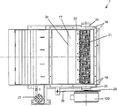
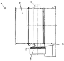
図1a〜cは、例えば、木材、紙、プラスチック素材などの廃棄物のために使用することができる、この発明による粉砕設備1の例を図示している。この設備は、粉砕シャフト20が、ベアリング25を用いて固定されている筐体10を有する一方、粉砕器具21は、軸方向に対して間隔を開けた形で粉砕シャフトの周囲に配置されている。粉砕室は、テーブル17と壁面部16とによって境界を規定されている。粉砕器具21は、横方向ブレード部材22の形の静止した対抗手段と協力して動作する。トルク支持体30を介して筐体10上に支持されている駆動ユニット100は、一端を粉砕シャフト20に取り付けられている。粉砕する素材は、壁面部16により境界を規定された粉砕室に対して、上方からテーブル面17上に落ちて来て、次に油圧駆動部23を用いて、水平方向に移動させることが可能なスライダー24によって、粉砕器具に供給される。スライダー24が、粉砕シャフトに最も近い位置に達した後、スライダーは、再び引っ込められ、そうすることによって、別の粉砕する素材が、テーブル17上に落ちて来て、次にスライダーの移動方向が逆転した後、粉砕シャフトの方向に移動される。粉砕する素材は、図1aの平面図に関して下方に落ちて来て、それぞれの場合に関連した特定の実施形態に依存して、そこに集められるか、或いは運び去られる。図1aは、この設備の平面図を図示している一方、図1bは、この発明により構成された粉砕設備の側面図を、図1cは、その前面図を示している。
FIGS. 1 a-c illustrate an example of a grinding facility 1 according to the invention that can be used for waste such as, for example, wood, paper, plastic materials. This equipment has a
しかし、図示されていない実施形態では、横方向部材は、供給される素材の粉砕により力が発生する場合にのみ静止するようにすることができる一方、例えば、供給素材内で粉砕することができない異物の結果として、それらの力が過剰となった場合に、横方向部材が、その弾性的な取付のために曲がって、粉砕器具への損傷を防止するようにすることも可能である。 However, in an embodiment not shown, the transverse member can be stationary only when a force is generated by crushing the supplied material, while it cannot be crushed, for example, in the supplied material. If these forces become excessive as a result of foreign objects, it is also possible for the transverse members to bend due to their elastic attachment so as to prevent damage to the grinding tool.
図1に図示した設備は、遊星歯車伝動装置を統合した24極式三相同期モーターを備えた駆動ユニット100を有し、その際伝動装置の駆動出力シャフトは、中空軸の形をしており、そこに設備のシャフト又は粉砕シャフト20が押し込まれている。従って、粉砕シャフトによって保持、支持される駆動ユニットに対して、特別な取付構成は規定されない。可変周波数で動作する三相同期モーターは、永久磁石を持つ内部回転子を有し、それに対して、この回転子は、半径方向に対して内側の位置に遊星歯車伝動装置を収容して、駆動ユニット100用の図面に図示されたコンパクトな構造を可能としている。同期モーターが、伝動構造を完全に収容しているので、駆動ユニット全体は、この特別な設計構成により、同期モーター用に対応した筐体よりも大きくなることはない共通の筐体によって取り囲まれている。図面からは分からないが、この粉砕設備は、制御機器によって制御された周波数変換器を有し、それを用いて、モーター及びそれにより設備のシャフトの回転速度を制御している。ここで述べる実施形態では、一段式遊星歯車伝動装置は、1:5の一定の減速比を有する。その結果、トルクモーターとも称される電気モーターのトルクは、モーターの駆動出力シャフトにおけるトルクと比べて、5倍に増大される。
1 has a
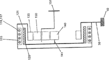
以下において、この発明による図1に図示した粉砕設備の駆動ユニット100の基本部の構造を記述する。図2bは、駆動ユニットの基本部を模式的な構造で図示した側面図である一方、図2aは、平面図である。駆動ユニット100の重要な構成部品は、モーター巻線116と積層板パック117を取り囲む、三相同期モーターの固定子115である。この固定子と同様に、ほぼ回転対称形であり、固定子と対向する側面上に永久磁石121を有する回転子120が、半径方向に対して内側に配置されている。遊星歯車伝動装置が、固定子115に対して内側に配置され、軸方向に対して、固定子によって完全に覆われており、この装置の構成部分は、図2aと2bにシンボルで図示されている。既に述べた通り、同期モーターの固定子と接続される伝動用円環部135が、半径方向に対して、回転子120に隣接して配置されている。図2bにも図示されている通り、電気モーターの回転子120は、太陽歯車140を保持する太陽歯車シャフト141と固定的に接続されている。図示した実施形態では、遊星歯車伝動装置は、遊星歯車保持体152によって保持された三つの遊星歯車150を有する。伝動用駆動出力シャフトは、設備のシャフトと連結された遊星歯車保持シャフト151によって実現されている(図1参照)。駆動ユニットと固定子115の筐体は、トルク支持体30を介して、この設備の筐体10と接続されている。
Hereinafter, the structure of the basic part of the
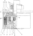
図3は、図2でシンボルを用いて図示されている駆動ユニットをより詳細に示した半断面図であり、この場合、同じ構成部品には同じ符号を使用している。図から明らかに分かる通り、円環部135は、ねじ込み式接続部51,50を介して、それぞれ筐体10及び固定子115と固定的に接続されている。駆動部の筐体は、トルク支持体30を介して、粉砕設備の筐体上で支持されている(図1aと1bを参照)。回転子120上に半径方向に対して外側に取り付けられた永久磁石121は、磁界に関して、回転子の同期回転用のモーター巻線の回転磁界と協力して動作する。回転子は、ねじ込み式接続部53を介して、遊星歯車伝動装置の太陽歯車140と接続されており、太陽歯車は、ベアリング60を用いて、筐体10上で支持されている。回転子120は、静止した円環部135に対して、同様にベアリング61を用いて支持されている。遊星歯車保持シャフト151は、伝動用駆動出力シャフトとして、中空軸の形で筐体10から外側に突き出ている。図面に図示されている通り、設備のシャフト20、即ち、粉砕シャフトは、中空の伝動用駆動出力シャフトに挿入されて、制限部材70を用いて固定されている。この制限部材は、中空軸を外側から取り囲むリングを有し、そのリング内には、軸方向に対して、ねじ70で固定された、逆方向に細くなっているスリーブが配置されており、こうするによって、シャフトの方向に沿って半径方向に押え付ける力を生み出している。この駆動部は、設備のシャフトによって、直接支持又は保持されている。中空の駆動出力シャフト、即ち、遊星歯車保持シャフトと、設備のシャフトとの間のトルクの伝達は、それぞれの実施形態に依存して、制限部材70によって生み出される大きな圧力による摩擦式軸止関係か、例えば、シャフト上に互いに係合し合う形の内歯/外歯構成による明確な軸止関係のどちらかで行われる。後者の場合、制限部材は、設備の動作時に、中空軸と設備のシャフトとの間の組み立てるために必要な遊びを除去する役割を果たす。遊星歯車伝動装置の駆動出力シャフトと粉砕シャフト間に、その他の接続方法を使用することも可能であることが好ましい。
FIG. 3 is a half sectional view showing the drive unit shown in FIG. 2 using symbols in more detail, in which the same reference numerals are used for the same components. As can be clearly seen from the figure, the
この発明による図1aに図示された粉砕設備から出発して、別の実施形態では、図3に図示した前記の駆動ユニットを粉砕シャフト20の第二の端部にも連結するものと規定し、そうすることによって、回転速度を低下させることなく、粉砕用に提供されるトルクを二倍にすることができる。更に、この発明では、粉砕設備に複数の粉砕シャフトを配備するものとし、その場合、駆動ユニットは、それらの中の少なくとも一つと連結され、多極式三相同期モーター(トルクモーター)は、半径方向に対して内側の位置に配置されて、少なくとも一対の遊星歯車伝動装置、特に一対の一段式遊星歯車伝動装置を取り囲むものとする。
Starting from the grinding facility illustrated in FIG. 1a according to the invention, in another embodiment, it is provided that the drive unit illustrated in FIG. 3 is also connected to the second end of the grinding
この発明の別の実施形態では、同期モーターによって取り囲まれた遊星歯車伝動装置は、太陽歯車140又は太陽歯車シャフト141が固定子115又は伝動装置用筐体と接続された形に配置されるものと規定することができる(図4参照)。図4でシンボルを用いて図示された、この発明による粉砕設備の別の実施形態にもとづく駆動ユニットでは、遊星歯車シャフトは、例えば、前記のトルク支持体30を介して、筐体10と固定的に接続される。又もや、遊星歯車保持シャフト151は、伝動用駆動出力シャフトとして、即ち、(図示されていない)粉砕シャフトと固定する役割を果たす。この場合、図2bに図示した駆動ユニットと違って、遊星歯車伝動装置の伝動用円環部135は、回転子120、即ち、同期モーターの回転子部材と共に動く。従って、この円環部は、回転子の磁石構造と固定的に接続されて、それと共に動く。回転子が、円環部と統合されている、或いは関連した部品の形であるので、このことは、部品数及び所要の分離又は取付位置に関して利点を提供するものである。
In another embodiment of the present invention, the planetary gear transmission surrounded by the synchronous motor is arranged such that the
1 粉砕設備
10 粉砕設備の筐体
16 壁面部
17 テーブル
20 粉砕シャフト、設備のシャフト
21 粉砕器具
22 横方向ブレード部材
23 油圧シャフト、油圧駆動部
24 スライダー
25 ベアリング
30 トルク支持体
50,51,52,53 ねじ込み式接続部
60,61,62 ベアリング
70 制限部材
71 ねじ
100 駆動ユニット
105 駆動部の筐体
110 三相同期モーター
115 固定子
116 モーター巻線
117 積層板パック
120 回転子
121 永久磁石
135 伝動用円環部
140 太陽歯車
141 太陽歯車シャフト
150 遊星歯車
151 アーム保持シャフト、遊星歯車保持シャフト
152 遊星歯車保持部
DESCRIPTION OF SYMBOLS 1
Claims (13)
この電気モーターは、制御機器によって制御される周波数変換器の出力と電気的に接続された多極式三相同期モーター(110)の形であることと、
この伝動装置は、少なくとも一つの太陽歯車(140)と、一つの円環部(135)と、複数の遊星歯車(150)とを有する遊星歯車伝動装置の形であり、三相同期モーターが、この遊星歯車伝動装置を少なくとも部分的に取り囲み、モーターと伝動装置が、共通の筐体(10)内に配置されており、この同期モーターの回転子(120)が、固定的に、或いは連結機器を用いて、太陽歯車(140)と接続されるとともに、この同期モーターの固定子(115)と、共通の筐体(10)と、遊星歯車伝動装置の円環部(135)とが、互いに固定的に接続されていることと、
を特徴とする粉砕設備。 In operation, it has at least one drive unit (100) with an electric motor connected via a transmission to a grinding shaft (20) with a grinding tool (21) around it, In the crushing facility (1) for waste and / or production residue, which crushes the material to be treated in cooperation with the counter means (22),
This electric motor is in the form of a multi-pole three-phase synchronous motor (110) electrically connected to the output of the frequency converter controlled by the control device;
This transmission is in the form of a planetary gear transmission having at least one sun gear (140), one annular portion (135), and a plurality of planetary gears (150) , and a three-phase synchronous motor is The planetary gear transmission is at least partially surrounded, the motor and the transmission are arranged in a common housing (10), and the rotor (120) of the synchronous motor is fixed or connected. And the stator (115) of the synchronous motor, the common casing (10), and the annular part (135) of the planetary gear transmission are connected to each other. A fixed connection ,
Crushing equipment characterized by.
Applications Claiming Priority (2)
| Application Number | Priority Date | Filing Date | Title |
|---|---|---|---|
| DE102005037668A DE102005037668B4 (en) | 2005-08-05 | 2005-08-05 | Crushing device with three-phase synchronous motor and integrated planetary gear stage |
| DE102005037668.1 | 2005-08-05 |
Publications (2)
| Publication Number | Publication Date |
|---|---|
| JP2007044690A JP2007044690A (en) | 2007-02-22 |
| JP4808564B2 true JP4808564B2 (en) | 2011-11-02 |
Family
ID=36964137
Family Applications (1)
| Application Number | Title | Priority Date | Filing Date |
|---|---|---|---|
| JP2006209749A Expired - Fee Related JP4808564B2 (en) | 2005-08-05 | 2006-08-01 | Grinding equipment with three-phase synchronous motor and planetary gear transmission integrated with it |
Country Status (8)
| Country | Link |
|---|---|
| US (1) | US7469850B2 (en) |
| EP (1) | EP1749576B1 (en) |
| JP (1) | JP4808564B2 (en) |
| AT (1) | ATE380593T1 (en) |
| CA (1) | CA2555434C (en) |
| DE (2) | DE102005037668B4 (en) |
| DK (1) | DK1749576T3 (en) |
| ES (1) | ES2299123T3 (en) |
Families Citing this family (13)
| Publication number | Priority date | Publication date | Assignee | Title |
|---|---|---|---|---|
| DE102006043179A1 (en) * | 2006-09-14 | 2008-03-27 | Siemens Ag | Mill for grinding coarse, stone-like bulk material with axis-parallel drive |
| US8470071B2 (en) * | 2006-09-25 | 2013-06-25 | Dais Analytic Corporation | Enhanced HVAC system and method |
| GB2453674A (en) * | 2007-05-18 | 2009-04-15 | Vernacare Ltd | A macerator having a multi-phase motor to drive blade means |
| EP2204895A1 (en) | 2009-01-02 | 2010-07-07 | Siemens Aktiengesellschaft | Drive unit for an atomisation machine and atomisation machine |
| EP2216097B1 (en) | 2009-02-09 | 2012-04-18 | Siemens Aktiengesellschaft | Grinding machine with a disc motor |
| DE102009010640A1 (en) | 2009-02-26 | 2010-09-02 | Siemens Aktiengesellschaft | Coupling system for use in comminution machine, has pressing elements connected with electrical machine and rotational body, respectively, where torque acting on body is limited by co-operation of one of elements with another element |
| DE102009021391B4 (en) * | 2009-05-14 | 2015-07-16 | Siempelkamp Maschinen- Und Anlagenbau Gmbh | Continuous press |
| DE102009035247A1 (en) | 2009-07-29 | 2011-02-03 | Biotec Sistemi S.R.L. | Pulper with torque motor |
| DE202011103675U1 (en) | 2011-07-26 | 2012-11-08 | Doppstadt Familienholding Gmbh | comminution device |
| CN102824947B (en) * | 2012-07-20 | 2014-10-15 | 东莞市邦泽电子有限公司 | Paper shredder using permanent magnet synchronous motor |
| DE102013114782B3 (en) * | 2013-12-23 | 2015-04-02 | Vecoplan Ag | Crushing device with a three-phase asynchronous motor and a frictional traction mechanism gear and method for its operation |
| US9562322B1 (en) | 2014-07-03 | 2017-02-07 | Bouldin Corporation | Fibrous material reprocessing |
| WO2021115517A1 (en) * | 2019-12-11 | 2021-06-17 | Schaeffler Technologies AG & Co. KG | Discharge device for discharging an electrical charge from a rotor of an electric motor |
Family Cites Families (14)
| Publication number | Priority date | Publication date | Assignee | Title |
|---|---|---|---|---|
| DE826839C (en) * | 1950-02-03 | 1952-01-07 | Scheffel Maschinenfabrik W | Meat cutting machine |
| IT1119222B (en) * | 1979-10-16 | 1986-03-03 | Sant Andrea Novara Officine | SHREDDING MACHINE |
| EP0064596B1 (en) * | 1981-05-07 | 1986-07-02 | Colortronic Reinhard GmbH + Co.KG | Granulating mill for comminuting runners, moulded parts, blown hollow bodies, etc. |
| GB2215235B (en) * | 1988-02-25 | 1992-02-05 | Ofrex Group Holdings Plc | Improvements relating to shredding machines |
| DE8915534U1 (en) * | 1989-09-28 | 1990-09-06 | Vecoplan GmbH Maschinenfabrik, 5439 Bad Marienberg | Waste shredding device |
| JPH0533662U (en) * | 1991-10-09 | 1993-04-30 | コパル電子株式会社 | Rotary motor with reduction gear |
| JPH1042519A (en) * | 1996-07-18 | 1998-02-13 | Sankyo Seiki Mfg Co Ltd | Motor |
| JP3659546B2 (en) * | 1997-06-27 | 2005-06-15 | 日立建機株式会社 | Crusher |
| JP2000070749A (en) * | 1998-09-03 | 2000-03-07 | Matsui Mfg Co | Crusher |
| DE10130446A1 (en) * | 2001-06-23 | 2003-01-09 | Sauter Kg Feinmechanik | tool turret |
| DE10223811B4 (en) * | 2002-05-28 | 2007-05-03 | Knoll Maschinenbau Gmbh | Cutting device, in particular for chipping chips |
| DE20313327U1 (en) * | 2003-07-23 | 2003-11-13 | Vecoplan Maschinenfabrik GmbH & Co. KG, 56470 Bad Marienberg | A waste material shredding machine has the shredding roller directly coupled to frequency controlled electric motors with sensors governing the speed of rotation. |
| DE10333359B3 (en) * | 2003-07-23 | 2005-01-20 | Vecoplan Maschinenfabrik Gmbh & Co. Kg | A waste material shredding machine has the shredding roller directly coupled to frequency controlled electric motors with sensors governing the speed of rotation. |
| DE102005062963A1 (en) * | 2005-12-28 | 2007-07-12 | Vecoplan Maschinenfabrik Gmbh & Co. Kg | Crushing device with reduced bearing numbers |
-
2005
- 2005-08-05 DE DE102005037668A patent/DE102005037668B4/en not_active Expired - Fee Related
-
2006
- 2006-07-18 ES ES06014873T patent/ES2299123T3/en active Active
- 2006-07-18 DE DE502006000217T patent/DE502006000217D1/en active Active
- 2006-07-18 EP EP06014873A patent/EP1749576B1/en not_active Not-in-force
- 2006-07-18 DK DK06014873T patent/DK1749576T3/en active
- 2006-07-18 AT AT06014873T patent/ATE380593T1/en active
- 2006-07-31 US US11/461,076 patent/US7469850B2/en not_active Expired - Fee Related
- 2006-08-01 JP JP2006209749A patent/JP4808564B2/en not_active Expired - Fee Related
- 2006-08-03 CA CA002555434A patent/CA2555434C/en not_active Expired - Fee Related
Also Published As
| Publication number | Publication date |
|---|---|
| DK1749576T3 (en) | 2008-05-05 |
| ATE380593T1 (en) | 2007-12-15 |
| CA2555434C (en) | 2008-09-02 |
| ES2299123T3 (en) | 2008-05-16 |
| JP2007044690A (en) | 2007-02-22 |
| CA2555434A1 (en) | 2007-02-05 |
| US20080223966A1 (en) | 2008-09-18 |
| EP1749576B1 (en) | 2007-12-12 |
| EP1749576A2 (en) | 2007-02-07 |
| US7469850B2 (en) | 2008-12-30 |
| DE102005037668B4 (en) | 2007-10-25 |
| DE502006000217D1 (en) | 2008-01-24 |
| DE102005037668A1 (en) | 2007-02-15 |
| EP1749576A3 (en) | 2007-02-21 |
Similar Documents
| Publication | Publication Date | Title |
|---|---|---|
| JP4808564B2 (en) | Grinding equipment with three-phase synchronous motor and planetary gear transmission integrated with it | |
| JP5403866B2 (en) | Grinding device with reduced bearing members | |
| US6925694B2 (en) | Tool turret | |
| JP5683465B2 (en) | Heavy-duty driving device and mill driven thereby | |
| US4044274A (en) | Transmission system | |
| CN102858459B (en) | Mill drive system | |
| JP2013200038A (en) | Transmission device having switching part operable by actuator having at least one electric part | |
| RU2538394C1 (en) | Geared engine for mill drive | |
| JP6676164B2 (en) | Variable speed gearbox and method for starting variable speed gearbox | |
| WO2016180750A1 (en) | A marine vessel propulsion device, a pod unit and a marine vessel. | |
| KR101619000B1 (en) | Drive arrangement for a vertical roller mill | |
| WO2012009085A2 (en) | Electric motor having a selectively adjustable base speed | |
| US20070200351A1 (en) | Plant facility | |
| US7547273B2 (en) | Drive device for screw centrifuges | |
| AU2003259599A1 (en) | Variable speed electric motors | |
| US7575186B2 (en) | Comminution machine | |
| US6431043B1 (en) | Mobile machine tool, especially table saw | |
| WO1997036362A1 (en) | Variable speed electromagnetic machine | |
| JP7483912B2 (en) | Rotating Electric Machine | |
| CN101508037A (en) | Large-torsion notching cutter | |
| CN110999048A (en) | Generators for wind energy installations and wind energy installations with generators | |
| US20200256432A1 (en) | Variable-speed speed-up gear | |
| EP2195136B1 (en) | Driving mechanism configuration of working machine, especially for machine-tool drive | |
| HK1156902A (en) | Heavy-duty drive arrangement and mill driven by the same |
Legal Events
| Date | Code | Title | Description |
|---|---|---|---|
| A621 | Written request for application examination |
Free format text: JAPANESE INTERMEDIATE CODE: A621 Effective date: 20070126 |
|
| A131 | Notification of reasons for refusal |
Free format text: JAPANESE INTERMEDIATE CODE: A131 Effective date: 20100413 |
|
| RD04 | Notification of resignation of power of attorney |
Free format text: JAPANESE INTERMEDIATE CODE: A7424 Effective date: 20100525 |
|
| A601 | Written request for extension of time |
Free format text: JAPANESE INTERMEDIATE CODE: A601 Effective date: 20100712 |
|
| A602 | Written permission of extension of time |
Free format text: JAPANESE INTERMEDIATE CODE: A602 Effective date: 20100715 |
|
| A521 | Request for written amendment filed |
Free format text: JAPANESE INTERMEDIATE CODE: A523 Effective date: 20101001 |
|
| A131 | Notification of reasons for refusal |
Free format text: JAPANESE INTERMEDIATE CODE: A131 Effective date: 20110517 |
|
| A521 | Request for written amendment filed |
Free format text: JAPANESE INTERMEDIATE CODE: A523 Effective date: 20110623 |
|
| TRDD | Decision of grant or rejection written | ||
| A01 | Written decision to grant a patent or to grant a registration (utility model) |
Free format text: JAPANESE INTERMEDIATE CODE: A01 Effective date: 20110809 |
|
| A01 | Written decision to grant a patent or to grant a registration (utility model) |
Free format text: JAPANESE INTERMEDIATE CODE: A01 |
|
| A61 | First payment of annual fees (during grant procedure) |
Free format text: JAPANESE INTERMEDIATE CODE: A61 Effective date: 20110817 |
|
| FPAY | Renewal fee payment (event date is renewal date of database) |
Free format text: PAYMENT UNTIL: 20140826 Year of fee payment: 3 |
|
| R150 | Certificate of patent or registration of utility model |
Free format text: JAPANESE INTERMEDIATE CODE: R150 |
|
| R250 | Receipt of annual fees |
Free format text: JAPANESE INTERMEDIATE CODE: R250 |
|
| LAPS | Cancellation because of no payment of annual fees |