JP4790107B2 - Printer - Google Patents
Printer Download PDFInfo
- Publication number
- JP4790107B2 JP4790107B2 JP2000314329A JP2000314329A JP4790107B2 JP 4790107 B2 JP4790107 B2 JP 4790107B2 JP 2000314329 A JP2000314329 A JP 2000314329A JP 2000314329 A JP2000314329 A JP 2000314329A JP 4790107 B2 JP4790107 B2 JP 4790107B2
- Authority
- JP
- Japan
- Prior art keywords
- printer
- head
- belt
- ink
- recovery
- Prior art date
- Legal status (The legal status is an assumption and is not a legal conclusion. Google has not performed a legal analysis and makes no representation as to the accuracy of the status listed.)
- Expired - Fee Related
Links
- 238000011084 recovery Methods 0.000 claims description 214
- 238000012545 processing Methods 0.000 claims description 133
- 238000007599 discharging Methods 0.000 claims description 3
- 238000012986 modification Methods 0.000 description 26
- 230000004048 modification Effects 0.000 description 26
- 239000006096 absorbing agent Substances 0.000 description 25
- 239000007788 liquid Substances 0.000 description 18
- 238000000034 method Methods 0.000 description 18
- 239000002699 waste material Substances 0.000 description 18
- 238000003780 insertion Methods 0.000 description 15
- 230000037431 insertion Effects 0.000 description 15
- 238000012360 testing method Methods 0.000 description 14
- 239000000758 substrate Substances 0.000 description 13
- 238000004140 cleaning Methods 0.000 description 8
- 238000012937 correction Methods 0.000 description 8
- 238000010586 diagram Methods 0.000 description 8
- 230000006870 function Effects 0.000 description 8
- 238000001514 detection method Methods 0.000 description 7
- 210000000078 claw Anatomy 0.000 description 5
- 238000001035 drying Methods 0.000 description 5
- 239000003086 colorant Substances 0.000 description 4
- 230000000694 effects Effects 0.000 description 4
- XEEYBQQBJWHFJM-UHFFFAOYSA-N Iron Chemical group [Fe] XEEYBQQBJWHFJM-UHFFFAOYSA-N 0.000 description 3
- 230000005856 abnormality Effects 0.000 description 3
- 230000001276 controlling effect Effects 0.000 description 3
- 230000002093 peripheral effect Effects 0.000 description 3
- 230000036544 posture Effects 0.000 description 3
- 238000003825 pressing Methods 0.000 description 3
- 239000007787 solid Substances 0.000 description 3
- 230000002159 abnormal effect Effects 0.000 description 2
- 238000010521 absorption reaction Methods 0.000 description 2
- 239000003550 marker Substances 0.000 description 2
- 238000000926 separation method Methods 0.000 description 2
- 238000012546 transfer Methods 0.000 description 2
- 241001433879 Camarea Species 0.000 description 1
- 238000005452 bending Methods 0.000 description 1
- 230000007547 defect Effects 0.000 description 1
- 230000003111 delayed effect Effects 0.000 description 1
- 230000000881 depressing effect Effects 0.000 description 1
- 230000008030 elimination Effects 0.000 description 1
- 238000003379 elimination reaction Methods 0.000 description 1
- 238000010438 heat treatment Methods 0.000 description 1
- 238000011086 high cleaning Methods 0.000 description 1
- 238000012423 maintenance Methods 0.000 description 1
- 238000004519 manufacturing process Methods 0.000 description 1
- 230000002265 prevention Effects 0.000 description 1
- 230000001105 regulatory effect Effects 0.000 description 1
- 238000012958 reprocessing Methods 0.000 description 1
- 238000001179 sorption measurement Methods 0.000 description 1
- 238000011144 upstream manufacturing Methods 0.000 description 1
Images


Classifications
-
- B—PERFORMING OPERATIONS; TRANSPORTING
- B41—PRINTING; LINING MACHINES; TYPEWRITERS; STAMPS
- B41J—TYPEWRITERS; SELECTIVE PRINTING MECHANISMS, i.e. MECHANISMS PRINTING OTHERWISE THAN FROM A FORME; CORRECTION OF TYPOGRAPHICAL ERRORS
- B41J11/00—Devices or arrangements of selective printing mechanisms, e.g. ink-jet printers or thermal printers, for supporting or handling copy material in sheet or web form
- B41J11/0095—Detecting means for copy material, e.g. for detecting or sensing presence of copy material or its leading or trailing end
-
- B—PERFORMING OPERATIONS; TRANSPORTING
- B41—PRINTING; LINING MACHINES; TYPEWRITERS; STAMPS
- B41J—TYPEWRITERS; SELECTIVE PRINTING MECHANISMS, i.e. MECHANISMS PRINTING OTHERWISE THAN FROM A FORME; CORRECTION OF TYPOGRAPHICAL ERRORS
- B41J11/00—Devices or arrangements of selective printing mechanisms, e.g. ink-jet printers or thermal printers, for supporting or handling copy material in sheet or web form
- B41J11/007—Conveyor belts or like feeding devices
-
- B—PERFORMING OPERATIONS; TRANSPORTING
- B41—PRINTING; LINING MACHINES; TYPEWRITERS; STAMPS
- B41J—TYPEWRITERS; SELECTIVE PRINTING MECHANISMS, i.e. MECHANISMS PRINTING OTHERWISE THAN FROM A FORME; CORRECTION OF TYPOGRAPHICAL ERRORS
- B41J11/00—Devices or arrangements of selective printing mechanisms, e.g. ink-jet printers or thermal printers, for supporting or handling copy material in sheet or web form
- B41J11/008—Controlling printhead for accurately positioning print image on printing material, e.g. with the intention to control the width of margins
-
- B—PERFORMING OPERATIONS; TRANSPORTING
- B41—PRINTING; LINING MACHINES; TYPEWRITERS; STAMPS
- B41J—TYPEWRITERS; SELECTIVE PRINTING MECHANISMS, i.e. MECHANISMS PRINTING OTHERWISE THAN FROM A FORME; CORRECTION OF TYPOGRAPHICAL ERRORS
- B41J11/00—Devices or arrangements of selective printing mechanisms, e.g. ink-jet printers or thermal printers, for supporting or handling copy material in sheet or web form
- B41J11/0085—Using suction for maintaining printing material flat
-
- B—PERFORMING OPERATIONS; TRANSPORTING
- B41—PRINTING; LINING MACHINES; TYPEWRITERS; STAMPS
- B41J—TYPEWRITERS; SELECTIVE PRINTING MECHANISMS, i.e. MECHANISMS PRINTING OTHERWISE THAN FROM A FORME; CORRECTION OF TYPOGRAPHICAL ERRORS
- B41J2/00—Typewriters or selective printing mechanisms characterised by the printing or marking process for which they are designed
- B41J2/005—Typewriters or selective printing mechanisms characterised by the printing or marking process for which they are designed characterised by bringing liquid or particles selectively into contact with a printing material
- B41J2/01—Ink jet
- B41J2/135—Nozzles
- B41J2/165—Prevention or detection of nozzle clogging, e.g. cleaning, capping or moistening for nozzles
- B41J2/16585—Prevention or detection of nozzle clogging, e.g. cleaning, capping or moistening for nozzles for paper-width or non-reciprocating print heads
- B41J2/16588—Print heads movable towards the cleaning unit
-
- B—PERFORMING OPERATIONS; TRANSPORTING
- B41—PRINTING; LINING MACHINES; TYPEWRITERS; STAMPS
- B41J—TYPEWRITERS; SELECTIVE PRINTING MECHANISMS, i.e. MECHANISMS PRINTING OTHERWISE THAN FROM A FORME; CORRECTION OF TYPOGRAPHICAL ERRORS
- B41J2/00—Typewriters or selective printing mechanisms characterised by the printing or marking process for which they are designed
- B41J2/005—Typewriters or selective printing mechanisms characterised by the printing or marking process for which they are designed characterised by bringing liquid or particles selectively into contact with a printing material
- B41J2/01—Ink jet
- B41J2/17—Ink jet characterised by ink handling
- B41J2/1721—Collecting waste ink; Collectors therefor
-
- B—PERFORMING OPERATIONS; TRANSPORTING
- B41—PRINTING; LINING MACHINES; TYPEWRITERS; STAMPS
- B41J—TYPEWRITERS; SELECTIVE PRINTING MECHANISMS, i.e. MECHANISMS PRINTING OTHERWISE THAN FROM A FORME; CORRECTION OF TYPOGRAPHICAL ERRORS
- B41J2/00—Typewriters or selective printing mechanisms characterised by the printing or marking process for which they are designed
- B41J2/005—Typewriters or selective printing mechanisms characterised by the printing or marking process for which they are designed characterised by bringing liquid or particles selectively into contact with a printing material
- B41J2/01—Ink jet
- B41J2/135—Nozzles
- B41J2/165—Prevention or detection of nozzle clogging, e.g. cleaning, capping or moistening for nozzles
- B41J2/16517—Cleaning of print head nozzles
- B41J2/1652—Cleaning of print head nozzles by driving a fluid through the nozzles to the outside thereof, e.g. by applying pressure to the inside or vacuum at the outside of the print head
- B41J2/16532—Cleaning of print head nozzles by driving a fluid through the nozzles to the outside thereof, e.g. by applying pressure to the inside or vacuum at the outside of the print head by applying vacuum only
Landscapes
- Ink Jet (AREA)
- Handling Of Sheets (AREA)
- Common Mechanisms (AREA)
Description
【0001】
【発明の属する技術分野】
本発明は、複数のノズルよりインク滴を吐出してプリントを行うプリンタの構造に関する。
【0002】
【従来の技術】
従来のコンシューマ用途の既存のプリンタとして、複数のノズルより微小インク滴を吐出してプリントを行う、所謂、インクジェットプリンタは、ヘッドを主走査方向(用紙幅方向)に走査して印字を行うヘッド走査型のものが一般的である。このヘッド走査型のプリンタに適用されるプリンタヘッドは、副走査方向(用紙送り方向)と同一方向、あるいは、傾斜した方向に沿う複数のノズルを有しており、そのプリンタヘッドを主走査方向に走査して用紙全幅のプリントを行う。
【0003】
したがって、送り駆動機構としてプリンタヘッドの主走査方向の走査駆動機構と紙送り機構とを必要とし、駆動機構部が複雑化するとともにプリント速度の高速化が制限されていた。
【0004】
そこで、駆動機構部の簡略化とプリント速度の高速化が可能なものとしてプリンタヘッドの主走査方向駆動が不要であるフルラインインクジェットプリンタが考えられる。このフルラインインクジェットプリンタでは、紙幅分の印字幅を有するフルラインヘッドを有し、1パスで印字を行う。そして、用紙紙幅方向の一ライン分を同時に印字するため、ヘッド走査が全く必要なく、用紙紙を一方向に、間欠的、または、連続的に搬送しながら1ラインずつ順次印字することになる。
【0005】
上記フルラインインクジェットプリンタでは、用紙幅を1パスで印字するプリンタヘッドを有しており、多数のチャンネルの各ノズルのインク吐出面を常に目詰まり等が無く良好な状態に保つためのインク吐出面回復装置を組み込む必要がある。
【0006】
【発明が解決しようとする課題】
しかし、上記従来のフルラインプリント式インクジェットプリンタでは、ノズルの数が極めて多いために上記吐出面回復装置の占有スペ−スが大型化し、また、インク吐出面全域を確実にクリーニングするには、複雑な駆動方式を採用しなければならないなどの点からプリンタ装置として大型化が避けられず、また、価格的にも不利になることは免れない状態であった。
【0007】
また、上記従来のフルラインプリント式インクジェットプリンタでは、各ノズルの位置を正確に配置する必要があるが、プリンタヘッドをいくつかのブロック分けて構成した場合には、その位置調整が面倒になり、保守,管理が困難となり、商品化も難しくなる。
【0008】
本発明は、上述の問題点を解決するためになされたものであって、複数のノズルよりインク滴を吐出してプリントを行うプリンタにおいて、インク吐出面の回復処理が容易であり、その回復手段の構造も簡単であって、プリンタの大型化が避けられ、コストの低価格化も可能であり、また、調整や維持,管理等も容易であるプリンタを提供することを目的とする。
【0009】
【課題を解決するための手段】
本発明の請求項1記載のプリンタは、複数のノズルよりインク滴を吐出してプリントを行うプリンタにおいて、上記複数のノズルが配設されたインク吐出面を有するフルラインのプリンタヘッドと、印刷用紙を保持し、該印刷用紙を上記インク吐出面と対向するように搬送する少なくとも2つのローラに掛け渡された搬送ベルトと、上記プリントヘッドのノズルの吐出機能を回復させる回復手段と、上記回復手段によって上記プリントヘッドの回復処理を行う際、上記搬送ベルトにおける少なくとも上記インク吐出面と対向する部分を押し下げ、上記インク吐出面と上記搬送ベルトとの隙間をプリント時よりも拡大させるベルト移動手段と、上記ベルト移動手段によって形成された上記隙間に上記回復手段を移動させ、該回復手段を上記プリントヘッドと対向させる移動手段と、を有し、上記ベルト移動手段は、上記搬送ベルトの上記印刷用紙を保持する搬送面側に配置された一対のローラを有し、上記一対のローラを上記プリンタヘッドのインク吐出面から離間する方向に移動させることによって上記インク吐出面と上記搬送ベルトとの隙間をプリント時よりも拡大させることを特徴とする。
【0010】
本発明の請求項2記載のプリンタは、複数のノズルよりインク滴を吐出してプリントを行うプリンタにおいて、上記複数のノズルが配設されたインク吐出面を有するフルラインのプリンタヘッドと、印刷用紙を保持し、該印刷用紙を上記インク吐出面と対向するように搬送する少なくとも2つのローラに掛け渡された搬送ベルトと、上記プリントヘッドのノズルの吐出機能を回復させる回復手段と、上記回復手段によって上記プリントヘッドの回復処理を行う際、上記搬送ベルトにおける少なくとも上記インク吐出面と対向する部分を押し下げ、上記インク吐出面と上記搬送ベルトとの隙間をプリント時よりも拡大させるベルト移動手段と、上記ベルト移動手段によって形成された上記隙間に上記回復手段を移動させ、該回復手段を上記プリントヘッドと対向させる移動手段と、を有し、上記ベルト移動手段は、上記搬送ベルトの上記印刷用紙を保持する搬送面側に配置された一対の第1のローラと、上記搬送ベルトの上記搬送面と反対側の内面に配置された一対の第2のローラと、を有し、上記インク吐出面と上記搬送ベルトとの隙間をプリント時よりも拡大させる際、上記第1のローラを上記プリンタヘッドから離間する方向に、上記第2のローラを上記プリンタヘッドへ接近する方向にそれぞれ移動させることを特徴とする。
【0011】
本発明の請求項3記載のプリンタは、複数のノズルよりインク滴を吐出してプリントを行うプリンタにおいて、上記複数のノズルが配設されたインク吐出面を有するフルラインのプリンタヘッドと、印刷用紙を保持し、該印刷用紙を上記インク吐出面と対向するように搬送する少なくとも2つのローラに掛け渡された搬送ベルトと、上記プリントヘッドのノズルの吐出機能を回復させる回復手段と、上記回復手段によって上記プリントヘッドの回復処理を行う際、上記搬送ベルトにおける少なくとも上記インク吐出面と対向する部分を押し下げ、上記インク吐出面と上記搬送ベルトとの隙間をプリント時よりも拡大させるベルト移動手段と、上記ベルト移動手段によって形成された上記隙間に上記回復手段を移動させ、該回復手段を上記プリントヘッドと対向させる移動手段と、を有し、上記ベルト移動手段は、上記搬送ベルトの上記印刷用紙を保持する搬送面側に配置された一対のローラを有し、上記インク吐出面と上記搬送ベルトとの隙間をプリント時よりも拡大させる際、上記一対のローラを上記プリンタヘッドから離間する方向に、上記搬送ベルトを掛け渡す上記2つのローラのうち一方のローラを他方のローラに近づく方向にそれぞれ移動させることを特徴とする。
【0012】
本発明の請求項4記載のプリンタは、請求項1乃至3のいずれか1項に記載のプリンタにおいて、上記回復手段は、プリント時、上記搬送ベルトに対して上記印刷用紙の搬送方向と直交する方向の側方に位置し、上記移動手段は、上記回復手段を上記搬送ベルトの上記印刷用紙を保持する搬送面に対して並行に、かつ、上記搬送方向に直交する方向から上記プリンタヘッドに対して出し入れすることを特徴とする。
【0013】
本発明の請求項5記載のプリンタは、請求項1乃至3のいずれか1項に記載のプリンタにおいて、上記ベルト移動手段によって上記インク吐出面と上記搬送ベルトとの隙間をプリント時よりも拡大させる際、上記搬送ベルトの搬送方向の周長が一定に保たれていることを特徴とする。
【0014】
本発明の請求項6記載のプリンタは、請求項1記載のプリンタにおいて、上記一対のローラは、プリント時、上記搬送ベルトと当接していることを特徴とする。
【0015】
本発明の請求項7記載のプリンタは、請求項2記載のプリンタにおいて、上記第1のローラ及び上記第2のローラは、プリント時、上記搬送ベルトと当接していることを特徴とする。
【0017】
本発明の請求項8記載のプリンタは、複数のノズルよりインクを吐出してプリントを行うプリンタにおいて、上記複数のノズルが排泄されたフルラインのプリンタヘッドと、
少なくとも2つのローラと、該2つのローラに掛け渡された無端状の搬送ベルトとを有し、上記プリンタヘッドの上記インク吐出面と対向して配置され、印刷用紙を搬送する用紙搬送手段と、上記プリンタヘッドのノズルの吐出機能を回復させる回復手段と、を備え、
上記回復手段によって上記プリントヘッドの回復処理を行う際、上記用紙搬送手段は、上記回復手段が上記プリントヘッドに対向できる空間を形成すべく、上記2つのローラうち一方のローラを、他方のローラに近づく方向にスライド移動させ、上記搬送ベルトを下方向に移動させることを特徴とする。
【0035】
【発明の実施の形態】
以下、本発明の実施の形態を図に基づいて説明する。
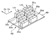
図1は、本発明のプリンタ10の基本システム構成図である。図2は、プリンタ10の印刷部周りの概要を示す縦断面図である。図3は、プリンタ10に適用される用紙搬送系の構造を示す斜視図である。図4は、プリンタ10に適用されるプリンタヘッドの分解斜視図である。図5は、上記プリンタヘッドを構成するヘッドユニットのノズル配置を示すインク吐出面側(図4のA側)からみた拡大図である。
【0036】
本プリンタ10は、全用紙幅に亘る複数のノズルより微小インク滴を吐出してプリントを行うインクジェットプリンタであり、このプリンタは、プリンタ全体の制御を司るプリント制御手段であるCPU1と、用紙搬送用の搬送ベルト18を有する用紙搬送手段である用紙搬送系2と、印刷画像データに基づき、4色のインク滴を吐出するプリンタヘッド3と、搬送ベルト18の上流側(供給側)に配設される印刷用紙(以下、用紙と記載)28の供給用の給紙トレイ4と、上記給紙トレイ4の出口に配設される用紙給紙手段である供給ローラ5と、搬送ベルト18の下流側(排出側)に配設される空気加熱式の乾燥手段である乾燥装置6と、搬送ベルト18の排出部分に配設される印刷済み用紙を収納するための排紙トレイ7と、搬送ベルト18の内側のプリンタヘッド3の下方対向位置に対して挿入、または、退避可能であって、用紙28を空気圧を介して吸引する吸着手段である吸着装置8と、搬送ベルト18の側方位置から、すなわち、搬送方向に直交する用紙幅方向から挿入可能な装置であって、プリンタヘッド3の吐出機能回復処理を行う回復手段である回復装置9と、上記用紙搬送系2の駆動ローラ17の駆動用モータ(M)12と、上記モータ12を駆動するモータドライバ11と、上記供給ローラ5の駆動用モータ(M)14と、上記モータ14を駆動するモータドライバ13と、上記プリンタヘッド3のインク滴の吐出をコントロールするヘッドコントローラ15とを有してなる。
【0037】
上記用紙搬送系2は、無端状(エンドレス状)の帯部材である上記搬送ベルト18と、搬送ベルト18を用紙28の幅方向(E0 )と直交する搬送方向(D0 )に駆動する駆動ローラ17および従動ローラ16と、ベルト搬送面に付着したインクを除去するクリーニング手段としてのクリーニング爪27と、各種センサとを有してなる。なお、クリーニング手段としては、インク吸収ローラ等を適用してもよい。
【0038】
上記搬送ベルト18には、用紙28を吸着するための吸気穴群18eと、搬送ベルト18の走行速度,位置を検出するための速度,位置標識である所定間隔の標識線18aと、用紙保持位置標識(用紙位置決め手段)である用紙先端位置標識18bとが設けられている。
【0039】
なお、上記吸気穴群18eは、用紙28が保持される用紙領域28Aより狭い範囲の吸気領域18Dに設けられる。上記用紙先端位置標識18bは、用紙28を上記用紙領域28Aに位置させるために後述の用紙先端位置センサ22の検出位置に合わせて付されている(図3参照)。
【0040】
上記用紙搬送系2はさらに、上記標識線18aの通過を検知して搬送ベルト18の搬送速度・位置を検出するベルト速度・位置検出センサ21と、上記用紙先端位置標識18bを検出する用紙位置決め手段である用紙先端位置センサ22と、用紙28の保持状態における搬送方向D0 に対する傾きを検出する2つの用紙傾き検出センサ23,24とを有している。
【0041】
上記プリンタヘッド3は、インクジェットタイプのプリンタヘッドであって、インク吐出制御用圧電素子群とインク滴の吐出ノズル列を有する複数のヘッドユニット35a,35b等で構成される。なお、吐出されるインクは、インクタンク25より供給される。その他の構造の詳細は、図4,5を用いて後で説明する。
【0042】
上記プリンタヘッド3の詳細な構造について説明すると、図4は、上記プリンタヘッドの分解斜視図であり。本図に示すように用紙搬送方向(D0 方向)に沿って配設される4つのヘッドブロック31,32,33,34からなる。上記各ヘッドブロックは、支持基板と、その支持基板に支持され、D0 方向に対して斜設される3ユニットずつの複列のヘッドユニットからなる。また、各プリンタユニットは、一対のノズル列ユニットからなり、インク滴吐出する圧電素子が組み込まれている。
【0043】
上記ヘッドブロック31は、ヘッド支持基板41と、ヘッド支持基板41の開口41aに保持されるヘッドユニット35a,35b,35cとヘッドユニット38d,38e,38fとからなる。
【0044】
上記ヘッドブロック32は、支持基板42と、支持基板42の開口42aに保持されるヘッドユニット36a,36b,36cとヘッドユニット35d,35e,35fとからなる。
【0045】
上記ヘッドブロック33は、支持基板43と、支持基板43の開口43aに保持されるヘッドユニット37a,37b,37cとヘッドユニット36d,36e,36fとからなる。
【0046】
上記ヘッドブロック34は、支持基板44と、支持基板44の開口44aに保持されるヘッドユニット38a,38b,38cとヘッドユニット37d,37e,37fとからなる。
【0047】
上記ヘッドブロック31とヘッドブロック32に分けて配設されるヘッドユニット35a,35b,35c,35d,35e,35fは、ブラック(B)のインクを吐出するユニットであり、D0 方向に対して傾斜する単一傾斜ラインLA に沿って配置される。
【0048】
上記ヘッドブロック32とヘッドブロック33に分けて配設されるヘッドユニット36a,36b,36c,36d,36e,36fは、イエロー(Y)のインクを吐出するユニットであり、D0 方向に対して傾斜する単一傾斜ラインLB に沿って配置される。
【0049】
上記ヘッドブロック33とヘッドブロック34に分けて配設されるヘッドユニット37a,37b,37c,37d,37e,37fは、マゼンダ(M)のインクを吐出するユニットであり、D0 方向に対して傾斜する単一傾斜ラインLC に沿って配置される。
【0050】
上記ヘッドブロック34とヘッドブロック31に分けて配設されるヘッドユニット38a,38b,38c,38d,38e,38fは、シアン(C)のインクを吐出するユニットであるが、D0 方向に対して傾斜する2つの傾斜ラインLD1とLD2に沿って配置される。
【0051】
プリンタヘッド3として組み立てられた状態では、上記各色別の複数のヘッドユニット、例えば、35a,35b,35c,35d,35e,35fにはそのインク吐出用のノズルが用紙28のE0 方向の有効印字幅(A4判の場合、210mm)に対してオーバーラップ部以外は所定のピッチδpでD0 方向に所定の傾斜角度に沿って(例えば、図4の傾斜ラインLA に沿って)配列されている。上記ピッチδpは、例えば、解像度400dpiとすると0.0635mmとなる。
【0052】
図5は、上記ヘッドブロックの一部である3つのヘッドユニットをインク吐出面39側からみた拡大図である。例えば、ヘッドブロック31においてヘッドユニット35aは、一対のノズル列ユニット35a1と35a2からなる。ヘッドユニット35bは、同様に一対のノズル列ユニット35b1と35b2からなる。ヘッドユニット35cは、同様に一対のノズル列ユニット35c1と35c2からなる。また、各ノズル列ユニットは、各ヘッドユニット間も含めてそれぞれD0 方向に距離δbだけ離間して配置される。
【0053】
一方のノズル列ユニット35a1のインク吐出面39には、np/2個のノズル35a1a ,35a1b ,……,35a1z がE0 方向のピッチ2δpで配設されている。他方のノズル列ユニット35a2のインク吐出面39にもnp/2個のノズル35a2a ,……,35a2z がピッチ2δpで配置されている。そして、上記ノズル35a2a ,……,35a2z は、それぞれ上記ノズル吐出口35a1a ,……,35a1z に対してピッチδp分ずれて配置されている。したがって、一対のノズル列ユニット35a1および35a2よりなるヘッドユニット35aには、npドットのノズルがピッチδpの間隔で配設されることになる。
【0054】
上記ヘッドユニット35aに続いてヘッドユニット35b、さらに、ヘッドユニット35cが、それぞれに配設されるノズルが、上述したようにD0 方向に距離δbだけ離間し、また、E0 方向には、距離δaだけオーバラップした状態でずらして配置される。上記オーバラップ距離δaは、印字ドット数としてδa/δp個分に相当する。さらに、ヘッドユニット35cに対してヘッドブロック32のヘッドユニット35dが同様の相対位置に配置され、また、ヘッドユニット35dに対してヘッドユニット35f、ヘッドユニット35fに対してヘッドユニット35eも同様の相対位置に配置される。なお、上記オーバーラップ量は、1ドット分以上あればよい。
【0055】
上記回復装置9は、プリンタ3のノズル列が配設されるヘッド吐出面39のインク滴吐出機能を回復させる回復処理、例えば、目詰まりの解消、または、予防を行う装置である。印字動作中には上記回復処理装置9は、搬送ベルト18の側方位置に退避させておき、回復処理装置9を外側方からE1 方向に移動させて搬送ベルト18の上方、かつ、プリンタヘッド下方に送り込んで回復処理を実行させる。
【0056】
以上のように構成された本プリンタ10における印字動作について説明すると、まず、印字開始に際して上記回復処理装置9によりプリンタヘッド3のインク吐出面の回復処理が実行される。
【0057】
その後、ベルト18上に等間隔に設けられた標識線18aの通過をベルト速度/位置センサ21で検出しながら搬送ベルト18が定速度駆動される。用紙先端位置検出センサ22により搬送ベルト18の用紙先端位置標識18bが検出されると、供給ローラ5が始動して用紙28が搬送ベルト18上の用紙領域28A位置に送り出される。用紙28は、吸着装置8により吸引穴群18eを介して上記用紙領域28A位置に保持され、搬送ベルト18と共にD0 方向に搬送される。
【0058】
用紙先端位置標識18b検出後の標識線18aの通過量をベルト速度・位置センサ21で検出することによって、用紙28の先端部がプリンタヘッド3の下部の所定位置に到達したことが検知されると、それ以降、搬送ベルト18の用紙走査方向であるD0 方向への移動に同期した状態で印字が開始される。すなわち、ヘッドコントローラ15を介してプリンタヘッド3の各色毎の用紙幅全域に亘って各ノズルのインク滴の吐出制御が印刷画像データ29に基づいて実行され、印字が行われる。
【0059】
上記印字時に搬送ベルト18の速度が万一変化した場合、ベルト速度/位置センサ21によりヘッドコントローラ15を介して各ヘッドユニットのノズルのインク滴の吐出タイミングが調整され、正常な印字が続行される。
【0060】
また、用紙傾き検出センサ23,24により用紙28の保持位置の傾き(斜行)が検出された場合、上記用紙の傾きに合わせて各ヘッドユニットのノズルのインク滴の吐出ノズル位置や吐出タイミングがコントロールされ、用紙上のインク吐出位置が調整される。但し、上記用紙の傾きが所定量以上であることが検出され、吐出タイミングで補正不可能となる場合は、インク滴の吐出を中断し、印字動作を停止させる。
【0061】
上記印字実行後、乾燥装置6によるインクの乾燥が行われた後、吸着装置8による吸着力を消滅させ、用紙28は排紙トレイ7に収納される。
【0062】
なお、上記プリンタヘッド3は、図5のノズル配置を示す図により説明したように上記各ヘッドユニット間にてノズル位置が用紙幅のE0 方向に所定量オーバーラップして配置されている。そのオーバーラップ部分でのインク滴の吐出は、2重になることから元の画像データに比較して当然濃くなってしまう。そこで、オーバーラップ部分でのインク滴の吐出に後述するような補正制御をかけ、印刷画像データと同一の濃度でヘッドつなぎ目の目立たない滑らかな印刷を得るようにする。
【0063】
以上、説明した第1の実施形態のプリンタ10によれば、従来のインクジェットプリンタのようにプリンタヘッドのE0 方向(主走査方向)の走査を行わないことから用紙28の搬送速度を速くすることが可能になり、印字速度の高速化が実現できる。また、プリンタヘッドのE0 方向駆動機構が不要であり、プリンタの機構部の構成が簡単になり、小型化や低コスト化が実現できる。
【0064】
また、プリンタヘッドとして連続した長尺のプリンタヘッドを適用せず複数のヘッドユニットを組み合わせて用紙幅に対応するプリンタヘッド3を構成したので製作が容易になり、後述する濃度むら補正技術により組み立て、調整も簡単に行える。
【0065】
上記プリンタヘッド3においては、色別にヘッドユニットをD0 方向に対する傾斜ラインLA 等に沿って配設したので、インク滴吐出制御における吐出するべきノズルのタイミング制御が単純となる。
【0066】
用紙搬送系としてプラテンローラ等を適用せずに駆動ローラで駆動する無端状の搬送ベルト18を適用することから搬送機構が複雑化せず、装置の小型化が可能になる。また、搬送方向の下流側に駆動ローラ17を配したので用紙搬送する側の搬送ベルトに常にテンションが作用し、たるみが生じることないので、精度のよい用紙搬送が行われる。
【0067】
用紙を所定位置に保持するために空気式吸着装置8を適用したので、用紙のずれが発生しにくく、印字ずれが生じにくい。また、搬送ベルト18上の吸引穴群18eが設けられている吸気領域18Dが用紙領域28Aより狭い範囲であり、用紙領域以外に吸気穴が設けられていない。したがって、インク滴吐出部分の空気が乱されることがなく、インク滴吐出方向が乱されず、精度のよい印字がなされる。
【0068】
なお、上述したノズルのオーバーラップなどによる印字濃度を補正するための上記インク滴の吐出補正制御の技術は、本出願人が先に出願した特願平10−353253号に詳細に記載されている。
【0069】
上述した本プリンタ10に適用されるプリンタヘッド3においては、1つのヘッドブロックに複数色(2色)のヘッドユニットが配置される複合色ヘッドブロックを採用しているが、その変形例として、単一色の複数のヘッドユニットからなる単色ヘッドブロックを組み合わせて多色のプリンタヘッドを構成することも可能である。
【0070】
図6は、上記変形例のプリンタヘッドにおける単色ヘッドブロックとしてのB(黒)ヘッドブロック48の斜視図である。このBヘッドブロック48には、D0 方向に傾斜する傾斜ラインLE1に沿って黒色のヘッドユニット35a,35b,35cが配設され、さらに、D0 方向に傾斜する傾斜ラインLE2に沿って黒色のヘッドユニット35d,35e,35fがヘッド支持基板49上に配設される。
【0071】
そして、ヘッドユニット35a,35b,35cおよび35d,35e,35fの相対的な配置置関係は、前記図5で説明したノズル位置に配置される。但し、ヘッドユニット35aと35dとは、そのノズル位置がE0 方向のライン上に位置するように配置され、さらに、ヘッドユニット35cと35dのE0 方向のノズル位置のオーバーラップ量は、図5に示した距離δaと同一とする。また、本変形例では、黒色のヘッドブロックについて説明したが、他の色のヘッドブロックの構成も同様である。
【0072】
次に、本発明の第1の実施形態のプリンタについて説明する。
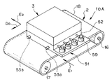
図7,8は、上記第1実施形態のプリンタ10Aの要部を示す斜視図であり、図7は、印刷待機、または、印字動作時であって回復処理装置が退避している状態を示し、図8は、回復処理装置がヘッド下部に挿入され、回復処理実行状態を示す。
【0073】
本実施形態のプリンタ10Aは、前述のプリンタ10に対してプリンタヘッド3が搬送ベルト18から離間する上方のF1 方向に移動可能であること、および、回復手段として搬送ベルト18の搬送側にて後述するE1 方向にスライド移動可能な回復手段である回復処理装置51を設けていることに特徴があり、それ以外の構成は、同一とする。なお、上記E1 方向は、用紙幅方向E0 方向に平行な方向とする。
【0074】
回復処理装置51は、ガイドピン53a,53bを有し、E1 方向にスライド移動可能な回復処理装置本体52と、その本体52内に組み込まれ、プリンタヘッド3の全てのヘッドユニット35a,35b,36a,36b…の吐出面にそれぞれ対応するキャップ手段であるキャップ54a,54b,55a,55b…と、上記キャップに連結される複数の廃液ポンプ59とを有してなる。なお、キャップ手段の他に吐出面をワイプする手段も加えてもよい。
【0075】
本プリンタ10Aにおいて、印字動作状態にあるときは、図7に示すように回復処理装置51は、搬送ベルト18の側方に退避している。プリンタヘッド面の回復処理を行う場合、まず、プリンタヘッド3を搬送ベルト18から離間するF1 方向に上昇させる。そこで、図8に示すように回復処理装置本体52をE1 方向にスライドさせて搬送ベルト18の上面のプリンタヘッド3の下部の回復処理可能な位置に移動させる。
【0076】
上記回復処理装置51の回復処理可能状態にあるとき、プリンタヘッド3のインク吐出面より上記各キャップ内にインクを吐出させ、各ノズルの目詰まり等のクリーニングを行う。吐出されたインクは、廃液ポンプ59を介して廃液タンク26(図2参照)に送られる。回復処理が終了すると、回復処理装置51を搬送ベルト18側方の位置に退避させ、プリンタヘッド3を降下させて印字可能状態にセットする。なお、プリンタ非使用状態では、上記各キャップによりヘッドユニット表面を覆った状態に保ち、ノズルの乾燥を防止する。
【0077】
本実施形態のプリンタ10Aによると、回復処理を行う場合、プリンタヘッド3の全インク吐出面について同時にクリーニングすることができ、すばやい回復処理が可能になる。また、印字動作時には回復処理装置51が搬送ベルト18上から退避しているので用紙搬送系2をコンパクトにまとめることができ、プリンタとして小型化が可能になる。
【0078】
次に、本発明の第2の実施形態のプリンタについて説明する。
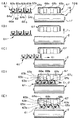
図9は、上記第2実施形態のプリンタ10Bの要部を示す斜視図であり、回復処理装置が退避した状態を示す。図10(A)〜(E)は、図9のB−B断面を示す図であって、回復処理の動作過程を示し、図10(A)は、印刷待機状態、または、印刷可能な状態であって、回復処理前の回復処理装置を退避させた状態を示す。図10(B)〜(E)は、回復処理の各動作状態を示す。図11は、上記回復処理装置に適用される回復処理装置本体のガイド板の要部を示す側面図であり、図12は、上記ガイド板のカム溝上のガイドピンの動作過程を示す拡大図である。
【0079】
本実施形態のプリンタ10Bは、前述のプリンタ10に対してプリンタヘッド67が搬送ベルト18から離間するF1 方向に移動可能であること、および、搬送ベルト18の上部にて搬送方向D0 と直交する用紙幅方向E0 方向に対して平行なE1 方向にスライドして挿入退避可能な回復処理装置61を設けていることに特徴があり、それ以外の構成は、同一とする。なお、上記用紙幅方向E0 方向は、用紙搬送方向D0 と直交する方向である。
【0080】
回復手段である回復処理装置61は、E1 方向に直交する両側面に配設されるガイドピン66a,66bを有し、E1 方向にスライド移動可能な回復処理装置本体62と、その本体62上に組み込まれ、プリンタヘッド67の各ヘッドユニット68a,68b,68cに対応して設けられる複数の回復ユニットと、上記装置本体62をガイドピン66a,66bを介してガイドするガイド板69とを有してなる(図10(A)参照)。
【0081】
上記複数の回復ユニットは、ヘッドユニットのインク吐出面を覆うことができる可撓性を有するキャップ手段であるキャップ部材63a,63b,63cと、上記キャップを上方向に付勢するバネ部材64a,64b,64cと、可撓性を有し、弾性変形状態で摺接してインク吐出面を払拭するワイプ手段であるワイパー65a,65b,65cとからなる(図10(A)参照)。なお、上記各ワイパーは、それぞれ対応する各キャップのE1 方向側に隣接して配置されている。
【0082】
上記ガイド板69は、プリンタ本体に対してE1 方向に直交する両側面に対向して支持され、図11に示すように装置本体62のガイドピン66a,66bが摺動自在に嵌入する2つのガイド溝69b,69c1,69c2,69d,69eとガイド溝69c1と69eの分岐部分に回転自在に装着される2つの切り換え爪69aとが設けられている。上記切り換え爪69aは、自重、または、付勢バネ(図示せず)により反時計回りに付勢されているものとする。
【0083】
なお、上記ガイド溝69bは、上記ガイドピン66aを最下位置に保持するカム溝領域Saを形成する。このときの回復処理装置61の高さは、ワイパー65a,65b,65cとキャップ部材63a,63b,63cが共にインク突出面に当接しない高さである。そして、このカム領域SaのE1 方向の有効長さは、用紙幅に相当する長さであって、回復装置61を搬送ベルトの外側方から上記ワイパーがワイプするべき各ヘッドの近傍まで移動させる長さとする。
【0084】
また、上記ガイド溝69c1は、上記ガイドピン66aを所定の上昇高さに保持するカム溝領域Sbを形成する。このときの回復処理装置61の高さは、ワイパー65a,65b,65cはインク吐出面に当接するがキャップ部材63a,63b,63cはインク吐出面に当接しない高さである。そして、このカム領域SbのE1 方向の有効長さは、ヘッド幅に相当する長さであって、回復装置61のワイパーが各ヘッド吐出面をワイプするだけの移動長さとする。
【0085】
また、上記ガイド溝69c2は、上記ガイドピン66aをガイド溝69c1より高い所定の上昇高さに保持するカム溝領域Scを形成する。このときの回復処理装置61の高さは、ワイパー65a,65b,65cとキャップ部材63a,63b,63cが共にインク吐出面に当接する高さである。そして、このカム領域ScのE1 方向の有効長さは、ワイプ処理後、上記キャップ部材がヘッド吐出面を覆う位置まで移動させるに必要な長さとする。
ガイドピン66bが嵌入するカム溝も上記と同様のカム溝領域を有する。
【0086】
以上の構成を有する本実施形態のプリンタ10Bの回復処理動作について説明すると、図10,11,12等を用いて説明する。
なお、回復処理装置61は、両側面にて各2つのガイドピン66aと66bにより図11のガイド板69でガイドされながら支持され、装置本体62が平行に保たれた状態で移動する。
【0087】
装置本体62が退避位置にあるとき(図10(A)の状態)、ガイドピン66a,66bは、それぞれガイド溝69bの端部に位置している(カム溝区間Saの外側)。
【0088】
回復処理を実行するに際して、まず、プリンタヘッド67を上方のF1 方向に所定量だけ上昇させる(図10(B)の状態)。
【0089】
そこで、回復処理装置61の装置本体62をプリンタヘッド67と搬送ベルト18との間に生じた隙間に向けてガイド板69にてガイドしながらE1 方向に移動させると(図10(C)の状態)、ガイドピン66a,66bは、ガイドピン切り換え爪69aに当接して、斜め上方向にガイドされ、上方に平行移動して、ガイド溝69c1のカム溝領域Sbの端部位置に到達する。この状態でワイパー65a,65b,65cの先端がインク吐出面に当接する(図10(D))。
【0090】
装置本体62をそのままE1 方向に移動させると、ガイドピン66a,66bは、ガイド溝69c1のカム溝領域Sb上を移動し、ワイパー65a,65b,65cがヘッドユニット68a,68b,68cのインク吐出面に当接したまま移動してインク吐出面が払拭され、クリーニングされる(図10(D)の状態で移動)。
【0091】
さらに、装置本体62をE1 方向に移動させると、ガイドピン66a,66bは、さらに上方に移動し、ガイド溝69c2のカム溝領域Scに到達するので、キャップ部材63a,63b,63cがバネ部材64a,64b,64cで上方に付勢された状態でヘッドユニット68a,68b,68cのインク吐出面に密着当接し、覆った状態とする(図10(E)の状態)。この状態でインクを上記キャップ中に吐出してノズルの目詰まりを解消する。印刷待機状態では上述のヘッドユニットをキャップで覆った状態を保持し、ノズル乾燥を防止する。
【0092】
その後、印刷開始に際して装置本体62をE1 方向に移動させると、ガイドピン66a,66bが傾斜ガイド溝69dで下方にガイドされて降下し、ワイパー65a,65b,65cとキャップ部材63a,63b,63cが共にヘッドユニット68a,68b,68cから離間する。そこで、装置本体62を反E1 方向に反転移動させると、ガイドピン66a,66bは、下方位置をガイド溝69eに沿って移動し、切り換え爪69aを押し上げて後退し、装置本体62は、搬送ベルト18上から退避する(図10(B)の状態)。
【0093】
続いて、プリンタヘッド67を反F1 方向に降下させて印刷可能状態とする(図10(A)の状態)。
【0094】
なお、上記実施形態では、回復処理を終了した図10(E)の状態から回復処理装置61を一旦下方に降下させて、退避位置に戻したが、そのような退避動作とは異なり、回復処理装置61を上昇位置からそのまま反E1 方向にスライド移動させて、図10(B)の退避位置に戻してもよい。この場合、上記戻り移動過程においてもワイパーによる再度のヘッドユニットクリーニングを行うことができる。
【0095】
上述した第2の実施形態のプリンタ10Bによれば、回復処理を行う場合、プリンタヘッドの上下動作と、回復処理装置61の搬送ベルト18の側方からプリンタヘッド下部に挿入する動作のみとなり、プリンタヘッド周りの構成が簡単になる。また、回復処理装置を用紙搬送方向に沿って出し入れするよりも回復処理装置の移動距離が小さくて済む。
【0096】
また、回復処理装置61の挿入、および/または、退避移動時の移動動作でワイパーによる複数ヘッドユニットのインク吐出面クリーニングを能率よく行うことができ、さらに、上記クリーニング動作の直後、上記ヘッドユニットはキャップで覆われる状態になるので処理動作の無駄がなくなる。また、回復手段である回復処理装置を用紙搬送方向に沿って横から出し入れするよりも回復処理装置を移動距離を少なくすることができる。
【0097】
次に、本発明の第3の実施形態のプリンタについて説明する。
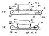
図13(A),(B)は、上記第3実施形態のプリンタ10Cの回復処理の動作過程を示す用紙幅方向に沿う縦断面図であって、図13(A)は、印刷待機状態、または、印字可能な状態であって、回復処理装置の退避状態を示し、図13(B)は、用紙搬送手段がヘッドから離間する方向に移動し、回復処理装置をプリンタヘッド下部に挿入中の状態を示す。図14(A),(B)は、同じく上記第4実施形態のプリンタ10Cの回復処理の動作過程を示す用紙幅方向から見た側面図であって、図14(A)は、印字可能な状態で回復処理装置の退避状態を示し、図14(B)は、用紙搬送手段がヘッドから離間する方向に移動し、回復処理装置をプリンタヘッド下部に挿入させた回復処理動作中の状態を示す。
【0098】
本実施形態のプリンタ10Cは、前記第2の実施形態のプリンタ10Bに対してプリンタヘッド67は上方向に移動せず、用紙搬送手段である用紙搬送系2′が搬送ベルト18′,ローラ17′と共に下方向のF2 方向に移動可能である点が異なる。なお、回復手段である回復処理装置61は、前記第3の実施形態の場合と同様にワイパーやキャップ等を有し、搬送ベルト18′の上面側にて用紙幅方向E0 方向に平行なE1 方向にスライドして挿入退避可能とし、挿入退避時の移動軌跡は、同様に階段状とする。それ以外の構成は、前述のプリンタ10と同一とする。
【0099】
以上の構成を有する本実施形態のプリンタ10Cの回復処理動作について説明すると、回復処理を行う場合、図13(A)の印字可能な状態から図13(B)に示すように用紙搬送系2′全体をF2 方向に降下させて、プリンタヘッド67と搬送ベルト18′の間の隙間を拡大する。
【0100】
上記の隙間に回復処理装置61をE1 方向にスライド移動させて挿入する。所定量だけ挿入した時点で上昇させ、ワイパーをプリンタヘッド67のインク吐出面に接触させる。それ以降、回復処理装置61のE1 方向の移動動作に伴ってワイパーにより各ヘッドユニットのインク吐出面の払拭クリーニングを行い、そして、各ヘッドユニットをキャップで覆った状態でインクをキャップ中に吐出させ、さらに、回復処理後、回復処理装置61を退避させる等の動作は、前記第3の実施形態のプリンタ10Bの動作と同一である。
【0101】
上述した第3の実施形態のプリンタ10Cによれば、前記第2の実施形態のプリンタ10Bと同様の効果を奏し、特にプリンタヘッド67を昇降させる必要がなく、プリンタヘッドおよびその周りの構造が簡単になる。
【0102】
次に、本発明の第4の実施形態のプリンタについて説明する。
図15(A),(B)は、上記第4実施形態のプリンタ10Dの回復処理の動作過程を示す用紙幅方向からみた側面図であって、図15(A)は、印字可能な状態であって、回復処理装置の退避状態を示し、図15(B)は、回復処理装置をプリンタヘッド下部に挿入させた回復処理動作中の状態を示す。
【0103】
本実施形態のプリンタ10Dは、前記第2の実施形態のプリンタ10Bに対してプリンタヘッド67は上方向に移動せず、用紙搬送手段である用紙搬送系71の搬送ベルト74がF4 方向に移動可能である点が異なる。なお、回復手段である回復処理装置61は、前記第2の実施形態の場合と同様にワイパーやキャップ等を有し、搬送ベルト74の上面側にて用紙幅方向E0 方向に平行なE1 方向(図9参照)にスライドして挿入退避可能とする。その挿入退避時の移動軌跡も同様に階段状とする。それ以外の構成は、前述のプリンタ10と同一とする。
【0104】
上記用紙搬送系71は、駆動ローラ72と、従動ローラ73と、搬送ベルト74とを有し、さらに、搬送ベルト74の用紙搬送面側である上面側におけるプリンタヘッド67の範囲の端部位置にF4 方向(下方向)に移動可能な第1のローラである一対の可動ローラ79,80と、搬送ベルト74を内面から下方向に押圧し、上下に移動可能な第2のローラである一対の可動ローラ75,77とを有している。
【0105】
なお、上記可動ローラ79,80,75,77は、それぞれ上下方向に図示しないガイド穴でガイドされており、可動ローラ75,77は、付勢バネ76,78で下方向に付勢されている。また、可動ローラ79,80は、図示しないローラ駆動機構によりF4 方向に駆動される。
【0106】
以上の構成を有する本実施形態のプリンタ10Dの回復処理動作について説明すると、回復処理を行う場合、図15(A)の印字可能な状態から図15(B)に示すように可動ローラ79,80をF4 方向に変位させ、可動ローラ79,80の間の範囲の搬送ベルト74を降下させ、プリンタヘッド67下方の隙間を拡大する。そのとき、可動ローラ75,77が反F4 方向、すなわち、プリンタヘッド67に接近する方向に付勢バネ76,78を撓ませながら移動し、搬送ベルト74の搬送方向の周長を一定に保つように張力調整がなされる。
【0107】
上記プリンタヘッド67の下方に生じた隙間に回復処理装置61を搬送方向D0 と直交するE1 方向(用紙幅方向E0 と平行な方向、図9参照)にスライド移動させて挿入する。所定量挿入した時点で上昇させ、ワイパーをプリンタヘッド67のインク吐出面に接触させる。その後、回復処理装置61の移動動作に伴うワイパーにより各ヘッドユニットのインク吐出面のクリーニングを行い、さらに、各ヘッドユニットをキャップで覆い、インクを吐出させ、さらに、回復処理後に回復処理装置61を退避させる等の一連の動作は、前記第2の実施形態のプリンタ10Bと同一である。
【0108】
上述した第4の実施形態のプリンタ10Dによれば、前記第2の実施形態のプリンタ10Bと同様の効果を奏し、特にプリンタヘッド67を昇降させる必要がなく、プリンタヘッドおよびその周りの構造が簡単になる。
【0109】
次に、本発明の第5の実施形態のプリンタについて説明する。
図16(A),(B)は、上記第5実施形態のプリンタ10Eの回復処理の動作過程を示す用紙幅方向からみた側面図であって、図16(A)は、印刷待機状態、または、印字可能な状態であって、回復処理装置の退避状態を示し、図16(B)は、回復処理装置をプリンタヘッド下部に挿入させた回復処理動作状態を示す。
【0110】
本実施形態のプリンタ10Eは、前記第2の実施形態のプリンタ10Bに対してプリンタヘッド67は上方向に移動せず、用紙搬送手段である用紙搬送系81の従動ローラ83側がD0 方向(搬送方向)に、また、搬送ベルト84の搬送面がF5 方向(上,下方向)に移動可能である点が異なる。なお、回復手段である回復処理装置61は、前記第2の実施形態の場合と同様にワイパーやキャップ等を有し、搬送ベルト84の上面側にて用紙幅方向のE0 方向に平行なE1 方向(図9参照)にスライドして挿入退避可能とする。その挿入退避時の移動軌跡も前記第2の実施形態と同一とする。それ以外の構成は、第1実施形態と同一とする。
【0111】
上記用紙搬送系81は、駆動ローラ82と、従動ローラ83と、搬送ベルト84とを有し、さらに、搬送ベルト84の用紙搬送面である上面側であって、プリンタヘッド67の範囲の端部位置にF5 方向(下方向)に移動可能な一対の可動ローラ86,87が配設されている。また、上記従動ローラ83は、搬送方向であるD0 方向にスライド移動可能に支持され、付勢バネ85により反D0 方向に付勢されている。
【0112】
以上の構成を有する本実施形態のプリンタ10Eの回復処理動作について説明すると、回復処理を行う場合、図16(A)の印字可能な状態から図16(B)に示すように可動ローラ86,87をF5 方向に変位させ、可動ローラ86,87の間の範囲の搬送ベルト84を降下させ、プリンタヘッド67の下方の隙間を拡大する。そのとき、従動ローラ83がD0 方向に付勢バネ85を撓ませながら移動して搬送ベルト84の搬送方向の周長を一定に保つように張力調整がなされる。
【0113】
上記プリンタヘッド67の下方の隙間に回復処理装置61を用紙幅方向E0 に平行なE1 方向(図9参照)にスライド移動させて挿入する。所定量挿入した時点で上昇させ、ワイパーをプリンタヘッド67のインク吐出面に接触させる。その後、回復処理装置61の移動動作に伴うワイパーによる各ヘッドユニットのインク吐出面のクリーニングを行い、さらに、各ヘッドユニットをキャップで覆ってインクを吐出させ、さらに、回復処理後、回復処理装置61を退避させる等の一連の動作は、前記第2の実施形態のプリンタ10Bの動作と同一である。
【0114】
上述した第5の実施形態のプリンタ10Eによれば、前記第2の実施形態のプリンタ10Bと同様の効果を奏し、特にプリンタヘッド67を昇降させる必要がなく、プリンタヘッドおよびその周りの構造が簡単になる。
【0115】
次に、上記第2から第5実施形態のプリンタ10B〜10Eに適用されたキャップ手段であるキャップやワイプ手段であるワイパーを含む回復処理装置に対する各変形例について説明する。
図17は、1つの変形例の回復処理装置のキャップとワイパー周りの挿入方向(E1 )に沿う縦断面図を示す。上記変形例の回復処理装置91には、その装置本体92上に複数対のキャップ93とワイパー95が配置されている。なお、上記各ワイパーは、それぞれ対応するキャップのE1 方向側に隣接して配置されている。
【0116】
上記キャップ93は、ヘッドユニットのインク吐出面上の吐出口を覆うことができるキャップ手段であり、下部に突起93aを有しており、その突起93aは、装置本体92のストッパ92aに係合し、キャップ93の上方への移動位置を規制している。また、キャップ93の両側底面部がバネ94により揺動自在に上方に付勢されている。
【0117】
したがって、上記回復処理装置91をプリンタヘッドの下方に挿入し、ヘッドユニットのインク吐出面とキャップ93の上面93bが当接したときにインク吐出面に倣ってキャップ93が傾斜するのでキャップ93の上面93bを上記インク吐出面に密着させることができる。
【0118】
上記ワイパー95は、可撓性の部材であって、弾性変形状態で摺接してインク吐出面を払拭するワイプ手段であり、装置本体92のワイパー装着部92bにスポンジ状のインク吸収体96を介して支持される。ワイパー95でインク吐出面を払拭したときの拭き取られたインクは、上記インク吸収体96に吸い取られる。
【0119】
以上のように構成された本変形例の回復処理装置91による回復処理は、前記第2実施形態における回復処理装置61による回復処理と同様にプリンタヘッドの下部にE1 方向に挿入し、階段状に移動させながらワイパー95によりヘッドユニットのインク突出面の払拭とキャップ93によりヘッドユニットのインク吐出面をキャップし、インクを吐出させる等の動作が行われる。
【0120】
本変形例の回復処理装置91によれば、キャップ93をヘッドユニットのインク吐出面に確実に密着させることができると同時にワイパー95で拭き取られインクを効率よくインク吸収体96に吸収させることができる。
【0121】
図18(A),(B)は、別の変形例の回復処理装置のキャップ部を示す図であり、図18(A)が挿入方向のE1 方向に沿った縦断面図であり、図18(B)が図18(A)のC矢視図である。
【0122】
本変形例の回復処理装置101に設けられるキャップ103は、互いに直交する2軸に揺動可能に支持されている。すなわち、キャップ103は、平行な挿入方向E1 に沿う支持軸部104aに回動可能に支持される。上記支持軸部104aが形成される支持体104は、さらに、支持軸部104aの直交する支持軸部104bを有しており、その支持軸部104bは、上記装置本体102に揺動可能に支持されている。
【0123】
したがって、キャップ103は、装置本体102に対して互いに直交する支持軸部104aと104bに支持されることからあらゆる方向に容易に傾斜可能な状態で支持されることになる。また、上記支持体104の支持軸部104aの軸端部に配設される2つのバネ105で上方に付勢され、同時に上記支持軸部104aの側方の装置本体102底面端部は、2つのバネ106で上方に付勢されている。
【0124】
上記キャップ103がヘッドユニットの下部に挿入され、そのインク吐出面に当接すると、キャップ103の端面は、上記インク吐出面に倣って傾斜し、上記バネ105,106の付勢力で密着させることができる。
【0125】
本変形例の回復処理装置101によれば、キャップ103が回復処理装置本体に対して回動し易く支持されていることからヘッドユニットのインク吐出面により確実に密着させることができる。
【0126】
図19は、さらに別の変形例の回復処理装置のキャップとワイパー周りの挿入方向(E1 )に沿う縦断面図を示す。図20(A),(B)は、上記回復処理装置の回復処理動作状態を示す断面図であり、図20(A)は、インク吐出面をワイパーによって払拭している状態、図20(B)は、ワイパーを傾倒させた状態を示す。
【0127】
上記変形例の回復処理装置111には、その装置本体112上に複数対のキャップ113とワイパー115が配置されている。なお、上記各ワイパーは、それぞれ対応するキャップのE1 方向側に隣接して配置されている。
【0128】
上記キャップ113は、ヘッドユニットのインク吐出面を覆うことができるキャップ手段であり、キャップ底面部でバネ114により上方の付勢された状態で支持されている。
【0129】
上記ワイパー115は、可撓性の部材であって、弾性変形状態で摺接してインク吐出面を払拭するワイプ手段であり、装置本体112に対して支持軸116aにより回動自在に支持され、ワイプ手段退避機構を構成するL状のワイパー支持体116にワイパー端部が固着されている。上記ワイパー支持体116は、図示しないワイパー回動駆動機構により回動駆動可能である。
【0130】
本回復処理装置111による回復処理動作も前記第2実施形態における回復処理装置61による回復処理と同様にプリンタヘッドの下部に側方からE1 方向に挿入し、階段状に移動させながら行われる。すなわち、回復処理装置111がヘッドユニットの下方挿入時に図20(A)に示すようにワイパー支持体のL状先端116bが装置本体112に当接し、直立状態にあるワイパー115の先端を変形させてヘッドユニット119のインク吐出面の払拭を行う。
【0131】
上記払拭動作が終了した時点でワイパー回動駆動機構によりワイパー支持体116を時計回りのH方向に回動駆動し、図20(B)ワイパー115を横方向に傾倒させる。そのワイパー傾倒状態で払拭を行わない状態でE2 方向(反E1 方向)に復処理装置111を退避させることができる。また、階段状のリンク形状も簡略化できる。
【0132】
本変形例の回復処理装置111によれば、ワイパー115が回動可能なワイパー支持体116で支持されていることから回復処理装置111の挿入動作時には、ワイパーによりインク吐出面の払拭を行い、退避時にはインク吐出面の払拭を行わないようにワイパーを傾倒させて移動させることができる。
【0133】
図21(A),(B)は、さらに別の変形例の回復処理装置に組み込まれるワイパー駆動機構部周りの挿入方向(E1 )に沿う縦断面図であり、図21(A)は、インク吐出面をワイパーによって払拭している状態を示し、図21(B)は、ワイパーが傾斜し、インク吐出面から離れている状態を示す。
【0134】
上記変形例の回復処理装置121においては、ヘッドユニット129に対応する複数のワイパー123がワイプ手段退避機構を構成するソレノイド125およびリンク部材を介して払拭可能な直立位置と払拭可能な位置から退避した傾斜位置に駆動される。
【0135】
上記ワイパー123は、装置本体122に対して支持軸124aを介して回動支持されるリンク部材のワイパー支持体124に装着されている。上記ワイパー支持体124は、ソレノイド125の鉄心に連結された駆動ロッド126に係合されている。ソレノイド125のオンにより鉄心が吸引されると、図21(A)に示すようにワイパー支持体124が直立してワイパー123は、インク吐出面129aを払拭可能位置に立ち上がる。ソレノイド123がオフとなると、図21(B)に示すように鉄心が解放され、駆動ロッド126が付勢バネ127の付勢力でJ方向に移動するので、ワイパー支持体124とワイパー123が傾斜し、ワイパー123は、インク吐出面129aから離れる。
【0136】
本変形例の回復処理装置121によれば、ソレノイド125のオンオフによりワイパー123をインク吐出面129aに対して払拭可能位置から離間位置に移動させることができ、インク吐出面の払拭動作を自由にコントロールすることができる。
【0137】
図22は、さらに別の変形例の回復処理装置のキャップとワイパー周りの挿入方向(E1 )に沿う縦断面の概念図を示す。
上記変形例の回復処理装置131には、その装置本体上にキャップ手段であるキャップ132と、インク吸収体134に保持された可撓性のワイプ手段であるワイパー133が配置されており、さらに、上記キャップ132とインク吸収体134には廃液管が接続され、吐出インクや吸収インクは、閉止弁135,136を経由し、廃液ポンプ137を介して廃液タンク138に流出可能である。
【0138】
以上のように構成された本変形例の回復処理装置131による回復処理は、前記第2実施形態における回復処理装置61による回復処理と同様にプリンタヘッドの下部にE1 方向に挿入し、階段状に移動させながらワイパー133によりヘッドユニットのインク吐出面の払拭とキャップ132によりヘッドユニットのインク吐出面を覆い、その状態でインクを吐出させる等の動作が行われる。
【0139】
上記ワイパー133でインク吐出面を払拭したときの拭き取られたインクは、上記インク吸収体134に吸い取られる。また、キャップ132内には、吐出インクが溜められる。上記インク吸収体134に吸収されたインクが限度に達したとき、また、キャップ132内にインクが一杯に溜まった状態になれば、閉止弁135、または、136を開放して廃液ポンプ137を駆動し、上記インクは、廃液タンク138に排出される。
【0140】
以上のように構成された本変形例の回復処理装置131によれば、キャップ132、あるいは、インク吸収体134に溜まったインクを効率よく廃液タンク138に導くことができるので、インク吸収体がインクを吸収しきれずぼた漏れ等を起こすことがない。
【0141】
図23(A)〜(D)は、各種の変形例の回復処理装置のワイプ手段であるワイパーの構造を示す図である。
図23(A)に示すワイパー構造は、最も簡単な構造のワイパーであり装置本体上に可撓性があり、かつ、インク吸収性のあるワイパー141を設けた構造である。上記ワイパー141に吸収されたインクは、廃液ポンプを介して廃液タンクに排出される。この構造によれば、構成が簡単でしかもワイパーによるインク吸収が効果的に行われる。
【0142】
図23(B)に示すワイパー構造は、ワイパー142の摺動方向(K方向)の裏面側にスポンジ状のインク吸収体143を張り合わせた構造のものであり、インク吸収体143とワイパー142とが同じ高さである。上記インク吸収体143に吸収されたインクは、廃液ポンプを介して廃液タンクに排出される。この構造によれば、ワイパー142で払拭されたインクは、直ちにインク吸収体143に吸収されていくのでクリーニング効率のよい払拭が行われる。
【0143】
図23(C)に示すワイパー構造は、ワイパー145の摺動方向(K方向)側にスポンジ状のインク吸収体146を張り合わせた構造のものであり、インク吸収体146は、ワイパー145より僅かに低くなっている。上記インク吸収体146に吸収されたインクは、廃液ポンプを介して廃液タンクに排出される。この構造によれば、ワイパー145で払拭されたインクは、そのまま下方に流され、直ちにインク吸収体146に吸収されるのでクリーニング効率のよい払拭が行われる。なお、上記インク吸収体146は、摺動方向側およびその裏面側の両側に設けるようにしてもよい。
【0144】
図23(D)に示すワイパー構造は、ワイパー153の摺動方向(K方向)の裏面側にスポンジ状のインク吸収体154を設け、さらに、摺動方向(K方向)側の中央部分にて装置本体152より突出し、ワイパー153側面に当接可能なワイパー当接片152aを設ける。さらに、上記インク吸収体154の対向位置に支持軸156に支持され、K1 方向に回動可能な吸収体押圧片155を設けている。
【0145】
以上のように構成された上記ワイパー構造では、ワイパー153で払拭され、インク吸収体154に吸収されたインクは、吸収体押圧片155を回転させることで下方に絞り出されて廃液管157に導かれる。そして、、廃液ポンプを介して廃液タンクに導かれる。このワイパー構造によると、インク吸収体154に吸収されたインクは、確実に絞り出されて、排出されるので、インク吸収体の吸収性能を一定に保て、常に良好な払拭動作が得られる。
【0146】
次に、本発明の第6の実施形態のプリンタについて説明する。
図24は、上記第6実施形態のプリンタ10Fの要部外観を示す斜視図である。図25は、上記プリンタで印刷したテストプリントサンプルを示す。
【0147】
本実施形態のプリンタ10Fは、プリンタヘッド165と、テストプリントセンサ166と、さらに、前記第1の実施形態に適用されたものと同様の用紙搬送系2と、吸引装置8と、回復処理装置9と、図示しないベルト速度・位置検出センサ等のセンサ類,駆動モータ,ヘッドコントローラ,プリント制御手段等を有してなる。
【0148】
上記プリンタヘッド165は、前記図6に示した変形例の単色ヘッドブロックである、例えば、ブラック,イエロー,マゼンダ,シアンのヘッドブロック161,162,163,164からなる。なお、このヘッドブロックは、第1の実施形態に適用したもので各色のヘッドユニットが傾斜線に沿って配置されたプリンタヘッド3を適用してもよい。
【0149】
テストプリントセンサ166は、用紙プリント幅範囲上のインク滴吐出によるベタ印刷状態のテストプリントを用紙幅方向に走査することなくドット単位で検出可能なラインセンサで構成される。なお、このテストプリンタセンサ166に代えて用紙幅方向に走査して上記ベタ印刷状態をドット単位で検出するフォトリフレクタ167を適用することも可能である。
【0150】
上述のような構成を有する本実施形態のプリンタ10Fにおいて、印字動作に先立って、あるいは、印字ドット欠け等の印字異常が認識された場合にテストプリントを行う。このテストプリントは、上記各色のヘッドブロック161,162,163,164による所定幅の色別ベタ印刷を行い、図25に示すような各色のヘッドブロックに対応した4つのプリントパターンA1 ,A2 ,A3 ,A4 が印字されたテストプリントサンプル28Bを得る。そのテストプリントサンプルを搬送ベルト18で搬送して、テストサンプルセンサ166でその印字状態を検出して、ドット欠けによる白すじの有無等の印字不良が検出される。
【0151】
例えば、上記テストプリントサンプル28Bが得られた場合、テストプリントセンサ166によりプリントパターンA4 のB1 の白すじが検出されるので、B1 に対応するヘッドブロック164の中のノズルの1つが目詰まりした印字異常状態にあることがCPUにより検知される。
【0152】
続いて、CPUの指示により上記印刷異常状態を回復させるための回復処理が実行されるが、まず、回復処理装置9を搬送ベルト18側にE1 方向に接近させ、搬送ベルト18上方であって、かつ、プリンタヘッド165下方に移動させて回復処理実行可能な状態とする。
【0153】
そこで、上記印字異常のヘッドブロックのノズルから回復処理装置9に向けてインクを吐出させてノズルの目詰まり等を回復させる。例えば、上記図25のテストプリントサンプル28Bが得られた場合には、ヘッドブロック164のノズルよりインクを吐出させて回復処理を行う。
【0154】
その後、回復処理装置9を反E1 に移動させて搬送ベルト18の側方に退出させ、印字可能状態にセットする。なお、上記回復処理を行っても印字異常が解消されない場合には、前記図6、または、図4に示した該当するヘッドユニットをヘッド支持基板49、あるいは、ヘッド支持基板41,42等から抜き取り、良品のヘッドブロックと簡単に交換できる。
【0155】
上述した第6実施形態のプリンタ10Fによると、プリントヘッド165の印字不良状態を検出し、該当するヘッドブロックのみからインクを吐出させて印字機能の回復が自動的に行われ、使い勝手のよいプリンタを提供することができる。
【0156】
次に、上記第6の実施形態のプリンタ10Fに適用されるプリンタヘッドを構成するヘッドブロックに対する変形例について説明する。
図26は、上記変形例のヘッドブロックの斜視図である。この変形例のヘッドブロック181は、内部に複数のインク吐出口を有するヘッドブロックであり、プリンタヘッド本体(図示せず)に対して後述するアクチュエータ191,192、および、193を介してX軸方向とY軸方向に微小距離だけ移動可能な状態で支持されている。
【0157】
なお、上記X軸方向は、用紙幅方向(E0 方向)に、上記Y軸方向は、用紙搬送方向(D0 方向)の逆方向に一致する。上記X,Y軸と直交する方向(上下方向)をZ軸とする。また、Z軸回りの回動角をθ1 とし、X軸回りの回動角をθ2 とし、Y軸回りの回動角をθ3 とする。
【0158】
上記アクチュエータ191,192は、圧電素子で構成され、ヘッドブロック本体のX軸方向端部のY軸方向の壁面とプリンタ本体間に介在して取り付けられる。また、アクチュエータ193も圧電素子で構成され、ヘッドブロック本体のX軸方向の壁面とプリンタ本体間に介在して取り付けられる。
【0159】
上記アクチュエータ191,192,193は、プリンタ組み立て時、プリンタヘッド本体に対するヘッドブロックのノズル位置、または、ヘッドブロックの姿勢に誤差がある場合、誤差量データをメモリに記憶しておき、印刷時にCPUの制御のもとでアクチュエータドライバを介して上記アクチュエータが所定量駆動され、上記ヘッドブロックの取り付け壁面位置を上記誤差量データに対応した距離だけ微小距離変位させ、上記ノズル位置、または、ヘッドブロックの姿勢の誤差を修正する。
【0160】
図27は、ヘッドブロック181のZ軸方向がZ′軸方向に傾いているとき、すなわち、Y軸回りに角度θ3 だけ傾斜しているときのインク滴吐出状態を示す。このような状態では、ノズル181aによるインク吐出方向が角度θ3 だけ傾斜することから、まず、用紙28上でのインク滴の到達位置が上記の傾斜でインク吐出方向が傾くことで、X軸方向にずれる。同時にヘッドブロック181のX軸に沿う位置によってインク吐出面と用紙28の離間距離Z1 が変化することからインク滴到達タイミングが変化してY軸方向にもずれる。
【0161】
上記X軸方向のずれは、実用的に無視できるので特に補正する必要はないが、上記Y軸方向のずれは、搬送速度にも関連し、補正する必要がある。その補正は、アクチュエータ191,192を駆動することによりヘッドブロック181をθ1 方向に回動させてインク滴の用紙到達タイミングをずらし補正することができる。そのときのヘッドの補正状態は、例えば、後述する図28(A)に示される。
【0162】
図28(A),(B)は、ヘッドブロックに組み込まれるヘッドユニットのノズル位置のずれ状態を示す模式図である。図28(A)は、ヘッドブロック181がZ軸回りに角度θ1 だけ傾いている場合を示している。この場合、アクチュエータ191,192を駆動し、ヘッドブロック181を角度θ1 だけ逆方向に回動させることで上記ずれを補正する。
【0163】
また、図28(B)は、基準とするヘッドブロック181に対してヘッドブロック182がX軸方向にずれている状態を示している。すなわち、ヘッドブロック182のノズル182aの相対位置δ02は、ヘッドブロック181のノズル181aの間隔2δP の1/2の位置にある必要がある。それがずれている場合には、アクチュエータ193によりX軸方向にずれ分だけヘッドブロック182を変位させて位置修正を行うことができる。
【0164】
次に、上記第6の実施形態のプリンタ10Fのプリンタヘッドを構成するヘッドブロックの位置,姿勢ずれをインク吐出タイミング制御により修正するタイミング制御方法を採用した変形例について説明する。
図29(A),(B),(C)は、上記変形例の制御方法を適用するヘッドブロックの側面図であって、各ヘッドブロックの位置,姿勢でのインク滴吐出状態を示す。
【0165】
図29(A)は、ヘッドブロック186が基準となるヘッドブロック185に対してZ軸方向(上下方向)に寸法ΔZだけずれているときのインク滴吐出状態を示している。この場合、ヘッドブロック186のインク吐出面186bと用紙28の表面間の離間距離がΔZだけ長くなっているのでヘッドブロック186から吐出されたインク滴202は、基準となるヘッドブロック185で吐出されるインク滴201よりも距離ΔZに相当する時間だけ遅く用紙表面に到達する。
【0166】
したがって、基準となるインク滴201による印字ドット位置とインク滴202による印字ドット位置は、本来の相対位置に対して搬送方向にずれた位置、すなわち、反D0 方向にずれた位置になる。
【0167】
上記のずれを補正するためには、搬送速度を考慮し、上記ヘッドブロック182のインク吐出タイミングを距離ΔZに相当する時間だけ早く吐出するように吐出タイミングをCPUによりタイミング制御することによってずれのない印字が可能になる。
【0168】
図29(B)は、ヘッドブロック185がZ軸方向(上下方向)傾いているとき、すなわち、X軸回りに回動角θ2 だけ傾斜しているときのインク滴吐出状態を示している。この場合、上記傾斜したヘッドブロック185のノズルから吐出されるインク滴204の用紙28上での到達位置は、傾斜のないヘッドブロックのインク滴203の到達位置より距離δ03だけD0 方向にずれて印字される。
【0169】
上記のずれを補正するためには、搬送速度を考慮し、上記距離δ03に相当する時間だけ吐出タイミングを遅らせるようにCPUによりタイミング制御することで上記傾斜によるずれ補正が可能である。
【0170】
図29(C)は、ヘッドブロック185が−Y軸方向に平行に距離δ04だけずれているときのインク滴吐出状態を示している。この場合、上記ヘッドブロック185のノズルから吐出されるインク滴206の用紙28上の到達位置は、ずれのないヘッドブロックから吐出されるインク滴205の到達位置に対して当然ながら距離δ04だけD0 方向にずれることになる。
【0171】
したがって、上記のずれを補正するためには、搬送速度を考慮し、上記距離δ04に相当するだけ吐出タイミングを遅らせるようにCPUによりタイミング制御することで上記平行移動によるずれ補正が可能である。
【0172】
【発明の効果】
本発明によれば、複数のノズルよりインク滴を吐出してプリントを行うプリンタにおいて、インク吐出面の回復処理が容易であり、その回復手段の構造も簡単であって、プリンタの大型化が避けられ、コストの低価格化も可能であり、また、調整や維持,管理等も容易であるプリンタを提供することができる。
【図面の簡単な説明】
【図1】本発明のプリンタのシステム構成図。
【図2】上記図1のプリンタの印刷部周りの概要を示す縦断面図。
【図3】上記図1のプリンタに適用される用紙搬送系の構造を示す斜視図。
【図4】上記図1のプリンタに適用されるプリンタヘッドの分解斜視図。
【図5】上記図1のプリンタに適用されるプリンタヘッドを構成するヘッドユニットのノズル配置を示すインク吐出面側(図4のA側)からみた拡大図。
【図6】上記図1のプリンタに適用されるプリンタヘッド(ヘッドブロック)の変形例としてのB(黒)ヘッドブロックの斜視図。
【図7】本発明の第1の実施形態のプリンタの要部を示す斜視図であり、回復処理装置の退避状態を示す。
【図8】上記第1の実施形態のプリンタの要部を示す斜視図であり、回復処理装置をプリンタヘッド下部に挿入した状態を示す。
【図9】本発明の第2実施形態のプリンタの要部を示す斜視図であり、回復処理装置が退避した状態を示す。
【図10】上記第2の実施形態のプリンタの各動作状態での要部の断面図であって、図9のB−B断面を示し、図10(A)は、印刷待機状態、または、印字可能状態であって、回復処理装置が退避した状態を示し、図10(B)〜(E)は、回復処理の各動作状態を示す。
【図11】上記第2の実施形態のプリンタにおける回復処理装置に適用される回復処理装置本体のガイド板の要部を示す側面図。
【図12】上記第2の実施形態のプリンタにおける回復処理装置に適用される回復処理装置本体のガイド板によるガイド動作過程を示す図。
【図13】本発明の第3の実施形態のプリンタの回復処理動作過程を示す用紙幅方向に沿う縦断面図であって、図13(A)は、印刷待機状態、または、印字可能状態であって、回復処理装置が退避した状態を示し、図13(B)は、回復処理動作状態を示す。
【図14】上記第3の実施形態のプリンタの回復処理動作過程を示す用紙幅方向から見た側面図であって、図14(A)は、印刷待機状態、または、印字可能状態であって、回復処理装置が退避した状態を示し、図14(B)は、回復処理動作状態を示す。
【図15】上記第4の実施形態のプリンタの回復処理動作過程を示す用紙幅方向から見た側面図であって、図15(A)は、印刷待機状態、または、印字可能状態であって、回復処理装置が退避した状態を示し、図15(B)は、回復処理動作状態を示す。
【図16】本発明の第5の実施形態のプリンタの回復処理動作過程を示す用紙幅方向から見た側面図であって、図16(A)は、印刷待機状態、または、印字可能状態であって、回復処理装置が退避した状態を示し、図16(B)は、回復処理動作状態を示す。
【図17】上記第2〜第5の実施形態のプリンタにおける回復処理装置の変形例のキャップとワイパーの挿入方向に沿う縦断面図。
【図18】上記第2〜第5の実施形態のプリンタにおける回復処理装置の別の変形例のキャップを示す図であって、図18(A)は縦断面図であり、図18(B)は図18(A)のC矢視図である。
【図19】上記第2〜第5の実施形態のプリンタにおける回復処理装置のさらに別の変形例のキャップとワイパーの挿入方向に沿う縦断面図。
【図20】上記図19の変形例のキャップとワイパーの回復処理動作状態を示す断面図であって、図20(A)は、ワイパー払拭動作状態を示し、図20(B)は、ワイパーを傾倒させた状態を示す。
【図21】上記第2〜第5の実施形態のプリンタの回復処理装置に組み込まれるさらに別の変形例のワイパー駆動機構部周りの挿入方向に沿う縦断面図であり、図21(A)は、インク吐出面をワイパーによって払拭している状態を示し、図21(B)は、ワイパーが傾斜し、インク吐出面から離れている状態を示す。
【図22】上記第2〜第5の実施形態のプリンタにおける回復処理装置のさらに別の変形例のキャップとワイパーの挿入方向に沿う縦断面の概念図。
【図23】上記第2〜第5の実施形態のプリンタにおける回復処理装置のさらに別の変形例のワイパーの挿入方向に沿う縦断面図であって、図23(A)〜(D)は、上記変形例の各種形状のワイパーを示す。
【図24】本発明の第6の実施形態のプリンタの要部外観を示す斜視図。
【図25】上記第6の実施形態のプリンタにより印刷されたテストプリントサンプルを示す図。
【図26】上記第6の実施形態のプリンタのプリンタヘッドを構成するヘッドブロックの変形例の斜視図。
【図27】上記図26の変形例のヘッドブロックがY軸周りに傾斜しているときのインク滴吐出状態を示す側面図。
【図28】上記図26の変形例のヘッドブロックのノズル位置のずれ状態を示す模式図であって、図28(A)は、上記ノズルがZ軸周りに傾斜した状態を示し、図28(B)は、上記ノズルがX軸方向にずれている状態を示す。
【図29】上記第6の実施形態のプリンタに対してヘッドブロックからのインク吐出タイミング制御の変形例を適用したプリンタのインク滴吐出状態を示す用紙幅方向から見た側面図であって、図29(A),(B),(C)は、それぞれヘッドブロックの位置、または、姿勢にずれのあるときのインク滴吐出状態を示す。
【符号の説明】
1 ……CPU(プリンタ制御手段)
2,2′……用紙搬送系(用紙搬送手段)
3,67,165……プリンタヘッド
9,61,91,101,111,121,131,151……回復処理装置(回復手段)
28 ……用紙(印刷用紙)
39,119a,129a,186a……インク吐出面
54a,54b,55a,55b,63a,63b,63c,……キャップ(キャップ手段)
65a,65b,65c,95,115,123,133,141,142,145,153……ワイパー(ワイプ手段)
75,77……第2のローラ
79,80,86,87……第1のローラ
96,134,143,146,154……インク吸収体
124 ……ワイパー支持体(リンク機構,ワイプ手段退避機構)
125 ……ソレノイド(ワイプ手段退避機構)[0001]
BACKGROUND OF THE INVENTION
The present invention relates to a structure of a printer that performs printing by ejecting ink droplets from a plurality of nozzles.
[0002]
[Prior art]
As a conventional consumer printer, a so-called inkjet printer that performs printing by ejecting minute ink droplets from a plurality of nozzles scans the head in the main scanning direction (paper width direction) and performs head scanning. The type is common. A printer head applied to this head scanning type printer has a plurality of nozzles along the same direction as the sub-scanning direction (paper feeding direction) or an inclined direction, and scans the printer head in the main scanning direction. Print the full width of the paper.
[0003]
Therefore, a scanning drive mechanism in the main scanning direction of the printer head and a paper feed mechanism are required as the feed drive mechanism, which complicates the drive mechanism and limits the increase in printing speed.
[0004]
Therefore, a full-line inkjet printer that does not require driving of the printer head in the main scanning direction can be considered as one that can simplify the drive mechanism and increase the printing speed. This full-line inkjet printer has a full-line head having a print width corresponding to the paper width, and performs printing in one pass. Since one line is simultaneously printed in the width direction of the paper, no head scanning is required, and the paper is sequentially printed line by line while being conveyed in one direction intermittently or continuously.
[0005]
The above full-line inkjet printer has a printer head that prints the paper width in one pass, and the ink ejection surface for keeping the ink ejection surface of each nozzle of a large number of channels always in a good state without clogging. It is necessary to incorporate a recovery device.
[0006]
[Problems to be solved by the invention]
However, in the conventional full-line print type ink jet printer, since the number of nozzles is extremely large, the space occupied by the ejection surface recovery device is increased, and it is complicated to reliably clean the entire area of the ink ejection surface. In view of the necessity of adopting a simple driving method, an increase in size of the printer apparatus is inevitable, and it is inevitable that the price is disadvantageous.
[0007]
Moreover, in the conventional full-line print type ink jet printer, it is necessary to accurately arrange the position of each nozzle. However, when the printer head is divided into several blocks, the position adjustment becomes troublesome, Maintenance and management become difficult and commercialization becomes difficult.
[0008]
The present invention has been made to solve the above-described problems, and in a printer that performs printing by ejecting ink droplets from a plurality of nozzles, the recovery process of the ink ejection surface is easy, and the recovery means. It is an object of the present invention to provide a printer that is simple in structure, avoids upsizing of the printer, can be reduced in cost, and is easy to adjust, maintain, and manage.
[0009]
[Means for Solving the Problems]
According to a first aspect of the present invention, there is provided a printer that performs printing by ejecting ink droplets from a plurality of nozzles, a full-line printer head having an ink ejection surface on which the plurality of nozzles are disposed, and printing paper. And a recovery belt that recovers the discharge function of the nozzles of the print head, and a recovery means that recovers the discharge function of the nozzles of the print head. A belt moving means for depressing at least a portion of the transport belt facing the ink discharge surface and expanding a gap between the ink discharge surface and the transport belt more than at the time of printing. The recovery means is moved to the gap formed by the belt moving means, and the recovery means is Moving means for facing the Toheddo, the And the belt moving means includes a pair of rollers disposed on the conveyance surface side of the conveyance belt that holds the printing paper, and the pair of rollers is separated from the ink ejection surface of the printer head. By moving it, the gap between the ink ejection surface and the conveyor belt can be made larger than when printing. And features.
[0010]
According to a second aspect of the present invention, there is provided a printer. In a printer that performs printing by ejecting ink droplets from a plurality of nozzles, a full-line printer head having an ink ejection surface on which the plurality of nozzles are disposed, a printing paper, and the printing paper When carrying out the recovery process of the print head by the recovery means that recovers the discharge function of the nozzle of the print head, the transfer belt that is stretched over at least two rollers that are transferred so as to face the discharge surface A belt moving unit that pushes down at least a portion of the transport belt that faces the ink ejection surface to enlarge a gap between the ink ejection surface and the transport belt as compared to printing, and the gap formed by the belt movement unit. Moving the recovery means, and moving the recovery means to face the print head And the belt moving means is disposed on a pair of first rollers disposed on a conveying surface side of the conveying belt that holds the printing paper, and on an inner surface of the conveying belt opposite to the conveying surface. A pair of second rollers, and when the gap between the ink ejection surface and the transport belt is enlarged more than during printing, the first roller is moved away from the printer head in the direction of separating the first roller. 2 rollers can be moved in the direction approaching the printer head. And features.
[0011]
According to a third aspect of the present invention, there is provided a printer. In a printer that performs printing by ejecting ink droplets from a plurality of nozzles, a full-line printer head having an ink ejection surface on which the plurality of nozzles are disposed, a printing paper, and the printing paper When carrying out the recovery process of the print head by the recovery means that recovers the discharge function of the nozzle of the print head, the transfer belt that is stretched over at least two rollers that are transferred so as to face the discharge surface A belt moving unit that pushes down at least a portion of the transport belt that faces the ink ejection surface to enlarge a gap between the ink ejection surface and the transport belt as compared to printing, and the gap formed by the belt movement unit. Moving the recovery means, and moving the recovery means to face the print head And the belt moving means includes a pair of rollers disposed on the conveyance surface side of the conveyance belt that holds the printing paper, and the gap between the ink ejection surface and the conveyance belt is larger than that during printing. When enlarging, the pair of rollers are moved away from the printer head, and one of the two rollers over which the conveyor belt is stretched is moved closer to the other roller. And features.
[0012]
A printer according to claim 4 of the present invention is Item 1 to
[0013]
A printer according to
[0014]
A printer according to
[0015]
A printer according to
[0017]
Claim of the
A sheet conveying unit that has at least two rollers and an endless conveying belt that is stretched between the two rollers, and is disposed to face the ink ejection surface of the printer head, and conveys printing paper; Recovery means for recovering the ejection function of the nozzles of the printer head,
When carrying out the recovery process of the print head by the recovery means, the paper transport means sets one of the two rollers to the other roller so as to form a space where the recovery means can face the print head. It is characterized by sliding in the approaching direction and moving the conveyor belt downward.
[0035]
DETAILED DESCRIPTION OF THE INVENTION
Hereinafter, embodiments of the present invention will be described with reference to the drawings.
FIG. 1 is a basic system configuration diagram of a
[0036]
The
[0037]
The
[0038]
The
[0039]
The
[0040]
The
[0041]
The
[0042]
The detailed structure of the
[0043]
The
[0044]
The
[0045]
The
[0046]
The
[0047]
The
[0048]
The
[0049]
The
[0050]
The
[0051]
In the assembled state as the
[0052]
FIG. 5 is an enlarged view of the three head units that are part of the head block as viewed from the
[0053]
On the
[0054]
The
[0055]
The
[0056]
The printing operation in the
[0057]
Thereafter, the
[0058]
When it is detected by the belt speed /
[0059]
If the speed of the
[0060]
Further, when the inclination (skew) of the holding position of the
[0061]
After the printing is performed, after the ink is dried by the
[0062]
As described with reference to the nozzle arrangement in FIG. 5, the
[0063]
As described above, according to the
[0064]
In addition, since the
[0065]
In the
[0066]
Since the
[0067]
Since the
[0068]
The above-mentioned ink droplet ejection correction control technique for correcting the print density due to the nozzle overlap described above is described in detail in Japanese Patent Application No. 10-353253 filed earlier by the present applicant. .
[0069]
In the
[0070]
FIG. 6 is a perspective view of a B (black)
[0071]
The relative arrangement relationship of the
[0072]
Next, the printer according to the first embodiment of the present invention will be described.
7 and 8 are perspective views showing the main part of the printer 10A of the first embodiment, and FIG. 7 shows a state in which the recovery processing device is retracted during printing standby or printing operation. FIG. 8 shows a recovery processing execution state in which the recovery processing device is inserted under the head.
[0073]
The printer 10A according to the present embodiment is capable of moving in the upper F1 direction in which the
[0074]
The
[0075]
When the printer 10A is in a printing operation state, the
[0076]
When the
[0077]
According to the printer 10A of the present embodiment, when the recovery process is performed, all the ink ejection surfaces of the
[0078]
Next, a printer according to a second embodiment of the present invention will be described.
FIG. 9 is a perspective view showing a main part of the printer 10B of the second embodiment, and shows a state in which the recovery processing device is retracted. FIGS. 10A to 10E are cross-sectional views taken along line BB in FIG. 9 and show the operation process of the recovery process. FIG. 10A shows a print standby state or a printable state. It shows a state where the recovery processing apparatus before the recovery processing is evacuated. FIGS. 10B to 10E show the operation states of the recovery process. FIG. 11 is a side view showing the main part of the guide plate of the recovery processing apparatus main body applied to the recovery processing apparatus, and FIG. 12 is an enlarged view showing the operation process of the guide pin on the cam groove of the guide plate. is there.
[0079]
The printer 10B of the present embodiment is such that the
[0080]
A
[0081]
The plurality of recovery units include
[0082]
The
[0083]
The
[0084]
The guide groove 69c1 forms a cam groove region Sb that holds the guide pin 66a at a predetermined height. The height of the
[0085]
The guide groove 69c2 forms a cam groove region Sc that holds the guide pin 66a at a predetermined elevated height higher than the guide groove 69c1. The height of the
The cam groove into which the
[0086]
The recovery processing operation of the printer 10B of the present embodiment having the above configuration will be described with reference to FIGS.
The
[0087]
When the apparatus
[0088]
When executing the recovery process, first, the
[0089]
Accordingly, when the apparatus
[0090]
When the apparatus
[0091]
Further, when the apparatus
[0092]
Thereafter, when the apparatus
[0093]
Subsequently, the
[0094]
In the above embodiment, the
[0095]
According to the printer 10B of the second embodiment described above, when performing the recovery process, only the vertical movement of the printer head and the operation of inserting the
[0096]
In addition, the ink discharge surface cleaning of the plurality of head units by the wiper can be efficiently performed by the insertion operation of the
[0097]
Next, a printer according to a third embodiment of the present invention will be described.
FIGS. 13A and 13B are longitudinal sectional views along the paper width direction showing the operation process of the recovery process of the printer 10C of the third embodiment, and FIG. Alternatively, FIG. 13B shows a retractable state of the recovery processing apparatus in a printable state, and FIG. 13B shows the state in which the paper transport means moves away from the head and the recovery processing apparatus is being inserted under the printer head. Indicates the state. FIGS. 14A and 14B are side views showing the operation process of the recovery process of the printer 10C of the fourth embodiment, viewed from the paper width direction, and FIG. 14A is printable. FIG. 14B shows a state during the recovery processing operation in which the sheet conveying means moves in a direction away from the head and the recovery processing device is inserted below the printer head. .
[0098]
In the printer 10C according to the present embodiment, the
[0099]
The recovery processing operation of the printer 10C according to the present embodiment having the above configuration will be described. When the recovery processing is performed, the paper conveyance system 2 'as shown in FIG. 13B from the printable state of FIG. The whole is lowered in the F2 direction, and the gap between the
[0100]
The
[0101]
According to the printer 10C of the third embodiment described above, the same effects as those of the printer 10B of the second embodiment can be obtained, and it is not particularly necessary to raise and lower the
[0102]
Next, a printer according to a fourth embodiment of the present invention will be described.
15A and 15B are side views showing the operation process of the recovery process of the printer 10D of the fourth embodiment as seen from the paper width direction. FIG. 15A shows a printable state. FIG. 15B shows a state during the recovery processing operation in which the recovery processing device is inserted below the printer head.
[0103]
In the printer 10D of this embodiment, the
[0104]
The
[0105]
The
[0106]
The recovery processing operation of the printer 10D of the present embodiment having the above configuration will be described. When performing the recovery processing, the
[0107]
The
[0108]
According to the printer 10D of the fourth embodiment described above, the same effects as those of the printer 10B of the second embodiment can be obtained, and it is not particularly necessary to raise and lower the
[0109]
Next, a printer according to a fifth embodiment of the invention will be described.
FIGS. 16A and 16B are side views showing the operation process of the recovery process of the
[0110]
In the
[0111]
The
[0112]
The recovery processing operation of the
[0113]
The
[0114]
According to the
[0115]
Next, modifications of the recovery processing apparatus including a cap as a cap unit and a wiper as a wipe unit applied to the printers 10B to 10E according to the second to fifth embodiments will be described.
FIG. 17 shows a longitudinal sectional view along the insertion direction (E1) around the cap and wiper of the recovery processing device of one modification. A plurality of pairs of
[0116]
The
[0117]
Therefore, when the
[0118]
The
[0119]
The recovery processing by the
[0120]
According to the
[0121]
18 (A) and 18 (B) are views showing a cap portion of a recovery processing apparatus according to another modification, and FIG. 18 (A) is a longitudinal sectional view along the E1 direction of the insertion direction. (B) is a C arrow view of FIG. 18 (A).
[0122]
The
[0123]
Therefore, since the
[0124]
When the
[0125]
According to the
[0126]
FIG. 19 shows a longitudinal sectional view along the insertion direction (E1) around the cap and wiper of a recovery processing apparatus of still another modification. 20A and 20B are cross-sectional views showing the recovery processing operation state of the recovery processing apparatus. FIG. 20A is a state in which the ink discharge surface is wiped with a wiper, and FIG. ) Shows a state where the wiper is tilted.
[0127]
A plurality of pairs of
[0128]
The
[0129]
The
[0130]
Similarly to the recovery processing by the
[0131]
When the wiping operation is completed, the
[0132]
According to the
[0133]
FIGS. 21A and 21B are longitudinal sectional views along the insertion direction (E1) around the wiper drive mechanism portion incorporated in the recovery processing apparatus of still another modification. FIG. FIG. 21B shows a state where the ejection surface is wiped by the wiper, and FIG. 21B shows a state where the wiper is inclined and separated from the ink ejection surface.
[0134]
In the
[0135]
The
[0136]
According to the
[0137]
FIG. 22 shows a conceptual diagram of a longitudinal section along the insertion direction (E1) around the cap and wiper of a recovery processing apparatus of still another modification.
In the
[0138]
The recovery processing by the
[0139]
The ink wiped off when the ink discharge surface is wiped by the
[0140]
According to the
[0141]
FIGS. 23A to 23D are diagrams showing the structure of a wiper that is a wiping means of a recovery processing apparatus according to various modifications.
The wiper structure shown in FIG. 23A is a wiper having the simplest structure, and has a structure in which a
[0142]
The wiper structure shown in FIG. 23B has a structure in which a sponge-
[0143]
The wiper structure shown in FIG. 23C is a structure in which a sponge-
[0144]
In the wiper structure shown in FIG. 23D, a sponge-
[0145]
In the wiper structure configured as described above, the ink wiped by the
[0146]
Next, a printer according to a sixth embodiment of the present invention will be described.
FIG. 24 is a perspective view showing the external appearance of the main part of the printer 10F of the sixth embodiment. FIG. 25 shows a test print sample printed by the printer.
[0147]
The printer 10F according to the present embodiment includes a
[0148]
The
[0149]
The
[0150]
In the printer 10F of the present embodiment having the above-described configuration, a test print is performed prior to a printing operation or when a printing abnormality such as a missing printing dot is recognized. In this test print, solid printing for each color with a predetermined width is performed by the head blocks 161, 162, 163, and 164 of each color, and four print patterns A1, A2, A3 corresponding to the head blocks of each color as shown in FIG. , A4 is printed on the test print sample 28B. The test print sample is transported by the
[0151]
For example, when the test print sample 28B is obtained, the
[0152]
Subsequently, a recovery process for recovering the above-described abnormal printing state is executed according to an instruction from the CPU. First, the
[0153]
Therefore, ink is ejected from the nozzle of the head block having the printing abnormality toward the
[0154]
Thereafter, the
[0155]
According to the printer 10F of the sixth embodiment described above, a printing failure state of the
[0156]
Next, a modified example of the head block constituting the printer head applied to the printer 10F of the sixth embodiment will be described.
FIG. 26 is a perspective view of a head block according to the modified example. The
[0157]
The X-axis direction coincides with the paper width direction (E0 direction), and the Y-axis direction coincides with the reverse direction of the paper transport direction (D0 direction). A direction (vertical direction) orthogonal to the X and Y axes is defined as a Z axis. A rotation angle around the Z axis is θ1, a rotation angle around the X axis is θ2, and a rotation angle around the Y axis is θ3.
[0158]
The
[0159]
The
[0160]
FIG. 27 shows the ink droplet ejection state when the Z-axis direction of the
[0161]
The deviation in the X-axis direction is practically negligible and need not be corrected. However, the deviation in the Y-axis direction is related to the conveyance speed and needs to be corrected. The correction can be performed by driving the
[0162]
FIGS. 28A and 28B are schematic views showing the nozzle position shift state of the head unit incorporated in the head block. FIG. 28A shows a case where the
[0163]
FIG. 28B shows a state in which the
[0164]
Next, a modified example employing a timing control method for correcting the position and orientation deviation of the head block constituting the printer head of the printer 10F of the sixth embodiment by ink ejection timing control will be described.
FIGS. 29A, 29B, and 29C are side views of head blocks to which the control method of the above modification is applied, and show ink droplet ejection states at the positions and postures of the head blocks.
[0165]
FIG. 29A shows an ink droplet ejection state when the
[0166]
Therefore, the print dot position by the ink droplet 201 and the print dot position by the
[0167]
In order to correct the above-described deviation, in consideration of the conveyance speed, the ejection timing is controlled by the CPU so that the ink ejection timing of the
[0168]
FIG. 29B shows an ink droplet ejection state when the
[0169]
In order to correct the deviation, the deviation correction by the inclination can be performed by controlling the timing by the CPU so as to delay the discharge timing by a time corresponding to the distance δ03 in consideration of the conveyance speed.
[0170]
FIG. 29C shows an ink droplet ejection state when the
[0171]
Therefore, in order to correct the deviation, the deviation correction by the parallel movement can be performed by controlling the timing by the CPU so that the ejection timing is delayed by the distance δ04 in consideration of the conveyance speed.
[0172]
【The invention's effect】
According to the present invention, in a printer that performs printing by discharging ink droplets from a plurality of nozzles, the recovery process of the ink discharge surface is easy, the structure of the recovery means is simple, and the enlargement of the printer is avoided. Thus, it is possible to provide a printer that can be reduced in cost and that can be easily adjusted, maintained, and managed.
[Brief description of the drawings]
FIG. 1 is a system configuration diagram of a printer of the present invention.
FIG. 2 is a longitudinal sectional view showing an outline around a printing unit of the printer shown in FIG.
3 is a perspective view showing the structure of a paper transport system applied to the printer shown in FIG.
4 is an exploded perspective view of a printer head applied to the printer of FIG.
5 is an enlarged view from the ink ejection surface side (A side in FIG. 4) showing a nozzle arrangement of a head unit constituting a printer head applied to the printer in FIG. 1;
6 is a perspective view of a B (black) head block as a modified example of a printer head (head block) applied to the printer of FIG. 1; FIG.
FIG. 7 is a perspective view illustrating a main part of the printer according to the first embodiment of the present invention, showing a retracted state of the recovery processing apparatus.
FIG. 8 is a perspective view showing a main part of the printer of the first embodiment, showing a state in which a recovery processing device is inserted in the lower part of the printer head.
FIG. 9 is a perspective view illustrating a main part of a printer according to a second embodiment of the present invention, showing a state in which a recovery processing apparatus is retracted.
FIG. 10 is a cross-sectional view of a main part in each operation state of the printer of the second embodiment, showing a cross section taken along the line BB of FIG. 9, and FIG. FIG. 10B shows a state in which printing is possible and the recovery processing device has been retracted, and FIGS. 10B to 10E show each operation state of the recovery processing.
FIG. 11 is a side view showing a main part of a guide plate of a recovery processing apparatus main body applied to the recovery processing apparatus in the printer of the second embodiment.
FIG. 12 is a diagram showing a guide operation process by a guide plate of a recovery processing apparatus main body applied to the recovery processing apparatus in the printer of the second embodiment.
FIG. 13 is a longitudinal sectional view along the paper width direction showing a recovery process operation process of a printer according to a third embodiment of the present invention, and FIG. 13A shows a print standby state or a printable state; FIG. 13B shows the state of the recovery processing operation.
FIG. 14 is a side view showing the recovery process operation process of the printer of the third embodiment viewed from the paper width direction, and FIG. 14A shows a print standby state or a printable state; FIG. 14B shows the recovery processing operation state.
FIG. 15 is a side view seen from the paper width direction showing the recovery processing operation process of the printer of the fourth embodiment, and FIG. 15A shows a print standby state or a printable state; FIG. 15B shows the recovery processing operation state.
FIG. 16 is a side view of a printer according to a fifth embodiment of the present invention, illustrating a recovery process operation process as viewed from the paper width direction. FIG. 16A illustrates a print standby state or a printable state. FIG. 16B shows the state of the recovery processing operation.
FIG. 17 is a longitudinal sectional view along the insertion direction of a cap and a wiper of a modification of the recovery processing device in the printer of the second to fifth embodiments.
18 is a view showing a cap of another modification of the recovery processing apparatus in the printer of the second to fifth embodiments, and FIG. 18 (A) is a longitudinal sectional view and FIG. 18 (B). FIG. 19 is a view as seen from the direction of arrow C in FIG.
FIG. 19 is a longitudinal sectional view taken along the insertion direction of a cap and a wiper of still another modification of the recovery processing device in the printer of the second to fifth embodiments.
FIG. 20 is a cross-sectional view showing a recovery operation operation state of the cap and wiper according to the modified example of FIG. 19, in which FIG. 20A shows a wiper wiping operation state, and FIG. Indicates the tilted state.
FIG. 21 is a longitudinal sectional view taken along the insertion direction around a wiper drive mechanism portion of still another modified example incorporated in the printer recovery processing apparatus of the second to fifth embodiments, and FIG. FIG. 21B shows a state where the ink discharge surface is wiped by the wiper, and FIG. 21B shows a state where the wiper is inclined and separated from the ink discharge surface.
FIG. 22 is a conceptual diagram of a longitudinal section along the insertion direction of a cap and a wiper of still another modified example of the recovery processing device in the printer of the second to fifth embodiments.
FIG. 23 is a longitudinal sectional view along the insertion direction of a wiper of still another modified example of the recovery processing device in the printer of the second to fifth embodiments, and FIGS. 23 (A) to (D) are The wiper of the various shapes of the said modification is shown.
FIG. 24 is a perspective view showing the external appearance of the main part of a printer according to a sixth embodiment of the present invention.
FIG. 25 is a diagram showing a test print sample printed by the printer of the sixth embodiment.
FIG. 26 is a perspective view of a modified example of the head block constituting the printer head of the printer of the sixth embodiment.
FIG. 27 is a side view showing an ink droplet ejection state when the head block of the modified example of FIG. 26 is tilted around the Y axis.
FIG. 28 is a schematic diagram showing a shift state of the nozzle position of the head block of the modified example of FIG. 26, and FIG. 28 (A) shows a state in which the nozzle is inclined around the Z axis. B) shows a state where the nozzle is displaced in the X-axis direction.
FIG. 29 is a side view showing the ink droplet ejection state of the printer in which a modified example of the ink ejection timing control from the head block is applied to the printer of the sixth embodiment, as viewed from the paper width direction. 29 (A), (B), and (C) respectively show ink droplet ejection states when there is a deviation in the position or posture of the head block.
[Explanation of symbols]
1 …… CPU (printer control means)
2, 2 '... Paper transport system (paper transport means)
3,67,165 …… Printer head
9, 61, 91, 101, 111, 121, 131, 151... Recovery processing device (recovery means)
28 …… Paper (printing paper)
39, 119a, 129a, 186a ... ink ejection surface
54a, 54b, 55a, 55b, 63a, 63b, 63c, ... cap (cap means)
65a, 65b, 65c, 95, 115, 123, 133, 141, 142, 145, 153... Wiper (wipe means)
75, 77 …… Second roller
79, 80, 86, 87 …… first roller
96, 134, 143, 146, 154 ... Ink absorber
124 ...... Wiper support (link mechanism, wiper retracting mechanism)
125 …… Solenoid (wiping means retraction mechanism)
Claims (8)
上記複数のノズルが配設されたインク吐出面を有するフルラインのプリンタヘッドと、
印刷用紙を保持し、該印刷用紙を上記インク吐出面と対向するように搬送する少なくとも2つのローラに掛け渡された搬送ベルトと、
上記プリントヘッドのノズルの吐出機能を回復させる回復手段と、
上記回復手段によって上記プリントヘッドの回復処理を行う際、上記搬送ベルトにおける少なくとも上記インク吐出面と対向する部分を押し下げ、上記インク吐出面と上記搬送ベルトとの隙間をプリント時よりも拡大させるベルト移動手段と、
上記ベルト移動手段によって形成された上記隙間に上記回復手段を移動させ、該回復手段を上記プリントヘッドと対向させる移動手段と、
を有し、
上記ベルト移動手段は、上記搬送ベルトの上記印刷用紙を保持する搬送面側に配置された一対のローラを有し、上記一対のローラを上記プリンタヘッドのインク吐出面から離間する方向に移動させることによって上記インク吐出面と上記搬送ベルトとの隙間をプリント時よりも拡大させることを特徴とするプリンタ。In a printer that prints by ejecting ink droplets from multiple nozzles,
A full-line printer head having an ink ejection surface in which the plurality of nozzles are disposed;
A conveyance belt that is stretched over at least two rollers that hold the printing paper and convey the printing paper so as to face the ink ejection surface;
Recovery means for recovering the ejection function of the nozzles of the print head;
When performing recovery processing of the print head by the recovery means, belt movement that pushes down at least a portion of the transport belt that faces the ink discharge surface and enlarges the gap between the ink discharge surface and the transport belt than during printing. Means,
Moving means for moving the recovery means to the gap formed by the belt moving means, and making the recovery means face the print head;
Have
The belt moving means has a pair of rollers disposed on the conveyance surface side of the conveyance belt that holds the printing paper, and moves the pair of rollers in a direction away from the ink ejection surface of the printer head. printer characterized that you to expand than when printing the gap between the ink discharge surface and the conveyor belt by.
上記複数のノズルが配設されたインク吐出面を有するフルラインのプリンタヘッドと、
印刷用紙を保持し、該印刷用紙を上記インク吐出面と対向するように搬送する少なくとも2つのローラに掛け渡された搬送ベルトと、
上記プリントヘッドのノズルの吐出機能を回復させる回復手段と、
上記回復手段によって上記プリントヘッドの回復処理を行う際、上記搬送ベルトにおける少なくとも上記インク吐出面と対向する部分を押し下げ、上記インク吐出面と上記搬送ベルトとの隙間をプリント時よりも拡大させるベルト移動手段と、
上記ベルト移動手段によって形成された上記隙間に上記回復手段を移動させ、該回復手段を上記プリントヘッドと対向させる移動手段と、
を有し、
上記ベルト移動手段は、上記搬送ベルトの上記印刷用紙を保持する搬送面側に配置された一対の第1のローラと、上記搬送ベルトの上記搬送面と反対側の内面に配置された一対の第2のローラと、を有し、上記インク吐出面と上記搬送ベルトとの隙間をプリント時よりも拡大させる際、上記第1のローラを上記プリンタヘッドから離間する方向に、上記第2のローラを上記プリンタヘッドへ接近する方向にそれぞれ移動させることを特徴とするプリンタ。 In a printer that prints by ejecting ink droplets from multiple nozzles,
A full-line printer head having an ink ejection surface in which the plurality of nozzles are disposed;
A conveyance belt that is stretched over at least two rollers that hold the printing paper and convey the printing paper so as to face the ink ejection surface;
Recovery means for recovering the ejection function of the nozzles of the print head;
When performing recovery processing of the print head by the recovery means, belt movement that pushes down at least a portion of the transport belt that faces the ink discharge surface and enlarges the gap between the ink discharge surface and the transport belt than during printing. Means,
Moving means for moving the recovery means to the gap formed by the belt moving means, and making the recovery means face the print head;
Have
The belt moving means includes a pair of first rollers disposed on a conveyance surface side of the conveyance belt that holds the printing paper, and a pair of first rollers disposed on an inner surface of the conveyance belt opposite to the conveyance surface. When the gap between the ink discharge surface and the conveyor belt is enlarged more than during printing, the second roller is moved away from the printer head. features and to pulp printer that you move respectively in a direction approaching to the printer head.
上記複数のノズルが配設されたインク吐出面を有するフルラインのプリンタヘッドと、
印刷用紙を保持し、該印刷用紙を上記インク吐出面と対向するように搬送する少なくとも2つのローラに掛け渡された搬送ベルトと、
上記プリントヘッドのノズルの吐出機能を回復させる回復手段と、
上記回復手段によって上記プリントヘッドの回復処理を行う際、上記搬送ベルトにおける少なくとも上記インク吐出面と対向する部分を押し下げ、上記インク吐出面と上記搬送ベルトとの隙間をプリント時よりも拡大させるベルト移動手段と、
上記ベルト移動手段によって形成された上記隙間に上記回復手段を移動させ、該回復手段を上記プリントヘッドと対向させる移動手段と、
を有し、
上記ベルト移動手段は、上記搬送ベルトの上記印刷用紙を保持する搬送面側に配置された一対のローラを有し、上記インク吐出面と上記搬送ベルトとの隙間をプリント時よりも拡大させる際、上記一対のローラを上記プリンタヘッドから離間する方向に、上記搬送ベルトを掛け渡す上記2つのローラのうち一方のローラを他方のローラに近づく方向にそれぞれ移動させることを特徴とするプリンタ。 In a printer that prints by ejecting ink droplets from multiple nozzles,
A full-line printer head having an ink ejection surface in which the plurality of nozzles are disposed;
A conveyance belt that is stretched over at least two rollers that hold the printing paper and convey the printing paper so as to face the ink ejection surface;
Recovery means for recovering the ejection function of the nozzles of the print head;
When performing recovery processing of the print head by the recovery means, belt movement that pushes down at least a portion of the transport belt that faces the ink discharge surface and enlarges the gap between the ink discharge surface and the transport belt than during printing. Means,
Moving means for moving the recovery means to the gap formed by the belt moving means, and making the recovery means face the print head;
Have
The belt moving means has a pair of rollers disposed on the conveyance surface side of the conveyance belt that holds the printing paper, and when the gap between the ink ejection surface and the conveyance belt is enlarged than during printing, It said pair of rollers in a direction away from said print head, the conveying belt hanging passes above two respective moved to this, features and to pulp printer to a direction approaching the one roller to the other roller of the roller.
上記複数のノズルが排泄されたフルラインのプリンタヘッドと、
少なくとも2つのローラと、該2つのローラに掛け渡された無端状の搬送ベルトとを有し、上記プリンタヘッドの上記インク吐出面と対向して配置され、印刷用紙を搬送する用紙搬送手段と、
上記プリンタヘッドのノズルの吐出機能を回復させる回復手段と、を備え、
上記回復手段によって上記プリントヘッドの回復処理を行う際、上記用紙搬送手段は、上記回復手段が上記プリントヘッドに対向できる空間を形成すべく、上記2つのローラうち一方のローラを、他方のローラに近づく方向にスライド移動させ、上記搬送ベルトを下方向に移動させることを特徴とするプリンタ。 In a printer that prints by discharging ink from multiple nozzles,
A full-line printer head from which the plurality of nozzles are excreted;
A sheet conveying unit that has at least two rollers and an endless conveying belt that is stretched between the two rollers, and is disposed to face the ink ejection surface of the printer head, and conveys printing paper;
Recovery means for recovering the ejection function of the nozzles of the printer head,
When carrying out the recovery process of the print head by the recovery means, the paper transport means sets one of the two rollers to the other roller so as to form a space where the recovery means can face the print head. approaching direction is slid, features and to pulp printer to moving the conveyor belt in the downward direction.
Priority Applications (2)
| Application Number | Priority Date | Filing Date | Title |
|---|---|---|---|
| JP2000314329A JP4790107B2 (en) | 2000-10-13 | 2000-10-13 | Printer |
| US09/973,319 US6578945B2 (en) | 2000-10-13 | 2001-10-09 | Printer for printing by discharging ink droplets from a plurality of nozzles, and whose ink discharge surface can be easily recovered |
Applications Claiming Priority (1)
| Application Number | Priority Date | Filing Date | Title |
|---|---|---|---|
| JP2000314329A JP4790107B2 (en) | 2000-10-13 | 2000-10-13 | Printer |
Publications (3)
| Publication Number | Publication Date |
|---|---|
| JP2002120386A JP2002120386A (en) | 2002-04-23 |
| JP2002120386A5 JP2002120386A5 (en) | 2007-11-22 |
| JP4790107B2 true JP4790107B2 (en) | 2011-10-12 |
Family
ID=18793610
Family Applications (1)
| Application Number | Title | Priority Date | Filing Date |
|---|---|---|---|
| JP2000314329A Expired - Fee Related JP4790107B2 (en) | 2000-10-13 | 2000-10-13 | Printer |
Country Status (2)
| Country | Link |
|---|---|
| US (1) | US6578945B2 (en) |
| JP (1) | JP4790107B2 (en) |
Families Citing this family (175)
| Publication number | Priority date | Publication date | Assignee | Title |
|---|---|---|---|---|
| US7236271B2 (en) * | 1998-11-09 | 2007-06-26 | Silverbrook Research Pty Ltd | Mobile telecommunication device with printhead and media drive |
| AUPQ056099A0 (en) * | 1999-05-25 | 1999-06-17 | Silverbrook Research Pty Ltd | A method and apparatus (pprint01) |
| AUPQ291299A0 (en) * | 1999-09-17 | 1999-10-07 | Silverbrook Research Pty Ltd | A self mapping surface and related applications |
| AUPQ439299A0 (en) | 1999-12-01 | 1999-12-23 | Silverbrook Research Pty Ltd | Interface system |
| US7999964B2 (en) * | 1999-12-01 | 2011-08-16 | Silverbrook Research Pty Ltd | Printing on pre-tagged media |
| SG152904A1 (en) | 2000-10-20 | 2009-06-29 | Silverbrook Res Pty Ltd | Cartridge for an electronic pen |
| US6659586B2 (en) * | 2001-09-05 | 2003-12-09 | Hewlett-Packard Development Company, L.P. | System and method for servicing non-scanning printhead |
| ATE459477T1 (en) | 2001-10-15 | 2010-03-15 | Olympus Corp | IMAGE RECORDING DEVICE |
| US6637858B2 (en) * | 2001-10-30 | 2003-10-28 | Hewlett-Packard Development Company, L.P. | Printing mechanism hinged printbar assembly |
| JP3828411B2 (en) * | 2001-11-30 | 2006-10-04 | オリンパス株式会社 | Image forming apparatus |
| CA2364396A1 (en) * | 2001-12-05 | 2003-06-05 | Andrew J.S. Booth | Inkjet printer with nozzle maintenance system in printing media carrier |
| JP4039110B2 (en) * | 2002-05-01 | 2008-01-30 | コニカミノルタホールディングス株式会社 | Printer |
| JP3941104B2 (en) * | 2002-06-11 | 2007-07-04 | ブラザー工業株式会社 | Inkjet recording device |
| JP4155763B2 (en) * | 2002-06-14 | 2008-09-24 | 株式会社リコー | Inkjet recording device |
| ATE424305T1 (en) * | 2002-08-08 | 2009-03-15 | Seiko Epson Corp | RECORDING DEVICE, RECORDING METHOD, PROGRAM, COMPUTER SYSTEM |
| JP2004074554A (en) * | 2002-08-16 | 2004-03-11 | Toppan Printing Co Ltd | Ink jet printer |
| JP3835383B2 (en) * | 2002-09-09 | 2006-10-18 | セイコーエプソン株式会社 | Liquid ejection apparatus and computer system |
| US6866361B2 (en) * | 2002-10-02 | 2005-03-15 | Brother Kogyo Kabushiki Kaisha | Ink-jet recording apparatus and maintenance method of ink-jet head included in ink-jet recording apparatus |
| JP4016789B2 (en) * | 2002-10-09 | 2007-12-05 | ブラザー工業株式会社 | Inkjet printer |
| US6814421B2 (en) * | 2002-10-24 | 2004-11-09 | Hewlett-Packard Development Company, L.P. | Printing device and method |
| US20050206944A1 (en) * | 2002-12-02 | 2005-09-22 | Silverbrook Research Pty Ltd | Cartridge having one-time changeable data storage for use in a mobile device |
| US7740347B2 (en) * | 2002-12-02 | 2010-06-22 | Silverbrook Research Pty Ltd | Ink usage tracking in a cartridge for a mobile device |
| JP2004255359A (en) * | 2003-02-28 | 2004-09-16 | Hitachi Industries Co Ltd | Coating applicator |
| JP3966205B2 (en) | 2003-03-27 | 2007-08-29 | ブラザー工業株式会社 | Printer maintenance device |
| US6869162B2 (en) * | 2003-03-27 | 2005-03-22 | Hewlett-Packard Development Company, L.P. | Printing device and method for servicing same |
| US7991432B2 (en) * | 2003-04-07 | 2011-08-02 | Silverbrook Research Pty Ltd | Method of printing a voucher based on geographical location |
| GB0308203D0 (en) * | 2003-04-09 | 2003-05-14 | Hewlett Packard Co | Servicing printheads |
| JP4374919B2 (en) * | 2003-06-13 | 2009-12-02 | セイコーエプソン株式会社 | Cleaning method, cleaning device, and droplet discharge device |
| JP2005014445A (en) * | 2003-06-26 | 2005-01-20 | Konica Minolta Holdings Inc | Line ink jet printer |
| JP3966242B2 (en) * | 2003-06-30 | 2007-08-29 | ブラザー工業株式会社 | Inkjet printer |
| JP2005035117A (en) * | 2003-07-18 | 2005-02-10 | Fuji Xerox Co Ltd | Maintenance device and recording apparatus |
| US7237869B2 (en) | 2003-08-01 | 2007-07-03 | Brother Kogyo Kabushiki Kaisha | Inkjet printer |
| JP3879717B2 (en) | 2003-08-05 | 2007-02-14 | ブラザー工業株式会社 | Inkjet printer |
| FR2858581B1 (en) * | 2003-08-06 | 2005-11-04 | Neopost Ind | DEVICE FOR CLEANING FLIGHT OF INJECTION EJECTION NOZZLES |
| JP4419471B2 (en) * | 2003-08-15 | 2010-02-24 | セイコーエプソン株式会社 | Liquid ejection device and liquid ejection method |
| JP3873949B2 (en) * | 2003-08-20 | 2007-01-31 | ブラザー工業株式会社 | Inkjet printer |
| JP4035096B2 (en) * | 2003-08-29 | 2008-01-16 | 松下電器産業株式会社 | Inkjet recording device |
| ITVC20030008A1 (en) * | 2003-09-01 | 2005-03-02 | Dellavalle Graziella | DEVICE FOR DIGITAL PRINTING WITH HIGH PRODUCTIVITY |
| JP2005088423A (en) * | 2003-09-18 | 2005-04-07 | Olympus Corp | Image forming device and treatment method during power-off |
| JP3966261B2 (en) | 2003-09-26 | 2007-08-29 | ブラザー工業株式会社 | Inkjet printer |
| JP2005103781A (en) * | 2003-09-29 | 2005-04-21 | Brother Ind Ltd | Inkjet printer |
| JP2005111950A (en) * | 2003-10-10 | 2005-04-28 | Olympus Corp | Maintenance device of ink head |
| JP2005125241A (en) * | 2003-10-24 | 2005-05-19 | Hitachi Industries Co Ltd | Coating apparatus |
| JP2005186475A (en) * | 2003-12-25 | 2005-07-14 | Olympus Corp | Image forming range variable system of image forming apparatus and method of varying image forming range therefor |
| JP2005199110A (en) * | 2004-01-13 | 2005-07-28 | Hitachi Industries Co Ltd | Coating apparatus |
| WO2005077795A1 (en) | 2004-02-16 | 2005-08-25 | Seiko Epson Corporation | Ink jet recorder |
| JP2005231245A (en) * | 2004-02-20 | 2005-09-02 | Konica Minolta Business Technologies Inc | Inkjet printer |
| CN100363178C (en) * | 2004-02-27 | 2008-01-23 | 兄弟工业株式会社 | Ink jet recording apparatus and maintenance mechanism therefor |
| EP1582356B1 (en) * | 2004-03-23 | 2013-06-05 | Brother Kogyo Kabushiki Kaisha | Cap for ink jet head |
| JP2005280051A (en) * | 2004-03-29 | 2005-10-13 | Seiko Epson Corp | Inkjet recorder |
| US7290852B2 (en) * | 2004-05-27 | 2007-11-06 | Silverbrook Research Pty Ltd | Printhead module having a dropped row |
| US7448707B2 (en) * | 2004-05-27 | 2008-11-11 | Silverbrook Research Pty Ltd | Method of expelling ink from nozzels in groups, starting at outside nozzels of each group |
| US20060294312A1 (en) * | 2004-05-27 | 2006-12-28 | Silverbrook Research Pty Ltd | Generation sequences |
| US7390071B2 (en) * | 2004-05-27 | 2008-06-24 | Silverbrook Research Pty Ltd | Printer controller for supplying data to a printhead module having a dropped row |
| CA2567724A1 (en) * | 2004-05-27 | 2005-12-22 | Silverbrook Research Pty Ltd | Method for at least partially compensating for errors in ink dot placement due to erroneous rotational displacement |
| JP3988747B2 (en) * | 2004-06-14 | 2007-10-10 | ブラザー工業株式会社 | Inkjet recording device |
| US7488128B2 (en) | 2004-06-21 | 2009-02-10 | Olympus Corporation | Image recording apparatus and image recording method of the image recording apparatus |
| US7756513B2 (en) * | 2004-06-30 | 2010-07-13 | Arinc Incorporated | Command and control communications system with sub-networks and interface devices |
| KR100608060B1 (en) * | 2004-07-01 | 2006-08-02 | 삼성전자주식회사 | Inkjet printer |
| JP2006035537A (en) * | 2004-07-23 | 2006-02-09 | Ricoh Co Ltd | Droplet ejection recording apparatus |
| JP2006062218A (en) * | 2004-08-27 | 2006-03-09 | Seiko Epson Corp | Ink-jet recorder |
| JP4622400B2 (en) * | 2004-09-08 | 2011-02-02 | 富士ゼロックス株式会社 | Image recording device |
| JP4735178B2 (en) * | 2004-10-08 | 2011-07-27 | ブラザー工業株式会社 | Inkjet printer |
| JP4611318B2 (en) * | 2004-11-18 | 2011-01-12 | オリンパス株式会社 | Printer jam processing apparatus and method |
| GB0426126D0 (en) * | 2004-11-29 | 2004-12-29 | Plastic Logic Ltd | Distortion compensation for multiple head printing |
| US7470016B2 (en) * | 2004-12-03 | 2008-12-30 | Fujifilm Dimatix, Inc. | Introducing material into a printhead enclosure |
| US7465015B2 (en) * | 2004-12-06 | 2008-12-16 | Silverbrook Research Pty Ltd | Capping system for inkjet printhead assembly |
| WO2006060842A1 (en) | 2004-12-06 | 2006-06-15 | Silverbrook Research Pty Ltd | Capping system for inkjet printhead assembly |
| JP4888635B2 (en) * | 2004-12-21 | 2012-02-29 | 理想科学工業株式会社 | Image forming device position detection |
| US7344220B2 (en) * | 2005-01-25 | 2008-03-18 | Fujifilm Dimatix, Inc. | Ink jet printing apparatus having non-contact print head maintenance station |
| AT501432B1 (en) * | 2005-02-08 | 2008-04-15 | Durst Phototech Digital Tech | INK JET PRINTING DEVICE AND METHOD FOR PRINTING MULTI-COLORED PICTURES |
| JP4470761B2 (en) * | 2005-03-04 | 2010-06-02 | ブラザー工業株式会社 | Image forming apparatus |
| JP4670399B2 (en) * | 2005-03-04 | 2011-04-13 | ブラザー工業株式会社 | Image forming apparatus |
| KR100677579B1 (en) * | 2005-04-26 | 2007-02-02 | 삼성전자주식회사 | Inkjet image forming apparatus |
| JP4631530B2 (en) * | 2005-05-02 | 2011-02-16 | 富士ゼロックス株式会社 | Droplet discharge device |
| JP2006327123A (en) * | 2005-05-30 | 2006-12-07 | Canon Finetech Inc | Method of cleaning face surface and inkjet system image forming apparatus |
| US7607774B2 (en) * | 2005-05-09 | 2009-10-27 | Silverbrook Research Pty Ltd | Mobile telecommunication device with a printhead and single media feed roller |
| US7697159B2 (en) * | 2005-05-09 | 2010-04-13 | Silverbrook Research Pty Ltd | Method of using a mobile device to determine movement of a print medium relative to the mobile device |
| US7447908B2 (en) | 2005-05-09 | 2008-11-04 | Silverbrook Research Pty Ltd | Method of authenticating a print medium offline |
| US7466993B2 (en) * | 2005-05-09 | 2008-12-16 | Silverbrook Research Pty Ltd | Mobile telecommunications device dual media coding detectors |
| US7517046B2 (en) * | 2005-05-09 | 2009-04-14 | Silverbrook Research Pty Ltd | Mobile telecommunications device with printhead capper that is held in uncapped position by media |
| US20060252456A1 (en) * | 2005-05-09 | 2006-11-09 | Silverbrook Research Pty Ltd | Mobile device with printhead for receiving data via modulate light signal |
| US7392950B2 (en) * | 2005-05-09 | 2008-07-01 | Silverbrook Research Pty Ltd | Print medium with coded data in two formats, information in one format being indicative of information in the other format |
| US7824031B2 (en) * | 2005-05-09 | 2010-11-02 | Silverbrook Research Pty Ltd | Print cartridge with friction driven media feed shaft |
| US7645022B2 (en) * | 2005-05-09 | 2010-01-12 | Silverbrook Research Pty Ltd | Mobile telecommunication device with a printhead, a capper and a locking mechanism for holding the capper in an uncapped position during printing |
| US8104889B2 (en) * | 2005-05-09 | 2012-01-31 | Silverbrook Research Pty Ltd | Print medium with lateral data track used in lateral registration |
| US7566182B2 (en) * | 2005-05-09 | 2009-07-28 | Silverbrook Research Pty Ltd | Printhead that uses data track for print registration on print medium |
| US7284921B2 (en) * | 2005-05-09 | 2007-10-23 | Silverbrook Research Pty Ltd | Mobile device with first and second optical pathways |
| US7558962B2 (en) | 2005-05-09 | 2009-07-07 | Silverbrook Research Pty Ltd | Method of authenticating a print medium online |
| US8061793B2 (en) * | 2005-05-09 | 2011-11-22 | Silverbrook Research Pty Ltd | Mobile device that commences printing before reading all of the first coded data on a print medium |
| US20060250640A1 (en) * | 2005-05-09 | 2006-11-09 | Silverbrook Research Pty Ltd | Method of reading coded data from a print medium before printing |
| US7753517B2 (en) * | 2005-05-09 | 2010-07-13 | Silverbrook Research Pty Ltd | Printhead with an optical sensor for receiving print data |
| US7726764B2 (en) * | 2005-05-09 | 2010-06-01 | Silverbrook Research Pty Ltd | Method of using a mobile device to determine a position of a print medium configured to be printed on by the mobile device |
| US7465047B2 (en) | 2005-05-09 | 2008-12-16 | Silverbrook Research Pty Ltd | Mobile telecommunication device with a printhead and media sheet position sensor |
| KR100765754B1 (en) * | 2005-07-04 | 2007-10-15 | 삼성전자주식회사 | Print head wiper, inkjet image forming apparatus with the same, and maintenance method of the inkjet image forming apparatus |
| TWI396629B (en) * | 2005-07-13 | 2013-05-21 | Fujifilm Dimatix Inc | Fluid deposition device |
| KR100782816B1 (en) * | 2005-08-19 | 2007-12-06 | 삼성전자주식회사 | Inkjet image forming apparatus and mainmtenance method thereof |
| JP4913525B2 (en) * | 2005-10-05 | 2012-04-11 | 富士フイルム株式会社 | Inkjet recording device |
| KR100657341B1 (en) * | 2005-10-13 | 2006-12-14 | 삼성전자주식회사 | Inkjet image forming apparatus and method |
| KR100717046B1 (en) * | 2005-10-20 | 2007-05-14 | 삼성전자주식회사 | Inkjet image forming apparatus |
| KR100788675B1 (en) | 2005-12-02 | 2007-12-26 | 삼성전자주식회사 | Inkjet image forming apparatus |
| KR100717062B1 (en) * | 2005-12-28 | 2007-05-10 | 삼성전자주식회사 | Inkjet image forming apparatus |
| JP2007190766A (en) * | 2006-01-18 | 2007-08-02 | Fuji Xerox Co Ltd | Droplet ejector |
| JP4508121B2 (en) * | 2006-01-20 | 2010-07-21 | セイコーエプソン株式会社 | Liquid ejector |
| JP4752533B2 (en) * | 2006-02-14 | 2011-08-17 | コニカミノルタホールディングス株式会社 | Liquid ejecting apparatus and liquid ejecting head maintenance method |
| JP4752532B2 (en) * | 2006-02-14 | 2011-08-17 | コニカミノルタホールディングス株式会社 | Liquid ejector |
| US8141992B2 (en) * | 2006-03-24 | 2012-03-27 | Seiko Epson Corporation | Liquid storage container |
| US7766449B2 (en) * | 2006-03-27 | 2010-08-03 | Brother Kogyo Kabushiki Kaisha | Ink-jet recording apparatus |
| JP2008012847A (en) * | 2006-07-07 | 2008-01-24 | Ricoh Co Ltd | Image forming apparatus |
| JP4318052B2 (en) * | 2006-07-20 | 2009-08-19 | ブラザー工業株式会社 | Inkjet printer |
| JP4241795B2 (en) * | 2006-09-29 | 2009-03-18 | ブラザー工業株式会社 | Liquid ejector |
| JP4349411B2 (en) | 2006-12-05 | 2009-10-21 | ブラザー工業株式会社 | Liquid ejection device |
| JP4321592B2 (en) * | 2007-01-12 | 2009-08-26 | セイコーエプソン株式会社 | Liquid ejector |
| US7722151B2 (en) * | 2007-01-30 | 2010-05-25 | Hewlett-Packard Development Company, L.P. | Printing apparatus |
| US20080192084A1 (en) * | 2007-02-09 | 2008-08-14 | Great Computer Corporation | Cleaning device for injet head of large-sized inkjet printer and cleaning module thereof |
| US20080209516A1 (en) * | 2007-02-23 | 2008-08-28 | Nick Nassiri | Signature and identity authentication and documentation using a third party witnessed authenticator via a video conference |
| EP2018967B1 (en) * | 2007-07-26 | 2010-02-24 | Brother Kogyo Kabushiki Kaisha | Image recording apparatus |
| JP5048413B2 (en) * | 2007-07-30 | 2012-10-17 | 株式会社リコー | Image forming apparatus |
| JP5032941B2 (en) * | 2007-10-30 | 2012-09-26 | 京セラドキュメントソリューションズ株式会社 | Inkjet recording device |
| US8038258B2 (en) * | 2007-11-09 | 2011-10-18 | Hewlett-Packard Development Company, L.P. | Print head service shuttle |
| JP5075613B2 (en) * | 2007-12-25 | 2012-11-21 | 京セラドキュメントソリューションズ株式会社 | Image forming apparatus |
| JP5009817B2 (en) * | 2008-01-08 | 2012-08-22 | 株式会社リコー | Image forming apparatus |
| JP5061927B2 (en) * | 2008-01-29 | 2012-10-31 | ブラザー工業株式会社 | Liquid ejection device |
| US8157348B2 (en) * | 2008-03-21 | 2012-04-17 | Hewlett-Packard Development Company, L.P. | Print head servicing for a page wide array printer |
| JP5176684B2 (en) * | 2008-04-01 | 2013-04-03 | セイコーエプソン株式会社 | Recording apparatus and recording method |
| JP2009269257A (en) | 2008-05-02 | 2009-11-19 | Seiko Epson Corp | Liquid discharge apparatus |
| ITUD20080141A1 (en) * | 2008-06-19 | 2009-12-20 | Baccini S P A | PRECISION TRANSPORT SYSTEM FOR SCREEN PRINTING |
| JP5262365B2 (en) * | 2008-07-07 | 2013-08-14 | ブラザー工業株式会社 | Liquid discharge recording apparatus and ink jet recording apparatus |
| JP5114343B2 (en) * | 2008-08-27 | 2013-01-09 | 京セラドキュメントソリューションズ株式会社 | Image forming apparatus |
| JP5262635B2 (en) * | 2008-12-01 | 2013-08-14 | セイコーエプソン株式会社 | Fluid ejection device |
| JP2010167737A (en) * | 2009-01-26 | 2010-08-05 | Seiko Epson Corp | Recording apparatus and method for controlling exhaust valve in drying part of recording apparatus |
| WO2011031264A1 (en) * | 2009-09-10 | 2011-03-17 | Hewlett-Packard Development Company, L.P. | Servicing print heads in printing systems |
| JP5343806B2 (en) * | 2009-10-07 | 2013-11-13 | セイコーエプソン株式会社 | Fluid ejection device |
| JP2011116099A (en) * | 2009-10-30 | 2011-06-16 | Seiko Epson Corp | Fluid injection apparatus |
| JP5741787B2 (en) * | 2009-11-04 | 2015-07-01 | セイコーエプソン株式会社 | Fluid ejection device |
| JP5531576B2 (en) * | 2009-11-18 | 2014-06-25 | セイコーエプソン株式会社 | Fluid ejection device |
| JP2011131193A (en) * | 2009-12-25 | 2011-07-07 | Seiko Epson Corp | Fluid ejecting apparatus |
| JP5303503B2 (en) * | 2010-03-30 | 2013-10-02 | 大日本スクリーン製造株式会社 | Image inspection apparatus, printing apparatus, and image inspection method |
| CN105291592A (en) * | 2010-05-17 | 2016-02-03 | 麦捷特技术有限公司 | Maintenance system HAVING MODULAR MAINTENANCE SLED |
| DE102010037829A1 (en) | 2010-09-28 | 2012-03-29 | OCé PRINTING SYSTEMS GMBH | Printing element for ink printing apparatus e.g. color printer, has printing unit which is laid over print material at operating position and laid besides a transport unit at parking position |
| US8845080B2 (en) * | 2010-10-15 | 2014-09-30 | Memjet Technology Ltd. | Multiple monochromatic print cartridge printing system and print alignment method |
| US8469476B2 (en) * | 2010-10-25 | 2013-06-25 | Xerox Corporation | Substrate media registration system and method in a printing system |
| DE102010060406B4 (en) | 2010-11-08 | 2018-05-30 | Océ Printing Systems GmbH & Co. KG | Apparatus and method for positioning at least one pressure bar in the housing of a printing unit in an ink printing device |
| EP2481587B1 (en) * | 2011-01-31 | 2014-09-17 | Dainippon Screen Mfg., Co., Ltd. | Inkjet printing apparatus |
| JP5935968B2 (en) * | 2011-06-10 | 2016-06-15 | セイコーエプソン株式会社 | Recording device |
| JP5845732B2 (en) * | 2011-08-31 | 2016-01-20 | ブラザー工業株式会社 | Liquid ejection device |
| WO2013064168A1 (en) * | 2011-10-31 | 2013-05-10 | Hewlett-Packard Development Company, L.P. | Print pen capping apparatus |
| DE102012100125A1 (en) | 2012-01-10 | 2013-07-11 | OCé PRINTING SYSTEMS GMBH | A method of cleaning the nozzles of at least one ink jet print head with a rinse medium in an ink jet printing device |
| DE102012106417A1 (en) * | 2012-07-17 | 2014-01-23 | Océ Printing Systems GmbH & Co. KG | Printer has reservoir that is provided for humidifying liquid by a wick, and collecting container that is arranged into which humidifying liquid is conveyed |
| DE102012106416A1 (en) * | 2012-07-17 | 2014-01-23 | Océ Printing Systems GmbH & Co. KG | Printer for printing image on recording medium, has collecting container comprising tank for humidification liquid, which is passed from tank into space between pressure latch and collecting container |
| JP6194576B2 (en) * | 2012-11-16 | 2017-09-13 | セイコーエプソン株式会社 | Liquid ejector |
| DE102013105077B4 (en) | 2013-05-17 | 2015-08-06 | Océ Printing Systems GmbH & Co. KG | Printing unit for an inkjet printing device |
| JP5883840B2 (en) * | 2013-10-31 | 2016-03-15 | 京セラドキュメントソリューションズ株式会社 | Inkjet recording device |
| US9180684B2 (en) * | 2013-12-18 | 2015-11-10 | Xerox Corporation | Autofocus LED print head mechanism |
| DE102014101860A1 (en) | 2014-02-14 | 2015-08-20 | Océ Printing Systems GmbH & Co. KG | Ink printing machine |
| JP6442835B2 (en) * | 2014-02-27 | 2018-12-26 | セイコーエプソン株式会社 | Recording device |
| DE102014106348A1 (en) | 2014-05-07 | 2015-11-12 | Océ Printing Systems GmbH & Co. KG | Ink printing machine |
| WO2015177598A1 (en) * | 2014-05-20 | 2015-11-26 | Velox-Puredigital Ltd. | System and method for printing three-dimensional objects |
| DE102014111466A1 (en) | 2014-08-12 | 2016-02-18 | Océ Printing Systems GmbH & Co. KG | Printing unit for an inkjet printing device |
| JP6676890B2 (en) * | 2015-06-26 | 2020-04-08 | セイコーエプソン株式会社 | Liquid injection device |
| JP6642083B2 (en) * | 2016-02-15 | 2020-02-05 | セイコーエプソン株式会社 | Liquid ejection device |
| JP6803283B2 (en) * | 2017-03-29 | 2020-12-23 | 理想科学工業株式会社 | Inkjet printing equipment |
| JP6939292B2 (en) * | 2017-09-08 | 2021-09-22 | 株式会社リコー | Droplet ejection device and image forming device |
| AU2018361379B2 (en) * | 2017-10-31 | 2020-12-10 | Memjet Technology Limited | Maintenance module arrangement for modular printer having curved media path |
| JP2019093671A (en) * | 2017-11-27 | 2019-06-20 | Kit−Cc株式会社 | Cleaning device and inkjet recording device |
| JP7257817B2 (en) * | 2019-03-04 | 2023-04-14 | キヤノン株式会社 | IMPRINT APPARATUS AND ARTICLE MANUFACTURING METHOD |
| JP7204925B2 (en) * | 2019-07-31 | 2023-01-16 | 京セラ株式会社 | Coating equipment and coating method |
| JP7415526B2 (en) * | 2019-12-16 | 2024-01-17 | ブラザー工業株式会社 | Head cleaning device and liquid ejection device |
| JP2021138111A (en) * | 2020-03-09 | 2021-09-16 | 株式会社リコー | Liquid discharge device |
| JP7473433B2 (en) | 2020-09-17 | 2024-04-23 | 株式会社Screenホールディングス | Moving device, moving method, and printing device |
| JP7470620B2 (en) | 2020-11-09 | 2024-04-18 | 株式会社Screenホールディングス | Printing device and printing method |
| NL2027440B1 (en) * | 2021-01-26 | 2022-08-19 | Canon Production Printing Holding Bv | Page-wide Print Head Array and Printer Comprising said Page-wide Print Head Array |
| DE102021107461B4 (en) * | 2021-03-25 | 2022-10-13 | Canon Production Printing Holding B.V. | Ink jet printing device for printing a web-shaped recording medium with ink |
| JP2023013556A (en) * | 2021-07-16 | 2023-01-26 | 京セラドキュメントソリューションズ株式会社 | Ink jet recording device |
| IT202100026270A1 (en) * | 2021-10-13 | 2022-01-13 | Matica Fintec S P A | INKJET PRINTING UNIT FOR CARDS AND RELATED PRINTING METHOD |
Family Cites Families (18)
| Publication number | Priority date | Publication date | Assignee | Title |
|---|---|---|---|---|
| US5040000A (en) * | 1988-05-12 | 1991-08-13 | Canon Kabushiki Kaisha | Ink jet recording apparatus having a space saving ink recovery system |
| JPH02122935A (en) * | 1988-11-02 | 1990-05-10 | Canon Inc | Ink jet recording device |
| JPH02179757A (en) * | 1988-12-30 | 1990-07-12 | Canon Inc | Image recorder |
| JP2700341B2 (en) * | 1989-11-29 | 1998-01-21 | キヤノン株式会社 | Liquid jet recording device |
| JP2816217B2 (en) * | 1990-02-21 | 1998-10-27 | キヤノン株式会社 | Recording device |
| US6000776A (en) * | 1990-05-11 | 1999-12-14 | Canon Kabushiki Kaisha | Apparatus and method for regulating image density |
| JPH05138877A (en) * | 1991-11-20 | 1993-06-08 | Tokyo Electric Co Ltd | Ink jet printer |
| JPH06328731A (en) * | 1993-05-26 | 1994-11-29 | Canon Inc | Ink jet recording device |
| US5534897A (en) * | 1993-07-01 | 1996-07-09 | Xerox Corporation | Ink jet maintenance subsystem |
| JPH08132631A (en) * | 1994-11-08 | 1996-05-28 | Matsushita Electric Ind Co Ltd | Ink jet recording apparatus |
| JPH09164693A (en) * | 1995-11-27 | 1997-06-24 | Xerox Corp | Liquid ink printer equipped with consumable goods for maintenance |
| JP3138655B2 (en) * | 1997-03-07 | 2001-02-26 | 新潟日本電気株式会社 | Cap mechanism of inkjet recording device |
| JP3384947B2 (en) * | 1997-04-17 | 2003-03-10 | 京セラミタ株式会社 | Transport belt unit and image forming apparatus having the same |
| KR100234433B1 (en) * | 1997-11-04 | 1999-12-15 | 윤종용 | Nozzle checking circuit and method |
| JP2000141704A (en) * | 1998-11-06 | 2000-05-23 | Fine Technol Kk | Waste ink recovering mechanism for ink jet printer |
| JP2000168109A (en) | 1998-12-11 | 2000-06-20 | Olympus Optical Co Ltd | Image-correcting apparatus |
| JP2000198210A (en) * | 1999-01-06 | 2000-07-18 | Canon Inc | Ink-jet recording apparatus |
| JP2000263801A (en) * | 1999-03-12 | 2000-09-26 | Canon Inc | Ink jet recorder |
-
2000
- 2000-10-13 JP JP2000314329A patent/JP4790107B2/en not_active Expired - Fee Related
-
2001
- 2001-10-09 US US09/973,319 patent/US6578945B2/en not_active Expired - Fee Related
Also Published As
| Publication number | Publication date |
|---|---|
| US20020044168A1 (en) | 2002-04-18 |
| JP2002120386A (en) | 2002-04-23 |
| US6578945B2 (en) | 2003-06-17 |
Similar Documents
| Publication | Publication Date | Title |
|---|---|---|
| JP4790107B2 (en) | Printer | |
| JP5004533B2 (en) | Inkjet image forming apparatus and nozzle part maintenance method | |
| US20060132572A1 (en) | Liquid ejecting device and method of controlling liquid ejection in liquid ejecting device | |
| US8449071B2 (en) | Image forming apparatus | |
| US20070146415A1 (en) | Inkjet image forming apparatus having a wiping unit | |
| US8297733B2 (en) | Ink jet recording apparatus having recovery device | |
| US6846061B2 (en) | Ink-jet recording apparatus | |
| US20090135226A1 (en) | Ink jet print head and ink jet printing apparatus | |
| US20050041059A1 (en) | Inkjet printer | |
| US7654635B2 (en) | Media print system | |
| JP4470761B2 (en) | Image forming apparatus | |
| JP4566653B2 (en) | Image forming apparatus | |
| JP2007130777A (en) | Inkjet recorder | |
| JP5015757B2 (en) | Image forming apparatus | |
| JP5567374B2 (en) | Inkjet recording device | |
| JP2009132057A (en) | Recording device | |
| JP6010934B2 (en) | Head changing jig and head changing method | |
| JP6579091B2 (en) | Recording head and ink jet recording apparatus provided with the same | |
| JP6658571B2 (en) | Recording head recovery system and ink jet recording apparatus provided with the same | |
| JP2003159821A (en) | Ink-jet printer | |
| JP2004106433A (en) | Inkjet recorder | |
| US20240131847A1 (en) | Inkjet recording apparatus | |
| US20240131845A1 (en) | Inkjet recording apparatus | |
| JP2018103370A (en) | Inkjet recording apparatus | |
| JP2006001180A (en) | Image forming apparatus |
Legal Events
| Date | Code | Title | Description |
|---|---|---|---|
| A521 | Request for written amendment filed |
Free format text: JAPANESE INTERMEDIATE CODE: A523 Effective date: 20071004 |
|
| A621 | Written request for application examination |
Free format text: JAPANESE INTERMEDIATE CODE: A621 Effective date: 20071004 |
|
| A977 | Report on retrieval |
Free format text: JAPANESE INTERMEDIATE CODE: A971007 Effective date: 20100526 |
|
| A131 | Notification of reasons for refusal |
Free format text: JAPANESE INTERMEDIATE CODE: A131 Effective date: 20100608 |
|
| A521 | Request for written amendment filed |
Free format text: JAPANESE INTERMEDIATE CODE: A523 Effective date: 20100803 |
|
| A131 | Notification of reasons for refusal |
Free format text: JAPANESE INTERMEDIATE CODE: A131 Effective date: 20101221 |
|
| A521 | Request for written amendment filed |
Free format text: JAPANESE INTERMEDIATE CODE: A523 Effective date: 20110208 |
|
| TRDD | Decision of grant or rejection written | ||
| A01 | Written decision to grant a patent or to grant a registration (utility model) |
Free format text: JAPANESE INTERMEDIATE CODE: A01 Effective date: 20110712 |
|
| A01 | Written decision to grant a patent or to grant a registration (utility model) |
Free format text: JAPANESE INTERMEDIATE CODE: A01 |
|
| A61 | First payment of annual fees (during grant procedure) |
Free format text: JAPANESE INTERMEDIATE CODE: A61 Effective date: 20110720 |
|
| FPAY | Renewal fee payment (event date is renewal date of database) |
Free format text: PAYMENT UNTIL: 20140729 Year of fee payment: 3 |
|
| LAPS | Cancellation because of no payment of annual fees |