JP2006001180A - Image forming apparatus - Google Patents
Image forming apparatus Download PDFInfo
- Publication number
- JP2006001180A JP2006001180A JP2004181129A JP2004181129A JP2006001180A JP 2006001180 A JP2006001180 A JP 2006001180A JP 2004181129 A JP2004181129 A JP 2004181129A JP 2004181129 A JP2004181129 A JP 2004181129A JP 2006001180 A JP2006001180 A JP 2006001180A
- Authority
- JP
- Japan
- Prior art keywords
- unit
- recording medium
- recording
- maintenance
- head
- Prior art date
- Legal status (The legal status is an assumption and is not a legal conclusion. Google has not performed a legal analysis and makes no representation as to the accuracy of the status listed.)
- Pending
Links
Images


Abstract
Description
本発明は、記録媒体の搬送機構と切り換えて使用される回転式メンテナンス機構を有する画像形成装置に関する。 The present invention relates to an image forming apparatus having a rotary maintenance mechanism that is used by switching a recording medium conveyance mechanism.
一般に画像形成装置、所謂インクジェットプリンタのキャリッジ上に搭載されたヘッド部は、記録媒体幅方向に走査移動しつつ、これと直交する記録媒体搬送方向に搬送される記録媒体上にインクを吐出して画像形成を行っている。 In general, a head unit mounted on a carriage of an image forming apparatus, a so-called inkjet printer, ejects ink onto a recording medium conveyed in a recording medium conveyance direction perpendicular to the head while scanning and moving in the recording medium width direction. Image formation is performed.
ヘッド部は、記録媒体幅方向で複数に分割して、記録媒体搬送方向において、交互又は斜め方向に配置されるノズル列を有している。これらのノズル列の端側のノズルの一部は、前後のいずれかに隣接するノズル列の端側の一部と互いに記録媒体搬送方向に重なりを持つように配置されている。また、記録媒体を搬送する機構として、ヘッド部に対向するように配置され、記録媒体を吸着しつつ搬送するベルトユニットからなる記録媒体搬送機構が提案されている。この搬送機構は、ベルトを回動可能に支持するプラテンを有し、メンテナンスユニットが必要に応じて移動してヘッドノズル面と対向するように設けられている。メンテナンスユニットは、ヘッド部に当接して各ノズルからインクを吸引、あるいはノズル周辺のヘッド面に残ったインクを除去するためのワイプ機構等を備え、目詰まり等により不吐出になったノズルを回復させるための機能が設けられている。 The head section is divided into a plurality of parts in the recording medium width direction, and has nozzle rows arranged alternately or obliquely in the recording medium conveyance direction. Some of the nozzles on the end side of these nozzle rows are arranged so as to overlap each other on the end side of the nozzle row adjacent to either the front or rear in the recording medium conveyance direction. Further, as a mechanism for transporting the recording medium, a recording medium transporting mechanism that is arranged to face the head portion and includes a belt unit that transports the recording medium while adsorbing the recording medium is proposed. The transport mechanism includes a platen that rotatably supports the belt, and is provided so that the maintenance unit moves as necessary to face the head nozzle surface. The maintenance unit is equipped with a wipe mechanism that abuts the head and sucks ink from each nozzle, or removes ink remaining on the head surface around the nozzle, and recovers nozzles that have failed due to clogging. A function is provided for this purpose.
また、乾燥しやすいインクを用いる画像記録装置では、非動作時にノズル面を気密に覆ってインクの乾燥化を防止するためのキャップ機能を有している。さらに、メンテナンス処理として、画像記録前や画像記録動作の合間には、ノズル内の増粘したインクを吐出する動作も行い、吐出されたインクを吸い取る機能も設けられている。 In addition, an image recording apparatus using ink that is easily dried has a cap function for airtightly covering the nozzle surface during non-operation to prevent ink drying. Further, as a maintenance process, an operation for discharging the thickened ink in the nozzles is also performed before image recording or between image recording operations, and a function for sucking out the discharged ink is also provided.
従来技術としては、ラインヘッド機構を使用した装置例として特許文献1が公知である。図13に示すようにベルト搬送装置の搬送ベルト99は一部に開口部が設けられている。開口部はプラテンに設けられたメンテナンスユニットの位置に合わせて配置される。プラテンの周囲に配置された搬送ベルト99はコロナイオンによる静電気若しくは負圧吸着によって記録媒体98を搬送ベルト99に吸着してヘッド部の下方を通過するように搬送する。
As a prior art, Patent Document 1 is known as an example of an apparatus using a line head mechanism. As shown in FIG. 13, the conveyance belt 99 of the belt conveyance device is partially provided with an opening. The opening is arranged in accordance with the position of the maintenance unit provided on the platen. A conveyance belt 99 arranged around the platen adsorbs the
搬送ベルト99に設けられた開口は、搬送ベルト99の位置検出手段を用いて、ヘッド部97とメンテナンスユニットが対向する位置に来るように搬送ベルト99が停止される。この位置でメンテナンスユニットを上方に移動させて穴を貫通して記録媒体搬送路を横断し、ヘッド部97に当接する。記録動作中は、搬送速度によるタイミングを取って記録媒体98が搬送ベルト99の開口の無い部分に載置されるように搬送される。このタイミングを取る一例として、レジストローラ等を用いている。ベルトユニットに吸着された記録媒体98の先端を、停止しているレジストローラのニップ部に当接させ、搬送ベルト99の位置とタイミングを計って、媒体搬送を行う。
The opening provided in the conveyance belt 99 is stopped using the position detection means of the conveyance belt 99 so that the
他の従来例として、図14に示すようにベルトプラテンにメンテナンスユニットを組み込まず、ベルトプラテンの外側にメンテナンスユニットを配置した特許文献2も公知である。ヘッドユニット100によるメンテナンスを実施するにあたり、ヘッドユニット100がメンテナンスユニット101と対向する位置ヘベルトプラテン外の位置まで大きく移動して吐出回復動作を行う。回復動作後から記録するまでに再びヘッドユニット100が記録媒体搬送手段と対向する位置に戻る構成である。
As another conventional example,
また、別の従来例として、図15に示すようにヘッド102の近傍にメンテナンスユニット103を配置して、必要に応じてメンテナンスユニット103をヘッド102のインク吐出面と対向する位置へ移動させる特許文献3も公知である。
前述した特許文献1において、記録媒体搬送手段は、搬送ベルトが記録媒体を吸着する際に開口位置を避けて同期を取った給送が必要となり、記録媒体を通紙可能にするためには、搬送ベルトの周長は少なくとも最大記録媒体長に開口部の長さを加えた長さ以上が必要となる。また、記録媒体を搬送するベルトユニットの搬送速度はヘッド部がインクを記録媒体に吐出できる最速の周波数にあわせた一定速度で搬送された。しかし、開口位置を避けて同期を取る給送や最大記録媒体長さ以上の周長の搬送ベルトを設けることは、装置を小型化する際に問題となり構成部品の増加からコスト増に繋がる。さらに一定の搬送速度で記録媒体に記録する際、給紙タイミングもベルト1周のタイミングで決められるため搬送ベルトがベルトユニットを一周に要する時間は記録媒体の用紙サイズに関係なく同じなので単位時間あたりの記録枚数は変わらないため単位時間あたりの記録枚数を増やすことができない。他にも、搬送ベルトの開口を介してメンテナンスユニットとインクヘッドを当接させるため、インクヘッドとメンテナンスユニットが離れるタイミングや、ワイパーでヘッド部に残ったの余剰インクを拭き取る際に、メンテナンスユニットによって吸引された余剰インクが周囲に飛散してしまった。周囲に飛散したインクは搬送ベルトに付着後、搬送ベルトに吸着した記録媒体を汚してしまうという問題があった。 In the above-mentioned Patent Document 1, the recording medium conveying means needs to be fed in synchronization with the conveying belt avoiding the opening position when adsorbing the recording medium. The peripheral length of the conveyor belt needs to be at least the maximum recording medium length plus the length of the opening. Further, the conveying speed of the belt unit that conveys the recording medium was conveyed at a constant speed in accordance with the fastest frequency at which the head unit can eject ink onto the recording medium. However, it is problematic to reduce the size of the apparatus and increase the cost due to an increase in the number of components, which is to avoid the opening position and to synchronize and to provide a conveyor belt having a circumference longer than the maximum recording medium length. Furthermore, when recording on a recording medium at a constant conveying speed, the feeding timing is determined by the timing of one revolution of the belt, so the time required for the conveying belt to make one revolution of the belt unit is the same regardless of the paper size of the recording medium. Since the number of recordings does not change, the number of recordings per unit time cannot be increased. In addition, since the maintenance unit and the ink head are brought into contact with each other through the opening of the conveyor belt, the maintenance unit uses a timing when the ink head and the maintenance unit are separated from each other or when the excess ink remaining on the head portion is wiped off by the wiper. The excess ink sucked was scattered around. There is a problem that the ink scattered around the recording medium adheres to the conveyance belt and then stains the recording medium adsorbed on the conveyance belt.
前述した特許文献2によるメンテナンス方法は、ヘッド部をベルトプラテンの外側に位置するメンテナンスユニットの位置へ大きく移動させる方法である。この方法では、ヘッド部ヘのインク供給チューブに曲げ変形や振動が加わり、また、ヘッド部自身にも振動が加わるためにヘッドの吐出ノズル部のメニスカスが破壊され、不吐出が再び発生してしまう問題がある。
The maintenance method according to
また、特許文献3によるメンテナンス方法は、メンテナンスユニットをヘッドの近傍に配置し、必要に応じてインク吐出面ヘメンテナンスユニットを対向させる方法がある。この方法は、記録媒体搬送方向への各色ヘッド間隔が長くなり記録媒体のスキューや搬送ムラの影響を受けやすく、記録媒体上の色ずれが発生してしまう問題がある。 In addition, the maintenance method according to Patent Document 3 includes a method in which a maintenance unit is arranged in the vicinity of the head and the maintenance unit is opposed to the ink discharge surface as necessary. This method has a problem that the interval between the color heads in the recording medium conveyance direction becomes long and is easily affected by the skew and conveyance unevenness of the recording medium, and color misregistration on the recording medium occurs.
よって本発明は、記録媒体の用紙サイズに限定されずに単位時間あたりの記録枚数を増加できるベルトユニットを設け、記録媒体搬送手段へのインク付着を防止し、かつラインヘッドを省スペースでメンテナンス可能なメンテナンスユニットを有する画像形成装置を提供することを目的とする。 Therefore, the present invention is provided with a belt unit capable of increasing the number of recordings per unit time without being limited to the paper size of the recording medium, preventing ink adhesion to the recording medium conveying means, and maintaining the line head in a space-saving manner. An object of the present invention is to provide an image forming apparatus having a maintenance unit.
本発明は目的を達成するために、記録媒体ヘインクを吐出して画像を記録する記録手段と、記録手段のインクを吐出する吐出口と対向するように記録媒体を搬送する記録媒体搬送手段と、記録手段が駆動する時以外に吐出口に当接して吐出口を保護し、またはインクの吐出による機能回復を行うメンテナンス手段と、記録媒体搬送手段とメンテナンス手段とが表裏一体的に配設し、回転可能で記録手段と対向して設けられた可動ユニットと、稼働ユニットを回転による切り換え制御を行い、記録媒体搬送手段又はメンテナンス手段のいずれか一方を記録手段の吐出口と対向させる切り換え手段とを備える画像形成装置を提供する。 In order to achieve the object of the present invention, a recording unit that discharges ink to a recording medium to record an image, a recording medium conveying unit that conveys a recording medium so as to face an ejection port of the recording unit that discharges ink, Maintenance means that protects the ejection port by contacting the ejection port other than when the recording unit is driven, or restores the function by ejecting the ink, the recording medium transport unit, and the maintenance unit are integrally arranged on the front and back sides. A movable unit that is rotatable and provided opposite to the recording means; and a switching means that performs switching control by rotating the operating unit and makes either the recording medium conveying means or the maintenance means face the discharge port of the recording means. An image forming apparatus is provided.
本発明の画像形成装置は、記録媒体の用紙サイズに限定されずに単位時間あたりの記録枚数を増加でき、記録媒体搬送手段へのインク付着を防止し、かつラインヘッドを省スペースでメンテナンス処理を行うことができる。 The image forming apparatus of the present invention can increase the number of recording sheets per unit time without being limited to the paper size of the recording medium, prevent ink from adhering to the recording medium conveying means, and perform a maintenance process in a space-saving manner for the line head. It can be carried out.
以下、図面を参照して本発明の実施形態について詳細に説明する。 Hereinafter, embodiments of the present invention will be described in detail with reference to the drawings.
図1及び図2には、本発明の切り換え機構を有する画像形成装置に係る第1の実施形態の構成例を示し説明する。以下の説明において、図中、記録媒体の搬送方向をX軸方向又は副走査方向とし、この搬送方向と直交する方向をY軸方向又は主走査方向又は記録媒体の幅方向としている。X軸及びY軸方向に直行する方向をZ軸方向又は上下方向とする。 1 and 2 show a configuration example of a first embodiment according to an image forming apparatus having a switching mechanism of the present invention. In the following description, in the drawing, the conveyance direction of the recording medium is the X-axis direction or the sub-scanning direction, and the direction orthogonal to the conveyance direction is the Y-axis direction, the main scanning direction, or the width direction of the recording medium. The direction perpendicular to the X-axis and Y-axis directions is taken as the Z-axis direction or the vertical direction.
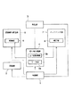
本実施形態は、複数の吐出口から記録媒体ヘインクを吐出して画像を形成する記録部2と、吐出口と対向するように記録媒体を搬送する記録媒体搬送部5と、記録媒体搬送部6内に設けられ、搬送時に負圧を発生させて記録媒体を吸着する吸着部6と、記録部2が駆動する時以外に吐出口が設けられた面に当接して吐出口の保護、及びインク吐出による記録機能の回復を行うメンテナンス部7と、メンテナンス部7内に設けられ、負圧により記録部2から吐出されたインクを吸引する吸引部8と、記録媒体搬送部5及びメンテナンス部7を表裏一体的に配設する可動ユニットを有し、回転による切り換えで、何れか一方を記録部2の吐出口に正対させるための切り換え機構4と、吸引又は吸着のいずれか一方を選択し負圧を与える負圧源9と、これらの構成部位を制御する制御部1とで構成される。この切り換え機構4は、上下回転機構3bと、上下回転機構3bを切り換え駆動させるモータ部3aとで構成される。
In the present embodiment, a
図2、図3を参照して本実施形態に係るラインヘッド機構について説明する。
ヘッドユニット14は、複数色のインク、例えば、ブラック(K)、シアン(C)、マゼンタ(M)、イエロー(Y)等に対応可能な複数のノズル列からなるアレー34を有している。ヘッドユニット14の各色のノズル列は主走査方向に沿って配置される。本実施形態では、吐出口が重力方向(垂直下方向)ヘインクを吐出するように配置される。複数のヘッドユニット14は、ヘッドベース15の両側面に交互に保持されている。ヘッドベース15もノズル列と同様に主走査方向に延びており、両側面に配置されたヘッドユニット14の端部のノズルが記録媒体搬送方向に一部重複するように配置されている。この時、ノズルのピッチは、主走査方向に等間隔のピッチになるように考慮されてヘッドベース15に固定される。
The line head mechanism according to this embodiment will be described with reference to FIGS.
The
このような配置構成においては、各ヘッドユニット14は、記録媒体搬送方向に位置がずれて交互に配置されるため、噴射タイミングが個々に調整される。この調整により複数のヘッドユニット14は、主走査方向即ち、記録媒体11の幅方向に1本のラインを形成することができ、従来の1本のラインヘッドと同等に駆動する。ベルトユニット33は、従動ローラ18と駆動ローラ32とに掛け渡されたエンドレスベルト21が設けられており、回転に伴い記録媒体11を搬送する。従って、ベルトユニット33は、記録媒体11の長さにとらわれることなく、プラテン部の領域で記録媒体11を支持し、搬送するに足る最小の長さ(搬送方向)で有れば良く、省スペースにすることが出来る。
In such an arrangement, the
図2及び図4を参照して記録媒体搬送部5となるベルトユニット33とその周辺部の構成について詳細に説明をする。
ヘッドユニット14に対向して設けられるベルトユニット33は、一対の回転フレーム19により搬送方向両側から挟まれ支持されている。ヘッドユニット14と対向するプラテン部の面には多数の図示していない小径の孔が開口されている。プラテン部におけるベルトユニット33は従動ローラ18と駆動ローラ32とに掛け渡されたエンドレスベルト21を備える。ベルトユニット33におけるエンドレスベルト21上には多数の小径が開口されている。エンドレスベルト内には負圧発生のためのチャンバー22が従動ローラ18と駆動ローラ32との間に設けられる。チャンバー22はヘッドユニット14と対向する面のみに多数の小径が配置されている。位置決め部はヘッドユニット14のインクを吐出するノズル面と記録媒体11との間隔が予め定めた規定値になるようにベルトユニット33側に、回転フレーム19から突出するように形成される位置決め部35が設けられている。
With reference to FIG. 2 and FIG. 4, the configuration of the
The
またベルトユニット33に対向して配置されるヘッドユニット14の周囲には記録媒体11の斜め方向のずれを補正するレジストローラ対10、記録媒体11を搬送するためのガイド対12、バックアップローラ13及び、記録媒体11を排紙ローラ対17へ導くためのガイド16が近接して設けられている。
Further, around the
図2を参照してメンテナンス部7の構成について詳細に説明をする。
メンテナンスユニット31は、ヘッドユニット14と対向するようにキャップ27が複数個設けられている。キャップ27はバネ28によりヘッドユニット14側へ付勢され、バネ28がたわむことにより、インクヘッド部に対向時のみにヘッドユニット14に密着可能である。キャップ27は樹脂やゴム等の弾性部材で形成され、負圧源9に連通した図示しない吸引穴が設けられている。キャップ27はインクパン26の内側に設けられる。インクパン26は、箱形状を成し、キャップ27から溢れたインクがベルトユニット33上に流れ落ちるのを防止するように、その間に設けられる。更に、インクパン26にはインク吸収体25が貼り付けられており、回転フレーム19の回転により、こぼれたインクがベルトユニット33に付着することを防止している。
図4に示すように、回転フレーム19の表裏の両面にメンテナンスユニット31及びベルトユニット33が設けられ、一体的に構成されている。図4においてはベルトユニット33がヘッドユニット14に対向しているが、回転フレーム19が180度回転することによりヘッドユニット14とメンテナンスユニット31が対向可能な機構になっている。
The configuration of the
The
As shown in FIG. 4, a
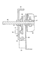
図5及び図6を参照して、回転フレーム19の切り換え機構について説明する。
図5は、左右対になっている回転フレーム19の片側一方の断面を見た図である。この回転フレーム19は、図4に示されたようなベルトユニット33とメンテナンスユニット31を備え、回転フレーム19の両端部は曲げ部20、24を有している。回転フレーム19は回転軸40に軸受け53を介して回転自在に保持され、回転軸40は回転フレーム19の外側に歯車36を固定している。
The switching mechanism of the
FIG. 5 is a view of a cross section of one side of the
回転フレーム19には、回転駆動力を与えるモータ39が固定され、モータ軸には歯車38が取り付けられている。歯車38は回転フレーム19の外側に設けられた歯車36と噛み合い、モータ39の回転に伴い回転軸40が連動する。この画像形成装置本体においては、ブラケット30がヘッドユニット14の下方に一対設けられている。移動フレーム29は、内側に回転フレーム19を挟んで一対設けられ、回転軸40と軸受け41を介して嵌め込まれている。回転軸40の端部には、歯車37が固定されていて、ラック42と噛み合っている。
A
図6は回転フレーム19を側面から見た構成を示した図である。
図6に示す一対のブラケット30には、長手方向に開口される長穴44及びこれと平行してラック42が溶接されて一体的に構成される。回転軸40及び軸43は、重力方向に移動フレーム29を貫通して設けられている。これらの回転軸40とガイド軸43は、両側のブラケット30にそれぞれ設けられた長穴44に係合している。ガイド軸43は移動フレーム29がブラケット30にある長穴44の最下端まで降下した際にストッパガイドとして機能する。回転フレーム19の両端に設けられた曲げ部20、24には図10(b)に示すような穴20a、24aが設けられている。穴20a,24 aは回転方向に若干の遊びを持つように開口されている。移動フレーム29が上昇し、キャップ27がヘッドユニット14に当接し、バネ28が撓められてキャップ27とヘッドユニット14とが密着することで、遊びの範囲内でキャップ27がヘッドユニット14に収まるように設計されている。図6、図9に示すように、移動フレーム29にはソレノイド23が固定されており、そのプランジャー23aが回転フレーム曲げ部20、24に設けられた穴20a、24aに係合する。プランジャー23aが離脱状態で回転フレーム19の回転が許容され、係合状態で回転が防止されるストッパとして機能している。
FIG. 6 is a view showing the configuration of the
The pair of
図2及び図4を参照してプラテン部における記録媒体11による搬送・吸着方法とヘッドユニット14のメンテナンス・吸引方法を説明する。
With reference to FIG. 2 and FIG. 4, a conveyance / suction method by the recording medium 11 in the platen part and a maintenance / suction method of the
まず、記録媒体11は、図示されない記録媒体供給機構により1枚ずつ取り出され、レジストローラ対10に当接して、斜め方向のずれが補正された後、ガイド対12を通り抜け、エンドレスベルト21とバックアップローラ13とからなるニップ部まで搬送される。搬送される際に、記録媒体11はベルトユニット33内に設けられたチャンバー22の負圧吸引によりエンドレスベルト21とチャンバー22のヘッドユニット14に対向する面に備わっている多数の小径を通じてエンドレスベルト21に負圧吸着されて搬送される。
First, the recording medium 11 is taken out one by one by a recording medium supply mechanism (not shown), abuts against the
その際、位置決め部35により記録媒体11とヘッドユニット14との間隔が一定に保持される。ヘッドユニット14と記録媒体11の間隔は1mm〜3mmが一般的であり、この間隔が狭いほど吐出されたインクの着弾精度が向上する。吸着された状態の記録媒体11は、ヘッドユニット14下方のプラテン部へ搬送された後に各ノズルからインクが吐出されて画像形成される。その後、ガイド対16に案内されて、排紙ローラ対17にニップされて装置外へ排出される。
At this time, the distance between the recording medium 11 and the
ヘッドユニット14のメンテナンス・吸引方法においてキャップ27はヘッドユニット14と接触した状態で、ノズル面をゴミや乾燥から保護する働きをする。また、密着した状態で吸引穴に負圧を印加することにより、ヘッドユニット14のノズル内からインクを吸い出し、記録の途中や記録の開始前又は終了後にインクを吐出できなくなったノズルを回復させるように機能する。回復機能は、キャップ27の内部を負圧にして、ヘッド内部のインクをノズルから外に吸い出すことによって、ノズル内に詰まったゴミや気泡の除去を行う。ノズル先端まで引き出されたインクによって、新たにメニスカスが形成され、再び吐出可能となる。
In the maintenance / suction method of the
図7及び図8は、回転フレーム19がメンテナンスユニット31からベルトユニット33への切り替わり方法を示す図である。
図7は、キャップ27がヘッドユニット14のノズル面に密着し、ノズル面を乾燥やホコリ等から保護している状態を示している。この時、回転機構においては、ソレノイド23のプランジャー23aが回転フレーム19と係合した状態のまま、モータ38が(歯車39側から見て)右方向へ回転すると、歯車36を介して歯車36の手前に設けられる回転軸40が回され、歯車36の前に設けられた歯車37が回転駆動される。その後、図5に示されるようにラック42と歯車37が噛み合っていることから、図6に示す移動フレーム29は降下を始める。その結果、キャップ27はヘッドユニット14から離脱する。ガイド軸43の軸受け部がブラケット30の長穴44の最下端に達した時点で降下は停止する。この位置でソレノイド23が駆動して、プランジャー23aを回転フレーム曲げ部20aから離脱させ、モータ39を更に右へ回転駆動させる。歯車37とラック42は噛み合って歯車37が回転できないため、同じ回転軸40に設けられた歯車36も回転できない。よって、歯車38は歯車36に対して遊星歯車となり周りを回動する。その結果、図8に示すように回転フレーム19は回転を始める。ベルトユニット33がヘッドユニット14と対向する位置に来たところで、ソレノイド23の駆動を停止させる。プランジャー23aは曲げ部24に係合され、回転フレーム19が回転を停止する。その状態で、モータ39を左回転させると、今度は噛み合った歯車38、36を介して回転軸40が逆方向に回転され、歯車37とラック42の噛み合いにより、移動フレーム29は上昇を開始する。最上位点は図示しないセンサで検出され、モータ39の駆動を停止させる。
7 and 8 are diagrams illustrating a method of switching the
FIG. 7 shows a state in which the
そのときには、図2に示されるようにヘッドユニット1と対向して、ベルトユニット33が対向している。
逆にベルトユニット33からメンテナンスユニット31への切り換えは、同様にモータ39を歯車38側から見て右回転させて、移動フレーム29が回転し最下点まで移動する。その位置でソレノイド33を動作させることでプランジャー23aは回転フレーム19から離脱し、モータ39が逆回転する。移動フレーム29に保持される全部材の重量を有る程度以上に設定することで、モータ39の駆動力により移動フレーム29は上昇することなく、歯車36の周りを歯車38が遊星歯車となって回転を始め、回転フレーム19が回転する。
At that time, the
Conversely, switching from the
メンテナンスユニット31がヘッドユニット14と対向する位置に来たところで、ソレノイド23の駆動を切り、プランジャー23aを回転フレーム19に係合させて回転を停止させる。
When the
回転が停止されると、モータ39の駆動力が歯車36、歯車37を回転させる力となり、移動フレーム29が上昇する。モータ39と歯車38との間に減速機構の設置がモータ39の駆動が切れても、移動フレーム29が自重により降下することを防止する役割になる。ヘッドユニット14の位置から離間した位置でのベルトユニット33、メンテナンスユニット31の切り換え構成は可動部が周囲と干渉することなく切り換えることを可能としている。
When the rotation is stopped, the driving force of the
本実施形態における切り換え機構は、図2に示すように記録媒体搬送部5の吸着部6とメンテナンス部7の吸引部8が記録部2に対して表裏一体の関係である。画像形成時には、記録媒体11を記録媒体搬送部5に吸着させて一様な間隔を保ちつつ、適正な記録を行う。記録部2は、メンテナンス部7に設けられた吸引部8が記録部2の吐出口が設けられた面に密着し負圧によりインクを吸引している。そのままキャップ27は記録部2に密着して記録部2への塵挨や乾燥を防止する機能をあわせ持つ。切り換え機構4を用いることで記録部2と、記録媒体搬送部5とメンテナンス部7のどちらか一方が対向する状態になる。以上より、本装置はモータ39を駆動源とする回転移動機構であり、移動部であるメンテナンスユニット31とベルトユニット33は、電力供給の配線のみで連結すれば良い。これにより安価で少ないスペースで可動機構を実現する事を可能にしている。
As shown in FIG. 2, the switching mechanism in the present embodiment is such that the
さらに本実施形態では、回転フレームの回転停止はプランジャー23aと回転フレーム19の係合で行うように説明したが、別途回転位置センサを設け、検出される信号により回転位置を停止させても良い。
Further, in the present embodiment, it has been described that the rotation stop of the rotation frame is performed by the engagement of the
また、プランジャー23a以外に別途ストッパ部材を設けて回転角度を規制しても良い。モータ39を駆動源として、ヘッドユニット14に対して離間した位置に可動部を移動させる機構を利用して、記録媒体11の搬送JAMが記録部近傍で発生した際には、ベルトユニット33をヘッドユニット14から離間させ操作者がJAM処理をする事も可能である。
In addition to the
図9は、メンテナンスユニット31からベルトユニット33が回転機構によりヘッドユニット14と対向して上昇する構成について示す図である。
メンテナンスユニット31からベルトユニット33への切り換わりに際に、記録媒体11にインクムラの無い画像形成を実現するためには、ベルトユニット33とヘッドユニット14との間隔が均一で正しく対向するようにさせる必要がある。そのため、回転フレーム19は、回転角の遊び範囲内でヘッドユニット14自身の記録に関与しない部分、あるいはヘッドベース15の一部分、あるいはヘッドベース15を保持する固定フレームの一部分に位置決め部35が当接されて設定される。
FIG. 9 is a diagram showing a configuration in which the
At the time of switching from the
図9では位置決め部35がヘッドユニット14の画像形成に関与しない部分に当接して、ノズル面とエンドレスベルト21とが平行して、所定間隔(約1mm〜3mm)に設定された状態を示している。
FIG. 9 shows a state in which the
以上の構成により、図9に示すように、ベルトユニット33がヘッドユニット14と対向する側に設定する場合には、ベルトユニット33がヘッドユニット14と近接するように上昇して位置決め部35のヘッドユニット14への当接により、間隔が適切に位置決めされる。
With the above configuration, as shown in FIG. 9, when the
本実施形態ではプランジャー23aと回転フレーム19の位置決め穴に遊びを持たせ、回転フレーム19側を動作する構成例とした。しかしこれに限定されるものではなく、回転フレーム19の回転を遊び無く位置決めし、回転フレーム19に対して、ヘッドユニット14が取り付けられたヘッドベース15等のヘッド保持部材側に遊びを持たせることも可能である。あるいは、回転フレーム19の回転の遊びと、ヘッドユニット14を持つヘッド保持部材側の遊びの両方を併用しても良い。
In the present embodiment, a configuration example is provided in which the
図10は、1つの負圧源によりキャップ27と負圧源ベルトユニット33のチャンバー22を切り換えて何れかに負圧を発生させる負圧源の負圧切り換え機構の構成例を示す図である。
FIG. 10 is a diagram showing a configuration example of a negative pressure switching mechanism of a negative pressure source that switches between the
この負圧切り換え機構は、キャップ27内に発生される負圧源とベルトユニット33のチャンバー22に発生される負圧源は、同時に使用されることがないため、同じ1つの負圧源9を用いることができる。負圧源9は、回転軸よりも低い位置に設けられ、負圧源9と繋がっている1本のチューブ46は、回転軸40が嵌合する後述するダイヤル47に連結されている。このダイヤル47には2つの導入口が設けられているため、チューブ46は、途中で上下の2股に分岐されて、それぞれに連結されている。
In this negative pressure switching mechanism, the negative pressure source generated in the
この負圧源9を回転軸40よりも低い位置に設置することは、例えば、メンテナンスユニット31がヘッドユニット14と対向し、ベルトユニット33がメンテナンスユニット31よりも低い側に設定されている時でも、前記分岐箇所がエンドレスベルト21の記録媒体搬送面よりも低い位置になる。従って、メンテナンスユニット31から吸引されたインクがベルトユニット33側へ逆流することが防止できる。また、2股に分岐されたチューブ46は、切り換えダイヤル47に設けられた2つの導入口接続されている。切り換えダイヤル47は、気密で回動可能に連結された2枚の円盤から構成されている。これらの円盤のうち、一方が回転フレーム19側に固定され、他方は図示されていない移動フレーム29に固定される。ダイヤル47は回転軸40と同軸にはめ込まれている。2枚の円盤は、共に180度回転可能である。この回転に伴い、ベルトユニット33のチャンバー22及びメンテナンスユニット31のキャップ27への吸引経路の切り換えが行われる。負圧源9と繋がっているチューブ46は、移動フレーム29に固定された円盤側に作られた導入口に供給されている。
The
それぞれの導入口に2本のチューブが接続されたダイヤル47は、ベルトユニット33のチャンバー22及びメンテナンスユニット31のキャップ27までそれぞれ図示しないチューブ等の部材を用いて吸気系が構築されている。
In the
この吸気系の切り換えは、回転フレーム19の回転に伴うメンテナンスユニット31とベルトユニット33との切り換え動作に連動される。これによりダイヤル47が回転し、負圧源9からの吸引経路が切り換えられる構成である。この構成においては、常にヘッドユニットと対向する側のユニットと負圧源9とが連結されて吸気されている。
The switching of the intake system is linked to the switching operation of the
本実施形態は図10を用い、負圧源9と、メンテナンスユニット31あるいはベルトユニット33との連結切り換えはダイヤル9を用いた構成であった。しかし本発明はこれに限定されることなく、図11のように電磁弁51を用いていずれかのユニットと負圧源を接続するように制御しても良い。
In this embodiment, FIG. 10 is used, and the connection switching between the
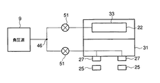
図11は、前述した第1の実施形態における変形例を示して説明する。この変形例は、ダイヤル47の代わりに電磁弁51を用いた構成例である。構成部位について、前述した第1の実施形態と同等の部位には同じ参照符号を付してその詳細な説明は省略する。
FIG. 11 shows a modification of the first embodiment described above. In this modification, a
この変形例は、負圧源9、チューブ46、電磁弁51、ベルトユニット33、チャンバー22、メンテナンスユニット31及びキャップ27により構成されている。2つの電磁弁51は、交互開閉制御を行う。交互開閉制御は負圧源9の負圧をチャンバー22又はキャップ27のどちらか一方にかけることができる。
This modification includes a
図12は、チューブ46の分岐部の高さ位置関係を示す図である。チューブ46の分岐部46aはチャンバー22よりも下方に設けられている構成が望ましい。少なくとも、分岐部46aを境に分岐後のチューブの方が分岐前の部分よりも高い位置に配置されている構成が望ましい。チャンバー22よりも下方に設置された分岐部46aによりキャップ27から吸引されたインクがチャンバー22側へ流れ込むことを防止する。
FIG. 12 is a view showing the height positional relationship of the branch portion of the
逆にメンテナンスユニット31が下方を向いている場合には、キャップ27内部の廃液が垂れる場合がある。そのためインク吸収体25がメンテナンスユニット31の真下に設けられ、装置内をインクで汚染する事を防止している。
On the contrary, when the
本発明ではヘッドユニット14と対向して記録媒体11を搬送する手段として吸引ベルトを有するベルトユニット33を例にとって説明した。しかしながら、本発明はそれに限定されることなく、ベルトを所持しない吸引吸着手段だけでも良い。
In the present invention, the
本実施形態は図7に示すようなヘッドユニット14全体を覆うキャップ27を例にとって説明したが、本発明はこれに限定されることなく単数もしくは複数のノズル列を覆うキャップを用いてもよい。
In the present embodiment, the
本発明は、切り換え機構は吸着部を設けたベルトユニットと吸引部を設けたメンテナンスユニットが表裏一体の関係で組み合わさっている可動ユニットである。ベルトユニットの吸着部とメンテナンスユニットの吸引部は共通の電源を備え、可動ユニットが回転を行う駆動源と回転フレームが上下移動を駆動源が単一である。単一駆動源により回転フレームが180度回転し、ヘッドユニットと対向する可動ユニットを回転させるため、ヘッドユニットを移動させる必要が無い。画像形成時には、ヘッドユニットと対向したベルトユニットがチャンバーによる負圧吸着により搬送された記録媒体11をベルトユニットに吸着させ、位置決め部によりヘッドユニットと記録媒体との間隔一定に保つことで適正な記録を行う。メンテナンス時には、メンテナンス部7に設けられたキャップはインクヘッドのインクを吐出する吐出口に設けられた面に密着し負圧吸引によりヘッド内に取り残されたインクを吸引している。そのままキャップ27は記録部2に密着して記録部2への塵挨や乾燥を防止する機能も備える。ベルトユニットとメンテナンスユニットとの境界部にインク吸収体を設けることでインクヘッドととの対向面を切り換える際にキャップを通じて吸引されたインクが記録媒体搬送手段へ漏れること防止する機能がある。切り換え機構4を用いることで記録部2と、記録媒体搬送部5とメンテナンス部7のどちらか一方が対向する状態になり、対向するユニットのみが電源供給を付与される。以上より本装置は記録媒体搬送手段を通じて記録媒体へのインク付着を防止し、かつラインヘッド機構を省スペースでメンテナンスでき、モータ39を単一駆動源とする回転移動機構であり、メンテナンスユニット内に設けられた吸引部とベルトユニットに設けられた吸着部が単一電源を用いることで安価なメンテナンス機構の実現を可能としている。
According to the present invention, the switching mechanism is a movable unit in which a belt unit provided with a suction portion and a maintenance unit provided with a suction portion are combined in a front-back relationship. The suction unit of the belt unit and the suction unit of the maintenance unit have a common power source, and the drive source that rotates the movable unit and the rotary frame move up and down, and the drive source is single. Since the rotating frame is rotated 180 degrees by a single drive source and the movable unit facing the head unit is rotated, there is no need to move the head unit. At the time of image formation, the belt unit opposed to the head unit adsorbs the recording medium 11 conveyed by negative pressure adsorption by the chamber to the belt unit, and the positioning unit keeps the distance between the head unit and the recording medium constant so that proper recording is performed. I do. At the time of maintenance, the cap provided in the
1:制御部、2:記録部、3:モータ部、4:上下回転移転機構、5:記録媒体搬送部、6:吸着部、7:メンテナンス部、8:吸引部、9:負圧源、10:レジストローラ対、11:記録媒体、12:ガイド対、13:バックアップローラ、14:ヘッドユニット、15:ヘッドベース、16:ガイド対、17:排紙ローラ対、18:従動ローラ、19:回転フレーム、20:回転フレーム曲げ部、21:エンドレスベルト、22:チャンバー、23:ソレノイド、24:回転フレーム曲げ部、25:インク吸収体、26:インクパン、27:キャップ、28:バネ、29:移動フレーム、30:ブラケット、31:メンテナンスユニット、32:駆動ローラ、33:ベルトユニット、34:アレー、35:突き当て部、36:歯車、37:歯車、38:歯車、39:歯車、40:回転軸、41:軸受け、42:ラック、43:軸、44:長穴、45:ジョイント部、46:分岐位置、47:ダイヤル、48:ケース、49:ジョイント部、51:電磁弁、52:プラテンユニット、53:軸受け 1: control unit, 2: recording unit, 3: motor unit, 4: vertical rotation transfer mechanism, 5: recording medium transport unit, 6: suction unit, 7: maintenance unit, 8: suction unit, 9: negative pressure source, 10: registration roller pair, 11: recording medium, 12: guide pair, 13: backup roller, 14: head unit, 15: head base, 16: guide pair, 17: paper discharge roller pair, 18: driven roller, 19: Rotating frame, 20: rotating frame bending part, 21: endless belt, 22: chamber, 23: solenoid, 24: rotating frame bending part, 25: ink absorber, 26: ink pan, 27: cap, 28: spring, 29 : Moving frame, 30: Bracket, 31: Maintenance unit, 32: Drive roller, 33: Belt unit, 34: Array, 35: Abutting part, 36: Gear, 37 Gear: 38: Gear, 39: Gear, 40: Rotating shaft, 41: Bearing, 42: Rack, 43: Shaft, 44: Long hole, 45: Joint part, 46: Branch position, 47: Dial, 48: Case, 49: Joint part, 51: Solenoid valve, 52: Platen unit, 53: Bearing
Claims (11)
前記記録手段のインクを吐出する吐出口と対向するように前記記録媒体を搬送する記録媒体搬送手段と
前記記録手段が駆動する時以外に前記吐出口に当接して該吐出口を保護し、またはインクの吐出による機能回復を行うメンテナンス手段と、
前記記録媒体搬送手段と前記メンテナンス手段とが表裏一体的に配設し、回転可能で前記記録手段と対向して設けられた可動ユニットと、
前記可動ユニットを回転による切り換え制御を行い、前記記録媒体搬送手段又は前記メンテナンス手段のいずれか一方を前記記録手段の吐出口と対向させる切り換え手段と、
を具備することを特徴とする画像形成装置。 A recording means for recording an image by discharging ink to a recording medium;
A recording medium transporting means for transporting the recording medium so as to face an ejection port for ejecting ink of the recording means, and abutting the ejection port to protect the ejection port except when the recording unit is driven, or Maintenance means for recovering the function by discharging ink;
The recording medium conveying means and the maintenance means are arranged integrally on the front and back sides, and a movable unit that is rotatable and provided facing the recording means;
A switching unit that performs switching control by rotation of the movable unit, and makes one of the recording medium conveying unit and the maintenance unit face an ejection port of the recording unit;
An image forming apparatus comprising:
前記記録手段に対して前記離間した位置において、回転により前記記録媒体搬送手段又は前記メンテナンス手段のいずれか一方を選択して、前記吐出口と対向させる回転選択手段と、
を具備することを特徴とする請求項1記載の画像形成装置。 The switching means is a moving means for moving the recording medium conveying means or the maintenance means relative to the recording means between a close position and a separate position;
A rotation selection unit that selects one of the recording medium conveyance unit and the maintenance unit by rotation at a position separated from the recording unit and opposes the discharge port;
2. The image forming apparatus according to claim 1, further comprising:
前記可動ユニットが前記記録手段と近接する位置で前記当接部が該記録手段と当接して位置決めされることを特徴とする請求項1記載の画像形成装置。 Positioning in which a contact portion is arranged in a part of the movable unit combining the recording medium conveying unit and the maintenance unit and the movable unit, and the movable unit provided on the opposing surface of the recording unit is loosely fitted when switching. Having means,
2. The image forming apparatus according to claim 1, wherein the contact portion is positioned in contact with the recording unit at a position where the movable unit is close to the recording unit.
前記メンテナンス手段から前記記録媒体搬送手段へ滴下するインクを吸収することとを特徴とする請求項1記載の画像形成装置。 In addition, the ink holding means disposed between the recording medium conveying means and the maintenance means,
2. The image forming apparatus according to claim 1, wherein ink dripping from the maintenance unit to the recording medium conveying unit is absorbed.
前記メンテナンス手段は、キャップ部材がヘッドユニットを覆った際に前記記録手段からインクを吸引する吸引手段と、
を具備することを特徴とする請求項1記載の画像形成装置。 The recording medium conveying means includes an adsorption means for adsorbing the conveyed recording medium on a conveying belt;
The maintenance means includes a suction means for sucking ink from the recording means when the cap member covers the head unit;
The image forming apparatus according to claim 1, further comprising:
前記記録手段のインクを吐出する吐出口と対向するように前記記録媒体を搬送する記録媒体搬送機構と、
前記記録手段が駆動する時以外に前記吐出口に当接して該吐出口を粉塵や乾燥から前記ヘッド部を保護、またはインクの吐出による記録機能の回復を行うメンテナンス機構と、
前記記録媒体搬送手段と前記メンテナンス手段とが表裏一体的に配設する可動ユニットと、
前記メンテナンス機構内に着脱自在に設けられ、当接により前記ヘッド部を粉塵や乾燥から保護するキャップ部材と、
前記可動ユニットを記録媒体搬送幅方向から両側で回転可能に軸支し前記ヘッド部と対向する位置で保持する一対の回転フレームと、
前記回転フレームに対して前記可動ユニットを相対移動させるための駆動機構と、
前記可動ユニットを回動自在に前記フレームに支持する支持軸と、
前記可動ユニットを前記支持軸中心に回転させる回転機構と、
前記支持軸及び前記可動ユニットを前記ヘッド部に対して所望間隔離れ、往復移動機構と、
を具備することを特徴とする画像形成装置。 A head portion which is a recording means for recording an image by discharging ink to a recording medium;
A recording medium transport mechanism for transporting the recording medium so as to face an ejection port for ejecting ink of the recording means;
A maintenance mechanism that contacts the discharge port other than when the recording unit is driven and protects the head unit from dust and drying, or recovers the recording function by discharging ink;
A movable unit in which the recording medium conveying means and the maintenance means are disposed integrally on the front and back;
A cap member that is detachably provided in the maintenance mechanism and protects the head portion from dust and drying by contact;
A pair of rotating frames that rotatably support the movable unit on both sides from the recording medium conveyance width direction and hold the movable unit at a position facing the head unit;
A drive mechanism for moving the movable unit relative to the rotating frame;
A support shaft that rotatably supports the movable unit on the frame;
A rotation mechanism for rotating the movable unit about the support shaft;
A reciprocating mechanism for separating the support shaft and the movable unit from the head unit by a desired distance;
An image forming apparatus comprising:
Priority Applications (1)
| Application Number | Priority Date | Filing Date | Title |
|---|---|---|---|
| JP2004181129A JP2006001180A (en) | 2004-06-18 | 2004-06-18 | Image forming apparatus |
Applications Claiming Priority (1)
| Application Number | Priority Date | Filing Date | Title |
|---|---|---|---|
| JP2004181129A JP2006001180A (en) | 2004-06-18 | 2004-06-18 | Image forming apparatus |
Publications (2)
| Publication Number | Publication Date |
|---|---|
| JP2006001180A true JP2006001180A (en) | 2006-01-05 |
| JP2006001180A5 JP2006001180A5 (en) | 2007-08-02 |
Family
ID=35769970
Family Applications (1)
| Application Number | Title | Priority Date | Filing Date |
|---|---|---|---|
| JP2004181129A Pending JP2006001180A (en) | 2004-06-18 | 2004-06-18 | Image forming apparatus |
Country Status (1)
| Country | Link |
|---|---|
| JP (1) | JP2006001180A (en) |
Cited By (4)
| Publication number | Priority date | Publication date | Assignee | Title |
|---|---|---|---|---|
| JP2008013283A (en) * | 2006-07-03 | 2008-01-24 | Ricoh Co Ltd | Belt conveying device and image forming device |
| JP2008229982A (en) * | 2007-03-19 | 2008-10-02 | Olympus Corp | Image forming system having built-in maintenance mechanism |
| JP2009160853A (en) * | 2008-01-08 | 2009-07-23 | Ricoh Co Ltd | Image forming apparatus |
| JP2010005997A (en) * | 2008-06-30 | 2010-01-14 | Fujifilm Corp | Inkjet recorder and head maintenance method |
Citations (6)
| Publication number | Priority date | Publication date | Assignee | Title |
|---|---|---|---|---|
| JPH08336984A (en) * | 1995-06-09 | 1996-12-24 | Tec Corp | Ink jet printer |
| JP2000062151A (en) * | 1998-08-18 | 2000-02-29 | Konica Corp | Liquid jet printer |
| JP2000246909A (en) * | 1999-03-01 | 2000-09-12 | Seiko Instruments Inc | Ink jet recorder |
| JP2002356026A (en) * | 2001-05-31 | 2002-12-10 | Sharp Corp | Ink jet printer |
| JP2003011377A (en) * | 2001-07-04 | 2003-01-15 | Olympus Optical Co Ltd | Ink-jet printer and recovery unit for ink-jet printer |
| JP2005103770A (en) * | 2003-09-26 | 2005-04-21 | Fuji Photo Film Co Ltd | Image forming device |
-
2004
- 2004-06-18 JP JP2004181129A patent/JP2006001180A/en active Pending
Patent Citations (6)
| Publication number | Priority date | Publication date | Assignee | Title |
|---|---|---|---|---|
| JPH08336984A (en) * | 1995-06-09 | 1996-12-24 | Tec Corp | Ink jet printer |
| JP2000062151A (en) * | 1998-08-18 | 2000-02-29 | Konica Corp | Liquid jet printer |
| JP2000246909A (en) * | 1999-03-01 | 2000-09-12 | Seiko Instruments Inc | Ink jet recorder |
| JP2002356026A (en) * | 2001-05-31 | 2002-12-10 | Sharp Corp | Ink jet printer |
| JP2003011377A (en) * | 2001-07-04 | 2003-01-15 | Olympus Optical Co Ltd | Ink-jet printer and recovery unit for ink-jet printer |
| JP2005103770A (en) * | 2003-09-26 | 2005-04-21 | Fuji Photo Film Co Ltd | Image forming device |
Cited By (6)
| Publication number | Priority date | Publication date | Assignee | Title |
|---|---|---|---|---|
| JP2008013283A (en) * | 2006-07-03 | 2008-01-24 | Ricoh Co Ltd | Belt conveying device and image forming device |
| JP4566954B2 (en) * | 2006-07-03 | 2010-10-20 | 株式会社リコー | Belt conveying apparatus and image forming apparatus |
| US8052276B2 (en) | 2006-07-03 | 2011-11-08 | Ricoh Company, Ltd. | Image forming apparatus and belt conveying device |
| JP2008229982A (en) * | 2007-03-19 | 2008-10-02 | Olympus Corp | Image forming system having built-in maintenance mechanism |
| JP2009160853A (en) * | 2008-01-08 | 2009-07-23 | Ricoh Co Ltd | Image forming apparatus |
| JP2010005997A (en) * | 2008-06-30 | 2010-01-14 | Fujifilm Corp | Inkjet recorder and head maintenance method |
Similar Documents
| Publication | Publication Date | Title |
|---|---|---|
| JP5445013B2 (en) | Inkjet recording apparatus and image forming apparatus | |
| JP2006159556A (en) | Liquid ejecting apparatus and liquid spare ejection method in liquid ejecting apparatus | |
| JP2009143071A (en) | Liquid jet device | |
| JP2011025496A (en) | Inkjet recording apparatus | |
| US7798597B2 (en) | Inkjet recording device | |
| JP4269960B2 (en) | Medium conveying apparatus and recording apparatus | |
| JP4586923B2 (en) | Medium conveying apparatus and recording apparatus | |
| JP2010023374A (en) | Image recording device | |
| JP2009132500A (en) | Recording medium conveying device, and recording device including the same | |
| JP2007131372A (en) | Ink jet recording device | |
| JP4543682B2 (en) | Inkjet recording device | |
| JP2006001180A (en) | Image forming apparatus | |
| JP4586924B2 (en) | Medium conveying apparatus and recording apparatus | |
| JP4543681B2 (en) | Inkjet recording device | |
| JP4487526B2 (en) | Recording device | |
| JP5262365B2 (en) | Liquid discharge recording apparatus and ink jet recording apparatus | |
| JP2009132057A (en) | Recording device | |
| JP2009132515A (en) | Recording device | |
| JP2010046886A (en) | Printer | |
| JP2017189896A (en) | Liquid injection device | |
| JP2009125964A (en) | Inkjet image forming apparatus | |
| WO2015064092A9 (en) | Printing device and printing device control method | |
| JP2006001181A (en) | Image forming apparatus with negative pressure switching mechanism | |
| JP4487951B2 (en) | Inkjet recording device | |
| JP2010214819A (en) | Image forming apparatus |
Legal Events
| Date | Code | Title | Description |
|---|---|---|---|
| A521 | Written amendment |
Free format text: JAPANESE INTERMEDIATE CODE: A523 Effective date: 20070614 |
|
| A621 | Written request for application examination |
Free format text: JAPANESE INTERMEDIATE CODE: A621 Effective date: 20070614 |
|
| A131 | Notification of reasons for refusal |
Free format text: JAPANESE INTERMEDIATE CODE: A131 Effective date: 20091222 |
|
| A02 | Decision of refusal |
Free format text: JAPANESE INTERMEDIATE CODE: A02 Effective date: 20100413 |