JP4763709B2 - Lighting assembly using strip with circuit - Google Patents
Lighting assembly using strip with circuit Download PDFInfo
- Publication number
- JP4763709B2 JP4763709B2 JP2007540306A JP2007540306A JP4763709B2 JP 4763709 B2 JP4763709 B2 JP 4763709B2 JP 2007540306 A JP2007540306 A JP 2007540306A JP 2007540306 A JP2007540306 A JP 2007540306A JP 4763709 B2 JP4763709 B2 JP 4763709B2
- Authority
- JP
- Japan
- Prior art keywords
- substrate
- led
- strip
- circuit
- leds
- Prior art date
- Legal status (The legal status is an assumption and is not a legal conclusion. Google has not performed a legal analysis and makes no representation as to the accuracy of the status listed.)
- Expired - Fee Related
Links
- 239000000758 substrate Substances 0.000 claims description 66
- 230000017525 heat dissipation Effects 0.000 claims description 46
- 238000004519 manufacturing process Methods 0.000 claims description 7
- 238000005286 illumination Methods 0.000 claims description 3
- 239000008393 encapsulating agent Substances 0.000 description 15
- 229910000679 solder Inorganic materials 0.000 description 15
- 239000000463 material Substances 0.000 description 14
- 229910052751 metal Inorganic materials 0.000 description 13
- 239000002184 metal Substances 0.000 description 13
- 239000010408 film Substances 0.000 description 12
- 239000000853 adhesive Substances 0.000 description 11
- 230000001070 adhesive effect Effects 0.000 description 11
- 239000012788 optical film Substances 0.000 description 11
- 238000000034 method Methods 0.000 description 8
- 238000005476 soldering Methods 0.000 description 7
- 238000002310 reflectometry Methods 0.000 description 6
- 239000010931 gold Substances 0.000 description 5
- 230000003287 optical effect Effects 0.000 description 5
- 229920000642 polymer Polymers 0.000 description 5
- PXHVJJICTQNCMI-UHFFFAOYSA-N Nickel Chemical compound [Ni] PXHVJJICTQNCMI-UHFFFAOYSA-N 0.000 description 4
- 230000008901 benefit Effects 0.000 description 4
- 238000001465 metallisation Methods 0.000 description 4
- 239000004065 semiconductor Substances 0.000 description 4
- 230000003595 spectral effect Effects 0.000 description 4
- RYGMFSIKBFXOCR-UHFFFAOYSA-N Copper Chemical compound [Cu] RYGMFSIKBFXOCR-UHFFFAOYSA-N 0.000 description 3
- 239000004642 Polyimide Substances 0.000 description 3
- 230000000712 assembly Effects 0.000 description 3
- 238000000429 assembly Methods 0.000 description 3
- 239000004020 conductor Substances 0.000 description 3
- 229910052802 copper Inorganic materials 0.000 description 3
- 239000010949 copper Substances 0.000 description 3
- 230000005496 eutectics Effects 0.000 description 3
- 229920001721 polyimide Polymers 0.000 description 3
- 229910002601 GaN Inorganic materials 0.000 description 2
- JMASRVWKEDWRBT-UHFFFAOYSA-N Gallium nitride Chemical compound [Ga]#N JMASRVWKEDWRBT-UHFFFAOYSA-N 0.000 description 2
- 229910052782 aluminium Inorganic materials 0.000 description 2
- XAGFODPZIPBFFR-UHFFFAOYSA-N aluminium Chemical compound [Al] XAGFODPZIPBFFR-UHFFFAOYSA-N 0.000 description 2
- 230000003098 cholesteric effect Effects 0.000 description 2
- 239000002131 composite material Substances 0.000 description 2
- 230000002950 deficient Effects 0.000 description 2
- 238000009826 distribution Methods 0.000 description 2
- 230000000694 effects Effects 0.000 description 2
- 239000012530 fluid Substances 0.000 description 2
- PCHJSUWPFVWCPO-UHFFFAOYSA-N gold Chemical compound [Au] PCHJSUWPFVWCPO-UHFFFAOYSA-N 0.000 description 2
- 229910052737 gold Inorganic materials 0.000 description 2
- 229910052738 indium Inorganic materials 0.000 description 2
- APFVFJFRJDLVQX-UHFFFAOYSA-N indium atom Chemical compound [In] APFVFJFRJDLVQX-UHFFFAOYSA-N 0.000 description 2
- 229910052759 nickel Inorganic materials 0.000 description 2
- 230000000737 periodic effect Effects 0.000 description 2
- 229920000139 polyethylene terephthalate Polymers 0.000 description 2
- 239000005020 polyethylene terephthalate Substances 0.000 description 2
- 239000007787 solid Substances 0.000 description 2
- 229910052582 BN Inorganic materials 0.000 description 1
- PZNSFCLAULLKQX-UHFFFAOYSA-N Boron nitride Chemical compound N#B PZNSFCLAULLKQX-UHFFFAOYSA-N 0.000 description 1
- OKTJSMMVPCPJKN-UHFFFAOYSA-N Carbon Chemical compound [C] OKTJSMMVPCPJKN-UHFFFAOYSA-N 0.000 description 1
- VYZAMTAEIAYCRO-UHFFFAOYSA-N Chromium Chemical compound [Cr] VYZAMTAEIAYCRO-UHFFFAOYSA-N 0.000 description 1
- 239000004593 Epoxy Substances 0.000 description 1
- 229910005540 GaP Inorganic materials 0.000 description 1
- OAICVXFJPJFONN-UHFFFAOYSA-N Phosphorus Chemical compound [P] OAICVXFJPJFONN-UHFFFAOYSA-N 0.000 description 1
- ATJFFYVFTNAWJD-UHFFFAOYSA-N Tin Chemical compound [Sn] ATJFFYVFTNAWJD-UHFFFAOYSA-N 0.000 description 1
- 230000006978 adaptation Effects 0.000 description 1
- 230000002730 additional effect Effects 0.000 description 1
- 229910045601 alloy Inorganic materials 0.000 description 1
- 239000000956 alloy Substances 0.000 description 1
- 239000012080 ambient air Substances 0.000 description 1
- 230000005540 biological transmission Effects 0.000 description 1
- 229920001400 block copolymer Polymers 0.000 description 1
- 238000003486 chemical etching Methods 0.000 description 1
- 239000003086 colorant Substances 0.000 description 1
- 238000010276 construction Methods 0.000 description 1
- 239000002826 coolant Substances 0.000 description 1
- WUUZKBJEUBFVMV-UHFFFAOYSA-N copper molybdenum Chemical compound [Cu].[Mo] WUUZKBJEUBFVMV-UHFFFAOYSA-N 0.000 description 1
- 230000001066 destructive effect Effects 0.000 description 1
- 238000005516 engineering process Methods 0.000 description 1
- 238000005530 etching Methods 0.000 description 1
- 238000000605 extraction Methods 0.000 description 1
- HZXMRANICFIONG-UHFFFAOYSA-N gallium phosphide Chemical compound [Ga]#P HZXMRANICFIONG-UHFFFAOYSA-N 0.000 description 1
- 229910002804 graphite Inorganic materials 0.000 description 1
- 239000010439 graphite Substances 0.000 description 1
- 229910021478 group 5 element Inorganic materials 0.000 description 1
- 229910010272 inorganic material Inorganic materials 0.000 description 1
- 239000011147 inorganic material Substances 0.000 description 1
- 239000007788 liquid Substances 0.000 description 1
- 230000000873 masking effect Effects 0.000 description 1
- 230000007246 mechanism Effects 0.000 description 1
- 239000007769 metal material Substances 0.000 description 1
- 238000003801 milling Methods 0.000 description 1
- 150000004767 nitrides Chemical class 0.000 description 1
- 238000001020 plasma etching Methods 0.000 description 1
- 230000010287 polarization Effects 0.000 description 1
- 229920003223 poly(pyromellitimide-1,4-diphenyl ether) Polymers 0.000 description 1
- 229920002492 poly(sulfone) Polymers 0.000 description 1
- 229920000515 polycarbonate Polymers 0.000 description 1
- 239000004417 polycarbonate Substances 0.000 description 1
- 229920000728 polyester Polymers 0.000 description 1
- -1 polyethylene terephthalate Polymers 0.000 description 1
- 239000002861 polymer material Substances 0.000 description 1
- 229920001296 polysiloxane Polymers 0.000 description 1
- 230000008569 process Effects 0.000 description 1
- 230000001681 protective effect Effects 0.000 description 1
- 238000004080 punching Methods 0.000 description 1
- 238000003892 spreading Methods 0.000 description 1
- 230000007480 spreading Effects 0.000 description 1
- 239000000126 substance Substances 0.000 description 1
- 229910052718 tin Inorganic materials 0.000 description 1
Images


Classifications
-
- H—ELECTRICITY
- H05—ELECTRIC TECHNIQUES NOT OTHERWISE PROVIDED FOR
- H05K—PRINTED CIRCUITS; CASINGS OR CONSTRUCTIONAL DETAILS OF ELECTRIC APPARATUS; MANUFACTURE OF ASSEMBLAGES OF ELECTRICAL COMPONENTS
- H05K1/00—Printed circuits
- H05K1/02—Details
- H05K1/0201—Thermal arrangements, e.g. for cooling, heating or preventing overheating
- H05K1/0203—Cooling of mounted components
-
- H—ELECTRICITY
- H01—ELECTRIC ELEMENTS
- H01L—SEMICONDUCTOR DEVICES NOT COVERED BY CLASS H10
- H01L2224/00—Indexing scheme for arrangements for connecting or disconnecting semiconductor or solid-state bodies and methods related thereto as covered by H01L24/00
- H01L2224/01—Means for bonding being attached to, or being formed on, the surface to be connected, e.g. chip-to-package, die-attach, "first-level" interconnects; Manufacturing methods related thereto
- H01L2224/42—Wire connectors; Manufacturing methods related thereto
- H01L2224/47—Structure, shape, material or disposition of the wire connectors after the connecting process
- H01L2224/48—Structure, shape, material or disposition of the wire connectors after the connecting process of an individual wire connector
- H01L2224/4805—Shape
- H01L2224/4809—Loop shape
- H01L2224/48091—Arched
-
- H—ELECTRICITY
- H01—ELECTRIC ELEMENTS
- H01L—SEMICONDUCTOR DEVICES NOT COVERED BY CLASS H10
- H01L2224/00—Indexing scheme for arrangements for connecting or disconnecting semiconductor or solid-state bodies and methods related thereto as covered by H01L24/00
- H01L2224/01—Means for bonding being attached to, or being formed on, the surface to be connected, e.g. chip-to-package, die-attach, "first-level" interconnects; Manufacturing methods related thereto
- H01L2224/42—Wire connectors; Manufacturing methods related thereto
- H01L2224/47—Structure, shape, material or disposition of the wire connectors after the connecting process
- H01L2224/48—Structure, shape, material or disposition of the wire connectors after the connecting process of an individual wire connector
- H01L2224/481—Disposition
- H01L2224/48151—Connecting between a semiconductor or solid-state body and an item not being a semiconductor or solid-state body, e.g. chip-to-substrate, chip-to-passive
- H01L2224/48221—Connecting between a semiconductor or solid-state body and an item not being a semiconductor or solid-state body, e.g. chip-to-substrate, chip-to-passive the body and the item being stacked
- H01L2224/48225—Connecting between a semiconductor or solid-state body and an item not being a semiconductor or solid-state body, e.g. chip-to-substrate, chip-to-passive the body and the item being stacked the item being non-metallic, e.g. insulating substrate with or without metallisation
- H01L2224/48227—Connecting between a semiconductor or solid-state body and an item not being a semiconductor or solid-state body, e.g. chip-to-substrate, chip-to-passive the body and the item being stacked the item being non-metallic, e.g. insulating substrate with or without metallisation connecting the wire to a bond pad of the item
-
- H—ELECTRICITY
- H01—ELECTRIC ELEMENTS
- H01L—SEMICONDUCTOR DEVICES NOT COVERED BY CLASS H10
- H01L2924/00—Indexing scheme for arrangements or methods for connecting or disconnecting semiconductor or solid-state bodies as covered by H01L24/00
- H01L2924/01—Chemical elements
- H01L2924/01079—Gold [Au]
-
- H—ELECTRICITY
- H01—ELECTRIC ELEMENTS
- H01L—SEMICONDUCTOR DEVICES NOT COVERED BY CLASS H10
- H01L2924/00—Indexing scheme for arrangements or methods for connecting or disconnecting semiconductor or solid-state bodies as covered by H01L24/00
- H01L2924/013—Alloys
- H01L2924/0132—Binary Alloys
- H01L2924/01322—Eutectic Alloys, i.e. obtained by a liquid transforming into two solid phases
-
- H—ELECTRICITY
- H01—ELECTRIC ELEMENTS
- H01L—SEMICONDUCTOR DEVICES NOT COVERED BY CLASS H10
- H01L2924/00—Indexing scheme for arrangements or methods for connecting or disconnecting semiconductor or solid-state bodies as covered by H01L24/00
- H01L2924/10—Details of semiconductor or other solid state devices to be connected
- H01L2924/11—Device type
- H01L2924/12—Passive devices, e.g. 2 terminal devices
- H01L2924/1204—Optical Diode
- H01L2924/12041—LED
-
- H—ELECTRICITY
- H01—ELECTRIC ELEMENTS
- H01L—SEMICONDUCTOR DEVICES NOT COVERED BY CLASS H10
- H01L2924/00—Indexing scheme for arrangements or methods for connecting or disconnecting semiconductor or solid-state bodies as covered by H01L24/00
- H01L2924/15—Details of package parts other than the semiconductor or other solid state devices to be connected
- H01L2924/151—Die mounting substrate
- H01L2924/1515—Shape
- H01L2924/15153—Shape the die mounting substrate comprising a recess for hosting the device
-
- H—ELECTRICITY
- H01—ELECTRIC ELEMENTS
- H01L—SEMICONDUCTOR DEVICES NOT COVERED BY CLASS H10
- H01L2924/00—Indexing scheme for arrangements or methods for connecting or disconnecting semiconductor or solid-state bodies as covered by H01L24/00
- H01L2924/15—Details of package parts other than the semiconductor or other solid state devices to be connected
- H01L2924/151—Die mounting substrate
- H01L2924/1517—Multilayer substrate
-
- H—ELECTRICITY
- H01—ELECTRIC ELEMENTS
- H01L—SEMICONDUCTOR DEVICES NOT COVERED BY CLASS H10
- H01L2924/00—Indexing scheme for arrangements or methods for connecting or disconnecting semiconductor or solid-state bodies as covered by H01L24/00
- H01L2924/30—Technical effects
- H01L2924/301—Electrical effects
- H01L2924/3025—Electromagnetic shielding
-
- H—ELECTRICITY
- H01—ELECTRIC ELEMENTS
- H01L—SEMICONDUCTOR DEVICES NOT COVERED BY CLASS H10
- H01L33/00—Semiconductor devices having potential barriers specially adapted for light emission; Processes or apparatus specially adapted for the manufacture or treatment thereof or of parts thereof; Details thereof
- H01L33/48—Semiconductor devices having potential barriers specially adapted for light emission; Processes or apparatus specially adapted for the manufacture or treatment thereof or of parts thereof; Details thereof characterised by the semiconductor body packages
- H01L33/62—Arrangements for conducting electric current to or from the semiconductor body, e.g. lead-frames, wire-bonds or solder balls
-
- H—ELECTRICITY
- H05—ELECTRIC TECHNIQUES NOT OTHERWISE PROVIDED FOR
- H05K—PRINTED CIRCUITS; CASINGS OR CONSTRUCTIONAL DETAILS OF ELECTRIC APPARATUS; MANUFACTURE OF ASSEMBLAGES OF ELECTRICAL COMPONENTS
- H05K1/00—Printed circuits
- H05K1/18—Printed circuits structurally associated with non-printed electric components
- H05K1/182—Printed circuits structurally associated with non-printed electric components associated with components mounted in the printed circuit board, e.g. insert mounted components [IMC]
-
- H—ELECTRICITY
- H05—ELECTRIC TECHNIQUES NOT OTHERWISE PROVIDED FOR
- H05K—PRINTED CIRCUITS; CASINGS OR CONSTRUCTIONAL DETAILS OF ELECTRIC APPARATUS; MANUFACTURE OF ASSEMBLAGES OF ELECTRICAL COMPONENTS
- H05K2201/00—Indexing scheme relating to printed circuits covered by H05K1/00
- H05K2201/06—Thermal details
- H05K2201/066—Heatsink mounted on the surface of the printed circuit board [PCB]
-
- H—ELECTRICITY
- H05—ELECTRIC TECHNIQUES NOT OTHERWISE PROVIDED FOR
- H05K—PRINTED CIRCUITS; CASINGS OR CONSTRUCTIONAL DETAILS OF ELECTRIC APPARATUS; MANUFACTURE OF ASSEMBLAGES OF ELECTRICAL COMPONENTS
- H05K2201/00—Indexing scheme relating to printed circuits covered by H05K1/00
- H05K2201/10—Details of components or other objects attached to or integrated in a printed circuit board
- H05K2201/10007—Types of components
- H05K2201/10106—Light emitting diode [LED]
-
- H—ELECTRICITY
- H05—ELECTRIC TECHNIQUES NOT OTHERWISE PROVIDED FOR
- H05K—PRINTED CIRCUITS; CASINGS OR CONSTRUCTIONAL DETAILS OF ELECTRIC APPARATUS; MANUFACTURE OF ASSEMBLAGES OF ELECTRICAL COMPONENTS
- H05K3/00—Apparatus or processes for manufacturing printed circuits
- H05K3/0097—Processing two or more printed circuits simultaneously, e.g. made from a common substrate, or temporarily stacked circuit boards
-
- Y—GENERAL TAGGING OF NEW TECHNOLOGICAL DEVELOPMENTS; GENERAL TAGGING OF CROSS-SECTIONAL TECHNOLOGIES SPANNING OVER SEVERAL SECTIONS OF THE IPC; TECHNICAL SUBJECTS COVERED BY FORMER USPC CROSS-REFERENCE ART COLLECTIONS [XRACs] AND DIGESTS
- Y10—TECHNICAL SUBJECTS COVERED BY FORMER USPC
- Y10S—TECHNICAL SUBJECTS COVERED BY FORMER USPC CROSS-REFERENCE ART COLLECTIONS [XRACs] AND DIGESTS
- Y10S362/00—Illumination
- Y10S362/80—Light emitting diode
Landscapes
- Engineering & Computer Science (AREA)
- Microelectronics & Electronic Packaging (AREA)
- Non-Portable Lighting Devices Or Systems Thereof (AREA)
- Fastening Of Light Sources Or Lamp Holders (AREA)
- Arrangement Of Elements, Cooling, Sealing, Or The Like Of Lighting Devices (AREA)
- Led Device Packages (AREA)
Description
本発明は、概して、ライティング又は照明の組立品に関する。とりわけ、本発明は、発光ダイオード(LED)の配列を使用する、ライティング又は照明の組立品に関する。 The present invention relates generally to lighting or lighting assemblies. In particular, the present invention relates to a lighting or lighting assembly that uses an array of light emitting diodes (LEDs).
照明システムは、種々多様な用途に使用される。従来の照明システムは、例えば白熱灯又は蛍光灯などの光源を使用してきた。より最近では、他のタイプの発光素子、特に発光ダイオード(LED)が、照明システムで使用されてきている。LEDは、サイズが小さい、寿命が長い、消費電力が少ないという利点を有する。LEDは、これらの利点により、数多くの多様な用途において有用になっており、しばしば他の光源に取って代わっている。 Lighting systems are used in a wide variety of applications. Conventional lighting systems have used light sources such as incandescent lamps or fluorescent lamps. More recently, other types of light emitting elements, particularly light emitting diodes (LEDs), have been used in lighting systems. LEDs have the advantages of small size, long life, and low power consumption. Due to these advantages, LEDs have become useful in a number of diverse applications, often replacing other light sources.
多くのライティング用途では、複数のLEDで、必要とされる光の強度及び/もしくは光の分布を供給することが必要であるかもしくは望ましい。例えば、複数のLEDが、小さな寸法を有する配列(アレイ)に組み立てられて、小さな面積で高い照度を提供すること、又はより広い面積にわたり分布されて、より広い及びより均一な照度を提供することが可能である。 In many lighting applications, it is necessary or desirable to provide the required light intensity and / or light distribution with multiple LEDs. For example, multiple LEDs can be assembled into an array with small dimensions to provide high illumination in a small area, or distributed over a larger area to provide wider and more uniform illumination Is possible.
アレイ状のLEDは、一般に、プリント基板上への実装により、相互に及び他の電気システムに接続される。しかしながら、LEDが(例えば、大きな高性能ディスプレイデバイスを背面照射するときのように)広い面積にわたる分布を必要とされるとき、プリント基板の使用は、幾つかの理由で問題となる。例えば、プリント基板は、幾つかのディスプレイデバイスに必要とされるサイズ及び形状(例えば、非常に長くて細いストリップ)では、生産及び/又は取扱いが困難なことがある。特に、プリント基板が非平面形状に適応しなければならない場合、プリント基板の材料の剛性により、製造又は組立が困難になることがある。加えて、LEDの放熱条件が、従来のプリント基板の構成によって満たされないことがある。したがって、これらの問題に対処する照明組立品が必要とされる。 Arrayed LEDs are typically connected to each other and to other electrical systems by mounting on a printed circuit board. However, when LEDs are required to be distributed over a large area (e.g., when backlighting large high performance display devices), the use of printed circuit boards becomes problematic for several reasons. For example, printed circuit boards may be difficult to produce and / or handle in the size and shape required for some display devices (eg, very long and thin strips). In particular, if the printed circuit board must accommodate a non-planar shape, the rigidity of the printed circuit board material can make manufacturing or assembly difficult. In addition, the heat dissipation condition of the LED may not be satisfied by the configuration of the conventional printed circuit board. Therefore, there is a need for a lighting assembly that addresses these issues.
本出願は、LEDの配列(アレイ)を使用する照明組立品を開示する。幾つかの実施形態では、本組立品は、間隔のある関係で上に配置された複数の回路付きストリップを有する、放熱部材を含む。各回路付きストリップには、電気絶縁性の基材が含まれ、基材の第一の側上に少なくとも1つの回路配線を有し、その基材の第二の側上に導電性及び熱伝導性の層を有しており、少なくとも1つの回路配線が、基材の第二の側から電気的に絶縁されている。回路付きストリップはまた、基材の第一の側から第二の側まで延びる複数のビアを有する。複数のLEDが、複数のビアの中に配置される。LEDのそれぞれは、基材の第二の側上の導電性及び熱伝導性の層の上に配置され、基材の第一の側上の少なくとも1つの回路配線に電気接続される。 The present application discloses a lighting assembly that uses an array of LEDs. In some embodiments, the assembly includes a heat dissipating member having a plurality of circuitized strips disposed thereon in a spaced relationship. Each circuit strip includes an electrically insulating substrate, has at least one circuit wiring on the first side of the substrate, and is electrically and thermally conductive on the second side of the substrate. And at least one circuit wiring is electrically insulated from the second side of the substrate. The circuitized strip also has a plurality of vias extending from the first side to the second side of the substrate. A plurality of LEDs are arranged in the plurality of vias. Each of the LEDs is disposed on a conductive and thermally conductive layer on the second side of the substrate and is electrically connected to at least one circuit wiring on the first side of the substrate.
幾つかの実施形態では、本組立品は、基材の第一の側上の少なくとも1つの回路配線と基材の第一の側から第二の側まで延びる複数のビアとを有する電気絶縁性基材を有する、可撓性の回路を含む。LEDが、少なくとも1つのビアの中に配置され、導電性の放熱部材が、可撓性回路の第二の側に近接して配置される。LEDは、放熱部材と少なくとも1つの回路配線との両方に電気接続される。 In some embodiments, the assembly is electrically insulating having at least one circuit wiring on a first side of the substrate and a plurality of vias extending from the first side to the second side of the substrate. A flexible circuit having a substrate is included. An LED is disposed in the at least one via and a conductive heat dissipation member is disposed proximate to the second side of the flexible circuit. The LED is electrically connected to both the heat dissipation member and at least one circuit wiring.
照明組立品を製造する方法も開示される。幾つかの実施形態では、本方法は、絶縁性基材を提供することと、絶縁性基材の上に複数の回路配線を提供することと、絶縁性基材に複数列のビアを設けること(ビアの各列は少なくとも1つの関連付けられた回路配線を有する)と、基材を複数のストリップに分離すること(各ストリップにビアの複数列の1つと、関連付けられた回路配線とが含まれる)と、各ストリップの少なくとも1つのビアにLEDを装着して、そのLEDを関連付けられた回路配線に電気接続することと、複数のストリップの少なくとも2つをヒートシンク上に配置してLEDの配列を形成し、各ストリップのLEDをヒートシンクに電気接続することとを含む。 A method of manufacturing a lighting assembly is also disclosed. In some embodiments, the method provides an insulating substrate, provides a plurality of circuit wires on the insulating substrate, and provides a plurality of rows of vias on the insulating substrate. (Each row of vias has at least one associated circuit wiring) and separating the substrate into multiple strips (each strip including one of the multiple rows of vias and associated circuit wiring) ), Mounting the LEDs in at least one via in each strip, electrically connecting the LEDs to the associated circuit wiring, and placing at least two of the plurality of strips on a heat sink to arrange the LEDs Forming and electrically connecting each strip of LEDs to a heat sink.
以下の説明では、添付の図面を参照する。他の実施形態も使用可能であること、及び構造的又は論理的な変更がなされてもよいことを、読者は理解するであろう。したがって、以下の詳細説明は、制限する意味で理解されるべきではなく、本発明の範囲は、付随する請求項によって定義される。 In the following description, reference is made to the accompanying drawings. The reader will understand that other embodiments may be used and structural or logical changes may be made. The following detailed description is, therefore, not to be taken in a limiting sense, and the scope of the present invention is defined by the appended claims.
本明細書で使用するとき、用語「LED」及び「発光ダイオード」は一般に、ダイオードに電力を供給するための接触(コンタクト)域が付いた発光半導体素子を指すために使用されている。種々の形態の無機半導体発光ダイオードは、例えば1つ以上の第III族元素と1つ以上の第V族元素との組み合わせ(III−V族半導体)から形成されてもよい。LEDに使用可能なIII−V族半導体材料の例として、ガリウムナイトライド又はインジウムガリウムナイトライドなどの窒化物、及びインジウムガリウムホスファイドなどのリン化物が挙げられる。他のタイプのIII−V族材料も使用可能であり、また同様に、周期表の他の族の無機物質も使用可能である。 As used herein, the terms “LED” and “light emitting diode” are generally used to refer to a light emitting semiconductor device with a contact area for supplying power to the diode. Various forms of inorganic semiconductor light emitting diodes may be formed, for example, from a combination of one or more Group III elements and one or more Group V elements (III-V semiconductor). Examples of III-V semiconductor materials that can be used in LEDs include nitrides such as gallium nitride or indium gallium nitride, and phosphides such as indium gallium phosphide. Other types of III-V materials can be used, as well as inorganic materials from other groups of the periodic table.
LEDは、パッケージ化された形態であっても、又はパッケージ化されていない形態であってもよく、例えばLEDダイ、表面実装型LED、チップオンボード型LED、及び他の構成のLEDが含まれる。チップオンボード(COB)とは、例えばワイヤボンディングを使用して従来法で基板に相互連結される、面を上にして固着されるチップデバイスを用いる、ハイブリッド技術を指す。用語LEDは、蛍光体と共にパッケージ化された又はこれに関連付けられたLEDをも含み、蛍光体が、LEDから放たれる光を異なる波長の光に変換する。LEDへの電気接続は、ワイヤボンディング、テープ自動化ボンディング(TAB)、又はフリップチップボンディングにより行うことができる。LEDは、図面において概略的に示されており、本明細書で説明するように、非パッケージ化LEDダイでも、又はパッケージ化されたLEDでもあることができる。 The LEDs may be packaged or unpackaged, and include, for example, LED dies, surface mount LEDs, chip on board LEDs, and other configurations of LEDs. . Chip-on-board (COB) refers to a hybrid technology that uses chip devices that are bonded face-up and interconnected to a substrate in a conventional manner using, for example, wire bonding. The term LED also includes LEDs packaged with or associated with a phosphor, which converts the light emitted from the LED into light of a different wavelength. Electrical connection to the LED can be made by wire bonding, tape automated bonding (TAB), or flip chip bonding. The LEDs are shown schematically in the drawings and can be unpackaged LED dies or packaged LEDs as described herein.
LEDは、赤、緑、青、紫外線、又は赤外線スペクトル領域など、いかなる所望の波長にても発光するように選定することができる。LEDの配列において、LEDのそれぞれは、同一スペクトル領域で発光すること、又は異なるスペクトル領域で発光することができる。異なるLEDは、発光素子からの発光色が選定可能である場合に、異なる色を作り出すように使用されてもよい。 The LEDs can be selected to emit at any desired wavelength, such as red, green, blue, ultraviolet, or infrared spectral regions. In an array of LEDs, each of the LEDs can emit in the same spectral region or emit in a different spectral region. Different LEDs may be used to create different colors when the emission color from the light emitting element is selectable.
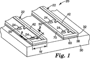
図1は、照明組立品20の一部分の斜視図を示す。照明組立品20には、1つ以上の長手の回路付きストリップ22が含まれる。各回路付きストリップ22は、複数のLED24を担持し、また放熱装置30に取り付けられている。本明細書で使用するとき、用語「放熱装置」は、一般に、発熱するLEDの表面などの熱い場所から離れてより冷たい熱質量部への熱の伝達を強化する、任意の装置又は素子を指すために使用されている。より冷たい熱質量部は、(周囲空気又は液体冷却材などの)流体又は(大きな金属ブロックなどの)固体とすることができる。放熱装置は、受動的にも能動的にもすることができ、固体もしくは流体の熱質量部だけを使用することも、又は相互に組み合わせて使用することもできる。放熱装置として、例えば、ヒートシンク、ヒートスプレッダー、ヒートパイプ、及び熱交換器が挙げられる。放熱装置は、熱伝達を強めるための放射フィン又は他の表面を含むことができる。
FIG. 1 shows a perspective view of a portion of a
放熱装置30は、熱伝導性及び導電性の材料で作製される。放熱装置30に好適な材料として、アルミニウムもしくは銅などの金属、又は例えば銅モリブデンを含む合金が挙げられる。代替実施形態では、非金属の熱伝導性材料が使用可能である。代表的な非金属材料は、ミネソタ州セントポール(Saint Paul, Minnesota)の3M社(3M Company)から3Mフレキシブルヒートシンク(3M Flexible Heat Sink)として入手可能な、グラファイトとシリコーンとの複合材料である。好ましくは、放熱装置30は、低い熱抵抗と低い電気固有抵抗とを有する。幾つかの実施形態では、放熱装置30は、約15〜20℃/Wの熱抵抗と、約1.7×10-8Ω・m以下の範囲の電気固有抵抗とを有する。
The
図2において最もよく見られるように、各回路付きストリップ22には、電気絶縁性の誘電基材32が含まれ、また、基材32は、その少なくとも第一の側36上に導電性の層34を、そしてその第二の側40上に導電性及び熱伝導性の層38を有する。図1及び図2に示されるように、基材32の第一の側36上の導電性の層34が、少なくとも1つの回路配線42を形成するようにパターン付けされ、一方、基材32の第二の側40上の層38は、パターン無しのままとすることができる。別の方法としては、層34は、LED24への動作電気接続のための電力配線及び信号配線が含まれる複数の回路配線を、基材32の第一の側36上に形成するようにパターン付けされてもよい。
As best seen in FIG. 2, each circuitized
電気絶縁性の誘電基材32は、様々な好適材料からなってもよく、例えば、デラウェア州ウィルミントン(Wilmington, Delaware)のデュポン(Du Pont)により製造されるカプトン(Kapton)ブランドのポリイミドなどのポリイミド、ポリエステル、ポリエチレンテレフタレート(PET)、(米国特許第5,882,774号(ジョンザ(Jonza)ら)及び同第5,808,794号(ウェバー(Weber)ら)にて開示されるような)多層光学フィルム、ポリカーボネート、ポリスルホン、又はFR4エポキシ複合材などが挙げられる。幾つかの実施形態では、基材32は、可撓性であることができる。基材32の第一及び第二の側36、40上の導電性及び熱伝導性の層34、38は、様々な好適材料、好ましくは、例えば銅、ニッケル、金、アルミニウム、スズ、鉛、クローム、及びこれらの組み合わせなどが含まれるがこれらに限定されない金属からなってもよい。基材32が可撓性である実施形態では、層34、38も可撓性であることが好ましい。その上に銅の導電性の層(複数)を有するポリイミドの絶縁性基材を備えた好適な可撓性材料は、ミネソタ州セントポール(Saint Paul, Minnesota)の3M社(3M Company)から入手可能な3M(登録商標)フレキシブル回路(Flexible Circuitry)である。
The electrically insulating
先に述べた多層光学フィルムは、交互するポリマー層を共押出しすることにより製造することができる。そのようなポリマー多層光学フィルムでは、ポリマー材料が、個別の層の構成に優勢的に又は独占的に使用される。そのようなフィルムは、大量製造プロセスに適合しており、大きいシート及びロール品で製造することができる。それらのフィルムは、異なる屈折率特性を有する個々のミクロ層を含むので、隣接ミクロ層間の界面で幾分かの光を反射する。ミクロ層は、所望の反射又は透過特性をフィルムに付与するために、複数の界面で反射された光が強め合う又は弱め合う干渉を受けるように、十分に薄い。紫外線、可視域、又は近赤外波長において光を反射するように設計された光学フィルムの場合、各ミクロ層は、一般に、光学的厚さ(すなわち、物理的厚さに屈折率を乗じたもの)が約1μm未満である。しかしながら、フィルムの外側表面における表面薄層、又はミクロ層のパケットを分離する、フィルム内に配置された保護境界層などのより厚い層も、含むことができる。 The multilayer optical film described above can be manufactured by coextrusion of alternating polymer layers. In such polymer multilayer optical films, the polymer material is used predominantly or exclusively in the construction of the individual layers. Such films are compatible with mass production processes and can be produced in large sheets and rolls. Because these films contain individual microlayers with different refractive index characteristics, they reflect some light at the interface between adjacent microlayers. The microlayer is thin enough that the light reflected at the multiple interfaces is subject to constructive or destructive interference to impart the desired reflective or transmissive properties to the film. For optical films designed to reflect light in the ultraviolet, visible, or near infrared wavelengths, each microlayer is generally optical thickness (ie, physical thickness multiplied by refractive index). ) Is less than about 1 μm. However, thicker layers can also be included, such as a skinned layer on the outer surface of the film, or a protective boundary layer disposed within the film that separates the microlayer packets.
多層光学フィルムの反射及び透過特性は、それぞれのミクロ層の屈折率の関数である。各ミクロ層は、フィルムの少なくとも局所的位置において、面内屈折率nx、ny、及びフィルムの厚さ方向軸に関連付けられる屈折率nzによって特徴づけることができる。これらの屈折率が、相互に直交するx軸、y軸、及びz軸それぞれに沿って偏光した光に対する、対象の材料の屈折率を表す。実際には、屈折率は、賢明な材料選択及び加工条件によって制御される。多層光学フィルムは、典型的には2つの交互するポリマーA、Bの数十又は数百の層を共押出した後、任意にその多層押出物を1つ以上の多層化ダイに通し、次に押出物を延伸して又は他の方法で配向して最終フィルムを形成することによって、製造することができる。得られたフィルムは、典型的には数十又は数百の個々のミクロ層で構成され、その厚さ及び屈折率は、可視又は近赤外などの所望のスペクトル領域において1以上の反射バンドをもたらすように調整される。妥当な数の層で高い反射率を達成するために、隣接ミクロ層は、好ましくは、少なくとも0.05の、x軸に沿って偏光した光に対する屈折率の差(Δnx)を示す。2つの直交する偏光に対して高反射率が望ましい場合には、隣接ミクロ層はまた、好ましくは、少なくとも0.05の、y軸に沿う偏光に対する屈折率の差(Δny)を示す。 The reflection and transmission properties of the multilayer optical film are a function of the refractive index of the respective microlayer. Each microlayer can be characterized by an in-plane refractive index nx , ny and a refractive index nz associated with the thickness axis of the film, at least at a local location in the film. These refractive indices represent the refractive index of the material of interest for light polarized along each of the x-, y-, and z-axes orthogonal to each other. In practice, the refractive index is controlled by sensible material selection and processing conditions. A multilayer optical film typically coextrudes tens or hundreds of layers of two alternating polymers A, B, and optionally passes the multilayer extrudate through one or more multilayering dies, then It can be made by stretching or otherwise orienting the extrudate to form the final film. The resulting film is typically composed of tens or hundreds of individual microlayers whose thickness and refractive index has one or more reflective bands in the desired spectral region, such as visible or near infrared. Adjusted to bring. In order to achieve high reflectivity with a reasonable number of layers, adjacent microlayers preferably exhibit a refractive index difference (Δn x ) for light polarized along the x-axis of at least 0.05. If the high reflectivity is desired for two orthogonal polarizations, adjacent microlayers also preferably exhibit at least 0.05, the difference in refractive index with respect to polarized light along the y-axis ([Delta] n y).
所望の場合、z軸に沿って偏光した光に対する隣接ミクロ層間の屈折率の差(Δnz)も、斜め入射光のp偏光成分に対する望ましい反射率特性を達成するように調整されることができる。説明を容易にするために、多層光学フィルム上の関心のあるいかなる点においても、x軸は、Δnxの大きさが最も大きくなるようにフィルム面内に配向されるものとする。したがって、Δnyの大きさは、Δnxの大きさに等しいか又はそれ未満(超過ではない)とすることができる。更に、差Δnx、Δny、Δnzを計算するに際して、どの材料層から始めるべきかという選定は、Δnxを負数にしないということを求めることにより決定される。言い換えれば、界面を形成する2層間の屈折率の差はΔnj=n1j−n2jであり、式中、j=x、y、又はz、及び層の表記1、2は、n1x≧n2x、すなわち、Δnx≧0となるように選定される。 If desired, the refractive index difference (Δn z ) between adjacent microlayers for light polarized along the z-axis can also be adjusted to achieve the desired reflectivity characteristics for the p-polarized component of obliquely incident light. . For ease of explanation, at any point of interest on a multilayer optical films, x-axis is assumed to magnitude of [Delta] n x are oriented in the largest so as to film plane. Thus, the magnitude of [Delta] n y can be equal to or less than the magnitude of [Delta] n x (not exceed). Furthermore, the difference [Delta] n x, [Delta] n y, when calculating the [Delta] n z, selected that should start from any material layer is determined by finding that not to [Delta] n x in negative. In other words, the difference in refractive index between the two layers forming the interface is Δn j = n 1j −n 2j , where j = x, y, or z, and the layer notations 1 and 2 are n 1x ≧ n 2x , that is, Δn x ≧ 0.
斜め入射角におけるp偏光の高い反射率を維持するために、ミクロ層間のz屈折率の不一致Δnzは、最も大きい面内屈折率の差Δnxより実質的に小さく制御して、Δnz≦0.5×Δnxのようにすることができる。より好ましくは、Δnz≦0.25×Δnxである。ゼロ又はほぼゼロの大きさのz屈折率の不一致が、p偏光に対する反射率が入射角の関数として一定又はほぼ一定である界面をミクロ層の間にもたらす。更に、z屈折率の不一致Δnzは、面内屈折率の差Δnxと比較して反対の極性を有するように、すなわち、Δnz<0であるように、制御することができる。この条件は、s偏光の場合と同様に、p偏光に対する反射率が、入射角の増加と共に増加する界面をもたらす。 To maintain high reflectivity of p-polarized light at oblique angles of incidence, mismatch [Delta] n z z-index of the microlayers may be substantially less control than the difference [Delta] n x the maximum in-plane refractive index, [Delta] n z ≦ it can be as 0.5 × Δn x. More preferably Δn z ≦ 0.25 × Δn x. A zero or nearly zero magnitude z-index mismatch results in an interface between the microlayers where the reflectivity for p-polarized light is constant or nearly constant as a function of incident angle. Furthermore, mismatch [Delta] n z z-index is to have the opposite polarity compared to the difference [Delta] n x of the in-plane refractive index, i.e., such that [Delta] n z <0, can be controlled. This condition results in an interface where the reflectivity for p-polarized light increases with increasing incident angle, as in the case of s-polarized light.
あるいは、多層光学フィルムは、ポリマーミクロ層の全てが本来等方性である、すなわち各々の層についてnx=ny=nzである、より簡単な構造を有することもできる。更に、コレステリック反射偏光子及びある種のブロックコポリマーなどの既知の自己組立周期構造を、本出願の目的のための多層光学フィルムと考えることができる。コレステリックミラーは、左旋性及び右旋性キラルピッチ要素の組み合わせを使用して作製することができる。 Alternatively, the multilayer optical film, all of the polymer microlayers are inherently isotropic, i.e., n x = n y = n z for each of the layers may also have a simpler structure. Furthermore, known self-assembled periodic structures such as cholesteric reflective polarizers and certain block copolymers can be considered multilayer optical films for the purposes of this application. Cholesteric mirrors can be made using a combination of levorotatory and dextrorotatory chiral pitch elements.
再び図2を参照すると、基材32は、基材32の第一の側36から第二の側40まで基材32を貫いて延びる、複数の貫通孔すなわちビア50を更に有する。各ビア50は、その中にLED24を受け入れるように構成される。ビア50は、使用される製造プロセス及び材料に依存して、当該技術分野において既知のように、絶縁性基材32を貫く化学的エッチング、プラズマエッチング、レーザーミリング、又はパンチで加工することができる。
Referring again to FIG. 2, the
図面群において、回路付きストリップ22は、単一列のビアを収容するのに十分な幅Wを有する。別の実施形態では、回路付きストリップ22の幅Wは、2列以上のビアを収容してもよい。LED24は、特定のライティング用途並びにその関連付けられた明るさ及び解像度条件に依存して、3mm〜15mmの範囲のLEDからLEDへの間隔(ピッチ)で、所与の回路付きストリップ22に沿って配置されてもよい。非常に高い解像度及び/又は明るさが要求される用途では、所望のピッチは、3mm未満であってもよい。解像度及び/又は明るさの条件が低い他の用途では、所望のピッチは、15mm超過であってもよい。
In the drawings, the
ビア50は、組立中にLED24を配置するのに便利な位置合わせ点という利点をもたらす。好ましくは、ビア50は、基材32の第二の側40上に設けられた導電性及び熱伝導性の層38を貫いて延びることがなく、製造プロセス中にビア50内に置かれたLED24が、層38に取り付けできるようになっている。導電性及び熱伝導性の層38は、例えば、LED24への電気接続を作ること、LED24から下に存在する放熱装置30への直接的な熱通路を提供すること、LED24から横方向へ熱を拡散すること、及び他のシステムへの電気接続を提供することなどの、目的の組み合わせに役立つことができる。図1及び図2の照明組立品20では、図示されるLED24は、LED24の基部52上に1つの電気接点とLED24の反対(頂)面上に別の電気接点とを有するタイプのものである。各LED24の基部52上の接点は、基材32の第二の側40上の層38に電気的及び熱的に接続され、一方、各LED24の頂部上の接点は、LED24から回路配線42上のボンディングパッド56まで延びるワイヤボンド54によって、基材32の第一の側36上の回路配線42に電気接続される。
Via 50 provides the advantage of a convenient alignment point for positioning
LED24を基材32の第二の側40上の熱伝導性及び導電性の層38に取り付けるのに使用可能な取り付け方法の中には、熱伝導性及び導電性の接着剤、はんだリフロー、(LEDダイが適切な裏側金属被覆を有する場合)熱音波接着、並びにAu/Sn共晶結合がある。はんだは通常、接着剤より低い熱抵抗を有するが、全てのLED24が、はんだ付け可能な基部の金属被覆を有するわけではない。はんだ取り付けはまた、溶融はんだの表面張力がプロセス中にLED24を整列させるので、LED24の自己位置合わせという利点を有する。しかしながら、幾つかのLEDは、はんだのリフロー温度に敏感なことがあり、接着剤がより適切となる。
Among the attachment methods that can be used to attach the
LED24は、少なくとも幾つかのビア50の中に配置される。ビア50の幾つかは、任意に、LED24が装着されないままでもよい。例えば、幾つかの実施形態では、1つ置きのビアを未装着で残すことができる。未装着のビア50は、幾つかの目的のために有用である。回路付きストリップ内のビアの幾つかにLEDを装着した後、あるLEDが欠陥品であるとテスト中に判明した場合、交換のLEDを、欠陥LEDの隣の未装着のビアの中に取り付けてもよい。未装着のビアはまた、回路付きストリップ22への適切な電力及び信号接続を作るために、又は組立品の他の要素との位置合わせのための位置合わせ点として、使用することができる。
The
LED24が取り付けられた回路付きストリップ22は、第一の側36が放熱装置30から離れ、また導電性及び熱伝導性の層38が放熱装置30に隣接するように、放熱装置30の上に配置される。したがって、基材32の第一の側36上の回路配線42は、基材32によって導電性の層38及び放熱装置30から電気的に絶縁される。基材32の第二の側40上の導電性及び熱伝導性の層38は、好ましくは、図1及び図2において固着層60として示される導電性及び熱伝導性の固着剤を使用して、放熱装置30の上に実装される。層38を放熱装置30に取り付けるのに使用可能な取り付け方法の中には、熱伝導性及び導電性の接着剤又ははんだがある。したがって、放熱装置30は、照明組立品20の熱制御システムの能動素子であるのに加えて、照明組立品20の電気回路の能動素子でもある。例えば、放熱装置30は、回路付きストリップ22内のLED24のそれぞれに対して共通の電気接地を提供することができる。更に、放熱装置30が良好な導電率を有する材料で構成されるとき、低い電圧降下での均一な電流分布及びEMI遮蔽を含む追加効果が、有益にもたらされる。
The
基材32の第二の側40上の層38及び放熱装置30は、両方とも金属とすることができ、固着されるべき金属表面の少なくとも1つにはんだを付着させて、次に層38及び放熱装置30の金属表面を互いにはんだ付けすることによって、回路付きストリップ22を放熱装置30上に実装させることができる。好適なはんだ付け方法には、リフローはんだ付け及びフローはんだ付けが含まれる。はんだ付けはまた、はんだペーストを使用し、加熱したニップ又はスタンプで回路付きストリップ22を金属の放熱装置30に積み重ねて、実施されてもよい。回路付きストリップ22と放熱装置30の間の固着は、回路付きストリップ22の全面積にわたって広がってもよく、又は回路付きストリップの一部分だけを覆ってもよい。ある場合には、LEDと放熱装置との間の照明組立品の層又は構成要素が、LED24と放熱装置30との間に直接的な熱通路をもたらすことが望ましい。ある場合には、回路付きストリップ22は、回路付きストリップ22にLED24を装着する前に、放熱装置30の上に実装することができる。
The
非パッケージ化LEDダイがビアの装着に使用される場合、LED24は通常、高さが公称250マイクロメートルであり、絶縁性基材32は、厚さが25〜50マイクロメートルの範囲であり、導電性の層34、36の厚さは、17〜34マイクロメートルの範囲であるが、LED24の電力条件に基づいて、その範囲よりいくらか変化させることができる。ボンディングパッド56における良好なワイヤボンディングを容易にするために、ボンディングパッド56は、ニッケル及び金の表面金属被覆を含むことができる。ビア50は、化学的にエッチングされたビアにおいて典型的であるように、傾斜側壁62を有するとして示されている。しかしながら、プラズマエッチング又はレーザーミリングされたビアは、実質的に垂直の側壁を有してもよい。
When an unpackaged LED die is used for via mounting, the
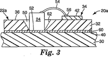
図3は、照明組立品20に類似する照明組立品20aの概略断面図であるが、ストリップ22が回路付きストリップ22aに置き換えられている。図3の回路付きストリップ22aは、基材32の第二の側40上の導電性及び熱伝導性の層38が省略されたという点で、図2のストリップ22と異なる。図3の実施形態では、回路付きストリップ22aは、ビア50の全て又は一部にLED24を装着する前に、放熱装置30の上に実装される。ビア50にLED24を装着すると、各LED24の基部52が、放熱装置30に直接的に電気的及び熱的に接続され、一方、各LED24の頂部上の接点が、LED24から回路配線42上のボンディングパッド56まで延びるワイヤボンド54によって、回路配線42に電気接続される。基材の第二の側40上に金属層がない場合、回路付きストリップ22aは、いかなる好適な方法によって取り付けられてもよく、それには熱伝導性及び導電性の接着剤、又ははんだが含まれる。基材32を放熱装置30に取り付けるのに接着剤が使用される場合でさえ、LED24と放熱装置30との間の熱伝導率を改善するために、LED24と放熱装置30との間に、はんだ固着も形成することができる。したがって、放熱装置30は、照明組立品20の能動的な熱及び電気素子である。
FIG. 3 is a schematic cross-sectional view of a
図4及び図5はそれぞれ、追加の照明組立品20b、20cの概略断面図であって、代わりの回路付きストリップ22b、22cを利用している。図4及び図5では、ワイヤボンディングされたLED24aは、両方の電気接点パッドを、図1〜図3のワイヤボンディングされたLED24のようにダイオードの反対側上にではなく、LEDの同一側上に有する。図4の回路付きストリップ22bの構成は、図2のストリップ22と類似しており、LED24aが、ビア50の中に配置され、熱伝導性の層60によって層38に熱的に接続されている。層60は、例えば接着剤、はんだ、熱音波接着、又はAu/Sn共晶結合を含んでもよい。図5の回路付きストリップ22cの構成は、図3のストリップ22aと類似しており、LED24aが、ビア50の中に配置され、熱伝導性の接着剤又ははんだ層60によって、放熱装置30に熱的に接続されている。図4及び図5の照明組立品では、LED24aには、放熱装置30への直接の熱通路が備わっているが、放熱装置30は、照明組立品20の能動的な電気素子ではない。
4 and 5 are schematic cross-sectional views of
図6及び図7は、追加の照明組立品20dを示すが、これは、放熱装置30a、30bの組み合わせの上に配置された、代わりの回路付きストリップ22dを利用している。各回路付きストリップ22dは、電気絶縁性の誘電基材32を含み、また、基材32は、基材32の第一の側36から第二の側40まで基材32を貫いて延びる複数の貫通孔すなわちビア50を有する。各ビア50は、その中にLED24bを受け入れるように構成される。導電性及び熱伝導性の層38dが、第二の側40上に配置され、ビア50全体に広がる。導電性及び熱伝導性の層38dは、複数の別個の区分64を形成するようにパターン付けされて、それぞれのビア50が区分64の1つに関連付けられる。
FIGS. 6 and 7 show an
層38dの区分64は、例えば、LEDへの電気接続を作ること、LEDから下に存在する放熱装置30a、30bへの熱通路を提供すること、LEDから横方向へ熱を拡散すること、及び他のシステムへの電気接続を提供することなどの、目的の組み合わせに役立つことができる。図6及び図7の照明組立品20dでは、図示されるLED24bは、LEDの基部52上に1つの電気接点とLEDの反対(頂)面上に別の電気接点とを有するタイプのものである。各LEDの基部52上の接点が、層38dの関連付けられた区分64に電気的及び熱的に接続され、一方、各LEDの頂部上の接点が、LED24bから、基材32を貫いて延びる充填されたビア66まで延びるワイヤボンド54によって、隣接区分64に電気接続される。別の実施形態では、ビア66は充填されていなくてもよく、ワイヤボンド54は、隣接区分64に直接的に接続することができる。層38dの別個の区分64によって、LEDの直列接続が可能となるが、これは、ある種の用途で望ましいことがある。他の実施形態に関し先に説明したように、層38dは、金属とすることができ、熱伝導性及び導電性の接着剤、はんだリフロー、(LEDダイが適切な裏側金属被覆を有する場合)熱音波接着、及びAu/Sn共晶結合を含む取り付け方法によって、LED24bに取り付けることができる。
回路付きストリップ22dのそれぞれについて、層38dの区分64がそれぞれ、関連付けられた第一の放熱装置30aの1つに直接的に固着される。第一の放熱装置30aは、ストリップ22dの幅W2より広い幅W1を有し、ヒートスプレッダーとして機能して、関連付けられたLEDにより発生された熱を第二の放熱装置30bに伝達する助けをする。第二の放熱装置30bには、フィン68などの機構が含まれて、組立品20dからの熱放散の助けをすることができる。
For each
図示される実施形態では、各第一の放熱装置30aは、層38dの関連付けられた区分64に電気的及び熱的に接続されるが、第二の放熱装置30bからは電気的に隔離される。層38d及び第一の放熱装置30aが金属であるとき、各区分64及び関連付けられた第一の放熱装置30aは、固着されるべき金属表面の少なくとも1つにはんだを付着させて、次に層38d及び第一の放熱装置30aの金属表面を互いにはんだ付けすることによって、熱的及び電気的に固着することができる。はんだ付けはまた、はんだペーストを使用し、加熱したニップ又はスタンプで回路付きストリップ22dの区分64を金属の第一の放熱装置30aに積み重ねて、実施されてもよい。第一の放熱装置30aは、熱伝導性であるが電気絶縁性の層69によって、第二の放熱装置30bから電気的に分離される。層69の材料は、例えば、ミネソタ州セントポール(Saint Paul, Minnesota)の3M社(3M Company)から3M2810として入手可能なもののような、窒化ホウ素が充填されたポリマーなどの熱伝導性接着剤とすることができる。
In the illustrated embodiment, each first
図1及び図6の回路付きストリップは、例えば基材にスリットを入れることにより形成されるような、真直ぐの側縁部70を有するとして示されている。別の実施形態では、回路付きストリップは、例えば打ち抜き又はエッチング加工により形成される、複雑な側縁部を有してもよい。図8において、複雑な側縁部70aを有する代表的な回路付きストリップ22eが、上面すなわち平面図で示される。ストリップ22eには、複数の比較的狭い首部領域74により分離された、複数の比較的広い拡大領域72が含まれる。複数の電力及び信号の伝導配線42aが、基材32の第一の表面上に設けられている。拡大領域72のそれぞれには、LED(図示せず)を受け入れるためのビア50と、LED及び他の電気システムへの電気接続を作るためのボンディングパッド56とが含まれる。
The circuitized strip of FIGS. 1 and 6 is shown as having straight side edges 70, such as formed by slitting the substrate. In another embodiment, the circuitized strip may have complex side edges formed, for example, by stamping or etching. In FIG. 8, a typical
図1〜図8の回路付きストリップは、絶縁性の誘電基材のシート又はウェブから製造することができる。図9に、図8の回路付きストリップ22eを製造するための1つの方法が示される。絶縁性の誘電基材32のウェブ又はシート80が、金属被覆されて、複数の伝導配線42aを上に有するようにパターン付けされる。ウェブ又はシート80は、次に、スリットされる、打ち抜かれる、ジッパー状の穿孔が設けられて引き裂かれる、又はエッチングされて、個々の回路付きストリップ22eに分離される。図9において、複雑な側縁部70aの形状によって、基材32の不使用領域が、どのようにして有利に最小限になるかを見ることができる。回路付きストリップ22eが分離された後で、LEDは、先に説明されたようにビアの幾つか又は全ての中へ実装することにより回路付きストリップ22eに取り付けることができ、ストリップ22eは所望の配列及び間隔で放熱装置上に実装される。
The circuitized strips of FIGS. 1-8 can be made from a sheet or web of insulating dielectric substrate. FIG. 9 illustrates one method for manufacturing the
照明組立品の実施形態の全てにおいて、開示された回路付きストリップ、もしくはLED、又は両方は、照明組立品上の他の光学デバイス、フィルム、又は他の要素と組み合わせることができる。そのようなデバイス、フィルム、又は他の要素は、例えば、光を吸収するマスキング構成要素、反射性の高い材料、及び封入材、並びに蛍光体を含むことができる。 In all lighting assembly embodiments, the disclosed circuitized strips or LEDs, or both, can be combined with other optical devices, films, or other elements on the lighting assembly. Such devices, films, or other elements can include, for example, masking components that absorb light, highly reflective materials, and encapsulants, and phosphors.
封入材は、回路付きストリップをウェブ80から分離する前又は後で、LEDの全て又は幾つかに直接的に適用することができる。封入材は、LEDを個々に、又は2つ以上のLEDのグループとして覆うことができる。封入材の形状及び位置が、所望の導光効果又は光抽出効果をもたらすことができる。封入材は、LEDの最終所望形状を形成することができ、又は後に別の封入材の層で覆われてもよい。当初の封入材層を別の封入材層で覆うことによって、LEDで装填された回路付きストリップが容易に取り扱われている間に、より高価で高屈折率の、硬化が遅い封入材及び封入材の汎用形状の生成が可能となり、後刻、より複雑な封入材の形状が適用可能となる。封入材の形状は、屈折と反射との組み合わせを通して、光を分布させることができる。封入材はまた、他の光学構成要素と協同して、所望の光出力特性を作り出すことができる。他の光学素子は、照明組立品の所望の光学特性に依存して、回路付きストリップの間に、LEDを覆って、又はLEDの間に適用可能である。
The encapsulant can be applied directly to all or some of the LEDs before or after separating the strip with circuit from the
図6の組立品20dは、隣接する回路付きストリップ22dの第一の放熱装置30aの間に配置された光学フィルム層82を示す。代替実施形態では、層80にLEDの位置で開口が設けられている場合、層82は、第一の放熱装置30aの上に、又は回路付きストリップの上全体に広がることができる。図7では、任意の封入材84が、基材32の第一の側36を覆って広がっているのが示される。光学フィルム層82及び封入材84は、本明細書で説明された照明組立品のいずれとも併せて使用可能である。
The
好ましい実施形態の説明の目的のために、特定の実施形態を本明細書において例示し記述したが、同じ目的を達成すると予測される種々多様な代替及び/又は同等の実施が、本発明の範囲を逸脱することなく、図示及び説明された特定の実施形態に置き換わり得ることを、当業者は理解するであろう。化学技術、機械技術、電気機械技術、及び電気技術の当業者は、本発明が多種広範な実施形態で実行できることを、容易に理解するであろう。本出願は、本明細書で説明された好ましい実施形態のいかなる翻案又は変形をも包含すべく意図されている。したがって、本発明が請求項及びその等価物によってのみ限定されることを、明示的に意図するものである。 While specific embodiments have been illustrated and described herein for the purpose of illustrating the preferred embodiments, various alternative and / or equivalent implementations that are expected to achieve the same objectives are within the scope of the present invention. Those skilled in the art will appreciate that the specific embodiments shown and described may be substituted without departing from the invention. Those skilled in the chemical, mechanical, electromechanical, and electrical arts will readily appreciate that the present invention can be implemented in a wide variety of embodiments. This application is intended to cover any adaptations or variations of the preferred embodiments described herein. Therefore, it is manifestly intended that this invention be limited only by the claims and the equivalents thereof.
Claims (3)
前記放熱部材上に間隔のある関係で配置された複数の回路付きストリップであって、そのようなストリップのそれぞれが、電気絶縁性の基材と、その基材の第一の側上の少なくとも1つの回路配線及びその基材の第二の側上の導電性及び熱伝導性の層とを有しており、前記回路配線の少なくとも1つは前記基材の第二の側から電気的に絶縁されており、また、前記回路付きストリップは、前記基材の第一の側から第二の側まで延びる複数のビアを有している可撓性の回路付きストリップと、
前記複数のビア内に配置された複数のLEDであって、前記LEDのそれぞれは、前記基材の第二の側上の導電性及び熱伝導性の層の上に配置され、かつ前記基材の第一の側上の少なくとも1つの回路配線に電気的に接続されているLEDと
を含んでなる照明組立品。A heat dissipating member;
A plurality of circuitized strips disposed in spaced relation on the heat dissipating member, each such strip comprising an electrically insulating substrate and at least one on a first side of the substrate. And a conductive and thermally conductive layer on the second side of the substrate, wherein at least one of the circuit wires is electrically isolated from the second side of the substrate. And the strip with circuit is a flexible strip with circuit having a plurality of vias extending from a first side to a second side of the substrate;
A plurality of LEDs disposed in the plurality of vias, each of the LEDs disposed on a conductive and thermally conductive layer on a second side of the substrate; and And an LED electrically connected to at least one circuit wiring on the first side of the lighting assembly.
前記複数のビアの少なくとも1つに配置されたLEDと、
前記可撓性の回路の第二の側に近接して配置された導電性の放熱部材と
を含み、かつ、その際、
前記LEDは、前記放熱部材及び前記少なくとも1つの回路配線の両方に電気的に接続されている、照明組立品。An electrically insulating substrate and at least one circuit wiring on a first side of the substrate and a plurality of vias extending through the substrate from a first side to a second side of the substrate; A flexible circuit comprising:
An LED disposed in at least one of the plurality of vias;
A conductive heat dissipating member disposed proximate to the second side of the flexible circuit, and
The LED is an illumination assembly that is electrically connected to both the heat dissipation member and the at least one circuit wiring.
電気絶縁性の可撓性基材を提供することと、
前記電気絶縁性の基材の上に複数の回路配線を提供することと、
前記電気絶縁性の基材に複数列のビアを設けるとともに、それらのビアの各列には少なくとも1つの関連付けられた回路配線を備えることと、
前記基材を複数のストリップに分離するとともに、各ストリップに前記複数列のビアの1つと、関連付けられた回路配線とを含ませることと、
各ストリップの少なくとも1つのビアにLEDを装着して、そのLEDを前記関連付けられた回路配線に電気的に接続することと、
前記複数のストリップの少なくとも2つをヒートシンク上に配置してLEDのアレイを形成し、各ストリップのLEDを前記ヒートシンクに電気的に接続することと
を含んでなる照明組立品の製造方法。A method of manufacturing a lighting assembly comprising:
Providing an electrically insulating flexible substrate;
Providing a plurality of circuit wirings on the electrically insulating substrate;
Providing a plurality of rows of vias in the electrically insulating substrate, each row of vias having at least one associated circuit wiring;
Separating the substrate into a plurality of strips, each strip including one of the plurality of rows of vias and associated circuit wiring;
Mounting an LED in at least one via of each strip and electrically connecting the LED to the associated circuit wiring;
Disposing at least two of the plurality of strips on a heat sink to form an array of LEDs, and electrically connecting the LEDs of each strip to the heat sink.
Applications Claiming Priority (3)
| Application Number | Priority Date | Filing Date | Title |
|---|---|---|---|
| US10/982,651 US7303315B2 (en) | 2004-11-05 | 2004-11-05 | Illumination assembly using circuitized strips |
| US10/982,651 | 2004-11-05 | ||
| PCT/US2005/034501 WO2006052330A2 (en) | 2004-11-05 | 2005-09-27 | Illumination assembly with circuitized strips |
Publications (3)
| Publication Number | Publication Date |
|---|---|
| JP2008519419A JP2008519419A (en) | 2008-06-05 |
| JP2008519419A5 JP2008519419A5 (en) | 2008-11-13 |
| JP4763709B2 true JP4763709B2 (en) | 2011-08-31 |
Family
ID=36118083
Family Applications (1)
| Application Number | Title | Priority Date | Filing Date |
|---|---|---|---|
| JP2007540306A Expired - Fee Related JP4763709B2 (en) | 2004-11-05 | 2005-09-27 | Lighting assembly using strip with circuit |
Country Status (6)
| Country | Link |
|---|---|
| US (1) | US7303315B2 (en) |
| JP (1) | JP4763709B2 (en) |
| KR (1) | KR101206209B1 (en) |
| CN (1) | CN100517779C (en) |
| TW (1) | TW200628725A (en) |
| WO (1) | WO2006052330A2 (en) |
Families Citing this family (122)
| Publication number | Priority date | Publication date | Assignee | Title |
|---|---|---|---|---|
| US10340424B2 (en) | 2002-08-30 | 2019-07-02 | GE Lighting Solutions, LLC | Light emitting diode component |
| US7145125B2 (en) | 2003-06-23 | 2006-12-05 | Advanced Optical Technologies, Llc | Integrating chamber cone light using LED sources |
| US7521667B2 (en) | 2003-06-23 | 2009-04-21 | Advanced Optical Technologies, Llc | Intelligent solid state lighting |
| US7341199B2 (en) * | 2003-11-12 | 2008-03-11 | Siemens Energy & Automation, Inc. | Material handling system with dynamic source tagging |
| WO2005060309A2 (en) * | 2003-12-11 | 2005-06-30 | Color Kinetics Incorporated | Thermal management methods and apparatus for lighting devices |
| CN100483024C (en) * | 2004-11-09 | 2009-04-29 | 李学霖 | Heat radiation structure of LED lamp |
| US7285802B2 (en) * | 2004-12-21 | 2007-10-23 | 3M Innovative Properties Company | Illumination assembly and method of making same |
| US9070850B2 (en) | 2007-10-31 | 2015-06-30 | Cree, Inc. | Light emitting diode package and method for fabricating same |
| GB2422249A (en) * | 2005-01-15 | 2006-07-19 | Robert John Morse | Power substrate |
| US7121687B2 (en) * | 2005-01-25 | 2006-10-17 | Osram Sylvania Inc. | Automotive LED bulb |
| JP4241658B2 (en) * | 2005-04-14 | 2009-03-18 | シチズン電子株式会社 | Light emitting diode light source unit and light emitting diode light source formed using the same |
| JP4410721B2 (en) * | 2005-05-02 | 2010-02-03 | シチズン電子株式会社 | Bulb type LED light source |
| US7703951B2 (en) * | 2005-05-23 | 2010-04-27 | Philips Solid-State Lighting Solutions, Inc. | Modular LED-based lighting fixtures having socket engagement features |
| US7766518B2 (en) * | 2005-05-23 | 2010-08-03 | Philips Solid-State Lighting Solutions, Inc. | LED-based light-generating modules for socket engagement, and methods of assembling, installing and removing same |
| AU2006249979B2 (en) * | 2005-05-23 | 2011-08-25 | Signify North America Corporation | Modular led lighting apparatus for socket engagement |
| KR100764380B1 (en) * | 2005-12-16 | 2007-10-08 | 삼성전기주식회사 | Slim type back light unit |
| US8044412B2 (en) | 2006-01-20 | 2011-10-25 | Taiwan Semiconductor Manufacturing Company, Ltd | Package for a light emitting element |
| JP4997584B2 (en) * | 2006-01-26 | 2012-08-08 | Nltテクノロジー株式会社 | Liquid crystal display |
| JP2009525614A (en) * | 2006-01-31 | 2009-07-09 | スリーエム イノベイティブ プロパティズ カンパニー | LED lighting assembly having compliant foil structure |
| WO2007097281A1 (en) * | 2006-02-22 | 2007-08-30 | Stanley Electric Co., Ltd. | Illuminating apparatus |
| US20070211492A1 (en) * | 2006-03-09 | 2007-09-13 | Gigno Technology Co., Ltd. | Backlight module and driving circuit board of light emitting diodes |
| TWI289947B (en) * | 2006-03-17 | 2007-11-11 | Ind Tech Res Inst | Bendable solid state planar light source, a flexible substrate therefor, and a manufacturing method therewith |
| US7710045B2 (en) * | 2006-03-17 | 2010-05-04 | 3M Innovative Properties Company | Illumination assembly with enhanced thermal conductivity |
| US7675145B2 (en) * | 2006-03-28 | 2010-03-09 | Cree Hong Kong Limited | Apparatus, system and method for use in mounting electronic elements |
| US20070252161A1 (en) * | 2006-03-31 | 2007-11-01 | 3M Innovative Properties Company | Led mounting structures |
| US7806574B2 (en) * | 2006-04-16 | 2010-10-05 | Albeo Technologies, Inc. | Thermal management of LED-based lighting systems |
| US20070247851A1 (en) * | 2006-04-21 | 2007-10-25 | Villard Russel G | Light Emitting Diode Lighting Package With Improved Heat Sink |
| US8748915B2 (en) | 2006-04-24 | 2014-06-10 | Cree Hong Kong Limited | Emitter package with angled or vertical LED |
| JP4944948B2 (en) * | 2006-05-05 | 2012-06-06 | クリー インコーポレイテッド | Lighting device |
| US20080012035A1 (en) * | 2006-07-11 | 2008-01-17 | Bily Wang | LED chip package structure and method for manufacturing the same |
| US8735920B2 (en) | 2006-07-31 | 2014-05-27 | Cree, Inc. | Light emitting diode package with optical element |
| KR101318372B1 (en) * | 2006-08-03 | 2013-10-16 | 삼성디스플레이 주식회사 | Illuminant unit, backlight assembly and display apparatus having the same |
| DE102007004303A1 (en) * | 2006-08-04 | 2008-02-07 | Osram Opto Semiconductors Gmbh | Thin-film semiconductor device and device composite |
| TWI340010B (en) * | 2006-08-04 | 2011-04-01 | Everlight Electronics Co Ltd | Circuit board with cooling functionality |
| US8367945B2 (en) * | 2006-08-16 | 2013-02-05 | Cree Huizhou Opto Limited | Apparatus, system and method for use in mounting electronic elements |
| JP2008053380A (en) * | 2006-08-23 | 2008-03-06 | Hamamatsu Photonics Kk | Laser device |
| US8362603B2 (en) * | 2006-09-14 | 2013-01-29 | Luminus Devices, Inc. | Flexible circuit light-emitting structures |
| US8581393B2 (en) * | 2006-09-21 | 2013-11-12 | 3M Innovative Properties Company | Thermally conductive LED assembly |
| US20080074881A1 (en) * | 2006-09-25 | 2008-03-27 | Been-Yu Liaw | Backlight module |
| US7794114B2 (en) * | 2006-10-11 | 2010-09-14 | Cree, Inc. | Methods and apparatus for improved heat spreading in solid state lighting systems |
| US20080112162A1 (en) * | 2006-11-09 | 2008-05-15 | Topson Optoelectronics Semi-Conductor Co., Ltd. | Backlight Structure Having Embedded LEDs and Fabrication Method Thereof |
| CN100423257C (en) * | 2006-12-20 | 2008-10-01 | 黄虎钧 | Lighting stick with LBD wafer |
| DE102007004304A1 (en) | 2007-01-29 | 2008-07-31 | Osram Opto Semiconductors Gmbh | Thin-film light emitting diode chip, has layer stack made of primary radiation surfaces lying opposite to each other so that thin-film light emitting diode chip has two primary radiation directions |
| US7806560B2 (en) * | 2007-01-31 | 2010-10-05 | 3M Innovative Properties Company | LED illumination assembly with compliant foil construction |
| US9711703B2 (en) | 2007-02-12 | 2017-07-18 | Cree Huizhou Opto Limited | Apparatus, system and method for use in mounting electronic elements |
| EP2127486B1 (en) * | 2007-02-26 | 2012-06-06 | Philips Intellectual Property & Standards GmbH | Driving a lighting device |
| US7841741B2 (en) * | 2007-04-02 | 2010-11-30 | Endicott Interconnect Technologies, Inc. | LED lighting assembly and lamp utilizing same |
| US7898811B2 (en) * | 2007-04-10 | 2011-03-01 | Raled, Inc. | Thermal management of LEDs on a printed circuit board and associated methods |
| US7535030B2 (en) * | 2007-05-22 | 2009-05-19 | Hsiang-Chou Lin | LED lamp with exposed heat-conductive fins |
| EP1998101B2 (en) | 2007-05-30 | 2019-09-25 | OSRAM GmbH | Lighting device |
| WO2009000282A1 (en) * | 2007-06-22 | 2008-12-31 | Lioris B.V. | High voltage led lighting system |
| JP5431688B2 (en) * | 2007-06-29 | 2014-03-05 | ソウル セミコンダクター カンパニー リミテッド | Multi LED package |
| US7922354B2 (en) * | 2007-08-13 | 2011-04-12 | Everhart Robert L | Solid-state lighting fixtures |
| US20090096347A1 (en) * | 2007-10-11 | 2009-04-16 | Xu Chao-Feng | LED Flat Light and A Manufacturing Method Thereof |
| US8866169B2 (en) | 2007-10-31 | 2014-10-21 | Cree, Inc. | LED package with increased feature sizes |
| US10256385B2 (en) | 2007-10-31 | 2019-04-09 | Cree, Inc. | Light emitting die (LED) packages and related methods |
| DE102007055133A1 (en) * | 2007-11-19 | 2009-05-20 | Osram Gesellschaft mit beschränkter Haftung | Lighting device with a heat sink |
| KR101015818B1 (en) * | 2007-11-21 | 2011-02-22 | 크루셜텍 (주) | Camera flash module and portable electronic device having it |
| US20090218588A1 (en) * | 2007-12-06 | 2009-09-03 | Paul Panaccione | Chip-scale packaged light-emitting devices |
| CN101451696A (en) * | 2007-12-07 | 2009-06-10 | 富准精密工业(深圳)有限公司 | LED lamp |
| CN101556032B (en) * | 2008-04-09 | 2010-09-29 | 富准精密工业(深圳)有限公司 | Light emitting diode lamp |
| CN101572990B (en) * | 2008-04-28 | 2012-12-19 | 鸿富锦精密工业(深圳)有限公司 | Circuit board primitive plate |
| US7845829B2 (en) * | 2008-05-20 | 2010-12-07 | Abl Ip Holding Llc | Enclosures for LED circuit boards |
| US8177392B2 (en) * | 2008-05-29 | 2012-05-15 | Norm Tarko | Light strip including a core layer of insulating material receiving spaced apart light emitting diodes |
| JP5236366B2 (en) * | 2008-07-01 | 2013-07-17 | ミネベア株式会社 | Linear light source device and planar illumination device |
| US9022612B2 (en) * | 2008-08-07 | 2015-05-05 | Mag Instrument, Inc. | LED module |
| US20100038670A1 (en) * | 2008-08-18 | 2010-02-18 | Luminus Devices, Inc. | Illumination assembly including chip-scale packaged light-emitting device |
| US9076951B2 (en) | 2008-08-26 | 2015-07-07 | Albeo Technologies, Inc. | Methods of integrating LED chips with heat sinks, and LED-based lighting assemblies made thereby |
| US8058659B2 (en) | 2008-08-26 | 2011-11-15 | Albeo Technologies, Inc. | LED chip-based lighting products and methods of building |
| US8981629B2 (en) | 2008-08-26 | 2015-03-17 | Albeo Technologies, Inc. | Methods of integrating LED chips with heat sinks, and LED-based lighting assemblies made thereby |
| GB2464668A (en) * | 2008-10-20 | 2010-04-28 | Sensitive Electronic Co Ltd | Thin light emitting diode circuit substrate and lamp strip |
| KR100902631B1 (en) * | 2008-10-24 | 2009-06-12 | 현대통신 주식회사 | Circle type led lighting flood lamp using nano spreader |
| US8791471B2 (en) * | 2008-11-07 | 2014-07-29 | Cree Hong Kong Limited | Multi-chip light emitting diode modules |
| DE102008056923A1 (en) * | 2008-11-12 | 2010-05-27 | Osram Gesellschaft mit beschränkter Haftung | Lighting device with two printed circuit boards |
| US20100149805A1 (en) * | 2008-12-17 | 2010-06-17 | Fridy Joseph | Led lighting laminate with integrated cooling |
| TW201025675A (en) * | 2008-12-31 | 2010-07-01 | Jess Link Products Co Ltd | Light emitting diode light strip and method of making the same |
| US20110037083A1 (en) * | 2009-01-14 | 2011-02-17 | Alex Chi Keung Chan | Led package with contrasting face |
| US8368112B2 (en) | 2009-01-14 | 2013-02-05 | Cree Huizhou Opto Limited | Aligned multiple emitter package |
| US20100188860A1 (en) * | 2009-01-28 | 2010-07-29 | Been-Yu Liaw | Lotus blossom heat dissipating device |
| JP2011009298A (en) * | 2009-06-23 | 2011-01-13 | Citizen Electronics Co Ltd | Light-emitting diode light source device |
| KR20110003792A (en) * | 2009-07-06 | 2011-01-13 | 주식회사 디지아이 | Method for manufacturing printed circuit board of color |
| TW201103170A (en) * | 2009-07-08 | 2011-01-16 | Paragon Sc Lighting Tech Co | LED package structure with concave area for positioning heat-conducting substance and method for manufacturing the same |
| JP4746692B2 (en) * | 2009-07-29 | 2011-08-10 | 株式会社タムラ製作所 | LED lighting device for visible light communication |
| US20110054263A1 (en) * | 2009-08-28 | 2011-03-03 | Jim-Son Chou | Replaceable LED illumination assembly for medical instruments |
| US8593040B2 (en) | 2009-10-02 | 2013-11-26 | Ge Lighting Solutions Llc | LED lamp with surface area enhancing fins |
| TWM379006U (en) * | 2009-10-22 | 2010-04-21 | Jia-hao ZHANG | LED light bar |
| US8408627B2 (en) * | 2009-12-15 | 2013-04-02 | 3M Innovative Properties Company | Pick up truck, rail cap assembly with lighting system and method of use |
| US10240772B2 (en) * | 2010-04-02 | 2019-03-26 | GE Lighting Solutions, LLC | Lightweight heat sinks and LED lamps employing same |
| JP5920213B2 (en) * | 2010-04-13 | 2016-05-18 | 宇部興産株式会社 | LED heat dissipation board |
| EP2561265A4 (en) * | 2010-04-21 | 2015-03-11 | Cooper Technologies Co | Expandable led board architecture |
| JP5537295B2 (en) * | 2010-07-05 | 2014-07-02 | パナソニック株式会社 | Light emitting element mounting wiring pattern, light emitting element mounting wiring board having light emitting element mounting wiring pattern, light emitting module using light emitting element mounting wiring board, and lighting fixture equipped with light emitting module |
| US9548286B2 (en) | 2010-08-09 | 2017-01-17 | Micron Technology, Inc. | Solid state lights with thermal control elements |
| US9035329B2 (en) * | 2010-09-13 | 2015-05-19 | Epistar Corporation | Light-emitting device |
| AT12736U1 (en) * | 2010-09-15 | 2012-10-15 | Austria Tech & System Tech | CONDUCTOR PLATE AND METHOD FOR PRODUCING A CONDUCTOR PLATE |
| WO2012058180A2 (en) * | 2010-10-26 | 2012-05-03 | Air Motion Systems, Inc. | Large single chip led device for high intensity packing |
| WO2012061183A2 (en) | 2010-11-03 | 2012-05-10 | 3M Innovative Properties Company | Flexible led device for thermal management and method of making |
| US8912562B2 (en) | 2010-12-29 | 2014-12-16 | 3M Innovative Properties Company | Remote phosphor LED constructions |
| KR20140004695A (en) | 2010-12-29 | 2014-01-13 | 쓰리엠 이노베이티브 프로퍼티즈 컴파니 | Led color combiner |
| JP5740981B2 (en) * | 2011-01-05 | 2015-07-01 | ソニー株式会社 | LIGHT EMITTING DEVICE, LIGHTING DEVICE, AND DISPLAY DEVICE |
| TWI589021B (en) * | 2011-02-07 | 2017-06-21 | 晶元光電股份有限公司 | Light-emitting element and the manufacturing method thereof |
| CN102130283B (en) * | 2011-02-22 | 2012-07-18 | 史杰 | LED chip encapsulation bracket |
| US8888331B2 (en) * | 2011-05-09 | 2014-11-18 | Microsoft Corporation | Low inductance light source module |
| US20140326495A1 (en) * | 2011-08-25 | 2014-11-06 | Amphenol Corporation | High performance printed circuit board |
| CN102983244A (en) * | 2011-09-05 | 2013-03-20 | 欧司朗股份有限公司 | An LED lighting assembly and an illuminating apparatus having the LED lighting assembly |
| WO2013102823A1 (en) * | 2012-01-03 | 2013-07-11 | Koninklijke Philips Electronics N.V. | A lighting assembly, a light source and a luminaire |
| TWI481071B (en) * | 2012-01-12 | 2015-04-11 | Light-emitting device LED 3D surface lead frame | |
| TWI496323B (en) * | 2012-04-09 | 2015-08-11 | Delta Electronics Inc | Light emitting module |
| US9500355B2 (en) | 2012-05-04 | 2016-11-22 | GE Lighting Solutions, LLC | Lamp with light emitting elements surrounding active cooling device |
| CN103426993A (en) * | 2012-05-16 | 2013-12-04 | 欧司朗股份有限公司 | Electronic module, illuminating device and method for manufacturing electronic module |
| TWI437727B (en) * | 2012-05-31 | 2014-05-11 | 玉晶光電股份有限公司 | LED lighting |
| DE102013201327A1 (en) * | 2013-01-28 | 2014-07-31 | Osram Gmbh | Printed circuit board, optoelectronic component and arrangement of optoelectronic components |
| US9601670B2 (en) | 2014-07-11 | 2017-03-21 | Cree, Inc. | Method to form primary optic with variable shapes and/or geometries without a substrate |
| US10622522B2 (en) | 2014-09-05 | 2020-04-14 | Theodore Lowes | LED packages with chips having insulated surfaces |
| US9989223B1 (en) * | 2015-03-09 | 2018-06-05 | Automated Assembly Corporation | LED lighting apparatus with LEDs and wires attached to metal sheet member by adhesive |
| US10337717B2 (en) * | 2015-03-31 | 2019-07-02 | Koito Manufacturing Co., Ltd. | Light source unit, method of manufacturing the same, and vehicle lamp |
| US10257932B2 (en) * | 2016-02-16 | 2019-04-09 | Microsoft Technology Licensing, Llc. | Laser diode chip on printed circuit board |
| DE102016115224A1 (en) * | 2016-08-17 | 2018-02-22 | Osram Opto Semiconductors Gmbh | Electronic device |
| KR102006188B1 (en) * | 2017-12-29 | 2019-08-01 | 엘지전자 주식회사 | Car lamp using semiconductor light emitting device and method for controlling the same |
| JP7260734B2 (en) * | 2018-09-28 | 2023-04-19 | 日亜化学工業株式会社 | Light emitting device and manufacturing method thereof |
| CN110864268A (en) * | 2019-11-19 | 2020-03-06 | 深圳市库莱特光电科技有限公司 | COB light bar and manufacturing method thereof |
| US11047561B1 (en) * | 2019-12-31 | 2021-06-29 | Excellence Optoelectronics Inc. | Heat sink structure and flexible light-emitting device having heat sink structure |
| CN111477649A (en) * | 2020-04-15 | 2020-07-31 | 深圳市华星光电半导体显示技术有限公司 | Micro-L ED display panel and preparation method and bonding material thereof |
Citations (1)
| Publication number | Priority date | Publication date | Assignee | Title |
|---|---|---|---|---|
| JPS62196878A (en) * | 1986-02-25 | 1987-08-31 | Koito Mfg Co Ltd | Illumination system |
Family Cites Families (11)
| Publication number | Priority date | Publication date | Assignee | Title |
|---|---|---|---|---|
| US5882774A (en) | 1993-12-21 | 1999-03-16 | Minnesota Mining And Manufacturing Company | Optical film |
| US5808794A (en) | 1996-07-31 | 1998-09-15 | Weber; Michael F. | Reflective polarizers having extended red band edge for controlled off axis color |
| US6412971B1 (en) | 1998-01-02 | 2002-07-02 | General Electric Company | Light source including an array of light emitting semiconductor devices and control method |
| DE19922176C2 (en) | 1999-05-12 | 2001-11-15 | Osram Opto Semiconductors Gmbh | Surface-mounted LED multiple arrangement and its use in a lighting device |
| EP1387412B1 (en) * | 2001-04-12 | 2009-03-11 | Matsushita Electric Works, Ltd. | Light source device using led, and method of producing same |
| WO2003012884A1 (en) | 2001-08-01 | 2003-02-13 | Nam-Young Kim | Display system |
| US7105931B2 (en) * | 2003-01-07 | 2006-09-12 | Abbas Ismail Attarwala | Electronic package and method |
| JP4393080B2 (en) * | 2003-02-21 | 2010-01-06 | 東芝モバイルディスプレイ株式会社 | Flat display device and liquid crystal display device |
| JP2005056653A (en) | 2003-08-01 | 2005-03-03 | Fuji Photo Film Co Ltd | Light source device |
| US20050116235A1 (en) * | 2003-12-02 | 2005-06-02 | Schultz John C. | Illumination assembly |
| EP1700344B1 (en) | 2003-12-24 | 2016-03-02 | Panasonic Intellectual Property Management Co., Ltd. | Semiconductor light emitting device and lighting module |
-
2004
- 2004-11-05 US US10/982,651 patent/US7303315B2/en not_active Expired - Lifetime
-
2005
- 2005-09-27 WO PCT/US2005/034501 patent/WO2006052330A2/en active Application Filing
- 2005-09-27 KR KR1020077012559A patent/KR101206209B1/en active IP Right Grant
- 2005-09-27 JP JP2007540306A patent/JP4763709B2/en not_active Expired - Fee Related
- 2005-09-27 CN CNB2005800416800A patent/CN100517779C/en not_active Expired - Fee Related
- 2005-10-14 TW TW094135798A patent/TW200628725A/en unknown
Patent Citations (1)
| Publication number | Priority date | Publication date | Assignee | Title |
|---|---|---|---|---|
| JPS62196878A (en) * | 1986-02-25 | 1987-08-31 | Koito Mfg Co Ltd | Illumination system |
Also Published As
| Publication number | Publication date |
|---|---|
| US20060098438A1 (en) | 2006-05-11 |
| US7303315B2 (en) | 2007-12-04 |
| KR101206209B1 (en) | 2012-11-28 |
| WO2006052330A3 (en) | 2006-11-02 |
| TW200628725A (en) | 2006-08-16 |
| WO2006052330A2 (en) | 2006-05-18 |
| JP2008519419A (en) | 2008-06-05 |
| CN101073158A (en) | 2007-11-14 |
| CN100517779C (en) | 2009-07-22 |
| KR20070074658A (en) | 2007-07-12 |
Similar Documents
| Publication | Publication Date | Title |
|---|---|---|
| JP4763709B2 (en) | Lighting assembly using strip with circuit | |
| US7296916B2 (en) | Illumination assembly and method of making same | |
| US7675755B2 (en) | LED module | |
| US20050116235A1 (en) | Illumination assembly | |
| US9445490B2 (en) | Film system for LED applications | |
| US20100237360A1 (en) | Light emitting diode and back light module thereof | |
| US20060131601A1 (en) | Illumination assembly and method of making same | |
| EP1829123A2 (en) | Illumination assembly and method of making same | |
| US7586126B2 (en) | Light emitting diode lighting module with improved heat dissipation structure | |
| US7723829B2 (en) | Embedded metal heat sink for semiconductor | |
| US8487339B2 (en) | Light-emitting diode chip package body and method for manufacturing same | |
| US20060289888A1 (en) | Packaging of SMD light emitting diodes | |
| JP2009054801A (en) | Heat radiation member, and light emitting module equipped with the same | |
| TWM498387U (en) | Light emitting diode module package structure having thermal-electric separated function and electrical connection module | |
| TW201246618A (en) | Led module device, method for manufacturing same, led package used for led module device, and method for manufacturing same | |
| TW200826312A (en) | Light emitting chip package and light source module | |
| US20110156083A1 (en) | Light emission module with high-efficiency light emission and high-efficiency heat dissipation and applications thereof | |
| US20090008670A1 (en) | LED packaging structure with aluminum board and an LED lamp with said LED packaging structure | |
| JP6626612B2 (en) | Light emitting diode module and method of manufacturing the same | |
| KR100998151B1 (en) | ??? module and method for manufacturing thereof | |
| KR20130007473A (en) | Led pcb substrate, pcb, led unit, lighting and its manufacture | |
| JP2010087331A (en) | Led mounted substrate | |
| EP2713396B1 (en) | Overlay circuit structure for interconnecting semiconductor light emitting devices and method of manufacturing the same | |
| JP2007234886A (en) | Electronic element assembly with thermal dissipation constitution |
Legal Events
| Date | Code | Title | Description |
|---|---|---|---|
| A521 | Request for written amendment filed |
Free format text: JAPANESE INTERMEDIATE CODE: A523 Effective date: 20080926 |
|
| A621 | Written request for application examination |
Free format text: JAPANESE INTERMEDIATE CODE: A621 Effective date: 20080926 |
|
| A977 | Report on retrieval |
Free format text: JAPANESE INTERMEDIATE CODE: A971007 Effective date: 20100617 |
|
| A131 | Notification of reasons for refusal |
Free format text: JAPANESE INTERMEDIATE CODE: A131 Effective date: 20100622 |
|
| A601 | Written request for extension of time |
Free format text: JAPANESE INTERMEDIATE CODE: A601 Effective date: 20100921 |
|
| A602 | Written permission of extension of time |
Free format text: JAPANESE INTERMEDIATE CODE: A602 Effective date: 20100929 |
|
| A521 | Request for written amendment filed |
Free format text: JAPANESE INTERMEDIATE CODE: A523 Effective date: 20101220 |
|
| A01 | Written decision to grant a patent or to grant a registration (utility model) |
Free format text: JAPANESE INTERMEDIATE CODE: A01 Effective date: 20110510 |
|
| A61 | First payment of annual fees (during grant procedure) |
Free format text: JAPANESE INTERMEDIATE CODE: A61 Effective date: 20110609 |
|
| FPAY | Renewal fee payment (event date is renewal date of database) |
Free format text: PAYMENT UNTIL: 20140617 Year of fee payment: 3 |
|
| R150 | Certificate of patent or registration of utility model |
Free format text: JAPANESE INTERMEDIATE CODE: R150 |
|
| R250 | Receipt of annual fees |
Free format text: JAPANESE INTERMEDIATE CODE: R250 |
|
| R250 | Receipt of annual fees |
Free format text: JAPANESE INTERMEDIATE CODE: R250 |
|
| R250 | Receipt of annual fees |
Free format text: JAPANESE INTERMEDIATE CODE: R250 |
|
| R250 | Receipt of annual fees |
Free format text: JAPANESE INTERMEDIATE CODE: R250 |
|
| LAPS | Cancellation because of no payment of annual fees |