JP4732011B2 - Hybrid vehicle - Google Patents
Hybrid vehicle Download PDFInfo
- Publication number
- JP4732011B2 JP4732011B2 JP2005163090A JP2005163090A JP4732011B2 JP 4732011 B2 JP4732011 B2 JP 4732011B2 JP 2005163090 A JP2005163090 A JP 2005163090A JP 2005163090 A JP2005163090 A JP 2005163090A JP 4732011 B2 JP4732011 B2 JP 4732011B2
- Authority
- JP
- Japan
- Prior art keywords
- battery
- vehicle body
- cooling air
- battery cover
- side frames
- Prior art date
- Legal status (The legal status is an assumption and is not a legal conclusion. Google has not performed a legal analysis and makes no representation as to the accuracy of the status listed.)
- Expired - Fee Related
Links
Images


Landscapes
- Body Structure For Vehicles (AREA)
- Arrangement Or Mounting Of Propulsion Units For Vehicles (AREA)
- Hybrid Electric Vehicles (AREA)
Description
本発明は、複数のバッテリモジュールをバッテリカバーの内部に収納したバッテリボックスを車体に搭載し、車両を走行させるモータに前記バッテリモジュールから電力を供給するハイブリッド車両に関する。 The present invention is equipped with a plurality of battery modules of the battery box that houses inside the battery cover to the vehicle body, the hybrid vehicle both regarding supplies power from the battery module to the motor to drive the vehicle.
ハイブリッド自動車のモータ・ジェネレータに給電するバッテリを収納するバッテリボックスを、リヤシートの後方のトランクルームの前部に配置したものが、下記特許文献1、2により公知である。
ところで、車体の側部に前後方向に配置された左右のサイドフレームは左右方向に配置されたクロスメンバにより接続されて補強される。特に、後輪のホイールハウスの位置に対応するサイドフレームには、サスペンション装置のダンパーの上端から大きな荷重が入力されるが、その部分に電源装置を搭載するとクロスメンバを配置するスペースがなくなり、車体の剛性が不足する可能性がある。 By the way, the left and right side frames arranged in the front-rear direction on the side of the vehicle body are connected and reinforced by cross members arranged in the left-right direction. In particular, a large load is input to the side frame corresponding to the position of the wheel house on the rear wheel from the upper end of the damper of the suspension device. There is a possibility of lack of rigidity.
本発明は前述の事情に鑑みてなされたもので、電源装置を利用して車体の剛性を確保するハイブリッド車両を提供することを目的とする。 The present invention has been made in view of the above circumstances, and an object thereof is to provide a hybrid vehicle to ensure the rigidity of the body by utilizing the power supply.
上記目的を達成するために、請求項1に記載された発明によれば、車体前後方向に延びる左右一対のサイドフレームを車体の左右両側部にそれぞれ備えると共に、その両サイドフレームとリヤシート下面とに囲まれた空間に燃料タンクが配置され、前記左右一対のサイドフレームが、車体の、後輪上部を覆うホイールハウスに対応する位置で湾曲する湾曲部をそれぞれを備えると共に、その各々の湾曲部に後輪用サスペンション装置が、そのサスペンション装置の荷重を該湾曲部に入力させ得るように接続され、複数のバッテリモジュールをバッテリカバーの内部に収納したバッテリボックスが、前記リヤシートよりも後側且つ前記燃料タンクよりも上側で車体に搭載され、車両を走行させるモータに前記バッテリモジュールから電力を供給するようにしたハイブリッド車両であって、前記バッテリボックスは前記バッテリモジュールを支持して前記バッテリカバーを車体左右方向に貫通するバッテリ支持フレームを備えており、このバッテリ支持フレームの左右両端部を、前記ホイールハウスに対応する位置で前記左右一対のサイドフレームの前記湾曲部にそれぞれ連結したことを特徴とするハイブリッド車両が提案される。 In order to achieve the above object, according to the first aspect of the present invention, a pair of left and right side frames extending in the longitudinal direction of the vehicle body are provided on both left and right side portions of the vehicle body, and both the side frames and the rear seat lower surface are provided. A fuel tank is disposed in the enclosed space, and each of the pair of left and right side frames includes a curved portion that curves at a position corresponding to a wheel house that covers the upper part of the rear wheel of the vehicle body. A rear-wheel suspension device is connected so that the load of the suspension device can be input to the curved portion, and a battery box in which a plurality of battery modules are housed in a battery cover is located behind the rear seat and the fuel upper in mounted on the vehicle body than the tank, supplying power from the battery module to the motor to drive the vehicle A hybrid vehicle as that, the battery box is provided with a battery support frame extending through the battery cover to support the battery module in the lateral direction of the vehicle body, the left and right ends of the battery support frame, wherein hybrid vehicle, characterized in that connected to each of the curved portions of the right and left pair of side frames at positions corresponding to the wheel house is Ru been proposed.
また請求項2に記載された発明によれば、請求項1の構成に加えて、複数のバッテリセルを直列に接続して構成した前記バッテリモジュールを、その長手方向が車体前後方向に沿うように配置したことを特徴とするハイブリッド車両が提案される。 According to the invention described in claim 2 , in addition to the structure of claim 1 , the battery module configured by connecting a plurality of battery cells in series so that the longitudinal direction thereof is along the longitudinal direction of the vehicle body. A hybrid vehicle characterized by being arranged is proposed.
また請求項3に記載された発明によれば、請求項1又は2の構成に加えて、バッテリカバーを金属製のバッテリケースで覆ったことを特徴とするハイブリッド車両が提案される。 According to the invention described in claim 3 , in addition to the configuration of claim 1 or 2 , a hybrid vehicle is proposed in which the battery cover is covered with a metal battery case.
尚、実施例の下部バッテリ支持フレーム25は本発明のバッテリ支持フレームに対応し、実施例の下部バッテリカバー30および上部バッテリカバー31は本発明のバッテリカバーに対応する。
The lower
請求項1の構成によれば、車体前後方向に延びる左右一対のサイドフレームを車体の左右両側部にそれぞれ備えると共に、その両サイドフレームとリヤシート下面とに囲まれた空間に燃料タンクが配置され、左右一対のサイドフレームが、ホイールハウスに対応する位置で湾曲する湾曲部をそれぞれを備えると共に、その各々の湾曲部に後輪用サスペンション装置が接続され、バッテリボックスが、リヤシートよりも後側且つ燃料タンクよりも上側で車体に搭載されるハイブリッド車両において、バッテリボックスを複数のバッテリモジュールと、バッテリモジュールを収納するバッテリカバーと、バッテリモジュールを支持してバッテリカバーを車体左右方向に貫通するバッテリ支持フレームとで構成し、バッテリ支持フレームの左右両端部を、ホイールハウスに対応する位置で左右一対のサイドフレームの前記湾曲部にそれぞれ連結したので、重量の大きいバッテリボックスを車体に強固に搭載することが可能になるだけでなく、バッテリボックスの位置にクロスメンバを配置できなくても、バッテリ支持フレームにクロスメンバの機能を発揮させて左右のサイドフレームの剛性を高めることができ、これにより、バッテリボックスを搭載したことによる重量増加に対しても、従来の車体構造を大幅に変更することなく対応することが可能となり、その上、サイドフレームにサスペンション装置からの荷重が加わる部分をバッテリ支持フレームで効果的に補強することができる。 According to the configuration of claim 1, a pair of left and right side frames extending in the longitudinal direction of the vehicle body are provided on both the left and right sides of the vehicle body, and the fuel tank is disposed in a space surrounded by both the side frames and the rear seat lower surface, Each of the pair of left and right side frames includes a curved portion that curves at a position corresponding to the wheel house, and a suspension device for a rear wheel is connected to each curved portion, and the battery box is located on the rear side of the rear seat and the fuel. In a hybrid vehicle mounted on the vehicle body above the tank, the battery box includes a plurality of battery modules, a battery cover that houses the battery modules, and a battery support frame that supports the battery modules and penetrates the battery cover in the lateral direction of the vehicle body. The left and right ends of the battery support frame The so coupled to each of the curved portions of the right and left pair of side frames at a position corresponding to the wheel house, not only it is possible to firmly mount the large battery box weight to the vehicle body, the position of the battery box even if you can not place the cross member, the battery support frame by exerting a function of the cross member it is possible to increase the rigidity of the left right side frame, thereby, also the weight increase due to the mounting of the battery box , it can be accommodated without greatly changing the conventional vehicle body structure with Do Ri, Moreover, a portion where load is applied from the suspension system to the side frame can be effectively reinforced with battery support frame.
請求項2の構成によれば、複数のバッテリセルを直列に接続した細長いバッテリモジュールを車体前後方向に配置したので、車体左右方向に延びるバッテリ支持フレームで複数のバッテリセルを確実に支持することができる。 According to the configuration of the second aspect , since the elongated battery modules in which the plurality of battery cells are connected in series are arranged in the vehicle body front-rear direction, the plurality of battery cells can be reliably supported by the battery support frame extending in the vehicle body left-right direction. it can.
請求項3の構成によれば、バッテリカバーを金属製のバッテリケースで覆ったので、バッテリカバーおよびその内部のバッテリモジュールを保護することができる。 According to the configuration of claim 3 , since the battery cover is covered with the metal battery case, the battery cover and the battery module in the battery cover can be protected.
以下、本発明の実施の形態を、添付の図面に示した本発明の実施例に基づいて説明する。 DESCRIPTION OF THE PREFERRED EMBODIMENTS Embodiments of the present invention will be described below based on examples of the present invention shown in the accompanying drawings.
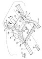
図1〜図11は本発明の一実施例を示すもので、図1は自動車の車体後部の斜視図、図2は図1の2方向矢視図、図3は図2の3−3線断面図、図4は図2の4部拡大図、図5は図4の5−5線断面図、図6は電源システムの分解斜視図、図7はバッテリボックスの分解斜視図、図8はバッテリ支持フレームの斜視図、図9は図2の9方向矢視図、図10はバッテリカバーの分解斜視図、図11はバッテリボックスの模式図である。 1 to 11 show an embodiment of the present invention. FIG. 1 is a perspective view of a rear part of a vehicle body, FIG. 2 is a view taken in the direction of the arrow in FIG. 1, and FIG. 4 is an enlarged view of part 4 of FIG. 2, FIG. 5 is a sectional view taken along line 5-5 of FIG. 4, FIG. 6 is an exploded perspective view of the power supply system, FIG. 7 is an exploded perspective view of the battery box, and FIG. 9 is a perspective view of the battery support frame, FIG. 9 is a view in the direction of arrow 9 in FIG. 2, FIG. 10 is an exploded perspective view of the battery cover, and FIG. 11 is a schematic view of the battery box.
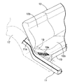
図1〜図4に示すように、走行用の動力源としてエンジンおよびモータ・ジェネレータを備えたハイブリッド自動車は、車体の左右両側部に車体前後方向に配置された一対のサイドフレーム11,11を備えており、リヤシート12のシートクッション12aの前部下面で左右のサイドフレーム11,11がクロスメンバ13により接続される。左右のサイドフレーム11,11、クロスメンバ13およびシートクッション12aの下面に囲まれた空間に燃料タンク14が配置されており、この燃料タンク14の左端から後上方に延びるフィラーチューブ15の上端に給油口16が設けられる。左右のサイドフレーム11,11はホイールハウス17,17に対応する位置に上方に湾曲する湾曲部11a,11aを備えており、その湾曲部11a,11aの頂点間に、モータ・ジェネレータの動力源となる電源システムのバッテリボックス18の左右両端部が接続され、そのバッテリボックス18はリヤシート12よりも後側で且つ燃料タンク14よりも上側に配置される。バッテリボックス18の右側面の前部から車体前方に向けて吸気ダクト19が接続され、またバッテリボックス18の右側面の後部から車体後方に向けて排気ダクト20が接続される。排気ダクト20の中間部にはファン21およびサイレンサ22が設けられる。
As shown in FIGS. 1 to 4, a hybrid vehicle including an engine and a motor / generator as a driving power source includes a pair of
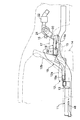
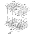
図5〜図9から明らかなように、複数のバッテリセルを直列に結合した36本の棒状のバッテリモジュール23…を複数のモジュールホルダ24…で一体に束ねたものが、一対の下部バッテリ支持フレーム25,25および一対の上部バッテリ支持フレーム26,26で上下から挟持される。中間部がバッテリモジュール23…の下面を支持すべく下向きに湾曲した一対の下部バッテリ支持フレーム25,25の両端は、固定ブラケット27,27で一体に結合される。バッテリモジュール23…の上面を支持すべく上向きに湾曲した一対の上部バッテリ支持フレーム26,26は、その左右両端部がボルト28…で下部バッテリ支持フレーム25,25の上面に固定される。
As apparent from FIGS. 5 to 9, a pair of lower battery support frames are obtained by integrally bundling 36 rod-
サイドフレーム11,11の湾曲部11a,11aの上面に、下部バッテリ支持フレーム25,25の両端の固定ブラケット27,27がボルト29…で結合される。サイドフレーム11,11の湾曲部11a,11aはホイールハウス17,17に対応する位置に設けられているため、図示せぬサスペンション装置のダンパーの上端が接続されて車輪からの大きな荷重が入力されるが、その部分をクロスメンバとして機能する強固な下部バッテリ支持フレーム25,25で接続することで、特別の補強部材を必要とせずに補強して車体の剛性を高めることができる。これにより、バッテリボックス18を搭載したことによる重量増加に対しても、従来の車体構造を大幅に変更することなく対応することが可能となる。
また重量の大きいバッテリボックス18をサイドフレーム11,11に支持することにより、その支持を強固なものとすることができる。しかも棒状のバッテリモジュール23…は車体前後方向に配置されており、これらのバッテリモジュール23…を車体左右方向に延びる下部バッテリ支持フレーム25,25および上部バッテリ支持フレーム26,26で支持することにより、その支持を容易かつ確実に行うことができる。
Further, by supporting the
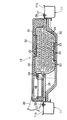
下部バッテリ支持フレーム25,25および上部バッテリ支持フレーム26,26で束ねられた複数本のバッテリモジュール23…は、発泡性の合成樹脂で形成された下部バッテリカバー30および上部バッテリカバー31によって覆われ、更にそれらの上面が下方が開放した金属製のバッテリケース32で覆われる。下部バッテリ支持フレーム25,25の左右両端部は、上部バッテリカバー31を貫通して外部に延出する。発泡性の合成樹脂よりなる下部バッテリカバー30および上部バッテリカバー31を金属製のバッテリケース32で覆うことにより、それらの下部バッテリカバー30、上部バッテリカバー31と内部のバッテリモジュール23…とを保護することができる。
The plurality of
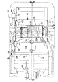
次に、図10および図11に基づいて、下部バッテリカバー30および上部バッテリカバー31の構造を説明する。尚、図11は図10に対応する模式図である。
Next, the structure of the
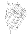
下部バッテリカバー30および上部バッテリカバー31は、車体左側に位置するバッテリ収納部Aと、車体右側に位置する冷却空気案内部Bとで構成される。バッテリ収納部Aは矩形状の上壁33Uおよび下壁33Lと、前後方向に延びる一対の第1側壁34L,34Rと、左右方向に延びる一対の第2側壁35f,35rとを備えて上下方向に偏平な直方体状に形成される。
The
バッテリ収納部Aにおいて、上壁33Uの下面に左右方向に形成された2本の仕切り壁33Ua,33Uaと、下壁33Lの上面に左右方向に形成された2本の仕切り壁33La,33Laとは、下部バッテリ支持フレーム25,25および上部バッテリ支持フレーム26,26に接しており、これらの仕切り壁33Ua,33Ua;33La,33Laにより後方に位置する2本の第1冷却通路36,36と、前方に位置する1本の第2冷却通路37とが区画される。また左側の第1側壁34Lに沿って前後方向に延びる連結通路38が形成される。第1冷却通路36,36の左端(終端)が連結通路38の後端(始端)に連通し、連結通路38の前端(終端)が第2冷却通路37の左端(始端)に連通することで、第1冷却通路36,36、連結通路38および第2冷却通路37は全体的にU字状に配置される。
In the battery storage part A, the two partition walls 33Ua and 33Ua formed in the left and right direction on the lower surface of the
上部バッテリカバー31の冷却空気案内部Bには、右側の第1側壁34Rの右側に連なる隔壁39が水平方向に形成され、その隔壁39と下部バッテリカバー30との間に冷却空気導入通路40が形成される。下部バッテリカバー30の右端前部には冷却空気導入通路40に連なる冷却空気導入口41が形成され、下部バッテリカバー30の右側の第1側壁34Rの後部に第1冷却通路36,36の始端に連なる第1連通口42が形成される。上部バッテリカバー31の右側の第1側壁34Rの前部に第2冷却通路37の終端に連なる第2連通口43が形成される
上部バッテリカバー31の隔壁39とバッテリケース32との間に冷却空気排出通路44が形成され、その冷却空気排出通路44の始端は第2連通口43に接続され、その終端には上部バッテリカバー31の隔壁39とバッテリケース32とによって冷却空気排出口45が形成される。上部バッテリカバー31の隔壁39の上面に、バッテリモジュール23…の高電圧を降圧するダウンバータ46が、冷却空気排出通路44内に位置するように配置される。
In the cooling air guide B of the
バッテリボックス18の冷却空気導入口41に接続された吸気ダクト19は、リヤシート12のシートバック12bの右側面からシートクッション12aの右側面に沿って配置され、シートクッション12aの右側面の前端に右前方を向いて開口する吸入口19aは、後部右ドアに隙間を存して対向する。従って、吸気ダクト19によってリヤシート12の着座性能が阻害されるのを防止しながら、特に夏期に車室内の適温に空調された空気をバッテリボックス18に供給することができる。しかも後部右ドアを閉じた状態で、吸気ダクト19の吸入口19aを見えにくくして外観を向上させることができる。また吸気ダクト19の通路断面積は、その何れの部位でも吸入口19aの断面積よりも大きく設定されており、これにより吸気ダクト19を流れる冷却空気の流通抵抗を最小限に抑えることができる(図6参照)。
The
リヤシート12の前方のフロアに、暖房用の空気を吹き出す吹出口48が設けられる。後方を向いて開口する吹出口48の延長線上に対して、吸気ダクト19の吸入口19aは上方かつ右方にずれており、これにより吹出口48から吹出た高温の空気が吸気ダクト19に直接吸入されないようにし、バッテリモジュール23…の冷却性能の低下を防止することができる。
On the floor in front of the
バッテリボックス18の冷却空気排出口45に連なる排気ダクト20は、それに設けたファン21およびサイレンサ22と共に、トランクルームの内装材49と車体外板50との間の空間に配置される(図2参照)。ファン21を内装材49で覆ったことで車室内に漏れる騒音を低減することができ、またサイレンサ22を設けたことで冷却空気の流れに伴う騒音を低減することができる。
The
次に、上記構成を備えた本発明の実施例の作用について説明する。 Next, the operation of the embodiment of the present invention having the above configuration will be described.
モータ・ジェネレータを駆動することで発熱したバッテリモジュール23…を冷却すべく排気ダクト20に設けたファン21を駆動すると、車室内の空気が吸気ダクト19の吸入口19aからバッテリボックス18に冷却空気導入口41に導入される。冷却空気導入口41に導入された冷却空気は、バッテリボックス18の冷却空気案内部Bの隔壁39の下方に設けた冷却空気導入通路40を前から後に流れた後に、バッテリボックス18のバッテリ収納部Aの右側の第1側壁34Rに設けた第1連通口42から2本の第1冷却通路36,36に流入する。
When the
後側の第2側壁35rに沿う第1冷却通路36,36を右から左に流れた冷却空気は、左側の第1側壁34Lに沿う連結通路38を後から前に流れ、更に前側の第2側壁35fに沿う第2冷却通路37を左から右に流れた後に、右側の第1側壁34Rに設けた第2連通口43から隔壁39の上方に設けた冷却空気排出通路44に排出される。
The cooling air that has flowed from the right to the left through the
冷却空気が第1冷却通路36,36および第2冷却通路37を流れる間に、そこに配置されたバッテリモジュール23…を冷却する。このとき、2本設けられた上流側の第1冷却通路36,36の冷却空気は比較的に低温であるが、流路断面積が大きいために冷却空気の流速が小さくなり、逆に1本だけ設けられた下流側の第2冷却通路37の冷却空気は比較的に高温であるが、流路断面積が小さいために冷却空気の流速が大きくなることで、全てのバッテリモジュール23…を均一に冷却することができる。
While the cooling air flows through the
またバッテリモジュール23…を冷却した後の冷却空気が通過する冷却空気排出通路44にダウンバータ46を配置したことで、バッテリモジュール23…を冷却した冷却空気を利用してダウンバータ46を冷却することができる。そして冷却空気排出口45から排気ダクト19に排出された冷却空気は、ファン21を通過してサイレンサ22で消音された後に、トランクルームの内装材49と車体外板50との間の空間に排出される。
Further, the
バッテリボックス18のバッテリ収納部Aの中心線L1は車体中心線L2に対して車体左側にずれており、その結果として車体右側に形成されたスペースに冷却空気案内部B、吸気ダクト19および排気ダクト20を配置したので、リヤシート12およびトランクルーム間の限られた空間にバッテリボックス18をコンパクトに配置することができる。しかも燃料タンク14のフィラーチューブ15を吸気ダクト19および排気ダクト20と反対側である車体左側に配置したので、フィラーチューブ15が吸気ダクト19および排気ダクト20と干渉するのを防止してレイアウトの自由度を高めることができる。
The center line L1 of the battery storage part A of the
またバッテリボックス18のバッテリ収納部Aに隣接して冷却空気案内部Bを一体に設け、この冷却空気案内部Bの内部で冷却空気導入通路40および冷却空気排出通路44を交差させたので、冷却空気案内部Bの右側面および後面にそれぞれ冷却空気導入口41および冷却空気排出口45を設けることが可能になり、吸気ダクト19および排気ダクト20のレイアウトの自由度が向上する。また隔壁39を挟んで冷却空気導入通路40および冷却空気排出通路44を上下に分離したので、冷却空気導入通路40および冷却空気排出通路44を無理なく交差させて冷却空気の流通抵抗の増加を最小限に抑えることができる。
Further, the cooling air guide B is integrally provided adjacent to the battery storage part A of the
尚、実施例では冷却空気案内部Bの右側面および後面にそれぞれ冷却空気導入口41および冷却空気排出口45を設けているが、吸気ダクト19および排気ダクト20のレイアウトの要請に応じて、それらを冷却空気案内部Bの任意の位置に設けることができ、これにより吸気ダクト19および排気ダクト20の干渉を回避してレイアウトの自由度を高めることができる。
In the embodiment, the cooling
以上、本発明の実施例を説明したが、本発明は上記実施例に限定されるものではなく、特許請求の範囲に記載された本発明を逸脱することなく種々の設計変更を行うことが可能である。 Although the embodiments of the present invention have been described above, the present invention is not limited to the above-described embodiments, and various design changes can be made without departing from the present invention described in the claims. It is .
11 サイドフレーム
11a 湾曲部
12 リヤシート
14 燃料タンク
17 ホイールハウス
18 バッテリボックス
23 バッテリモジュール
25 下部バッテリ支持フレーム(バッテリ支持フレーム)
30 下部バッテリカバー(バッテリカバー)
31 上部バッテリカバー(バッテリカバー)
32 バッテリケース
11 Side frame
11a curved portion
12 rear seats
14
30 Lower battery cover (battery cover)
31 Upper battery cover (battery cover)
32 battery case
Claims (3)
前記バッテリボックス(18)は前記バッテリモジュール(23)を支持して前記バッテリカバー(30,31)を車体左右方向に貫通するバッテリ支持フレーム(25)を備えており、
このバッテリ支持フレーム(25)の左右両端部を、前記ホイールハウス(17)に対応する位置で前記左右一対のサイドフレーム(11)の前記湾曲部(11a)にそれぞれ連結したことを特徴とするハイブリッド車両。 A pair of left and right side frames (11) extending in the longitudinal direction of the vehicle body are provided on both left and right sides of the vehicle body, and a fuel tank (14) is provided in a space surrounded by the side frames (11) and the lower surface of the rear seat (12). Each of the pair of left and right side frames (11) is provided with a curved portion (11a) that is curved at a position corresponding to a wheel house (17) that covers the upper part of the rear wheel of the vehicle body. The rear wheel suspension device is connected to (11a) so that the load of the suspension device can be input to the curved portion (11a), and a plurality of battery modules (23) are placed inside the battery cover (30, 31). accommodating the battery box (18), the rear seat is mounted to the vehicle body above the and the fuel tank rearward of (12) (14) , A hybrid vehicle that is for supplying power from the battery module to the motor to drive the vehicle (23),
The battery box (18) includes a battery support frame (25) that supports the battery module (23) and penetrates the battery cover (30, 31) in the lateral direction of the vehicle body.
The hybrid characterized in that the left and right end portions of the battery support frame (25 ) are respectively connected to the curved portions (11a) of the pair of left and right side frames (11) at positions corresponding to the wheel house (17). car both.
Priority Applications (1)
| Application Number | Priority Date | Filing Date | Title |
|---|---|---|---|
| JP2005163090A JP4732011B2 (en) | 2005-06-02 | 2005-06-02 | Hybrid vehicle |
Applications Claiming Priority (1)
| Application Number | Priority Date | Filing Date | Title |
|---|---|---|---|
| JP2005163090A JP4732011B2 (en) | 2005-06-02 | 2005-06-02 | Hybrid vehicle |
Publications (2)
| Publication Number | Publication Date |
|---|---|
| JP2006335243A JP2006335243A (en) | 2006-12-14 |
| JP4732011B2 true JP4732011B2 (en) | 2011-07-27 |
Family
ID=37556154
Family Applications (1)
| Application Number | Title | Priority Date | Filing Date |
|---|---|---|---|
| JP2005163090A Expired - Fee Related JP4732011B2 (en) | 2005-06-02 | 2005-06-02 | Hybrid vehicle |
Country Status (1)
| Country | Link |
|---|---|
| JP (1) | JP4732011B2 (en) |
Families Citing this family (21)
| Publication number | Priority date | Publication date | Assignee | Title |
|---|---|---|---|---|
| US9126477B2 (en) * | 2007-05-30 | 2015-09-08 | Ford Global Technologies, Llc | Ductless cooling system for a vehicle power storage unit |
| JP2010284984A (en) | 2009-06-09 | 2010-12-24 | Fuji Heavy Ind Ltd | Vehicle battery mounting structure |
| JP5163628B2 (en) * | 2009-11-10 | 2013-03-13 | 三菱自動車工業株式会社 | Electric vehicle battery mounting structure |
| JP5304711B2 (en) * | 2010-04-02 | 2013-10-02 | 三菱自動車工業株式会社 | Body reinforcement structure |
| JP5434860B2 (en) | 2010-09-17 | 2014-03-05 | トヨタ車体株式会社 | Battery pack mounting structure in vehicle |
| JP6115011B2 (en) * | 2012-02-20 | 2017-04-19 | スズキ株式会社 | Vehicle rear structure |
| JP5929609B2 (en) * | 2012-08-07 | 2016-06-08 | スズキ株式会社 | In-vehicle structure of battery pack |
| CN103660890B (en) * | 2012-09-03 | 2016-04-27 | 广州汽车集团股份有限公司 | A kind of electrokinetic cell pack assembly |
| JP6143172B2 (en) * | 2013-05-14 | 2017-06-07 | 本田技研工業株式会社 | Power storage device for vehicle |
| JP6037131B2 (en) * | 2013-07-29 | 2016-11-30 | 本田技研工業株式会社 | Power storage device for vehicle |
| JP5871983B2 (en) | 2014-03-28 | 2016-03-01 | 富士重工業株式会社 | Battery module protection structure mounted on the rear of the vehicle body |
| JP6510243B2 (en) * | 2015-01-16 | 2019-05-08 | 株式会社Subaru | Automotive battery |
| JP6118381B2 (en) * | 2015-09-30 | 2017-04-19 | 富士重工業株式会社 | Automotive battery |
| JP6512162B2 (en) | 2016-04-21 | 2019-05-15 | トヨタ自動車株式会社 | Vehicle battery mounting structure |
| DE102017100685A1 (en) * | 2017-01-16 | 2018-07-19 | Dr. Ing. H.C. F. Porsche Aktiengesellschaft | Energy supply system for a motor vehicle |
| CN107128367B (en) * | 2017-04-12 | 2019-01-29 | 广州电力机车有限公司 | 90 tons of new energy electric transmission dumper frames of one kind and its Vehicle Frame Design method |
| WO2019221223A1 (en) * | 2018-05-17 | 2019-11-21 | 本田技研工業株式会社 | Battery pack |
| WO2020162028A1 (en) * | 2019-02-08 | 2020-08-13 | 三菱自動車工業株式会社 | Battery pack mounting structure |
| JP6801737B2 (en) * | 2019-04-10 | 2020-12-16 | トヨタ自動車株式会社 | Vehicle battery mounted structure |
| JP7326944B2 (en) * | 2019-07-09 | 2023-08-16 | スズキ株式会社 | Vehicle battery protection structure |
| WO2025163765A1 (en) * | 2024-01-30 | 2025-08-07 | 三菱自動車工業株式会社 | Battery pack protection structure |
Family Cites Families (6)
| Publication number | Priority date | Publication date | Assignee | Title |
|---|---|---|---|---|
| JPS57139431A (en) * | 1981-06-10 | 1982-08-28 | Hitachi Zosen Corp | Feed bar driving device of rotary transfer press |
| JPH05193366A (en) * | 1992-01-22 | 1993-08-03 | Honda Motor Co Ltd | Fixing structure of battery for electric vehicle |
| JPH07186734A (en) * | 1993-12-27 | 1995-07-25 | Honda Motor Co Ltd | Electric vehicle battery box structure |
| JPH0867151A (en) * | 1994-08-30 | 1996-03-12 | Nissan Motor Co Ltd | Battery mounting structure for electric vehicles |
| JP4294372B2 (en) * | 2003-05-21 | 2009-07-08 | 本田技研工業株式会社 | In-vehicle structure of high-voltage components |
| JP4649849B2 (en) * | 2004-03-02 | 2011-03-16 | トヨタ自動車株式会社 | Storage mechanism mounting structure |
-
2005
- 2005-06-02 JP JP2005163090A patent/JP4732011B2/en not_active Expired - Fee Related
Also Published As
| Publication number | Publication date |
|---|---|
| JP2006335243A (en) | 2006-12-14 |
Similar Documents
| Publication | Publication Date | Title |
|---|---|---|
| JP4385020B2 (en) | Vehicle power supply | |
| JP4732011B2 (en) | Hybrid vehicle | |
| JP4602164B2 (en) | vehicle | |
| CN101340013B (en) | Vehicle power supply unit and battery cooling structure | |
| JP5210330B2 (en) | Vehicle power supply | |
| CN102582420B (en) | High-voltage apparatus having cooling structure and vehicle having the same | |
| CN102216100B (en) | Vehicle power source unit cooling structure | |
| JP4673692B2 (en) | Cooling structure for electrical equipment in vehicles | |
| JP4637504B2 (en) | Arrangement structure of high piezoelectric case | |
| CN102481837A (en) | Cooling Structure For High-voltage Electrical Component For Vehicle | |
| CN100579810C (en) | Vehicle power supply unit | |
| CN101535074A (en) | Electricity storage device and automobile | |
| JP4503345B2 (en) | Cooling structure for vehicle battery or high-voltage components | |
| JP5924130B2 (en) | Air conditioning structure for vehicle battery unit | |
| JP2016199105A (en) | Battery unit | |
| CN115179743A (en) | Cooling device for vehicle | |
| JP5253711B2 (en) | Battery cooling structure | |
| JP6546770B2 (en) | Battery cooling structure | |
| JPH07215070A (en) | Battery equipment for electric vehicles | |
| JP7676734B2 (en) | Battery pack | |
| JP2024129705A (en) | vehicle | |
| JP7604546B2 (en) | Battery pack | |
| JP2021075158A (en) | vehicle | |
| JP2010285151A (en) | Hybrid vehicle | |
| JP4845572B2 (en) | Vehicle power supply |
Legal Events
| Date | Code | Title | Description |
|---|---|---|---|
| A621 | Written request for application examination |
Free format text: JAPANESE INTERMEDIATE CODE: A621 Effective date: 20071129 |
|
| A977 | Report on retrieval |
Free format text: JAPANESE INTERMEDIATE CODE: A971007 Effective date: 20100728 |
|
| A131 | Notification of reasons for refusal |
Free format text: JAPANESE INTERMEDIATE CODE: A131 Effective date: 20100804 |
|
| A521 | Request for written amendment filed |
Free format text: JAPANESE INTERMEDIATE CODE: A523 Effective date: 20100930 |
|
| A01 | Written decision to grant a patent or to grant a registration (utility model) |
Free format text: JAPANESE INTERMEDIATE CODE: A01 Effective date: 20110406 |
|
| A01 | Written decision to grant a patent or to grant a registration (utility model) |
Free format text: JAPANESE INTERMEDIATE CODE: A01 |
|
| A61 | First payment of annual fees (during grant procedure) |
Free format text: JAPANESE INTERMEDIATE CODE: A61 Effective date: 20110420 |
|
| FPAY | Renewal fee payment (event date is renewal date of database) |
Free format text: PAYMENT UNTIL: 20140428 Year of fee payment: 3 |
|
| R150 | Certificate of patent or registration of utility model |
Free format text: JAPANESE INTERMEDIATE CODE: R150 |
|
| LAPS | Cancellation because of no payment of annual fees |