JP4731996B2 - Light emitting element and display device - Google Patents
Light emitting element and display device Download PDFInfo
- Publication number
- JP4731996B2 JP4731996B2 JP2005146844A JP2005146844A JP4731996B2 JP 4731996 B2 JP4731996 B2 JP 4731996B2 JP 2005146844 A JP2005146844 A JP 2005146844A JP 2005146844 A JP2005146844 A JP 2005146844A JP 4731996 B2 JP4731996 B2 JP 4731996B2
- Authority
- JP
- Japan
- Prior art keywords
- layer
- light
- responsible
- light emitting
- electrode
- Prior art date
- Legal status (The legal status is an assumption and is not a legal conclusion. Google has not performed a legal analysis and makes no representation as to the accuracy of the status listed.)
- Expired - Fee Related
Links
Images


Landscapes
- Electroluminescent Light Sources (AREA)
- Devices For Indicating Variable Information By Combining Individual Elements (AREA)
Description
本発明は、陽極、陰極、及び前記陽極と陰極との間に、エレクトロルミネセンス(以下、「EL」という。)と呼ばれる現象によって発光する薄膜を挟んだ構造からなる素子(以下、「発光素子」という。)、並びに該発光素子を基板上に備えた表示装置に関する。また、該発光素子を映像表示部に備えた電子機器に関する。 The present invention relates to an element (hereinafter referred to as “light emitting element”) having an anode, a cathode, and a structure in which a thin film emitting light by a phenomenon called electroluminescence (hereinafter referred to as “EL”) is sandwiched between the anode and the cathode. And a display device including the light-emitting element over a substrate. The present invention also relates to an electronic device provided with the light emitting element in a video display unit.
ELディスプレイは、次世代のフラットパネルディスプレイとして最も注目されている発光装置の一つである。発光装置に用いられる発光素子は、二つの電極間に有機化合物から成る薄膜(以下、「有機薄膜」という。)を設置し、電極に通電することによって発光を得るものである。陰極から注入された電子および陽極から注入された正孔が有機薄膜で再結合して分子励起子を形成し、その分子励起子が基底状態に戻る際に光子が放出される、すなわち発光に至る。この時、一つの電子と一つの正孔が再結合することによって分子励起子が一分子生成する。この分子励起子が発光を伴いながら基底状態に失活する際、励起状態と基底状態のエネルギー差に相当する波長の光子(以下、フォトンという。)が一つ放出される(これを輻射過程と呼ぶ。)。 An EL display is one of the light-emitting devices that has received most attention as a next-generation flat panel display. A light-emitting element used in a light-emitting device obtains light emission by placing a thin film made of an organic compound (hereinafter referred to as “organic thin film”) between two electrodes and energizing the electrodes. Electrons injected from the cathode and holes injected from the anode recombine in the organic thin film to form molecular excitons, and photons are emitted when the molecular excitons return to the ground state, that is, light emission occurs. . At this time, one molecule and one hole are recombined to generate one molecule exciton. When this molecular exciton is deactivated to the ground state with light emission, one photon (hereinafter referred to as photon) having a wavelength corresponding to the energy difference between the excited state and the ground state is emitted (this is called a radiation process). Call it.)
通常の有機EL素子では、有機薄膜は一対の陽極と陰極に挟まれている。従って、陽極と陰極から注入される正孔と電子(以下、正孔と電子を区別しない場合、キャリアと記す。)の数と放出されるフォトン数の比率、すなわち量子効率は1を超えることは無い。 In a normal organic EL element, the organic thin film is sandwiched between a pair of anode and cathode. Therefore, the ratio of the number of holes and electrons injected from the anode and the cathode (hereinafter referred to as “carrier” when the holes and electrons are not distinguished from each other) and the number of photons emitted, that is, the quantum efficiency exceeds 1. No.
このような制約を解決する方法の一つとして、前記陰極と陽極とは別に、素子内に新たに中間導電層を形成する手法が提案されている(特許文献1参照)。
特許文献1では、一対の陽極11と陰極12に挟まれた素子内に、Alq(8−ヒドロキシキノリンのAl錯体)とLiからなるAlq:Li層13とIn−Zn−O(インジウム・亜鉛酸化物)層14を形成し、これらの層の陽極側と陰極側の両方に有機層15、16が設置された有機EL素子が提案されている(図14参照)。なお、17は層間絶縁膜である。ここで、Alq:Li層とIn−Zn−O層を積層した層は中間導電層と定義されている。このような構成の有機EL素子では、通常の有機EL素子と同様、まず陽極と陰極からそれぞれ正孔と電子が注入される。正孔は陰極側へ、電子は陽極側へと輸送される。ここで特徴的なことは、前記中間導電層からもキャリアが供給されることである。すなわち、中間導電層の陽極側(Alq:Li層13側)から電子が有機層15に注入され、同時に中間導電層の陰極側(In−Zn−O層14側)から正孔が有機層16に注入される。陽極側の有機層15では、陽極11から注入された正孔と中間導電層13、14から注入された電子が再結合し、分子励起子が生成して発光を得ることができる。同様に陰極側の有機層16においては、陰極12から注入された電子と前記中間導電層13、14から注入された正孔が再結合し、生成する分子励起子の輻射過程によって発光が得られる。
In
上述した機構により、あたかもこの有機EL素子は、通常の有機EL素子を直列に並べたものとほぼ同様の効果を得ることができる。すなわち、通常の有機EL素子と比較して駆動電圧はほぼ2倍になるものの、同じ電流密度から2倍のフォトン数を得ることができるのである。従って、量子効率はほぼ2倍となるのである。この手法を応用することで、さらに量子効率を増大させることも可能である。例えば二つの中間導電層と三つの有機薄膜を交互に設置すれば、3つの有機EL素子を直列に設置したのとほぼ同じ効果が得られる。従って、駆動電圧は約3倍になるが、同時に量子効率はほぼ3倍になり、高輝度の有機EL素子を提供することが可能となる。 Due to the mechanism described above, this organic EL element can obtain almost the same effect as that obtained by arranging ordinary organic EL elements in series. That is, although the driving voltage is almost doubled as compared with a normal organic EL element, it is possible to obtain twice the number of photons from the same current density. Therefore, the quantum efficiency is almost doubled. By applying this method, the quantum efficiency can be further increased. For example, if two intermediate conductive layers and three organic thin films are alternately arranged, the same effect as that obtained by arranging three organic EL elements in series can be obtained. Therefore, the driving voltage is about 3 times, but at the same time, the quantum efficiency is almost 3 times, and it is possible to provide a high-luminance organic EL element.
この概念を実現するための必要条件は、有機層に挟まれる中間導電層が透明であると言うことである。この必要条件をクリアするため、中間導電層に使用できる材料に制約が生まれる。これまでに様々な材料が提案されているが、現実的に使用されているものとしては、1)Alqやバソクプロイン(BCP)などの電子輸送性化合物と、アルカリ金属などの電子注入性化合物からなる混合層とITO(インジウムスズ酸化物)やIZO(インジウム亜鉛酸化物)などの透明電極の積層、2)前記電子輸送性化合物と電子注入性化合物からなる混合層と金属酸化物の積層、3)前記電子輸送性化合物と電子注入性化合物からなる混合層と電子受容性有機化合物の積層、などに限られている。 A necessary condition for realizing this concept is that the intermediate conductive layer sandwiched between the organic layers is transparent. In order to satisfy this requirement, there are restrictions on the materials that can be used for the intermediate conductive layer. Various materials have been proposed so far, but those that are actually used include 1) an electron transporting compound such as Alq and bathocuproine (BCP) and an electron injecting compound such as an alkali metal. Lamination of mixed layer and transparent electrode such as ITO (Indium Tin Oxide) or IZO (Indium Zinc Oxide), 2) Lamination of mixed layer consisting of electron transporting compound and electron injecting compound and metal oxide, 3) It is limited to a mixed layer composed of the electron transporting compound and the electron injecting compound, and a stacked layer of an electron accepting organic compound.
上述した材料を用いることで、中間導電層は透明性を維持することができるが、やはり材料の制約は非常に大きく、素子の作製プロセスも複雑になる。例えば特許文献1の手法で説明すると、まず有機層は通常、真空蒸着法によって形成される。この手法によって電子輸送性化合物と電子注入性化合物の混合層を有機層上に容易に形成することができる。しかし、ITOやIZOなどの透明電極は真空蒸着法では成膜することができず、スパッタにより成膜される。従って、素子を一度蒸着用の成膜室からスパッタ用の成膜室へ移動した後に、これらの透明電極を形成しなければならず、製造プロセスが煩雑となる。
By using the above-described materials, the intermediate conductive layer can maintain transparency, but the material restrictions are still very large, and the device manufacturing process becomes complicated. For example, if it demonstrates with the method of
また、特許文献1に関連する技術として、特許文献2及び3に示される、複数個の発光ユニットが1層の等電位面を形成する層によって仕切られている有機エレクトロルミネッセンス素子、並びに、特許文献4に示される、二つの有機EL層の間に、導電体薄膜層が挿入された構造を有する有機EL素子が知られている。
本発明は、上記問題点に鑑みてなされたものであり、発光層として機能する有機薄膜に挟まれた中間導電層として使用可能な材料の選択幅を大幅に広げ、発光効率が高く、消費電力が小さく、信頼性の高い有機EL素子に代表される発光素子及び該発光素子を用いた表示装置(発光装置)を提供することを課題とする。 The present invention has been made in view of the above-described problems, and greatly expands the selection range of materials that can be used as an intermediate conductive layer sandwiched between organic thin films functioning as a light emitting layer, and has high luminous efficiency and power consumption. It is an object to provide a light-emitting element typified by an organic EL element with a small size and high reliability, and a display device (light-emitting device) using the light-emitting element.
本発明に係る発光素子は、第1の電極と、第1の発光層と、中間導電層と、第2の発光層と、第2の電極と、を少なくとも積層してなる発光素子であり、前記中間導電層は電子注入を担う層と、前記電子注入を担う層と接する正孔注入を担う層を含み、前記電子注入を担う層と前記正孔注入を担う層の少なくとも一方は島状の層であることを特徴とする。ここで、第1の電極は、陽極の機能を有するものであってもよいし、陰極の機能を有するものであっても良い。一方、第2の電極は、第1の電極と反対の極性を有するものであれば、陽極でも陰極でも良い。また、電子注入を担う島状の層、正孔注入を担う層は、合わせて中間導電層とも呼ばれ、該層は第1の電極及び第2の電極の極性に応じて、適宜その積層順を選択することができる。また、電子注入を担う層を島状にする代わりに、正孔注入を担う層を島状としても良い。また、両者とも島状にしても良い。なお、ここでいう島状の層とは、島状に点在して層が形成されてなり、ドット状、突起状、またはそれらが集まった塊(クラスター状)などであってもよく、その形状は問わない。また、島状に点在する配置の状態についても、ランダム又は意図的であっても構わない。いずれにせよ、中間導電層のうち電子注入を担う層が、陽極側の発光層に接しており、正孔注入を担う層が、陰極側の発光層に接しており、かつ、電子注入及び正孔注入を担う層が接している構成とすればよい。 The light-emitting element according to the present invention is a light-emitting element formed by laminating at least a first electrode, a first light-emitting layer, an intermediate conductive layer, a second light-emitting layer, and a second electrode, The intermediate conductive layer includes a layer responsible for electron injection and a layer responsible for hole injection in contact with the layer responsible for electron injection, and at least one of the layer responsible for electron injection and the layer responsible for hole injection is island-shaped. It is a layer. Here, the first electrode may have an anode function, or may have a cathode function. On the other hand, the second electrode may be an anode or a cathode as long as it has a polarity opposite to that of the first electrode. In addition, the island-shaped layer responsible for electron injection and the layer responsible for hole injection are collectively referred to as an intermediate conductive layer, and the layers are appropriately stacked according to the polarity of the first electrode and the second electrode. Can be selected. Further, instead of making the layer responsible for electron injection into an island shape, the layer responsible for hole injection may be shaped like an island. Moreover, both may be island-shaped. In addition, the island-like layer referred to here is a layer formed by being scattered in an island shape, and may be a dot shape, a protrusion shape, or a lump (cluster shape) in which they are collected. The shape does not matter. Further, the arrangement of the islands may be random or intentional. In any case, the layer in charge of electron injection in the intermediate conductive layer is in contact with the light emitting layer on the anode side, the layer in charge of hole injection is in contact with the light emitting layer on the cathode side, and A layer in charge of hole injection may be in contact.
また、上記発明に係る発光素子において、第2の発光層上に、新たに設けられる中間導電層(電子注入を担う層及び正孔注入を担う層)を介して第3の発光層を形成しても良い。この場合において、少なくとも一の中間導電層に含まれる、電子注入を担う層又は正孔注入を担う層の少なくとも一方は、島状であることが望ましい。すなわち、発光層を3層構造とした場合、中間導電層が2層挟持されるわけであるが、その少なくとも一方における電子注入を担う層又は正孔注入を担う層の少なくとも一方を島状とすればよい。また、発光層並びに中間導電層の積層数に、特に制限はない。例えば、発光層を4層積層した場合、それら発光層の間に3層の中間導電層
を挟持させる。また或いは、発光層を5層とした場合には、それら発光層の間に4層の中間導電層を挟持させる。
In the light-emitting element according to the above invention, a third light-emitting layer is formed over the second light-emitting layer through a newly provided intermediate conductive layer (a layer responsible for electron injection and a layer responsible for hole injection). May be. In this case, it is desirable that at least one of the layer responsible for electron injection or the layer responsible for hole injection included in at least one intermediate conductive layer has an island shape. That is, when the light emitting layer has a three-layer structure, two intermediate conductive layers are sandwiched, but at least one of the layer responsible for electron injection or the hole responsible for hole injection in at least one of them is formed into an island shape. That's fine. Moreover, there is no restriction | limiting in particular in the lamination | stacking number of a light emitting layer and an intermediate | middle conductive layer. For example, when four light emitting layers are stacked, three intermediate conductive layers are sandwiched between the light emitting layers. Alternatively, when five light emitting layers are used, four intermediate conductive layers are sandwiched between the light emitting layers.
具体的には、第1の電極と、複数の発光層と、前記複数の発光層の間に挟まれた複数の中間導電層と、第2の電極とを積層してなる発光素子であり、前記中間導電層は電子注入を担う層と、前記電子注入を担う層と接する正孔注入層を担う層を含み、前記電子注入を担う層と前記正孔注入層を担う層の少なくとも一方は島状の層であることを特徴とする。 Specifically, a light-emitting element formed by laminating a first electrode, a plurality of light-emitting layers, a plurality of intermediate conductive layers sandwiched between the plurality of light-emitting layers, and a second electrode, The intermediate conductive layer includes a layer responsible for electron injection and a layer responsible for a hole injection layer in contact with the layer responsible for electron injection, and at least one of the layer responsible for electron injection and the layer responsible for the hole injection layer is an island. It is characterized by being a layer of shape.
さらに具体的には、二つの電極の間に、1番目からn番目(nは2以上の整数)までのn個の発光層を順次積層してなり、k番目(kは、1≦k≦(n−1)なる整数)の発光層とk+1番目の発光層との間には、中間導電層が含まれる。さらに、前記中間導電層には電子注入を担う層と、前記電子注入を担う層と接する正孔注入を担う層を含み、前記電子注入を担う層と前記正孔注入を担う層の少なくとも一方は島状の層であることを特徴とする。さらに、第1の電極とは画素電極であり、第2の電極とは対向電極である。 More specifically, first to nth (n is an integer of 2 or more) n light emitting layers are sequentially stacked between two electrodes, and kth (k is 1 ≦ k ≦). An intermediate conductive layer is included between the (n-1) integer light emitting layer and the (k + 1) th light emitting layer. Further, the intermediate conductive layer includes a layer responsible for electron injection and a layer responsible for hole injection in contact with the layer responsible for electron injection, and at least one of the layer responsible for electron injection and the layer responsible for hole injection is It is an island-like layer. Further, the first electrode is a pixel electrode, and the second electrode is a counter electrode.
また、本発明に係る表示装置は、基板上に設けられたトランジスタと、層間絶縁膜を介して前記トランジスタと接続された発光素子とを有し、前記発光素子は、第1の電極と、第1の発光層と、中間導電層と、第2の発光層と、第2の電極と、を少なくとも積層してなる発光素子であり、前記中間導電層は電子注入を担う層と、前記電子注入を担う層と接する正孔注入を担う層を含み、前記電子注入を担う層と前記正孔注入を担う層の少なくとも一方は島状の層であることを特徴とする。ここで、発光素子における第1の電極は、陽極の機能を有するものであってもよいし、陰極の機能を有するものであっても良い。一方、第2の電極は、第1の電極と反対の極性を有するものであれば、陽極でも陰極でも良い。また、電子注入を担う島状の層、正孔注入を担う層は、合わせて中間導電層とも呼ばれ、該層は第1の電極及び第2の電極の極性に応じて、適宜その積層順を選択することができる。また、電子注入を担う層を島状にする代わりに、正孔注入を担う層を島状としても良い。また、両者とも島状にしても良い。いずれにせよ、中間導電層のうち電子注入を担う層が、陽極側の発光層に接しており、正孔注入を担う層が、陰極側の発光層に接しており、かつ、電子注入及び正孔注入を担う層が接している構成とすればよい。 The display device according to the present invention includes a transistor provided over a substrate, and a light-emitting element connected to the transistor through an interlayer insulating film, the light-emitting element including a first electrode, a first electrode, 1 is a light-emitting element formed by laminating at least a light-emitting layer, an intermediate conductive layer, a second light-emitting layer, and a second electrode, wherein the intermediate conductive layer is a layer responsible for electron injection, and the electron injection And a layer responsible for hole injection in contact with the layer responsible for electron transport, and at least one of the layer responsible for electron injection and the layer responsible for hole injection is an island-like layer. Here, the first electrode in the light-emitting element may have an anode function or a cathode function. On the other hand, the second electrode may be an anode or a cathode as long as it has a polarity opposite to that of the first electrode. In addition, the island-shaped layer responsible for electron injection and the layer responsible for hole injection are collectively referred to as an intermediate conductive layer, and the layers are appropriately stacked according to the polarity of the first electrode and the second electrode. Can be selected. Further, instead of making the layer responsible for electron injection into an island shape, the layer responsible for hole injection may be shaped like an island. Moreover, both may be island-shaped. In any case, the layer in charge of electron injection in the intermediate conductive layer is in contact with the light emitting layer on the anode side, the layer in charge of hole injection is in contact with the light emitting layer on the cathode side, and A layer in charge of hole injection may be in contact.
また、上記発明に係る表示装置において、第2の発光層上に、新たに設けられる中間導電層(電子注入を担う層及び正孔注入を担う層)を介して第3の発光層を形成しても良い。この場合において、少なくとも一の中間導電層に含まれる、電子注入を担う層又は正孔注入を担う層の少なくとも一方は、島状であることが望ましい。すなわち、発光層を3層構造とした場合、中間導電層が2層挟持されるわけであるが、その少なくとも一方における電子注入を担う層又は正孔注入を担う層の少なくとも一方を島状とすればよい。また、発光層並びに中間導電層の積層数に、特に制限はない。例えば、発光層を4層積層した場合、それら発光層の間に3層の中間導電層を挟持させる。また或いは、発光層を5層とした場合には、それら発光層の間に4層の中間導電層を挟持させる。 In the display device according to the invention, a third light-emitting layer is formed on the second light-emitting layer via a newly provided intermediate conductive layer (a layer responsible for electron injection and a layer responsible for hole injection). May be. In this case, it is desirable that at least one of the layer responsible for electron injection or the layer responsible for hole injection included in at least one intermediate conductive layer has an island shape. That is, when the light emitting layer has a three-layer structure, two intermediate conductive layers are sandwiched, but at least one of the layer responsible for electron injection or the hole responsible for hole injection in at least one of them is formed into an island shape. That's fine. Moreover, there is no restriction | limiting in particular in the lamination | stacking number of a light emitting layer and an intermediate | middle conductive layer. For example, when four light emitting layers are stacked, three intermediate conductive layers are sandwiched between the light emitting layers. Alternatively, when five light emitting layers are used, four intermediate conductive layers are sandwiched between the light emitting layers.
具体的には基板上に設けられたトランジスタと、層間絶縁膜を介して前記トランジスタと接続された発光素子とを有し、前記発光素子は、第1の電極と、複数の発光層と、前記複数の発光層の間に挟まれた複数の中間導電層と、第2の電極とを積層してなる発光素子であり、前記中間導電層は電子注入を担う層と、前記電子注入を担う層と接する正孔注入層を担う層を含み、前記電子注入を担う層と前記正孔注入層を担う層の少なくとも一方は島状の層であることを特徴とする。 Specifically, a transistor provided over a substrate, and a light-emitting element connected to the transistor through an interlayer insulating film, the light-emitting element includes a first electrode, a plurality of light-emitting layers, A light-emitting element formed by laminating a plurality of intermediate conductive layers sandwiched between a plurality of light-emitting layers and a second electrode, wherein the intermediate conductive layer is a layer responsible for electron injection and a layer responsible for electron injection And a layer responsible for the hole injection layer in contact with the substrate, and at least one of the layer responsible for the electron injection and the layer responsible for the hole injection layer is an island-like layer.
さらに具体的には、基板上に設けられたトランジスタと、層間絶縁膜を介して前記トランジスタと接続された発光素子とを有し、前記発光素子は、二つの電極の間に、1番目からn番目(nは2以上の整数)までのn個の発光層を順次積層してなり、k番目(kは、1≦k≦(n−1)なる整数)の発光層とk+1番目の発光層との間には、中間導電層が含まれ、前記中間導電層には電子注入を担う層と、前記電子注入を担う層と接する正孔注入を担う層を含み、前記電子注入を担う層と前記正孔注入を担う層の少なくとも一方は島状の層であることを特徴とする。さらに、第1の電極とは画素電極であり、第2の電極とは対向電極である。 More specifically, the transistor includes a transistor provided on a substrate and a light emitting element connected to the transistor through an interlayer insulating film, and the light emitting element includes n-th electrode between two electrodes. N light emitting layers up to the number (n is an integer of 2 or more) are sequentially stacked, and the kth light emitting layer (k is an integer satisfying 1 ≦ k ≦ (n−1)) and the k + 1th light emitting layer. An intermediate conductive layer is included, and the intermediate conductive layer includes a layer responsible for electron injection, a layer responsible for hole injection in contact with the layer responsible for electron injection, and a layer responsible for electron injection. At least one of the layers responsible for hole injection is an island-like layer. Further, the first electrode is a pixel electrode, and the second electrode is a counter electrode.
本発明に係る発光素子は、第1の電極と第2の電極の間に複数の発光層を有するEL素子において、各発光層の間に中間導電層を設け、かつ中間導電層(複数の中間導電層が設けられる場合においては、それらの少なくとも一の中間導電層)において、正孔注入又は電子注入を担う層のいずれかが、膜状ではなく、島状に形成されていることを特徴とする。このような構造を採用することによって、以下のような効果を得ることができる。 The light-emitting element according to the present invention is an EL element having a plurality of light-emitting layers between a first electrode and a second electrode. An intermediate conductive layer is provided between each light-emitting layer, and an intermediate conductive layer (a plurality of intermediate layers) is provided. In the case where a conductive layer is provided, in any of those at least one intermediate conductive layer), one of the layers responsible for hole injection or electron injection is formed in an island shape instead of a film shape. To do. By adopting such a structure, the following effects can be obtained.
まず、中間導電層の電子(又は正孔)を注入する層に関し、材料の透明性を一切考慮する必要が無いことである。たとえ可視部に大きな吸光係数を有する中間導電層であっても、島状に形成すれば吸収自体は無視できるほどに小さくなる。従って、発光層からの発光は、中間導電層によって殆んど吸収されることが無い。 First, regarding the layer for injecting electrons (or holes) of the intermediate conductive layer, it is not necessary to consider the transparency of the material at all. Even if the intermediate conductive layer has a large extinction coefficient in the visible region, the absorption itself is negligibly small if it is formed in an island shape. Therefore, light emitted from the light emitting layer is hardly absorbed by the intermediate conductive layer.
また、中間導電層として有機材料(特に芳香族化合物)を用いた場合には、積極的な分子設計をしない限り、中間導電層の結晶性は高くなってしまう。その結果素子の特性が大幅に変化し、最悪の場合には両電極間で導通してショートに至る。しかし、本発明に係る構成を採用した場合には、個々の島状の層が結晶化しても結晶化が発光素子の特性に及ぼす影響は小さくなる又は無視することができるため、結晶化による発光素子の特性変化を抑制することができる。 Further, when an organic material (especially an aromatic compound) is used as the intermediate conductive layer, the crystallinity of the intermediate conductive layer becomes high unless an aggressive molecular design is performed. As a result, the characteristics of the element change drastically, and in the worst case, conduction occurs between both electrodes, resulting in a short circuit. However, when the configuration according to the present invention is adopted, the influence of crystallization on the characteristics of the light-emitting element can be reduced or ignored even if each island-shaped layer is crystallized. Changes in the characteristics of the element can be suppressed.
さらに、当然のことながら材料自身も少量使用すればよく、その結果、素子の作製時間も短縮することができ、コスト低減にも繋がる。このように、従来は膜状に形成されていた中間導電層の一部を島状に形成することで、様々な効果を生み出すことができる。 Furthermore, as a matter of course, the material itself may be used in a small amount, and as a result, the time for manufacturing the element can be shortened, leading to cost reduction. Thus, various effects can be produced by forming a part of the intermediate conductive layer, which has been conventionally formed in a film shape, in an island shape.
また、本発明に係る表示装置は、上記作用効果を有する発光素子を備えていることにより、光取り出し効率が高く、消費電力が小さく、低コスト、高寿命といった様々な作用効果をもたらす。 In addition, since the display device according to the present invention includes the light-emitting element having the above-described effects, various effects such as high light extraction efficiency, low power consumption, low cost, and long life are brought about.
本発明の実施の形態について、図面を用いて詳細に説明する。但し、本発明は以下の説明に限定されず、本発明の趣旨及びその範囲から逸脱することなくその形態及び詳細を様々に変更することができる。従って、本発明は以下に示す実施の形態の記載内容に限定して解釈されるものではない。例えば、以下に述べる実施の形態及び各実施例の特徴的部分を組み合わせて実施することが可能である。なお、以下に説明する本発明の構成において、同じものを指す符号は異なる図面間で共通して用いる。 Embodiments of the present invention will be described in detail with reference to the drawings. However, the present invention is not limited to the following description, and various changes and modifications can be made without departing from the spirit and scope of the present invention. Therefore, the present invention should not be construed as being limited to the description of the embodiments below. For example, it is possible to combine the embodiments described below and the characteristic portions of each example. Note that in the structures of the present invention described below, the same reference numerals are used in common in different drawings.
本発明の実施の形態を図1を用いて説明する。なお、図1では、二層の発光層を一つの中間導電層で隔たれた素子構造が示されているが、発光層の層数に制約は無い。また、該構造により、中間導電層の数は、発光層の総数より1つ少ないものとなる。 An embodiment of the present invention will be described with reference to FIG. Note that FIG. 1 shows an element structure in which two light emitting layers are separated by one intermediate conductive layer, but the number of light emitting layers is not limited. Further, due to the structure, the number of intermediate conductive layers is one less than the total number of light emitting layers.
まず、有機EL素子では、発光を取り出す必要があるため、少なくとも陽極、または陰極の一方が透明である必要がある。以下、基板上のうち、基板側に透明な陽極を形成し、陽極側から発光を取り出すことのできる発光素子、所謂ボトムエミッション型(下面出射型)発光素子について説明する。 First, since it is necessary to extract emitted light in an organic EL element, at least one of the anode and the cathode needs to be transparent. Hereinafter, a so-called bottom emission type (bottom emission type) light emitting element, in which a transparent anode is formed on the substrate side and light emission can be extracted from the anode side, will be described.
まず、発光素子等を担持するための基板101を用意する。基板101としては、石英やガラスのみならず、紙やプラスチック樹脂なども用いることができる。また、薄膜トランジスタ(以下、TFTと記す。)があらかじめ搭載された基板を用いることも可能である。本発明の形態では基板上に透明な陽極102を形成し、基板側に光を取り出すので、基板に可視光透過性があればよい。透明な陽極としては、ITOやIZOなどの、導電性金属酸化物が好適である。これらの導電性金属酸化物膜は、通常スパッタにより成膜されるが、ゾル−ゲル法などを応用して作製しても構わない。また、金属酸化物以外の材料として、金などの仕事関数の大きな金属を用いることも可能である。ただしこの場合には、光透過性を考慮して、超薄膜を形成する。
First, a
こうして形成された陽極上に第1の発光層103が形成される。この発光層は、主として有機化合物を用いて形成するが、単一組成の薄膜を用いて形成してもよい。例えばトリス(8−キノリノラト)アルミニウム(略称:Alq3)、トリス(4−メチル−8−キノリノラト)アルミニウム(略称:Almq3)、ビス(10−ヒドロキシベンゾ[h]−キノリナト)ベリリウム(略称:BeBq2)、ビス(2−メチル−8−キノリノラト)−(4−フェニルフェノラト)−アルミニウム(略称:BAlq)、ビス[2−(2−ヒドロキシフェニル)−ベンゾオキサゾラト]亜鉛(略称:Zn(BOX)2)、ビス[2−(2−ヒドロキシフェニル)−ベンゾチアゾラト]亜鉛(略称:Zn(BTZ)2)などの典型金属錯体が挙げられる。あるいは9,10−ジフェニルアントラセンや4,4’−ビス(2,2−ジフェニルエテニル)ビフェニルなどの炭化水素を含む化合物なども好適である。
A first
また、発光層は複数の材料の混合層であってもよい。上述した発光体に、蛍光材料、あるいは燐光材料を少量混合することで、発光効率を上げることができる。蛍光材料としてはクマリン誘導体、キナクリドン誘導体、アクリドン誘導体、ピレン誘導体、ペリレン誘導体、アントラセン誘導体、ピロン誘導体などが挙げられる。燐光材料としては、三重項発光材料としては、トリス(2−フェニルピリジン)イリジウム(以下、「Ir(ppy)3」と記す)、2,3,7,8,12,13,17,18−オクタエチル−21H,23H−ポルフィリン−白金(以下、「PtOEP」と記す)など、Ir、Ru、Rh、Pt、あるいは希土類金属などの遷移金属錯体が挙げられる。 The light emitting layer may be a mixed layer of a plurality of materials. Luminous efficiency can be increased by mixing a small amount of a fluorescent material or a phosphorescent material with the above-described light emitter. Examples of the fluorescent material include coumarin derivatives, quinacridone derivatives, acridone derivatives, pyrene derivatives, perylene derivatives, anthracene derivatives, and pyrone derivatives. As the phosphorescent material, as the triplet light emitting material, tris (2-phenylpyridine) iridium (hereinafter referred to as “Ir (ppy) 3 ”), 2, 3, 7, 8, 12, 13, 17, 18- Examples include transition metal complexes such as octaethyl-21H, 23H-porphyrin-platinum (hereinafter referred to as “PtOEP”) such as Ir, Ru, Rh, Pt, or rare earth metals.
一方、発光層は積層構造の膜であってもよい。積層構造とすることにより、上述した単一組成の発光層、あるいは混合発光層を用いた場合と比較して、電子と正孔の注入バランスを制御することが容易となり、より発光効率の改善を図ることができる。例えば、上述した単一組成、あるいは混合組成の発光層以外に、注入された正孔を効率よく発光層へ輸送する正孔輸送層、注入された電子を効率よく発光層へ輸送する電子輸送層を設けるのが良い。そして、本明細書では発光層に加え、これらの正孔輸送層、電子輸送層、或いは正孔注入層、電子注入層を付加したものも発光層と呼ぶことがある。正孔輸送層に相応しい材料としては、芳香族アミン(すなわち、ベンゼン環−窒素の結合を有するもの)を含む化合物である。広く用いられている材料として、4,4’−ビス[N−(3−メチルフェニル)−N−フェニル−アミノ]−ビフェニル,その誘導体である4,4’−ビス[N−(1−ナフチル)−N−フェニル−アミノ]−ビフェニル、4,4’,4’’−トリス(N,N−ジフェニル−アミノ)−トリフェニルアミン、4,4’,4’’−トリス[N−(3−メチルフェニル)−N−フェニル−アミノ]−トリフェニルアミンなどのスターバースト型芳香族アミン化合物が挙げられる。電子輸送層に好適な材料としては、上記典型金属錯体が挙げられるが、他に3−(4−tert−ブチルフェニル)−4−(4−エチルフェニル)−5−(4−ビフェニリル)−1,2,4−トリアゾールなどのトリアゾール誘導体、バソフェナントロリンやバソキュプロインなどのフェナントロリン誘導体、あるいは、ビス(5−メチルベンゾオキサゾール−2−イル)スチルベンなどのベンゾオキサゾール誘導体を用いても良い。 On the other hand, the light emitting layer may be a film having a laminated structure. By adopting a laminated structure, it becomes easier to control the injection balance of electrons and holes, compared with the case where the light emitting layer having a single composition or the mixed light emitting layer described above is used, and the luminous efficiency is further improved. Can be planned. For example, in addition to the light emitting layer having the single composition or the mixed composition described above, a hole transport layer that efficiently transports injected holes to the light emitting layer, and an electron transport layer that efficiently transports injected electrons to the light emitting layer. It is good to provide. In this specification, in addition to the light-emitting layer, the hole transport layer, the electron transport layer, or the hole injection layer or the electron injection layer added may be referred to as a light-emitting layer. A material suitable for the hole transport layer is a compound containing an aromatic amine (that is, a compound having a benzene ring-nitrogen bond). As a widely used material, 4,4′-bis [N- (3-methylphenyl) -N-phenyl-amino] -biphenyl and its derivative 4,4′-bis [N- (1-naphthyl) ) -N-phenyl-amino] -biphenyl, 4,4 ′, 4 ″ -tris (N, N-diphenyl-amino) -triphenylamine, 4,4 ′, 4 ″ -tris [N- (3 And starburst aromatic amine compounds such as -methylphenyl) -N-phenyl-amino] -triphenylamine. Examples of the material suitable for the electron transport layer include the above-mentioned typical metal complexes. In addition, 3- (4-tert-butylphenyl) -4- (4-ethylphenyl) -5- (4-biphenylyl) -1 Triazole derivatives such as 2,2,4-triazole, phenanthroline derivatives such as bathophenanthroline and bathocuproin, or benzoxazole derivatives such as bis (5-methylbenzoxazol-2-yl) stilbene may be used.
成膜方法は真空蒸着法だけではなく、スピンコーティング法、ディップコーティング法、スプレー法などの、所謂湿式法を採用しても構わない。 The film forming method is not limited to the vacuum deposition method, and a so-called wet method such as a spin coating method, a dip coating method, or a spray method may be employed.
次に中間導電層を形成するが、本実施の形態では陽極側から発光素子を形成していることから、まず始めに電子注入を担う層104を形成する。ここで、電子注入を担う層104は、図示するように島状に形成すればよい。島状に形成するためには、例えば蒸着法によって形成することが好ましい。この場合において具体的には、まず昇華した材料が核を形成した後、その核が成長し、異なる核から成長したクラスタが互いに結合する前に、蒸着プロセスを停止すればよい。また、電子注入を担う層104を形成するのに適した材料としては、まず、仕事関数の小さい金属、およびその金属化合物が挙げられる。例えばMg−Ag合金、Al−Li合金、Mg−Li合金、Ca3N2、Mg3N2などである。また金属の他、有機半導体にドナーをドープしたものが挙げられる。ここで言う有機半導体の好ましい例としては、アクセプター性を有する化合物であり、発光素子においてよく用いられる電子輸送性材料を用いればよい。例えばAlqなどに代表される典型金属錯体、フェナントロリン誘導体、トリアジン誘導体、オキサゾール誘導体、キノリン誘導体、キノキサリン誘導体などが挙げられる。また、テトラシアノキノジメタンやテトラシアノエチレン、テトラクロロキノンなどの電子受容性化合物も好例である。他の例としては、ルブレンやペリレン誘導体などの縮合芳香族炭化水素が挙げられる。また、グラファイトなどの導電性材料も用いることができる。さらに、ポリフェニレンビニレンやポリフェニレンエチニレン、ポリピリジンなどの共役高分子も用いることができる。ただしこの場合には、発光層にも高分子を用いることが好ましい。さらに、中間導電層を形成するために用いる高分子を溶解する溶媒に、発光層を形成するために用いる高分子が溶解しないように設計することが好ましい。これは、高分子材料は通常、湿式法によって成膜されるため、高分子材料を溶解する溶媒によって発光層が溶解してしまい、薄膜構造が破壊されるのを阻止するためである。有機半導体にドープするドナーとしては、アルカリ金属、アルカリ土類金属などの仕事関数の小さい金属が良い。あるいはテトラチアフルバレンなどの電子過剰型有機化合物でも良い。ただし、有機半導体のアクセプター性は強いことが必須である。これは、電子過剰型有機化合物のドナー性はアルカリ金属やアルカリ土類金属のそれよりも小さいためである。有機半導体以外の例としては、アルカリ金属、アルカリ土類金属、希土類金属、およびこれらを有する化合物が良い。具体的には、フッ化カルシウム、酸化リチウム、塩化リチウム、フッ化リチウム、フッ化マグネシウム、酸化バリウムなどが挙げられる。
Next, an intermediate conductive layer is formed. In this embodiment mode, since the light-emitting element is formed from the anode side, the
このようにして第1の発光層103上に電子注入を担う層104を膜状、あるいは島状に形成される。電子注入を担う層104は、膜状または島状のいずれでも構わないが、島状に形成することで発光した光を効率よく外部に取り出すことができる。また、電子注入を担う層104を島状に形成することで、結晶化しやすい物質を用いても、結晶化に起因した発光素子の不良が生じにくくなる(図1参照)。
In this manner, the
また、図2では、中間導電層のうち、電子注入を担う層104が形成され、この後に、正孔注入を担う層105を形成する。この正孔注入を担う層を形成するのに相応しい材料としては、まず、金やアルミニウム、白金、銅、ニッケルなどの金属が挙げられる。これらは仕事関数が大きいため、正孔注入が容易となる。これらの材料は超薄膜にしない限り、透明性を維持することができない。しかし本発明で提案するように、中間導電層のうち、電子注入を担う層を膜状に形成した後に、これらの正孔注入を担う層を島状に形成すれば、中間導電層自身は透光性を維持することができる。
In FIG. 2, a
なお、正孔注入を担う層を構成する材料の別の例としては、種々の金属含有化合物を用いることができる。例えば酸化コバルト、酸化チタン、酸化ニオブ、酸化ニッケル、酸化ネオジウム、酸化バナジウム、酸化ベリリウムアルミニウム、酸化モリブデン、酸化ランタン、酸化ルテニウム、酸化レニウムなどの遷移金属酸化物などが挙げられる。好ましくは、4族から7族の遷移金属酸化物、窒化物、ハロゲン化物を用いるのが良い。これらの金属酸化物、窒化物、ハロゲン化物などは、これらの材料が発光層と接する界面で電子移動反応を起こし、所謂電荷移動錯体を形成するため、単体でも正孔注入が可能である。また、これらの材料に適当なドナーをドープして、積極的に電荷移動錯体を形成しても良い。ドナーとしては、電子過剰型の有機化合物が挙げられ、テトラチアフルバレンやカルバゾール誘導体などが挙げられる。また、有機EL素子において所謂正孔輸送、注入材料に分類されるような芳香族アミン類も良例である。具体的には、TPDやNPBなどが挙げられる。 In addition, as another example of the material constituting the layer responsible for hole injection, various metal-containing compounds can be used. Examples thereof include transition metal oxides such as cobalt oxide, titanium oxide, niobium oxide, nickel oxide, neodymium oxide, vanadium oxide, beryllium aluminum oxide, molybdenum oxide, lanthanum oxide, ruthenium oxide, and rhenium oxide. Preferably, a transition metal oxide, nitride, or halide of Group 4 to Group 7 is used. These metal oxides, nitrides, halides, and the like cause an electron transfer reaction at the interface in contact with the light emitting layer to form a so-called charge transfer complex, so that even a single substance can inject holes. Further, these materials may be doped with an appropriate donor to positively form a charge transfer complex. Examples of the donor include electron-rich organic compounds such as tetrathiafulvalene and carbazole derivatives. Aromatic amines that are classified as so-called hole transport and injection materials in organic EL devices are also good examples. Specific examples include TPD and NPB.
これら正孔注入を担う層105は膜状または島状のいずれでも構わないが、島状に形成することで、発光した光を効率よく外部に取り出すことができる。また、正孔注入を担う層105を島状に形成することで、結晶化しやすい物質を用いても、結晶化に起因した発光素子の不良が生じにくくなる。
The
なお、中間導電層のうち、電子注入を担う層を超薄膜にしない限り、透明性を維持することができない場合には、電子注入を担う層を島状に形成した後に、正孔注入を担う層を膜状に形成することで、中間導電層自身は透光性を維持することができる。 In addition, when transparency cannot be maintained unless the layer responsible for electron injection in the intermediate conductive layer is made an ultrathin film, the hole responsible for electron injection is formed after the layer responsible for electron injection is formed in an island shape. By forming the layer into a film shape, the intermediate conductive layer itself can maintain translucency.
このようにして形成された中間導電層上に、第2の発光層106が形成される。この発光層は、第1の発光層と同一の構造でも良く、異なる構造でも良い。また、発光色は同一でも良く、異なっていても構わない。第1と第2の発光層からの発光が異なり、互いに補色の関係にある場合、白色の発光が得られる。例えば図2(a)に示すように、第1の発光層103から青色の、第2の発光層106から赤色の発光を得るように設計すれば良い。具体的には、9,10−ジフェニルアントラセンなどのアントラセン誘導体に代表される芳香族炭化水素化合物など、発光中心が450から500nmあたりに観測される材料を第1の発光層として用いる。第2の発光層には、4−(ジシアノメチレン)−2−[p−(ジメチルアミノ)スチリル]−6−メチルー4H−ピランなどの、所謂DCMを用いた材料や、ルブレンなどの芳香族炭化水素化合物など、発光中心が600から650nmあたりに観測される材料を第2の発光層として用いればよい。あるいは図2(b)のように、三つの有機薄膜(第3の発光層108を追加)を作製し、それぞれ青、緑、赤の三原色を発光するように設計すれば、同様に白色の発光を得ることができ、照明などへの応用も可能である。緑色の発光を担う材料としては、Alqなどの典型金属錯体、キナクリドンやクマリンなどの蛍光材料が好適である。あるいは、Ir(ppy)3などの燐光材料も使用可能である。
A second
第2の発光層106(又は第3の発光層108)上には陰極107が形成される。本実施の形態では陽極側から発光を取り出すため、陰極は非透明で良い。具体的にはアルミニウムやマグネシウム−銀合金などを用いればよい。なお、陰極からの電子注入を促進するため、陰極を形成する前に電子注入層を設置しても構わない。電子注入層としては、フッ化カルシウムやフッ化リチウム、酸化リチウムや塩化リチウムなどのアルカリ金属塩、アルカリ土類金属塩などを適用すればよい。
A
なお、本実施の形態において、陽極102と陰極107を入れ替えた構成としても良く、この場合には、電子注入及び正孔注入を担う層も、それに応じて逆の積層構造とすればよい。
Note that in this embodiment mode, the
また、発光層並びに中間導電層の積層数に、特に制限はない。具体的には、第1の電極と、複数の発光層と、前記複数の発光層の間に挟まれた複数の中間導電層と、第2の電極とを積層してなる発光素子であり、前記中間導電層は電子注入を担う層と、前記電子注入を担う層と接する正孔注入層を担う層を含み、前記電子注入を担う層と前記正孔注入層を担う層の少なくとも一方は島状の層であることを特徴とする。例えば、図16に示すように、陽極102と陰極107との間に、1番目の発光層203からn番目(nは2以上の整数)の発光層213までのn個の発光層を順次積層する。そして、それらの発光層に、1番目の電子注入を担う層204並びに1番目の正孔注入を担う層205から、n−1番目の電子注入を担う層211とn−1番目の正孔注入を担う層212を挟持させる。つまり、k番目(kは、1≦k≦(n−1)なる整数)の発光層207とk+1番目の発光層210との間には、中間導電層が含まれ、該中間導電層には、k番目の電子注入を担う層208と、該k番目の電子注入を担う層208と接するk番目の正孔注入を担う層209を含み、本実施の形態では、k番目の正孔注入を担う層209を島状の層とする。
Moreover, there is no restriction | limiting in particular in the lamination | stacking number of a light emitting layer and an intermediate | middle conductive layer. Specifically, a light-emitting element formed by laminating a first electrode, a plurality of light-emitting layers, a plurality of intermediate conductive layers sandwiched between the plurality of light-emitting layers, and a second electrode, The intermediate conductive layer includes a layer responsible for electron injection and a layer responsible for a hole injection layer in contact with the layer responsible for electron injection, and at least one of the layer responsible for electron injection and the layer responsible for the hole injection layer is an island. It is characterized by being a layer of shape. For example, as illustrated in FIG. 16, n light emitting layers from the first light emitting layer 203 to the nth light emitting layer 213 (n is an integer of 2 or more) are sequentially stacked between the
本実施例では、実施の形態に係る発光素子を用いたアクティブマトリクス型表示装置(アクティブマトリクス型発光装置ともいう。以下同じ。)の構成について、図3、4を参照して説明する。本実施例に係る表示装置は、ソース線Sx(xは自然数、1≦x≦m)と、ゲート線Gy(yは自然数、1≦y≦n)が絶縁体を介して交差する領域に複数の素子を含む画素310を複数有する(図3(A))。画素310は、発光素子313と、容量素子316と、2つのトランジスタとを有する。2つのトランジスタのうち、1つは画素310に対するビデオ信号の入力を制御するスイッチング用のトランジスタ311であり、もう1つは発光素子313の点灯と非点灯を制御する駆動用のトランジスタ312である。容量素子316は、トランジスタ312のゲート・ソース間電圧を保持する機能を有する。
In this example, a structure of an active matrix display device using a light-emitting element according to any of the embodiments (also referred to as an active matrix light-emitting device; hereinafter the same) is described with reference to FIGS. In the display device according to this example, a plurality of source lines Sx (x is a natural number, 1 ≦ x ≦ m) and a plurality of gate lines Gy (y is a natural number, 1 ≦ y ≦ n) are intersected via an insulator. A plurality of
トランジスタ311のゲート電極はゲート線Gyに接続し、ソース電極及びドレイン電極の一方はソース線Sxに接続し、他方はトランジスタ312のゲート電極に接続する。トランジスタ312のソース電極及びドレイン電極の一方は電源線Vx(xは自然数、1≦x≦l)を介して第1の電源317に接続し、他方は発光素子313の画素電極に接続する。発光素子313の対向電極(陰極107)は第2の電源318に接続する。容量素子316はトランジスタ312のゲート電極とソース電極の間に設けられる。トランジスタ311、312の導電型は、N型とP型のどちらでもよいが、図示する構成では、トランジスタ311はN型、トランジスタ312はP型の場合を示す。第1の電源317の電位と第2の電源318の電位は特に制約されないが、発光素子313に順方向バイアス又は逆方向バイアスの電圧が印加されるように、互いに異なる電位に設定する。
The gate electrode of the
トランジスタ311、312を構成する半導体は、非晶質半導体(アモルファスシリコン)、微結晶半導体、結晶質半導体、有機半導体等のいずれでもよい。微結晶半導体は、シランガス(SiH4)とフッ素ガス(F2)を用いて形成するか、シランガスと水素ガスを用いて形成するか、上記に挙げたガスを用いて薄膜を形成後にレーザ光の照射を行って形成してもよい。トランジスタ311、312のゲート電極は、導電性材料により単層又は積層で形成する。例えば、窒化タングステン(WN)の上にタングステン(W)を積む積層構造や、モリブデン(Mo)の上にアルミニウム(Al)、Moを積む積層構造、窒化モリブデン(MoN)の上にMoを順に積む積層構造を採用するとよい。
A semiconductor included in the
また図3(B)は、本実施例に係る表示装置の表示パネル部分の上面図である。図3(B)において、基板405上には、発光素子を含む画素(図3(A)で示した画素310)を複数有する発光領域400(画素領域又は表示領域ともいう。以下同じ。)、ゲートドライバ401、ゲートドライバ402、ソースドライバ403及びFPC等の接続フィルム407が設けられる。接続フィルム407はICチップなどに接続する。
FIG. 3B is a top view of the display panel portion of the display device according to this example. 3B, a light-emitting region 400 (also referred to as a pixel region or a display region; hereinafter the same) includes a plurality of pixels including light-emitting elements (the
図4(A)及び(B)は、図3(B)の表示パネルのA−Bにおける断面図を示している。図4(A)は本発明に係る発光素子をトップエミッション(上面発光)型発光装置に適用した場合、図4(B)は本発明に係る発光素子を発光層の上下両面から光を取り出すデュアルエミッション(両面発光)型発光装置に適用した場合の発光領域400を示している。
4A and 4B are cross-sectional views taken along line AB of the display panel in FIG. 4A shows a case where the light-emitting element according to the present invention is applied to a top emission type light-emitting device, and FIG. 4B shows a dual light-emitting element according to the present invention in which light is extracted from both the upper and lower surfaces of the light-emitting layer. A
まず、図4(A)に示す構成から説明する。図4(A)には、発光領域400に設けられたトランジスタ312(図3(A)におけるトランジスタ311は省略する。)と、発光素子313、ソースドライバ403に設けられた素子群410が示されている。また、316は、容量素子である。発光領域400、ゲートドライバ401、402及びソースドライバ403の周囲にはシール材408が設けられ、発光素子313は、シール材408と対向基板406により封止される。この封止処理は、発光素子313を水分から保護するための処理であり、ここではカバー材(ガラス、セラミックス、プラスチック、金属等)により封止する方法を用いるが、熱硬化性樹脂や紫外光硬化性樹脂を用いて封止する方法、金属酸化物や窒化物等のバリア能力が高い薄膜により封止する方法を用いてもよい。
First, the structure shown in FIG. 4A will be described. FIG. 4A illustrates a
ここで、シール材408としては、代表的には紫外線硬化又は熱硬化のエポキシ樹脂を用いればよい。ここでは屈折率1.50、粘度500cps、ショアD硬度90、テンシル強度3000psi、Tg点150℃、体積抵抗1×10¹⁵Ω・cm、耐電圧450V/milである高耐熱のUVエポキシ樹脂(エレクトロライト社製:2500Clear)を用いる。
Here, as the
また、発光素子313のうち、陰極107は、図3(A)における第2の電源318に接続される。基板405上に形成される素子は、非晶質半導体に比べて移動度等の特性が良好な結晶質半導体(ポリシリコン)により形成することが好適であり、そうすると、同一表面上におけるモノリシック化が実現される。上記構成を有するパネルは、接続する外部ICの個数が減少するため、小型・軽量・薄型が実現される。
Further, in the light-emitting
なお、発光領域400は絶縁表面上に形成された非晶質半導体(アモルファスシリコン)をチャネル部としたトランジスタにより構成し、ゲートドライバ401、402及びソースドライバ403はICチップにより構成してもよい。ICチップは、COG方式により基板405上に貼り合わせたり、基板405に接続する接続フィルム407に貼り合わせたりしてもよい。非晶質半導体は、CVD法を用いることで、大面積の基板に簡単に形成することができ、かつ結晶化の工程が不要であることから、安価なパネルの提供を可能とする。また、この際、インクジェット法に代表される液滴吐出法により導電層を形成すると、より安価なパネルの提供を可能とする。
Note that the light-emitting
また、図4(A)に示す構成では、トランジスタ312及び素子群410上に、第1の層間絶縁膜411、第2の層間絶縁膜412が設けられている。そして、第1の層間絶縁膜411、第2の層間絶縁膜412に設けられた開孔部を介して配線414が形成されている。配線414はトランジスタ312及び素子群410のソース配線若しくはドレイン配線等として機能する。配線414としては、アルミニウム及びニッケルを含む合金を用いるのが望ましい。また、この合金に、さらに炭素、コバルト、鉄、珪素等を含有させても良い。これらの含有率は、例えば、炭素を0.1〜3.0原子%、ニッケル、コバルト、鉄のうち少なくとも一種以上の元素を0.5〜7.0原子%、珪素を0.5〜2.0原子%とするのがよい。この材料は、抵抗値が3.0〜5.0Ωcmと低いのが、特徴の一つである。
In the structure illustrated in FIG. 4A, a first
ここで、配線414としてAlを用いた場合、陽極102、例えばITOとの腐食が発生してしまうという問題がある。ただし、このような場合であっても、Al(又はAl−Si合金)をTi又はTiNで挟んだ積層構造をすることにより、ITOとの良好なコンタクトを獲得することができる。例えば、Tiの上に、Al、Tiの順に積層する積層構造とすればよい。これに対し、上記Al−C合金又はAl−C−Ni合金等は、その酸化還元電位がITO等の透明導電膜のそれと非常に近似しているため、積層構造としなくとも(Ti又はTiN等で挟持しなくとも)ITO等と直接接するコンタクトが可能である。配線414は、上記合金からなるターゲット材を用い、スパッタリング法を用いて形成することができる。また、上記合金に対し、レジストをマスクとしてエッチングを行う際には、ウエットエッチングによって行うのがよい。この場合、エッチャントとしては、リン酸等を用いることができる。なお、第2の電源318に接続される配線も、配線414と同様に形成することができる。
Here, when Al is used as the
さらに、配線414に接して陽極102が形成されている。なお、配線414と陽極102の積層順は問わない。図4(A)はトップエミッション型であるので、陽極102は、反射性導電膜を用いる。例えば、Cr、Ti、TiN、TiSixNy、Ni、W、WSix、WNx、WSixNy、NbN、Pt、Zn、Sn、In又はMoから選ばれた元素、又は前記元素を主成分とする合金材料もしくは化合物材料を主成分とする膜またはそれらの積層膜を用いればよい。
Further, an
また、図4(A)では、陽極102が容量素子316が形成される領域まで延在しており、陽極102が容量素子316の容量電極の役割をも担っている。勿論、容量電極として機能する配線(通常、配線414と同時に形成する。)を、別途形成しても良い。
In FIG. 4A, the
なお、第1及び第2の層間絶縁膜の材質については特に制限はないが、例えば、第1の層間絶縁膜は無機材料、第2の層間絶縁膜は有機材料とすればよい。この際、無機材料としては、酸化珪素、窒化珪素、酸窒化珪素、DLC或いは窒化炭素(CN)等の炭素を有する膜、PSG(リンガラス)、BPSG(リンボロンガラス)、アルミナ膜等を用いることができる。形成方法としては、プラズマCVD法、減圧CVD(LPCVD)法、大気圧プラズマ等を用いることができる。あるいは、塗布法により得られるSOG膜(例えば、アルキル基を含むSiOx膜)を用いることもできる。本実施例においては、トランジスタ312上に設けられる第1の層間絶縁膜411は、主にNa、O2、水分等の不純物のトランジスタ312への侵入を阻止するバリア機能を有するため(該機能を有することから「キャップ絶縁膜」等と呼ばれることもある。)、できるだけ形成するのが望ましいが、省略することも可能である。
The material of the first and second interlayer insulating films is not particularly limited. For example, the first interlayer insulating film may be an inorganic material, and the second interlayer insulating film may be an organic material. At this time, as the inorganic material, a film containing carbon such as silicon oxide, silicon nitride, silicon oxynitride, DLC or carbon nitride (CN), PSG (phosphorus glass), BPSG (phosphorus boron glass), an alumina film, or the like is used. be able to. As a formation method, a plasma CVD method, a low pressure CVD (LPCVD) method, an atmospheric pressure plasma, or the like can be used. Alternatively, an SOG film obtained by a coating method (for example, an SiOx film containing an alkyl group) can also be used. In this embodiment, the first
一方、有機材料としては、ポリイミド、アクリル、ポリアミド、レジスト材料又はベンゾシクロブテン等の感光性又は非感光性の有機材料や、シロキサン等の耐熱性有機樹脂、を用いることができる。層間絶縁膜の形成方法としては、その材料に応じて、スピンコート、ディップ、スプレー塗布、液滴吐出法(インクジェット法、スクリーン印刷、オフセット印刷等)、ドクターナイフ、ロールコーター、カーテンコーター、ナイフコーター等を採用することができる。なお、上記材料を積層させて、第1及び第2の層間絶縁膜を形成しても良い。 On the other hand, as the organic material, a photosensitive or non-photosensitive organic material such as polyimide, acrylic, polyamide, resist material or benzocyclobutene, or a heat-resistant organic resin such as siloxane can be used. Depending on the material, the interlayer insulation film can be formed by spin coating, dipping, spray coating, droplet discharge (inkjet method, screen printing, offset printing, etc.), doctor knife, roll coater, curtain coater, knife coater. Etc. can be adopted. Note that the first and second interlayer insulating films may be formed by stacking the above materials.
陽極102の周囲には、隔壁層409(土手、バンク、障壁などとも呼ばれる。)が形成されている。隔壁層409としては、感光性又は非感光性のポリイミド、アクリル、ポリアミド、ポリイミドアミド、レジスト材料またはベンゾシクロブテン)等の有機樹脂材料や、シロキサン等の耐熱性有機樹脂、その他無機絶縁材料(SiN、SiO、SiON、SiNO等)、又はこれらの積層を用いることができる。ここでは窒化シリコン膜で覆われた感光性の有機樹脂を用いる。また、上記絶縁物として、感光性の光によってエッチャントに不溶解性となるネガ型、又は光によってエッチャントに溶解性となるポジ型のいずれも使用することができる。
A partition wall layer 409 (also referred to as a bank, a bank, a barrier, or the like) is formed around the
なお、隔壁層409の側面形状については特に制限はないが、図4等に示すように、S字状を有しているのがよい。換言すれば隔壁層409の側面において、変曲点を有するような構造とするのが望ましい。これにより、第1の電極(陽極102)上に形成される第1の発光層103、中間導電層(すなわち、電子注入を担う層104及び正孔注入を担う層105)、第2の発光層106、陰極107等のカバレッジを良好にすることができる。ただし、これに限定されるものではなく、絶縁物の上端部のみに曲率半径を有する曲面を持たせる構造としても良い。
Note that the side wall shape of the
さらに、陽極102上には、上記実施の形態の要領で、第1の発光層103、中間導電層(すなわち、電子注入を担う層104及び正孔注入を担う層105)、第2の発光層106、陰極107等が形成される。なお、陰極上には、発光層等への水分や酸素等の不純物をブロッキングするためのパッシベーション膜や、該パッシベーション膜の応力を緩和する層、空気との屈折率の差が小さい低屈折率層等を形成してもよい。
Further, on the
また、本発明に係る発光素子は、陰極107を通過させて発光させる上面出射型であるため、陰極107としては、1nm〜10nmのアルミニウム膜、もしくはLiを微量に含むアルミニウム膜を用いるとよい。陰極107としてAl膜を用いる構成とすると、第2の発光層106と接する材料を酸化物以外の材料で形成することが可能となり、発光装置の信頼性を向上させることができる。また、1nm〜10nmのアルミニウム膜を形成する前に陰極バッファ層としてCaF2、MgF2、またはBaF2からなる透光性を有する層(膜厚1nm〜5nm)を形成してもよい。また、陰極107の低抵抗化を図るため、1nm〜10nmの金属薄膜と透明導電膜(ITO、酸化インジウム酸化亜鉛合金(In2O3―ZnO)、酸化亜鉛(ZnO)等)との積層構造としてもよい。或いは、陰極の低抵抗化を図るため、発光領域とならない領域の陰極107上に補助電極を設けてもよい。また、陰極形成の際には蒸着による抵抗加熱法を用い、蒸着マスクを用いて選択的に形成すればよい。
Further, since the light-emitting element according to the present invention is a top emission type in which light is emitted through the
図4(A)に示す構造では、第2の層間絶縁膜412に設けられた開孔部を介して、配線414を形成し、陽極102と接続しているが、第2の層間絶縁膜412上に、さらに第3の層間絶縁膜及び陽極102を設け、第3の層間絶縁膜に設けられた開孔部を介して、配線414と陽極102を接続させても良い。第3の層間絶縁膜は、第2の層間絶縁膜と同様に形成すればよい。このような構成とした場合には、発光素子313が形成される領域がトランジスタ312や配線414の形成領域によって制限されることなく、より設計の自由度が増す。また、それによって、所望の開口率を有する表示装置を得ることがさらに容易となる。
In the structure shown in FIG. 4A, a
なお、接続フィルム407を設ける位置は、図4(A)に示したものに限定されず、例えば、第2の層間絶縁膜412上に、配線414と直接接続するように形成してもよい。また、空間418は、樹脂等によって充填してもよい。
Note that the position where the
次に、図4(B)に示す構成について説明する。図4(B)は、本発明に係る発光素子をデュアルエミッション型発光装置に適用した場合の発光領域400の断面図を示している。図4(B)では、R、G、Bに相当する発光素子313が設けられている。R、G、Bに相当する発光層は、上記実施の形態の要領で作成することができる。
Next, the structure illustrated in FIG. 4B will be described. FIG. 4B is a cross-sectional view of a
また、図4(B)に係る発光装置は、デュアルエミッション型(両面出射型)であるため、陽極102及び陰極107ともに、透光性を有している必要がある。したがって、陽極102としては、代表的にはITOを用いるが、他にもITOに酸化珪素を含有させたITSO、酸化亜鉛(ZnO:Zinc Oxide)、ガリウムを添加した酸化亜鉛(GZO)、酸化インジウムに1〜20%程度の酸化亜鉛を混合した酸化インジウム亜鉛(IZO:Indium Zinc Oxide)等の透明導電膜を用いることもできる。
4B is a dual emission type (double emission type), both the
一方、陰極107としては、Al、AlLi、MgAg、MgIn、Ca、又は周期表の1族もしくは2族に属する元素とアルミニウムとを共蒸着法により形成した透光性導電膜を用いることができる。これらの材料は仕事関数が小さく、電子を取り出しやすいため、陰極材料として好適である。ただし、光透過性を確保するために、超薄膜とすることが必要である。また、陰極107として、ITO等の透明導電膜を用いることもできるが、このままでは陰極として機能しないので、ITOと第2の発光層106の間に陰極用材料であるLi等の薄膜を形成すればよい。
On the other hand, as the
陽極102上には、上記実施の形態の要領で、第1の発光層103、中間導電層(すなわち、電子注入を担う層104及び正孔注入を担う層105)、第2の発光層106、陰極107等が形成される。なお、陰極上には、発光層等への水分や酸素等の不純物をブロッキングするためのパッシベーション膜や、該パッシベーション膜の応力を緩和する層、空気との屈折率の差が小さい低屈折率層等を形成してもよい。
On the
また、図4(B)に係る発明は、第2の層間絶縁膜及び隔壁層の全部又は一部として、アクリル、ポリイミド、シロキサン等の有機材料に、カーボン(炭素)又は金属の粒子を添加した遮光性を有する層間絶縁膜417及び遮光性を有する隔壁層416を用いた構成を有する。そして、遮光性を有する層間絶縁膜417には、発光層からの光を通過させるための開口部が設けられており、その開口部は、アクリル、ポリイミド、シロキサン等の透光性樹脂415で充填されている。
In the invention according to FIG. 4B, carbon (carbon) or metal particles are added to an organic material such as acrylic, polyimide, or siloxane as all or part of the second interlayer insulating film and the partition layer. The light-blocking
ここで、遮光性を有する層間絶縁膜417及び遮光性を有する隔壁層416は、振とう機や超音波振動器等を用いて、アクリル、ポリイミド、シロキサン等の有機材料に、カーボンや、遮光性を有する金属の粒子を添加して撹拌した後、必要に応じて濾過を行い、その後、スピンコート法を用いて形成される。有機材料にカーボン粒子や金属粒子を添加する際は、均一に混合されるように、界面活性剤や分散剤などを添加してもよい。また、カーボン粒子を添加する際は、カーボン粒子の濃度が重量パーセントで5〜15%となるように、その添加量を調節するとよい。また、スピンコート法で形成した後の薄膜をそのまま用いてもよいが、硬化を目的とした焼成を行ってもよい。成膜された薄膜の透過率と反射率は、共に0%、又はほぼ0%に近い値となる。
Here, the
また、第1の層間絶縁膜411、配線414等の材質、構成は、図4(A)に係る発明の構成に準ずる。また、第2の層間絶縁膜上に第3の層間絶縁膜を別途形成して、その全部又は一部を遮光性を有する層間絶縁膜としてもよい。
The materials and structures of the first
図4(B)に示すデュアルエミッション型表示装置は、遮光性を有する層間絶縁膜417、遮光性を有する隔壁層416が設けられていることにより、発光層からの不要光(下面出射された光が反射することによって発生する光も含む。)により、画素間の輪郭がぼやけたりする影響を抑制することができる。つまり、遮光性を有する上記絶縁膜が不要光を吸収するために、画素間の輪郭が明瞭なものとなり、高精細な画像を表示することができる。また、遮光膜の配置により不要光による影響を抑制することができるために、偏光板が不要となり、小型化、軽量化、薄型化が実現される。また、不要光が特に画素のトランジスタ形成領域にリークすることを防止することができ、信頼性の高いトランジスタによるアクティブマトリクス駆動が可能となる。
The dual emission display device illustrated in FIG. 4B is provided with an
なお、図4(A)及び(B)において、上記実施の形態で示したように、発光素子313からの発光光を白色とする場合には、表示装置の各画素部にR、G、Bのカラーフィルタを設けることにより、フルカラーの表示装置を得ることができる。カラーフィルタは、公知の材料、公知の方法によって作成することができる。また、デュアルエミッション型の場合には、第2の層間絶縁膜412(又は遮光性を有する層間絶縁膜417)に設けられた開口部に、赤、緑、青色の顔料を含み、かつ透光性を有する樹脂を充填することにより、下側のカラーフィルタ(又はカラーフィルタ機能を有する膜)が形成される。この顔料を含んだ樹脂は、液滴吐出法を用いて選択的に形成するのが望ましい。また、対向基板側には、公知の材料、方法により、当該下側のカラーフィルタに対応する上側のカラーフィルタを形成する(図示せず)。
4A and 4B, as described in the above embodiment mode, when light emitted from the light-emitting
通常、カラーフィルタを形成する場合には、その周囲にブラックマトリクス(R、G、Bの各画素を光学的に分離するための格子状又はストライプ状の遮光膜)を設ける。しかし、上述した図4(B)の構成に係る発明では、当該ブラックマトリクスを用いる代わりに、遮光したい箇所に、遮光性を有する隔壁層416又は遮光性を有する層間絶縁膜417が形成されている。したがって、ブラックマトリクスを別途形成するのと比較して、本発明は、アライメントが取りやすくなることによって歩留まりが向上し、また、余分な工程を追加する必要がないためコスト削減につながる。
Usually, when a color filter is formed, a black matrix (a lattice-shaped or striped light-shielding film for optically separating R, G, and B pixels) is provided around the color filter. However, in the invention according to the structure of FIG. 4B described above, instead of using the black matrix, a light-blocking
なお、本実施例において、遮光性を有する隔壁層416、遮光性を有する層間絶縁膜417のうち、少なくとも一方が形成されていれば、発光層からの不要光による悪影響を抑制する等の上記効果を発揮することができる。勿論、両方形成されていることが望ましいことは言うまでもない。また、図4(A)、(B)に係る発明におけるそれぞれの特徴的部分は、相互に置換又は組み合わせて実施することができる。
Note that in this embodiment, if at least one of the light-blocking
なお、本実施例において、陽極102と陰極107を入れ替えた構成としても良い。この場合には、陰極107に接続されるトランジスタ312の極性を替えればよい。また、本実施例は、上記実施の形態及び他の実施例と自由に組み合わせることができる。
In this embodiment, the
本実施例では、図3(A)に示した画素回路以外で、本発明に適用可能な画素回路の例について、図5を参照して説明する。図5(A)は、図3(A)に示した画素310に、消去用のトランジスタ340と、消去用のゲート線Ryを新たに設けた構成の画素回路である。トランジスタ340の配置により、強制的に発光素子313に電流が流れない状態を作ることができるため、全ての画素310に対する信号の書き込みを待つことなく、書き込み期間の開始と同時又は直後に点灯期間を開始することができる。従って、デューティ比が向上して、動画の表示は特に良好に行うことができる。
In this embodiment, an example of a pixel circuit applicable to the present invention other than the pixel circuit shown in FIG. 3A will be described with reference to FIG. FIG. 5A illustrates a pixel circuit in which an erasing
図5(B)は、図3(A)に示した画素310のトランジスタ312を削除して、新たに、トランジスタ341、342と、電源線Vax(xは自然数、1≦x≦l)を設けた画素回路である。電源線Vaxは電源343に接続する。本構成では、トランジスタ341のゲート電極を一定の電位に保持した電源線Vaxに接続することにより、トランジスタ341のゲート電極の電位を固定にし、なおかつ飽和領域で動作させる。また、トランジスタ342は線形領域で動作させて、そのゲート電極には、画素の点灯又は非点灯の情報を含むビデオ信号を入力する。線形領域で動作するトランジスタ342のソースドレイン間電圧の値は小さいため、トランジスタ342のゲート・ソース間電圧の僅かな変動は、発光素子313に流れる電流値には影響を及ぼさない。従って、発光素子313に流れる電流値は、飽和領域で動作するトランジスタ341により決定される。上記構成を有する本発明は、トランジスタ341の特性バラツキに起因した発光素子313の輝度ムラを改善して画質を高めることができる。本実施例は、上記実施の形態及び他の実施例と自由に組み合わせることができる。
5B, the
本実施例では、図6を参照して、上記実施例における配線414(第2の電源318を含む。本実施例において以下同じ。)及び画素電極(陽極又は陰極)の積層構造について説明する。図6の各図は、画素領域の発光素子の一部分のみ抽出して示したものであり、第2の発光層、中間導電層等の図示は省略した。
In this embodiment, a stacked structure of the wiring 414 (including the
図6(A)は、配線としてMo600、アルミニウムを含む合金601の積層構造とし、画素電極(例えば、陽極102。本実施例において以下同じ。)としてITO602とした場合を示している。アルミニウムを含む合金601としては、アルミニウムに、炭素、ニッケル、コバルト、鉄、珪素等を含有させたものが望ましい。これらの含有率は、例えば、炭素を0.1〜3.0原子%、ニッケル、コバルト、鉄のうち少なくとも一種以上の元素を0.5〜7.0原子%、珪素を0.5〜2.0原子%とするのがよい。この材料は、抵抗値が3.0〜5.0Ωcmと低いのが、特徴の一つである。なお、ここでMo600は、バリアメタルとして機能する。
FIG. 6A shows a case where
このように、アルミニウムを含む合金601にニッケル、コバルト、鉄のうち少なくとも一種以上の元素を0.5%以上含有させた場合には、ITO602の電極電位に近づけることができ、ITO602と直接接するコンタクトが可能になる。また、アルミニウムを含む合金601の耐熱性も向上する。また、炭素の含有量を0.1%以上とすることにより、ヒロックの発生を抑制することができる。また、珪素を含有させた場合にも、高温で加熱処理した際でも、ヒロックが発生しにくくなるというメリットがある。
As described above, when 0.5% or more of at least one element of nickel, cobalt, and iron is contained in the
図6(B)は、配線としてアルミニウムを含む合金603を用い、画素電極としてITO602を用いる場合を示している。ここでは、アルミニウムを含む合金603は、少なくともニッケルを含む構成とする。このアルミニウムを含む合金603を形成した後、該合金に含まれるニッケルがしみ出してきて、画素領域を駆動させるための能動素子(例えば、TFT)のシリコン半導体層608のSiと化学反応することにより、ニッケルシリサイド607が形成され、接合性が向上するというメリットがある。
FIG. 6B shows a case where an
図6(C)は、配線としてアルミニウムを含む合金604を、画素電極としてITO605を積層させた場合を示している。特に、両者の組合せの積層構造を採用した場合、平坦性が著しく向上することが実験的に判った。例えば、Al−Si合金の上に、TiNを形成した配線とITOの積層構造、Al−Si合金の上に、TiNを形成した配線とITSOの積層構造の場合と比較すると、その平坦性は約2倍の良好さを示した。
FIG. 6C shows a case where an
図6(D)は、配線として、また画素電極として、ともにアルミニウムを含む合金604、606を用いた場合を示している。
FIG. 6D shows a case where
上記アルミニウムを含む合金は、ウエットエッチングによって簡単にパターニング形成ができることから、その用途は、配線、画素電極を問わず幅広く利用できる。ただし、上記アルミニウムを含む合金は、反射性に優れているため、トップエミッション型とする場合には好適である。また、ボトムエミッション又はデュアルエミッション型表示装置とする場合には、配線又は画素電極を光が透過できるように、薄膜として形成する必要がある。なお、本実施例は、上記実施の形態及び他の実施例と自由に組み合わせることができる。 Since the alloy containing aluminum can be easily patterned by wet etching, it can be used widely regardless of wiring and pixel electrodes. However, since the alloy containing aluminum is excellent in reflectivity, it is suitable for the top emission type. In the case of a bottom emission or dual emission display device, it is necessary to form a thin film so that light can pass through the wiring or the pixel electrode. Note that this embodiment can be freely combined with the above embodiment mode and other embodiments.
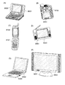
本発明に係る発光素子を含む画素領域を備えた表示装置を用いた電子機器として、テレビジョン装置(テレビ、テレビジョン受信機)、デジタルカメラ、デジタルビデオカメラ、携帯電話装置(携帯電話機)、PDA等の携帯情報端末、携帯型ゲーム機、モニタ、コンピュータ、カーオーディオ等の音響再生装置、家庭用ゲーム機等の記録媒体を備えた画像再生装置等が挙げられる。その具体例について、図7を参照して説明する。 As an electronic device using a display device including a pixel region including a light emitting element according to the present invention, a television device (television, television receiver), a digital camera, a digital video camera, a mobile phone device (mobile phone), a PDA Such as a portable information terminal such as a portable game machine, a monitor, a computer, an audio reproducing device such as a car audio, and an image reproducing device equipped with a recording medium such as a home game machine. A specific example will be described with reference to FIG.
図7(A)に示す本発明の表示装置を用いた携帯情報端末は、本体9201、表示部9202等を含み、本発明により高精細な画像を表示することができる。図7(B)に示す本発明の表示装置を用いたデジタルビデオカメラは、表示部9701、9702等を含み、本発明により高精細な画像を表示することができる。図7(C)に示す本発明の表示装置を用いた携帯端末は、本体9101、表示部9102等を含み、本発明により高精細な画像を表示することができる。図7(D)に示す本発明の表示装置を用いた携帯型のテレビジョン装置は、本体9301、表示部9302等を含み、本発明により高精細な画像を表示することができる。図7(E)に示す本発明の表示装置を用いた携帯型のコンピュータは、本体9401、表示部9402等を含み、本発明により高精細な画像を表示することができる。図7(F)に示す本発明の表示装置を用いたテレビジョン装置は、本体9501、表示部9502等を含み、本発明により高精細な画像を表示することができる。また、上記実施例のように、遮光性を有する層間絶縁膜又は遮光性を有する隔壁層を設けた場合には、不要光による影響を抑制することができるために、偏光板が不要となり、小型化、軽量化、薄型化が実現される。
A portable information terminal using the display device of the present invention illustrated in FIG. 7A includes a
ここで、上記テレビジョン装置の主要な構成について、図8のブロック図を用いて簡単に説明する。図中、EL表示パネル701は、本発明に係る表示装置を用いて作製されており、さらにEL表示パネル701と外部回路との接続方法として、(1)表示パネルの画素部と走査線側駆動回路703を基板上に一体形成し、さらに信号線側駆動回路702を別途ドライバICとして実装する場合、(2)表示パネルの画素部のみが形成されて走査線側駆動回路703と信号線側駆動回路702とがTAB方式により実装される場合、(3)表示パネルの画素部とその周辺に走査線側駆動回路703と信号線側駆動回路702とがCOG方式により実装される場合、などがあるが、どのような形態としても良い。
Here, the main configuration of the television apparatus will be briefly described with reference to the block diagram of FIG. In the figure, an
その他の外部回路の構成として、映像信号の入力側では、チューナ704で受信した信号のうち、映像信号を増幅する映像波増幅回路705と、そこから出力される信号を赤、緑、青の各色に対応した色信号に変換する映像信号処理回路706と、その映像信号をドライバICの入力仕様に変換するためのコントロール回路707などからなっている。コントロール回路707は、走査線側と信号線側にそれぞれ信号が出力する。デジタル駆動する場合には、信号線側に信号分割回路708を設け、入力デジタル信号をm個に分割して供給する構成としても良い。
As other external circuit configurations, on the input side of the video signal, among the signals received by the
チューナ704で受信した信号のうち、音声信号は、音声波増幅回路709に送られ、その出力は音声信号処理回路710を経てスピーカ713に供給される。制御回路711は受信局(受信周波数)や音量の制御情報を入力部712から受け、チューナ704や音声信号処理回路710に信号を送出する。
Of the signals received by the
このような外部回路と、EL表示パネルを筐体に組みこんで、図7(F)に示すようなテレビ受像機を完成させることができる。勿論、本発明はテレビ受像機に限定されず、パーソナルコンピュータのモニタをはじめ、鉄道の駅や空港などにおける情報表示盤や、街頭における広告表示盤など特に大面積の表示媒体として様々な用途に適用することができる。なお、本実施例は、上記実施の形態又は他の実施例と自由に組み合わせることができる。 A television receiver as shown in FIG. 7F can be completed by incorporating such an external circuit and an EL display panel in a housing. Of course, the present invention is not limited to a television receiver, and is applied to various uses as a display medium of a particularly large area such as a monitor of a personal computer, an information display board in a railway station or airport, an advertisement display board in a street, etc. can do. Note that this embodiment can be freely combined with the above embodiment mode or other embodiments.
本発明に係る表示装置は、メモリや処理回路などの機能回路やアンテナコイルを搭載することで、非接触でデータの送受信が可能なIDカードとして用いることができる。そのようなIDカードの構成の一例について図面を参照して説明する。 The display device according to the present invention can be used as an ID card capable of transmitting and receiving data without contact by mounting a functional circuit such as a memory or a processing circuit or an antenna coil. An example of the configuration of such an ID card will be described with reference to the drawings.
図9(A)に、本発明に係る表示装置を内蔵したIDカードの一形態を示す。図9(A)に示すIDカードは、非接触で端末装置のリーダ/ライタとデータの送受信を行う非接触型である。801はカード本体であり、802はカード本体801に搭載されている表示装置の画素部に相当する。 FIG. 9A shows one mode of an ID card incorporating a display device according to the present invention. The ID card shown in FIG. 9A is a non-contact type that transmits and receives data with a reader / writer of a terminal device in a non-contact manner. Reference numeral 801 denotes a card body, and 802 corresponds to a pixel portion of a display device mounted on the card body 801.
図9(B)に、図9(A)に示したカード本体801に含まれるカード基板803の構成を示す。カード基板803には、薄膜の半導体膜で形成されたIDチップ804と、上記実施の形態又は実施例に係る表示装置805とが貼り合わされている。IDチップ804と表示装置805は共に別途用意された基板上において形成された後、カード基板803上に転写されたものである。転写方法としては、多数のTFTからなる薄膜集積回路を作製した後、小型真空ピンセット等を用いて、貼り付ける方法や、UV光照射法を用いて選択的に貼り付ける方法などがある。また、表示装置における画素部や駆動回路部についても、同様に行うことができる。IDチップ804と表示装置805とを含む、薄膜の半導体膜を用いて形成され、なおかつ形成後にカード基板に転写される部分を、薄膜部807と呼ぶ。 FIG. 9B shows a configuration of the card substrate 803 included in the card main body 801 shown in FIG. An ID chip 804 formed of a thin semiconductor film and a display device 805 according to the above embodiment or example are attached to the card substrate 803. Both the ID chip 804 and the display device 805 are formed on a separately prepared substrate and then transferred onto the card substrate 803. As a transfer method, there are a method in which a thin film integrated circuit including a large number of TFTs is manufactured and then attached using small vacuum tweezers or the like, or a method of selectively attaching using a UV light irradiation method. The same can be applied to the pixel portion and the driver circuit portion in the display device. A portion formed using a thin semiconductor film including the ID chip 804 and the display device 805 and transferred to the card substrate after the formation is referred to as a thin film portion 807.
またカード基板803には、TFTを用いて作製された集積回路806が実装されている。集積回路806の実装の仕方は、特に限定されるものではなく、公知のCOG方法やワイヤボンディング方法、或いはTAB方法などを用いることができる。集積回路806は、薄膜部807と、カード基板803に形成された配線808を介して電気的に接続されている。 An integrated circuit 806 manufactured using a TFT is mounted on the card substrate 803. The method for mounting the integrated circuit 806 is not particularly limited, and a known COG method, wire bonding method, TAB method, or the like can be used. The integrated circuit 806 is electrically connected to the thin film portion 807 via a wiring 808 formed on the card substrate 803.
またカード基板803上には、集積回路806と電気的に接続されたアンテナコイル809が形成されている。アンテナコイル809により、端末装置との間のデータの送受信を、電磁誘導を用いて非接触で行うことができるので、非接触型のIDカードは接触型に比べてIDカードが物理的な磨耗による損傷を受けにくい。さらに非接触型のIDカードは、非接触にて情報の管理を行うタグ(無線タグ)としても用いることができる。非接触型のIDカードは、同じく非接触で情報の読み取りができるバーコードに比べて、管理可能な情報量が飛躍的に高い。また情報を読み取ることができる端末装置との間の距離を、バーコードを用いた場合に比べて長くすることができる。 An antenna coil 809 that is electrically connected to the integrated circuit 806 is formed over the card substrate 803. Since the antenna coil 809 can transmit and receive data to and from the terminal device in a non-contact manner using electromagnetic induction, the non-contact type ID card is physically worn compared to the contact type. Not easily damaged. Furthermore, the non-contact type ID card can also be used as a tag (wireless tag) for managing information without contact. A non-contact type ID card has a remarkably high amount of information that can be managed compared to a barcode that can also read information without contact. In addition, the distance from the terminal device that can read information can be made longer than when a barcode is used.
なお図9(B)では、アンテナコイル809をカード基板803上に形成した例を示しているが、別途作製しておいたアンテナコイルをカード基板803に実装するようにしても良い。例えば銅線などをコイル状に巻き、100μm程度の厚さを有する2枚のプラスチックフィルムの間に該銅線を挟んでプレスしたものを、アンテナコイルとして用いることができる。また、薄膜集積回路の中に、アンテナコイルを作りこんでおいても良い。また、図9(B)では、1つのIDカードにアンテナコイル809が1つだけ用いられているが、アンテナコイル809が複数用いられていても良い。 Note that FIG. 9B illustrates an example in which the antenna coil 809 is formed over the card substrate 803; however, an antenna coil that is separately manufactured may be mounted over the card substrate 803. For example, a coil formed by winding a copper wire or the like and sandwiching the copper wire between two plastic films having a thickness of about 100 μm can be used as an antenna coil. An antenna coil may be built in the thin film integrated circuit. In FIG. 9B, only one antenna coil 809 is used for one ID card, but a plurality of antenna coils 809 may be used.
なお、図9では表示装置805を搭載したIDカードの形態を示しているが、この構成に限定されるものではなく、必ずしも表示装置を設ける必要はない。ただし、表示装置を設けることで、顔写真のデータを表示装置において表示させることができ、印刷法を用いた場合に比べて顔写真のすり替えを困難にすることができる。また顔写真以外の情報を表示することができ、IDカードの高機能化を実現することができる。 Note that although FIG. 9 illustrates an ID card mounted with a display device 805, the present invention is not limited to this configuration, and a display device is not necessarily provided. However, by providing the display device, the face photo data can be displayed on the display device, and the face photo replacement can be made more difficult than when the printing method is used. In addition, information other than the face photo can be displayed, and the ID card can be enhanced.
なお、カード基板803には、可撓性を有するプラスチック基板を用いることができる。プラスチック基板としては、極性基のついたノルボルネン樹脂からなるARTON:JSR製を用いることができる。また、ポリエチレンテレフタレート(PET)、ポリエーテルスルホン(PES)、ポリエチレンナフタレート(PEN)、ポリカーボネート(PC)、ナイロン、ポリエーテルエーテルケトン(PEEK)、ポリスルホン(PSF)、ポリエーテルイミド(PEI)、ポリアリレート(PAR)、ポリブチレンテレフタレート(PBT)、ポリイミドなどのプラスチック基板を用いることができる。 Note that a flexible plastic substrate can be used for the card substrate 803. As the plastic substrate, ARTON: JSR made of norbornene resin with a polar group can be used. Polyethylene terephthalate (PET), polyethersulfone (PES), polyethylene naphthalate (PEN), polycarbonate (PC), nylon, polyetheretherketone (PEEK), polysulfone (PSF), polyetherimide (PEI), poly A plastic substrate such as arylate (PAR), polybutylene terephthalate (PBT), or polyimide can be used.
なお、本実施例では、IDチップと薄膜集積回路との間の電気的な接続は、図9において示した形態に限定されない。例えば、カード基板上に形成された配線を介すのではなく、IDチップの端子と薄膜集積回路の端子とを異方性の導電性樹脂やハンダなどで直接接続するようにしても良い。また図9において、薄膜集積回路と、カード基板に形成された配線との間の接続は、ワイヤボンディング法、ソルダーボールを用いたフリップチップ法で接続しても良いし、異方性の導電性樹脂やハンダなどで直接接続しても良いし、その他の方法を用いて接続しても良い。また、本発明に係る表示装置は、IDカードのみならず、IDタグ、無線チップ、無線タグ等の半導体装置に組み込んで使用することもできる。 In this embodiment, the electrical connection between the ID chip and the thin film integrated circuit is not limited to the form shown in FIG. For example, the terminal of the ID chip and the terminal of the thin film integrated circuit may be directly connected with an anisotropic conductive resin or solder instead of via the wiring formed on the card substrate. Further, in FIG. 9, the connection between the thin film integrated circuit and the wiring formed on the card substrate may be connected by a wire bonding method, a flip chip method using a solder ball, or anisotropic conductive property. It may be directly connected with resin or solder, or may be connected using other methods. The display device according to the present invention can be used by being incorporated in a semiconductor device such as an ID tag, a wireless chip, and a wireless tag as well as an ID card.
上述した本発明の発光素子は、表示機能を有する発光装置の画素部や、照明機能を有する発光装置の照明部に適用することができる。本実施例では、表示機能を有する発光装置の回路構成および駆動方法について図10〜13を用いて説明する。 The light-emitting element of the present invention described above can be applied to a pixel portion of a light-emitting device having a display function and an illumination portion of a light-emitting device having a lighting function. In this embodiment, a circuit configuration and a driving method of a light-emitting device having a display function will be described with reference to FIGS.
図10は本発明を適用した発光装置を上面からみた模式図である。図10において、基板6500上には、画素部6511と、ソース信号線駆動回路6512と、書込用ゲート信号線駆動回路6513と、消去用ゲート信号線駆動回路6514とが設けられている。ソース信号線駆動回路6512と、書込用ゲート信号線駆動回路6513と、消去用ゲート信号線駆動回路6514とは、それぞれ、配線群を介して、外部入力端子であるFPC(フレキシブルプリントサーキット)6503と接続している。そして、ソース信号線駆動回路6512と、書込用ゲート信号線駆動回路6513と、消去用ゲート信号線駆動回路6514とは、それぞれ、FPC6503からビデオ信号、クロック信号、スタート信号、リセット信号等を受け取る。またFPC6503にはプリント配線基盤(PWB)6504が取り付けられている。なお、駆動回路部は、上記のように必ずしも画素部6511と同一基板上に設けられている必要はなく、例えば、配線パターンが形成されたFPC上にICチップを実装したもの(TCP)等を利用し、基板外部に設けられていてもよい。
FIG. 10 is a schematic view of a light emitting device to which the present invention is applied as viewed from above. In FIG. 10, a
画素部6511には、列方向に延びた複数のソース信号線が行方向に並んで配列している。また、電流供給線が行方向に並んで配列している。また、画素部6511には、行方向に延びた複数のゲート信号線が列方向に並んで配列している。また画素部6511には、発光素子を含む一組の回路が複数配列している。
In the
図11は、一画素を動作するための回路を表した図である。図11に示す回路には、第1のトランジスタ901と第2のトランジスタ902と発光素子903とが含まれている。第1のトランジスタ901と、第2のトランジスタ902とは、それぞれ、ゲート電極と、ドレイン領域と、ソース領域とを含む三端子の素子であり、ドレイン領域とソース領域の間にチャネル領域を有する。ここで、ソース領域とドレイン領域とは、トランジスタの構造や動作条件等によって変わるため、いずれがソース領域またはドレイン領域であるかを限定することが困難である。そこで、本形態においては、ソースまたはドレインとして機能する領域を、それぞれ第1電極、第2電極と表記する。
FIG. 11 is a diagram illustrating a circuit for operating one pixel. The circuit illustrated in FIG. 11 includes a
ゲート信号線911と、書込用ゲート信号線駆動回路913とはスイッチ918によって電気的に接続または非接続の状態になるように設けられている。また、ゲート信号線911と、消去用ゲート信号線駆動回路914とはスイッチ919によって電気的に接続または非接続の状態になるように設けられている。また、ソース信号線912は、スイッチ920によってソース信号線駆動回路915または電源916のいずれかに電気的に接続するように設けられている。そして、第1のトランジスタ901のゲートはゲート信号線911に電気的に接続している。また、第1のトランジスタ901の第1電極はソース信号線912に電気的に接続し、第2電極は第2のトランジスタ902のゲート電極と電気的に接続している。第2のトランジスタ902の第1電極は電流供給線917と電気的に接続し、第2電極は発光素子903に含まれる一の電極と電気的に接続している。なお、スイッチ918は、書込用ゲート信号線駆動回路913に含まれていてもよい。またスイッチ919についても消去用ゲート信号線駆動回路914の中に含まれていてもよい。また、スイッチ920についてもソース信号線駆動回路915の中に含まれていてもよい。
The
また画素部におけるトランジスタや発光素子等の配置について特に限定はないが、例えば図12の上面図に表すように配置することができる。図12において、第1のトランジスタ1001の第1電極はソース信号線1004に接続し、第2の電極は第2のトランジスタ1002のゲート電極に接続している。また第2のトランジスタ1002の第1電極は電流供給線1005に接続し、第2電極は発光素子の電極1006に接続している。ゲート信号線1003の一部は第1のトランジスタ1001のゲート電極として機能する。
There is no particular limitation on the arrangement of transistors, light-emitting elements, and the like in the pixel portion. For example, they can be arranged as shown in the top view of FIG. In FIG. 12, the first electrode of the
次に、駆動方法について説明する。図13は時間経過に伴ったフレームの動作について説明する図である。図13において、横方向は時間経過を表し、縦方向はゲート信号線の走査段数を表している。 Next, a driving method will be described. FIG. 13 is a diagram for explaining the operation of a frame over time. In FIG. 13, the horizontal direction represents the passage of time, and the vertical direction represents the number of scanning stages of the gate signal line.
本発明の発光装置を用いて画像表示を行うとき、表示期間においては、画面の書き換え動作と表示動作とが繰り返し行われる。この書き換え回数について特に限定はないが、画像をみる人がちらつき(フリッカ)を感じないように少なくとも1秒間に60回程度とすることが好ましい。ここで、一画面(1フレーム)の書き換え動作と表示動作を行う期間を1フレーム期間という。 When image display is performed using the light emitting device of the present invention, the screen rewriting operation and the display operation are repeatedly performed during the display period. The number of rewrites is not particularly limited, but is preferably at least about 60 times per second so that a person viewing the image does not feel flicker. Here, a period during which one screen (one frame) is rewritten and displayed is referred to as one frame period.
1フレームは、図13に示すように、書き込み期間501a、502a、503a、504aと保持期間501b、502b、503b、504bとを含む4つのサブフレーム501、502、503、504に時分割されている。発光するための信号を与えられた発光素子は、保持期間において発光状態となっている。各々のサブフレームにおける保持期間の長さの比は、第1のサブフレーム501:第2のサブフレーム502:第3のサブフレーム503:第4のサブフレーム504=23:22:21:20=8:4:2:1となっている。これによって4ビット階調を表現することができる。但し、ビット数及び階調数はここに記すものに限定されず、例えば8つのサブフレームを設け8ビット階調を行えるようにしてもよい。
As shown in FIG. 13, one frame is time-divided into four
1フレームにおける動作について説明する。まず、サブフレーム501において、1行目から最終行まで順に書き込み動作が行われる。従って、行によって書き込み期間の開始時間が異なる。書き込み期間501aが終了した行から順に保持期間501bへと移る。当該保持期間において、発光するための信号を与えられている発光素子は発光状態となっている。また、保持期間501bが終了した行から順に次のサブフレーム502へ移り、サブフレーム501の場合と同様に1行目から最終行まで順に書き込み動作が行われる。以上のような動作を繰り返し、サブフレーム504の保持期間504b迄終了する。サブフレーム504における動作を終了したら次のフレームへ移る。このように、各サブフレームにおいて発光した時間の積算時間が、1フレームにおける各々の発光素子の発光時間となる。この発光時間を発光素子ごとに変えて一画素内で様々に組み合わせることによって、明度および色度の異なる様々な表示色を形成することができる。
An operation in one frame will be described. First, in the
サブフレーム504のように、最終行目までの書込が終了する前に、既に書込を終え、保持期間に移行した行における保持期間を強制的に終了させたいときは、保持期間504bの後に消去期間504cを設け、強制的に非発光の状態となるように制御することが好ましい。そして、強制的に非発光状態にした行については、一定期間、非発光の状態を保つ(この期間を非発光期間504dとする。)。そして、最終行目の書込期間が終了したら直ちに、一行目から順に次の(またはフレーム)の書込期間に移行する。なお、このようにある行の画素では書き込みを行い、またある行の画素には画素を非発光の状態にする消去信号を入力するには、図15に示すように、1水平期間を2つに分割し、一方の期間を書き込みにあて、他方の期間を消去にあてる。分割された水平期間内で、各々のゲート信号線911を選択し、そのときに対応する信号をソース信号線912に入力する。例えば、ある1水平期間において、前半はi行目を選択し、後半はj行目を選択する。すると、1水平期間において、あたかも同時に2行分を選択したかのように動作させることが可能となる。つまり、それぞれの1水平期間の書き込み期間を用いて、書き込み期間501a〜504aに画素へ映像信号を書き込む。そして、このときの1水平期間の消去期間には画素を選択しない。また、別の1水平期間の消去期間を用いて消去期間504cに画素へ書き込まれた信号を消去する。このときの1水平期間の書き込み期間には画素を選択しない。これによって、開口率の高い画素を有する表示装置を提供することができ、歩留まりの向上を図ることができる。
When it is desired to forcibly end the holding period in the row that has already finished writing and has shifted to the holding period before the writing up to the last row is completed as in the
なお、本実施例では、サブフレーム501乃至504は保持期間の長いものから順に並んでいるが、必ずしも本実施例のような並びにする必要はなく、例えば保持期間の短いものから順に並べられていてもよいし、または保持期間の長いものと短いものとがランダムに並んでいてもよい。また、サブフレームは、さらに複数のフレームに分割されていてもよい。つまり、同じ映像信号を与えている期間、ゲート信号線の走査を複数回行ってもよい。
In this embodiment, the
ここで、書込期間および消去期間における、図11で示す回路の動作について説明する。まず書込期間における動作について説明する。書込期間において、i行目(iは自然数)のゲート信号線911は、スイッチ918を介して書込用ゲート信号線駆動回路913と電気的に接続し、消去用ゲート信号線駆動回路914とは非接続である。また、ソース信号線912はスイッチ920を介してソース信号線駆動回路915と電気的に接続している。ここで、i行目のゲート信号線911に接続した第1のトランジスタ901のゲートに信号が入力され、第1のトランジスタ901はオンとなる。そして、この時、1列目から最終列目迄のソース信号線に同時に映像信号が入力される。なお、各列のソース信号線912から入力される映像信号は互いに独立したものである。ソース信号線912から入力された映像信号は、各々のソース信号線に接続した第1のトランジスタ901を介して第2のトランジスタ902のゲート電極に入力される。この時、第2のトランジスタ902のゲート電極に入力された信号によって、第2のトランジスタ902のオンオフが制御される。そして、第2のトランジスタ902がオンすると発光素子903に電圧が印加され、発光素子903に電流が流れる。つまり、第2のトランジスタ902のゲート電極に入力する信号によって、発光素子903の発光又は非発光が決まる。例えば、第2のトランジスタ902がPチャネル型である場合は、第2のトランジスタ902のゲート電極にLow Levelの信号が入力されることによって発光素子903が発光する。一方、第2のトランジスタ902がNチャネル型である場合は、第2のトランジスタ902のゲート電極にHigh Levelの信号が入力されることによって発光素子903が発光する。
Here, the operation of the circuit shown in FIG. 11 in the writing period and the erasing period will be described. First, the operation in the writing period will be described. In the write period, the i-th (i is a natural number)
次に消去期間における動作について説明する。消去期間において、j行目(jは自然数)のゲート信号線911は、スイッチ919を介して消去用ゲート信号線駆動回路914と電気的に接続し、書込用ゲート信号線駆動回路913とは非接続である。また、ソース信号線912はスイッチ920を介して電源916と電気的に接続している。ここで、j行目のゲート信号線911に接続した第1のトランジスタ901のゲートに信号が入力され、第1のトランジスタ901はオンとなる。そして、この時、1列目から最終列目迄のソース信号線に同時に消去信号が入力される。ソース信号線912から入力された消去信号は、各々のソース信号線に接続した第1のトランジスタ901を介して第2のトランジスタ902のゲート電極に入力される。この時第2のトランジスタ902のゲート電極に入力された消去信号によって、第2のトランジスタ902はオフし、電流供給線917から発光素子903への電流の供給が阻止される。そして、発光素子903は強制的に非発光となる。例えば、第2のトランジスタ902がPチャネル型である場合は、第2のトランジスタ902のゲート電極にHigh Levelの信号が入力されることによって発光素子903は非発光となる。一方、第2のトランジスタ902がNチャネル型である場合は、第2のトランジスタ902のゲート電極にLow Levelの信号が入力されることによって発光素子903は非発光となる。
Next, the operation in the erasing period will be described. In the erasing period, the
なお、消去期間では、j行目については、以上に説明したような動作によって消去する為の信号を入力する。しかし、前述のように、j行目が消去期間であると共に、他の行(i行目とする。)については書込期間となる場合がある。このような場合、同じ列のソース信号線を利用してj行目には消去の為の信号を、i行目には書込の為の信号を入力する必要があるため、以下に説明するような動作をさせることが好ましい。 In the erasing period, a signal for erasing the j-th row is input by the operation as described above. However, as described above, the j-th row may be an erasing period, and the other rows (i-th row) may be a writing period. In such a case, it is necessary to input a signal for erasure to the j-th row and a signal for writing to the i-th row by using the source signal line in the same column, and will be described below. It is preferable to perform such an operation.
消去期間における動作によって、j−1行目の発光素子903が非発光となった後、直ちに、ゲート信号線911と消去用ゲート信号線駆動回路914とを非接続の状態とすると共に、スイッチ920を切り替えてソース信号線912とソース信号線駆動回路915と接続させる。そして、ソース信号線912とソース信号線駆動回路915とを接続させると共に、スイッチ918を切り替えてゲート信号線911と書込用ゲート信号線駆動回路913とを接続させる。そして、書込用ゲート信号線駆動回路913からi行目のゲート信号線911に選択的に信号が入力され、第1のトランジスタ901がオンすると共に、ソース信号線駆動回路915からは、1列目から最終列目迄のソース信号線912に書込の為の映像信号が入力される。この映像信号によって、i行目の発光素子903は、発光または非発光となる。
The
以上のようにしてi行目について書込期間を終えたら、直ちに、j行目の消去期間に移行する。その為にスイッチ918を切り替えて、ゲート信号線と書込用ゲート信号線駆動回路913を非接続とすると共に、スイッチ920を切り替えてソース信号線を電源916と接続する。また、ゲート信号線911と書込用ゲート信号線駆動回路913を非接続とすると共に、ゲート信号線911については、スイッチ919を切り替えて消去用ゲート信号線駆動回路914と接続状態にする。そして、消去用ゲート信号線駆動回路914からj行目のゲート信号線911に選択的に信号を入力して第1のトランジスタ901がオンすると共に、電源916から消去信号が入力される。そして、消去信号により、発光素子903は強制的に非発光となる。このようにして、j行目の消去期間を終えたら、直ちに、i+1行目の書込期間に移行する。以下、同様に、消去期間と書込期間とを繰り返し、最終行目の消去期間まで動作させればよい。
Immediately after the writing period for the i-th row is completed as described above, the erasing period for the j-th row is started. For this purpose, the switch 918 is switched to disconnect the gate signal line and the write gate signal
なお、本形態では、j−1行目の消去期間とj行目の消去期間との間にi行目の書込期間を設ける態様について説明したが、これに限らず、j行目の消去期間とj+1行目の消去期間との間にi行目の書込期間を設けてもよい。 In this embodiment, the mode in which the writing period of the i-th row is provided between the erasing period of the (j−1) -th row and the erasing period of the j-th row has been described. An i-th writing period may be provided between the period and the (j + 1) -th erasing period.
また、本形態では、サブフレーム504のように非発光期間504dを設ける場合において、消去用ゲート信号線駆動回路914と或る一のゲート信号線とを非接続状態にすると共に、書込用ゲート信号線駆動回路913と他のゲート信号線とを接続状態にする動作を繰り返している。このような動作は、特に非発光期間を設けないフレームにおいて行っても構わない。なお、本実施例は、上記実施の形態又は他の実施例と自由に組み合わせることができる。
In this embodiment, when the
本発明に係る発光素子は、画素電極と対向電極の間に複数の発光層を有するEL素子において、各発光層の間に中間導電層を設け、かつ中間導電層(複数の中間導電層が設けられる場合においては、それらの少なくとも一の中間導電層)において、正孔注入又は電子注入を担う層のいずれかが、膜状ではなく、島状に形成されていることを特徴とする。このような構造を採用することによって、中間導電層の電子(又は正孔)を注入する層に関し、材料の透明性を一切考慮する必要が無い、発光層からの発光は、中間導電層によって殆んど吸収されることが無い、中間導電層の材料の結晶性も考慮する必要が無い、素子の作製時間が短縮される等の、様々な効果を生み出すことができる。 The light-emitting element according to the present invention is an EL element having a plurality of light-emitting layers between a pixel electrode and a counter electrode. An intermediate conductive layer is provided between each light-emitting layer, and an intermediate conductive layer (a plurality of intermediate conductive layers are provided). In such a case, in at least one of the intermediate conductive layers, one of the layers responsible for hole injection or electron injection is formed in an island shape instead of a film shape. By adopting such a structure, there is no need to consider the transparency of the material for the layer injecting electrons (or holes) in the intermediate conductive layer. Various effects can be produced, such as the fact that the material is hardly absorbed, the crystallinity of the material of the intermediate conductive layer does not need to be considered, and the device manufacturing time is shortened.
また、上記作用効果を有する発光素子はELディスプレイに代表される表示装置に採用することができる。該表示装置は、互いに直交するように設けられた2種類のストライプ状電極の間に発光層及び中間導電層を形成する方式(単純マトリクス方式)、又はTFTに接続されマトリクス状に配列された画素電極と対向電極との間に発光層及び中間導電層を形成する方式(アクティブマトリクス方式)の2種類に大別されるが、本発明に係る発光素子は、単純マトリクス方式とアクティブマトリクス方式のいずれにも適用することができる。また、上記表示装置は、あらゆる電子機器やIDカード等のユビキタス製品に搭載することができ、本発明の利用可能性は極めて多岐に渡る。 In addition, the light-emitting element having the above-described effects can be used for a display device typified by an EL display. The display device includes a method in which a light emitting layer and an intermediate conductive layer are formed between two types of stripe electrodes provided so as to be orthogonal to each other (simple matrix method), or pixels connected to TFTs and arranged in a matrix. The light-emitting element according to the present invention is classified into either a simple matrix method or an active matrix method, which is roughly classified into two types (active matrix method) in which a light emitting layer and an intermediate conductive layer are formed between an electrode and a counter electrode. It can also be applied to. Further, the display device can be mounted on any electronic device or ubiquitous product such as an ID card, and the applicability of the present invention is extremely diverse.
11:陽極
12:陰極
13:中間導電層(Alq:Li層)
14:中間導電層(In−Zn−O(インジウム・亜鉛酸化物)層)
15:有機層
16:有機層
17:層間絶縁膜
101:基板
102:陽極
103:第1の発光層
104:電子注入を担う層
105:正孔注入を担う層
106:第2の発光層
107:陰極
108:第3の発光層
203:1番目の発光層
204:1番目の電子注入を担う層
205:1番目の正孔注入を担う層
206:2番目の発光層
207:k番目の発光層
208:k番目の電子注入を担う層
209:k番目の正孔注入を担う層
210:k+1番目の発光層
211:n−1番目の電子注入を担う層
212:n−1番目の正孔注入を担う層
213:n番目の発光層
310:画素
311:トランジスタ
312:トランジスタ
313:発光素子
316:容量素子
317:第1の電源
318:第2の電源
340:トランジスタ
341:トランジスタ
342:トランジスタ
343:電源
400:発光領域
401:ゲートドライバ
402:ゲートドライバ
403:ソースドライバ
405:基板
406:対向基板
407:接続フィルム
408:シール材
409:隔壁層
410:素子群
411:第1の層間絶縁膜
412:第2の層間絶縁膜
414:配線
415:透光性樹脂
416:遮光性を有する隔壁層
417:遮光性を有する層間絶縁膜
418:空間
501:サブフレーム
501a:書き込み期間
501b:保持期間
502:サブフレーム
502a:書き込み期間
502b:保持期間
503:サブフレーム
503a:書き込み期間
503b:保持期間
504:サブフレーム
504a:書き込み期間
504b:保持期間
504c:消去期間
504d:非発光期間
600:Mo
601:アルミニウムを含む合金
602:ITO
603:アルミニウムを含む合金
604:アルミニウムを含む合金
605:ITO
606:アルミニウムを含む合金
607:ニッケルシリサイド
608:シリコン半導体層
801:カード本体
803:カード基板
804:IDチップ
805:表示装置
806:集積回路
807:薄膜部
808:配線
809:アンテナコイル
701:EL表示パネル
702:信号線側駆動回路
703:走査線側駆動回路
704:チューナ
705:映像波増幅回路
706:映像信号処理回路
707:コントロール回路
708:信号分割回路
709:音声波増幅回路
710:音声信号処理回路
711:制御回路
712:入力部
713:スピーカ
901:第1のトランジスタ
902:第2のトランジスタ
903:発光素子
911:ゲート信号線
912:ソース信号線
913:書込用ゲート信号線駆動回路
914:消去用ゲート信号線駆動回路
915:ソース信号線駆動回路
916:電源
917:電流供給線
918:スイッチ
919:スイッチ
920:スイッチ
1001:第1のトランジスタ
1002:第2のトランジスタ
1003:ゲート信号線
1004:ソース信号線
1005:電流供給線
1006:発光素子の電極
6500:基板
6503:FPC(フレキシブルプリントサーキット)
6504:プリント配線基盤(PWB)
6511:画素部
6512:ソース信号線駆動回路
6513:書込用ゲート信号線駆動回路
6514:消去用ゲート信号線駆動回路
9101:本体
9102:表示部
9201:本体
9202:表示部
9301:本体
9302:表示部
9401:本体
9402:表示部
9501:本体
9502:表示部
9701:表示部
9702:表示部
11: Anode 12: Cathode 13: Intermediate conductive layer (Alq: Li layer)
14: Intermediate conductive layer (In-Zn-O (indium / zinc oxide) layer)
15: Organic layer 16: Organic layer 17: Interlayer insulating film 101: Substrate 102: Anode 103: First light emitting layer 104: Layer responsible for electron injection 105: Layer responsible for hole injection 106: Second light emitting layer 107: Cathode 108: third light-emitting layer 203: first light-emitting layer 204: layer responsible for first electron injection 205: layer responsible for first hole injection 206: second light-emitting layer 207: k-th light-emitting layer 208: layer responsible for the kth electron injection 209: layer responsible for the kth hole injection 210: k + 1th light emitting layer 211: layer responsible for the (n−1) th electron injection 212: n−1th hole injection Layer 213: nth light emitting layer 310: pixel 311: transistor 312: transistor 313: light emitting element 316: capacitor 317: first power supply 318: second power supply 340: transistor 341: transistor 342: Transistor 343: Power source 400: Light emitting region 401: Gate driver 402: Gate driver 403: Source driver 405: Substrate 406: Counter substrate 407: Connection film 408: Sealing material 409: Partition layer 410: Element group 411: First interlayer insulation Film 412: Second interlayer insulating film 414: Wiring 415: Translucent resin 416: Light shielding partition layer 417: Light shielding interlayer insulating film 418: Space 501: Subframe 501 a: Writing period 501 b: Holding period 502: Subframe 502a: Writing period 502b: Holding period 503: Subframe 503a: Writing period 503b: Holding period 504: Subframe 504a: Writing period 504b: Holding period 504c: Erase period 504d: Non-light emitting period 600: Mo
601: Alloy containing aluminum 602: ITO
603: Alloy containing aluminum 604: Alloy containing aluminum 605: ITO
606: Alloy containing aluminum 607: Nickel silicide 608: Silicon semiconductor layer 801: Card body 803: Card substrate 804: ID chip 805: Display device 806: Integrated circuit 807: Thin film portion 808: Wiring 809: Antenna coil 701: EL display Panel 702: Signal line side drive circuit 703: Scan line side drive circuit 704: Tuner 705: Video wave amplification circuit 706: Video signal processing circuit 707: Control circuit 708: Signal division circuit 709: Audio wave amplification circuit 710: Audio signal processing Circuit 711: Control circuit 712: Input unit 713: Speaker 901: First transistor 902: Second transistor 903: Light emitting element 911: Gate signal line 912: Source signal line 913: Write gate signal line drive circuit 914: Erase gate signal line drive circuit 915: Source signal line drive circuit 916: power supply 917: current supply line 918: switch 919: switch 920: switch 1001: first transistor 1002: second transistor 1003: gate signal line 1004: source signal line 1005: current supply line 1006:
6504: Printed wiring board (PWB)
6511: Pixel portion 6512: Source signal line drive circuit 6513: Write gate signal line drive circuit 6514: Erase gate signal line drive circuit 9101: Main body 9102: Display portion 9201: Main body 9202: Display portion 9301: Main body 9302: Display Unit 9401: main body 9402: display unit 9501: main body 9502: display unit 9701: display unit 9702: display unit
Claims (14)
前記第1の電極上の第1の発光層と、
前記第1の発光層上の中間導電層と、
前記中間導電層上の第2の発光層と、
前記第2の発光層上の第2の電極と、を有し、
前記中間導電層は電子注入を担う層と、前記電子注入を担う層と接する正孔注入を担う層とを含み、
前記電子注入を担う層と前記正孔注入を担う層の少なくとも一方は島状の層であり、
前記正孔注入を担う層は、酸化モリブデンと芳香族アミン類とを含む
ことを特徴とする発光素子。 A first electrode;
A first light emitting layer on the first electrode;
An intermediate conductive layer on the first light emitting layer;
A second light emitting layer on the intermediate conductive layer;
And a second electrode on the second light-emitting layer,
The intermediate conductive layer includes a layer responsible for electron injection and a layer responsible for hole injection in contact with the layer responsible for electron injection,
Ri least one island-like layers der layers responsible for the hole injection and the layer responsible for the electron injection,
The light-emitting element, wherein the layer responsible for hole injection includes molybdenum oxide and aromatic amines .
第2の電極と、を積層してなり、
前記中間導電層は電子注入を担う層と、前記電子注入を担う層と接する正孔注入層を担う層とを含み、
前記電子注入を担う層と前記正孔注入層を担う層の少なくとも一方は島状の層であり、
前記正孔注入を担う層は、酸化モリブデンと芳香族アミン類とを含む
ことを特徴とする発光素子。 A first electrode, a plurality of light emitting layers, a plurality of intermediate conductive layers sandwiched between the plurality of light emitting layers,
It will be the second electrode, the laminated,
The intermediate conductive layer includes a layer responsible for electron injection, and a layer responsible for a hole injection layer in contact with the layer responsible for electron injection,
Ri least one island-like layers der layers responsible for the hole injection layer and the layer which has the electron injection,
The light-emitting element, wherein the layer responsible for hole injection includes molybdenum oxide and aromatic amines .
k番目(kは、1≦k≦(n−1)なる整数)の発光層と(k+1)番目の発光層との間には、中間導電層が含まれ、
前記中間導電層には電子注入を担う層と、前記電子注入を担う層と接する正孔注入を担う層とを含み、
前記電子注入を担う層と前記正孔注入を担う層の少なくとも一方は島状の層であり、
前記正孔注入を担う層は、酸化モリブデンと芳香族アミン類とを含む
ことを特徴とする発光素子。 Between the first electrode and the second electrode, the first to nth (n is an integer of 2 or more) n light emitting layers are sequentially stacked,
An intermediate conductive layer is included between the kth (k is an integer 1 ≦ k ≦ (n−1)) light emitting layer and the (k + 1) th light emitting layer.
The intermediate conductive layer includes a layer responsible for electron injection, and a layer responsible for hole injection in contact with the layer responsible for electron injection,
Ri least one island-like layers der layers responsible for the hole injection and the layer responsible for the electron injection,
The light-emitting element, wherein the layer responsible for hole injection includes molybdenum oxide and aromatic amines .
前記電子注入を担う層は、Mg−Ag合金、Al−Li合金、Mg−Li合金、Ca3N2又はMg3N2を含むことを特徴とする発光素子。 In any one of Claim 1 thru | or 3,
The layer responsible for electron injection includes a Mg—Ag alloy, an Al—Li alloy, a Mg—Li alloy, Ca 3 N 2 or Mg 3 N 2 .
前記正孔注入を担う層が前記島状の層であることを特徴とする発光素子。The light-emitting element, wherein the layer responsible for hole injection is the island-shaped layer.
前記発光素子は、
第1の電極と、
前記第1の電極上の第1の発光層と、
前記第1の発光層上の中間導電層と、
前記中間導電層上の第2の発光層と、
前記第2の発光層上の第2の電極と、を有し、
前記中間導電層は電子注入を担う層と、前記電子注入を担う層と接する正孔注入を担う層を含み、
前記電子注入を担う層と前記正孔注入を担う層の少なくとも一方は島状の層であり、
前記正孔注入を担う層は、酸化モリブデンと芳香族アミン類とを含む
ことを特徴とする表示装置。 A transistor provided on a substrate; and a light-emitting element connected to the transistor through an interlayer insulating film;
The light emitting element is
A first electrode;
A first light emitting layer on the first electrode;
An intermediate conductive layer on the first light emitting layer;
A second light emitting layer on the intermediate conductive layer;
And a second electrode on the second light-emitting layer,
The intermediate conductive layer includes a layer responsible for electron injection and a layer responsible for hole injection in contact with the layer responsible for electron injection,
Ri least one island-like layers der layers responsible for the hole injection and the layer responsible for the electron injection,
The display device, wherein the layer responsible for hole injection includes molybdenum oxide and aromatic amines .
前記発光素子は、
第1の電極と、複数の発光層と、前記複数の発光層の間に挟まれた複数の中間導電層と、
第2の電極と、を積層してなり、
前記中間導電層は電子注入を担う層と、前記電子注入を担う層と接する正孔注入層を担う層とを含み、
前記電子注入を担う層と前記正孔注入層を担う層の少なくとも一方は島状の層であり、
前記正孔注入を担う層は、酸化モリブデンと芳香族アミン類とを含む
ことを特徴とする表示装置。 A transistor provided on a substrate; and a light-emitting element connected to the transistor through an interlayer insulating film;
The light emitting element is
A first electrode, a plurality of light emitting layers, a plurality of intermediate conductive layers sandwiched between the plurality of light emitting layers,
It will be the second electrode, the laminated,
The intermediate conductive layer includes a layer responsible for electron injection, and a layer responsible for a hole injection layer in contact with the layer responsible for electron injection,
Ri least one island-like layers der layers responsible for the hole injection layer and the layer which has the electron injection,
The display device, wherein the layer responsible for hole injection includes molybdenum oxide and aromatic amines .
前記発光素子は、
第1の電極と第2の電極の間に、1番目からn番目(nは2以上の整数)までのn個の発光層を順次積層してなり、
k番目(kは、1≦k≦(n−1)なる整数)の発光層と(k+1)番目の発光層との間には、中間導電層が含まれ、
前記中間導電層には電子注入を担う層と、前記電子注入を担う層と接する正孔注入を担う層とを含み、
前記電子注入を担う層と前記正孔注入を担う層の少なくとも一方は島状の層であり、
前記正孔注入を担う層は、酸化モリブデンと芳香族アミン類とを含む
ことを特徴とする表示装置。 A transistor provided on a substrate; and a light-emitting element connected to the transistor through an interlayer insulating film;
The light emitting element is
Between the first electrode and the second electrode, the first to nth (n is an integer of 2 or more) n light emitting layers are sequentially stacked,
An intermediate conductive layer is included between the kth (k is an integer 1 ≦ k ≦ (n−1)) light emitting layer and the (k + 1) th light emitting layer.
The intermediate conductive layer includes a layer responsible for electron injection, and a layer responsible for hole injection in contact with the layer responsible for electron injection,
Ri least one island-like layers der layers responsible for the hole injection and the layer responsible for the electron injection,
The display device, wherein the layer responsible for hole injection includes molybdenum oxide and aromatic amines .
前記電子注入を担う層は、Mg−Ag合金、Al−Li合金、Mg−Li合金、Ca3N2又はMg3N2を含むことを特徴とする表示装置。 In any one of Claims 6 thru | or 8,
The display device characterized in that the layer responsible for electron injection includes Mg—Ag alloy, Al—Li alloy, Mg—Li alloy, Ca 3 N 2 or Mg 3 N 2 .
前記正孔注入を担う層が前記島状の層であることを特徴とする表示装置。The display device, wherein the layer responsible for hole injection is the island-shaped layer.
前記層間絶縁膜は炭素を含み、かつ遮光性を有することを特徴とする表示装置。 In any one of Claims 6 thru | or 10,
The display device, wherein the interlayer insulating film contains carbon and has a light shielding property.
前記発光素子に接して、炭素を含み、かつ遮光性を有する隔壁層が設けられていることを特徴とする表示装置。 In any one of Claims 6 thru | or 11,
A display device comprising a partition layer containing carbon and having a light-shielding property in contact with the light-emitting element.
前記トランジスタと前記発光素子は、アルミニウム及びニッケルを含む合金からなる配線によって接続されていることを特徴とする表示装置。 In any one of Claim 6 thru | or 12,
The display device, wherein the transistor and the light emitting element are connected by a wiring made of an alloy containing aluminum and nickel.
前記トランジスタと前記発光素子は、アルミニウムと、ニッケルと、炭素を含む合金からなる配線によって接続されていることを特徴とする表示装置。 In any one of Claim 6 thru | or 12,
The display device, wherein the transistor and the light-emitting element are connected to each other by a wiring made of an alloy containing aluminum, nickel, and carbon.
Priority Applications (1)
| Application Number | Priority Date | Filing Date | Title |
|---|---|---|---|
| JP2005146844A JP4731996B2 (en) | 2004-05-20 | 2005-05-19 | Light emitting element and display device |
Applications Claiming Priority (3)
| Application Number | Priority Date | Filing Date | Title |
|---|---|---|---|
| JP2004151103 | 2004-05-20 | ||
| JP2004151103 | 2004-05-20 | ||
| JP2005146844A JP4731996B2 (en) | 2004-05-20 | 2005-05-19 | Light emitting element and display device |
Related Child Applications (1)
| Application Number | Title | Priority Date | Filing Date |
|---|---|---|---|
| JP2010225001A Division JP5005081B2 (en) | 2004-05-20 | 2010-10-04 | Light emitting element and display device |
Publications (3)
| Publication Number | Publication Date |
|---|---|
| JP2006005340A JP2006005340A (en) | 2006-01-05 |
| JP2006005340A5 JP2006005340A5 (en) | 2008-05-22 |
| JP4731996B2 true JP4731996B2 (en) | 2011-07-27 |
Family
ID=35773409
Family Applications (1)
| Application Number | Title | Priority Date | Filing Date |
|---|---|---|---|
| JP2005146844A Expired - Fee Related JP4731996B2 (en) | 2004-05-20 | 2005-05-19 | Light emitting element and display device |
Country Status (1)
| Country | Link |
|---|---|
| JP (1) | JP4731996B2 (en) |
Families Citing this family (10)
| Publication number | Priority date | Publication date | Assignee | Title |
|---|---|---|---|---|
| JP5057351B2 (en) * | 2007-11-13 | 2012-10-24 | 国立大学法人北陸先端科学技術大学院大学 | Organic EL device |
| KR101708847B1 (en) * | 2010-04-08 | 2017-02-22 | 삼성디스플레이 주식회사 | Organic light emitting diode display and method for manufacturing the same |
| JP5543441B2 (en) * | 2010-06-28 | 2014-07-09 | パナソニック株式会社 | ORGANIC LIGHT EMITTING ELEMENT AND ITS MANUFACTURING METHOD, ORGANIC DISPLAY PANEL, ORGANIC DISPLAY DEVICE |
| JP2012022787A (en) * | 2010-07-12 | 2012-02-02 | Seiko Epson Corp | Organic el device, method for manufacturing organic el device, and electronic apparatus |
| WO2013024787A1 (en) | 2011-08-12 | 2013-02-21 | パナソニック株式会社 | Organic electroluminescent element |
| JP6061581B2 (en) | 2012-09-19 | 2017-01-18 | ソニーセミコンダクタソリューションズ株式会社 | Display device |
| JP6247446B2 (en) * | 2013-02-26 | 2017-12-13 | 株式会社半導体エネルギー研究所 | Driving method of light emitting device |
| JP6235657B2 (en) * | 2016-07-08 | 2017-11-22 | ソニーセミコンダクタソリューションズ株式会社 | Display device |
| JP2017002410A (en) * | 2016-09-27 | 2017-01-05 | 大日本印刷株式会社 | Evaporation mask |
| KR102631177B1 (en) * | 2018-12-28 | 2024-01-29 | 엘지디스플레이 주식회사 | Electroluminance Lighting Device |
Family Cites Families (15)
| Publication number | Priority date | Publication date | Assignee | Title |
|---|---|---|---|---|
| JP3476035B2 (en) * | 1995-02-10 | 2003-12-10 | 出光興産株式会社 | Organic electroluminescence device |
| JP4354019B2 (en) * | 1997-04-18 | 2009-10-28 | 出光興産株式会社 | Organic electroluminescence device |
| JPH10255982A (en) * | 1997-03-06 | 1998-09-25 | Hokuriku Electric Ind Co Ltd | Organic electroluminescent(el) element |
| JP3571171B2 (en) * | 1997-05-08 | 2004-09-29 | 出光興産株式会社 | Organic electroluminescence device |
| JP3884564B2 (en) * | 1998-05-20 | 2007-02-21 | 出光興産株式会社 | Organic EL light emitting device and light emitting device using the same |
| JP2002093586A (en) * | 2000-09-19 | 2002-03-29 | Semiconductor Energy Lab Co Ltd | Light emitting device and manufacturing method thereof |
| JP4611578B2 (en) * | 2001-07-26 | 2011-01-12 | 淳二 城戸 | Organic electroluminescent device |
| JP2003089864A (en) * | 2001-09-18 | 2003-03-28 | Mitsui Mining & Smelting Co Ltd | Aluminum alloy thin film, wiring circuit having the thin film, and target material for forming the thin film |
| JP2003264085A (en) * | 2001-12-05 | 2003-09-19 | Semiconductor Energy Lab Co Ltd | Organic semiconductor device, organic electroluminescence device and organic solar cell |
| JP3953330B2 (en) * | 2002-01-25 | 2007-08-08 | 三洋電機株式会社 | Display device |
| US6872472B2 (en) * | 2002-02-15 | 2005-03-29 | Eastman Kodak Company | Providing an organic electroluminescent device having stacked electroluminescent units |
| JP2003332070A (en) * | 2002-05-16 | 2003-11-21 | Seiko Epson Corp | Electro-optical device, method of manufacturing the same, and electronic apparatus |
| JP4368638B2 (en) * | 2002-08-09 | 2009-11-18 | 株式会社半導体エネルギー研究所 | Organic electroluminescent device |
| JP3961985B2 (en) * | 2003-05-28 | 2007-08-22 | 出光興産株式会社 | Organic electroluminescence device |
| JP3748110B1 (en) * | 2003-09-26 | 2006-02-22 | 株式会社半導体エネルギー研究所 | LIGHT EMITTING DEVICE AND ELECTRONIC DEVICE USING THE SAME |
-
2005
- 2005-05-19 JP JP2005146844A patent/JP4731996B2/en not_active Expired - Fee Related
Also Published As
| Publication number | Publication date |
|---|---|
| JP2006005340A (en) | 2006-01-05 |
Similar Documents
| Publication | Publication Date | Title |
|---|---|---|
| JP5564599B2 (en) | Light emitting element and light emitting device | |
| JP6598916B2 (en) | Light emitting device | |
| US7622863B2 (en) | Light-emitting device and electronic device including first and second light emitting elements | |
| CN1700830B (en) | Organic electroluminescence display device | |
| JP4906033B2 (en) | Light emitting device | |
| JP4731996B2 (en) | Light emitting element and display device | |
| JP4519538B2 (en) | LIGHT EMITTING DEVICE AND ELECTRONIC DEVICE | |
| US20210119160A1 (en) | Light-emitting element and display device | |
| CN106972107A (en) | Organic Light Emitting Diode and the organic LED display device including it | |
| JP4926427B2 (en) | Method for manufacturing light emitting device |
Legal Events
| Date | Code | Title | Description |
|---|---|---|---|
| A521 | Request for written amendment filed |
Free format text: JAPANESE INTERMEDIATE CODE: A523 Effective date: 20080404 |
|
| A621 | Written request for application examination |
Free format text: JAPANESE INTERMEDIATE CODE: A621 Effective date: 20080404 |
|
| A977 | Report on retrieval |
Free format text: JAPANESE INTERMEDIATE CODE: A971007 Effective date: 20100818 |
|
| A131 | Notification of reasons for refusal |
Free format text: JAPANESE INTERMEDIATE CODE: A131 Effective date: 20100907 |
|
| A521 | Request for written amendment filed |
Free format text: JAPANESE INTERMEDIATE CODE: A523 Effective date: 20101004 |
|
| TRDD | Decision of grant or rejection written | ||
| A01 | Written decision to grant a patent or to grant a registration (utility model) |
Free format text: JAPANESE INTERMEDIATE CODE: A01 Effective date: 20110412 |
|
| A01 | Written decision to grant a patent or to grant a registration (utility model) |
Free format text: JAPANESE INTERMEDIATE CODE: A01 |
|
| A61 | First payment of annual fees (during grant procedure) |
Free format text: JAPANESE INTERMEDIATE CODE: A61 Effective date: 20110420 |
|
| FPAY | Renewal fee payment (event date is renewal date of database) |
Free format text: PAYMENT UNTIL: 20140428 Year of fee payment: 3 |
|
| R150 | Certificate of patent or registration of utility model |
Free format text: JAPANESE INTERMEDIATE CODE: R150 |
|
| FPAY | Renewal fee payment (event date is renewal date of database) |
Free format text: PAYMENT UNTIL: 20140428 Year of fee payment: 3 |
|
| R250 | Receipt of annual fees |
Free format text: JAPANESE INTERMEDIATE CODE: R250 |
|
| R250 | Receipt of annual fees |
Free format text: JAPANESE INTERMEDIATE CODE: R250 |
|
| R250 | Receipt of annual fees |
Free format text: JAPANESE INTERMEDIATE CODE: R250 |
|
| R250 | Receipt of annual fees |
Free format text: JAPANESE INTERMEDIATE CODE: R250 |
|
| LAPS | Cancellation because of no payment of annual fees |