JP4696946B2 - エンジンの吸気制御装置 - Google Patents
エンジンの吸気制御装置 Download PDFInfo
- Publication number
- JP4696946B2 JP4696946B2 JP2006037057A JP2006037057A JP4696946B2 JP 4696946 B2 JP4696946 B2 JP 4696946B2 JP 2006037057 A JP2006037057 A JP 2006037057A JP 2006037057 A JP2006037057 A JP 2006037057A JP 4696946 B2 JP4696946 B2 JP 4696946B2
- Authority
- JP
- Japan
- Prior art keywords
- intake
- valve
- engine
- lift
- lift amount
- Prior art date
- Legal status (The legal status is an assumption and is not a legal conclusion. Google has not performed a legal analysis and makes no representation as to the accuracy of the status listed.)
- Expired - Fee Related
Links
Images


Classifications
-
- F—MECHANICAL ENGINEERING; LIGHTING; HEATING; WEAPONS; BLASTING
- F02—COMBUSTION ENGINES; HOT-GAS OR COMBUSTION-PRODUCT ENGINE PLANTS
- F02D—CONTROLLING COMBUSTION ENGINES
- F02D41/00—Electrical control of supply of combustible mixture or its constituents
- F02D41/0002—Controlling intake air
-
- F—MECHANICAL ENGINEERING; LIGHTING; HEATING; WEAPONS; BLASTING
- F01—MACHINES OR ENGINES IN GENERAL; ENGINE PLANTS IN GENERAL; STEAM ENGINES
- F01L—CYCLICALLY OPERATING VALVES FOR MACHINES OR ENGINES
- F01L1/00—Valve-gear or valve arrangements, e.g. lift-valve gear
- F01L1/02—Valve drive
- F01L1/022—Chain drive
-
- F—MECHANICAL ENGINEERING; LIGHTING; HEATING; WEAPONS; BLASTING
- F01—MACHINES OR ENGINES IN GENERAL; ENGINE PLANTS IN GENERAL; STEAM ENGINES
- F01L—CYCLICALLY OPERATING VALVES FOR MACHINES OR ENGINES
- F01L13/00—Modifications of valve-gear to facilitate reversing, braking, starting, changing compression ratio, or other specific operations
- F01L13/0015—Modifications of valve-gear to facilitate reversing, braking, starting, changing compression ratio, or other specific operations for optimising engine performances by modifying valve lift according to various working parameters, e.g. rotational speed, load, torque
- F01L13/0021—Modifications of valve-gear to facilitate reversing, braking, starting, changing compression ratio, or other specific operations for optimising engine performances by modifying valve lift according to various working parameters, e.g. rotational speed, load, torque by modification of rocker arm ratio
- F01L13/0026—Modifications of valve-gear to facilitate reversing, braking, starting, changing compression ratio, or other specific operations for optimising engine performances by modifying valve lift according to various working parameters, e.g. rotational speed, load, torque by modification of rocker arm ratio by means of an eccentric
-
- F—MECHANICAL ENGINEERING; LIGHTING; HEATING; WEAPONS; BLASTING
- F02—COMBUSTION ENGINES; HOT-GAS OR COMBUSTION-PRODUCT ENGINE PLANTS
- F02B—INTERNAL-COMBUSTION PISTON ENGINES; COMBUSTION ENGINES IN GENERAL
- F02B27/00—Use of kinetic or wave energy of charge in induction systems, or of combustion residues in exhaust systems, for improving quantity of charge or for increasing removal of combustion residues
- F02B27/02—Use of kinetic or wave energy of charge in induction systems, or of combustion residues in exhaust systems, for improving quantity of charge or for increasing removal of combustion residues the systems having variable, i.e. adjustable, cross-sectional areas, chambers of variable volume, or like variable means
- F02B27/0205—Use of kinetic or wave energy of charge in induction systems, or of combustion residues in exhaust systems, for improving quantity of charge or for increasing removal of combustion residues the systems having variable, i.e. adjustable, cross-sectional areas, chambers of variable volume, or like variable means characterised by the charging effect
- F02B27/0215—Oscillating pipe charging, i.e. variable intake pipe length charging
-
- F—MECHANICAL ENGINEERING; LIGHTING; HEATING; WEAPONS; BLASTING
- F02—COMBUSTION ENGINES; HOT-GAS OR COMBUSTION-PRODUCT ENGINE PLANTS
- F02B—INTERNAL-COMBUSTION PISTON ENGINES; COMBUSTION ENGINES IN GENERAL
- F02B27/00—Use of kinetic or wave energy of charge in induction systems, or of combustion residues in exhaust systems, for improving quantity of charge or for increasing removal of combustion residues
- F02B27/02—Use of kinetic or wave energy of charge in induction systems, or of combustion residues in exhaust systems, for improving quantity of charge or for increasing removal of combustion residues the systems having variable, i.e. adjustable, cross-sectional areas, chambers of variable volume, or like variable means
- F02B27/0294—Actuators or controllers therefor; Diagnosis; Calibration
-
- F—MECHANICAL ENGINEERING; LIGHTING; HEATING; WEAPONS; BLASTING
- F02—COMBUSTION ENGINES; HOT-GAS OR COMBUSTION-PRODUCT ENGINE PLANTS
- F02D—CONTROLLING COMBUSTION ENGINES
- F02D13/00—Controlling the engine output power by varying inlet or exhaust valve operating characteristics, e.g. timing
- F02D13/02—Controlling the engine output power by varying inlet or exhaust valve operating characteristics, e.g. timing during engine operation
- F02D13/0223—Variable control of the intake valves only
- F02D13/0226—Variable control of the intake valves only changing valve lift or valve lift and timing
- F02D13/023—Variable control of the intake valves only changing valve lift or valve lift and timing the change of valve timing is caused by the change in valve lift, i.e. both valve lift and timing are functionally related
-
- F—MECHANICAL ENGINEERING; LIGHTING; HEATING; WEAPONS; BLASTING
- F01—MACHINES OR ENGINES IN GENERAL; ENGINE PLANTS IN GENERAL; STEAM ENGINES
- F01L—CYCLICALLY OPERATING VALVES FOR MACHINES OR ENGINES
- F01L1/00—Valve-gear or valve arrangements, e.g. lift-valve gear
- F01L1/12—Transmitting gear between valve drive and valve
- F01L1/14—Tappets; Push rods
- F01L1/143—Tappets; Push rods for use with overhead camshafts
-
- F—MECHANICAL ENGINEERING; LIGHTING; HEATING; WEAPONS; BLASTING
- F01—MACHINES OR ENGINES IN GENERAL; ENGINE PLANTS IN GENERAL; STEAM ENGINES
- F01L—CYCLICALLY OPERATING VALVES FOR MACHINES OR ENGINES
- F01L1/00—Valve-gear or valve arrangements, e.g. lift-valve gear
- F01L1/34—Valve-gear or valve arrangements, e.g. lift-valve gear characterised by the provision of means for changing the timing of the valves without changing the duration of opening and without affecting the magnitude of the valve lift
- F01L1/344—Valve-gear or valve arrangements, e.g. lift-valve gear characterised by the provision of means for changing the timing of the valves without changing the duration of opening and without affecting the magnitude of the valve lift changing the angular relationship between crankshaft and camshaft, e.g. using helicoidal gear
-
- F—MECHANICAL ENGINEERING; LIGHTING; HEATING; WEAPONS; BLASTING
- F01—MACHINES OR ENGINES IN GENERAL; ENGINE PLANTS IN GENERAL; STEAM ENGINES
- F01L—CYCLICALLY OPERATING VALVES FOR MACHINES OR ENGINES
- F01L1/00—Valve-gear or valve arrangements, e.g. lift-valve gear
- F01L1/02—Valve drive
- F01L1/04—Valve drive by means of cams, camshafts, cam discs, eccentrics or the like
- F01L1/047—Camshafts
- F01L1/053—Camshafts overhead type
- F01L2001/0537—Double overhead camshafts [DOHC]
-
- F—MECHANICAL ENGINEERING; LIGHTING; HEATING; WEAPONS; BLASTING
- F01—MACHINES OR ENGINES IN GENERAL; ENGINE PLANTS IN GENERAL; STEAM ENGINES
- F01L—CYCLICALLY OPERATING VALVES FOR MACHINES OR ENGINES
- F01L13/00—Modifications of valve-gear to facilitate reversing, braking, starting, changing compression ratio, or other specific operations
- F01L13/0015—Modifications of valve-gear to facilitate reversing, braking, starting, changing compression ratio, or other specific operations for optimising engine performances by modifying valve lift according to various working parameters, e.g. rotational speed, load, torque
- F01L13/0063—Modifications of valve-gear to facilitate reversing, braking, starting, changing compression ratio, or other specific operations for optimising engine performances by modifying valve lift according to various working parameters, e.g. rotational speed, load, torque by modification of cam contact point by displacing an intermediate lever or wedge-shaped intermediate element, e.g. Tourtelot
- F01L2013/0073—Modifications of valve-gear to facilitate reversing, braking, starting, changing compression ratio, or other specific operations for optimising engine performances by modifying valve lift according to various working parameters, e.g. rotational speed, load, torque by modification of cam contact point by displacing an intermediate lever or wedge-shaped intermediate element, e.g. Tourtelot with an oscillating cam acting on the valve of the "Delphi" type
-
- F—MECHANICAL ENGINEERING; LIGHTING; HEATING; WEAPONS; BLASTING
- F01—MACHINES OR ENGINES IN GENERAL; ENGINE PLANTS IN GENERAL; STEAM ENGINES
- F01L—CYCLICALLY OPERATING VALVES FOR MACHINES OR ENGINES
- F01L2800/00—Methods of operation using a variable valve timing mechanism
-
- F—MECHANICAL ENGINEERING; LIGHTING; HEATING; WEAPONS; BLASTING
- F01—MACHINES OR ENGINES IN GENERAL; ENGINE PLANTS IN GENERAL; STEAM ENGINES
- F01L—CYCLICALLY OPERATING VALVES FOR MACHINES OR ENGINES
- F01L2820/00—Details on specific features characterising valve gear arrangements
- F01L2820/03—Auxiliary actuators
- F01L2820/032—Electric motors
-
- F—MECHANICAL ENGINEERING; LIGHTING; HEATING; WEAPONS; BLASTING
- F02—COMBUSTION ENGINES; HOT-GAS OR COMBUSTION-PRODUCT ENGINE PLANTS
- F02B—INTERNAL-COMBUSTION PISTON ENGINES; COMBUSTION ENGINES IN GENERAL
- F02B27/00—Use of kinetic or wave energy of charge in induction systems, or of combustion residues in exhaust systems, for improving quantity of charge or for increasing removal of combustion residues
- F02B27/02—Use of kinetic or wave energy of charge in induction systems, or of combustion residues in exhaust systems, for improving quantity of charge or for increasing removal of combustion residues the systems having variable, i.e. adjustable, cross-sectional areas, chambers of variable volume, or like variable means
- F02B27/0226—Use of kinetic or wave energy of charge in induction systems, or of combustion residues in exhaust systems, for improving quantity of charge or for increasing removal of combustion residues the systems having variable, i.e. adjustable, cross-sectional areas, chambers of variable volume, or like variable means characterised by the means generating the charging effect
- F02B27/0247—Plenum chambers; Resonance chambers or resonance pipes
- F02B27/0263—Plenum chambers; Resonance chambers or resonance pipes the plenum chamber and at least one of the intake ducts having a common wall, and the intake ducts wrap partially around the plenum chamber, i.e. snail-type
-
- F—MECHANICAL ENGINEERING; LIGHTING; HEATING; WEAPONS; BLASTING
- F02—COMBUSTION ENGINES; HOT-GAS OR COMBUSTION-PRODUCT ENGINE PLANTS
- F02B—INTERNAL-COMBUSTION PISTON ENGINES; COMBUSTION ENGINES IN GENERAL
- F02B27/00—Use of kinetic or wave energy of charge in induction systems, or of combustion residues in exhaust systems, for improving quantity of charge or for increasing removal of combustion residues
- F02B27/02—Use of kinetic or wave energy of charge in induction systems, or of combustion residues in exhaust systems, for improving quantity of charge or for increasing removal of combustion residues the systems having variable, i.e. adjustable, cross-sectional areas, chambers of variable volume, or like variable means
- F02B27/0226—Use of kinetic or wave energy of charge in induction systems, or of combustion residues in exhaust systems, for improving quantity of charge or for increasing removal of combustion residues the systems having variable, i.e. adjustable, cross-sectional areas, chambers of variable volume, or like variable means characterised by the means generating the charging effect
- F02B27/0268—Valves
- F02B27/0273—Flap valves
-
- Y—GENERAL TAGGING OF NEW TECHNOLOGICAL DEVELOPMENTS; GENERAL TAGGING OF CROSS-SECTIONAL TECHNOLOGIES SPANNING OVER SEVERAL SECTIONS OF THE IPC; TECHNICAL SUBJECTS COVERED BY FORMER USPC CROSS-REFERENCE ART COLLECTIONS [XRACs] AND DIGESTS
- Y02—TECHNOLOGIES OR APPLICATIONS FOR MITIGATION OR ADAPTATION AGAINST CLIMATE CHANGE
- Y02T—CLIMATE CHANGE MITIGATION TECHNOLOGIES RELATED TO TRANSPORTATION
- Y02T10/00—Road transport of goods or passengers
- Y02T10/10—Internal combustion engine [ICE] based vehicles
- Y02T10/12—Improving ICE efficiencies
-
- Y—GENERAL TAGGING OF NEW TECHNOLOGICAL DEVELOPMENTS; GENERAL TAGGING OF CROSS-SECTIONAL TECHNOLOGIES SPANNING OVER SEVERAL SECTIONS OF THE IPC; TECHNICAL SUBJECTS COVERED BY FORMER USPC CROSS-REFERENCE ART COLLECTIONS [XRACs] AND DIGESTS
- Y02—TECHNOLOGIES OR APPLICATIONS FOR MITIGATION OR ADAPTATION AGAINST CLIMATE CHANGE
- Y02T—CLIMATE CHANGE MITIGATION TECHNOLOGIES RELATED TO TRANSPORTATION
- Y02T10/00—Road transport of goods or passengers
- Y02T10/10—Internal combustion engine [ICE] based vehicles
- Y02T10/40—Engine management systems
Description
前記可変動弁装置は、エンジンが負荷の増大に応じて、前記アイドル運転域から高負荷側に隣接する部分負荷の運転域に移行すれば、吸気弁のリフト量を増大させるとともに、その開弁時期を吸気上死点側に進角させる構成とする。
図1は、本発明の実施形態に係るエンジンEの吸気系の構成を模式的に示す。この実施形態のエンジンEは、一例として4つの気筒Cy,Cy,…(図には1つのみ示す)が一列に並んだ直列4気筒エンジンであり、図示の如く、各気筒Cy内にはピストンPが往復動可能に嵌挿されている。また、各気筒Cy内に臨んでそれぞれ開口するように吸気ポートInP及び排気ポートExPが形成され、その各ポート開口部には各々、吸気弁InV及び排気弁ExVが配設されている。吸気弁InVを駆動する吸気側の動弁系には、後に詳述するように、吸気弁InVのリフト量及び位相角を可変とする可変動弁装置Aが配設されている。
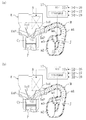
次に、図2を参照して、可変動弁装置Aを備えたエンジンEの吸気側動弁系の構成を詳細に説明する。この実施形態のエンジンEは、各気筒Cy(同図には示さず)毎に2つの吸気弁1,2(図1では符号InVを付したが、以下の動弁系の詳細説明では符号1,2を付す)と2つの排気弁ExV(図2には示さず)とを有する4弁式のダブルオーバヘッドカム方式を採用している。同図において、符号3は、前記4つの気筒Cy,Cy,…が並ぶエンジン前後方向(図の左右方向)に延びるように配設されていて、エンジンEのクランク軸によりカムチェーン(図示せず)を介して回転駆動される吸気側のカムシャフトである。
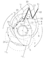
以下、そのようなリンクやカムの動作を、図5及び図6を参照して具体的に説明する。この両図では、コントロールアーム12、連結リンク8及び規制リンク13については簡略に直線で表しており、また、偏心カム6の中心(オフセットリンク7の外輪の中心)の回転軌跡を符号T0として示している。尚、上述の如く吸気弁1と揺動カム4との関係は吸気弁2と揺動カム5との関係と同じであって、揺動カム4は揺動カム5と同様に働くので、以下では、吸気弁2と揺動カム5との関係について説明する。
上述のようなリフト可変機構VVLの作動によって大リフト制御状態から小リフト制御状態まで連続的に変更される吸気弁1,2のリフトカーブを、図7に示す。同図においてリフトカーブL1は、揺動カム5が図5の実線位置(大リフト制御状態のリフトピーク近傍)と仮想線位置(ゼロリフト)との間で揺動する大リフト制御状態を示し、一方、L2は、揺動カム5が図6の実線位置(小リフト制御状態のリフトピーク近傍)と仮想線位置(ゼロリフト)との間で揺動する小リフト制御状態を示している。
ところで、上述の如くアイドル域では吸気弁1,2の位相角が大幅に遅角されて、それが気筒Cyの吸気上死点以降で開くようになるが、そうなると、該吸気弁1,2が開くまでのピストンPの下降によって気筒Cy内に負圧が生成されることから、その開弁に伴い吸気ポートInPのスロート部付近(独立吸気通路Jの弁側端)に生じる負圧波が低回転域としては非常に大きなものとなる。
Cy 気筒
E エンジン
J 独立吸気通路
m2 サージタンク(吸気集合部)
m3 連通路(容積室)
m4 シャッタ弁(開閉弁)
1,2 吸気弁
17 ECU
17a VIS制御部(開閉制御手段)
17d 加速検出手段
Claims (5)
- 少なくともエンジン負荷の増大に応じて吸気弁のリフト量を連続的に増大させるとともに、このリフト量の増大に伴って吸気弁の開弁期間が広がるようにその開弁時期及び閉弁時期の少なくとも一方を変更する可変動弁装置を備え、エンジンがアイドル運転域にあるときには気筒の吸気上死点以降で吸気弁を開くようにしたエンジンの吸気制御装置において、
吸気集合部から各気筒に至る独立吸気通路の途中には容積室に連通する連通口と、この連通口を開閉する開閉弁とが設けられ、その開閉弁により連通口が閉じられた状態では、前記独立吸気通路における吸気の圧力振動の同調回転数が所定回転数以下のエンジン低回転域に設定されており、
前記所定回転数よりも高回転側で前記連通口を開く一方、その所定回転数以下の前記エンジン低回転域では連通口を閉じるとともに、エンジンが前記アイドル運転域にあるときには前記低回転域であっても連通口を開くように、前記開閉弁を開閉制御する開閉弁制御手段を備え、
前記可変動弁装置は、エンジンが負荷の増大に応じて、前記アイドル運転域から高負荷側に隣接する部分負荷の運転域に移行すれば、吸気弁のリフト量を増大させるとともに、その開弁時期を吸気上死点側に進角させるものである
ことを特徴とするエンジンの吸気制御装置。 - 請求項1の吸気制御装置において、
前記可変動弁装置は、前記アイドル運転域からその高負荷側への移行後、さらにエンジンの負荷が増大すれば、吸気弁のリフト量を増大させるとともに、その開弁時期を吸気上死点付近に維持しつつ、閉弁時期を遅角させるものである
ことを特徴とするエンジンの吸気制御装置。 - 請求項1の吸気制御装置において、
前記可変動弁装置は、エンジンが前記アイドル運転域に対応する低回転状態のまま全負荷状態に移行したときには、吸気弁のリフト量を増大させるとともに、その閉弁時期を吸気下死点付近に遅角させるものであることを特徴とするエンジンの吸気制御装置。 - 請求項1〜3のいずれか1つの吸気制御装置において、
エンジンの加速運転状態を検出する加速検出手段を備え、
前記開閉弁制御手段は、エンジンが前記アイドル運転域にあって、且つ前記加速検出手段によりエンジンの加速運転状態が検出されれば、開閉弁により連通口を閉じるように構成されていることを特徴とするエンジンの吸気制御装置。 - 請求項1〜4のいずれか1つの吸気制御装置において、
前記容積室は、各気筒の独立吸気通路同士を連通するように設けられていることを特徴とするエンジンの吸気制御装置。
Priority Applications (4)
| Application Number | Priority Date | Filing Date | Title |
|---|---|---|---|
| JP2006037057A JP4696946B2 (ja) | 2006-02-14 | 2006-02-14 | エンジンの吸気制御装置 |
| EP07003062A EP1818523B1 (en) | 2006-02-14 | 2007-02-13 | Control of engine intake system |
| DE602007010196T DE602007010196D1 (de) | 2006-02-14 | 2007-02-13 | Steuerung eines Motoreinlasssystems |
| US11/674,170 US7444975B2 (en) | 2006-02-14 | 2007-02-13 | Control of engine intake system |
Applications Claiming Priority (1)
| Application Number | Priority Date | Filing Date | Title |
|---|---|---|---|
| JP2006037057A JP4696946B2 (ja) | 2006-02-14 | 2006-02-14 | エンジンの吸気制御装置 |
Publications (3)
| Publication Number | Publication Date |
|---|---|
| JP2007218114A JP2007218114A (ja) | 2007-08-30 |
| JP2007218114A5 JP2007218114A5 (ja) | 2009-03-26 |
| JP4696946B2 true JP4696946B2 (ja) | 2011-06-08 |
Family
ID=38122363
Family Applications (1)
| Application Number | Title | Priority Date | Filing Date |
|---|---|---|---|
| JP2006037057A Expired - Fee Related JP4696946B2 (ja) | 2006-02-14 | 2006-02-14 | エンジンの吸気制御装置 |
Country Status (4)
| Country | Link |
|---|---|
| US (1) | US7444975B2 (ja) |
| EP (1) | EP1818523B1 (ja) |
| JP (1) | JP4696946B2 (ja) |
| DE (1) | DE602007010196D1 (ja) |
Families Citing this family (8)
| Publication number | Priority date | Publication date | Assignee | Title |
|---|---|---|---|---|
| DE19830575A1 (de) * | 1998-07-08 | 2000-01-13 | Nonox B V | Ladungssteuervorrichtung für eine sowie Verfahren zum Steuern des Betriebs einer Hubkolbenbrennkraftmaschine |
| DE102006061438A1 (de) * | 2006-12-23 | 2008-06-26 | Dr.Ing.H.C. F. Porsche Ag | Verfahren und Steuergerät zur Überprüfung einer Saugrohrlängenverstellung bei einem Verbrennungsmotor |
| US7798126B2 (en) * | 2007-08-17 | 2010-09-21 | Gm Global Technology Operations, Inc. | Method for controlling cylinder charge in a homogeneous charge compression ignition engine |
| US7975672B2 (en) * | 2007-08-17 | 2011-07-12 | GM Global Technology Operations LLC | Method for controlling engine intake airflow |
| JP2010275888A (ja) * | 2009-05-27 | 2010-12-09 | Toyota Motor Corp | 車両用内燃機関の制御装置 |
| US8965628B2 (en) * | 2010-11-16 | 2015-02-24 | Ford Global Technologies, Llc | Powertrain thermal management system for a dry-clutch transmission |
| GB2519602B (en) * | 2013-10-28 | 2018-08-29 | Jaguar Land Rover Ltd | Method of Optimising Idling of an Internal Combustion Engine |
| DE102014205767A1 (de) * | 2014-03-27 | 2015-10-01 | Schaeffler Technologies AG & Co. KG | Verfahren zum Betrieb einer Brennkraftmaschine |
Citations (3)
| Publication number | Priority date | Publication date | Assignee | Title |
|---|---|---|---|---|
| JPH02115525A (ja) * | 1988-10-24 | 1990-04-27 | Mazda Motor Corp | エンジンの吸気装置 |
| JP2001336446A (ja) * | 2000-05-25 | 2001-12-07 | Nissan Motor Co Ltd | 内燃機関のノッキング制御装置 |
| JP2002266663A (ja) * | 2001-03-13 | 2002-09-18 | Nissan Motor Co Ltd | 内燃機関の吸気制御装置 |
Family Cites Families (22)
| Publication number | Priority date | Publication date | Assignee | Title |
|---|---|---|---|---|
| US4679531A (en) * | 1984-11-08 | 1987-07-14 | Mazda Motor Corporation | Intake system for internal combustion engine |
| JPS61116021A (ja) * | 1984-11-09 | 1986-06-03 | Mazda Motor Corp | エンジンの吸気装置 |
| US4738233A (en) * | 1985-02-25 | 1988-04-19 | Mazda Motor Corporation | Intake system for internal combustion engines |
| JPS61207822A (ja) * | 1985-03-12 | 1986-09-16 | Toyota Motor Corp | 吸気管長可変式吸気装置の吸気制御弁の制御方法 |
| JPS627922A (ja) * | 1985-07-01 | 1987-01-14 | Mazda Motor Corp | エンジンの吸気構造 |
| JPS6258016A (ja) * | 1985-09-06 | 1987-03-13 | Kanesaka Gijutsu Kenkyusho:Kk | エンジンの吸気装置 |
| JPS6263127A (ja) * | 1985-09-13 | 1987-03-19 | Mazda Motor Corp | エンジンの吸気装置 |
| JPS63111227A (ja) * | 1986-10-30 | 1988-05-16 | Mazda Motor Corp | エンジンの吸気装置 |
| US4846117A (en) * | 1987-04-21 | 1989-07-11 | Mazda Motor Corporation | Intake system for multiple-cylinder engine |
| GB2256674A (en) * | 1991-06-10 | 1992-12-16 | Ford Motor Co | Acoustic pipe coupling. |
| US5408962A (en) * | 1994-07-05 | 1995-04-25 | Ford Motor Company | Engine performance improvement |
| JP3250475B2 (ja) * | 1996-12-13 | 2002-01-28 | 三菱自動車工業株式会社 | 筒内噴射型内燃機関の制御装置 |
| DE19814970B4 (de) * | 1998-04-03 | 2006-03-02 | Dr.Ing.H.C. F. Porsche Ag | Sauganlage |
| DE19830575A1 (de) * | 1998-07-08 | 2000-01-13 | Nonox B V | Ladungssteuervorrichtung für eine sowie Verfahren zum Steuern des Betriebs einer Hubkolbenbrennkraftmaschine |
| DE19951083A1 (de) * | 1999-10-23 | 2001-04-26 | Mann & Hummel Filter | Luftansaugvorrichtung |
| JP4058927B2 (ja) * | 2001-09-18 | 2008-03-12 | 日産自動車株式会社 | 内燃機関の制御装置 |
| JP4385585B2 (ja) | 2002-10-18 | 2009-12-16 | トヨタ自動車株式会社 | 内燃機関 |
| JP2004197656A (ja) | 2002-12-18 | 2004-07-15 | Nissan Motor Co Ltd | 内燃機関の可変吸気装置 |
| JP4135546B2 (ja) | 2003-03-31 | 2008-08-20 | マツダ株式会社 | エンジンの可変動弁装置 |
| US7281512B2 (en) * | 2003-06-23 | 2007-10-16 | Siemens Vdo Automotive, Inc. | Passively variable plenum volume for a vehicle intake manifold assembly |
| EP1628002A3 (en) * | 2004-08-19 | 2009-09-09 | Mazda Motor Corporation | Intake system for multi-cylinder engine |
| JP4622431B2 (ja) | 2004-09-30 | 2011-02-02 | マツダ株式会社 | エンジンの可変動弁装置 |
-
2006
- 2006-02-14 JP JP2006037057A patent/JP4696946B2/ja not_active Expired - Fee Related
-
2007
- 2007-02-13 US US11/674,170 patent/US7444975B2/en not_active Expired - Fee Related
- 2007-02-13 DE DE602007010196T patent/DE602007010196D1/de active Active
- 2007-02-13 EP EP07003062A patent/EP1818523B1/en not_active Expired - Fee Related
Patent Citations (3)
| Publication number | Priority date | Publication date | Assignee | Title |
|---|---|---|---|---|
| JPH02115525A (ja) * | 1988-10-24 | 1990-04-27 | Mazda Motor Corp | エンジンの吸気装置 |
| JP2001336446A (ja) * | 2000-05-25 | 2001-12-07 | Nissan Motor Co Ltd | 内燃機関のノッキング制御装置 |
| JP2002266663A (ja) * | 2001-03-13 | 2002-09-18 | Nissan Motor Co Ltd | 内燃機関の吸気制御装置 |
Also Published As
| Publication number | Publication date |
|---|---|
| US7444975B2 (en) | 2008-11-04 |
| EP1818523A1 (en) | 2007-08-15 |
| JP2007218114A (ja) | 2007-08-30 |
| DE602007010196D1 (de) | 2010-12-16 |
| EP1818523B1 (en) | 2010-11-03 |
| US20070186892A1 (en) | 2007-08-16 |
Similar Documents
| Publication | Publication Date | Title |
|---|---|---|
| JP4696946B2 (ja) | エンジンの吸気制御装置 | |
| JP4682697B2 (ja) | エンジンの吸気制御装置 | |
| JP2007218114A5 (ja) | ||
| JP4506560B2 (ja) | エンジンの吸気制御装置 | |
| JP2003065089A (ja) | 内燃機関の可変動弁装置 | |
| JP2006274951A (ja) | 4サイクル火花点火式エンジン | |
| KR100815035B1 (ko) | 내연 기관의 밸브 작동 제어 장치 | |
| JP4506566B2 (ja) | エンジンの吸気制御装置 | |
| JP4765699B2 (ja) | レシプロ式内燃機関の制御方法 | |
| JP2010059945A (ja) | 内燃機関の可変動弁装置 | |
| JP4622431B2 (ja) | エンジンの可変動弁装置 | |
| JP2007056796A (ja) | 可変圧縮比機構を備えた内燃機関 | |
| JP4604358B2 (ja) | 内燃機関及びその制御システム | |
| JP4258453B2 (ja) | 内燃機関の吸気制御装置 | |
| JP4385585B2 (ja) | 内燃機関 | |
| JP4877209B2 (ja) | 内燃機関の制御装置 | |
| JPH0550574B2 (ja) | ||
| JP5034404B2 (ja) | 内燃機関の制御装置 | |
| JP5310207B2 (ja) | 内燃機関の動弁システム | |
| JP4432746B2 (ja) | 内燃機関の吸気制御装置 | |
| KR101136704B1 (ko) | 내연 기관의 가변 밸브 구동 장치 | |
| JP2003106176A (ja) | 内燃機関の吸気制御装置 | |
| JP2006097473A (ja) | エンジンの可変動弁装置 | |
| JP4063194B2 (ja) | 内燃機関のアイドル回転数制御装置 | |
| JP2005220754A (ja) | 可変圧縮比機構を備えた内燃機関 |
Legal Events
| Date | Code | Title | Description |
|---|---|---|---|
| A521 | Written amendment |
Free format text: JAPANESE INTERMEDIATE CODE: A523 Effective date: 20090210 |
|
| A621 | Written request for application examination |
Free format text: JAPANESE INTERMEDIATE CODE: A621 Effective date: 20090210 |
|
| A977 | Report on retrieval |
Free format text: JAPANESE INTERMEDIATE CODE: A971007 Effective date: 20100726 |
|
| A131 | Notification of reasons for refusal |
Free format text: JAPANESE INTERMEDIATE CODE: A131 Effective date: 20100803 |
|
| A521 | Written amendment |
Free format text: JAPANESE INTERMEDIATE CODE: A523 Effective date: 20100922 |
|
| A01 | Written decision to grant a patent or to grant a registration (utility model) |
Free format text: JAPANESE INTERMEDIATE CODE: A01 Effective date: 20110201 |
|
| A61 | First payment of annual fees (during grant procedure) |
Free format text: JAPANESE INTERMEDIATE CODE: A61 Effective date: 20110214 |
|
| LAPS | Cancellation because of no payment of annual fees |