JP4696946B2 - Engine intake control device - Google Patents
Engine intake control device Download PDFInfo
- Publication number
- JP4696946B2 JP4696946B2 JP2006037057A JP2006037057A JP4696946B2 JP 4696946 B2 JP4696946 B2 JP 4696946B2 JP 2006037057 A JP2006037057 A JP 2006037057A JP 2006037057 A JP2006037057 A JP 2006037057A JP 4696946 B2 JP4696946 B2 JP 4696946B2
- Authority
- JP
- Japan
- Prior art keywords
- intake
- valve
- engine
- lift
- lift amount
- Prior art date
- Legal status (The legal status is an assumption and is not a legal conclusion. Google has not performed a legal analysis and makes no representation as to the accuracy of the status listed.)
- Expired - Fee Related
Links
Images


Classifications
-
- F—MECHANICAL ENGINEERING; LIGHTING; HEATING; WEAPONS; BLASTING
- F02—COMBUSTION ENGINES; HOT-GAS OR COMBUSTION-PRODUCT ENGINE PLANTS
- F02D—CONTROLLING COMBUSTION ENGINES
- F02D41/00—Electrical control of supply of combustible mixture or its constituents
- F02D41/0002—Controlling intake air
-
- F—MECHANICAL ENGINEERING; LIGHTING; HEATING; WEAPONS; BLASTING
- F01—MACHINES OR ENGINES IN GENERAL; ENGINE PLANTS IN GENERAL; STEAM ENGINES
- F01L—CYCLICALLY OPERATING VALVES FOR MACHINES OR ENGINES
- F01L1/00—Valve-gear or valve arrangements, e.g. lift-valve gear
- F01L1/02—Valve drive
- F01L1/022—Chain drive
-
- F—MECHANICAL ENGINEERING; LIGHTING; HEATING; WEAPONS; BLASTING
- F01—MACHINES OR ENGINES IN GENERAL; ENGINE PLANTS IN GENERAL; STEAM ENGINES
- F01L—CYCLICALLY OPERATING VALVES FOR MACHINES OR ENGINES
- F01L13/00—Modifications of valve-gear to facilitate reversing, braking, starting, changing compression ratio, or other specific operations
- F01L13/0015—Modifications of valve-gear to facilitate reversing, braking, starting, changing compression ratio, or other specific operations for optimising engine performances by modifying valve lift according to various working parameters, e.g. rotational speed, load, torque
- F01L13/0021—Modifications of valve-gear to facilitate reversing, braking, starting, changing compression ratio, or other specific operations for optimising engine performances by modifying valve lift according to various working parameters, e.g. rotational speed, load, torque by modification of rocker arm ratio
- F01L13/0026—Modifications of valve-gear to facilitate reversing, braking, starting, changing compression ratio, or other specific operations for optimising engine performances by modifying valve lift according to various working parameters, e.g. rotational speed, load, torque by modification of rocker arm ratio by means of an eccentric
-
- F—MECHANICAL ENGINEERING; LIGHTING; HEATING; WEAPONS; BLASTING
- F02—COMBUSTION ENGINES; HOT-GAS OR COMBUSTION-PRODUCT ENGINE PLANTS
- F02B—INTERNAL-COMBUSTION PISTON ENGINES; COMBUSTION ENGINES IN GENERAL
- F02B27/00—Use of kinetic or wave energy of charge in induction systems, or of combustion residues in exhaust systems, for improving quantity of charge or for increasing removal of combustion residues
- F02B27/02—Use of kinetic or wave energy of charge in induction systems, or of combustion residues in exhaust systems, for improving quantity of charge or for increasing removal of combustion residues the systems having variable, i.e. adjustable, cross-sectional areas, chambers of variable volume, or like variable means
- F02B27/0205—Use of kinetic or wave energy of charge in induction systems, or of combustion residues in exhaust systems, for improving quantity of charge or for increasing removal of combustion residues the systems having variable, i.e. adjustable, cross-sectional areas, chambers of variable volume, or like variable means characterised by the charging effect
- F02B27/0215—Oscillating pipe charging, i.e. variable intake pipe length charging
-
- F—MECHANICAL ENGINEERING; LIGHTING; HEATING; WEAPONS; BLASTING
- F02—COMBUSTION ENGINES; HOT-GAS OR COMBUSTION-PRODUCT ENGINE PLANTS
- F02B—INTERNAL-COMBUSTION PISTON ENGINES; COMBUSTION ENGINES IN GENERAL
- F02B27/00—Use of kinetic or wave energy of charge in induction systems, or of combustion residues in exhaust systems, for improving quantity of charge or for increasing removal of combustion residues
- F02B27/02—Use of kinetic or wave energy of charge in induction systems, or of combustion residues in exhaust systems, for improving quantity of charge or for increasing removal of combustion residues the systems having variable, i.e. adjustable, cross-sectional areas, chambers of variable volume, or like variable means
- F02B27/0294—Actuators or controllers therefor; Diagnosis; Calibration
-
- F—MECHANICAL ENGINEERING; LIGHTING; HEATING; WEAPONS; BLASTING
- F02—COMBUSTION ENGINES; HOT-GAS OR COMBUSTION-PRODUCT ENGINE PLANTS
- F02D—CONTROLLING COMBUSTION ENGINES
- F02D13/00—Controlling the engine output power by varying inlet or exhaust valve operating characteristics, e.g. timing
- F02D13/02—Controlling the engine output power by varying inlet or exhaust valve operating characteristics, e.g. timing during engine operation
- F02D13/0223—Variable control of the intake valves only
- F02D13/0226—Variable control of the intake valves only changing valve lift or valve lift and timing
- F02D13/023—Variable control of the intake valves only changing valve lift or valve lift and timing the change of valve timing is caused by the change in valve lift, i.e. both valve lift and timing are functionally related
-
- F—MECHANICAL ENGINEERING; LIGHTING; HEATING; WEAPONS; BLASTING
- F01—MACHINES OR ENGINES IN GENERAL; ENGINE PLANTS IN GENERAL; STEAM ENGINES
- F01L—CYCLICALLY OPERATING VALVES FOR MACHINES OR ENGINES
- F01L1/00—Valve-gear or valve arrangements, e.g. lift-valve gear
- F01L1/12—Transmitting gear between valve drive and valve
- F01L1/14—Tappets; Push rods
- F01L1/143—Tappets; Push rods for use with overhead camshafts
-
- F—MECHANICAL ENGINEERING; LIGHTING; HEATING; WEAPONS; BLASTING
- F01—MACHINES OR ENGINES IN GENERAL; ENGINE PLANTS IN GENERAL; STEAM ENGINES
- F01L—CYCLICALLY OPERATING VALVES FOR MACHINES OR ENGINES
- F01L1/00—Valve-gear or valve arrangements, e.g. lift-valve gear
- F01L1/34—Valve-gear or valve arrangements, e.g. lift-valve gear characterised by the provision of means for changing the timing of the valves without changing the duration of opening and without affecting the magnitude of the valve lift
- F01L1/344—Valve-gear or valve arrangements, e.g. lift-valve gear characterised by the provision of means for changing the timing of the valves without changing the duration of opening and without affecting the magnitude of the valve lift changing the angular relationship between crankshaft and camshaft, e.g. using helicoidal gear
-
- F—MECHANICAL ENGINEERING; LIGHTING; HEATING; WEAPONS; BLASTING
- F01—MACHINES OR ENGINES IN GENERAL; ENGINE PLANTS IN GENERAL; STEAM ENGINES
- F01L—CYCLICALLY OPERATING VALVES FOR MACHINES OR ENGINES
- F01L1/00—Valve-gear or valve arrangements, e.g. lift-valve gear
- F01L1/02—Valve drive
- F01L1/04—Valve drive by means of cams, camshafts, cam discs, eccentrics or the like
- F01L1/047—Camshafts
- F01L1/053—Camshafts overhead type
- F01L2001/0537—Double overhead camshafts [DOHC]
-
- F—MECHANICAL ENGINEERING; LIGHTING; HEATING; WEAPONS; BLASTING
- F01—MACHINES OR ENGINES IN GENERAL; ENGINE PLANTS IN GENERAL; STEAM ENGINES
- F01L—CYCLICALLY OPERATING VALVES FOR MACHINES OR ENGINES
- F01L13/00—Modifications of valve-gear to facilitate reversing, braking, starting, changing compression ratio, or other specific operations
- F01L13/0015—Modifications of valve-gear to facilitate reversing, braking, starting, changing compression ratio, or other specific operations for optimising engine performances by modifying valve lift according to various working parameters, e.g. rotational speed, load, torque
- F01L13/0063—Modifications of valve-gear to facilitate reversing, braking, starting, changing compression ratio, or other specific operations for optimising engine performances by modifying valve lift according to various working parameters, e.g. rotational speed, load, torque by modification of cam contact point by displacing an intermediate lever or wedge-shaped intermediate element, e.g. Tourtelot
- F01L2013/0073—Modifications of valve-gear to facilitate reversing, braking, starting, changing compression ratio, or other specific operations for optimising engine performances by modifying valve lift according to various working parameters, e.g. rotational speed, load, torque by modification of cam contact point by displacing an intermediate lever or wedge-shaped intermediate element, e.g. Tourtelot with an oscillating cam acting on the valve of the "Delphi" type
-
- F—MECHANICAL ENGINEERING; LIGHTING; HEATING; WEAPONS; BLASTING
- F01—MACHINES OR ENGINES IN GENERAL; ENGINE PLANTS IN GENERAL; STEAM ENGINES
- F01L—CYCLICALLY OPERATING VALVES FOR MACHINES OR ENGINES
- F01L2800/00—Methods of operation using a variable valve timing mechanism
-
- F—MECHANICAL ENGINEERING; LIGHTING; HEATING; WEAPONS; BLASTING
- F01—MACHINES OR ENGINES IN GENERAL; ENGINE PLANTS IN GENERAL; STEAM ENGINES
- F01L—CYCLICALLY OPERATING VALVES FOR MACHINES OR ENGINES
- F01L2820/00—Details on specific features characterising valve gear arrangements
- F01L2820/03—Auxiliary actuators
- F01L2820/032—Electric motors
-
- F—MECHANICAL ENGINEERING; LIGHTING; HEATING; WEAPONS; BLASTING
- F02—COMBUSTION ENGINES; HOT-GAS OR COMBUSTION-PRODUCT ENGINE PLANTS
- F02B—INTERNAL-COMBUSTION PISTON ENGINES; COMBUSTION ENGINES IN GENERAL
- F02B27/00—Use of kinetic or wave energy of charge in induction systems, or of combustion residues in exhaust systems, for improving quantity of charge or for increasing removal of combustion residues
- F02B27/02—Use of kinetic or wave energy of charge in induction systems, or of combustion residues in exhaust systems, for improving quantity of charge or for increasing removal of combustion residues the systems having variable, i.e. adjustable, cross-sectional areas, chambers of variable volume, or like variable means
- F02B27/0226—Use of kinetic or wave energy of charge in induction systems, or of combustion residues in exhaust systems, for improving quantity of charge or for increasing removal of combustion residues the systems having variable, i.e. adjustable, cross-sectional areas, chambers of variable volume, or like variable means characterised by the means generating the charging effect
- F02B27/0247—Plenum chambers; Resonance chambers or resonance pipes
- F02B27/0263—Plenum chambers; Resonance chambers or resonance pipes the plenum chamber and at least one of the intake ducts having a common wall, and the intake ducts wrap partially around the plenum chamber, i.e. snail-type
-
- F—MECHANICAL ENGINEERING; LIGHTING; HEATING; WEAPONS; BLASTING
- F02—COMBUSTION ENGINES; HOT-GAS OR COMBUSTION-PRODUCT ENGINE PLANTS
- F02B—INTERNAL-COMBUSTION PISTON ENGINES; COMBUSTION ENGINES IN GENERAL
- F02B27/00—Use of kinetic or wave energy of charge in induction systems, or of combustion residues in exhaust systems, for improving quantity of charge or for increasing removal of combustion residues
- F02B27/02—Use of kinetic or wave energy of charge in induction systems, or of combustion residues in exhaust systems, for improving quantity of charge or for increasing removal of combustion residues the systems having variable, i.e. adjustable, cross-sectional areas, chambers of variable volume, or like variable means
- F02B27/0226—Use of kinetic or wave energy of charge in induction systems, or of combustion residues in exhaust systems, for improving quantity of charge or for increasing removal of combustion residues the systems having variable, i.e. adjustable, cross-sectional areas, chambers of variable volume, or like variable means characterised by the means generating the charging effect
- F02B27/0268—Valves
- F02B27/0273—Flap valves
-
- Y—GENERAL TAGGING OF NEW TECHNOLOGICAL DEVELOPMENTS; GENERAL TAGGING OF CROSS-SECTIONAL TECHNOLOGIES SPANNING OVER SEVERAL SECTIONS OF THE IPC; TECHNICAL SUBJECTS COVERED BY FORMER USPC CROSS-REFERENCE ART COLLECTIONS [XRACs] AND DIGESTS
- Y02—TECHNOLOGIES OR APPLICATIONS FOR MITIGATION OR ADAPTATION AGAINST CLIMATE CHANGE
- Y02T—CLIMATE CHANGE MITIGATION TECHNOLOGIES RELATED TO TRANSPORTATION
- Y02T10/00—Road transport of goods or passengers
- Y02T10/10—Internal combustion engine [ICE] based vehicles
- Y02T10/12—Improving ICE efficiencies
-
- Y—GENERAL TAGGING OF NEW TECHNOLOGICAL DEVELOPMENTS; GENERAL TAGGING OF CROSS-SECTIONAL TECHNOLOGIES SPANNING OVER SEVERAL SECTIONS OF THE IPC; TECHNICAL SUBJECTS COVERED BY FORMER USPC CROSS-REFERENCE ART COLLECTIONS [XRACs] AND DIGESTS
- Y02—TECHNOLOGIES OR APPLICATIONS FOR MITIGATION OR ADAPTATION AGAINST CLIMATE CHANGE
- Y02T—CLIMATE CHANGE MITIGATION TECHNOLOGIES RELATED TO TRANSPORTATION
- Y02T10/00—Road transport of goods or passengers
- Y02T10/10—Internal combustion engine [ICE] based vehicles
- Y02T10/40—Engine management systems
Description
本発明は、運転状態に応じて吸気弁のリフト量及び位相角を変化させる可変動弁装置を備えたエンジンの吸気制御装置に関し、特に、アイドル運転域における制御の技術分野に属する。 The present invention relates to an intake control device for an engine provided with a variable valve device that changes a lift amount and a phase angle of an intake valve according to an operating state, and particularly relates to a technical field of control in an idle operation region .
従来より、例えば特許文献1などに開示されるように、エンジンの動弁系に、吸気弁のリフト量や開閉時期を連続的に変化させるリフト可変機構を設けたものは知られている。このものでは、吸気側カムシャフトの偏心カムの動作をリンクを介して揺動カムに伝達し、この揺動カムによって吸気弁を開閉するようにしている。そして、前記リンクの支点の位置を変更することによって揺動カムの揺動軌跡を可変とし、これにより前記吸気弁のリフト量などを連続的に変化させるようにしている。 2. Description of the Related Art Conventionally, as disclosed in, for example, Japanese Patent Application Laid-Open No. H10-260260, there has been known an engine valve system that is provided with a variable lift mechanism that continuously changes the lift amount and opening / closing timing of an intake valve. In this device, the operation of the eccentric cam of the intake side camshaft is transmitted to the swing cam via a link, and the intake valve is opened and closed by this swing cam. Then, by changing the position of the fulcrum of the link, the swing locus of the swing cam is made variable so that the lift amount of the intake valve is continuously changed.
また、吸気カムの作動のクランク軸回転に対する位相を変化させることによって、吸気弁のリフトの位相角を所定の角度範囲内で連続的に変化させるようにした位相可変機構も周知である。そして、そのような位相可変機構を前記のようなリフト可変機構とともに備えて、吸気弁のリフト量及び位相角をエンジンの運転状態に応じて適切に変化させる可変動弁装置についても既に提案されている(例えば特許文献2などを参照)。 A phase variable mechanism is also known in which the phase angle of the intake valve lift is continuously changed within a predetermined angle range by changing the phase of the operation of the intake cam with respect to the crankshaft rotation. Further, a variable valve operating apparatus that includes such a phase variable mechanism together with the lift variable mechanism as described above and appropriately changes the lift amount and phase angle of the intake valve according to the operating state of the engine has already been proposed. (See, for example, Patent Document 2).
前記のような可変動弁装置を備えたエンジンではその運転状態に応じて、高負荷高回転側では吸気弁のリフト量や開弁期間を増大させ、さらに、吸気流の慣性を利用するために吸気弁の閉時期を気筒の吸気下死点以降まで大きく遅角させるのが好ましく、一方、低負荷側ではポンピングロスを削減するために所謂、吸気早閉じの特性とするのが好ましい。そのため、吸気弁のリフト特性としては、低負荷側ほどリフト量が小さくなり、且つ位相角が進角するように制御するのがよいと考えられる。 To increase the intake valve lift amount and valve opening period on the high-load high-rotation side of an engine equipped with the variable valve device as described above, and to use the inertia of the intake air flow It is preferable that the closing timing of the intake valve is greatly retarded until after the intake bottom dead center of the cylinder. On the other hand, on the low load side, a so-called early intake closing characteristic is preferable in order to reduce pumping loss. For this reason, it is considered that the lift characteristics of the intake valve should be controlled so that the lift amount becomes smaller and the phase angle is advanced as the load becomes lower.
但し、そのように低負荷側で位相角を進角させるようにした場合、アイドル運転時のようにエンジンの負荷が非常に低い運転状態では、吸気弁のリフト量が非常に小さくなる上に、それが実質的に気筒の吸気行程前半で閉じてしまい、リフトピーク時のピストンの下降速度も低いことから、気筒への吸気の充填量が著しく少なくなって、燃焼安定性が損なわれる虞れがある。 However, when the phase angle is advanced on the low load side, the lift amount of the intake valve becomes very small in an operating state where the engine load is very low, such as during idle operation. Since it closes substantially in the first half of the intake stroke of the cylinder and the lowering speed of the piston at the lift peak is also low, there is a possibility that the amount of intake charge to the cylinder will be remarkably reduced and combustion stability will be impaired. is there.
これに対し、本願の出願人は、吸気弁の基本的なリフト特性は前記のようなものとしながら、特にリフト量が小さくなるアイドル運転時などの特定の運転域においては、吸気弁のリフトの位相角を大幅に遅角させて、それが上死点以降に開き吸気効率の高い吸気行程の中期にリフトピーク状態となるように制御することで、燃焼安定性を確保するようにした可変動弁装置を開発して、先に特許出願している(特願2004−287164号を参照)。 On the other hand, the applicant of the present application assumes that the basic lift characteristics of the intake valve are as described above, but in a specific operation range such as idle operation where the lift amount is small, the intake valve lift Variable motion that ensures combustion stability by significantly retarding the phase angle and opening it after top dead center so that it reaches the lift peak state in the middle of the intake stroke with high intake efficiency A valve device has been developed and a patent application has been filed earlier (see Japanese Patent Application No. 2004-287164).
また、前記のような可変動弁装置とは別に、従来より例えば特許文献3に記載の如く、吸気の動的効果を利用して気筒への充填効率を高めることが行われており、エンジンの吸気系における吸気集合部から各気筒までの独立吸気通路の長さを長短、2段階に切り替えることで、その独立吸気通路における吸気の圧力振動の同調回転数をエンジン低回転域と高回転域とで切替えるようにした可変吸気システムも周知である。
しかしながら、前記先願に係る可変動弁装置を備えたエンジンに、前記周知の可変吸気システムも装備した場合は、上述の如くアイドル運転域で吸気弁のリフトの位相角を大幅に遅角させる結果として、吸気の気筒間ばらつきが大きくなり、燃焼安定性が低下するとともに、エンジンの振動や騒音が増大するという問題を生じる。 However, when the engine equipped with the variable valve device according to the prior application is also equipped with the known variable intake system, the result is that the phase angle of the lift of the intake valve is greatly retarded in the idle operation region as described above. As a result, there is a problem in that the variation in intake cylinders increases, combustion stability decreases, and engine vibration and noise increase.
すなわち、前記先願のもののようにアイドル運転域で位相角を大幅に遅角させて、吸気弁が気筒の吸気上死点以降で開くようにした場合、吸気弁が開くまでのピストンの下降によって気筒内に負圧が生成されることから、開弁後に独立吸気通路に生じる負圧波が低回転域としては非常に大きくなり、これにより励起される吸気の圧力振動がかなり大きくなる結果として、各気筒毎の吸気充填量のばらつきが増長されてしまうのである。 That is, considerably retard the phase angle in the idle operation range as those of the prior application, if the intake valve is to open the intake top dead center after the cylinder, lowering of the piston to open air intake valve Because negative pressure is generated in the cylinder by the negative pressure wave generated in the independent intake passage after opening the valve becomes very large as a low rotation range, and as a result, the pressure vibration of the intake air excited is considerably increased. The variation in the intake charge amount for each cylinder is increased.
この点、前記のような可変動弁装置では、カムシャフトの偏心部の動作を複数のリンクにより揺動カムに伝達し、これにより吸気弁を駆動するようにしており、吸気弁を駆動する部品の数が多いことから、本来、気筒間の吸気量ばらつきが大きくなり易いものであり、前記の不具合が特に大きくなる虞れがある。 In this respect, in the variable valve device as described above, the operation of the eccentric portion of the camshaft is transmitted to the swing cam by a plurality of links, thereby driving the intake valve, and the component that drives the intake valve Therefore, the variation in the intake air amount among the cylinders tends to be large, and the above-described problem may be particularly large.
本発明は、斯かる点に鑑みてなされたものであり、その目的とするところは、吸気弁のリフト量や位相角を調整する可変動弁装置を備えたエンジンにおいて、特にアイドル運転域で吸気弁のリフトの位相を大幅に遅角させるようにした場合に、吸気の圧力振動の増大によって気筒間の吸気量ばらつきが増長される、という新規な課題に着目し、これによる燃焼安定性の低下や振動騒音の増大を防止することにある。 The present invention has been made in view of the above points, and an object of the present invention is to provide an intake valve in an engine including a variable valve gear that adjusts a lift amount and a phase angle of an intake valve, particularly in an idle operation range . Focusing on the new problem that when the valve lift phase is greatly retarded, the variation in intake air volume between cylinders increases due to the increase in intake pressure oscillation, resulting in a decrease in combustion stability And to prevent an increase in vibration noise.
前記の目的を達成するために、本発明では、独立吸気通路の構造に工夫を凝らすことで、エンジンがアイドル運転域にあるときには、吸気弁のリフトの位相角を遅角させていても、これによる吸気の圧力振動の増大を抑制できるようにした。 In order to achieve the above-mentioned object, in the present invention, even if the phase angle of the lift of the intake valve is retarded when the engine is in the idle operation range , the structure of the independent intake passage is devised. It was made possible to suppress the increase in pressure vibration of intake air.
すなわち、請求項1の発明は、少なくともエンジン負荷の増大に応じて吸気弁のリフト量を連続的に増大させるとともに、このリフト量の増大に伴って吸気弁の開弁期間が広がるようにその開弁時期及び閉弁時期の少なくとも一方を変更する可変動弁装置を備え、エンジンがアイドル運転域にあるときには気筒の吸気上死点以降で吸気弁を開くようにしたエンジンの吸気制御装置を前提とする。 That is, according to the first aspect of the present invention, the lift amount of the intake valve is continuously increased at least according to an increase in the engine load, and the opening period of the intake valve is widened as the lift amount increases. Assuming an intake control device for an engine that has a variable valve system that changes at least one of the valve timing and the valve closing timing, and that opens the intake valve after the intake top dead center of the cylinder when the engine is in the idle operating range. To do.
そして、吸気集合部から各気筒に至る独立吸気通路の途中に容積室に連通する連通口と、この連通口を開閉する開閉弁とを設けて、その開閉弁により連通口を閉じた状態での当該独立吸気通路における吸気の圧力振動の同調回転数を、所定回転数以下のエンジン低回転域に設定し、さらに、前記所定回転数よりも高回転側で前記連通口を開く一方、所定回転数以下の前記エンジン低回転域では連通口を閉じるとともに、エンジンが前記アイドル運転域にあるときには前記低回転域であっても連通口を開くように、前記開閉弁を開閉制御する開閉弁制御手段を備え、
前記可変動弁装置は、エンジンが負荷の増大に応じて、前記アイドル運転域から高負荷側に隣接する部分負荷の運転域に移行すれば、吸気弁のリフト量を増大させるとともに、その開弁時期を吸気上死点側に進角させる構成とする。
A communication port that communicates with the volume chamber and an open / close valve that opens and closes the communication port are provided in the middle of the independent intake passage from the intake manifold to each cylinder, and the communication port is closed by the open / close valve. The synchronized rotational speed of the pressure vibration of the intake air in the independent intake passage is set to an engine low rotational speed range equal to or lower than a predetermined rotational speed, and the communication port is opened at a higher rotational speed than the predetermined rotational speed, while the predetermined rotational speed is On-off valve control means for opening and closing the on-off valve so as to close the communication port in the engine low-speed region and open the communication port even in the low-speed region when the engine is in the idle operation region. Prepared ,
The variable valve device increases the lift amount of the intake valve and opens the valve when the engine shifts from the idle operation region to the partial load operation region adjacent to the high load side as the load increases. The timing is advanced to the intake top dead center side .
前記の構成により、まず、エンジンの運転中に前記可変動弁装置によって、吸気弁のリフト量が少なくともエンジン負荷に応じて変更され、高負荷側ほどリフト量が大きくなり、低負荷側ほどリフト量が小さくされる。このことで、エンジンへの出力要求に対応する分量の空気を気筒へ充填することが可能になる。 According to the above configuration, first, the lift amount of the intake valve is changed according to at least the engine load by the variable valve device during operation of the engine, and the lift amount increases toward the high load side, and the lift amount decreases toward the low load side. Is reduced. This makes it possible to fill the cylinder with an amount of air corresponding to the output request to the engine.
また、アイドル運転域では、気筒の吸気上死点以降で吸気弁が開くようになり、吸気弁は吸気行程において特に吸気効率の高い期間に開くようになるから、リフト量は小さくても、所要の充填効率を確保して、燃焼安定性を高めることができる。 In the idle operation range , the intake valve opens after the intake top dead center of the cylinder, and the intake valve opens during the intake stroke, especially during periods of high intake efficiency. The charging efficiency can be ensured and the combustion stability can be improved.
一方、所定回転数以下のエンジン低回転域では、開閉弁制御手段による開閉弁の制御によって、独立吸気通路の途中に開口する容積室への連通口が閉じられ、当該独立吸気通路における吸気の圧力振動が気柱共鳴等により増幅されることで、つまり、所謂動的効果によって、気筒への吸気充填効率が高められる。 On the other hand, in a low engine speed range of a predetermined number of revolutions or less, the on / off valve control by the on / off valve control means closes the communication port to the volume chamber that opens in the middle of the independent intake passage, and the intake pressure in the independent intake passage The vibration is amplified by air column resonance or the like, that is, the so-called dynamic effect increases the intake charge efficiency into the cylinder.
この際、前記低回転域に含まれるアイドル運転域では、吸気弁を吸気上死点以降で開くようにしているので、その開弁に伴い独立吸気通路の弁側端に生じる負圧波が低回転域としては非常に大きくなり、これにより励起される圧力振動がかなり大きくなる結果として、各気筒毎の吸気充填量のばらつきが増長される虞れがある。 At this time, in the idle operation region included in the low rotation region, the intake valve is opened after the intake top dead center, so that the negative pressure wave generated at the valve side end of the independent intake passage due to the valve opening is low rotation. As a result, the pressure vibration excited by this region becomes very large, and as a result, the variation in intake charge amount for each cylinder may be increased.
しかしながら、前記の構成では、エンジンが前記アイドル運転域にあるときには、前記低回転域であっても開閉弁制御手段により開閉弁を開くようにしており、これにより独立吸気通路の途中が容積室に連通されることで、圧力振動の増幅作用が低下することから、起振源となる負圧波が大きくなっていても、気筒間の吸気のばらつきが増長されることはなくなり、エンジンの燃焼安定性の低下や振動騒音の増大を防止することができる。 However, in the above configuration, when the engine is in the idle operation range , the on / off valve is opened by the on / off valve control means even in the low rotation range, so that the middle of the independent intake passage is in the volume chamber. By communicating, the amplification effect of pressure vibration is reduced, so even if the negative pressure wave that is the source of vibration is large, the variation in intake air between cylinders will not be increased, and engine combustion stability Can be prevented, and vibration noise can be prevented from increasing.
また、前記可変動弁装置は、エンジンが負荷の増大に応じて、アイドル運転域から高負荷側に隣接する部分負荷の運転域に移行する際、吸気弁のリフト量を増大させるとともに、その開弁時期を吸気上死点側に進角させるから、エンジンの部分負荷域において所謂吸気早閉じによりポンピングロスを削減し、燃費を低減することができる。 Further, the variable valve device increases the lift amount of the intake valve and opens the engine when the engine shifts from the idle operation region to the partial load operation region adjacent to the high load side as the load increases. Since the valve timing is advanced toward the intake top dead center, pumping loss can be reduced by so-called early intake closing in the partial load region of the engine, and fuel consumption can be reduced.
好ましいのは、前記容積室を、各気筒の独立吸気通路同士を連通するように設けることであり(請求項5の発明)、こうすれば、連通口が開かれたときには、吸気圧振動の気筒間干渉によって各独立吸気通路における吸気の圧力振動をより効果的に低減することができる。 Preferably, the volume chamber is provided so that the independent intake passages of the respective cylinders communicate with each other (invention of claim 5 ), and in this way, when the communication port is opened, the cylinder of intake pressure oscillation is provided. The pressure vibration of the intake air in each independent intake passage can be more effectively reduced by the interference.
また、好ましいのは、エンジンの加速運転状態を検出する加速検出手段を備え、前記開閉弁制御手段を、エンジンがアイドル運転域にあっても、前記加速検出手段によりエンジンの加速運転状態が検出されれば、開閉弁により連通口を閉じるように構成することである(請求項4の発明)。こうすれば、加速運転時には独立吸気通路における吸気の圧力振動を十分に増幅し、気筒への吸気充填効率を高めて、エンジンの加速性能を向上することができる。 Preferably, an acceleration detection means for detecting an acceleration operation state of the engine is provided, and the on-off valve control means detects the acceleration operation state of the engine by the acceleration detection means even when the engine is in an idle operation region. In this case, the communication port is closed by the open / close valve (invention of claim 4 ). By so doing, it is possible to sufficiently amplify the pressure vibration of the intake air in the independent intake passage during acceleration operation, increase the intake air charging efficiency into the cylinder, and improve the acceleration performance of the engine.
そして、さらにエンジン負荷が増大すれば、吸気弁のリフト量を増大させるとともに、その開弁時期を吸気上死点付近に維持しつつ、閉弁時期は遅角させるのが好ましい(請求項2の発明)。こうすれば、ポンピングロスを削減しつつ、エンジンへの出力要求に対応する吸気充填効率が得られる。 Then, if increased further engine load, together with increasing the lift amount of the intake valve while maintaining the opening timing in the vicinity of the intake top dead center, preferably to retard the closing timing (according to claim 2 invention). In this way, it is possible to obtain the intake charging efficiency corresponding to the output demand to the engine while reducing the pumping loss.
一方、エンジンがアイドル運転域に対応する低回転状態のまま全負荷状態に移行したときには、吸気弁のリフト量を増大させるとともに、その閉弁時期を吸気下死点付近に遅角させるのが好ましい(請求項3の発明)。こうすれば、気筒からの吸気の吹き返しがなくなり、吸気充填効率を最大限に高めることができる。 On the other hand, when the engine shifts to the full load state in the low rotation state corresponding to the idle operation region , it is preferable to increase the lift amount of the intake valve and retard the valve closing timing near the intake bottom dead center. (Invention of Claim 3 ). In this way, the intake air from the cylinder is not blown back, and the intake charge efficiency can be maximized.
以上、説明したように、前記請求項1の発明に係るエンジンの吸気制御装置によると、吸気弁のリフト量及び位相角の制御によってエンジンへの出力要求に対応する吸気充填量が得られるとともに、アイドル運転域では、吸気弁を吸気行程において特に吸気効率の高い期間に開かせることで、リフト量は小さくても所要の充填効率を確保して、燃焼安定性を高めることができる。 As described above, according to the intake control apparatus for an engine according to the first aspect of the invention, the intake charge amount corresponding to the output request to the engine can be obtained by controlling the lift amount and the phase angle of the intake valve, and In the idling operation region , by opening the intake valve during a period of particularly high intake efficiency in the intake stroke, the required charging efficiency can be ensured and the combustion stability can be improved even if the lift amount is small.
また、エンジン低回転域では所謂動的効果によって気筒への吸気充填効率を高めることができるとともに、特に前記アイドル運転域においては独立吸気通路の途中を容積室に連通して、吸気の圧力振動の増幅作用を低下させることで、吸気の気筒間ばらつきが増長されることを回避し、燃焼安定性の低下や振動騒音の増大を防止することができる。 In addition, the so-called dynamic effect can improve the efficiency of intake charging into the cylinder in the low engine speed range, and in particular, in the idle operation range , the middle of the independent intake passage communicates with the volume chamber to reduce the pressure vibration of the intake air. By reducing the amplifying action, it is possible to avoid an increase in the variation between the cylinders of the intake air, and to prevent a decrease in combustion stability and an increase in vibration noise.
さらに、アイドル運転域の高負荷側に隣接する部分負荷の運転域においては、吸気弁を所謂早閉じの特性とすることで、ポンピングロスを削減し、エンジンの燃費を低減することができる。 Further, in the partial load operation region adjacent to the high load side of the idle operation region , the pumping loss can be reduced and the fuel consumption of the engine can be reduced by making the intake valve have a so-called early closing characteristic.
また、前記アイドル運転域からその高負荷側への移行後、さらにエンジン負荷が増大すれば、請求項2の発明のように、吸気弁のリフト量を増大させるとともに、その開弁時期を吸気上死点付近に維持しつつ、閉弁時期は遅角させることで、ポンピングロスを削減しつつ、エンジンへの出力要求に対応する吸気充填効率が得られる。 Further, if the engine load further increases after the transition from the idle operation range to the high load side, the lift amount of the intake valve is increased and the valve opening timing is increased as shown in the invention of
一方、低回転の全負荷状態では、請求項3の発明のように吸気弁を下死点付近で閉じることにより、全負荷に対応して吸気充填効率を最大限に高めることができる。 On the other hand, in the low load full load state, the intake valve efficiency is maximized corresponding to the full load by closing the intake valve near the bottom dead center as in the third aspect of the invention.
さらにまた、請求項4の発明のように、エンジンの加速運転時にはそれがアイドル運転域にあっても、独立吸気通路を容積室から遮断することで、気筒への吸気充填効率を高めて、エンジンの加速性能を向上できる。 Further, as in the fourth aspect of the invention, even when the engine is accelerating, even if the engine is in the idling operation region , the independent intake passage is cut off from the volume chamber, so that the efficiency of intake charging into the cylinder can be improved. Acceleration performance can be improved.
また、請求項5の発明のように、前記容積室を各気筒の独立吸気通路同士を連通するように設ければ、連通口の開放時に各独立吸気通路における吸気の圧力振動をより効果的に低減できる。
Further, if the volume chamber is provided so that the independent intake passages of the respective cylinders communicate with each other as in the invention of
以下、本発明の実施形態を図面に基づいて詳細に説明する。尚、以下の好ましい実施形態の説明は、本質的に例示に過ぎず、本発明、その適用物或いはその用途を制限することを意図するものではない。 Hereinafter, embodiments of the present invention will be described in detail with reference to the drawings. It should be noted that the following description of the preferred embodiment is merely illustrative in nature, and is not intended to limit the present invention, its application, or its use.
(吸気系の全体構成)
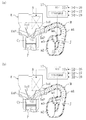
図1は、本発明の実施形態に係るエンジンEの吸気系の構成を模式的に示す。この実施形態のエンジンEは、一例として4つの気筒Cy,Cy,…(図には1つのみ示す)が一列に並んだ直列4気筒エンジンであり、図示の如く、各気筒Cy内にはピストンPが往復動可能に嵌挿されている。また、各気筒Cy内に臨んでそれぞれ開口するように吸気ポートInP及び排気ポートExPが形成され、その各ポート開口部には各々、吸気弁InV及び排気弁ExVが配設されている。吸気弁InVを駆動する吸気側の動弁系には、後に詳述するように、吸気弁InVのリフト量及び位相角を可変とする可変動弁装置Aが配設されている。
(Whole structure of intake system)
FIG. 1 schematically shows the configuration of an intake system of an engine E according to an embodiment of the present invention. The engine E of this embodiment is an in-line four-cylinder engine in which four cylinders Cy, Cy,... (Only one is shown in the figure) are arranged in a row as an example. P is inserted so as to be able to reciprocate. Further, an intake port InP and an exhaust port ExP are formed so as to open in the respective cylinders Cy, and an intake valve InV and an exhaust valve ExV are provided in the respective port openings. As will be described later in detail, a variable valve gear A that makes the lift amount and phase angle of the intake valve InV variable is disposed in the valve system on the intake side that drives the intake valve InV.
また、前記エンジンEの吸気側(図の右側)に配置接続された吸気マニホルドMには、内部の通路が各気筒Cy毎の吸気ポートInPに連通する4つの分岐管m1,m1,…(図には1つのみ示す)と、吸気集合部であるサージタンクm2とが設けられている。そして、図示しないエアクリーナ等を介してサージタンクm2に供給された空気は、分岐管m1内の通路と吸気ポートInPとを介して各気筒Cyに個別に供給されるようになっており、こうして、サージタンクm2から各気筒Cyに至る独立吸気通路Jが形成されている。 Further, the intake manifold M arranged and connected to the intake side (right side of the figure) of the engine E has four branch pipes m1, m1,... (In which the internal passage communicates with the intake port InP for each cylinder Cy). And only one is shown), and a surge tank m2 which is an intake air collecting portion. The air supplied to the surge tank m2 via an air cleaner or the like (not shown) is supplied individually to each cylinder Cy via the passage in the branch pipe m1 and the intake port InP. An independent intake passage J extending from the surge tank m2 to each cylinder Cy is formed.
さらに、この実施形態では、前記4つの分岐管m1,m1,…同士を途中で連通するように連通管m3(容積室)が設けられており、この連通管m3が各分岐管m1内の通路に臨んで開口する各開口部(容積室に連通する連通口)には、それぞれ、該各開口部を開閉するようにシャッタ弁m4(開閉弁)が配設されている。このシャッタ弁m4は、図示しない電動モータによって開閉作動されるもので、これにより連通管m3の開口部が閉じられた状態では、前記独立吸気通路Jにおける吸気の圧力振動が、所定回転数(例えば3500から4000rpm)以下のエンジン低回転域において同調するようになっている。 Further, in this embodiment, a communication pipe m3 (volume chamber) is provided so as to communicate the four branch pipes m1, m1,... Halfway, and this communication pipe m3 is a passage in each branch pipe m1. A shutter valve m4 (open / close valve) is disposed at each opening (communication port communicating with the volume chamber) that opens to face the opening so as to open and close each opening. The shutter valve m4 is opened and closed by an electric motor (not shown). With this, when the opening of the communication pipe m3 is closed, the pressure vibration of the intake air in the independent intake passage J becomes a predetermined rotational speed (for example, The engine is tuned in the low engine speed range of 3500 to 4000 rpm) or less.
すなわち、同図(a)に示すように、シャッタ弁m4により連通管m3の開口部が閉じられた状態では、吸気弁InVの開弁に伴い独立吸気通路Jの弁側端、即ち、吸気ポートInPのスロート部付近に生じる負圧波が、独立吸気通路Jを吸気上流側に伝播し、その上流端であるサージタンクm2の容積部開放端で逆位相反転して、正圧波となる。そして、この正圧波が独立吸気通路Jを吸気下流側に伝播し、同調回転数であれば、吸気弁InVが閉じる直前にその近傍に到達して、吸気充填効率を高めるようになる(吸気慣性効果)。 That is, as shown in FIG. 5A, in the state where the opening of the communication pipe m3 is closed by the shutter valve m4, the valve side end of the independent intake passage J, that is, the intake port is accompanied by the opening of the intake valve InV. A negative pressure wave generated in the vicinity of the throat portion of InP propagates through the independent intake passage J to the intake upstream side, and reverses the phase at the open end of the volume portion of the surge tank m2, which is the upstream end thereof, to become a positive pressure wave. Then, if this positive pressure wave propagates through the independent intake passage J to the downstream side of the intake air and is at the synchronized rotational speed, it reaches the vicinity immediately before the intake valve InV is closed, and the intake charge efficiency is increased (intake inertia). effect).
また、そのような圧力波による吸気の圧力振動は次のサイクルの吸気行程まで独立吸気通路J内に残存し、吸気弁InVが開くときに再び正圧波が到達すれば、吸気の気筒Cy内への流入を加速し、吸気充填効率を高めるようになる(脈動効果)。 Further, the pressure vibration of the intake air due to such a pressure wave remains in the independent intake passage J until the intake stroke of the next cycle, and if a positive pressure wave arrives again when the intake valve InV is opened, it will enter the intake cylinder Cy. Accelerates the inflow of air and increases the intake charge efficiency (pulsation effect).
一方、同図(b)に示すように連通管m3の開口部が開かれた状態では、前記のように吸気弁InVの開弁に伴い発生する負圧波が連通管m3の開口部にて逆位相反転することになるので、ここから吸気弁InVのところまで正圧波が戻ってくる時間が短くなり、同調回転数はエンジン高回転域に現れることになる。 On the other hand, in the state where the opening of the communication pipe m3 is opened as shown in FIG. 5B, the negative pressure wave generated when the intake valve InV is opened as described above is reversed at the opening of the communication pipe m3. Since the phase is inverted, the time for the positive pressure wave to return from here to the intake valve InV is shortened, and the synchronized rotational speed appears in the high engine speed range.
つまり、この実施形態のエンジンEの吸気系には、独立吸気通路Jにおける吸気の圧力振動が同調するエンジン回転数(同調回転数)をエンジン低回転域と高回転域とで切替えることにより、低回転から高回転まで吸気の動的効果を有効利用して、気筒Cyへの充填効率を高める可変吸気システム(Variable Induction System、以下、VISと呼ぶ)が装備されている。 That is, the intake system of the engine E of this embodiment has a low engine speed by switching the engine speed (synchronized speed) at which the pressure vibration of the intake air in the independent intake passage J is synchronized between the low engine speed range and the high engine speed range. It is equipped with a variable intake system (hereinafter referred to as VIS) that increases the charging efficiency of the cylinder Cy by effectively utilizing the dynamic effect of intake air from rotation to high rotation.
前記シャッタ弁m4の作動制御は、以下に述べる可変動弁装置Aの作動制御とともに、エンジンコントロールユニット17(以下、ECUと呼ぶ)によって行われる。このECU17は、少なくともエンジン回転数センサ26(クランク角センサでよい)や吸気流量センサ27等、エンジンEの運転状態を検出するための各種センサからの信号を入力するとともに、車両のアクセルペダルの踏み操作量(アクセル開度)を検出するアクセル開度センサ28からの信号を入力し、所定の制御プログラムを実行することによって、前記シャッタ弁m4を開閉制御するようになっている。
The operation control of the shutter valve m4 is performed by the engine control unit 17 (hereinafter referred to as ECU) together with the operation control of the variable valve operating apparatus A described below. The
すなわち、この実施形態ではECU17は、主にエンジン回転数に応じて、所定回転数以下のエンジン低回転域ではシャッタ弁m4により連通管m3の開口部を閉じる一方、所定回転数よりも高回転側では該開口部を開くように、当該シャッタ弁m4を開閉制御するVIS制御部17a(開閉制御手段)をプログラムの形態で備えている。尚、詳しくは後述するが、VIS弁制御部17aは、エンジンEがアイドル域(アイドル運転域)にあるときには、低回転域であっても連通管m3の開口部を開くようになっている。
That is, in this embodiment, the
(可変動弁装置の構成)
次に、図2を参照して、可変動弁装置Aを備えたエンジンEの吸気側動弁系の構成を詳細に説明する。この実施形態のエンジンEは、各気筒Cy(同図には示さず)毎に2つの吸気弁1,2(図1では符号InVを付したが、以下の動弁系の詳細説明では符号1,2を付す)と2つの排気弁ExV(図2には示さず)とを有する4弁式のダブルオーバヘッドカム方式を採用している。同図において、符号3は、前記4つの気筒Cy,Cy,…が並ぶエンジン前後方向(図の左右方向)に延びるように配設されていて、エンジンEのクランク軸によりカムチェーン(図示せず)を介して回転駆動される吸気側のカムシャフトである。
(Configuration of variable valve operating device)
Next, the configuration of the intake side valve system of the engine E provided with the variable valve apparatus A will be described in detail with reference to FIG. The engine E of this embodiment has two
前記カムシャフト3の前端部には、該カムシャフト3のクランク軸に対する回転位相を所定の角度範囲内で変更可能な公知の位相可変機構18(Variable Cam Timing:以下、VCTと略称する)が付設されている。詳しい説明は省略するが、このVCT18は、スプロケット19の中心孔を貫通するカムシャフト3の前端に固定されたロータと、このロータをエンジン前方から覆うように配置されてスプロケット19に固定されたケーシングとからなり、このロータ及びケーシングの間には周方向に並んで複数の油圧作動室が形成されている。
A known phase variable mechanism 18 (Variable Cam Timing: hereinafter abbreviated as VCT) capable of changing the rotational phase of the
そして、ECU17からの制御信号の入力に応じて、電磁弁20の位置が切換えられることにより、前記VCT18の油圧作動室に供給される作動油圧の方向が切換えられて、前記ロータ及びケーシング、即ちカムシャフト3とスプロケット19とが相対的に回動されるようになっている。前記電磁弁20は、作動油圧の大きさを連続的に変更可能なデューティソレノイドバルブなどであり、これによりロータのケーシングに対する回動量を所定範囲内で連続的に変化させることで、カムシャフト3のクランク軸に対する回転の位相を連続的に変更して、クランク角で見た吸気弁1,2の開閉時期、即ち吸気弁1,2のリフトの位相角を連続的に変更することができる。
Then, in response to the input of a control signal from the
また、前記カムシャフト3には、各気筒Cy毎に一対の揺動カム4,5が揺動自在に支持されている。これら一対の揺動カム4,5は、前記2つの吸気弁1,2にそれぞれ対応するように配置され、円筒状の連結部9によって互いに連結されて、カムシャフト3の周りに一体に揺動するようになっている。これにより、各気筒Cy毎2つの吸気弁1,2が同時にリフトされる。尚、前記連結部9の外周面は、カム軸受面と摺接するカムジャーナル部とされている。
A pair of rocking
前記の如く揺動カム4,5を動作させるために、前記カムシャフト3には、その軸心X(カムシャフト3の回転中心:図3等参照)から偏心した4つの円形の偏心カム6が互いに間隔を空けて一体に設けられている。この各偏心カム6にはそれぞれ回転自在に外輪7が外嵌めされていて、この外輪7の外周に突出するように設けられた偏心凸部に、連結リンク8を介して前記揺動カム5が連結されている。すなわち、前記外輪7は、一端側が前記カムシャフト3の偏心カム6に回転自在に嵌合され、他端部(偏心凸部)が連結リンク8によって揺動カム5に連結されたリンク(以下、オフセットリンクという)である。
In order to operate the
また、前記カムシャフト3の斜め上方には、これと平行にコントロールシャフト11が設けられている。このコントロールシャフト11には4つのコントロールアーム12がそれぞれ結合固定されており、該各コントロールアーム12の先端部と前記オフセットリンク7の他端部とが規制リンク13によって連結されている。この規制リンク13は、前記偏心カム6の回転に伴いオフセットリンク7の一端側がカムシャフト3の周りを公転するときに、このオフセットリンク7の変位を規制してその他端部を往復運動させるものであり、これにより、そのオフセットリンク7の他端部に連結された前記連結リンク8が揺動カム4,5を揺動させることになる。
A
さらに、前記コントロールシャフト11には、円周の一部のみに歯が形成されたウォーム歯車14が結合され、このウォーム歯車14の歯に、電動モータ15で回転駆動されるウォーム16が噛み合っている。そうして、ECU17からの制御信号の入力に応じてモータ15が作動し、コントロールシャフト11が回動してコントロールアーム12の位置が変わることによって、オフセットリンク7の他端部の往復運動の軌跡、即ち前記連結リンク8の揺動軌跡が変更され、これにより揺動カム4,5の揺動角などが変化して、吸気弁1,2のリフト量や開閉時期などのリフト特性が変化するようになっている。
Further, the
言い換えると、前記連結リンク8及び規制リンク13は、揺動カム5とオフセットリンク7とを連結するとともに、前記偏心カム6の回転に伴う該オフセットリンク7の動作を、揺動カム5(及び揺動カム4)が揺動するように規制するリンク機構を構成している。また、そのリンク機構を含めて、前記カムシャフト3の偏心カム6、オフセットリンク7、コントロールシャフト11、コントロールアーム12等により、吸気弁1,2のリフト量を連続的に変更可能なリフト可変機構(Variable Valve Lift:以下、VVLともいう)が構成されている。
In other words, the connecting
そのVVLの構成についてより具体的には、まず、図3(b)に示すように、吸気弁2のステム上端には直動式タペット21が設けられ、このタペット21に揺動カム5が当接している。吸気弁2は、タペット21内部に設けられたリテーナ22とシリンダヘッドに設けられたリテーナ23との間に配設されたバルブスプリング24によって、吸気ポートInPを閉じる方向(吸気弁1,2リフト方向とは反対方向)に付勢されている。尚、吸気弁1についても前記吸気弁2と同様の構成になっている。
More specifically, the configuration of the VVL is as follows. First, as shown in FIG. 3 (b), a
前記連結リンク8の一端部は、揺動カム5にピン31により回動自在に連結され、一方、規制リンク13の一端部は、コントロールアーム12の先端部にピン32により回動自在に連結されている。そうして、この連結リンク8と規制リンク13とは、オフセットリンク7の両側にそれぞれ配設されて、該オフセットリンク7を中間に挟んで連係している。すなわち、連結リンク8及び規制リンク13の各々の他端部は、オフセットリンク7の他端部に連結ピン33によって同軸に且つ回動自在に連結されている。尚、前記ピン31〜33はいずれもカムシャフト3と平行に延びている。
One end portion of the
図示の如く、前記オフセットリンク7と連結リンク8との連結ピン33はカムシャフト3の上方に位置しており、その側方にはコントロールアーム12の回動中心(コントロールシャフト11の軸心)が位置している。コントロールアーム12の先端のピン32は規制リンク13の回動軸であり、そのピン32の位置を変更することによって規制リンク13及び連結ピン33の揺動軌跡を変化させ、これにより、吸気弁1,2のリフト量を変更することができる。
As shown in the figure, the connecting
すなわち、各リンクやピンの具体的な動作については以下に詳述するが、モータ15によりコントロールシャフト11及びコントロールアーム12を回動させて、図3に示すようにピン32をコントロールシャフト11の下方に位置づけると、揺動カム4,5の揺動角が大きくなり、リフトピークにおける吸気弁1,2のリフト量が最も大きな大リフト制御状態になる。また、そこからコントロールアーム12などの回動によってピン32を上方へ移動させると、これに応じて揺動カム4,5の揺動角は小さくなり、図4に示すようにピン32をカムシャフト3の上方に位置付けると、吸気弁1,2のリフト量が最も小さな小リフト制御状態になる。
That is, the specific operation of each link and pin will be described in detail below, but the
前記図3に示す大リフト制御状態において、揺動カム5は、同図(b)に示すようにカムノーズの先端側で直動式タペット21を押圧し、該タペット21を介して吸気弁2を大きくリフトさせたリフトピークの状態(揺動カム4が直動式タペットを介して吸気弁1を大きくリフトさせた状態)と、同図(a)に示すように吸気弁2(吸気弁1)がリフトしないゼロリフトの状態との間で揺動する。小リフト制御状態である図4の場合も同様にリフトピークの状態(カムノーズの基端側でタペット21を押圧)とゼロリフトの状態との間で揺動する(同図(a)及び(b)参照)。
In the large lift control state shown in FIG. 3, the
(リフト可変機構の動作)
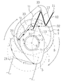
以下、そのようなリンクやカムの動作を、図5及び図6を参照して具体的に説明する。この両図では、コントロールアーム12、連結リンク8及び規制リンク13については簡略に直線で表しており、また、偏心カム6の中心(オフセットリンク7の外輪の中心)の回転軌跡を符号T0として示している。尚、上述の如く吸気弁1と揺動カム4との関係は吸気弁2と揺動カム5との関係と同じであって、揺動カム4は揺動カム5と同様に働くので、以下では、吸気弁2と揺動カム5との関係について説明する。
(Operation of variable lift mechanism)
Hereinafter, the operation of such links and cams will be described in detail with reference to FIGS. In both figures, the
まず、図5を参照して揺動カム5自体のプロファイルを説明すると、この揺動カム5の周面には、曲率半径が所定角度範囲一定の基円面(ベースサークル区間)θ1と、該θ1に続いて曲率半径が漸次大きくなっているカム面(リフト区間)θ2とが形成されている。同図は、前記図3の大リフト制御状態を表しており、コントロールアーム12は大リフト制御位置にある。
First, the profile of the
同図に実線で示すのは吸気弁2がリフトピーク近傍にある図3(b)の状態であり、このときには、連結リンク8によってピン31が最も上方に引き上げられ、揺動カム5は、カム面θ2のカムノーズ先端側がタペット21に当接した状態になっている。一方、仮想線で示すのはゼロリフトの状態(図3(a))であり、このときには揺動カム5の基円面θ1がタペット21に接していて、吸気弁2はリフトしていない(吸気弁2は閉じている)。
The solid line in FIG. 3 shows the state of FIG. 3B in which the
そして、カムシャフト3(偏心カム6)が図の時計回りに回転すると、これに伴いオフセットリンク7の一端側(図の下端側)は、図に矢印で示すようにカムシャフト3の軸心X周りを公転することになるが、このときにはオフセットリンク7の他端部の変位は、そこに連結されている規制リンク13によって規制される。すなわち、規制リンク13は、コントロールシャフト11の下方に位置付けられたピン32を中心に図の実線の位置と仮想線の位置との間を揺動し、これに伴い、オフセットリンク7の他端側(連結ピン33)は、偏心カム6が1回転する度に、ピン32を中心として往復円弧運動をすることになる(この連結ピン33の運動軌跡をT1として示す)。
When the camshaft 3 (eccentric cam 6) rotates in the clockwise direction in the figure, one end side (lower end side in the figure) of the offset
前記連結ピン33の往復円弧運動T1に伴い、この同じ連結ピン33によって一端部がオフセットリンク7に連結されている連結リンク8の他端部(ピン31)は、図にT2として示す軌跡で往復円弧運動し、そのピン31によって連結リンク8に連結されている揺動カム5が図の実線の位置と仮想線の位置との間で揺動運動をする。すなわち、前記連結ピン33が上方に移動するときには、連結リンク8によってピン31が上方に引き上げられて、揺動カム5のカムノーズがタペット21を押し下げ、これによりバルブスプリング24(図3参照)を押し縮めながら、吸気弁2をリフトさせる。
With the reciprocating arc motion T1 of the connecting
一方、連結ピン33が下方に移動するときには、連結リンク8によってピン31が下方に押し下げられて、揺動カム5のカムノーズが上昇することになるので、前記のようにして圧縮されたバルブスプリング24の反力によってタペット21が押し上げられて、前記カムノーズの上昇に追従するように上方に移動し、そのタペット21内のリテーナ22によって吸気弁2が引き上げられて、吸気ポートInPが閉じられる。
On the other hand, when the connecting
つまり、大リフト制御状態では、揺動カム5がその周面の基円面θ1及びカム面θ2の略全体によってタペット21を押圧するように大きく揺動し、このように大きな揺動角に対応して吸気弁2のリフト量が大きくなるのである。
That is, in the large lift control state, the
次に、前記の大リフト制御状態から、コントロールアーム12をコントロールシャフト11の軸心回りに上方へ略水平になるまで回動させると、図4や図6に示すように、規制リンク13の回動軸であるピン32が前記大リフト制御状態よりもカムシャフト3の回転方向の手前側に位置して、リフト量の小さな小リフト制御状態になる。この図6においても前記図5と同様に吸気弁2がリフトピーク近傍にある状態を実線で示し、ゼロリフトの状態を仮想線で示している。
Next, when the
同図において、カムシャフト3(偏心カム6)が回転すると、前記大リフト制御状態と同様にオフセットリンク7の連結ピン33は規制リンク13によって変位が規制され、コントロールシャフト11の側方に位置するピン32を中心として、往復円弧運動T3をする(規制リンク13は図の実線位置と仮想線位置との間で往復回動する)。そして、その連結ピン33の往復円弧運動T3に伴って連結リンク8のピン31が往復円弧運動T4をし、そのピン31によって連結リンク8に連結されている揺動カム5が、図の実線の位置と仮想線の位置との間で揺動運動をして、吸気弁2を開閉するようになる。
In this figure, when the camshaft 3 (eccentric cam 6) rotates, the displacement of the connecting
つまり、小リフト制御状態では、前記大リフト制御状態と比べて揺動カム5の揺動角が小さくなり、この揺動カム5が、その周面の基円面θ1及びこれに連続するカム面θ2の一部分のみによってタペット21を押圧するようになって、吸気弁2のリフト量が小さくなるのである。
That is, in the small lift control state, the swing angle of the
(リフト特性の変化)
上述のようなリフト可変機構VVLの作動によって大リフト制御状態から小リフト制御状態まで連続的に変更される吸気弁1,2のリフトカーブを、図7に示す。同図においてリフトカーブL1は、揺動カム5が図5の実線位置(大リフト制御状態のリフトピーク近傍)と仮想線位置(ゼロリフト)との間で揺動する大リフト制御状態を示し、一方、L2は、揺動カム5が図6の実線位置(小リフト制御状態のリフトピーク近傍)と仮想線位置(ゼロリフト)との間で揺動する小リフト制御状態を示している。
(Change in lift characteristics)
FIG. 7 shows the lift curves of the
図示の如く、この実施形態のリフト可変機構VVLによれば、吸気弁1,2のリフト量の増大とともに開弁期間(開時期から閉時期までのクランク角期間であって、緩衝区間を含まない)も広がって、当該吸気弁1,2の閉時期が遅角するようになっている。これは、上述したように、揺動カムの揺動角の変化に対応して、吸気弁1,2のリフト量が変更されるからである。
As shown in the figure, according to the lift variable mechanism VVL of this embodiment, as the lift amount of the
また、図の例では、吸気弁1,2のリフト量が小さいときほど、リフトピークの時期(クランク角位置)が進角している。これは、上述したように、大リフト制御状態から小リフト制御状態への移行にあたって、コントロールアーム12などの回動により規制リンク13の位置をカムシャフト3の回転方向手前側に移動させており、これにより、連結ピン33の往復円弧運動の軌跡が図5のT1の位置から図6のT3の位置へと、カムシャフト3の回転方向手前側に移動するからである。
In the example of the figure, the lift peak timing (crank angle position) is advanced as the lift amount of the
すなわち、前記図5に示す大リフト制御状態においては、吸気弁1,2がリフトピーク近傍にあるときの偏心カム6の中心は、その回転軌跡T0上の点Taに位置するが、前記図6に示す小リフト制御状態においてはリフトピーク近傍での偏心カム6の中心位置は同図に示す点Tbに移動する。つまり、大リフト制御状態から小リフト制御状態に移行すると、吸気弁1,2のリフトピークは、図6に示すように前記回転軌跡T0上の点Ta、Tbの中心角θ3だけ進角するのである。
That is, in the large lift control state shown in FIG. 5, the center of the
要するに、この実施形態のリフト可変機構VVLによれば、吸気弁1,2のリフト特性は、そのリフト量が小さなときほど開弁期間、即ちリフトの作動角が狭くなり、且つその閉時期が早い、所謂早閉じの特性となる一方、リフト量の連続的な増大とともに開弁期間が広がり、且つその閉時期が遅角するように変化するものである。
In short, according to the variable lift mechanism VVL of this embodiment, the lift characteristics of the
そのようなリフト特性の変化は一般的なエンジンの吸気の特性に合致している。すなわち、一般的にエンジンの負荷が高くなるのは高回転側であることが多いが、高回転側ではクランク角で見た吸気弁1,2の開弁期間が同じであっても、その時間間隔は短くなるので、リフト量の増大によって吸気の流路断面積を拡大するだけでなく、開弁期間(クランク角)の増大によって吸気のための時間を確保することが好ましい。また、吸気弁1,2の閉時期を気筒Cyの下死点以降まで遅角させれば、吸気流の慣性によって充填効率を高めることができる。
Such a change in lift characteristics is consistent with general engine intake characteristics. That is, in general, the engine load is often increased on the high rotation side, but on the high rotation side, even if the valve opening periods of the
一方、気筒Cyのポンピングロスを削減するためには前記の如く吸気早閉じの特性とするのが好ましいから、エンジンが低負荷乃至低回転側にあるほど吸気弁のリフト量は小さくするとともに、その位相角は進角させるのがよいのである。 On the other hand, in order to reduce the pumping loss of the cylinder Cy, it is preferable to have the characteristics of the early intake closing as described above, so that the lift amount of the intake valve becomes smaller as the engine is at a low load or low rotation side, The phase angle should be advanced.
前記のような特性のVVLによって吸気弁1,2のリフト量を最小リフトから最大リフトまで連続的に変更できるので、この実施形態のエンジンEでは、スロットル弁に頼らずにエンジンEへの出力要求に対応する分量の空気を気筒Cyへ充填することができ、これによりエンジンEの出力を制御することができる。そのため、吸気通路にはスロットル弁を配設しないか、或いは部分負荷域でもスロットル弁を全開とすることによって、エンジンEのポンピングロスを減らして、燃費を低減することができる。
Since the lift amount of the
より具体的に、この実施形態では、前記のようなリフト可変機構VVLによる吸気弁のリフト量の変更を、基本的にエンジンEの運転状態に応じて行うようにしている。例えば図8に示すような制御マップを参照して、エンジンEの目標トルク(エンジンEの負荷状態)及びエンジン回転数に対応する適切なリフト量を制御目標値として求め、この値(目標リフト量)になるように、ECU17によってモータ15の作動量を制御する。このモータ15の作動によりコントロールシャフト11が回動して、コントロールアーム12の回動位置が大リフト制御位置及び小リフト制御位置の間の適切な位置に制御される。
More specifically, in this embodiment, the change of the lift amount of the intake valve by the variable lift mechanism VVL as described above is basically performed according to the operating state of the engine E. For example, referring to a control map as shown in FIG. 8, an appropriate lift amount corresponding to the target torque of the engine E (load state of the engine E) and the engine speed is obtained as a control target value, and this value (target lift amount) ), The operation amount of the
前記図8の制御マップによれば、ECU17は、エンジンEの目標トルク及び回転数に基づいて、同じ目標トルクであれば高回転側ほどリフト量が大きくなるように、また、同じエンジン回転数であれば目標トルクが高いほどリフト量が大きくなるように、即ち、高負荷乃至高回転側ほどリフト量が大きくなるように、コントロールアーム12の回動位置を変更するようになっている。言い換えると、ECU17は、図2に仮想線で示すように、エンジンEの運転状態に応じてリフト可変機構VVLを制御して、吸気弁1,2を低負荷乃至低回転側で相対的に小リフトとし、高回転乃至高負荷側で相対的に大リフトとするリフト制御部17bをプログラムの形態で備えている。
According to the control map of FIG. 8, the
そのようなリフト可変機構VVLの作動制御に加えて、この実施形態ではVCT18の作動制御によって吸気弁1,2のリフトの位相角をエンジンEの運転状態に応じて変更するようにしている。すなわち、VVLはその構造上、上述したようにリフト量の小さなときほど位相角が進角し、リフト量の大きなときには遅角するという好ましい特性を有しているが、その位相角の変化の幅はあまり大きくはないので、VCT18の作動によって吸気側カムシャフト3の回転位相を変更し、低負荷乃至低回転側では位相角を進角させる一方、高負荷乃至高回転側では遅角させるようにするのである。
In addition to such operation control of the lift variable mechanism VVL, in this embodiment, the lift phase angle of the
但し、そうして低負荷低回転側で吸気弁1,2のリフトの位相角を進角させるようにした場合、アイドル時のようにエンジンEの負荷及び回転数の両方が非常に低い運転域では、吸気弁1,2が実質的に気筒Cyの吸気行程前半で閉じてしまうようになるから、そのリフト量が非常に小さいことと相俟って、気筒Cyへの吸気の充填量が不足し、燃焼安定性が損なわれる虞れがある。
However, when the phase angle of the lift of the
そこで、そのように吸気弁1,2のリフト量が非常に小さくなるアイドル運転時には、VCT18の作動により位相角を相対的に遅角させて、吸気弁1,2が気筒Cyの吸気上死点以降で開弁し、吸気効率の最も高い吸気行程の中期にリフトピークを迎えるようにしており、このことで、アイドル運転時にも所要の吸気充填量を確保して、燃焼安定性を高めることができる。
Therefore, during idle operation where the lift amount of the
具体的には、図9に制御マップの一例を示すように、ECU17は、エンジンEの運転状態に応じてVCT18を制御し、アイドル域では最大遅角(進角量0°)とする一方、それ以外の大半の運転域においては位相角が相対的に進角するようにしている。図の例ではアイドル域から中負荷域までは負荷の増大に応じて徐々に位相角が進角し、最大進角(60°adv)となった後は高負荷乃至高回転側に向かって遅角して、高負荷乃至高回転域で再び最大遅角(進角量0°)となっている。
Specifically, as shown in an example of the control map in FIG. 9, the
そのようなVCT18による位相角の制御と上述したVVLの作動特性とが合わさって、吸気弁1,2の基本的なリフト特性は、図10に模式的に示すようなものとなる。すなわち、まず、エンジンEが負荷の増大に応じて、アイドル域から高負荷側に隣接する部分負荷の運転域に移行すると、図示の如く、吸気弁1,2のリフトカーブは、アイドル運転時に対応する最小のリフトカーブL2から、リフト量の増大に伴い位相角が進角して、開弁時期が上死点TDC付近に、また、閉弁時期が下死点BDC以前になる。
By combining such control of the phase angle by the
そして、その後、さらにエンジン負荷が増大すれば、吸気弁1,2のリフト量の増大に伴い位相角が遅角して、開弁時期を上死点TDC付近に維持しつつ、閉弁時期が徐々に遅角するようになるが、最小リフト及び最大リフトの中間のリフトカーブL3までは、吸気弁1,2の閉時期が気筒Cyの下死点BDCよりも進角側の所謂吸気早閉じの特性になっている。このことによっても気筒Cyのポンピングロスが減少し、燃費が効果的に低減される。
After that, if the engine load further increases, the phase angle is retarded as the lift amount of the
ここで、前記中間のリフトカーブL3は、リフト量が概略5mmくらいで、前記図8の制御マップから分かるように低回転全負荷状態に相当するものである。このリフトカーブL3は、開弁期間が概略、気筒Cyの吸気行程と一致し、吸気弁1,2が気筒Cyの略上死点TDCで開き、略下死点BDCで閉じることから、吸気流の慣性が小さな低回転域において吸気の充填効率が概略、最も高くなり、これにより、全負荷に対応した高出力を得ることができる。
Here, the intermediate lift curve L3 has a lift amount of about 5 mm and corresponds to a low rotation full load state as can be seen from the control map of FIG. The lift curve L3 has a valve opening period that roughly coincides with the intake stroke of the cylinder Cy, and the
また、前記リフトカーブL3よりも高リフト側では、吸気弁1,2のリフト量の増大に伴い開弁期間が広がるとともに、その位相角が遅角することで、吸気弁1,2の閉時期は最大リフトカーブL1に向かって大きく遅角してゆく。こうして高回転側では吸気弁1,2の閉時期が下死点BDCから大きく遅角側になり、吸気流の慣性を効果的に利用して、気筒への充填効率を大幅に高めることができる。
Further, on the lift side higher than the lift curve L3, the valve opening period is widened as the lift amount of the
つまり、ECU17は、図2に仮想線で示すように、エンジンの運転状態に応じてVCT18を制御して、吸気弁1,2のリフトの位相角を進角、遅角させる位相制御部17cをプログラムの形態で備えている。この位相制御部17cは、上述したように、低負荷低回転のアイドル運転域では気筒Cyの吸気上死点後に吸気弁1,2が開くように位相角を遅角させる一方、少なくともその高負荷側に隣接する部分負荷の運転域では、相対的に位相角を進角させて、吸気弁1,2の閉時期がBDCよりも進角側となるようにVCT18を制御するものである。
That is, the
(アイドル運転時のVIS制御)
ところで、上述の如くアイドル域では吸気弁1,2の位相角が大幅に遅角されて、それが気筒Cyの吸気上死点以降で開くようになるが、そうなると、該吸気弁1,2が開くまでのピストンPの下降によって気筒Cy内に負圧が生成されることから、その開弁に伴い吸気ポートInPのスロート部付近(独立吸気通路Jの弁側端)に生じる負圧波が低回転域としては非常に大きなものとなる。
(VIS control during idle operation)
By the way, as described above, in the idling range, the phase angle of the
そして、その大きな負圧波によって独立吸気通路Jに励起される吸気の圧力振動がかなり大きくなり、これが各気筒Cy毎の吸気弁1,2のリフト量や開閉時期のばらつきに起因する吸気量のばらつきを増長させる結果として、燃焼安定性が低下するとともに、エンジンEの振動や騒音が増大するという問題を生じる虞れがある。
And the pressure vibration of the intake air excited in the independent intake passage J by the large negative pressure wave becomes considerably large, and this is the variation of the intake amount due to the variation of the lift amount and the opening / closing timing of the
より具体的に、前記のようにして生じる負圧波によって吸気ポートInPのスロート部付近で吸気の圧力が変化する様子を調べたところ、まず、吸気弁1,2の開弁時期が通常通り気筒Cyの吸気上死点付近にあれば、負圧波はあまり大きくはならず、図11(a)に一例を示すように、スロート部付近の吸気圧力もあまり大きくは変動しない。同図においてはクランク角0°がTDCであり、仮にシャッタ弁m4が閉じていても(破線で示す)、それが開いている場合(実線で示す)と比べて圧力変動が特に大きくなることはない。
More specifically, when the state of the intake pressure changing in the vicinity of the throat portion of the intake port InP due to the negative pressure wave generated as described above was examined, first, the opening timing of the
一方、この実施形態のように吸気弁1,2の開弁時期を上死点以降まで遅角させた場合、例えば吸気上死点からクランク角で50°遅角させると、同図(b)に示すようになり、シャッタ弁m4が開いていれば(実線で示す)吸気圧力の変動はあまり大きくはならないが、シャッタ弁m4が閉じていて、大きな負圧波により吸気の圧力振動が励起されるときには、破線で示すように、吸気ポートInPのスロート部付近で吸気圧力がかなり大きく変動することが分かる。
On the other hand, when the opening timing of the
そして、この実施形態の可変動弁装置Aでは、上述したように、カムシャフト3の偏心カム6の動作をオフセットリンク7や連結リンク8によって揺動カム4,5に伝え、これにより吸気弁1,2を駆動するようにしており、駆動力を伝達する部品の数が多いため、気筒間の吸気量ばらつきが大きくなり易いものであるから、このものにおいて前記のように吸気圧力が大きく変動すると、これにより気筒間の吸気量ばらつきがさらに大きくなってしまい、エンジンEの燃焼安定性が低下するとともに、振動や騒音が増大することになるのである。
In the variable valve operating apparatus A of this embodiment, as described above, the operation of the
斯かる点を考慮して、この実施形態では、エンジンEが低回転域にあって本来、VISのシャッタ弁m4を閉じるときであっても、アイドル域であれば、それを閉じないようにしている。こうすることで、前記のように吸気ポートInPに発生する吸気の圧力変動を抑制して、吸気の気筒間ばらつきがあまり大きくならないようにすることができる。 In view of this point, in this embodiment, even when the engine E is in the low speed range and the shutter valve m4 of the VIS is originally closed, it is not closed if it is in the idle range. Yes. By so doing, it is possible to suppress fluctuations in the intake pressure that occur in the intake port InP as described above, so that variations in intake cylinders do not become too large.
以下、ECU17による可変動弁装置A及び可変吸気システムVISの具体的な制御手順を図12のフローチャート図に基づいて説明すると、まず、スタート後のステップS1では主にエンジンEの運転状態を検出するための各種センサからの信号を入力するとともに、メモリに記憶されているデータを読み込む。続いてステップS2において、例えばエンジン回転数センサ26からの信号と、アクセル開度センサ28からの信号とに基づいて、エンジンEの目標トルクを求め、この目標トルクとエンジン回転数とから図8の制御マップを参照して、エンジンEの運転状態に対応するリフト量を決定する(目標リフト量の決定)。
Hereinafter, a specific control procedure of the variable valve apparatus A and the variable intake system VIS by the
続いて、ステップS3では、前記ステップS2と同様に、エンジンEの目標トルクとエンジン回転数とから図9の制御マップを参照して、エンジンEの運転状態に対応するリフトの位相角を決定する(目標進角の決定)。また、続くステップS4では、エンジン回転数が、VISのシャッタ弁m4を開閉する所定回転数以下かどうか判定し、この判定がYESでエンジンEが低回転域にあれば、後述のステップS7に進む一方、判定がNOでエンジンEが高回転域にあれば、ステップS5に進んでシャッタ弁m4を開状態とする。 Subsequently, in step S3, as in step S2, the lift phase angle corresponding to the operating state of the engine E is determined from the target torque of the engine E and the engine speed with reference to the control map of FIG. (Determining the target advance angle). In the subsequent step S4, it is determined whether the engine speed is equal to or lower than a predetermined speed at which the shutter valve m4 of VIS is opened and closed. If this determination is YES and the engine E is in the low speed range, the process proceeds to step S7 described later. On the other hand, if the determination is NO and the engine E is in the high speed range, the process proceeds to step S5 to open the shutter valve m4.
そして、ステップS6に進んで、前記ステップS2にて決定した目標リフト量に基づきモータ15を制御して、吸気弁1,2のリフト量がエンジンEの運転状態に対応する適切なものとなるように、コントロールシャフト11及びコントロールアーム12の回動位置を制御するとともに(VVLの制御)、ステップS3にて決定した目標進角に基づき電磁弁20を制御して、吸気弁1,2のリフトの位相角がエンジンEの運転状態に対応する適切なものとなるように、VCT18を制御して、しかる後にリターンする。
In step S6, the
つまり、エンジンEが高回転域にあるときには、VISのシャッタ弁m4を開いて、各気筒Cy,Cy,…の独立吸気通路J,J,…同士が連通路m3により連通されるようにし、これにより、該各独立吸気通路Jにおいて吸気の圧力振動が同調するエンジン回転数(同調回転数)を高回転域に切替えて、当該高回転域において気筒Cyへの吸気充填効率が高くなるようにする。 That is, when the engine E is in the high speed range, the VIS shutter valve m4 is opened so that the independent intake passages J, J,... Of each cylinder Cy, Cy,. Thus, the engine rotational speed (synchronous rotational speed) at which the pressure vibration of the intake air is synchronized in each independent intake passage J is switched to the high rotational speed range, and the intake charge efficiency to the cylinder Cy is increased in the high rotational speed range. .
一方、前記ステップS4において、エンジン回転数が所定回転数以下の低回転域にある(YES)と判定して進んだステップS7では、今度はエンジンEがアイドル域にあるかどうか判定する。この判定がNOであれば、ステップS8に進んでシャッタ弁m4を閉状態とし、これにより独立吸気通路Jに臨む連通路m3の開口部を閉じてから、前記ステップS6に進んで、リフト可変機構VVL及びVCT18の制御を行い、しかる後にリターンする。
On the other hand, in step S4, it is determined that the engine speed is in a low speed range of a predetermined speed or less (YES), and in step S7, it is determined whether the engine E is in an idle range. If this determination is NO, the process proceeds to step S8 to close the shutter valve m4, thereby closing the opening of the communication path m3 facing the independent intake path J, and then proceeds to step S6 to change the lift variable mechanism. Control of VVL and
こうして低回転域では基本的にシャッタ弁m4を閉じることで、同調回転数を低回転域に切替えて、当該低回転域において気筒Cyへの吸気充填効率が高くなるようにするのであるが、低回転域であっても前記ステップS7においてアイドル域にある(YES)と判定すれば、ステップS9に進んで加速運転かどうか判定し、加速運転でなければ(NO)前記ステップS5に進んでシャッタ弁m4を開状態とし、さらにステップS6に進んで、VVL及びVCTを制御した後にリターンする。 Thus, by closing the shutter valve m4 basically in the low rotation range, the synchronized rotation speed is switched to the low rotation range so that the intake charge efficiency to the cylinder Cy increases in the low rotation range. If it is determined that the engine is in the idling range in step S7 even if it is in the rotation range, the process proceeds to step S9 to determine whether the operation is an acceleration operation or not (NO), the process proceeds to step S5 and the shutter valve is determined. m4 is opened, and the process further proceeds to step S6 to control VVL and VCT, and then returns.
つまり、低回転域であってもアイドル域にあるときには、吸気弁1,2の作動タイミングの遅角によって独立吸気通路Jの負圧波が大きくなることを考慮して、シャッタ弁m4を開くことにより当該独立吸気通路Jにおいて吸気の圧力振動が増幅されないようにしており、これにより、起振源となる負圧波が大きくても、吸気ポートInPに発生する吸気の圧力変動を抑制して、吸気の気筒間ばらつきがあまり大きくならないようにすることができる。
That is, when the engine is in the idling range even in the low rotation range, the shutter valve m4 is opened by taking into account that the negative pressure wave in the independent intake passage J increases due to the delay of the operation timing of the
但し、前記ステップS9において加速運転である(YES)と判定したときには、エンジンEがアイドル域にあっても加速運転が始まって、直ちに高負荷側に移行することが予測されるので、このときには前記ステップS8に進んでシャッタ弁m4を閉状態とし、吸気の圧力振動が同調して気筒Cyへの吸気充填効率を高めるようにすることで、エンジンEの加速性能を向上する。尚、加速運転の判定は、例えばアクセル開度が所定以上の度合いで増大したときに、加速運転であるYESと判定することができる。 However, if it is determined in step S9 that the engine is in the accelerated operation (YES), it is predicted that the accelerated operation will start even if the engine E is in the idle region, and immediately shift to the high load side. Proceeding to step S8, the shutter valve m4 is closed, and the pressure oscillation of the intake air is synchronized to increase the intake charge efficiency into the cylinder Cy, thereby improving the acceleration performance of the engine E. The determination of the acceleration operation can be made, for example, that the acceleration operation is YES when the accelerator opening increases at a predetermined degree or more.
前記図12に示すフローのステップS4,S5,S7〜9が、エンジン低回転域ではシャッタ弁m4を閉じる一方、所定回転数よりも高回転側ではシャッタ弁m4を開くVIS制御部17aに対応していて、このVIS弁制御部17aは、エンジンEがアイドル域にあるときには低回転域であってもシャッタ弁m4を開くようになっている。
Steps S4, S5, and S7-9 in the flow shown in FIG. 12 correspond to the VIS
特にステップS9は、エンジンEの加速運転状態を検出する加速検出手段17dに相当し、この加速検出手段17dによりエンジンEの加速運転状態が検出されたときには、前記VIS制御部17aは、エンジンEがアイドル域にあってもシャッタ弁m4を閉じるようになっている。
In particular, step S9 corresponds to the acceleration detection means 17d for detecting the acceleration operation state of the engine E. When the acceleration operation state of the engine E is detected by the acceleration detection means 17d, the VIS
また、前記フローのステップS6は、エンジンEの運転状態に応じてリフト可変機構VVLやVCT18を制御を制御する、というリフト制御部17b及び位相制御部17cによる制御に対応している。
Further, step S6 of the flow corresponds to the control by the
したがって、この実施形態に係るエンジンの吸気制御装置によると、まず、吸気側の動弁系に設けたリフト可変機構VVLをエンジンEの運転状態(負荷及び回転数)に応じて制御して、吸気弁1,2のリフト量を連続的に変更することにより、エンジンEの各気筒Cy,Cy,…にそれぞれ必要な分量の空気を充填することができるので、スロットル弁がなくてもエンジン出力を制御することができる。よって、ポンピングロスを減らして、燃費を低減することができる。
Therefore, according to the intake control apparatus for an engine according to this embodiment, first, the lift variable mechanism VVL provided in the valve system on the intake side is controlled according to the operating state (load and rotation speed) of the engine E to By continuously changing the lift amount of the
また、吸気側カムシャフト3の回転位相を変更するVCT18により、吸気弁1,2の位相角をエンジンEの運転状態に応じて制御して、低負荷低回転側の常用運転域では所謂吸気早閉じの特性として燃費のさらなる低減を図る一方、リフト量が大きくなる高負荷高回転域では吸気弁1,2の閉時期を下死点以降まで大きく遅角させることで、吸気流の慣性を最大限に有効利用して充填効率を十分に高くすることができ、これにより高いエンジン出力が得られる。
In addition, the
しかも、エンジン回転数に応じてVISのシャッタ弁m4を開閉制御し、吸気系において吸気の圧力振動が同調するエンジン回転数をエンジン低回転域と高回転域とで切替えることにより、エンジンEの低回転から高回転まで吸気の動的効果を有効利用して、気筒Cyへの充填効率を高めることができる。 Moreover, the VIS shutter valve m4 is controlled to open and close in accordance with the engine speed, and the engine speed at which the intake pressure vibration is synchronized in the intake system is switched between the low engine speed range and the high engine speed range. It is possible to increase the charging efficiency into the cylinder Cy by effectively utilizing the dynamic effect of the intake air from the rotation to the high rotation.
さらに、エンジンEがアイドル域にあるときには、VCT18の作動により吸気弁1,2のリフトの位相角を遅角させて、気筒Cyの吸気上死点以降で開弁させることにより、そのリフト量は小さくても吸気効率を高めて、所要の充填効率を得ることができ、これによりアイドル時の燃焼安定性を高めることができる。
Further, when the engine E is in the idle region, the lift amount of the cylinder Cy is increased by retarding the phase angle of the lift of the
その上さらに、前記アイドル域においては、エンジン低回転域であってもシャッタ弁m4を開いて、吸気の圧力振動が増幅されないようにすることで、前記のように吸気弁1,2が吸気上死点以降で開く結果として大きな負圧波が発生しても、これにより吸気ポートInPに発生する吸気の圧力変動を抑制して、吸気の気筒間ばらつきがあまり大きくならないようにすることができ、このことによる燃焼安定性の低下や振動騒音の増大を防止することができる。
Furthermore, in the idling range, the
尚、本発明の構成は上述した実施形態に限定されず、その他の種々の構成も包含する。すなわち、例えば可変動弁装置Aの具体的な構成は、前記実施形態のものに限定されず、リフト可変機構VVLによるリフトカーブの変更特性は、そのリフト量が変化してもリフトピークの時期が変化せず、リフト量の増大に応じて開時期が進角し且つ閉時期が遅角するようなものであってもよい。 In addition, the structure of this invention is not limited to embodiment mentioned above, Other various structures are also included. That is, for example, the specific configuration of the variable valve operating apparatus A is not limited to that of the above-described embodiment, and the change characteristic of the lift curve by the lift variable mechanism VVL is that the lift peak time is changed even if the lift amount changes. The opening timing may be advanced and the closing timing may be retarded as the lift amount increases without changing.
また、VCT18の構造も、前記実施形態のようなベーンタイプのものに限定されず、例えばヘリカルタイプのものであってもよいし、或いは電磁作動式のVCTであってもよい。さらに、VVLとVCTとをそれぞれ備える必要もない。
Further, the structure of the
さらに、VISの構造も前記実施形態のものに限定されず、前記実施形態において各独立吸気通路J,J,…同士を連通する連通路m3は、各独立吸気通路Jに個別に連通可能な容積室とすることもできる。 Further, the structure of the VIS is not limited to that of the above-described embodiment. In the above-described embodiment, the communication passage m3 that communicates each independent intake passage J, J,... Has a volume that can communicate with each independent intake passage J individually. It can also be a room.
さらにまた、前記の実施形態では、エンジンEがアイドル域にあっても加速運転が検出されたときには直ちにVISのシャッタ弁m4を閉じるようにしており、これにより加速性能が向上するが、これは行わないようにしてもよい。 Furthermore, in the above embodiment, the shutter valve m4 of the VIS is immediately closed when acceleration operation is detected even when the engine E is in the idle region, which improves the acceleration performance. It may not be possible.
本発明は、エンジンの吸気弁のリフト特性を可変とする可変動弁装置を備えたエンジンの吸気制御装置であって、さらに可変吸気システムを装備する場合に、アイドル域における燃焼安定性を確保し、振動騒音を減らすことができるので、高い商品性を要求される自動車用エンジンに特に有用である。 The present invention relates to an intake control device for an engine having a variable valve system that makes the lift characteristics of the intake valve of the engine variable, and further ensures combustion stability in the idle region when a variable intake system is provided. Since vibration and noise can be reduced, it is particularly useful for an automobile engine that requires high merchantability.
A 可変動弁装置
Cy 気筒
E エンジン
J 独立吸気通路
m2 サージタンク(吸気集合部)
m3 連通路(容積室)
m4 シャッタ弁(開閉弁)
1,2 吸気弁
17 ECU
17a VIS制御部(開閉制御手段)
17d 加速検出手段
A Variable valve gear Cy Cylinder E Engine J Independent intake passage m2 Surge tank (intake collecting part)
m3 communication passage (volume chamber)
m4 Shutter valve (open / close valve)
1, 2
17a VIS control unit (opening / closing control means)
17d acceleration detection means
Claims (5)
吸気集合部から各気筒に至る独立吸気通路の途中には容積室に連通する連通口と、この連通口を開閉する開閉弁とが設けられ、その開閉弁により連通口が閉じられた状態では、前記独立吸気通路における吸気の圧力振動の同調回転数が所定回転数以下のエンジン低回転域に設定されており、
前記所定回転数よりも高回転側で前記連通口を開く一方、その所定回転数以下の前記エンジン低回転域では連通口を閉じるとともに、エンジンが前記アイドル運転域にあるときには前記低回転域であっても連通口を開くように、前記開閉弁を開閉制御する開閉弁制御手段を備え、
前記可変動弁装置は、エンジンが負荷の増大に応じて、前記アイドル運転域から高負荷側に隣接する部分負荷の運転域に移行すれば、吸気弁のリフト量を増大させるとともに、その開弁時期を吸気上死点側に進角させるものである
ことを特徴とするエンジンの吸気制御装置。 At least one of the valve opening timing and the valve closing timing is set so that the lift amount of the intake valve is continuously increased at least according to an increase in engine load, and the valve opening period of the intake valve is widened as the lift amount increases. In an intake control device for an engine, which has a variable valve system for changing the intake valve and opens the intake valve after the intake top dead center of the cylinder when the engine is in an idle operation range ,
In the middle of the independent intake passage from the intake manifold to each cylinder, a communication port communicating with the volume chamber and an on-off valve that opens and closes this communication port are provided, and the communication port is closed by the on-off valve, The engine rotation speed of the pressure vibration of the intake air in the independent intake passage is set to a low engine speed range equal to or less than a predetermined speed,
While the communication port is opened at a higher rotation speed than the predetermined rotation speed, the communication opening is closed in the engine low rotation area below the predetermined rotation speed, and when the engine is in the idle operation area , the communication area is in the low rotation area. Even with the on-off valve control means for opening and closing the on-off valve so as to open the communication port ,
The variable valve device increases the lift amount of the intake valve and opens the valve when the engine shifts from the idle operation region to the partial load operation region adjacent to the high load side as the load increases. An intake control apparatus for an engine, wherein the timing is advanced to the intake top dead center side .
前記可変動弁装置は、前記アイドル運転域からその高負荷側への移行後、さらにエンジンの負荷が増大すれば、吸気弁のリフト量を増大させるとともに、その開弁時期を吸気上死点付近に維持しつつ、閉弁時期を遅角させるものである
ことを特徴とするエンジンの吸気制御装置。 The intake control device according to claim 1 ,
The variable valve device, after transition from the idle operation range to the high load side, further if increasing the engine load, together with the increase of the lift amount of the intake valve, near the intake top dead center the valve opening timing An intake control device for an engine, wherein the valve closing timing is retarded while maintaining the above.
前記可変動弁装置は、エンジンが前記アイドル運転域に対応する低回転状態のまま全負荷状態に移行したときには、吸気弁のリフト量を増大させるとともに、その閉弁時期を吸気下死点付近に遅角させるものであることを特徴とするエンジンの吸気制御装置。 The intake control device according to claim 1,
The variable valve device, when the engine has shifted to the full load remains in a low rotation state corresponding to the idle operation range, along with increasing the lift amount of the intake valve, the valve closing timing to the vicinity of the intake bottom dead center An intake control device for an engine characterized by being retarded.
エンジンの加速運転状態を検出する加速検出手段を備え、
前記開閉弁制御手段は、エンジンが前記アイドル運転域にあって、且つ前記加速検出手段によりエンジンの加速運転状態が検出されれば、開閉弁により連通口を閉じるように構成されていることを特徴とするエンジンの吸気制御装置。 The intake control device according to any one of claims 1 to 3 ,
Provided with an acceleration detection means for detecting the acceleration operation state of the engine;
The on- off valve control means is configured to close the communication port by the on-off valve when the engine is in the idle operation range and the acceleration detection state of the engine is detected by the acceleration detection means. The engine intake control system.
前記容積室は、各気筒の独立吸気通路同士を連通するように設けられていることを特徴とするエンジンの吸気制御装置。 In the intake control device according to any one of claims 1 to 4 ,
The engine intake control device, wherein the volume chamber is provided so as to communicate independent intake passages of each cylinder.
Priority Applications (4)
| Application Number | Priority Date | Filing Date | Title |
|---|---|---|---|
| JP2006037057A JP4696946B2 (en) | 2006-02-14 | 2006-02-14 | Engine intake control device |
| EP07003062A EP1818523B1 (en) | 2006-02-14 | 2007-02-13 | Control of engine intake system |
| US11/674,170 US7444975B2 (en) | 2006-02-14 | 2007-02-13 | Control of engine intake system |
| DE602007010196T DE602007010196D1 (en) | 2006-02-14 | 2007-02-13 | Control of an engine intake system |
Applications Claiming Priority (1)
| Application Number | Priority Date | Filing Date | Title |
|---|---|---|---|
| JP2006037057A JP4696946B2 (en) | 2006-02-14 | 2006-02-14 | Engine intake control device |
Publications (3)
| Publication Number | Publication Date |
|---|---|
| JP2007218114A JP2007218114A (en) | 2007-08-30 |
| JP2007218114A5 JP2007218114A5 (en) | 2009-03-26 |
| JP4696946B2 true JP4696946B2 (en) | 2011-06-08 |
Family
ID=38122363
Family Applications (1)
| Application Number | Title | Priority Date | Filing Date |
|---|---|---|---|
| JP2006037057A Expired - Fee Related JP4696946B2 (en) | 2006-02-14 | 2006-02-14 | Engine intake control device |
Country Status (4)
| Country | Link |
|---|---|
| US (1) | US7444975B2 (en) |
| EP (1) | EP1818523B1 (en) |
| JP (1) | JP4696946B2 (en) |
| DE (1) | DE602007010196D1 (en) |
Families Citing this family (8)
| Publication number | Priority date | Publication date | Assignee | Title |
|---|---|---|---|---|
| DE19830575A1 (en) * | 1998-07-08 | 2000-01-13 | Nonox B V | Charge control device for and method for controlling the operation of a reciprocating internal combustion engine |
| DE102006061438A1 (en) * | 2006-12-23 | 2008-06-26 | Dr.Ing.H.C. F. Porsche Ag | Method and control unit for checking a Saugrohrlängenverstellung in an internal combustion engine |
| US7798126B2 (en) * | 2007-08-17 | 2010-09-21 | Gm Global Technology Operations, Inc. | Method for controlling cylinder charge in a homogeneous charge compression ignition engine |
| US7975672B2 (en) * | 2007-08-17 | 2011-07-12 | GM Global Technology Operations LLC | Method for controlling engine intake airflow |
| JP2010275888A (en) * | 2009-05-27 | 2010-12-09 | Toyota Motor Corp | Control device for vehicular internal combustion engine |
| US8965628B2 (en) * | 2010-11-16 | 2015-02-24 | Ford Global Technologies, Llc | Powertrain thermal management system for a dry-clutch transmission |
| GB2519602B (en) * | 2013-10-28 | 2018-08-29 | Jaguar Land Rover Ltd | Method of Optimising Idling of an Internal Combustion Engine |
| DE102014205767A1 (en) * | 2014-03-27 | 2015-10-01 | Schaeffler Technologies AG & Co. KG | Method for operating an internal combustion engine |
Citations (3)
| Publication number | Priority date | Publication date | Assignee | Title |
|---|---|---|---|---|
| JPH02115525A (en) * | 1988-10-24 | 1990-04-27 | Mazda Motor Corp | Air intake device of engine |
| JP2001336446A (en) * | 2000-05-25 | 2001-12-07 | Nissan Motor Co Ltd | Knocking controller of internal combustion engine |
| JP2002266663A (en) * | 2001-03-13 | 2002-09-18 | Nissan Motor Co Ltd | Intake control device for internal combustion engine |
Family Cites Families (22)
| Publication number | Priority date | Publication date | Assignee | Title |
|---|---|---|---|---|
| US4679531A (en) * | 1984-11-08 | 1987-07-14 | Mazda Motor Corporation | Intake system for internal combustion engine |
| JPS61116021A (en) * | 1984-11-09 | 1986-06-03 | Mazda Motor Corp | Engine intake-air device |
| US4738233A (en) * | 1985-02-25 | 1988-04-19 | Mazda Motor Corporation | Intake system for internal combustion engines |
| JPS61207822A (en) * | 1985-03-12 | 1986-09-16 | Toyota Motor Corp | Control of suction control valve of variable suction pipe length type suction apparatus |
| JPS627922A (en) * | 1985-07-01 | 1987-01-14 | Mazda Motor Corp | Intake structure of engine |
| JPS6258016A (en) * | 1985-09-06 | 1987-03-13 | Kanesaka Gijutsu Kenkyusho:Kk | Intake device for engine |
| JPS6263127A (en) * | 1985-09-13 | 1987-03-19 | Mazda Motor Corp | Suction device for engine |
| JPS63111227A (en) * | 1986-10-30 | 1988-05-16 | Mazda Motor Corp | Suction device for engine |
| DE3868674D1 (en) * | 1987-04-21 | 1992-04-09 | Mazda Motor | INLET SYSTEM FOR A MULTI-CYLINDER INTERNAL COMBUSTION ENGINE. |
| GB2256674A (en) * | 1991-06-10 | 1992-12-16 | Ford Motor Co | Acoustic pipe coupling. |
| US5408962A (en) * | 1994-07-05 | 1995-04-25 | Ford Motor Company | Engine performance improvement |
| JP3250475B2 (en) * | 1996-12-13 | 2002-01-28 | 三菱自動車工業株式会社 | Control device for in-cylinder injection type internal combustion engine |
| DE19814970B4 (en) * | 1998-04-03 | 2006-03-02 | Dr.Ing.H.C. F. Porsche Ag | suction |
| DE19830575A1 (en) * | 1998-07-08 | 2000-01-13 | Nonox B V | Charge control device for and method for controlling the operation of a reciprocating internal combustion engine |
| DE19951083A1 (en) * | 1999-10-23 | 2001-04-26 | Mann & Hummel Filter | Air intake device |
| JP4058927B2 (en) * | 2001-09-18 | 2008-03-12 | 日産自動車株式会社 | Control device for internal combustion engine |
| JP4385585B2 (en) | 2002-10-18 | 2009-12-16 | トヨタ自動車株式会社 | Internal combustion engine |
| JP2004197656A (en) | 2002-12-18 | 2004-07-15 | Nissan Motor Co Ltd | Variable intake device for internal combustion engine |
| JP4135546B2 (en) | 2003-03-31 | 2008-08-20 | マツダ株式会社 | Variable valve gear for engine |
| US7281512B2 (en) * | 2003-06-23 | 2007-10-16 | Siemens Vdo Automotive, Inc. | Passively variable plenum volume for a vehicle intake manifold assembly |
| EP1628002A3 (en) * | 2004-08-19 | 2009-09-09 | Mazda Motor Corporation | Intake system for multi-cylinder engine |
| JP4622431B2 (en) | 2004-09-30 | 2011-02-02 | マツダ株式会社 | Variable valve gear for engine |
-
2006
- 2006-02-14 JP JP2006037057A patent/JP4696946B2/en not_active Expired - Fee Related
-
2007
- 2007-02-13 DE DE602007010196T patent/DE602007010196D1/en active Active
- 2007-02-13 EP EP07003062A patent/EP1818523B1/en not_active Expired - Fee Related
- 2007-02-13 US US11/674,170 patent/US7444975B2/en not_active Expired - Fee Related
Patent Citations (3)
| Publication number | Priority date | Publication date | Assignee | Title |
|---|---|---|---|---|
| JPH02115525A (en) * | 1988-10-24 | 1990-04-27 | Mazda Motor Corp | Air intake device of engine |
| JP2001336446A (en) * | 2000-05-25 | 2001-12-07 | Nissan Motor Co Ltd | Knocking controller of internal combustion engine |
| JP2002266663A (en) * | 2001-03-13 | 2002-09-18 | Nissan Motor Co Ltd | Intake control device for internal combustion engine |
Also Published As
| Publication number | Publication date |
|---|---|
| JP2007218114A (en) | 2007-08-30 |
| EP1818523B1 (en) | 2010-11-03 |
| DE602007010196D1 (en) | 2010-12-16 |
| US20070186892A1 (en) | 2007-08-16 |
| US7444975B2 (en) | 2008-11-04 |
| EP1818523A1 (en) | 2007-08-15 |
Similar Documents
| Publication | Publication Date | Title |
|---|---|---|
| JP4696946B2 (en) | Engine intake control device | |
| JP4682697B2 (en) | Engine intake control device | |
| JP2007218114A5 (en) | ||
| JP4506560B2 (en) | Engine intake control device | |
| JP2003065089A (en) | Variable valve mechanism for internal combustion engine | |
| JP2006274951A (en) | Four cycle spark ignition engine | |
| JP4858729B2 (en) | Variable valve gear | |
| KR100815035B1 (en) | Valve gear control device of internal combustion engine | |
| JP4506566B2 (en) | Engine intake control device | |
| JP4765699B2 (en) | Reciprocating internal combustion engine control method | |
| JP2010059945A (en) | Variable valve gear device for internal combustion engine | |
| JP4622431B2 (en) | Variable valve gear for engine | |
| JP2007056796A (en) | Internal combustion engine equipped with variable compression ratio mechanism | |
| JP4604358B2 (en) | Internal combustion engine and control system thereof | |
| JP4258453B2 (en) | Intake control device for internal combustion engine | |
| JP4385585B2 (en) | Internal combustion engine | |
| JP4877209B2 (en) | Control device for internal combustion engine | |
| JPH0550574B2 (en) | ||
| JP5034404B2 (en) | Control device for internal combustion engine | |
| JP5310207B2 (en) | Valve system for internal combustion engine | |
| JP4432746B2 (en) | Intake control device for internal combustion engine | |
| KR101136704B1 (en) | Variable valve driving device of internal combustion engine | |
| JP2003106176A (en) | Intake control device for internal combustion engine | |
| JP2006097473A (en) | Variable valve gear of engine | |
| JP4063194B2 (en) | Idle speed control device for internal combustion engine |
Legal Events
| Date | Code | Title | Description |
|---|---|---|---|
| A521 | Written amendment |
Free format text: JAPANESE INTERMEDIATE CODE: A523 Effective date: 20090210 |
|
| A621 | Written request for application examination |
Free format text: JAPANESE INTERMEDIATE CODE: A621 Effective date: 20090210 |
|
| A977 | Report on retrieval |
Free format text: JAPANESE INTERMEDIATE CODE: A971007 Effective date: 20100726 |
|
| A131 | Notification of reasons for refusal |
Free format text: JAPANESE INTERMEDIATE CODE: A131 Effective date: 20100803 |
|
| A521 | Written amendment |
Free format text: JAPANESE INTERMEDIATE CODE: A523 Effective date: 20100922 |
|
| A01 | Written decision to grant a patent or to grant a registration (utility model) |
Free format text: JAPANESE INTERMEDIATE CODE: A01 Effective date: 20110201 |
|
| A61 | First payment of annual fees (during grant procedure) |
Free format text: JAPANESE INTERMEDIATE CODE: A61 Effective date: 20110214 |
|
| LAPS | Cancellation because of no payment of annual fees |