JP4691907B2 - Game machine - Google Patents
Game machine Download PDFInfo
- Publication number
- JP4691907B2 JP4691907B2 JP2004166794A JP2004166794A JP4691907B2 JP 4691907 B2 JP4691907 B2 JP 4691907B2 JP 2004166794 A JP2004166794 A JP 2004166794A JP 2004166794 A JP2004166794 A JP 2004166794A JP 4691907 B2 JP4691907 B2 JP 4691907B2
- Authority
- JP
- Japan
- Prior art keywords
- game
- game start
- unit
- initialization
- symbol
- Prior art date
- Legal status (The legal status is an assumption and is not a legal conclusion. Google has not performed a legal analysis and makes no representation as to the accuracy of the status listed.)
- Expired - Fee Related
Links
Images


Landscapes
- Pinball Game Machines (AREA)
Description
この発明は、パチンコ機やスロットマシン等の遊技機に関する。 The present invention relates to gaming machines such as pachinko machines and slot machines.
従来、遊技機の代表例として例えばパチンコ機がある。このパチンコ機は、例えば、遊技盤に設けられた始動口に球が入賞すること(始動入賞)により、遊技盤中の識別情報変動表示装置に表示される識別情報が変動を開始し、所定時間経過後に停止した識別情報(図柄)の態様が予め定められた大当たり図柄であった場合に、遊技者が大量の出球を獲得できる大当たり状態となるものが知られている。具体的には、パチンコ機は、当該パチンコ機を統括制御する主制御基板を備えており、主制御基板は、始動入賞時に取得した大当たり乱数の値が当り値であれば、変動表示後の識別情報の態様を大当り図柄で表示するように、識別情報変動表示装置を表示制御する表示制御装置を制御する。 Conventionally, for example, there is a pachinko machine as a representative example of the gaming machine. In this pachinko machine, for example, when a ball wins a start opening provided in the game board (start prize), the identification information displayed on the identification information fluctuation display device in the game board starts to fluctuate for a predetermined time. It is known that when the aspect of the identification information (symbol) stopped after the lapse is a predetermined jackpot symbol, the player is in a jackpot state in which a large number of balls can be obtained. Specifically, the pachinko machine is provided with a main control board that performs overall control of the pachinko machine. If the value of the big hit random number acquired at the time of starting winning is the win value, the main control board is identified after the fluctuation display. A display control device that controls display of the identification information variation display device is controlled so that the mode of information is displayed as a jackpot symbol.
また、このようなパチンコ機の主制御基板は、停電対策のために、停電の際に停電直前の遊技状態を示す各種データをRAM(ランダムアクセスメモリ)にバックアップするバックアップ機能を備えている。例えば、大当たり実行中に停電したとしても、当該停電の際に停電直前の遊技状態を示す各種データをバックアップし、復電後に停電直前の遊技状態を読み出して当該停電直前の遊技状態から遊技を継続できるようになっており、停電によって遊技者に不利益が生じることがないようにしている。つまり、停電によって停電直前の遊技状態が失われてしまい、復電後に当該停電直前の遊技状態が復帰されないことによる不利益が生じることがないようにしている(例えば、特許文献1参照)。
しかしながら、このような構成を有する従来例の場合には、次のような問題がある。 However, the conventional example having such a configuration has the following problems.
すなわち、従来のパチンコ機では、例えば、主制御基板に不正基板(いわゆる、ぶら下げ基板)を接続し、不正基板から主制御基板に不正な信号を入力することで不正に大当たり発生させるという不正行為を防止できないという問題がある。 That is, in the conventional pachinko machine, for example, an illegal act of illegally generating a big hit by connecting an illegal board (so-called hanging board) to the main control board and inputting an illegal signal from the illegal board to the main control board is performed. There is a problem that cannot be prevented.
本発明は、このような事情に鑑みてなされたものであって、不正行為を低減できる遊技機を提供することを目的とする。 This invention is made | formed in view of such a situation, Comprising: It aims at providing the gaming machine which can reduce fraud.
この発明は、このような目的を達成するために、次のような構成をとる。 In order to achieve such an object, the present invention has the following configuration.
すなわち、請求項1に記載の発明は、
遊技利益に関わりのある所定の遊技に関する制御を行う制御手段を備えた遊技機において、
前記制御手段を初期化する初期化条件の成立を検出する初期化条件成立検出手段と、
前記初期化条件成立検出手段での初期化条件成立検出に基づいて、前記制御手段を初期化する初期化手段と、
入力指示が可能な入力指示手段と、
前記制御手段の初期化後から所定期間における前記入力指示手段への入力指示態様に基づいて遊技開始指示を検出する遊技開始指示検出手段と、
前記初期化手段での前記制御手段の初期化後に前記遊技開始指示検出手段で遊技開始指示が検出されると、遊技者に遊技利益を付与することが可能な通常の遊技を開始し、前記初期化手段での前記制御手段の初期化後から前記遊技開始指示検出手段で遊技開始指示が検出されるまでの間は前記通常の遊技の開始を制限する遊技開始調整手段と、
を備え、
前記遊技開始指示検出手段は、
前記入力指示手段の特定の入力指示態様に対応する基準情報を記憶する記憶手段と、
当該遊技機の外部の情報処理手段から送信される指定情報を受信する受信手段と、
前記受信手段で受信した指定情報に基づいて前記記憶手段に記憶済みの基準情報を変更する変更手段と、
前記入力指示手段への入力指示態様に対応する計測情報と前記記憶手段に記憶された基準情報との一致を判断する判断手段と、
を備え、
前記計測情報が前記基準情報に一致すると前記判断手段で判断した場合に遊技開始指示を検出したとする
を備えていることを特徴とするものである。
That is, the invention described in
In the gaming machine having a control means for performing control relating to predetermined game with regard to Yu Wazari gains,
Initialization condition establishment detection means for detecting establishment of an initialization condition for initializing the control means;
Initialization means for initializing the control means based on the initialization condition establishment detection in the initialization condition establishment detection means;
An input instruction means capable of input instruction;
A game start instruction detecting means for detecting a game start instruction based on an input instruction mode to the input instruction means in a predetermined period after the initialization of the control means ;
When a game start instruction is detected by the game start instruction detecting means after initialization of the control means by the initialization means, a normal game capable of giving a game profit to a player is started, and the initial A game start adjusting means for restricting the start of the normal game until the game start instruction is detected by the game start instruction detecting means after the initialization of the control means by the converting means;
With
The game start instruction detecting means includes
Storage means for storing reference information corresponding to a specific input instruction mode of the input instruction means;
Receiving means for receiving designation information transmitted from an information processing means outside the gaming machine;
Changing means for changing the reference information stored in the storage means based on the designation information received by the receiving means;
A determination means for determining a match between the measurement information corresponding to the input instruction mode to the input instruction means and the reference information stored in the storage means;
With
The game start instruction is detected when the determination means determines that the measurement information matches the reference information .
この発明に係る遊技機によれば、不正行為を低減できる遊技機を提供することができる。 According to the gaming machine according to the present invention, it is possible to provide a gaming machine that can reduce fraud.
なお、本明細書は、次のような遊技機に係る発明も開示している。 The present specification also discloses an invention relating to the following gaming machines.
(0)遊技者の利益に関わりのある所定の遊技に関する制御を行う制御手段を備えた遊技機において、
前記制御手段を初期化する初期化条件の成立を検出する初期化条件成立検出手段と、
前記初期化条件成立検出手段での初期化条件成立検出に基づいて、前記制御手段を初期化する初期化手段と、
遊技開始指示を検出する遊技開始指示検出手段と、
前記初期化手段での前記制御手段の初期化後に前記遊技開始指示検出手段で遊技開始指示が検出されると、遊技者に遊技利益を付与することが可能な通常の遊技を開始し、前記初期化手段での前記制御手段の初期化後から前記遊技開始指示検出手段で遊技開始指示が検出されるまでの間は前記通常の遊技の開始を制限する遊技開始調整手段と、
を備えていることを特徴とする遊技機。
前記(0)に記載の発明によれば、制御手段は、遊技者の利益に関わりのある所定の遊技に関する制御を行う。初期化条件成立検出手段は、制御手段を初期化する初期化条件の成立を検出する。初期化手段は、初期化条件成立検出手段での初期化条件成立検出に基づいて、制御手段を初期化する。遊技開始指示検出手段は遊技開始指示を検出する。遊技開始調整手段は、初期化手段での制御手段の初期化後に遊技開始指示検出手段で遊技開始指示が検出されると、遊技者に遊技利益を付与することが可能な通常の遊技を開始し、初期化手段での制御手段の初期化後から遊技開始指示検出手段で遊技開始指示が検出されるまでの間は通常の遊技の開始を制限する。したがって、制御手段の初期化後に無条件で、遊技者に遊技利益を付与することが可能な通常の遊技が開始されるのではなく、制御手段の初期化後から遊技開始指示検出手段で遊技開始指示が検出されるまでは、遊技者に遊技利益を付与することが可能な通常の遊技の開始が制限されるので、このように通常の遊技の開始が制限された状態において制御手段に不正な入賞信号を入力したとしても、遊技者に遊技利益を付与することが可能な通常の遊技が開始されていないことから不正に利益を得ることはできない。つまり、制御手段を不正に初期化して不正な利益を得ようとする不正行為を低減できる。その結果、不正行為を低減できる遊技機を提供することができる。
なお前述したように、制御手段が初期化された場合にのみ、遊技開始調整手段が働いて、遊技者に遊技利益を付与することが可能な通常の遊技の開始とその開始の制限とが調整されるのであり、制御手段が初期化されなかった場合には、遊技開始調整手段が働くことはなく、遊技者に遊技利益を付与することが可能な通常の遊技の開始とその開始の制限とが調整されるようなことはない。つまり、パチンコ機の電源が投入されて、制御手段が正常であり初期化されなかった場合には、遊技開始調整手段が働くことはなく、当該パチンコ機は正常に立ち上がり、遊技者に遊技利益を付与することが可能な通常の遊技が開始されることは言うまでもない。
(1) 前記(0)に記載の遊技機において、
遊技開始指示が入力される入力指示手段を、遊技機の通常使用状態において外部から触れることのできない、当該遊技機の所定箇所に配設し、
前記遊技開始指示検出手段は、前記入力指示手段からの遊技開始指示を検出する
ことを特徴とする遊技機。
(0) In a gaming machine provided with a control means for performing control related to a predetermined game related to the player's profit,
Initialization condition establishment detection means for detecting establishment of an initialization condition for initializing the control means;
Initialization means for initializing the control means based on the initialization condition establishment detection in the initialization condition establishment detection means;
A game start instruction detecting means for detecting a game start instruction;
When a game start instruction is detected by the game start instruction detecting means after initialization of the control means by the initialization means, a normal game capable of giving a game profit to a player is started, and the initial A game start adjusting means for restricting the start of the normal game until the game start instruction is detected by the game start instruction detecting means after the initialization of the control means by the converting means;
A gaming machine characterized by comprising:
According to the invention described in (0), the control means performs control related to a predetermined game related to the player's profit. The initialization condition establishment detection means detects establishment of an initialization condition for initializing the control means. The initialization means initializes the control means on the basis of detection of the initialization condition establishment detection by the initialization condition establishment detection means. The game start instruction detecting means detects a game start instruction. The game start adjusting means starts a normal game that can give a game profit to a player when a game start instruction is detected by the game start instruction detecting means after initialization of the control means by the initialization means. The start of the normal game is restricted after the initialization of the control means by the initialization means until the game start instruction detection means detects the game start instruction. Therefore, a normal game that can give a player a game profit unconditionally after initialization of the control means is not started, but a game start instruction detection means is started after the initialization of the control means. Until the instruction is detected, the start of a normal game that can give a game profit to the player is restricted. Therefore, in this state where the start of the normal game is restricted, the control means is illegal. Even if a winning signal is input, a normal game that can give a game profit to a player has not been started, so that an illegal profit cannot be obtained. That is, it is possible to reduce fraudulent acts that attempt to illegally initialize the control means and obtain illegal profits. As a result, a gaming machine that can reduce fraud can be provided.
As described above, only when the control means is initialized, the game start adjusting means works to adjust the start of a normal game that can give a game profit to the player and the restriction on the start of the game. If the control means is not initialized, the game start adjusting means does not work, and the start of a normal game that can give the player a game profit and the restriction on the start of the game. Will never be adjusted. In other words, when the pachinko machine is turned on and the control means is normal and not initialized, the game start adjusting means does not work, the pachinko machine starts up normally, and the game profit is given to the player. Needless to say, a normal game that can be granted is started.
(1) In the gaming machine according to (0) ,
An input instruction means for inputting a game start instruction is disposed at a predetermined location of the gaming machine that cannot be touched from outside in a normal use state of the gaming machine,
The game start instruction detecting means detects a game start instruction from the input instruction means.
前記(1)に記載の発明によれば、遊技開始指示が入力される入力指示手段は、遊技機の通常使用状態において外部から触れることのできない当該遊技機の所定箇所に配設されている。遊技開始指示検出手段は、入力指示手段からの遊技開始指示を検出する。遊技開始調整手段は、制御手段の初期化後に遊技開始指示検出手段で遊技開始指示が検出されると、遊技者に遊技利益を付与することが可能な通常の遊技を開始し、制御手段の初期化後から遊技開始指示検出手段で遊技開始指示が検出されるまでの間は通常の遊技の開始を制限する。したがって、制御手段の初期化後に、入力指示手段に遊技開始指示を入力しなければ、遊技者に遊技利益を付与することが可能な通常の遊技が開始されないし、しかも入力指示手段は遊技機の通常使用状態において外部から触れることのできない遊技機の所定箇所に配設されているので、さらに不正対策に優れている。つまり、入力指示手段に遊技開始指示を入力するためには、入力指示手段に触れることのできる操作可能状態に遊技機を変移させなければならないので、遊技機をこのような操作可能状態に変移させていること自体目立ち易く、当該操作可能状態に変移させている時点で不正行為が発覚することからして、不正行為に抑止力が働き、不正行為を低減できる。 According to the invention described in (1) above, the input instruction means for inputting a game start instruction is disposed at a predetermined location of the gaming machine that cannot be touched from outside in the normal use state of the gaming machine. The game start instruction detecting means detects a game start instruction from the input instruction means. When the game start instruction detecting means detects the game start instruction after the control means is initialized, the game start adjusting means starts a normal game that can give a game profit to the player. Until the game start instruction is detected by the game start instruction detecting means after the conversion, the start of the normal game is limited. Therefore, if the game start instruction is not input to the input instruction means after the initialization of the control means, a normal game that can give a game profit to the player is not started, and the input instruction means is used for the gaming machine. Since it is arranged at a predetermined location of the gaming machine that cannot be touched from the outside in the normal use state, it is further excellent in anti-fraud measures. In other words, in order to input a game start instruction to the input instruction means, the gaming machine must be changed to an operable state where the input instruction means can be touched. Therefore, the gaming machine is changed to such an operable state. Since the fraudulent act is detected at the time of changing to the operable state, the deterrence acts on the fraudulent act, and the fraudulent act can be reduced.
(2) 前記(1)に記載の遊技機において、
前記制御手段を被包する被包手段を備え、
前記入力指示手段は、前記被包手段に被包された状態の前記制御手段の所定箇所に配設され、
前記被包手段は、前記制御手段の前記入力指示手段に対応する箇所に、当該入力指示手段を操作するための微小孔を備えている
ことを特徴とする遊技機。
(2) In the gaming machine according to (1),
An encapsulation means for encapsulating the control means;
The input instruction means is disposed at a predetermined location of the control means in a state of being encapsulated in the encapsulation means,
The gaming machine characterized in that the encapsulating means includes a micro hole for operating the input instruction means at a location corresponding to the input instruction means of the control means.
前記(2)に記載の発明によれば、被包手段は制御手段を被包する。入力指示手段は、被包手段に被包された状態の制御手段の所定箇所に配設されている。被包手段は、制御手段の入力指示手段に対応する箇所に、当該入力指示手段を操作するための微小孔を備えている。したがって、被包手段で被包された制御手段の入力指示手段を人手で直接触れて操作することはできず、不正行為の抑制に一定の効果を奏する。つまり、被包手段の微小孔に挿入可能な部材(例えば、細状あるいは棒状の部材,工具など)を使用しなければ、被包手段内の制御手段の入力指示手段を操作できないので、さらに不正対策に優れている。 According to the invention described in (2) above, the encapsulating means encapsulates the control means. The input instruction means is disposed at a predetermined position of the control means encapsulated in the encapsulation means. The encapsulating means is provided with a minute hole for operating the input instruction means at a location corresponding to the input instruction means of the control means. Therefore, the input instruction means of the control means encapsulated by the encapsulating means cannot be operated by directly touching it manually, and certain effects are exerted in suppressing fraud. In other words, the input instruction means of the control means in the encapsulation means cannot be operated without using a member that can be inserted into the micro hole of the encapsulation means (for example, a thin or rod-like member, a tool, etc.). Excellent countermeasures.
(3) 前記(1)または(2)に記載の遊技機において、
前記遊技開始指示検出手段は、前記入力指示手段に対する特定の入力指示態様に基づいて遊技開始指示を検出する
ことを特徴とする遊技機。
(3) In the gaming machine according to (1) or (2),
The game start instruction detecting means detects a game start instruction based on a specific input instruction mode for the input instruction means.
前記(3)に記載の発明によれば、遊技開始指示検出手段は、入力指示手段に対する特定の入力指示態様に基づいて遊技開始指示を検出する。つまり、入力指示手段に対する入力指示態様が特定の入力指示態様でなければ遊技開始指示とは認められず、遊技開始指示として検出されないが、入力指示手段に対する入力指示態様が特定の入力指示態様であった場合に遊技開始指示と認められ、遊技開始指示として検出される。したがって、入力指示手段に対して特定の入力指示態様で入力指示した場合に限り、遊技開始指示検出手段で遊技開始指示が検出されるので、不正行為防止に優れている。つまり、入力指示手段を単に触れただけあるいは適当に操作しただけでは、その操作つまり入力指示態様は特定の入力指示態様になっておらず、入力指示手段への入力指示行為が無効なままであり、遊技開始指示検出手段に遊技開始指示を検出させることはできない。 According to the invention described in (3) above, the game start instruction detecting means detects a game start instruction based on a specific input instruction mode for the input instruction means. That is, if the input instruction mode for the input instruction means is not a specific input instruction mode, it is not recognized as a game start instruction and is not detected as a game start instruction, but the input instruction mode for the input instruction means is a specific input instruction mode. The game start instruction is recognized and detected as a game start instruction. Therefore, since the game start instruction is detected by the game start instruction detecting means only when an input instruction is given to the input instruction means in a specific input instruction mode, it is excellent in preventing fraud. That is, simply touching or appropriately operating the input instruction means does not change the operation, that is, the input instruction form, to a specific input instruction form, and the input instruction action to the input instruction means remains invalid. The game start instruction detecting means cannot detect the game start instruction.
(4) 前記(3)に記載の遊技機において、
前記遊技開始指示検出手段は、前記初期化手段での前記制御手段の初期化後から所定期間を検出期間とし、当該検出期間における前記入力指示手段に対する特定の入力指示態様に基づいて遊技開始指示を検出する
ことを特徴とする遊技機。
(4) In the gaming machine according to (3),
The game start instruction detecting means sets a predetermined period after the initialization of the control means in the initialization means as a detection period, and issues a game start instruction based on a specific input instruction mode for the input instruction means in the detection period. A gaming machine characterized by detection.
前記(4)に記載の発明によれば、遊技開始指示検出手段は、初期化手段での制御手段の初期化後から所定期間を検出期間とし、当該検出期間における入力指示手段に対する特定の入力指示態様に基づいて遊技開始指示を検出する。つまり、制御手段の初期化後から所定期間内における入力指示手段に対する入力指示態様が特定の入力指示態様でなければ遊技開始指示とは認められず、遊技開始指示として検出されないが、制御手段の初期化後から所定期間内における入力指示手段に対する入力指示態様が特定の入力指示態様であった場合に遊技開始指示と認められ、遊技開始指示として検出される。したがって、検出期間内において、入力指示手段に対して特定の入力指示態様で入力指示した場合に限り、遊技開始指示検出手段で遊技開始指示が検出されるので、時間的な制限を具備している点でさらに不正行為防止に優れている。つまり、検出期間内に入力指示手段に対して特定の入力指示態様で入力指示しなければならないという時間的な制限があり、さらに不正行為を防止できる。 According to the invention described in (4) above, the game start instruction detecting means sets a predetermined period after the initialization of the control means in the initializing means as a detection period, and a specific input instruction to the input instruction means in the detection period. A game start instruction is detected based on the mode. That is, if the input instruction mode for the input instruction unit within a predetermined period after the initialization of the control unit is not a specific input instruction mode, it is not recognized as a game start instruction and is not detected as a game start instruction. If the input instruction mode for the input instruction means within a predetermined period after conversion is a specific input instruction mode, it is recognized as a game start instruction and detected as a game start instruction. Therefore, the game start instruction is detected by the game start instruction detection means only when an input instruction is given to the input instruction means in a specific input instruction mode within the detection period, so that there is a time limit. It is further excellent in preventing fraud. That is, there is a time restriction that the input instruction means must be input in a specific input instruction mode within the detection period, and further illegal acts can be prevented.
(5) 前記(3)または(4)に記載の遊技機において、
前記遊技開始指示検出手段は、
前記特定の入力指示態様に対応する基準情報を記憶する記憶手段と、
実際になされた前記入力指示手段に対する入力指示態様に対応する計測情報と前記記憶手段に記憶された基準情報との一致を判断する判断手段と、
を備え、
前記判断手段で前記計測情報が前記基準情報に一致すると判断した場合に遊技開始指示を検出したとするものである
ことを特徴とする遊技機。
(5) In the gaming machine according to (3) or (4),
The game start instruction detecting means includes
Storage means for storing reference information corresponding to the specific input instruction mode;
A determination means for determining a match between the measurement information corresponding to the input instruction mode for the input instruction means actually made and the reference information stored in the storage means;
With
A gaming machine, wherein a game start instruction is detected when the determination means determines that the measurement information matches the reference information.
前記(5)に記載の発明によれば、記憶手段は、特定の入力指示態様に対応する基準情報を記憶する。判断手段は、実際になされた入力指示手段に対する入力指示態様に対応する計測情報と、記憶手段に記憶された基準情報との一致を判断する。遊技開始指示検出手段は、判断手段で計測情報が基準情報に一致すると判断した場合に遊技開始指示を検出したとする。つまり、入力指示手段に対する入力指示態様が特定の入力指示態様でなければ遊技開始指示とは認められず、遊技開始指示として検出されないが、入力指示手段に対する入力指示態様が特定の入力指示態様であった場合に遊技開始指示と認められ、遊技開始指示として検出される。したがって、入力指示手段に対して特定の入力指示態様で入力指示した場合に限り、遊技開始指示検出手段で遊技開始指示が検出されるので、不正行為防止に優れている。つまり、入力指示手段を単に触れただけあるいは適当に操作しただけでは、その操作つまり入力指示態様は特定の入力指示態様になっておらず、入力指示手段への入力指示行為が無効なままであり、遊技開始指示検出手段に遊技開始指示を検出させることはできない。 According to the invention as described in said (5), a memory | storage means memorize | stores the reference | standard information corresponding to a specific input instruction | indication aspect. The determination unit determines whether the measurement information corresponding to the input instruction mode for the input instruction unit actually made matches the reference information stored in the storage unit. It is assumed that the game start instruction detecting unit detects a game start instruction when the determination unit determines that the measurement information matches the reference information. That is, if the input instruction mode for the input instruction means is not a specific input instruction mode, it is not recognized as a game start instruction and is not detected as a game start instruction, but the input instruction mode for the input instruction means is a specific input instruction mode. The game start instruction is recognized and detected as a game start instruction. Therefore, since the game start instruction is detected by the game start instruction detecting means only when an input instruction is given to the input instruction means in a specific input instruction mode, it is excellent in preventing fraud. That is, simply touching or appropriately operating the input instruction means does not change the operation, that is, the input instruction form, to a specific input instruction form, and the input instruction action to the input instruction means remains invalid. The game start instruction detecting means cannot detect the game start instruction.
(6) 前記(5)に記載の遊技機において、
前記記憶手段は、不揮発性の記憶手段、前記制御手段の初期化において当該初期化から除外されている記憶手段、あるいは、前記制御手段の初期化において当該初期化から保護される記憶手段である
ことを特徴とする遊技機。
(6) In the gaming machine according to (5),
The storage means is a non-volatile storage means, a storage means excluded from the initialization in the initialization of the control means, or a storage means protected from the initialization in the initialization of the control means. A gaming machine characterized by
前記(6)に記載の発明によれば、記憶手段は、不揮発性の記憶手段、制御手段の初期化において当該初期化から除外されている記憶手段、あるいは、制御手段の初期化において当該初期化から保護される記憶手段であるとしているので、制御手段の初期化の際に記憶手段の記憶内容が初期化されるようなことがなく、記憶手段を初期化することに基づく不正行為を防止でき、さらに不正防止に効果がある。 According to the invention described in (6), the storage means is a nonvolatile storage means, a storage means excluded from the initialization in the initialization of the control means, or the initialization in the initialization of the control means. Since the storage means is protected from storage, the storage contents of the storage means are not initialized when the control means is initialized, and illegal acts based on the initialization of the storage means can be prevented. Furthermore, it is effective in preventing fraud.
(7) 前記(5)または(6)に記載の遊技機において、
前記遊技開始指示検出手段は、
さらに、当該遊技機の外部の情報処理手段から送信される指定情報を受信する受信手段と、
前記受信手段で受信した指定情報に基づいて前記記憶手段に記憶済みの基準情報を変更する変更手段と、
を備え、
前記判断手段は、実際になされた前記入力指示手段に対する入力指示態様に対応する計測情報と前記記憶手段に変更記憶された基準情報との一致を判断する
ことを特徴とする遊技機。
(7) In the gaming machine according to (5) or (6),
The game start instruction detecting means includes
And receiving means for receiving designation information transmitted from information processing means outside the gaming machine;
Changing means for changing the reference information stored in the storage means based on the designation information received by the receiving means;
With
The game machine according to
前記(7)に記載の発明によれば、受信手段は、遊技機の外部の情報処理手段から送信される指定情報を受信する。変更手段は、受信手段で受信した指定情報に基づいて記憶手段に記憶済みの基準情報を変更する。記憶手段は、特定の入力指示態様に対応する変更後の基準情報を記憶する。判断手段は、実際になされた入力指示手段に対する入力指示態様に対応する計測情報と、記憶手段に記憶された変更後の基準情報との一致を判断する。したがって、遊技開始指示検出手段は、判断手段で計測情報が基準情報に一致すると判断した場合に遊技開始指示を検出したとする。つまり、入力指示手段に対する入力指示態様を変更することができ、さらに不正行為を防止することができる。 According to the invention as described in said (7), a receiving means receives the designation | designated information transmitted from the information processing means outside a game machine. The changing unit changes the reference information stored in the storage unit based on the designation information received by the receiving unit. The storage means stores the changed reference information corresponding to a specific input instruction mode. The determination means determines whether the measurement information corresponding to the input instruction mode for the input instruction means actually made matches the changed reference information stored in the storage means. Therefore, it is assumed that the game start instruction detecting unit detects the game start instruction when the determination unit determines that the measurement information matches the reference information. That is, it is possible to change the input instruction mode with respect to the input instruction means, and further prevent illegal acts.
(8) 前記(4)から(7)のいずれか一つに記載の遊技機において、
前記入力指示手段は、操作ボタンであり、
前記特定の入力指示態様は、前記操作ボタンを特定回数操作するあるいは所定期間にわたって長押しすることである
ことを特徴とする遊技機。
(8) In the gaming machine according to any one of (4) to (7),
The input instruction means is an operation button,
The specific input instruction mode is to operate the operation button a specific number of times or to press and hold the operation button for a predetermined period.
前記(8)に記載の発明によれば、特定の入力指示態様は、入力指示手段としての操作ボタンを特定回数操作するあるいは所定期間にわたって長押しすることとしているので、特定の入力指示態様として、操作ボタンが特定回数操作された場合が採用されている場合には、操作ボタンが特定回数操作された場合に遊技開始指示が検出されるし、操作ボタンが特定回数以外の回数で操作された場合に遊技開始指示が検出されないとすることができる。つまり、操作ボタンが特定回数操作されなければ遊技開始指示とは認められず、遊技開始指示として検出されないが、操作ボタンが特定回数操作されれば遊技開始指示と認められ、遊技開始指示として検出される。したがって、操作ボタンが特定回数操作された場合に限り、遊技開始指示検出手段で遊技開始指示が検出されるので、不正行為防止に優れている。つまり、操作ボタンを単に触れただけあるいは適当な回数操作しただけでは、その操作ボタンの操作が特定の入力指示態様になっておらず、操作ボタンの操作行為が無効なままであり、遊技開始指示検出手段に遊技開始指示を検出させることはできない。特定の入力指示態様として、操作ボタンを所定期間にわたって長押しする場合が採用されている場合にも、前記と同様の作用効果を有する。つまり、操作ボタンが所定期間にわたって長押しされた場合に遊技開始指示が検出されるし、操作ボタンが所定期間以外の期間にわたって長押しされた場合に遊技開始指示が検出されないとすることができる。つまり、操作ボタンが所定期間以外の期間にわたって長押しされると遊技開始指示とは認められず、遊技開始指示として検出されないが、操作ボタンが所定期間にわたって長押しされれば遊技開始指示と認められ、遊技開始指示として検出される。したがって、操作ボタンが所定期間にわたって長押しされた場合に限り、遊技開始指示検出手段で遊技開始指示が検出されるので、不正行為防止に優れている。つまり、操作ボタンを単に触れただけあるいは適当な長押し操作しただけでは、その操作ボタンの操作が特定の入力指示態様になっておらず、操作ボタンの操作行為が無効なままであり、遊技開始指示検出手段に遊技開始指示を検出させることはできない。 According to the invention described in (8) above, the specific input instruction mode is that the operation button as the input instruction means is operated a specific number of times or long-pressed over a predetermined period. When the operation button is operated a specific number of times, the game start instruction is detected when the operation button is operated a specific number of times, and the operation button is operated a number of times other than the specific number It can be assumed that no game start instruction is detected. That is, if the operation button is not operated a specific number of times, it is not recognized as a game start instruction and is not detected as a game start instruction, but if the operation button is operated a specific number of times, it is recognized as a game start instruction and detected as a game start instruction. The Therefore, only when the operation button is operated a specific number of times, the game start instruction detecting means detects the game start instruction, which is excellent in preventing illegal acts. In other words, simply touching an operation button or operating it an appropriate number of times does not cause the operation of the operation button to be in a specific input instruction mode, and the operation action of the operation button remains invalid, and a game start instruction The detecting means cannot detect the game start instruction. Even when the case where the operation button is pressed and held for a predetermined period is employed as the specific input instruction mode, the same effect as described above is obtained. That is, the game start instruction is detected when the operation button is pressed for a long period of time, and the game start instruction is not detected when the operation button is pressed for a period other than the predetermined period. That is, if the operation button is pressed for a period other than the predetermined period, the game start instruction is not recognized and is not detected as a game start instruction. However, if the operation button is pressed for a predetermined period, the game start instruction is recognized. , Detected as a game start instruction. Therefore, the game start instruction is detected by the game start instruction detecting means only when the operation button is pressed and held for a predetermined period, which is excellent in preventing illegal acts. In other words, simply touching an operation button or pressing and holding it for a long time does not indicate that the operation of the operation button is in a specific input instruction mode, and the operation action of the operation button remains invalid, and the game starts. The instruction detecting means cannot detect a game start instruction.
(9) 前記(8)に記載の遊技機において、
前記操作ボタンは、前記制御手段の基板面に実装されていることを特徴とする遊技機。
(9) In the gaming machine according to (8),
The gaming machine, wherein the operation button is mounted on a board surface of the control means.
前記(9)に記載の発明によれば、操作ボタンは制御手段の基板面に実装されているので、操作ボタンと制御手段とを接続する接続ケーブルなどが不要であり、その接続ケーブルを介して行われる不正行為を解消できる。つまり、制御手段の基板面に操作ボタンが実装されパターン接続されているため、不正をより抑制する効果がある。 According to the invention described in (9) above, since the operation button is mounted on the board surface of the control means, a connection cable for connecting the operation button and the control means is not necessary, and the connection button is provided via the connection cable. The fraudulent acts that are performed can be resolved. That is, since the operation buttons are mounted on the board surface of the control means and connected in a pattern, there is an effect of further suppressing fraud.
(10) 前記(8)または(9)に記載の遊技機において、
前記操作ボタンは、前記制御手段とは別体で当該制御手段に接続される別制御手段に設けられ、
前記制御手段および前記別制御手段は、被包手段で被包されていることを特徴とする遊技機。
(10) In the gaming machine according to (8) or (9),
The operation button is provided in a separate control unit connected to the control unit separately from the control unit,
The gaming machine, wherein the control means and the separate control means are encapsulated by an encapsulation means.
前記(10)に記載の発明によれば、操作ボタンは、制御手段(例えば制御基板、主制御基板)とは別体で当該制御手段に接続される別制御手段(例えば別基板、別の制御基板など)に設けられ、制御手段および別制御手段は、被包手段で被包されている。したがって、操作ボタンを制御手段に設けず、別制御手段に設けるようにした場合でも、不正をより抑制する効果がある。 According to the invention described in (10) above, the operation button is separate from the control means (eg, control board, main control board) and is connected to the control means separately from the control means (eg, separate board, separate control). The control means and the separate control means are encapsulated by the encapsulation means. Therefore, even when the operation button is not provided in the control means but provided in another control means, there is an effect of further suppressing fraud.
(11) 前記(0)に記載の遊技機において、
前記初期化手段で前記制御手段の初期化がされたことに関する状態情報を生成する状態情報生成手段と、
前記状態情報生成手段で生成された状態情報を当該遊技機の外部の情報処理手段に出力する外部出力手段と、
を備え、
前記遊技開始指示検出手段は、前記情報処理手段から送信される遊技開始指示情報を受信することで遊技開始指示を検出したとするものである
ことを特徴とする遊技機。
(11) In the gaming machine according to (0) ,
State information generating means for generating state information related to the initialization of the control means by the initialization means;
An external output means for outputting the state information generated by the state information generating means to an information processing means outside the gaming machine;
With
The gaming machine is characterized in that the game start instruction detecting means detects a game start instruction by receiving game start instruction information transmitted from the information processing means.
前記(11)に記載の発明によれば、状態情報生成手段は、初期化手段で制御手段の初期化がされたことに関する状態情報を生成する。外部出力手段は、状態情報生成手段で生成された状態情報を当該遊技機の外部の情報処理手段に出力する。遊技開始指示検出手段は、情報処理手段からの遊技開始指示情報を受信することで遊技開始指示を検出したとする。したがって、制御手段の初期化後に無条件で、遊技者に遊技利益を付与することが可能な通常の遊技が開始されるのではなく、制御手段の初期化後から遊技開始指示検出手段で遊技開始指示が検出されるまで、つまり情報処理手段からの遊技開始指示情報を受けて遊技開始指示を検出したとされるまでは、遊技者に遊技利益を付与することが可能な通常の遊技の開始が制限されるので、このように通常の遊技の開始が制限された状態において制御手段に不正な入賞信号を入力したとしても、遊技者に遊技利益を付与することが可能な通常の遊技が開始されていないことから不正に利益を得ることはできない。つまり、制御手段を不正に初期化して不正な利益を得ようとする不正行為を低減できる。 According to the invention described in (11) above, the state information generation unit generates the state information regarding the initialization of the control unit by the initialization unit. The external output means outputs the state information generated by the state information generation means to the information processing means outside the gaming machine. It is assumed that the game start instruction detecting means detects the game start instruction by receiving the game start instruction information from the information processing means. Therefore, a normal game that can give a player a game profit unconditionally after initialization of the control means is not started, but a game start instruction detection means is started after the initialization of the control means. Until an instruction is detected, that is, until a game start instruction is detected by receiving game start instruction information from the information processing means, a normal game that can give a game profit to the player is started. Therefore, even if an illegal winning signal is input to the control means in the state where the start of the normal game is restricted in this way, the normal game that can give the game profit to the player is started. It is not possible to gain profits fraudulently. That is, it is possible to reduce fraudulent acts that attempt to illegally initialize the control means and obtain illegal profits.
(12) 前記(0)に記載の遊技機、または、前記(1)から(11)のいずれか一つに記載の遊技機において、
前記制御手段は、電源断前の遊技状態を示すデータをバックアップするRAMを備え、
前記初期化条件成立検出手段は、前記RAMを初期化する初期化条件の成立を検出し、
前記初期化手段は、前記初期化条件成立検出手段での初期化条件成立検出に基づいて、前記RAMを初期化し、
前記遊技開始調整手段は、前記初期化手段での前記RAMの初期化後に前記遊技開始指示検出手段で遊技開始指示が検出されると、遊技者に遊技利益を付与することが可能な通常の遊技を開始し、前記初期化手段での前記RAMの初期化後から前記遊技開始指示検出手段で遊技開始指示が検出されるまでの間は通常の遊技の開始を制限する
ことを特徴とする遊技機。
(12) In the gaming machine according to (0) or the gaming machine according to any one of (1) to (11),
The control means includes a RAM that backs up data indicating a gaming state before power-off,
The initialization condition establishment detection means detects establishment of an initialization condition for initializing the RAM,
The initialization means initializes the RAM based on initialization condition establishment detection by the initialization condition establishment detection means,
The game start adjusting means is a normal game capable of giving a game profit to a player when a game start instruction is detected by the game start instruction detecting means after the initialization of the RAM by the initialization means. And starting the normal game from the initialization of the RAM by the initialization means until the game start instruction detection means is detected by the game start instruction detection means. .
前記(12)に記載の発明によれば、制御手段は、遊技者の利益に関わりのある所定の遊技に関する制御を行うものであり、電源断前の遊技状態を示すデータをバックアップするRAMを備えている。初期化条件成立検出手段は、制御手段のRAMを初期化する初期化条件の成立を検出する。初期化手段は、初期化条件成立検出手段での初期化条件成立検出に基づいて、制御手段のRAMを初期化する。遊技開始指示検出手段は遊技開始指示を検出する。遊技開始調整手段は、初期化手段でのRAMの初期化後に遊技開始指示検出手段で遊技開始指示が検出されると、遊技者に遊技利益を付与することが可能な通常の遊技を開始し、初期化手段でのRAMの初期化後から遊技開始指示検出手段で遊技開始指示が検出されるまでの間は通常の遊技の開始を制限する。したがって、制御手段のRAMの初期化後に無条件で、遊技者に遊技利益を付与することが可能な通常の遊技が開始されるのではなく、制御手段のRAMの初期化後から遊技開始指示検出手段で遊技開始指示が検出されるまでは、遊技者に遊技利益を付与することが可能な通常の遊技の開始が制限されるので、このように通常の遊技の開始が制限された状態において制御手段に不正な入賞信号を入力したとしても、遊技者に遊技利益を付与することが可能な通常の遊技が開始されていないことから不正に利益を得ることはできない。つまり、制御手段を不正に初期化して不正な利益を得ようとする不正行為を低減できる。 According to the invention described in (12), the control means performs control related to a predetermined game related to the player's profit, and includes a RAM that backs up data indicating a game state before the power is turned off. ing. The initialization condition establishment detection means detects establishment of an initialization condition for initializing the RAM of the control means. The initialization unit initializes the RAM of the control unit based on the detection of the initialization condition establishment by the initialization condition establishment detection unit. The game start instruction detecting means detects a game start instruction. The game start adjusting means starts a normal game that can give a game profit to a player when a game start instruction is detected by the game start instruction detecting means after initialization of the RAM by the initialization means, Until the game start instruction detecting means detects the game start instruction after initialization of the RAM by the initialization means, the start of a normal game is restricted. Therefore, after the initialization of the RAM of the control means, a normal game that can give a game profit to the player unconditionally is not started, but the game start instruction is detected after the initialization of the RAM of the control means. Until the game start instruction is detected by the means, the start of the normal game that can give the game profit to the player is restricted, so the control in the state where the start of the normal game is restricted in this way Even if an illegal winning signal is input to the means, it is not possible to illegally obtain a profit because a normal game that can give a game profit to the player has not started. That is, it is possible to reduce fraudulent acts that attempt to illegally initialize the control means and obtain illegal profits.
(13) 前記(0)に記載の遊技機、または、前記(1)から(12)のいずれか一つに記載の遊技機において、
前記遊技開始調整手段は、前記通常の遊技の開始を制限している状態において、遊技球が入球手段に入球することに基づく遊技球の払い出し動作と、遊技球の入球に基づく識別情報の変動表示動作の少なくとも一方を禁止するという制限を施し、それ以外の遊技動作については制限しない
ことを特徴とする遊技機。
(13) In the gaming machine according to (0) or the gaming machine according to any one of (1) to (12),
In the state where the start of the normal game is restricted, the game start adjustment means is a game ball payout operation based on a game ball entering the ball entry means, and identification information based on the game ball entry. A gaming machine characterized in that at least one of the fluctuation display operations is restricted, and other game operations are not restricted.
前記(13)に記載の発明によれば、遊技開始調整手段は、通常の遊技の開始を制限している状態において、遊技球が入球手段に入球することに基づく遊技球の払い出し動作と、遊技球の入球に基づく識別情報の変動表示動作の少なくとも一方を禁止するという制限を施し、それ以外の遊技動作については制限しない。したがって、仮に不正行為により制御手段が初期化されて通常の遊技の開始が制限されている状態になっている場合であっても、遊技球の払い出し動作と識別情報の変動表示動作の少なくとも一方が禁止されているに留まり、その他の遊技動作は禁止されていない(例えば、遊技球の発射動作は可能であるし、識別情報を変動表示する表示装置も通常の表示となっている)ので、一見しただけでは通常の遊技の開始が制限されている状態の遊技機と通常の遊技の開始されている状態の遊技機との区別ができないようにしており、不正行為者が前記の不正な初期化行為をした後に遊技球の払い出しがされないとか始動入賞に基づく変動表示が開始されないという苦情を遊技場(ホール)の店員に告げてきた場合に、当該遊技機が通常の遊技の開始が制限されている状態になっていることに基づいて不正行為を発見することができ、不正行為者を特定することができる。 According to the invention described in (13) above, the game start adjusting means is a game ball payout operation based on a game ball entering the ball entry means in a state where the start of a normal game is restricted. Further, at least one of the variation display operation of the identification information based on the entry of the game ball is prohibited, and other game operations are not limited. Therefore, even if the control means is initialized by fraud and the start of the normal game is restricted, at least one of the game ball payout operation and the identification information change display operation is Since it is prohibited, other game operations are not prohibited (for example, a game ball can be fired, and a display device that displays identification information in a variable manner is also a normal display). In this way, it is impossible to distinguish between a gaming machine in which the start of a normal game is restricted and a gaming machine in a state in which a normal game is started. If the game machine tells the clerk that the game ball is not paid out after the act or that the display of change based on the start prize is not started, the game machine will open a normal game. There based on it is in the state of being restricted can discover fraud can identify the wrongdoer.
なお、本明細書中の「識別情報」とは、数字図柄、絵図柄またはそれらを組み合わせた図柄などであって、有利な遊技状態(特別遊技状態)への移行の成立・不成立や、それとは別の特定の遊技価値状態の付与の成否や、前記特別遊技状態への移行の成立・不成立を異なる表示態様で装飾表示した注視用の成立・不成立を、遊技者に視覚を通じて認識させるための表示情報のことである。 In addition, “identification information” in the present specification is a numerical symbol, a graphic symbol, or a combination of them, and the transition to an advantageous gaming state (special gaming state) is established or not established. Display for allowing the player to visually recognize the success / failure of giving a specific game value state and the establishment / non-establishment of the gaze that is displayed in a different display manner as to whether or not the transition to the special game state is established. It is information.
(14) 前記(13)に記載の遊技機において、
遊技者に有利な遊技状態の成立/不成立を知らせるための識別情報変動表示演出を表示する識別情報変動表示手段と、
遊技球が打ち込まれる遊技領域を有する遊技盤と、
遊技者による操作に基づいて前記遊技盤の遊技領域に遊技球を発射制御する発射制御手段と、
を備え、
遊技球が入球可能で前記遊技盤の所定箇所に配設された入球手段と、
前記識別情報変動表示手段での識別情報変動表示演出開始の契機となる、遊技球が入球可能で前記遊技盤の所定箇所に配設された始動入球手段と、
前記入球手段と始動入球手段への遊技球の入球に基づいて、所定数の遊技球を払い出す払出制御手段と、
を備え、
前記遊技開始調整手段は、前記通常の遊技の開始を制限している状態において、前記払出制御手段での遊技球の払い出し動作と、前記識別情報変動表示手段での識別情報変動表示演出動作の少なくとも一方を禁止するという制限を施し、前記発射制御手段での発射動作と前記識別情報変動表示手段での識別情報変動表示演出以外の表示動作とについては制限しない
ことを特徴とする遊技機。
(14) In the gaming machine according to (13),
Identification information variation display means for displaying identification information variation display effects for notifying the establishment / non-establishment of a gaming state advantageous to the player;
A game board having a game area into which a game ball is driven;
Launch control means for controlling the launch of a game ball in the game area of the game board based on an operation by a player;
With
A ball entry means capable of entering a game ball and disposed at a predetermined location of the game board;
A starting pitching means that is a trigger for starting the identification information variation display effect in the identification information variation display means, and that is capable of entering a game ball and disposed at a predetermined position of the game board;
Payout control means for paying out a predetermined number of game balls based on the game balls entering the ball entry means and the start ball entry means;
With
In the state where the start of the normal game is restricted, the game start adjusting means is at least a game ball payout operation by the payout control means and an identification information fluctuation display effect operation by the identification information fluctuation display means. A gaming machine characterized by restricting one of them and not restricting the firing operation by the firing control means and the display operation other than the identification information fluctuation display effect by the identification information fluctuation display means.
前記(14)に記載の発明によれば、識別情報変動表示手段は、遊技者に有利な遊技状態の成立/不成立を知らせるための識別情報変動表示演出を表示する。遊技盤は、遊技球が打ち込まれる遊技領域を有する。発射制御手段は、遊技者による操作に基づいて遊技盤の遊技領域に遊技球を発射制御する。入球手段は、遊技盤の所定箇所に配設されており、遊技球が入球可能なものである。始動入球手段は、遊技球が入球可能で遊技盤の所定箇所に配設されたものであり、識別情報変動表示手段での識別情報変動表示演出開始の契機となる。払出制御手段は、入球手段と始動入球手段への遊技球の入球に基づいて、所定数の遊技球を払い出す。遊技開始調整手段は、通常の遊技の開始を制限している状態において、払出制御手段での遊技球の払い出し動作と、識別情報変動表示手段での識別情報変動表示演出動作の少なくとも一方を禁止するという制限を施し、発射制御手段での発射動作と識別情報変動表示手段での識別情報変動表示演出以外の表示動作とについては制限しない。したがって、仮に不正行為により制御手段が初期化されて通常の遊技の開始が制限されている状態になっている場合であっても、遊技球の払い出し動作と識別情報変動表示演出の動作の少なくとも一方が禁止されているに留まり、その他の遊技動作としての発射制御手段での発射動作と識別情報変動表示手段での識別情報変動表示演出以外の表示動作とについては禁止されていない(つまり、遊技球の発射動作は可能であるし、識別情報変動表示手段も通常の表示となっている)ので、一見しただけでは通常の遊技の開始が制限されている状態の遊技機と通常の遊技の開始されている状態の遊技機との区別ができないようにしており、不正行為者が前記の不正な初期化行為をした後に遊技球の払い出しがされないとか始動入賞に基づく識別情報変動表示演出が開始されないという苦情を遊技場(ホール)の店員に告げてきた場合に、当該遊技機が通常の遊技の開始が制限されている状態になっていることに基づいて不正行為を発見することができ、不正行為者を特定することができる。 According to the invention described in (14), the identification information variation display means displays the identification information variation display effect for notifying the establishment / non-establishment of the gaming state advantageous to the player. The game board has a game area in which game balls are driven. The launch control means controls the launch of the game ball in the game area of the game board based on an operation by the player. The ball entry means is disposed at a predetermined location on the game board, and is capable of entering a game ball. The starting ball entry means is one that allows a game ball to enter and is disposed at a predetermined location on the game board, and triggers the start of the identification information fluctuation display effect by the identification information fluctuation display means. The payout control means pays out a predetermined number of game balls based on the entrance of the game balls into the ball entry means and the start ball entry means. The game start adjusting means prohibits at least one of a game ball payout operation by the payout control means and an identification information fluctuation display effect operation by the identification information fluctuation display means in a state where the start of a normal game is restricted. The launch operation by the launch control unit and the display operation other than the identification information variation display effect by the identification information variation display unit are not limited. Therefore, even if the control means is initialized by fraud and the start of the normal game is restricted, at least one of the game ball payout operation and the identification information variation display effect operation Is prohibited, and the display operation other than the identification information variation display effect in the identification information variation display unit is not prohibited (that is, the game ball). Is possible, and the identification information variation display means is also a normal display), so at the first glance the start of normal games and the start of normal games are restricted. It is difficult to distinguish from gaming machines that are in a state of being in the game. When a complaint has been made to a game hall (hall) clerk that a variable display effect will not be started, cheating is discovered based on the fact that the game machine is in a state where the start of normal games is restricted And can identify fraudsters.
(15) 遊技者の利益に関わりのある所定の遊技に関する制御を行う制御手段を備えた遊技機において、
前記制御手段を初期化する初期化条件の成立を検出する初期化条件成立検出手段と、
前記初期化条件成立検出手段での初期化条件成立検出に基づいて、前記制御手段を初期化する初期化手段と、
前記初期化手段での前記制御手段の初期化後に報知を行う報知手段と、
を備えていることを特徴とする遊技機。
(15) In a gaming machine provided with a control means for performing control related to a predetermined game related to the player's profit,
Initialization condition establishment detection means for detecting establishment of an initialization condition for initializing the control means;
Initialization means for initializing the control means based on the initialization condition establishment detection in the initialization condition establishment detection means;
Notification means for performing notification after initialization of the control means in the initialization means;
A gaming machine characterized by comprising:
前記(15)に記載の発明によれば、制御手段は、遊技者の利益に関わりのある所定の遊技に関する制御を行う。初期化条件成立検出手段は、制御手段を初期化する初期化条件の成立を検出する。初期化手段は、初期化条件成立検出手段での初期化条件成立検出に基づいて、制御手段を初期化する。報知手段は、初期化手段での制御手段の初期化後に報知を行う。したがって、制御手段が初期化されたことを、報知手段による報知よって知ることができ、制御手段を不正に初期化して不正な利益を得ようとする不正行為を低減できる。その結果、不正行為を低減できる遊技機を提供することができる。 According to the invention as described in said (15), a control means performs control regarding the predetermined game relevant to a player's profit. The initialization condition establishment detection means detects establishment of an initialization condition for initializing the control means. The initialization means initializes the control means on the basis of detection of the initialization condition establishment detection by the initialization condition establishment detection means. The notification means performs notification after the initialization of the control means by the initialization means. Accordingly, it is possible to know that the control means has been initialized by notifying by the notifying means, and it is possible to reduce fraudulent acts that attempt to illegally initialize the control means to obtain unauthorized profits. As a result, a gaming machine that can reduce fraud can be provided.
(16) 前記(15)に記載の遊技機において、
前記報知手段は、当該遊技機の前面側に配設された発光手段と、遊技者に有利な遊技状態の成立/不成立を知らせるための識別情報変動表示演出を表示する識別情報変動表示手段とのうちの少なくとも一方を用いて、前記初期化手段での前記制御手段の初期化後の報知を行うことを特徴とする遊技機。
(16) In the gaming machine according to (15),
The notification means includes: a light emitting means disposed on the front side of the gaming machine; and an identification information fluctuation display means for displaying an identification information fluctuation display effect for notifying establishment / non-establishment of a gaming state advantageous to the player. A gaming machine, wherein at least one of them is used to perform notification after initialization of the control means by the initialization means.
前記(16)に記載の発明によれば、報知手段は、当該遊技機の前面側に配設された発光手段と、遊技者に有利な遊技状態の成立/不成立を知らせるための識別情報変動表示演出を表示する識別情報変動表示手段とのうちの少なくとも一方を用いて、初期化手段での制御手段の初期化後の報知を行う。したがって、制御手段が初期化されたことを、発光手段や識別情報変動表示手段による報知によって知ることができ、制御手段を不正に初期化して不正な利益を得ようとする不正行為を低減できる。その結果、不正行為を低減できる遊技機を提供することができる。 According to the invention described in (16) above, the notifying means includes a light emitting means disposed on the front side of the gaming machine and an identification information fluctuation display for notifying establishment / non-establishment of a gaming state advantageous to the player. At least one of the identification information variation display means for displaying the effect is used to notify the initialization means after initialization of the control means. Therefore, it is possible to know that the control means has been initialized by notification by the light emitting means and the identification information variation display means, and it is possible to reduce fraudulent acts that attempt to obtain illegal profits by improperly initializing the control means. As a result, a gaming machine that can reduce fraud can be provided.
(17) 前記(15)に記載の遊技機において、
前記報知手段は、前記制御手段の所定箇所に配設された発光手段を備え、前記初期化手段での前記制御手段の初期化後に報知を、前記発光手段を所定の態様で発光させることにより行うものであることを特徴とする遊技機。
(17) In the gaming machine according to (15),
The notification means includes a light emitting means disposed at a predetermined location of the control means, and performs notification after the initialization of the control means by the initialization means by causing the light emission means to emit light in a predetermined manner. A gaming machine characterized by being a thing.
前記(17)に記載の発明によれば、報知手段は、制御手段の所定箇所に配設された発光手段を備え、初期化手段での前記制御手段の初期化後に報知を、発光手段を所定の態様で発光させることにより行う。したがって、制御手段が初期化されたことは、遊技機の外観からはわからないが、制御手段の発光手段による報知よって知ることができる。つまり、制御手段が初期化されたことを、不特定の者(例えば、遊技者、通行人、傍観者、ホール関係者などの何人)に明らかに知らせるのではなく、特定の者(例えば、ホールの関係者など、遊技機を正当に管理する立場にある者)のみに知らせることができる。不正行為者の特定に利用できる。 According to the invention described in (17) above, the notifying means includes the light emitting means disposed at a predetermined position of the control means, and the light emitting means is predetermined after the initialization of the control means by the initializing means. It is performed by emitting light in the mode. Therefore, the fact that the control means has been initialized cannot be known from the appearance of the gaming machine, but can be known by notification by the light emitting means of the control means. In other words, it is not clearly informing the unspecified person (for example, a player, a passerby, a bystander, or a person related to the hall) that the control means has been initialized, but a specific person (for example, a hall). Only those who are in a position to properly manage gaming machines). Can be used to identify fraudsters.
(18) 前記(15)から(17)のいずれか一つに記載の遊技機において、
遊技開始指示を検出する遊技開始指示検出手段を備え、
前記報知手段は、前記遊技開始指示検出手段での遊技開始指示の検出があるまで報知を継続することを特徴とする遊技機。
(18) In the gaming machine according to any one of (15) to (17),
A game start instruction detecting means for detecting a game start instruction;
The informing means continues the informing until a game start instruction is detected by the game start instruction detecting means.
前記(18)に記載の発明によれば、報知手段は、遊技開始指示検出手段での遊技開始指示の検出があるまで報知を継続する。したがって、制御手段が初期化されたことを報知手段の報知継続よって知ることができ、制御手段を不正に初期化して不正な利益を得ようとする不正行為を低減できる。その結果、不正行為を低減できる遊技機を提供することができる。 According to the invention as described in said (18), a alerting | reporting means continues alerting | reporting until there exists detection of the game start instruction | indication in a game start instruction | indication detection means. Therefore, it is possible to know that the control unit has been initialized by continuing the notification by the notification unit, and it is possible to reduce the fraudulent acts that attempt to illegally initialize the control unit to obtain unauthorized profits. As a result, a gaming machine that can reduce fraud can be provided.
(19) 前記(0)に記載の遊技機、または、前記(1)から(15)のいずれか一つに記載の遊技機において、
前記報知手段は、前記遊技開始指示検出手段での遊技開始指示の検出があるまで報知を継続することを特徴とする遊技機。
(19) In the gaming machine according to (0) or the gaming machine according to any one of (1) to (15),
The informing means continues the informing until a game start instruction is detected by the game start instruction detecting means.
前記(19)に記載の発明によれば、報知手段は、遊技開始指示検出手段での遊技開始指示の検出があるまで報知を継続する。したがって、制御手段が初期化されたことを報知手段の報知継続よって知ることができ、制御手段を不正に初期化して不正な利益を得ようとする不正行為を低減できる。その結果、不正行為を低減できる遊技機を提供することができる。 According to the invention as described in said (19), a alerting | reporting means continues alerting | reporting until there exists detection of the game start instruction | indication by the game start instruction | indication detection means. Therefore, it is possible to know that the control unit has been initialized by continuing the notification by the notification unit, and it is possible to reduce the fraudulent acts that attempt to illegally initialize the control unit to obtain unauthorized profits. As a result, a gaming machine that can reduce fraud can be provided.
(20) 前記(0)に記載の遊技機、または、前記(1)から(13)のいずれか一つに記載の遊技機において、
前記遊技開始調整手段は、前記初期化手段での前記制御手段の初期化後から前記遊技開始指示検出手段で遊技開始指示が検出されるまでの間は、遊技球を遊技領域に発射しないように遊技球の発射を制限することを特徴とする遊技機。
(20) In the gaming machine according to (0) or the gaming machine according to any one of (1) to (13),
The game start adjusting means does not fire the game ball into the game area after the initialization of the control means by the initialization means and until a game start instruction is detected by the game start instruction detection means. A gaming machine characterized by limiting the launching of game balls.
前記(20)に記載の発明によれば、遊技開始調整手段は、初期化手段での制御手段の初期化後から遊技開始指示検出手段で遊技開始指示が検出されるまでの間は、遊技球を遊技領域に発射しないように遊技球の発射を制限する。したがって、制御手段が初期化された後遊技開始指示が検出されるまでの間は、遊技球を遊技領域に発射できないので、遊技を行うことができず、遊技を行うことができない以上、不正な利益を得ることはできない。よって、制御手段を不正に初期化して不正な利益を得ようとする不正行為を低減できる。その結果、不正行為を低減できる遊技機を提供することができる。 According to the invention described in (20) above, the game start adjusting means is a game ball after the initialization of the control means by the initialization means until the game start instruction detection means is detected by the game start instruction detection means. The launch of the game ball is restricted so as not to be launched into the game area. Therefore, until the game start instruction is detected after the control means is initialized, the game ball cannot be launched into the game area, so that the game cannot be performed and the game cannot be performed. There is no profit. Therefore, it is possible to reduce fraudulent acts that illegally initialize the control means to obtain unauthorized profits. As a result, a gaming machine that can reduce fraud can be provided.
(21) 前記(20)に記載の遊技機において、
前記制御手段は、当該遊技機を統括制御するものであって、遊技球を発射制御する機能を具備した主制御手段であり、
前記主制御手段は前記初期化条件成立検出手段と前記初期化手段と前記遊技開始調整手段を備えていることを特徴とする遊技機。
(21) In the gaming machine according to (20),
The control means is a main control means for controlling the gaming machine and having a function of controlling the launch of a game ball,
The main control means comprises the initialization condition establishment detection means, the initialization means, and the game start adjustment means.
前記(21)に記載の発明によれば、制御手段は、当該遊技機を統括制御するものであって、遊技球を発射制御する機能を具備した主制御手段としている。この主制御手段は初期化条件成立検出手段と初期化手段と遊技開始調整手段とを備えている。主制御手段は、初期化手段での主制御手段の初期化後から遊技開始指示検出手段で遊技開始指示が検出されるまでの間は、遊技球を遊技領域に発射しないように遊技球の発射を制限する。したがって、主制御手段が初期化された後遊技開始指示が検出されるまでの間は、遊技球を遊技領域に発射できないので、遊技を行うことができず、遊技を行うことができない以上、不正な利益を得ることはできない。よって、主制御手段を不正に初期化して不正な利益を得ようとする不正行為を低減できる。その結果、不正行為を低減できる遊技機を提供することができる。 According to the invention described in (21) above, the control means controls the gaming machine as a whole, and is the main control means having a function of controlling the launch of the game ball. The main control means includes initialization condition establishment detection means, initialization means, and game start adjustment means. The main control means launches the game ball so as not to fire the game ball into the game area after the initialization of the main control means by the initialization means and until a game start instruction is detected by the game start instruction detection means. Limit. Therefore, until the game start instruction is detected after the main control means is initialized, the game ball cannot be launched into the game area, so that the game cannot be performed and the game cannot be performed. Can't get a good profit. Therefore, it is possible to reduce fraudulent acts that attempt to obtain illegal profits by illegally initializing the main control means. As a result, a gaming machine that can reduce fraud can be provided.
(22) 前記(0)に記載の遊技機、または、前記(1)から(21)のいずれか一つに記載の遊技機において、
前記遊技機はパチンコ機であることを特徴とする遊技機。
(22) In the gaming machine according to (0) or the gaming machine according to any one of (1) to (21),
The gaming machine is a pachinko machine.
前記(22)に記載の遊技機によれば、不正行為を低減できるパチンコ機を提供できる。なお、パチンコ機の基本構成としては操作ハンドルを備え、その操作ハンドルの操作に応じて遊技用媒体としての球を所定の遊技領域に発射し、球が遊技領域内の所定の位置に配設された作動口に入賞(または作動ゲートを通過)することを必要条件として、表示装置において動的表示されている識別情報(図柄等)が所定時間後に確定停止されるものが挙げられる。また、特別遊技状態の発生時には、遊技領域内の所定の位置に配設された可変入賞手段(特定入賞口)が所定の態様で開放されて球を入賞可能とし、その入賞個数に応じた有価価値(景品球のみならず、磁気カードへ書き込まれるデータ等も含む)が付与されるものが挙げられる。 According to the gaming machine described in (22) above, it is possible to provide a pachinko machine that can reduce fraud. The basic configuration of the pachinko machine is provided with an operation handle, and a ball as a game medium is launched into a predetermined game area in accordance with the operation of the operation handle, and the ball is disposed at a predetermined position in the game area. In other words, the identification information (such as symbols) that is dynamically displayed on the display device is determined and stopped after a predetermined time on the condition that a winning (or passing through the operation gate) is required for the operation port. In addition, when a special gaming state occurs, variable winning means (specific winning opening) disposed at a predetermined position in the gaming area is opened in a predetermined manner so that a ball can be won, and a value corresponding to the number of winnings is obtained. Examples include those to which values (including data written on magnetic cards as well as premium balls) are given.
(23)前記(0)に記載の遊技機、または、前記(1)から(20)のいずれか一つに記載の遊技機において、
前記遊技機はスロットマシンであることを特徴とする遊技機。
(23) In the gaming machine according to (0) or the gaming machine according to any one of (1) to (20),
The gaming machine is a slot machine.
前記(23)に記載の遊技機によれば、不正行為を低減できるスロットマシンを提供できる。なお、スロットマシンの基本構成としては、「複数の識別情報からなる識別情報列を動的表示した後に識別情報を確定表示する可変表示手段を備え、始動用操作手段(例えば操作レバー)の操作に起因して識別情報の動的表示が開始され、停止用操作手段(例えばストップボタン)の操作に起因して、あるいは、所定時間経過することにより、識別情報の動的表示が停止され、その停止時の確定識別情報が特定識別情報であることを必要条件として、遊技者に有利な特別遊技状態を発生させる特別遊技状態発生手段とを備えた遊技機」となる。この場合、遊技用媒体はコイン、メダル等が代表例として挙げられる。 According to the gaming machine described in (23) above, it is possible to provide a slot machine that can reduce fraud. The basic configuration of the slot machine is as follows: “Variable display means for confirming and displaying the identification information after dynamically displaying an identification information string composed of a plurality of identification information, and for operating the starting operation means (for example, an operation lever). As a result, the dynamic display of the identification information is started, and the dynamic display of the identification information is stopped due to the operation of the operation means for stopping (for example, the stop button) or after a predetermined time has elapsed. The game machine is provided with special game state generating means for generating a special game state advantageous to the player on the condition that the confirmed identification information at that time is the specific identification information. In this case, examples of the game medium include coins and medals.
(24) 前記(0)に記載の遊技機、または、前記(1)から(20)のいずれか一つに記載の遊技機において、
前記遊技機はパチンコ機とスロットマシンとを融合させたものであることを特徴とする遊技機。
(24) In the gaming machine according to (0) or the gaming machine according to any one of (1) to (20),
The gaming machine is a combination of a pachinko machine and a slot machine.
前記(24)に記載の遊技機によれば、不正行為を低減できる、パチンコ機とスロットマシンとを融合させたものを提供できる。なお、この融合させたものの基本構成としては、「複数の識別情報からなる識別情報列を動的表示した後に識別情報を確定表示する識別情報変動表示手段を備え、始動用操作手段(例えば操作レバー)の操作に起因して識別情報の動的表示が開始され、停止用操作手段(例えばストップボタン)の操作に起因して、あるいは、所定時間経過することにより、識別情報の動的表示が停止され、その停止時の確定識別情報が特定識別情報であることを必要条件として、遊技者に有利な特別遊技状態を発生させる特別遊技状態発生手段とを備え、遊技用媒体として球を使用するとともに、前記識別情報の動的表示の開始に際しては所定数の球を必要とし、特別遊技状態の発生に際しては多くの球が払い出されるように構成されている遊技機」となる。 According to the gaming machine described in (24) above, it is possible to provide a fusion of a pachinko machine and a slot machine that can reduce fraud. The basic configuration of the merged component includes “an identification information variation display unit that dynamically displays an identification information sequence including a plurality of identification information and then displays the identification information in a fixed manner, and includes a starting operation unit (for example, an operation lever). The dynamic display of the identification information is started due to the operation of), and the dynamic display of the identification information is stopped due to the operation of the operation means for stop (for example, the stop button) or when a predetermined time elapses. And a special gaming state generating means for generating a special gaming state advantageous to the player on the condition that the confirmed identification information at the time of the stoppage is specific identification information, and using a ball as a game medium A gaming machine that is configured to require a predetermined number of balls at the start of dynamic display of the identification information and to be paid out when a special gaming state occurs.
(25) 前記(23)または(24)に記載の遊技機において、
前記制御手段は、当該遊技機を統括制御する主制御手段であり、
遊技に際して遊技用媒体が投入される被投入手段を備え、
前記被投入手段は、当該被投入手段への遊技用媒体の投入を禁止する投入禁止手段を備え、
前記主制御手段は、前記初期化条件成立検出手段と前記初期化手段と前記遊技開始調整手段を備え、
前記遊技開始調整手段は、前記初期化手段での前記主制御手段の初期化後から前記遊技開始指示検出手段で遊技開始指示が検出されるまでの間は、前記被投入手段への遊技用媒体の投入を禁止するように前記投入禁止手段を制御することを特徴とする遊技機。
(25) In the gaming machine according to (23) or (24),
The control means is a main control means for overall control of the gaming machine,
It is provided with a throw-in means into which a game medium is thrown when playing,
The thrown-in means includes a throw-in prohibiting means for prohibiting the game medium from being thrown into the thrown-in means,
The main control means comprises the initialization condition establishment detection means, the initialization means, and the game start adjustment means,
The game start adjusting means is a game medium to the thrown-in means after the initialization of the main control means by the initialization means and until a game start instruction is detected by the game start instruction detection means. A gaming machine characterized by controlling the insertion prohibiting means so as to prohibit the insertion of the game.
前記(25)に記載の発明によれば、被投入手段は遊技に際して遊技用媒体が投入される。被投入手段は、当該被投入手段への遊技用媒体の投入を禁止する投入禁止手段を備えている。主制御手段は、当該遊技機を統括制御するものであり、初期化条件成立検出手段と初期化手段と遊技開始調整手段とを備えている。遊技開始調整手段は、初期化手段での主制御手段の初期化後から遊技開始指示検出手段で遊技開始指示が検出されるまでの間は、被投入手段への遊技用媒体の投入を禁止するように投入禁止手段を制御する。したがって、主制御手段が初期化された後遊技開始指示が検出されるまでの間は、被投入手段に遊技用媒体を投入できないので、遊技を行うことができず、遊技を行うことができない以上、不正な利益を得ることはできない。よって、主制御手段を不正に初期化して不正な利益を得ようとする不正行為を低減できる。その結果、不正行為を低減できる遊技機を提供することができる。 According to the invention described in the above (25), the game medium is thrown into the thrown-in means when playing. The thrown-in means includes a throw-in prohibiting means for prohibiting the game medium from being thrown into the thrown-in means. The main control means controls the gaming machine as a whole and includes an initialization condition establishment detection means, an initialization means, and a game start adjustment means. The game start adjusting means prohibits the insertion of the game medium into the thrown-in means until the game start instruction is detected by the game start instruction detecting means after the initialization of the main control means by the initialization means. Thus, the charging prohibition means is controlled. Therefore, until the game start instruction is detected after the main control means is initialized, the game medium cannot be thrown into the thrown-in means, so that the game cannot be played and the game cannot be played. , You can't get fraudulent profits. Therefore, it is possible to reduce fraudulent acts that attempt to obtain illegal profits by illegally initializing the main control means. As a result, a gaming machine that can reduce fraud can be provided.
(26) 前記(23)または(24)に記載の遊技機において、
前記制御手段は、当該遊技機を統括制御する主制御手段であり、
遊技に際して遊技用媒体が投入される被投入手段を備え、
前記被投入手段は、当該被投入手段に投入された遊技用媒体を排出する排出手段を備え、
前記主制御手段は、前記初期化条件成立検出手段と前記初期化手段と前記遊技開始調整手段を備え、
前記遊技開始調整手段は、前記初期化手段での前記主制御手段の初期化後から前記遊技開始指示検出手段で遊技開始指示が検出されるまでの間は、前記被投入手段に投入された遊技用媒体を排出するように前記排出手段を制御することを特徴とする遊技機。
(26) In the gaming machine according to (23) or (24),
The control means is a main control means for overall control of the gaming machine,
It is provided with a throw-in means into which a game medium is thrown when playing,
The thrown-in means includes a discharging means for discharging the game medium thrown into the thrown-in means,
The main control means comprises the initialization condition establishment detection means, the initialization means, and the game start adjustment means,
The game start adjusting means is a game that has been thrown into the thrown-in means until the game start instruction is detected by the game start instruction detecting means after the initialization of the main control means by the initialization means. A gaming machine, wherein the discharging means is controlled so as to discharge the medium for use.
前記(26)に記載の発明によれば、被投入手段は遊技に際して遊技用媒体が投入される。被投入手段は、当該被投入手段に投入された遊技用媒体を排出する排出手段を備えている。主制御手段は、当該遊技機を統括制御するものであり、初期化条件成立検出手段と初期化手段と遊技開始調整手段とを備えている。遊技開始調整手段は、初期化手段での主制御手段の初期化後から遊技開始指示検出手段で遊技開始指示が検出されるまでの間は、被投入手段に投入された遊技用媒体を排出するように排出手段を制御する。したがって、主制御手段が初期化された後遊技開始指示が検出されるまでの間は、被投入手段に遊技用媒体を投入したとしてもそのまま排出手段によって排出されるので、遊技を行うことができず、遊技を行うことができない以上、不正な利益を得ることはできない。よって、主制御手段を不正に初期化して不正な利益を得ようとする不正行為を低減できる。その結果、不正行為を低減できる遊技機を提供することができる。 According to the invention described in the above (26), the game medium is thrown into the thrown-in means in the game. The thrown-in means includes discharge means for discharging the game medium thrown into the thrown-in means. The main control means controls the gaming machine as a whole and includes an initialization condition establishment detection means, an initialization means, and a game start adjustment means. The game start adjusting means discharges the game medium thrown into the thrown-in means until the game start instruction is detected by the game start instruction detecting means after the initialization of the main control means by the initialization means. So as to control the discharging means. Therefore, until the game start instruction is detected after the main control means is initialized, even if the game medium is input to the input means, it is discharged as it is, so that the game can be performed. As long as it is not possible to play a game, it is not possible to obtain illegal profits. Therefore, it is possible to reduce fraudulent acts that attempt to obtain illegal profits by illegally initializing the main control means. As a result, a gaming machine that can reduce fraud can be provided.
以下、パチンコ遊技機(以下、単に「パチンコ機」という)の各種の実施の形態を、図面に基づいて詳細に説明する。 Hereinafter, various embodiments of a pachinko gaming machine (hereinafter simply referred to as “pachinko machine”) will be described in detail with reference to the drawings.
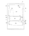
実施例1のパチンコ機について説明する。図1はパチンコ機10の正面図であり、図2は、外枠11に対して内枠12と前面枠セット14とを開放した状態を示す斜視図である。但し、図2では便宜上、下皿ユニット13が内枠12から取り外された状態を示している。
The pachinko machine of Example 1 will be described. FIG. 1 is a front view of the
図1,2に示すように、パチンコ機10は、当該パチンコ機10の外殻を形成する外枠11と、この外枠11の一側部に開閉可能に支持された内枠12とを備えている。以下に、外枠11と内枠12との構成を個別に詳細に説明する。
As shown in FIGS. 1 and 2, the
外枠11は、木製の板材により全体として矩形状に構成され、小ネジ等の離脱可能な締結具により各板材が組み付けられている。本実施の形態では、外枠11の上下方向の外寸は809mm(内寸771mm)、左右方向の外寸は518mm(内寸480mm)となっている。なお、外枠11は樹脂やアルミニウム等の軽金属により構成されていてもよい。
The
内枠12の開閉軸線はパチンコ機10の正面からみてハンドル(後述する遊技球発射ハンドル18)設置箇所の反対側(図1のパチンコ機10の左側)で上下に延びるように設定されており、この開閉軸線を軸心にして内枠12が前方側に十分に開放できるようになっている。例えば、内枠12の開閉軸線がハンドル設置箇所側(図1のパチンコ機10の右側)で上下方向にあるとすると、内枠12を開放する際に遊技球発射ハンドル18の頭部等が隣なりのパチンコ機やカードユニット(球貸しユニット)に干渉することになり、内枠12を十分に開放できない。また、内枠12は合成樹脂、具体的にはABS(アクリロニトリル−ブタジエン−スチレン)樹脂により構成されている。こうすることで、粘性が高く衝撃に強くでき、低コストで製造できる。
The opening / closing axis of the
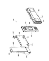
内枠12の構成を図3も用いて詳細に説明する。図3は、パチンコ機10から前面枠セット14を取り外した状態を示す正面図である(但し、図3では便宜上、遊技盤30面上の遊技領域内の構成を空白で示している)。
The configuration of the
内枠12は、大別すると、その最下部に取り付けられた下皿ユニット13と、この下皿ユニット13よりも上側の範囲で内枠12の左側の上下方向の開閉軸線を軸心にして開閉自在に取り付けられた前面枠セット14と、後述する樹脂ベース20と、この樹脂ベース20の後側に取り付けられる遊技盤30とを備えている。これらの各構成を以下に詳細に説明する。
The
下皿ユニット13は、内枠12に対してネジ等の締結具により固定されている。この下皿ユニット13の前面側には、下皿15と球抜きレバー17と遊技球発射ハンドル18と灰皿22と音出力口24が設けられている。球受皿としての下皿15は、下皿ユニット13のほぼ中央部に設けられており、排出口16より排出された遊技球が下皿15内に貯留可能になっている。球抜きレバー17は、下皿15内の遊技球を抜くためのものであり、この球抜きレバー17を図1で左側に移動させることにより、下皿15の底面の所定箇所が開口され、下皿15内に貯留された遊技球を下皿15の底面の開口部分を通して下方向外部に抜くことができる。遊技球発射ハンドル18は、下皿15よりも右方で手前側に突出して配設されている。遊技者による遊技球発射ハンドル18の操作に応じて、遊技球発射装置38によって遊技球が後述する遊技盤30の方へ打ち込まれるようになっている。遊技球発射装置38は、遊技球発射ハンドル18と後述するセットハンドル228と発射モータ229(図6参照)などで構成されている。なお、上述した遊技球発射装置38が本発明における遊技球発射手段に相当する。音出力口24は、下皿ユニット13内あるいは背面に設けられたスピーカからの音を出力するための出力口である。また、灰皿22は下皿15の左方に設けられている。灰皿22は左右方向(水平方向)の軸線を軸心にして回動(例えば前方側に向けて前回り)するように、その右側が下皿15に片持ち支持されている。
The
なお、下皿ユニット13はその大部分が内枠12と同様、ABS樹脂にて成形されている。こうすることで、粘性が高く衝撃に強くでき、低コストで製造できる。特に、下皿15を形成する表面層と下皿奥方の前面パネル部分とを難燃性のABS樹脂にて成形している。このため、この部分は燃え難くなっている。
Note that most of the
また、前面枠セット14は、図2に示すように、内枠12に対して開閉可能に取り付けられており、内枠12と同様、パチンコ機10の正面からみて左側に上下に延びる開閉軸線を軸心にして前方側に開放できるようになっている。しかも前面枠セット14は内枠12の外側壁(リブ)12b(図3参照)内に嵌まり込むようにして取り付けられている。つまり、この前面枠セット14の側面の少なくとも一部が内枠12の外側壁(リブ)12b内に嵌まり込むようにして取り付けられているので、内枠12と前面枠セット14との隙間から異物(針状あるいは薄板状等のもの)を差し入れるなどの不正行為を防止できるようになっている。また、前面枠セット14は、内枠12と同様に、合成樹脂、具体的にはABS樹脂により構成されているので、粘性が高く衝撃に強くでき、低コストで製造できる。
As shown in FIG. 2, the front frame set 14 is attached to the
一方、前面枠セット14の下部(上述の下皿15の上方位置)には、遊技球の受皿としての上皿19が一体的に設けられている。ここで、上皿19は、遊技球を一旦貯留し、一列に整列させながら遊技球発射装置38の方へ導出するための球受皿である。従来のパチンコ機では前面枠セットの下方に内枠に対し開閉可能な前飾り枠が設けられ、該前飾り枠に上皿が設けられていたのであるが、本実施の形態では前飾り枠が省略され、前面枠セット14に対し直接的に上皿19が設けられている。この上皿19も下皿15と同様、表面層が難燃性のABS樹脂にて成形される構成となっている。
On the other hand, an
ここで、前面枠セット14は、少なくとも遊技球発射ハンドル18に干渉しないようにして本パチンコ機10の下方に拡張して設けられており、具体的な数値を示すと、パチンコ機10の下端から前面枠セット14の下端までの寸法(図1のH1)は、既存の一機種で例えば約201mmであるのに対し、本パチンコ機10では30mm程小さく、約172mmとなっている。また、これに伴いパチンコ機10の下端から上皿19までの寸法(図1のH2)も小さくなっており、既存の一機種では例えば約298mmであるのに対し、本パチンコ機10では261mmとなっている。かかる構成では、上皿19の位置を下げたことにより、球貸し装置のノズル部と上皿19との距離が大きくなって貸し出される遊技球のこぼれ落ちなどが懸念されるが、本実施例では、当該ノズル部からの遊技球を受ける部分(向かって左側部分)で上皿19の周囲壁の一部を高くした(図1の高壁部19a)。これにより、上皿19の位置を下げた構成にあっても貸し遊技球のこぼれ落ち等の不都合が解消されるようになっている。なお、高壁部19aの高さ寸法は、上皿19の下げ寸法に見合うものであればよく、本実施例では25mmとした。
Here, the front frame set 14 is provided to be extended below the
図3に示すように、内枠12は、外形が矩形状の樹脂ベース20を主体に構成されており、樹脂ベース20の中央部には略円形状の窓孔21が形成されている。樹脂ベース20の後側には遊技盤30が着脱可能に装着されている。遊技盤30は四角形状の合板よりなり、その周縁部が樹脂ベース20(内枠12)の裏側に当接した状態で取着されている。従って、遊技盤30の前面部の略中央部分が樹脂ベース20の窓孔21を通じて内枠12の前面側に露出した状態となっている。なお、遊技盤30の上下方向の長さは476mm、左右方向の長さは452mmとなっている(従来と同等サイズ)。
As shown in FIG. 3, the
次に、図4を用いて遊技盤30の構成を説明する。図4は遊技盤30の構成を示す正面図である。遊技盤30は、一般入賞口31、可変入賞装置32、第1の始動口33(例えば作動チャッカ)、第2の始動口34(例えばスルーゲート)、可変表示装置ユニット35等を備えている。これらの一般入賞口31、可変入賞装置32、第1の始動口33(例えば作動チャッカ)、第2の始動口34(例えばスルーゲート)、可変表示装置ユニット35等は、遊技盤30における、ルータ加工によって形成された各貫通孔にそれぞれに配設され、遊技盤30前面側から木ネジ等により取り付けられている。前述の一般入賞口31、可変入賞装置32および第1の始動口33に遊技球が入球し、当該入球が後述する検出スイッチ(入賞口スイッチ221、カウントスイッチ223、作動口スイッチ224等)で検出され、この検出スイッチの出力に基づいて、上皿19(または下皿15)へ所定数の賞品球が払い出される。その他に、遊技盤30にはアウト口36が設けられており、各種入賞装置等に入球しなかった遊技球はこのアウト口36を通って図示しない球排出路の方へと案内されるようになっている。遊技盤30には、遊技球の落下方向を適宜分散、調整等するために多数の釘が植設されているとともに、風車37等の各種部材(役物)が配設されている。
Next, the configuration of the
可変表示装置ユニット35は、第1の始動口33への入賞をトリガとして、識別情報としての第1図柄(例えば特別図柄)を変動表示する第1図柄表示装置42と、第2の始動口34の通過をトリガとして、第2図柄(例えば普通図柄)を変動表示する第2図柄表示装置41とを備えている。
The
第2図柄表示装置41は、第2図柄用の表示部43と保留ランプ44とを有し、遊技球が第2の始動口34を通過する毎に例えば表示部43による表示図柄(普通図柄)が変動し、その変動表示が所定図柄で停止した場合に第1の始動口33が所定時間だけ作動状態となる(開放される)よう構成されている。遊技球が第2の始動口34を通過した回数は最大4回まで保留され、その保留回数が保留ランプ44にて点灯表示されるようになっている。なお、表示部43は、複数のランプの点灯を切り換えることにより変動表示される構成の他、第1図柄表示装置42(液晶表示装置)の一部で変動表示される構成等であっても良い。保留ランプ44も同様に、第1図柄表示装置42の一部で変動表示される構成等であっても良い。なお、上述した第2図柄表示装置41が本発明における普通識別情報変動表示手段に相当する。
The second
第1図柄表示装置42は液晶表示装置として構成されており、後述する表示制御装置45により表示内容が制御される。第1図柄表示装置42には、例えば左、中及び右の3つの図柄列が表示される。各図柄列は複数の図柄によって構成されており、これら図柄が図柄列毎にスクロールされるようにして第1図柄表示装置42に可変表示されるようになっている。なお本実施の形態では、第1図柄表示装置42(液晶表示装置)は8インチサイズの大型の液晶ディスプレイを備える。可変表示装置ユニット35には、第1図柄表示装置42を囲むようにしてセンターフレーム47が配設されている。なお、上述した第1図柄表示装置42が本発明における識別情報変動表示手段に相当し、上述した表示制御装置45が本発明における表示制御手段に相当する。
The first
可変入賞装置32は、通常は遊技球が入賞できない又は入賞し難い閉状態になっており、大当たりの際に遊技球が入賞しやすい開状態と通常の閉状態とに繰り返し作動されるようになっている。より詳しくは、第1の始動口33に対し遊技球が入賞すると第1図柄表示装置42で図柄が変動表示され、その停止後の確定図柄が予め設定した特定の図柄の組合せとなったことを必要条件に特別遊技状態が発生する。そして、可変入賞装置32の大入賞口が所定の開放状態となり、遊技球が入賞しやすい状態(大当たり状態)になるよう構成されている。具体的には、所定時間の経過又は所定個数の入賞を1ラウンドとして、可変入賞装置32の大入賞口が所定回数繰り返し開放される。遊技球が第1の始動口33を通過した回数は最大4回まで保留され、その保留回数が保留ランプ46にて点灯表示されるようになっている。なお、保留ランプ46は、第1図柄表示装置42の一部で変動表示される構成等であっても良い。
The
また、遊技盤30には、遊技球発射装置38から発射された遊技球を遊技盤30上部へ案内するためのレールユニット50が取り付けられており、遊技球発射ハンドル18の回動操作に伴い発射された遊技球はレールユニット50を通じて所定の遊技領域に案内されるようになっている。レールユニット50はリング状をなす樹脂成型品(例えば、フッ素樹脂が添加されて成形されたもの)にて構成されており、内外二重に一体形成された内レール51と外レール52とを有する。なお、レールユニット50はフッ素樹脂を添加して成形されているので、図3に示す奥面50aについての遊技球の摩擦抵抗を少なくできる。内レール51は上方の約1/4ほどを除いて略円環状に形成され、一部(主に左側部)が内レール51に向かい合うようにして外レール52が形成されている。かかる場合、内レール51と外レール52とにより誘導レールが構成され、これら各レール51,52が所定間隔を隔てて並行する部分(向かって左側の部分)により球案内通路が形成されている。なお、球案内通路は、遊技盤30との当接面を有した溝状、すなわち手前側を開放した溝状に形成されている。
Further, the
内レール51の先端部分(図4の左上部)には戻り球防止部材53が取着されている。これにより、一旦、内レール51及び外レール52間の球案内通路から遊技盤30の上部へと案内された遊技球が再度球案内通路内に戻ってしまうといった事態が防止されるようになっている。また、外レール52には、遊技球の最大飛翔部分に対応する位置(図4の右上部:外レール52の先端部に相当する部位)に返しゴム54が取着されている。従って、所定以上の勢いで発射された遊技球は、返しゴム54に当たって跳ね返されるようになっている。外レール52の内側面には、遊技球の飛翔をより滑らかなものとするべく、つまり遊技球の摩擦抵抗を少なくするべく、長尺状をなすステンレス製の金属帯としての摺動プレート55が取着されている。
A return
また、レールユニット50の外周部には、外方へ張り出した円弧状のフランジ56が形成されている。フランジ56は、遊技盤30に対する取付面を構成する。レールユニット50が遊技盤30に取り付けられる際には、遊技盤30上にフランジ56が当接され、その状態で、当該フランジ56に形成された複数の透孔にネジ等が挿通されて遊技盤30に対するレールユニット50の締結がなされるようになっている。この実施例では、レールユニット50の少なくとも左側を遊技盤30に強固に締結するために、レールユニット50の左側はその右側よりも多いネジで遊技盤30に締結されているので、レールユニット50の左側についての遊技盤30への密着性を上げることができ、遊技球の球飛びを良くすることができる。レールユニット50の左側が遊技盤30に対してぐらついているとこのレールユニット50に出射された遊技球の勢いが当該ぐらつきにより吸収されてしまうからである。
An arc-shaped
さらに本実施の形態では、正面から見てレールユニット50の上下左右の各端部は略直線状に(平坦に)形成されている。つまり、レールユニット50の上下左右の各端部においてはフランジ56が切り落とされ、パチンコ機10における有限の領域にてレール径の拡張、すなわち遊技盤30上の遊技領域の拡張が図られるようになっている。
Furthermore, in the present embodiment, the top, bottom, left, and right ends of the
内レール51及び外レール52間の球案内通路の入口には、同球案内通路の一部を閉鎖するようにして凸部57が形成されている。この凸部57は、内レール51からレールユニット50下端部にかけて略鉛直方向に設けられ、遊技領域まで至らず球案内通路内を逆流してくるファール球をファール球通路63(図3参照)に導くための役目をなす。なお、遊技盤30の右下隅部及び左下隅部は、証紙(例えば製造番号が記載されている)等のシール(図4のS1,S2)やプレートを貼着するためのスペースとなっており、この貼着スペースを確保するために、フランジ56に切欠58,59が形成されている。遊技盤30の右下隅部や左下隅部に、証紙等のシール(図4のS1,S2)を貼着することで、遊技盤30と証紙との一義性を持たせることができる。
A
次に、遊技領域について説明する。遊技領域は、レールユニット50の内周部(内外レール)により略円形状に区画形成されており、特に本実施の形態では、遊技盤30の盤面上に区画される遊技領域が従来よりもはるかに大きく構成されている。本実施の形態では、外レール52の最上部地点から遊技盤30下部までの間の距離は445mm(従来品よりも58mm長い)、外レール52の極左位置から内レール51の極右位置までの間の距離は435mm(従来品よりも50mm長い)となっている。また、内レール51の極左位置から内レール51の極右位置までの間の距離は418mmとなっている。
Next, the game area will be described. The game area is partitioned and formed in a substantially circular shape by the inner peripheral portion (inner and outer rails) of the
本実施の形態では、遊技領域を、パチンコ機10の正面から見て、内レール51及び外レール52によって囲まれる領域のうち、内外レール51,52の並行部分である誘導レールの領域を除いた領域としている。従って、遊技領域と言った場合には誘導レール部分は含まないため、遊技領域の向かって左側限界位置は外レール52によってではなく内レール51によって特定される。同様に、遊技領域の向かって右側限界位置は内レール51によって特定される。また、遊技領域の下側限界位置は遊技盤30の下端位置によって特定される。また、遊技領域の上側限界位置は外レール52によって特定される。
In the present embodiment, the game area is a region surrounded by the
従って、本実施の形態では、遊技領域の幅(左右方向の最大幅)は、418mmであり、遊技領域の高さ(上下方向の最大幅)は、445mmである。 Therefore, in the present embodiment, the width of the game area (maximum width in the left-right direction) is 418 mm, and the height of the game area (maximum width in the vertical direction) is 445 mm.
ここで、前記遊技領域の幅は、少なくとも380mm以上あることが望ましい。より好ましくは390mm以上、400mm以上、410mm以上、420mm以上、430mm以上、440mm以上、450mm以上、さらに460mm以上であることが望ましい。もちろん、470mm以上であってもよい。すなわち、遊技領域の幅は、遊技領域拡大という観点からは大きい程好ましい。また、遊技領域の高さは、少なくとも400mm以上あることが望ましい。より好ましくは410mm以上、420mm以上、430mm以上、440mm以上、450mm以上、さらには460mm以上であることがより望ましい。もちろん、470mm以上、480mm以上、490mm以上としてもよい。すなわち、遊技領域の高さは、遊技領域拡大という観点からは大きい程好ましい。なお、上記幅及び高さの組合せについては、上記数値を任意に組み合わせたものとしてもよい。 Here, the width of the gaming area is preferably at least 380 mm. More preferably, it is 390 mm or more, 400 mm or more, 410 mm or more, 420 mm or more, 430 mm or more, 440 mm or more, 450 mm or more, and further 460 mm or more. Of course, it may be 470 mm or more. That is, the width of the game area is preferably as large as possible from the viewpoint of game area expansion. The height of the game area is preferably at least 400 mm. More preferably, it is 410 mm or more, 420 mm or more, 430 mm or more, 440 mm or more, 450 mm or more, and more preferably 460 mm or more. Of course, it is good also as 470 mm or more, 480 mm or more, and 490 mm or more. In other words, the height of the game area is preferably as large as possible from the viewpoint of expanding the game area. In addition, about the combination of the said width | variety and height, it is good also as what combined the said numerical value arbitrarily.
本実施の形態では、遊技盤30面に対する遊技領域の面積の比率は約70%と、従来に比べ格段に面積比が大きいものとなっている。なお、遊技盤30面に対する遊技領域の面積比は、従来では50%程度に過ぎなかったことから、遊技盤30を共通とした前提においてはかなり遊技領域を拡大しているといえる。尚、パチンコ機10の外形は遊技場への設置の都合上製造者間でほぼ統一されており、遊技盤30の大きさも同様とせざるを得ない状況下において、上記のように遊技盤30面に対する遊技領域の面積の比率を約20%も高めたことは、遊技領域拡大の観点で非常に有意義である。ここで、前記比率は、少なくとも60%以上であることが望ましい。さらに好ましくは65%以上であり、より好ましくは70%以上である。また、本実施形態の場合を越えて75%以上であれば、一層望ましい。さらには、80%以上であってもよい。
In the present embodiment, the ratio of the area of the game area to the surface of the
また、パチンコ機10全体の正面側の面積に対する遊技領域の面積の比率は約40%と、従来に比べ格段に面積比が大きいものとなっている。なお、パチンコ機10全体の正面側の面積に対する遊技領域の面積比は、35パーセント以上であるのが望ましい。もちろん、40パーセント以上としてもよいし、45パーセント以上、又は50パーセント以上としてもよい。
Further, the ratio of the area of the game area to the area of the front side of the
なお、可変表示装置ユニット35の両側に位置する第2の始動口34は、該第2の始動口34を通過した遊技球が中央の方へ寄せられるような案内機構を有している。これにより、遊技領域が左右方向に拡張されている場合であっても、遊技球を中央の第1の始動口33や可変入賞装置32の方へと案内することができ、ひいては、遊技領域が拡張されることにより遊技球が入賞しにくくなることによる興趣の低下が抑制されるようになっている。さらには、遊技領域が左右方向に拡張されていることによって、風車37、第2の始動口34、複数の釘(遊技球を中央に誘導するための誘導釘)、他の役物を種々配設することができ、可変表示装置ユニット35の左右両側の遊技領域での遊技球の挙動を一層面白くすることができるようになっている。また、遊技領域が上下方向にも拡張されていることから、さらに風車37、第2の始動口34、複数の釘、他の役物を種々配設することができ、遊技領域での上下方向の遊技球の挙動をより一層面白くすることができるようになっている。
In addition, the 2nd starting
図3の説明に戻り、前記樹脂ベース20において、窓孔21(遊技盤30)の下方には、遊技球発射装置38より発射された直後に遊技球を案内するための発射レール61が取り付けられている。発射レール61は、その後方の金属板62を介して樹脂ベース20に取付固定されており、所定の発射角度(打ち出し角度)にて直線的に延びるよう構成されている。従って、遊技球発射ハンドル18の回動操作に伴い発射された遊技球は、まずは発射レール61に沿って斜め上方に打ち出され、その後前述した通りレールユニット50の球案内通路を通じて所定の遊技領域に案内されるようになっている。
Returning to the description of FIG. 3, in the
本パチンコ機10の場合、遊技領域が従来よりも大幅に拡張されることは既に述べたが、かかる構成下では、誘導レールの曲率を小さくせざるを得ないことから、打出球を安定化させるための工夫を要する。そこで本実施の形態では、遊技球の発射位置を低くするとともに発射レール61の傾斜角度(発射角度)を既存のものよりも幾分大きくし(すなわち発射レール61を立ち上げるようにし)、さらに発射レール61の長さを既存のものよりも長くして十分な長さの球誘導距離を確保するようにしている。これにより、遊技球発射装置38から発射された遊技球をより安定した状態で誘導レールに案内できるようにしている。この場合特に、発射レール61を、遊技球発射装置38の発射位置から遊技領域の中央位置(アウト口36)を越える位置まで延びるよう形成している。
In the case of this
また、発射レール61とレールユニット50(誘導レール)との間には所定間隔の隙間があり、この隙間より下方にファール球通路63が形成されている。従って、仮に、遊技球発射装置38から発射された遊技球が戻り球防止部材53まで至らずファール球として誘導レール内を逆戻りする場合には、そのファール球がファール球通路63を介して下皿15に排出される。因みに、本実施の形態の場合、発射レール61の長さは約240mm、発射レール先端部の隙間の長さ(発射レール61の延長線上の長さ)は約40mmである。
Further, there is a gap of a predetermined interval between the firing
ファール球が誘導レール内を逆流してくる際、その多くは外レール52に沿って流れ、外レール52の下端部に到達した時点で下方に落下するが、一部のファール球は誘導レール内で暴れ、内レール51側へ跳ね上がるものもある。この際、跳ね上がったファール球は、球案内通路入口の前記凸部57に当たり、ファール球通路63に誘導される。これにより、ファール球の全てがファール球通路63に確実に案内されるようになる。これにより、ファール球と次に発射される遊技球との干渉が抑制される。
When the foul spheres flow backward in the guide rail, most of them flow along the
なお、詳しい図面の開示は省略するが、遊技球発射装置38には、前面枠セット14側の球出口(上皿19の最下流部より通じる球出口)から遊技球が1つずつ供給される。この際、本実施の形態では遊技球の発射位置を低くしたため、前面枠セット14側の球出口から前記発射位置への落差が大きくなるが、発射レール61の基端部付近にはその右側と手前側にそれぞれガイド部材65,66を設置した。これにより、前面枠セット14側の球出口から供給される遊技球が常に所定の発射位置にセットされ、安定した発射動作が実現できる。また、遊技球発射装置38には打球槌が設けられ、軸部を中心とする打球槌の回動に伴い遊技球が発射されるが、打球槌に関して軽量化が望まれている。それ故、アルミニウム等の軽金属への材料変更や軸部寸法の縮小化により打球槌の軽量化を図る一方で、十分な発射力を確保すべく、打球槌のヘッド部(軸部と反対側の端部)に重り部を設けている。これにより、十分でかつ安定した遊技球の発射が実現できる。打球槌の重り部を上方に突出して設けることにより、打球槌を容易に摘んだりひっかけたりすることができ、槌先の打球強さの調整等がし易くなるという効果がある。
Although detailed disclosure of the drawings is omitted, game balls are supplied to the
なお、図3中の符号67は上皿19に通ずる排出口であり、この排出口67を介して遊技球が上皿19に排出される。排出口67には、略水平方向の回転軸を軸心として略水平状態と略垂直状態とに変位する開閉式のシャッタ68が取り付けられている。前面枠セット14を内枠12から開放した状態(図3の状態)では、バネ等の付勢力によりシャッタ68が略水平状態から略垂直状態となり、排出口67から遊技球がこぼれ落ちないようにこの排出口67を閉鎖する。また、前面枠セット14を閉鎖した状態では、当該前面枠セット14の裏面に設けられた球通路樋69(図2参照)によりシャッタ68が押し開けられて略水平状態になり、排出口67の方へ排出された遊技球はもれなく球通路樋69を通って上皿19に排出されるようになる。従って、前飾り枠が省略され前面枠セット14に対して上皿19が直接設けられる構成とした本パチンコ機10において、前面枠セット14の開放に際し払出通路内等の遊技球がパチンコ機10外にこぼれ落ちてしまうといった不都合が防止できるようになっている。
In addition, the code |
樹脂ベース20には、窓孔21の右下部に略四角形状の小窓71が設けられている。従って、遊技盤30の右下隅部に張られた証紙などのシール(図4のS1)は、この小窓71を通じて視認できるようになっている。また、この小窓71からシール等を貼り付けることも可能となっている。
The
また、図3に示すように、内枠12の左端部には、前面枠セット14の支持機構として、支持金具81,82が取り付けられている。上側の支持金具81には図の手前側に切欠を有する支持孔83が設けられ、下側の支持金具82には鉛直方向に突出した突起軸84が設けられている。
As shown in FIG. 3,
図3に示すように、内枠12の上側には、前面枠セット14が内枠12に対して開かれたことを検出する前面枠セット開検出スイッチ90が設けられている。前面枠セット14が開かれると、前面枠セット開検出スイッチ90からホール内(パチンコ店内)用コンピュータへ出力されるようになっている。また、前面枠セット14が閉じられると、図5に示す前面枠セット14の金属製の補強板132,131が図3に示す内枠12の一対の金具92に接触するようになっており、前面枠セット14のアースが確保されている。
As shown in FIG. 3, a front frame set
ここで、前述した前面枠セット14について、図1,図5を参照しつつより詳細に説明する。図5は、前面枠セット14の背面図である。前面枠セット14には前記遊技領域のほとんどを外部から視認することができるよう略楕円形状の窓部101が形成されている。詳しくは、窓部101は、その左右側の略中央部が、上下側に比べて比較的緩やかに湾曲した形状となっている。なお、前記略中央部が直線状になるようにしてもよい。本実施の形態において、窓部101の上端(外レール52の最上部、遊技領域の上端)と、前面枠セット14の上端との間の距離(いわゆる上部フレーム部分の上下幅)は61mmとなっており、85mm〜95mm程度上部フレーム幅がある従来技術に比べて著しく短くなっている。これにより、遊技領域の上部領域が確保されやすくなるとともに、大型の可変表示装置ユニット35も比較的上方に配置することができるようになっている。前面枠セット14の上端との間の距離は80mm以下であることが望ましく、より望ましくは70mm以下であり、さらに望ましくは60mm以下である。もちろん、所定の強度が確保できるのであれば、50mm以下であっても差し支えない。
Here, the front frame set 14 described above will be described in more detail with reference to FIGS. FIG. 5 is a rear view of the front frame set 14. The front frame set 14 is formed with a substantially
また、パチンコ機10の正面から見て窓部101の左端と前面枠セット14の左端との間の最短距離(いわゆる左側部フレーム部分の左右幅:図5では右側に示されている)、すなわち開閉軸線側のフレーム幅は、前面枠セット14自体の強度及び支持強度を高めるために比較的大きく設定されている。この場合、図1及び図3を相互に比較すると明らかなように、前面枠セット14が閉じられた状態において、外レール52の左端部はもちろん、内レール51の左端部も前記左側部フレーム部分によって覆い隠される。つまり、誘導レールの少なくとも一部が、パチンコ機10の正面からみて前面枠セット14の左側部フレーム部分と重複し覆い隠される。このように遊技球が一時的に視認困難となったとしても、それは、遊技球が遊技領域に案内される通過点に過ぎず、遊技者が主として遊技を楽しむ遊技領域において遊技球が視認困難となるわけではない。そのため、実際の遊技に際しては何ら支障が生じない。また、このような支障が生じない一方で、前面枠セット14の十分な強度及び支持強度が確保可能となっている。ちなみに、パチンコ機10の正面から見て外レール52の左端位置と外枠11の左端位置との左右方向の距離は21mm、遊技領域の右端位置(内レール51の右端位置)と外枠11の右端位置との左右方向の距離は44mmとなっている。
Further, the shortest distance between the left end of the
加えて、前面枠セット14にはその周囲(例えばコーナー部分)に各種ランプ等の発光手段が設けられている。これら発光手段は、大当たり時や所定のリーチ時等における遊技状態の変化に応じて点灯、点滅のように発光態様が変更制御され遊技中の演出効果を高める役割を果たすものである。例えば、窓部101の周縁には、LED等の発光手段を内蔵した環状電飾部102が左右対称に設けられ、該環状電飾部102の中央であってパチンコ機10の最上部には、同じくLED等の発光手段を内蔵した中央電飾部103が設けられている。本パチンコ機10では、中央電飾部103が大当たりランプとして機能し、大当たり時に点灯や点滅を行うことにより、大当たり中であることを報知する。さらに、上皿19周りにも、同じくLED等の発光手段を内蔵した上皿電飾部104が設けられている。その他、中央電飾部103の左右側方には、賞球払出し中に点灯する賞球ランプ105と所定のエラー時に点灯するエラー表示ランプ106とが設けられている。また、環状電飾部102の下端部に隣接するようにして、内枠12表面や遊技盤30表面等の一部を視認できるよう透明樹脂からなる小窓107が設けられている。この小窓107の所定箇所を平面状としているので、遊技盤30の右下隅部に貼り付けられた証紙などを、小窓107の当該平面状箇所から機械で好適に読み取ることができる。
In addition, the front frame set 14 is provided with light emitting means such as various lamps around it (for example, a corner portion). These light emitting means play a role of enhancing the effect of the game during the game by changing and controlling the light emission mode such as lighting and blinking according to the change of the game state at the time of big hit or predetermined reach. For example, at the periphery of the
また、窓部101の下方には貸球操作部120が配設されており、貸球操作部120には球貸しボタン121と、返却ボタン122と、度数表示部123とが設けられている。パチンコ機10の側方に配置された図示しないカードユニット(球貸しユニット)に紙幣やカード等を投入した状態で貸球操作部120が操作されると、その操作に応じて遊技球の貸出が行われる。球貸しボタン121は、カード等(記録媒体)に記録された情報に基づいて貸出球を得るために操作されるものであり、カード等に残額が存在する限りにおいて貸出球が上皿19に供給される。返却ボタン122は、カードユニットに挿入されたカード等の返却を求める際に操作される。度数表示部123はカード等の残額情報を表示するものである。なお、カードユニットを介さずに球貸し装置等から上皿に遊技球が直接貸し出されるパチンコ機、いわゆる現金機では貸球操作部120が不要となる。故に、貸球操作部120の設置部分に、飾りシール等が付されるようになっている。これにより、カードユニットを用いたパチンコ機と現金機との貸球操作部の共通化が図れる。
In addition, a ball
また、図1に示すように、前面枠セット14の左側の小窓107付近を前面側(図1の紙面手前側)に必要以上に突出しないようにしている。こうすることで、パチンコ機10の左側に設けられたカードサンドの球貸し装置から直接に上皿19に遊技球を貸し出す際に、当該球貸し装置のノーズ部(いわゆる象の鼻)の先端排出口を好適に上皿19の上方位置に位置させることができ、当該球貸し装置のノーズ部から貸し出される遊技球を上皿19で受けることができる。
Further, as shown in FIG. 1, the vicinity of the
前面枠セット14の裏側には、窓部101を囲むようにして金属製の各種補強部材が設けられている。詳しくは、図5に示すように、前面枠セット14の裏側にあって窓部101の上下左右の外側にはそれぞれ補強板131,132,133,134が取り付けられている。これら補強板131〜134は相互に接触して連結されているが、図の左側及び上側の補強板132,133の連結部には直接の接触を避けるための樹脂パーツ135が介在されている。このように補強板132,133の連結部に樹脂パーツ135を介在させているので、ノイズが補強板131〜134でループすることを防止できる。また、図5の右側の補強板131にはその中間位置にフック状をなす係合爪131aが設けられており、この係合爪131aは、前面枠セット14を閉じた状態で内枠12の孔部12a(図3参照)に係合されるように構成されている。この構成により、上皿19を含む形態で前面枠セット14が構成され、その上下の軸支位置が延長されたとしても、中間位置における前面枠セット14の浮き上がりが防止できる。それ故、前面枠セット14を浮かしての不正行為等が抑制されるようになっている。
Various reinforcing members made of metal are provided on the back side of the front frame set 14 so as to surround the
また、下側の補強板134には、前記発射レール61(図3参照)に対向する位置に樹脂製のレール側壁部材136が設けられている。このレール側壁部材136は、前面枠セット14を閉じた際に発射レール61の側壁となる。故に、発射レール61から遊技球がこぼれ落ちないようになっている。
The lower reinforcing
上述した補強板131〜134はガラス支持用の金枠としての機能も兼ね備えており、これら補強板131〜134の一部が後方に折り返されてガラス保持溝が形成されている。このガラス保持溝は前後に2列形成されており、矩形状をなす前後一対のガラス137が各ガラス保持溝にて保持される。これにより、2枚のガラス137が前後に所定間隔を隔てて取着されるようになっている。
The reinforcing
前述の通り本実施の形態のパチンコ機10では遊技領域の拡張を図っていることから、前面枠セット14を閉じた状態にあっては、内外のレール52,53により構成された誘導レールの一部が前面枠セット14により覆い隠される構成となっている。それ故、当該誘導レールでは手前側の開放部がガラス137で覆えない部分ができてしまう。かかる場合、例えば、遊技球発射装置38より発射された遊技球が戻り球防止部材53まで至らず戻ってくると、当該遊技球が誘導レール外にこぼれたり(飛び出したり)、外レール52とガラス137との間に挟まってしまうおそれがある。そこで本実施の形態では、前面枠セット14に、誘導レールの手前側開放部を被覆するためのレールカバー140を取り付けている。
As described above, in the
レールカバー140は略円弧状をなす略平板体であって、透明な樹脂により形成されている。レールカバー140は、その円弧形状が前記誘導レールの形状に対応しており、窓部101の周縁部に沿って、誘導レールの基端部から先端部近傍までの区間を覆うようにして前面枠セット14の裏側に取着されている。特にレールカバー140の内径側の寸法・形状は内レール52のそれにほぼ一致する。レールカバー140が取着された状態では、その表面側がガラス137に当接した状態となる。前面枠セット14が閉じられた状態においては、レールカバー140の裏面が誘導レールのほぼ全域を覆うこととなる。これにより、誘導レールのほとんどの区間において遊技球のガラス137への衝突を防止できる。従って、ガラス137への接触による破損等の悪影響を抑制することができる。
The
また、レールカバー140の右端部(すなわち、レールカバー140を前面枠セット14に取着した図5の状態で右端となる部位)には、誘導レールがガラス137の側縁部からはみ出した部分を被覆するための被覆部141が設けられている。これにより、遊技球が誘導レール外にこぼれたり(飛び出したり)、外レール52とガラス137との間に挟まってしまうといった不具合の発生を防止することができる。
Further, a portion where the guide rail protrudes from the side edge portion of the
さらに、レールカバー140の裏側には、その内側縁に沿って円弧状に延び且つ図5の手前側に突出した突条142が形成されている。突条142は、前面枠セット14が閉じられた状態において、誘導レール内に入り込んだ状態で内レール52にほぼ一体的に重なり合うよう構成されている。従って、例えば前面枠セット14と内枠12との隙間から針金等を侵入させて不正行為を行おうとしても、誘導レールの内側にある遊技領域にまで針金等を侵入させることが非常に困難となる。結果として、針金等を利用して行われる不正行為を防止することができる。なお、突条142をより広い範囲で、例えばレールカバー140の内側縁の全域に沿って形成する構成としても良く、かかる構成によれば、より広い範囲で針金等を侵入させにくくなり、針金等を利用して行われる不正行為をより確実に防止することができる。
Further, on the back side of the
また、前面枠セット14の図5の右端部(パチンコ機10正面から見ると左端部)には、内枠12の支持機構として、支持金具151,152が取り付けられている。従って、内枠12側の支持金具81,82(図3参照)に対して前面枠セット14側の支持金具151,152を組み付けることで、内枠12に対して前面枠セット14が開閉可能に装着されるようになる。
Further,
次に、パチンコ機10の背面の構成を詳しく説明する。図6はパチンコ機10の背面図であり、図7はパチンコ機10の背面構成を主要部品毎に分解して示す分解斜視図である。
Next, the configuration of the back surface of the
先ず、パチンコ機10の背面構成について全体の概要を説明する。パチンコ機10にはその背面(実際には内枠12及び遊技盤30の背面)において、各種制御基板が上下左右に並べられるようにして又は前後に重ねられるようにして配置されており、さらに、遊技球を供給するための遊技球供給装置(払出機構)や樹脂製の保護カバー等が取り付けられている。本実施の形態では、各種制御基板を2つの取付台に分けて搭載して2つの制御基板ユニットを構成し、それら制御基板ユニットを個別に内枠12又は遊技盤30の裏面に装着するようにしている。この場合、主基板と音声ランプ制御基板とを一方の取付台に搭載してユニット化すると共に、払出制御基板、発射制御基板及び電源基板を他方の取付台に搭載してユニット化している。ここでは便宜上、前者のユニットを「第1制御基板ユニット201」と称し、後者のユニットを「第2制御基板ユニット202」と称することとする。
First, an overall outline of the rear configuration of the
また、払出機構及び保護カバーも1ユニットとして一体化されており、一般に樹脂部分を裏パックと称することもあるため、ここではそのユニットを「裏パックユニット203」と称する。各ユニット201〜203の詳細な構成については後述する。
Further, since the dispensing mechanism and the protective cover are integrated as one unit, and the resin portion is generally referred to as a back pack, the unit is referred to as a “
第1制御基板ユニット201、第2制御基板ユニット202及び裏パックユニット203は、ユニット単位で何ら工具等を用いずに着脱できるよう構成されており、さらにこれに加え、一部に支軸部を設けて内枠12又は遊技盤30の裏面に対して開閉できる構成となっている。これは、各ユニット201〜203やその他構成が前後に重ねて配置されても、隠れた構成等を容易に確認することを可能とするための工夫でもある。
The first
実際には、図8の概略図に示すように各ユニット201〜203が配置され、取り付けられている。なお図8において、略L字状をなす第1制御基板ユニット201はパチンコ機10のほぼ中央に配置され、その下方に第2制御基板ユニット202が配置されている。また、第1制御基板ユニット201に一部重なる領域に、裏パックユニット203が配置されている。
Actually, the
詳しくは、第1制御基板ユニット201には、パチンコ機10の背面から見て左端部に支軸部M1が設けられ、その支軸部M1による軸線Aを中心に当該第1制御基板ユニット201が開閉可能となっている。また、第1制御基板ユニット201には、その右端部(すなわち支軸部と反対側、さらに言えば開放端側)にナイラッチ等よりなる締結部M2が設けられると共に上端部に係止爪部M3が設けられており、これら締結部M2及び係止爪部M3によって第1制御基板ユニット201がパチンコ機本体に対して固定保持されるようになっている。
Specifically, the first
また、第2制御基板ユニット202には、パチンコ機10の背面から見て右端部に支軸部M4が設けられ、その支軸部M4による軸線Bを中心に当該第2制御基板ユニット202が開閉可能となっている。また、第2制御基板ユニット202には、その左端部(すなわち支軸部と反対側、さらに言えば開放端側)にナイラッチ等よりなる締結部M5が設けられており、この締結部M5によって第2制御基板ユニット202がパチンコ機本体に対して固定保持されるようになっている。
Further, the second
さらに、裏パックユニット203には、パチンコ機10の背面から見て右端部に支軸部M6が設けられ、その支軸部M6による軸線Cを中心に当該裏パックユニット203が開閉可能となっている。また、裏パックユニット203には、その左端部(すなわち支軸部と反対側、さらに言えば開放端側)にナイラッチ等よりなる締結部M7が設けられると共に上端部及び下端部にそれぞれ回動式の係止部M8,M9が設けられており、これら締結部M7及び係止部M8,M9によって裏パックユニット203がパチンコ機本体に対して固定保持されるようになっている。
Further, the
この場合、各ユニット201〜203の展開方向は同一でなく、第1制御基板ユニット201は、パチンコ機10の背面から見て左開きになるのに対し、第2制御基板ユニット202及び裏パックユニット203は、同右開きになるよう構成されている。
In this case, the development directions of the
一方、図9は、内枠12に遊技盤30を組み付けた状態でその構成を示す背面図である。また、図10は内枠12を後方より見た斜視図であり、図11は遊技盤30を後方より見た斜視図である。ここでは図9〜図11を用いて内枠12及び遊技盤30の裏面構成を説明する。
On the other hand, FIG. 9 is a rear view showing the configuration in a state where the
遊技盤30は、樹脂ベース20に囲まれた四角枠状の設置領域に設置され、内枠12に設けられた複数(本実施の形態では4カ所)の係止固定具211,212によって脱落しないように固定されている。係止固定具211,212は手動で回動でき、固定位置(ロック位置)と固定解除位置(アンロック位置)とを切り換えることができるよう構成されており、図9にはロック状態を示す。遊技盤30の左右3カ所の係止固定具211は金属片を折り曲げ形成したL型の金具であり、遊技盤30の固定状態で内枠外方へ張り出さないよう構成されている。なお、遊技盤30の下部1カ所の係止固定具212は樹脂製のI型の留め具である。
The
遊技盤30の中央には可変表示装置ユニット35が配置されている。可変表示装置ユニット35においては、センターフレーム47(図3参照)を背後から覆う樹脂製(例えばABS製)のフレームカバー213が後方に突出して設けられており、そのフレームカバー213の後端に、液晶表示装置たる第1図柄表示装置42と表示制御装置45とが前後に重ねられた状態で着脱可能に取り付けられている。フレームカバー213内には、センターフレーム47に内蔵されたLED等を駆動するためのLED制御基板などが配設されている。
A variable
また、遊技盤30の裏面には、可変表示装置ユニット35を取り囲むようにして裏枠セット215が取り付けられている。この裏枠セット215は、遊技盤30の裏面に張り付くようにして設けられる薄型の樹脂成型品(例えばABS製)であって、各種入賞口に入賞した遊技球を回収するための遊技球回収機構が形成されている。詳しくは、裏枠セット215の下方には、前述した一般入賞口31、可変入賞装置32、第1の始動口33(それぞれ図3参照)の遊技盤開口部に対応し、且つ下流側で1カ所に集合する回収通路216が形成されている。また、遊技盤30の下方には、内枠12にやはり樹脂製(例えばポリカーボネート樹脂製)の排出通路盤217が取り付けられており、該排出通路盤217には、排出球をパチンコ機10外部へ案内するための排出通路218が形成されている。従って、図9に仮想線で例示するように、一般入賞口31等に入賞した遊技球は何れも裏枠セット215の回収通路216を介して集合し、さらに排出通路盤217の排出通路218を介してパチンコ機10外部に排出される。なお、アウト口36(図3参照)も同様に排出通路218に通じており、何れの入賞口にも入賞しなかった遊技球も排出通路218を介してパチンコ機10外部に排出される。
A back frame set 215 is attached to the back surface of the
上記構成では、遊技盤30の下端面を境界にして、上方に裏枠セット215(回収通路216)が、下方に排出通路盤217(排出通路218)が設けられており、排出通路盤217が遊技盤30に対して前後方向に重複(オーバーラップ)せずに設けられている。従って、遊技盤30を内枠12から取り外す際において、排出通路盤217が遊技盤取り外しの妨げになるといった不都合が生じることもない。
In the above configuration, with the lower end surface of the
なお、排出通路盤217は、パチンコ機前面の上皿19の丁度裏側辺りに設けられており、上皿19に至る球排出口(図2の球通路樋69)より針金等を差し込み、さらにその針金等を内枠12と排出通路盤217との隙間を通じて遊技領域側に侵入させるといった不正行為が考えられる。そこで本パチンコ機10では、排出通路盤217の上皿19の丁度裏側辺りに、内枠12にほぼ一体的に重なり合うようにしてパチンコ機前方に延びるプレート219が設けられている。従って、内枠12と排出通路盤217との隙間から針金等を侵入させようとしてもそれがプレート219にて阻害され、遊技領域にまで針金等を侵入させることが非常に困難となる。結果として、針金等を利用して可変入賞装置32(大入賞口)を強制的に開放する等の不正行為を防止することができる。
The
また、遊技盤30の裏面には、各種入賞口などの遊技球の通過を検出するための入賞感知機構などが設けられている。具体的には、遊技盤30表側の一般入賞口31に対応する位置には入賞口スイッチ221が設けられ、可変入賞装置32には、特定領域スイッチ222とカウントスイッチ223とが設けられている。特定領域スイッチ222は、大当たり状態で可変入賞装置32に入賞した遊技球が特定領域(大当たり状態継続を判定するための領域)に入ったことを判定するスイッチであり、カウントスイッチ223は入賞球をカウントするスイッチである。また、第1の始動口33に対応する位置には作動口スイッチ224が設けられ、第2の始動口34に対応する位置にはゲートスイッチ225が設けられている。なお、上述した作動口スイッチ224が本発明における入賞検出手段に相当する。
In addition, on the back surface of the
入賞口スイッチ221及びゲートスイッチ225は、図示しない電気配線を通じて盤面中継基板226に接続され、さらにこの盤面中継基板226が後述する主基板(主制御装置)に接続されている。また、特定領域スイッチ222及びカウントスイッチ223は大入賞口中継基板227に接続され、さらにこの大入賞口中継基板227がやはり主基板に接続されている。これに対し、作動口スイッチ224は中継基板を介さずに直接主基板に接続されている。
The
その他図示は省略するが、可変入賞装置32には、大入賞口を開放するための大入賞口ソレノイドと、入賞球を特定領域に導くための入賞球振分板ソレノイドが設けられ、第1の始動口33には、電動役物を開放するための作動口ソレノイドが設けられている。なお、図9において符号228は打球槌等を備えるセットハンドルであり、符号229は発射モータである。
Although not shown in the drawings, the variable
上記入賞感知機構にて各々検出された検出結果は、後述する主基板に取り込まれ、該主基板よりその都度の入賞状況に応じた払出指令(遊技球の払出個数)が払出制御基板に送信される。そして、該払出制御基板の出力により所定数の遊技球の払出が実施される。かかる場合、各種入賞口に入賞した遊技球を入賞球処理装置に一旦集め、その入賞球処理装置で入賞球の存在を1つずつ順番に確認した上で払出を行う従来方式(いわゆる証拠球方式)とは異なり、本実施の形態のパチンコ機10では、各種入賞口毎に遊技球の入賞を電気的に感知して払出が直ちに行われる(すなわち、本パチンコ機10では入賞球処理装置を廃止している)。故に、払い出す遊技球が多量にあっても、その払出をいち早く実施することが可能となる。但し、本発明に従来の「証拠球方式」を適用してもよい。
The detection results detected by the winning detection mechanism are taken into a main board, which will be described later, and a payout command (the number of game balls to be paid out) corresponding to the winning situation is transmitted from the main board to the payout control board. The Then, a predetermined number of game balls are paid out by the output of the payout control board. In such a case, a conventional method (so-called evidence ball method) in which game balls won in various winning openings are once collected in a winning ball processing device and paid out after the winning ball processing device confirms the presence of winning balls one by one in order. Unlike the above, in the
また、裏枠セット215には、第1制御基板ユニット201を取り付けるための取付機構が設けられている。具体的には、この取付機構として、遊技盤30の裏面から見て左下隅部には上下方向に延びる支持金具231が設けられ、この支持金具231には同一軸線上に上下一対の支持孔231aが形成されている。その他、遊技盤30の右下部において符号232は上下一対の被締結孔(ナイラッチ孔)であり、同左上部において符号233は係止爪片である。
The back frame set 215 is provided with an attachment mechanism for attaching the first
また、内枠12の裏面には、第2制御基板ユニット202や裏パックユニット203を取り付けるための取付機構が設けられている。具体的には、内枠12にはその右端部に長尺状の支持金具235が取り付けられており、その構成を図12に示す。図12に示すように、支持金具235は長尺板状の金具本体236を有し、その金具本体236より起立させるようにして、下方2カ所に第2制御基板ユニット用の支持孔部237が形成されると共に、上方2カ所に裏パックユニット用の支持孔部238が形成されている。それら支持孔部237,238にはそれぞれ同軸の支持孔が形成されている。その他、第2制御基板ユニット用の取付機構として、内枠12には、遊技盤設置領域よりも下方左端部に上下一対の被締結孔(ナイラッチ孔)239が設けられている。また、裏パックユニット用の取付機構として、内枠12には、遊技盤設置領域の左端部に上下一対の被締結孔(ナイラッチ孔)240が設けられている。但し、第2制御基板ユニット用の支持金具と裏パックユニット用の支持金具とを各々個別の部材で設けることも可能である。符号241,242,243は、遊技盤30との間に裏パックユニット203を挟み込んで支持するための回動式の固定具である。
An attachment mechanism for attaching the second
その他、内枠12の背面構成において、遊技盤30の右下部には、後述する払出機構部352より払い出される遊技球を上皿19、下皿15、又は排出通路218の何れかに振り分けるための遊技球分配部245が設けられている。すなわち、遊技球分配部245の開口部245aは上皿19に通じ、開口部245bは下皿15に通じ、開口部245cは排出通路218に通じる構成となっている。図10,20に示すように、遊技球分配部245は、その上方位置に位置する後述の払出機構部352とは別体としている。図10に示すように、遊技球分配部245は、内枠12にネジで締結固定されており、パチンコ機10の上皿19の排出口67(図3参照)から異物を挿入操作するなどしても動かない、つまり遊技球分配部245が奥側に押されて遊技球分配部245と内枠12との間に隙間が空くようなことが無いし、この隙間に異物を挿入するなどによる不正を防止できる。
In addition, in the rear configuration of the
また、内枠12の下端部には、下皿15に設置されたスピーカの背後を囲むための樹脂製のスピーカボックス246が取り付けられており、このスピーカボックス246により低音域の音質改善が図られている。
Also, a
次に、第1制御基板ユニット201を、図13〜図16を用いて説明する。図13は第1制御基板ユニット201の正面図、図14は同ユニット201の斜視図、図15は同ユニット201の分解斜視図、図16は同ユニット201を裏面から見た分解斜視図である。
Next, the first
第1制御基板ユニット201は略L字状をなす取付台251を有し、この取付台251に主制御装置261と音声ランプ制御装置262とが搭載されている。ここで、主制御装置261は、主たる制御を司るCPU、遊技プログラムを記憶したROM、遊技の進行に応じた必要なデータを記憶するRAM、各種機器との連絡をとるポート、各種抽選の際に用いられる乱数発生器、時間計数や同期を図る場合などに使用されるクロックパルス発生回路等を含む主基板を具備しており、この主基板が透明樹脂材料等よりなる基板ボックス263(被包手段)に収容されて構成されている。なお、基板ボックス263は、略直方体形状のボックスベースと該ボックスベースの開口部を覆うボックスカバーとを備えている。これらボックスベースとボックスカバーとは封印ユニット264(封印手段)によって開封不能に連結され、これにより基板ボックス263が封印されている。
The first
封印手段としての封印ユニット264はボックスベースとボックスカバーとを開封不能に連結する構成であれば任意の構成が適用できるが、ここでは図14等に示すように、5つの封印部材が連結された構成となっており、この封印部材の長孔に係止爪を挿入することでボックスベースとボックスカバーとが開封不能に連結されるようになっている。封印ユニット264による封印処理は、その封印後の不正な開封を防止し、また万一不正開封が行われてもそのような事態を早期に且つ容易に発見可能とするものであって、一旦開封した後でも再度開封・封印処理を行うこと自体は可能である。すなわち、封印ユニット264を構成する5つの封印部材のうち、少なくとも一つの封印部材の長孔に係止爪を挿入することにより封印処理が行われる。そして、収容した主基板の不具合などにより基板ボックス263を開封する場合には、係止爪が挿入された封印部材と他の封印部材との連結を切断する。その後、再度封印処理する場合は他の封印部材の長孔に係止爪を挿入する。基板ボックス263の開封を行った旨の履歴を当該基板ボックス263に残しておけば、基板ボックス263を見ることで不正な開封が行われた旨が容易に発見できる。
As the
また、音声ランプ制御装置262は、例えば主制御装置261(主基板)又は表示制御装置45からの指示に従い音声やランプ表示の制御を司るCPUや、その他ROM、RAM、各種ポート等を含む音声ランプ制御基板を具備しており、この音声ランプ制御基板が透明樹脂材料等よりなる基板ボックス265に収容されて構成されている。音声ランプ制御装置262上には電源中継基板266が搭載されており、後述する電源基板より供給される電源がこの電源中継基板266を介して表示制御装置45及び音声ランプ制御装置262に出力されるようになっている。
The voice
取付台251は、有色(例えば緑、青等)の樹脂材料(例えばポリカーボネート樹脂製)にて成形され、その表面に平坦状をなす2つの基板搭載面252,253が設けられている。これら基板搭載面252,253は直交する向きに延び、前後方向に段差をもって形成されている。但し、取付台251は無色透明又は半透明の樹脂成型品であっても良い。
The mounting
そして、一方の基板搭載面252上に主制御装置261(主基板)が横長の向きに配置されると共に、他方の基板搭載面253上に音声ランプ制御装置262(音声ランプ制御基板)が縦長の向きに配置されるようになっている。特に、主制御装置261は、パチンコ機10裏面から見て手前側に配置され、音声ランプ制御装置262はその奥側に配置される。この場合、基板搭載面252,253が前後方向に段差をもって形成されているため、これら基板搭載面252,253に主制御装置261及び音声ランプ制御装置262を搭載した状態において各制御装置261,262はその一部を前後に重ねて配置されるようになる。つまり、図14等にも見られるように、主制御装置261はその一部(本実施の形態では1/3程度)が浮いた状態で配置されるようになる。故に、主制御装置261に重なる領域まで音声ランプ制御装置262を拡張することが可能となり、当該制御基板の大型化にも良好に対処できる。また、各制御装置が効率良く設置できるようになる。また、第1制御基板ユニット201を遊技盤30に装着した状態では、基板搭載面252の後方にスペースが確保され、可変入賞装置32やその電気配線等が無理なく設置できるようになっている。
The main control device 261 (main substrate) is arranged in a landscape orientation on one
図15及び図16に示すように、主基板用の基板搭載面252には、左右2カ所に横長形状の貫通孔254が形成されている。これに対応して、主制御装置261の基板ボックス263には、その裏面の左右2カ所に回動式の固定具267が設けられている。主制御装置261を基板搭載面252に搭載する際には、基板搭載面252の貫通孔254に固定具267が通され、その状態で固定具267が回動されて主制御装置261がロックされる。従って、上述の通り主制御装置261はその一部が浮いた状態で配置されるとしても、当該主制御装置261の脱落等の不都合が回避できる。また、主制御装置261は、裏パックユニット203を軸線Cを軸心として開き、第1制御基板ユニット201を軸線Aを軸心として開いた後に、この第1制御基板ユニット201(基板搭載面252)の裏面側から固定具267をロック解除しなければ、取り外しできないため、基板取り外し等の不正行為に対して抑止効果が期待できる。主基板用の基板搭載面252にはその裏面に格子状のリブ255が設けられている。
As shown in FIGS. 15 and 16, the
取付台251には、図14等の左端面に上下一対の支軸256が設けられており、この支軸256を図9等に示す支持金具231に取り付けることで、第1制御基板ユニット201が遊技盤30に対して開閉可能に支持される。また、取付台251には、右端部に締結具として上下一対のナイラッチ257が設けられると共に上端部に長孔258が設けられており、ナイラッチ257を図9等に示す被締結孔232にはめ込むと共に、長孔258に図9等に示す係止爪片233を係止させることで、第1制御基板ユニット201が遊技盤30に固定されるようになる。なお、支持金具231及び支軸256が前記図8の支軸部M1に、被締結孔232及びナイラッチ257が締結部M2に、係止爪片233及び長孔258が係止爪部M3に、それぞれ相当する。
The mounting
次に、第2制御基板ユニット202を、図17〜図19を用いて説明する。図17は第2制御基板ユニット202の正面図、図18は同ユニット202の斜視図、図19は同ユニット202の分解斜視図である。但し、図18では便宜上、カードユニット接続基板314が取付台301から取り外された状態を示している。
Next, the second
第2制御基板ユニット202は横長形状をなす取付台301を有し、この取付台301に払出制御装置311、発射制御装置312、電源装置313及びカードユニット接続基板314が搭載されている。払出制御装置311、発射制御装置312及び電源装置313は周知の通り制御の中枢をなすCPUや、その他ROM、RAM、各種ポート等を含む制御基板を具備しており、払出制御装置311の払出制御基板により、賞品球や貸出球の払出が制御される。また、発射制御装置312の発射制御基板により、遊技者による遊技球発射ハンドル18の操作に従い発射モータ229の制御が行われ、電源装置313の電源基板により、各種制御装置等で要する所定の電源電圧が生成され出力される。カードユニット接続基板314は、パチンコ機前面の貸球操作部120(図1参照)及び図示しないカードユニットに電気的に接続され、遊技者による球貸し操作の指令を取り込んでそれを払出制御装置311に出力するものである。なお、カードユニットを介さずに球貸し装置等から上皿に遊技球が直接貸し出される現金機では、カードユニット接続基板314は不要である。
The second
上記払出制御装置311、発射制御装置312、電源装置313及びカードユニット接続基板314は、透明樹脂材料等よりなる基板ボックス315,316,317,318にそれぞれ収容されて構成されている。特に、払出制御装置311では、前述した主制御装置261と同様、基板ボックス315(被包手段)を構成するボックスベースとボックスカバーとが封印ユニット319(封印手段)によって開封不能に連結され、これにより基板ボックス315が封印されている。
The
払出制御装置311には状態復帰スイッチ321が設けられている。例えば、払出モータ部の球詰まり等、払出エラーの発生時において状態復帰スイッチ321が押下されると、払出モータが正逆回転され、球詰まりの解消(正常状態への復帰)が図られるようになっている。
The
また、電源装置313にはRAM消去スイッチ323が設けられている。本パチンコ機10はバックアップ機能を有しており、万一停電が発生した際でも停電時の状態を保持し、停電からの復帰(復電)の際には停電時の状態に復帰できるようになっている。従って、通常手順で(例えばホールの営業終了時に)電源遮断すると電源遮断前の状態が記憶保持されることから、電源投入時に初期状態に戻したい場合には、RAM消去スイッチ323を押しながら電源を投入することとしている。
The
取付台301は例えば無色透明な樹脂成型品よりなり、その表面に平坦状をなす基板搭載面302が設けられている。この場合、発射制御装置312、電源装置313及びカードユニット接続基板314は取付台301の基板搭載面302に横並びの状態で直接搭載され、電源装置313の基板ボックス317上に払出制御装置311が搭載されている。
The mounting
また、取付台301には、図17等の右端部に上下一対の支軸305が設けられており、この支軸305を図9等に示す支持孔部237に上方から挿通させることで、第2制御基板ユニット202が内枠12に対して開閉可能に支持される。また、取付台301には、左端部に締結具として上下一対のナイラッチ306が設けられており、ナイラッチ306を図9等に示す被締結孔239にはめ込むことで、第2制御基板ユニット202が内枠12に開閉不能に固定されるようになる。なお、支持孔部237及び支軸305が前記図8の支軸部M4に、被締結孔239及びナイラッチ306が締結部M5に、それぞれ相当する。
In addition, the mounting
次に、裏パックユニット203の構成を説明する。裏パックユニット203は、樹脂成形された裏パック351と遊技球の払出機構部352とを一体化したものであり、裏パックユニット203の正面図を図20に示し、分解斜視図を図21に示す。
Next, the configuration of the
裏パック351は例えばABS樹脂により一体成型されており、略平坦状のベース部353と、パチンコ機後方に突出し横長の略直方体形状をなす保護カバー部354とを有する。保護カバー部354は左右側面及び上面が閉鎖され且つ下面のみが開放された形状をなし、少なくとも可変表示装置ユニット35を囲むのに十分な大きさを有する(但し本実施の形態では、前述の音声ランプ制御装置262も合わせて囲む構成となっている)。保護カバー部354の背面には多数の通気孔354aが設けられている。この通気孔354aは各々が長孔状をなし、それぞれの通気孔354aが比較的近い位置で隣り合うよう設けられている。従って、隣り合う通気孔354a間にある樹脂部分を切断することにより、裏パック351の背面を容易に開口させることができる。つまり、通気孔354a間の樹脂部分を切断してその内部の表示制御装置45等を露出させることで、所定の検定等を容易に実施することができる。
The
また、ベース部353には、保護カバー部354を迂回するようにして払出機構部352が配設されている。すなわち、裏パック351の最上部には上方に開口したタンク355が設けられており、このタンク355には遊技ホールの島設備から供給される遊技球が逐次補給される。タンク355の下方には、例えば横方向2列(2条)の球通路を有し下流側に向けて緩やかに傾斜するタンクレール356が連結され、さらにタンクレール356の下流側には縦向きにケースレール357が連結されている。払出装置358はケースレール357の最下流部に設けられ、払出モータ等の所定の電気的構成により必要個数の遊技球の払出が適宜行われる。そして、払出装置358より払い出された遊技球は図21に示す払出通路359等を通じて前記上皿19に供給される。
In addition, a
タンクレール356と、当該タンクレール356に振動を付加するためのバイブレータ360とが一体化となるようにユニット化されている。つまり、バイブレータ360が例えば2本のネジでタンクレール356に締結されて取り付けられるようになっている。さらに、バイブレータ360は、タンクレール356に面接触するのではなく、当該2本のネジの部分で接触するようになっており、バイブレータ360による振動がより効果的にタンクレール356に伝わるようになっている。従って、仮にタンクレール356付近で球詰まりが生じた際、バイブレータ360が駆動されることで球詰まりが解消されるようになっている。
The
タンクレール356の構成について詳述すると、図22に示すように、タンクレール356は上方に開口した長尺樋状をなすレール本体361を有し、レール本体361の始端部には球面状の球受部362が設けられている。この球受部362により、タンク355より落下してきた遊技球が円滑にレール本体361内に取り込まれる。また、レール本体361には長手方向に延びる仕切壁363が設けられており、この仕切壁363により遊技球が二手に分流されるようになっている。仕切壁363により仕切られた2条の球通路は遊技球の直径よりも僅かに幅広となっている。仕切壁363により仕切られた各球通路の底面には、1筋又は2筋の突条364が設けられると共に、その突条364の側方に開口部365が設けられている。
The configuration of the
また、レール本体361には、その下流側半分程度の天井部分を覆うようにして整流板367が配設されている。この整流板367は、下流側になるほどタンクレール356内の球通路高さを制限するよう弓なりに反った形状をしており、さらにその下面には長手方向に延びる凸部368が形成されている。これにより、タンクレール356内を流れる各遊技球は最終的には上下に積み重なることなく下流側に流出する。従って、タンクレール356に多量の遊技球群が流れ込んできても、遊技球の噛み込みが防止され、タンクレール356内における球詰まりが解消されるようになっている。なお、レール本体361が黒色の導電性ポリカーボネート樹脂により成形されるのに対し、整流板367は透明のポリカーボネート樹脂により成形されている。整流板367は着脱可能に設けられており、当該整流板367を取り外すことによりタンクレール356内のメンテナンスが容易に実施できるようになっている。
In addition, a rectifying
図20,21の説明に戻り、払出機構部352には、払出制御装置311から払出装置358への払出指令の信号を中継する払出中継基板381が設置されると共に、外部より主電源を取り込むための電源スイッチ基板382が設置されている。電源スイッチ基板382には、電圧変換器を介して例えば交流24Vの主電源が供給され、電源スイッチ382aの切替操作により電源ON又は電源OFFとされるようになっている。
Returning to the description of FIGS. 20 and 21, the
タンク355から払出通路359に至るまでの払出機構部352は何れも導電性を有する樹脂材料(例えば導電性ポリカーボネート樹脂)にて成形され、その一部にてアースされている。これにより、遊技球の帯電によるノイズの発生が抑制されるようになっている。
All of the
また、裏パック351には、図20等の右端部に上下一対の支軸385が設けられており、この支軸385を図9等に示す支持孔部238に上方から挿通させることで、裏パックユニット203が内枠12に対して開閉可能に支持される。また、裏パック351には、左端部に締結具として上下一対のナイラッチ386が設けられると共に、上端部に係止孔387が設けられており、ナイラッチ386を図9等に示す被締結孔240にはめ込むと共に、係止孔387に図9等に示す固定具242を係止させることで、裏パックユニット203が内枠12に開閉不能に固定されるようになる。このとき、図9等に示す固定具241,243によっても裏パックユニット203が内枠12に固定される。なお、支持孔部238及び支軸385が前記図8の支軸部M6に、被締結孔240及びナイラッチ386が締結部M7に、固定具242及び係止孔387が係止部M8に、それぞれ相当する。また、固定具243が係止部M9に相当する。
Further, the
なお、図6,図20に示すように、内枠12の右上側には、内枠12が外枠11に対して開かれたことを検出する内枠開検出スイッチ388が設けられている。内枠12が開かれると、内枠開検出スイッチ388からホール内(パチンコ店内)用コンピュータへ出力されるようになっている。
As shown in FIGS. 6 and 20, an inner frame
なお、図9に示すように、裏パックユニット203は、被締結孔240及びナイラッチ386と、固定具241,242とによって、内枠12の裏面に着脱自在に取り付けられている。このように固定具241,242も用いているので、タンク355に供給される遊技球の重みで裏パックユニット203が内枠12から外れてしまうことを防止している。
As shown in FIG. 9, the
次に、本パチンコ機10の電気的構成について、図23を用いて説明する。図23は、本パチンコ機10の電気的構成を示したブロック図である。本パチンコ機10は、主制御装置261と、払出制御装置311と、発射制御装置312と、表示制御装置45と、電源装置313などを備えている。以下に、これらの装置を個別に詳細に説明する。
Next, the electrical configuration of the
パチンコ機10の主制御装置261には、演算装置である1チップマイコンとしてのCPU501が搭載されている。CPU501には、該CPU501により実行される各種の制御プログラムや固定値データを記憶したROM502と、そのROM502内に記憶される制御プログラムの実行に際して各種のデータ等を一時的に記憶するためのメモリであるRAM503と、割込回路やタイマ回路、データ送受信回路などの各種回路が内蔵されている。
The
RAM503は、パチンコ機10の電源のオフ後においても電源装置313からバックアップ電圧が供給されてデータが保持(バックアップ)できる構成となっており、RAM503には、各種のデータ等を一時的に記憶するためのメモリやエリアの他に、バックアップエリア503aが設けられている。
The
バックアップエリア503aは、停電などの発生により電源が切断された場合において、電源の再入時にパチンコ機10の状態を電源切断前の状態に復帰させるべく、電源切断時(停電発生時を含む。以下同様)のスタックポインタや、各レジスタ、I/O等の値を記憶しておくためのエリアである。バックアップエリア503aへの書き込みは、NMI割込み処理(図33参照)によって電源切断時に実行され、逆にバックアップエリア503aに書き込まれた各値の復帰は、電源入時(停電解消による電源入を含む。以下同様)の復電処理において実行される。なお、CPU501のNMI端子(ノンマスカブル割込端子)には、停電等の発生による電源断時に、後述する停電監視回路542から出力される停電信号S1が入力されるように構成されており、停電の発生により、図33の停電処理(NMI割込み処理)が即座に実行される。
In the
かかるROM502及びRAM503を内蔵したCPU501には、アドレスバス及びデータバスで構成されるバスライン504を介して入出力ポート505が接続されている。入出力ポート505には、後述するRAM消去スイッチ回路643、払出制御装置311、表示制御装置45や、その他図示しないスイッチ群などが接続されている。
An input /
また、払出制御装置311は、払出モータにより賞球や貸し球の払出制御を行うものである。演算装置であるCPU511は、そのCPU511により実行される制御プログラムや固定値データ等を記憶したROM512と、ワークメモリ等として使用されるRAM513とを備えている。
The
払出制御装置311のRAM513は、前述した主制御装置261のRAM503と同様に、パチンコ機10の電源のオフ後においても電源装置313からバックアップ電圧が供給されてデータが保持(バックアップ)できる構成となっており、RAM513には、各種のデータ等を一時的に記憶するためのメモリやエリアの他に、バックアップエリア513aが設けられている。
The
バックアップエリア513aは、停電などの発生により電源が切断された場合において、電源の再入時にパチンコ機10の状態を電源切断前の状態に復帰させるべく、電源切断時のスタックポインタや、各レジスタ、I/O等の値を記憶しておくためのエリアである。このバックアップエリア513aへの書き込みは、NMI割込み処理(図33参照)によって電源切断時に実行され、逆にバックアップエリア513aに書き込まれた各値の復帰は、電源入時の復電処理において実行される。
The
かかるROM512及びRAM513を内蔵したCPU511には、アドレスバス及びデータバスで構成されるバスライン514を介して入出力ポート515が接続されている。入出力ポート515には、RAM消去スイッチ回路543、主制御装置261、発射制御装置312、払出モータ358aなどがそれぞれ接続されている。
An input /
発射制御装置312は、発射モータ229による遊技球の発射を許可又は禁止するものであり、発射モータ229は、所定条件が整っている場合に駆動が許可される。具体的には、払出制御装置311から発射許可信号が出力されていること、遊技者が遊技球発射ハンドル18をタッチしていることをセンサ信号により検出していること、発射を停止させるための発射停止スイッチが操作されていないことを条件に、発射モータ229が駆動され、遊技球発射ハンドル18の操作量に応じた強度で遊技球が発射される。
The
表示制御装置45は、第1図柄表示装置42における第1図柄の変動表示と、第2図柄表示装置41における第2図柄の変動表示とを制御するものである。この表示制御装置45は、CPU521と、ROM(プログラムROM)522と、ワークRAM523と、ビデオRAM524と、キャラクタROM525と、画像コントローラ526と、入力ポート527と、2つの出力ポート528,529と、バスライン530,531とを備えている。入力ポート527の入力には主制御装置261の出力が接続され、入力ポート527の出力には、CPU521、ROM522、ワークRAM523、画像コントローラ526が接続されると共にバスライン530を介して一方の出力ポート528が接続されている。出力ポート528の出力には第2図柄表示装置41(表示部43)や、音声ランプ制御装置262が接続されている。また、画像コントローラ526にはバスライン531を介して出力ポート529が接続されており、その出力ポート529の出力には液晶表示装置である第1図柄表示装置42が接続されている。
The
表示制御装置45のCPU521は、主制御装置261から送信される表示コマンドに基づいて第1図柄表示装置42及び第2図柄表示装置41の表示を制御する。ROM522は、そのCPU521により実行される各種の制御プログラムや固定値データを記憶するためのメモリであり、ワークRAM523は、CPU521による各種プログラムの実行時に使用されるワークデータやフラグを一時的に記憶するためのメモリである。
The
ビデオRAM524は、第1図柄表示装置42に表示される表示データを記憶するためのメモリであり、このビデオRAM524の内容を書き替えることにより、第1図柄表示装置42の表示内容が変更される。キャラクタROM525は、第1図柄表示装置42に表示される図柄などのキャラクタデータを記憶するためのメモリである。画像コントローラ526は、CPU521、ビデオRAM524、出力ポート529のそれぞれのタイミングを調整してデータの読み書きに介在すると共に、ビデオRAM524に記憶される表示データを、キャラクタROM525から所定のタイミングで読み出して第1図柄表示装置42に表示させるものである。
The
また、電源装置313は、パチンコ機10の各部に電力を供給するための電源部541と、停電等による電源遮断を監視する停電監視回路542と、RAM消去スイッチ323に接続されてなるRAM消去スイッチ回路543とを備えている。電源部541は、図示しない電源経路を通じて、主制御装置261や払出制御装置311等に対して各々に必要な動作電源を供給する。その概要としては、電源部541は、外部より供給される交流24ボルト電源を取り込み、各種スイッチやモータ等を駆部するための+12V電源、ロジック用の+5V電源、RAMバックアップ用のバックアップ電源などを生成し、これら+12V電源、+5V電源及びバックアップ電源を主制御装置261や払出制御装置311等に対して供給する。なお、発射制御装置312に対しては払出制御装置311を介して動作電源(+12V電源、+5V電源等)が供給される。
The
停電監視回路542は、停電等の発生による電源断時に、主制御装置261のCPU501及び払出制御装置311のCPU511の各NMl端子へ停電信号S1を出力するための回路である。停電監視回路542は、電源部541で交流5ボルトの電圧を監視し、この電圧が5ボルト未満になった時間が例えば20ミリ秒を超えた場合に停電(電源断)の発生と判断して、停電信号S1を主制御装置261及び払出制御装置311へ出力する。この停電信号S1の出力によって、主制御装置261及び払出制御装置311は、停電の発生を認識し、停電時処理(図33のNMI割込み処理)を実行する。
The power
なお、電源部541は、電源部541で監視している交流5ボルトが5ボルト未満となった時間が20ミリ秒を越えた後においても、かかる停電時処理の実行に充分な時間の間、制御系の駆動電圧である5ボルトの出力を正常値に維持するように構成されている。よって、主制御装置261及び払出制御装置311は、停電時処理を正常に実行し完了することができる。
In addition, even after the time when the alternating current 5 volts monitored by the
RAM消去スイッチ回路543は、RAM消去スイッチ323のスイッチ信号を取り込み、そのスイッチ323の状態に応じて主制御装置261のRAM503及び払出制御装置311のRAM513のバックアップデータをクリアするための回路である。RAM消去スイッチ323が押下された際、RAM消去スイッチ回路543は、RAM消去信号S2を主制御装置261及び払出制御装置311に出力する。RAM消去スイッチ323が押下された状態でパチンコ機10の電源が投入されると(停電解消による電源入を含む)、主制御装置261及び払出制御装置311においてそれぞれのRAM503,613のデータがクリアされる。
The RAM erase
ところで、第1図柄表示装置(液晶表示装置)42には、図24に示すように、左・中・右の3つの図柄列L,M,Rが設定されており、図柄列L,M,R毎に上図柄、中図柄、下図柄の3個ずつの図柄(第1図柄:例えば特別図柄)が変動表示される。本実施の形態では、一連の図柄は、「0」〜「9」の数字を各々付した主図柄と、菱形状の絵図柄からなる副図柄とにより構成されており、数字の昇順又は降順に主図柄が表示されると共に各主図柄の間に副図柄が配されて一連の図柄列L,M,Rが構成されている。そして、周期性を持って主図柄と副図柄が上から下へと変動表示されるようになっている。 By the way, in the first symbol display device (liquid crystal display device) 42, as shown in FIG. 24, three symbol rows L, M, and R of left, middle, and right are set. For each R, three symbols of the upper symbol, the middle symbol, and the lower symbol (the first symbol: for example, a special symbol) are variably displayed. In the present embodiment, the series of symbols is composed of a main symbol with numbers “0” to “9” and a sub-pattern consisting of rhombus-shaped symbols, in ascending or descending order of the numbers. A main symbol is displayed, and a sub-symbol is arranged between the main symbols to form a series of symbol rows L, M, and R. The main symbol and the sub symbol are variably displayed from top to bottom with periodicity.
かかる場合、左図柄列Lにおいては、上記一連の図柄が降順(すなわち、主図柄の番号が減る順)に表示され、中図柄列M及び右図柄列Rにおいては、同じく上記一連の図柄が昇順(すなわち、主図柄の番号が増える順)に表示される。そして、左図柄列L→右図柄列R→中図柄列Mの順に変動表示が停止し、その停止時に第1図柄表示襲置42上の5つの有効ライン、すなわち上ラインL1、中ラインL2、下ラインL3、右上がりラインL4、左上がりラインL5の何れかで主図柄が大当たり図柄の組合せ(本実施の形態では、同一の主図柄の組合せ)で揃えば大当たりとして特別遊技動画が表示されるようになっている。
In this case, in the left symbol row L, the series of symbols is displayed in descending order (that is, in the order of decreasing the number of the main symbol), and in the middle symbol row M and the right symbol row R, the series of symbols is also in ascending order. (That is, in order of increasing main symbol numbers). Then, the variable display stops in the order of the left symbol row L → the right symbol row R → the middle symbol row M, and at the time of the stop, five effective lines on the first
次に、上記の如く構成されたパチンコ機10の動作について説明する。
Next, the operation of the
本実施の形態では、主制御装置261内のCPU501は、遊技に際し各種カウンタ情報を用いて第1図柄表示装置42の抽選(大当たり抽選)や図柄表示の設定などを行うこととしており、具体的には、図25に示すように、第1図柄表示装置42の大当たりの抽選に使用する大当たり乱数カウンタC1と、第1図柄表示装置42の大当たり図柄の選択に使用する大当たり図柄カウンタC2と、第1図柄表示装置42が外れ変動する際のリーチ抽選に使用するリーチ乱数カウンタC3と、大当たり乱数カウンタC1の初期値設定に使用する乱数初期値カウンタCINIと、第1図柄表示装置42の変動パターン選択に使用する変動種別カウンタCS1,CS2と、左列、中列及び右列の各外れ図柄の設定に使用する左・中・右の各外れ図柄カウンタCL,CM,CRとを用いることとしている。上述した各カウンタは、CPU501で実行されるプログラムにより構成されている。
In the present embodiment, the
このうち、カウンタC1〜C3,CINI,CS1,CS2は、その更新の都度、前回値に「1」が加算され(以下、「更新」という)、最大値に達した後「0」に戻るループカウンタとなっている。また、外れ図柄カウンタCL,CM,CRは、CPU501内のRレジスタ(リフレッシュレジスタ)を用いてレジスタ値が加算され、結果的に数値がランダムに変化する構成となっている。各カウンタは定期的に更新され、その更新値がRAM503の所定領域に設定されたカウンタ用バッファに適宜格納される。また、RAM503には、1つの実行エリアと4つの保留エリア(保留第1〜第4エリア)とからなる保留球格納エリアが設けられており、これらの各エリアには、第1の始動口33への遊技球の入賞履歴に合わせて、大当たり乱数カウンタC1、大当たり図柄カウンタC2及びリーチ乱数カウンタC3の各値が時系列的に格納されるようになっている。
Among these, the counters C1 to C3, CINI, CS1 and CS2 each have a loop in which “1” is added to the previous value (hereinafter referred to as “update”) and returns to “0” after reaching the maximum value. It is a counter. Further, the out symbol counters CL, CM, CR are configured such that register values are added using an R register (refresh register) in the
各カウンタについて詳しくは、大当たり乱数カウンタC1は、例えば「0」〜「676」の範囲内で順に「1」ずつ加算され、最大値(つまり「676」)に達した後「0」に戻る構成となっている。特に大当たり乱数カウンタC1が1周した場合、その時点の乱数初期値カウンタCINIの値が当該大当たり乱数カウンタC1の初期値として読み込まれる。なお、乱数初期値カウンタCINIは、大当たり乱数カウンタC1と同様のループカウンタであり(値=0〜676)、タイマ割込み毎に1回更新されると共に通常処理の残余時間内で綴り返し更新される。大当たり乱数カウンタC1は定期的に(本実施の形態ではタイマ割込み毎に1回)更新され、遊技球が第1の始動口33に入賞したタイミングでRAM503の保留球格納エリアに格納される。大当たりとなる乱数の値の数は、低確率時と高確率時とで2種類設定されており、低確率時に大当たりとなる乱数の値の個数は2で、その値は「337,673」であり、高確率時に大当たりとなる乱数の値の個数は10で、その値は 「67,131,199,289,337,401,463,523,601,661」である。なお、高確率時とは、予め定められた確率変動図柄によって大当たりになり付加価値としてその後の大当たり確率がアップした状態、いわゆる「確変」の時をいい、通常時(低確率時)とはそのような確変状態でない時をいう。
For details of each counter, the jackpot random number counter C1 is, for example, sequentially incremented by “1” within a range of “0” to “676” and returns to “0” after reaching the maximum value (that is, “676”). It has become. In particular, when the jackpot random number counter C1 makes one round, the value of the random number initial value counter CINI at that time is read as the initial value of the jackpot random number counter C1. The random number initial value counter CINI is a loop counter similar to the big hit random number counter C1 (value = 0 to 676), and is updated once for each timer interruption and updated repeatedly within the remaining time of normal processing. . The jackpot random number counter C1 is updated periodically (once every timer interruption in this embodiment) and stored in the reserved ball storage area of the
大当たり図柄カウンタC2は、大当たりの際、第1図柄表示装置42の変動停止時の図柄を決定するものであり、本実施の形態では、第1図柄表示装置42において有効ラインが5ラインであり、特定図柄(主図柄)が10通り設定されていることから、50個(0〜49)のカウンタ値が用意されている。すなわち、大当たり図柄カウンタC2は、0〜49の範囲内で順に1ずつ加算され、最大値(つまり49)に達した後0に戻る構成となっている。大当たり図柄カウンタC2は定期的に(本実施の形態ではタイマ割込み毎に1回)更新され、遊技球が第1の始動口33に入賞したタイミングでRAM503の保留球格納エリアに格納される。
The jackpot symbol counter C2 determines a symbol at the time of fluctuation stop of the first
また、リーチ乱数カウンタC3は、例えば0〜238の範囲内で順に1ずつ加算され、最大値(つまり238)に達した後0に戻る構成となっている。本実施の形態では、リーチ乱数カウンタC3によって、リーチ発生した後最終停止図柄がリーチ図柄の前後に1つだけずれて停止する「前後外れリーチ」と、同じくリーチ発生した後最終停止図柄がリーチ図柄の前後以外で停止する「前後外れ以外リーチ」と、リーチ発生しない「完全外れ」とを抽選することとしており、例えば、C3=0,1が前後外れリーチに該当し、C3=2〜21が前後外れ以外リーチに該当し、C3=22〜238が完全外れに該当する。なお、リーチの抽通は、第1図柄表示装置42の抽選確率の状態や変動開始時の作動保留球数等に応じて各々個別に設定されるものであっても良い。リーチ乱数カウンタC3は定期的に(本実施の形態ではタイマ割込み毎に1回)更新され、遊技球が第1の始動口33に入賞したタイミングでRAM503の保留球格納エリアに格納される。
Further, the reach random number counter C3 is configured to increment one by one within a range of 0 to 238, for example, and returns to 0 after reaching the maximum value (that is, 238). In the present embodiment, the reach random number counter C3 causes the final stop symbol after the occurrence of reach to stop by shifting the last stop symbol by one before and after the reach symbol, and the final stop symbol after the occurrence of reach also reaches the reach symbol. “Reach other than front / rear off” that stops other than before and “completely out” that does not generate reach, for example, C3 = 0, 1 corresponds to front / rear reach, and C3 = 2-21 It corresponds to reach other than front / rear detachment, and C3 = 22 to 238 corresponds to complete detachment. Note that the reach drawing may be set individually according to the state of the lottery probability of the first
また、2つの変動種別カウンタCS1,CS2のうち、一方の変動種別カウンタCS1は、例えば0〜198の範囲内で順に1ずつ加算され、最大値(つまり198)に達した後0に戻る構成となっており、他方の変動種別カウンタCS2は、例えば0〜240の範囲内で順に1ずつ加算され、最大値(つまり240)に達した後0に戻る構成となっている。以下の説明では、CS1を「第1変動種別カウンタ」、CS2を「第2変動種別カウンタ」ともいう。第1変動種別カウンタCS1によって、いわゆるノーマルリーチ、スーパーリーチ、プレミアムリーチ等、第1図柄のリーチ種別やその他大まかな図柄変動態様が決定され、第2変動種別カウンタCS2によって、リーチ発生後に最終停止図柄(本実施の形態では中図柄)が停止するまでの経過時間(言い換えれば、変動図柄数)などより細かな図柄変動態様が決定される。従って、これらの変動種別カウンタCS1,CS2を組み合わせることで、変動パターンの多種多様化を容易に実現できる。また、第1変動種別カウンタCS1だけで図柄変動態様を決定したり、第1変動種別カウンタCS1と停止図柄との組み合わせで同じく図柄変動態様を決定したりすることも可能である。 Further, one of the two variation type counters CS1 and CS2 is incremented by one within a range of 0 to 198, for example, and reaches a maximum value (that is, 198) and then returns to 0. For example, the other variation type counter CS2 is incremented one by one within a range of 0 to 240, for example, and reaches the maximum value (that is, 240) and then returns to 0. In the following description, CS1 is also referred to as “first variation type counter”, and CS2 is also referred to as “second variation type counter”. The first variation type counter CS1 determines the reach type of the first symbol, such as so-called normal reach, super reach, premium reach, and other rough symbol variation modes, and the second variation type counter CS2 determines the final stop symbol ( In the present embodiment, a more detailed symbol variation mode such as an elapsed time (in other words, the number of variation symbols) until the middle symbol) stops is determined. Therefore, a variety of variation patterns can be easily realized by combining these variation type counters CS1 and CS2. It is also possible to determine the symbol variation mode only by the first variation type counter CS1, or to determine the symbol variation mode similarly by combining the first variation type counter CS1 and the stop symbol.
変動種別カウンタCS1,CS2は、後述する通常処理が1回実行される毎に1回更新され、当該通常処理内の残余時間内でも繰り返し更新される。そして、第1図柄表示装置42による第1図柄の変動開始時における変動パターン決定に際してCS1,CS2のバッファ値が取得される。
The variation type counters CS1 and CS2 are updated once every time a normal process to be described later is executed once, and are repeatedly updated even within the remaining time in the normal process. Then, the buffer values of CS1 and CS2 are acquired when the first
左・中・右の各外れ図柄カウンタCL,CM,CRは、第1図柄表示装置42の大当たり抽選が外れとなった時に左列第1図柄、中列第1図柄、右列第1図柄の停止図柄(外れ図柄)を決定するためのものであり、各列では主図柄及び副図柄の合わせて20の第1図柄の何れかが表示されることから、各々に20個(0〜19)のカウンタ値が用意されている。外れ図柄カウンタCLにより左図柄列の上・中・下段の各図柄が決定され、外れ図柄カウンタCMにより中図柄列の上・中・下段の各図柄が決定され、外れ図柄カウンタCRにより右図柄列の上・中・下段の各図柄が決定される。
The left, middle, and right out symbol counters CL, CM, and CR indicate that the first symbol in the left column, the first symbol in the middle column, and the first symbol in the right column when the jackpot lottery of the first
本実施の形態では、CPU501に内蔵のRレジスタの数値を用いることにより各カウンタCL,CM,CRの値をランダムに更新する構成としている。すなわち、各外れ図柄カウンタCL,CM,CRの更新時には、前回値にRレジスタの下位3ビットの値が加算され、その加算給果が最大値を超えた場合に20減算されて今回値が決定される。各外れ図柄カウンタCL,CM,CRは更新時期が重ならないようにして通常処理内で更新され、それら外れ図柄カウンタCL,CM,CRの組み合わせが、RAM503の前後外れリーチ図柄バッファ、前後外れ以外リーチ図柄バッファ及び完全外れ図柄バッファの何れかに格納される。そして、第1図柄の変動開始時における変動パターン決定に際し、リーチ乱数カウンタC3の値に応じて前後外れリーチ図柄バッファ、前後外れ以外リーチ図柄バッファ及び完全外れ図柄バッファの何れかのバッファ値が取得される。
In the present embodiment, the values of the counters CL, CM, and CR are randomly updated by using the value of the R register built in the
各カウンタの大きさや範囲は一例にすぎず任意に変更できる。但し、大当たり乱数カウンタC1、リーチ乱数カウンタC3、変動種別カウンタCS1,CS2の大きさは何れも異なる素数とし、いかなる場合にも同期しない数値としておくのが望ましい。 The size and range of each counter is only an example and can be arbitrarily changed. However, it is desirable that the big hit random number counter C1, the reach random number counter C3, and the variation type counters CS1 and CS2 are all different prime numbers and are not synchronized in any case.
また図示は省略するが、第2図柄表示装置41の抽選には第2図柄乱数カウンタC4が用いられる。第2図柄乱数カウンタC4は、例えば0〜250の範囲内で順に1ずつ加算され、最大値(つまり250)に達した後0に戻るループカウンタとして構成されている。第2図柄乱数カウンタC4は定期的に(本実施の形態ではタイマ割込み毎に1回)更新され、遊技球が左右何れかの第2の始動口34を通過した時に取得される。当選することとなる乱数の値の数は149あり、その範囲は「5〜153」である。
Although not shown, the second symbol random number counter C4 is used for the lottery of the second
次いで、主制御装置261内のCPU501により実行される各制御処理を図26〜図37のフローチャートを参照しながら説明する。かかるCPU501の処理としては大別して、電源投入に伴い起動されるメイン処理と、定期的に(本実施の形態では2msec周期で)起動されるタイマ割込み処理と、NMl端子(ノンマスカブル端子)への停電信号の入力により起動されるNMI割込み処理とがあり、説明の便宜上ここでは、先ずタイマ割込み処理とNMI割込み処理とを説明し、その後でメイン処理を税明する。
Next, each control process executed by the
図31は、タイマ割込み処理を示すフローチャートであり、本処理は主制御装置261のCPU501により例えば2msec毎に実行される。
FIG. 31 is a flowchart showing the timer interrupt process. This process is executed by the
図31において、先ずステップS601では、各種入賞スイッチの読み込み処理を実行する。すなわち、主制御装置261に接続されている各種スイッチ(但し、RAM消去スイッチ323を除く)の状態を読み込むと共に、当該スイッチの状態を判定して検出情報(入賞検知情報)を保存する。
In FIG. 31, first, in step S601, reading processing of various winning switches is executed. That is, the state of various switches (except for the RAM erase switch 323) connected to the
その後、ステップS602では、乱数初期値カウンタCINIの更新を実行する。具体的には、乱数初期値カウンタCINIを1インクリメントすると共に、そのカウンタ値が最大値(本実施の形態では676)に達した際0にクリアする。そして、乱数初期値カウンタCINIの更新値を、RAM503の該当するバッファ領域に格納する。また、続くステップS603では、大当たり乱数カウンタC1、大当たり図柄カウンタC2及びリーチ乱数カウンタC3の更新を実行する。具体的には、大当たり乱数カウンタC1、大当たり図柄カウンタC2及びリーチ乱数カウンタC3をそれぞれ1インクリメントすると共に、それらのカウンタ値が最大値(本実施の形態ではそれぞれ、676,49,238)に達した際それぞれ0にクリアする。そして、各カウンタC1〜C3の更新値を、RAM503の該当するバッファ領域に格納する。
Thereafter, in step S602, the random number initial value counter CINI is updated. Specifically, the random number initial value counter CINI is incremented by 1 and cleared to 0 when the counter value reaches the maximum value (676 in this embodiment). Then, the update value of the random number initial value counter CINI is stored in the corresponding buffer area of the
その後、ステップS604では、第1の始動口33への入賞に伴う始動入賞処理を実行する。この始動入賞処理を図32のフローチャートにより説明すると、ステップS701では、遊技球が第1の始動口33に入賞したか否かを作動口スイッチ224の検出情報により判別する。遊技球が第1の始動口33に入賞したと判別されると、続くステップS702では、第1図柄表示装置42の作動保留球数Nが上限値(本実施の形態では4)未満であるか否かを判別する。第1の始動口33への入賞があり、且つ作動保留球数N<4であることを条件にステップS703に進み、作動保留球数Nを1インクリメントする。
Thereafter, in step S604, a start winning process associated with winning in the
また、続くステップS704では、第1図柄の当落に関わる乱数を取得する。具体的には、前記ステップS603で更新した大当たり乱数カウンタC1、大当たり図柄カウンタC2及びリーチ乱数カウンタC3の各値を、RAM503の保留球格納エリアの空き記憶エリアのうち最初のエリアに格納する。このように始動入賞処理をした後、CPU501は本タイマ割込処理を一旦終了する。
In subsequent step S704, a random number related to the winning of the first symbol is acquired. Specifically, the values of the jackpot random number counter C1, the jackpot symbol counter C2 and the reach random number counter C3 updated in step S603 are stored in the first area among the free storage areas of the reserved ball storage area of the
図33は、NMI割込み処理を示すフローチャートであり、本処理は、主制御装置261のCPU501により停電の発生等によるパチンコ機10の電源断時に実行される。このNMI割込みにより、電源断時の主制御装置261の状態がRAM503のバックアップエリア503aに記憶される。
FIG. 33 is a flowchart showing the NMI interrupt process, and this process is executed by the
すなわち、停電の発生等によりパチンコ機10の電源が遮断されると、停電信号S1が停電監視回路542から主制御装置261内のCPU501のNMI端子に出力される。すると、CPU501は実行中の制御を中断して図33のNMI割込み処理を開始する。図33のNMI割込み処理は、主制御装置261のROM502に記憶されている。停電信号S1が出力された後所定時間は、主制御装置261の処理が実行可能となるように電源部541から電源供給がなされており、この所定時間内にNMI割込み処理が実行される。
That is, when the power of the
図33のNMI割込み処理において、先ずステップS801では、使用レジスタをRAM503のバックアップエリア503aに退避し、続くステップS802では、スタックポインタの値を同バックアップエリア503aに記憶する。さらに、ステップS803では、電源断の発生情報をバックアップエリア503aに設定し、ステップS804では、電源が速断されたことを示す電源断通知コマンドを他の制御装置に対して送信する。
In the NMI interrupt processing of FIG. 33, first, in step S801, the used registers are saved in the
ステップS805ではRAM判定値を算出し、バックアップエリア503aに保存する。RAM判定値は、例えば、RAM503の作業領域アドレスにおけるチェックサム値である。ステップS806では、RAMアクセスを禁止する。その後は、電源が完全に遮断して処理が実行できなくなるのに備え、無限ループに入る。
In step S805, a RAM determination value is calculated and stored in the
なお、上記のNMI割込み処理は払出制御装置311でも同様に実行され、かかるNMI割込みにより、停電の発生等による電源断時の払出制御装置311の状態がRAM513のバックアップエリア513aに記憶される。停電信号S1が出力された後所定時間は、払出制御装置311の処理が実行可能となるように電源部541から電源供給がなされるのも同様である。すなわち、停電の発生等によりパチンコ機10の電源が遮断されると、停電信号S1が停電監視回路542から払出制御装置311内のCPU511のNMl端子に出力され、CPU511は実行中の制御を中断して図33のNMI割込み処理を開始する。その内容は図33で説明した通りである(但し、この払出制御装置311のNMI割込み処理ではステップS804の電源断通知コマンドの送信はない)。
The NMI interrupt process is also executed in the
次に、メイン処理について説明する。 Next, the main process will be described.
図26は、主制御装置261内のCPU501により実行されるメイン処理の一例を示すフローチャートであり、このメイン処理は電源投入時のリセットに伴い起動される。
FIG. 26 is a flowchart showing an example of a main process executed by the
先ず、ステップS101では、電源投入に伴う初期設定処理を実行する。具体的には、スタックポインタに予め決められた所定値を設定すると共に、サブ側の制御装置(音声ランプ制御装置262、払出制御装置311等)が動作可能な状態になるのを待つために例えば1秒程度、ウエイト処理を実行する。また、ステップS102では、払出制御装置311に対して払出許可コマンドを送信し、続くステップS103では、RAMアクセスを許可する。
First, in step S101, an initial setting process associated with power-on is executed. Specifically, for example, in order to set a predetermined value in the stack pointer and wait for the sub-side control devices (such as the sound
その後、CPU501内のRAM503に関してデータバックアップの処理を実行する。つまり、ステップS104では、電源装置313に設けたRAM消去スイッチ323が押下(ON)されているか否かを判別し、続くステップS105では、RAM503のバックアップエリア503aに電源断の発生情報が設定されているか否かを判別する。また、ステップS106ではRAM判定値を算出し、続くステップS107では、そのRAM判定値が電源断時に保存したRAM判定値と一致するか否か、すなわちバックアップの有効性を判別する。RAM判定値は、例えばRAM503の作業領域アドレスにおけるチェックサム値である。なお、RAM503の所定のエリアに書き込まれたキーワードが正しく保存されているか否かによりバックアップの有効性を判断することも可能である。
Thereafter, data backup processing is executed for the
上述したように、本パチンコ機10では、例えばホールの営業開始時など、電源投入時に初期状態に戻したい場合にはRAM消去スイッチ323を押しながら電源が投入される。従って、RAM消去スイッチ323がONされていれば、RAMの初期化処理(ステップS114等)に移行する。また、電源断の発生情報が設定されていない場合や、RAM判定値(チェックサム値等)によりバックアップの異常が確認された場合も同様にRAM503の初期化処理(ステップS114等)に移行する。つまり、ステップS114ではRAM503の使用領域を0にクリアし、続くステップS115ではRAM503の初期化処理を実行する。また、ステップS115Aでは遊技開始スイッチが所定の態様で押下されたか否かを判定し、押下されていればステップS116に進み、そうでなければステップS115Aに戻り、押下されるまでループする。また、ステップS116では割込み許可を設定し、後述する通常処理に移行する。
As described above, the
一方、RAM消去スイッチ323が押されていない場合には、電源断の発生情報が設定されていること、及びRAM判定値(チェックサム値等)が正常であることを条件に、復電時の処理(電源断復旧時の処理)を実行する。つまり、ステップS108では、電源断前のスタックポインタを復帰させ、ステップS109では、電源断の発生情報をクリアする。ステップS110では、サブ側の制御装置を電源断時の遊技状態に複帰させるためのコマンドを送信し、ステップS111では、使用レジスタをRAM503のバックアップエリア503aから復帰させる。さらに、ステップS112,S113では、割込み許可/不許可を電源断前の状態に復帰させた後、電源断前の番地へ戻り、それから後述する通常処理(図27参照)に移行する。例えば、通常処理のステップS202まで実行されて電源断となった場合には、電源断前の番地へ戻り、通常処理のステップS203から実行されることになる。
On the other hand, if the RAM erase
次に、通常処理の流れを図27のフローチャートを参照しながら説明する。この通常処理では遊技の主要な処理が実行される。その概要として、ステップS201〜S207の処理が4msec周期の定期処理として実行され、その残余時間でステップS209,S210のカウンタ更新処理が実行される構成となっている。 Next, the flow of normal processing will be described with reference to the flowchart of FIG. In this normal process, the main process of the game is executed. As an outline, the processing of steps S201 to S207 is executed as a periodic processing with a period of 4 msec, and the counter update processing of steps S209 and S210 is executed with the remaining time.
図27において、先ずステップS201では、前回の処理で更新されたコマンド等の出力データをサブ側の各制御装置に送信する。具体的には、入賞検知情報の有無を判別し、入賞検知情報があれば払出制御装置311に対して獲得遊技球数に対応する賞球払出コマンドを送信する。また、第1図柄表示装置42による第1図柄の変動表示に際して停止図柄コマンド、変動パターンコマンド、確定コマンド等を表示制御装置45に送信する。なお、第1図柄の変動開始後において、変動パ夕ーンコマンド→左図柄列の停止図柄コマンド→右図柄列の停止図柄コマンド→中図柄列の停止図柄コマンドの順で通常処理の都度1つずつ(すなわち、4msec毎に1つずつ)コマンドが送出され、変動時間経過のタイミングで確定コマンドが送出されるようになっている。
In FIG. 27, first, in step S201, output data such as a command updated in the previous process is transmitted to each control device on the sub side. Specifically, the presence / absence of winning detection information is determined, and if there is winning detection information, a winning ball payout command corresponding to the number of acquired game balls is transmitted to the
次に、ステップS202では、変動種別カウンタCS1,CS2の更新を実行する。具体的には、変動種別カウンタCS1,CS2を1インクリメントすると共に、それらのカウンタ値が最大値(本実施の形態では198,240)に達した際それぞれ0にクリアする。そして、変動種別カウンタCS1,CS2の更新値を、RAM503の該当するバッファ領域に格納する。続くステップS203では、左図柄列、中図柄列及び右図柄列の各外れ図柄カウンタCL,CM,CRの更新を実行する。
Next, in step S202, the variation type counters CS1 and CS2 are updated. Specifically, the variation type counters CS1 and CS2 are incremented by 1, and are cleared to 0 when the counter values reach the maximum values (198 and 240 in this embodiment). Then, the update values of the variation type counters CS1 and CS2 are stored in the corresponding buffer area of the
各外れ図柄カウンタCL,CM,CRの更新処理を詳しく説明すると、図28に示すように、ステップS301では、左図柄列の外れ図柄カウンタCLの更新時期か否かを判別し、ステップS302では、中図柄列の外れ図柄カウンタCMの更新時期か否かを判別する。そして、左図柄列の更新時期(ステップS301がYES)であればステップS303に進み、左図柄列の外れ図柄カウンタCLを更新する。また、中図柄列の更新時期(ステップS302がYES)であればステップS304に進み、中図柄列の外れ図柄カウンタCMを更新する。さらに、右図柄列の更新時期(ステップS301,S302が共にNO)であればステップS305に進み、右図柄例の外れ図柄カウンタCRを更新する。ステップS303〜S305の外れ図柄カウンタCL,CM,CRの更新では、前回のカウンタ値にRレジスタの下位3ビットの値を加算すると共にその加算結果が最大値を超えた場合に20を減算し、その演算結果を外れ図柄カウンタCL,CM,CRの今回値とする。 The update process of each out symbol counter CL, CM, CR will be described in detail. As shown in FIG. 28, in step S301, it is determined whether or not it is time to update the out symbol counter CL in the left symbol row. In step S302, It is determined whether or not it is time to update the middle symbol row out of symbol counter CM. If the update timing of the left symbol row (YES in step S301), the process proceeds to step S303, and the outlier symbol counter CL of the left symbol row is updated. Further, if the update timing of the middle symbol row (YES in step S302), the process proceeds to step S304, and the out-of-middle symbol counter CM is updated. Further, if the update timing of the right symbol sequence (both steps S301 and S302 are NO), the process proceeds to step S305, and the off symbol counter CR of the right symbol example is updated. In updating the outlier symbol counters CL, CM, CR in steps S303 to S305, the value of the lower 3 bits of the R register is added to the previous counter value, and 20 is subtracted when the addition result exceeds the maximum value, The result of the calculation is out of sync and is used as the current value of the symbol counters CL, CM, CR.
上記CL,CM,CRの更新処理によれば、左図柄列、中図柄列及び右図柄列の各外れ図柄カウンタCL,CM,CRが1回の通常処理で1つずつ順に更新され、各カウンタ値の更新時期が重なることはない。これにより、通常処理を3回実行する毎に外れ図柄カウンタCL,CM,CRの1セット分が更新されるようになっている。 According to the CL, CM, and CR update processing, the left symbol row, middle symbol row, and right symbol row outlier symbol counters CL, CM, and CR are sequentially updated one by one in one normal process. The update times of the values do not overlap. As a result, every time the normal process is executed three times, one set of the off symbol counters CL, CM, CR is updated.
その後、ステップS306では、上記更新した外れ図柄カウンタCL,CM,CRの組み合わせがリーチ図柄の組み合わせになっているか否かを判別し、リーチ図柄の組み合わせである場合、さらにステップS307では、それが前後外れリーチであるか否かを判別する。外れ図柄カウンタCL,CM,CRが前後外れリーチの組み合わせである場合、ステップS306に進み、その時の外れ図柄カウンタCL,CM,CRの組み合わせをRAM503の前後外れリーチ図柄バッファに格納する。外れ図柄カタンタCL,CM,CRが前後外れ以外リーチの組み合わせである場合には、ステップS309に進み、その時の外れ図柄カウンタCL,CM,CRの組み合わせをRAM503の前後外れ以外リーチ図柄バッファに格納する。
Thereafter, in step S306, it is determined whether or not the combination of the updated out symbol counters CL, CM, and CR is a reach symbol combination. If it is a reach symbol combination, then in step S307, it is changed back and forth. It is determined whether or not it is a missed reach. If the off symbol counters CL, CM, and CR are combinations of front and rear outreach, the process proceeds to step S306, and the combination of out symbol symbols CL, CM, and CR at that time is stored in the front and rear outreach symbol buffer of the
また、リーチ図柄以外の組み合わせである場合、ステップS310では、外れ図柄カウンタCL,CM,CRの組み合わせが外れ図柄の組み合わせになっているか否かを判別し、外れ図柄の組み合わせになっていれば、ステップS311に進み、その時の外れ図柄カウンタCL,CM,CRの組み合わせをRAM503の外れ図柄バッファに格納する。なお、ステップS306,S310が共にNOの場合は、左・中・右で図柄が揃っている、すなわち大当たりの状態に相当するが、かかる場合、外れ図柄カウンタCL,CM,CRをバッファに格納することなくそのまま本処理を終了する。
In the case of a combination other than the reach symbol, in step S310, it is determined whether or not the combination of the symbol symbols CL, CM, CR is a symbol combination, and if it is a symbol combination, Proceeding to step S311, the combination of the off symbol counters CL, CM, and CR at that time is stored in the off symbol buffer of the
外れ図柄カウンタの更新処理の後、図27のステップS204では、払出制御装置311より受信した賞球計数信号や払出異常信号を読み込む。その後、ステップS205では、第1図柄表示装置42による第1図柄の変動表示を行うための第1図柄変動処理を実行する。この第1図柄変動処理により、大当たり判定や第1図柄の変動パターンの設定などが行われる。但し、第1図柄変動処理の詳細は後述する。
After the removal symbol counter update process, in step S204 in FIG. 27, the winning ball counting signal and the payout abnormality signal received from the
その後、ステップS206では、大当たり状態である場合において可変入賞装置35の大入賞口を開放又は閉鎖するための大入賞口開閉処理を実行する。すなわち、大当たり状態のラウンド毎に大入賞口を開放し、大入賞口の最大開放時間が経過したか、又は大入賞口に遊技球が規定数だけ入賞したかを判定する。そして、これら何れかの条件が成立すると大入賞口を閉鎖する。このとき、遊技球が特定領域を通過したことを条件に大入賞口の連続開放を許容し、これを所定ラウンド数繰り返し実行する。
Thereafter, in step S206, a big prize opening / closing process for opening or closing the big prize opening of the variable
また、ステップS207では、第2図柄表示装置41による第2図柄の表示制御を実行する。簡単に説明すると、遊技球が第2の始動口34を通過したことを条件に、その都度の第2図柄乱数カウンタC4が取得されると共に第2図柄表示装置41の表示部43にて第2図柄の変動表示が実施される。そして、第2図柄乱数カウンタC4の値により第2図柄の抽選が実施され、第2図柄の当たり状態になると第1の始動口33が所定時間開放される。なお説明は省略したが、第2図柄乱数カウンタC4も、大当たり乱数カウンタC1、大当たり図柄カウンタC2及びリーチ乱数カウンタC3と同様に、図31に示すタイマ割込処理にて更新されるようになっている。
In step S207, display control of the second symbol by the second
その後、ステップS208では、次の通常処理の実行タイミングに至ったか否か、すなわち前回の通常処理の開始から所定時間(本実施の形態では4msec)が経過したか否かを判別する。そして、次の通常処理の実行タイミングに至るまでの残余時間内において、乱数初期値カウンタCINI及び変動種別カウンタCS1,CS2の更新を繰り返し実行する(ステップS209,S210)。つまり、ステップS209では、乱数初期値カウンタCINIの更新を実行する。具体的には、乱数初期値カウンタCINIを1インクリメントすると共に、そのカウンタ値が最大値(本実施の形態では676)に達した際0にクリアする。そして、乱数初期値カウンタCINIの更新値を、RAM503の該当するバッファ領域に格納する。
Thereafter, in step S208, it is determined whether or not the next normal process execution timing has been reached, that is, whether or not a predetermined time (4 msec in the present embodiment) has elapsed since the start of the previous normal process. Then, the random number initial value counter CINI and the variation type counters CS1 and CS2 are repeatedly updated within the remaining time until the next normal processing execution timing (steps S209 and S210). That is, in step S209, the random number initial value counter CINI is updated. Specifically, the random number initial value counter CINI is incremented by 1 and cleared to 0 when the counter value reaches the maximum value (676 in this embodiment). Then, the update value of the random number initial value counter CINI is stored in the corresponding buffer area of the
また、ステップS210では、変動種別カウンタCS1,CS2の更新を実行する(前記ステップS202と同様)。具体的には、変動種別カウンタCS1,CS2を1インクリメントすると共に、それらのカウンタ値が最大値(本実施の形態では198,240)に達した際それぞれ0にクリアする。そして、変動種別カウンタCS1,CS2の更新値を、RAM503の該当するバッファ領域に格納する。
In step S210, update of the variation type counters CS1 and CS2 is executed (same as step S202). Specifically, the variation type counters CS1 and CS2 are incremented by 1, and are cleared to 0 when the counter values reach the maximum values (198 and 240 in this embodiment). Then, the update values of the variation type counters CS1 and CS2 are stored in the corresponding buffer area of the
ここで、ステップS201〜S207の各処理の実行時間は遊技の状態に応じて変化するため、次の通常処理の実行タイミングに至るまでの残余時間は一定でなく変動する。故に、かかる残余時間を使用して乱数初期値カウンタCINIの更新を繰り返し実行することにより、乱数初期値カウンタCINI(すなわち、大当たり乱数カウンタC1の初期値)をランダムに更新することができるようになる。 Here, since the execution time of each process of steps S201 to S207 changes according to the state of the game, the remaining time until the execution timing of the next normal process is not constant and varies. Therefore, the random number initial value counter CINI (that is, the initial value of the big hit random number counter C1) can be updated at random by repeatedly executing the update of the random number initial value counter CINI using the remaining time. .
次に、前記ステップS205の第1図柄変動処理を図29のフローチャートを参照して説明する。 Next, the first symbol variation process of step S205 will be described with reference to the flowchart of FIG.
図29において、ステップS401では、今現在大当たり中であるか否かを判別する。なお、大当たり中には、大当たりの際に第1図柄表示装置42で表示される特別遊技の最中と特別遊技終了後の所定時間の最中とが含まれる。続くステップS402では、第1図柄表示装置42による第1図柄の変動表示中であるか否かを判別する。そして、大当たり中でなくさらに第1図柄の変動表示中でもない場合、ステップS403に進み、第1図柄表示装置42の作動保留球数Nが0よりも大きいか否かを判別する。このとき、大当たり中であるか、又は作動保留球数Nが0である場合、そのまま本処理を終了する。
In FIG. 29, in step S401, it is determined whether or not it is currently a big hit. The jackpot includes a special game displayed on the first
また、大当たり中、第1図柄の変動表示中の何れでもなく且つ作動保留球数N>0であれば、ステップS404に進む。ステップS404では、作動保留球数Nを1減算する。ステップS405では、保留球格納エリアに格納されたデータをシフトさせる処理を実行する。このデータシフト処理は、保留球格納エリアの保留第1〜第4エリアに格納されているデータを実行エリア側に順にシフトさせる処理であって、保留第1エリア→実行エリア、保留第2エリア→保留第1エリア、保留第3エリア→保留第2ユリア、保留第4エリア→保留第3エリアといった具合に各エリア内のデータがシフトされる。 Further, if it is neither a big hit nor a change display of the first symbol, and if the number of operation hold balls N> 0, the process proceeds to step S404. In step S404, 1 is subtracted from the number N of active suspension balls. In step S405, a process for shifting the data stored in the reserved ball storage area is executed. This data shift process is a process of sequentially shifting the data stored in the reserved first to fourth areas of the reserved ball storage area to the execution area side, and the reserved first area → execution area, reserved second area → The data in each area is shifted, such as the hold first area, the hold third area → the hold second urea, the hold fourth area → the hold third area.
その後、ステップS406では、変動開始処理を実行する。ここで、図30のフローチャートを用いて変動開始処理の詳細を説明すると、ステップS501では、保留球格納エリアの実行エリアに格納されている大当たり乱数カウンタC1の値に基づいて大当たりか否かを判別する。具体的には、大当たりか否かは大当たり乱数カウンタ値とその時々のモードとの関係に基づいて判別され、前述した通り通常の低確率時には大当たり乱数カウンタC1の数値0〜676のうち「337,673」が当たり値であり、高確率時には「67,131,199,269,337,401,463,523,601,661」が当たり値である。
Thereafter, in step S406, a change start process is executed. Here, the details of the variation start processing will be described with reference to the flowchart of FIG. 30. In step S501, it is determined whether or not the jackpot is based on the value of the jackpot random number counter C1 stored in the execution area of the reserved ball storage area. To do. Specifically, whether or not the jackpot is determined based on the relationship between the jackpot random number counter value and the mode at that time, as described above, among the
大当たりであると判別された場合、ステップS502では、保留球格納エリアの実行エリアに格納されている大当たり図柄カウンタC2の値に対応する図柄、すなわち大当たり図柄を図示しないテーブル(大当たり図柄カウンタC2の値と図柄との対応関係を表すテーブル)に基づいて求め、その図柄を停止図柄コマンドに設定する。このとき、大当たり図柄カウンタC2の数値0〜49は、全5つの有効ライン上における50通りの大当たり図柄の何れかに対応しており、停止図柄コマンドには50通りの大当たり図柄の何れかが設定される。これらの大当たり図柄のうち予め定められた特定図柄で揃った場合には以後確変状態に移行するが、特定図柄でない図柄(非特定図柄〉で揃った場合には確変状態に移行しない。
If it is determined that the game is a jackpot, in step S502, a table corresponding to the value of the jackpot symbol counter C2 stored in the execution area of the reserved ball storage area, that is, a table not showing the jackpot symbol (value of the jackpot symbol counter C2). And a symbol representing the correspondence between the symbol and the symbol), and the symbol is set as a stop symbol command. At this time, the
次に、ステップS503では、大当たり時における変動パターンを決定し、当該変動パターンを変動パターンコマンドに設定する。このとき、RAM503のカウンタ用バッファに格納されている変動種別カウンタCS1,CS2の値を確認し、第1変動種別カウンタCS1の値に基づいてノーマルリーチ、スーパーリーチ、プレミアムリーチ等、第1図柄のリーチ種別やその他大まかな図柄変動態様を決定すると共に、第2変動種別カウンタCS2の値に基づいてリーチ発生後に最終停止図柄(本実施の形態では中図柄〉が停止するまでの経過時間(言い換えれば、変動図柄数)などより細かな図柄変動態様を決定する。なお、第1変動種別カウンタCS1の数値とリーチパターンとの関係、第2変動種別カウンタCS2の数値と停止図柄時間との関係は、それぞれにテーブル等により予め規定されている。
Next, in step S503, the variation pattern at the time of the big hit is determined, and the variation pattern is set in the variation pattern command. At this time, the values of the variation type counters CS1 and CS2 stored in the counter buffer of the
一方、ステップS501で大当たりではないと判別された場合には、ステップS504で、保留球格納エリアの実行エリアに格納されているリーチ乱数カウンタC3の値に基づいてリーチ発生か否かを判別し、リーチ発生の場合、さらにステップS505で、同じくリーチ乱数カウンタC3の値に基づいて前後外れリーチであるか否かを判別する。本実施の形態では、リーチ乱数カウンタC3の値は0〜238の何れかであり、そのうち「0,1」が前後外れリーチに該当し、「2〜21」が前後外れ以外リーチに該当し、「22〜238」がリーチなし(完全外れ)に該当する。 On the other hand, if it is determined in step S501 that it is not a big hit, it is determined in step S504 whether or not a reach has occurred based on the value of the reach random number counter C3 stored in the execution area of the reserved ball storage area. If the reach has occurred, it is further determined in step S505 whether the reach is out of front or back based on the value of the reach random number counter C3. In the present embodiment, the value of the reach random number counter C3 is any one of 0 to 238, of which “0, 1” corresponds to the out-of-front reach and “2-21” corresponds to the reach other than the back-and-forth out- “22 to 238” corresponds to no reach (complete detachment).
前後外れリーチ発生の場合、ステップS506に進み、RAM503の前後外れリーチ図柄バッファに格納されている左・中・右の各外れ図柄カウンタCL,CM,CRの各値を停止図柄コマンドに設定する。また、ステップS507では、前後外れリーチ時における変動パターンを決定し、当該変動パターンを変動パターンコマンドに設定する。このとき、前記ステップS503と同様に、RAM503のカウンタ用バッファに格納されている変動種別カウンタCS1,CS2の値を確認し、第1変動種別カウンタCS1の値に基づいてノーマルリーチ、スーパーリーチ、プレミアムリーチ等、第1図柄のリーチ種別やその他大まかな図柄変動態様を決定すると共に、第2変動種別カウンタCS2の値に基づいてリーチ発生後に最終停止図柄(本実施の形態では中図柄)が停止するまでの経過時間(言い換えれば、変動図柄数)などより細かな図柄変動態様を決定する。
If front / rear out of reach has occurred, the process proceeds to step S506, and the left, middle, and right out of symbol counters CL, CM, and CR stored in the front / rear out of reach design buffer of the
また、前後外れ以外リーチ発生の場合、ステップS508に進み、RAM503の前後外れ以外リーチ図柄バッファに格納されている左・中・右の各外れ図柄カウンタCL,CM,CRの各値を停止図柄コマンドに設定する。また、ステップS509では、前後外れ以外リーチ時における変動パターンを決定し、当該変動パターンを変動パターンコマンドに設定する。このとき、RAM503のカウンタ用バッファに格納されている変動種別カウンタCS1,CS2の値に基づいて変動パターンが決定されるのは前記ステップS503等と同様である。
If a reach other than front / rear out occurs, the process proceeds to step S508, and the left, middle, and right out-of-line counters CL, CM, CR stored in the reach symbol buffer other than front / rear out of
大当たりでなくリーチでもない場合、ステップS510に進み、RAM503の完全外れ図柄バッファに格納されている左・中・右の各外れ図柄カウンタCL,CM,CRの各値を停止図柄コマンドに設定する。また、ステップS511では、完全外れ時における変動パターンを決定し、当該変動パターンを変動パターンコマンドに設定する。このとき、リーチ発生しないことで、遊技者の興味は薄れ、多様な図柄変動態様は要求されない。そこで本実施の形態では、ステップS511において、第1変動種別カウンタCS1だけを用いて(すなわち第2変動種別カウンタCS2を使わずに)図柄変動種別を決定する。上記の通り大当たり時、リーチ発生時、リーチ非発生時のそれぞれで図柄停止コマンド及び変動パターンコマンドの設定が完了すると、本処理を終了する。
If it is neither big hit nor reach, the process proceeds to step S510, and the left, middle, and right off symbol counters CL, CM, and CR stored in the complete off symbol buffer of the
図29の説明に戻り、ステップS402がYES、すなわち第1図柄の変動表示中である場合には、ステップS407に進み、変動時間が経過したか否かを判別する。このとき、第1図柄の変動パターンに応じて当該第1図柄の変動時間が決められており、この変動時間が経過した時にステップS407が肯定判別される。そして、ステップS408では、変動の停止命令を確定コマンドとして設定し、その後本処理を終了する。 Returning to the description of FIG. 29, if step S402 is YES, that is, if the variation of the first symbol is being displayed, the process proceeds to step S407 to determine whether or not the variation time has elapsed. At this time, the variation time of the first symbol is determined according to the variation pattern of the first symbol, and when this variation time has elapsed, an affirmative determination is made in step S407. In step S408, a change stop command is set as a confirmation command, and then this process ends.
次に、払出制御装置311内のCPU511により実行される払出制御について説明する。図34は、払出制御装置311のメイン処理を示すフローチャートであり、このメイン処理は電源投入時のリセットに伴い起動される。
Next, payout control executed by the
先ず、ステップS901では、電源投入に伴う初期設定処理を実行する。具体的には、スタックポインタに予め決められた所定値を設定すると共に、割込みモードを設定する。また、ステップS902では、主制御装置261から送信される払出許可コマンドを受信するまで待機する。そして、払出許可コマンドを受信した時点でステップS903に進んでRAMアクセスを許可すると共に、ステップS904で外部割込みベクタの設定を行う。
First, in step S901, an initial setting process associated with power-on is executed. Specifically, a predetermined value set in advance is set in the stack pointer, and an interrupt mode is set. In step S902, the process waits until a payout permission command transmitted from
その後、CPU511内のRAM513に関してデータバックアップの処理を実行する。つまり、ステップS905では、電源装置313に設けたRAM消去スイッチ323が押下(ON)されているか否かを判別し、続くステップS906では、RAM513のバックアップエリア513aに電源断の発生情報が設定されているか否かを判別する。また、ステップS907ではRAM判定値を算出し、続くステップS908では、そのRAM判定値が電源断時に保存したRAM判定値と一致するか否か、すなわちバックアップの有効性を判別する。RAM判定値は、例えばRAM513の作業領域アドレスにおけるチェックサム値である。なお、RAM513の所定のエリアに書き込まれたキーワードが正しく保存されているか否かによりバックアップの有効性を判断することも可能である。
Thereafter, a data backup process is executed for the
RAM消去スイッチ523がONされていれば、RAMの初期化処理(ステップS915等)に移行する。また、電源断の発生情報が設定されていない場合や、RAM判定値(チェックサム値等)によりバックアップの異常が確認された場合も同様にRAM513の初期化処理(ステップS915等)に移行する。つまり、ステップS915ではRAM513の全領域を0にクリアし、続くステップS916ではRAM513の初期化処理を実行する。また、ステップS917ではCPU周辺デバイスの初期設定を行うと共に、ステップS918では割込み許可を設定し、後述する払出制御処理に移行する。
If the RAM erase
一方、RAM消去スイッチ323が押されていない場合には、電源断の発生情報が設定されていること、及びRAM判定値(チェックサム値等)が正常であることを条件に、復電時の処理(電源断復旧時の処理)を実行する。つまり、ステップS909では、電源断前のスタックポインタを復帰させ、ステップS910では、電源断の発生情報をクリアする。また、ステップS911では、CPU周辺デバイスの初期設定を行い、ステップS912では、使用レジスタをRAM513のバックアップエリア513aから復帰させる。さらに、ステップS913,S914では、割込み許可/不許可を電源断前の状態に復帰させた後、電源断前の番地へ戻る。
On the other hand, if the RAM erase
次に、払出制御処理の流れを図35のフローチャートを参照しながら説明する。 Next, the flow of the payout control process will be described with reference to the flowchart of FIG.
図35において、ステップS1001では、主制御装置261からのコマンドを取得し、賞球の総賞球個数を記憶する。ステップS1002では、発射制御装置312に対して発射許可の設定を行う。また、ステップS1003では、状態復帰スイッチ321をチェックして、状態復帰動作開始と判定した場合に状態復帰動作を実行する。
In FIG. 35, in step S1001, a command from the
その後、ステップS1004では、下皿15の状態の変化に応じて下皿満タン状態又は下皿満タン解除状態の設定を実行する。すなわち、下皿満タンスイッチの検出信号により下皿15の満タン状態を判別し、下皿満タンになった時、下皿満タン状態の設定を実行し、下皿満タンでなくなった時、下皿満タン解除状態の設定を実行する。また、ステップS1005では、タンク球の状態の変化に応じてタンク球無し状態又はタンク球無し解除状態の設定を実行する。すなわち、タンク球無しスイッチの検出信号によりタンク球無し状態を判別し、タンク球無しになった時、タンク球無し状態の設定を実行し、タンク球無しでなくなった時、タンク球無し解除状態の設定を実行する。
Thereafter, in step S1004, setting of the lower pan full tank state or the lower pan full tank release state is executed in accordance with the change in the state of the
その後、ステップS1006では、報知する状態の有無を判別し、報知する状態が有る場合には払出制御装置311に設けた7セグメントLEDにより報知する。
Thereafter, in step S1006, the presence / absence of a state to be notified is determined. If there is a state to be notified, the 7-segment LED provided in the
ステップS1007〜S1009では、賞球払出の処理を実行する。この場合、貸球の払出不可状態でなく、且つ前記ステップS1001で記憶した総賞球個数が0でなければ(ステップS1007,S1008が共にNO)、ステップS1009に進み、賞球制御処理(後述する図36)を開始する。また、賞球の払出不可状態、又は総賞球個数が0であれば(ステップS1007,S1008の何れかがYES)、貸球払出の処理に移行する。 In steps S1007 to S1009, prize ball payout processing is executed. In this case, if it is not possible to pay out the balls and the total number of winning balls stored in step S1001 is not 0 (both NO in steps S1007 and S1008), the process proceeds to step S1009, and a winning ball control process (described later). FIG. 36) is started. Further, if the prize ball cannot be paid out or the total number of prize balls is 0 (YES in any of steps S1007 and S1008), the process proceeds to a lending payout process.
その後、ステップS1010〜S1012では、貸球払出の処理を実行する。この場合、貸球の払出不可状態でなく、且つカードユニットからの貸球払出要求を受信していれば(ステップS1010がNO、S1011がYES)、ステップS1012に進み、貸球制御処理(後述する図37)を開始する。また、貸球の払出不可状態、又は貸球払出要求を受信していなければ(ステップS1010がYES又はS1011がNO)、後続の球抜きの処理を実行する。 Thereafter, in steps S1010 to S1012, a rental ball payout process is executed. In this case, if it is not possible to pay out the rent and if a rent-out request from the card unit has been received (NO in step S1010, YES in S1011), the process proceeds to step S1012 and a renting control process (described later). FIG. 37) is started. Further, if a rental ball cannot be paid out or a rental ball payout request has not been received (YES in step S1010 or NO in S1011), the subsequent ball removal process is executed.
ステップS1013では、状態復帰スイッチ321をチェックして球抜き不可状態でないこと、及び球抜き動作開始でないことを条件に、払出モータ358aを駆動させ球抜き処理を実行する。続くステップS1014では、球詰まり状態であることを条件にバイブレータ360の制御(バイブモータ制御)を実行する。その後、本払出制御処理の先頭に戻る。
In step S1013, the
ここで、図36に示す賞球制御処理において、ステップS1101では、払出モータ358aを駆動させて賞球の払出を実行する。続くステップS1102では、払出モータ358aの回転が正常であるかを払出回転センサの検出結果により判別する。払出モータ358aの回転が正常でなければ、ステップS1103に進み、払出モータ358aを駆動させてリトライ処理を実行すると共に払出モータ358aの停止処理を実行し、その後、図35の払出制御処理に戻る。
Here, in the winning ball control process shown in FIG. 36, in step S1101, the
また、払出モータ358aの回転が正常であれば、ステップS1104に進み、遊技球のカウントが正常に行われているか否かを払出カウントスイッチの検出結果により判別する。遊技球のカウントが正常でなければ、ステップS1105に進み、払出モータ358aを駆動させてリトライ処理を実行すると共に払出モータ358aの停止処理を実行し、その後、図35の払出制御処理に戻る。
If the rotation of the
さらに、遊技球のカウントが正常であれば、ステップS1106に進み、払出カウントスイッチによる遊技球のカウント数が総賞球個数に達して払出が完了したか否かを判別する。払出が完了していれば、ステップS1107で払出モータ358aの停止処理を実行し、その後、図35の払出制御処理に戻る。
Further, if the game ball count is normal, the process proceeds to step S1106, and it is determined whether or not the game ball count by the payout count switch has reached the total number of prize balls and the payout has been completed. If the payout has been completed, a stop process for the
また、図37に示す貸球制御処理において、ステップS1201では、払出モータ358aを駆動させて貸球の払出を実行する。続くステップS1202では、払出モータ358aの回転が正常であるかを払出回転センサの検出結果により判別する。払出モータ358aの回転が正常でなければ、ステップS1203に進み、払出モータ358aを駆動させてリトライ処理を実行すると共に払出モータ358aの停止処理を実行し、その後、図35の払出制御処理に戻る。
In the ball lending control process shown in FIG. 37, in step S1201, the
また、払出モータ358aの回転が正常であれば、ステップS1204に進み、遊技球のカウントが正常に行われているか否かを払出カウントスイッチの検出結果により判別する。遊技球のカウントが正常でなければ、ステップS1205に進み、払出モータ358aを駆動させてリトライ処理を実行すると共に払出モータ358aの停止処理を実行し、その後、図35の払出制御処理に戻る。
If the rotation of the
さらに、遊技球のカウントが正常であれば、ステップS1206に進み、払出カウントスイッチによる遊技球のカウント数が所定の貸球個数(25個)に達して払出が完了したか否かを判別する。払出が完了していれば、ステップS1207で払出モータ358aの停止処理を実行し、その後、図35の払出制御処理に戻る。
If the game ball count is normal, the process proceeds to step S1206, where it is determined whether or not the game ball count by the payout count switch has reached a predetermined number of rented balls (25) and the payout is completed. If the payout has been completed, a stop process of the
次に、本実施例のパチンコ機10のさらなる特徴部分の構成について、図38,図39を用いて説明する。図38は主制御装置261の構成を示すブロック図である。図39は基板ボックス263で被包された主基板406の遊技開始スイッチを押下する様子を示す図である。
Next, the structure of the further characteristic part of the
前述したように、主制御装置261(具体的には主基板406)は、図38に示すように、第1図柄表示装置42での第1図柄の変動表示結果が予め設定した特定の第1図柄(図柄)の組合せ(大当り図柄)となったことを必要条件に特別遊技状態を発生させる機能を有するものである。要するに、主制御装置261は、0〜676までの値をとり得る大当たり乱数カウンタC1(特別遊技状態となるか否かを決定するための第1乱数群)の値(第1乱数)に基づいて特別遊技状態を発生させているのである。
As described above, the main controller 261 (specifically, the main board 406), as shown in FIG. 38, has a specific first preset by the variable display result of the first symbol on the first
具体的には、主制御装置261のCPU501は、図38に示すように、大当たり乱数カウンタC1を発生させる第1乱数発生部400(第1乱数群発生機能)を有している。また、主制御装置261は、第1の始動口33に遊技球が入賞する毎に、RAM503の保留球格納エリアのうちの大当たり乱数カウンタC1の値を記憶するエリア(第1乱数記憶部402)を備えている。さらに、主制御装置261のCPU501は、この保留球格納エリアに記憶された大当たり乱数カウンタC1の値が当り値であるか否かを判定する第1判定部404(判定機能)も有している。
Specifically, as shown in FIG. 38, the
なお、第1の始動口33に設けられた作動口スイッチ224での遊技球の入賞検出のタイミングで、第1乱数発生部400での大当り乱数カウンタC1の値(第1乱数)がRAM503の保留球格納エリア(第1乱数記憶部402)に記憶されるようになっている。また、低確率時においては、第1判定部404は、第1乱数記憶部402に記憶された大当り乱数カウンタC1の値(第1乱数)が2個の値「337,673」であれば大当りと判定し、そうでなければ外れと判定する。また、高確率時においては、第1判定部404は、第1乱数記憶部402に記憶された大当り乱数カウンタC1の値(第1乱数)が10個の値「67,131,199,289,337,401,463,523,601,661」であれば大当りと判定し、そうでなければ外れと判定する。上述の第1乱数発生部400,第1判定部404は、CPU501に所定のプログラムを実行させることで実現されている。
Note that the value (first random number) of the big hit random number counter C1 in the first
そして、CPU501で大当たり乱数カウンタC1の値が当り値であると判定した場合には、主制御装置261から可変入賞装置32に特別遊技状態とするための信号が出力される。可変入賞装置32は、主制御装置261からの当該指示に基づいて、遊技球が入賞しやすい開状態と通常の閉状態とに繰り返し作動するという大当たり動作を実行する。
When the
図38に示すように、本実施例のパチンコ機10は、前述したように、第1の始動口33への遊技球の入賞(始動入賞)に基づいて主制御装置261から出力される指令(コマンド:例えば変動パターンコマンド)に基づいて第1図柄の変動表示を開始し、主制御装置261からさらに出力される指令(コマンド:例えば停止図柄コマンド、確定コマンド)に基づいてその結果を表示し確定表示するという変動表示演出を第1図柄表示装置42に表示させるための表示制御装置45を備えている。
As shown in FIG. 38, the
また、一般入賞口31や第1の始動口33や第2の始動口34に遊技球が入賞(入球)すると、当該入賞(入球)があったことが対応する検出スイッチ(入賞口スイッチ221、作動口スイッチ224、ゲートスイッチ225)でそれぞれ入賞検出され、この検出スイッチから入賞検出信号が主制御装置261に出力される。具体的には、第1の始動口33に遊技球が入賞(入球)すると、その入賞を作動口スイッチ224が検出し、この作動口スイッチ224から入賞検出信号が主制御装置261に出力される。また、第2の始動口34に遊技球が入賞(入球)すると、その入賞をゲートスイッチ225が検出し、このゲートスイッチ225から入賞検出信号が主制御装置261に出力される。また、一般入賞口31に遊技球が入賞(入球)すると、その入賞を入賞口スイッチ221が検出し、この入賞口スイッチ221から入賞検出信号が主制御装置261に出力される。
In addition, when a game ball wins (wins) a game ball in the general winning
主制御装置261は、これらの入賞検出信号に基づいて、遊技球を所定数払い出すように払出制御装置311を制御し、払出制御装置311によって払出モータ358aが駆動され、所定数の遊技球が遊技者に払出されるようになっている。
Based on these winning detection signals, the
なお、主制御装置261は、大別すると、図39に示すように、主基板406と、この主基板406を被包する基板ボックス263とを備えているものである。このことから、主制御装置261は、その機能面から見ると、主制御装置261の全機能を実質的に主基板406が担っていることがわかる。主基板406はパチンコ機10を統括制御するものであり、遊技者の利益に関わりのある所定の遊技(大当たり判定など)に関する制御を行うものである。主基板406は、図23を用いて前述したように、CPU501とROM502とRAM503とを備えている。
The
さらに、主基板406は、図38に示すように、RAM503を初期化する初期化条件の成立を検出する初期化条件成立検出部408と、この初期化条件成立検出部408での初期化条件成立検出に基づいてRAM503を初期化する初期化処理部410と、遊技開始指示を検出する遊技開始指示検出部412と、初期化処理部410でのRAM503の初期化後に遊技開始指示検出部412で遊技開始指示が検出されると、遊技者に遊技利益を付与することが可能な通常の遊技を開始し、初期化処理部410でのRAM503の初期化後から遊技開始指示検出部412で遊技開始指示が検出されるまでの間は通常の遊技の開始を制限する遊技開始調整部420と、を備えている。
Further, as shown in FIG. 38, the
初期化条件成立検出部408は、RAM503を初期化する初期化条件の成立を検出するものである。例えば、初期化条件成立検出部408は、図23に示すようにRAM消去信号S2が主制御装置261に入力されたこと、あるいはRAM503の記憶内容が異常であることなどの場合に初期化条件成立として検出するものである。なお、RAM503を初期化したい場合には、電源投入時にRAM消去スイッチ323を押しながら電源を投入することとしており、こうすることで電源装置313のRAM消去スイッチ回路543からRAM消去信号S2が主制御装置261に出力されるようになっており、主制御装置261の初期化条件成立検出部408はRAM消去信号S2を検出する。また、図26のステップS107で説明したようにRAM判定値が異常であれば、ステップS114の「使用RAM領域をクリア」を行い、ステップS115の「RAMの初期設定」を行う。つまり、初期化条件成立検出部408は、電源投入時にRAMの記憶内容に異常があれば(記憶内容が壊れている等)、それをも検出するようになっている。
The initialization condition
初期化処理部410は、初期化条件成立検出部408での初期化条件成立検出、つまり、RAM消去信号S2が主基板406に入力された場合やRAM503の記憶内容が異常である場合に、RAM503を初期化する。
The
なお、初期化条件成立検出部408や初期化処理部410は、主基板406のCPU501の機能の一部に対応するものである。つまり、主基板406のCPU501による図26のステップS104の「RAM消去スイッチON?」の処理やステップS107の「RAM判定値は正常?」の処理が初期化条件成立検出部408に対応するし、主基板406のCPU501による図26のステップS114の「使用RAM領域をクリア」およびステップS115の「RAMの初期設定」の処理が初期化処理部410に対応する。
The initialization condition
図38,図39に示すように、主基板406は、遊技者により遊技開始指示が入力される遊技開始スイッチ414を備えている。遊技開始スイッチ414は、パチンコ機10の通常使用状態において外部から触れることのできない、当該パチンコ機10の所定箇所(例えば、パチンコ機10の裏面側に配設された主制御装置261)に配設されている。つまり、図2に示すように内枠12を開けなければ触ることのできない箇所に遊技開始スイッチ414を配設している。パチンコ機10の通常使用状態とは、内枠12を閉じた状態、つまり、遊技者が通常遊技を行う状態のことである。
As shown in FIGS. 38 and 39, the
図39に示すように、さらに、遊技開始スイッチ414は、基板ボックス263で被包された主基板406の所定箇所に配設されている。基板ボックス263は、主基板406の遊技開始スイッチ414に対応する箇所に、遊技開始スイッチ414を操作するための微小孔416を備えている。微小孔416は、人の指よりも小さくなっており、当該微小孔416に指が入らないようになっている。つまり、基板ボックス263内の主基板406の遊技開始スイッチ414を指で直接触れることができないようになっており、微小孔416に挿入可能な径の棒状体418を当該微小孔416に挿入し、当該棒状体418で遊技開始スイッチ414を押下するようにしている。
As shown in FIG. 39, the
遊技開始指示検出部412は、所定の検出期間(例えば10分間)内における遊技開始スイッチ414に対する特定の入力指示態様に基づいて遊技開始指示を検出する。検出期間とは、初期化処理部410でのRAM503の初期化後から所定時間経過までの期間としており、前述の10分間以外の時間に設定してもよい。例えば、特定の入力指示態様が遊技開始スイッチ414を2回押下するというものである場合、遊技開始指示検出部412は、遊技開始スイッチ414が2回押下されると、遊技開始指示を検出する。なお、この実施例1では、遊技開始指示検出部412は、所定の検出期間内において遊技開始スイッチ414を2回押下されると、遊技開始指示を検出するものとする。なお、遊技開始スイッチ414に対する特定の入力指示態様としては、以下のような種々のバリエーションがある。例えば、特定の入力指示態様が遊技開始スイッチ414を2回以外の回数の押下とした場合についても同様である。また、特定の入力指示態様が遊技開始スイッチ414を所定時間長押しするというものである場合、遊技開始指示検出部412は、遊技開始スイッチ414が所定時間長押しされると、遊技開始指示を検出する。なお、遊技開始スイッチ414の押下回数の組み合わせや、遊技開始スイッチ414の長押し期間の組み合わせや、それらを融合した組み合わせなど、特定の入力指示態様として種々のものを採用しても良い。例えば、遊技開始スイッチ414の押下回数の組み合わせとしては、遊技開始スイッチ414が所定回数(例えば2回)の押下があった後に、遊技開始スイッチ414が所定回数(例えば3回)の押下があった場合に遊技開始指示を検出することなどが挙げられる。遊技開始スイッチ414の長押し期間の組み合わせとしては、遊技開始スイッチ414が所定期間の長押し(例えば1秒程度)の押下があった後に、遊技開始スイッチ414が所定期間の長押し(例えば3秒程度)の押下があった場合に遊技開始指示を検出することなどが挙げられる。
The game start
具体的には、図38に示すように、遊技開始指示検出部412は、特定の入力指示態様(実施例1では遊技開始スイッチ414が2回押下されること)に対応する基準情報を記憶する記憶部430と、実際になされた遊技開始スイッチ414に対する入力指示態様に対応する計測情報と記憶部430に記憶された基準情報との一致を判断する判断部432と、を備え、判断部432で計測情報が基準情報に一致すると判断した場合に遊技開始指示を検出したとするものである。記憶部430は、例えば不揮発性のメモリを採用している。
Specifically, as shown in FIG. 38, the game start
遊技開始調整部420は、初期化処理部410でのRAM503の初期化後に遊技開始指示検出部412で遊技開始指示が検出されると、遊技者に遊技利益を付与することが可能な通常の遊技を開始し、初期化処理部410でのRAM503の初期化後から遊技開始指示検出部412で遊技開始指示が検出されるまでの間は通常の遊技の開始を制限する。つまり、遊技開始調整部420は、RAM503の初期化後における遊技開始指示検出部412での遊技開始指示に基づいて、遊技者に遊技利益を付与することが可能な通常の遊技(通常遊技)の開始とその開始の制限とを調整するものである。
The game start adjusting
遊技開始調整部420は、通常の遊技の開始を制限している状態において、一般入賞口31や第1の始動口33や第2の始動口34に遊技球が入賞(入球)することに基づく遊技球の払い出し動作と、遊技球の入球に基づく第1図柄(識別情報)の変動表示動作の少なくとも一方を禁止するという制限を施し、それ以外の遊技動作については制限しないとしている。具体的には、遊技開始調整部420は、通常の遊技の開始を制限している状態において、払出制御装置311での遊技球の払い出し動作と、第1図柄表示装置42での識別情報変動表示演出動作の少なくとも一方を禁止するという制限を施し、発射制御装置312での遊技球発射動作と第1図柄表示装置42での識別情報変動表示演出以外の表示動作とについては制限しないとしている。
The game start adjusting
なお、遊技開始指示検出部412や遊技開始調整部420は、主基板406のCPU501の機能の一部に対応するものである。
Note that the game start
なお、上述した主基板406が本発明における制御手段に相当し、上述した初期化条件成立検出部408が本発明における初期化条件成立検出手段に相当し、上述した初期化処理部410が本発明における初期化手段に相当し、上述した遊技開始指示検出部412が本発明における遊技開始指示検出手段に相当し、上述した遊技開始調整部420が本発明における遊技開始調整手段に相当し、上述した遊技開始スイッチ414が本発明における入力指示手段,操作ボタンに相当し、上述した基板ボックス263が本発明における被包手段に相当し、上述した記憶部430が本発明における記憶手段に相当し、上述した判断部432が本発明における判断手段に相当し、上述した発射制御装置312が本発明における発射制御手段に相当し、上述した一般入賞口31や第2の始動口34が本発明における入球手段に相当し、上述した第1の始動口33が本発明における始動入球手段に相当し、上述した第1図柄表示装置42が本発明における識別情報変動表示手段に相当し、上述した払出制御装置311が本発明における払出制御手段に相当し、上述した第1乱数発生部400が本発明における第1乱数発生手段に相当し、上述した第1乱数記憶部402が本発明における第1乱数記憶手段に相当し、上述した第1判定部404が本発明における第1判定手段に相当する。
The
ここで、本パチンコ機10において、主制御装置261、つまり、主基板406に、不正基板(いわゆる、ぶら下げ基板)を接続し、主基板406のRAMを不正に初期化して、不正な遊技利益を得ようとした場合のパチンコ機10の動作について以下に説明する。
Here, in the
上述の不正行為とは、以下に説明するような行為が挙げられる。例えば、営業終了後に無人となったホール(パチンコ店)に不正行為者が不法侵入し、所定のパチンコ機10の内枠12を開き、内枠12の裏面側に配設された主制御装置261に不正基板(いわゆる、ぶら下げ基板)を接続した後、当該パチンコ機10を元の状態に戻して立ち去る。
The fraudulent acts described above include the acts described below. For example, a fraudulent person illegally enters a hall (pachinko shop) that has become unattended after the end of business, opens the
そして、その不正行為者は、ホール営業中に、ぶら下げ基板を不正に接続しておいたパチンコ機10に行き、店内の様子を伺いながらぶら下げ基板を不正な手法により動作させる。つまり、停電信号S1を連続して主基板406に入力させ、主基板406のRAM503のバックアップ処理を連続して行わせる。バックアップ処理途中に新たなバックアップ処理が発生することで、RAM503のバックアップエリア503aのバックアップが正常にされず、バックアップエリア503aの記憶内容が異常となり、強制的にRAM503の初期化を実行させる。つまり、図26に示すステップS107でRAM判定値が異常となるようにし、ステップS114,S115でRAMの初期設定をさせるという不正行為を行うのである。
The fraudster then goes to the
しかしながら、実施例1のパチンコ機10は、前述の不正行為に対処できるようになっている。つまり、実施例1のパチンコ機10は、図26に示すように、ステップS115でRAM503の初期設定がされると、検出期間(例えば、初期化処理後から10分が経過するまでの期間)内において、遊技開始スイッチ414が所定の入力指示態様で操作されなければ、図27に示す通常処理に移行しないようになっている。
However, the
したがって、不正行為者が初期化処理後に不正な始動入賞信号を主基板406に入力することで不正に大当たりを発生させようとしていても、実施例1のパチンコ機10は、RAM503の初期化処理後に遊技開始スイッチ414が所定の入力指示態様で操作されなければ、図27に示す通常処理に移行しないため、そのような不正な始動入賞信号が主基板406に入力されたとしても、大当たりが発生し得ない状態となっており、不正行為を低減できるものとなっている。
Therefore, even if the fraudulent person tries to generate a jackpot illegally by inputting an illegal start winning signal to the
上述したように、本実施例1のパチンコ機10によれば、遊技者の利益に関わりのある所定の遊技に関する制御を行う主基板406と、この主基板406(正確にはRAM503)を初期化する初期化条件の成立を検出する初期化条件成立検出部408と、この初期化条件成立検出部408での初期化条件成立検出に基づいて、主基板406を初期化する初期化処理部410と、遊技開始指示を検出する遊技開始指示検出部412と、初期化処理部410での主基板406の初期化後に遊技開始指示検出部412で遊技開始指示が検出されると、遊技者に遊技利益を付与することが可能な通常の遊技を開始し、初期化処理部410での主基板406の初期化後から遊技開始指示検出部412で遊技開始指示が検出されるまでの間は通常の遊技の開始を制限する遊技開始調整部420と、を備えているので、主基板406の初期化後に無条件で、遊技者に遊技利益を付与することが可能な通常の遊技が開始されるのではなく、主基板406の初期化後から遊技開始指示検出部412で遊技開始指示が検出されるまでは、遊技者に遊技利益を付与することが可能な通常の遊技の開始が制限されるので、このように通常の遊技の開始が制限された状態において主基板406に不正な入賞信号を入力したとしても、遊技者に遊技利益を付与することが可能な通常の遊技が開始されていないことから不正に利益を得ることはできない。つまり、主基板406を不正に初期化して不正な利益を得ようとする不正行為を低減できる。その結果、不正行為を低減できる遊技機(パチンコ機)を提供することができる。
As described above, according to the
また、遊技開始指示が入力される遊技開始スイッチ414を、パチンコ機10の通常使用状態において外部から触れることのできない、当該パチンコ機10の裏面側の主制御装置261(基板ボックス263で被包される主基板406)の所定箇所に配設し、遊技開始指示検出部412は、遊技開始スイッチ414からの遊技開始指示を検出するものとしているので、主基板406の初期化後に、遊技開始スイッチ414に遊技開始指示を入力しなければ、遊技者に遊技利益を付与することが可能な通常の遊技が開始されないし、しかも遊技開始スイッチ414はパチンコ機10の通常使用状態において外部から触れることのできない当該パチンコ機10の所定箇所に配設されているので、さらに不正対策に優れている。つまり、遊技開始スイッチ414に遊技開始指示を入力するためには、遊技開始スイッチ414に触れることのできる操作可能状態にパチンコ機10を変移させなければならない(パチンコ機10の内枠12を開かなければならない)ので、パチンコ機10をこのような操作可能状態に変移させていること(パチンコ機10の内枠12を開いた状態としていること)自体目立ち易く、当該操作可能状態に変移させている(パチンコ機10の内枠12を開いた状態としている)時点で不正行為が発覚することからして、不正行為に抑止力が働き、不正行為を低減できる。
In addition, the
また、主基板406を被包する基板ボックス263を備え、遊技開始スイッチ414は、基板ボックス263に被包された状態の主基板406の所定箇所に配設され、基板ボックス263は、主基板406の遊技開始スイッチ414に対応する箇所に、当該遊技開始スイッチ414を操作するための微小孔416を備えているので、基板ボックス263で被包された主基板406の遊技開始スイッチ414を人手で直接触れて操作することはできず、不正行為の抑制に一定の効果を奏する。つまり、基板ボックス263の微小孔416に挿入可能な部材(例えば、棒状体418あるいは細状の部材,工具など)を使用しなければ、基板ボックス263内の主基板406の遊技開始スイッチ414を操作できないので、さらに不正対策に優れている。
In addition, a
また、遊技開始指示検出部412は、遊技開始スイッチ414に対する特定の入力指示態様に基づいて遊技開始指示を検出する。つまり、遊技開始スイッチ414に対する入力指示態様が特定の入力指示態様でなければ遊技開始指示とは認められず、遊技開始指示として検出されないが、遊技開始スイッチ414に対する入力指示態様が特定の入力指示態様であった場合に遊技開始指示と認められ、遊技開始指示として検出される。したがって、遊技開始スイッチ414に対して特定の入力指示態様で入力指示した場合に限り、遊技開始指示検出部412で遊技開始指示が検出されるので、不正行為防止に優れている。つまり、遊技開始スイッチ414を単に触れただけ、適当に操作しただけあるいはテープなどで押下状態に固定しておくことでは、その操作つまり入力指示態様は特定の入力指示態様になっておらず、遊技開始スイッチ414への入力指示行為が無効なままであり、遊技開始指示検出部412に遊技開始指示を検出させることはできない。例えば、この実施例1では、遊技開始スイッチ414を2回押下しなければならないことから、テープなどで遊技開始スイッチ414を押下状態に固定しておいたとしても、遊技開始スイッチ414を2回押下したことにはならないため、遊技開始指示として検出されることはなく、不正行為防止に効果がある。
In addition, the game start
また、遊技開始指示検出部412は、初期化処理部410での主基板406の初期化後から所定期間を検出期間とし、当該検出期間における遊技開始スイッチ414に対する特定の入力指示態様に基づいて遊技開始指示を検出する。つまり、主基板406の初期化後から所定期間内における遊技開始スイッチ414に対する入力指示態様が特定の入力指示態様でなければ遊技開始指示とは認められず、遊技開始指示として検出されないが、主基板406の初期化後から所定期間内における遊技開始スイッチ414に対する入力指示態様が特定の入力指示態様であった場合に遊技開始指示と認められ、遊技開始指示として検出される。したがって、検出期間内において、遊技開始スイッチ414に対して特定の入力指示態様で入力指示した場合に限り、遊技開始指示検出部412で遊技開始指示が検出されるので、時間的な制限を具備している点でさらに不正行為防止に優れている。つまり、検出期間内に遊技開始スイッチ414に対して特定の入力指示態様で入力指示しなければならないという時間的な制限があり、さらに不正行為を防止できる。
Further, the game start
また、遊技開始指示検出部412は、特定の入力指示態様に対応する基準情報を記憶する記憶部430と、実際になされた遊技開始スイッチ414に対する入力指示態様に対応する計測情報と記憶部430に記憶された基準情報との一致を判断する判断部432と、を備え、判断部432で計測情報が基準情報に一致すると判断した場合に遊技開始指示を検出したとするものとしているので、遊技開始スイッチ414に対して特定の入力指示態様で入力指示した場合に限り、遊技開始指示検出部412で遊技開始指示が検出され、不正行為防止に優れている。つまり、遊技開始スイッチ414を単に触れただけあるいは適当に操作しただけでは、その操作つまり入力指示態様は特定の入力指示態様になっておらず、遊技開始スイッチ414への入力指示行為が無効なままであり、遊技開始指示検出部412に遊技開始指示を検出させることはできない。
In addition, the game start
また、記憶部430は、不揮発性のメモリとしているので、主基板406の初期化(正確にはRAM503の初期化)の際に記憶部430の記憶内容が初期化されるようなことがなく、RAM503を初期化することに基づく不正行為を防止でき、さらに不正防止に効果がある。
Further, since the
また、遊技開始調整部420は、通常の遊技の開始を制限している状態において、遊技球が一般入賞口31や第1の始動口33や第2の始動口34に入球することに基づく遊技球の払い出し動作と、遊技球の入球に基づく第1図柄(識別情報)の変動表示動作の少なくとも一方を禁止するという制限を施し、それ以外の遊技動作については制限しない。したがって、仮に不正行為により主基板406(正確にはRAM503)が初期化されて通常の遊技の開始が制限されている状態になっている場合であっても、遊技球の払い出し動作と識別情報の変動表示動作の少なくとも一方が禁止されているに留まり、その他の遊技動作は禁止されていない(例えば、遊技球の発射動作は可能であるし、識別情報を変動表示する表示装置も通常の表示となっている)ので、一見しただけでは通常の遊技の開始が制限されている状態のパチンコ機10と通常の遊技の開始されている状態のパチンコ機10との区別ができないようにしており、不正行為者が前記の不正な初期化行為をした後に遊技球の払い出しがされないとか始動入賞に基づく変動表示が開始されないという苦情を遊技場(ホール)の店員に告げてきた場合に、当該遊技機が通常の遊技の開始が制限されている状態になっていることに基づいて不正行為を発見することができ、不正行為者を特定することができる。
In addition, the game start adjusting
次に、実施例2のパチンコ機10について図40を用いて説明する。図40は、実施例2でのパチンコ機10の要部構成を示すブロック図である。前述した実施例1のパチンコ機10では、遊技開始指示検出部412の記憶部430に特定の入力指示態様に対応する基準情報を予め記憶させて固定としているが、実施例2のパチンコ機10では、記憶部430の当該基準情報をホール(パチンコ店)側コンピュータ440(ホストコンピュータ)によって変更可能となっている点が前述の実施例1のパチンコ機10と異なっている。
Next, the
具体的には、図40に示すように、遊技開始指示検出部412は、さらに、当該パチンコ機10の外部のホール側コンピュータ440から送信される指定情報を受信する受信部434と、この受信部434で受信した指定情報に基づいて記憶部430に記憶済みの基準情報を変更する変更部436と、を備え、判断部432は、実際になされた遊技開始スイッチ414に対する入力指示態様に対応する計測情報と記憶部430に変更記憶された基準情報との一致を判断するものとしている。
Specifically, as shown in FIG. 40, the game start
例えば、ホール側コンピュータ440から送信される指定情報が、遊技開始スイッチ414を4回押下することに対応する情報である場合に、パチンコ機10の遊技開始指示検出部412の受信部434はそれを受信する。変更部436は、受信部434で受信した指定情報(遊技開始スイッチ414を4回押下することに対応する情報)に基づいて、記憶部430に記憶済みの基準情報を、遊技開始スイッチ414を4回押下することに対応する情報に変更する。判断部432は、実際になされた遊技開始スイッチ414に対する入力指示態様に対応する計測情報と記憶部430に変更記憶された基準情報との一致を判断する。例えば、変更前までは遊技開始スイッチ414を2回押下することが特定の入力指示態様となっていたが、変更後では遊技開始スイッチ414を4回押下することが特定の入力指示態様となっている。したがって、チンコ機10の記憶部430の基準情報をホール側コンピュータ440によって容易に変更することができるし、各パチンコ機10の記憶部430の基準情報を個別に設定することができ、不正行為をさらに低減することができる。
For example, when the designation information transmitted from the
なお、上述したホール側コンピュータ440が本発明における情報処理手段に相当し、上述した受信部434が本発明における受信手段に相当し、上述した変更部436が本発明における変更手段に相当する。
The
上述したように、本実施例2のパチンコ機10によれば、遊技開始指示検出部412は、さらに、当該パチンコ機10の外部のホール側コンピュータ440から送信される指定情報を受信する受信部434と、この受信部434で受信した指定情報に基づいて記憶部430に記憶済みの基準情報を変更する変更部436と、を備え、判断部432は、実際になされた遊技開始スイッチ414に対する入力指示態様に対応する計測情報と記憶部430に変更記憶された基準情報との一致を判断するものとしているので、遊技開始指示検出部412は、判断部432で計測情報が基準情報に一致すると判断した場合に遊技開始指示を検出したとする。つまり、遊技開始スイッチ414に対する入力指示態様を変更することができ、さらに不正行為を防止することができる。
As described above, according to the
次に、実施例3のパチンコ機10について図41を用いて説明する。図41は、実施例3でのパチンコ機10の要部構成を示すブロック図である。前述した実施例1のパチンコ機10では、遊技開始指示検出部412の記憶部430に特定の入力指示態様に対応する基準情報を予め記憶させて固定としているが、実施例3のパチンコ機10では、主基板406(正確にはRAM503)が初期化されたことをホール(パチンコ店)側コンピュータ440に情報出力し、このホール側コンピュータ440からの指令を受けた場合に遊技開始指示があったものとする点が前述の実施例1のパチンコ機10と異なっている。
Next, the
具体的には、図41に示すように、主基板406は、初期化処理部410で主基板406(正確にはRAM503)の初期化がされたことに関する状態情報を生成する状態情報生成部450と、この状態情報生成部450で生成された状態情報を当該パチンコ機10の外部のホール側コンピュータ440に出力する外部出力部452と、ホール側コンピュータ440から送信される遊技開始指示情報を受信する受信部434とを備えている。遊技開始指示検出部412は、前述の実施例1のような記憶部430や判断部432を有しておらず、ホール側コンピュータ440から送信される遊技開始指示情報を受信部434が受信すると、遊技開始指示を検出したとするものとなっている。したがって、ホール側コンピュータ440から送信される遊技開始指示情報を受信部434が受信していない場合には、遊技開始調整部420は、通常の遊技の開始を制限しており、ホール側コンピュータ440から送信される遊技開始指示情報を受信部434が受信すると、遊技開始調整部420は、遊技者に遊技利益を付与することが可能な通常の遊技を開始する。
Specifically, as shown in FIG. 41, the
例えば、初期化処理部410により主基板406(正確にはRAM503)が初期化されると、状態情報生成部450は、初期化処理部410でRAM503の初期化がされたことに関する状態情報を生成する。外部出力部452は、状態情報生成部450で生成された状態情報を当該パチンコ機10の外部のホール側コンピュータ440に出力する。ホール側コンピュータ440は、その画面に、初期化処理が行われたパチンコ機10を表示するなどし、ホール員(店員)はそれを見て当該パチンコ機10を確認しに行く。店員がパチンコ機10を見て問題なしと判断した場合には、ホール側コンピュータ440から遊技開始指示情報を、初期化処理のあったパチンコ機10に送信する。このパチンコ機10は、ホール側コンピュータ440から送信される遊技開始指示情報を受信するまでは、図27に示す通常処理に移行できないようになっており、ホール側コンピュータ440から送信される遊技開始指示情報を受信することで、図27に示す通常処理に移行できるようになっている。
For example, when the
なお、上述したホール側コンピュータ440が本発明における情報処理手段に相当し、上述した状態情報生成部450が本発明における状態情報生成手段に相当し、上述した外部出力部452が本発明における外部出力手段に相当する。
The
上述したように、本実施例3のパチンコ機10によれば、初期化処理部410でRAM503の初期化がされたことに関する状態情報を生成する状態情報生成部450と、この状態情報生成部450で生成された状態情報を当該パチンコ機10の外部のホール側コンピュータ440に出力する外部出力部452と、を備え、遊技開始指示検出部412は、ホール側コンピュータ440から送信される遊技開始指示情報を受信することで遊技開始指示を検出したとするものとしているので、RAM503の初期化後に無条件で、遊技者に遊技利益を付与することが可能な通常の遊技が開始されるのではなく、RAM503の初期化後から遊技開始指示検出部412で遊技開始指示が検出されるまで、つまりホール側コンピュータ440からの遊技開始指示情報を受けて遊技開始指示を検出したとされるまでは、遊技者に遊技利益を付与することが可能な通常の遊技の開始が制限されるので、このように通常の遊技の開始が制限された状態において主基板406に不正な始動入賞信号(入賞信号)を入力したとしても、遊技者に遊技利益を付与することが可能な通常の遊技が開始されていないことから不正に利益を得ることはできない。つまり、主基板406を不正に初期化して不正な利益を得ようとする不正行為を低減できる。
As described above, according to the
この発明は、上記実施形態に限られることはなく、下記のように変形実施することができる。 The present invention is not limited to the above-described embodiment, and can be modified as follows.
(1)上述した実施例では、主基板406を不正に初期化する不正行為についての対策例について説明したが、払出制御装置311内の払出制御基板やど各種の制御基板(制御手段)にも適用可能であり、不正対策に優れている。
(1) In the above-described embodiment, the countermeasure example for the illegal act of illegally initializing the
(2)上述した実施例1,2では、図38,図40に示すように、記憶部430として不揮発性のメモリを採用しているが、記憶部430として、主基板406(正確にはRAM503)の初期化において当該初期化から除外されているメモリなどの記憶手段、あるいは、主基板406(正確にはRAM503)の初期化において当該初期化から保護されるメモリ(プロテクト機能付きメモリ)などの記憶手段を採用してもよい。
(2) In the first and second embodiments described above, as shown in FIGS. 38 and 40, a nonvolatile memory is employed as the
(3)上述した各実施例のパチンコ機10に、制御手段(例えば主基板406)が初期化されたことを報知する報知手段を設けるようにしてもよい。つまり、初期化処理部410により主基板406のRAM503が初期化されると、主基板406は、表示制御装置45を介して、例えば環状電飾部102(図1参照)を報知用の態様で点灯(全灯あるいは点滅など)させるための報知制御信号を音声ランプ制御装置262(図23参照)に出力し、環状電飾部102を報知用の態様で点灯させる。なおこのとき、スピーカから報知音(例えば「ブー」,「ビー」など各種の報知音)を音声出力するようにしてもよい。なお、主基板406の報知制御信号出力機能と環状電飾部102と報知音出力するスピーカなどが本発明における報知手段に相当し、上述した環状電飾部102が本発明における発光手段に相当する。なおここでは、発光手段として環状電飾部102を例示したが、図1に示すような中央電飾部103や上皿電飾部104やエラー表示ランプ106などを採用してもよい。
(3) You may make it provide the alerting | reporting means which alert | reports that the control means (for example, main board | substrate 406) was initialized in the
この場合には、主基板406のRAM503が初期化されたことを、環状電飾部102の報知用の態様での点灯等、スピーカからの報知音などによる報知よって知ることができ、主基板406を不正に初期化して不正な利益を得ようとする不正行為を低減できる。その結果、不正行為を低減できる遊技機(パチンコ機10)を提供することができる。
In this case, it is possible to know that the
また、主基板406のRAM503が初期化されたことを、第1図柄表示装置42で報知用表示を行う。あるいはそれに加えて、スピーカからの報知音を出力するようにしてもよい。
In addition, the first
また、環状電飾部102の報知用の態様での点灯とスピーカからの報知音出力とのうち少なくとも一方は、遊技開始指示検出部412での遊技開始指示の検出があるまで報知を継続するようにしてもよい。この場合には、主基板406のRAM503が初期化されたことを前記の報知継続よって知ることができ、主基板406のRAM503を不正に初期化して不正な利益を得ようとする不正行為を低減できる。その結果、不正行為を低減できる遊技機を提供することができる。
In addition, at least one of the lighting in the notification mode of the
また、前述したような報知手段ではなく、以下のような報知手段を採用してもよい。つまり、主基板406(制御手段)の所定箇所に配設された発光手段(例えば、多色発光可能な発光ダイオード:LED)を備え、初期化処理部410での主基板406の初期化後に報知を、発光ダイオードを所定の態様で発光させることにより行うものとした報知手段を採用してもよい。この場合には、主基板406が初期化されたことは、遊技機の外観からはわからないが、主基板406の発光ダイオードによる報知よって知ることができる。つまり、主基板406が初期化されたことを、不特定の者(例えば、遊技者、通行人、傍観者、ホール関係者などの何人)に明らかに知らせるのではなく、特定の者(例えば、ホールの関係者など、遊技機を正当に管理する立場にある者)のみに知らせることができる。不正行為者の特定に利用できる。また、主基板406における発光ダイオードの配置箇所としては、例えば、内枠12を開けた場合に見える箇所が挙げられる。つまり、図6に示すパチンコ機10の裏面側から見ることができる主制御装置261の所定箇所などが挙げられる。また、主基板406が初期化された場合には発光ダイオードが赤色点灯し、遊技開始スイッチ414を押下する必要がある場合には発光ダイオードが黄色点灯し、主基板406が正常の場合には発光ダイオードが緑色点灯するなどとしてもよい。
Further, instead of the notification means as described above, the following notification means may be employed. That is, a light emitting means (for example, a light emitting diode capable of emitting multiple colors: LED) disposed at a predetermined position of the main board 406 (control means) is provided, and notification is made after the
(4)上述した各実施例では、遊技開始調整部420は、初期化処理部410での主基板406のRAM503後から遊技開始指示検出部412で遊技開始指示が検出されるまでの間において、遊技球の発射が可能となっているが、遊技球を遊技盤30に発射しないように遊技球の発射を制限するようにしてもよい。この場合には、主基板406のRAM503が初期化された後遊技開始指示が検出されるまでの間は、遊技球を遊技領域に発射できないので、遊技を行うことができず、遊技を行うことができない以上、不正な利益を得ることはできない。よって、主基板406のRAM503を不正に初期化して不正な利益を得ようとする不正行為を低減できる。その結果、不正行為を低減できる遊技機を提供することができる。
(4) In each of the embodiments described above, the game start
上述した遊技球の発射の制限について、図42を用いて具体的に説明する。図42は、前述した実施例1〜3とは別の実施例での主制御装置261(主基板406)によるメイン処理を示すフローチャートである。図42にステップS114,S115で示すように主基板406のRAM503が初期化されると、主基板406のCPU501は、ステップS115Aで遊技開始スイッチ414の押下があったか否かを判断し、遊技開始スイッチ414が押下されていればステップS115Cに進み、そうでなければステップS115Bに進み、ステップS115Aに戻る。ステップS115Bでは、主基板406のCPU501は、発射制御装置312の電源をオフ(OFF)にする制御信号を発射制御装置312に出力する。発射制御装置312は電源がオフされるので、発射モータ229(図6参照)が駆動されず、遊技球の発射ができないようになる。ステップS115Cでは、主基板406のCPU501は、発射制御装置312の電源をオン(ON)にする制御信号を発射制御装置312に出力する。発射制御装置312は電源がオンされるので、発射モータ229(図6参照)が駆動され、遊技球の発射ができるようになる。なお、主基板406から発射制御装置312に出力される、発射制御装置312の電源をオン(ON)にする制御信号や発射制御装置312の電源をオフ(OFF)にする制御信号は、主基板406から発射制御装置312に直接出力するようにしてもよいし、払出制御装置311を介して発射制御装置312に出力するようにしてもよい。なお、ステップS115Bで発射制御装置312の電源をオフ(OFF)にする制御信号が一旦発射制御装置312に出力された後には再度同一の制御信号を出力しないようにしている。つまり、ステップS115A,S115Bを経て再びステップS115Bに進んだとしても、2回目以降のステップS115Bでは既に発射制御装置312の電源がオフになっていることから、前述のオフ(OFF)にする制御信号を再度出力する必要はない。それと同様に、ステップS115Cに進んだときに、既に発射制御装置312の電源がオンになっている場合は、前述のオン(ON)にする制御信号を再度出力する必要はない。
The above-described limitation on the release of game balls will be specifically described with reference to FIG. FIG. 42 is a flowchart showing a main process performed by the main controller 261 (main board 406) in an embodiment different from the first to third embodiments. When the
なお、図42では、主基板406から発射制御装置312に、発射制御装置312の電源をオン(ON)にする制御信号やオフ(OFF)にする制御信号を出力する場合を例に挙げて説明したが、払出制御装置311から発射制御装置312に発射許可信号を出力する/出力しないことで、遊技球の発射を制限するようにしてもよい。つまり、主基板406から払出制御装置311に許可信号が出力されると、払出制御装置311から発射制御装置312に発射許可信号を出力し、遊技球を発射可能とし、主基板406から払出制御装置311に禁止信号が出力されると、払出制御装置311から発射制御装置312に発射許可信号を出力せず、遊技球を発射禁止とするのである。
42, the case where a control signal for turning on (ON) the power of the
また、図26でのステップS115Aの遊技開始スイッチ414の押下があったか否かを所定期間にわたって検出し、当該期間内に押下がなかった場合に、発射制御装置312の電源をオフ(OFF)にする制御信号を発射制御装置312に出力し、図27の通常処理に移行しないようにしてもよい。
In addition, whether or not the
また、主制御装置261(主基板406)に遊技球の発射制御機能を具備したパチンコ機10を採用してもよい。つまり、図43に示すように、主制御装置261(主基板406)は発射制御部460を備え、主基板406からの制御信号に基づいて発射モータ229が駆動されるようになっている。主基板406は、初期化処理部410でのRAM503の初期化後から遊技開始指示検出部412で遊技開始指示が検出されるまでの間は、遊技球を遊技領域に発射しないように遊技球の発射を制限する。したがって、RAM503が初期化された後遊技開始指示が検出されるまでの間は、遊技球を遊技領域に発射できないので、遊技を行うことができず、遊技を行うことができない以上、不正な利益を得ることはできない。よって、主基板406のRAM503を不正に初期化して不正な利益を得ようとする不正行為を低減できる。その結果、不正行為を低減できる遊技機を提供することができる。
In addition, the
(5)上述した実施例では、主基板406(制御手段)に遊技開始スイッチ414(操作ボタン)を実装しているが、主基板406とは別体の接続基板(別制御手段)に実装するようにし、その接続基板と主基板406とを電気的に接続し、接続基板および主基板406を被包手段(例えば、基板ボックス263)で被包するような構成としてもよい。操作ボタンを制御手段に設けず、別制御手段に設けるようにした場合でも、不正をより抑制する効果がある。
(5) In the embodiment described above, the game start switch 414 (operation button) is mounted on the main board 406 (control means), but it is mounted on a connection board (separate control means) separate from the
(6)本発明を各種(例えば第一種、第三種など)の遊技機に実施してもよいし、上記実施例とは異なるタイプのパチンコ機等に実施してもよい。例えば、一度大当たりすると、それを含めて複数回(例えば2回、3回)大当たり状態が発生するまで、大当たり期待値が高められるようなパチンコ機(通称、2回権利物、3回権利物と称される。)として実施してもよい。また、大当たり図柄が表示された後に、所定の領域に球を入賞されることを必要条件として特別遊技状態となるパチンコ機として実施してもよい。また、球が所定の入賞口に入ることで特別遊技状態となるパチンコ機として実施してもよい。さらに、パチンコ機以外にも、スロットマシン、アレンジボール型パチンコ、雀球、いわゆるパチンコ機とスロットマシンとが融合した遊技機等の各種遊技機として実施するようにしてもよい。例えば、スロットマシンの停止用操作手段(例えばストップボタン)に接触検出部410を設けるようにしてもよい。
(6) The present invention may be implemented in various (for example, first type, third type, etc.) gaming machines, or may be implemented in a pachinko machine of a type different from the above example. For example, once a big hit, a pachinko machine that raises the expected value of the big hit until a big hit state occurs (for example, two times or three times) including that (for example, a two-time right item, a three-time right item) May also be implemented. Moreover, after a jackpot symbol is displayed, it may be implemented as a pachinko machine that enters a special gaming state on the condition that a ball is won in a predetermined area. Moreover, you may implement as a pachinko machine which will be in a special game state when a ball enters a predetermined winning opening. Further, in addition to the pachinko machine, the present invention may be implemented as various gaming machines such as a slot machine, an arrangement ball pachinko machine, a sparrow ball, a gaming machine in which a so-called pachinko machine and a slot machine are integrated. For example, the
なお、スロットマシンは、例えばコインを投入して図柄有効ラインを決定させた状態で操作レバーを操作することにより図柄が変動され、ストップボタンを操作することにより図柄が停止されて確定されるものである。従って、スロットマシンの基本概念としては、「複数の図柄からなる図柄列を変動表示した後に図柄を確定表示する可変表示手段を備え、始動用操作手段(例えば操作レバー)の操作に起因して図柄の変動が開始され、停止用操作手段(例えばストップボタン)の操作に起因して、あるいは、所定時間経過することにより、図柄の変動が停止され、その停止時の確定図柄が特定図柄であることを必要条件として、遊技者に有利な特別遊技状態を発生させる特別遊技状態発生手段とを備えたスロットマシン」となり、この場合、遊技用媒体はコイン、メダル等が代表例として挙げられる。 In the slot machine, for example, the symbol is changed by operating the operation lever in the state where the symbol effective line is determined by inserting coins, and the symbol is stopped and confirmed by operating the stop button. is there. Accordingly, the basic concept of the slot machine is that “a variable display means for confirming and displaying a symbol after a symbol string composed of a plurality of symbols is displayed in a variable manner, and the symbol resulting from the operation of the starting operation means (for example, an operating lever). The change of the symbol is stopped due to the operation of the stop operating means (for example, the stop button) or after a predetermined time has elapsed, and the fixed symbol at the time of the stop is a specific symbol Is a slot machine provided with special game state generating means for generating a special game state advantageous to the player. In this case, typical examples of game media include coins and medals.
前述の変形例(4)では、パチンコ機10の場合に、主基板406の初期化後に遊技開始スイッチ414が押下されないと遊技球の発射を禁止するという変形例について説明したが、スロットマシンの場合には以下の変形例が挙げられる。スロットマシンもパチンコ機10と同様に主制御装置261(主基板406)のような、遊技を統括制御する主制御手段(制御手段)を備えている。スロットマシンは、遊技に際して遊技用媒体(コイン、メダル等)が投入される被投入手段としての投入口を備えている。本変形例のスロットマシンは、以下のような構成となっている。つまり、投入口は、当該投入口への遊技用媒体の投入を禁止する投入禁止手段としての投入口閉鎖部材を備え、主制御手段は、図38に示した初期化条件成立検出部408と初期化処理部410と遊技開始調整部420を備え、遊技開始調整部420は、初期化処理部410での主制御手段(正確にはRAM)の初期化後から遊技開始指示検出部408で遊技開始指示が検出されるまでの間は、投入口への遊技用媒体の投入を禁止するように投入口閉鎖部材を制御する。このようなスロットマシンの場合には、主制御手段が初期化された後遊技開始指示が検出されるまでの間は、投入口に遊技用媒体を投入できないので、遊技を行うことができず、遊技を行うことができない以上、不正な利益を得ることはできない。よって、主制御手段を不正に初期化して不正な利益を得ようとする不正行為を低減できる。その結果、不正行為を低減できるスロットマシンを提供することができる。
In the above-described modification (4), in the case of the
なお、前記の場合には、遊技用媒体の投入を禁止するようにしているが、投入された遊技用媒体をそのまま排出してしまい、受け付けないような変形例としてもよい。つまり、前述の投入口閉鎖部材に替えて、投入口に投入された遊技用媒体を排出する排出手段としての排出装置を採用することが挙げられる。遊技開始調整部420は、初期化処理部410での主制御手段(正確にはRAM)の初期化後から遊技開始指示検出部408で遊技開始指示が検出されるまでの間は、投入口に投入された遊技用媒体を排出するように排出装置を制御する。このようなスロットマシンの場合には、主制御手段が初期化された後遊技開始指示が検出されるまでの間は、投入口に遊技用媒体を投入したとしてもそのまま排出装置によって排出されるので、遊技を行うことができず、遊技を行うことができない以上、不正な利益を得ることはできない。よって、主制御手段を不正に初期化して不正な利益を得ようとする不正行為を低減できる。その結果、不正行為を低減できるスロットマシンを提供することができる。
In the above case, the insertion of the game medium is prohibited, but a modification may be made in which the input game medium is discharged as it is and is not accepted. In other words, instead of the above-described charging port closing member, it is possible to employ a discharging device as discharging means for discharging the gaming medium loaded into the charging port. The game
また、上述した内容は、パチンコ機とスロットマシンとを融合させた遊技機(いわゆる、パロット)にも適用可能である。 The above-described contents can also be applied to a gaming machine (so-called parrot) in which a pachinko machine and a slot machine are fused.
なお、パチンコ機とスロットマシンとが融合した遊技機の具体例としては、複数の図柄からなる図柄列を変動表示した後に図柄を確定表示する可変表示手段を備えており、球打出用のハンドルを備えていないものが挙げられる。この場合、所定の操作(ボタン操作)に基づく所定量の遊技球の投入後、例えば操作レバーの操作に起因して図柄の変動が開始され、例えばストップボタンの操作に起因して、あるいは、所定時間経過することにより、図柄の変動が停止され、その停止時の確定図柄がいわゆる大当たり図柄であることを必要条件として遊技者に有利な大当たり状態が発生させられ、遊技者には、下部の受け皿に多量の球が払い出されるものである。 In addition, as a specific example of a gaming machine in which a pachinko machine and a slot machine are fused, a variable display means for displaying a fixed symbol after displaying a variable symbol row consisting of a plurality of symbols is provided, and a handle for launching a ball is provided. What is not provided. In this case, after inserting a predetermined amount of game balls based on a predetermined operation (button operation), for example, the variation of the symbol is started due to the operation of the operation lever, for example, due to the operation of the stop button, or the predetermined amount With the passage of time, the fluctuation of the symbol is stopped, and a jackpot state advantageous to the player is generated on the condition that the confirmed symbol at the time of stoppage is a so-called jackpot symbol. A lot of balls are paid out.
以上のように、この発明は、パチンコ機やスロットマシン等の遊技機に適している。 As described above, the present invention is suitable for gaming machines such as pachinko machines and slot machines.
31 …一般入賞口(入球手段)
33 …第1の始動口(始動入球手段)
34 …第2の始動口(入球手段)
42 …第1図柄表示装置(識別情報変動表示手段)
263 …基板ボックス(被包手段)
312 …発射制御装置(発射制御手段)
400 …第1乱数発生部(第1乱数発生手段)
402 …第1乱数記憶部(第1乱数記憶手段)
404 …第1判定部(第1判定手段)
406 …主基板(制御手段)
408 …初期化条件成立検出部(初期化条件成立検出手段)
410 …初期化処理部(初期化手段)
412 …遊技開始指示検出部(遊技開始指示検出手段)
414 …遊技開始スイッチ(入力指示手段,操作ボタン)
420 …遊技開始調整部(遊技開始調整手段)
430 …記憶部(記憶手段)
432 …判断部(判断手段)
434 …受信部(受信手段)
436 …変更部(変更手段)
440 …ホール側コンピュータ(情報処理手段)
450 …状態情報生成部(状態情報生成手段)
452 …外部出力部(外部出力手段)
31 ... General winning entrance (entrance means)
33 ... 1st starting port (starting entrance means)
34 ... 2nd starting opening (entrance means)
42 ... 1st symbol display device (identification information fluctuation display means)
263 ... Substrate box (encapsulating means)
312 ... Fire control device (fire control means)
400 ... 1st random number generation part (1st random number generation means)
402: First random number storage unit (first random number storage means)
404 ... 1st determination part (1st determination means)
406 ... main substrate (control means)
408 ... Initialization condition establishment detection unit (initialization condition establishment detection means)
410 ... Initialization processing unit (initialization means)
412 ... Game start instruction detection unit (game start instruction detection means)
414 ... Game start switch (input instruction means, operation button)
420 ... Game start adjusting section (game start adjusting means)
430 ... Storage unit (storage unit)
432 ... Judgment part (judgment means)
434: Receiving unit (receiving means)
436 ... change part (change means)
440 ... Hall side computer (information processing means)
450 ... State information generation unit (state information generation means)
452 ... External output unit (external output means)
Claims (1)
前記制御手段を初期化する初期化条件の成立を検出する初期化条件成立検出手段と、
前記初期化条件成立検出手段での初期化条件成立検出に基づいて、前記制御手段を初期化する初期化手段と、
入力指示が可能な入力指示手段と、
前記制御手段の初期化後から所定期間における前記入力指示手段への入力指示態様に基づいて遊技開始指示を検出する遊技開始指示検出手段と、
前記初期化手段での前記制御手段の初期化後に前記遊技開始指示検出手段で遊技開始指示が検出されると、遊技者に遊技利益を付与することが可能な通常の遊技を開始し、前記初期化手段での前記制御手段の初期化後から前記遊技開始指示検出手段で遊技開始指示が検出されるまでの間は前記通常の遊技の開始を制限する遊技開始調整手段と、
を備え、
前記遊技開始指示検出手段は、
前記入力指示手段の特定の入力指示態様に対応する基準情報を記憶する記憶手段と、
当該遊技機の外部の情報処理手段から送信される指定情報を受信する受信手段と、
前記受信手段で受信した指定情報に基づいて前記記憶手段に記憶済みの基準情報を変更する変更手段と、
前記入力指示手段への入力指示態様に対応する計測情報と前記記憶手段に記憶された基準情報との一致を判断する判断手段と、
を備え、
前記計測情報が前記基準情報に一致すると前記判断手段で判断した場合に遊技開始指示を検出したとする
ことを特徴とする遊技機。 In the gaming machine having a control means for performing control relating to predetermined game with regard to Yu Wazari gains,
Initialization condition establishment detection means for detecting establishment of an initialization condition for initializing the control means;
Initialization means for initializing the control means based on the initialization condition establishment detection in the initialization condition establishment detection means;
An input instruction means capable of input instruction;
A game start instruction detecting means for detecting a game start instruction based on an input instruction mode to the input instruction means in a predetermined period after the initialization of the control means ;
When a game start instruction is detected by the game start instruction detecting means after initialization of the control means by the initialization means, a normal game capable of giving a game profit to a player is started, and the initial A game start adjusting means for restricting the start of the normal game until the game start instruction is detected by the game start instruction detecting means after the initialization of the control means by the converting means;
With
The game start instruction detecting means includes
Storage means for storing reference information corresponding to a specific input instruction mode of the input instruction means;
Receiving means for receiving designation information transmitted from an information processing means outside the gaming machine;
Changing means for changing the reference information stored in the storage means based on the designation information received by the receiving means;
A determination means for determining a match between the measurement information corresponding to the input instruction mode to the input instruction means and the reference information stored in the storage means;
With
A gaming machine , wherein a game start instruction is detected when the determination means determines that the measurement information matches the reference information .
Priority Applications (1)
| Application Number | Priority Date | Filing Date | Title |
|---|---|---|---|
| JP2004166794A JP4691907B2 (en) | 2004-06-04 | 2004-06-04 | Game machine |
Applications Claiming Priority (1)
| Application Number | Priority Date | Filing Date | Title |
|---|---|---|---|
| JP2004166794A JP4691907B2 (en) | 2004-06-04 | 2004-06-04 | Game machine |
Publications (3)
| Publication Number | Publication Date |
|---|---|
| JP2005342290A JP2005342290A (en) | 2005-12-15 |
| JP2005342290A5 JP2005342290A5 (en) | 2008-04-17 |
| JP4691907B2 true JP4691907B2 (en) | 2011-06-01 |
Family
ID=35495181
Family Applications (1)
| Application Number | Title | Priority Date | Filing Date |
|---|---|---|---|
| JP2004166794A Expired - Fee Related JP4691907B2 (en) | 2004-06-04 | 2004-06-04 | Game machine |
Country Status (1)
| Country | Link |
|---|---|
| JP (1) | JP4691907B2 (en) |
Families Citing this family (19)
| Publication number | Priority date | Publication date | Assignee | Title |
|---|---|---|---|---|
| JP4764314B2 (en) * | 2006-11-02 | 2011-08-31 | 株式会社藤商事 | Game machine |
| JP4815415B2 (en) * | 2007-10-12 | 2011-11-16 | 京楽産業.株式会社 | Main control board, gaming machine and program |
| JP4815420B2 (en) * | 2007-10-25 | 2011-11-16 | 京楽産業.株式会社 | Main control board, gaming machine and program |
| JP2009112418A (en) * | 2007-11-02 | 2009-05-28 | Kyoraku Sangyo Kk | Main control board, and game machine provided with the same |
| JP2009112419A (en) * | 2007-11-02 | 2009-05-28 | Kyoraku Sangyo Kk | Main control board and game machine provided with the same |
| JP4892502B2 (en) * | 2008-02-19 | 2012-03-07 | 京楽産業.株式会社 | Main control board and gaming machine equipped with the same |
| JP4764442B2 (en) * | 2008-03-05 | 2011-09-07 | 株式会社藤商事 | Game machine |
| JP2009279270A (en) * | 2008-05-23 | 2009-12-03 | Sankyo Co Ltd | Game machine |
| JP5164689B2 (en) * | 2008-06-26 | 2013-03-21 | 株式会社三共 | Game machine |
| JP5372835B2 (en) * | 2010-05-10 | 2013-12-18 | 京楽産業.株式会社 | Game machine |
| JP4764517B2 (en) * | 2010-06-25 | 2011-09-07 | 株式会社藤商事 | Game machine |
| JP5183724B2 (en) * | 2010-12-10 | 2013-04-17 | 京楽産業.株式会社 | Game machine |
| JP5183723B2 (en) * | 2010-12-10 | 2013-04-17 | 京楽産業.株式会社 | Game machine |
| JP5009424B2 (en) * | 2011-03-25 | 2012-08-22 | 株式会社藤商事 | Game machine |
| JP5450713B2 (en) * | 2012-05-25 | 2014-03-26 | 株式会社藤商事 | Game machine |
| JP5722300B2 (en) * | 2012-12-17 | 2015-05-20 | 株式会社三共 | Game machine |
| JP5675877B2 (en) * | 2013-03-21 | 2015-02-25 | 株式会社三共 | Game machine |
| JP5661906B2 (en) * | 2013-12-18 | 2015-01-28 | 株式会社藤商事 | Game machine |
| JP2015037659A (en) * | 2014-11-20 | 2015-02-26 | 株式会社藤商事 | Game machine |
Citations (3)
| Publication number | Priority date | Publication date | Assignee | Title |
|---|---|---|---|---|
| JP2001025561A (en) * | 1999-07-13 | 2001-01-30 | Sankyo Kk | Pachinko game machine |
| JP2002331095A (en) * | 2001-05-10 | 2002-11-19 | Daiman:Kk | Game machine |
| JP2003024553A (en) * | 2001-05-09 | 2003-01-28 | Daiman:Kk | Game machine |
-
2004
- 2004-06-04 JP JP2004166794A patent/JP4691907B2/en not_active Expired - Fee Related
Patent Citations (3)
| Publication number | Priority date | Publication date | Assignee | Title |
|---|---|---|---|---|
| JP2001025561A (en) * | 1999-07-13 | 2001-01-30 | Sankyo Kk | Pachinko game machine |
| JP2003024553A (en) * | 2001-05-09 | 2003-01-28 | Daiman:Kk | Game machine |
| JP2002331095A (en) * | 2001-05-10 | 2002-11-19 | Daiman:Kk | Game machine |
Also Published As
| Publication number | Publication date |
|---|---|
| JP2005342290A (en) | 2005-12-15 |
Similar Documents
| Publication | Publication Date | Title |
|---|---|---|
| JP4691907B2 (en) | Game machine | |
| JP2006025987A (en) | Game machine | |
| JP6128195B2 (en) | Game machine | |
| JP4524551B2 (en) | Game machine | |
| JP2005160763A (en) | Game machine | |
| JP4868722B2 (en) | Game machine | |
| JP4626191B2 (en) | Game machine | |
| JP2018114377A (en) | Game machine | |
| JP2012179490A (en) | Game machine | |
| JP4415601B2 (en) | Game machine | |
| JP4561050B2 (en) | Game machine | |
| JP5573880B2 (en) | Game machine | |
| JP6485478B2 (en) | Game machine | |
| JP5800045B2 (en) | Game machine | |
| JP4539106B2 (en) | Game machine | |
| JP6016736B2 (en) | Game machine | |
| JP2019198789A (en) | Game machine | |
| JP5408302B2 (en) | Game machine | |
| JP4853583B2 (en) | Game machine | |
| JP2010012312A (en) | Game machine | |
| JP4706794B2 (en) | Game machine | |
| JP5177168B2 (en) | Game machine | |
| JP2005040429A (en) | Game machine | |
| JP2015178007A (en) | Game machine | |
| JP2005027975A (en) | Game machine |
Legal Events
| Date | Code | Title | Description |
|---|---|---|---|
| A621 | Written request for application examination |
Free format text: JAPANESE INTERMEDIATE CODE: A621 Effective date: 20070530 |
|
| A521 | Request for written amendment filed |
Free format text: JAPANESE INTERMEDIATE CODE: A523 Effective date: 20080304 |
|
| A977 | Report on retrieval |
Free format text: JAPANESE INTERMEDIATE CODE: A971007 Effective date: 20100721 |
|
| A131 | Notification of reasons for refusal |
Free format text: JAPANESE INTERMEDIATE CODE: A131 Effective date: 20100727 |
|
| A521 | Request for written amendment filed |
Free format text: JAPANESE INTERMEDIATE CODE: A523 Effective date: 20100922 |
|
| TRDD | Decision of grant or rejection written | ||
| A01 | Written decision to grant a patent or to grant a registration (utility model) |
Free format text: JAPANESE INTERMEDIATE CODE: A01 Effective date: 20110125 |
|
| A01 | Written decision to grant a patent or to grant a registration (utility model) |
Free format text: JAPANESE INTERMEDIATE CODE: A01 |
|
| A61 | First payment of annual fees (during grant procedure) |
Free format text: JAPANESE INTERMEDIATE CODE: A61 Effective date: 20110207 |
|
| FPAY | Renewal fee payment (event date is renewal date of database) |
Free format text: PAYMENT UNTIL: 20140304 Year of fee payment: 3 |
|
| R150 | Certificate of patent or registration of utility model |
Ref document number: 4691907 Country of ref document: JP Free format text: JAPANESE INTERMEDIATE CODE: R150 Free format text: JAPANESE INTERMEDIATE CODE: R150 |
|
| R250 | Receipt of annual fees |
Free format text: JAPANESE INTERMEDIATE CODE: R250 |
|
| R250 | Receipt of annual fees |
Free format text: JAPANESE INTERMEDIATE CODE: R250 |
|
| R250 | Receipt of annual fees |
Free format text: JAPANESE INTERMEDIATE CODE: R250 |
|
| R250 | Receipt of annual fees |
Free format text: JAPANESE INTERMEDIATE CODE: R250 |
|
| R250 | Receipt of annual fees |
Free format text: JAPANESE INTERMEDIATE CODE: R250 |
|
| R250 | Receipt of annual fees |
Free format text: JAPANESE INTERMEDIATE CODE: R250 |
|
| LAPS | Cancellation because of no payment of annual fees |