JP4678117B2 - Lead acid battery - Google Patents
Lead acid battery Download PDFInfo
- Publication number
- JP4678117B2 JP4678117B2 JP2002323205A JP2002323205A JP4678117B2 JP 4678117 B2 JP4678117 B2 JP 4678117B2 JP 2002323205 A JP2002323205 A JP 2002323205A JP 2002323205 A JP2002323205 A JP 2002323205A JP 4678117 B2 JP4678117 B2 JP 4678117B2
- Authority
- JP
- Japan
- Prior art keywords
- lead
- tin
- tin alloy
- storage battery
- sheet
- Prior art date
- Legal status (The legal status is an assumption and is not a legal conclusion. Google has not performed a legal analysis and makes no representation as to the accuracy of the status listed.)
- Expired - Fee Related
Links
Images


Classifications
-
- Y—GENERAL TAGGING OF NEW TECHNOLOGICAL DEVELOPMENTS; GENERAL TAGGING OF CROSS-SECTIONAL TECHNOLOGIES SPANNING OVER SEVERAL SECTIONS OF THE IPC; TECHNICAL SUBJECTS COVERED BY FORMER USPC CROSS-REFERENCE ART COLLECTIONS [XRACs] AND DIGESTS
- Y02—TECHNOLOGIES OR APPLICATIONS FOR MITIGATION OR ADAPTATION AGAINST CLIMATE CHANGE
- Y02E—REDUCTION OF GREENHOUSE GAS [GHG] EMISSIONS, RELATED TO ENERGY GENERATION, TRANSMISSION OR DISTRIBUTION
- Y02E60/00—Enabling technologies; Technologies with a potential or indirect contribution to GHG emissions mitigation
- Y02E60/10—Energy storage using batteries
Description
【0001】
【発明の属する技術分野】
本発明は、鉛蓄電池に関するものである。
【0002】
【従来の技術】
鉛蓄電池の用途は、通常は一定の電圧で充電を行い、必要時に放電を行う、いわゆるトリクル用途(フロート用途)と放電、充電を繰り返す、いわゆる、サイクル用途に分けられる。前者のトリクル用途での鉛蓄電池の劣化原因は正極格子の腐食である。これは格子材料に用いられる合金は粒界で形成されており、充電中にその粒界が選択的に腐食されるためである。その対策としてU.S.P.3862861には純鉛シートを加工した格子体を用いることが提案されている。
【0003】
純鉛は鉛合金のように粒界が明瞭でないので上述の問題が発生せず、優れたトリクル寿命が得られる。しかし、格子に純鉛を用いた場合、サイクル用途で、特に深い放電が行われたときに充電しても容量が回復しない欠点を有している。この対策として、純鉛に代わり、鉛―スズ合金を圧延によりシート状にし、打ち抜き加工又はエキスパンド加工して得られた格子を使用する方法が、U.S.P.5120620に提案されている。この方法によって深放電後の充電受け入れ特性は改善されるが、鉛―スズ合金であるため粒界が存在し、トリクル寿命において正極格子の腐食が進行し、純鉛格子に比べて短寿命である問題がある。
【0004】
【発明が解決しようとする課題】
本発明が解決しようとする課題は、上述のような純鉛格子の優れたトリクル寿命性能を維持しながら、純鉛格子の欠点である深放電後の充電回復性の優れた鉛蓄電池を提供することにある。
【0005】
【課題を解決するための手段】
課題を解決するための手段として、純鉛(99.99%以上)板表面の少なくとも一方に、鉛−スズ系合金層を形成したシートを打ち抜き加工またはエキパンド加工して形成した格子体を正極板に用いた鉛蓄電池において、前記シートの総厚みに対する前記鉛−スズ系合金層の比率をX(%)、前記鉛―スズ系合金層のスズ含有量をY(質量%)としたとき、X、Yが次式、0.5≦X≦40かつ0.5≦Y≦−0.625X+50を満たすことを特徴するものである。
【0006】
純鉛のシートを打ち抜きあるいはエキスパンド加工により形成した格子体はは絶えず充電をする使用条件では優れた性能を示すが、深い放電が入った場合の充電回復特性の劣る欠点があったの対して、本願の発明者は、該シートの少なくとも一面に鉛−スズ系合金層を形成することによって深い放電を行っても充電回復性が低下しないことを本願の発明者は見出した。
【0007】
さらに、前記シートの総厚みに対する前記鉛−スズ系合金層の比率をX(%)、前記鉛―スズ系合金層のスズ含有量をY(質量%)としたとき、X、Yが次式、0.5≦X≦40かつ0.5≦Y≦−0.625X+50を満たすことを特徴とするものである。
【0008】
本願の発明者は、純鉛シートの少なくとも一面に鉛−スズ系合金層を形成することによって深い放電後の充電回復特性が改善されることを見出したが、さらに、該シート厚に対してする一体化した鉛−スズ系合金層の厚み比率および鉛−スズ系合金に対するスズ含有量を変えた試料を作製し、試験を行った結果、シート厚に対する鉛−スズ系合金層の比率をX(%)、前記鉛―スズ系合金層のスズ含有量をY(質量%)としたときに、0.5≦X≦40かつ0.5≦Y≦−0.625X+50を満たせば、本発明の純鉛の効果を有しながらも、深い放電に対して優れた充電回復特性がより顕著に得られることを見出した。
【0009】
【発明の実施の形態】
以下に本発明を実施例に基づき詳細に説明する。
【0010】
本実施例では、純鉛シートの軟らかい特性を利用して、正・負極板およびセパレータを渦巻状に巻回して円筒型電槽に挿入した円筒型制御弁式鉛蓄電池について述べる。
[蓄電池A](本発明品)
厚さ10mmの純鉛(99.99%)板に、厚さ0.4mmの鉛―10質量%スズ合金板を重ね合わせ、圧延加工することにより、厚さ0.6mmの一体化したシートを製作した。このシートを打ち抜き加工することにより、5mm×7mmの升目を持つ格子体を製作した。
【0011】
上記格子体に、t−PbO、Pb3O4、金属Pbの混合粉末に希硫酸を加えてペースト状としたものを塗布して正極板を製作した。
【0012】
負極板は、純鉛(鉛:99.99質量%)シートからなる格子体を用い、これにt−PbO、金属Pbの混合粉末に希硫酸を加えてペースト状としたものを塗布して製作した。
【0013】
極板厚さは、正・負極板ともに0.9mmとした。
【0014】
これらの正・負極板とガラスセパレータとを組み合せ、高い圧迫力(約100kPa)を加えて渦巻状に巻回してエレメント(正・負極板およびセパレータを重ね合わせた構成要素をエレメントいう)とし、このエレメントを直径49mm、高さ100mmの円筒形容器に収納し、5時間率での放電容量(定格容量)が10Ahの円筒形制御弁式鉛蓄電池を製作した。
【0015】
なお、セパレータには、平均直径約1μmのガラス繊維を主体とし、シリカを20質量%混抄した、厚さ約0.9mm、多孔度約91%のものを用い、20kPaの荷重下で圧迫した際の厚さが0.8mmのものを用いた。
【0016】
電解液として、希硫酸中に硫酸ナトリウムを25g/l溶解させた比重1.24(at 20℃)のものを用い、蓄電池容器に約115g注液した後に、電槽化成を行った。ここで、電槽化成とは、未化成状態のエレメントを電槽内に挿入し、電解液を注入した状態で行う化成のことをいう。
【0017】
以上の構成、方法により作製した蓄電池をAとする。
【0018】
本発明による一実施例の蓄電池Aの優れた特性を示すために従来品との比較試験を行った。その際の比較対照に用いた蓄電池を具体的に示す。
[蓄電池B](比較例)
純鉛(Pb:99.99質量%)板を圧延加工した厚さ0.6mmのシートから前記と同様の方法により製作した格子体を正極板に用い、その他の構成を前記の蓄電池Aと同様にして、蓄電池Bを作製した。
[蓄電池C](比較例)
99.0質量%鉛−1.0質量%スズ合金板を圧延加工した厚さ0.6mmのシートから前記と同様の方法により製作した格子体を正極板に用い、その他の構成を前記の蓄電池Aと同様にして、蓄電池Cを作製した。
【0019】
以上の3種類の蓄電池について、深放電後の充電受け入れ特性およびトリクル寿命の比較試験を行った。それらの結果を以下に示す。
[深放電後の充電受け入れ特性]
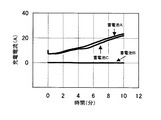
(試験条件)上記の蓄電池を2Aの電流で終止電圧1.7Vまで放電した後、さらに100Ωの抵抗を14日間接続して、蓄電池を深い放電状態とした。この後、抵抗を取り外した蓄電池を0℃の環境下で16時間放置した後に、2.4V(制限電流50A)の定電圧充電を10分間行い、このときの充電電流の変化を観察した。
(試験結果)試験結果を図1に示す。
【0020】
純鉛を用いた蓄電池Bでは、10分間の充電中、充電電流は0Aで推移し、ほとんど充電されず、充電受け入れ特性は悪かった。一方、本発明品の蓄電池Aおよび鉛―スズ合金のみを用いた蓄電池Cは、充電電流が流れ、充電受け入れ特性は良好であった。
【0021】
この試験結果から、深放電後の充電特性の改善には、正極格子体中のスズの存在が有効であることがわかる。特に、本発明の蓄電池Aの正極格子体は、蓄電池Cに比べてスズ含有量が少ないが、スズが正極活物質と接触する部分に集中的に存在するため、そのスズの存在がより効果的に作用したといえる。
[トリクル(フロート)寿命試験]
(試験条件)上記の蓄電池を、環境温度60℃の気相中においてトリクル充電電圧2.275Vで常時充電し、1ヶ月毎に取り出して放電電流10A(終止電圧1.0V)で容量試験を行った。
(試験結果)試験結果を図2に示す。
【0022】
鉛―スズ合金のみを用いた蓄電池Cでは、5ヶ月目の容量が初期容量の50%を切ったが、蓄電池Aおよび純鉛を用いた蓄電池Bでは、10ヶ月目も初期容量の50%以上を維持していた。
【0023】
試験後、蓄電池を解体し、正極板を調査したところ、蓄電池Cでは合金格子体の特徴である粒界腐食がかなり進行していたが、蓄電池A、蓄電池Bでは格子体の粒界腐食はほとんど認められなかった。
【0024】
これらの試験結果から明らかなように、蓄電池Aの正極格子体は、純鉛(Pb:99.99質量%)板に鉛―10質量%スズ合金板を重ね合わせ、圧延加工することにより一体化したシートからなっているので、鉛―スズ合金のみを圧延したものと異なり、スズが、活物質が接する表面部に部分的に集中しており、他の部分では純鉛が多く存在するため、トリクル寿命における純鉛の効果が有効的に得られたものと考えられる。
[蓄電池D−1〜K−5]次に、蓄電池Aの構成において、純鉛シートに重ね合わせる鉛−スズ合金層の厚さおよび鉛−スズ合金に対するスズ含有量の適正な範囲について試験結果に基づいて説明する。
[鉛―スズ合金層の厚さおよびスズ含有量の蓄電池性能に及ぼす影響]
(試験条件)一体化されたシートの総厚さに対する鉛―スズ合金層の厚さの比率および鉛−スズ合金の重量当たりスズ含有量の影響を調べるために、鉛−スズ合金に対するスズ含有量を0.3質量%、0.5質量%、1質量%、10質量%、20質量%、25質量%、30質量%、40質量%、45質量%、50質量%を含有する鉛―スズ合金板を圧延加工して、厚さ0.03mm、0.05mm、0.11mm、0.42mm、2.5mm、4.3mm、6.7mmおよび8.2mmのシート材を作製した。そして、この鉛―スズ合金シート材と厚さ10mmの純鉛(Pb:99.99質量%)板を重ね合わせ、厚さ0.6mmになるまで圧延加工することにより、シート厚に対する鉛−スズ合金層の厚み比率および鉛−スズ合金層に対するスズ含有量の異なる純鉛板と鉛―スズ合金板とが一体化したシートを製作した。
【0025】
次に、これらのシートを打ち抜いて5mm×7mmの升目を持つ正極格子体を製作し、それらを正極板に用いて、29種類の蓄電池(蓄電池D−1〜蓄電池K−5)を製作した。これらの蓄電池では、正極格子体以外の構成は、蓄電池Aと同じとした。
【0026】
蓄電池D−1〜蓄電池K−5に用いた正極格子体のシート総厚さに対する鉛−スズ合金層の厚さ比率X(%)と、鉛−スズ合金層のSn含有量Y(質量%)を、表1および表2に示す。
【0027】
【表1】

これら29種類の蓄電池について、深放電後の充電受け入れ特性試験とトリクル寿命試験を行った。いずれの試験も、上述した蓄電池A、B、Cの比較試験を行った際と同じ条件である。
【0029】
試験結果を以下に示す。
【0030】
【表3】
表3および4において、深放電後の充電受け入れ特性試験とトリクル寿命試験の結果を以下の基準により評価した。すなわち、試験開始から試験終了までの間に充電電流が流れた(即ち、充電を受け入れることができる)場合を「良好」と判断した。
(深放電後の充電受け入れ特性試験結果)
○:充電受け入れ特性が良好であったもの
×:充電受け入れ特性が悪かったもの
(トリクル寿命試験結果)
○:トリクル寿命試験における10ヶ月目の放電容量が初期容量の50%以上のもの
×:トリクル寿命試験における10ヶ月目の放電容量が初期容量の50%未満のもの
次に、上記Xの値を横軸に、Yの値を縦軸にとった図3において、深放電後の充電受け入れ特性試験とトリクル寿命試験のいずれにおいても良好であったものを○印をもって示し、いずれか一方の試験で不良であったものに×印を付して示した。
【0032】
図3において、0.5≦X≦40で、かつ0.5≦Y≦−0.625X+50の領域に位置する鉛蓄電池が、トリクル寿命性能に優れ、しかも、良好な深放電後の充電受け入れ特性を示すことが明らかになった。
【0033】
さらに、上記のトリクル寿命試験の結果を、以下の基準により再評価した。
【0034】
○:トリクル寿命試験における10ヶ月目の放電容量が初期容量の70%以上のもの
×:トリクル寿命試験における10ヶ月目の放電容量が初期容量の70%未満のもの
その結果を表5および表6に示す。
【0035】
【表5】
この再評価結果に基づき、受け入れ特性試験とトリクル寿命試験のいずれにおいても良好であったものを○印を付し、いずれか一方の試験で不良であったものに×印を付して、図4に示した。
【0037】
図4において、0.5≦X≦30で、かつ0.5≦Y≦−0.625X+50の領域に位置する鉛蓄電池が、トリクル寿命性能に優れ、しかも、良好な深放電後の充電受け入れ特性を示すことが明らかになった。
【0038】
図3において、X<0.5およびY<0.5の領域においては、深放電後の充電受け入れ特性が悪くなっている。これは、これらの領域においては、鉛−スズ系合金層の厚さが薄いか、もしくは鉛−スズ系合金層中のスズ含有量が少ないため、純鉛正極格子体の欠点である深放電後の充電受け入れ特性の劣る点を十分解消し得なかったためと考えられる。
【0039】
また、X>50およびY>−0.625X+50の領域において、トリクル充電寿命特性が悪くなっている。これは、これらの領域においては、鉛−スズ系合金層の厚さや、スズ含有量が過大であり、粒界腐食が進行した結果、トリクル充電寿命に影響を与える正極格子体中に残存する導電経路(非腐食部分)が狭くなったためと考えられる。
【0040】
したがって、シートの総厚さに対する鉛−スズ系合金層の厚さの比率Xに関して言えば、トリクル寿命性能と深放電後の充電受け入れ特性のいずれをも改善するためには、0.5≦X≦40、より好ましくは0.5≦X≦30とするのが良い。また、同様の観点から、鉛−スズ系合金層の質量当たりのスズ含有量Yに関して言えば、0.5≦Y≦−0.625X+50とするのが良い。さらには、前記のXとYを、0.5≦X≦40(より好ましくは0.5≦X≦30)と0.5≦Y≦−0.625X+50で区画される領域内の値とするのが最も適正であると言える。
【0041】
以上のように、純鉛(99.99質量%以上)板に、鉛―スズ系合金板を重ね合わせ、圧延加工することにより一体化したシートから製作した格子体を正極板に用いることで、トリクル寿命性能が優れ、しかも、深放電後の充電受け入れ特性に問題の発生しない制御弁式鉛蓄電池を得ることができることがわかった。
【0042】
上記の実施形態では、鉛−スズ系合金として、スズを0.5〜50質量%含有する鉛−スズ合金を用いたが、スズの存在が深放電後の充電受け入れ特性の改善に寄与していることから、鉛−スズ−カルシウム合金などのスズと他の金属成分を含んでなる鉛合金を用いても良い。なお、このときのスズ含有量Y(質量%)も、合金層の厚さ比率をX(%)として、0.5≦Y≦−0.625X+50の関係を満たしておく必要がある。
【0043】
上記の実施形態では、円筒型制御弁式鉛蓄電池について本発明の有効性を述べてきたが、その効果は、制御弁式鉛蓄電池おいてのみ得られるのではなく、その効果が正極板に起因しているのであることから、流動液が存在する、いわゆる、開放型鉛蓄電池においても同様の正極板を用いることによって同じ効果が得られることは言うまでもない。
【0044】
また、上記の実施形態では、純鉛板からなる層に鉛−スズ系合金層を圧延加工により一体化させたが、純鉛板の表面に鉛−スズ系合金層を設ける方法としては、化学的蒸着法、物理的蒸着法、あるいは拡散浸透法、電気化学的メッキ法などを利用することができる。ただ、これらの方法の中では、圧延加工による方法が最も簡便で、低コストであり、量産性にも優れている。
【0045】
【発明の効果】
以上述べたように、純鉛(99.99%)板表面の少なくとも一方に、鉛―スズ合金板層を形成したシートを打ち抜き加工またはエキパンド加工で形成した格子体を正極板に用いることで、トリクル寿命性能が優れ、しかも深放電後の充電受け入れ性に問題のない鉛蓄電池を得ることができ、特に、シート厚みに対する鉛−スズ合金層の厚み比率をX(%)とし、鉛−スズ合金層に対するスズ含有量をY(質量%)とした時に、0.5≦X≦40、好ましくは0.5≦X≦30かつ0.5≦Y≦−0.625X+50を満足することによって上記効果がより一層顕著に得られ、その工業的価値は極めて大きい。
【図面の簡単な説明】
【図1】 深放電後の充電受け入れ特性試験
【図2】 トリクル(フロート)寿命試験
【図3】 一体化したシートの総厚みに対する鉛―スズ合金層の厚み比率および鉛―スズ合金層のスズ含有量(質量%)と蓄電池性能との関係
【図4】 図3の試験結果を蓄電池のトリクル寿命が良好である評価基準を高くして再評価した結果を示す図。[0001]
BACKGROUND OF THE INVENTION
The present invention relates to a lead-acid battery.
[0002]
[Prior art]
Applications of lead-acid batteries are divided into so-called trickle applications (float applications) in which charging is normally performed at a constant voltage and discharging is necessary, and so-called cycle applications in which discharging and charging are repeated. The cause of deterioration of the lead storage battery in the former trickle application is corrosion of the positive electrode grid. This is because the alloy used for the lattice material is formed at grain boundaries, and the grain boundaries are selectively corroded during charging. As a countermeasure, U.S. S. P. 3862861 proposes to use a lattice processed from a pure lead sheet.
[0003]
Pure lead does not cause the above-mentioned problems because the grain boundaries are not clear like lead alloys, and an excellent trickle life can be obtained. However, when pure lead is used for the lattice, there is a drawback that the capacity is not recovered even if it is charged in a cycle application, particularly when deep discharge is performed. As a countermeasure, a method using a grid obtained by punching or expanding a lead-tin alloy into a sheet by rolling instead of pure lead is disclosed in U.S. Pat. S. P. 5120620. This method improves the charge acceptance characteristics after deep discharge, but because it is a lead-tin alloy, grain boundaries exist, the corrosion of the positive grid progresses in the trickle life, and the life is shorter than that of a pure lead grid. There's a problem.
[0004]
[Problems to be solved by the invention]
The problem to be solved by the present invention is to provide a lead storage battery having excellent charge recovery after deep discharge, which is a drawback of the pure lead grid, while maintaining the excellent trickle life performance of the pure lead grid as described above. There is.
[0005]
[Means for Solving the Problems]
As a means to solve the problem, a grid formed by punching or expanding a sheet on which a lead-tin alloy layer is formed on at least one surface of a pure lead (99.99% or more) plate is used for a positive electrode plate. In the lead storage battery, the ratio of the lead-tin alloy layer to the total thickness of the sheet is X (%), and the tin content of the lead-tin alloy layer is Y (mass%). Satisfies the following formula, 0.5 ≦ X ≦ 40 and 0.5 ≦ Y ≦ −0.625X + 50 .
[0006]
The grid formed by stamping or expanding the sheet of pure lead shows excellent performance under the condition of continuous charging, but has the disadvantage of poor charge recovery characteristics when deep discharge occurs, The inventor of the present application has found that the charge recoverability does not deteriorate even when deep discharge is performed by forming a lead-tin alloy layer on at least one surface of the sheet.
[0007]
Further, the lead to the total thickness of the sheet - the X (%) Ratio of tin alloy layer, the lead - when the tin content of the tin-based alloy layer was Y (mass%), X, Y have the following formula 0.5 ≦ X ≦ 40 and 0.5 ≦ Y ≦ −0.625X + 50 .
[0008]
The inventor of the present application has found that the charge recovery characteristics after deep discharge can be improved by forming a lead-tin alloy layer on at least one surface of the pure lead sheet. As a result of producing and testing samples in which the thickness ratio of the integrated lead-tin alloy layer and the tin content relative to the lead-tin alloy were changed, the ratio of the lead-tin alloy layer to the sheet thickness was expressed as X ( %), When the tin content of the lead-tin alloy layer is Y (mass%), if 0.5 ≦ X ≦ 40 and 0.5 ≦ Y ≦ −0.625X + 50 are satisfied, It has been found that excellent charge recovery characteristics can be obtained with respect to deep discharge while having the effect of pure lead.
[0009]
DETAILED DESCRIPTION OF THE INVENTION
The present invention will be described in detail below based on examples.
[0010]
In this example, a cylindrical control valve type lead storage battery in which positive and negative electrode plates and a separator are wound in a spiral shape and inserted into a cylindrical battery case using the soft characteristic of a pure lead sheet will be described.
[Storage battery A] (product of the present invention)
An integrated sheet with a thickness of 0.6 mm is obtained by superimposing a 0.4 mm-thick lead-10 mass% tin alloy plate on a pure lead (99.99%) plate with a thickness of 10 mm and rolling it. Produced. By punching the sheet, a lattice body having a grid of 5 mm × 7 mm was manufactured.
[0011]
A positive electrode plate was manufactured by applying a paste obtained by adding dilute sulfuric acid to a mixed powder of t-PbO, Pb 3 O 4 , and metal Pb on the lattice body.
[0012]
The negative electrode plate is manufactured by using a grid made of pure lead (lead: 99.99% by mass) sheet and applying a paste obtained by adding dilute sulfuric acid to a mixed powder of t-PbO and metal Pb. did.
[0013]
The electrode plate thickness was 0.9 mm for both the positive and negative electrode plates.
[0014]
These positive / negative electrode plates and glass separators are combined, and a high compression force (about 100 kPa) is applied and wound into a spiral to form an element (a component in which the positive / negative electrode plates and the separator are superposed is called an element). The element was housed in a cylindrical container having a diameter of 49 mm and a height of 100 mm, and a cylindrical control valve type lead-acid battery having a discharge capacity (rated capacity) at a 5-hour rate of 10 Ah was manufactured.
[0015]
When the separator is pressed with a load of 20 kPa using a glass fiber having an average diameter of about 1 μm as a main component and having a thickness of about 0.9 mm and a porosity of about 91% mixed with 20% by mass of silica. The one having a thickness of 0.8 mm was used.
[0016]
As an electrolytic solution, one having a specific gravity of 1.24 (at 20 ° C.) in which 25 g / l of sodium sulfate was dissolved in dilute sulfuric acid was used. Here, battery case formation means formation performed by inserting an unformed element into the battery case and injecting an electrolytic solution.
[0017]
A storage battery manufactured by the above configuration and method is represented by A.
[0018]
In order to show the excellent characteristics of the storage battery A of one example according to the present invention, a comparative test with a conventional product was performed. The storage battery used for the comparison control in that case is shown concretely.
[Storage battery B] (Comparative example)
A grid body produced by rolling the pure lead (Pb: 99.99% by mass) plate from a 0.6 mm thick sheet by the same method as described above is used for the positive electrode plate, and other configurations are the same as those of the storage battery A. Thus, a storage battery B was produced.
[Storage battery C] (Comparative example)
A grid body manufactured by a method similar to the above from a 0.6 mm thick sheet obtained by rolling a 99.0% by mass lead-1.0% by mass tin alloy plate is used for the positive electrode plate, and other configurations are used for the storage battery. A storage battery C was produced in the same manner as A.
[0019]
The above three types of storage batteries were subjected to a comparative test of charge acceptance characteristics and trickle life after deep discharge. The results are shown below.
[Charge acceptance characteristics after deep discharge]
(Test conditions) After discharging the above storage battery with a current of 2 A to a final voltage of 1.7 V, a resistance of 100 Ω was further connected for 14 days to place the storage battery in a deep discharge state. Thereafter, the storage battery from which the resistance was removed was left in an environment of 0 ° C. for 16 hours, and then charged at a constant voltage of 2.4 V (limit current 50 A) for 10 minutes.
(Test results) The test results are shown in FIG.
[0020]
In the storage battery B using pure lead, the charging current changed at 0 A during the charging for 10 minutes, the battery was hardly charged, and the charge acceptance characteristics were poor. On the other hand, the storage battery A of the present invention and the storage battery C using only the lead-tin alloy flowed a charging current and had good charge acceptance characteristics.
[0021]
From this test result, it can be seen that the presence of tin in the positive electrode grid is effective in improving the charge characteristics after deep discharge. In particular, the positive electrode grid of the storage battery A of the present invention has a lower tin content than the storage battery C, but the presence of tin is more effective because the tin is concentrated in the portion where it contacts the positive electrode active material. It can be said that it acted on.
[Trickle (float) life test]
(Test conditions) The above storage battery is always charged at a trickle charge voltage of 2.275 V in a gas phase at an environmental temperature of 60 ° C., taken out every month, and subjected to a capacity test at a discharge current of 10 A (end voltage of 1.0 V). It was.
(Test results) The test results are shown in FIG.
[0022]
In storage battery C using only lead-tin alloy, the capacity at the fifth month fell below 50% of the initial capacity, but in storage battery A and storage battery B using pure lead, the capacity at the 10th month was also more than 50% of the initial capacity. Was maintained.
[0023]
After the test, the storage battery was disassembled and the positive electrode plate was examined. In the storage battery C, the intergranular corrosion characteristic of the alloy lattice body was considerably advanced, but in the storage battery A and storage battery B, the intergranular corrosion of the lattice body was almost complete. I was not able to admit.
[0024]
As is clear from these test results, the positive electrode grid of the storage battery A is integrated by superposing a lead-10 mass% tin alloy plate on a pure lead (Pb: 99.99 mass%) plate and rolling it. Unlike the rolled sheet of lead-tin alloy, tin is partially concentrated on the surface part where the active material is in contact, and there is a lot of pure lead in other parts. It is considered that the effect of pure lead on the trickle life was obtained effectively.
[Storage batteries D-1 to K-5] Next, in the configuration of the storage battery A, the thickness of the lead-tin alloy layer superimposed on the pure lead sheet and the proper range of the tin content with respect to the lead-tin alloy are shown in the test results. This will be explained based on.
[Effect of lead-tin alloy layer thickness and tin content on battery performance]
(Test conditions) In order to investigate the effect of the thickness of the lead-tin alloy layer on the total thickness of the integrated sheet and the tin content per weight of the lead-tin alloy, the tin content relative to the lead-tin alloy Lead-tin containing 0.3%, 0.5%, 1%, 10%, 20%, 25%, 30%, 40%, 45%, 50% by weight The alloy plate was rolled to produce sheet materials having thicknesses of 0.03 mm, 0.05 mm, 0.11 mm, 0.42 mm, 2.5 mm, 4.3 mm, 6.7 mm, and 8.2 mm. Then, this lead-tin alloy sheet material and a pure lead (Pb: 99.99 mass%) plate having a thickness of 10 mm are overlapped and rolled to a thickness of 0.6 mm, whereby lead-tin relative to the sheet thickness is obtained. A sheet in which a pure lead plate and a lead-tin alloy plate having different thickness ratios of the alloy layer and a tin content with respect to the lead-tin alloy layer were integrated was manufactured.
[0025]
Next, these sheets were punched to produce positive grids having a grid of 5 mm × 7 mm, and 29 types of storage batteries (storage batteries D-1 to K-5) were manufactured using them as positive electrode plates. In these storage batteries, the configuration other than the positive grid is the same as that of the storage battery A.
[0026]
The thickness ratio X (%) of the lead-tin alloy layer to the total sheet thickness of the positive electrode grid used in the storage batteries D-1 to K-5, and the Sn content Y (mass%) of the lead-tin alloy layer Are shown in Table 1 and Table 2.
[0027]
[Table 1]
These 29 kinds of storage batteries were subjected to charge acceptance characteristics test and trickle life test after deep discharge. All the tests are under the same conditions as when the above-described comparative tests of the storage batteries A, B, and C were performed.
[0029]
The test results are shown below.
[0030]
[Table 3]
In Tables 3 and 4, the results of the charge acceptance characteristic test and trickle life test after deep discharge were evaluated according to the following criteria. That is, the case where the charging current flowed from the start of the test to the end of the test (that is, the charging can be accepted) was judged as “good”.
(Charge acceptance characteristics test result after deep discharge)
○: Good charge acceptance characteristics ×: Bad charge acceptance characteristics (Trickle life test results)
○: The discharge capacity at the 10th month in the trickle life test is 50% or more of the initial capacity. X: The discharge capacity at the 10th month in the trickle life test is less than 50% of the initial capacity. In FIG. 3, in which the horizontal axis represents the Y value, the good mark in both the charge acceptance characteristic test after deep discharge and the trickle life test is indicated by a circle. In either one of the tests, Those that were defective were marked with a cross.
[0032]
In FIG. 3, the lead-acid battery located in the region of 0.5 ≦ X ≦ 40 and 0.5 ≦ Y ≦ −0.625X + 50 has excellent trickle life performance and good charge acceptance characteristics after deep discharge. It became clear to show.
[0033]
Furthermore, the above-mentioned trickle life test results were re-evaluated according to the following criteria.
[0034]
○: The discharge capacity at the 10th month in the trickle life test is 70% or more of the initial capacity ×: The discharge capacity at the 10th month in the trickle life test is less than 70% of the initial capacity The results are shown in Tables 5 and 6 Shown in
[0035]
[Table 5]
Based on the results of this re-evaluation, those that were good in both the acceptance characteristics test and the trickle life test were marked with a circle, and those that were defective in either test were marked with a cross. This is shown in FIG.
[0037]
In FIG. 4, the lead storage battery located in the region of 0.5 ≦ X ≦ 30 and 0.5 ≦ Y ≦ −0.625X + 50 has excellent trickle life performance and good charge acceptance characteristics after deep discharge. It became clear to show.
[0038]
In FIG. 3, in the region of X <0.5 and Y <0.5, the charge acceptance characteristics after deep discharge are deteriorated. This is because, in these regions, the lead-tin alloy layer is thin or the tin content in the lead-tin alloy layer is small, so that after the deep discharge, which is a drawback of the pure lead cathode grid This is thought to be because the inferior point of the charge acceptance characteristics of the battery could not be solved sufficiently.
[0039]
In addition, trickle charge life characteristics are deteriorated in the region of X> 50 and Y> −0.625X + 50 . This is because, in these regions, the thickness of the lead-tin-based alloy layer and the tin content are excessive, and as a result of the progress of intergranular corrosion, the remaining conductive material in the positive electrode grid that affects the trickle charge life. This is probably because the path (non-corrosive part) has become narrower.
[0040]
Accordingly, in terms of the ratio X of the thickness of the lead-tin alloy layer to the total thickness of the sheet, in order to improve both trickle life performance and charge acceptance characteristics after deep discharge, 0.5 ≦ X ≦ 40, more preferably 0.5 ≦ X ≦ 30. From the same point of view, in terms of the tin content Y per mass of the lead-tin alloy layer, 0.5 ≦ Y ≦ −0.625X + 50 is preferable. Furthermore, the above X and Y are set to values within a region defined by 0.5 ≦ X ≦ 40 (more preferably 0.5 ≦ X ≦ 30) and 0.5 ≦ Y ≦ −0.625X + 50. Is the most appropriate.
[0041]
As described above, by using a grid body manufactured from a sheet integrated with a pure lead (99.99 mass% or more) plate by superimposing a lead-tin-based alloy plate and rolling the positive plate, It was found that a control valve type lead storage battery having excellent trickle life performance and having no problem in charge acceptance characteristics after deep discharge can be obtained.
[0042]
In the above embodiment, a lead-tin alloy containing 0.5 to 50% by mass of tin is used as the lead-tin alloy, but the presence of tin contributes to the improvement of charge acceptance characteristics after deep discharge. Therefore, a lead alloy containing tin and other metal components such as a lead-tin-calcium alloy may be used. The tin content Y (mass%) at this time also needs to satisfy the relationship of 0.5 ≦ Y ≦ −0.625X + 50 , where the thickness ratio of the alloy layer is X (%).
[0043]
In the above embodiment, the effectiveness of the present invention has been described for a cylindrical control valve type lead acid battery, but the effect is not obtained only in the control valve type lead acid battery, but the effect is attributed to the positive electrode plate. Therefore, it goes without saying that the same effect can be obtained by using a similar positive electrode plate in a so-called open lead-acid battery in which a fluid is present.
[0044]
In the above embodiment, the lead-tin alloy layer is integrated with the layer made of the pure lead plate by rolling. However, as a method of providing the lead-tin alloy layer on the surface of the pure lead plate, A vapor deposition method, a physical vapor deposition method, a diffusion penetration method, an electrochemical plating method, or the like can be used. However, among these methods, the rolling method is the simplest, low cost, and excellent in mass productivity.
[0045]
【The invention's effect】
As described above, by using a grid body formed by punching or expanding a sheet formed with a lead-tin alloy plate layer on at least one of pure lead (99.99%) plate surfaces as a positive electrode plate, A lead-acid battery with excellent trickle life performance and no problem in charge acceptability after deep discharge can be obtained. In particular, the thickness ratio of the lead-tin alloy layer to the sheet thickness is X (%), and the lead-tin alloy is obtained. The above effect is achieved by satisfying 0.5 ≦ X ≦ 40, preferably 0.5 ≦ X ≦ 30 and 0.5 ≦ Y ≦ −0.625X + 50 when the tin content with respect to the layer is Y (mass%). Is obtained more remarkably, and its industrial value is extremely large.
[Brief description of the drawings]
[Fig. 1] Charge acceptance characteristics test after deep discharge [Fig. 2] Trickle (float) life test [Fig. 3] Thickness ratio of lead-tin alloy layer to total thickness of integrated sheet and tin of lead-tin alloy layer Relationship between content (mass%) and storage battery performance FIG. 4 is a diagram showing a result of re-evaluation of the test result of FIG. 3 with a higher evaluation criterion that the trickle life of the storage battery is good.
Claims (1)
Priority Applications (1)
| Application Number | Priority Date | Filing Date | Title |
|---|---|---|---|
| JP2002323205A JP4678117B2 (en) | 2001-11-06 | 2002-11-06 | Lead acid battery |
Applications Claiming Priority (3)
| Application Number | Priority Date | Filing Date | Title |
|---|---|---|---|
| JP2001-341179 | 2001-11-06 | ||
| JP2001341179 | 2001-11-06 | ||
| JP2002323205A JP4678117B2 (en) | 2001-11-06 | 2002-11-06 | Lead acid battery |
Publications (3)
| Publication Number | Publication Date |
|---|---|
| JP2003208898A JP2003208898A (en) | 2003-07-25 |
| JP2003208898A5 JP2003208898A5 (en) | 2005-12-15 |
| JP4678117B2 true JP4678117B2 (en) | 2011-04-27 |
Family
ID=27666947
Family Applications (1)
| Application Number | Title | Priority Date | Filing Date |
|---|---|---|---|
| JP2002323205A Expired - Fee Related JP4678117B2 (en) | 2001-11-06 | 2002-11-06 | Lead acid battery |
Country Status (1)
| Country | Link |
|---|---|
| JP (1) | JP4678117B2 (en) |
Families Citing this family (2)
| Publication number | Priority date | Publication date | Assignee | Title |
|---|---|---|---|---|
| DE102005038064A1 (en) * | 2005-08-10 | 2007-02-15 | Deutsche Exide Gmbh | electrode grid |
| JP2017068953A (en) * | 2015-09-29 | 2017-04-06 | 株式会社Gsユアサ | Punching current collector for lead-acid storage battery, method of manufacturing the same and lead-acid storage battery |
Citations (7)
| Publication number | Priority date | Publication date | Assignee | Title |
|---|---|---|---|---|
| JPS61124064A (en) * | 1984-11-20 | 1986-06-11 | Matsushita Electric Ind Co Ltd | Grid body for lead storage battery and its manufacture |
| JPS6386352A (en) * | 1986-09-30 | 1988-04-16 | Shin Kobe Electric Mach Co Ltd | Lead acid battery |
| JPH0355757A (en) * | 1989-03-29 | 1991-03-11 | Aisin Seiki Co Ltd | Lead storage battery |
| JPH0574464A (en) * | 1991-09-12 | 1993-03-26 | Matsushita Electric Ind Co Ltd | Sealed lead-acid storage battery |
| JPH1154126A (en) * | 1997-08-04 | 1999-02-26 | Japan Storage Battery Co Ltd | Lattice for lead-acid battery |
| WO2001004976A1 (en) * | 1999-07-09 | 2001-01-18 | Japan Storage Battery Co., Ltd. | Positive plate current collector for lead storage battery and lead storage battery comprising the same |
| JP2001023646A (en) * | 1999-07-13 | 2001-01-26 | Japan Storage Battery Co Ltd | Manufacture of lead alloy rolled sheet for lead-acid battery grid |
-
2002
- 2002-11-06 JP JP2002323205A patent/JP4678117B2/en not_active Expired - Fee Related
Patent Citations (7)
| Publication number | Priority date | Publication date | Assignee | Title |
|---|---|---|---|---|
| JPS61124064A (en) * | 1984-11-20 | 1986-06-11 | Matsushita Electric Ind Co Ltd | Grid body for lead storage battery and its manufacture |
| JPS6386352A (en) * | 1986-09-30 | 1988-04-16 | Shin Kobe Electric Mach Co Ltd | Lead acid battery |
| JPH0355757A (en) * | 1989-03-29 | 1991-03-11 | Aisin Seiki Co Ltd | Lead storage battery |
| JPH0574464A (en) * | 1991-09-12 | 1993-03-26 | Matsushita Electric Ind Co Ltd | Sealed lead-acid storage battery |
| JPH1154126A (en) * | 1997-08-04 | 1999-02-26 | Japan Storage Battery Co Ltd | Lattice for lead-acid battery |
| WO2001004976A1 (en) * | 1999-07-09 | 2001-01-18 | Japan Storage Battery Co., Ltd. | Positive plate current collector for lead storage battery and lead storage battery comprising the same |
| JP2001023646A (en) * | 1999-07-13 | 2001-01-26 | Japan Storage Battery Co Ltd | Manufacture of lead alloy rolled sheet for lead-acid battery grid |
Also Published As
| Publication number | Publication date |
|---|---|
| JP2003208898A (en) | 2003-07-25 |
Similar Documents
| Publication | Publication Date | Title |
|---|---|---|
| US6037081A (en) | Expanded grid for electrode plate of lead-acid battery | |
| WO2010032782A1 (en) | Lead acid storage battery | |
| JP5061451B2 (en) | Anode current collector for lead acid battery | |
| JP4501330B2 (en) | Lead acid battery | |
| JP2004349197A (en) | Lead-base alloy for lead storage battery and lead storage battery using it | |
| WO2006049295A1 (en) | Negative electrode current collector for lead storage battery and lead storage battery including the same | |
| JP5656068B2 (en) | Liquid lead-acid battery | |
| US7223499B2 (en) | Lead battery | |
| JP4678117B2 (en) | Lead acid battery | |
| JP2006114417A (en) | Lead-acid storage battery | |
| WO2001004976A1 (en) | Positive plate current collector for lead storage battery and lead storage battery comprising the same | |
| JP5145644B2 (en) | Lead acid battery | |
| JP3091167B2 (en) | Lead storage battery | |
| JP2019207786A (en) | Lead acid battery | |
| JP2005122922A (en) | Manufacturing method of grid for lead acid battery and lead acid battery | |
| JP4374626B2 (en) | Lead acid battery | |
| JPH10321236A (en) | Lead-acid battery | |
| JP2011159551A (en) | Lead-acid storage battery | |
| JP5135692B2 (en) | Lead acid battery | |
| JP4896392B2 (en) | Lead acid battery | |
| JP2004186013A (en) | Electrode collector, its manufacturing method and sealed lead-acid battery | |
| JP2004079198A (en) | Lead accumulator | |
| JPH0574464A (en) | Sealed lead-acid storage battery | |
| JPH10294113A (en) | Positive electrode plate for sealed lead-acid battery | |
| JP3163509B2 (en) | Manufacturing method of hybrid bipolar plate |
Legal Events
| Date | Code | Title | Description |
|---|---|---|---|
| A521 | Request for written amendment filed |
Free format text: JAPANESE INTERMEDIATE CODE: A523 Effective date: 20051025 |
|
| A621 | Written request for application examination |
Free format text: JAPANESE INTERMEDIATE CODE: A621 Effective date: 20051025 |
|
| A711 | Notification of change in applicant |
Free format text: JAPANESE INTERMEDIATE CODE: A712 Effective date: 20051213 |
|
| A977 | Report on retrieval |
Free format text: JAPANESE INTERMEDIATE CODE: A971007 Effective date: 20080327 |
|
| A131 | Notification of reasons for refusal |
Free format text: JAPANESE INTERMEDIATE CODE: A131 Effective date: 20090220 |
|
| A521 | Request for written amendment filed |
Free format text: JAPANESE INTERMEDIATE CODE: A523 Effective date: 20090416 |
|
| A131 | Notification of reasons for refusal |
Free format text: JAPANESE INTERMEDIATE CODE: A131 Effective date: 20091124 |
|
| A521 | Request for written amendment filed |
Free format text: JAPANESE INTERMEDIATE CODE: A523 Effective date: 20100113 |
|
| A521 | Request for written amendment filed |
Free format text: JAPANESE INTERMEDIATE CODE: A523 Effective date: 20100113 |
|
| A711 | Notification of change in applicant |
Free format text: JAPANESE INTERMEDIATE CODE: A712 Effective date: 20100507 |
|
| A131 | Notification of reasons for refusal |
Free format text: JAPANESE INTERMEDIATE CODE: A131 Effective date: 20100608 |
|
| A521 | Request for written amendment filed |
Free format text: JAPANESE INTERMEDIATE CODE: A523 Effective date: 20100726 |
|
| TRDD | Decision of grant or rejection written | ||
| A01 | Written decision to grant a patent or to grant a registration (utility model) |
Free format text: JAPANESE INTERMEDIATE CODE: A01 Effective date: 20110105 |
|
| A01 | Written decision to grant a patent or to grant a registration (utility model) |
Free format text: JAPANESE INTERMEDIATE CODE: A01 |
|
| A61 | First payment of annual fees (during grant procedure) |
Free format text: JAPANESE INTERMEDIATE CODE: A61 Effective date: 20110118 |
|
| R150 | Certificate of patent or registration of utility model |
Free format text: JAPANESE INTERMEDIATE CODE: R150 Ref document number: 4678117 Country of ref document: JP Free format text: JAPANESE INTERMEDIATE CODE: R150 |
|
| FPAY | Renewal fee payment (event date is renewal date of database) |
Free format text: PAYMENT UNTIL: 20140210 Year of fee payment: 3 |
|
| LAPS | Cancellation because of no payment of annual fees |