JP4673562B2 - Motorcycle storage box and fuel tank structure - Google Patents
Motorcycle storage box and fuel tank structureInfo
- Publication number
- JP4673562B2 JP4673562B2 JP2004056735A JP2004056735A JP4673562B2 JP 4673562 B2 JP4673562 B2 JP 4673562B2 JP 2004056735 A JP2004056735 A JP 2004056735A JP 2004056735 A JP2004056735 A JP 2004056735A JP 4673562 B2 JP4673562 B2 JP 4673562B2
- Authority
- JP
- Japan
- Prior art keywords
- fuel tank
- fuel
- storage box
- motorcycle
- fuel pump
- Prior art date
- Legal status (The legal status is an assumption and is not a legal conclusion. Google has not performed a legal analysis and makes no representation as to the accuracy of the status listed.)
- Expired - Lifetime
Links
- 239000002828 fuel tank Substances 0.000 title claims description 97
- 239000000446 fuel Substances 0.000 claims description 126
- 239000000945 filler Substances 0.000 claims description 16
- 230000005540 biological transmission Effects 0.000 description 2
- 238000002347 injection Methods 0.000 description 2
- 239000007924 injection Substances 0.000 description 2
- 230000007423 decrease Effects 0.000 description 1
- 230000001681 protective effect Effects 0.000 description 1
- 239000011347 resin Substances 0.000 description 1
- 229920005989 resin Polymers 0.000 description 1
Images


Classifications
-
- B—PERFORMING OPERATIONS; TRANSPORTING
- B62—LAND VEHICLES FOR TRAVELLING OTHERWISE THAN ON RAILS
- B62J—CYCLE SADDLES OR SEATS; AUXILIARY DEVICES OR ACCESSORIES SPECIALLY ADAPTED TO CYCLES AND NOT OTHERWISE PROVIDED FOR, e.g. ARTICLE CARRIERS OR CYCLE PROTECTORS
- B62J35/00—Fuel tanks specially adapted for motorcycles or engine-assisted cycles; Arrangements thereof
-
- B—PERFORMING OPERATIONS; TRANSPORTING
- B62—LAND VEHICLES FOR TRAVELLING OTHERWISE THAN ON RAILS
- B62J—CYCLE SADDLES OR SEATS; AUXILIARY DEVICES OR ACCESSORIES SPECIALLY ADAPTED TO CYCLES AND NOT OTHERWISE PROVIDED FOR, e.g. ARTICLE CARRIERS OR CYCLE PROTECTORS
- B62J9/00—Containers specially adapted for cycles, e.g. panniers or saddle bags
Description
本発明は、自動二輪車の収納ボックス及び燃料タンク構造に関するものである。 The present invention relates to a motorcycle storage box and a fuel tank structure.
従来の自動二輪車の収納ボックス及び燃料タンク構造として、車体フレームに収納ボックス及びこの収納ボックスの後方に配置した燃料タンクを取付けたものが知られている(例えば、特許文献1参照。)。
特許文献1には、同公報の図3に示される通り、二輪車の車体フレーム1(符号については、同公報に記載されているものをそのまま使用した。)に、収納ボックス14と、この収納ボックス14の後方に配置した燃料タンク15とを取付け、収納ボックス14の後部に一体に設けた補機カバー25で燃料タンク15の上方を覆ったことが示されている。なお、22は収納ボックス14及び燃料タンク15の上方に開閉自在に設けたシートである。
In Patent Document 1, as shown in FIG. 3 of the publication, a
また、特許文献1には、同公報の図8に示される通り、収納ボックス14の後部に燃料タンクの上方のほぼ全体を覆う補機カバー25を一体に設けたことを示す。なお、23はシートを開閉自在に取付けるために収納ボックス14の前部に設けたヒンジ、32はシートの後部に設けたストライカ(不図示)を貫通させるために補機カバー25の前部に開けた貫通孔、27は燃料タンク15の給油口を塞ぐキャップを外部に突出させるキャップ孔である。
Further, in Patent Document 1, as shown in FIG. 8 of the same publication, it is shown that an auxiliary cover 25 that covers substantially the entire upper portion of the fuel tank is integrally provided at the rear portion of the
補機カバー25は、燃料タンク15の上方のほぼ全体を覆うものであるから、その面積は大きくなり、収納ボックス14及び補機カバー25は全体として大型で重くなる。
また、ストライカを貫通させる貫通孔32及びキャップを突出させるキャップ孔27を開けるため、補機カバー25の形状が複雑になる。
Since the auxiliary machine cover 25 covers almost the entire upper part of the fuel tank 15, the area of the auxiliary machine cover 25 becomes large, and the
Further, since the
更に、燃料タンク15が、例えば、タンク内蔵型の燃料ポンプを備える場合、燃料ポンプの燃料タンク15への取付部が外部に突出する(燃料ホースの接続部、燃料ポンプに通電するためのコネクタ等)ことがあり、この部分を保護することも望まれる。 Further, when the fuel tank 15 includes, for example, a tank built-in type fuel pump, a mounting portion of the fuel pump to the fuel tank 15 protrudes outside (a connection portion of the fuel hose, a connector for energizing the fuel pump, etc.) It is also desirable to protect this part.
本発明の課題は、自動二輪車の収納ボックス及び燃料タンク構造において、収納ボックスの小型・軽量化及び形状の簡素化を図るとともに、燃料ポンプの外部突出部を保護することにある。 SUMMARY OF THE INVENTION An object of the present invention is to reduce the size and weight of a storage box and simplify the shape of a storage box and a fuel tank structure for a motorcycle, and to protect an external protrusion of a fuel pump.
請求項1に係る発明は、シート下方に収納ボックスと燃料タンクとを設け、収納ボックスと隣り合うように燃料タンクを配置し、シートが収納ボックスと燃料タンクとの全体を上方から覆うようにし、燃料タンクの上面に給油口を設けるとともに、上面に設けた取付面に燃料ポンプを取付けた自動二輪車において、燃料ポンプの上方を収納ボックスから一体に延ばした庇部で覆い、且つ庇部を給油口まで延出しないようにし、庇部の左右端部にそれぞれ下方に折り曲げた折り曲げ部を形成し、燃料タンクの上面に設けられた取付面に取付けられた燃料ポンプの上端部から燃料の吐出口とコネクタとが突出し、吐出口をコネクタよりも収納ボックス寄りに配置したことを特徴とする。 The invention according to claim 1 is provided with a storage box and a fuel tank below the seat, the fuel tank is arranged adjacent to the storage box, and the seat covers the entirety of the storage box and the fuel tank from above, In a motorcycle in which a fuel filler is provided on the upper surface of the fuel tank and a fuel pump is mounted on the mounting surface provided on the upper surface, the upper part of the fuel pump is covered with a flange extending integrally from the storage box, and the flange is filled with the fuel filler. The fuel discharge port is formed from the upper end portion of the fuel pump attached to the mounting surface provided on the upper surface of the fuel tank. The connector protrudes, and the discharge port is arranged closer to the storage box than the connector .
燃料ポンプの上方を、収納ボックスの後部から後方に延ばした庇部で覆うようにしたことで、燃料ポンプを外部に露出させることがない。庇部は燃料ポンプの上方のみを覆うから、庇部を一体に設けた収納ボックスが小型・軽量になり、また、従来のようなストライカを通す孔やキャップを突出させる孔を設ける必要がない。更に、燃料ポンプの燃料タンクへの取付部が外部に突出しても、この突出部を庇部で保護することができる。 Since the upper portion of the fuel pump is covered with the flange extending rearward from the rear portion of the storage box, the fuel pump is not exposed to the outside. Since the collar portion covers only the upper part of the fuel pump, the storage box provided with the collar portion integrally becomes smaller and lighter, and there is no need to provide a hole for allowing the striker to pass through or a hole for projecting the cap as in the prior art. Furthermore, even if the mounting portion of the fuel pump to the fuel tank protrudes to the outside, this protruding portion can be protected by the flange portion.
請求項2に係る発明は、燃料ポンプの取付面を、燃料ポンプの上面よりも一段低くしたことを特徴とする。
燃料ポンプの取付面を、燃料タンクの上面よりも一段低くしたことで、庇部を特に高く形成することがなく、また、燃料ポンプの外部への突出部をその周囲よりも低くできる。
The invention according to claim 2 is characterized in that the mounting surface of the fuel pump is made one step lower than the upper surface of the fuel pump.
By making the mounting surface of the fuel pump one step lower than the upper surface of the fuel tank, the flange portion is not particularly formed high, and the protruding portion to the outside of the fuel pump can be made lower than its surroundings.
請求項3に係る発明は、燃料ポンプの取付面を給油口より低い位置に形成することを特徴とする。 The invention according to claim 3 is characterized in that the mounting surface of the fuel pump is formed at a position lower than the fuel filler opening.
請求項4に係る発明は、燃料ポンプを、車体センタに対してオフセットすることを特徴とする。
車体センタに対してオフセットした燃料ポンプの上方のみを庇部で覆ことが可能になる。
The invention according to claim 4 is characterized in that the fuel pump is offset with respect to the vehicle body center.
Only the upper part of the fuel pump offset with respect to the vehicle body center can be covered with the flange.
請求項5に係る発明は、燃料ポンプを、エアクリーナ側にオフセットすることを特徴とする。
燃料ポンプをエンジンの吸気系に近接させることが可能になる。サイドスタンドがある場合は、エアクリーナ側はサイドスタンド側であり、車体が傾く側に燃料ポンプを配置することが可能になる。
The invention according to
The fuel pump can be brought close to the intake system of the engine. When there is a side stand, the air cleaner side is the side stand side, and the fuel pump can be arranged on the side where the vehicle body is inclined .
請求項6に係る発明は、燃料ポンプの上部の突出部を周囲より低くしたことを特徴とする。
燃料ポンプの突出部が低い位置にあるため、突出部を保護することができる。
The invention according to claim 6 is characterized in that the upper projecting portion of the fuel pump is made lower than the surroundings.
Since the protrusion of the fuel pump is at a low position, the protrusion can be protected.
請求項7に係る発明は、燃料ポンプの吐出口から燃料タンクと収納ボックスとの間を通り、吸気マニホールドの吸い込み口に接続する燃料ホースを備えることを特徴とする。 The invention according to claim 7 is characterized by comprising a fuel hose that passes between the fuel tank and the storage box from the discharge port of the fuel pump and is connected to the suction port of the intake manifold.
請求項8に係る発明は、燃料タンクが、側面視で後上方へ延びるフランジを備え、このフランジの後部がリヤフレームに沿うように配置されてリヤフレームに固定されることを特徴とする。 The invention according to claim 8 is characterized in that the fuel tank includes a flange extending rearward and upward in a side view, and a rear portion of the flange is disposed along the rear frame and fixed to the rear frame.
請求項10に係る発明は、取付面の側方に、この取付面よりも一段高い燃料タンクの上面が配置され、庇部が、燃料ポンプの上方を覆うとともに、取付面の側方に配置された燃料タンクの上面も覆うことを特徴とする。In the invention according to
請求項11に係る発明は、燃料タンクが、リヤフレームに支持され、このリヤフレームにシートの底板を支持するシート支持バーが燃料タンクの上面を横切るようにして取付けられていることを特徴とする。The invention according to
請求項1に係る発明では、燃料ポンプの上方を収納ボックスの後部から後方に延ばした庇部で覆うようにしたので、庇部で燃料ポンプの上方のみを覆えばよいから、庇部を一体に設けた収納ボックスを小型・軽量にすることができる。 In the invention according to claim 1, since the upper part of the fuel pump is covered with the hook part extending rearward from the rear part of the storage box, it is only necessary to cover the upper part of the fuel pump with the hook part. The provided storage box can be made smaller and lighter.
また、庇部に、従来のようなストライカを通す孔やキャップを突出させる孔を設ける必要がないため、庇部の形状を簡素にすることができる。更に、燃料ポンプの燃料タンクへの取付部が外部に突出しても、この突出部を庇部で確実に保護することができ、自動二輪車の信頼性を高めることができる。 Moreover, since it is not necessary to provide the hole which lets a striker pass, and the hole which makes a cap protrude in the collar part, the shape of a collar part can be simplified. Further, even if the attachment portion of the fuel pump to the fuel tank protrudes to the outside, the protrusion portion can be reliably protected by the flange portion, and the reliability of the motorcycle can be improved.
請求項2に係る発明では、燃料ポンプの取付面を、燃料タンクの上面よりも一段低くしたので、庇部を燃料タンクよりも特に高く形成することがなく、ほぼ平坦な形状にすることができ、収納ボックスの形状の簡素化を図ることができて、収納ボックスのコストを下げることができる。また、燃料ポンプの外部への突出部が低い位置にあるため、突出部をより一層確実に保護することができる。 In the invention according to claim 2, since the mounting surface of the fuel pump is made one step lower than the upper surface of the fuel tank, the flange portion is not formed to be particularly higher than the fuel tank, and can be formed into a substantially flat shape. The shape of the storage box can be simplified, and the cost of the storage box can be reduced. Moreover, since the protrusion part to the exterior of a fuel pump exists in a low position, a protrusion part can be protected still more reliably.
請求項3に係る発明では、燃料ポンプの取付面を給油口より低い位置に形成する。 In the invention which concerns on Claim 3, the attachment surface of a fuel pump is formed in the position lower than a fuel filler opening.
請求項4に係る発明では、燃料ポンプを、車体センタに対してオフセットしたので、車体センタに対してオフセットした燃料ポンプの上方のみを庇部で覆えば、庇部を小さく設定することもできる。 In the invention according to claim 4, since the fuel pump is offset with respect to the vehicle body center, if only the upper part of the fuel pump offset with respect to the vehicle body center is covered with the flange, the flange can be set small.
請求項5に係る発明では、燃料ポンプを、エアクリーナ側にオフセットしたので、燃料ポンプをエンジンの吸気系に近接させることができ、燃料配管を短くすることができる。また、エアクリーナ側はサイドスタンド側であり、車体が傾くため、燃料タンク内の燃料が少ないときでも、吸気系に燃料を良好に供給できる。
In the invention according to
請求項6に係る発明では、燃料ポンプの上部の突出部を周囲より低くしたので、突出部を保護することができる。 In the invention which concerns on Claim 6 , since the protrusion part of the upper part of a fuel pump was made lower than the circumference | surroundings, a protrusion part can be protected.
請求項7に係る発明では、燃料ポンプの吐出口から燃料タンクと収納ボックスとの間を通り、吸気マニホールドの吸い込み口に接続する燃料ホースを備える。 In the invention which concerns on Claim 7 , it has a fuel hose which passes between a fuel tank and a storage box from the discharge port of a fuel pump, and is connected to the suction port of an intake manifold.
請求項8に係る発明では、燃料タンクが、側面視で後上方へ延びるフランジを備え、このフランジの後部がリヤフレームに沿うように配置されてリヤフレームに固定される。 In the invention according to claim 8 , the fuel tank includes a flange extending rearward and upward in a side view, and a rear portion of the flange is disposed along the rear frame and fixed to the rear frame.
請求項9に係る発明では、取付面の側方に、この取付面よりも一段高い燃料タンクの上面が配置され、庇部が、燃料ポンプの上方を覆うとともに、取付面の側方に配置された燃料タンクの上面も覆う。 In the invention according to claim 9, the upper surface of the fuel tank that is one step higher than the mounting surface is disposed on the side of the mounting surface, and the flange portion is disposed on the side of the mounting surface while covering the upper side of the fuel pump. Cover the upper surface of the fuel tank.
請求項10に係る発明では、燃料タンクが、リヤフレームに支持され、このリヤフレームにシートの底板を支持するシート支持バーが燃料タンクの上面を横切るようにして取付けられている。
In the invention according to
本発明を実施するための最良の形態を添付図に基づいて以下に説明する。なお、図面は符号の向きに見るものとする。
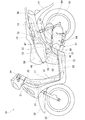
図1は本発明に係る自動二輪車の側面図であり、自動二輪車10は、車体フレーム11の後部にリヤフレーム12を備え、このリヤフレーム12に収納ボックス13及びこの収納ボックス13の後方に配置した燃料タンク14を取付け、これらの収納ボックス13及び燃料タンク14の上方を開閉式のシート16で覆った車両である。
The best mode for carrying out the present invention will be described below with reference to the accompanying drawings. The drawings are viewed in the direction of the reference numerals.
FIG. 1 is a side view of a motorcycle according to the present invention. A
車体フレーム11は、前端に設けたヘッドパイプ21と、このヘッドパイプ21から後方斜め下方に延ばしたダウンフレーム22と、このダウンフレーム22の下端部から後方そして上方へ延ばした左右一対のロアフレーム23,24(手前側の符号23のみ示す。)と、これらのロアフレーム23,24の後端のそれぞれに取付けた前述のリヤフレーム12とからなる。
The
ここで、31はヘッドパイプ21にステアリングシャフト32を介して操舵自在に取付けたフロントフォーク、33はフロントフォーク31の下端に回転自在に取付けた前輪、34はステアリングシャフト32の上部に取付けたハンドル、36は前輪33の上方を覆うフロントフェンダ、37,38(手前側の符号37のみ示す。)はロアフレーム23,24とリヤフレーム12とにそれぞれ取付けた左右一対のエンジンハンガプレート、41はエンジンハンガプレート37,38にリンク42を介してスイング自在に取付けたパワーユニット、43はパワーユニット41の後部とリヤフレーム12とに渡して取付けたリヤクッションユニットである。
Here, 31 is a front fork that is attached to the
また、44はエアクリーナ、46はエアクリーナ44にコネクティングチューブ47を介して接続したスロットルボディ、48はスロットルボディ46に接続するとともにパワーユニット41を構成するエンジン51のシリンダヘッド52に取付けた吸気マニホールド、53は吸気マニホールド48に取付けた燃料噴射弁、54はパワーユニット41を構成する無段変速機、56は無段変速機54の出力側に取付けた後輪、57は後輪56の上方を覆うリヤフェンダ、58は収納ボックス13に収納したヘルメットである。
Also, 44 is an air cleaner, 46 is a throttle body connected to the
図2は本発明に係る自動二輪車の後部を示す要部側面図(図中の矢印(FRONT)は車両前方を表す。以下同じ。)であり、樹脂製の収納ボックス13(ここでは、形状の理解を容易にするために輪郭を太線で示した。)の後部に一体に庇部71を設け、この庇部71で燃料タンク14の前部に設けた燃料ポンプ72の上方を覆ったことを示す。
収納ボックス13は、収納のために凹部73aを設けた収納部73と、この収納部73の上部と連続するように後方へ延ばした前述の庇部71とからなる。なお、13aはシート16を開閉自在に支持するために収納ボックス13の前壁に設けたシート支持部である。
FIG. 2 is a side view of the main part showing the rear part of the motorcycle according to the present invention (the arrow (FRONT in the figure indicates the front of the vehicle; the same applies hereinafter)), and a resin storage box 13 (here, the shape of the motorcycle). In order to facilitate understanding, the outline is shown by a thick line.) A
The
燃料タンク14は、給油口74を設けた上面76より低い位置にポンプ取付面77を形成し、このポンプ取付面77に燃料ポンプ72を取付け、この燃料ポンプ72の下端に対応する下面78を最も低位置となるように形成した部品である。
ここで、12a,12b(手前側の符号12aのみ示す。)は燃料タンク14を支持するためにリヤフレーム12に取付けたボルト付きのタンク取付ブラケット、12c,12d(手前側の符号12cのみ示す。)は燃料タンク14を支持するためにリヤフレーム12に取付けたナット付きタンク取付ブラケット、12eはナット、12fはボルト、79は給油口74を塞ぐフィラーキャップである。
In the
Here, 12a, 12b (only the front
燃料ポンプ72は、上端部を燃料タンク14のポンプ取付面77に取付け、上端部より下側を燃料タンク14内に配置したタンク内蔵型のものであり、下端部に燃料の吸い込み口81を設け、上端部に燃料の吐出口82を設け、吐出口82に、燃料噴射弁53へ燃料を供給する燃料ホース83を接続した部品である。
The
燃料ホース83は、吐出口82からほぼ前方へ延び、そして、収納ボックス13の後面85に沿ってほぼ下方に延び、更に、収納ボックス13の下面86の下方を通って吸気マニホールド48の吸い込み口87に接続したものである。
The
図3は本発明に係る燃料タンク構造を示す斜視図であり、燃料タンク14は、上面76、詳しくは、上面76の前部に設けた傾斜面91の左側寄りの部分をほぼ半円状に窪ませてポンプ取付面77を形成し、ポンプ取付面77のほぼ中央部に燃料ポンプ72の上端部を取付けたものである。
FIG. 3 is a perspective view showing a fuel tank structure according to the present invention. The
上面76は、給油口74を設けたほぼ水平な平坦面92と、この平坦面92から前方にいくにつれて低くなる傾斜面91と、ポンプ取付面77とを備える。なお、76aは側壁である。
The
このように、上面76を窪ませてポンプ取付面77を形成することで、燃料ポンプ72の上端部から突出する吐出口82,燃料ホース83、コネクタ88(燃料ポンプ72内のモータ(不図示)に接続され、外部からモータへ通電するためのものである。)等の位置をこれらの周囲、即ち傾斜面91及び平坦面92よりも低くすることができ、前述の庇部71(図2参照)による保護に加えて、これらの吐出口82,燃料ホース83(図2参照)、コネクタ88等の保護効果を高めることができる。
Thus, by forming the
ここで、93はリヤフレーム12の左右に設けたブラケット12g,12h(手前側の符号12gのみ示す。図2も参照。)にそれぞれボルト12jで取付けることでシート16(図1参照)を支持するシート支持バー、94,95(手前側の符号94のみ示す。)は同乗者が掴むグラブレール96(図1参照)を取付けるためにシート支持バー93のリヤフレーム12への取付部近傍に取付けたグラブレール支持部、94a,95a(手前側の符号94aのみ示す。)はグラブレール支持部94,95に開けたグラブレール取付穴、97はリヤフレーム12の後部左右に渡したクロスパイプ、98はシート16の開閉をロックするロック装置を構成するロックプレートである。
Here, 93 is attached to
図4は本発明に係る収納ボックス及び燃料タンクの取付状態を示す平面図であり、庇部71は、収納ボックス13(ここでは、形状の理解を容易にするために太線で示した。)の収納部73の幅を燃料タンク14の幅にほぼ合うように後方に延ばした部分であり、その後端部101を、燃料タンク14のフィラーキャップ79より前方に位置させたものである。また、後端101はシート支持バー93の前方に位置している。このため、シート支持バー93より後方の燃料タンク14を、例えば上方へ膨出させることができ、燃料タンク14の容量を大きくすることができる。なお、12m,12nはリヤフレーム12に収納部73の下部を取付けるためにリヤフレーム12に設けたブラケット、12p,12pはリヤフレーム12に収納ボックス13を取付ける取付ボルト、12q,12qはリヤフレーム12に収納部73の後部を取付ける取付ボルトである。
FIG. 4 is a plan view showing a mounting state of the storage box and the fuel tank according to the present invention, and the
燃料ホース83は、燃料ポンプ72の吐出口82から車両左方に延び、燃料タンク14と収納ボックス13との間を通り、次に、収納部73の下方でスロットルボディ46の下方を通り、ほぼ前方、そして右方に延び、更に前方へ向かった後にUターンして後方に延びて吸気マニホールド48(図2参照)の吸い込み口87に接続するものである。また、燃料ホース83がスロットルボディ46の下方を通るので、収納ボックス13と干渉することがない。
The
図5は図4の5−5線断面図であり、庇部71の左右端部にそれぞれ下方に折り曲げた折り曲げ部106,107を形成し、燃料ポンプ72を、その中心線72aが、燃料タンク14の左右の中央に鉛直に引いた中心線108に対して車体左方(図中の矢印(LEFT)で表す。)にオフセット量δだけオフセットするように配置し、燃料タンク14の底面111の左部111a及び右部111bを中央部111cよりも低くし、左部111aの上方に燃料ポンプ72を配置したことを示す。なお、113は燃料タンク14のポンプ取付面77に開けた開口部114とこの開口部114に挿入した燃料ポンプ72との間をシールするシール部材である。
FIG. 5 is a cross-sectional view taken along line 5-5 of FIG. 4, in which
以上に述べた自動二輪車の収納ボックス及び燃料タンク構造の作用を次に説明する。
図2において、シート16を閉じた状態では、シート16は、収納ボックス13及び燃料タンク14の全体を覆う。このとき、リヤフレーム12に取付けたシート支持バー93が、シート16の下部に設けた底板116を支持するため、シート16に作用する荷重をシート支持バー93で受け止めることができ、庇部71を含む収納ボックス13及び燃料タンク14に大きな荷重が加わるのを防止することができる。
Next, the operation of the motorcycle storage box and fuel tank structure described above will be described.
In FIG. 2, when the
また、図2に示した状態からシート16を収納ボックス13の前端部に設けたシート支持部13aを中心にして反時計回りに開けると、収納ボックス13の収納部73に対する収納物の出し入れ及びフィラーキャップ79を開けることによる燃料タンク14への給油を行うことができる。このとき、庇部71で燃料ポンプ72の上方が覆われているので、収納物の出し入れ時又は給油時に、燃料ポンプ72の上部や燃料ホース83に干渉することがない。
Further, when the
また、燃料ポンプ72を燃料タンク14の窪み部に設けたポンプ取付面77に取付けたことで、例えば、庇部71が下向きの押圧力で下方へ撓んだとしても、庇部71が傾斜面91及び平坦面92に当たり、庇部71が燃料ポンプ72の突出部(吐出口82,燃料ホース83、コネクタ88等)に干渉することがなく、燃料ポンプ72をより一層確実に保護することができる。
Further, by attaching the
以上の図1〜図3で説明したように、本発明は第1に、シート16の下方に収納ボックス13を設け、この収納ボックス13の後方に燃料タンク14を設けた自動二輪車10において、燃料タンク14の上面76に設けた取付面としてのポンプ取付面77に燃料ポンプ72を取付けるとともに、この燃料ポンプ72の上方を収納ボックス13の後部から後方に延ばした庇部71で覆うようにし、燃料タンク14の上面76に設けられた取付面に取付けられた燃料ポンプ72の上端部から燃料の吐出口82とコネクタ88とが突出し、吐出口82をコネクタ88よりも収納ボックス13寄りに配置したことを特徴とする。
As described above with reference to FIGS. 1 to 3, the present invention is the first in the
燃料ポンプ72の上方を収納ボックス13の後部から後方に延ばした庇部71で覆うようにしたので、庇部71で燃料ポンプ72の上方のみを覆えばよいから、庇部71を一体に設けた収納ボックス13を小型・軽量にすることができる。
Since the upper portion of the
また、庇部71に、従来のようなストライカを通す孔やキャップを突出させる孔を設ける必要がないため、庇部71の形状を簡素にすることができる。更に、燃料ポンプ72の燃料タンク14への取付部、詳しくは、吐出口82,燃料ホース83、コネクタ88等が外部に突出しても、この突出部を庇部71で確実に保護することができ、自動二輪車10の信頼性を高めることができる。
In addition, since it is not necessary to provide the
本発明は第2に、燃料ポンプ72のポンプ取付面77を、燃料ポンプ72の上面、詳しくは平坦面92よりも一段低くしたことを特徴とする。
燃料ポンプ72を取付けるポンプ取付面77を、燃料タンク14の平坦面92よりも一段低くしたので、庇部71を特に高く形成することがなく、ほぼ平坦な形状にすることができ、収納ボックス13の形状の簡素化を図ることができて、収納ボックス13のコストを下げることができる。また、燃料ポンプ72の外部への突出部、特に上方への突出部(吐出口82,燃料ホース83、コネクタ88等)が低い位置にあるため、突出部をより一層確実に保護することができる。
Second, the present invention is characterized in that the
Since the
本発明は第3に、庇部71を、燃料タンク14の後部上面としての平坦面92に設けた給油口74の前方まで延出させたことを特徴とする。
庇部71を、燃料タンク14の平坦面92に設けた給油口74の前方まで延出させたので、従来のような給油口の上方まで覆うようなものに比べて、キャップを突出させる孔等を設ける必要がなく、収納ボックス13の形状の簡素化を図ることができ、コストを下げることができる。
Thirdly, the present invention is characterized in that the
Since the
本発明は第4に、燃料ポンプ72を、車体センタとしての中心線108に対してオフセットしたことを特徴とする。
燃料ポンプ72を、車体センタとしての中心線108に対してオフセットしたことで、中心線108に対してオフセットした燃料ポンプ72の上方のみを庇部71で覆えば、庇部71を小さく設定することもできる。
Fourth, the present invention is characterized in that the
If the
本発明は第5に、燃料ポンプ72を、エアクリーナ44側にオフセットすることを特徴とする。
燃料ポンプ72を、エアクリーナ44側にオフセットしたことで、燃料ポンプ72をエンジン51の吸気系、例えば、吸気マニホールド48に近接させることができ、燃料ホース83を短くすることができる。また、エアクリーナ44側はサイドスタンド側であり、車体が傾くため、燃料タンク内の燃料が少ないときでも、吸気系に燃料を良好に供給できる。
Fifth, the present invention is characterized in that the
By offsetting the
尚、本実施形態では、シートで収納ボックス及び燃料タンクの上方を覆ったものを示したが、これに限らず、シートで収納ボックスの上方のみを覆い、収納ボックス後方の燃料タンクはシートで覆わずに外部に露出させたものにおいて、収納ボックスから一体に後方へ庇部を延ばし、このような外部に露出させた庇部で燃料タンクに取付けた燃料ポンプの上方を覆ってもよい。 In this embodiment, the upper part of the storage box and the fuel tank is covered with the seat. However, the present invention is not limited to this, and only the upper part of the storage box is covered with the seat, and the fuel tank behind the storage box is covered with the seat. Instead, the one exposed to the outside may be extended integrally from the storage box to the rear, and the upper part of the fuel pump attached to the fuel tank may be covered with the one exposed to the outside.
本発明の収納ボックス及び燃料タンク構造は、自動二輪車、特にスクータ型車両に好適である。 The storage box and fuel tank structure of the present invention is suitable for motorcycles, particularly scooter type vehicles.
10…自動二輪車、12…リヤフレーム、13…収納ボックス、14…燃料タンク、16…シート、44…エアクリーナ、48…吸気マニホールド、71…庇部、72…燃料ポンプ、74…給油口、76…上面、77…取付面(ポンプ取付面)、81…吸い込み口、82,83,88…突出部(吐出口、燃料ホース、コネクタ)、92…後部上面(平坦面)、93…シート支持バー、106,107…折り曲げ部、108…車体センタ(中心線)、116…底板。
DESCRIPTION OF
Claims (10)
前記燃料ポンプ(72)の上方を前記収納ボックス(13)から一体に延ばした庇部(71)で覆い、且つこの庇部(71)を前記給油口(74)まで延出しないようにし、前記庇部(71)の左右端部にそれぞれ下方に折り曲げた折り曲げ部(106,107)を形成し、
前記燃料タンク(14)の上面(76)に設けられた前記取付面(76)に取付けられた前記燃料ポンプ(72)の上端部から燃料の吐出口(82)とコネクタ(88)とが突出し、前記吐出口(82)を前記コネクタ(88)よりも前記収納ボックス(13)寄りに配置した、
ことを特徴とする請求項1記載の自動二輪車の収納ボックス及び燃料タンク構造。 A storage box (13) and a fuel tank (14) are provided below the seat (16), the fuel tank (14) is disposed adjacent to the storage box (13), and the seat (16) is stored in the storage. The entire box (13) and the fuel tank (14) are covered from above, and a fuel filler port (74) is provided on the upper surface (76) of the fuel tank (13 ) and provided on the upper surface (76) . In a motorcycle having a fuel pump (72) attached to the mounting surface (77) ,
The eaves portion extending integrally from the upper side of the storage box of the fuel pump (72) (13) covered with (71), and this overhang portion (71) do not extend the until the fuel supply port (74), wherein Forming bent portions (106, 107) bent downward on the left and right ends of the flange portion (71) ,
A fuel discharge port (82) and a connector (88) protrude from an upper end portion of the fuel pump (72) attached to the attachment surface (76) provided on the upper surface (76) of the fuel tank (14). The discharge port (82) is disposed closer to the storage box (13) than the connector (88).
The motorcycle storage box and fuel tank structure according to claim 1.
Priority Applications (6)
| Application Number | Priority Date | Filing Date | Title |
|---|---|---|---|
| JP2004056735A JP4673562B2 (en) | 2004-03-01 | 2004-03-01 | Motorcycle storage box and fuel tank structure |
| TW094103232A TWI285169B (en) | 2004-03-01 | 2005-02-02 | Storage box and fuel tank structure on a motorcycle |
| IT000109A ITTO20050109A1 (en) | 2004-03-01 | 2005-02-23 | STRUCTURE INCLUDING A CONTAINER CONTAINER AND A FUEL TANK |
| ES200500424A ES2283176B1 (en) | 2004-03-01 | 2005-02-24 | STRUCTURE WITH A COMPARTMENT HOLDER AND A FUEL TANK ON A MOTORCYCLE. |
| CNB2005100528193A CN100450861C (en) | 2004-03-01 | 2005-02-28 | Structure of automatic center wheel vehicle luggage case and fuel tank |
| BRPI0500631A BRPI0500631B1 (en) | 2004-03-01 | 2005-02-28 | fuel tank and storage box structure provided on a motorcycle |
Applications Claiming Priority (1)
| Application Number | Priority Date | Filing Date | Title |
|---|---|---|---|
| JP2004056735A JP4673562B2 (en) | 2004-03-01 | 2004-03-01 | Motorcycle storage box and fuel tank structure |
Publications (3)
| Publication Number | Publication Date |
|---|---|
| JP2005247022A JP2005247022A (en) | 2005-09-15 |
| JP2005247022A5 JP2005247022A5 (en) | 2008-11-27 |
| JP4673562B2 true JP4673562B2 (en) | 2011-04-20 |
Family
ID=35027939
Family Applications (1)
| Application Number | Title | Priority Date | Filing Date |
|---|---|---|---|
| JP2004056735A Expired - Lifetime JP4673562B2 (en) | 2004-03-01 | 2004-03-01 | Motorcycle storage box and fuel tank structure |
Country Status (6)
| Country | Link |
|---|---|
| JP (1) | JP4673562B2 (en) |
| CN (1) | CN100450861C (en) |
| BR (1) | BRPI0500631B1 (en) |
| ES (1) | ES2283176B1 (en) |
| IT (1) | ITTO20050109A1 (en) |
| TW (1) | TWI285169B (en) |
Families Citing this family (11)
| Publication number | Priority date | Publication date | Assignee | Title |
|---|---|---|---|---|
| JP2008189009A (en) | 2007-01-31 | 2008-08-21 | Yamaha Motor Co Ltd | Saddle type vehicle |
| MY164484A (en) * | 2007-03-30 | 2017-12-29 | Yamaha Motor Co Ltd | Straddle-type vehicle |
| JP5149723B2 (en) * | 2008-07-18 | 2013-02-20 | 本田技研工業株式会社 | Fuel tank support structure for saddle-ride type vehicles |
| JP5331520B2 (en) * | 2009-03-09 | 2013-10-30 | 本田技研工業株式会社 | vehicle |
| JP5560059B2 (en) * | 2010-01-29 | 2014-07-23 | 本田技研工業株式会社 | Saddle riding |
| JP5782280B2 (en) * | 2011-03-29 | 2015-09-24 | 本田技研工業株式会社 | Saddle riding |
| JP5891786B2 (en) * | 2011-12-28 | 2016-03-23 | スズキ株式会社 | Fuel supply device |
| JP2016013818A (en) * | 2014-07-03 | 2016-01-28 | スズキ株式会社 | Motorcycle |
| JP6086889B2 (en) * | 2014-09-30 | 2017-03-01 | 本田技研工業株式会社 | Rear fuel tank |
| CN106515937B (en) * | 2016-12-29 | 2022-05-06 | 江门市大长江集团有限公司 | Fuel pump arrangement structure of power-driven two-wheel electric spraying vehicle |
| MX2022009673A (en) * | 2020-03-04 | 2022-09-09 | Tvs Motor Co Ltd | Fuel tank assembly. |
Citations (7)
| Publication number | Priority date | Publication date | Assignee | Title |
|---|---|---|---|---|
| JPH0275285U (en) * | 1989-10-20 | 1990-06-08 | ||
| JPH07277252A (en) * | 1994-04-04 | 1995-10-24 | Honda Motor Co Ltd | Supporting structure for under-seat storage box of small vehicle |
| JPH11139371A (en) * | 1997-11-12 | 1999-05-25 | Honda Motor Co Ltd | Article storage room mounting structure of motorcycle |
| JP2002225765A (en) * | 2001-01-30 | 2002-08-14 | Honda Motor Co Ltd | Accommodation box structure of motorcycle |
| JP2003127948A (en) * | 2001-10-22 | 2003-05-08 | Yamaha Motor Co Ltd | Fuel supply equipment of scooter type motorcycle |
| JP2004001755A (en) * | 2003-07-31 | 2004-01-08 | Suzuki Motor Corp | Scooter type vehicle |
| JP2005138712A (en) * | 2003-11-06 | 2005-06-02 | Suzuki Motor Corp | Fuel supply equipment for scooter type motorcycle |
Family Cites Families (6)
| Publication number | Priority date | Publication date | Assignee | Title |
|---|---|---|---|---|
| JPH0659863B2 (en) * | 1985-10-09 | 1994-08-10 | ヤマハ発動機株式会社 | Scooter type vehicle |
| JPH0757627B2 (en) * | 1991-01-23 | 1995-06-21 | ヤマハ発動機株式会社 | Scooter type vehicle |
| JP3569597B2 (en) * | 1996-06-05 | 2004-09-22 | 本田技研工業株式会社 | Body structure of scooter type vehicle |
| JP4423724B2 (en) * | 2000-02-07 | 2010-03-03 | スズキ株式会社 | Scooter type vehicle |
| JP2003120453A (en) * | 2001-10-16 | 2003-04-23 | Honda Motor Co Ltd | Fuel feed unit for small-sized vehicle |
| JP4176456B2 (en) * | 2002-11-29 | 2008-11-05 | 本田技研工業株式会社 | Fuel system layout structure for motorcycles |
-
2004
- 2004-03-01 JP JP2004056735A patent/JP4673562B2/en not_active Expired - Lifetime
-
2005
- 2005-02-02 TW TW094103232A patent/TWI285169B/en not_active IP Right Cessation
- 2005-02-23 IT IT000109A patent/ITTO20050109A1/en unknown
- 2005-02-24 ES ES200500424A patent/ES2283176B1/en not_active Expired - Fee Related
- 2005-02-28 BR BRPI0500631A patent/BRPI0500631B1/en active IP Right Grant
- 2005-02-28 CN CNB2005100528193A patent/CN100450861C/en active Active
Patent Citations (7)
| Publication number | Priority date | Publication date | Assignee | Title |
|---|---|---|---|---|
| JPH0275285U (en) * | 1989-10-20 | 1990-06-08 | ||
| JPH07277252A (en) * | 1994-04-04 | 1995-10-24 | Honda Motor Co Ltd | Supporting structure for under-seat storage box of small vehicle |
| JPH11139371A (en) * | 1997-11-12 | 1999-05-25 | Honda Motor Co Ltd | Article storage room mounting structure of motorcycle |
| JP2002225765A (en) * | 2001-01-30 | 2002-08-14 | Honda Motor Co Ltd | Accommodation box structure of motorcycle |
| JP2003127948A (en) * | 2001-10-22 | 2003-05-08 | Yamaha Motor Co Ltd | Fuel supply equipment of scooter type motorcycle |
| JP2004001755A (en) * | 2003-07-31 | 2004-01-08 | Suzuki Motor Corp | Scooter type vehicle |
| JP2005138712A (en) * | 2003-11-06 | 2005-06-02 | Suzuki Motor Corp | Fuel supply equipment for scooter type motorcycle |
Also Published As
| Publication number | Publication date |
|---|---|
| ES2283176B1 (en) | 2009-03-16 |
| BRPI0500631A (en) | 2005-10-18 |
| TW200530072A (en) | 2005-09-16 |
| CN100450861C (en) | 2009-01-14 |
| ITTO20050109A1 (en) | 2005-09-02 |
| ES2283176A1 (en) | 2007-10-16 |
| CN1663869A (en) | 2005-09-07 |
| JP2005247022A (en) | 2005-09-15 |
| BRPI0500631B1 (en) | 2015-12-15 |
| TWI285169B (en) | 2007-08-11 |
Similar Documents
| Publication | Publication Date | Title |
|---|---|---|
| JP4786933B2 (en) | Motorcycle exhaust system | |
| JP4991464B2 (en) | Motorcycle | |
| JP5965055B2 (en) | Power supply structure for saddle-ride type vehicles | |
| EP2167367B1 (en) | Scooter type vehicle | |
| JP4673562B2 (en) | Motorcycle storage box and fuel tank structure | |
| JP2005247022A5 (en) | ||
| JP2006315657A (en) | Arrangement structure for muffler and brake pedal of motorcycle | |
| JP4685527B2 (en) | Motorcycle exhaust system | |
| JP5581674B2 (en) | Motorcycle seat support structure | |
| JP4620539B2 (en) | Motorcycle frame structure | |
| JP6649971B2 (en) | Saddle type vehicle | |
| JP5088088B2 (en) | Scooter-type vehicle intake system | |
| JP3610760B2 (en) | Fuel lid device for scooter type vehicle | |
| JP4726558B2 (en) | Motorcycle fuel tank mounting structure | |
| JP4875053B2 (en) | Saddle riding | |
| JP3397973B2 (en) | Motorcycle fuel tank structure | |
| JP6846542B2 (en) | Saddle-type vehicle | |
| JP2007091195A (en) | Wiring and piping supporting device of motorcycle | |
| JP4153803B2 (en) | Motorcycle fuel tank arrangement | |
| JPH0757627B2 (en) | Scooter type vehicle | |
| JP2006315503A5 (en) | ||
| JP3367760B2 (en) | Vehicle body structure | |
| JP4937057B2 (en) | Motorcycle | |
| JP2006315503A (en) | Layout structure of motorcycle fuel tank and storage box | |
| JP4327342B2 (en) | Motorcycle |
Legal Events
| Date | Code | Title | Description |
|---|---|---|---|
| A621 | Written request for application examination |
Free format text: JAPANESE INTERMEDIATE CODE: A621 Effective date: 20061129 |
|
| A521 | Written amendment |
Free format text: JAPANESE INTERMEDIATE CODE: A523 Effective date: 20081008 |
|
| A977 | Report on retrieval |
Free format text: JAPANESE INTERMEDIATE CODE: A971007 Effective date: 20090716 |
|
| A131 | Notification of reasons for refusal |
Free format text: JAPANESE INTERMEDIATE CODE: A131 Effective date: 20090804 |
|
| A521 | Written amendment |
Free format text: JAPANESE INTERMEDIATE CODE: A523 Effective date: 20091005 |
|
| A131 | Notification of reasons for refusal |
Free format text: JAPANESE INTERMEDIATE CODE: A131 Effective date: 20100511 |
|
| A521 | Written amendment |
Free format text: JAPANESE INTERMEDIATE CODE: A523 Effective date: 20100630 |
|
| TRDD | Decision of grant or rejection written | ||
| A01 | Written decision to grant a patent or to grant a registration (utility model) |
Free format text: JAPANESE INTERMEDIATE CODE: A01 Effective date: 20110118 |
|
| A01 | Written decision to grant a patent or to grant a registration (utility model) |
Free format text: JAPANESE INTERMEDIATE CODE: A01 |
|
| A61 | First payment of annual fees (during grant procedure) |
Free format text: JAPANESE INTERMEDIATE CODE: A61 Effective date: 20110121 |
|
| R150 | Certificate of patent or registration of utility model |
Ref document number: 4673562 Country of ref document: JP Free format text: JAPANESE INTERMEDIATE CODE: R150 Free format text: JAPANESE INTERMEDIATE CODE: R150 |
|
| FPAY | Renewal fee payment (event date is renewal date of database) |
Free format text: PAYMENT UNTIL: 20140128 Year of fee payment: 3 |