JP4642378B2 - building - Google Patents
building Download PDFInfo
- Publication number
- JP4642378B2 JP4642378B2 JP2004138480A JP2004138480A JP4642378B2 JP 4642378 B2 JP4642378 B2 JP 4642378B2 JP 2004138480 A JP2004138480 A JP 2004138480A JP 2004138480 A JP2004138480 A JP 2004138480A JP 4642378 B2 JP4642378 B2 JP 4642378B2
- Authority
- JP
- Japan
- Prior art keywords
- floor
- wall
- panel
- panels
- bearing wall
- Prior art date
- Legal status (The legal status is an assumption and is not a legal conclusion. Google has not performed a legal analysis and makes no representation as to the accuracy of the status listed.)
- Expired - Fee Related
Links
Images


Landscapes
- Load-Bearing And Curtain Walls (AREA)
Description
本発明は、建物に関する。 The present invention relates to a building.
近年、住宅の構築については、その工業化が進み、例えば、プレハブ住宅等においては、柱、梁等をあまり使用せずに、予め工場で製造された床パネル、壁パネル、屋根パネル等の矩形板状のパネルを配列していくことにより、床、壁、天井等を形成していく施工方法(以下、パネル工法)が知られている。 In recent years, the construction of houses has been industrialized. For example, in prefabricated houses, rectangular plates such as floor panels, wall panels, roof panels, etc. manufactured in advance without using columns, beams, etc. There is known a construction method (hereinafter referred to as a panel construction method) for forming floors, walls, ceilings, and the like by arranging shaped panels.
工場で組み立てられた床用・壁用・屋根用等のパネルは、トラック等で施工現場に運び込まれる。建築現場では、パネルの配設とパネル間の接合作業を行うだけで、短期間で床、壁、屋根等の住宅の基本構造を構築することができる。 Panels for floors, walls, roofs, etc. assembled at the factory are brought to the construction site by trucks. In a construction site, a basic structure of a house such as a floor, a wall, and a roof can be constructed in a short period of time simply by arranging the panels and joining the panels.
パネル工法で構築される住宅において、例えば家屋下のガレージ等、幅広の開口が要求される場合には、水平方向に伸びる梁部と、梁部の両端から鉛直下方に伸びる柱部とからなる門型パネルが適用される。また、所定間隔をおいて1対の門型パネルを対向させ、両者の柱部を壁パネルで結合するとともに、梁部を床パネルで結合した門型パネルユニットを用いるものもある(例えば、特許文献1参照)。
ところで、完成した住宅に長期間居住する場合には、家族の成長や独立のために、間取りや仕様の変更を行う必要が生じる。このため、大空間の居室をあらかじめ設け、そこに非耐力壁の間仕切を設けることで、完成後においても容易に間取り変更を行うことができるようにした住宅が設計されている。 By the way, when living in a completed house for a long period of time, it is necessary to change the layout and specifications for the growth and independence of the family. For this reason, a house has been designed in which a large-sized living room is provided in advance, and a partition of a non-bearing wall is provided therein, so that the floor plan can be easily changed even after completion.
しかし、外周壁等の耐力壁に即して大空間の居室を設けると、壁量が減少するため、建物の構造強度が低下する恐れがある。 However, if a large space is provided in accordance with a load-bearing wall such as an outer peripheral wall, the amount of the wall is reduced, so that the structural strength of the building may be reduced.
本発明の課題は、構造強度を向上させ、耐力壁に即して大空間の居室を設けることができる建物を提供することである。 An object of the present invention is to provide a building capable of improving a structural strength and providing a large-sized living room in accordance with a bearing wall.
以上の課題を解決するため、請求項1に記載の発明は、パネル工法で構築される建物であって、図1〜4に示すように、躯体を構成する耐力壁(壁パネル12、22)と所定間隔離間し、該耐力壁(壁パネル12、22)の上端と同じ高さかつ前記耐力壁(壁パネル12、22)と平行に水平方向に延在する梁材13、23が設けられ、この梁材13、23と前記耐力壁(壁パネル12、22)とを連結する2つの構造材(床パネル21、31及び天井材14、24)が上下に離間して水平方向に延在して設けられ、前記上側の構造材が前記耐力壁及び前記梁材に支持され、前記下側の構造材が前記耐力壁と前記梁材の下端との間に取り付けられていることを特徴とする。
In order to solve the above problems, the invention described in
請求項1に記載の発明によれば、躯体を構成する耐力壁(壁パネル12、22)と所定間隔離間させて、かつ該耐力壁(壁パネル12、22)と平行に梁材23を設け、この梁材23と前記耐力壁(壁パネル12、22)とを連結する2つの構造材(床パネル21、31及び天井材14、24)を上下に離間させて設けることで、筒状の構造を形成し、この筒状の構造に水平力を負担させることができるので、建物の構造強度を向上させることができ、大空間の居室27を設けることができる。
According to the first aspect of the present invention, the beam member 23 is provided so as to be spaced apart from the load-bearing walls (wall panels 12 and 22) constituting the housing by a predetermined distance and in parallel with the load-bearing walls (wall panels 12 and 22). By providing two structural members (floor panels 21 and 31 and ceiling members 14 and 24) for connecting the beam member 23 and the load-bearing wall (wall panels 12 and 22) apart from each other, a cylindrical shape is provided. Since a structure can be formed and a horizontal force can be applied to the cylindrical structure, the structural strength of the building can be improved, and a
請求項2に記載の発明は、請求項1に記載の建物であって、前記2つの構造材(床パネル21、31及び天井材14、24)の間には、配線及び/または配管が設けられていることを特徴とする。
The invention according to
ここで、配線としては、電気配線や情報配線等が挙げられる。また、配管としては、ガスや水道の配管や換気用の配管、汚水や雑排水の配管、雨水排水用の配管等が挙げられる。 Here, examples of the wiring include electrical wiring and information wiring. Examples of the piping include gas and water piping, ventilation piping, sewage and miscellaneous drainage piping, and rainwater drainage piping.
請求項2に記載の発明によれば、前記2つの構造材(床パネル21、31及び天井材14、24)の間には、配線及び/または配管が設けられているので、筒状の構造の内部を配線及び/または配管スペースとしても利用することができる。
According to invention of
請求項3に記載の発明は、請求項2に記載の建物であって、前記上側の構造材(床パネル21、31)は前記耐力壁(壁パネル12、22)及び前記梁材23の対向する面にそれぞれ設けられた床受け材34、34により支持されていることを特徴とする。
The invention according to
請求項3に記載の発明によれば、前記上側の構造材(床パネル21、31)は前記耐力壁(壁パネル12、22)及び前記梁材23の対向する面にそれぞれ設けられた床受け材34、34により支持されているので、上側の構造材(床パネル21、31)を持ち上げて容易に着脱することができ、筒状の構造の内部に設けられた配線及び/または配管をメンテナンスしたり、後施工したりすることができる。
According to the invention described in
請求項4に記載の発明は、請求項2または3に記載の建物であって、前記上側の構造材(床パネル21、31)には点検口が設けられていることを特徴とする。
The invention according to
請求項4に記載の発明によれば、上側の構造材(床パネル21、31)に設けられた点検口を開けて筒状の構造の内部に設けられた配線及び/または配管をメンテナンスしたり、後施工したりすることができる。
According to the invention described in
請求項5に記載の発明は、請求項1〜4のいずれか一項に記載の建物であって、前記下側の構造材(天井材14、24)の下部には収納スペース(空間15、25)が設けられることを特徴とする。
Invention of
請求項5に記載の発明によれば、下側の構造材(天井材14、24)の下部に収納スペース(空間15、25)を設けることで、空間を有効に利用するとともに、凹凸の少ない部屋を形成することができる。 According to the fifth aspect of the present invention, the storage space (spaces 15 and 25) is provided in the lower part of the lower structural material (ceiling materials 14 and 24), so that the space can be used effectively and there is little unevenness. A room can be formed.
本発明によれば、躯体を構成する耐力壁と所定間隔離間させて、かつ該耐力壁と平行に梁材を設け、この梁材と前記耐力壁とを連結する2つの構造材を上下に離間させて設けることで、筒状の構造を形成し、この筒状の構造に水平力を負担させることができるので、建物の構造強度を向上させることができ、大空間の居室を設けることができる。また、筒状の構造の内部を配線及び/または配管スペースとしても利用することができる。 According to the present invention, a beam member is provided at a predetermined distance from the bearing wall constituting the housing and parallel to the bearing wall, and the two structural members that connect the beam member and the bearing wall are separated vertically. By providing it, a cylindrical structure can be formed and a horizontal force can be borne on this cylindrical structure, so that the structural strength of the building can be improved and a large space can be provided. . Moreover, the inside of a cylindrical structure can be utilized also as wiring and / or piping space.
さらに、上側の構造材を耐力壁及び梁材の対向する面にそれぞれ設けた床受け材により支持させることで、上側の構造材を持ち上げて容易に着脱することができ、筒状の構造の内部に設けられた配線及び/または配管をメンテナンスしたり、後施工したりすることができる。同様に、上側の構造材に設けられた点検口を開けて筒状の構造の内部に設けられた配線及び/または配管をメンテナンスしたり、後施工したりすることができる。 Furthermore, by supporting the upper structural material by floor receiving materials provided on the opposing surfaces of the load-bearing wall and the beam material, the upper structural material can be easily lifted and removed, and the interior of the cylindrical structure The wiring and / or piping provided in the can be maintained or post-installed. Similarly, the inspection port provided in the upper structural member can be opened to maintain the wiring and / or piping provided in the cylindrical structure, or to perform post-installation.
また、下側の構造材の下部に収納スペースを設けることで、空間を有効に利用するとともに、凹凸の少ない部屋を形成することができる。 Further, by providing a storage space below the lower structural material, it is possible to effectively use the space and form a room with less unevenness.
以下、本発明の実施の形態について詳細に説明する。本発明の建物は、予め工場で形成された床パネル、壁パネル、屋根パネル等の矩形板状のパネルを配列していくことにより、床、壁、天井等を形成していくパネル工法により建設される。各パネルは、矩形枠状の框材に必要に応じて補強桟材が設けられ、片面あるいは両面に合板が貼られて形成されている。 Hereinafter, embodiments of the present invention will be described in detail. The building of the present invention is constructed by a panel method that forms floors, walls, ceilings, etc. by arranging rectangular panels such as floor panels, wall panels, roof panels, etc., which are formed in advance at the factory. Is done. Each panel is formed by providing reinforcing bars on a rectangular frame-shaped saddle if necessary, and plywood is pasted on one side or both sides.
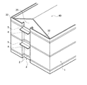
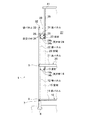
図1は本発明の建物の要部を示す斜視図であり、図2は図1の建物の平面図である。また、図3は図2のA−A部分を示す鉛直断面図であり、図4は図2のB−B部分を示す鉛直断面図である。 FIG. 1 is a perspective view showing the main part of the building of the present invention, and FIG. 2 is a plan view of the building of FIG. 3 is a vertical sectional view showing the AA portion of FIG. 2, and FIG. 4 is a vertical sectional view showing the BB portion of FIG.
建物の基礎6の上部には、台輪7を介して1階の床10を構成する床パネル11及び半土台8が配置されている。その上部には、1階の外周壁1を構成する壁パネル12が配置されている。
On the upper part of the
また、建物の外周部分には、外周壁1と垂直に1対の控え壁2が設けられて凹部3が形成されている。凹部3には、図3に示すように、玄関や窓等の開口部4が設けられている。これらの開口部4は、建物の正面外観を構成するとともに、換気や採光の役割を果たす。また、開口部4から外の景色を眺望することができる。
開口部4の上部には、開口部4に入射する光を調光・遮光する庇5が設けられている。
In addition, a
On the upper part of the opening 4, there is provided a
1階の外周壁1を構成する壁パネル12の上部には、図4に示すように、2階の床20を構成する床パネル21が支持されている。また、壁パネル12と離間して、壁パネル12の上端と同じ高さかつ壁パネル12と平行に、壁パネル12とともに床パネル21を支持する梁材13が設けられている。梁材13は壁パネル12と垂直な耐力壁(図示せず)により両端部を支持されている。
As shown in FIG. 4, a floor panel 21 constituting the
また、梁材13の下端と壁パネル12との間には、天井材14が設けられている。ここで天井材14は、枠状の野縁14aに、必要に応じて補強桟材が設けられ、下面に面材14bが貼り付けられたものである。天井材14は、接着剤やスクリューボルト等を用いて梁材13の下端と壁パネル12との間に取り付けられる。
A ceiling member 14 is provided between the lower end of the beam member 13 and the wall panel 12. Here, the ceiling material 14 has a frame-
壁パネル12、梁材13、床パネル21、及び天井材14により、筒状の構造が形成されている。
1階の床10と天井材14との間の空間15には、収納スペースとして、あるいは展示スペースとして利用することができる図示しない収納ユニット等が設けられる。
A cylindrical structure is formed by the wall panel 12, the beam material 13, the floor panel 21, and the ceiling material 14.
A space 15 between the
床パネル21の、1階の壁パネル12に支持される端部には、必要に応じて調整材9が配置されている。床パネル21及び調整材9の上部には、2階の外周壁1を構成する壁パネル22が配置されている。
外周壁1には、図1に示すように、1階と同様に凹部3が形成されており、窓やベランダ等の開口部4が設けられている。また、開口部4の上部には、1階と同様に庇5が設けられている。
An
As shown in FIG. 1, a
2階の壁パネル22の上部には、図4に示すように、胴差26を介してパラペット壁32を構成する壁パネル33が設けられている。また、壁パネル22と離間して、壁パネル22の上端と同じ高さかつ壁パネル22と平行に、梁材23が設けられている。梁材23は壁パネル22と垂直な耐力壁(図示せず)により両端部を支持されている。梁材23は胴差26を介して妻壁35を支持している。
On the upper part of the wall panel 22 on the second floor, as shown in FIG. 4, a wall panel 33 constituting a
妻壁35は、図2に示すように、外周壁1の直上のパラペット壁32と平行かつ所定間隔離間して配置されている。妻壁35とパラペット壁32の間には陸屋根30が形成されている。妻壁35は2つあり、建物の両端部に平行に設けられている。2つの妻壁35の間には、大空間の居室27が形成されている。また、2つの妻壁35は上端で、図示しない屋根梁の両端部を支持している。
As shown in FIG. 2, the
また、妻壁35と垂直な外周壁1を構成する2階の壁パネル22と胴差26との境界部分の内周面には、図示しない屋根受け材が設けられている。屋根梁及び屋根受け材は、勾配屋根(切妻屋根40)を構成する屋根パネル41を支持している。
In addition, a roof receiving material (not shown) is provided on the inner peripheral surface of the boundary portion between the wall panel 22 on the second floor and the
壁パネル22と胴差26との境界部分の内周面、及び、梁材23の上端と胴差26との境界部分の外周壁1側の面には、陸屋根30を構成する床パネル31を支持する床受け材34がそれぞれ設けられている。また、梁材23の下端と壁パネル22との間には、天井材24が設けられている。天井材24は、天井材14と同様に、枠状の野縁24aに、必要に応じて補強桟材が設けられ、下面に面材24bが貼り付けられたものである。天井材24は、天井材14と同様に、接着剤やスクリューボルト等を用いて梁材23の下端と壁パネル22との間に取り付けられる。
On the inner peripheral surface of the boundary portion between the wall panel 22 and the
2階の床20と天井材24との間の空間26には、収納スペースとして、あるいは展示スペースとして利用することができる図示しない収納ユニット等が設けられる。
壁パネル22、梁材23、床パネル31、及び天井材24により、1階と同様に筒状の構造が形成されている。
In a
The wall panel 22, the beam material 23, the floor panel 31, and the ceiling material 24 form a cylindrical structure as in the first floor.
これらの筒状の構造では、床パネル21、31及び天井材14、24が、壁パネル12、22と梁材13、23との間で水平力を伝達するため、より大きな水平力に抗することができる。したがって、建物のせん断耐力を高め、構造強度を向上させることができる。このため、筒状の構造の外周壁1と反対側の壁や床を省略することができ、吹き抜け等の大空間の広間を形成することができる。
In these cylindrical structures, since the floor panels 21 and 31 and the ceiling members 14 and 24 transmit a horizontal force between the wall panels 12 and 22 and the beam members 13 and 23, they resist a larger horizontal force. be able to. Therefore, the shear strength of the building can be increased and the structural strength can be improved. For this reason, the wall and floor on the opposite side to the outer
また、これらの筒状の構造の内部に、電気配線や情報配線等の配線や、ガスや水道の配管や換気用の配管、汚水や雑排水の配管、雨水排水用の配管等の配管を設けてもよい。さらに、筒状の構造の内部に断熱材を設けてもよいし、筒状の構造の内部を小屋裏換気に用いてもよい。 Also, inside these cylindrical structures, wiring such as electrical wiring and information wiring, piping for gas and water, piping for ventilation, piping for sewage and miscellaneous drainage, piping for rainwater drainage, etc. are provided. May be. Furthermore, you may provide a heat insulating material inside a cylindrical structure, and you may use the inside of a cylindrical structure for hut ventilation.
床パネル31には、図2に示すように、雨水を排水するドレーン管36が埋設されている。床パネル31の上面の高さは、勾配屋根の軒側端部よりも低い。このため、勾配屋根に降った雨は、パラペット壁32に沿って流れ、床パネル31上に流入し、ドレーン管36によって排水される。
As shown in FIG. 2, a
なお、筒状の構造の上側の床パネル21、31は、例えば床受け材34により着脱自在に支持させてもよい。床パネル21、31を着脱自在とすることで、筒状の構造の内部に設けられた配線や配管等のメンテナンスを行うことができる。また、筒状の構造の内部に配線や配管等を後施工することができる。 In addition, you may support the floor panels 21 and 31 of the upper side of a cylindrical structure so that attachment or detachment is possible by the floor receiving material 34, for example. By making the floor panels 21 and 31 attachable and detachable, maintenance of wiring, piping, and the like provided inside the cylindrical structure can be performed. Moreover, wiring, piping, etc. can be post-constructed inside the cylindrical structure.
あるいは、床パネル21、31に図示しない点検口を設けてもよい。床パネル21、31に点検口を設けた場合にも、筒状の構造の内部に設けられた配線や配管等のメンテナンスを行ったり、筒状の構造の内部に配線や配管等を後施工したりすることができる。 Or you may provide the inspection port which is not illustrated in the floor panels 21 and 31. FIG. Even when inspection ports are provided in the floor panels 21 and 31, maintenance of wiring and piping provided inside the cylindrical structure is performed, and wiring and piping are post-installed inside the cylindrical structure. Can be.
床パネル21を着脱自在とした場合、あるいは床パネル21に点検口を設けた場合には、2階から筒状の構造の内部をメンテナンスすることができる。また、陸屋根30を構成する床パネル31を着脱自在とした場合、あるいは床パネル31に点検口を設けた場合には、陸屋根30の上から筒状の構造の内部をメンテナンスすることができる。
When the floor panel 21 is detachable or when an inspection port is provided in the floor panel 21, the inside of the cylindrical structure can be maintained from the second floor. Moreover, when the floor panel 31 which comprises the
なお、以上の実施の形態においては、壁パネル22と離間して、壁パネル22の上端と同じ高さかつ壁パネル22と平行に梁部材を設け、壁パネル22と梁部材により支持される床パネル11を設けるとともに、梁部材の下端と壁パネル22との間に天井材24を設けて筒状の構造を形成したが、本発明はこれに限らず、例えば床パネル21の上部に梁部材を設け、梁部材の上端と壁パネル22との間に床パネル11を設けて筒状の構造を形成してもよい。 In the above embodiment, a beam member is provided spaced apart from the wall panel 22, the same height as the upper end of the wall panel 22, and parallel to the wall panel 22, and the floor supported by the wall panel 22 and the beam member. While the panel 11 is provided and the ceiling member 24 is provided between the lower end of the beam member and the wall panel 22 to form a cylindrical structure, the present invention is not limited to this, and for example, the beam member is formed above the floor panel 21. And the floor panel 11 may be provided between the upper end of the beam member and the wall panel 22 to form a cylindrical structure.
また、外周壁1の開口部4が設けられる位置に凹部3を設けず、連続した筒状の構造を形成してもよい。その他具体的な細部構造についても適宜変更可能であることはもちろんである。
Further, a continuous cylindrical structure may be formed without providing the
11、21、31 床パネル
12、22、33 壁パネル
13、23 梁材
14、24 天井材
15、25 空間
34 床受け材
11, 21, 31 Floor panel 12, 22, 33 Wall panel 13, 23 Beam material 14, 24
Claims (5)
躯体を構成する耐力壁と所定間隔離間し、該耐力壁の上端と同じ高さかつ前記耐力壁と平行に水平方向に延在する梁材が設けられ、この梁材と前記耐力壁とを連結する2つの構造材が上下に離間して水平方向に延在して設けられ、
前記上側の構造材が前記耐力壁及び前記梁材に支持され、
前記下側の構造材が前記耐力壁と前記梁材の下端との間に取り付けられていることを特徴とする建物。 It is a building constructed by the panel method,
A beam member that is spaced apart from the bearing wall constituting the frame by a predetermined distance and extends in the horizontal direction in parallel to the bearing wall is provided at the same height as the upper end of the bearing wall, and the beam member and the bearing wall are connected to each other. Two structural materials are provided to extend horizontally in the vertical direction ,
The upper structural material is supported by the load-bearing wall and the beam material,
The building according to claim 1, wherein the lower structural member is attached between the load-bearing wall and a lower end of the beam member .
Priority Applications (1)
| Application Number | Priority Date | Filing Date | Title |
|---|---|---|---|
| JP2004138480A JP4642378B2 (en) | 2004-05-07 | 2004-05-07 | building |
Applications Claiming Priority (1)
| Application Number | Priority Date | Filing Date | Title |
|---|---|---|---|
| JP2004138480A JP4642378B2 (en) | 2004-05-07 | 2004-05-07 | building |
Publications (2)
| Publication Number | Publication Date |
|---|---|
| JP2005320730A JP2005320730A (en) | 2005-11-17 |
| JP4642378B2 true JP4642378B2 (en) | 2011-03-02 |
Family
ID=35468191
Family Applications (1)
| Application Number | Title | Priority Date | Filing Date |
|---|---|---|---|
| JP2004138480A Expired - Fee Related JP4642378B2 (en) | 2004-05-07 | 2004-05-07 | building |
Country Status (1)
| Country | Link |
|---|---|
| JP (1) | JP4642378B2 (en) |
Families Citing this family (1)
| Publication number | Priority date | Publication date | Assignee | Title |
|---|---|---|---|---|
| JP2008196264A (en) * | 2007-02-15 | 2008-08-28 | Misawa Homes Co Ltd | Structure of balcony |
Citations (8)
| Publication number | Priority date | Publication date | Assignee | Title |
|---|---|---|---|---|
| JPS5585406U (en) * | 1978-12-06 | 1980-06-12 | ||
| JPS63110329A (en) * | 1986-10-29 | 1988-05-14 | ナショナル住宅産業株式会社 | Building |
| JPH0693678A (en) * | 1992-09-10 | 1994-04-05 | Natl House Ind Co Ltd | Floor frame body of house |
| JPH0748894A (en) * | 1993-08-04 | 1995-02-21 | Natl House Ind Co Ltd | Floor structure |
| JPH0842125A (en) * | 1994-08-02 | 1996-02-13 | Misawa Homes Co Ltd | Pipe space construction work method of unit type building and its pipe space structure |
| JP2565626B2 (en) * | 1992-08-31 | 1996-12-18 | ミサワホーム株式会社 | Gate type panel unit |
| JPH11101006A (en) * | 1997-09-29 | 1999-04-13 | Misawa Homes Co Ltd | Housing structure |
| JP2004011303A (en) * | 2002-06-07 | 2004-01-15 | Misawa Homes Co Ltd | Exterior wall panel, unit building equipped with exterior wall panel, and method for mounting shutter case on exterior wall panel |
-
2004
- 2004-05-07 JP JP2004138480A patent/JP4642378B2/en not_active Expired - Fee Related
Patent Citations (8)
| Publication number | Priority date | Publication date | Assignee | Title |
|---|---|---|---|---|
| JPS5585406U (en) * | 1978-12-06 | 1980-06-12 | ||
| JPS63110329A (en) * | 1986-10-29 | 1988-05-14 | ナショナル住宅産業株式会社 | Building |
| JP2565626B2 (en) * | 1992-08-31 | 1996-12-18 | ミサワホーム株式会社 | Gate type panel unit |
| JPH0693678A (en) * | 1992-09-10 | 1994-04-05 | Natl House Ind Co Ltd | Floor frame body of house |
| JPH0748894A (en) * | 1993-08-04 | 1995-02-21 | Natl House Ind Co Ltd | Floor structure |
| JPH0842125A (en) * | 1994-08-02 | 1996-02-13 | Misawa Homes Co Ltd | Pipe space construction work method of unit type building and its pipe space structure |
| JPH11101006A (en) * | 1997-09-29 | 1999-04-13 | Misawa Homes Co Ltd | Housing structure |
| JP2004011303A (en) * | 2002-06-07 | 2004-01-15 | Misawa Homes Co Ltd | Exterior wall panel, unit building equipped with exterior wall panel, and method for mounting shutter case on exterior wall panel |
Also Published As
| Publication number | Publication date |
|---|---|
| JP2005320730A (en) | 2005-11-17 |
Similar Documents
| Publication | Publication Date | Title |
|---|---|---|
| US4759160A (en) | Prefabricated concrete buildings with monolithic roof, wall, and floor members | |
| US20170260737A1 (en) | Prefabricated house | |
| JP4642378B2 (en) | building | |
| JP5312163B2 (en) | Unit building | |
| JPH04309636A (en) | Building panel, wooden building made up of this panel, and its construction method | |
| JP3759816B2 (en) | Building roof structure | |
| JP6535199B2 (en) | Roof construction | |
| JP2002201714A (en) | Unit building | |
| JP5775333B2 (en) | Unit for balcony, unit type building and construction method for unit type building | |
| JP4355244B2 (en) | building | |
| JP7334384B2 (en) | unit building | |
| JP3053732B2 (en) | Unit building | |
| JP2003336312A (en) | Building | |
| KR100711484B1 (en) | Stand-alone construction equipment and construction method of middle-tier steel house using it | |
| JP2003232098A (en) | House with extension eaves | |
| JPH08253970A (en) | Building unit | |
| JPH03217531A (en) | Roofing unit for industrialized housing | |
| JP3902847B2 (en) | Unit building with balcony | |
| JPH02209537A (en) | Panel type structure | |
| JPH11148178A (en) | Manufacture of attic space unit in unit type building | |
| JP2001073463A (en) | Building unit and unit building | |
| JPH0124264Y2 (en) | ||
| JP2000336753A (en) | Unit building | |
| JP2003328444A (en) | Building | |
| JP2000073594A (en) | Building with solar cell roof |
Legal Events
| Date | Code | Title | Description |
|---|---|---|---|
| A621 | Written request for application examination |
Free format text: JAPANESE INTERMEDIATE CODE: A621 Effective date: 20070427 |
|
| A711 | Notification of change in applicant |
Free format text: JAPANESE INTERMEDIATE CODE: A712 Effective date: 20080118 |
|
| RD04 | Notification of resignation of power of attorney |
Free format text: JAPANESE INTERMEDIATE CODE: A7424 Effective date: 20080208 |
|
| A977 | Report on retrieval |
Free format text: JAPANESE INTERMEDIATE CODE: A971007 Effective date: 20090618 |
|
| A131 | Notification of reasons for refusal |
Free format text: JAPANESE INTERMEDIATE CODE: A131 Effective date: 20100622 |
|
| A521 | Written amendment |
Free format text: JAPANESE INTERMEDIATE CODE: A523 Effective date: 20100819 |
|
| TRDD | Decision of grant or rejection written | ||
| A01 | Written decision to grant a patent or to grant a registration (utility model) |
Free format text: JAPANESE INTERMEDIATE CODE: A01 Effective date: 20101124 |
|
| A01 | Written decision to grant a patent or to grant a registration (utility model) |
Free format text: JAPANESE INTERMEDIATE CODE: A01 |
|
| A61 | First payment of annual fees (during grant procedure) |
Free format text: JAPANESE INTERMEDIATE CODE: A61 Effective date: 20101201 |
|
| R150 | Certificate of patent or registration of utility model |
Ref document number: 4642378 Country of ref document: JP Free format text: JAPANESE INTERMEDIATE CODE: R150 Free format text: JAPANESE INTERMEDIATE CODE: R150 |
|
| FPAY | Renewal fee payment (event date is renewal date of database) |
Free format text: PAYMENT UNTIL: 20131210 Year of fee payment: 3 |
|
| LAPS | Cancellation because of no payment of annual fees |