JP4635596B2 - Packaging equipment - Google Patents
Packaging equipment Download PDFInfo
- Publication number
- JP4635596B2 JP4635596B2 JP2004364537A JP2004364537A JP4635596B2 JP 4635596 B2 JP4635596 B2 JP 4635596B2 JP 2004364537 A JP2004364537 A JP 2004364537A JP 2004364537 A JP2004364537 A JP 2004364537A JP 4635596 B2 JP4635596 B2 JP 4635596B2
- Authority
- JP
- Japan
- Prior art keywords
- product
- belt sheet
- printing
- sheet
- packaging
- Prior art date
- Legal status (The legal status is an assumption and is not a legal conclusion. Google has not performed a legal analysis and makes no representation as to the accuracy of the status listed.)
- Expired - Fee Related
Links
Images


Landscapes
- Basic Packing Technique (AREA)
- Auxiliary Devices For And Details Of Packaging Control (AREA)
Description
本発明は、食品をトレー等の容器に収容した商品を包装する包装装置に関し、詳しくは包装材に、商品に関する情報などを印字する印字手段を備えた包装装置に関する。 The present invention relates to a packaging device for packaging a product in which food is stored in a container such as a tray, and more particularly to a packaging device provided with a printing unit for printing information on the product on a packaging material.
商品を包装する包装材に直接印字を行い、その印字された包装材により商品を包装する包装装置、例えば商品の外周に沿ってテープ状の包装材をループ状に巻いて帯掛けする包装装置は既に知られている(例えば、特許文献1参照)。 A packaging device that prints directly on a packaging material that wraps the product and wraps the product with the printed packaging material, such as a packaging device that wraps a tape-shaped packaging material in a loop shape along the outer periphery of the product. It is already known (see, for example, Patent Document 1).
しかしながら、使用する包装材の種類(材質、色等)、叉は包装される商品(商品自体叉は商品を収容する容器)の色によっては、包装材に印字された内容が見えにくくなったりする。例えば、透明な包装材にバーコード等が印字されている場合、その包装材で包装される商品表面の色が黒色の時には、前記バーコードが読取装置(スキャナー)にて読み取り不能になる場合が発生する、という問題があった。 However, depending on the type (material, color, etc.) of the packaging material used or the color of the product to be packaged (the product itself or the container for storing the product), the contents printed on the packaging material may be difficult to see. . For example, when a barcode or the like is printed on a transparent packaging material, the barcode may become unreadable by a reading device (scanner) when the color of the surface of the product packaged with the packaging material is black. There was a problem that it occurred.
本発明は上記した従来の技術が有する問題点に鑑みてなされたもので、その課題とするところは、商品を包装する包装材の色や包装される商品の色に係わらず、包装材に印字された内容が読取装置で確実に読み取られる印字手段を備えた包装装置を提供することにある。 The present invention has been made in view of the above-described problems of the prior art, and the problem is to print on the packaging material regardless of the color of the packaging material for packaging the product or the color of the product to be packaged. Another object of the present invention is to provide a packaging device provided with a printing unit that can surely read the read contents with a reading device.
上記課題を解決するために本発明が講じた技術的手段は、帯シートを包装部に供給して商品を包装する包装装置において、透明部材からなる帯シートを包装部に供給するフィード手段と、帯シートが繰り出される搬送路近傍に、帯シートに不透明物質を付着させる付着手段と、前記包装部と前記付着手段との間に配置され、前記帯シートに直接的或いは間接的に印字を行う印字手段と、商品毎に、品名、値段等の商品情報が設定されている商品ファイルと、該商品ファイルの商品を特定する特定手段と、前記商品情報を帯シートに対して印字するための印字位置情報が設定されている印字フォーマットファイルと、該印字フォーマットファイルから印字位置情報を読み出す読み出し手段と、を備え、読み出された印字位置情報に基づき、前記付着手段により帯シートに不透明物質を付着させ、前記印字手段にて不透明物質が付着されたエリアと対向する反対面の帯シートのエリア叉は不透明物質上に前記特定手段により特定された商品の商品情報を印字することを特徴とする(請求項1)。
上記包装装置は、帯掛け包装装置に限らず、ピロー包装装置、製袋包装装置等、何れでもよいものである。
上記不透明物質の形態は、固体(例えば、シール片等)の形態、或いは液状(例えば、塗料等)の形態等、何れでもよく、液状の場合は塗布することで所定厚さの不透明物質の層が形成されるものであればよい。
上記付着手段としては、不透明物質が固体物(例えば、シール片等)である場合は貼付装置が、不透明物質が液状物である場合は塗布装置を使用することができる。叉、固形物の貼付、液状物の塗布は、印刷面叉は印刷面と反対側の面の何れでもよいが、印刷面の場合は、印字のエリアと不透明物質のエリアとが合致する必要があるし、印刷面と反対側の場合は、不透明物質が貼付或いは塗布されたエリアと対向する裏側の包装材のエリアに直接印字されるようにする。
Technical measure taken by the present invention for solving the above problems is the packaging apparatus for packaging a product by supplying a band sheet packaging unit, and a feed means for feeding the strip sheet made of a transparent member on the packaging unit, An adhering means for adhering an opaque substance to the band sheet in the vicinity of the conveyance path through which the band sheet is fed , and a print which is directly or indirectly printed on the band sheet , disposed between the packaging unit and the adhering means. Means, a product file in which product information such as product name and price is set for each product, a specifying means for specifying the product in the product file, and a printing position for printing the product information on the belt sheet a print format file information is set, and a reading means for reading the print position information from the indicia shaped format file, based on the read printing position information, the An opaque substance is attached to the belt sheet by the attaching means, and the product of the product specified by the specifying means on the area of the belt sheet opposite to the area where the opaque substance is attached by the printing means or on the opaque substance Information is printed (claim 1).
The packaging device is not limited to a banding packaging device, and may be a pillow packaging device, a bag making packaging device, or the like.
The opaque material may be in the form of a solid (for example, a seal piece) or a liquid (for example, paint), etc. In the case of a liquid, a layer of opaque material having a predetermined thickness is applied. What is necessary is just to be formed.
As the attachment means, a sticking device can be used when the opaque substance is a solid substance (for example, a seal piece or the like), and a coating apparatus can be used when the opaque substance is a liquid substance. In addition, solid material sticking and liquid material application may be on either the printing surface or the surface opposite to the printing surface, but in the case of the printing surface, it is necessary that the printed area and the opaque material area match. In the case of the side opposite to the printing surface, printing is performed directly on the area of the packaging material on the back side opposite to the area where the opaque substance is applied or applied.
上記手段によれば、透明な帯シートに不透明物質を付着し、その不透明物質の付着部分に印字を行なうため、印字内容が明確に表示される。そして、読取装置による読み取りに問題が生じない内容については、不透明物質を付着することなく帯シートに直接印字する。 According to the above means, an opaque substance is attached to the transparent belt sheet , and printing is performed on the attached part of the opaque substance, so that the printed content is clearly displayed. And about the content which does not produce a problem in the reading by a reader, it prints directly on a belt sheet , without adhering an opaque substance.
上記包装装置の具体例として帯掛け包装装置を挙げると、その構成は、商品載置部を囲むように包装材の帯シートをループ状に繰り出し、その帯シートの先端部を固定し、反対側を引き戻して初期ループを商品外周に沿うループに絞り、帯シートの先端部と重合する部分を接着し切断して帯掛け包装をする包装部を有する包装装置において、透明部材からなる帯シートを包装部に供給するフィード手段と、帯シートが繰り出される搬送路近傍に、帯シートに不透明物質を付着させる付着手段と、前記包装部と前記付着手段との間に配置され、帯シートに直接的或いは間接的に印字を行う印字手段と、商品毎に、品名、値段等の商品情報が設定されている商品ファイルと、該商品ファイルの商品を特定する特定手段と、前記商品情報を帯シートに対して印字するための印字位置情報が設定されている印字フォーマットファイルと、該印字フォーマットファイルから印字位置情報を読み出す読み出し手段と、を備え、読み出された印字位置情報に基づき、前記付着手段により帯シートに不透明物質を付着させ、前記印字手段にて不透明物質が付着されたエリアと対向する反対面の帯シートのエリア叉は不透明物質上に前記特定手段により特定された商品の商品情報を印字することを特徴とする(請求項2)。 As a specific example of the wrapping device, the wrapping wrapping device has a configuration in which the wrapping material belt sheet is looped out so as to surround the product placement portion, the front end portion of the belt sheet is fixed, and the opposite side In the packaging device having a packaging part for wrapping and wrapping the band sheet by bonding the upper part of the belt sheet and the overlapping part, and wrapping the band sheet made of a transparent member A feeding means for supplying to the part, an adhesion means for adhering an opaque substance to the belt sheet in the vicinity of a conveying path through which the belt sheet is fed, and disposed between the packaging part and the adhesion means, Printing means for performing printing indirectly, a product file in which product information such as a product name and price is set for each product, a specifying unit for specifying a product in the product file, and the product information in a belt sheet A printing format file in which printing position information for printing is set, and a reading means for reading the printing position information from the printing format file. Based on the read printing position information, the attachment means An opaque substance is attached to the belt sheet , and the product information of the product specified by the specifying means is printed on the area of the belt sheet opposite to the area where the opaque material is attached by the printing means or on the opaque material. (Claim 2).
上記手段によれば、商品毎に設定された商品情報の印字フォーマットに基づいて包装材の帯シートに不透明物質が付着されるので、印字内容に応じて決まったタイミングで不透明物質を帯シートに付着し、且つ印字することができる。
該印字フォーマットファイルから印字位置情報を読み出す読み出し手段は問わない。つまり、商品特定手段により商品が特定され、印字フォーマットファイルから印字位置情報を、特定された商品の商品情報とは別に、読み出すようにしてもよいし、或いは、各商品に印字位置情報の識別子を割振っておき、商品が特定されたら、印字位置情報も特定され、読み出されるようにしてもよい。
According to the above means, since the opaque substance is attached to the belt sheet of the packaging material based on the print format of the product information set for each product, the opaque substance is attached to the belt sheet at a timing determined according to the printing content. And can be printed.
Any reading means for reading the print position information from the print format file may be used. That is, the product is specified by the product specifying means, and the print position information may be read from the print format file separately from the product information of the specified product, or the identifier of the print position information may be assigned to each product. If the product is allocated and the product is specified, the print position information may also be specified and read out.
そして、不透明物質を帯シートに付着させる付着手段の起動は、不透明物質上に印字される特定の印字項目の印字位置情報に基づき起動するようにしてもよい(請求項3)。
この手段によれば、印字内容によって不透明物質を付着させる付着手段が起動するため、不透明物質の付着位置と、不透明物質上に印字する印字項目の位置が合致し、安定した印字を行なうことができる。
The activation of the adhering means for adhering the opaque substance to the belt sheet may be activated based on the print position information of a specific print item printed on the opaque substance.
According to this means, since the attaching means for attaching the opaque substance is activated depending on the printing contents, the attachment position of the opaque substance matches the position of the print item to be printed on the opaque substance, and stable printing can be performed. .
更に、帯シートに付着する不透明物質は、固体物又は液状物の何れでもよいが、固体物としてラベル用紙を使用してもよい(請求項4)。
この場合は、ラベル用紙(不透明物質)を帯シートに容易に付着(貼付)することができると共に、必要事項の印字も容易に行うことができる。
Further, the opaque substance adhering to the belt sheet may be either solid or liquid, but label paper may be used as the solid (Claim 4).
In this case, the label paper (opaque substance) can be easily attached (attached) to the belt sheet , and necessary items can be easily printed.
そして、前記帯シートに付着される不透明物質上にはバーコードを印字する(請求項5)。
この場合は、不透明物質上にバーコードが印字されるため、バーコードが読み取り不可能になることはない。
Then, on an opaque material to be deposited before the SL band sheet for printing a bar code (claim 5).
In this case, since the barcode is printed on the opaque substance, the barcode is not unreadable.
本発明の包装装置は請求項1記載の構成により、帯シートに不透明物質が付着され、その不透明物質の付着部分又は不透明物質の付着部分と対応する反対の面に印字が施されるので、印字内容が明確に現出される。また、読み取りなどに問題の生じない印字内容については、不透明物質がなくても帯シートに直接印字できる為、不透明物質の使用量を最小限に抑えることができる。
又、請求項2記載の構成により、帯シートで商品を帯掛け包装する包装装置において、商品情報の印字フォーマットに基づいて不透明物質が付着されるので、印字項目に対応して決まったタイミングで不透明物質を帯シートに付着し、印字することができる。
According to the packaging device of the present invention, an opaque substance is attached to the belt sheet , and printing is performed on the opposite side of the attached part of the opaque substance or the attached part of the opaque substance. The contents appear clearly. In addition, since the printing contents that do not cause problems in reading and the like can be printed directly on the belt sheet without any opaque material, the amount of opaque material used can be minimized.
Further, according to the configuration of the second aspect, in the packaging device for wrapping and wrapping the product with the belt sheet, the opaque substance is adhered based on the print format of the product information, so that it becomes opaque at a timing determined according to the print item. The substance can adhere to the belt sheet and can be printed.
更に、請求項3記載の構成により、印字内容によって不透明物質を付着させる付着手段が起動するため、不透明物質の付着位置の設定作業も容易になる。
また、請求項4記載の構成により、ラベル用紙(不透明物質)を帯シートに付着(貼付)することで、不透明物質の付着を容易に、且つ確実に行うことができる。
請求項5記載の構成により、不透明物質上にバーコードが印字されるため、帯シートが透明であってもバーコードが読み取り不可能になることはない。
Further, according to the third aspect of the present invention, since the attaching means for attaching the opaque substance is activated according to the print content, the setting operation of the attachment position of the opaque substance becomes easy.
According to the fourth aspect of the present invention, by attaching (pasting) the label paper (opaque substance) to the belt sheet, the opaque substance can be easily and reliably attached.
According to the configuration of the fifth aspect, since the barcode is printed on the opaque substance, the barcode is not unreadable even if the belt sheet is transparent.
以下、本発明に係る包装装置の実施の一例を図面に基づいて説明する。
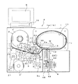
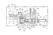
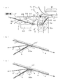
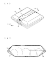
図1乃至図3は包装材として帯シートを使用し、帯シートで商品に帯掛け包装をする帯掛け装置Aの概略を示し、該装置は商品Wの周りに帯シートaを周回させるための初期ループを形成する環状のガイド1と、そのガイド1の側方に配置した帯シートロールa’の装填部2と、前記帯シートaにバーコード印字用のラベル用紙(不透明物質)bを貼付するラベル貼付部(付着手段)3と、前記帯シートaに貼付されたラベル用紙b及び帯シートaに商品情報を印字する印字部(印字手段)4と、商品情報が印字された帯シートを前記環状のガイド1内面に沿って繰り出し及び引き戻すフィード手段5と、初期ループ状態から帯シートの後端側を引き戻して商品Wの外周に沿うループ形状に縮径して帯シートの先端部と重合部を熱溶着する溶着部6と帯シートを切断するカッタ7、及びこれら溶着部6とカッタ7を上下駆動する駆動部8と、更に商品情報等が表示される表示部9と、操作部10とで構成されている。
Hereinafter, an example of implementation of the packaging apparatus according to the present invention will be described with reference to the drawings.
1 to 3 show an outline of a banding device A that uses a band sheet as a packaging material and wraps and wraps a product on the band sheet. The device is used to circulate the band sheet a around the product W. An
上記環状のガイド1は、商品Wの出し入れに供する正面略長方形状の窓孔11を開設した前後一対の側板1a,1bと、その前後の側板1a,1bを帯シートaのテープ幅よりやや広い間隔を置いて対峙させ、且つ前記窓孔の開口縁より所定寸法外側に入った位置に沿って周方向に回した底板1cとで構成され、底板1cの表面が帯シートaの案内面として作用する。そして、底板1cは窓孔の孔縁に沿わせて略楕円形状に湾曲形成され、繰り出される帯シートaがスムーズに案内されて初期ループを確実に形成できるように構成されている。そして、底板1cは繰り出された帯シートaの先端とロールa’に連続する部分が重なってループを形成できるように該底板1cに開設した開口12を挟む始端と終端は上下方向にずらして取り付けられており、更に底板1cの始端側の上方における側板1a,1bの内面にはストッパ13が取り付けられ、帯シートaの先端が位置決めされるように構成されている。
叉、上記ガイド1の窓孔の下側孔縁は商品Wの載置部として機能する。尚、前後の側板に開設する窓孔の形状は長方形状に限定されず、商品の出し入れに支障とならなければ形状は任意である。
The
The lower hole edge of the window hole of the
前記ガイド1の側方に配置した帯シートロールa’の装填部2は、帯掛けの材料となるテープ状の帯シートがロール状に巻かれたロールa’を装填する場所で、中央には帯シートを前記ガイドに向けて繰り出す方向には自由回転し、逆方向には帯シートロールを一体化して駆動回転する一方向クラッチ内蔵の回転軸14が取り付けられており、その回転軸14はモータ15で駆動するように構成されている。この帯シートロールa’がモータ15で逆回転されることで、後述するフィード部5の逆回転による帯シートの引き戻し分を帯シートロールa’に巻き取られる。叉、この装填部2の前面には開閉自在な扉(図示省略)が取り付けられ、帯シートにゴミや埃などが付着しないように構成されている。尚、回転軸14には帯シートが引き出される方向の回転に対して過剰回転を防止する摩擦板ブレーキ構造16が装備されている。
The
上記装填部2に装填された帯シートロールa’の帯シートa先端部は本体ケースに取り付けたガイドローラ17及びガイド板17’を径由してフィード部5に供給され、そのフィード部5の作動で帯シートaは前記ガイド1内側に繰り出される。そして、前記ガイド板17’の途中にはラベル貼付部3が配置され、そのラベル貼付部3より下流側でフィード部5より上流側にはラベル用紙が貼付された帯シートに印字を行う印字部(印字手段)4が配置されている。
The leading end of the belt sheet a of the belt sheet roll a ′ loaded in the
ラベル貼付部(付着手段)3は帯シートが搬送される搬送路近傍に位置し、ロール状に巻いた台紙b’の外側にラベル用紙bを剥離可能に貼付したラベルロールb”と、台紙巻取りリール18と、台紙b’からラベル用紙bを剥離するディスペンサ19と、そのディスペンサ19より下流側に台紙b’から剥離したラベル用紙bを帯シートaに対して貼付するために押え付ける押え部材20が配置されて構成され、前記台紙巻取りリール18がモータ21で駆動回転されることで、ラベルロールb”からラベル用紙bを貼着した台紙b’が引き出されるように構成されている。
そして、ディスペンサ19で台紙b’から剥離されたラベル用紙bは、粘着面を帯シートaに付着して該帯シートaと共に搬送され、その付着状態(貼付状態)をより確実なものとする為に押え部材20で押え付けられる。
その押さえ部材20としては、図4(b)に示す平板部材で構成した押圧ガイド20a、或いは図4(c)に示す押圧ローラ20b等、何れでもよい。
The label sticking part (attachment means) 3 is located near the conveyance path through which the belt sheet is transported, and a label roll b ″ on which the label paper b is detachably attached to the outside of the roll b in a roll form, and the mount winding A take-up reel 18, a
Then, the label paper b peeled from the mount b ′ by the
The pressing
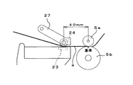
ラベル用紙が貼付された帯シートに商品情報を印字する印字部(印字手段)4は、インクリボン22と、サーマルヘッド23と、プラテンローラ24と、前記プラテンローラ24を駆動回転させるステッピングモータ25と、同プラテンローラ24を上下移動させる移動機構26とで構成され、前記サーマルヘッド23とプラテンローラ24とは対向して配置されている。これにより、帯シートaに商品に関する所定項目が印字され、ラベル用紙bにJANコード(バーコード)が印字される。つまり、ラベル貼付部(付着手段)3にて、帯シートにラベル用紙が貼付されてから印字部(印字手段)4にて帯シートa及びラベル用紙b上への印字がされるので、ラベル貼付部3の位置は、帯シートの搬送路近傍で印字部(印字手段)4より上流であればよい。尚、帯シート及びラベル用紙への印字は、帯シートの先端からの長さによって管理制御される。この点については後段で説明する。
A printing unit (printing means) 4 that prints product information on a belt sheet to which a label sheet is attached includes an
叉、上記印字部(印字手段)4におけるプラテンローラ24は、断面略コ字型に形成したプラテンローラ支持枠27の一側に回転自在に横架支持され、そのプラテンローラ支持枠27の他端側はフレーム28に軸29で上下回動可能に支持されており、更に前記プラテンローラ支持枠27内に支持されたプラテンローラ24の軸部はフレームに開設した円弧案内孔30に嵌挿され、軸29を中心としたプラテンローラ24の上下動が円弧案内孔30によって案内されるように構成されている。
そして、プラテンローラ24をサーマルヘッド23に対して接離させる移動機構26は、前記フレーム28に横架した軸31に前記プラテンローラ支持枠27を下方に押し下げる押圧片32を固着し、軸31の回転による押圧片32の下向き回動で前記プラテンローラ支持枠27が軸29を中心として下方に押し下げられることでプラテンローラ24がサーマルヘッド23に押し付けられる。そして、前記押圧片32を軸着した軸31の回転は、モータ33の回転軸と該軸31とを複数のリンク片34で連結し、モータ33の回転が軸31に伝達されるように構成されている。
The
The moving mechanism 26 for moving the
叉、前記押圧片32を固着した軸31の端部にはプラテンローラ24がサーマルヘッド23に対する接離(開閉)を検出するフラグ35が取り付けられており、そのフラグ35の回動軌跡上にセンサ36,36’が配置されている。更に、プラテンローラ24をサーマルヘッド23に対して当接させる動作は前記したモータ33の回転により行われるが、プラテンローラ24をサーマルヘッド23から離反させる動作は、前記プラテンローラ支持枠27とフレーム28とに亘って引張りバネ37を張設し、この引張りバネ37の張力でプラテンローラ支持枠27が上方に引き上げられ、プラテンローラ24がサーマルヘッド23から離反される。プラテンローラ24の離反は、前記モータ33の回転により押圧片32がプラテンローラ支持枠27から離れる上向き方向に回動された時、前記引張りバネ37が機能して行われる。
尚、押圧片32を固着した軸31の前面側端部には操作レバー38が取り付けられ、手動操作で押圧片32によるプラテンローラ支持枠27の押圧を解除できるように構成されている。
A
An
上記印字部(印字手段)4で所定事項(品名、値段等)の印字Pが行われた帯シートaをガイド1側に供給するフィード手段5は、上下一対のフィードローラ5a,5bで構成され、下側のフィードローラ5bは定位置に支持され、上側のフィードローラ5aは下側のフィードローラ5bに対して接離するよう上下回動可能に支持されている。
そして、下側のフィードローラ5bはモータ5cによって駆動回転するように構成され、上側のフィードローラ5aは前記印字部4におけるプラテンローラ24の上下動(接離動)に連繋して下側のフィードローラ5bに対する接近/離反が切り換わるように構成されている。即ち、印字部(印字手段)4のプラテンローラ24がサーマルヘッド23に接近する印字状態時は上側のフィードローラ5aは下側のフィードローラ5bから離反し、印字手段4のプラテンローラ24がサーマルヘッド23から離反する時は上側のフィードローラ5aは下側のフィードローラ5bと接触するように構成されている。
この上側のフィードローラ5aが下側のフィードローラ5bと接触し、上下のフィードローラ5a,5bによって帯シートaが挾着され、下側のフィードローラ5bが正転方向(時計回り方向)に駆動回転することで帯シートaはガイド1に向けて送り出され、逆転方向(反時計回り方向)に駆動回転することで帯シート1は引き戻される。
The feed means 5 for feeding the belt sheet a on which the predetermined matter (product name, price, etc.) has been printed P by the printing section (printing means) 4 to the
The lower feed roller 5b is configured to be driven and rotated by a
The upper feed roller 5a comes into contact with the lower feed roller 5b, the belt sheet a is attached by the upper and lower feed rollers 5a and 5b, and the lower feed roller 5b is driven in the forward rotation direction (clockwise direction). The belt sheet a is sent out toward the
上側のフィードローラ5aは、矩形状の枠体39に回転可能に横架支持され、その枠体39はフレーム28に対し軸40で上下回動可能に軸支されている。枠体39の回動支点となる軸40の位置は、上側のフィードローラ5aが下方に回動して下側のフィードローラ5bと接触する接点が下側のフィードローラの軸芯を通る鉛直線上となる位置とする。
そして、この前記枠体39は、該枠体39の側近でフレーム28に回動自在に軸支した押圧カム41によって下方に回動されるように構成されている。
上記押圧カム41の回動は、前記印字部(印字手段)4における押圧片32を固着した軸31と押圧カム41とをリンク42で連結し、軸31の回動により押圧カム41がリンク42を介して揺動されるように構成されている(図4(a)参照)。尚、上側のフィードローラ5aを保持した枠体39の上方への回動(フィードローラの離反)は、前記押圧カム41による枠体39の押圧が解除された時、付勢手段64によって軸40を中心として上方に回動することで離反される。
The upper feed roller 5 a is horizontally supported by a
The
The rotation of the
上記フィード手段5の下流側で前記ガイドの下側位置には、前記ガイド1内に供給した帯シートaを該ガイド1の内面に沿って案内し、初期ループを形成し、その後ガイド内に載置した商品Wの外周面に沿うように初期ループを絞って縮径し、帯シートaの先端部と重なり合う部分を熱溶着し、且つ帯シートロールa’に繋がる帯シートaを切断する溶着部6、カッタ7、及びこれら溶着部6とカッタ7を上下駆動する駆動部8が配置されている。
The belt sheet a supplied into the
上記溶着部6は、前記ガイド1の窓孔11における下側の底板1cの開口12内に、帯シートの繰り出し方向に向かい所定間隔をおいて鉛直に起立配置した第1押え板43,第2押え板44と、その第1押え板43と第2押え板44との間に配置した熱溶着板45と、これら第1押え板43、第2押え板44及び熱溶着板45の真上位置にガイド1の側方から出没自在に配置した受け板46とで構成されている。
そして、前記フィード手段5寄りに配置した第1押え板43には上端面より僅か下方位置に帯シートaが嵌挿される通孔47が開設されており、フィード手段5の作動で繰り出される帯シートaの先端はこの通孔47を通ってガイド1に供給される。その為に、第1押え板43より下流側に配置される第2押え板44の上端は前記第1押え板43の通孔47の下側孔縁と面一か或いは下側孔縁より下方となるように配置されている。
叉、第1押え板43と第2押え板44との間に配置する熱溶着板45は、第1押え板43と第2押え板44で帯シートaを押えた後熱溶着する為、該熱溶着板45の上端は第2押え板44の上端より下方に位置されている。
The
The first
In addition, the
前記第1押え板43と熱溶着板45の上端面を受け止める受け板46は、前記ガイド1の側方(裏側)に該ガイドと直交して配置され、且つその受け板46の上面はガイド1の窓孔11の下側孔縁と面一に保持され、ガイド1内に突出して商品載置面を形成する。そして、この受け板46とガイド1の底板1cとで区画される通路(空間)に帯シートaの先端部が嵌入し、その帯シートaの先端部は前記開口12より下流側における側板1a,1bの内面に突出形成したストッパ13に衝合して先端の位置決めが行われる。
A receiving
カッタ7は、帯シートaの重合部を熱溶着してループを完成させた後、そのループに連続する帯シートを溶着部近傍で切断するもので、前記第1押え板43と熱溶着板45との間に挾着配置され、且つ前記第1押え板43の側面に沿って該第1押え板43の通孔47を越える位置まで上下することで、該通孔47を貫通している帯シートaは第1押え板43の通孔47の孔縁とカッタ7によるせん断作用で切断されるように構成されている。
The
上記した溶着部6とカッタ7を上下駆動する駆動部8は、モータ48とカム機構49とで構成され、カム機構49はカムやリンク機構を前記第1押え板43、第2押え板44、熱溶着板45、カッタ7に連結し、更に前記第1押え板43、第2押え板44、熱溶着板45とカッタ7が順次時間差をおいて上下作動するように構成されている。そして、カム機構49の動作を制御する為に該カムを回転する軸に回転板51を固着し、回転板51の外周所定箇所に設けた原点をカム原点センサ52で検知し、駆動部8が制御されるようになっている。
The
叉、前記ガイド1の帯シートaの先端が位置決め停止される位置より手前側(上流側)の所定位置には、帯掛けする為に供給される帯シートaの先端部が所定位置に到達したことを検出する帯シート先端検出センサ(停止センサ)53が配置されている。この帯シート先端検出センサ53の検出信号により前記帯シートaを繰り出すフィード手段5の駆動が停止され、再度駆動して帯シートaの先端がストッパに当接するまでの繰り出しが制御されている。
更に、前記ガイド1における商品Wが載置される位置の線上外側には、商品検出センサ54が設置され、ガイド1内の所定位置に商品Wが置かれているか否かが検出されるようになっており、商品Wが検出されると前記フィード手段5が起動し、帯シートaの引き戻しを開始するようになっている。
In addition, the leading end of the belt sheet a supplied for banding reaches a predetermined position at a predetermined position on the near side (upstream side) from the position where the leading edge of the belt sheet a of the
Further, a
図5は、上記の如く構成した帯掛け装置Aの帯掛けの作動を制御する制御部と、帯掛けの帯シートaに印字を行う印字部の電気的構成を示すブロック図である。
帯掛制御部55は、通信用INFを介して印字制御部56と接続され相互に交信できるようにしてあり、各制御部55,56は、マイクロコンピュータで構成されるCPU(中央処理装置)57,61により制御される。
CPU57には、バス57aを介してROM58、RAM59、帯掛機構駆動部60、帯シート先端検出センサ(停止センサ)53、商品検出センサ54、カム原点センサ52、ラベル貼付部(ラベル発行部)3が接続されている。
ROM58は、CPU57が実行する制御プログラムが格納されており、RAM59には、CPU57とCPU61との通信データ等を一時記憶するエリアである。
FIG. 5 is a block diagram showing an electrical configuration of a control unit that controls the operation of the banding device A configured as described above and a printing unit that performs printing on the banding band sheet a.
The
The
The
前記帯掛機構駆動部60としては、溶着部6の熱溶着板45への通電のON/OFF、プラテンローラ22及び上側フィードローラ5aの開閉駆動モータ33、下側フィードローラ5bの駆動用モータ5c、帯シート巻取り駆動用モータ15、溶着切断手段6及びカッタ7の上下駆動用モータ48、プラテンローラ駆動用モータ25が挙げられ、これ等の駆動/停止が制御される。
The banding
印字制御部56のCPU61には、バス61aを介してROM62、RAM63、表示操作部9、キー操作部10、印字部4が接続されている。
ROM62は、CPU61が実行する制御プログラムが格納されており、RAM63には商品毎の品名等の商品情報を記憶しておく商品ファイル(図8参照)、トレイに関する各種データを記憶しておくトレイファイル(不図示)、帯掛けの帯シート(ラベルを含む)に商品に関する所定の項目を印字する為の印字位置情報を記憶しておく印字フォーマットファイル(図9参照)等のファイルが記憶されている。
表示操作部9は、タッチパネルで構成されており、CPU61の指令に基づいて入力データの表示、プリセットデータの表示、各種メッセージの表示を行うものである。
キー操作部10は、装置の起動、停止等のための各種スイッチ及びデータの入力等を行うキーボードからなる。
A ROM 62, a RAM 63, a display operation unit 9, a
The ROM 62 stores a control program executed by the
The display operation unit 9 is composed of a touch panel, and displays input data, preset data, and various messages based on commands from the
The
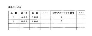
前記RAM63に記憶される商品ファイルは、図8に示すように、品番(商品番号)、品名、値段、印字フォーマット番号等が設けられており、品番を特定することで、各商品を特定することができる(特定手段)。 As shown in FIG. 8, the product file stored in the RAM 63 is provided with a product number (product number), a product name, a price, a print format number, and the like, and each product is specified by specifying the product number. (Specific means)
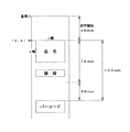
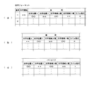
印字フォーマットファイルは、図9(a)、(b)、(c)に示すように、印字フォーマット番号(識別子)毎に印字開始、印字項目(品名、値段、バーコード等)毎の印字位置、及び印字項目毎のラベル貼付の有無を示すフラグ(ラベル貼付)等の印字位置情報が設定されており、印字位置は帯シートの先端からの距離、帯シートの幅に対する位置(帯シートの幅方向の一方端を基点O(0,0)とし、その基点から幅方向(X)、及び長手方向(Y)を始点として、そこからのX方向の幅(印字領域X幅)、Y方向の幅(印字領域Y幅)が設定されている。
印字位置Xは、対応項目の印字エリアについて、印字時における帯シートの進行方向と直交する方向における基点Oから印字開始位置のX座標を表し、ドット単位で示される値である。
印字位置Yは、対応項目の印字エリアについて、印字時における帯シートの進行方向における基点Oから印字開始位置のY座標を表し、ドット単位で示される値である。
印字領域X幅は、対応項目の印字エリアのX座標方向のドット数、印字領域Y幅は対応項目の印字エリアのY座標方向のドット数を表す。上記各ドット数は、キー操作部10の数字キーによる入力により任意の数字に設定することができる。また、本実施例では8ドット分が1mmに該当するようになっている。
尚、JANコード(バーコード)が帯シートにラベル用紙を貼付して印字する場合、JANコードの印字位置データがラベル用紙が貼着された位置と一致するよう貼付部を駆動する。
As shown in FIGS. 9A, 9B, and 9C, the print format file starts printing for each print format number (identifier), print position for each print item (product name, price, barcode, etc.), Also, printing position information such as a flag (label sticking) indicating the presence / absence of label sticking for each print item is set, and the print position is the distance from the leading edge of the belt sheet, the position relative to the belt sheet width (width direction of the belt sheet) One end of the image is defined as a base point O (0, 0), the width direction (X) from the base point and the longitudinal direction (Y) as the start point, the width in the X direction (print area X width), the width in the Y direction (Print area Y width) is set.
The print position X represents the X coordinate of the print start position from the base point O in the direction orthogonal to the traveling direction of the belt sheet at the time of printing for the print area of the corresponding item, and is a value indicated in dot units.
The print position Y represents the Y coordinate of the print start position from the base point O in the traveling direction of the band sheet at the time of printing for the print area of the corresponding item, and is a value indicated in dot units.
The print area X width represents the number of dots in the X coordinate direction of the print area of the corresponding item, and the print area Y width represents the number of dots in the Y coordinate direction of the print area of the corresponding item. The number of dots can be set to any number by inputting with the numeric keys of the
When the JAN code (bar code) is printed by attaching a label sheet to the belt sheet, the application unit is driven so that the print position data of the JAN code matches the position where the label sheet is attached.
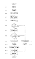
次に、帯シートにラベル用紙(不透明物質)を貼付し、帯シートとラベル用紙に印字し、その印字した帯シートで商品に帯掛けする動作の概略を図10のフローチャートに基づいて説明する。尚、以下の例では各商品に、印字位置情報の識別子である印字フォーマット番号が設定されており、商品が特定されることで当該商品の品名や値段などといった商品情報の印字位置情報が読み出される。
(S1)…帯シートaがセットされていることを確認し、オペレータにより電源スイッチがONされる。電源スイッチがONされるとCPU57は、溶着部6とカッタ部7を上下するカム機構49のカムが初期位置(カム原点センサ52を遮る)に戻るよう制御する。そして、フィード部5が作動して帯シートaの先端を所定位置まで繰り出し、駆動部8が作動してカム機構49が作動することでカッタ7が上昇し、受け板46がカッタ7の上方位置へ突出移動し、受け板46とカッタ7とで帯シートaが挟まれ、帯シートaが切断される。そして、CPU57はフィード手段5を逆回転させて前記帯シートaの切断先端部を該フィード手段5(上下一対のフィードローラの接点間に帯シートの先端が挟まれる位置)へ引き戻し、位置させるよう制御する(図6参照)。この位置が帯シートの初期位置である。尚、印字部(印字手段)4のサーマルヘッドとプラテンローラとの接点からフィード手段5上の初期位置までの距離は装置構成時に決定される。本実施例では、この距離を40mmとする。
Next, an outline of an operation of attaching a label sheet (opaque substance) to the band sheet, printing on the band sheet and the label sheet, and banding the product with the printed band sheet will be described based on the flowchart of FIG. In the following example, a print format number, which is an identifier of print position information, is set for each product. When the product is specified, print position information of product information such as the product name and price of the product is read. .
(S1) ... After confirming that the belt sheet a is set, the operator turns on the power switch. When the power switch is turned on, the
(S2)…表示操作部9に表示された商品情報の商品ファイルから、オペレータの選択操作により、帯掛けする被帯掛け商品Wの品番が選択され(特定手段)、当該品番の商品情報が読み出される。
(S3)…スタートボタンがオペレータにより押される。
(S4)…(S2)で選択された品番に関連付けられている印字フォーマット番号の印字位置情報がRAM63の印字フォーマットファイルより読み出され(読み出し手段)、その読み出された品番の商品情報、印字位置情報がRAM63の他のエリアに一時記憶される。そして、RAM63の他のエリアに一時記憶された印字位置情報の印字開始データが40mmか否かをCPU61が判断する。つまり、該印字開始データから40mmを減算し、その値が“0(ゼロ)”かどうかを判断する。そして、その減算値(差分データ)を前記RAM63の他のエリアに一時記憶する。
(S5)…(S4)で読み出した印字位置情報に基づき、印字開始位置が合わされる。尚、前記印字位置情報には、印字開始データの他に、帯シートaに印字する項目毎に、印字位置の始点である幅方向(X)、長さ方向(Y)、その始点からのX方向の幅、Y方向の幅等のデータ、及びラベル貼付のフラグが設定されている(図9参照)。
(S4)で読み出した印字開始データが40mmでない場合、つまり40mm以上(本実施例では40mmが最小値)と判断された場合は、(S4)で一時記憶された印字位置情報の、印字開始データと初期位置である40mmとの差分データと、更にプラテン/フィードローラ開閉駆動モータ33を駆動させプラテンローラをサーマルヘッドから離反させる信号とを、通信INFを介してCPU61(印字制御部)からCPU57(帯掛制御部)へ送信する。つまり40mm以上(本実施例では40mmが最小値)と判断された場合は、印字部(印字手段)4のプラテンローラがサーマルヘッドから離反するよう上昇する。
印字部(印字手段)4のプラテンローラの上下動と、フィード手段5の上側のフィードローラ5aの上下動は相反する動きをするようリンク結合されているので、フィード部5の上側のフィードローラ5aは下降して下側のフィードローラ5bとで帯シートaを挟持し、(S4)でRAM59に一時記憶した印字開始データと40mmとの差分データ分だけ、フィード部5のフィードローラモータ5cを回転させる。例えば、印字開始データが60mmである場合は、フィードローラモータ5cの駆動で帯シートaの先端を初期位置から20mmだけ前方に繰り出し、印字部(印字手段)4の位置から帯シートaの先端までの長さを60mmに合わせる。
(S2) ... From the product file of the product information displayed on the display operation unit 9, the product number of the banded product W to be banded is selected by the operator's selection operation (identifying means), and the product information of the product number is read out. It is.
(S3) ... The start button is pressed by the operator.
(S4) ... The print position information of the print format number associated with the product number selected in (S2) is read from the print format file in the RAM 63 (reading means), and the product information and print of the read product number are read. The position information is temporarily stored in another area of the RAM 63. Then, the
(S5) ... The print start position is adjusted based on the print position information read in (S4). In addition to the print start data, the print position information includes, for each item to be printed on the belt sheet a, the width direction (X), the length direction (Y), which is the start point of the print position, and the X from the start point. Data such as the width in the direction, the width in the Y direction, and a label pasting flag are set (see FIG. 9).
If the print start data read in (S4) is not 40 mm, that is, if it is determined that it is 40 mm or more (40 mm is the minimum value in this embodiment), the print start data of the print position information temporarily stored in (S4) The CPU 61 (print control unit) sends the difference data between the initial position and 40 mm, which is the initial position, and a signal for driving the platen / feed roller opening /
Since the vertical movement of the platen roller of the printing section (printing means) 4 and the vertical movement of the feed roller 5a on the upper side of the feed means 5 are linked and linked to each other, the feed roller 5a on the upper side of the
(S6)…(S4)でRAM63の他のエリアに一時記憶された印字位置情報に設定された各印字項目にラベル用紙(不透明物質)bを貼付するか否かを示すフラグ(1:貼付する、0:貼付しない)があるかをCPU61が判断する。YESの場合はS7に進む。
(S7)…RAM63からラベル貼付フラグに[1]が設定されている印字項目について、印字位置Yが読み出される。
(S8)…(S7)でRAM63に一時記憶された印字位置情報の印字位置Yのデータが70mm以上か否かをCPU61が判断する。ここで、70mmとは、サーマルヘッド23とラベル貼付部との間隔で、装置の機構的な理由によって決定される。70mmより小さい数値の場合は、ラベル貼付部よりも印字部(印字手段)4寄りになる為、ラベル用紙を貼付することは物理的に不可能である。YESの場合は(S9)に進む。
(S9)…(S7)でRAM63から読み出された印字項目の印字位置Yの座標ドットから70mmに該当する560ドット分を減算し、その減算したデータと、プラテン/フィードローラ開閉駆動モータを駆動させプラテンローラをサーマルヘッドから離反させる信号とを、通信INFを介してCPU61からCPU57へ送信する。
(S6)... Flag indicating whether or not the label paper (opaque substance) b is attached to each print item set in the print position information temporarily stored in the other area of the RAM 63 in (S4) (1: attach) , 0: Do not stick)). If YES, the process proceeds to S7.
(S7)... The print position Y is read from the RAM 63 for the print item in which the label pasting flag is set to [1].
(S8)... The
(S9)... 560 dots corresponding to 70 mm are subtracted from the coordinate dot of the print position Y of the print item read from the RAM 63 in (S7), and the subtracted data and the platen / feed roller opening / closing drive motor are driven. Then, a signal for separating the platen roller from the thermal head is transmitted from the
(S10)…(S5)で既に印字開始位置が合っているので、(S4)で一時記憶された印字位置情報にて印字を開始する。
(S11)…(S9)にて、帯掛制御部側で受信したデータはRAM59の一時記憶エリアに記憶される。そして、CPU57の制御により、(S9)で算出された距離分、ステッピングモータが回転してラベル用紙bを帯シートa上に貼付する。
(S12)…(S6)のラベル貼付フラグ[1]が設定されている印字項目の印字データが設定されている場合には、所定時間経過後にラベル用紙が貼付された帯シート部分が印字部(印字手段)4を通過するので、CPU61の制御により所定の情報、例えばバーコードがラベル用紙b上に印字される。
尚、(S6)でNOの場合は、(S13)に進み、ラベル用紙bは貼付されず、(S14)で帯シートa上に、CPU61の制御により、RAM63に記憶された印字フォーマットファイルと商品ファイルとに基づき印字部(印字手段)4で所定項目の印字が行われる。(S8)の判断がNOの場合も同様である。
(S10)... (S5) Since the print start position is already in alignment, printing is started with the print position information temporarily stored in (S4).
(S11)... (S9), the data received on the band control unit side is stored in the temporary storage area of the
(S12) When the print data of the print item for which the label pasting flag [1] of (S6) is set is set, the band sheet portion to which the label paper is pasted after a predetermined time has passed Since the printing means) 4 passes, predetermined information such as a barcode is printed on the label paper b under the control of the
If (S6) is NO, the process proceeds to (S13), the label paper b is not pasted, and the print format file and the product stored in the RAM 63 under the control of the
上記構成により、搬送される帯シートa上にラベル用紙が貼付され、貼付されたラベル用紙b上に所定事項が印字される。
(S15)…印字が終了したら、CPU57の制御により印字部4のプラテンローラをサーマルヘッドから離反させるモータを駆動させ、これによりプラテンローラがサーマルヘッドから離反し、フィード手段5にて帯シートを挟持する。
そして、フィード手段5により帯シートが所定量繰り出され、ガイド1内の商品載置部に置かれた商品Wに帯シートを帯掛けし、帯シートを商品外周に沿うように縮径させて商品Wへの帯掛け包装が完了する。
以上のようにすることで、帯シートに不透明物質であるラベルを貼付することができ、該ラベル上に例えばバーコード等の所定事項を印字することができ、該ラベルが貼付された帯ラベルによって商品を帯掛け包装することができる。
上記の説明では、各商品に印字位置情報の識別子である印字フォーマット番号が設定されており、商品が特定されることで、当該商品の品名や値段等の印字位置情報が読み出されるような一例を示したがこれに限定されるものではない。例えば、商品が収納されるトレイのサイズ毎にトレイ番号を識別子として定まっているようなトレイファイルを有し、各トレイ番号毎に帯掛け包装の際の帯シートを縮径する絞り量が割振られており、該トレイ番号が各商品(各品番)に設定されているようにしてもよい。これにより、商品が特定されることでトレイ番号も特定され、使用するトレイの大きさに合った帯シートの絞り量にて帯掛け包装をすることができる。
また、前記トレイファイルの各トレイ番号に前記印字フォーマット番号を設定するようにし、該トレイ番号を各商品(各品番)に設定するようにしてもよい。これにより、商品だけを特定することで、当該商品の品名等の商品情報、トレイ番号から特定される使用するトレイに合った絞り量、更には印字フォーマット番号にて特定される印字位置情報が読み出される。
With the above configuration, a label sheet is affixed on the belt sheet a to be conveyed, and predetermined items are printed on the affixed label sheet b.
(S15)... When printing is completed, a motor for driving the platen roller of the
Then, a predetermined amount of the belt sheet is fed out by the feed means 5, the belt sheet is banded on the product W placed on the product mounting portion in the
As described above, a label that is an opaque substance can be affixed to the belt sheet, and a predetermined matter such as a barcode can be printed on the label. Products can be wrapped in wrapping.
In the above description, an example in which a print format number that is an identifier of print position information is set for each product, and the print position information such as the product name and price of the product is read by specifying the product. Although shown, it is not limited to this. For example, there is a tray file in which the tray number is determined as an identifier for each size of the tray in which the product is stored, and the amount of drawing for reducing the diameter of the band sheet during banding packaging is allocated for each tray number. The tray number may be set for each product (each product number). Thus, the tray number is also specified by specifying the product, and banding and packaging can be performed with the band sheet squeezing amount that matches the size of the tray to be used.
Further, the print format number may be set for each tray number of the tray file, and the tray number may be set for each product (each product number). Thus, by specifying only the product, product information such as the product name of the product, the amount of aperture suitable for the tray to be used specified from the tray number, and the print position information specified by the print format number are read out. It is.
また、例えば透明の帯シートaにバーコードを印字する場合、バーコードが印字されている基材(帯シート)が透明なので、バーコードは光学的に読み取り不能になる場合がある。
このような場合に、透明な帯シートの上に不透明物質のラベル用紙bを貼付し、その後、帯シートに貼付されたラベル用紙上にバーコードを印字することで、バーコードは確実に読み取り可能になる。但し、ラベル用紙に印字する内容は特定されず、イメージデータ等でもよい。
また、帯シート(包装材)に貼付するラベル用紙は、無印字のラベル用紙に限らず、予め所定事項が印字されたラベルを用い、帯シートa上の所定位置に貼付するようにしてもよい。例えば、POPラベル等に利用できる。この場合は、上記読み出された印字フォーマットにラベル貼付フラグが設定されており、該当する印字項目の印字内容が設定されていない場合は、帯シートの所定の場所にラベル用紙だけが貼付される。例えば、予めカラー印字された“お買い得”や“おすすめ”等が印字された広告ラベル等は、上記のようにすることで所定の位置に自動的に貼付することが出来る。
Further, for example, when a barcode is printed on a transparent belt sheet a, since the base material (band sheet) on which the barcode is printed is transparent, the barcode may not be optically readable.
In such a case, the label can be reliably read by sticking the opaque label paper b on the transparent belt sheet and then printing the barcode on the label paper pasted on the belt sheet. become. However, the content to be printed on the label paper is not specified and may be image data or the like.
Further, the label paper to be attached to the belt sheet (packaging material) is not limited to the non-printed label paper, and a label on which a predetermined matter is printed in advance may be used and attached to a predetermined position on the belt sheet a. . For example, it can be used for POP labels. In this case, a label pasting flag is set in the read print format, and if the print contents of the corresponding print item are not set, only the label paper is pasted at a predetermined place on the belt sheet. . For example, an advertisement label or the like on which “bargain” or “recommendation” printed in color is printed can be automatically attached at a predetermined position as described above.
上記したフローチャートは、手動モードによる動作であるが、商品載置部近傍に商品センサ54を設け、その商品センサ54により商品Wが検知された時、起動するような自動モードを備えてもよいものである。
その自動モードの場合は、複数の同じ商品を帯掛け包装する場合に、包装する商品毎にスタートキーを操作しなくてよいという利点がある。
以上は透明な帯シートの表裏二面のうち、帯シートへの印字がされる面にラベル用紙を貼付し、該ラベル用紙への印字を行う例を説明したが、これに限らず、透明な帯シートへの印字がされる面とは反対の面にラベル用紙を貼付し、帯シートのラベル用紙が貼付されているエリアの対向する反対の面の帯シート上に印字するようにしてもよい。
これにより、帯シートの反対の面にラベル用紙が貼付されているので、帯シートに印字された事項は、前記ラベル用紙に印字した場合同様、例えば、バーコードは光学的に読み取り可能になる。また、バーコード以外の情報の場合は、印字された帯シートの下面にラベル用紙が貼付されているので、印字された情報が商品の色と混同することがなく、該情報が読み易くなる。
The above-described flowchart is an operation in the manual mode, but an automatic mode may be provided in which a
In the automatic mode, there is an advantage that when a plurality of the same products are wrapped and packaged, it is not necessary to operate the start key for each product to be packaged.
The above has described an example in which label paper is pasted on the surface of the transparent belt sheet that is printed on the belt sheet, and printing is performed on the label paper. A label sheet may be affixed to the side opposite to the side on which the band sheet is printed, and the label sheet may be printed on the opposite side of the band sheet where the label sheet is affixed. .
Thereby, since the label paper is affixed to the opposite surface of the belt sheet, the matter printed on the belt sheet can be optically read, for example, as in the case of printing on the label paper. In the case of information other than the barcode, since the label sheet is attached to the lower surface of the printed belt sheet, the printed information is not confused with the color of the product, and the information is easy to read.
本発明は上記した実施の形態に限定されるものではなく、本発明の要旨を変更しない範囲で変更可能である。
(1)本実施例では帯シートでループを形成する為に環状のガイドを用いたが、ガイドを用いない帯掛け装置でもよいものである。叉、帯掛け装置の包装部の機構は問わない。
(2)包装材の機械読みする印字項目の印字位置エリアの裏側に印刷(例えば白色塗料による)を施し、その印刷した位置の包装材表面にバーコードを印字するようにしてもよい。
(3)本装置の商品載置部に計量装置を配置し、或いは計量装置を接続して、商品の重量を計測し、その計測した重量データを帯シートに印字するようにしてもよい。
(4)印字内容は問わない。被帯掛け商品の産地、添加物名、賞味期限、商品の原体を示す個体識別番号、商品に関する広告データやイメージデータ等を印字してもよい。
(5)電源をONすると同時にリセット動作をするようにしているが、リセット動作のみを実行するスイッチを別途設けてもよい。
The present invention is not limited to the above-described embodiment, and can be changed without changing the gist of the present invention.
(1) In this embodiment, an annular guide is used to form a loop with a band sheet, but a banding device that does not use a guide may be used. In addition, the mechanism of the packaging portion of the banding device is not limited.
(2) Printing (for example, with white paint) may be performed on the back side of the printing position area of the printing item to be read by the machine of the packaging material, and a barcode may be printed on the surface of the packaging material at the printed position.
(3) A weighing device may be arranged on the product placement section of the present device, or a weighing device may be connected to measure the weight of the product, and the measured weight data may be printed on the belt sheet.
(4) The printed content is not limited. The production area of the banded product, the name of the additive, the expiration date, the individual identification number indicating the original product, the advertisement data or the image data related to the product may be printed.
(5) Although the reset operation is performed simultaneously with turning on the power, a switch for executing only the reset operation may be provided separately.
A…帯掛け装置 a…帯シート
b…ラベル用紙 1…ガイド
3…ラベル貼付部(付着手段) 4…印字部(印字手段)
5…フィード部(フィードローラ) 6…溶着部
7…カッタ 8…熱溶着部/カッタの上下駆動部
9…表示部 10…操作部
W…商品
A ... Banding device a ... Band sheet
b ...
3 ... Label sticking part (attachment means) 4 ... Printing part (printing means)
5 ... Feed part (feed roller) 6 ... Welding part
7 ...
9 ...
W ... Product
Claims (5)
透明部材からなる帯シートを包装部に供給するフィード手段と、
帯シートが繰り出される搬送路近傍に、帯シートに不透明物質を付着させる付着手段と、
前記包装部と前記付着手段との間に配置され、前記帯シートに直接的或いは間接的に印字を行う印字手段と、
商品毎に、品名、値段等の商品情報が設定されている商品ファイルと、
該商品ファイルの商品を特定する特定手段と、
前記商品情報を帯シートに対して印字するための印字位置情報が設定されている印字フォーマットファイルと、
該印字フォーマットファイルから印字位置情報を読み出す読み出し手段と、
を備え、読み出された印字位置情報に基づき、前記付着手段により帯シートに不透明物質を付着させ、前記印字手段にて不透明物質が付着されたエリアと対向する反対面の帯シートのエリア叉は不透明物質上に前記特定手段により特定された商品の商品情報を印字することを特徴とする包装装置。 In a packaging device that wraps a product by supplying a belt sheet to a packaging unit,
A feed means for supplying a belt sheet made of a transparent member to the packaging part;
An adhering means for adhering an opaque substance to the belt sheet in the vicinity of the conveyance path through which the belt sheet is fed,
A printing unit disposed between the packaging unit and the adhering unit, and performing printing directly or indirectly on the belt sheet ;
A product file in which product information such as product name and price is set for each product,
A specifying means for specifying a product in the product file;
A print format file in which print position information for printing the product information on the belt sheet is set;
Reading means for reading print position information from the print format file;
An opaque substance is attached to the belt sheet by the attachment means based on the read printing position information, and the area of the belt sheet on the opposite surface opposite to the area where the opaque substance is attached by the printing means A packaging apparatus , wherein product information of a product specified by the specifying means is printed on an opaque substance .
透明部材からなる帯シートを包装部に供給するフィード手段と、
帯シートが繰り出される搬送路近傍に、帯シートに不透明物質を付着させる付着手段と、
前記包装部と前記付着手段との間に配置され、前記帯シートに直接的或いは間接的に印字を行う印字手段と、
商品毎に、品名、値段等の商品情報が設定されている商品ファイルと、
該商品ファイルの商品を特定する特定手段と、
前記商品情報を帯シートに対して印字するための印字位置情報が設定されている印字フォーマットファイルと、
該印字フォーマットファイルから印字位置情報を読み出す読み出し手段と、
を備え、読み出された印字位置情報に基づき、前記付着手段により帯シートに不透明物質を付着させ、前記印字手段にて不透明物質が付着されたエリアと対向する反対面の帯シートのエリア叉は不透明物質上に前記特定手段により特定された商品の商品情報を印字することを特徴とする包装装置。 The belt sheet of the packaging material is fed out in a loop so as to surround the product placement section, the front end portion of the belt sheet is fixed, the opposite side is pulled back, the initial loop is narrowed down to the loop along the outer periphery of the product, and the front end portion of the belt sheet In a packaging device having a packaging part for bonding and cutting a portion to be polymerized and banding and packaging,
A feed means for supplying a belt sheet made of a transparent member to the packaging part;
An adhering means for adhering an opaque substance to the belt sheet in the vicinity of the conveyance path through which the belt sheet is fed,
Wherein disposed between the packing portion and the attachment means, and printing means for performing directly or indirectly printed on the band sheet,
A product file in which product information such as product name and price is set for each product,
A specifying means for specifying a product in the product file;
A print format file in which print position information for printing the product information on the belt sheet is set;
Reading means for reading print position information from the print format file;
An opaque substance is attached to the belt sheet by the attachment means based on the read printing position information, and the area of the belt sheet on the opposite surface opposite to the area where the opaque substance is attached by the printing means A packaging apparatus, wherein product information of a product specified by the specifying means is printed on an opaque substance.
Priority Applications (1)
| Application Number | Priority Date | Filing Date | Title |
|---|---|---|---|
| JP2004364537A JP4635596B2 (en) | 2004-12-16 | 2004-12-16 | Packaging equipment |
Applications Claiming Priority (1)
| Application Number | Priority Date | Filing Date | Title |
|---|---|---|---|
| JP2004364537A JP4635596B2 (en) | 2004-12-16 | 2004-12-16 | Packaging equipment |
Publications (2)
| Publication Number | Publication Date |
|---|---|
| JP2006168793A JP2006168793A (en) | 2006-06-29 |
| JP4635596B2 true JP4635596B2 (en) | 2011-02-23 |
Family
ID=36669958
Family Applications (1)
| Application Number | Title | Priority Date | Filing Date |
|---|---|---|---|
| JP2004364537A Expired - Fee Related JP4635596B2 (en) | 2004-12-16 | 2004-12-16 | Packaging equipment |
Country Status (1)
| Country | Link |
|---|---|
| JP (1) | JP4635596B2 (en) |
Families Citing this family (4)
| Publication number | Priority date | Publication date | Assignee | Title |
|---|---|---|---|---|
| JP4965281B2 (en) * | 2007-02-27 | 2012-07-04 | 株式会社イシダ | Band winding device |
| JP2008207846A (en) * | 2007-02-27 | 2008-09-11 | Teraoka Seiko Co Ltd | Strapping unit |
| JP6408652B1 (en) * | 2017-05-30 | 2018-10-17 | トキワ工業株式会社 | Packaging film processing apparatus, packaging machine, and packaging film processing method |
| JP7456769B2 (en) * | 2019-12-26 | 2024-03-27 | エフピコダイヤフーズ株式会社 | Method for producing egg packaging |
Family Cites Families (2)
| Publication number | Priority date | Publication date | Assignee | Title |
|---|---|---|---|---|
| JPS59174419A (en) * | 1983-03-17 | 1984-10-02 | 日魯工業株式会社 | Packing band type printing packer |
| JP3589534B2 (en) * | 1996-09-26 | 2004-11-17 | 株式会社ユポ・コーポレーション | Tying strap |
-
2004
- 2004-12-16 JP JP2004364537A patent/JP4635596B2/en not_active Expired - Fee Related
Also Published As
| Publication number | Publication date |
|---|---|
| JP2006168793A (en) | 2006-06-29 |
Similar Documents
| Publication | Publication Date | Title |
|---|---|---|
| EP0758955B1 (en) | Linerless label printer and transport system | |
| CN106457850B (en) | printer | |
| JP5407302B2 (en) | Banding device | |
| JP4600026B2 (en) | Banding device | |
| JP2008207846A (en) | Strapping unit | |
| JP4635596B2 (en) | Packaging equipment | |
| JPH092441A (en) | Label printer | |
| JP4929838B2 (en) | Banding method and banding apparatus therefor | |
| JPH06199332A (en) | Title label sticker | |
| JP4650031B2 (en) | Banding device | |
| JP2009083911A (en) | Band winding device | |
| JP4965281B2 (en) | Band winding device | |
| JP5999575B2 (en) | Tape printer | |
| JP4581657B2 (en) | Banding device | |
| JP6380275B2 (en) | Printer, packaging equipment | |
| JP3392460B2 (en) | Tape printer | |
| JP5549075B2 (en) | Banding device | |
| JP7301353B2 (en) | printer | |
| JP2009000973A (en) | Printer | |
| JP3932718B2 (en) | Label writer tape, label writer tape cassette and label writer | |
| JP3941106B2 (en) | Printing tape and tape printer | |
| JP2009073136A (en) | Printer | |
| JP7330479B2 (en) | Belt wrapping device and wrapping method | |
| JP2019119493A (en) | Band binding device | |
| JP2006290370A (en) | Strapping apparatus |
Legal Events
| Date | Code | Title | Description |
|---|---|---|---|
| A621 | Written request for application examination |
Free format text: JAPANESE INTERMEDIATE CODE: A621 Effective date: 20070830 |
|
| RD02 | Notification of acceptance of power of attorney |
Free format text: JAPANESE INTERMEDIATE CODE: A7422 Effective date: 20080327 |
|
| A977 | Report on retrieval |
Free format text: JAPANESE INTERMEDIATE CODE: A971007 Effective date: 20100517 |
|
| A131 | Notification of reasons for refusal |
Free format text: JAPANESE INTERMEDIATE CODE: A131 Effective date: 20100622 |
|
| A521 | Request for written amendment filed |
Free format text: JAPANESE INTERMEDIATE CODE: A523 Effective date: 20100810 |
|
| TRDD | Decision of grant or rejection written | ||
| A01 | Written decision to grant a patent or to grant a registration (utility model) |
Free format text: JAPANESE INTERMEDIATE CODE: A01 Effective date: 20101026 |
|
| A01 | Written decision to grant a patent or to grant a registration (utility model) |
Free format text: JAPANESE INTERMEDIATE CODE: A01 |
|
| A61 | First payment of annual fees (during grant procedure) |
Free format text: JAPANESE INTERMEDIATE CODE: A61 Effective date: 20101108 |
|
| FPAY | Renewal fee payment (event date is renewal date of database) |
Free format text: PAYMENT UNTIL: 20131203 Year of fee payment: 3 |
|
| R150 | Certificate of patent or registration of utility model |
Ref document number: 4635596 Country of ref document: JP Free format text: JAPANESE INTERMEDIATE CODE: R150 Free format text: JAPANESE INTERMEDIATE CODE: R150 |
|
| FPAY | Renewal fee payment (event date is renewal date of database) |
Free format text: PAYMENT UNTIL: 20131203 Year of fee payment: 3 |
|
| R250 | Receipt of annual fees |
Free format text: JAPANESE INTERMEDIATE CODE: R250 |
|
| R250 | Receipt of annual fees |
Free format text: JAPANESE INTERMEDIATE CODE: R250 |
|
| R250 | Receipt of annual fees |
Free format text: JAPANESE INTERMEDIATE CODE: R250 |
|
| R250 | Receipt of annual fees |
Free format text: JAPANESE INTERMEDIATE CODE: R250 |
|
| R250 | Receipt of annual fees |
Free format text: JAPANESE INTERMEDIATE CODE: R250 |
|
| R250 | Receipt of annual fees |
Free format text: JAPANESE INTERMEDIATE CODE: R250 |
|
| R250 | Receipt of annual fees |
Free format text: JAPANESE INTERMEDIATE CODE: R250 |
|
| R250 | Receipt of annual fees |
Free format text: JAPANESE INTERMEDIATE CODE: R250 |
|
| R250 | Receipt of annual fees |
Free format text: JAPANESE INTERMEDIATE CODE: R250 |
|
| R250 | Receipt of annual fees |
Free format text: JAPANESE INTERMEDIATE CODE: R250 |
|
| R250 | Receipt of annual fees |
Free format text: JAPANESE INTERMEDIATE CODE: R250 |
|
| LAPS | Cancellation because of no payment of annual fees |