JP4595479B2 - Game machine - Google Patents

Game machine Download PDF

Info

Publication number
JP4595479B2
JP4595479B2 JP2004293271A JP2004293271A JP4595479B2 JP 4595479 B2 JP4595479 B2 JP 4595479B2 JP 2004293271 A JP2004293271 A JP 2004293271A JP 2004293271 A JP2004293271 A JP 2004293271A JP 4595479 B2 JP4595479 B2 JP 4595479B2
Authority
JP
Japan
Prior art keywords
variable display
winning
game
display
ball
Prior art date
Legal status (The legal status is an assumption and is not a legal conclusion. Google has not performed a legal analysis and makes no representation as to the accuracy of the status listed.)
Active
Application number
JP2004293271A
Other languages
Japanese (ja)
Other versions
JP2006102169A (en
JP2006102169A5 (en
Inventor
裕義 州崎
Current Assignee (The listed assignees may be inaccurate. Google has not performed a legal analysis and makes no representation or warranty as to the accuracy of the list.)
Sanyo Bussan Co Ltd
Original Assignee
Sanyo Bussan Co Ltd
Priority date (The priority date is an assumption and is not a legal conclusion. Google has not performed a legal analysis and makes no representation as to the accuracy of the date listed.)
Filing date
Publication date
Application filed by Sanyo Bussan Co Ltd filed Critical Sanyo Bussan Co Ltd
Priority to JP2004293271A priority Critical patent/JP4595479B2/en
Publication of JP2006102169A publication Critical patent/JP2006102169A/en
Publication of JP2006102169A5 publication Critical patent/JP2006102169A5/ja
Application granted granted Critical
Publication of JP4595479B2 publication Critical patent/JP4595479B2/en
Active legal-status Critical Current
Anticipated expiration legal-status Critical

Links

Images

Landscapes

  • Pinball Game Machines (AREA)
  • Display Devices Of Pinball Game Machines (AREA)

Description

本発明は、遊技機に関するものである。   The present invention relates to a gaming machine.

従来、遊技機の一種として、例えばパチンコ機等が知られている。パチンコ機は、遊技球を用いて遊技が行われ、遊技球が流下可能な遊技領域を備えた遊技盤を具備している。   Conventionally, for example, a pachinko machine is known as a kind of gaming machine. A pachinko machine is equipped with a game board having a game area in which a game ball is played and the game ball can flow down.

但し、パチンコ機の構成としてさらに細かな点については特に統一されているわけではなく、パチンコ機といった括りの中でも遊技性の異なる機種が存在する。例えば、遊技盤に配設された始動口への入球を契機に抽選が行われ、当該抽選の結果によっては大当たり状態が発生するといったものや(例えば、特許文献1参照。)、始動口への入球を契機に所定領域への入球が許容され、かかる所定領域内に入球した遊技球が同領域内の特別入賞口に入賞した場合に大当たり状態が発生するといったもの等が挙げられる。
特開2004−160025号公報
However, the details of the pachinko machine are not particularly unified, and there are models with different game characteristics such as pachinko machines. For example, a lottery is performed in response to a ball entering the start opening provided on the game board, and depending on the result of the lottery, a big hit state occurs (for example, refer to Patent Document 1). Entry into a predetermined area is permitted when the player enters the game, and a big hit state occurs when a game ball that has entered the predetermined area enters a special winning opening in the same area. .
JP 2004-160025 A

ところが、これまでに数多くの遊技機が提供されているにもかかわらず、遊技性のバリエーションの面では必ずしも十分とはいえないのが現状である。そのため、昨今ではどの遊技機であっても同じような印象を遊技者に与えてしまい、興味の低下を招いてしまうといったおそれがある。   However, even though a large number of gaming machines have been provided so far, the present situation is not necessarily sufficient in terms of variations in gaming properties. For this reason, there is a possibility that the same impression will be given to the player in any gaming machine and the interest will be lowered.

一方、新たな遊技性を付与するべく、第1入賞口と第2入賞口とを設け、当該第1入賞口及び第2入賞口に遊技球がほぼ同時期に入球した場合に、遊技者に有利な大当たり状態を発生可能、又は発生させやすくするよう構成することが考えられる。この場合において、前記第1入賞口及び第2入賞口を、常には遊技球の入球が困難又は不能な閉状態としたうえで、前記各入賞口に個別に対応して設けられた各始動口への入球を契機として、対応する入賞口に関し、開状態とするか否かの当落抽選が行われ、当選した場合に対応する入賞口が開状態とされるよう構成することが考えられる。しかしながら、この場合、両入賞口が開状態とされるタイミングが合わなければ、第1入賞口及び第2入賞口に対して遊技球をほぼ同時期に入球させることが困難になってしまい、結果として、大当たり状態を発生させることが困難になってしまうことが懸念される。さらに、構成によっては、第1入賞口と第2入賞口とにそれぞれ個別に対応した各始動口にそれぞれ入球させるべく、頻繁に遊技球の狙いどころを変更せざるを得ないようなことも考えられ、遊技者の操作負担が増大してしまうおそれがある。結果として、遊技を十分に堪能することができなかったり、興趣の低下を招いてしまったりするおそれがある。   On the other hand, in order to give a new game, a first winning opening and a second winning opening are provided, and when a game ball enters the first winning opening and the second winning opening almost simultaneously, the player It is conceivable that the jackpot state that is advantageous to the above can be generated or can be easily generated. In this case, the first prize opening and the second prize opening are always in a closed state in which it is difficult or impossible to enter a game ball, and each start provided corresponding to each prize opening individually. It is conceivable that a winning lottery is performed on whether or not the corresponding winning opening is to be opened, and the corresponding winning opening is opened in the event of winning the winning ball. . However, in this case, if the timings at which both the winning holes are opened are not matched, it becomes difficult to enter the game balls into the first winning hole and the second winning hole almost simultaneously. As a result, there is a concern that it will be difficult to generate the jackpot state. In addition, depending on the configuration, it may be necessary to frequently change the aim of the game ball in order to enter each starting port individually corresponding to the first winning port and the second winning port. Conceivably, the player's operation burden may increase. As a result, there is a possibility that the game cannot be fully enjoyed or the interest is lowered.

本発明は上記事情に鑑みてなされたものであり、斬新な遊技性を持たせるとともに、遊技性の複雑化に伴う不具合を抑制することができる遊技機を提供することを1つの目的としている。   The present invention has been made in view of the above circumstances, and an object of the present invention is to provide a gaming machine capable of providing novel gaming properties and suppressing problems associated with the complexity of gaming properties.

以下、上記目的等を解決するのに適した各手段につき項分けして説明する。なお、必要に応じて対応する手段に特有の作用効果等を付記する。   In the following, each means suitable for solving the above-mentioned purpose will be described in terms of items. In addition, the effect etc. peculiar to a corresponding means are added as needed.

手段1.遊技盤に設けられ、常には遊技球の入球が困難又は不能に構成された特別装置を備え、
前記特別装置は、
前記特別装置内へ遊技球を案内する特別入球部を備えるとともに、前記特別入球部への遊技球の入球を困難又は不能とする第1の状態と、前記第1の状態よりも前記特別入球部への入球が容易な第2の状態との間で状態が切替可能な第1可変入球装置と、
前記特別装置内に入球した遊技球が通過した場合に、遊技者に有利な特別遊技状態を発生させることの可能な特定領域と、
前記特定領域への遊技球の通過を困難又は不能とする第1の状態と、前記第1の状態よりも前記特定領域への遊技球の通過が容易な第2の状態との間で状態が切替可能な第2可変入球装置とを備えた遊技機であって、
前記遊技盤に設けられた第1入球口と、
前記第1入球口への入球を検出する第1入球検出手段と、
前記遊技盤に設けられ、識別情報を変動表示可能な第1可変表示手段と、
前記遊技盤に設けられた第2入球口と、
前記第2入球口への入球を検出する第2入球検出手段と、
前記遊技盤に設けられ、識別情報を変動表示可能な第2可変表示手段と、
前記第1入球検出手段からの検出信号の入力に基づいて第1の抽選を行うとともに、当該第1の抽選の結果に基づいて前記第1可変入球装置に関する第1の決定を行う第1遊技状態決定制御手段と、
前記第1の抽選の結果を教示させるべく、少なくとも前記第1可変表示手段において識別情報を変動表示させ、その後所定の態様にて停止表示させる第1表示制御手段と、
前記第2入球検出手段からの検出信号の入力に基づいて第2の抽選を行うとともに、当該第2の抽選の結果に基づいて前記第2可変入球装置に関する第2の決定を行う第2遊技状態決定制御手段と、
前記第2の抽選の結果を教示させるべく、少なくとも前記第2可変表示手段において識別情報を変動表示させ、その後所定の態様にて停止表示させる第2表示制御手段とを具備し、
前記第1遊技状態決定制御手段による第1の決定が第1の特定条件を満たす場合、前記第1可変表示手段において識別情報を特定態様で停止表示させて、前記第1可変入球装置を所定時間第2の状態に切替え、
前記第2遊技状態決定制御手段による第2の決定が第2の特定条件を満たす場合、前記第2可変表示手段において識別情報を特定態様で停止表示させて、前記第2可変入球装置を所定時間第2の状態に切替え、
前記第1可変表示手段及び第2可変表示手段のうち、一方の可変表示手段における識別情報の変動表示時間を、他方の可変表示手段における識別情報の変動表示時間よりも長く設定したことを特徴とする遊技機。
Means 1. Provided with a special device that is provided on the game board and is always configured to make it difficult or impossible to enter the game ball,
The special device is
A first state that includes a special ball entry unit that guides the game ball into the special device and that makes it difficult or impossible to enter the game ball into the special ball unit; A first variable pitching device capable of switching a state between a second state in which entry into the special pitching portion is easy;
A specific area in which a special gaming state advantageous to the player can be generated when a game ball that has entered the special device passes;
The state is between a first state in which it is difficult or impossible to pass the game ball to the specific region and a second state in which the game ball can easily pass through the specific region than the first state. A gaming machine comprising a switchable second variable pitching device,
A first entrance provided in the game board;
First entrance detection means for detecting entrance into the first entrance;
First variable display means provided on the game board and capable of variably displaying the identification information;
A second entrance provided in the game board;
Second entrance detection means for detecting entrance into the second entrance,
Second variable display means provided on the game board and capable of variably displaying the identification information;
The first lottery is performed based on the input of the detection signal from the first entrance detection means, and the first determination regarding the first variable entrance device is made based on the result of the first lottery. Gaming state determination control means;
First display control means for causing the identification information to be variably displayed in at least the first variable display means, and then to stop display in a predetermined manner in order to teach the result of the first lottery;
A second lottery is performed based on an input of a detection signal from the second entrance detection means, and a second determination is made regarding the second variable entrance device based on the result of the second lottery. Gaming state determination control means;
In order to teach the result of the second lottery, at least the second variable display means, the identification information is variably displayed, second display control means to stop display in a predetermined manner, and
When the first determination by the first gaming state determination control means satisfies the first specific condition, the first variable display means stops the identification information in a specific manner, and the first variable pitching device is predetermined. Switch to the second state of time,
When the second determination by the second gaming state determination control means satisfies the second specific condition, the second variable display means causes the identification information to be stopped and displayed in a specific manner, and the second variable pitching device is determined in advance. Switch to the second state of time,
Of the first variable display means and the second variable display means, the variation display time of the identification information in one variable display means is set longer than the variation display time of the identification information in the other variable display means, To play.

手段1によれば、遊技球を特別入球部に入球させることで、当該遊技球を特別装置内に入球させることができ、特別装置内に入球した遊技球が特定領域を通過することで特別遊技状態を発生させることができる。また、第1入球口への入球を契機として行われる第1遊技状態決定制御手段による第1の決定が第1の特定条件を満たし、第1可変入球装置が第2の状態となった場合、遊技球を特別入球部に比較的容易に入球させることができる。さらに、第2入球口への入球を契機として行われる第2遊技状態決定制御手段による第2の決定が第2の特定条件を満たし、第2可変入球装置が第2の状態となった場合、特別装置内に入球した遊技球が比較的高い割合で特定領域を通過することとなる。   According to the means 1, the game ball can be entered into the special device by causing the game ball to enter the special game unit, and the game ball that has entered the special device passes through the specific area. Thus, a special gaming state can be generated. In addition, the first determination by the first game state determination control means that is performed when the first entrance is entered satisfies the first specific condition, and the first variable entry device is in the second state. In this case, it is possible to make the game ball enter the special entrance portion relatively easily. Further, the second determination by the second gaming state determination control means performed when the player enters the second entrance meets the second specific condition, and the second variable entry device is in the second state. In this case, the game balls that have entered the special device pass through the specific area at a relatively high rate.

すなわち、第1可変入球装置が第2の状態となって特別装置内に入球した遊技球が特定領域を通過するためには、そのときに第2可変入球装置が第2の状態であることが望ましい。換言すれば、第1及び第2可変入球装置の第2の状態となりうる期間が重複することで、特別遊技状態を発生可能又は発生させやすい状態とすることができる。以上のような構成により、今までにない斬新な遊技機を提供することができる。なお、ここでいう「重複させる」とは「同期させる」、「少なくとも一時期において被らせる」といった意味も含むものである。   That is, in order for the first variable pitching device to enter the special state and the game ball that has entered the special device to pass through the specific area, the second variable pitching device is in the second state at that time. It is desirable to be. In other words, the period in which the first and second variable pitching devices can be in the second state overlap, so that the special gaming state can be generated or can be easily generated. With the configuration as described above, an innovative gaming machine that has never existed can be provided. Here, “duplicate” includes the meanings of “synchronize” and “cover at least once”.

さて、手段1では、第1可変表示手段及び第2可変表示手段のうちの一方の可変表示手段における変動表示時間が、他方の可変表示手段における変動表示時間よりも長くなっている。そのため、前記一方の可変表示手段において識別情報の変動が開始させられた後に(開始させられて所定時間経過した後に)、前記他方の可変表示手段において識別情報の変動が開始させられるような場合において、前記一方の可変表示手段における識別情報の変動表示が停止表示されるタイミングと、前記他方の可変表示手段における識別情報の変動表示が停止表示されるタイミングとの時間差を短くするように構成することができる。従って、前記両可変表示手段において結果的に識別情報が特定態様で停止表示させられた場合を想定すると、各可変入球装置が第2の状態とされるタイミングの時間差が短くなるため、両可変入球装置が第2の状態とされる期間を重複させることのできるチャンスを増やすことができ、ひいては、特別遊技状態の発生の機会を増やすことができる。このように、特別遊技状態の発生への期待がもてる機会が度々訪れるよう構成することで、遊技に際しての単調な時間帯が減ることとなり、遊技者は抑揚のある遊技性を十分に堪能することができる。結果として、遊技性の複雑化に伴って特別遊技状態を発生させることが困難となってしまうといった不具合を抑制するとともに、本遊技機における面白味を増大させることができる。   Now, in means 1, the variable display time in one of the first variable display means and the second variable display means is longer than the variable display time in the other variable display means. Therefore, in the case where the change of the identification information is started in the other variable display means after the change of the identification information is started in the one variable display means (after a predetermined time has elapsed since the start). The time difference between the timing at which the variation display of the identification information on the one variable display means is stopped and the timing at which the variation display of the identification information on the other variable display means is stopped is displayed. Can do. Accordingly, assuming that the identification information is stopped and displayed in a specific manner as a result in both the variable display means, the time difference between the timings at which each variable ball-entering device is brought into the second state is shortened. It is possible to increase the chances that the period during which the pitching device is in the second state can be overlapped, thereby increasing the chance of occurrence of the special gaming state. In this way, by configuring the opportunity to expect the occurrence of a special gaming state frequently, the monotonous time zone in the game will be reduced, and the player will fully enjoy the fun game be able to. As a result, it is possible to suppress the problem that it becomes difficult to generate a special gaming state as the gaming property becomes complicated, and it is possible to increase the fun of the gaming machine.

特に、第1入球口と第2入球口とを離間させて設けた場合には、両方の可変表示手段において識別情報を変動させるべく遊技球の狙い所を変更する必要が生じる。ここで、狙い所を頻繁に変更するようでは、遊技者の操作負担が増大するとともに、狙い所を変更する際にどちらの入球口にも向わないいわば無駄球を打たされてしまうおそれがある。この点、手段1では、常には前記一方の可変表示手段において識別情報を変動表示させるべく、それに対応する入球口を狙っておいて、前記一方の可変表示手段において識別情報が特定態様で停止表示されそうな場合、或いは特定態様で停止表示された場合にのみ前記他方の可変表示手段において識別情報の変動を開始させるべく遊技球の狙い所を変更することで、前記特別遊技状態を発生させやすい状態とするチャンスを得ることができる。そのため、頻繁に遊技球の狙い所を変更する必要がなく、遊技者の操作負担を軽減することができるとともに、無駄球の発生を抑制することができる。また、遊技者の操作する操作手段の磨耗を抑制することができ、操作手段の耐用期間を長期化させることができる。   In particular, when the first entrance and the second entrance are provided apart from each other, it is necessary to change the target location of the game ball in order to change the identification information in both variable display means. Here, if the aiming place is changed frequently, the operation burden on the player is increased, and when changing the aiming place, there is a risk that a useless ball will be hit that is not suitable for either entrance. There is. In this respect, in the means 1, the identification information is stopped in a specific manner in the one variable display means, aiming at the corresponding entrance to always display the identification information in a variable manner on the one variable display means. The special game state is generated by changing the aiming point of the game ball so as to start the change of the identification information in the other variable display means only when it is likely to be displayed or when it is stopped and displayed in a specific manner. You can get a chance to make it easy. Therefore, it is not necessary to frequently change the target location of the game ball, so that the operational burden on the player can be reduced and the generation of useless balls can be suppressed. Further, the wear of the operating means operated by the player can be suppressed, and the service life of the operating means can be extended.

また、「前記他方の可変表示手段における識別情報の変動表示時間を、前記一方の可変表示手段に対応する可変入球装置が第2の状態とされる期間よりも短く設定する」こともできる。その場合、前記一方の可変表示手段において識別情報が停止表示されてから、前記他方の可変表示手段における識別情報を変動開始させたとしても、前記前記一方の可変表示手段に対応する可変入球装置が第2の状態となっている期間中に、前記他方の可変表示手段における識別情報の変動表示を停止表示させることができる。つまり、前記一方の可変表示手段における識別情報の停止態様を見極めてから、前記他方の可変表示手段において識別情報の変動を開始させたとしても十分に特別遊技状態を発生させやすい状態とするチャンスが残存するのである。そのため、特別遊技状態を発生させやすい状態とする機会をより増やすことができる。   Further, “the variable display time of the identification information on the other variable display means can be set shorter than the period during which the variable pitching device corresponding to the one variable display means is in the second state”. In this case, even if the identification information in the other variable display means starts to fluctuate after the identification information is stopped and displayed in the one variable display means, the variable pitching device corresponding to the one variable display means During the period when is in the second state, the variable display of the identification information on the other variable display means can be stopped and displayed. That is, there is a chance to make the special gaming state sufficiently easy to occur even if the variation of the identification information is started in the other variable display means after checking the stop state of the identification information in the one variable display means. It remains. Therefore, it is possible to further increase the chances of making the special gaming state easy to generate.

また、両可変入球装置が第2の状態とされる期間を重複させるために、その時々に応じて変動表示時間の長さを変更したり、可変入球装置が第2の状態となるタイミングをずらしたりするような複雑な制御を行わずに済み、構成の簡素化を図ることができる。   In addition, in order to overlap the period in which both the variable pitching devices are in the second state, the length of the variable display time is changed according to the time, or the timing when the variable pitching device is in the second state It is not necessary to perform complicated control such as shifting, and the configuration can be simplified.

なお、識別情報の変動表示時間の長い前記一方の可変表示手段において識別情報が特定態様で停止表示される確率よりも、識別情報の変動表示時間の短い前記他方の可変表示手段において識別情報が特定態様で停止表示される確率が高くなるよう設定してもよい。本遊技機において、両可変入球装置が第2の状態となる期間を重複させるためには、前記一方の可変表示手段において識別情報が特定態様で停止表示される直前或いは直後といった限られた期間に前記他方の可変表示手段において識別情報を特定態様で停止表示させる必要があるため、前記他方の可変表示手段において識別情報が特定態様で停止表示される確率が高いことは遊技者にとって非常に都合のよいことになる。従って、両可変入球装置が第2の状態となる期間を重複させる機会、すなわち特別遊技状態を発生させやすい状態とする機会が増え、興趣の向上を図ることができる。また、前記第1入球口と前記第2入球口とでは、遊技球の入球しやすさが異なるよう構成してもよい。その場合、遊技バリエーションを豊富なものとすることができる。   The identification information is specified in the other variable display means having a shorter variation display time of the identification information than the probability that the identification information is stopped and displayed in a specific manner on the one variable display means having the longer fluctuation display time of the identification information. You may set so that the probability that it will stop-display in a mode will become high. In this gaming machine, in order to overlap the period in which both variable pitching devices are in the second state, a limited period such as immediately before or immediately after the identification information is stopped and displayed in a specific manner on the one variable display means. It is necessary for the other variable display means to stop and display the identification information in a specific manner. Therefore, it is very convenient for the player that the identification information is stopped and displayed in a specific manner on the other variable display means. Will be good. Therefore, an opportunity to make both variable pitching devices overlap the period in which the second state is in the second state, that is, a state in which a special game state is likely to be generated increases, and the interest can be improved. In addition, the first entrance and the second entrance may be configured so that the ease of entering the game ball is different. In that case, game variations can be abundant.

手段2.前記第1の抽選が前記第1可変表示手段における識別情報の変動表示中に行われた場合には、前記第1の抽選結果を順次保留記憶する第1保留記憶手段と、
前記第2の抽選が前記第2可変表示手段における識別情報の変動表示中に行われた場合には、前記第2の抽選結果を順次保留記憶する第2保留記憶手段とを備えたことを特徴とする手段1に記載の遊技機。
Mean 2. When the first lottery is performed during the variable display of the identification information in the first variable display means, first hold storage means for sequentially storing the first lottery results;
When the second lottery is performed during the variable display of the identification information in the second variable display means, the second lottery storage means for sequentially storing the second lottery result is provided. The gaming machine according to means 1.

手段2によれば、抽選結果が保留記憶されることで、実質的に識別情報の変動表示が保留され、その後、保留された順に開始させられる。従って、遊技者は、まずは、一方の可変表示手段に関する識別情報の変動表示を保留させることに専念することができる。そして、当該一方の可変表示手段に関してある程度識別情報の変動表示が保留された場合においては、今度は他方の可変表示手段において識別情報の変動表示を開始させたり、或いは、可変表示手段における識別情報の変動態様を堪能したりする余裕が生まれる。従って、遊技者は、比較的余裕を持って遊技を行うことができ、遊技を十分に堪能することができる。また、遊技球の狙い所を変更する頻度をより少なくすることができ、遊技者の操作負担をより軽減することができるとともに、無駄球の発生をより抑制することができる。また、遊技者の操作する操作手段の磨耗をより抑制することができ、操作手段の耐用期間をより長期化させることができる。   According to the means 2, the lottery result is held and stored, so that the display of the variation of the identification information is substantially held, and thereafter, the lottery results are started in the order of holding. Therefore, the player can first concentrate on suspending the variable display of the identification information regarding one of the variable display means. When the variable display of the identification information is suspended to some extent with respect to the one variable display means, this time, the variable display means starts the variable display of the identification information, or the identification information of the variable display means There is room for you to fully enjoy the variation. Therefore, the player can play the game with a comparative margin and can fully enjoy the game. In addition, the frequency of changing the target location of the game ball can be reduced, the operation burden on the player can be further reduced, and the generation of useless balls can be further suppressed. In addition, the wear of the operating means operated by the player can be further suppressed, and the useful life of the operating means can be further prolonged.

手段3.少なくとも識別情報の変動表示時間が長い前記一方の可変表示手段に対応する前記保留記憶手段において、前記特定条件を満たしうる抽選結果が保留記憶された場合、その旨を教示可能に構成したことを特徴とする手段2に記載の遊技機。   Means 3. When the lottery result that satisfies the specific condition is stored on hold in the hold storage unit corresponding to the one variable display unit having at least a variable display time of the identification information, the fact can be taught. The gaming machine according to means 2.

手段3によれば、保留記憶手段において特定条件を満たしうる抽選結果が保留記憶されたこと、すなわち、近いうちに、識別情報が特定態様で停止表示される旨が遊技者に教示可能になっている。従って、前記教示が行われた場合、遊技者はより余裕を持って反対側の可変表示手段における識別情報の変動を開始させることができる。このため、上述した効果、すなわち、常には一方の可変表示手段において識別情報を変動表示させていれば、頻繁に遊技球の狙い所を変更しなくてもよいという効果を一層確実に奏せしめることができる。また、一方の可変表示手段において識別情報が特定態様で停止表示される直前になって、慌てて他方の可変表示手段における識別情報の変動を開始させようとしても、対応する入球口への入球に時間がかかってしまって、両可変入球装置が第2の状態となる期間を重複させるチャンスすら得ることができないといったおそれを抑制することができる。結果として、特別遊技状態を発生させやすい状態とするチャンスをより確実に得ることができる。   According to the means 3, the player can be instructed that the lottery result that can satisfy the specific condition has been stored on hold, that is, that the identification information will be stopped and displayed in a specific manner in the near future. Yes. Therefore, when the teaching is performed, the player can start the variation of the identification information in the variable display means on the opposite side with a margin. For this reason, the above-described effect, that is, the effect that it is not necessary to frequently change the aiming point of the game ball can be achieved more reliably if the identification information is always variably displayed on one of the variable display means. Can do. Also, immediately before the identification information is stopped and displayed in a specific manner on one of the variable display means, if an attempt is made to start the fluctuation of the identification information on the other variable display means, the entry to the corresponding entrance is made. It is possible to suppress the possibility that it takes time for the sphere and it is not possible to obtain even the chance that both variable pitching devices are in the second state. As a result, a chance to make the special game state easy to be generated can be obtained more reliably.

手段4.前記第1保留記憶手段において前記第1の抽選結果がいくつ保留記憶されているかを教示する第1保留教示手段と、
前記第2保留記憶手段において前記第2の抽選結果がいくつ保留記憶されているかを教示する第2保留教示手段とを備え、
少なくとも識別情報の変動表示時間が長い前記一方の可変表示手段に対応する前記保留記憶手段において、前記特定条件を満たしうる抽選結果が保留記憶された場合、
当該特定条件を満たしうる前記抽選の結果が、前記保留記憶手段において保留記憶された前記抽選結果のうちの何番目に保留記憶されているかを(前記保留教示手段において)教示可能に構成したことを特徴とする手段3に記載の遊技機。
Means 4. First holding teaching means for teaching how many of the first lottery results are held and stored in the first holding storage means;
Second holding teaching means for teaching how many second lottery results are stored in the second holding storage means;
When the lottery result that satisfies the specific condition is stored on hold in the hold storage unit corresponding to the one variable display unit having a long variation display time of the identification information,
The lottery result that can satisfy the specific condition is configured to be capable of teaching (in the hold teaching unit) how many of the lottery results held in the hold storage unit are stored on hold. A gaming machine according to the means 3 characterized in that

手段4によれば、前記特定条件を満たしうる抽選結果に対応した識別情報の変動表示が、特定条件を満たさない抽選結果を含む前記保留記憶手段に保留記憶された抽選結果のうちの何番目に保留記憶されているかが教示されるよう構成されている。このため、遊技者は、特定条件を満たしうる抽選結果に対応する識別情報の変動表示がいつの時点で開始されるのか、すなわち、特定態様で停止表示される識別情報の変動表示がいつ開始されるのかを認識することができる。そのため、遊技者は、一方の可変表示手段において特定態様で停止表示される識別情報の変動表示に合わせるようにして、他方の可変表示手段における識別情報の変動表示を開始させることができる。結果として、特別遊技状態を発生させやすい状態とすることができるチャンスを逃してしまうといったおそれをより確実に防止することができ、初心者でも安心して遊技を行うことができる。   According to the means 4, the change display of the identification information corresponding to the lottery result that can satisfy the specific condition is the number among the lottery results that are reserved and stored in the hold storage means that includes the lottery result that does not satisfy the specific condition. It is configured to teach whether it is stored on hold. For this reason, when the player starts the variable display of the identification information corresponding to the lottery result that can satisfy the specific condition, that is, when the variable information display of the identification information stopped and displayed in the specific mode is started. Can be recognized. Therefore, the player can start the variation display of the identification information on the other variable display means so as to match the variation display of the identification information stopped and displayed in a specific manner on one variable display means. As a result, it is possible to more surely prevent the possibility of missing a chance that a special game state can be easily generated, and even a beginner can play a game with peace of mind.

また、保留教示手段によって、遊技者は、今現在、識別情報の変動表示が何回分保留されているかを認識することができる。従って、遊技者は、保留教示手段を確認しながら効率よく遊技を行うことができる。つまり、識別情報の変動表示の保留数が少なくなってきたときには、識別情報の変動表示の保留が消化される前に、或いは消化直後に識別情報の変動表示を保留しようと判断することができる。逆に保留数が多い場合には、これ以上保留しても効率的ではないと判断することができ、今度は反対側の可変表示手段において識別情報の変動表示を開始させたり、識別情報の変動表示を保留したりすることができる。従って、両可変表示手段において常に識別情報の変動表示が行われているように遊技を行うこともでき、その分、両可変入球装置が第2の状態となる期間を重複させる機会を多く得ることができる。また、余分な識別情報の変動表示を行うために余分に遊技球を打ち出してしまうといったような不具合を抑制することができる。さらに、保留教示手段において特定条件を満たしうる前記抽選の結果が保留記憶された前記抽選結果のうちの何番目に保留記憶されているのかを教示可能に構成することで、構成の簡素化(部品点数の削減)を図ることができる。また、保留教示手段の他に、保留記憶されている抽選結果のうちの何番目に特定条件を満たしうる抽選の結果が保留記憶されているのかを教示するための手段を別途設ける必要がないことから、遊技盤面上や遊技機の前面を有効に活用することができる。   In addition, the holding teaching means allows the player to recognize how many times the variation display of the identification information is currently held. Therefore, the player can play the game efficiently while confirming the holding teaching means. In other words, when the number of suspended display of identification information decreases, it can be determined that the display of variation of identification information is suspended before or immediately after the suspension of display of variation of identification information is digested. On the other hand, if the number of holds is large, it can be determined that it is not efficient to hold more than this, and this time the variable display means on the opposite side starts the variable display of the identification information or the fluctuation of the identification information You can hold the display. Therefore, it is possible to play a game so that the variable information is always displayed in a variable manner on both variable display means, and accordingly, there are many opportunities to overlap the period during which both variable pitching devices are in the second state. be able to. In addition, it is possible to suppress such a problem that extra game balls are launched in order to perform a variable display of extra identification information. Furthermore, the configuration can be simplified (parts) by configuring so that it is possible to teach the number of the lottery results that are stored on hold of the lottery results that can satisfy the specific condition in the holding teaching means. (Reduction of points). In addition to the holding teaching means, it is not necessary to separately provide a means for teaching the lottery result that can satisfy the specific condition in the lottery result that is held and stored. Therefore, the game board surface and the front surface of the gaming machine can be used effectively.

手段5.少なくともより識別情報の変動表示時間が長い前記一方の可変表示手段に対応する保留記憶手段に抽選結果が保留記憶される時点で、当該抽選結果が前記特定条件を満たしうるか否かを判定する保留時成否判定手段と、
少なくともより識別情報の変動表示時間が長い前記一方の可変表示手段に対応する保留記憶手段に抽選結果が保留記憶される時点で、前記特定条件の成否に関する内容を教示するか否かを決定する教示決定手段と、
前記教示決定手段により特定条件の成否に関する内容を教示することが決定された場合に、前記保留時成否判定手段による判定結果を教示させる教示制御手段とを備えたことを特徴とする手段3又は4に記載の遊技機。
Means 5. At the time of holding, when the lottery result is held and stored in the holding storage means corresponding to the one variable display means having a longer variable display time of the identification information, whether or not the lottery result can satisfy the specific condition Success / failure determination means;
Teaching for determining whether or not to teach the contents related to the success or failure of the specific condition at the time when the lottery result is held and stored in the holding storage means corresponding to the one variable display means having a longer variation display time of the identification information A determination means;
Means 3 or 4 further comprising teaching control means for teaching the determination result by the holding success / failure determination means when it is determined by the teaching determination means to teach the contents regarding the success or failure of the specific condition. The gaming machine described in 1.

手段5によれば、保留されている識別情報の変動表示が特定態様で停止表示されるか否かを教示可能に構成することができ、手段3、4の効果を確実に奏せしめることができる。また、保留記憶される時点で教示されるか否かが決定されるため、実際に教示される場合には、抽選結果が保留記憶された時点で速やかに教示を行わせることができる。そのため、遊技者に速やかに操作を促すことができる。   According to the means 5, it is possible to teach whether or not the variation display of the pending identification information is stopped and displayed in a specific manner, and the effects of the means 3 and 4 can be surely exhibited. . In addition, since it is determined whether or not teaching is performed at the time when it is stored on hold, if it is actually taught, it is possible to promptly perform teaching when the lottery result is stored and stored. Therefore, it is possible to prompt the player to perform an operation promptly.

手段6.少なくとも識別情報の変動表示時間が長い前記一方の可変表示手段に対応する保留記憶手段に保留記憶されている抽選結果が、前記特定条件を満たしうるか否かを判定する保留内判定手段と、前記保留内判定手段による判定結果を教示するか否かを決定する教示決定手段と、前記保留内判定手段による判定結果を教示させる教示制御手段とを備えたことを特徴する手段4に記載の遊技機。   Means 6. The on-hold determination means for determining whether or not the lottery result stored in the hold storage means corresponding to the one variable display means having the long variable display time of the identification information can satisfy the specific condition; and the hold 5. The gaming machine according to claim 4, further comprising teaching determining means for determining whether or not to teach a determination result by the in-holding determining means, and teaching control means for teaching the determination result by the in-hold determination means.

手段6によれば、保留されている識別情報の変動表示が特定態様で停止表示されるか否かを教示可能に構成することができ、手段4の効果を確実に奏せしめることができる。また、今現在保留記憶手段に保留記憶されている抽選結果の内容を確実に把握することができ、特定条件を満たしうる前記抽選の結果が、前記保留記憶手段において保留記憶された前記抽選結果のうちの何番目に保留記憶されているかをより確実に教示することができる。なお、保留内判定手段による判定、及び教示決定手段による決定は、保留記憶手段に保留記憶されている抽選結果毎に行われるよう構成してもよい。また、教示決定手段による決定は、抽選結果が保留記憶手段に記憶される時点で行われるよう構成するとともに、当該教示を行うか否かの情報が、抽選結果とともに保留記憶手段に保留記憶されるよう構成したうえで、(保留内判定手段による判定タイミングと同期して)教示を行うか否かを判定する教示判定手段を設け、当該教示判定手段によって教示をすると判定された場合には、前記保留内判定手段による判定結果が教示されるよう構成してもよい。   According to the means 6, it can be configured to be able to teach whether or not the variation display of the pending identification information is stopped and displayed in a specific manner, and the effect of the means 4 can be exhibited with certainty. In addition, the contents of the lottery result that is currently stored on hold in the hold storage means can be reliably grasped, and the lottery result that can satisfy the specific condition is the result of the lottery result stored on hold in the hold storage means. It is possible to teach more surely what number is reserved and stored. Note that the determination by the on-hold determination unit and the determination by the teaching determination unit may be performed for each lottery result stored in the storage unit. Further, the determination by the teaching determination unit is configured to be performed when the lottery result is stored in the holding storage unit, and information on whether or not the teaching is performed is stored in the holding storage unit together with the lottery result. In such a configuration, there is provided teaching determination means for determining whether or not teaching is performed (in synchronization with the determination timing by the on-hold determination means), and when it is determined that teaching is performed by the teaching determination means, You may comprise so that the determination result by the on-hold determination means may be taught.

手段7.前記第1可変表示手段及び第2可変表示手段のうち、識別情報の変動表示時間が長い前記一方の可変表示手段に対応する前記入球口への入球を促すよう構成したことを特徴とする手段1乃至6のいずれかに記載の遊技機。   Mean 7 Of the first variable display means and the second variable display means, it is configured to prompt entry into the entrance corresponding to the one variable display means having a long variation display time of identification information. A gaming machine according to any one of means 1 to 6.

上記手段1の記載にあるように、可変表示手段毎に変動表示時間が異なるよう構成しても、遊技者がそのことに気づくのに時間がかかってしまうおそれがある。また、手段3の記載にあるように、特定条件を満たしうる抽選の結果が保留されたことが教示された場合でも、そのことに気付かない、或いは、何を意味するのか気付くのに時間がかかってしまうといったおそれがある。さらに、変動表示時間が異なることや前記教示が行われることを認識した場合でも、どちらの可変表示手段を先に変動表示させればよいのか理解するのにも時間がかかってしまうおそれがある。   As described in the above means 1, even if the variable display means is configured so that the variable display time is different, it may take time for the player to notice that. Also, as described in the means 3, even if it is taught that the lottery result that can satisfy the specific condition is held, it is not noticed or it takes time to realize what it means. There is a risk of it. Furthermore, even when recognizing that the variable display time is different or that the teaching is performed, it may take time to understand which variable display means should be displayed in a variable manner first.

この点、本手段7によれば、どちらの可変表示手段における識別情報を先に変動させればよいかが案内されることとなるため、上記のようなおそれを回避することができる。結果として、遊技性の複雑化による興趣の低下を抑制することができる。   In this respect, the present means 7 guides which variable display means the identification information should be changed first, so that the above-described fear can be avoided. As a result, it is possible to suppress a decrease in interest due to the complexity of game play.

なお、前記一方の可変表示手段に関して、前記特定条件を満たしうる前記抽選結果が保留記憶された場合、前記一方の可変表示手段における識別情報の変動開始を促すことを中止するとともに、他方の可変表示手段における識別情報の変動開始を促すよう構成してもよい。その場合、両可変入球装置が第2の状態となる期間を重複させるチャンス、すなわち、特別遊技状態を発生させやすい状態とするチャンスを逃してしまうといったおそれを抑制することができる。また、識別情報の非変動状態における可変表示手段において、前記一方の可変表示手段における識別情報の変動開始を促すよう構成することで、別途変動開始を促すための手段を設ける必要がなく、構成の簡素化を図ることができる。さらには、可変表示手段を有効に活用することができる。   When the lottery result that can satisfy the specific condition is held on the one variable display means, the one variable display means stops urging the start of variation of the identification information and the other variable display means. You may comprise so that the fluctuation | variation start of the identification information in a means may be encouraged. In this case, it is possible to suppress the possibility of missing the chance that both variable pitching devices overlap the period in which the second state is in the second state, that is, the chance to make the special gaming state easily occur. Further, in the variable display means in the non-fluctuating state of the identification information, it is not necessary to separately provide a means for prompting the start of fluctuation by configuring the one variable display means to prompt the fluctuation start of the identification information. Simplification can be achieved. Furthermore, the variable display means can be used effectively.

以下に、上記各手段が適用される各種遊技機の基本構成を示す。   The basic configuration of various gaming machines to which the above means are applied is shown below.

(イ).上記各手段における前記遊技機は弾球遊技機であること。より詳しい態様例としては、「遊技者が操作する操作手段(遊技球発射ハンドル)と、当該操作手段の操作に基づいて遊技球を弾いて発射する球発射手段(発射モータ等)と、当該発射された遊技球を所定の遊技領域に導く球通路(レールユニットの球案内通路)と、前記遊技領域内(遊技盤面上)に配置された各遊技部品(一般入賞口、可変入賞装置、作動口、可変表示ユニット等)とを備えた弾球遊技機」が挙げられる。   (I). The gaming machine in each of the above means is a ball game machine. As more detailed mode examples, “an operation means (game ball launching handle) operated by a player, a ball launching means (such as a launch motor) for playing a game ball based on the operation of the operation means, and the launch A ball path (ball guide path of the rail unit) for guiding the played game balls to a predetermined game area, and each game component (general winning port, variable winning device, operating port) arranged in the gaming area (on the game board surface) A ball game machine equipped with a variable display unit, etc.).

なお、第1及び第2可変入球装置が第2の状態となる期間(長さ)は、両可変表示手段において識別情報が特定態様で停止表示された後に遊技領域に打ち出された遊技球が特別入球部に入球し、当該特別入球部に入球した遊技球が特定領域を通過できるだけの時間的猶予を有するように設定されていることとしてもよい。   During the period (length) in which the first and second variable pitching devices are in the second state, the game balls launched into the game area after the identification information is stopped and displayed in a specific manner in both variable display means It is good also as setting so that it may enter into a special entrance part, and the game ball which entered the said special entrance part has the time allowance which can pass a specific area | region.

(ロ).上記各手段における前記遊技機は略鉛直方向に延びる遊技領域を備えた弾球遊技機であること。より詳しい態様例としては、「遊技者が操作する操作手段(遊技球発射ハンドル)と、当該操作手段の操作に基づいて遊技球を弾いて発射する球発射手段(発射モータ等)と、当該発射された遊技球を略鉛直方向に延びる所定の遊技領域(例えば遊技領域は遊技盤面等により構成される)に導く球通路(レールユニットの球案内通路)と、前記遊技領域内に配置された各遊技部品(一般入賞口、可変入賞装置、作動口、可変表示ユニット等)とを備え、前記遊技領域を流下する遊技球の挙動を視認可能に構成されてなる弾球遊技機。」が挙げられる。   (B). The gaming machine in each of the above means is a bullet ball gaming machine having a gaming area extending in a substantially vertical direction. As more detailed mode examples, “an operation means (game ball launching handle) operated by a player, a ball launching means (such as a launch motor) for playing a game ball based on the operation of the operation means, and the launch A ball path (rail guide path of the rail unit) for guiding the played game ball to a predetermined game area extending in a substantially vertical direction (for example, the game area is constituted by a game board surface, etc.), and each of the game areas arranged in the game area A ball ball game machine comprising game parts (general winning opening, variable winning device, operation opening, variable display unit, etc.) and configured so that the behavior of a gaming ball flowing down the gaming area can be visually recognized. .

(ハ).上記各手段における前記遊技機は、遊技領域の拡張されてなる弾球遊技機であること。より詳しい態様例としては、「後述する発明の実施の形態に記載された従来に比べて遊技領域を拡張するための技術的構成のうち少なくとも1つを含んでなる弾球遊技機。」が挙げられる。   (C). The gaming machine in each of the above means is a ball game machine in which a game area is expanded. As a more detailed mode example, “a ball game machine including at least one of the technical configurations for expanding the game area as compared with the prior art described in the embodiments of the invention to be described later”. It is done.

(ニ).上記各手段における前記遊技機は、可変表示装置を備えた弾球遊技機であること。より詳しい態様例としては、「遊技者が操作する操作手段(遊技球発射ハンドル)と、当該操作手段の操作に基づいて遊技球を弾いて発射する球発射手段(発射モータ等)と、当該発射された遊技球を所定の遊技領域(例えば遊技領域は遊技盤面等により構成される)に導く球通路(レールユニットの球案内通路)と、前記遊技領域内に配置された作動口(第1及び第2入球口)、可変表示装置(第1及び第2可変表示手段)及び可変入賞装置(特別入球部及び特定領域)とを備え、前記作動口へ遊技球の入球が検知されることに基づいて、前記可変表示装置に表示される識別情報(図柄)を変動表示せしめ、所定時間後停止表示させるとともに、停止表示された識別情報(図柄)が特定態様である場合に前記可変入賞装置を所定態様で開放させるように構成した弾球遊技機」が挙げられる。   (D). The gaming machine in each of the above means is a ball game machine equipped with a variable display device. As more detailed mode examples, “an operation means (game ball launching handle) operated by a player, a ball launching means (such as a launch motor) for playing a game ball based on the operation of the operation means, and the launch A ball path (ball guide path of the rail unit) for guiding the played game ball to a predetermined game area (for example, the game area is constituted by a game board surface), and an operation port (first and second) disposed in the game area A second entrance), a variable display device (first and second variable display means), and a variable prize device (special entry portion and specific area), and the entry of a game ball is detected at the operation entrance. On the basis of the above, the identification information (design) displayed on the variable display device is variably displayed and stopped after a predetermined time, and when the stopped-displayed identification information (design) is in a specific mode, the variable prize is displayed. Open the device in a predetermined manner Configure the pinball game machine "and the like so as to.

(ホ).上記各手段における前記遊技機、又は、上記各弾球遊技機は、パチンコ機又はパチンコ機に準ずる遊技機であること。   (E). The gaming machine in each of the above means or each of the above ball game machines is a pachinko machine or a gaming machine equivalent to a pachinko machine.

以下、パチンコ遊技機(以下、単に「パチンコ機」という)の一実施の形態を、図面に基づいて詳細に説明する。図1はパチンコ機10の正面図であり、図2は、後述する外枠11と内枠12とに対して、前面枠セット14を開放した状態を示す斜視図である。   Hereinafter, an embodiment of a pachinko gaming machine (hereinafter simply referred to as “pachinko machine”) will be described in detail with reference to the drawings. FIG. 1 is a front view of the pachinko machine 10, and FIG. 2 is a perspective view showing a state in which a front frame set 14 is opened with respect to an outer frame 11 and an inner frame 12 described later.

図1,2に示すように、パチンコ機10は、当該パチンコ機10の外殻を形成する外枠11を備えており、この外枠11の一側部に内枠12が開閉可能に支持されている。外枠11は、木製の板材により全体として矩形状に構成され、小ネジ等の離脱可能な締結具により各板材が組み付けられている。従って、釘やリベットを使って各板材を組み付けていた従来構造と比べて構成部材の再利用が容易な構成となっている。本実施形態では、外枠11の上下方向の外寸は809mm(内寸771mm)、左右方向の外寸は518mm(内寸480mm)となっている。   As shown in FIGS. 1 and 2, the pachinko machine 10 includes an outer frame 11 that forms an outer shell of the pachinko machine 10, and an inner frame 12 is supported on one side of the outer frame 11 so as to be openable and closable. ing. The outer frame 11 is formed in a rectangular shape as a whole by a wooden plate material, and each plate material is assembled by a detachable fastener such as a small screw. Therefore, the structure can be easily reused as compared with the conventional structure in which the plates are assembled using nails and rivets. In this embodiment, the outer dimension of the outer frame 11 is 809 mm (inner dimension 771 mm), and the outer dimension in the left-right direction is 518 mm (inner dimension 480 mm).

また、内枠12及び前面枠セット14は合成樹脂、具体的にはABS(アクリロニトリル−ブタジエン−スチレン)樹脂により構成されている。両者の成形に合成樹脂を用いることにより、金属製素材を用いた場合と比較してより複雑な形状に対応できるとともに、生産コストの増大を抑制することもできる。また、ABSを用いる利点としては、ポリカーボネイト等の樹脂素材と比較して、生産コストが低い、粘性が強く衝撃に強い等が挙げられる。加えて、例えば前面枠セット14の前面側等の意匠面にメッキ等のコーティング処理を施す場合において、その処理を比較的容易に行いやすく、外観品質のより高いものが製造できるというメリットがある。   The inner frame 12 and the front frame set 14 are made of a synthetic resin, specifically, ABS (acrylonitrile-butadiene-styrene) resin. By using a synthetic resin for molding both, it is possible to cope with a more complicated shape as compared with the case of using a metal material, and it is also possible to suppress an increase in production cost. Advantages of using ABS include a low production cost, strong viscosity, and high impact resistance compared to resin materials such as polycarbonate. In addition, for example, when a coating process such as plating is performed on a design surface such as the front side of the front frame set 14, there is an advantage that the process can be performed relatively easily and a product with higher appearance quality can be manufactured.

さて、内枠12の開閉軸線はパチンコ機10の正面からみて左側(後述するハンドル18設置箇所の反対側)に上下に延びるように設定されており、この開閉軸線を軸心にして内枠12が前方側に開放できるようになっている。なお、外枠11は樹脂やアルミニウム等の軽金属により構成されていてもよい。   The opening / closing axis of the inner frame 12 is set so as to extend vertically on the left side (opposite to the place where the handle 18 described later) is installed as viewed from the front of the pachinko machine 10, and the inner frame 12 is centered on the opening / closing axis. Can be opened forward. The outer frame 11 may be made of a light metal such as resin or aluminum.

内枠12には、その最下部に下皿ユニット13が取り付けられると共に、下皿ユニット13を除く範囲に対応して前面枠セット14が取り付けられている。下皿ユニット13は、内枠12に対してネジ等の締結具により固定されている。また、前面枠セット14は、内枠12に対して開閉可能に取り付けられており、内枠12と同様、パチンコ機10の正面からみて左側に上下に延びる開閉軸線を軸心にして前方側に開放できるようになっている。図3は、パチンコ機10より前面枠セット14を取り外した状態を示す正面図である(但し、図3では便宜上、遊技盤30面上の遊技領域内の構成を空白で示している)。なお、内枠12の前面側には、その周囲(前面枠セット14に対応する部分)においてリブR1が突設されている。そして、前面枠セット14の閉時には、前面枠セット14がリブR1の内側に嵌まり込んだ状態となる。この構成により、前面枠セット14と内枠12との間の隙間から針金等を進入させることが困難となり、不正防止の役割を果たす。   A lower tray unit 13 is attached to the inner frame 12 at the lowermost portion, and a front frame set 14 is attached to correspond to a range excluding the lower tray unit 13. The lower plate unit 13 is fixed to the inner frame 12 with a fastener such as a screw. The front frame set 14 is attached to the inner frame 12 so as to be openable and closable. Like the inner frame 12, the front frame set 14 is located on the front side with an open / close axis extending vertically to the left when viewed from the front of the pachinko machine 10. It can be opened. FIG. 3 is a front view showing a state in which the front frame set 14 is removed from the pachinko machine 10 (however, in FIG. 3, the structure in the game area on the game board 30 is shown as blank for convenience). Note that a rib R1 projects from the front side of the inner frame 12 at a periphery thereof (a portion corresponding to the front frame set 14). When the front frame set 14 is closed, the front frame set 14 is fitted into the rib R1. With this configuration, it becomes difficult to allow a wire or the like to enter from the gap between the front frame set 14 and the inner frame 12 and plays a role in preventing fraud.

下皿ユニット13には、ほぼ中央部に球受皿としての下皿15が設けられ、排出口16より排出された遊技球が下皿15内に貯留可能になっている。下皿ユニット13はその大部分が内枠12と同様、ABS樹脂にて成形されているが、その中でも特に下皿15を形成する表面層と下皿奥方の前面パネル23とは難燃性のABS樹脂にて成形されている。このため、この部分は燃え難くなっている。なお、符号24はスピーカからの音出力口であり、符号25は下皿15内から遊技球を下方へと排出するための球抜きレバーである。   The lower tray unit 13 is provided with a lower tray 15 as a ball receiving tray at a substantially central portion, so that game balls discharged from the outlet 16 can be stored in the lower tray 15. Most of the lower dish unit 13 is formed of ABS resin like the inner frame 12, but the surface layer forming the lower dish 15 and the front panel 23 at the back of the lower dish are particularly flame retardant. Molded with ABS resin. For this reason, this part is difficult to burn. Reference numeral 24 denotes a sound output port from the speaker, and reference numeral 25 denotes a ball release lever for discharging the game ball from the lower plate 15 downward.

下皿15よりも右方には、手前側に突出して遊技球発射ハンドル(以下単に「ハンドル」という)18が配設されている。つまり、ハンドル18は、内枠12の開閉軸線とは反対側にあたるパチンコ機10の正面からみて右側に位置しており、ハンドル18の突出に関わりなく内枠12の開放時における所定の開放量を確保できる。また、下皿15の左方には、灰皿26が設けられている。なお、灰皿26は、下皿15の左側辺部より左方へ突出した図示しない軸棒によって回動可能に支持された、いわゆる片持ち構造となっている。   A game ball launching handle (hereinafter simply referred to as “handle”) 18 is disposed on the right side of the lower plate 15 so as to protrude to the front side. That is, the handle 18 is positioned on the right side when viewed from the front of the pachinko machine 10 on the side opposite to the opening / closing axis of the inner frame 12, and a predetermined opening amount when the inner frame 12 is opened regardless of the protrusion of the handle 18. It can be secured. An ashtray 26 is provided on the left side of the lower plate 15. The ashtray 26 has a so-called cantilever structure that is rotatably supported by a shaft rod (not shown) protruding leftward from the left side of the lower tray 15.

一方、下皿15の上方において球受皿としての上皿19が設けられている。ここで、上皿19は、遊技球を一旦貯留し、一列に整列させながら遊技球発射装置の方へ導出するための球受皿である。なお、上皿19は、前面枠セット14において、ガラスを支持するガラス枠部と一体的に形成されている。従来のパチンコ機ではガラス枠の下方の内枠に対し開閉可能な前飾り枠が設けられ、該前飾り枠に上皿が設けられていたのであるが、本実施形態では前面枠セット14に対し直接的かつ一体的に上皿19が設けられているため、後述するように前面枠セット14のフレーム部分の幅が従来に比べ比較的細いものであっても、前面枠セット14(ガラス枠部)の所定の強度を確保させることができる。この上皿19も下皿15と同様、表面層が難燃性のABS樹脂にて成形される構成となっている。   On the other hand, an upper plate 19 serving as a ball receiving plate is provided above the lower plate 15. Here, the upper tray 19 is a ball receiving tray for temporarily storing the game balls and guiding them to the game ball launching device while aligning them in a line. The upper plate 19 is integrally formed with the glass frame portion that supports the glass in the front frame set 14. In the conventional pachinko machine, a front decorative frame that can be opened and closed with respect to the inner frame below the glass frame is provided, and an upper plate is provided on the front decorative frame. Since the upper plate 19 is provided directly and integrally, even if the width of the frame portion of the front frame set 14 is relatively narrow as compared with the prior art, as will be described later, the front frame set 14 (glass frame portion) ) Can be ensured. Similar to the lower plate 15, the upper plate 19 has a structure in which the surface layer is formed of flame-retardant ABS resin.

また、図3において、内枠12は、外形が矩形状の樹脂ベース20を主体に構成されており、樹脂ベース20の中央部には略円形状の窓孔21が形成されている。樹脂ベース20の後側には遊技盤30が着脱可能に装着されている。遊技盤30は四角形状の合板よりなり、その周縁部が樹脂ベース20(内枠12)の裏側に当接した状態で取着されている。従って、遊技盤30の前面部の略中央部分が樹脂ベース20の窓孔21を通じて内枠12の前面側に露出した状態となっている。なお、遊技盤30の上下方向の長さは476mm、左右方向の長さは452mmとなっている(従来と同等サイズ)。なお、樹脂ベース20には、前面枠セット14の開放を検知する開放検知センサ22が設けられている。また、図示しないが内枠12の開放を検知する開放検知スイッチも設けられている。   In FIG. 3, the inner frame 12 is mainly composed of a resin base 20 having a rectangular outer shape, and a substantially circular window hole 21 is formed at the center of the resin base 20. A game board 30 is detachably mounted on the rear side of the resin base 20. The game board 30 is made of a rectangular plywood, and is attached in a state in which the peripheral edge thereof is in contact with the back side of the resin base 20 (inner frame 12). Accordingly, a substantially central portion of the front surface portion of the game board 30 is exposed to the front surface side of the inner frame 12 through the window hole 21 of the resin base 20. The vertical length of the game board 30 is 476 mm, and the horizontal length is 452 mm (same size as before). The resin base 20 is provided with an opening detection sensor 22 that detects opening of the front frame set 14. Although not shown, an open detection switch for detecting the opening of the inner frame 12 is also provided.

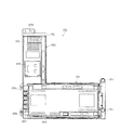
次に、遊技盤30の構成を、図4を用いて説明する。   Next, the configuration of the game board 30 will be described with reference to FIG.

遊技盤30は、その略中央部に設けられた可変表示装置ユニット35と、当該可変表示装置ユニット35を囲むようにして設けられた特別装置としての特別入賞装置401とを備えている。特別入賞装置401の向かって左側方には、第1入球口としての第1契機対応口402が設けられ、特別入賞装置401の向かって右側方には、第2入球口としての第2契機対応口403が設けられている。また、特別入賞装置401の下方、第1契機対応口402の下方、及び第2契機対応口403の下方には一般入賞口31が設けられている。なお、第1契機対応口402及び第2契機対応口403に入球した遊技球は後述する検出スイッチによって検出されるようになっている。   The game board 30 includes a variable display device unit 35 provided at a substantially central portion thereof, and a special winning device 401 as a special device provided so as to surround the variable display device unit 35. A first opportunity corresponding port 402 as a first entrance is provided on the left side of the special winning device 401, and a second entrance as a second entrance is provided on the right side of the special winning device 401. An opportunity corresponding port 403 is provided. In addition, a general winning port 31 is provided below the special winning device 401, below the first opportunity corresponding port 402, and below the second opportunity corresponding port 403. Note that a game ball that has entered the first opportunity corresponding port 402 and the second opportunity corresponding port 403 is detected by a detection switch described later.

特別入賞装置401は、可変表示装置ユニット35の上方において遊技球を特別入賞装置401内へ案内する第1入賞口411と、第1入賞口411を開状態と閉状態とに切り替える第1電動役物412と、可変表示装置ユニット35の下方において特別入賞装置401内に入球した遊技球が入球可能な第2入賞口432と、第2入賞口432を開状態と閉状態とに切り替える第2電動役物431とを備えている。本実施形態では、第2入賞口432に入球があった場合に大当たり状態が発生するよう構成されている。また、第1入賞口411及び第2入賞口432は常には遊技球の入球を困難又は不能とする閉状態(第1の状態)となっており、詳しくは後述するが所定条件が満たされると遊技球の入球が容易な開状態(第2の状態)となる。なお、本実施形態では、第1入賞口411が特別入球部に相当し、第1電動役物412が第1可変入球装置に相当し、第2電動役物431が第2可変入球装置に相当する。また、第2入賞口432が特定領域に相当しており、第2入賞口432への入球が遊技球の特定領域への通過に相当する。   The special winning device 401 has a first winning port 411 for guiding a game ball into the special winning device 401 above the variable display device unit 35, and a first electric combination for switching the first winning port 411 between an open state and a closed state. An object 412, a second winning port 432 in which a game ball that has entered the special winning device 401 below the variable display device unit 35 can enter, and a second winning port 432 that switches between an open state and a closed state. 2 electric accessories 431. In the present embodiment, a big hit state is generated when there is a ball in the second winning opening 432. In addition, the first winning port 411 and the second winning port 432 are always in a closed state (first state) in which it is difficult or impossible to enter a game ball, and as will be described in detail later, a predetermined condition is satisfied. And an open state (second state) in which a game ball can easily enter. In the present embodiment, the first winning opening 411 corresponds to a special pitching portion, the first electric combination 412 corresponds to a first variable pitching device, and the second electric combination 431 is a second variable pitching. It corresponds to a device. Further, the second winning opening 432 corresponds to the specific area, and the ball entering the second winning opening 432 corresponds to the passage of the game ball to the specific area.

また、特別入賞装置401は、第1入賞口411に入賞した遊技球を、第2電動役物431の側上方にまで導く左右ワープ部413、414と、当該左右ワープ部413、414の下方に設けられ、上方に開口する略U字状の下受部415とを備えている。   Further, the special prize winning device 401 has left and right warp portions 413 and 414 for guiding the game balls won in the first winning opening 411 to the upper side of the second electric accessory 431, and below the left and right warp portions 413 and 414. And a substantially U-shaped receiving portion 415 that opens upward.

左右ワープ部413、414は、第1入賞口411の直下方から可変表示装置ユニット35の上肩部を囲むようにして正面略円弧状に形成された左右筒部416、417と、左右筒部416、417の外周側の壁部を延在させるようにして設けられた左右延出部418、419とから構成されている。左ワープ部413と右ワープ部414とは、第1入賞口411の下方、かつ、可変表示装置ユニット35の上方において起点(基端部)を同じくするとともに、可変表示装置ユニット35を挟んで左右対称形状となっており、全体として下方に開口する略円弧状に構成されている。第1入賞口411に入球した遊技球は、左筒部416(右筒部417)に導出され、左延出部418(右延出部419)を経由して下受部415へと導かれる。   The left and right warp portions 413 and 414 are formed in a substantially arcuate front shape so as to surround the upper shoulder portion of the variable display device unit 35 from directly below the first winning opening 411, and the left and right cylinder portions 416, It is comprised from the left-right extension part 418,419 provided so that the wall part of the outer peripheral side of 417 might be extended. The left warp unit 413 and the right warp unit 414 have the same starting point (base end) below the first winning opening 411 and above the variable display device unit 35, and left and right across the variable display device unit 35. It has a symmetric shape and is formed in a substantially arc shape that opens downward as a whole. The game ball that has entered the first winning opening 411 is led out to the left tube portion 416 (right tube portion 417) and guided to the lower receiving portion 415 via the left extension portion 418 (right extension portion 419). It is burned.

また、左右ワープ部413、414には、遊技球を左右ワープ413、414内、すなわち特別入賞装置401内へと案内する入賞開口部421、422が設けられている。入賞開口部421、422は常に開口した状態であるが、その間口幅は遊技球よりも若干幅広な程度であるうえに、遊技球が入賞開口部421、422に入球しにくくなるような遊技盤30面構成(釘配置等)となっている。そのため、入賞開口部421、422に入球することはごく稀である。なお、左延出部418と右延出部419とは、その先端部が互いに向き合うよう構成されるとともに、各先端部に向ってやや下方傾斜するよう構成されている。また、左右延出部418、419においては、遊技球の挙動が視認可能になっている。   The left and right warp portions 413 and 414 are provided with winning openings 421 and 422 for guiding the game balls into the left and right warps 413 and 414, that is, into the special winning device 401. The winning opening portions 421 and 422 are always open, but the width of the opening is slightly wider than the game ball, and the game ball is less likely to enter the winning opening portions 421 and 422. It has a panel 30 surface configuration (nail arrangement, etc.). Therefore, it is very rare to enter the winning openings 421 and 422. Note that the left extending portion 418 and the right extending portion 419 are configured such that the front end portions thereof face each other and are inclined slightly downward toward the respective front end portions. In addition, in the left and right extending portions 418 and 419, the behavior of the game ball is visible.

下受部415は、左右延出部418、419の先端部間の開口を塞ぐようにして設けられている。つまり、特別入賞装置401内は、左右ワープ部413、414と下受部415とで閉塞された領域となっており、特別入賞装置401内へは第1入賞口411、或いは入賞開口部421、422を経由しない限り入球できないようになっている。   The lower receiving portion 415 is provided so as to close the opening between the distal end portions of the left and right extending portions 418 and 419. That is, the special winning device 401 is an area closed by the left and right warp units 413 and 414 and the lower receiving unit 415, and the special winning device 401 has a first winning port 411 or a winning opening 421, You can't enter the ball without going through 422.

第2電動役物431と第2入賞口432とは、下受部415の内側において上下に並ぶようにして設けられている。また、下受部415の内側下端部に隣接して特定入賞口433が設けられている。特別入賞装置401内に入球した遊技球は、特定入賞口433又は第2入賞口432のどちらかに入賞するようになっている。   The second electric accessory 431 and the second winning opening 432 are provided so as to be lined up and down inside the lower receiving portion 415. In addition, a specific winning opening 433 is provided adjacent to the inner bottom end of the lower receiving portion 415. The game balls that have entered the special prize winning device 401 are designed to win either the special prize opening 433 or the second prize opening 432.

第2電動役物431は、上下に貫通する入賞路434と、当該入賞路434を開状態と閉状態とに切り替える一対の可動羽435とを備えている。また、第2電動役物431の下端部には、第2入賞口432への入球を規制する袴状の入賞規制部436が設けられている。   The second electric accessory 431 includes a winning path 434 penetrating vertically and a pair of movable wings 435 for switching the winning path 434 between an open state and a closed state. In addition, a bowl-shaped winning restriction part 436 that restricts the entry into the second winning opening 432 is provided at the lower end of the second electric accessory 431.

第2入賞口432は、上方に開口した略U字状の球受441の内側に設けられている。球受441は前記入賞路434の直下方に配設されており、入賞路434を通過した遊技球は必ず球受441内に至り、第2入賞口432へと入球するようになっている。つまり、第2電動役物431(可動羽435)が作動して入賞路434が開状態とされると、遊技球が第2入賞口432に入賞しやすい状態となる。一方、入賞路434を通過しない遊技球は、第2電動役物431の入賞規制部436によって、第2入賞口432に入球できないよう構成されている。また、第2電動役物431については閉状態となっているときでも、一対の可動羽435間に遊技球がぎりぎり通過できるだけの間隔が残されているため遊技球が入賞路434に全く入球できないわけではないが、第2電動役物431が閉状態のときに遊技球が入賞路434に入球し、第2入賞口432に入賞することはごく稀である。   The second winning opening 432 is provided inside a substantially U-shaped ball receiver 441 that opens upward. The ball receiver 441 is disposed immediately below the winning path 434, and the game ball that has passed through the winning path 434 always reaches the ball receiver 441 and enters the second winning port 432. . That is, when the second electric accessory 431 (movable wing 435) is operated and the winning path 434 is opened, the game ball is likely to win the second winning opening 432. On the other hand, a game ball that does not pass through the winning path 434 is configured not to enter the second winning opening 432 by the winning restriction portion 436 of the second electric accessory 431. Further, even when the second electric accessory 431 is in the closed state, there is a space left between the pair of movable wings 435 so that the game ball can pass through the ball, so that the game ball enters the winning path 434 at all. Although it is not impossible, it is rare that a game ball enters the winning path 434 and wins the second winning opening 432 when the second electric accessory 431 is in the closed state.

球受441の内周側には、第2入賞口432の上方に位置するようにして、遊技盤30面に対し出没可能なVストッパー442が設けられている。Vストッパー442は、遊技盤30の背面側に設けられたVソレノイド443と接続されている(図8参照)。Vソレノイド443が非励磁状態のときには、Vストッパー442の前端部と遊技盤30面とが面一となり、球受441内に入球した遊技球の第2入賞口432への入賞が許容されるようになっている。一方、Vソレノイド443が励磁状態とされると、Vストッパー442が遊技盤30面から突出し、第2入賞口432への入賞が規制されるとともに、Vストッパー442上において遊技球が1球だけ停留されるようになっている。つまり、球受441内に遊技球が保留されることとなる。また、Vストッパー442上において遊技球が既に1球保留されている場合、入賞路434を通過してきた遊技球は、前記保留されている遊技球によってはじかれて球受441の側方に落下し、特定入賞口433に入賞することとなる。   On the inner peripheral side of the ball receiver 441, a V stopper 442 that can be moved in and out with respect to the surface of the game board 30 is provided so as to be positioned above the second winning opening 432. The V stopper 442 is connected to a V solenoid 443 provided on the back side of the game board 30 (see FIG. 8). When the V solenoid 443 is in a non-excited state, the front end portion of the V stopper 442 and the surface of the game board 30 are flush with each other, and a game ball that has entered the ball receiver 441 is allowed to enter the second winning port 432. It is like that. On the other hand, when the V solenoid 443 is energized, the V stopper 442 protrudes from the surface of the game board 30 and the winning to the second winning opening 432 is restricted, and only one game ball is stopped on the V stopper 442. It has come to be. That is, the game ball is put on hold in the ball receiver 441. If one game ball is already held on the V stopper 442, the game ball passing through the winning path 434 is repelled by the held game ball and falls to the side of the ball receiver 441. The specific winning opening 433 will be won.

可変表示装置ユニット35は、液晶表示装置たる可変表示装置42を備えており、後述する表示制御装置45により表示内容が制御される。可変表示装置42の表示部は、通常、図38に示すように、第1表示部42L及び第2表示部42Rの2つの表示部に区画されており、各表示部においてそれぞれ図柄が変動表示される。本実施形態では、第1表示部42Lにおいて識別情報としての第1図柄が表示され、第2表示部42Rにおいて識別情報としての第2図柄が表示されるようになっている。可変表示装置42は、第1契機対応口402への入球をトリガとして第1図柄を変動表示するとともに、第2契機対応口403への入球をトリガとして第2図柄を変動表示するよう構成されている。なお、本実施形態では、表示制御装置45が第1表示制御手段及び第2表示制御手段に相当する。
また、第1表示部42Lが第1可変表示手段に相当し、第2表示部42Rが第2可変表示手段に相当する。
The variable display device unit 35 includes a variable display device 42 which is a liquid crystal display device, and display contents are controlled by a display control device 45 which will be described later. As shown in FIG. 38, the display unit of the variable display device 42 is usually divided into two display units, a first display unit 42L and a second display unit 42R, and the symbols are variably displayed on each display unit. The In the present embodiment, the first symbol as identification information is displayed on the first display unit 42L, and the second symbol as identification information is displayed on the second display unit 42R. The variable display device 42 is configured to variably display the first symbol using a ball entering the first opportunity corresponding port 402 as a trigger and to variably display the second symbol using a ball entering the second trigger corresponding port 403 as a trigger. Has been. In the present embodiment, the display control device 45 corresponds to a first display control unit and a second display control unit.
The first display portion 42L corresponds to the first variable display means, and the second display portion 42R corresponds to the second variable display means.

第1表示部42Lには上、中、下の3つの図柄列が表示される。各図柄列は複数の第1図柄によって構成されており、これら第1図柄が図柄列毎にスクロールされるようにして第1表示部42Lに可変表示(変動表示)されるようになっている。第1図柄には「0」〜「9」の数字が各々付されるよう構成されており、図柄列毎に周期性をもって第1図柄が右から左へと変動表示されるようになっている。この場合において、上図柄列→下図柄列→中図柄列の順に変動表示が停止し、その停止時に第1表示部42L上で第1図柄が当選となる組合せで停止すれば第1表示部42Lにおいて当選表示が行われるようになっている。本実施形態では、上・中・下図柄列に同一の第1図柄が表示された場合に当選となり、その時に表示された3つ並びの第1図柄の組み合わせ(いわゆるゾロ目)が当選図柄である(図38(c)参照)。このように、第1図柄が当選図柄で確定停止表示された場合には第1電動役物412が作動させられ、第1入賞口411が開放される。そして、開放された第1入賞口411に遊技球を入賞させることで、当該遊技球を特別入賞装置401内に入球させることができる。   The first display portion 42L displays three symbol rows, upper, middle, and lower. Each symbol row is composed of a plurality of first symbols, and these first symbols are variably displayed (variable display) on the first display section 42L so as to be scrolled for each symbol row. The first symbol is configured to be numbered from “0” to “9”, and the first symbol is displayed in a variable manner from right to left with periodicity for each symbol row. . In this case, the variable display stops in the order of the upper symbol row → the lower symbol row → the middle symbol row, and if the first symbol stops on the first display portion 42L at the time of the stop, the first display portion 42L The winning display is made at. In this embodiment, when the same first symbol is displayed in the upper, middle, and lower symbol rows, the winning combination is obtained, and the combination of the first three symbols displayed at that time (so-called doublet) is the winning symbol. Yes (see FIG. 38 (c)). As described above, when the first symbol is confirmed and stopped in the winning symbol, the first electric accessory 412 is activated and the first winning opening 411 is opened. Then, the game ball can be entered into the special prize-winning device 401 by winning the game ball in the opened first prize opening 411.

一方、第2表示部42Rにおいては、第2表示部42Rに左、中、右の3つの図柄列が表示される(図38(c)参照)。各図柄列は複数の第2図柄によって構成されており、これら第2図柄が図柄列毎にスクロールされるようにして第2表示部42Rに可変表示(変動表示)されるようになっている。第2図柄には「0」〜「9」の数字が各々付されるよう構成されており、図柄列毎に周期性をもって第2図柄が上から下へと変動表示されるようになっている。この場合において、左図柄列→右図柄列→中図柄列の順に変動表示が停止し、その停止時に第2表示部42R上で第2図柄が当選となる組合せで停止すれば第2表示部42Rにおいて当選表示が行われるようになっている。本実施形態では、左・中・右図柄列に同一の第2図柄が表示された場合に当選となり、その時に表示された3つ並びの第2図柄の組み合わせ(いわゆるゾロ目)が当選図柄である。このように、第2図柄が当選図柄で確定停止表示された場合には、第2電動役物431が作動させられて入賞路434が開放され、遊技球が第2入賞口432に入賞しやすい状態となる。   On the other hand, in the second display portion 42R, three symbol strings of left, middle, and right are displayed on the second display portion 42R (see FIG. 38C). Each symbol row is composed of a plurality of second symbols, and these second symbols are scrolled for each symbol row and are variably displayed (variable display) on the second display unit 42R. The second symbol is configured so that numbers “0” to “9” are attached thereto, and the second symbol is variably displayed from top to bottom with periodicity for each symbol row. . In this case, the variable display stops in the order of the left symbol row → the right symbol row → the middle symbol row, and if the second symbol is stopped on the second display portion 42R in the winning combination at that time, the second display portion 42R. The winning display is made at. In this embodiment, when the same second symbol is displayed in the left, middle, and right symbol rows, the winning combination is obtained, and the combination of the three symbols arranged at that time (so-called doublet) is the winning symbol. is there. As described above, when the second symbol is displayed as a winning symbol in the winning symbol, the second electric accessory 431 is operated to open the winning path 434 so that the game ball can easily win the second winning opening 432. It becomes a state.

特に本実施形態では、通常時において、第2入賞口432に入賞があると大当たり状態が発生させられる。すなわち、第2入賞口432に入賞があると、可変表示装置42において大当たり状態であることを示す特別遊技動画が表示され、大当たり状態が開始される。大当たり状態においては、所定時間の経過又は所定個数の第1入賞口411への入賞を1ラウンドとして、第1入賞口411が所定回数(所定ラウンド数)繰り返し開放される。ただし、各ラウンド毎に第2入賞口432への入賞があることが、ラウンド継続の必要条件とされている。   In particular, in the present embodiment, in a normal state, if there is a winning in the second winning opening 432, a big hit state is generated. In other words, when there is a winning at the second winning opening 432, a special game moving image indicating that the jackpot state is displayed on the variable display device 42, and the jackpot state is started. In the big hit state, the first winning port 411 is repeatedly opened a predetermined number of times (predetermined number of rounds) with the passage of a predetermined time or the winning of the predetermined number of first winning ports 411 as one round. However, it is a necessary condition for the continuation of the round that there is a winning in the second winning opening 432 for each round.

また、本実施形態では、第1表示部42Lと第2表示部42Rとに個別に対応するようにして、保留記憶手段としての保留ランプ46Lと保留ランプ46Rとが設けられている。詳しくは、第1図柄の変動表示中(第2図柄変動中)に、新たに遊技球が第1契機対応口402(第2契機対応口403)に入球した場合には、その分の第1図柄(第2図柄)の変動表示は、その時点で行われている変動表示の終了後に行われる構成となっている。つまり、変動表示が待機(保留)されることとなる。この保留される変動表示の最大回数は、パチンコ機の機種毎に決められているが、本実施形態ではそれぞれ4回まで保留され、その保留回数が保留ランプ46L、46Rにて点灯表示されるようになっている。   In the present embodiment, a holding lamp 46L and a holding lamp 46R are provided as holding storage means so as to individually correspond to the first display section 42L and the second display section 42R. Specifically, when a game ball newly enters the first opportunity corresponding port 402 (second trigger corresponding port 403) while the first symbol variation is being displayed (during the second symbol variation), The variation display of one symbol (the second symbol) is performed after the variation display performed at that time ends. That is, the variable display is on standby (held). The maximum number of the variable display to be held is determined for each model of the pachinko machine, but in this embodiment, the variable display is held up to 4 times, and the number of hold times is lit and displayed by the holding lamps 46L and 46R. It has become.

本実施形態では、第1表示部42L、第2表示部42R毎に、それぞれの保留分が最大保留回数に達するまでカウントされるようになっている。かかる図柄変動表示の保留数は、図示しない保留カウンタによってカウント及び記憶される。以下、保留カウンタに記憶されている保留数を始動保留球数Nと称する。さらに本実施形態では、第1表示部42L、第2表示部42R毎に保留数がカウントされるよう構成されているため、第1表示部42Lに対応する始動保留球数を始動保留球数NL、第2表示部42Rに対応する始動保留球数を始動保留球数NRと称することとする。   In the present embodiment, for each of the first display part 42L and the second display part 42R, each hold is counted until reaching the maximum number of holds. The number of holds of the symbol variation display is counted and stored by a hold counter (not shown). Hereinafter, the number of holdings stored in the holding counter is referred to as a starting holding ball number N. Furthermore, in this embodiment, since the number of holdings is counted for each of the first display unit 42L and the second display unit 42R, the number of starting reserved balls corresponding to the first display unit 42L is set as the number of starting reserved balls NL. The number of starting reserved balls corresponding to the second display portion 42R will be referred to as a starting reserved ball number NR.

さて、詳しくは後述するが、本実施形態では、保留ランプ46Lにおいて、当選となる変動表示が保留されているか否かが点灯態様にて示唆(教示)可能に構成されている。基本的に、保留ランプ46Lは、変動表示が保留されていないときには消灯され、変動表示が保留されているときには保留されている変動表示の数だけ点灯されるのであるが、本実施形態では、保留されている変動表示の内容(当選するか否か)によって保留ランプ46Lの点灯色が異なるようになっている。保留ランプ46Lは、最大保留数(本実施形態では4つ)に区分けされた領域にそれぞれ赤色LEDと青色LEDとを具備しており、各LEDが適宜点灯・消灯されることで前記各領域の点灯色が変化するようになっている。   As will be described in detail later, in the present embodiment, the hold lamp 46L is configured to suggest (teach) whether or not the winning variation display is held in a lighting manner. Basically, the hold lamp 46L is turned off when the variable display is not held, and is turned on for the number of the variable displays held when the variable display is held. The lighting color of the holding lamp 46L differs depending on the contents of the displayed variable display (whether or not to win). The holding lamp 46L includes a red LED and a blue LED in regions divided into the maximum number of holdings (four in this embodiment), and each LED is appropriately turned on / off so that The lighting color changes.

その他に、遊技盤30にはアウト口36が設けられており、各種入賞口等に入球しなかった遊技球はこのアウト口36を通って図示しない球排出路の方へと案内されるようになっている。遊技盤30には、遊技球の落下方向を適宜分散、調整等するために多数の釘が植設されているとともに、風車等の各種部材(役物)が配設されている。なお、可変表示装置ユニット35や特別入賞装置401は、ルータ加工によって形成された貫通孔に配設され、遊技盤30前面側から木ネジ等により取付けられている。一般入賞口31や特定入賞口433に遊技球が入賞した場合、後述する検出スイッチの出力により、上皿19(または下皿15)へ所定数の賞品球が払い出される。本実施形態では、一般入賞口31への入賞があった場合には5球払い出され、第2入賞口432及び特定入賞口433への入賞があった場合には10球払い出されるようになっている。   In addition, the game board 30 is provided with an out port 36, so that game balls that have not entered the various winning ports etc. are guided through the out port 36 toward a ball discharge path (not shown). It has become. A number of nails are planted on the game board 30 in order to appropriately disperse and adjust the falling direction of the game balls, and various members (instruments) such as a windmill are arranged. The variable display device unit 35 and the special prize-winning device 401 are disposed in through holes formed by router processing, and are attached from the front side of the game board 30 with wood screws or the like. When a game ball is won in the general winning opening 31 or the specific winning opening 433, a predetermined number of prize balls are paid out to the upper plate 19 (or the lower plate 15) by the output of a detection switch described later. In the present embodiment, 5 balls are paid out when there is a prize at the general prize opening 31, and 10 balls are paid out when there is a prize at the second prize opening 432 and the specific prize opening 433. ing.

また、遊技盤30には、遊技球発射装置から発射された遊技球を遊技盤30上部へ案内するためのレールユニット50が取り付けられており、ハンドル18の回動操作に伴い発射された遊技球はレールユニット50を通じて所定の遊技領域に案内されるようになっている。レールユニット50はリング状をなす樹脂成形品にて構成されており、内外二重に一体形成された内レール構成部(内レール部)51と外レール構成部(外レール取付け部)52とを有する。内レール構成部51は上方の約1/4ほどを除いて略円環状に形成されている。また、一部(主に左側部)が内レール構成部51に向かい合うようにして外レール構成部52が形成されている。かかる場合、内レール構成部51と外レール構成部52とにより主として誘導レールが構成され、これら各レール構成部51,52が所定間隔を隔てて並行する部分(向かって左側の部分)により球案内通路が形成されている。なお、球案内通路は、遊技盤30との当接面を有した溝状、すなわち手前側を開放した溝状に形成されている。   Further, the game board 30 is provided with a rail unit 50 for guiding the game balls launched from the game ball launching device to the upper part of the game board 30, and the game balls launched by the turning operation of the handle 18. Are guided to a predetermined game area through the rail unit 50. The rail unit 50 is formed of a ring-shaped resin molded product, and includes an inner rail constituent part (inner rail part) 51 and an outer rail constituent part (outer rail mounting part) 52 that are integrally formed in an inner and outer double. Have. The inner rail constituting portion 51 is formed in a substantially annular shape except for about 1/4 of the upper portion. Further, the outer rail constituting portion 52 is formed so that a part (mainly the left side portion) faces the inner rail constituting portion 51. In such a case, the inner rail constituting portion 51 and the outer rail constituting portion 52 mainly constitute a guide rail, and each of the rail constituting portions 51 and 52 is guided by a ball by a portion (left portion toward the left) that is parallel with a predetermined interval. A passage is formed. The ball guide passage is formed in a groove shape having a contact surface with the game board 30, that is, a groove shape in which the front side is opened.

内レール構成部51の先端部分(図4の左上部)には戻り球防止部材53が取着されている。これにより、一旦、内レール構成部51及び外レール構成部52間の球案内通路から遊技盤30の上部へと案内された遊技球が再度球案内通路内に戻ってしまうといった事態が防止されるようになっている。また、外レール構成部52には、遊技球の最大飛翔部分に対応する位置(図4の右上部:外レール構成部52の先端部に相当する部位)に返しゴム54が取着されている。従って、所定以上の勢いで発射された遊技球は、返しゴム54に当たって例えば遊技盤30の略中央部側へ戻される。外レール構成部52の内側面には、遊技球の飛翔をより滑らかなものとするべく、長尺状をなすステンレス製の摺動プレート55が取着されている。なお、本実施形態では、外レール構成部52及び摺動プレート55によって、いわゆる従来の外レールに相当するものが構成されている。そして、内外レール構成部51,52及び摺動プレート55をレールユニット50としてユニット化することにより、従来の内外レールを別々に設けた構成に比べて、取付け作業が容易となり作業性が向上する。   A return ball preventing member 53 is attached to the tip portion of the inner rail constituting portion 51 (the upper left portion in FIG. 4). This prevents a situation in which the game ball once guided from the ball guide passage between the inner rail constituting portion 51 and the outer rail constituting portion 52 to the upper portion of the game board 30 returns to the ball guide passage again. It is like that. Further, a return rubber 54 is attached to the outer rail constituting portion 52 at a position corresponding to the maximum flight portion of the game ball (upper right portion in FIG. 4: a portion corresponding to the tip portion of the outer rail constituting portion 52). . Therefore, the game ball launched at a predetermined momentum or more hits the return rubber 54 and is returned to, for example, the substantially central portion side of the game board 30. A long stainless steel sliding plate 55 is attached to the inner side surface of the outer rail constituting portion 52 in order to make the flight of the game ball smoother. In the present embodiment, the outer rail constituting portion 52 and the sliding plate 55 constitute a so-called conventional outer rail. Then, by making the inner and outer rail components 51 and 52 and the sliding plate 55 into a unit as the rail unit 50, the mounting operation becomes easier and the workability is improved as compared with the conventional configuration in which the inner and outer rails are separately provided.

また、レールユニット50の外周部には、外方へ張り出した円弧状のフランジ56が形成されている。フランジ56は、遊技盤30に対する取付面を構成する。レールユニット50が遊技盤30に取り付けられる際には、遊技盤30上にフランジ56が当接され、その状態で、当該フランジ56に形成された複数の透孔にネジ等の固定手段が挿通されて遊技盤30に対するレールユニット50の締結がなれるようになっている。さらに本実施形態では、正面から見てレールユニット50の上下左右の各端部は略直線状に(平坦に)形成されている。つまり、レールユニット50の上下左右の各端部においてはフランジ56が切り落とされ、パチンコ機10における有限の領域にてレール径の拡張、すなわち遊技盤30上の遊技領域の拡張が図られるようになっている。なお、左下のフランジ56においては他の部分(左上部,右上部及び右下部のフランジ56)と比較して、より多く固定手段が使用されている。これは、上記誘導レール及び球案内通路の位置をより適正な位置に固定するためであり、これにより遊技球発射装置から発射された遊技球がより安定して遊技盤30上部へ案内される。加えて、固定手段の数を増やすことでレールユニット50をより強固に固定でき、仮にレールユニット50の成形時において歪みが生じたとしても、その歪みを吸収する効果がある。   An arc-shaped flange 56 projecting outward is formed on the outer peripheral portion of the rail unit 50. The flange 56 constitutes a mounting surface for the game board 30. When the rail unit 50 is attached to the game board 30, the flange 56 is brought into contact with the game board 30, and in this state, fixing means such as screws are inserted into the plurality of through holes formed in the flange 56. Thus, the rail unit 50 can be fastened to the game board 30. Further, in the present embodiment, the top, bottom, left, and right ends of the rail unit 50 are formed substantially linearly (flatly) when viewed from the front. That is, the flange 56 is cut off at each of the upper, lower, left, and right ends of the rail unit 50, so that the rail diameter can be expanded in a limited area in the pachinko machine 10, that is, the game area on the game board 30 can be expanded. ing. The lower left flange 56 uses more fixing means than the other parts (upper left, upper right and lower right flanges 56). This is for fixing the positions of the guide rail and the ball guide passage to more appropriate positions, whereby the game ball launched from the game ball launching device is more stably guided to the upper part of the game board 30. In addition, the rail unit 50 can be more firmly fixed by increasing the number of fixing means, and even if distortion occurs when the rail unit 50 is molded, there is an effect of absorbing the distortion.

内レール構成部51及び外レール構成部52間の球案内通路の入口には、同球案内通路の一部を閉鎖するようにして凸部57が形成されている。この凸部57は、内レール構成部51からレールユニット50下端部にかけて略鉛直方向に設けられ、遊技領域まで至らず球案内通路内を逆流してくるファール球をファール球通路63(図3参照)に導くための役目をなす。なお、遊技盤30の右下隅部及び左下隅部は、証紙等のシールやプレート(図4のS1,S2)を貼着するためのスペースとなっており、この貼着スペースを確保するために、フランジ56に切欠58,59が形成されている。   A convex portion 57 is formed at the entrance of the spherical guide passage between the inner rail constituting portion 51 and the outer rail constituting portion 52 so as to close a part of the spherical guide passage. This convex portion 57 is provided in a substantially vertical direction from the inner rail constituting portion 51 to the lower end portion of the rail unit 50, and a foul ball that does not reach the game area and flows backward in the ball guide passage is used as a foul ball passage 63 (see FIG. 3). ). Note that the lower right corner and the lower left corner of the game board 30 are spaces for attaching seals and plates (S1, S2 in FIG. 4) such as certificate stamps, etc., in order to secure this attachment space. The notches 58 and 59 are formed in the flange 56.

次に、遊技領域について説明する。遊技領域は、レールユニット50の内周部(内外レール構成部51,52)により略円形状に区画形成されており、特に本実施形態では、遊技盤30の盤面上に区画される遊技領域が従来よりもはるかに大きく構成されている。本実施形態では、外レール構成部52の最上部地点から遊技盤30下部までの間の距離は445mm(従来品よりも58mm長い)、外レール構成部52の極左位置から内レール構成部51の極右位置までの間の距離は435mm(従来品よりも50mm長い)となっている。また、内レール構成部51の極左位置から内レール構成部51の極右位置までの間の距離は418mmとなっている。   Next, the game area will be described. The game area is partitioned and formed in a substantially circular shape by the inner periphery (inner and outer rail components 51 and 52) of the rail unit 50. In particular, in this embodiment, the game area partitioned on the board surface of the game board 30 is It is much larger than before. In the present embodiment, the distance from the uppermost point of the outer rail component 52 to the lower part of the game board 30 is 445 mm (58 mm longer than the conventional product), and from the extreme left position of the outer rail component 52 to the inner rail component 51. The distance to the extreme right position is 435 mm (50 mm longer than the conventional product). The distance from the extreme left position of the inner rail component 51 to the extreme right position of the inner rail component 51 is 418 mm.

本実施形態では、遊技領域を、パチンコ機10の正面から見て、内レール構成部51及び外レール構成部52によって囲まれる領域のうち、内外レール構成部51,52の並行部分である誘導レールの領域を除いた領域としている。従って、遊技領域と言った場合には誘導レール部分は含まないため、遊技領域の向かって左側限界位置は外レール構成部52によってではなく内レール構成部51によって特定される。同様に、遊技領域の向かって右側限界位置は内レール構成部51によって特定される。また、遊技領域の下側限界位置は遊技盤30の下端位置によって特定される。また、遊技領域の上側限界位置は外レール構成部52によって特定される。   In this embodiment, the game area is a guide rail that is a parallel part of the inner and outer rail constituting parts 51 and 52 in the area surrounded by the inner rail constituting part 51 and the outer rail constituting part 52 when viewed from the front of the pachinko machine 10. This area is excluded from the above area. Therefore, since the game area does not include the guide rail portion, the left limit position toward the game area is specified not by the outer rail component 52 but by the inner rail component 51. Similarly, the right limit position toward the game area is specified by the inner rail constituting unit 51. The lower limit position of the game area is specified by the lower end position of the game board 30. Further, the upper limit position of the game area is specified by the outer rail component 52.

従って、本実施形態では、遊技領域の幅(左右方向の最大幅)は、418mmであり、遊技領域の高さ(上下方向の最大幅)は、445mmである。   Therefore, in the present embodiment, the width of the game area (maximum width in the left-right direction) is 418 mm, and the height of the game area (maximum width in the vertical direction) is 445 mm.

ここで、前記遊技領域の幅は、少なくとも380mm以上あることが望ましい。より好ましくは390mm以上、400mm以上、410mm以上、420mm以上、430mm以上、440mm以上、450mm以上、さらに460mm以上であることが望ましい。もちろん、470mm以上であってもよい。すなわち、遊技領域の幅は、遊技領域拡大という観点からは大きい程好ましい。また、遊技領域の高さは、少なくとも400mm以上あることが望ましい。より好ましくは410mm以上、420mm以上、430mm以上、440mm以上、450mm以上、さらには460mm以上であることがより望ましい。もちろん、470mm以上、480mm以上、490mm以上としてもよい。すなわち、遊技領域の幅は、遊技領域拡大という観点からは大きい程好ましい。なお、上記幅及び高さの組合せについては、上記数値を任意に組み合わせたものとしてもよい。   Here, the width of the gaming area is preferably at least 380 mm. More preferably, it is 390 mm or more, 400 mm or more, 410 mm or more, 420 mm or more, 430 mm or more, 440 mm or more, 450 mm or more, and further 460 mm or more. Of course, it may be 470 mm or more. That is, the width of the game area is preferably as large as possible from the viewpoint of expanding the game area. The height of the game area is preferably at least 400 mm. More preferably, it is 410 mm or more, 420 mm or more, 430 mm or more, 440 mm or more, 450 mm or more, and more preferably 460 mm or more. Of course, it is good also as 470 mm or more, 480 mm or more, and 490 mm or more. That is, the width of the game area is preferably as large as possible from the viewpoint of expanding the game area. In addition, about the combination of the said width | variety and height, it is good also as what combined the said numerical value arbitrarily.

本実施形態では、遊技盤30面に対する遊技領域の面積の比率は約70%と、従来に比べ格段に面積比が大きいものとなっている。なお、遊技盤30面に対する遊技領域の面積比は、従来では50%程度に過ぎなかったことから、遊技盤30を共通とした前提においてはかなり遊技領域を拡大しているといえる。尚、パチンコ機10の外形は遊技場への設置の都合上製造者間でほぼ統一されており、遊技盤30の大きさも同様とせざるを得ない状況下において、上記のように遊技盤30面に対する遊技領域の面積の比率を約20%も高めたことは、遊技領域拡大の観点で非常に有意義である。ここで、前記比率は、少なくとも60%以上であることが望ましい。さらに好ましくは65%以上であり、より好ましくは70%以上である。また、本実施形態の場合を越えて75%以上であれば、一層望ましい。さらには、80%以上であってもよい。   In the present embodiment, the ratio of the area of the game area to the surface of the game board 30 is about 70%, which is a much larger area ratio than before. Note that the area ratio of the game area to the surface of the game board 30 has been only about 50% in the past, so it can be said that the game area is considerably expanded on the premise that the game board 30 is shared. It should be noted that the external shape of the pachinko machine 10 is almost uniform among manufacturers for the convenience of installation in the game hall, and in the situation where the size of the game board 30 must be the same, the surface of the game board 30 as described above. Increasing the ratio of the area of the gaming area to about 20% is very significant from the viewpoint of expanding the gaming area. Here, the ratio is preferably at least 60% or more. More preferably, it is 65% or more, More preferably, it is 70% or more. Further, if it is 75% or more exceeding the case of this embodiment, it is more desirable. Furthermore, it may be 80% or more.

また、パチンコ機10全体の正面側の面積に対する遊技領域の面積の比率は約40%と、従来に比べ格段に面積比が大きいものとなっている。なお、パチンコ機10全体の正面側の面積に対する遊技領域の面積比は、35パーセント以上であるのが望ましい。もちろん、40パーセント以上としてもよいし、45パーセント以上、又は50パーセント以上としてもよい。   Further, the ratio of the area of the game area to the area of the front side of the entire pachinko machine 10 is about 40%, which is a much larger area ratio than in the past. The area ratio of the game area to the area of the front side of the entire pachinko machine 10 is desirably 35% or more. Of course, it may be 40% or more, 45% or more, or 50% or more.

なお、遊技領域が左右方向に拡張されていることによって、風車、複数の釘(遊技球を中央に誘導するための誘導釘)、他の役物を種々配設することができ、可変表示装置ユニット35の左右両側の遊技領域での遊技球の挙動を一層面白くすることができるようになっている。また、遊技領域が上下方向にも拡張されていることから、さらに風車、複数の釘、他の役物を種々配設することができ、遊技領域での上下方向の遊技球の挙動をより一層面白くすることができるようになっている。   In addition, by extending the game area in the left-right direction, a windmill, a plurality of nails (guide nails for guiding a game ball to the center), and other accessories can be arranged in various ways. The behavior of the game ball in the game areas on the left and right sides of the unit 35 can be made more interesting. In addition, since the game area is also expanded in the vertical direction, it is possible to further arrange various windmills, a plurality of nails, and other accessories, thereby further improving the behavior of the game balls in the vertical direction in the game area. It can be interesting.

図3の説明に戻り、前記樹脂ベース20において、窓孔21(遊技盤30)の下方には、遊技球発射装置より発射された直後に遊技球を案内するための発射レール61が取り付けられている。発射レール61は、その後方の金属板62と一体的に樹脂ベース20に取付固定されており、所定の発射角度(打ち出し角度)にて直線的に延びるよう構成されている。従って、ハンドル18の回動操作に伴い発射された遊技球は、まずは発射レール61に沿って斜め上方に打ち出され、その後前述した通りレールユニット50の球案内通路を通じて所定の遊技領域に案内されるようになっている。   Returning to the description of FIG. 3, in the resin base 20, below the window hole 21 (game board 30), a launch rail 61 for guiding the game ball immediately after being launched from the game ball launcher is attached. Yes. The firing rail 61 is fixedly attached to the resin base 20 integrally with the metal plate 62 behind the firing rail 61, and is configured to extend linearly at a predetermined firing angle (launch angle). Accordingly, the game ball that is launched in accordance with the turning operation of the handle 18 is first launched obliquely upward along the launch rail 61 and then guided to a predetermined game area through the ball guide passage of the rail unit 50 as described above. It is like that.

本パチンコ機10の場合、遊技領域が従来よりも大幅に拡張されることは既に述べたが、かかる構成下では、誘導レールの曲率を小さくせざるを得ないことから、打出球を安定化させるための工夫を要する。そこで本実施形態では、遊技球の発射位置を低くするとともに発射レール61の傾斜角度(発射角度)を既存のものよりも幾分大きくし(すなわち発射レール61を立ち上げるようにし)、さらに発射レール61の長さを既存のものよりも長くして十分な長さの球誘導距離を確保するようにしている。これにより、遊技球発射装置から発射された遊技球をより安定した状態で誘導レールに案内できるようにしている。この場合特に、発射レール61を、遊技球発射装置の発射位置から遊技領域の中央位置(アウト口36)を越える位置まで延びるよう形成している。また、発射レール61を上記構成とするため、本実施形態では金属板62も従来のものより比較的大きなものとし、それを固定する固定手段の数も従来に比べ多くしている。   In the case of this pachinko machine 10, it has already been described that the game area is greatly expanded compared to the conventional case, but under such a configuration, the curvature of the guide rail must be reduced, so that the launch ball is stabilized. Need some ingenuity. Therefore, in the present embodiment, the launch position of the game ball is lowered, the inclination angle (launch angle) of the launch rail 61 is made somewhat larger than the existing one (that is, the launch rail 61 is raised), and the launch rail is further increased. The length of 61 is made longer than the existing one so as to ensure a sufficiently long ball guiding distance. Thereby, the game ball launched from the game ball launching device can be guided to the guide rail in a more stable state. Particularly in this case, the launch rail 61 is formed so as to extend from the launch position of the game ball launcher to a position beyond the center position (out port 36) of the game area. In addition, since the launch rail 61 has the above-described configuration, in this embodiment, the metal plate 62 is also relatively larger than the conventional one, and the number of fixing means for fixing the metal plate 62 is larger than the conventional one.

また、発射レール61とレールユニット50(誘導レール)との間には所定間隔の隙間があり、この隙間より下方にファール球通路63が形成されている。従って、仮に、遊技球発射装置から発射された遊技球が戻り球防止部材53まで至らずファール球として誘導レール内を逆戻りする場合には、そのファール球がファール球通路63を介して下皿15に排出される。因みに、本実施形態の場合、発射レール61の長さは約240mm、発射レール先端部の隙間の長さ(発射レール61の延長線上の長さ)は約40mmである。   Further, there is a gap of a predetermined interval between the firing rail 61 and the rail unit 50 (guidance rail), and a foul ball passage 63 is formed below the gap. Therefore, if the game ball fired from the game ball launching device does not reach the return ball prevention member 53 and returns to the inside of the guide rail as a foul ball, the foul ball passes through the foul ball passage 63 to the lower plate 15. To be discharged. Incidentally, in the case of the present embodiment, the length of the firing rail 61 is about 240 mm, and the length of the gap at the tip of the firing rail (the length on the extension line of the firing rail 61) is about 40 mm.

ファール球が誘導レール内を逆流してくる際、その多くは外レール構成部52に沿って流れ、外レール構成部52の下端部に到達した時点で下方に落下するが、一部のファール球は誘導レール内で暴れ、内レール構成部51側へ跳ね上がるものもある。この際、跳ね上がったファール球は、球案内通路入口の前記凸部57に当たり、ファール球通路63に誘導される。これにより、ファール球の全てがファール球通路63に確実に案内されるようになる。これにより、ファール球と次に発射される遊技球との干渉が抑制される。   When the foul sphere flows backward in the guide rail, most of the foul sphere flows along the outer rail constituting portion 52 and drops downward when reaching the lower end portion of the outer rail constituting portion 52. May be ramped in the guide rail and jump to the inner rail component 51 side. At this time, the splashed foul ball hits the convex portion 57 at the entrance of the ball guide passage and is guided to the foul ball passage 63. Thereby, all of the foul balls are surely guided to the foul ball passage 63. This suppresses interference between the foul ball and the next game ball to be launched.

なお、詳しい図面の開示は省略するが、遊技球発射装置には、前面枠セット14側の球出口(上皿19の最下流部より通じる球出口)から遊技球が1つずつ供給される。この際、本実施形態では遊技球の発射位置を低くしたため、前面枠セット14側の球出口から前記発射位置への落差が大きくなるが、発射レール61の基端部付近にはその右側と手前側にそれぞれガイド部材65,66を設置している。これにより、前面枠セット14側の球出口から供給される遊技球が常に所定の発射位置にセットされ、安定した発射動作が実現できる。また、遊技球発射装置には打球槌が設けられ、軸部を中心とする打球槌の回動に伴い遊技球が発射されるが、打球槌に関して軽量化が望まれている。それ故、アルミニウム等の軽金属への材料変更や軸部寸法の縮小化により打球槌の軽量化を図る一方で、十分な発射力を確保すべく、打球槌のヘッド部(軸部と反対側の端部)に重り部を設けている。これにより、十分でかつ安定した遊技球の発射が実現できる。打球槌の重り部を上方に突出して設けることにより、打球槌を容易に摘んだりひっかけたりすることができ、槌先の打球強さの調整等がし易くなるという効果がある。   Although detailed disclosure of the drawings is omitted, one game ball is supplied to the game ball launching device one by one from the ball outlet on the front frame set 14 side (ball outlet leading from the most downstream portion of the upper plate 19). At this time, since the launch position of the game ball is lowered in this embodiment, a drop from the exit of the ball on the front frame set 14 side to the launch position becomes large. Guide members 65 and 66 are provided on the sides. Thereby, the game ball supplied from the ball exit on the front frame set 14 side is always set at a predetermined launch position, and a stable launch operation can be realized. In addition, the game ball launcher is provided with a hitting ball basket, and the game ball is shot with the rotation of the hit ball bowl around the shaft portion. Therefore, while aiming to reduce the weight of the hitting ball by changing the material to light metal such as aluminum and reducing the size of the shaft, the head portion of the hitting ball (on the side opposite to the shaft) is secured to ensure sufficient firing force. A weight is provided at the end. Thereby, sufficient and stable launch of the game ball can be realized. By providing the weight portion of the hitting ball projecting upward, it is possible to easily pick or hit the hitting ball, and it is easy to adjust the hitting strength of the hitting tip.

なお、図3中の符号67は上皿19に通ずる排出口であり、この排出口67を介して遊技球が上皿19に排出される。排出口67には開閉式のシャッタ68が取り付けられている。詳しい図面の開示は省略するが、シャッタ68は、その下辺部に沿って設けられた軸部を軸心として回動可能となるとともに、前面枠セット14を開放した状態(図3の状態)ではバネ等の付勢力によりシャッタ68が排出口67をほぼ閉鎖するようになっている。また、前面枠セット14を閉鎖した状態では、当該前面枠セット14の裏面に設けられた球通路樋69(図2参照)によりシャッタ68が押し開けられるようになっている。なお、前面枠セット14の開放状態においては、遊技球は下皿15へ排出されるようになっている。従って、上述したように、前面枠セット14に対して上皿19が直接設けられる構成とした本パチンコ機10において、前面枠セット14の開放に際し払出通路内等の遊技球がこぼれ落ちてしまうといった不都合が防止できるようになっている。   In addition, the code | symbol 67 in FIG. 3 is the discharge port connected to the upper plate 19, and a game ball is discharged to the upper plate 19 through this discharge port 67. FIG. An open / close shutter 68 is attached to the discharge port 67. Although detailed disclosure of the drawings is omitted, the shutter 68 is rotatable about the shaft portion provided along the lower side portion thereof, and is in a state where the front frame set 14 is opened (state of FIG. 3). The shutter 68 substantially closes the discharge port 67 by a biasing force such as a spring. When the front frame set 14 is closed, the shutter 68 is pushed open by a ball passage rod 69 (see FIG. 2) provided on the back surface of the front frame set 14. Note that the game ball is discharged to the lower plate 15 in the opened state of the front frame set 14. Therefore, as described above, in the pachinko machine 10 configured such that the upper plate 19 is directly provided with respect to the front frame set 14, the game balls in the payout passage and the like are spilled off when the front frame set 14 is opened. Can be prevented.

樹脂ベース20には、窓孔21の右下部に略四角形状の小窓71が設けられている。従って、遊技盤30の右下隅部に張られたシール等(図4のS1)は、この小窓71を通じて視認できるようになっている。また、この小窓71から上記シール等を貼り付けることも可能である。   The resin base 20 is provided with a substantially rectangular small window 71 at the lower right portion of the window hole 21. Accordingly, a seal or the like (S1 in FIG. 4) stretched at the lower right corner of the game board 30 can be viewed through the small window 71. It is also possible to affix the above-mentioned sticker or the like from this small window 71.

また、樹脂ベース20には窓孔21の左上方において略四角形状の小窓72が設けられ、小窓72に対応して遊技盤30の左上部にも略四角形状の孔部73(図4参照)が設けられている。そして、後述する前面枠セット14の電飾部102、103等と接続される各種電気配線(図示略)が小窓72及び孔部73を通して本パチンコ機10の背面側から導かれている。   The resin base 20 is provided with a substantially rectangular small window 72 at the upper left of the window hole 21, and a substantially rectangular hole 73 (see FIG. Reference) is provided. Various electrical wirings (not shown) connected to the electric decorations 102 and 103 of the front frame set 14 to be described later are led from the back side of the pachinko machine 10 through the small window 72 and the hole 73.

また、内枠12の図3の左端部には、前面枠セット14の支持機構として、支持金具81,82が取り付けられている。上側の支持金具81には図の手前側に切欠を有する支持孔83が設けられ、下側の支持金具82には鉛直方向に突出した突起軸84が設けられている。   Further, support metal fittings 81 and 82 are attached to the left end portion of the inner frame 12 in FIG. 3 as a support mechanism for the front frame set 14. The upper support fitting 81 is provided with a support hole 83 having a notch on the front side of the figure, and the lower support fitting 82 is provided with a protruding shaft 84 protruding in the vertical direction.

また、内枠12にはアース用金具E1,E2が設けられている(図3参照)。アース用金具E1,E2は、内枠12の背面側において所定の金属部品と接続されている。そして、前面枠セット14が閉じられた状態において、アース用金具E1,E2が後述する補強板131,132と当接することにより短絡するようになっている。   The inner frame 12 is provided with grounding metal fittings E1 and E2 (see FIG. 3). The grounding metal fittings E1 and E2 are connected to predetermined metal parts on the back side of the inner frame 12. Then, in a state where the front frame set 14 is closed, the grounding metal fittings E1 and E2 are short-circuited by coming into contact with reinforcing plates 131 and 132 described later.

次に、前面枠セット14について図1,図5を参照しつつ説明する。図5は、前面枠セット14の背面図である。前面枠セット14には前記遊技領域のほとんどを外部から視認することができるよう略楕円形状の窓部101が形成されている。詳しくは、窓部101は、その左右側の略中央部が、上下側に比べて比較的緩やかに湾曲した形状となっている。なお、前記略中央部が直線状になるようにしてもよい。本実施形態において、窓部101の上端(外レール構成部52の最上部、遊技領域の上端)と、前面枠セット14の上端との間の距離(いわゆる上部フレーム部分の上下幅)は61mmとなっており、85mm〜95mm程度上部フレーム幅がある従来技術に比べて著しく短くなっている。これにより、遊技領域の上部領域が確保されやすくなるとともに、大型の可変表示装置ユニット35も比較的上方に配置することができるようになっている。前面枠セット14の上端との間の距離は80mm以下であることが望ましく、より望ましくは70mm以下であり、さらに望ましくは60mm以下である。もちろん、所定の強度が確保できるのであれば、50mm以下であっても差し支えない。   Next, the front frame set 14 will be described with reference to FIGS. FIG. 5 is a rear view of the front frame set 14. The front frame set 14 is formed with a substantially elliptical window 101 so that most of the game area can be visually recognized from the outside. Specifically, the window portion 101 has a shape in which a substantially central portion on the left and right sides is curved relatively gently as compared with the upper and lower sides. The substantially central portion may be linear. In the present embodiment, the distance between the upper end of the window portion 101 (the uppermost portion of the outer rail constituting portion 52 and the upper end of the game area) and the upper end of the front frame set 14 (the so-called vertical width of the upper frame portion) is 61 mm. It is significantly shorter than the prior art having an upper frame width of about 85 mm to 95 mm. As a result, the upper area of the game area can be easily secured, and the large variable display device unit 35 can also be arranged relatively upward. The distance between the upper end of the front frame set 14 is desirably 80 mm or less, more desirably 70 mm or less, and further desirably 60 mm or less. Of course, as long as a predetermined strength can be ensured, it may be 50 mm or less.

また、パチンコ機10の正面から見て窓部101の左端と前面枠セット14の左端との間の最短距離(いわゆる左側部フレーム部分の左右幅:図5では右側に示されている)、すなわち開閉軸線側のフレーム幅は、前面枠セット14自体の強度及び支持強度を高めるために比較的大きく設定されている。この場合、図1及び図3を相互に比較すると明らかなように、前面枠セット14が閉じられた状態において、外レール構成部52の左端部はもちろん、内レール構成部51の左端部も前記左側部フレーム部分によって覆い隠される。つまり、誘導レールの少なくとも一部が、パチンコ機10の正面からみて前面枠セット14の左側部フレーム部分と重複し覆い隠される。このように遊技球が一時的に視認困難となったとしても、それは、遊技球が遊技領域に案内される通過点に過ぎず、遊技者が主として遊技を楽しむ遊技領域において遊技球が視認困難となるわけではない。そのため、実際の遊技に際しては何ら支障が生じない。また、このような支障が生じない一方で、前面枠セット14の十分な強度及び支持強度が確保可能となっている。ちなみに、パチンコ機10の正面から見て外レール構成部52の左端位置と外枠11の左端位置との左右方向の距離は21mm、遊技領域の右端位置(内レール構成部51の右端位置)と外枠11の右端位置との左右方向の距離は44mmとなっている。   Further, the shortest distance between the left end of the window portion 101 and the left end of the front frame set 14 when viewed from the front of the pachinko machine 10 (the left-right width of the so-called left side frame portion: shown on the right side in FIG. 5), The frame width on the opening / closing axis side is set to be relatively large in order to increase the strength and support strength of the front frame set 14 itself. In this case, as apparent from comparison between FIGS. 1 and 3, in the state where the front frame set 14 is closed, not only the left end portion of the outer rail constituting portion 52 but also the left end portion of the inner rail constituting portion 51 is Covered by the left frame. That is, at least a part of the guide rail overlaps and is covered with the left side frame portion of the front frame set 14 when viewed from the front of the pachinko machine 10. Even if it becomes difficult to visually recognize the game ball in this way, it is only a passing point where the game ball is guided to the game area, and it is difficult to see the game ball in the game area where the player mainly enjoys the game. It doesn't mean. Therefore, there is no trouble in actual game. Moreover, while such a trouble does not arise, sufficient intensity | strength and support strength of the front frame set 14 are securable. Incidentally, the distance in the left-right direction between the left end position of the outer rail component 52 and the left end position of the outer frame 11 when viewed from the front of the pachinko machine 10 is 21 mm, and the right end position of the game area (the right end position of the inner rail component 51). The distance in the left-right direction from the right end position of the outer frame 11 is 44 mm.

加えて、前面枠セット14にはその周囲(例えばコーナー部分)に各種ランプ等の発光手段が設けられている。これら発光手段は、大当たり時やリーチ時等における遊技状態の変化に応じて点灯、点滅のように発光態様が変更制御され遊技中の演出効果を高める役割を果たすものである。例えば、窓部101の周縁には、LED等の発光手段を内蔵した環状電飾部102が左右対称に設けられ、該環状電飾部102の中央であってパチンコ機10の最上部には、同じくLED等の発光手段を内蔵した中央電飾部103が設けられている。本パチンコ機10では、中央電飾部103が大当たりランプとして機能し、大当たり時に点灯や点滅を行うことにより、大当たり中であることを報知する。さらに、上皿19周りにも、同じくLED等の発光手段を内蔵した上皿電飾部104が設けられている。その他、中央電飾部103の左右側方には、賞球払出し中に点灯する賞球ランプ105と所定のエラー時に点灯するエラー表示ランプ106とが設けられている。また、環状電飾部102の下端部に隣接するようにして、内枠12表面や遊技盤30表面等の一部を視認できるよう透明樹脂が取り付けられた小窓107が設けられている。なお、本実施形態におけるリーチ状態には、例えば、第1表示部42Lに表示される上・中・下の3つの図柄列のうちの下図柄列の図柄変動が、上図柄列の停止図柄と同一種類の図柄で停止する状態が含まれる。また、例えば、第2表示部42Rに表示される左・中・右の3つの図柄列のうちの右図柄列の図柄変動が、左図柄列の停止図柄と同一種の図柄で停止する状態が含まれる。   In addition, the front frame set 14 is provided with light emitting means such as various lamps around it (for example, a corner portion). These light emitting means play a role of enhancing the effect of the game during the game by changing and controlling the light emission mode such as lighting and blinking according to the change of the game state at the time of big hit or reach. For example, at the periphery of the window portion 101, an annular illumination portion 102 containing a light emitting means such as an LED is provided symmetrically, and at the center of the annular illumination portion 102 and at the top of the pachinko machine 10, Similarly, a central illumination unit 103 having a built-in light emitting means such as an LED is provided. In the pachinko machine 10, the central illumination unit 103 functions as a jackpot lamp, and lights and blinks when the jackpot is informed that the jackpot is being hit. Further, the upper plate 19 is also provided around the upper plate 19 with an upper plate illumination unit 104 having a built-in light emitting means such as an LED. In addition, on the left and right sides of the central illumination unit 103, there are provided a prize ball lamp 105 that is lit during the payout of a prize ball and an error display lamp 106 that is lit when a predetermined error occurs. Further, a small window 107 to which a transparent resin is attached is provided so as to be able to visually recognize a part of the inner frame 12 surface, the game board 30 surface, and the like so as to be adjacent to the lower end portion of the annular illumination portion 102. In the reach state in the present embodiment, for example, the symbol variation in the lower symbol row among the upper, middle, and lower symbol rows displayed on the first display unit 42L is the stop symbol of the upper symbol row. A state of stopping with the same kind of symbol is included. In addition, for example, there is a state in which the symbol variation of the right symbol sequence among the three symbol sequences of left, middle, and right displayed on the second display unit 42R stops at the same type of symbol as the stop symbol of the left symbol sequence. included.

上記リーチ状態においては、中図柄列の図柄が通常変動時と同様に単にスクロールする「ノーマルリーチ」のほかにも、種々のリーチ状態のパターン(リーチパターン)が設定されている。これらリーチパターンのうち、「ノーマルリーチ」以外のリーチパターンは、いわゆる「スーパーリーチ」と称されるものである。「スーパーリーチ」の動作が開始された場合には、「ノーマルリーチ」の場合に比べて、当選(第1電動役物412又は第2電動役物431が作動し、第1入賞口411又は第2入賞口432が開放された状態)となる期待値が高くなるようになっている。また、「スーパーリーチ」においても、各リーチパターンによって当選期待値が異なったものとなっていることとしてもよい。加えて、「スーパーリーチ」よりも期待値の高い「スペシャルリーチ」や当選が確定表示される「プレミアムリーチ」と称されるリーチパターンを用意することとしてもよい。   In the reach state, various reach state patterns (reach patterns) are set in addition to “normal reach” in which the symbols in the middle symbol row are simply scrolled as in the case of normal fluctuation. Among these reach patterns, reach patterns other than “normal reach” are so-called “super reach”. When the operation of “Super Reach” is started, the winning (the first electric combination 412 or the second electric combination 431 is activated and the first prize opening 411 or the second winning combination is operated as compared with the case of “normal reach”. The expected value for the winning opening 432 is opened) is increased. In “super reach”, the winning expectation value may differ depending on each reach pattern. In addition, a reach pattern called “special reach”, which has a higher expected value than “super reach”, or “premium reach” in which winning is confirmed and displayed may be prepared.

さらに、上記各リーチパターンには重み付けがなされており、各リーチパターンの選択される確率は個々に異なったものとなっている。具体的には、「ノーマルリーチ」の選択される確率に比べて、「スーパーリーチ」の選択される確率が低くなるように設定されている。また、「スーパーリーチ」よりも、「スペシャルリーチ」の選択される確率が低くなるように設定されている。加えて、「プレミアムリーチ」は、ほとんど選択されないように設定されている。なお、本実施形態においては、当選となる場合と、外れとなる場合とで各リーチパターンの選択される確率は個々に異なったものとなっている。   Furthermore, each reach pattern is weighted, and the probability that each reach pattern is selected is individually different. Specifically, the probability of selecting “super reach” is set lower than the probability of selecting “normal reach”. Further, the probability of selecting “special reach” is set lower than “super reach”. In addition, “Premium Reach” is set so that it is hardly selected. In the present embodiment, the probability that each reach pattern is selected differs depending on whether it is a winning or not.

加えて、図柄変動させられる可変表示装置42(第1表示部42L、第2表示部42R)の演出表示態様において、全図柄列の変動開始から確定停止表示に至るまでの間、リーチ演出以外の演出が行われる場合がある。リーチ演出以外の演出としては、すべり変動、再変動、リーチ示唆、スーパーリーチ示唆、当選示唆などの演出が挙げられる。ここで「示唆」とあるのは、演出によって、所定の遊技状態が発生しやすくなること(可変表示装置42において所定の表示態様が表示されやすくなること)を示唆可能であればよい。或いは、演出によって所定の遊技状態の発生に影響が生じるという主旨であって、所定の遊技状態が発生しない場合があっても差し支えない。   In addition, in the effect display mode of the variable display device 42 (the first display unit 42L and the second display unit 42R) that allows the symbols to be changed, a range other than the reach effect is provided from the start of change of all the symbol sequences to the final stop display. Production may be performed. Productions other than the reach production include production such as slip fluctuation, re-variation, reach suggestion, super reach suggestion, and winning suggestion. Here, the “suggestion” only needs to be able to suggest that a predetermined gaming state is likely to occur (a predetermined display mode is likely to be displayed on the variable display device 42) by the effect. Alternatively, there is no problem even if there is a case where the predetermined gaming state does not occur because the effect has an influence on the occurrence of the predetermined gaming state.

さらに、本実施形態では、図38(a)に示すように、第2表示部42Rにおいて、第1契機対応口402に遊技球を入球させたほうがよい旨を教示する案内表示が行われるようになっている。より詳しくは、第1契機対応口402が配設された左方向に遊技球を打ち出すことを促すべく、左向きの矢印、左向きのキャラクタ、及び「左を狙ってね!」の文字が表示されるようになっている。また、当該案内表示と変動表示とでは変動表示の方が優先されるようになっており、第2表示部42Rにおいて案内表示が行われているときに、同表示部42Rにおいて変動表示が開始される場合には、表示態様が切り替わり、変動表示のみが視認可能になるよう構成されている。   Further, in the present embodiment, as shown in FIG. 38A, a guidance display is provided on the second display unit 42R to teach that it is better to enter a game ball into the first opportunity corresponding port 402. It has become. More specifically, a left-pointing arrow, a left-pointing character, and a character “Look for the left!” Are displayed in order to prompt the player to launch a game ball in the left direction where the first opportunity corresponding port 402 is disposed. It is like that. In the guidance display and the variation display, the variation display is given priority. When the guidance display is performed on the second display unit 42R, the variation display is started on the display unit 42R. The display mode is switched, and only the variable display is visible.

また、詳しくは後述するが、所定の条件が満たされた場合には、図38(b)に示すように、前記案内表示の表示態様が、今度は第2契機対応口403に遊技球を入球させたほうがよい旨を教示するような表示態様に切り替わるようになっている。本実施形態では、第2契機対応口403が配設された右方向に遊技球を打ち出すことを促すべく、右向きの矢印、右向きのキャラクタ、及び「右打ち!」の文字が表示されるようになっている。   As will be described in detail later, when a predetermined condition is satisfied, as shown in FIG. 38 (b), the display mode of the guidance display is that the game ball is inserted into the second opportunity corresponding port 403. The display mode is changed so as to teach that it is better to make a ball. In the present embodiment, a right-pointing arrow, a right-pointing character, and a “right-handed!” Character are displayed so as to prompt the player to launch a game ball in the right direction where the second opportunity corresponding port 403 is disposed. It has become.

また、窓部101の下方には貸球操作部120が配設されており、貸球操作部120には球貸しボタン121と、返却ボタン122と、度数表示部123とが設けられている。パチンコ機10の側方に配置されたカードユニット(球貸しユニット)に紙幣やカード等を投入した状態で貸球操作部120が操作されると、その操作に応じて遊技球の貸出が行われる。球貸しボタン121は、カード等(記録媒体)に記録された情報に基づいて貸出球を得るために操作されるものであり、カード等に残額が存在する限りにおいて貸出球が上皿19に供給される。返却ボタン122は、カードユニットに挿入されたカード等の返却を求める際に操作される。度数表示部123はカード等の残額情報を表示するものである。なお、カードユニットを介さずに球貸し装置等から上皿に遊技球が直接貸し出されるパチンコ機、いわゆる現金機では貸球操作部120が不要となる。故に、貸球操作部120の設置部分に、飾りシール等が付されるようになっている。これにより、カードユニットを用いたパチンコ機と現金機との貸球操作部の共通化が図られる。   In addition, a ball lending operation unit 120 is disposed below the window unit 101, and the ball lending operation unit 120 is provided with a ball lending button 121, a return button 122, and a frequency display unit 123. If the ball lending operation unit 120 is operated in a state where a bill or a card is inserted into a card unit (ball lending unit) arranged on the side of the pachinko machine 10, a game ball is lent according to the operation. . The ball lending button 121 is operated to obtain a lending ball based on information recorded on a card or the like (recording medium). Is done. The return button 122 is operated when requesting the return of a card or the like inserted into the card unit. The frequency display unit 123 displays remaining amount information such as a card. It should be noted that the ball rental operation unit 120 is not necessary for a pachinko machine in which game balls are lent directly to the upper plate from a ball lending device or the like without using a card unit, that is, a so-called cash machine. Therefore, a decorative seal or the like is attached to the installation portion of the ball rental operation unit 120. Thereby, the common use of the lending operation unit of the pachinko machine using the card unit and the cash machine is achieved.

前面枠セット14の裏側には、窓部101を囲むようにして金属製の各種補強部材が設けられている。詳しくは、図5に示すように、前面枠セット14の裏側にあって窓部101の上下左右の外側にはそれぞれ補強板131,132,133,134が取り付けられている。これら補強板131〜134は相互に接触して連結されているが、図の左側及び上側の補強板132,133の連結部には直接の接触を避けるための樹脂パーツ135が介在されている。つまり、補強板131〜134において、樹脂パーツ135の絶縁効果により電気が環状に通ることを防止している。これにより、補強板131〜134におけるノイズのループや環状通電による磁界の発生を抑制することができる。   Various reinforcing members made of metal are provided on the back side of the front frame set 14 so as to surround the window portion 101. Specifically, as shown in FIG. 5, reinforcing plates 131, 132, 133, and 134 are respectively attached to the back side of the front frame set 14 and on the top, bottom, left, and right sides of the window portion 101. These reinforcing plates 131 to 134 are connected in contact with each other, but resin parts 135 for avoiding direct contact are interposed at the connecting portions of the left and upper reinforcing plates 132 and 133 in the drawing. That is, in the reinforcing plates 131 to 134, electricity is prevented from passing in an annular shape due to the insulating effect of the resin part 135. Thereby, generation | occurrence | production of the magnetic field by the loop of a noise in the reinforcement boards 131-134 and cyclic | annular electricity supply can be suppressed.

図5の右側の補強板131にはその中間位置にフック状をなす係合爪131aが設けられており、この係合爪131aは、前面枠セット14を閉じた状態で内枠12の孔部12a(図3参照)に係合されるように構成されている。この構成により、上皿19を含む形態で前面枠セット14が構成され、その上下の軸支位置が延長されたとしても、中間位置における前面枠セット14の浮き上がりが防止できる。それ故、前面枠セット14を浮かしての不正行為等が抑制されるようになっている。   The right reinforcing plate 131 in FIG. 5 is provided with an engaging claw 131a having a hook shape at an intermediate position thereof. The engaging claw 131a is a hole portion of the inner frame 12 with the front frame set 14 closed. 12a (refer FIG. 3) is comprised so that it may be engaged. With this configuration, the front frame set 14 is configured to include the upper plate 19, and even if the upper and lower pivot support positions are extended, the front frame set 14 can be prevented from being lifted at the intermediate position. Therefore, an illegal act or the like floating the front frame set 14 is suppressed.

また、下側の補強板134には、前記発射レール61(図3参照)に対向する位置に樹脂製のレール側壁部材136が設けられている。このレール側壁部材136は、前面枠セット14を閉じた際に発射レール61の側壁となる。故に、発射レール61から遊技球がこぼれ落ちないようになっている。   The lower reinforcing plate 134 is provided with a resin rail side wall member 136 at a position facing the firing rail 61 (see FIG. 3). The rail side wall member 136 becomes the side wall of the firing rail 61 when the front frame set 14 is closed. Therefore, the game ball is prevented from spilling from the launch rail 61.

上述した補強板131〜134はガラス支持用の金枠としての機能も兼ね備えており、これら補強板131〜134の一部が後方に折り返されてガラス保持溝が形成されている。このガラス保持溝は前後に2列形成されており、矩形状をなす前後一対のガラス137が各ガラス保持溝にて保持される。これにより、2枚のガラス137が前後に所定間隔を隔てて取着されるようになっている。   The reinforcing plates 131 to 134 described above also have a function as a metal frame for supporting the glass, and a part of the reinforcing plates 131 to 134 is folded back to form a glass holding groove. The glass holding grooves are formed in two rows in the front and rear, and a pair of front and rear glasses 137 having a rectangular shape are held in each glass holding groove. Thereby, the two glass 137 is attached to the front and back at a predetermined interval.

前述の通り本実施形態のパチンコ機10では遊技領域の拡張を図っていることから、前面枠セット14を閉じた状態にあっては、内外のレール構成部51,52により構成された誘導レールの一部が前面枠セット14により覆い隠される構成となっている。それ故、当該誘導レールでは手前側の開放部がガラス137で覆えない部分ができてしまう。かかる場合、例えば、遊技球発射装置より発射された遊技球が戻り球防止部材53まで至らず戻ってくると、当該遊技球が誘導レール外にこぼれたり(飛び出したり)、外レール構成部52とガラス137との間に挟まってしまうおそれがある。そこで本実施形態では、前面枠セット14に、誘導レールの手前側開放部を被覆するためのレールカバー140を取り付けている。   As described above, the pachinko machine 10 of the present embodiment is designed to expand the game area. Therefore, when the front frame set 14 is closed, the guide rail formed by the inner and outer rail components 51 and 52 is used. A part is covered with the front frame set 14. Therefore, in the guide rail, a portion where the open side on the front side cannot be covered with the glass 137 is formed. In such a case, for example, when the game ball launched from the game ball launching device returns without reaching the return ball prevention member 53, the game ball spills out (jumps out) from the guide rail, and the outer rail component 52 There is a risk of being caught between the glass 137 and the like. Therefore, in the present embodiment, the rail cover 140 for covering the front side open portion of the guide rail is attached to the front frame set 14.

レールカバー140は略円弧状をなす略平板体であって、透明な樹脂により形成されている。レールカバー140は、その円弧形状が前記誘導レールの形状に対応しており、窓部101の周縁部に沿って、誘導レールの基端部から先端部近傍までの区間を覆うようにして前面枠セット14の裏側に取着されている。特にレールカバー140の内径側の寸法・形状は内レール構成部51のそれにほぼ一致する。レールカバー140が取着された状態では、その表面側がガラス137に当接した状態となる。前面枠セット14が閉じられた状態においては、レールカバー140の裏面が誘導レールのほぼ全域を覆うこととなる。これにより、誘導レールのほとんどの区間において遊技球のガラス137への衝突を防止できる。従って、ガラス137への接触による破損等の悪影響を抑制することができる。   The rail cover 140 is a substantially flat plate having a substantially arc shape, and is formed of a transparent resin. The rail cover 140 has an arc shape corresponding to the shape of the guide rail, and covers the section from the base end portion of the guide rail to the vicinity of the tip end portion along the peripheral edge of the window portion 101. It is attached to the back side of the set 14. In particular, the dimensions and shape of the rail cover 140 on the inner diameter side substantially match those of the inner rail constituting portion 51. When the rail cover 140 is attached, the surface side of the rail cover 140 is in contact with the glass 137. When the front frame set 14 is closed, the back surface of the rail cover 140 covers almost the entire area of the guide rail. Thereby, the collision of the game ball with the glass 137 can be prevented in most sections of the guide rail. Therefore, adverse effects such as breakage due to contact with the glass 137 can be suppressed.

また、レールカバー140の右端部(すなわち、レールカバー140を前面枠セット14に取着した図5の状態で右端となる部位)には、誘導レールがガラス137の側縁部からはみ出した部分を被覆するための被覆部141が設けられている。これにより、遊技球が誘導レール外にこぼれたり(飛び出したり)、外レール構成部52とガラス137との間に挟まってしまうといった不具合の発生を防止することができる。   Further, a portion where the guide rail protrudes from the side edge portion of the glass 137 is provided at the right end portion of the rail cover 140 (that is, the portion which becomes the right end in the state of FIG. 5 where the rail cover 140 is attached to the front frame set 14). A covering portion 141 for covering is provided. Thereby, it is possible to prevent the occurrence of problems such that the game ball spills out of the guide rail (jumps out) or gets caught between the outer rail component 52 and the glass 137.

さらに、レールカバー140の裏側には、その内側縁に沿って円弧状に延び且つ図5の手前側に突出した突条142が形成されている。突条142は、前面枠セット14が閉じられた状態において、誘導レール内に入り込んだ状態で内レール構成部51にほぼ一体的に重なり合うよう構成されている。従って、例えば前面枠セット14と内枠12との隙間から針金等を侵入させて不正行為を行おうとしても、誘導レールの内側にある遊技領域にまで針金等を侵入させることが非常に困難となる。結果として、針金等を利用して行われる不正行為を防止することができる。なお、突条142をより広い範囲で、例えばレールカバー140の内側縁の全域に沿って形成する構成としても良く、かかる構成によれば、より広い範囲で針金等を侵入させにくくなり、針金等を利用して行われる不正行為をより確実に防止することができる。   Further, on the back side of the rail cover 140, a ridge 142 is formed that extends in an arc along the inner edge of the rail cover 140 and protrudes toward the front side of FIG. The ridge 142 is configured to substantially overlap the inner rail constituting portion 51 in a state of entering the guide rail in a state where the front frame set 14 is closed. Therefore, for example, even if a wire or the like is invaded through the gap between the front frame set 14 and the inner frame 12 to perform a fraudulent act, it is very difficult to infiltrate the wire or the like into the game area inside the guide rail. Become. As a result, fraudulent acts performed using a wire or the like can be prevented. In addition, it is good also as a structure which forms the protrusion 142 in a wider range, for example along the whole region of the inner edge of the rail cover 140. According to this structure, it becomes difficult to infiltrate a wire etc. in a wider range, a wire etc. It is possible to more reliably prevent fraud performed using

また、前面枠セット14の図5の右端部(パチンコ機10正面から見ると左端部)には、内枠12の支持機構として、支持金具151,152が取り付けられている。従って、内枠12側の支持金具81,82(図3参照)に対して前面枠セット14側の支持金具151,152を組み付けることで、内枠12に対して前面枠セット14が開閉可能に装着されるようになる。ここで、前記支持機構について支持金具81,82及び支持金具151,152の関連性をふまえてより詳しく説明する。支持金具151は略棒状をなし、その上部の径が下部の径より太くなっている。上記支持孔83の切欠の幅は、前記支持金具151の上部の太さより狭く、下部の太さより広くなっている。前面枠セット14の装着手順としては、まず前記支持金具151の下部を前記切欠を介して支持孔83に挿入し、次に支持金具82の突起軸84に支持金具152を差込む。そして、前記切欠位置に対応して前記支持金具151の上部を位置させることで、支持金具151が支持孔83から外れなくなり、前面枠セット14の装着が完了する。   Further, support metal fittings 151 and 152 are attached to the right end portion of the front frame set 14 in FIG. 5 (left end portion when viewed from the front of the pachinko machine 10) as a support mechanism for the inner frame 12. Therefore, the front frame set 14 can be opened and closed with respect to the inner frame 12 by assembling the support brackets 151 and 152 on the front frame set 14 side to the support brackets 81 and 82 (see FIG. 3) on the inner frame 12 side. It comes to be installed. Here, the support mechanism will be described in more detail based on the relationship between the support fittings 81 and 82 and the support fittings 151 and 152. The support fitting 151 has a substantially rod shape, and the upper diameter is larger than the lower diameter. The width of the cutout of the support hole 83 is narrower than the thickness of the upper portion of the support fitting 151 and wider than the thickness of the lower portion. As a mounting procedure for the front frame set 14, first, the lower portion of the support fitting 151 is inserted into the support hole 83 through the notch, and then the support fitting 152 is inserted into the protruding shaft 84 of the support fitting 82. Then, by positioning the upper portion of the support fitting 151 corresponding to the notch position, the support fitting 151 is not detached from the support hole 83, and the mounting of the front frame set 14 is completed.

ここで、前記施錠機構G1の構成について図6等を参照して説明する。施錠機構G1は、遊技機本体を構成する内枠12の左右一側部(右側部、図6,8の左側)に上下方向へ延びるようにかつ上下方向へ移動可能となるように設けられた長尺状の連動部材G2と、内枠12の前記一側部のうち遊技領域の左右方向の最大幅となる位置とは異なる位置に設けられ連動部材G2を上側又は下側に選択的に移動させる鍵部材G3(図6,9等参照)とを備え、該鍵部材G3の操作による連動部材G2の上下一方への移動により内枠12の施錠が解除されるとともに、連動部材G2の上下他方への移動により前面枠セット14の施錠が解除されるように構成されている。   Here, the configuration of the locking mechanism G1 will be described with reference to FIG. The locking mechanism G1 is provided so as to extend in the vertical direction and to be movable in the vertical direction on one side of the inner frame 12 constituting the main body of the gaming machine (right side, left side in FIGS. 6 and 8). The long interlocking member G2 and the one side part of the inner frame 12 are provided at a position different from the position that is the maximum width in the left-right direction of the game area, and the interlocking member G2 is selectively moved upward or downward. A key member G3 (see FIGS. 6, 9 and the like) to be moved, and the locking of the inner frame 12 is released by the movement of the interlocking member G2 up and down by the operation of the key member G3, and the upper and lower other of the interlocking member G2 The front frame set 14 is unlocked by the movement to.

次に、パチンコ機10の背面の構成を詳しく説明する。図6はパチンコ機10の背面図である。   Next, the configuration of the back surface of the pachinko machine 10 will be described in detail. FIG. 6 is a rear view of the pachinko machine 10.

先ずはじめに、パチンコ機10の背面構成について全体の概要を説明する。パチンコ機10にはその背面(実際には内枠12及び遊技盤30の背面)において、各種制御基板が上下左右に並べられるようにして又は前後に重ねられるようにして配置されており、さらに、遊技球を供給するための遊技球供給装置(払出機構)や樹脂製の保護カバー等が取り付けられている。本実施形態では、各種制御基板を2つの取付台に分けて搭載して2つの制御基板ユニットを構成し、それら制御基板ユニットを個別に内枠12又は遊技盤30の裏面に装着するようにしている。この場合、主基板と音声ランプ制御基板とを一方の取付台に搭載してユニット化すると共に、払出制御基板、発射制御基板及び電源基板を他方の取付台に搭載してユニット化している。ここでは便宜上、前者のユニットを「第1制御基板ユニット201」と称し、後者のユニットを「第2制御基板ユニット202」と称することとする。   First, an overall outline of the rear configuration of the pachinko machine 10 will be described. In the pachinko machine 10, various control boards are arranged on the back side (actually the back side of the inner frame 12 and the game board 30) so as to be arranged vertically or horizontally, or to be stacked in front and back, A game ball supply device (payout mechanism) for supplying game balls, a protective cover made of resin, and the like are attached. In this embodiment, various control boards are divided into two mounting bases to form two control board units, and these control board units are individually attached to the inner frame 12 or the back of the game board 30. Yes. In this case, the main board and the sound lamp control board are mounted on one mounting base to form a unit, and the dispensing control board, launch control board, and power supply board are mounted on the other mounting base to form a unit. Here, for convenience, the former unit is referred to as “first control board unit 201”, and the latter unit is referred to as “second control board unit 202”.

また、払出機構及び保護カバーも1ユニットとして一体化されており、一般に樹脂部分を裏パックと称することもあるため、ここではそのユニットを「裏パックユニット203」と称する。各ユニット201〜203の詳細な構成については後述する。   In addition, since the dispensing mechanism and the protective cover are integrated as one unit, and the resin portion is generally referred to as a back pack, the unit is referred to as a “back pack unit 203”. The detailed configuration of each unit 201 to 203 will be described later.

第1制御基板ユニット201、第2制御基板ユニット202及び裏パックユニット203は、ユニット単位で何ら工具等を用いずに着脱できるよう構成されており、さらにこれに加え、一部に支軸部を設けて内枠12又は遊技盤30の裏面に対して開閉できる構成となっている。これは、各ユニット201〜203やその他構成が前後に重ねて配置されても、隠れた構成等を容易に確認することを可能とするための工夫でもある。   The first control board unit 201, the second control board unit 202, and the back pack unit 203 are configured so that they can be attached and detached without using any tools or the like in units of units. It is provided and can be opened and closed with respect to the inner frame 12 or the back surface of the game board 30. This is also a device for making it possible to easily check a hidden configuration or the like even if the units 201 to 203 and other configurations are arranged one behind the other.

実際には、図7の概略図に示すように各ユニット201〜203が配置され、取り付けられている。なお図7において、略L字状をなす第1制御基板ユニット201はパチンコ機10のほぼ中央に配置され、その下方に第2制御基板ユニット202が配置されている。また、第1制御基板ユニット201に一部重なる領域に、裏パックユニット203が配置されている。   Actually, the units 201 to 203 are arranged and attached as shown in the schematic diagram of FIG. In FIG. 7, the first control board unit 201 having a substantially L-shape is arranged at substantially the center of the pachinko machine 10, and the second control board unit 202 is arranged therebelow. Further, the back pack unit 203 is arranged in a region partially overlapping the first control board unit 201.

詳しくは、第1制御基板ユニット201には、パチンコ機10の背面から見て左端部に支軸部M1が設けられ、その支軸部M1による軸線Aを中心に当該第1制御基板ユニット201が開閉可能となっている。また、第1制御基板ユニット201には、その右端部(すなわち支軸部と反対側、さらに言えば開放端側)にナイラッチ等よりなる締結部M2が設けられると共に上端部に係止爪部M3が設けられており、これら締結部M2及び係止爪部M3によって第1制御基板ユニット201がパチンコ機本体に対して固定保持されるようになっている。   Specifically, the first control board unit 201 is provided with a support shaft part M1 at the left end portion when viewed from the back of the pachinko machine 10, and the first control board unit 201 is centered on the axis A by the support shaft part M1. It can be opened and closed. Further, the first control board unit 201 is provided with a fastening portion M2 made of a ny latch or the like at the right end portion thereof (that is, the side opposite to the support shaft portion, more specifically, the open end side), and the locking claw portion M3 at the upper end portion. The first control board unit 201 is fixedly held to the main body of the pachinko machine by the fastening part M2 and the locking claw part M3.

また、第2制御基板ユニット202には、パチンコ機10の背面から見て右端部に支軸部M4が設けられ、その支軸部M4による軸線Bを中心に当該第2制御基板ユニット202が開閉可能となっている。また、第2制御基板ユニット202には、その左端部(すなわち支軸部と反対側、さらに言えば開放端側)にナイラッチ等よりなる締結部M5が設けられており、この締結部M5によって第2制御基板ユニット202がパチンコ機本体に対して固定保持されるようになっている。   Further, the second control board unit 202 is provided with a support shaft part M4 at the right end when viewed from the back of the pachinko machine 10, and the second control board unit 202 opens and closes around the axis B by the support shaft part M4. It is possible. Further, the second control board unit 202 is provided with a fastening portion M5 made of a ny latch or the like at the left end portion thereof (that is, the side opposite to the support shaft portion, more specifically, the open end side). 2 The control board unit 202 is fixedly held to the pachinko machine body.

さらに、裏パックユニット203には、パチンコ機10の背面から見て右端部に支軸部M6が設けられ、その支軸部M6による軸線Cを中心に当該裏パックユニット203が開閉可能となっている。また、裏パックユニット203には、その左端部(すなわち支軸部と反対側、さらに言えば開放端側)にナイラッチ等よりなる締結部M7が設けられると共に上端部及び下端部にそれぞれ回動式の係止部M8,M9が設けられており、これら締結部M7及び係止部M8,M9によって裏パックユニット203がパチンコ機本体に対して固定保持されるようになっている。   Further, the back pack unit 203 is provided with a support shaft portion M6 at the right end when viewed from the back of the pachinko machine 10, and the back pack unit 203 can be opened and closed around the axis C by the support shaft portion M6. Yes. Further, the back pack unit 203 is provided with a fastening portion M7 made of a ny latch or the like at the left end portion thereof (that is, the side opposite to the support shaft portion, more specifically, the open end side), and the upper end portion and the lower end portion are respectively rotatable. , And the back pack unit 203 is fixedly held to the main body of the pachinko machine by the fastening part M7 and the locking parts M8, M9.

この場合、各ユニット201〜203の展開方向は同一でなく、第1制御基板ユニット201は、パチンコ機10の背面から見て左開きになるのに対し、第2制御基板ユニット202及び裏パックユニット203は、同右開きになるよう構成されている。   In this case, the development directions of the units 201 to 203 are not the same, and the first control board unit 201 opens to the left when viewed from the back of the pachinko machine 10, whereas the second control board unit 202 and the back pack unit. 203 is configured to open to the right.

一方、図8は、内枠12に遊技盤30を組み付けた状態でその構成を示す背面図である。また、図9は内枠12を後方より見た斜視図である。ここでは図8及び図9を用いて内枠12及び遊技盤30の裏面構成を説明する。   On the other hand, FIG. 8 is a rear view showing the configuration of the game board 30 assembled to the inner frame 12. FIG. 9 is a perspective view of the inner frame 12 as viewed from the rear. Here, the back side structure of the inner frame 12 and the game board 30 will be described with reference to FIGS. 8 and 9.

遊技盤30は、樹脂ベース20に囲まれた四角枠状の設置領域に設置され、内枠12に設けられた複数(本実施形態では4カ所)の係止固定具211,212によって脱落しないように固定されている。係止固定具211,212は手動で回動でき、固定位置(ロック位置)と固定解除位置(アンロック位置)とを切り替えることができるよう構成されており、図8にはロック状態を示す。遊技盤30の左右3カ所の係止固定具211は金属片を折り曲げ形成したL型の金具であり、遊技盤30の固定状態で内枠12外方へ張り出さないよう構成されている。なお、遊技盤30の下部1カ所の係止固定具212は樹脂製のI型の留め具である。   The game board 30 is installed in a rectangular frame-shaped installation area surrounded by the resin base 20 so that it does not fall off by a plurality of (four in this embodiment) locking fixtures 211 and 212 provided on the inner frame 12. It is fixed to. The locking fixtures 211 and 212 can be manually rotated to switch between a fixed position (lock position) and a fixed release position (unlock position). FIG. 8 shows a locked state. The locking fixtures 211 at the three left and right sides of the game board 30 are L-shaped metal fittings formed by bending metal pieces, and are configured not to protrude outwardly from the inner frame 12 when the game board 30 is fixed. Note that the locking fixture 212 at one lower portion of the game board 30 is an I-shaped fastener made of resin.

遊技盤30の略中央部に配置された可変表示装置ユニット35(図4参照)に対応しては、当該可変表示装置ユニット35を背後から覆う樹脂製(例えばABS製)のフレームカバー213が後方に突出して設けられている。そのフレームカバー213の後端に、液晶表示装置たる可変表示装置42と表示制御装置45とが前後に重ねられた状態で着脱可能に取り付けられている。フレームカバー213内には、可変表示装置ユニット35に内蔵されたLED等を駆動するためのLED制御基板などが配設されている。   Corresponding to the variable display device unit 35 (see FIG. 4) arranged in the approximate center of the game board 30, a resin (for example, ABS) frame cover 213 that covers the variable display device unit 35 from the back is provided in the rear. Is provided to protrude. A variable display device 42 as a liquid crystal display device and a display control device 45 are detachably attached to the rear end of the frame cover 213 in a state where they are overlapped in the front-rear direction. In the frame cover 213, an LED control board for driving LEDs and the like built in the variable display device unit 35 are disposed.

また、遊技盤30の裏面には、可変表示装置ユニット35を取り囲むようにして裏枠セット215が取り付けられている。この裏枠セット215は、遊技盤30の裏面に張り付くようにして設けられる薄型の樹脂成形品(例えばABS製)であって、各種入賞口に入賞した遊技球を回収するための遊技球回収機構が形成されている。詳しくは、裏枠セット215の下方には、前述した一般入賞口31、第1契機対応口402、第2契機対応口403、第2入賞口432、特定入賞口433(それぞれ図4参照)の遊技盤開口部に対応し、且つ下流側で1カ所に集合する回収通路216が形成されている。また、遊技盤30の下方には、内枠12にやはり樹脂製(例えばポリカーボネイト樹脂製)の排出通路盤217が取り付けられており、該排出通路盤217には、排出球をパチンコ機10外部へ案内するための排出通路218が形成されている。従って、図8に仮想線で例示するように、一般入賞口31等に入賞した遊技球は何れも裏枠セット215の回収通路216を介して集合し、さらに排出通路盤217の排出通路218を介してパチンコ機10外部に排出される。なお、アウト口36(図3参照)も同様に排出通路218に通じており、何れの入賞口にも入賞しなかった遊技球も排出通路218を介してパチンコ機10外部に排出される。   A back frame set 215 is attached to the back surface of the game board 30 so as to surround the variable display device unit 35. The back frame set 215 is a thin resin-molded product (for example, made of ABS) provided so as to stick to the back surface of the game board 30, and a game ball collecting mechanism for collecting game balls won in various winning openings. Is formed. Specifically, below the back frame set 215, the above-described general winning opening 31, first opportunity corresponding opening 402, second opportunity corresponding opening 403, second winning opening 432, and specific winning opening 433 (see FIG. 4 respectively). A recovery passage 216 that corresponds to the opening of the game board and collects in one place on the downstream side is formed. In addition, a discharge passage board 217 made of resin (for example, made of polycarbonate resin) is also attached to the inner frame 12 below the game board 30, and discharge balls are sent to the outside of the pachinko machine 10 in the discharge passage board 217. A discharge passage 218 for guiding is formed. Therefore, as illustrated in phantom lines in FIG. 8, all the game balls won in the general winning opening 31 etc. gather through the collection passage 216 of the back frame set 215, and further the discharge passage 218 of the discharge passage board 217. Through the pachinko machine 10. In addition, the out port 36 (see FIG. 3) similarly communicates with the discharge passage 218, and the game balls that have not won any prize opening are discharged to the outside of the pachinko machine 10 through the discharge passage 218.

上記構成では、遊技盤30の下端面を境界にして、上方に裏枠セット215(回収通路216)が、下方に排出通路盤217(排出通路218)が設けられており、排出通路盤217が遊技盤30に対して前後方向に重複(オーバーラップ)せずに設けられている。従って、遊技盤30を内枠12から取り外す際において、排出通路盤17が遊技盤取り外しの妨げになるといった不都合が生じることもない。   In the above configuration, with the lower end surface of the game board 30 as a boundary, a back frame set 215 (collection passage 216) is provided on the upper side, and a discharge passage board 217 (discharge passage 218) is provided on the lower side. The game board 30 is provided without overlapping (overlapping) in the front-rear direction. Therefore, when removing the game board 30 from the inner frame 12, there is no inconvenience that the discharge passage board 17 prevents the game board from being removed.

なお、排出通路盤217は、パチンコ機前面の上皿19の丁度裏側辺りに設けられており、上皿19に至る球排出口(図2の球通路樋69)より針金等を差し込み、さらにその針金等を内枠12と排出通路盤217との隙間を通じて遊技領域側に侵入させるといった不正行為が考えられる。そこで本パチンコ機10では、排出通路盤217の上皿19の丁度裏側辺りに、内枠12にほぼ一体的に重なり合うようにしてパチンコ機前方に延びるプレート219が設けられている。従って、内枠12と排出通路盤217との隙間から針金等を侵入させようとしてもそれがプレート219にて阻害され、遊技領域にまで針金等を侵入させることが非常に困難となる。結果として、針金等を利用して第1電動役物412(第1入賞口411)や第2電動役物431(入賞路434)を強制的に開放する等の不正行為を防止することができる。   The discharge passage board 217 is provided just behind the upper plate 19 on the front surface of the pachinko machine. A wire or the like is inserted from a ball discharge port (ball passage rod 69 in FIG. 2) leading to the upper plate 19, and further An illegal act of causing a wire or the like to enter the game area side through a gap between the inner frame 12 and the discharge passage board 217 can be considered. Accordingly, in the pachinko machine 10, a plate 219 extending in front of the pachinko machine so as to overlap the inner frame 12 almost integrally is provided just behind the upper plate 19 of the discharge passage board 217. Therefore, even if a wire or the like tries to enter from the gap between the inner frame 12 and the discharge passage board 217, the wire or the like is obstructed by the plate 219, and it becomes very difficult to make the wire or the like enter the game area. As a result, illegal acts such as forcibly opening the first electric accessory 412 (first winning opening 411) and the second electric accessory 431 (winning path 434) using a wire or the like can be prevented. .

また、遊技盤30の裏面には、各種入賞口などの遊技球の通過を検出するための入賞感知機構(検出スイッチ)などが設けられている。具体的には、遊技盤30表側の一般入賞口31に対応する位置には入賞口スイッチ221が設けられ、第2入賞口432に対応する位置には特定領域スイッチ222が設けられ、第1入賞口411に対応する位置にはカウントスイッチ223が設けられている。特定領域スイッチ222は、特別入賞装置401内に入球した遊技球が第2入賞口432(大当たり状態においてはラウンド継続を判定するための領域)に入ったことを判定するスイッチであり、カウントスイッチ223は第1入賞口411への入賞球をカウントするスイッチである。また、第2契機対応口403に対応する位置には第2入球検出手段としての第2契機スイッチ224が設けられ、第1契機対応口402に対応する位置には第1入球検出手段としての第1契機スイッチ225が設けられている。   In addition, on the back surface of the game board 30, a winning detection mechanism (detection switch) for detecting passage of game balls such as various winning holes is provided. Specifically, a prize port switch 221 is provided at a position corresponding to the general prize slot 31 on the front side of the game board 30, and a specific area switch 222 is provided at a position corresponding to the second prize port 432, so that the first prize is awarded. A count switch 223 is provided at a position corresponding to the mouth 411. The specific area switch 222 is a switch for determining that a game ball that has entered the special winning device 401 has entered the second winning opening 432 (an area for determining round continuation in the big hit state). Reference numeral 223 denotes a switch for counting winning balls to the first winning opening 411. Further, a second opportunity switch 224 as a second entry detection unit is provided at a position corresponding to the second opportunity correspondence port 403, and a first entry detection unit is provided at a position corresponding to the first opportunity correspondence port 402. The first opportunity switch 225 is provided.

入賞口スイッチ221は、図示しない電気配線を通じて盤面中継基板226に接続され、さらにこの盤面中継基板226が後述する主基板(主制御装置261)に接続されている。また、特定領域スイッチ222及びカウントスイッチ223は大入賞口中継基板227に接続され、さらにこの大入賞口中継基板227がやはり主基板に接続されている。これに対し、第1契機スイッチ225及び第2契機スイッチ224は中継基板を介さずに直接主基板に接続されている。なお、本実施形態では、主制御装置261(主基板)が第1及び第2遊技状態決定制御手段、第1及び第2変動時間検出手段、第1及び第2開放時間検出手段に相当する。   The prize opening switch 221 is connected to the board relay board 226 through an electric wiring (not shown), and this board relay board 226 is connected to a main board (main controller 261) described later. Further, the specific area switch 222 and the count switch 223 are connected to the special winning opening relay board 227, and the special winning opening relay board 227 is also connected to the main board. On the other hand, the first trigger switch 225 and the second trigger switch 224 are directly connected to the main board without going through the relay board. In the present embodiment, the main controller 261 (main board) corresponds to first and second game state determination control means, first and second variation time detection means, and first and second release time detection means.

その他図示は省略するが、第1電動役物412には、第1電動役物412(シャッタ)を前方に傾倒させ、第1入賞口411を開放するための第1入賞口ソレノイドが設けられ、第2電動役物431には、一対の可動羽435を開き、入賞路434を開放することで第2入賞口432を入球可能な状態とするための第2入賞口ソレノイドが設けられている。なお、図8,9において符号228は打球槌等を備えるセットハンドルであり、符号229は発射モータである。   Although not shown in the drawings, the first electric combination 412 is provided with a first prize opening solenoid for tilting the first electric combination 412 (shutter) forward and opening the first prize opening 411. The second electric accessory 431 is provided with a second winning opening solenoid for opening the pair of movable wings 435 and opening the winning path 434 so that the second winning opening 432 can enter the ball. . In FIGS. 8 and 9, reference numeral 228 denotes a set handle including a hitting ball and the like, and reference numeral 229 denotes a firing motor.

上記入賞感知機構にて各々検出された検出結果は、後述する主基板に取り込まれ、該主基板よりその都度の入賞状況に応じた払出指令(遊技球の払出個数)が払出制御基板に送信される。そして、該払出制御基板の出力により所定数の遊技球の払出が実施される。かかる場合、各種入賞口に入賞した遊技球を入賞球処理装置に一旦集め、その入賞球処理装置で入賞球の存在を1つずつ順番に確認した上で払出を行う従来方式(いわゆる証拠球方式)とは異なり、本実施形態のパチンコ機10では、各種入賞口毎に遊技球の入賞を電気的に感知して払出が直ちに行われる(すなわち、本パチンコ機10では入賞球処理装置を廃止している)。故に、払い出す遊技球が多量にあっても、その払出をいち早く実施することが可能となる。   The detection results detected by the winning detection mechanism are taken into a main board, which will be described later, and a payout command (the number of game balls to be paid out) corresponding to the winning situation is transmitted from the main board to the payout control board. The Then, a predetermined number of game balls are paid out by the output of the payout control board. In such a case, a conventional method (so-called evidence ball method) in which game balls won at various winning openings are once collected in a winning ball processing device, and the winning ball processing device confirms the presence of the winning balls one by one and then pays out one by one. In the pachinko machine 10 according to the present embodiment, the game ball winning is electrically detected for each winning opening and the payout is immediately made (that is, the pachinko machine 10 eliminates the winning ball processing device). ing). Therefore, even if there are a lot of game balls to be paid out, the payout can be carried out quickly.

また、裏枠セット215には、第1制御基板ユニット201を取り付けるための取付機構が設けられている。具体的には、この取付機構として、遊技盤30の裏面から見て左下隅部には上下方向に延びる支持金具231が設けられ、この支持金具231には同一軸線上に上下一対の支持孔231aが形成されている。その他、遊技盤30の右下部において符号232は上下一対の被締結孔(ナイラッチ孔)であり、同左上部において符号233は係止爪片である。   The back frame set 215 is provided with an attachment mechanism for attaching the first control board unit 201. Specifically, as this attachment mechanism, a support bracket 231 extending in the vertical direction is provided at the lower left corner portion when viewed from the back surface of the game board 30, and a pair of upper and lower support holes 231a on the same axis is provided in the support bracket 231. Is formed. In addition, in the lower right part of the game board 30, reference numeral 232 is a pair of upper and lower fastening holes (ny latch holes), and in the upper left part, reference numeral 233 is a locking claw piece.

また、内枠12の裏面には、第2制御基板ユニット202や裏パックユニット203を取り付けるための取付機構が設けられている。具体的には、内枠12にはその右端部に長尺状の支持金具235が取り付けられており、その構成を図10に示す。図10に示すように、支持金具235は長尺板状の金具本体236を有し、その金具本体236より起立させるようにして、下方2カ所に第2制御基板ユニット用の支持孔部237が形成されると共に、上方2カ所に裏パックユニット用の支持孔部238が形成されている。それら支持孔部237,238にはそれぞれ同軸の支持孔が形成されている。その他、第2制御基板ユニット用の取付機構として、内枠12には、遊技盤設置領域よりも下方左端部に上下一対の被締結孔(ナイラッチ孔)239が設けられている。また、裏パックユニット用の取付機構として、内枠12には、遊技盤設置領域の左端部に上下一対の被締結孔(ナイラッチ孔)240が設けられている。但し、第2制御基板ユニット用の支持金具と裏パックユニット用の支持金具とを各々個別の部材で設けることも可能である。符号241,242,243は、遊技盤30との間に裏パックユニット203を挟み込んで支持するための回動式の固定具である。   An attachment mechanism for attaching the second control board unit 202 and the back pack unit 203 is provided on the back surface of the inner frame 12. Specifically, a long support fitting 235 is attached to the inner frame 12 at its right end, and its configuration is shown in FIG. As shown in FIG. 10, the support metal fitting 235 has a long plate-like metal fitting main body 236, and the support hole 237 for the second control board unit is formed at two lower positions so as to stand up from the metal fitting main body 236. At the same time, support hole portions 238 for the back pack unit are formed at two upper positions. Coaxial support holes are formed in the support hole portions 237 and 238, respectively. In addition, as an attachment mechanism for the second control board unit, the inner frame 12 is provided with a pair of upper and lower fastening holes (ny latch holes) 239 at the left end below the game board installation area. As a mounting mechanism for the back pack unit, the inner frame 12 is provided with a pair of upper and lower fastening holes (nylatching holes) 240 at the left end of the game board installation area. However, the support bracket for the second control board unit and the support bracket for the back pack unit can be provided as separate members. Reference numerals 241, 242, and 243 denote rotational fixtures for sandwiching and supporting the back pack unit 203 with the game board 30.

その他、内枠12の背面構成において、遊技盤30の右下部には、後述する払出機構より払い出される遊技球を上皿19、下皿15、又は排出通路218の何れかに振り分けるための遊技球分配部245が設けられている。すなわち、遊技球分配部245の開口部245aは上皿19に通じ、開口部245bは下皿15に通じ、開口部245cは排出通路218に通じる構成となっている(図9参照)。なお、従来、遊技球分配部245に相当する部分が裏パックユニット203側に設けられていたため、上皿19に至る球排出口(図2の球通路樋69)を通じて裏パックユニット203を押すことにより、内枠12と遊技球分配部245に相当する部分との間に隙間が生じ、その隙間を通じて針金等を差し込み、内部機器を操作するといった不正行為が考えられた。そこで本パチンコ機10では、遊技球分配部245として内枠12側に設け、なおかつ固定手段によって固定することにより、そのような不正行為を防止している。さらに、遊技球分配部245の上端面は遊技盤30の下端面が設置される高さ位置に合わせて形成されており、遊技盤30の取外しの妨げとならないように工夫されている。   In addition, in the rear configuration of the inner frame 12, a game ball for distributing a game ball paid out from a payout mechanism described later to any of the upper plate 19, the lower plate 15, or the discharge passage 218 is provided at the lower right portion of the game board 30. A distribution unit 245 is provided. That is, the opening 245a of the game ball distributing unit 245 communicates with the upper plate 19, the opening 245b communicates with the lower plate 15, and the opening 245c communicates with the discharge passage 218 (see FIG. 9). Conventionally, since a portion corresponding to the game ball distributing unit 245 is provided on the back pack unit 203 side, the back pack unit 203 is pushed through the ball discharge port (ball passage wall 69 in FIG. 2) reaching the upper plate 19. As a result, a gap is formed between the inner frame 12 and a portion corresponding to the game ball distributing unit 245, and an illegal act of inserting a wire or the like through the gap and operating the internal device has been considered. Therefore, in the pachinko machine 10, such illegal acts are prevented by providing the game ball distribution unit 245 on the inner frame 12 side and fixing the game ball distribution unit 245 by a fixing means. Further, the upper end surface of the game ball distributing unit 245 is formed in accordance with the height position where the lower end surface of the game board 30 is installed, and is devised so as not to prevent the game board 30 from being removed.

また、内枠12の下端部には、下皿15に設置された上記スピーカの背後を囲むための樹脂製のスピーカボックス246が取り付けられており、このスピーカボックス246により低音域の音質改善が図られている。   In addition, a resin speaker box 246 is attached to the lower end portion of the inner frame 12 to surround the speaker behind the speaker 15, and the speaker box 246 improves the sound quality in the low frequency range. It has been.

次に、第1制御基板ユニット201を図11〜図14を用いて説明する。図11は第1制御基板ユニット201の正面図、図12は同ユニット201の斜視図、図13は同ユニット201の分解斜視図、図14は同ユニット201を裏面から見た分解斜視図である。   Next, the first control board unit 201 will be described with reference to FIGS. 11 is a front view of the first control board unit 201, FIG. 12 is a perspective view of the unit 201, FIG. 13 is an exploded perspective view of the unit 201, and FIG. 14 is an exploded perspective view of the unit 201 viewed from the back. .

第1制御基板ユニット201は略L字状をなす取付台251を有し、この取付台251に主制御装置261と音声ランプ制御装置262とが搭載されている。ここで、主制御装置261は、主たる制御を司るCPU、遊技プログラムを記憶したROM、遊技の進行に応じた必要なデータを記憶するRAM、各種機器との連絡をとるポート、各種抽選の際に用いられる乱数発生器、時間計数や同期を図る場合などに使用されるクロックパルス発生回路等を含む主基板を具備しており、この主基板が透明樹脂材料等よりなる基板ボックス263(被包手段)に収容されて構成されている。なお、基板ボックス263は、略直方体形状のボックスベースと該ボックスベースの開口部を覆うボックスカバーとを備えている。これらボックスベースとボックスカバーとは封印ユニット264(封印手段)によって開封不能に連結され、これにより基板ボックス263が封印されている。   The first control board unit 201 includes a mounting base 251 having a substantially L shape, and the main control device 261 and the sound lamp control device 262 are mounted on the mounting base 251. Here, the main control device 261 includes a CPU that controls the main control, a ROM that stores a game program, a RAM that stores necessary data according to the progress of the game, a port that communicates with various devices, and various lotteries. A main board including a random number generator used, a clock pulse generation circuit used for time counting and synchronization, etc., and the main board is made of a transparent resin material or the like; ). The substrate box 263 includes a substantially rectangular parallelepiped box base and a box cover that covers the opening of the box base. The box base and the box cover are connected to each other by a sealing unit 264 (sealing means) so that the substrate box 263 is sealed.

封印手段としての封印ユニット264はボックスベースとボックスカバーとを開封不能に連結する構成であれば任意の構成が適用できるが、ここでは図12等に示すように、5つの封印部材が連結された構成となっており、この封印部材の長孔に係止爪を挿入することでボックスベースとボックスカバーとが開封不能に連結されるようになっている。封印ユニット264による封印処理は、その封印後の不正な開封を防止し、また万一不正開封が行われてもそのような事態を早期に且つ容易に発見可能とするものであって、一旦開封した後でも再度開封・封印処理を行うこと自体は可能である。すなわち、封印ユニット264を構成する5つの封印部材のうち、少なくとも一つの封印部材の長孔に係止爪を挿入することにより封印処理が行われる。そして、収容した主基板の不具合などにより基板ボックス263を開封する場合には、係止爪が挿入された封印部材と他の封印部材との連結を切断する。その後、再度封印処理する場合は他の封印部材の長孔に係止爪を挿入する。基板ボックス263の開封を行った旨の履歴を当該基板ボックス263に残しておけば、基板ボックス263を見ることで不正な開封が行われた旨を容易に発見できる。   As the sealing unit 264 as the sealing means, any configuration can be applied as long as the box base and the box cover are connected so as not to be opened, but here, as shown in FIG. 12 and the like, five sealing members are connected. The box base and the box cover are connected so that they cannot be opened by inserting a locking claw into the long hole of the sealing member. The sealing process by the sealing unit 264 prevents unauthorized opening after the sealing and makes it possible to detect such a situation early and easily even if the unauthorized opening is performed. It is possible to perform the opening / sealing process again even after the operation. That is, the sealing process is performed by inserting the locking claw into the long hole of at least one sealing member among the five sealing members constituting the sealing unit 264. And when opening the board | substrate box 263 by the malfunction of the accommodated main board | substrate etc., the connection of the sealing member in which the latching claw was inserted, and another sealing member is cut | disconnected. Thereafter, when the sealing process is performed again, the locking claws are inserted into the long holes of the other sealing members. If the history of opening the board box 263 is left in the board box 263, it can be easily found that the illegal opening has been performed by looking at the board box 263.

また、音声ランプ制御装置262は、例えば主制御装置261(主基板)又は表示制御装置45からの指示に従い音声やランプ表示の制御を司るCPUや、その他ROM、RAM、各種ポート等を含む音声ランプ制御基板を具備しており、この音声ランプ制御基板が透明樹脂材料等よりなる基板ボックス265に収容されて構成されている。音声ランプ制御装置262上には電源中継基板266が搭載されており、後述する電源基板より供給される電源がこの電源中継基板266を介して表示制御装置45及び音声ランプ制御装置262に出力されるようになっている。   The voice lamp control device 262 is a voice lamp including, for example, a CPU that controls voice and lamp display in accordance with instructions from the main control device 261 (main board) or the display control device 45, and other ROM, RAM, various ports, and the like. The audio lamp control board is housed in a board box 265 made of a transparent resin material or the like. A power relay board 266 is mounted on the sound lamp control device 262, and power supplied from a power board described later is output to the display control device 45 and the sound lamp control device 262 via the power relay board 266. It is like that.

取付台251は、有色(例えば緑、青等)の樹脂材料(例えばポリカーボネイト樹脂製)にて成形され、その表面に平坦状をなす2つの基板搭載面252,253が設けられている。これら基板搭載面252,253は直交する向きに延び、前後方向に段差をもって形成されている。但し、取付台251は無色透明又は半透明の樹脂成形品であっても良い。   The mounting base 251 is formed of a colored (for example, green, blue, etc.) resin material (for example, made of polycarbonate resin), and has two substrate mounting surfaces 252 and 253 that are flat on the surface. These substrate mounting surfaces 252 and 253 extend in a direction perpendicular to each other, and are formed with a step in the front-rear direction. However, the mounting base 251 may be a colorless transparent or translucent resin molded product.

そして、一方の基板搭載面252上に主制御装置261(主基板)が横長の向きに配置されると共に、他方の基板搭載面253上に音声ランプ制御装置262(音声ランプ制御基板)が縦長の向きに配置されるようになっている。特に、主制御装置261は、パチンコ機10裏面から見て手前側に配置され、音声ランプ制御装置262はその奥側に配置される。この場合、基板搭載面252,253が前後方向に段差をもって形成されているため、これら基板搭載面252,253に主制御装置261及び音声ランプ制御装置262を搭載した状態において各制御装置261,262はその一部を前後に重ねて配置されるようになる。つまり、図12等にも見られるように、主制御装置261はその一部(本実施形態では1/3程度)が浮いた状態で配置されるようになる。故に、主制御装置261に重なる領域まで音声ランプ制御装置262を拡張することが可能となり、当該制御基板の大型化にも良好に対処できる。また、各制御装置が効率良く設置できるようになる。また、第1制御基板ユニット201を遊技盤30に装着した状態では、基板搭載面252の後方にスペースが確保され、第1入賞口411やその電気配線等が無理なく設置できるようになっている。   The main control device 261 (main substrate) is arranged in a landscape orientation on one substrate mounting surface 252 and the audio lamp control device 262 (audio lamp control substrate) is arranged in a portrait orientation on the other substrate mounting surface 253. It is arranged in the direction. In particular, the main control device 261 is disposed on the near side as viewed from the back of the pachinko machine 10, and the sound lamp control device 262 is disposed on the back side. In this case, since the substrate mounting surfaces 252 and 253 are formed with steps in the front-rear direction, the control devices 261 and 262 are mounted in a state where the main controller 261 and the sound lamp controller 262 are mounted on the substrate mounting surfaces 252 and 253. Are arranged with a part of them stacked one after the other. That is, as can be seen in FIG. 12 and the like, the main controller 261 is arranged in a state where a part thereof (about 1/3 in this embodiment) is floated. Therefore, the sound lamp control device 262 can be expanded to an area overlapping with the main control device 261, and the enlargement of the control board can be coped with well. Also, each control device can be installed efficiently. In addition, when the first control board unit 201 is mounted on the game board 30, a space is secured behind the board mounting surface 252 so that the first winning opening 411 and its electrical wiring can be installed without difficulty. .

図13及び図14に示すように、主基板用の基板搭載面252には、左右2カ所に横長形状の貫通孔254が形成されている。これに対応して、主制御装置261の基板ボックス263には、その裏面の左右2カ所に回動式の固定具267が設けられている。主制御装置261を基板搭載面252に搭載する際には、基板搭載面252の貫通孔254に固定具267が通され、その状態で固定具267が回動されて主制御装置261がロックされる。従って、上述の通り主制御装置261はその一部が浮いた状態で配置されるとしても、当該主制御装置261の脱落等の不都合が回避できる。また、主制御装置261は第1制御基板ユニット201(基板搭載面252)の裏面側から固定具267をロック解除しなければ、取り外しできないため、基板取り外し等の不正行為に対して抑止効果が期待できる。主基板用の基板搭載面252にはその裏面に格子状のリブ255が設けられている。   As shown in FIGS. 13 and 14, the board mounting surface 252 for the main board has horizontally elongated through holes 254 at two positions on the left and right. Correspondingly, the substrate box 263 of the main control device 261 is provided with rotational fixing tools 267 at two places on the left and right sides of the back surface thereof. When the main controller 261 is mounted on the board mounting surface 252, the fixing tool 267 is passed through the through hole 254 of the board mounting surface 252, and the fixing tool 267 is rotated in this state to lock the main control apparatus 261. The Therefore, even if the main control device 261 is arranged in a state where it floats as described above, inconveniences such as dropping off of the main control device 261 can be avoided. In addition, since the main control device 261 cannot be removed unless the fixture 267 is unlocked from the back side of the first control board unit 201 (board mounting surface 252), it is expected to have a deterrent effect against illegal acts such as board removal. it can. A grid-like rib 255 is provided on the back surface of the substrate mounting surface 252 for the main substrate.

取付台251には、図12等の左端面に上下一対の支軸256が設けられており、この支軸256を図9等に示す支持金具231に取り付けることで、第1制御基板ユニット201が遊技盤30に対して開閉可能に支持される。また、取付台251には、右端部に締結具として上下一対のナイラッチ257が設けられると共に上端部に長孔258が設けられており、ナイラッチ257を図8等に示す被締結孔232にはめ込むと共に、長孔258に図8等に示す係止爪片233を係止させることで、第1制御基板ユニット201が遊技盤30に固定されるようになる。なお、支持金具231及び支軸256が前記図7の支軸部M1に、被締結孔232及びナイラッチ257が締結部M2に、係止爪片233及び長孔258が係止爪部M3に、それぞれ相当する。   The mounting base 251 is provided with a pair of upper and lower support shafts 256 on the left end surface of FIG. 12 and the like. By attaching the support shafts 256 to the support fitting 231 shown in FIG. The game board 30 is supported so that it can be opened and closed. Further, the mounting base 251 is provided with a pair of upper and lower nai latches 257 as fasteners at the right end portion and a long hole 258 at the upper end portion, and the nai latch 257 is fitted into the fastening hole 232 shown in FIG. The first control board unit 201 is fixed to the game board 30 by locking the locking claw pieces 233 shown in FIG. The support fitting 231 and the support shaft 256 are in the support shaft portion M1 of FIG. 7, the fastening hole 232 and the ny latch 257 are in the fastening portion M2, the locking claw piece 233 and the long hole 258 are in the locking claw portion M3, Each corresponds.

次に、第2制御基板ユニット202を図15〜図17を用いて説明する。図15は第2制御基板ユニット202の正面図、図16は同ユニット202の斜視図、図17は同ユニット202の分解斜視図である。   Next, the second control board unit 202 will be described with reference to FIGS. 15 is a front view of the second control board unit 202, FIG. 16 is a perspective view of the unit 202, and FIG. 17 is an exploded perspective view of the unit 202.

第2制御基板ユニット202は横長形状をなす取付台301を有し、この取付台301に払出制御装置311、発射制御装置312、電源装置313及びカードユニット接続基板314が搭載されている。払出制御装置311、発射制御装置312及び電源装置313は周知の通り制御の中枢をなすCPUや、その他ROM、RAM、各種ポート等を含む制御基板を具備しており、払出制御装置311の払出制御基板により、賞品球や貸出球の払出が制御される。また、発射制御装置312の発射制御基板により、遊技者によるハンドル18の操作に従い発射モータ229の制御が行われ、電源装置313の電源基板により、各種制御装置等で要する所定の電源電圧が生成され出力される。カードユニット接続基板314は、パチンコ機前面の貸球操作部120及び図示しないカードユニットに電気的に接続され、遊技者による球貸し操作の指令を取り込んでそれを払出制御装置311に出力するものである。なお、カードユニットを介さずに球貸し装置等から上皿に遊技球が直接貸し出される現金機では、カードユニット接続基板314を省略することも可能である。   The second control board unit 202 has a horizontally long mounting base 301 on which a payout control device 311, a firing control device 312, a power supply device 313 and a card unit connection board 314 are mounted. The payout control device 311, the launch control device 312, and the power supply device 313 are equipped with a control board including a central control CPU, ROM, RAM, various ports and the like as is well known. The payout of prize balls and rental balls is controlled by the substrate. The launch control board of the launch control apparatus 312 controls the launch motor 229 in accordance with the player's operation of the handle 18, and the power supply board of the power supply apparatus 313 generates a predetermined power supply voltage required by various control apparatuses. Is output. The card unit connection board 314 is electrically connected to the ball lending operation unit 120 on the front surface of the pachinko machine and a card unit (not shown). The card unit connection board 314 takes a ball lending operation command from the player and outputs it to the payout control device 311. is there. Note that the card unit connection board 314 can be omitted in a cash machine in which game balls are lent directly to the upper plate from a ball lending device or the like without using a card unit.

上記払出制御装置311、発射制御装置312、電源装置313及びカードユニット接続基板314は、透明樹脂材料等よりなる基板ボックス315,316,317,318にそれぞれ収容されて構成されている。特に、払出制御装置311では、前述した主制御装置261と同様、基板ボックス315(被包手段)を構成するボックスベースとボックスカバーとが封印ユニット319(封印手段)によって開封不能に連結され、これにより基板ボックス315が封印されている。   The payout control device 311, the firing control device 312, the power supply device 313, and the card unit connection substrate 314 are respectively configured to be accommodated in substrate boxes 315, 316, 317, and 318 made of a transparent resin material or the like. In particular, in the dispensing control device 311, similarly to the main control device 261 described above, the box base and the box cover constituting the substrate box 315 (encapsulating means) are connected by the sealing unit 319 (sealing means) so that they cannot be opened. Thus, the substrate box 315 is sealed.

払出制御装置311には状態復帰スイッチ321が設けられている。例えば、払出モータ部の球詰まり等、払出エラーの発生時において状態復帰スイッチ321が押下されると、払出モータが正逆回転され、球詰まりの解消(正常状態への復帰)が図られるようになっている。   The payout control device 311 is provided with a state return switch 321. For example, when the state return switch 321 is pressed when a payout error occurs, such as a ball jam in the payout motor unit, the payout motor is rotated forward and reverse so that the ball jam is eliminated (return to the normal state). It has become.

また、電源装置313にはRAM消去スイッチ323が設けられている。本パチンコ機10はバックアップ機能を有しており、万一停電が発生した際でも停電時の状態を保持し、停電からの復帰(復電)の際には停電時の状態に復帰できるようになっている。従って、通常手順で(例えばホールの営業終了時に)電源遮断すると電源遮断前の状態が記憶保持されることから、電源投入時に初期状態に戻したい場合には、RAM消去スイッチ323を押しながら電源を投入することとしている。   The power supply device 313 is provided with a RAM erase switch 323. This pachinko machine 10 has a backup function, so that even if a power failure occurs, it maintains the state at the time of a power failure, and can be restored to the state at the time of a power failure when returning from a power failure (power recovery) It has become. Therefore, if the power is turned off in the normal procedure (for example, when the hall is closed), the state before the power is turned off is stored. If you want to return to the initial state when the power is turned on, turn on the power while holding down the RAM erase switch 323. We are going to throw it in.

取付台301は例えば無色透明な樹脂成形品よりなり、その表面に平坦状をなす基板搭載面302が設けられている。この場合、発射制御装置312、電源装置313及びカードユニット接続基板314は取付台301の基板搭載面302に横並びの状態で直接搭載され、電源装置313の基板ボックス317上に払出制御装置311が搭載されている。   The mounting base 301 is made of, for example, a colorless and transparent resin molded product, and a flat substrate mounting surface 302 is provided on the surface thereof. In this case, the launch control device 312, the power supply device 313 and the card unit connection board 314 are directly mounted side by side on the board mounting surface 302 of the mounting base 301, and the payout control apparatus 311 is mounted on the board box 317 of the power supply apparatus 313. Has been.

また、取付台301には、図15等の右端部に上下一対の支軸305が設けられており、この支軸305を図8等に示す支持孔部237に上方から挿通させることで、第2制御基板ユニット202が内枠12に対して開閉可能に支持される。また、取付台301には、左端部に締結具として上下一対のナイラッチ306が設けられており、ナイラッチ306を図8等に示す被締結孔239にはめ込むことで、第2制御基板ユニット202が内枠12に開閉不能に固定されるようになる。なお、支持孔部237及び支軸305が前記図7の支軸部M4に、被締結孔239及びナイラッチ306が締結部M5に、それぞれ相当する。   Further, the mounting base 301 is provided with a pair of upper and lower support shafts 305 at the right end in FIG. 15 and the like. By inserting these support shafts 305 into the support hole 237 shown in FIG. 2 The control board unit 202 is supported to be openable and closable with respect to the inner frame 12. Further, the mounting base 301 is provided with a pair of upper and lower nai latches 306 as fasteners at the left end portion. By fitting the nai latch 306 into the fastening hole 239 shown in FIG. It is fixed to the frame 12 so that it cannot be opened and closed. The support hole portion 237 and the support shaft 305 correspond to the support shaft portion M4 in FIG. 7, and the fastened hole 239 and the ny latch 306 correspond to the fastening portion M5, respectively.

次に、裏パックユニット203の構成を説明する。裏パックユニット203は、樹脂成形された裏パック351と遊技球の払出機構部352とを一体化したものであり、パチンコ機10の背面から見た背面図を図18に示し、分解斜視図を図19に示す。   Next, the configuration of the back pack unit 203 will be described. The back pack unit 203 is formed by integrating a back pack 351 made of resin and a payout mechanism portion 352 for a game ball. FIG. 18 is a rear view of the pachinko machine 10 viewed from the back, and FIG. It shows in FIG.

裏パック351は例えばABS樹脂により一体成形されており、略平坦状のベース部353と、パチンコ機後方に突出し横長の略直方体形状をなす保護カバー部354とを有する。保護カバー部354は左右側面及び上面が閉鎖され且つ下面のみが開放された形状をなし、少なくとも可変表示装置ユニット35を囲むのに十分な大きさを有する(但し本実施形態では、前述の音声ランプ制御装置262も合わせて囲む構成となっている)。保護カバー部354の背面には多数の通気孔354aが設けられている。この通気孔354aは各々が長孔状をなし、それぞれの通気孔354aが比較的近い位置で隣り合うよう設けられている。従って、隣り合う通気孔354a間にある樹脂部分を切断することにより、裏パック351の背面を容易に開口させることができる。つまり、通気孔354a間の樹脂部分を切断してその内部の表示制御装置45等を露出させることで、所定の検定等を容易に実施することができる。   The back pack 351 is integrally formed of, for example, ABS resin, and includes a substantially flat base portion 353 and a protective cover portion 354 that protrudes rearward from the pachinko machine and has a horizontally long substantially rectangular parallelepiped shape. The protective cover portion 354 has a shape in which the left and right side surfaces and the upper surface are closed and only the lower surface is opened, and has a size sufficient to surround at least the variable display device unit 35 (however, in this embodiment, the above-described audio lamp is used. The control device 262 is also enclosed. A large number of ventilation holes 354 a are provided on the back surface of the protective cover portion 354. Each of the air holes 354a has a long hole shape, and the air holes 354a are adjacent to each other at a relatively close position. Therefore, the back surface of the back pack 351 can be easily opened by cutting the resin portion between the adjacent vent holes 354a. That is, a predetermined test or the like can be easily performed by cutting the resin portion between the vent holes 354a to expose the display control device 45 and the like inside.

また、ベース部353には、保護カバー部354を迂回するようにして払出機構部352が配設されている。すなわち、裏パック351の最上部には上方に開口したタンク355が設けられており、このタンク355には遊技ホールの島設備から供給される遊技球が逐次補給される。タンク355の下方には、例えば横方向2列(2条)の球通路を有し下流側に向けて緩やかに傾斜するタンクレール356が連結され、さらにタンクレール356の下流側には縦向きにケースレール357が連結されている。払出装置358はケースレール357の最下流部に設けられ、払出モータ等の所定の電気的構成により必要個数の遊技球の払出が適宜行われる。そして、払出装置358より払い出された遊技球は図19に示す払出通路359等を通じて前記上皿19に供給される。   In addition, a payout mechanism portion 352 is disposed on the base portion 353 so as to bypass the protective cover portion 354. That is, a tank 355 opened upward is provided at the uppermost portion of the back pack 351, and game balls supplied from the island facilities of the game hall are sequentially supplied to the tank 355. Below the tank 355, for example, a tank rail 356 having two lateral rows (two strips) of ball passages and being gently inclined toward the downstream side is connected. Further, the tank rail 356 is vertically oriented downstream of the tank rail 356. A case rail 357 is connected. The payout device 358 is provided at the most downstream portion of the case rail 357, and a required number of game balls are paid out appropriately according to a predetermined electrical configuration such as a payout motor. The game balls paid out from the payout device 358 are supplied to the upper plate 19 through the payout passage 359 and the like shown in FIG.

タンクレール356には、当該タンクレール356に振動を付加するためのバイブレータ360が取り付けられている。従って、仮にタンクレール356付近で球詰まりが生じた際、バイブレータ360が駆動されることで球詰まりが解消されるようになっている。なお、バイブレータ360は、パチンコ機の設計変更等による位置変更や故障時等における交換が容易になるよう、モータ等の振動体が本体部であるケース内に収容されたバイブレータ・ユニットとして構成されており、当該ユニットが着脱可能なようにタンクレール356に取付けられている。なお、前記バイブレータ・ユニットは、その本体部(ケース面)がタンクレール356に密着せず、本体部から突出した足部(振動伝達子)を介してタンクレール356の側面に取付けられており、そのバイブ振動がより効果的にタンクレール356に伝達されるよう構成されている。   A vibrator 360 for applying vibration to the tank rail 356 is attached to the tank rail 356. Therefore, if a clogged ball occurs near the tank rail 356, the clogged ball is eliminated by driving the vibrator 360. The vibrator 360 is configured as a vibrator unit in which a vibrating body such as a motor is accommodated in a case which is a main body part so that a position change due to a design change or the like of a pachinko machine can be easily replaced in the case of a failure. The unit is attached to the tank rail 356 so as to be detachable. In addition, the vibrator unit is attached to the side surface of the tank rail 356 via a foot portion (vibration transmitter) protruding from the main body portion without the main body portion (case surface) being in close contact with the tank rail 356, The vibration is transmitted to the tank rail 356 more effectively.

タンクレール356の構成ついて詳述すると、図20に示すように、タンクレール356は上方に開口した長尺樋状をなすレール本体361を有し、レール本体361の始端部には球面状の球受部362が設けられている。この球受部362により、タンク355より落下してきた遊技球が円滑にレール本体361内に取り込まれる。また、レール本体361には長手方向に延びる仕切壁363が設けられており、この仕切壁363により遊技球が二手に分流されるようになっている。仕切壁363により仕切られた2条の球通路は遊技球の直径よりも僅かに幅広となっている。仕切壁363により仕切られた各球通路の底面には、1筋又は2筋の突条364が設けられると共に、その突条364の側方に開口部365が設けられている。   The configuration of the tank rail 356 will be described in detail. As shown in FIG. 20, the tank rail 356 has a rail body 361 having a long bowl shape opened upward, and a spherical ball is formed at the start end of the rail body 361. A receiving part 362 is provided. By this ball receiving portion 362, the game ball that has dropped from the tank 355 is smoothly taken into the rail body 361. In addition, the rail body 361 is provided with a partition wall 363 extending in the longitudinal direction, and the game balls are divided into two hands by the partition wall 363. The two ball passages partitioned by the partition wall 363 are slightly wider than the diameter of the game ball. One or two ridges 364 are provided on the bottom surface of each spherical passage partitioned by the partition wall 363, and an opening 365 is provided on the side of the ridge 364.

また、レール本体361には、その下流側半分程度の天井部分を覆うようにして整流板367が配設されている。この整流板367は、下流側になるほどタンクレール356内の球通路高さを制限するよう弓なりに反った形状をしており、さらにその下面には長手方向に延びる凸部368が形成されている。これにより、タンクレール356内を流れる各遊技球は最終的には上下に積み重なることなく下流側に流出する。従って、タンクレール356に多量の遊技球群が流れ込んできても、遊技球の噛み込みが防止され、タンクレール356内における球詰まりが解消されるようになっている。なお、レール本体361が黒色の導電性ポリカーボネイト樹脂により成形されるのに対し、整流板367は透明のポリカーボネイト樹脂により成形されている。整流板367は着脱可能に設けられており、当該整流板367を取り外すことによりタンクレール356内のメンテナンスが容易に実施できるようになっている。   In addition, a rectifying plate 367 is disposed on the rail body 361 so as to cover the ceiling portion of the downstream half. The rectifying plate 367 has a bowed shape so as to limit the height of the ball passage in the tank rail 356 toward the downstream side, and a convex portion 368 extending in the longitudinal direction is formed on the lower surface thereof. . Thereby, each game ball flowing in the tank rail 356 finally flows out downstream without being stacked up and down. Therefore, even if a large group of game balls flow into the tank rail 356, the game balls are prevented from being bitten and the ball clogging in the tank rail 356 is eliminated. The rail body 361 is formed of black conductive polycarbonate resin, whereas the rectifying plate 367 is formed of transparent polycarbonate resin. The rectifying plate 367 is detachably provided, and by removing the rectifying plate 367, maintenance in the tank rail 356 can be easily performed.

図18,19の説明に戻り、払出機構部352には、払出制御装置311から払出装置358への払出指令の信号を中継する払出中継基板381が設置されると共に、外部より主電源を取り込むための電源スイッチ基板382が設置されている。電源スイッチ基板382には、電圧変換器を介して例えば交流24Vの主電源が供給され、電源スイッチ382aの切替操作により電源ON又は電源OFFとされるようになっている。   Returning to the description of FIGS. 18 and 19, the payout mechanism unit 352 is provided with a payout relay board 381 that relays a payout command signal from the payout control device 311 to the payout device 358, and takes in the main power from outside. The power switch board 382 is installed. The power switch board 382 is supplied with, for example, AC 24V main power via a voltage converter, and is turned on or off by switching the power switch 382a.

タンク355から払出通路359に至るまでの払出機構部352は何れも導電性を有する樹脂材料(例えば導電性ポリカーボネイト樹脂)にて成形され、その一部にてアースされている。これにより、遊技球の帯電によるノイズの発生が抑制されるようになっている。   The discharge mechanism 352 from the tank 355 to the discharge passage 359 is formed of a conductive resin material (for example, conductive polycarbonate resin) and grounded at a part thereof. Thereby, generation | occurrence | production of the noise by charging of a game ball is suppressed.

また、裏パック351には、図18等の右端部に上下一対の支軸385が設けられており、この支軸385を図8等に示す支持孔部238に上方から挿通させることで、裏パックユニット203が内枠12に対して開閉可能に支持される。また、裏パック351には、左端部に締結具として上下一対のナイラッチ386が設けられると共に、上端部に係止孔387が設けられており、ナイラッチ386を図8等に示す被締結孔240にはめ込むと共に、係止孔387に図8等に示す固定具242を係止させることで、裏パックユニット203が内枠12に開閉不能に固定されるようになる。また、本実施形態では、多くの遊技球が貯留され比較的負荷のかかるタンク355の近傍の係止部M8として、回動式のI型の留め具が採用されている。このため、ナイラッチ等の固定具を用いた場合に比べてより確実に裏パックユニット203(タンク355)の係止を行うことができる。このとき、図8等に示す固定具241,243によっても裏パックユニット203が内枠12に固定される。なお、支持孔部238及び支軸385が前記図8の支軸部M6に、被締結孔240及びナイラッチ386が締結部M7に、固定具242及び係止孔387が係止部M8に、それぞれ相当する。また、固定具243が係止部M9に相当する(図7参照)。   Further, the back pack 351 is provided with a pair of upper and lower support shafts 385 at the right end in FIG. 18 and the like, and the support shaft 385 is inserted into the support hole 238 shown in FIG. The pack unit 203 is supported so as to be openable and closable with respect to the inner frame 12. Further, the back pack 351 is provided with a pair of upper and lower nai latches 386 as fasteners at the left end portion, and a locking hole 387 is provided at the upper end portion. The nai latch 386 is inserted into the tightened hole 240 shown in FIG. The back pack unit 203 is fixed to the inner frame 12 so that it cannot be opened and closed by engaging the fixing hole 387 shown in FIG. Further, in the present embodiment, a rotating I-type fastener is employed as the locking portion M8 in the vicinity of the tank 355 that stores a lot of game balls and is relatively loaded. For this reason, the back pack unit 203 (tank 355) can be more reliably locked as compared with the case where a fixture such as a ny latch is used. At this time, the back pack unit 203 is also fixed to the inner frame 12 by the fixtures 241 and 243 shown in FIG. The support hole 238 and the support shaft 385 are in the support shaft portion M6 in FIG. 8, the fastened hole 240 and the ny latch 386 are in the fastening portion M7, and the fixture 242 and the lock hole 387 are in the lock portion M8, respectively. Equivalent to. Further, the fixture 243 corresponds to the locking portion M9 (see FIG. 7).

また、裏パックユニット203のベース部353には、外部中継端子板230用の開口部391が設けられており、裏パックユニット203の固定された状態でも、外部中継端子板230の取外し及び操作が可能となっている。   Further, the base 353 of the back pack unit 203 is provided with an opening 391 for the external relay terminal plate 230, so that the external relay terminal plate 230 can be removed and operated even when the back pack unit 203 is fixed. It is possible.

なお、上述してきた構成により、主制御装置261(基板ボックス263)の取外しは、まず裏パックユニット203を開け(又は取外し)、次に第1制御基板ユニット201を開け(又は取外し)、そして、固定具267を解除操作するという複雑な過程をふむことにより、ようやく行うことができる。このため、主制御装置261(基板ボックス263)の取り外し等の不正行為に対して抑止効果が期待できる。   With the configuration described above, the main controller 261 (substrate box 263) can be removed by first opening (or removing) the back pack unit 203, then opening (or removing) the first control substrate unit 201, and It can be finally performed by including a complicated process of releasing the fixing tool 267. For this reason, a deterrent effect can be expected against fraudulent acts such as removal of the main controller 261 (board box 263).

図21は、本パチンコ機10の電気的構造を示したブロック図である。パチンコ機10の主制御装置261には、演算装置である1チップマイコンとしてのCPU501が搭載されている。CPU501には、該CPU501により実行される各種の制御プログラムや固定値データを記憶したROM502と、そのROM502内に記憶される制御プログラムの実行に際して各種のデータ等を一時的に記憶するためのメモリであるRAM503と、割込回路やタイマ回路、データ送受信回路などの各種回路が内蔵されている。   FIG. 21 is a block diagram showing the electrical structure of the pachinko machine 10. The main controller 261 of the pachinko machine 10 is equipped with a CPU 501 as a one-chip microcomputer that is an arithmetic unit. The CPU 501 includes a ROM 502 that stores various control programs executed by the CPU 501 and fixed value data, and a memory that temporarily stores various data when the control program stored in the ROM 502 is executed. A RAM 503 and various circuits such as an interrupt circuit, a timer circuit, and a data transmission / reception circuit are incorporated.

RAM503は、パチンコ機10の電源のオフ後においても電源装置313からバックアップ電圧が供給されてデータが保持(バックアップ)できる構成となっており、RAM503には、各種のデータ等を一時的に記憶するためのメモリやエリアの他に、バックアップエリア503aが設けられている。   The RAM 503 has a configuration in which data can be retained (backed up) by being supplied with a backup voltage from the power supply device 313 even after the pachinko machine 10 is turned off. The RAM 503 temporarily stores various data and the like. In addition to the memory and area for this purpose, a backup area 503a is provided.

バックアップエリア503aは、停電などの発生により電源が切断された場合において、電源の再入時にパチンコ機10の状態を電源切断前の状態に復帰させるべく、電源切断時(停電発生時を含む。以下同様)のスタックポインタや、各レジスタ、I/O等の値を記憶しておくためのエリアである。バックアップエリア503aへの書き込みは、NMI割込み処理(図31参照)によって電源切断時に実行され、逆にバックアップエリア503aに書き込まれた各値の復帰は、電源入時(停電解消による電源入を含む。以下同様)の復電処理(図23参照)において実行される。なお、CPU501のNMI端子(ノンマスカブル割込端子)には、停電等の発生による電源断時に、後述する停電監視回路542から出力される停電信号SK1が入力されるように構成されており、停電の発生により、図31の停電処理(NMI割込み処理)が即座に実行される。   In the backup area 503a, when the power is cut off due to a power failure or the like, the power of the pachinko machine 10 is restored to the state before the power is turned off when the power is turned on again. This is an area for storing stack pointers, values of registers, I / O, and the like. Writing to the backup area 503a is executed when the power is turned off by NMI interrupt processing (see FIG. 31). Conversely, returning of each value written to the backup area 503a includes turning on the power (including turning on the power due to power failure cancellation). The same applies to the following power recovery process (see FIG. 23). Note that a power failure signal SK1 output from a power failure monitoring circuit 542, which will be described later, is input to the NMI terminal (non-maskable interrupt terminal) of the CPU 501 when a power failure occurs due to the occurrence of a power failure or the like. Due to the occurrence, the power failure process (NMI interrupt process) of FIG. 31 is immediately executed.

かかるROM502及びRAM503を内蔵したCPU501には、アドレスパス及びデータパスで構成されるバスライン504を介して入出力ポート505が接続されている。入出力ポート505には、後述するRAM消去スイッチ回路543、払出制御装置311、表示制御装置45や、その他図示しないスイッチ群などが接続されている。   An input / output port 505 is connected to the CPU 501 incorporating the ROM 502 and RAM 503 via a bus line 504 including an address path and a data path. The input / output port 505 is connected to a RAM erasing switch circuit 543, a payout control device 311, a display control device 45, and other switches not shown.

また、払出制御装置311は、払出モータにより賞球や貸し球の払出制御を行うものである。演算装置であるCPU511は、そのCPU511により実行される制御プログラムや固定値データ等を記憶したROM512と、ワークメモリ等として使用されるRAM513とを備えている。   The payout control device 311 controls payout of prize balls and rental balls by a payout motor. The CPU 511 that is an arithmetic unit includes a ROM 512 that stores a control program executed by the CPU 511, fixed value data, and the like, and a RAM 513 that is used as a work memory or the like.

払出制御装置311のRAM513は、前述した主制御装置261のRAM503と同様に、パチンコ機10の電源のオフ後においても電源装置313からバックアップ電圧が供給されてデータが保持(バックアップ)できる構成となっており、RAM513には、各種のデータ等を一時的に記憶するためのメモリやエリアの他に、バックアップエリア513aが設けられている。   The RAM 513 of the payout control device 311 is configured to hold (backup) data by supplying a backup voltage from the power supply device 313 even after the pachinko machine 10 is turned off, like the RAM 503 of the main control device 261 described above. The RAM 513 is provided with a backup area 513a in addition to a memory and an area for temporarily storing various data.

バックアップエリア513aは、停電などの発生により電源が切断された場合において、電源の再入時にパチンコ機10の状態を電源切断前の状態に復帰させるべく、電源切断時のスタックポインタや、各レジスタ、I/O等の値を記憶しておくためのエリアである。このバックアップエリア513aへの書き込みは、NMI割込み処理(図31参照)によって電源切断時に実行され、逆にバックアップエリア513aに書き込まれた各値の復帰は、電源入時の復電処理(図32参照)において実行される。   The backup area 513a has a stack pointer, each register at the time of power off, each register, so that the power of the pachinko machine 10 is restored to the state before the power is turned off when the power is turned off. This is an area for storing values such as I / O. The writing to the backup area 513a is executed when the power is turned off by the NMI interrupt process (see FIG. 31). Conversely, the restoration of each value written in the backup area 513a is the power recovery process at the time of turning on the power (see FIG. 32). ) Is executed.

かかるROM512及びRAM513を内蔵したCPU511には、アドレスパス及びデータパスで構成されるバスライン514を介して入出力ポート515が接続されている。入出力ポート515には、RAM消去スイッチ回路543、主制御装置261、発射制御装置312、払出モータ358aなどがそれぞれ接続されている。   An input / output port 515 is connected to the CPU 511 incorporating the ROM 512 and the RAM 513 via a bus line 514 configured by an address path and a data path. A RAM erase switch circuit 543, a main control device 261, a firing control device 312, a payout motor 358a, and the like are connected to the input / output port 515, respectively.

発射制御装置312は、発射モータ229による遊技機の発射を許可又は禁止するものであり、発射モータ229は、所定条件が整っている場合に駆動が許可される。具体的には、払出制御装置311から発射許可信号が出力されていること、遊技者がハンドル18をタッチしていることをセンサ信号により検出していること、発射を停止させるための発射停止スイッチが操作されていないことを条件に、発射モータ229が駆動され、ハンドル18の操作量に応じた強度で遊技球が発射される(図9参照)。   The launch control device 312 permits or prohibits the launch of the gaming machine by the launch motor 229, and the launch motor 229 is permitted to drive when a predetermined condition is met. Specifically, it is detected by a sensor signal that a firing permission signal is output from the payout control device 311, the player is touching the handle 18, and a firing stop switch for stopping the firing. On the condition that is not operated, the launch motor 229 is driven, and a game ball is launched with an intensity corresponding to the operation amount of the handle 18 (see FIG. 9).

表示制御装置45は、可変表示装置42において第1図柄及び第2図柄の変動表示を制御するものである。この表示制御装置45は、CPU521と、ROM(プログラムROM)522と、ワークRAM523と、ビデオRAM524と、キャラクタROM525と、画像コントローラ526と、入力ポート527と、2つの出力ポート528,529と、バスライン530,531とを備えている。入力ポート527の入力には主制御装置261の出力が接続され、入力ポート527の出力には、CPU521、ROM522、ワークRAM523、画像コントローラ526が接続されると共にバスライン530を介して一方の出力ポート528が接続されている。出力ポート528の出力には音声ランプ制御装置262が接続されている。また、画像コントローラ526にはバスライン531を介して出力ポート529が接続されており、その出力ポート529の出力には可変表示装置42が接続されている。   The display control device 45 controls the variable display of the first symbol and the second symbol in the variable display device 42. The display control device 45 includes a CPU 521, a ROM (program ROM) 522, a work RAM 523, a video RAM 524, a character ROM 525, an image controller 526, an input port 527, two output ports 528 and 529, and a bus. Lines 530 and 531 are provided. The output of the main controller 261 is connected to the input of the input port 527, and the CPU 521, ROM 522, work RAM 523, and image controller 526 are connected to the output of the input port 527 and one output port is connected via the bus line 530. 528 is connected. An audio lamp control device 262 is connected to the output of the output port 528. Further, an output port 529 is connected to the image controller 526 via a bus line 531, and the variable display device 42 is connected to the output of the output port 529.

表示制御装置45のCPU521は、主制御装置261から送信される表示コマンドに基づいて可変表示装置42の表示を制御する。ROM522は、そのCPU521により実行される各種の制御プログラムや固定値データを記憶するためのメモリであり、ワークRAM523は、CPU521による各種プログラムの実行時に使用されるワークデータやフラグを一時的に記憶するためのメモリである。   The CPU 521 of the display control device 45 controls the display of the variable display device 42 based on the display command transmitted from the main control device 261. The ROM 522 is a memory for storing various control programs executed by the CPU 521 and fixed value data, and the work RAM 523 temporarily stores work data and flags used when the CPU 521 executes various programs. It is a memory for.

ビデオRAM524は、可変表示装置42に表示される表示データを記憶するためのメモリであり、このビデオRAM524の内容を書き替えることにより、可変表示装置42の表示内容が変更される。キャラクタROM525は、可変表示装置42に表示される図柄などのキャラクタデータを記憶するためのメモリである。画像コントローラ526は、CPU521、ビデオRAM524、出力ポート529のそれぞれのタイミングを調整してデータの読み書きに介在すると共に、ビデオRAM524に記憶される表示データを、キャラクタROM525から所定のタイミングで読み出して可変表示装置42に表示させるものである。   The video RAM 524 is a memory for storing display data displayed on the variable display device 42, and the display content of the variable display device 42 is changed by rewriting the content of the video RAM 524. The character ROM 525 is a memory for storing character data such as symbols displayed on the variable display device 42. The image controller 526 adjusts the timings of the CPU 521, the video RAM 524, and the output port 529 to intervene in reading and writing data, and reads display data stored in the video RAM 524 from the character ROM 525 at a predetermined timing for variable display. It is displayed on the device 42.

また、電源装置313は、パチンコ機10の各部に電力を供給するための電源部541と、停電等による電源遮断を監視する停電監視回路542と、RAM消去スイッチ323に接続されてなるRAM消去スイッチ回路543とを備えている。電源部541は、図示しない電源経路を通じて、主制御装置261や払出制御装置311等に対して各々に必要な動作電源を供給する。その概要としては、電源部541は、外部より供給される交流24ボルト電源を取り込み、各種スイッチやモータ等を駆動するための+12V電源、ロジック用の+5V電源、RAMバックアップ用のバックアップ電源などを生成し、これら+12V電源、+5V電源及びバックアップ電源を主制御装置261や払出制御装置311等に対して供給する。なお、発射制御装置312に対しては払出制御装置311を介して動作電源(+12V電源、+5V電源等)が供給される。   The power supply unit 313 includes a power supply unit 541 for supplying power to each part of the pachinko machine 10, a power failure monitoring circuit 542 for monitoring power interruption due to a power failure, and a RAM erase switch connected to the RAM erase switch 323. A circuit 543. The power supply unit 541 supplies necessary operation power to the main control device 261, the payout control device 311 and the like through a power supply path (not shown). As its outline, the power supply unit 541 takes in an AC 24 volt power supply supplied from the outside, and generates a + 12V power supply for driving various switches and motors, a + 5V power supply for logic, a backup power supply for RAM backup, and the like. Then, these + 12V power supply, + 5V power supply and backup power supply are supplied to the main control device 261, the payout control device 311 and the like. Note that operation power (+12 V power, +5 V power, etc.) is supplied to the launch control device 312 via the payout control device 311.

停電監視回路542は、停電等の発生による電源断時に、主制御装置261のCPU501及び払出制御装置311のCPU511の各NMI端子へ停電信号SK1を出力するための回路である。停電監視回路542は、電源部541から出力される最大電圧である直流安定24ボルトの電圧を監視し、この電圧が22ボルト未満になった場合に停電(電源断)の発生と判断して、停電信号SK1を主制御装置261及び払出制御装置311へ出力する。この停電信号SK1の出力によって、主制御装置261及び払出制御装置311は、停電の発生を認識し、停電時処理(図31のNMI割込み処理)を実行する。   The power failure monitoring circuit 542 is a circuit for outputting a power failure signal SK1 to each NMI terminal of the CPU 501 of the main control device 261 and the CPU 511 of the payout control device 311 when the power is cut off due to the occurrence of a power failure or the like. The power failure monitoring circuit 542 monitors the DC stable voltage of 24 volts, which is the maximum voltage output from the power supply unit 541, and determines that a power failure (power failure) has occurred when this voltage is less than 22 volts. The power failure signal SK1 is output to the main controller 261 and the payout controller 311. Based on the output of the power failure signal SK1, the main control device 261 and the payout control device 311 recognize the occurrence of the power failure and execute the power failure processing (NMI interrupt processing in FIG. 31).

なお、電源部541は、直流安定24ボルトの電圧が22ボルト未満になった後においても、かかる停電時処理の実行に充分な時間の間、制御系の駆動電圧である5ボルトの出力を正常値に維持するように構成されている。よって、主制御装置261及び払出制御装置311は、停電時処理を正常に実行し完了することができる。   The power supply unit 541 normally outputs an output of 5 volts, which is the drive voltage of the control system, for a time sufficient for the execution of the power failure process even after the DC stable voltage of 24 volts becomes less than 22 volts. Configured to maintain the value. Therefore, the main controller 261 and the payout controller 311 can normally execute and complete the power failure process.

RAM消去スイッチ回路543は、RAM消去スイッチ323のスイッチ信号を取り込み、そのスイッチ323の状態に応じて主制御装置261のRAM503及び払出制御装置311のRAM513のバックアップデータをクリアするための回路である。RAM消去スイッチ323が押下された際、RAM消去スイッチ回路543は、RAM消去信号SK2を主制御装置261及び払出制御装置311に出力する。RAM消去スイッチ323が押下された状態でパチンコ機10の電源が投入されると(停電解消による電源入を含む)、主制御装置261及び払出制御装置311においてそれぞれのRAM503,513のデータがクリアされる。   The RAM erase switch circuit 543 is a circuit for taking in the switch signal of the RAM erase switch 323 and clearing backup data in the RAM 503 of the main controller 261 and the RAM 513 of the payout controller 311 in accordance with the state of the switch 323. When the RAM erase switch 323 is pressed, the RAM erase switch circuit 543 outputs a RAM erase signal SK2 to the main controller 261 and the payout controller 311. When the power of the pachinko machine 10 is turned on with the RAM erase switch 323 pressed (including power-on due to power failure cancellation), the data in the respective RAMs 503 and 513 are cleared in the main controller 261 and the payout controller 311. The

次に、上記の如く構成されたパチンコ機10の動作について説明する。   Next, the operation of the pachinko machine 10 configured as described above will be described.

本実施形態では、主制御装置261内のCPU501は、遊技に際し各種カウンタ情報を用いて可変表示装置42の抽選や図柄表示の設定などを行うこととしており、具体的には、図22に示すように、可変表示装置42の当落抽選(第1電動役物412又は第2電動役物431を作動させるか否かの抽選)に使用する当選乱数カウンタC1L,C1R(各表示部42L,42Rに対応している)と、可変表示装置42の当選図柄の選択に使用する当選図柄カウンタC2L,C2Rと、可変表示装置42が外れ変動する際のリーチ抽選に使用するリーチ乱数カウンタC3L,C3Rと、当選乱数カウンタC1L,C2Rの初期値設定に使用する乱数初期値カウンタCINIL,CINIRと、可変表示装置42の変動パターン選択に使用する変動種別カウンタCS1L,CS1R,CS2L,CS2Rと、各外れ図柄の設定に使用する各外れ図柄カウンタCL,CM,CRとを用いることとしている。   In the present embodiment, the CPU 501 in the main control device 261 performs lottery of the variable display device 42 and setting of symbol display using various counter information during the game. Specifically, as shown in FIG. In addition, winning random number counters C1L and C1R (corresponding to the respective display units 42L and 42R) used for the winning lottery of the variable display device 42 (the lottery for determining whether or not to operate the first electric accessory 412 or the second electric accessory 431). The winning symbol counters C2L and C2R used for selecting the winning symbol of the variable display device 42, the reach random number counters C3L and C3R used for the reach lottery when the variable display device 42 moves out of place, and the winning symbol Used to select random number counters CINIL and CINIR used to set initial values of the random number counters C1L and C2R, and a variation pattern of the variable display device 42. Dynamic type counter CS1L, CS1R, CS2L, CS2R and each off symbol counter CL is used to configure each out symbols, and with the use CM, and CR.

このうち、カウンタC1L〜C3L,C1R〜C3R,CINIL,CINIR,CS1L,CS1R,CS2L,CS2Rは、その更新の都度前回値に1が加算され、最大値に達した後0に戻るループカウンタとなっている。また、外れ図柄カウンタCL,CM,CRは、CPU501内のRレジスタ(リフレッシュレジスタ)を用いてレジスタ値が加算され、結果的に数値がランダムに変化する構成となっている。各カウンタは定期的に更新され、その更新値がRAM503の所定領域に設定されたカウンタ用バッファに適宜格納される。また、RAM503には、各表示部42L,42Rに個別に対応して、それぞれ1つの実行エリアと4つの保留エリア(保留第1〜保留第4エリア)とからなる保留記憶手段としての保留球格納エリアが設けられており、これらの各エリアには、第1契機対応口402又は第2契機対応口403への遊技球の入球履歴に合わせて、当選乱数カウンタC1L,C1R、当選図柄カウンタC2L,C2R及びリーチ乱数カウンタC3L,C3Rの各値が時系列的に格納されるようになっている。   Among these, the counters C1L to C3L, C1R to C3R, CINIL, CINIR, CS1L, CS1R, CS2L, and CS2R are loop counters that each time 1 is updated, 1 is added to the previous value, and then returns to 0 after reaching the maximum value. ing. Further, the out symbol counters CL, CM, CR are configured such that register values are added using an R register (refresh register) in the CPU 501, and as a result, numerical values change randomly. Each counter is periodically updated, and the updated value is appropriately stored in a counter buffer set in a predetermined area of the RAM 503. In addition, the RAM 503 stores a holding ball as a holding storage unit that includes one execution area and four holding areas (holding first to holding fourth areas), corresponding to each of the display units 42L and 42R individually. Areas are provided, and in each of these areas, winning random number counters C1L and C1R, winning symbol counter C2L, according to the game ball entry history to the first opportunity corresponding port 402 or the second opportunity corresponding port 403 , C2R and reach random number counters C3L, C3R are stored in time series.

各カウンタについて詳しく説明すると、まず第1表示部42Lに関連する当選乱数カウンタC1Lは、例えば0〜549の範囲内で順に1ずつ加算され、最大値(つまり549)に達した後0に戻る構成となっている。特に当選乱数カウンタC1Lが1周した場合、その時点の乱数初期値カウンタCINILの値が当該当選乱数カウンタC1の初期値として読み込まれる。なお、乱数初期値カウンタCINILは、当選乱数カウンタC1Lと同様のループカウンタであり(値=0〜549)、タイマ割込み毎に1回更新されると共に通常処理の残余時間内で繰り返し更新される。当選乱数カウンタC1Lは定期的に(本実施形態ではタイマ割込み毎に1回)更新され、遊技球が第1契機対応口402に入球したタイミングでRAM503の保留球格納エリアに格納される。本実施形態では、当選となる乱数の値の数は11あり、その値は「155〜159、511〜516」である。   The counter will be described in detail. First, the winning random number counter C1L related to the first display unit 42L is incremented by 1 in the range of 0 to 549, for example, and after reaching the maximum value (that is, 549), returns to 0. It has become. In particular, when the winning random number counter C1L makes one round, the value of the random number initial value counter CINIL at that time is read as the initial value of the winning random number counter C1. The random number initial value counter CINIL is a loop counter similar to the winning random number counter C1L (value = 0 to 549), and is updated once for each timer interruption and is repeatedly updated within the remaining time of normal processing. The winning random number counter C1L is updated periodically (once every timer interruption in this embodiment), and stored in the reserved ball storage area of the RAM 503 at the timing when the game ball enters the first opportunity corresponding port 402. In the present embodiment, the number of random number values to be won is 11, and the values are “155 to 159, 511 to 516”.

また、第2表示部42Rに関連する当選乱数カウンタC1Rは、例えば0〜221の範囲内で順に1ずつ加算され、最大値(つまり221)に達した後0に戻る構成となっている。特に当選乱数カウンタC1Rが1周した場合、その時点の乱数初期値カウンタCINIRの値が当該当選乱数カウンタC1Rの初期値として読み込まれる。なお、乱数初期値カウンタCINIRは、当選乱数カウンタC1Rと同様のループカウンタであり(値=0〜221)、タイマ割込み毎に1回更新されると共に通常処理の残余時間内で繰り返し更新される。当選乱数カウンタC1Rは定期的に(本実施形態ではタイマ割込み毎に1回)更新され、遊技球が第2契機対応口403に入球したタイミングでRAM503の保留球格納エリアに格納される。本実施形態では、当選となる乱数の値の数は37あり、その値は「55〜74、177〜193」である。   In addition, the winning random number counter C1R related to the second display unit 42R is configured to increment one by one within a range of, for example, 0 to 221 and return to 0 after reaching the maximum value (that is, 221). In particular, when the winning random number counter C1R makes one round, the value of the random number initial value counter CINIR at that time is read as the initial value of the winning random number counter C1R. Note that the random number initial value counter CINIR is a loop counter similar to the winning random number counter C1R (value = 0 to 221), and is updated once for each timer interrupt and is repeatedly updated within the remaining time of normal processing. The winning random number counter C1R is updated periodically (once every timer interruption in this embodiment) and stored in the reserved ball storage area of the RAM 503 at the timing when the game ball enters the second opportunity corresponding port 403. In the present embodiment, there are 37 random number values to be won, and the values are “55 to 74, 177 to 193”.

当選図柄カウンタC2L,C2Rは、当選の際に可変表示装置42(各表示部42L,42R)の変動停止時の図柄を決定するものである。当選図柄カウンタC2Lには、第1表示部42Lにおいて表示される各図柄列が各10個の第1図柄で構成されていることから、10個(0〜9)のカウンタ値が用意されている。当選図柄カウンタC2Rは、第2表示部42Rにおいて図柄が10通り設定されていることから、10個(0〜9)のカウンタ値が用意されている。すなわち、当選図柄カウンタC2L,C2Rは、0〜9の範囲内で順に1ずつ加算され、最大値(つまり9)に達した後0に戻る構成となっている。当選図柄カウンタC2L,C2Rは定期的に(本実施形態ではタイマ割込み毎に1回)更新され、遊技球が第1契機対応口402、第2契機対応口403に入球したタイミングでRAM503のそれぞれに対応する保留球格納エリアに格納される。   The winning symbol counters C2L and C2R determine symbols when the variable display device 42 (the display units 42L and 42R) stops changing when winning. In the winning symbol counter C2L, since each symbol row displayed on the first display unit 42L is composed of ten first symbols, ten counter values (0 to 9) are prepared. . The winning symbol counter C2R has 10 (0 to 9) counter values because 10 patterns are set in the second display section 42R. That is, the winning symbol counters C2L and C2R are sequentially incremented by 1 within a range of 0 to 9, and after reaching the maximum value (that is, 9), the winning symbol counters C2L and C2R return to 0. The winning symbol counters C2L and C2R are updated periodically (once every timer interruption in this embodiment), and the game balls enter the first opportunity corresponding port 402 and the second opportunity corresponding port 403, respectively. Is stored in the reserved ball storage area.

また、リーチ乱数カウンタC3L,C3Rは、例えば0〜238の範囲内で順に1ずつ加算され、最大値(つまり238)に達した後0に戻る構成となっている。本実施形態では、リーチ乱数カウンタC3L,C3Rによって、「極めて惜しいリーチ」や、「やや惜しいリーチ」や、リーチ発生しない「完全外れ」を抽選することとしており、例えば、C3=0,1が極めて惜しいリーチに該当し、C3=2〜21がやや惜しいリーチに該当し、C3=22〜238が完全外れに該当する。なお、リーチの抽選は、可変表示装置42(表示部42L,42R)の抽選確率の状態や変動開始時の始動保留球数N等に応じて各々個別に設定されるものであってもよい。リーチ乱数カウンタC3L,C3Rは定期的に(本実施形態ではタイマ割込み毎に1回)更新され、遊技球が第1契機対応口402、第2契機対応口403に入球したタイミングでRAM503のそれぞれに対応する保留球格納エリアに格納される。   Further, the reach random number counters C3L and C3R are configured to increment one by one within a range of 0 to 238, for example, and return to 0 after reaching the maximum value (that is, 238). In the present embodiment, the reach random number counters C3L and C3R draw lots of “extremely ugly reach”, “somewhat ugly reach”, and “completely missed” where no reach occurs. For example, C3 = 0, 1 is extremely Corresponding to a lonely reach, C3 = 2 to 21 corresponds to a slightly fragile reach, and C3 = 22 to 238 corresponds to a complete miss. The reach lottery may be individually set according to the state of the lottery probability of the variable display device 42 (display units 42L and 42R), the number N of starting reserved balls at the start of change, and the like. The reach random number counters C3L and C3R are updated periodically (once every timer interruption in the present embodiment), and at the timing when the game balls enter the first opportunity corresponding port 402 and the second opportunity corresponding port 403, respectively. Is stored in the reserved ball storage area corresponding to.

また、各表示部42L,42Rに対応する、それぞれ2つの変動種別カウンタCS1L,CS1R,CS2L,CS2Rのうち、一方の変動種別カウンタCS1L,CS1Rは、例えば0〜198の範囲内で順に1ずつ加算され、最大値(つまり198)に達した後0に戻る構成となっており、他方の変動種別カウンタCS2L,CS2Rは、例えば0〜240の範囲内で順に1ずつ加算され、最大値(つまり240)に達した後0に戻る構成となっている。以下の説明では、CS1L,CS1Rを「第1変動種別カウンタ」、CS2L,CS2Rを「第2変動種別カウンタ」ともいう。第1変動種別カウンタCS1L,CS1Rによって、いわゆるノーマルリーチ、スーパーリーチ、プレミアムリーチ等、各表示部42L、42Rにおける図柄のリーチ種別やその他大まかな図柄変動態様が決定され、第2変動種別カウンタCS2L,CS2Rによって、リーチ発生後に最終停止図柄(本実施形態では例えば中図柄)が停止するまでの経過時間(言い換えれば、変動時間)などより細かな図柄変動態様が決定される。従って、これらの変動種別カウンタCS1L,CS1R,CS2L,CS2Rを組み合わせることで、変動パターンの多種多様化を容易に実現できる。また、第1変動種別カウンタCS1L,CS1Rだけで図柄変動態様を決定したり、第1変動種別カウンタCS1L,CS1Rと停止図柄とを組み合わせて同じく図柄変動態様を決定したりすることも可能である。   Of the two variation type counters CS1L, CS1R, CS2L, and CS2R corresponding to the display units 42L and 42R, one variation type counter CS1L and CS1R is incremented one by one within a range of 0 to 198, for example. Then, after reaching the maximum value (that is, 198), it returns to 0, and the other variation type counters CS2L and CS2R are sequentially incremented by 1 within a range of 0 to 240, for example, and the maximum value (that is, 240). ), And then it returns to 0. In the following description, CS1L and CS1R are also referred to as “first variation type counters”, and CS2L and CS2R are also referred to as “second variation type counters”. The first variation type counters CS1L and CS1R determine the reach type of symbols in the display units 42L and 42R, such as so-called normal reach, super reach, premium reach, and other rough symbol variation modes, and the second variation type counters CS2L and CS2R. Thus, a more detailed symbol variation mode such as an elapsed time (in other words, a variation time) until the final stop symbol (for example, the middle symbol in this embodiment) stops after the occurrence of reach is determined. Therefore, by combining these variation type counters CS1L, CS1R, CS2L, and CS2R, a wide variety of variation patterns can be easily realized. It is also possible to determine the symbol variation mode using only the first variation type counters CS1L and CS1R, or to determine the symbol variation mode similarly by combining the first variation type counters CS1L and CS1R and the stop symbol.

さて、本実施形態では、第1表示部42Lにおける変動表示の変動時間(変動表示時間)が、第2表示部42Rにおける変動表示の変動時間よりも必ず長くなるよう構成されている。第2表示部42Rにおける変動表示時間は2〜4秒の間となるように設定されているのに対し、第1表示部42Lにおける変動表示時間は8〜12秒の間となるように設定されている。   In the present embodiment, the variation display variation time (variation display time) in the first display unit 42L is always longer than the variation display variation time in the second display unit 42R. The variable display time on the second display unit 42R is set to be between 2 and 4 seconds, whereas the variable display time on the first display unit 42L is set to be between 8 and 12 seconds. ing.

変動種別カウンタCS1L,CS1R,CS2L,CS2Rは、後述する通常処理が1回実行される毎に1回更新され、当該通常処理内の残余時間内でも繰り返し更新される。そして、可変表示装置42による図柄(第1図柄、第2図柄)の変動開始時における変動パターン決定に際してCS1L,CS1R,CS2L,CS2Rのバッファ値が取得される。   The variation type counters CS1L, CS1R, CS2L, and CS2R are updated once every time a normal process, which will be described later, is executed once, and are repeatedly updated even within the remaining time in the normal process. Then, the buffer values of CS1L, CS1R, CS2L, and CS2R are acquired when the variable display device 42 determines the variation pattern at the start of variation of the symbol (first symbol, second symbol).

各外れ図柄カウンタCL,CM,CRは、可変表示装置42(表示部42L、42R)の当落抽選が外れとなった時に図柄の停止図柄(外れ図柄)を決定するためのものであり、例えば第1表示部42Lにおける各列では10の第1図柄の何れかが表示されることから、各々に10個(0〜9)のカウンタ値が用意されている。例えば、第1表示部42Lでは、外れ図柄カウンタCLにより上図柄列の停止図柄が決定され、外れ図柄カウンタCMにより中図柄列の停止図柄が決定され、外れ図柄カウンタCRにより下図柄列の停止図柄が決定される。また、第2表示部42Rでは、外れ図柄カウンタCLにより左図柄列の停止図柄が決定され、外れ図柄カウンタCMにより中図柄列の停止図柄が決定され、外れ図柄カウンタCRにより右図柄列の停止図柄が決定される。   Each off symbol counter CL, CM, CR is for determining a symbol stop symbol (out symbol) when the winning lottery of the variable display device 42 (display units 42L, 42R) is missed. Since each of the 10 first symbols is displayed in each column in the 1 display section 42L, 10 (0 to 9) counter values are prepared for each. For example, in the first display unit 42L, the stop symbol of the upper symbol row is determined by the off symbol counter CL, the stop symbol of the middle symbol row is determined by the off symbol counter CM, and the stop symbol of the lower symbol row is determined by the off symbol counter CR. Is determined. In the second display unit 42R, the stop symbol of the left symbol row is determined by the off symbol counter CL, the stop symbol of the middle symbol row is determined by the off symbol counter CM, and the stop symbol of the right symbol column is determined by the off symbol counter CR. Is determined.

本実施形態では、CPU501に内蔵のRレジスタの数値を用いることにより各カウンタCL,CM,CRの値をランダムに更新する構成としている。すなわち、各外れ図柄カウンタCL,CM,CRの更新時には、前回値にRレジスタの下位3ビットの値が加算され、その加算結果が最大値を超えた場合には所定数(例えば10)減算されて今回値が決定される。各外れ図柄カウンタCL,CM,CRは更新時期が重ならないようにして通常処理内で更新され、それら外れ図柄カウンタCL,CM,CRの組み合わせが、RAM503の極めて惜しい外れリーチ図柄バッファ、リーチ図柄バッファ及び完全外れ図柄バッファの何れかに格納される。そして、各表示部42L,42Rに対応して、図柄(第1図柄、第2図柄)の変動開始時における変動パターン決定に際し、リーチ乱数カウンタC3L,C3Rの値に応じて極めて惜しいリーチ図柄バッファ、リーチ図柄バッファ及び完全外れ図柄バッファの何れかのバッファ値が取得される。   In the present embodiment, the value of each counter CL, CM, CR is updated at random by using the value of the R register built in the CPU 501. That is, when each outlier symbol counter CL, CM, CR is updated, the lower 3 bits of the R register are added to the previous value, and when the addition result exceeds the maximum value, a predetermined number (for example, 10) is subtracted. This time the value is determined. Each outlier symbol counter CL, CM, CR is updated in the normal process so that the update times do not overlap, and the combination of these outlier symbol counters CL, CM, CR is a very damaging outreach symbol buffer, reach symbol buffer in the RAM 503. And stored in one of the completely out of symbol buffers. Then, corresponding to each of the display units 42L and 42R, when determining the variation pattern at the time of starting the variation of the symbols (first symbol, second symbol), a reach symbol buffer that is extremely steep according to the values of the reach random number counters C3L, C3R, The buffer value of either the reach symbol buffer or the completely off symbol buffer is acquired.

なお、各カウンタの大きさや範囲は一例にすぎず任意に変更できる。但し、当選乱数カウンタC1L,C1R、リーチ乱数カウンタC3L,C3R、変動種別カウンタCS1L,CS1R,CS2L,CS2Rの大きさは何れも異なる素数とし、いかなる場合にも同期しない数値としておくのが望ましい。   In addition, the magnitude | size and range of each counter are only examples, and can be changed arbitrarily. However, it is desirable that the winning random number counters C1L and C1R, the reach random number counters C3L and C3R, and the variation type counters CS1L, CS1R, CS2L, and CS2R are all different prime numbers, and are not synchronized in any case.

但し、本実施形態において、主制御装置261は、遊技者に対し、射幸心をあおるのを抑制するべく、比較的長期間及びそれよりも短い所定の期間における遊技球の払出性能に所定の制限を課すよう構成されている。例えば、1分間に100個の遊技球が発射されるとして、所定の長期間(第1の所定時間)発射を継続して行った場合において、遊技者に払い出される遊技球の総数が発射した遊技球の総数の50%を超え、かつ、200%未満となるよう構成されている。また、第1の所定時間よりも短い短期間(例えば第1の所定時間の10分の1の時間)発射を継続して行った場合において、遊技者に払い出される遊技球の総数が発射した遊技球の総数の300%未満となるよう構成されている。つまり、比較的短期間であっても、払い出される遊技球数が著しく多くなりすぎることをも抑制するよう構成されている。   However, in the present embodiment, the main control device 261 has a predetermined limit on the payout performance of the game ball for a relatively long period of time and for a predetermined period shorter than that in order to prevent the player from being excited. Configured to impose. For example, assuming that 100 game balls are fired in one minute, the game in which the total number of game balls to be paid out to the player is fired when the fire is continuously performed for a predetermined long period (first predetermined time). It is configured to exceed 50% of the total number of spheres and less than 200%. In addition, in the case where the firing is continuously performed for a short period shorter than the first predetermined time (for example, one tenth of the first predetermined time), the game in which the total number of game balls to be paid out to the player has been launched. It is configured to be less than 300% of the total number of spheres. That is, it is configured to prevent the number of game balls to be paid out from being excessively increased even in a relatively short period.

その他、主制御装置261には、大当たり中のラウンド回数をカウントするラウンドカウンタ、第1入賞口411への遊技球の入賞個数をカウントする入賞カウンタ、変動表示の保留回数をカウントする保留カウンタ等の各種計数カウンタが設定されている。   In addition, the main control device 261 includes a round counter that counts the number of rounds of big hits, a winning counter that counts the number of winning game balls to the first winning port 411, a holding counter that counts the number of times the variable display is held, etc. Various count counters are set.

次いで、主制御装置261内のCPU501により実行される各制御処理を図23〜図35のフローチャートを参照しながら説明する。かかるCPU501の処理としては大別して、電源投入に伴い起動されるメイン処理と、定期的に(本実施形態では2msec周期で)起動されるタイマ割込み処理と、NMI端子(ノンマスカブル端子)への停止信号の入力により起動されるNMI割込み処理とがあり、説明の便宜上ここでは、先ずはじめにタイマ割込み処理とNMI割込み処理とを説明し、その後でメイン処理を説明する。   Next, each control process executed by the CPU 501 in the main controller 261 will be described with reference to the flowcharts of FIGS. The processing of the CPU 501 is roughly divided into a main processing that is started when the power is turned on, a timer interrupt processing that is started periodically (in this embodiment at a cycle of 2 msec), and a stop signal to the NMI terminal (non-maskable terminal). For convenience of explanation, the timer interrupt process and the NMI interrupt process will be described first, and then the main process will be described.

図29は、タイマ割込み処理を示すフローチャートであり、本処理は主制御装置261のCPU501により例えば2msec毎に実行される。   FIG. 29 is a flowchart showing the timer interrupt process. This process is executed by the CPU 501 of the main control device 261 every 2 msec, for example.

図29において、先ずステップS601では、各種スイッチ221〜225等の読み込み処理を実行する。すなわち、主制御装置261に接続されている各種スイッチ221〜225等(但し、RAM消去スイッチ323を除く)の状態を読み込むと共に、当該スイッチ221〜225等の状態を判定して検出情報(入賞検知情報)を保存する。   In FIG. 29, first, in step S601, read processing of the various switches 221 to 225 and the like is executed. That is, the state of various switches 221 to 225 and the like (excluding the RAM erase switch 323) connected to the main controller 261 is read, and the state of the switches 221 to 225 and the like is determined to detect detection information (winning detection) To save the information.

ここで、読み込みの度に、特定領域スイッチ222及びカウントスイッチ223に関し同時にオフ状態が構成されているか否か、4つの入賞口スイッチ221、及び、第2契機スイッチ224、第1契機スイッチ225に関し、同時にオフ状態が構成されているか否かを判定する。そして、同時オフ状態が2回続けて判定された場合には、不正が行われた(共通コネクタが取り外された)蓋然性が極めて高いものとして、異変信号を出力し、音声ランプ制御装置262を介して、警告音を発せしめるとともに、ランプ(別途設けたものであってもよいし、トップランプ等)で異変を報知せしめる。また、これとともに、その旨を外部出力信号として、ホールコンピュータに送信する。   Here, at each reading, whether or not the specific area switch 222 and the count switch 223 are simultaneously turned off, whether the four winning opening switches 221, the second opportunity switch 224, the first opportunity switch 225, At the same time, it is determined whether an off state is configured. If the simultaneous OFF state is determined twice in succession, it is assumed that the probability that fraud has been performed (the common connector has been removed) is extremely high, an abnormal signal is output, and the audio lamp control device 262 is used. In addition, a warning sound is emitted and an abnormality is notified by a lamp (which may be provided separately or a top lamp or the like). At the same time, this is transmitted to the hall computer as an external output signal.

その後、ステップS602では、乱数初期値カウンタCINIL,CINIRの更新を実行する。具体的には、乱数初期値カウンタCINIL,CINIRをそれぞれ1インクリメントすると共に、そのカウンタ値が最大値に達した際0にクリアする。そして、乱数初期値カウンタCINIL,CINIRの更新値を、RAM503の該当するバッファ領域に格納する。また、続くステップS603では、当選乱数カウンタC1L,C1R、当選図柄カウンタC2L,C2R及びリーチ乱数カウンタC3L,C3Rの更新を実行する。具体的には、当選乱数カウンタC1L,C1R、当選図柄カウンタC2L,C2R及びリーチ乱数カウンタC3L,C3Rをそれぞれ1インクリメントすると共に、それらのカウンタ値が最大値に達した際それぞれ0にクリアする。そして、各カウンタC1L〜C3L,C1R〜C3Rの更新値を、RAM503の該当するバッファ領域に格納する。   Thereafter, in step S602, the random number initial value counters CINIL and CINIR are updated. Specifically, the random number initial value counters CINIL and CINIR are each incremented by 1 and cleared to 0 when the counter value reaches the maximum value. Then, the update values of the random number initial value counters CINIL and CINIR are stored in the corresponding buffer area of the RAM 503. In subsequent step S603, the winning random number counters C1L and C1R, the winning symbol counters C2L and C2R, and the reach random number counters C3L and C3R are updated. Specifically, the winning random number counters C1L and C1R, the winning symbol counters C2L and C2R, and the reach random number counters C3L and C3R are each incremented by 1 and cleared to 0 when the counter values reach the maximum value. Then, the updated values of the counters C1L to C3L and C1R to C3R are stored in the corresponding buffer area of the RAM 503.

その後、ステップS604では、第1契機対応口402への入球に伴う第1始動入賞処理を行い、ステップS605では、第2契機対応口403への入球に伴う第2始動入賞処理を実行する。   Thereafter, in step S604, a first start winning process associated with entering the first opportunity corresponding port 402 is performed, and in step S605, a second starting winning process associated with entering the second opportunity corresponding port 403 is executed. .

第1始動入賞処理を図30(a)のフローチャートにより説明すると、ステップS701aでは、遊技球が第1契機対応口402に入球したか否かを第1契機スイッチ225の検出情報により判別する。遊技球が第1契機対応口402に入球したと判別されると、続くステップS702aでは、可変表示装置42の第1表示部42Lに対応する始動保留球数NLが上限値(本実施形態では4)未満であるか否かを判別する。遊技球が第1契機対応口402に入球し、且つ始動保留球数NL<4であることを条件にステップS703aに進み、始動保留球数NLを1インクリメントする。第1表示部42Lの始動保留球数NLが上限値未満でない(保留満タンの)場合には、当該第1表示部42Lに関してその後の処理が一旦終了させられる。   The first start winning process will be described with reference to the flowchart of FIG. 30A. In step S701a, whether or not a game ball has entered the first opportunity corresponding port 402 is determined based on detection information of the first opportunity switch 225. When it is determined that the game ball has entered the first opportunity corresponding port 402, in the subsequent step S702a, the number of starting reserved balls NL corresponding to the first display portion 42L of the variable display device 42 is the upper limit value (in this embodiment). 4) It is determined whether or not it is less. A game ball enters the first opportunity corresponding port 402, and the process proceeds to step S703a on the condition that the number of starting reserved balls NL <4, and the starting reserved ball number NL is incremented by one. If the number of starting reserved balls NL on the first display unit 42L is not less than the upper limit value (reserved full tank), the subsequent processing on the first display unit 42L is temporarily terminated.

また、続くステップS704aでは、第1表示部42Lに関わる乱数を取得する。具体的には、前記ステップS603で更新した当選乱数カウンタC1L、当選図柄カウンタC2L、及びリーチ乱数カウンタC3Lの各値を、RAM503の対応する保留球格納エリアの空き記憶エリアのうち最初のエリアに格納する。   In subsequent step S704a, a random number related to the first display unit 42L is acquired. Specifically, each value of the winning random number counter C1L, winning symbol counter C2L, and reach random number counter C3L updated in step S603 is stored in the first area of the free storage area of the corresponding reserved ball storage area of the RAM 503. To do.

また、本実施形態では、保留球格納エリアの他に、ステップS704aで取得された当選乱数カウンタC1Lの値を記憶する当選乱数記憶エリアが設けられており、ステップS704aにおいて、当選乱数カウンタC1Lの値が当選乱数記憶エリアにも格納されるようになっている。   In this embodiment, in addition to the reserved ball storage area, a winning random number storage area for storing the value of the winning random number counter C1L acquired in step S704a is provided. In step S704a, the value of the winning random number counter C1L is provided. Is also stored in the winning random number storage area.

第2始動入賞処理を図30(b)のフローチャートにより説明すると、ステップS701bでは、遊技球が第2契機対応口403に入球したか否かを第2契機スイッチ224の検出情報により判別する。遊技球が第2契機対応口403に入球したと判別されると、続くステップS702bでは、第2表示部42Rに対応する始動保留球数NRが上限値(本実施形態では4)未満であるか否かを判別する。第2契機対応口403への入球があり、且つ始動保留球数NR<4であることを条件にステップS703bに進み、始動保留球数NRを1インクリメントする。   The second start winning process will be described with reference to the flowchart of FIG. 30B. In step S701b, whether or not a game ball has entered the second opportunity corresponding port 403 is determined based on detection information of the second opportunity switch 224. If it is determined that the game ball has entered the second opportunity corresponding port 403, in the subsequent step S702b, the number of starting reserved balls NR corresponding to the second display portion 42R is less than the upper limit value (4 in this embodiment). It is determined whether or not. The process proceeds to step S703b on the condition that there is a ball entering the second opportunity corresponding port 403 and the number of starting reserved balls NR <4, and the number of starting reserved balls NR is incremented by one.

また、続くステップS704bでは、第2表示部42Rに関わる乱数を取得する。具体的には、前記ステップS603で更新した当選乱数カウンタC1R、当選図柄カウンタC2R及びリーチ乱数カウンタC3Rの各値を、RAM503の対応する保留球格納エリアの空き記憶エリアのうち最初のエリアに格納する。そして、当該第2始動入賞処理の後、CPU501は本タイマ割込処理を一旦終了する。   In subsequent step S704b, a random number related to the second display unit 42R is acquired. Specifically, the values of the winning random number counter C1R, the winning symbol counter C2R, and the reach random number counter C3R updated in step S603 are stored in the first free area of the corresponding reserved ball storage area in the RAM 503. . Then, after the second start winning process, the CPU 501 once ends the timer interrupt process.

図31は、NMI割込み処理を示すフローチャートであり、本処理は、主制御装置261のCPU501により停電の発生等によるパチンコ機10の電源断時に実行される。このNMI割込みにより、電源断時の主制御装置261の状態がRAM503のバックアップエリア503aに記憶される。   FIG. 31 is a flowchart showing an NMI interrupt process, and this process is executed by the CPU 501 of the main control device 261 when the power of the pachinko machine 10 is cut off due to the occurrence of a power failure or the like. By this NMI interruption, the state of the main controller 261 at the time of power-off is stored in the backup area 503a of the RAM 503.

すなわち、停電の発生等によりパチンコ機10の電源が遮断されると、停電信号SK1が停電監視回路542から主制御装置261内のCPU501のNMI端子に出力される。すると、CPU501は実行中の制御を中断して図31のNMI割込み処理を開始する。図31のNMI割込み処理は、主制御装置261のROM502に記憶されている。停電信号SK1が出力された後所定時間は、主制御装置261の処理が実行可能となるように電源部541から電流供給がなされており、この所定時間内にNMI割込み処理が実行される。   That is, when the power of the pachinko machine 10 is cut off due to the occurrence of a power failure or the like, the power failure signal SK1 is output from the power failure monitoring circuit 542 to the NMI terminal of the CPU 501 in the main controller 261. Then, the CPU 501 interrupts the control being executed and starts the NMI interrupt process of FIG. 31 is stored in the ROM 502 of the main controller 261. For a predetermined time after the power failure signal SK1 is output, current is supplied from the power supply unit 541 so that the processing of the main control device 261 can be executed, and the NMI interrupt processing is executed within the predetermined time.

図31のNMI割込み処理において、先ずステップS801では、使用レジスタをRAM503のバックアップエリア503aに退避し、続くステップS802では、スタックポインタの値を同バックアップエリア503aに記憶する。さらに、ステップS803では、電源断の発生情報をバックアップエリア503aに設定し、ステップS804では、電源が遮断されたことを示す電源断通知コマンドを他の制御装置に対して送信する。   In the NMI interrupt processing of FIG. 31, first, in step S801, the used registers are saved in the backup area 503a of the RAM 503, and in the subsequent step S802, the value of the stack pointer is stored in the backup area 503a. Further, in step S803, the information on occurrence of power interruption is set in the backup area 503a, and in step S804, a power interruption notification command indicating that the power has been interrupted is transmitted to another control device.

ステップS805ではRAM判定値を算出し、バックアップエリア503aに保存する。RAM判定値は、例えば、RAM503の作業領域アドレスにおけるチェックサム値である。ステップS806では、RAMアクセスを禁止する。その後は、電源が完全に遮断して処理が実行できなくなるのに備え、無限ループに入る。   In step S805, a RAM determination value is calculated and stored in the backup area 503a. The RAM determination value is, for example, a checksum value at the work area address of the RAM 503. In step S806, RAM access is prohibited. Thereafter, an infinite loop is entered in preparation for the power supply being completely shut down and the processing being impossible.

なお、上記のNMI割込み処理は払出制御装置311でも同様に実行され、かかるNMI割込みにより、停電の発生等による電源断時の払出制御装置311の状態がRAM513のバックアップエリア513aに記憶される。停電信号SK1が出力された後所定時間は、払出制御装置311の処理が実行可能となるように電源部541から電源供給がなされるのも同様である。すなわち、停電の発生等によりパチンコ機10の電源が遮断されると、停電信号SK1が停電監視回路542から払出制御装置311内のCPU511のNMI端子に出力され、CPU511は実行中の制御を中断して図31のNMI割込み処理を開始する。その内容は図31に関して説明した通りである(但し、ステップS804の電源断通知コマンドの送信は除く)。   The NMI interrupt process is also executed in the payout control device 311 in the same manner, and the state of the payout control device 311 when the power is cut off due to the occurrence of a power failure or the like is stored in the backup area 513a of the RAM 513. Similarly, the power is supplied from the power supply unit 541 so that the processing of the payout control device 311 can be executed for a predetermined time after the power failure signal SK1 is output. That is, when the power of the pachinko machine 10 is cut off due to the occurrence of a power failure or the like, the power failure signal SK1 is output from the power failure monitoring circuit 542 to the NMI terminal of the CPU 511 in the payout controller 311 and the CPU 511 interrupts the control being executed. Then, the NMI interrupt process of FIG. 31 is started. The contents are as described with reference to FIG. 31 (except for the transmission of the power-off notification command in step S804).

また、図23は、主制御装置261内のCPU501により実行されるメイン処理の一例を示すフローチャートであり、このメイン処理は電源投入時のリセットに伴い起動される。   FIG. 23 is a flowchart showing an example of a main process executed by the CPU 501 in the main control device 261. This main process is started upon reset when the power is turned on.

先ずはじめに、ステップS101では、電源投入に伴う初期設定処理を実行する。具体的には、スタックポインタに予め決められた所定値を設定すると共に、サブ側の制御装置(音声ランプ制御装置262,払出制御装置311等)が動作可能な状態になるのを待つために例えば1秒程度、ウェイト処理を実行する。また、ステップS102では、払出制御装置311に対して払出許可コマンドを送信し、続くステップS103では、RAMアクセスを許可する。   First, in step S101, an initial setting process associated with power-on is executed. Specifically, in order to set a predetermined value in the stack pointer and wait for the sub-side control device (sound lamp control device 262, payout control device 311 etc.) to become operable, for example, Wait processing is performed for about 1 second. In step S102, a payout permission command is transmitted to the payout control device 311. In subsequent step S103, RAM access is permitted.

その後、CPU501内のRAM503に関してデータバックアップの処理を実行する。つまり、ステップS104では、電源装置313に設けたRAM消去スイッチ323が押下(ON)されているか否かを判別し、続くステップS105では、RAM503のバックアップエリア503aに電源断の発生情報が設定されているか否かを判別する。また、ステップS106ではRAM判定値を算出し、続くステップS107では、そのRAM判定値が電源断時に保存したRAM判定値と一致するか否か、すなわちバックアップの有効性を判別する。RAM判定値は、例えばRAM503の作業領域アドレスにおけるチェックサム値である。なお、RAM503の所定のエリアに書き込まれたキーワードが正しく保存されているか否かによりバックアップの有効性を判断することも可能である。   Thereafter, data backup processing is executed for the RAM 503 in the CPU 501. That is, in step S104, it is determined whether or not the RAM erase switch 323 provided in the power supply device 313 is pressed (ON). In subsequent step S105, the information on occurrence of power interruption is set in the backup area 503a of the RAM 503. It is determined whether or not. In step S106, a RAM determination value is calculated. In subsequent step S107, it is determined whether or not the RAM determination value matches the RAM determination value stored when the power is turned off, that is, the validity of the backup. The RAM determination value is a checksum value at a work area address of the RAM 503, for example. Note that it is possible to determine the effectiveness of backup based on whether or not the keywords written in a predetermined area of the RAM 503 are correctly stored.

上述したように、本パチンコ機10では、例えばホールの営業開始時など、電源投入時に初期状態に戻したい場合にはRAM消去スイッチ323を押しながら電源が投入される。従って、RAM消去スイッチ323がONされていれば、RAMの初期化処理(ステップS114等)に移行する。また、電源断の発生情報が設定されていない場合や、RAM判定値(チェックサム値等)によりバックアップの異常が確認された場合も同様にRAM503の初期化処理(ステップS114等)に移行する。つまり、ステップS114ではRAM503の使用領域を0にクリアし、続くステップS115ではRAM503の初期化処理を実行する。また、ステップS116では割込み許可を設定し、後述する通常処理に移行する。   As described above, the pachinko machine 10 is turned on while pressing the RAM erase switch 323 when it is desired to return to the initial state when the power is turned on. Therefore, if the RAM erase switch 323 is ON, the process proceeds to a RAM initialization process (step S114, etc.). Similarly, when the information on occurrence of power interruption is not set, or when a backup abnormality is confirmed by a RAM determination value (checksum value or the like), the process proceeds to initialization processing of the RAM 503 (step S114 or the like). That is, in step S114, the used area of the RAM 503 is cleared to 0, and in the subsequent step S115, initialization processing of the RAM 503 is executed. In step S116, interrupt permission is set, and the process proceeds to normal processing described later.

一方、RAM消去スイッチ323が押されていない場合には、電源断の発生情報が設定されていること、及びRAM判定値(チェックサム値等)が正常であることを条件に、復電時の処理(電源断復旧時の処理)を実行する。つまり、ステップS108では、電源断前のスタックポインタを復帰させ、ステップS109では、電源断の発生情報をクリアする。ステップS110では、サブ側の制御装置を電源断時の遊技状態に復帰させるためのコマンドを送信し、ステップS111では、使用レジスタをRAM503のバックアップエリア503aから復帰させる。さらに、ステップS112,S113では、割込み許可/不許可を電源断前の状態に復帰させた後、電源断前の番地へ戻る。   On the other hand, if the RAM erase switch 323 has not been pressed, the power-off occurrence information is set, and the RAM judgment value (checksum value, etc.) is normal. Execute the process (process when power is restored). That is, in step S108, the stack pointer before the power interruption is restored, and in step S109, the information on the occurrence of the power interruption is cleared. In step S110, a command for returning the sub-side control device to the gaming state at the time of power-off is transmitted, and in step S111, the used register is returned from the backup area 503a of the RAM 503. Further, in steps S112 and S113, the interrupt permission / non-permission is returned to the state before power-off, and then the address before power-off is returned.

次に、通常処理の流れを図24のフローチャートを参照しながら説明する。この通常処理では遊技の主要な処理が実行される。その概要として、ステップS201〜S207の処理が4msec周期の定期処理として実行され、その残余時間でステップS209,S210のカウンタ更新処理が実行される構成となっている。なお、本実施形態では、第1表示部42Lと第2表示部42Rとでそれぞれ独立した抽選に基づく変動表示が行われるよう構成されているため、当該通常処理については第1表示部42L、第2表示部42Rのそれぞれについて個別に行われるようになっている。   Next, the flow of normal processing will be described with reference to the flowchart of FIG. In this normal process, the main process of the game is executed. As an outline, the processing of steps S201 to S207 is executed as a periodic processing with a period of 4 msec, and the counter update processing of steps S209 and S210 is executed with the remaining time. In the present embodiment, since the first display unit 42L and the second display unit 42R are configured to perform variable display based on independent lottery, the normal processing includes the first display unit 42L, the first display unit 42L, and the second display unit 42R. The two display portions 42R are individually performed.

図24において、先ずステップS201では、前回の処理で更新されたコマンド等の出力データをサブ側の各制御装置に送信する外部出力処理が行われる。当該外部出力処理を図25を参照しつつ説明すると、まず、ステップS2011では、入賞検知情報の有無を判別する。入賞検知情報があれば、ステップS2012に進み、払出制御装置311に対して獲得遊技球数に対応する賞球払出コマンドを送信する。ステップS2011において入賞検知情報がないと判別された場合、或いはステップS2012において賞球払出コマンドを送信した後には、ステップS2013に進み、可変表示装置42による第1図柄及び第2図柄の変動表示に際して停止図柄コマンド、変動パターンコマンド、確定コマンド等を表示制御装置45に送信する。この場合、各表示部42L,42R毎に、各コマンドを送信する。ちなみに、第1表示部42Lに関しては、第1図柄の変動開始後において、変動パターンコマンド→上図柄列の停止図柄コマンド→下図柄列の停止図柄コマンド→中図柄列の停止図柄コマンドの順で通常処理の都度1つずつ(すなわち、4msec毎に1つずつ)コマンドが送出され、変動時間経過の所定タイミングで確定コマンドが送出されるようになっている。一方、第2表示部42Rに関しては、第2図柄の変動開始後において、変動パターンコマンド→左図柄列の停止図柄コマンド→右図柄列の停止図柄コマンド→中図柄列の停止図柄コマンドの順で通常処理の都度1つずつ(すなわち、4msec毎に1つずつ)コマンドが送出され、変動時間経過のタイミングで確定コマンドが送出されるようになっている。   In FIG. 24, first, in step S201, external output processing for transmitting output data such as a command updated in the previous processing to each control device on the sub-side is performed. The external output process will be described with reference to FIG. 25. First, in step S2011, the presence / absence of winning detection information is determined. If there is winning detection information, the process proceeds to step S2012, and a winning ball payout command corresponding to the number of acquired game balls is transmitted to the payout control device 311. If it is determined in step S2011 that there is no winning detection information, or after a prize ball payout command is transmitted in step S2012, the process proceeds to step S2013, and the variable display device 42 stops when the variable display of the first symbol and the second symbol is displayed. A design command, a variation pattern command, a confirmation command, and the like are transmitted to the display control device 45. In this case, each command is transmitted for each display unit 42L, 42R. By the way, with regard to the first display unit 42L, after the first symbol variation starts, the variation pattern command → upper symbol sequence stop symbol command → lower symbol sequence stop symbol command → middle symbol sequence stop symbol command A command is sent one by one (that is, one every 4 msec) every time processing is performed, and a confirmation command is sent at a predetermined timing after the fluctuation time has elapsed. On the other hand, for the second display unit 42R, after the second symbol variation starts, the variation pattern command → the left symbol sequence stop symbol command → the right symbol sequence stop symbol command → the middle symbol sequence stop symbol command One command is sent for each process (that is, one command every 4 msec), and a confirmation command is sent at the timing when the fluctuation time elapses.

次に、ステップS2014において、当選乱数カウンタC1Lの値を格納(記憶)するための前記当選乱数記憶エリアに、当選乱数カウンタC1Lの値が格納されているか否かを判別する。ここで肯定判別された場合には、ステップS2015において、当該格納されている当選乱数カウンタC1Lの値をコマンド情報として表示制御装置45に送信する。つまり、第1表示部42Lに対応した当落に関する情報に関しては、第1契機対応口402に入球があった時点で表示制御装置45に送信されるようになっている。続いて、ステップS2016に進み、当選乱数記憶エリアに格納されている情報を消去し、本処理を終了する。また、ステップS2014において否定された場合には、そのまま本処理を終了する。   Next, in step S2014, it is determined whether or not the value of the winning random number counter C1L is stored in the winning random number storage area for storing (storing) the value of the winning random number counter C1L. If the determination is affirmative, in step S2015, the stored value of the winning random number counter C1L is transmitted as command information to the display control device 45. That is, the information regarding the winning corresponding to the first display unit 42L is transmitted to the display control device 45 when a ball enters the first opportunity corresponding port 402. Then, it progresses to step S2016, the information stored in the winning random number storage area is erase | eliminated, and this process is complete | finished. If the determination in step S2014 is negative, the process is terminated as it is.

また、停止図柄コマンド、変動パターンコマンド、確定コマンド等を入力した表示制御装置45は、かかる各種コマンドに基づいて、可変表示装置42(表示部42L,42R)の表示態様を決定し、該表示態様を可変表示装置42(表示部42L,42R)において表示するようになっている。   Further, the display control device 45 that has input a stop symbol command, a variation pattern command, a confirmation command, etc. determines the display mode of the variable display device 42 (display units 42L, 42R) based on the various commands, and the display mode Is displayed on the variable display device 42 (display units 42L, 42R).

より詳しくは、第1表示部42L、第2表示部42R毎にそれぞれ対応する停止図柄コマンド、変動パターンコマンド、確定コマンド等を入力した表示制御装置45は、各表示部42L,42Rにおいて、各コマンドに対応する画像を表示制御する。具体的に、表示制御装置45は、第1表示部42Lに対応するコマンドを受けると、当該コマンドに基づく画像をレイヤAに書き込み、第2表示部42Rに対応するコマンドを受けると、当該コマンドに基づく画像をレイヤBに書き込む。そして、両レイヤA,Bを併せて表示することにより、遊技者に視認される画像が構成されるようになっている(図38参照)。   More specifically, the display control device 45 that has input a stop symbol command, a variation pattern command, a confirmation command, and the like corresponding to each of the first display unit 42L and the second display unit 42R has each command in each display unit 42L, 42R. The display corresponding to the image is controlled. Specifically, when receiving a command corresponding to the first display unit 42L, the display control device 45 writes an image based on the command to the layer A, and receives a command corresponding to the second display unit 42R, Write the image based on layer B. Then, by displaying both layers A and B together, an image visually recognized by the player is configured (see FIG. 38).

本実施形態における各レイヤは、第1表示部42L、第2表示部42Rに対応したいわば独自性を有するものであり、従来から行われているような背景用のレイヤとか、図柄用のレイヤとかといった性質のものではなく、それぞれがそれぞれに対応したコマンドにより独立して変動表示させられるものである。   Each layer in the present embodiment has a uniqueness corresponding to the first display unit 42L and the second display unit 42R, such as a background layer or a pattern layer as conventionally performed. It is not a thing of the nature of the above, but each can be variably displayed independently by a command corresponding to each.

次に、ステップS202では、変動種別カウンタCS1L,CS1R,CS2L,CS2Rの更新を実行する。具体的には、変動種別カウンタCS1L,CS1R,CS2L,CS2Rを1インクリメントすると共に、それらのカウンタ値が最大値に達した際それぞれ0にクリアする。そして、変動種別カウンタCS1L,CS1R,CS2L,CS2Rの更新値を、RAM503の該当するバッファ領域に格納する。続くステップS203では、各図柄列の各外れ図柄カウンタCL,CM,CRの更新を実行する。   Next, in step S202, the variation type counters CS1L, CS1R, CS2L, and CS2R are updated. Specifically, the variation type counters CS1L, CS1R, CS2L, and CS2R are incremented by 1 and cleared to 0 when the counter values reach the maximum value. Then, the update values of the variation type counters CS1L, CS1R, CS2L, CS2R are stored in the corresponding buffer area of the RAM 503. In the subsequent step S203, updating of each off symbol counter CL, CM, CR of each symbol row is executed.

各外れ図柄カウンタCL,CM,CRの更新処理を詳しく説明すると、図26に示すように、ステップS301では、外れ図柄カウンタCL(第1表示部42Lに関しては上図柄列に対応)の更新時期か否かを判別し、ステップS302では、外れ図柄カウンタCM(第1表示部42Lに関しては中図柄列に対応)の更新時期か否かを判別する。そして、その更新時期(ステップS301がYES)であればステップS303に進み、外れ図柄カウンタCLを更新する。また、ステップS302において肯定判定された場合にはステップS304に進み、外れ図柄カウンタCMを更新する。さらに、ステップS301、S302において共に否定判定された場合にはステップS305に進み、外れ図柄カウンタCR(第1表示部42Lに関しては下図柄列に対応)を更新する。ステップS303〜S305の外れ図柄カウンタCL,CM,CRの更新に際しては、前回のカウンタ値にRレジスタの下位3ビットの値を加算すると共にその加算結果が最大値を超えた場合に所定数を減算し、その演算結果を外れ図柄カウンタCL,CM,CRの今回値とする。   The update process of each out symbol counter CL, CM, CR will be described in detail. As shown in FIG. 26, in step S301, the update timing of the out symbol counter CL (corresponding to the upper symbol column for the first display unit 42L) is updated. In step S302, it is determined whether it is time to update the off symbol counter CM (corresponding to the middle symbol column for the first display unit 42L). And if it is the update time (step S301 is YES), it will progress to step S303 and will change the off symbol counter CL. If an affirmative determination is made in step S302, the process proceeds to step S304 to update the off symbol counter CM. Further, if a negative determination is made in both steps S301 and S302, the process proceeds to step S305, and the out symbol counter CR (corresponding to the lower symbol row for the first display unit 42L) is updated. When updating out-of-step symbol counters CL, CM, and CR in steps S303 to S305, the lower 3 bits of the R register are added to the previous counter value, and a predetermined number is subtracted when the addition result exceeds the maximum value. Then, the result of the calculation is taken out and used as the current value of the symbol counters CL, CM, CR.

上記CL,CM,CRの更新処理によれば、各外れ図柄カウンタCL,CM,CRが1回の通常処理で1つずつ順に更新され、各カウンタ値の更新時期が重なることはない。これにより、通常処理を3回実行する毎に外れ図柄カウンタCL,CM,CRの1セット分が更新されるようになっている。   According to the CL, CM, and CR update processes, the outlier symbol counters CL, CM, and CR are sequentially updated one by one in one normal process, and the update times of the counter values do not overlap. As a result, every time the normal process is executed three times, one set of the off symbol counters CL, CM, CR is updated.

その後、ステップS306では、上記更新した外れ図柄カウンタCL,CM,CRの組み合わせがリーチ図柄に対応しているか否かを判別し、リーチ図柄に対応している場合、さらにステップS307では、それが極めて惜しい外れリーチであるか否かを判別する。外れ図柄カウンタCL,CM,CRが極めて惜しい外れリーチに対応している場合、ステップS308に進み、そのときの外れ図柄カウンタCL,CM,CRの組み合わせをRAM503の極めて惜しい外れリーチ図柄バッファに格納する。外れ図柄カウンタCL,CM,CRが極めて惜しい外れリーチに対応していない場合には、ステップS309に進み、そのときの外れ図柄カウンタCL,CM,CRの組み合わせをRAM503のリーチ図柄バッファに格納する。   Thereafter, in step S306, it is determined whether or not the combination of the updated off symbol counters CL, CM, and CR corresponds to the reach symbol. If the combination corresponds to the reach symbol, in step S307, it is extremely determined. It is determined whether or not the missed reach. If the out symbol counters CL, CM, and CR correspond to extremely high outreach reach, the process proceeds to step S308, and the combination of the out symbol counters CL, CM, and CR at that time is stored in the extremely high outreach symbol buffer of the RAM 503. . If the out symbol counters CL, CM, and CR do not correspond to extremely high outreach reach, the process proceeds to step S309, and the combination of the out symbol counters CL, CM, and CR at that time is stored in the reach symbol buffer of the RAM 503.

また、リーチ図柄以外に対応している場合、ステップS310では、外れ図柄カウンタCL,CM,CRの組み合わせが外れ図柄に対応しているか否かを判別し、外れ図柄の組み合わせになっていれば、ステップS311に進み、そのときの外れ図柄カウンタCL,CM,CRの組み合わせをRAM503の外れ図柄バッファに格納する。なお、ステップS306、S310が共にNOの場合は(例えば第1表示部42Lに関しては上・中・下で図柄が揃っている)大当たりの状態に相当するが、その場合、外れ図柄カウンタCL,CM,CRをバッファに格納することなくそのまま本処理を終了する。   If it corresponds to other than the reach symbol, in step S310, it is determined whether or not the combination of the symbol symbol CL, CM, CR is corresponding to the symbol symbol. Proceeding to step S311, the combination of the off symbol counters CL, CM, CR at that time is stored in the off symbol buffer of the RAM 503. Note that if both of steps S306 and S310 are NO (for example, the first display unit 42L has symbols on the top, middle, and bottom), it corresponds to a big hit state. In this case, the off symbol counters CL, CM , CR is terminated without storing CR in the buffer.

外れ図柄カウンタの更新処理の後、図24のステップS204では、払出制御装置311より受信した賞球計数信号や払出異常信号を読み込む。その後、ステップS205では、可変表示装置42による図柄の変動表示を行うための図柄変動処理を実行する。当該処理についても第1表示部42L、第2表示部42Rのそれぞれについて行われるものである。この図柄変動処理により、各表示部42L、42Rにおける当落判定や図柄の変動パターンの設定などが行われる。但し、図柄変動処理の詳細は後述する。   After the off symbol counter updating process, in step S204 in FIG. 24, the winning ball counting signal and the payout abnormality signal received from the payout control device 311 are read. Thereafter, in step S205, symbol variation processing for performing symbol variation display by the variable display device 42 is executed. This process is also performed for each of the first display unit 42L and the second display unit 42R. By this symbol variation processing, winning determination in each display unit 42L, 42R, setting of a symbol variation pattern, and the like are performed. However, details of the symbol variation process will be described later.

その後、ステップS206では、第1入賞口411を開放又は閉鎖するための第1入賞口開閉処理を実行する。ここでは、まず大当たり状態中であるか否か(第2入賞口432に入賞があったか否か)を判別する。大当たり状態中である場合においては、大当たり時第1入賞口開閉処理に移る。すなわち、大当たり状態のラウンド毎に第1入賞口411を開放し、第1入賞口411の最大開放時間が経過したか、又は第1入賞口411に遊技球が規定数だけ入賞したかを判別する。そして、これら何れかの条件が成立すると第1入賞口411を閉鎖する。このとき、ラウンド中に遊技球が第2入賞口432に入賞したことを条件に第1入賞口411の連続開放を許容し、これを所定ラウンド数繰り返し実行する。   Thereafter, in step S206, a first winning port opening / closing process for opening or closing the first winning port 411 is executed. Here, first, it is determined whether or not a big win state is in effect (whether or not there has been a winning at the second winning opening 432). In the case of the big hit state, the process proceeds to the first winning opening / closing process at the big win. That is, the first winning opening 411 is opened for each round of the big hit state, and it is determined whether the maximum opening time of the first winning opening 411 has elapsed or whether a predetermined number of game balls have been won in the first winning opening 411. . Then, when any one of these conditions is satisfied, the first winning opening 411 is closed. At this time, the first winning opening 411 is allowed to be continuously opened on condition that the game ball has won the second winning opening 432 during the round, and this is repeated for a predetermined number of rounds.

一方、大当たり状態中でない場合には、第1表示部42Lにおいて当選状態となるか否か(当選図柄が行われるか否か)を判別し、当選状態となる場合においては通常時第1入賞口開閉処理を行う。すなわち、遊技球の第1契機対応ゲート402への通過に起因して変動表示される第1表示部42Lにおいて当選図柄が表示された場合、第1入賞口411を所定時間だけ開放させる制御を実行する。本実施形態では、大当たり状態中以外のときの第1入賞口411の開放時間は6秒間に設定されている。   On the other hand, if it is not in the big win state, it is determined whether or not the first display unit 42L is in the winning state (whether or not the winning symbol is performed). Open / close processing is performed. That is, when the winning symbol is displayed on the first display portion 42L that is displayed in a variable manner due to the passage of the game ball to the first opportunity corresponding gate 402, the first winning opening 411 is controlled to be opened for a predetermined time. To do. In the present embodiment, the opening time of the first winning opening 411 when not in the big hit state is set to 6 seconds.

ステップS207では、第2入賞口432開閉制御を実行する。ここでは、まず大当たり状態中であるか否かを判別する。大当たり状態中である場合においては、第2電動役物431が所定間隔毎に開閉を繰り返すような処理を実行する。さらに、大当たり状態の各ラウンド中においてはVストッパー442を遊技盤30の面上に突出させ、各ラウンドの終了時にVストッパー442を引っ込めるような処理を実行する。ラウンド中において遊技球がVストッパー442上に保留されていれば、当該遊技球がラウンド終了直後に第2入賞口432に入賞し、ラウンドが継続されることとなる。   In step S207, the second winning opening 432 opening / closing control is executed. Here, first, it is determined whether or not the big hit state is in progress. In the case of the big hit state, a process is performed in which the second electric accessory 431 repeatedly opens and closes at predetermined intervals. Further, during each round of big hits, the V stopper 442 is protruded on the surface of the game board 30 and processing is performed such that the V stopper 442 is retracted at the end of each round. If the game ball is held on the V stopper 442 during the round, the game ball wins the second winning opening 432 immediately after the round ends, and the round is continued.

一方、大当たり状態中でない場合には、第2表示部42Rにおいて当選状態となるか否かを判別する。当選状態となる場合には、第2電動役物431(可動羽435)が所定時間開放される。つまり、第2契機対応口403への入球に起因して変動表示される第2表示部42Rにおいて当選図柄が表示された場合、入賞路434が所定時間だけ開放され、第2入賞口432に入賞しやすい状態となる。本実施形態では、大当たり状態中以外のときの入賞路434の開放時間は6秒間に設定されている。すなわち、通常時における第2入賞口432の開放時間が6秒間に設定されている。   On the other hand, when it is not in the big hit state, it is determined whether or not the second display unit 42R is in the winning state. In a winning state, the second electric accessory 431 (movable wing 435) is released for a predetermined time. That is, when the winning symbol is displayed on the second display portion 42 </ b> R that is variably displayed due to the entry to the second opportunity corresponding opening 403, the winning path 434 is opened for a predetermined time, and the second winning opening 432 is displayed. It becomes easy to win. In the present embodiment, the opening time of the winning path 434 when not in the big hit state is set to 6 seconds. That is, the opening time of the second winning opening 432 in the normal time is set to 6 seconds.

その後、ステップS208では、次の通常処理の実行タイミングに至ったか否か、すなわち前回の通常処理の開始から所定時間(本実施形態では4msec)が経過したか否かを判別する。そして、次の通常処理の実行タイミングに至るまでの残余時間内において、乱数初期値カウンタCINIL,CINIR及び変動種別カウンタCS1L,CS1R,CS2L,CS2Rの更新を繰り返し実行する(ステップS209,S210)。つまり、ステップS209では、乱数初期値カウンタCINIL,CINIRの更新を実行する。具体的には、乱数初期値カウンタCINIL,CINIRを1インクリメントすると共に、そのカウンタ値が最大値に達した際0にクリアする。そして、乱数初期値カウンタCINIL,CINIRの更新値を、RAM503の該当するバッファ領域に格納する。   Thereafter, in step S208, it is determined whether or not the execution timing of the next normal process has been reached, that is, whether or not a predetermined time (4 msec in the present embodiment) has elapsed since the start of the previous normal process. Then, the random number initial value counters CINIL, CINIR and the variation type counters CS1L, CS1R, CS2L, CS2R are repeatedly updated within the remaining time until the next normal processing execution timing is reached (steps S209, S210). That is, in step S209, the random number initial value counters CINIL and CINIR are updated. Specifically, the random number initial value counters CINIL and CINIR are incremented by 1 and cleared to 0 when the counter value reaches the maximum value. Then, the update values of the random number initial value counters CINIL and CINIR are stored in the corresponding buffer area of the RAM 503.

また、ステップS210では、変動種別カウンタCS1L,CS1R,CS2L,CS2Rの更新を実行する(前記ステップS202と同様)。具体的には、変動種別カウンタCS1L,CS1R,CS2L,CS2Rを1インクリメントすると共に、それらのカウンタ値が最大値に達した際それぞれ0にクリアする。そして、変動種別カウンタCS1L,CS1R,CS2L,CS2Rの変更値を、RAM503の該当するバッファ領域に格納する。   In step S210, the variation type counters CS1L, CS1R, CS2L, and CS2R are updated (similar to step S202). Specifically, the variation type counters CS1L, CS1R, CS2L, and CS2R are incremented by 1 and cleared to 0 when the counter values reach the maximum value. Then, the changed values of the variation type counters CS1L, CS1R, CS2L, CS2R are stored in the corresponding buffer area of the RAM 503.

ここで、ステップS201〜S207の各処理の実行時間は遊技の状態に応じて変化するため、次の通常処理の実行タイミングに至るまでの残余時間は一定でなく変動する。故に、かかる残余時間を使用して乱数初期値カウンタCINIL,CINIRの更新を繰り返し実行することにより、乱数初期値カウンタCINIL,CINIR(すなわち、当選乱数カウンタC1L,C1Rの初期値)をランダムに更新することができるようになる。   Here, since the execution time of each process of steps S201 to S207 changes according to the state of the game, the remaining time until the execution timing of the next normal process is not constant and varies. Therefore, the random number initial value counters CINIL and CINIR (that is, the initial values of the winning random number counters C1L and C1R) are randomly updated by repeatedly executing the random number initial value counters CINIL and CINIR using the remaining time. Will be able to.

次に、前記ステップS205の図柄変動処理を簡単に説明する。但し、図27に示す図柄変動処理ルーチンは、第1表示部42L、第2表示部42Rそれぞれについて行われるものである。ここでは、例えば、図27に示す処理が、第2表示部42Rに関するものであるとして、処理を説明する。   Next, the symbol variation process in step S205 will be briefly described. However, the symbol variation processing routine shown in FIG. 27 is performed for each of the first display unit 42L and the second display unit 42R. Here, for example, the process will be described assuming that the process shown in FIG. 27 relates to the second display unit 42R.

まず、ステップS401において今現在、大当たり状態中(大当たり表示中)又は第2表示部42Rにおいて当選表示中であるか否かを判別する。なお、大当たり状態中には、大当たりの際に可変表示装置42で表示される特別遊技動画の表示中と特別遊技動画終了後の所定時間の最中とが含まれる。続くステップS402では、第2表示部42Rにおいて図柄変動表示中であるか否かを判別する。そして、大当たり中でなく、さらに第2表示部42Rで当選表示中、図柄変動表示中でもない場合、ステップS403に進み、第2表示部42Rに対応する各始動保留球数NRが0よりも大きいか否かを判別する。このとき、大当たり状態中、当選表示中、図柄変動表示中であるか、又は第2表示部42Rに対応する始動保留球数NRが0である場合、そのまま本処理を終了する。   First, in step S401, it is determined whether the jackpot is currently being displayed (the jackpot is being displayed) or whether the winning display is being performed on the second display unit 42R. The jackpot state includes displaying a special game video displayed on the variable display device 42 in the case of a jackpot and during a predetermined time after the special game video ends. In a succeeding step S402, it is determined whether or not the symbol variation display is being performed on the second display unit 42R. Then, if it is not a big win, and if the winning display is not being displayed on the second display unit 42R, and the symbol variation display is not being performed, the process proceeds to step S403, and whether each of the starting reserved balls NR corresponding to the second display unit 42R is greater than zero. Determine whether or not. At this time, if the big hit state, winning display, symbol variation display is being performed, or if the number of starting reserved balls NR corresponding to the second display unit 42R is 0, this processing is terminated.

また、大当たり状態中、当選表示中、図柄変動表示中の何れでもなく且つ始動保留球数NR>0であれば、ステップS404に進む。ステップS404では、始動保留球数NRを1減算する。ステップS405では、保留球格納エリアに格納されたデータをシフトさせる処理を実行する。このデータシフト処理は、保留球格納エリアの保留第1〜第4エリアに格納されているデータを実行エリア側に順にシフトさせる処理であって、保留第1エリア→実行エリア、保留第2エリア→保留第1エリア、保留第3エリア→保留第2エリア、保留第4エリア→保留第3エリアといった具合に各エリア内のデータがシフトされる。その後、ステップS406で変動開始処理を実行する。   In addition, if neither the big hit state, the winning display, the symbol fluctuation display, or the starting reserved ball number NR> 0, the process proceeds to step S404. In step S404, 1 is subtracted from the starting reserved ball number NR. In step S405, a process for shifting the data stored in the reserved ball storage area is executed. This data shift process is a process of sequentially shifting the data stored in the reserved first to fourth areas of the reserved ball storage area to the execution area side, and the reserved first area → execution area, reserved second area → The data in each area is shifted such as the first hold area, the third hold area → the second hold area, the fourth hold area → the third hold area. Thereafter, the fluctuation start process is executed in step S406.

変動開始処理(この処理についても第1表示部42L、第2表示部42Rそれぞれについて行われるものである)について、図28を参照しつつ説明する。また、当該処理について第2表示部42Rに関するものであるとして説明する。   The variation start process (this process is also performed for each of the first display unit 42L and the second display unit 42R) will be described with reference to FIG. Further, the processing will be described as being related to the second display unit 42R.

まず、ステップS501では、保留球格納エリアの実行エリアに格納されている当選乱数カウンタC1Rの値に基づいて当選か否かを判別する。   First, in step S501, it is determined whether or not the winning is made based on the value of the winning random number counter C1R stored in the execution area of the reserved ball storage area.

ステップS501において当選であると判別された場合、ステップS502では、保留球格納エリアの実行エリアに格納されている当選図柄カウンタC2Rの値に対応する図柄、すなわち当選図柄を図示しないテーブル(当選図柄カウンタC2Rの値と図柄との対応関係を表すテーブル)に基づいて求め、その図柄を停止図柄コマンドに設定する。このとき、停止図柄コマンドには当選図柄カウンタC2Rの数値0〜9に対応する10通りの当選図柄の何れかが設定される。   If it is determined in step S501 that the winning symbol has been won, in step S502, a symbol corresponding to the value of the winning symbol counter C2R stored in the execution area of the reserved ball storage area, that is, a table (winning symbol counter not shown). A table representing the correspondence between the value of C2R and the symbol), and the symbol is set as a stop symbol command. At this time, any one of 10 winning symbols corresponding to numerical values 0 to 9 of the winning symbol counter C2R is set in the stop symbol command.

次に、ステップS503で、当選時における変動パターンを決定し、当該変動パターンを変動パターンコマンドに設定する。このとき、RAM503のカウンタ用バッファに格納されている変動種別カウンタ,CS1R,CS2Rの値を確認し、第1変動種別カウンタCS1R、第2変動種別カウンタCS2Rの値に基づいて図柄変動態様を決定して本処理を終了する。   Next, in step S503, a variation pattern at the time of winning is determined, and the variation pattern is set as a variation pattern command. At this time, the values of the variation type counters CS1R and CS2R stored in the counter buffer of the RAM 503 are confirmed, and the symbol variation mode is determined based on the values of the first variation type counter CS1R and the second variation type counter CS2R. To end this process.

一方、ステップS501で当選ではないと判別された場合には、ステップS504で、保留球格納エリアの実行エリアに格納されているリーチ乱数カウンタC3Rの値に基づいてリーチ発生か否かを判別し、リーチ発生の場合、さらにステップS505で、同じくリーチ乱数カウンタC3Rの値に基づいて極めて惜しい外れリーチであるか否かを判別する。本実施形態では、リーチ乱数カウンタC3Rの値は0〜238の何れかであり、そのうち「0,1」が極めて惜しい外れリーチに該当し、「2〜21」が外れリーチに該当し、「22〜238」がリーチなし(完全外れ)に該当する。   On the other hand, if it is determined in step S501 that the winning is not achieved, it is determined in step S504 whether or not a reach has occurred based on the value of the reach random number counter C3R stored in the execution area of the reserved ball storage area. If the reach has occurred, it is further determined in step S505 whether or not the reach is a very severe outreach based on the value of the reach random number counter C3R. In the present embodiment, the value of the reach random number counter C3R is any one of 0 to 238, of which “0, 1” corresponds to a very serious outreach, “2 to 21” corresponds to an outreach, and “22 ˜238 ”corresponds to no reach (complete detachment).

ステップS505において極めて惜しい外れリーチであると判別された場合、ステップS506に進み、RAM503の極めて惜しいリーチ図柄バッファに格納されている各外れ図柄カウンタCL,CM,CRの各値を停止図柄コマンドに設定する。   If it is determined in step S505 that the reach symbol reach is extremely high, the process proceeds to step S506, and each value of each off symbol counter CL, CM, CR stored in the extremely high reach symbol buffer of the RAM 503 is set as a stop symbol command. To do.

また、ステップS507では、極めて惜しい外れリーチ時における変動パターン(例えば、スーパーリーチ、プレミアムリーチ)を決定し、当該変動パターンを変動パターンコマンドに設定する。このとき、前記ステップS503と同様に、RAM503のカウンタ用バッファに格納されている変動種別カウンタCS1R,CS2Rの値を確認し、変動種別カウンタCS1R、CS2Rの値に基づいて図柄変動態様を決定する。   Also, in step S507, a variation pattern (for example, super reach, premium reach) at the time of extremely severe outreach is determined, and the variation pattern is set as a variation pattern command. At this time, as in step S503, the values of the variation type counters CS1R and CS2R stored in the counter buffer of the RAM 503 are checked, and the symbol variation mode is determined based on the values of the variation type counters CS1R and CS2R.

また、ステップS505で極めて惜しい外れリーチではないと判別された場合、ステップS508に進み、RAM503の外れリーチ図柄バッファに格納されている各外れ図柄カウンタCL,CM,CRの各値を停止図柄コマンドに設定する。   Also, if it is determined in step S505 that it is not a very serious outreach, the process proceeds to step S508, and each value of each outcome symbol counter CL, CM, CR stored in the outreach symbol buffer of the RAM 503 is used as a stop symbol command. Set.

また、ステップS509では、外れリーチ時における変動パターンを決定し、当該変動パターンを変動パターンコマンドに設定する。このとき、RAM503のカウンタ用バッファに格納されている変動種別カウンタCS1R,CS2Rの値に基づいて変動パターンが決定されるのは前記ステップS503と同様である。   In step S509, a variation pattern at the time of outlier reach is determined, and the variation pattern is set as a variation pattern command. At this time, the variation pattern is determined based on the values of the variation type counters CS1R and CS2R stored in the counter buffer of the RAM 503, as in step S503.

また、ステップS504でリーチではないと判別された場合、すなわち当選するでもなくリーチでもない場合、ステップS510に進み、RAM503の完全外れ図柄バッファに格納されている各外れ図柄カウンタCL,CM,CRの各値に基づき外れ図柄を停止図柄コマンドに設定する。また、ステップS511では、完全外れ時における変動パターンを決定し、当該変動パターンを変動パターンコマンドに設定する。このとき、リーチ発生しないことで、遊技者の興味は薄れ、多様な図柄変動態様は要求されない。そこで本実施形態では、ステップS511において、第1変動種別カウンタCS1L,CS1Rだけを用いて(すなわち第2変動種別カウンタCS2L,CS2Rを使わずに)図柄変動態様を決定する。上記の通り大当たり時、リーチ発生時、リーチ非発生時のそれぞれで停止図柄コマンド及び変動パターンコマンドの設定が完了すると、本処理を終了する(なお、既述したことではあるが、本処理は、各表示部42L,42Rごとに行われるものである)。   On the other hand, if it is determined in step S504 that it is not reach, that is, if neither winning nor reach is reached, the process proceeds to step S510, and each off symbol counter CL, CM, CR stored in the completely off symbol buffer of the RAM 503 is stored. Based on each value, the off symbol is set as a stop symbol command. In step S511, the fluctuation pattern at the time of complete deviation is determined, and the fluctuation pattern is set in the fluctuation pattern command. At this time, since the reach does not occur, the player's interest is reduced, and various symbol variation modes are not required. Therefore, in the present embodiment, in step S511, the symbol variation mode is determined using only the first variation type counters CS1L and CS1R (that is, without using the second variation type counters CS2L and CS2R). As described above, when the setting of the stop symbol command and the variation pattern command is completed at the time of jackpot, at the time of reach occurrence, and at the time of no reach occurrence, this processing is terminated (although as described above, this processing is This is performed for each display unit 42L, 42R).

先ほどの図柄変動処理の説明に戻り、ステップS402がYES、すなわち当該表示部において図柄の変動表示中である場合には、ステップS407に進み、変動時間が経過したか否かを判別する。このとき、図柄の変動パターンに応じて当該図柄の変動時間が決められており、この変動時間が経過した時にステップS407が肯定判別される。そして、ステップS408では、変動の停止と確認のために設定されている停止図柄を確定コマンドとして設定する。   Returning to the previous description of the symbol variation processing, when step S402 is YES, that is, when the variation of the symbol is being displayed on the display unit, the process proceeds to step S407 to determine whether or not the variation time has elapsed. At this time, the variation time of the symbol is determined according to the variation pattern of the symbol, and when this variation time has elapsed, an affirmative determination is made in step S407. In step S408, the stop symbol set for stopping and confirming the fluctuation is set as a confirmation command.

次に、払出制御装置311内のCPU511により実行される払出制御について説明する。図32は、払出制御装置311のメイン処理を示すフローチャートであり、このメイン処理は電源投入時のリセットに伴い起動される。   Next, payout control executed by the CPU 511 in the payout control device 311 will be described. FIG. 32 is a flowchart showing the main process of the payout control device 311. This main process is started upon reset when the power is turned on.

先ず始めに、ステップS901では、電源投入に伴う初期設定処理を実行する。具体的には、スタックポインタに予め決められた所定値を設定すると共に、割込みモードを設定する。また、ステップS902では、主制御装置261から送信される払出許可コマンドを受信するまで待機する。そして、払出許可コマンドを受信した時点でステップS903に進んでRAMアクセスを許可すると共に、ステップS904で外部割込みベクタの設定を行う。   First, in step S901, an initial setting process associated with power-on is executed. Specifically, a predetermined value set in advance is set in the stack pointer, and an interrupt mode is set. In step S902, the process waits until a payout permission command transmitted from main controller 261 is received. When the payout permission command is received, the process advances to step S903 to permit RAM access, and in step S904, an external interrupt vector is set.

その後、CPU511内のRAM513に関してデータバックアップの処理を実行する。つまり、ステップS905では、電源装置313に設けたRAM消去スイッチ323が押下(ON)されているか否かを判別し、続くステップS906では、RAM513のバックアップエリア513aに電源断の発生情報が設定されているか否かを判別する。また、ステップS907ではRAM判定値を算出し、続くステップS908では、そのRAM判定値が電源断時に保存したRAM判定値と一致するか否か、すなわちバックアップの有効性を判別する。RAM判定値は、例えばRAM513の作業領域アドレスにおけるチェックサム値である。なお、RAM513の所定のエリアに書き込まれたキーワードが正しく保存されているか否かによりバックアップの有効性を判断することも可能である。   Thereafter, a data backup process is executed for the RAM 513 in the CPU 511. That is, in step S905, it is determined whether or not the RAM erase switch 323 provided in the power supply device 313 is pressed (ON). In subsequent step S906, the information on occurrence of power interruption is set in the backup area 513a of the RAM 513. It is determined whether or not. In step S907, a RAM determination value is calculated. In subsequent step S908, it is determined whether or not the RAM determination value matches the RAM determination value stored when the power is turned off, that is, the validity of the backup. The RAM determination value is, for example, a checksum value at a work area address in the RAM 513. It should be noted that it is possible to determine the effectiveness of backup based on whether or not the keywords written in a predetermined area of the RAM 513 are correctly stored.

RAM消去スイッチ323がONされていれば、RAMの初期化処理(ステップS915等)に移行する。また、電源断の発生情報が設定されていない場合や、RAM判定値(チェックサム値等)によりバックアップの異常が確認された場合も同様にRAM513の初期化処理(ステップS915等)に移行する。つまり、ステップS915ではRAM513の全領域を0にクリアし、続くステップS916ではRAM513の初期化処理を実行する。また、ステップS917ではCPU周辺デバイスの初期設定を行うと共に、ステップS918では割込み許可を設定し、後述する払出制御処理に移行する。   If the RAM erase switch 323 is ON, the process proceeds to a RAM initialization process (step S915, etc.). Similarly, when the occurrence information of power interruption is not set, or when a backup abnormality is confirmed by the RAM determination value (checksum value or the like), the process proceeds to initialization processing of the RAM 513 (step S915 or the like). That is, in step S915, the entire area of the RAM 513 is cleared to 0, and in the subsequent step S916, initialization processing of the RAM 513 is executed. In step S917, the CPU peripheral device is initialized, and in step S918, interrupt permission is set, and the process proceeds to a payout control process described later.

一方、RAM消去スイッチ323が押されていない場合には、電源断の発生情報が設定されていること、及びRAM判定値(チェックサム値等)が正常であることを条件に、復電時の処理(電源断復旧時の処理)を実行する。つまり、ステップS909では、電源断前のスタックポインタを復帰させ、ステップS910では、電源断の発生情報をクリアする。また、ステップS911では、CPU周辺デバイスの初期設定を行い、ステップS912では、使用レジスタをRAM513のバックアップエリア513aから復帰させる。さらに、ステップS913,S914では、割込み許可/不許可を電源断前の状態に復帰させた後、電源断前の番地へ戻る。   On the other hand, if the RAM erase switch 323 has not been pressed, the power-off occurrence information is set, and the RAM judgment value (checksum value, etc.) is normal. Execute the process (process when power is restored). That is, in step S909, the stack pointer before the power interruption is restored, and in step S910, the information on the occurrence of the power interruption is cleared. In step S911, CPU peripheral devices are initialized, and in step S912, the used registers are restored from the backup area 513a of the RAM 513. Further, in steps S913 and S914, the interruption permission / non-permission is returned to the state before the power interruption, and then the address before the power interruption is returned.

次に、払出制御処理の流れを図33のフローチャートを参照しながら説明する。   Next, the flow of the payout control process will be described with reference to the flowchart of FIG.

図33において、ステップS1001では、主制御装置261からのコマンドを取得し、賞球の総賞球個数を記憶する。ステップS1002では、発射制御装置312に対して発射許可の設定を行う。また、ステップS1003では、状態復帰スイッチ321をチェックして、状態復帰動作開始と判定した場合に状態復帰動作を実行する。   In FIG. 33, in step S1001, a command from the main controller 261 is acquired, and the total number of winning balls is stored. In step S1002, the launch control apparatus 312 is set for launch permission. In step S1003, the state return switch 321 is checked, and if it is determined that the state return operation has started, the state return operation is executed.

その後、ステップS1004では、下皿15の状態の変化に応じて下皿満タン状態又は下皿満タン解除状態の設定を実行する。すなわち、下皿満タンスイッチの検出信号により下皿15の満タン状態を判別し、下皿満タンになった時、下皿満タン状態の設定を実行し、下皿満タンでなくなった時、下皿満タン解除状態の設定を実行する。また、ステップS1005では、タンク球の状態の変化に応じてタンク球無し状態又はタンク球無し解除状態の設定を実行する。すなわち、タンク球無しスイッチの検出信号によりタンク球無し状態を判別し、タンク球無しになった特、タンク球無し状態の設定を実行し、タンク球無しでなくなった特、タンク球無し解除状態の設定を実行する。   Thereafter, in step S1004, setting of the lower pan full tank state or the lower pan full tank release state is executed in accordance with the change in the state of the lower pan 15. That is, when the lower pan 15 is detected based on the detection signal of the lower pan full switch, when the lower pan is full, the lower pan full state is set, and when the lower pan full is not reached , Set the lower pan full release state. In step S1005, setting of a tank ball absence state or a tank ball absence release state is executed in accordance with a change in the state of the tank ball. In other words, the tank ball no switch state is determined based on the detection signal of the tank ball no switch, and the special setting for the absence of the tank ball and the setting for the no tank ball state are executed. Perform configuration.

その後、ステップS1006では、報知する状態の有無を判別し、報知する状態が有る場合には払出制御装置311に設けた7セグメントLEDにより報知する。   Thereafter, in step S1006, the presence / absence of a state to be notified is determined. If there is a state to be notified, the 7-segment LED provided in the payout control device 311 is notified.

ステップS1007〜S1009では、賞球払出の処理を実行する。この場合、賞球の払出不可状態でなく、且つ前記ステップS1001で記憶した総賞球個数が0でなければ(ステップS1007,S1008が共にNO)、ステップS1009に進み、賞球制御処理(後述する図34)を開始する。また、賞球の払出不可状態、又は総賞球個数が0であれば(ステップS1007、S1008の何れかがYES)、貸球払出の処理に移行する。   In steps S1007 to S1009, prize ball payout processing is executed. In this case, if the prize ball is not paid out and the total number of prize balls stored in step S1001 is not 0 (both NO in steps S1007 and S1008), the process proceeds to step S1009 and a prize ball control process (described later). FIG. 34) is started. Further, if the prize ball cannot be paid out or the total number of prize balls is 0 (YES in any one of steps S1007 and S1008), the process proceeds to a lending payout process.

その後、ステップS1010〜S1012では、貸球払出の処理を実行する。この場合、貸球の払出不可状態でなく、且つカードユニットからの貸球払出要求を受信していれば(ステップS1010がNO、S1011がYES)、ステップS1012に進み、貸球制御処理(後述する図35)を開始する。また、貸球の払出不可状態、又は貸球払出要求を受信していなければ(ステップS1010がYES又はS1011がNO)、後続の球抜きの処理を実行する。   Thereafter, in steps S1010 to S1012, a rental ball payout process is executed. In this case, if it is not possible to pay out the rent and if a rent-out request from the card unit has been received (NO in step S1010, YES in S1011), the process proceeds to step S1012 and a renting control process (described later). FIG. 35) is started. Further, if a rental ball cannot be paid out or a rental ball payout request has not been received (YES in step S1010 or NO in S1011), the subsequent ball removal process is executed.

ステップS1013では、状態復帰スイッチ321をチェックして球抜き不可状態でないこと、及び球抜き動作開始でないことを条件に、払出モータ358aを駆動させ球抜き処理を実行する。続くステップS1014では、球詰まり状態であることを条件にバイブレータ360の制御(バイブモータ制御)を実行する。その後、本払出制御処理の先頭に戻る。   In step S1013, the state return switch 321 is checked to execute the ball removal process by driving the payout motor 358a on the condition that the ball removal disabled state is not set and the ball removal operation is not started. In subsequent step S1014, control of vibrator 360 (vibration motor control) is executed on condition that the ball is clogged. Thereafter, the process returns to the top of the payout control process.

ここで、図34に示す賞球制御処理において、ステップS1101では、払出モータ358aを駆動させて賞球の払出を実行する。続くステップS1102では、払出モータ358aの回転が正常であるかを払出回転センサの検出結果により判別する。払出モータ358aの回転が正常でなければ、ステップS1103に進み、払出モータ358aを駆動させてリトライ処理を実行すると共に払出モータ358aの停止処理を実行し、その後、図33の払出制御処理に戻る。   Here, in the prize ball control process shown in FIG. 34, in step S1101, the payout motor 358a is driven to execute the prize ball payout. In subsequent step S1102, whether the rotation of the payout motor 358a is normal is determined based on the detection result of the payout rotation sensor. If the rotation of the payout motor 358a is not normal, the process proceeds to step S1103, the payout motor 358a is driven to execute a retry process, and a stop process of the payout motor 358a is executed. Thereafter, the process returns to the payout control process of FIG.

また、払出モータ358aの回転が正常であれば、ステップS1104に進み、遊技球のカウントが正常に行われているか否かを払出カウントスイッチの検出結果により判別する。遊技球のカウントが正常でなければ、ステップS1105に進み、払出モータ358aを駆動させてリトライ処理を実行すると共に払出モータ358aの停止処理を実行し、その後、図33の払出制御処理に戻る。   If the rotation of the payout motor 358a is normal, the process proceeds to step S1104, and whether or not the game ball is normally counted is determined based on the detection result of the payout count switch. If the game ball count is not normal, the process advances to step S1105 to drive the payout motor 358a to execute a retry process and execute a stop process of the payout motor 358a, and then returns to the payout control process of FIG.

さらに、遊技球のカウントが正常であれば、ステップS1106に進み、払出カウントスイッチによる遊技球のカウント数が総賞球個数に達して払出が完了したか否かを判別する。払出が完了していれば、ステップS1107で払出モータ358aの停止処理を実行し、その後、図33の払出制御処理に戻る。   Further, if the game ball count is normal, the process proceeds to step S1106, and it is determined whether or not the game ball count by the payout count switch has reached the total number of prize balls and the payout has been completed. If the payout has been completed, a stop process of the payout motor 358a is executed in step S1107, and then the process returns to the payout control process of FIG.

また、図35に示す貸球制御処理において、ステップS1201では、払出モータ358aを駆動させて貸球の払出を実行する。続くステップS1202では、払出モータ358aの回転が正常であるかを払出回転センサの検出結果により判別する。払出モータ358aの回転が正常でなければ、ステップS1203に進み、払出モータ358aを駆動させてリトライ処理を実行すると共に払出モータ358aの停止処理を実行し、その後、図33の払出制御処理に戻る。   In the ball lending control process shown in FIG. 35, in step S1201, the payout motor 358a is driven to pay out the lending ball. In the subsequent step S1202, it is determined from the detection result of the dispensing rotation sensor whether the rotation of the dispensing motor 358a is normal. If the rotation of the payout motor 358a is not normal, the process advances to step S1203 to drive the payout motor 358a to execute a retry process and execute a stop process of the payout motor 358a, and then return to the payout control process of FIG.

また、払出モータ358aの回転が正常であれば、ステップS1204に進み、遊技球のカウントが正常に行われているか否かを払出カウントスイッチの検出結果により判別する。遊技球のカウントが正常でなければ、ステップS1205に進み、払出モータ358aを駆動させてリトライ処理を実行すると共に払出モータ358aの停止処理を実行し、その後、図33の払出制御処理に戻る。   If the rotation of the payout motor 358a is normal, the process advances to step S1204 to determine whether or not the game ball is normally counted based on the detection result of the payout count switch. If the game ball count is not normal, the process advances to step S1205 to drive the payout motor 358a to execute a retry process and execute a stop process of the payout motor 358a, and then return to the payout control process of FIG.

さらに、遊技球のカウントが正常であれば、ステップS1206に進み、払出カウントスイッチによる遊技球のカウント数が所定の貸球個数(25個)に達して払出が完了したか否かを判別する。払出が完了していれば、ステップS1207で払出モータ358aの停止処理を実行し、その後、図33の払出制御処理に戻る。   If the game ball count is normal, the process proceeds to step S1206, where it is determined whether or not the game ball count by the payout count switch has reached a predetermined number of rented balls (25) and the payout is completed. If the payout has been completed, a stop process of the payout motor 358a is executed in step S1207, and then the process returns to the payout control process of FIG.

さて、第1始動入賞処理(図30(a)参照)において、当選乱数記憶エリアに当選乱数カウンタC1L値が格納された場合には、その直後に行われる通常処理の外部出力処理(図25参照)において、当選乱数記憶エリアに格納された当選乱数カウンタC1L値がコマンド情報として表示制御装置45に送信されることは既に述べた。さらに、保留ランプ46Lは、4つに区分けされた領域にそれぞれ赤色LEDと青色LEDとを備えており、保留されている変動表示の内容によって保留ランプ46Lの点灯色が異なるよう構成されていることも既に述べた。ここで、主制御装置261から情報が送信される側の、表示制御装置45及び音声ランプ制御装置262の構成、及び制御内容について説明する。   When the winning random number counter C1L value is stored in the winning random number storage area in the first start winning process (see FIG. 30A), the normal output external output process (see FIG. 25) performed immediately after that. ), The winning random number counter C1L value stored in the winning random number storage area is transmitted to the display control device 45 as command information. Furthermore, the holding lamp 46L is provided with a red LED and a blue LED in each of the four regions, and the lighting color of the holding lamp 46L is different depending on the contents of the variable display being held. Already mentioned. Here, the configuration of the display control device 45 and the sound lamp control device 262 on the side where information is transmitted from the main control device 261 and the control contents will be described.

本実施形態における表示制御装置45には、第1表示部42Lに対応するようにして、1つの消去エリアと4つの保留エリア(保留第1〜保留第4エリア)とからなる表示保留エリアが設けられている。当該保留第1〜第4エリアには、主制御装置261からの送信履歴、すなわち第1契機対応口402への遊技球の入球履歴に合わせて、当選乱数カウンタC1Lの値に基づいた当落に関する情報が順次格納されるようになっている。   The display control device 45 in the present embodiment is provided with a display hold area that includes one erase area and four hold areas (hold 1st to 4th hold areas) so as to correspond to the first display unit 42L. It has been. The reserved first to fourth areas relate to winning based on the value of the winning random number counter C1L in accordance with the transmission history from the main control device 261, that is, the game ball entering history to the first opportunity corresponding port 402. Information is stored sequentially.

また、表示制御装置45は、保留されている変動表示の当落情報を教示するか否かの抽選に使用する教示乱数カウンタを備えている。当該教示乱数カウンタは、例えば0〜99の範囲内で順に1ずつ加算され、最大値(つまり99)に達した後0に戻る構成となっている。また、教示乱数カウンタは定期的に更新され、その更新値がワークRAM523の所定領域に設定されたカウンタ用バッファに適宜格納される。   Further, the display control device 45 includes a taught random number counter used for lottery of whether or not to teach the winning information of the variable display that is being held. For example, the teaching random number counter is incremented one by one within a range of 0 to 99, for example, and reaches a maximum value (that is, 99) and then returns to 0. The teaching random number counter is periodically updated, and the updated value is appropriately stored in a counter buffer set in a predetermined area of the work RAM 523.

次に、主制御装置261から当選乱数カウンタC1Lの値のみが送信されてきた場合の、表示制御装置45の保留判定処理について、図36を参照しつつ説明する。まず、ステップS1301において当落判別処理が行われる。当処理では、主制御装置261から送信されてきた当選乱数カウンタC1Lの値が当選に対応する値であるか否かが判別される。次に、ステップS1302において、当落教示判別処理が行われる。当処理では、変動表示の当落を保留ランプ46Lにおいて教示するか否かが判別される。   Next, the hold determination process of the display control device 45 when only the value of the winning random number counter C1L is transmitted from the main control device 261 will be described with reference to FIG. First, in step S1301, a winning determination process is performed. In this process, it is determined whether or not the value of the winning random number counter C1L transmitted from the main control device 261 is a value corresponding to winning. Next, in step S1302, winning teaching determination processing is performed. In this process, it is determined whether or not the change display is taught in the hold lamp 46L.

本実施形態では、ステップS1301において、当選乱数カウンタC1Lの値が当選に対応する値であると判別された場合とそうでない場合とでは、ステップS1302における当落を教示するか否かの決定に際し、異なるテーブルが参照されるようになっている。より詳しくは、ステップS1301において、当選乱数カウンタC1Lの値が当選に対応する値であると判別された場合、ステップS1302において、教示乱数カウンタの値に基づいて、図37(a)に示す「当選時教示テーブル」を参照しつつ、当選となる旨を教示するか否かが決定される。当該「当選時教示テーブル」が参照された場合には、図37(a)にその対応関係を示すように、教示乱数カウンタの値が0〜79のときに当選となる旨を教示することが決定され、教示乱数カウンタの値が80〜99のときに当選となる旨を教示しないことが決定される。つまり、当選となる変動表示が保留された場合には、80%という比較的高い確率でその旨が教示されることとなる。   In this embodiment, in step S1301, the case where it is determined that the value of the winning random number counter C1L is a value corresponding to winning is different from the case where it is not, in determining whether or not the winning is taught in step S1302. A table is referenced. More specifically, if it is determined in step S1301 that the value of the winning random number counter C1L is a value corresponding to winning, in step S1302, the “winning” shown in FIG. Whether or not to teach winning is determined while referring to the “time teaching table”. When the “winning teaching table” is referenced, the fact that the teaching random number counter value is 0 to 79, as shown in FIG. It is determined that when the value of the teaching random number counter is 80 to 99, it is determined that the winning is not taught. That is, when the variable display for winning is put on hold, that fact is taught with a relatively high probability of 80%.

一方、ステップS1301において、当選乱数カウンタC1Lの値が当選に対応する値ではないと判別された場合、ステップS1302において、教示乱数カウンタの値に基づいて、図37(b)に示す「外れ時教示テーブル」を参照しつつ、外れとなる旨を教示するか否かが決定される。当該「外れ時教示テーブル」が参照された場合には、図37(b)にその対応関係を示すように、教示乱数カウンタの値が0〜59のときに外れとなる旨を教示することが決定され、教示乱数カウンタの値が60〜99のときに外れとなる旨を教示しないことが決定される。つまり、外れとなる変動表示が保留された場合には、60%の確率で外れとなる旨が教示され、残り40%の確率で教示されないこととなる。   On the other hand, if it is determined in step S1301 that the value of the winning random number counter C1L is not a value corresponding to winning, in step S1302, based on the value of the teaching random number counter, the “teach-out-teach” shown in FIG. With reference to the “table”, it is determined whether or not to teach that it will be off. When the “disengagement teaching table” is referred to, the fact that the value of the teaching random number counter is 0 to 59 is taught to indicate that the disengagement occurs, as shown in FIG. 37 (b). It is determined that the teaching random number counter is not taught when the value is 60 to 99. In other words, when the fluctuation display that is out of hold is put on hold, it is taught that there is a 60% probability that it will be out, and the remaining 40% is not taught.

その後、ステップS1303において、当落の情報、及びその旨を教示するか否かの情報を、表示記憶エリアの空き保留エリアのうちの最初のエリアに格納するとともに、ステップS1304において、当該各情報を音声ランプ制御装置262に直ちに送信するべく前記各情報を教示情報コマンドに設定する。   Thereafter, in step S1303, the winning information and the information indicating whether or not to teach the fact are stored in the first area of the free storage areas of the display storage area, and in step S1304, the information is voiced. Each information is set as a teaching information command to be immediately transmitted to the lamp control device 262.

なお、表示制御装置45に関しても、主制御装置261における当落の決定に際して参照されるテーブルと同様のテーブルが設定されており、当落の判定(ステップS1301)に際しては、当該テーブルが参照されるようになっている。また、本実施形態では、表示制御装置45が保留時成否判定手段、教示決定手段、保留内判定手段、教示制御手段に相当する。さらに、本実施形態では、当落判別処理が保留時成否判定手段による判定処理に相当し、当落教示判別処理が教示決定手段による決定処理に相当する。尚、保留時成否判定手段は主制御装置261により構成してもよい。   As for the display control device 45, a table similar to the table referred to when determining the winning in the main control device 261 is set, and the table is referred to when determining the winning (step S1301). It has become. In the present embodiment, the display control device 45 corresponds to a holding success / failure determination unit, a teaching determination unit, an on-hold determination unit, and a teaching control unit. Further, in the present embodiment, the winning determination process corresponds to the determination process by the on-hold success / failure determination means, and the winning teaching determination process corresponds to the determination process by the teaching determination means. The on-hold success / failure determination means may be constituted by the main controller 261.

表示制御装置45から送信された教示情報コマンドを受けた音声ランプ制御装置262は、当該教示コマンドに基づいて、対応する保留ランプ46Lを点灯させる。本実施形態では、当選となる(当選図柄で確定停止表示される)変動表示が保留されていることを教示する場合には赤色LEDを点灯(赤点灯)させ、落選(外れ)となる変動表示が保留されていることを教示する場合には青色LEDを点灯(青点灯)させ、保留された変動表示に関して当落結果を教示しない場合には赤・青LEDをともに点灯(紫点灯)させるようになっている。なお、保留ランプ46L(4つに区分けされた各領域)は、表示記憶エリア(保留球格納エリア)の保留第1〜第4エリアに個別に対応するようになっており、本実施形態では、左側から順に保留第1エリア,保留第2エリア,保留第3エリア,保留第4エリアに対応するようになっている。   The voice lamp control device 262 that has received the teaching information command transmitted from the display control device 45 turns on the corresponding holding lamp 46L based on the teaching command. In this embodiment, when teaching that the variable display to be won (displayed to be confirmed and stopped by the winning symbol) is suspended, the red LED is turned on (red light), and the variable display to be lost (out) When teaching that is held, turn on the blue LED (lights up in blue), and when not teaching the winning result regarding the held fluctuation display, turn on both the red and blue LEDs (light up in purple) It has become. In addition, the holding lamp 46L (each area divided into four) individually corresponds to the holding first to fourth areas of the display storage area (holding ball storage area). In this embodiment, In order from the left side, they correspond to the reserved first area, the reserved second area, the reserved third area, and the reserved fourth area.

さらに、本実施形態では、表示記憶エリアに対して当選となる旨の情報と当該情報を保留ランプ46Lにおいて教示する旨の情報とが記憶された場合(保留ランプ46Lが赤点灯される場合)には、第2表示部42Rにおける第1契機対応口402に遊技球を入球させることを促すための案内表示(図38(a)参照)が、第2契機対応口403に遊技球を入球させることを促すための案内表示(図38(b)参照)に切り替わるよう構成されている。なお、第2契機対応口403に遊技球を入球させることを促すための案内表示は、(1)前記赤点灯に対応する変動表示が当選図柄で確定停止表示されてから2秒が経過する、(2)第2表示部42Rにおいて変動表示が当選図柄で確定停止表示される、又は(3)大当たり状態が発生する、のうち、いずれかの条件が満たされたときに終了する。   Furthermore, in the present embodiment, when information indicating that the display storage area is won and information indicating that the information is taught in the holding lamp 46L are stored (when the holding lamp 46L is lit red). Is a guidance display (see FIG. 38A) for prompting a game ball to enter the first opportunity corresponding port 402 in the second display unit 42R, and a game ball is input to the second opportunity corresponding port 403. It is configured to switch to a guidance display (see FIG. 38B) for prompting the user to do so. In addition, the guidance display for prompting the game ball to enter the second opportunity corresponding port 403 is as follows: (1) 2 seconds have elapsed since the fluctuation display corresponding to the red lighting is confirmed and stopped with the winning symbol. , (2) When the variable display is confirmed and stopped with the winning symbol on the second display unit 42R, or (3) the jackpot state is generated, the process ends.

また、表示制御装置45は、主制御装置261から第1表示部42Lに関する変動パターンコマンドが送信されてきた際に、表示記憶エリアに格納された情報(データ)をシフトさせる処理を実行する。このデータシフト処理は、表示記憶エリアの保留第1〜第4エリアに格納されているデータを消去エリア側に順にシフトさせる処理であって、保留第1エリア→消去エリア、保留第2エリア→保留第1エリア、保留第3エリア→保留第2エリア、保留第4エリア→保留第3エリアといった具合に各エリア内のデータがシフトされる。消去エリアにまでシフトされたデータは消去されるようになっている。   Further, the display control device 45 executes a process of shifting information (data) stored in the display storage area when a variation pattern command related to the first display unit 42L is transmitted from the main control device 261. This data shift process is a process for sequentially shifting the data stored in the reserved first to fourth areas of the display storage area to the erasing area side, which is the holding first area → erasing area, holding second area → holding. The data in each area is shifted such as the first area, the reserved third area → the reserved second area, the reserved fourth area → the reserved third area. Data shifted to the erase area is erased.

さらに、前記データシフト処理が行われた際には、音声ランプ制御装置262に表示記憶エリアの各保留エリアの情報がコマンド化されて送信されるよう構成されており、音声ランプ制御装置262では当該情報に基づいて保留ランプ46Lの点灯態様を変更するようになっている。   Further, when the data shift processing is performed, the information of each holding area of the display storage area is converted into a command and transmitted to the sound lamp control device 262. The lighting mode of the hold lamp 46L is changed based on the information.

ここで、本遊技機における遊技進行の一態様例について図38を参照しつつ紹介する。なお、図38に示した保留ランプ46Lにおける斜線は青点灯を示し、網掛けは赤点灯を示している。   Here, an example of game progress in this gaming machine will be introduced with reference to FIG. In addition, the diagonal line in the holding lamp 46L shown in FIG. 38 shows blue lighting, and the shaded portion shows red lighting.

図38(a)に示すように、まず、遊技者は、第2表示部42Rにおける案内表示に従って、第1契機対応口402に遊技球を入球させ、第1表示部42Lの変動表示を開始させようとするとともに、同表示部42Lに関する変動表示を保留させようとする。   As shown in FIG. 38A, first, the player enters a game ball into the first opportunity corresponding port 402 according to the guidance display on the second display unit 42R, and starts the variable display on the first display unit 42L. At the same time, the display unit 42L tries to suspend the variable display.

そして、図38(b)に示すように、第1表示部42Lにおいて変動表示が保留されているときに、当選となる変動表示が保留された場合には、対応する保留ランプ46Lが赤点灯される。当該赤点灯を認識した時点で、遊技者は第1表示部42Lにおいて変動表示が当選図柄で確定停止表示されることを把握できるので、今度は第2表示部42Rにおいて変動表示を開始させるべく、第2契機対応口403に遊技球を入球させていく。   Then, as shown in FIG. 38 (b), when the variable display to be won is held when the variable display is held in the first display unit 42L, the corresponding hold lamp 46L is lit red. The When the player recognizes that the red light is lit, the player can grasp that the variable display is confirmed and stopped with the winning symbol on the first display unit 42L, so this time the second display unit 42R starts the variable display. A game ball enters the second opportunity corresponding port 403.

その後、図38に示すように、第1表示部42Lにおいて、赤点灯に対応した変動表示が当選図柄で確定停止表示され、第1入賞口411が開放される。また、第2表示部42Rにおいても、前記赤点灯した変動表示が停止表示されるタイミングの付近で変動表示を当選図柄で確定停止表示させることができれば、第2入賞口432の開放期間と第1入賞口411の開放期間とを重複させることができ、大当たり状態を発生させやすい状態とすることができる。   Thereafter, as shown in FIG. 38, on the first display portion 42L, the variable display corresponding to red lighting is displayed in a fixed stop state with the winning symbol, and the first winning opening 411 is opened. Also, in the second display unit 42R, if the variable display can be confirmed and stopped with the winning symbol in the vicinity of the timing when the variable display that is lit red is stopped, the first winning opening 432 and the first period are displayed. The opening period of the winning opening 411 can be overlapped, and a state where it is easy to generate a jackpot state can be achieved.

以上詳述したように、本実施形態では、遊技球を第1入賞口411に入球させることで、当該遊技球を特別入賞装置401内に入球させることができ、特別入賞装置401内に入球した遊技球が第2入賞口432に入賞することで大当たり状態を発生させることができる。また、第1表示部42Lにおいて変動表示が当選図柄で確定停止表示された場合、第1入賞口411が開放状態とされ、遊技球を特別入賞装置401に比較的容易に入球させることができる。さらに、第2表示部42Rにおいて変動表示が当選図柄で確定停止表示された場合、第2入賞口432が開放状態とされ(入賞路434が開放され、遊技球が第2入賞口432に入賞しやすい状態とされる)、特別入賞装置401内に入球した遊技球が比較的高い割合で第2入賞口432に入賞することとなる。   As described in detail above, in the present embodiment, by entering a game ball into the first prize opening 411, the game ball can be entered into the special prize-winning device 401. A winning game state can be generated when the game ball that has entered the game wins the second winning port 432. In addition, when the variable display is confirmed and stopped with the winning symbol on the first display unit 42L, the first winning opening 411 is opened, and the game ball can be made to enter the special winning device 401 relatively easily. . Furthermore, when the variable display is displayed in the second display portion 42R as a winning symbol, the second winning opening 432 is opened (the winning path 434 is opened, and the game ball wins the second winning opening 432). The game balls that have entered the special prize winning device 401 win the second prize opening 432 at a relatively high rate.

すなわち、開放された第1入賞口411から特別入賞装置401内に入球した遊技球が第2入賞口432に入賞するためには、そのときに第2入賞口432が開放された状態であることが望ましい。換言すれば、第1入賞口411及び第2入賞口432の開放される期間が重複することで、大当たり状態を発生させやすい状態とすることができる。   That is, in order for a game ball that has entered the special winning device 401 from the opened first winning opening 411 to win the second winning opening 432, the second winning opening 432 is open at that time. It is desirable. In other words, the period in which the first winning opening 411 and the second winning opening 432 are opened overlaps, so that it is possible to easily generate a big hit state.

本実施形態では、第1入賞口411と第2入賞口432とに関してそれぞれ開放されるか否かの当落抽選が行われ、各抽選の結果が対応する表示部42L、42Rにおいて教示されることとなる。遊技者は、第1表示部42Lにおける変動表示を視認することで第1入賞口411が開放されるのではないかと期待を込めて遊技を行うことができ、第2表示部42Rにおける変動表示を視認することで第2入賞口432が開放されるのではないかと期待を込めて遊技を行うことができる。また、第1表示部42Lと第2表示部42Rとにおいて行われる変動表示を交互に或いは同時に視認することで、それぞれの期待感が相乗されることとなり、その分興趣の向上を図ることができる。   In the present embodiment, a winning lottery is performed as to whether or not each of the first winning port 411 and the second winning port 432 is opened, and the result of each lottery is taught on the corresponding display units 42L and 42R. Become. The player can play the game with the expectation that the first winning opening 411 will be opened by visually recognizing the variable display on the first display unit 42L, and display the variable display on the second display unit 42R. It is possible to play a game with expectation that the second winning opening 432 may be opened by visual recognition. In addition, by viewing the variable display performed on the first display unit 42L and the second display unit 42R alternately or simultaneously, each sense of expectation can be synergized, and it is possible to improve the interest. .

さらに、第1入賞口411と第2入賞口432とが同時期に開放されると、第2入賞口432に入賞しやすく、結果として大当たり状態が発生しやすいといった本遊技機の構成上、第1入賞口411に関する抽選と第2入賞口432に関する抽選とが密接な関係を有することとなる。つまり、第1表示部42Lにおいて行われる変動表示と第2表示部42Rにおいて行われる変動表示との両方の結果(確定停止表示)が総合されて、大当たり状態の発生しやすい状態が付与されるか否かといった抽選結果が教示されることとなる。そのため、単に表示装置を2つ設けた場合とは異なり、互いに関連付けられた第1表示部42Lと第2表示部42Rとにおいて行われる変動表示を視認させることで、遊技者に抑揚のある遊技性を堪能させることができ、興趣の向上を図ることができる。   In addition, if the first prize opening 411 and the second prize opening 432 are opened at the same time, it is easy to win the second prize opening 432, and as a result, a big hit state is likely to occur. The lottery regarding the first winning port 411 and the lottery regarding the second winning port 432 have a close relationship. That is, is the result of both the variable display performed in the first display unit 42L and the variable display performed in the second display unit 42R (determined stop display) combined to provide a state in which a big hit state is likely to occur? The lottery result such as “no” is taught. For this reason, unlike the case where only two display devices are provided, the player is able to visually recognize the fluctuating display performed on the first display part 42L and the second display part 42R that are associated with each other, so Can be enjoyed and can be improved.

また、第2入賞口432への入賞しやすさを変えれば、大当たり状態が発生する度合も変わることとなる。さらに、第2入賞口432が特別入賞装置401内に設けられていることにより、特別入賞装置401内への入球しやすさによっても、大当たり状態が発生する度合が変わることとなる。より詳しくは、第1入賞口411及び第2入賞口432が開放される確率、第1入賞口432及び第2入賞口432の大きさ、可動羽435の大きさや形状、入賞開口部221、222の配設位置や大きさ、左右ワープ部413、414の形状等様々な要因に左右される。そのため、大当たり状態を発生させるまでの過程に様々なバリエーションを持たせることができ、そこに様々な面白味を付与することができる。   Further, if the ease of winning the second winning opening 432 is changed, the degree of occurrence of the big hit state also changes. Furthermore, since the second winning opening 432 is provided in the special winning device 401, the degree of occurrence of the big hit state varies depending on the ease of entering the special winning device 401. More specifically, the probability that the first winning opening 411 and the second winning opening 432 are opened, the size of the first winning opening 432 and the second winning opening 432, the size and shape of the movable wing 435, the winning openings 221, 222. Depends on various factors such as the position and size of the left and right warp portions 413 and 414. Therefore, various variations can be given to the process until the big hit state is generated, and various interesting things can be imparted thereto.

さらに、例えば、大当たり状態が発生する度合を従来の遊技機とほぼ同じ程度に保つよう構成した場合でも、第1入賞口411及び第2入賞口432が個別に開放される機会が比較的頻繁に生じるよう構成することができる。従って、大当たり状態とまではいかなくとも遊技者にとってわくわくドキドキする状況(第1入賞口411へ入賞すると第2入賞口432又は特定入賞口433に入賞するため、10球の賞球が必ず得られる)が頻繁に訪れることとなり、遊技者は抑揚のある遊技性を十分に堪能することができる。   Further, for example, even when the degree of occurrence of the big hit state is maintained to be approximately the same as that of the conventional gaming machine, the opportunity to open the first winning port 411 and the second winning port 432 is relatively frequent. It can be configured to occur. Therefore, even if it is not a big hit state, the situation is thrilling for the player (when winning the first winning port 411, the second winning port 432 or the specific winning port 433 is won, so 10 winning balls are always obtained. ) Frequently visit, and the player can fully enjoy the game with inflection.

また、特別入賞装置401内に遊技球が入球した場合は、確実に賞球を受けられることが決定されているうえに、大当たり状態が発生するかもしれないといった期待感を抱くことができる。そのため、遊技者は、特別入賞装置401内に入球するといった大当たり状態を発生させるための第1ステップをクリアした段階において、高揚感を抱きつつ特別入賞装置401内の遊技球の挙動をドキドキしながら視認することとなる。このように、大当たり状態を発生させるまでに、今までにない態様での複数段階の条件を成立させるよう構成することで、大当たり状態の価値を高め、大当たり状態が発生したときの達成感や高揚感等を格別なものとすることができる。   In addition, when a game ball enters the special winning device 401, it is determined that the winning ball can be surely received, and a sense of expectation that a big hit state may occur can be realized. Therefore, in the stage where the player has cleared the first step for generating a big hit state such as entering into the special winning device 401, the player is excited about the behavior of the gaming ball in the special winning device 401 while having a sense of exaltation. It will be visually recognized. In this way, by constructing multiple stages of conditions in an unprecedented manner before the jackpot state is generated, the value of the jackpot state is increased, and the sense of achievement and uplifting when the jackpot state occurs are increased. A feeling etc. can be made special.

また、本実施形態では、特別入賞装置401内に設けられた第2電動役物431の存在により、第2入賞口432へ遊技球が入球しやすい開状態と、入球困難な閉状態とに切り替えることができる。例えば、第2電動役物432が省略されているような場合には、第2入賞口432へ常に一定の割合で入賞するため、遊技球が特別入賞装置401内に入球したときの期待感は常に一定である。これに対し、本実施形態では、第2電動役物321の状態により、第2入賞口432へ入賞する可能性が大きく異なるため、遊技球が特別入賞装置401内に入球した後も、そのときどきによって遊技者の期待感が大きく様変わりする。特に、特別入賞装置401内に入球した時点で第2入賞口432が開放された状態である場合には、遊技者の大当たり状態の発生に対する期待度が頂点に達し、遊技球の動向に万感の想いを抱くことができる。このように、遊技性に今までにない抑揚を付与することができ、興趣の飛躍的な向上を図ることができる。   Further, in the present embodiment, due to the presence of the second electric accessory 431 provided in the special prize winning device 401, an open state in which a game ball easily enters the second prize opening 432, and a closed state in which entry is difficult. You can switch to For example, in a case where the second electric accessory 432 is omitted, the player is always awarded at a certain rate to the second prize opening 432, so that a sense of expectation when the game ball enters the special prize winning device 401 is expected. Is always constant. On the other hand, in this embodiment, since the possibility of winning the second prize opening 432 varies greatly depending on the state of the second electric accessory 321, even after the game ball has entered the special prize winning device 401, Occasionally, the player's sense of expectation will change dramatically. In particular, when the second prize opening 432 is opened at the time of entering the special prize winning device 401, the player's expectation for the occurrence of the jackpot state has reached the top, and the trend of the game ball has been greatly improved. You can have a feeling of feeling. In this way, unprecedented inflection can be imparted to the game and the interest can be dramatically improved.

加えて、本実施形態では、特別入賞装置401には、第1入賞口411とは別に入賞開口部421、422が設けられており、第1電動役物412が閉状態となっているときであっても、ごく僅かな確率ではあるが特別入賞装置401内に入球可能に構成されている。そのため、第1入賞口411及び第2入賞口432のうち、第2入賞口432のみが開放された場合においても、入賞開口部421、422から特別入賞装置401内に入球させることができれば、比較的高い確率で大当たり状態を発生させることができる。   In addition, in the present embodiment, the special winning device 401 is provided with the winning openings 421 and 422 in addition to the first winning opening 411, and the first electric accessory 412 is in the closed state. Even in such a case, the special winning device 401 is configured so as to be able to enter the ball, although with a very small probability. Therefore, even when only the second winning port 432 of the first winning port 411 and the second winning port 432 is opened, if it is possible to enter the special winning device 401 from the winning openings 421 and 422, A jackpot state can be generated with a relatively high probability.

また、逆に第2電動役物321が閉状態となっているときであっても、ごく僅かな確率ではあるが遊技球が第2入賞口432に入賞可能に構成されている。そのため、第1入賞口411及び第2入賞口432のうち、第1入賞口411のみが開放された場合においても、第1入賞口411及び第2入賞口432がともに開放されたときに比べて大当たり状態を発生させられる可能性は低いものの、大当たり状態を発生させるチャンスは残されている。従って、第1入賞口411又は第2入賞口432のどちらか一方だけが開放されたときにも、遊技者は大当たり状態への期待感を持って遊技を行なうことができる。また、第1入賞口411及び第2入賞口432がともに開放されたときとは異なる遊技性が生じることとなり、結果として、遊技に厚みが増し、興趣の一層の向上につながることとなる。   On the other hand, even when the second electric accessory 321 is in the closed state, the game ball is configured to be able to win the second winning opening 432 with a very small probability. Therefore, even when only the first winning port 411 of the first winning port 411 and the second winning port 432 is opened, compared to when both the first winning port 411 and the second winning port 432 are opened. Although it is unlikely that a jackpot state will be generated, there remains a chance to generate a jackpot state. Therefore, even when only one of the first winning port 411 and the second winning port 432 is opened, the player can play a game with a sense of expectation for the big hit state. In addition, a game property different from that when both the first winning port 411 and the second winning port 432 are opened occurs, and as a result, the game is thickened and the entertainment is further improved.

さて、上記のように構成された本実施形態のパチンコ機10においては、第1表示部42Lにおける変動表示時間(8〜12秒の間)が、第2表示部42Rにおける変動表示時間(2〜4秒の間)よりも長くなるよう構成されている。そのため、第1表示部42Lにおいて変動表示が開始させられた後に、第2表示部42Rにおいて変動表示が開始させられるような場合において、第1表示部42Lにおける変動表示が確定停止表示されるタイミングと、第2表示部42Rにおける変動表示が確定停止表示されるタイミングとの時間差を短くするように構成することができる。従って、両表示部42L、42Rにおいて結果的に変動表示が当選図柄で確定停止表示させられた場合を想定すると、各入賞口411、432が開放されるタイミングの時間差が短くなるため、両入賞口411、432が開放される期間を重複させることのできるチャンスを増やすことができ、ひいては、大当たり状態の発生の機会を増やすことができる。このように、大当たり状態の発生への期待がもてる機会が度々訪れるよう構成することで、遊技に際しての単調な時間帯が減ることとなり、遊技者は抑揚のある遊技性を十分に堪能することができる。結果として、遊技性の複雑化に伴って大当たり状態を発生させることが困難となってしまうといった不具合を抑制するとともに、本遊技機における面白味を増大させることができる。   In the pachinko machine 10 of the present embodiment configured as described above, the variable display time (between 8 and 12 seconds) on the first display unit 42L is changed to the variable display time (2 to 2 on the second display unit 42R). For 4 seconds). Therefore, when the variable display is started on the second display unit 42L after the variable display is started on the first display unit 42L, the timing at which the variable display on the first display unit 42L is confirmed and stopped is displayed. The time difference from the timing at which the variable display on the second display unit 42R is confirmed and stopped can be shortened. Accordingly, if it is assumed that both the display units 42L and 42R result in the variable display being confirmed and stopped with the winning symbol, the time difference between the timings at which the winning ports 411 and 432 are opened is shortened. It is possible to increase the chances of overlapping the periods during which 411 and 432 are opened, and thus increase the chances of occurrence of the jackpot state. In this way, by configuring the opportunity to expect the occurrence of a big hit state frequently, the monotonous time zone in the game will be reduced, and the player will fully enjoy the game with inflection Can do. As a result, it is possible to suppress the problem that it becomes difficult to generate a big hit state as the game becomes more complex, and it is possible to increase the fun of the game machine.

また、第1契機対応口402と第2契機対応口403とが左右に離間して設けられているため、両方の表示部42L、42Rにおいて変動表示を開始させるべく遊技球の狙い所を変更する必要が生じる。ここで、狙い所を頻繁に変更するようでは、遊技者の操作負担が増大するとともに、狙い所を変更する際にどちらの契機対応口にも向わないいわば無駄球を打たされてしまうおそれがある。この点、本実施形態では、常には第1表示部42Lにおいて変動表示を行わせるべく、第1契機対応口402を狙っておいて、第1表示部42Lにおいて変動表示が当選図柄で確定停止表示されそうな場合、或いは当選図柄で確定停止表示された場合にのみ第2表示部42Rにおいて変動表示を開始させるべく遊技球の狙い所を第2契機対応口403に変更することで、大当たり状態を発生させやすい状態とするチャンスを得ることができる。そのため、頻繁に遊技球の狙い所を変更する必要がなく、遊技者の操作負担を軽減することができるとともに、無駄球の発生を抑制することができる。   In addition, since the first opportunity corresponding port 402 and the second opportunity corresponding port 403 are provided to be separated from each other in the left and right directions, the target location of the game ball is changed so as to start the variable display on both the display portions 42L and 42R. Need arises. Here, if the aiming place is changed frequently, the operation burden on the player increases, and when changing the aiming place, there is a possibility that a useless ball will be hit, so that it is not suitable for either opportunity corresponding port. There is. In this regard, in the present embodiment, in order to always perform the variable display on the first display unit 42L, aiming at the first opportunity corresponding port 402, the variable display on the first display unit 42L is a fixed stop display with the winning symbol. In such a case, or by changing the game ball target to the second opportunity corresponding port 403 so as to start the variable display on the second display unit 42R only when the confirmed display is stopped with the winning symbol, the big hit state is changed. An opportunity to make it easy to generate can be obtained. Therefore, it is not necessary to frequently change the target location of the game ball, so that the operational burden on the player can be reduced and the generation of useless balls can be suppressed.

特に、本実施形態では、変動表示時間の長い第1表示部42Lに関しても変動表示が保留されるようになっている。従って、遊技者は、まずは、第1表示部42Lに関する変動表示を保留させることに専念することができる。そして、当該第1表示部42Lに関して所定回数分変動表示が保留された場合においては、今度は第2表示部42Rにおいて変動表示を開始させたり、或いは、各表示部(42L、42R)における変動態様を堪能したりする余裕が生まれる。従って、遊技者は、比較的余裕を持って遊技を行うことができ、遊技を十分に堪能することができる。また、遊技球の狙い所を変更する頻度をより少なくすることができ、操作負担の軽減、無駄球の抑制という効果がより確実に奏される。   In particular, in the present embodiment, the variable display is suspended for the first display unit 42L having a long variable display time. Therefore, the player can first concentrate on suspending the variable display regarding the first display unit 42L. Then, when the variable display is held for a predetermined number of times with respect to the first display unit 42L, this time, the variable display is started on the second display unit 42R, or the change mode on each display unit (42L, 42R). You can afford to enjoy. Therefore, the player can play the game with a comparative margin and can fully enjoy the game. In addition, the frequency of changing the target location of the game ball can be reduced, and the effects of reducing the operation load and suppressing the useless ball are more reliably achieved.

また、第2表示部42Rにおける変動表示時間(2〜4秒の間)が、第1入賞口411が開放される期間(6秒間)よりも短く設定されている。そのため、第1表示部42Lにおいて変動表示が確定停止表示されてから、第2表示部42Rにおける変動表示を開始させたとしても、第1入賞口411が開放されている期間中に、第2表示部42Rにおける変動表示を確定停止表示させることができる。つまり、第1表示部42Lにおける変動表示の停止態様を見極めてから、第2表示部42Rにおいて変動表示を開始させたとしても十分に大当たり状態を発生させやすい状態とするチャンスが残存するのである。そのため、大当たり状態を発生させやすい状態とする機会をより増やすことができる。   Further, the variable display time (between 2 and 4 seconds) in the second display portion 42R is set shorter than the period (6 seconds) during which the first winning opening 411 is opened. For this reason, even if the variable display on the second display unit 42R is started after the variable display is confirmed and stopped on the first display unit 42L, the second display is performed during the period in which the first winning opening 411 is open. The change display in the unit 42R can be displayed in a fixed stop state. In other words, even after starting the variable display on the second display unit 42R after finding out how to stop the variable display on the first display unit 42L, there remains a chance that the big hit state can be easily generated. Therefore, the opportunity to make it easy to generate a big hit state can be increased.

さらに、第1表示部42Lにおいて識別情報が当選図柄で確定停止表示される確率(1/50)よりも、第2表示部42Rにおいて識別情報が当選図柄で確定停止表示される確率(1/6)の方が高く設定されている。本遊技機において、両入賞口411、432が開放される期間を重複させるためには、第1表示部42Lにおいて変動表示が当選図柄で確定停止表示される直前或いは直後といった限られた期間に、第2表示部42Rにおいて変動表示を当選図柄で確定停止表示させる必要があるため、第2表示部42Rにおいて変動表示が当選図柄で確定停止表示される確率が高いことは遊技者にとって非常に都合のよいことになる。従って、両入賞口411、432が開放される期間を重複させる機会、すなわち大当たり状態を発生させやすい状態とする機会が増え、興趣の向上を図ることができる。   Furthermore, the probability (1/6) that the identification information is confirmed and stopped in the winning symbol on the second display portion 42R (1/6) than the probability (1/50) that the identification information is confirmed and stopped in the winning symbol on the first display portion 42L. ) Is set higher. In this gaming machine, in order to overlap the period during which both winning prize openings 411 and 432 are opened, the first display unit 42L has a limited period such as immediately before or immediately after the variable display is confirmed and stopped with the winning symbol. Since it is necessary to display the variable display in the second display portion 42R with the winning symbol, it is very convenient for the player that there is a high probability that the variable display in the second display portion 42R will be confirmed and stopped with the winning symbol. It will be good. Therefore, the opportunity to make the winning opening 411 and 432 open overlaps, that is, the chance to easily generate a jackpot state is increased, and the interest can be improved.

さらに、本実施形態では、第1表示部42Lに対応して保留されている変動表示が当選となるか否かによって保留ランプ46Lの点灯色が異なるようになっている。すなわち、近いうちに開始される変動表示が当選図柄で確定停止表示される旨が保留ランプ46Lにおいて遊技者に教示可能になっている。従って、保留ランプ46Lが赤点灯された場合、第1表示部42Lにおいて変動表示が当選図柄で確定停止表示されるよりも前に第2契機対応口403へと遊技球の狙い所を変更することができ、遊技者はより余裕を持って第2表示部42Rにおける変動表示を開始させることができる。このため、上述した効果、すなわち、常には第1表示部42Lにおいて変動表示を行わせていれば、頻繁に遊技球の狙い所を変更しなくてもよいという効果を一層確実に奏せしめることができる。また、第1表示部42Lにおいて変動表示が当選図柄で確定停止表示される直前になって、慌てて第2表示部42Rにおける変動表示を開始させようとしても、第2契機対応口403への入球に時間がかかってしまって、両入賞口411、432が開放される期間を重複させるチャンスすら得ることができないといったおそれを抑制することができる。結果として、大当たり状態を発生させやすい状態とするチャンスをより確実に得ることができる。   Furthermore, in this embodiment, the lighting color of the holding lamp 46L is different depending on whether or not the variable display held corresponding to the first display unit 42L is won. That is, the player can be instructed to the player by the hold lamp 46L that the change display that will be started soon will be confirmed and stopped with the winning symbol. Therefore, when the hold lamp 46L is lit red, the target position of the game ball is changed to the second opportunity corresponding port 403 before the change display is confirmed and stopped in the first display portion 42L. And the player can start the variable display on the second display portion 42R with more margin. For this reason, if the variable display is always performed on the first display portion 42L, the above-described effect, that is, the effect that the target location of the game ball need not be frequently changed can be achieved more reliably. it can. In addition, even if the display of change is displayed immediately before the fixed display with the winning symbol is displayed on the first display unit 42L and the display of change on the second display unit 42R is about to be started, the entry to the second opportunity corresponding port 403 is started. It is possible to suppress the possibility that it takes time for the ball and it is not possible to obtain even a chance to overlap the periods in which both winning holes 411 and 432 are opened. As a result, it is possible to more reliably obtain a chance to make the big hit state easy to generate.

さらに、表示ランプ46Lは、表示記憶エリアの保留第1〜第4エリアに個別に対応するようにして4つの領域に区分けされており、保留第1〜第4エリア毎に格納されている情報内容が、保留ランプ46Lの前記領域毎に配設されたLEDの点灯態様によって教示可能に構成されている。すなわち、保留されている複数の変動表示のうち、当選となる変動表示が何番目に保留記憶されているかが教示されるようになっている。このため、遊技者は、当選図柄で確定停止表示される変動表示がいつ開始されるのかを認識することができる。従って、遊技者は、第1表示部42Lにおいて当選図柄で確定停止表示される変動表示に合わせるようにして、第2表示部42Rにおける変動表示を開始させることができる。結果として、大当たり状態を発生させやすい状態とすることができるチャンスを逃してしまうといったおそれをより確実に防止することができ、初心者でも安心して遊技を行うことができる。   Further, the display lamp 46L is divided into four areas so as to individually correspond to the reserved first to fourth areas of the display storage area, and the information content stored for each of the reserved first to fourth areas. However, it can be taught by the lighting state of the LED arranged for each of the areas of the holding lamp 46L. That is, it is taught what number of the variable display to be won is stored and stored among the plurality of variable displays that are held. For this reason, the player can recognize when the variable display that is confirmed and stopped in the winning symbol is started. Therefore, the player can start the variable display on the second display unit 42R so as to match the variable display displayed on the first display unit 42L with the winning symbol. As a result, it is possible to more surely prevent the possibility of missing a chance to make the big hit state easy to generate, and even beginners can play the game with peace of mind.

加えて、本実施形態では、保留される全ての変動表示について当選となるか否か(当選図柄で確定停止表示されるか否か)を明白にするのではなく、対応する変動表示が開始されてからでないと当選となるか否かが分からない場合もある(紫点灯)。従って、保留ランプ46Lの赤点灯・青点灯によって、第2表示部42Rにおいて変動表示を開始させるタイミングは計ることはできても、そのことによって遊技性自体が単調なものとなってしまうといったおそれを防止することができ、第1表示部42Lに関しても「果たして今回の変動表示は当選となるのだろうか」といったようなドキドキ感を付与することができる。   In addition, in the present embodiment, it is not clarified whether or not all the variable displays that are put on hold are won (whether or not the final symbol is displayed in a winning pattern), but the corresponding variable display is started. In some cases, it may not be possible to win if it is not (Lit purple). Therefore, although the timing at which the variable display is started in the second display portion 42R can be measured by the red / blue lighting of the holding lamp 46L, there is a risk that the gaming itself may become monotonous. The first display portion 42L can also be given a feeling of excitement such as “Is the current variable display really winning?”.

また、例えば、第1表示部42Lと第2表示部42Rとでは変動表示時間が異なるよう構成しても、遊技者がそのことに気づくのに時間がかかってしまうおそれがある。また、当選となる変動表示が保留されたことが教示された場合でも、そのことに気付かない、或いは、何を意味するのか気付くのに時間がかかってしまうといったおそれがある。さらに、変動表示時間が異なることや前記教示が行われることを認識した場合でも、どちらの表示部(42L、42R)を先に変動表示させればよいのか理解するのにも時間がかかってしまうおそれがある。この点、本実施形態によれば、通常時、第2表示部42Lにおいて、第1契機対応口402に遊技球を入球させることを促す案内表示が行われるようになっている。つまり、まず第1表示部42Lにおいて変動表示を行わせていけばよいことが案内されるため、上記のようなおそれを回避することができる。結果として、遊技性の複雑化による興趣の低下を抑制することができる。   Further, for example, even if the first display unit 42L and the second display unit 42R are configured so that the variable display time is different, it may take time for the player to notice that. Moreover, even if it is taught that the winning variation display is held, there is a risk that it will not be noticed or it will take time to realize what it means. Furthermore, even when recognizing that the variable display time is different or that the teaching is performed, it takes time to understand which display unit (42L, 42R) should be variably displayed first. There is a fear. In this regard, according to the present embodiment, a guidance display that prompts a game ball to enter the first opportunity corresponding port 402 is normally performed on the second display unit 42L. That is, first, it is instructed that the variable display should be performed on the first display unit 42L, so that the above-described fear can be avoided. As a result, it is possible to suppress a decrease in interest due to the complexity of game play.

さらに、第1表示部42Lに関して当選となる変動表示が保留された場合、前記案内表示が、第1契機対応口402に遊技球を入球させることを促すような態様から、第2契機対応口403に遊技球を入球させることを促すような態様に切り替わるようになっている。そのため、両入賞口411、432が開放される期間を重複させるチャンス、すなわち、大当たり状態を発生させやすい状態とするチャンスを逃してしまうといったおそれを抑制することができる。   Furthermore, when the variable display to be won with respect to the first display unit 42L is put on hold, the guidance display prompts a game ball to enter the first opportunity corresponding port 402 from the second opportunity corresponding port. The mode is switched to a mode that prompts the user to enter a game ball in 403. Therefore, it is possible to suppress the possibility of missing a chance to overlap the period in which both winning ports 411 and 432 are opened, that is, a chance to easily make a big hit state.

なお、上述した実施形態の記載内容に限定されず、例えば次のように実施してもよい。   In addition, it is not limited to the description content of embodiment mentioned above, For example, you may implement as follows.

(a)上記実施の形態における、第1表示部42L及び第2表示部42Rにおける変動表示時間は必ずしも上記数値に限定されるものではない。また、上記実施の形態では、第1表示部42Lにおける変動表示時間が、第2表示部42Rにおける変動表示時間よりも長くなるよう設定されていたが、第1表示部42Lよりも第2表示部42Rにおける変動表示時間の方が長くなるよう設定してもよい。すなわち、第1表示部42L及び第2表示部42Rのうち、一方の表示部における変動表示時間が、他方の表示部における変動表示時間よりも長く設定されていればよい。ただし、変動表示時間の長い方の表示部に対応して、保留された変動表示の当落が教示可能に構成されることが望ましい。   (A) In the said embodiment, the variable display time in the 1st display part 42L and the 2nd display part 42R is not necessarily limited to the said numerical value. In the above embodiment, the variable display time on the first display unit 42L is set to be longer than the variable display time on the second display unit 42R. However, the second display unit is longer than the first display unit 42L. The variable display time at 42R may be set longer. That is, it is only necessary that the variable display time in one display unit of the first display unit 42L and the second display unit 42R is set longer than the variable display time in the other display unit. However, it is desirable to be able to teach the success of the suspended change display corresponding to the display unit having the longer change display time.

(b)上記実施の形態では、保留球格納エリアには、当選乱数カウンタC1L、C2R等の各乱数カウンタ値が格納されるよう構成されていたが、特にこのような構成に限定されるものではない。例えば、各乱数カウンタ値が取得された直後に、当該各乱数カウンタ値に基づいて変動パターンが決定され、当該決定された変動パターンが保留球格納エリアに格納されるよう構成してもよい。さらに、少なくとも第1表示部42Lに関する当選するか否かの情報に関しては、第1契機対応口402への入球があった時点で表示制御装置45に送信されるよう構成してもよい。   (B) In the above embodiment, the reserved ball storage area is configured to store each random number counter value such as the winning random number counters C1L and C2R. However, the present invention is not particularly limited to such a configuration. Absent. For example, immediately after each random number counter value is acquired, a variation pattern may be determined based on each random number counter value, and the determined variation pattern may be stored in the reserved ball storage area. Further, at least information regarding whether or not to win the first display unit 42L may be configured to be transmitted to the display control device 45 when a ball enters the first opportunity corresponding port 402.

(c)上記実施の形態では、第1表示部42Lに関してのみ、保留された変動表示が当選となるか否か(当選図柄で確定停止表示されるか否か)の教示が行われるよう構成されているが、第2表示部42Rに関しても、保留された変動表示が当選となるか否かの教示が行われるように構成してもよい。   (C) In the above-described embodiment, only the first display unit 42L is configured to teach whether or not the suspended variation display is won (whether or not the fixed symbol is displayed with a winning symbol). However, the second display unit 42R may also be configured to teach whether or not the held variation display is won.

(d)上記実施の形態では、第1入賞口411、第2入賞口432の開放時間がともに6秒間に設定されているが、特にその数値に限定されるものではない。例えば、表示部42L、42Rにおいて確定停止表示された当選図柄の種類(図柄に付与された数字などの違い)によって、入賞口411、432の開放時間が変化するよう構成してもよい。   (D) In the above embodiment, the opening times of the first winning port 411 and the second winning port 432 are both set to 6 seconds, but are not particularly limited to those values. For example, the opening times of the winning openings 411 and 432 may be changed depending on the type of winning symbol displayed on the display units 42L and 42R, which is confirmed and stopped (difference in numbers or the like given to the symbols).

(e)上記実施の形態では、保留ランプ46Lが赤点灯される場合にのみ案内表示の態様が切り替わるよう構成されていたが、特にそのような構成に限定されるものではない。例えば、保留ランプ46Lが紫点灯される場合にも案内表示の態様が切り替わるよう構成してもよい。その場合、さらに、切替後の案内表示の態様が複数パターン存在するよう構成するとともに、当該態様パターンによって、当選時に選択される割合、極めて惜しいリーチ時に選択される割合、それ以外のリーチ時に選択される割合がそれぞれ異なるよう構成し、案内表示の態様によって遊技者の当選に対する期待感が変化するように構成してもよい。また、案内表示自体を省略してもよい。   (E) In the above-described embodiment, the guidance display mode is switched only when the hold lamp 46L is lit red. However, the present invention is not particularly limited to such a configuration. For example, the mode of the guidance display may be switched even when the hold lamp 46L is lit in purple. In that case, it is configured so that there are multiple patterns of the guidance display after switching, and the ratio selected at the time of winning, the ratio selected at extremely ugly reach, and the other selected at the other reach depending on the pattern. It is also possible to configure the ratios so that the player's expectation for winning changes depending on the mode of guidance display. Further, the guidance display itself may be omitted.

(f)上記実施の形態における、第1契機対応口402と第2契機対応口403とでは、遊技球の入球しやすさが異なるよう構成してもよい。その場合、遊技バリエーションを豊富なものとすることができる。特に、第2契機対応口403を第1契機対応口402よりも大きく構成し、第2契機対応口403に遊技球がより入球しやすいよう構成した場合には、第2表示部42Rにおける変動表示を比較的スムースに開始させることができるため、第1表示部42Lにおいて変動表示が当選図柄で確定停止表示される直前或いは直後といった限られた期間に、第2表示部42Rにおいて変動表示を当選図柄で確定停止表示させることで大当たり状態を発生させやすい状態とするチャンスを得ることができるといった本遊技機の構成上、遊技者にとって都合のよいものとなる。   (F) In the above embodiment, the first opportunity corresponding port 402 and the second opportunity corresponding port 403 may be configured so that the ease of entering a game ball is different. In that case, game variations can be abundant. In particular, when the second opportunity corresponding port 403 is configured to be larger than the first opportunity corresponding port 402 so that a game ball can enter the second opportunity corresponding port 403 more easily, the variation in the second display portion 42R. Since the display can be started relatively smoothly, the variable display is selected in the second display unit 42R for a limited period of time, such as immediately before or after the variable display is confirmed and stopped in the first display unit 42L. It is convenient for the player in terms of the configuration of the gaming machine that it is possible to obtain a chance to easily generate a big hit state by displaying the symbol with a fixed stop.

(g)上記実施の形態では、特別入賞装置401内に特定入賞口433を設け、第1入賞口411を所定ラウンド数開放することで遊技者にとって有利な大当たり状態としていたが、このような構成に限定されるものではない。例えば、特定入賞口433に入球しても賞球がないよう構成するとともに、入球すると賞球がある大入賞口を特別入賞装置401とは別に設け、当該大入賞口が所定ラウンド開放されることで大当たり状態とするよう構成してもよい。   (G) In the above embodiment, the special winning device 401 is provided in the special winning device 401, and the first winning port 411 is opened by a predetermined number of rounds, so that the player is in a jackpot state that is advantageous to the player. It is not limited to. For example, it is configured so that there is no prize ball even if it enters the specific prize opening 433, and a big prize opening with a prize ball is provided separately from the special prize winning device 401 when entering, and the special prize opening is opened for a predetermined round. You may comprise so that it may be in a jackpot state.

(h)上記実施の形態では、前記第1表示部42L及び第2表示部42Rは、それぞれに対応するレイヤ(A、B)を重ね合わせて表示することで、単一の表示部(可変表示装置42の表示部全体)が区画されるように構成されているが、例えば、第1表示部42Lと第2表示部42Rとを個別に離間させて設けてもよい。   (H) In the above-described embodiment, the first display unit 42L and the second display unit 42R display a single display unit (variable display) by overlapping and displaying the corresponding layers (A, B). Although the entire display unit of the device 42 is configured to be partitioned, for example, the first display unit 42L and the second display unit 42R may be provided separately from each other.

(i)上記実施の形態において変動表示が保留されているか否かは、保留ランプ46L、46Rの点灯態様により確認できるよう構成されていたが、可変表示装置42(第1表示部42L,第2表示部42R)の一部で変動表示の保留が確認できるよう構成してもよい。例えば、変動表示の保留に対応したマークが変動表示の保留数だけ表示部42L、42R上に表示されるよう構成してもよい。   (I) In the above embodiment, whether or not the variable display is suspended is configured to be confirmed by the lighting state of the suspension lamps 46L and 46R, but the variable display device 42 (the first display unit 42L and the second display unit 42L). A part of the display unit 42R) may be configured to confirm the suspension of the variable display. For example, a mark corresponding to the variable display hold may be displayed on the display units 42L and 42R by the number of the variable display hold.

(j)上記実施の形態では、ラウンド中に第2入賞口432への入賞があった場合に限りラウンドが継続されるよう構成されていたが、ラウンド中の第2入賞口432への入賞がなくてもラウンドが継続されるよう構成してもよい。   (J) In the above embodiment, the round is configured to continue only when there is a prize at the second prize opening 432 during the round. However, the prize at the second prize opening 432 during the round is not received. You may comprise so that a round may be continued even if it does not exist.

(k)上記実施の形態における入賞開口部221、222の形状、数等は特に限定されるものではない。ただし、入賞開口部221又は222を通過することで特別入賞装置401内に入球する可能性が、開放された第1入賞口411から特別入賞装置401内に入球する可能性に比べて著しく低くなるよう構成することが望ましい。また、入賞開口部221、222を省略し、第1入賞口411が開放されない限り、特別入賞装置401内に遊技球が入球できないよう構成してもよい。また、入賞開口部221、222を開状態と閉状態とに切り替える第3電動役物を設け、入賞開口部221、222を常には閉状態とするよう構成したうえで、第1入賞口411及び第2入賞口432のうち、第2入賞口432だけが開状態とされたときだけ、入賞開口部221、222を開状態とするよう構成してもよい。   (K) The shape, number, etc. of the winning openings 221 and 222 in the above embodiment are not particularly limited. However, the possibility of entering the special winning device 401 by passing through the winning opening 221 or 222 is remarkably higher than the possibility of entering the special winning device 401 from the opened first winning opening 411. It is desirable to make it low. Alternatively, the winning openings 221 and 222 may be omitted, and the game balls may not be inserted into the special winning device 401 unless the first winning opening 411 is opened. In addition, a third electric combination for switching the winning openings 221 and 222 between the open state and the closed state is provided, and the winning openings 221 and 222 are always closed, and then the first winning opening 411 and The winning openings 221 and 222 may be opened only when only the second winning opening 432 of the second winning openings 432 is opened.

(l)上記実施の形態では、第2電動役物431が作動していない状態(閉状態)のときにも、第2入賞口432へ入球する可能性が残されるよう構成されていたが、第2電動役物431が閉状態のときには一対の可動羽435間の距離が遊技球の径よりも狭まり、第2入賞口432への入球が全く望めないよう構成してもよい。   (L) In the above embodiment, it is configured that the possibility of entering the second winning opening 432 remains even when the second electric accessory 431 is not operated (closed state). When the second electric accessory 431 is in the closed state, the distance between the pair of movable wings 435 may be narrower than the diameter of the game ball, and it may be configured such that no entry into the second winning opening 432 can be expected.

(m)上記実施の形態では、保留ランプ46Lの点灯態様(点灯色)によって、保留された変動表示の内容が教示されるよう構成されていたが、特にそのような構成に限定されるものではない。例えば、第1表示部42Lにおいて保留された変動表示の内容が教示されるよう構成してもよい。また、スピーカ等による音声態様によって保留された変動表示の内容を教示するよう構成してもよい。   (M) In the above-described embodiment, the content of the suspended variable display is taught by the lighting mode (lighting color) of the holding lamp 46L. However, the embodiment is not limited to such a configuration. Absent. For example, you may comprise so that the content of the variable display suspended in the 1st display part 42L may be taught. Further, it may be configured to teach the contents of the variable display held by the sound mode by a speaker or the like.

一実施の形態におけるパチンコ機を示す正面図である。It is a front view which shows the pachinko machine in one embodiment. 内枠及び前面枠セットを開放した状態のパチンコ機を示す斜視図である。It is a perspective view which shows the pachinko machine of the state which open | released the inner frame and the front frame set. 前面枠セットを開放した状態における内枠等を示す正面図である。It is a front view which shows the inner frame etc. in the state which open | released the front frame set. 遊技盤の構成を示す正面図である。It is a front view which shows the structure of a game board. 前面枠セットの構成を示す背面図である。It is a rear view which shows the structure of a front frame set. パチンコ機の構成を示す背面図である。It is a rear view which shows the structure of a pachinko machine. パチンコ機裏面における第1制御基板ユニット、第2制御基板ユニット及び裏パックユニットの配置を示す模式図である。It is a schematic diagram which shows arrangement | positioning of the 1st control board unit in the back surface of a pachinko machine, a 2nd control board unit, and a back pack unit. 内枠及び遊技盤の構成を示す背面図である。It is a rear view which shows the structure of an inner frame and a game board. 内枠の背面構成を示す斜視図である。It is a perspective view which shows the back surface structure of an inner frame. 支持金具の構成を示す斜視図である。It is a perspective view which shows the structure of a support metal fitting. 第1制御基板ユニットの構成を示す正面図である。It is a front view which shows the structure of a 1st control board unit. 第1制御基板ユニットの構成を示す斜視図である。It is a perspective view which shows the structure of a 1st control board unit. 第1制御基板ユニットの分解斜視図である。It is a disassembled perspective view of a 1st control board unit. 第1制御基板ユニットの背面構成を示す分解斜視図である。It is a disassembled perspective view which shows the back surface structure of a 1st control board unit. 第2制御基板ユニットの構成を示す正面図である。It is a front view which shows the structure of a 2nd control board unit. 第2制御基板ユニットの構成を示す斜視図である。It is a perspective view which shows the structure of a 2nd control board unit. 第2制御基板ユニットの分解斜視図である。It is a disassembled perspective view of a 2nd control board unit. 裏パックユニットの構成を示す正面図である。It is a front view which shows the structure of a back pack unit. 裏パックユニットの分解斜視図である。It is a disassembled perspective view of a back pack unit. タンクレールの分解斜視図である。It is a disassembled perspective view of a tank rail. パチンコ機の主な電気的構成を示すブロック図である。It is a block diagram which shows the main electrical structures of a pachinko machine. 遊技制御に用いる各種カウンタの概要を示す説明図である。It is explanatory drawing which shows the outline | summary of the various counters used for game control. 主制御装置によるメイン処理を示すフローチャートである。It is a flowchart which shows the main process by the main controller. 通常処理を示すフローチャートである。It is a flowchart which shows a normal process. 外部出力処理を示すフローチャートである。It is a flowchart which shows an external output process. 外れ図柄カウンタの更新処理を示すフローチャートである。It is a flowchart which shows the update process of an off symbol counter. 図柄変動処理を示すフローチャートである。It is a flowchart which shows a symbol variation process. 変動開始処理を示すフローチャートである。It is a flowchart which shows a fluctuation | variation start process. タイマ割込み処理を示すフローチャートである。It is a flowchart which shows a timer interruption process. 始動入賞処理を示すフローチャートである。It is a flowchart which shows a start winning process. NMI割込み処理を示すフローチャートである。It is a flowchart which shows a NMI interruption process. 払出制御装置のメイン処理を示すフローチャートである。It is a flowchart which shows the main process of the payout control apparatus. 払出制御処理を示すフローチャートである。It is a flowchart which shows payout control processing. 賞球制御を示すフローチャートである。It is a flowchart which shows prize ball control. 貸球制御を示すフローチャートである。It is a flowchart which shows ball rental control. 保留判定処理を示すフローチャートである。It is a flowchart which shows a holding | maintenance determination process. 教示乱数カウンタ値と変動表示の内容教示(保留ランプの点灯態様)との対応関係を示す説明図である。It is explanatory drawing which shows the corresponding | compatible relationship between a teaching random number counter value and the content teaching of a fluctuation display (lighting mode of a holding lamp). 可変表示装置における表示態様を説明する模式図である。It is a schematic diagram explaining the display mode in a variable display apparatus.

符号の説明Explanation of symbols

10…遊技機としてのパチンコ機、18…操作手段としてのハンドル、30…遊技盤、42…可変表示装置、42L…第1可変表示手段としての第1表示部、42R…第2可変表示手段としての第2表示部、45…第1及び第2表示制御装置としての表示制御装置、222…特定領域スイッチ、223…カウントスイッチ、224…第2入球検出手段としての第2契機スイッチ、225…第1入球検出手段としての第1契機スイッチ、261…第1及び第2遊技状態決定制御手段としての主制御装置、401…特別装置としての特別入賞装置、402…第1入球口としての第1契機対応口、403…第2入球口としての第2契機対応口、411…特別入球部としての第1入賞口、412…第1可変入球装置としての第1電動役物、431…第2可変入球装置としての第2電動役物、432…特定領域としての第2入球口、433…特定入賞口。
DESCRIPTION OF SYMBOLS 10 ... Pachinko machine as game machine, 18 ... Handle as operation means, 30 ... Game board, 42 ... Variable display device, 42L ... First display section as first variable display means, 42R ... As second variable display means , Second display unit 45, a display control device as a first and second display control device, 222, a specific area switch, 223, a count switch, 224, a second trigger switch as a second entry detection means, 225,. First trigger switch as first entry detection means, 261... Main controller as first and second gaming state determination control means, 401. Special winning equipment as special equipment, 402 ... as first entrance entrance 1st opportunity corresponding port, 403 ... 2nd opportunity corresponding port as 2nd entrance, 411 ... 1st winning opening as special entrance part, 412 ... 1st electric accessory as 1st variable entrance device, 431 ... No. Second electric combination of a variable ball entrance device, 432 ... second ball entrance port as the specific area, 433 ... particular winning hole.

Claims (3)

遊技盤に設けられ、常には遊技球の入球が困難又は不能に構成された特別装置を備え、
前記特別装置は、
前記特別装置内へ遊技球を案内する特別入球部を備えるとともに、前記特別入球部への遊技球の入球を困難又は不能とする第1の状態と、前記第1の状態よりも前記特別入球部への入球が容易な第2の状態との間で状態が切替可能な第1可変入球装置と、
前記特別装置内に入球した遊技球が通過した場合に、遊技者に有利な特別遊技状態を発生させることの可能な特定領域と、
前記特定領域への遊技球の通過を困難又は不能とする第1の状態と、前記第1の状態よりも前記特定領域への遊技球の通過が容易な第2の状態との間で状態が切替可能な第2可変入球装置とを備えた遊技機であって、
前記遊技盤に設けられた第1入球口と、
前記第1入球口への入球を検出する第1入球検出手段と、
前記遊技盤に設けられ、識別情報を変動表示可能な第1可変表示手段と、
前記遊技盤に設けられた第2入球口と、
前記第2入球口への入球を検出する第2入球検出手段と、
前記遊技盤に設けられ、識別情報を変動表示可能な第2可変表示手段と、
前記第1入球検出手段からの検出信号の入力に基づいて第1の抽選を行うとともに、当該第1の抽選の結果に基づいて前記第1可変入球装置に関する第1の決定を行う第1遊技状態決定制御手段と、
前記第1の抽選の結果を教示させるべく、少なくとも前記第1可変表示手段において識別情報を変動表示させ、その後所定の態様にて停止表示させる第1表示制御手段と、
前記第2入球検出手段からの検出信号の入力に基づいて第2の抽選を行うとともに、当該第2の抽選の結果に基づいて前記第2可変入球装置に関する第2の決定を行う第2遊技状態決定制御手段と、
前記第2の抽選の結果を教示させるべく、少なくとも前記第2可変表示手段において識別情報を変動表示させ、その後所定の態様にて停止表示させる第2表示制御手段とを具備し、
前記第1遊技状態決定制御手段による第1の決定が第1の特定条件を満たす場合、前記第1可変表示手段において識別情報を特定態様で停止表示させて、前記第1可変入球装置を所定時間第2の状態に切替え、
前記第2遊技状態決定制御手段による第2の決定が第2の特定条件を満たす場合、前記第2可変表示手段において識別情報を特定態様で停止表示させて、前記第2可変入球装置を所定時間第2の状態に切替え、
前記第1可変表示手段及び第2可変表示手段のうち、一方の可変表示手段における識別情報の変動表示時間を、他方の可変表示手段における識別情報の変動表示時間よりも長く設定したことを特徴とする遊技機。
Provided with a special device that is provided on the game board and is always configured to make it difficult or impossible to enter the game ball,
The special device is
A first state that includes a special ball entry unit that guides the game ball into the special device and that makes it difficult or impossible to enter the game ball into the special ball unit; A first variable pitching device capable of switching a state between a second state in which entry into the special pitching portion is easy;
A specific area in which a special gaming state advantageous to the player can be generated when a game ball that has entered the special device passes;
The state is between a first state in which it is difficult or impossible to pass the game ball to the specific region and a second state in which the game ball can easily pass through the specific region than the first state. A gaming machine comprising a switchable second variable pitching device,
A first entrance provided in the game board;
First entrance detection means for detecting entrance into the first entrance;
First variable display means provided on the game board and capable of variably displaying the identification information;
A second entrance provided in the game board;
Second entrance detection means for detecting entrance into the second entrance,
Second variable display means provided on the game board and capable of variably displaying the identification information;
The first lottery is performed based on the input of the detection signal from the first entrance detection means, and the first determination regarding the first variable entrance device is made based on the result of the first lottery. Gaming state determination control means;
First display control means for causing the identification information to be variably displayed in at least the first variable display means, and then to stop display in a predetermined manner in order to teach the result of the first lottery;
A second lottery is performed based on an input of a detection signal from the second entrance detection means, and a second determination is made regarding the second variable entrance device based on the result of the second lottery. Gaming state determination control means;
In order to teach the result of the second lottery, at least the second variable display means, the identification information is variably displayed, second display control means to stop display in a predetermined manner, and
When the first determination by the first gaming state determination control means satisfies the first specific condition, the first variable display means stops the identification information in a specific manner, and the first variable pitching device is predetermined. Switch to the second state of time,
When the second determination by the second gaming state determination control means satisfies the second specific condition, the second variable display means causes the identification information to be stopped and displayed in a specific manner, and the second variable pitching device is determined in advance. Switch to the second state of time,
Of the first variable display means and the second variable display means, the variation display time of the identification information in one variable display means is set longer than the variation display time of the identification information in the other variable display means, To play.
前記第1の抽選が前記第1可変表示手段における識別情報の変動表示中に行われた場合には、前記第1の抽選結果を順次保留記憶する第1保留記憶手段と、When the first lottery is performed during the variable display of the identification information in the first variable display means, first hold storage means for sequentially storing the first lottery results;
前記第2の抽選が前記第2可変表示手段における識別情報の変動表示中に行われた場合には、前記第2の抽選結果を順次保留記憶する第2保留記憶手段とを備え、When the second lottery is performed during the variable display of the identification information on the second variable display means, the second lottery means for sequentially storing the second lottery results,
少なくとも識別情報の変動表示時間が長い前記一方の可変表示手段に対応する前記保留記憶手段において、前記特定条件を満たしうる抽選結果が保留記憶された場合、その旨を教示可能に構成したことを特徴とする請求項1に記載の遊技機。When the lottery result that satisfies the specific condition is stored on hold in the hold storage unit corresponding to the one variable display unit having at least the variable display time of the identification information, the fact can be taught. The gaming machine according to claim 1.
前記第1保留記憶手段において前記第1の抽選結果がいくつ保留記憶されているかを教示する第1保留教示手段と、First holding teaching means for teaching how many of the first lottery results are held and stored in the first holding storage means;
前記第2保留記憶手段において前記第2の抽選結果がいくつ保留記憶されているかを教示する第2保留教示手段とを備え、Second holding teaching means for teaching how many second lottery results are held and stored in the second holding storage means;
少なくとも識別情報の変動表示時間が長い前記一方の可変表示手段に対応する前記保留記憶手段において、前記特定条件を満たしうる抽選結果が保留記憶された場合、When the lottery result that satisfies the specific condition is stored on hold in the hold storage unit corresponding to the one variable display unit having a long variation display time of the identification information,
当該特定条件を満たしうる前記抽選の結果が、前記保留記憶手段において保留記憶された前記抽選結果のうちの何番目に保留記憶されているかを、前記保留教示手段において教示可能に構成したことを特徴とする請求項2に記載の遊技機。The lottery teaching means is configured to be able to teach the lottery result of the lottery result held and stored in the hold storage means that can hold the specific condition. The gaming machine according to claim 2.
JP2004293271A 2004-10-06 2004-10-06 Game machine Active JP4595479B2 (en)

Priority Applications (1)

Application Number Priority Date Filing Date Title
JP2004293271A JP4595479B2 (en) 2004-10-06 2004-10-06 Game machine

Applications Claiming Priority (1)

Application Number Priority Date Filing Date Title
JP2004293271A JP4595479B2 (en) 2004-10-06 2004-10-06 Game machine

Publications (3)

Publication Number Publication Date
JP2006102169A JP2006102169A (en) 2006-04-20
JP2006102169A5 JP2006102169A5 (en) 2007-11-22
JP4595479B2 true JP4595479B2 (en) 2010-12-08

Family

ID=36372541

Family Applications (1)

Application Number Title Priority Date Filing Date
JP2004293271A Active JP4595479B2 (en) 2004-10-06 2004-10-06 Game machine

Country Status (1)

Country Link
JP (1) JP4595479B2 (en)

Families Citing this family (3)

* Cited by examiner, † Cited by third party
Publication number Priority date Publication date Assignee Title
JP4848078B2 (en) * 2006-12-19 2011-12-28 タイヨーエレック株式会社 Bullet ball machine
JP4848079B2 (en) * 2006-12-19 2011-12-28 タイヨーエレック株式会社 Bullet ball machine
JP4795419B2 (en) * 2008-11-06 2011-10-19 株式会社藤商事 Bullet ball machine

Citations (4)

* Cited by examiner, † Cited by third party
Publication number Priority date Publication date Assignee Title
JP2000135332A (en) * 1998-10-31 2000-05-16 Sophia Co Ltd Game machine
JP2002136719A (en) * 2000-10-30 2002-05-14 Takao:Kk Pinball game machine
JP2005177386A (en) * 2003-12-24 2005-07-07 Sophia Co Ltd Game machine
JP2005287775A (en) * 2004-03-31 2005-10-20 Okumura Yu-Ki Co Ltd Pachinko game machine

Patent Citations (4)

* Cited by examiner, † Cited by third party
Publication number Priority date Publication date Assignee Title
JP2000135332A (en) * 1998-10-31 2000-05-16 Sophia Co Ltd Game machine
JP2002136719A (en) * 2000-10-30 2002-05-14 Takao:Kk Pinball game machine
JP2005177386A (en) * 2003-12-24 2005-07-07 Sophia Co Ltd Game machine
JP2005287775A (en) * 2004-03-31 2005-10-20 Okumura Yu-Ki Co Ltd Pachinko game machine

Also Published As

Publication number Publication date
JP2006102169A (en) 2006-04-20

Similar Documents

Publication Publication Date Title
JP2005118176A (en) Game machine
JP4595480B2 (en) Game machine
JP2005021266A (en) Game machine
JP4552481B2 (en) Game machine
JP2005211117A (en) Game machine
JP4595479B2 (en) Game machine
JP4595478B2 (en) Game machine
JP4424061B2 (en) Game machine
JP4608959B2 (en) Game machine
JP4501542B2 (en) Game machine
JP4501543B2 (en) Game machine
JP4432651B2 (en) Game machine
JP4983887B2 (en) Game machine
JP4552502B2 (en) Game machine
JP5212517B2 (en) Game machine
JP4525020B2 (en) Game machine
JP2005021551A (en) Game machine
JP4590855B2 (en) Game machine
JP4513316B2 (en) Game machine
JP4992964B2 (en) Game machine
JP5083365B2 (en) Game machine
JP2005211114A (en) Game machine
JP2005034357A (en) Game machine
JP2005118242A (en) Game machine
JP2005131179A (en) Game machine

Legal Events

Date Code Title Description
A521 Request for written amendment filed

Free format text: JAPANESE INTERMEDIATE CODE: A523

Effective date: 20071003

A621 Written request for application examination

Free format text: JAPANESE INTERMEDIATE CODE: A621

Effective date: 20071003

A977 Report on retrieval

Free format text: JAPANESE INTERMEDIATE CODE: A971007

Effective date: 20100812

TRDD Decision of grant or rejection written
A01 Written decision to grant a patent or to grant a registration (utility model)

Free format text: JAPANESE INTERMEDIATE CODE: A01

Effective date: 20100824

A01 Written decision to grant a patent or to grant a registration (utility model)

Free format text: JAPANESE INTERMEDIATE CODE: A01

A61 First payment of annual fees (during grant procedure)

Free format text: JAPANESE INTERMEDIATE CODE: A61

Effective date: 20100906

R150 Certificate of patent or registration of utility model

Ref document number: 4595479

Country of ref document: JP

Free format text: JAPANESE INTERMEDIATE CODE: R150

Free format text: JAPANESE INTERMEDIATE CODE: R150

FPAY Renewal fee payment (event date is renewal date of database)

Free format text: PAYMENT UNTIL: 20131001

Year of fee payment: 3

R250 Receipt of annual fees

Free format text: JAPANESE INTERMEDIATE CODE: R250

R250 Receipt of annual fees

Free format text: JAPANESE INTERMEDIATE CODE: R250

R250 Receipt of annual fees

Free format text: JAPANESE INTERMEDIATE CODE: R250

R250 Receipt of annual fees

Free format text: JAPANESE INTERMEDIATE CODE: R250

R250 Receipt of annual fees

Free format text: JAPANESE INTERMEDIATE CODE: R250

R250 Receipt of annual fees

Free format text: JAPANESE INTERMEDIATE CODE: R250

R250 Receipt of annual fees

Free format text: JAPANESE INTERMEDIATE CODE: R250

R250 Receipt of annual fees

Free format text: JAPANESE INTERMEDIATE CODE: R250