JP4594373B2 - Engine balancer shaft support structure - Google Patents
Engine balancer shaft support structure Download PDFInfo
- Publication number
- JP4594373B2 JP4594373B2 JP2007322952A JP2007322952A JP4594373B2 JP 4594373 B2 JP4594373 B2 JP 4594373B2 JP 2007322952 A JP2007322952 A JP 2007322952A JP 2007322952 A JP2007322952 A JP 2007322952A JP 4594373 B2 JP4594373 B2 JP 4594373B2
- Authority
- JP
- Japan
- Prior art keywords
- balancer
- oil
- casing
- balancer shaft
- support structure
- Prior art date
- Legal status (The legal status is an assumption and is not a legal conclusion. Google has not performed a legal analysis and makes no representation as to the accuracy of the status listed.)
- Expired - Fee Related
Links
Images


Description
本発明はシリンダブロックの下方にバランサシャフトを配置してなるエンジンに関し、特にそのバランサシャフトの支持構造に関するものである。 The present invention relates to an engine in which a balancer shaft is disposed below a cylinder block, and more particularly to a support structure for the balancer shaft.
従来から、シリンダブロックの下方にバランサを配置してなるエンジンがある(例えば、特許文献1参照)。このようなエンジンに於いて、上記バランサはシリンブロック下方のオイルパン内に設けられたケーシングに支持された一対のバランサシャフトからなり、各バランサシャフトは互いにギヤ接続されると共に一方のバランサシャフトにチェーン等を介してクランクシャフトから駆動力が伝達され、各バランサシャフトがクランクシャフトの2倍の回転数で互いに逆方向に回転するようになっている。 Conventionally, there is an engine in which a balancer is disposed below a cylinder block (for example, see Patent Document 1). In such an engine, the balancer is composed of a pair of balancer shafts supported by a casing provided in an oil pan below the cylinder block. The balancer shafts are geared to each other and chained to one balancer shaft. A driving force is transmitted from the crankshaft through the like, and the balancer shafts rotate in opposite directions at a rotational speed twice that of the crankshaft.
一方、上記構造ではエンジンを小型化するべくオイルポンプもエンジン下方にてバランサに近接配置されている。そこで、上記バランサのケーシングとオイルポンプボディとを一体化すると良い。
上記バランサシャフトは複数箇所で支持されるのが一般的であるが、バランサシャフトの軸受に軸支されるジャーナル部を大径とすると、回転時にその摺接速度が速くなり該軸受及びジャーナル部が摩耗し易くなることから、ジャーナル部はその強度を確保し得る範囲でできる限り小径にすることが好ましい。 The balancer shaft is generally supported at a plurality of locations. However, if the journal portion pivotally supported by the bearing of the balancer shaft has a large diameter, the sliding contact speed increases during rotation, and the bearing and the journal portion are Since it becomes easy to wear, it is preferable that the diameter of the journal portion is as small as possible within a range in which the strength can be secured.
しかしながら、例えば特開平9−210135号公報に開示されているように、バランサシャフトをその軸線方向から挿入する構造とすると、少なくともジャーナル部を最も大径とする必要がある。 However, as disclosed in JP-A-9-210135, for example, when the balancer shaft is inserted from its axial direction, at least the journal portion needs to have the largest diameter.
そこで、例えば上記ケーシング及びバランサシャフトの軸受を上下2つ割にすることが考えられるが、全体を2つ割にするとオイルポンプボディをケーシングと一体成形できないことから後付けしなければならず、部品点数及び組み付け工数が増加する問題がある。
一方、オイルポンプボディを含む両ケーシングやオイルポンプキャップ等の各部品を組み付けてサブアッセンブリ化した後、シリンダブロックへの取り付け面を加工するとその作業性が低下することから、各部品毎にシリンダブロックへの取り付け面を加工することが望ましいが、加工誤差が生じ易く、場合によってはバランサシャフトが傾き、偏摩耗の原因となる。
Therefore, for example, it is conceivable to divide the bearings of the casing and the balancer shaft into upper and lower parts. However, if the whole part is divided into two parts, the oil pump body cannot be formed integrally with the casing, so it must be retrofitted. In addition, there is a problem that the number of assembly steps increases.
On the other hand, after assembling the parts such as the casing including the oil pump body and the oil pump cap into sub-assemblies, machining the mounting surface to the cylinder block reduces its workability. Although it is desirable to machine the mounting surface, the machining error is likely to occur, and in some cases, the balancer shaft is inclined, causing uneven wear.
本発明は上述の如き従来技術の問題点に鑑みなされたものであり、組み付け作業性の低下を伴うことなくバランサシャフトの偏摩耗を防止し得るエンジンのバランサシャフト支持構造を提供することを第1の目的とし、エンジンの大型化及び部品点数の増加を伴うことなくバランサの耐久性及び設計自由度を向上することが可能なエンジンのバランサシャフト支持構造を提供することを第2の目的とする。 The present invention has been made in view of the problems of the prior art as described above, and provides a balancer shaft support structure for an engine that can prevent uneven wear of the balancer shaft without deteriorating assembly workability . A second object of the present invention is to provide an engine balancer shaft support structure capable of improving the durability and design freedom of the balancer without increasing the size of the engine and increasing the number of parts .
第1の発明は、シリンダブロックの下方に一対のバランサシャフトを受容してなるケーシングが配置されたエンジンに於いて、前記ケーシングが上下に割れる上側ケーシング及び下側ケーシングからなり、前記上側ケーシングにおける前記バランサシャフトの直上部分には、該上側ケーシングの上面と連通して前記バランサシャフトへオイルを供給するオイル通路が設けられ、前記上側ケーシングの外面には、バランサシャフト軸方向に延在するリブが前記オイル通路の周囲を覆うように形成されることを特徴とするエンジンのバランサシャフト支持構造を提供する。 The first invention is, in the engine casing formed by receiving a pair of balancer shafts below the cylinder block is arranged, consists of an upper casing and lower casing wherein the casing is divided vertically, the in the upper casing An oil passage that communicates with the upper surface of the upper casing and supplies oil to the balancer shaft is provided in a portion directly above the balancer shaft, and a rib that extends in the axial direction of the balancer shaft is provided on the outer surface of the upper casing. Provided is an engine balancer shaft support structure which is formed so as to cover an oil passage .
第2の発明は、第1の発明にかかるエンジンのバランサシャフト支持構造において、前記一対のバランサシャフトと前記ケーシングとを備える二次バランサ装置には、バランサシャフト軸方向の一端側にオイルポンプが一体的に設けられ、前記オイルポンプのオイルポンプボディに前記バランサシャフトの一端が挿入されると共に支持され、前記オイルポンプを駆動するバランサシャフトの上方に前記リブ及び前記オイル通路が設けられることを特徴とする。 According to a second aspect of the invention, in the engine balancer shaft support structure according to the first aspect of the invention, the secondary balancer device including the pair of balancer shafts and the casing has an oil pump integrated with one end in the axial direction of the balancer shaft. One end of the balancer shaft is inserted into and supported by the oil pump body of the oil pump, and the rib and the oil passage are provided above the balancer shaft that drives the oil pump. To do.
本発明によるエンジンのバランサシャフト支持構造によれば、シリンダブロックの下方に一対のバランサシャフトを受容してなるケーシングが上下に割れる上側ケーシング及び下側ケーシングからなり、上側ケーシングにおけるバランサシャフトの直上部分には、上側ケーシングの上面と連通してバランサシャフトへオイルを供給するオイル通路が設けられ、上側ケーシングの外面には、バランサシャフト軸方向に延在するリブがオイル通路の周囲を覆うように形成される構造とすることで、エンジンから飛来または滴下してリブ間に入ってきたオイルをオイル通路に導き、好適にバランサシャフトの摺接部に供給することができる。また、リブにより上側ケーシングの剛性を向上させることができる。一方、一対のバランサシャフトとケーシングとを備える二次バランサ装置には、ケーシングにおけるバランサシャフト軸方向の一端側にオイルポンプボディが一体成形されたオイルポンプが一体的に設けられ、オイルポンプボディにバランサシャフトの一端が挿入されると共に支持されことで、オイルポンプボディをケーシングと一体成形でき、部品点数及び組み付け工数を削減できると共に一方の軸受が2つ割なので他の部分に比較して、強度を確保できる範囲でジャーナル部を細くすることができ、摺動抵抗を小さくすることができると共に、ケーシングの小型化及び軽量化も可能になる。しかもバランサシャフトの設計自由度も向上する。 According to the balancer shaft support structure of an engine according to the present invention, a casing formed by receiving a pair of balancer shafts below a cylinder block is composed of an upper casing and a lower casing that are vertically split, and the upper casing has a portion directly above the balancer shaft. Is provided with an oil passage which communicates with the upper surface of the upper casing and supplies oil to the balancer shaft, and a rib extending in the axial direction of the balancer shaft is formed on the outer surface of the upper casing so as to cover the periphery of the oil passage. By adopting such a structure, the oil that has come or dropped from the engine and entered between the ribs can be guided to the oil passage and suitably supplied to the sliding contact portion of the balancer shaft. Moreover, the rigidity of an upper casing can be improved with a rib. On the other hand, in a secondary balancer device including a pair of balancer shafts and a casing, an oil pump having an oil pump body integrally formed on one end side in the axial direction of the balancer shaft in the casing is integrally provided, and the balancer is attached to the oil pump body. By inserting and supporting one end of the shaft, the oil pump body can be integrally formed with the casing, reducing the number of parts and assembly man-hours, and one bearing is divided into two parts, so the strength is higher than the other parts. The journal portion can be made thin as long as it can be secured, the sliding resistance can be reduced, and the casing can be made smaller and lighter. Moreover, the design freedom of the balancer shaft is improved.
以下、本発明の好適な実施の形態を、添付図面を参照して詳細に説明する。 Preferred embodiments of the present invention will be described below in detail with reference to the accompanying drawings.
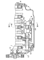
図1はエンジンの要部縦断面図であり、図2は図1のII‐II線について見た断面図である。エンジンEは、4本のシリンダが略鉛直方向に配置され、クランクシャフト1が水平方向に配置された直列4気筒エンジンである。エンジン本体はシリンダヘッド2と、該シリンダヘッド2の下面に結合されたシリンダブロック3と、シリンダブロック3の下面に結合されたロアブロック4と、ロアブロック4の下面に結合されたオイルパン5とを備えている。クランクシャフト1のジャーナル部は、シリンダブロック3とロアブロック4との間に形成された2つ割の軸受にて回転自在に軸支されている。
FIG. 1 is a longitudinal sectional view of an essential part of the engine, and FIG. 2 is a sectional view taken along line II-II in FIG. The engine E is an in-line four-cylinder engine in which four cylinders are arranged in a substantially vertical direction and the crankshaft 1 is arranged in a horizontal direction. The engine body includes a
ロアブロック4の下面には、エンジンEの二次振動を低減するための二次バランサ装置6と、トロコイドポンプからなるオイルポンプ7とが一体的に設けられている。
On the lower surface of the
二次バランサ装置6は、一対のバランサシャフト8、9と、これらバランサシャフト8、9を支持、受容する上側ケーシング10a及び下側ケーシング10bとを備えている。バランサシャフト8、9は、ギヤ11a、11bにより互いにギヤ接続されると共に一方のバランサシャフト8の一端に設けられたスプロケット12、無端チェーン13及びクランクシャフト1の一端に設けられたスプロケット14を介してクランクシャフト1から駆動力が伝達され、各バランサシャフト8、9がクランクシャフト1の2倍の回転数で互いに逆方向に回転するようになっている。
The
各バランサシャフト8、9には、その一端近傍と、他端近傍とに比較的小径の第1ジャーナル部8a、9a及び第2ジャーナル部8b、9bが設けられている。また、各バランサシャフト8、9の他端側には第2ジャーナル部8b、9bにより軸線方向前後に2分割されたバランサウェイト8c、8d、9c、9dが設けられている。
The
ここで、第1ジャーナル部8a、9aの軸受16、17は下側ケーシング10bと一体をなす後記するオイルポンプボディ7aに孔状に形成されている。また、各バランサシャフト8、9の中間部に設けられた第2ジャーナル部8b、9bの軸受18、19は、上側ケーシング10aと下側ケーシング10bとを整合させることにより形成される2つ割のメタル軸受となっている。これにより、各バランサシャフト8、9を上側ケーシング10aと下側ケーシング10bとに受容する際に、各バランサシャフト8、9の一端側を下側ケーシング10bの軸受16、17に挿入すると共に軸受18、19の下側ケーシング10b側半割部分に載置し、上側ケーシング10aを整合させ組み付ければ良いことから、各ジャーナル部8a、9a、8b、9bをその強度の確保できる範囲で細くでき、各ジャーナル部8a、9a、8b、9bと各軸受16〜19との摺動抵抗を小さくすることができると共に、ケーシングの小型化及び軽量化も可能になる。尚、第2ジャーナル部8b、9bは各バランサシャフト8、9の他端部に形成しても良い。
Here, the
図3に示すように、互いに組み付けた上側ケーシング10a及び下側ケーシング10bは第1の締結手段としての通しボルト20、21によりロアブロック4に締結される。このとき、図4に示すように、上側ケーシング10a及び下側ケーシング10bを通しボルト20、21によりロアブロック4に直接共締めすれば、部品点数及び組み付け工数を削減できる。
As shown in FIG. 3, the
図5、その要部を拡大した図7、図7のIIX−IIX線について見た図8及び図7のIX−IX線について見た図9に示すように、上側ケーシング10aのギヤ11a、11bを覆う部分はスラスト軸受22、23をなしており、バランサシャフト8と一体をなすギヤ11aの軸線方向両端面に当接している。この上側ケーシング10aのギヤ11a、11bを覆う部分は外方、特に上方に膨出し、この膨出部分の前後面に上側ケーシング10aの上面(外面)と連通するオイル通路24、25が設けられている。このオイル通路24、25が連通する上側ケーシング10aの外面には前後方向に延在するリブ10cがその周囲を覆うように形成されており、エンジンEから飛来または滴下してリブ10c間、即ち油溜まりに入ってきたオイルをオイル通路24、25に導き、好適にギヤ11a、11b及びスラスト軸受22、23に供給するようになっている。また、上記リブ10cにより上側ケーシング10aの剛性が向上しているのは云うまでもなく、特に、図5に示すように、上側ケーシング10aのギヤ11a、11bを覆う膨出部分と、バランサウェイト8c、8d、9c、9dを覆う膨出部分との間にリブ10cが設けられていることにより、その剛性が著しく向上している。
5, FIG. 7 which expanded the principal part, FIG. 8 which looked at the IIX-IIX line of FIG. 7, and FIG. 9 which looked at the IX-IX line of FIG. 7,
一方、図7に良く示すように、後記するオイルポンプボディ7aの上面にも上記同様なリブ7fが形成されている。従って、リブ7f間、即ち油溜まりに入ってきたオイルをも上側ケーシング10aの上面及びオイル通路24を介してスラスト軸受22、23に供給するようになっている。ここで、オイルポンプボディ7aの上面、即ち油溜まりの底面は、これと隣接する上側ケーシング10aの上面、即ち油溜まりの底面よりもHだけ高くなっている。そのため多少の組付誤差があっても充分にスラスト軸受22、23にオイルを供給することが可能となっている。
On the other hand, as shown well in FIG. 7, a
また、図5、図6及び図10に良く示すように、下側ケーシング10bにはオイルポンプ7のオイルポンプボディ7aが一体成形されている。このオイルポンプボディ7aのポンプ室7bに他方のバランサシャフト9の一端部が突入し、トロコイドポンプのインナロータ7cが取り付けられている。このインナロータ7cとアウタロータ7dとを組み合わせてポンプキャップ7eを整合させ、組み付けることによりポンプ室7b及びオイル通路の一部が画定されることとなる。そして、このポンプキャップ7eを図示されない第2の締結手段としてのボルトでロアブロック4に締結する。これで、上記第1の締結手段としての通しボルト20、21と共に二次バランサ装置6及びオイルポンプ7がロアブロック4に固定されることとなる。これにより、二次バランサ装置6のケーシングでのみ締結する場合に比較して締結部位同士を離反させることができ、ロアブロック4(シリンダブロック)への取り付け面の加工精度の誤差が、両バランサシャフト8、9に影響を及ぼさない程度に吸収し得るようになっている。
As well shown in FIGS. 5, 6, and 10, an
この状態で、実際にインナロータ7cがアウタロータ7dと協動して下側ケーシング10bの下部に設けられたオイルストレーナ27からオイル導入通路28を介してオイルパン5内のオイルを吸い上げ、エンジン各部へ供給するようになる。
In this state, the
ここで、図6、図8〜図10に良く示すように、オイルストレーナ27からポンプ室7bに至るオイル導入通路28が、下側ケーシング10bと一体的にその下端に形成され、これにより下側ケーシング10bが補強されている。また、オイル導入通路28はバランサシャフト8とバランサシャフト9との間にその軸線方向と略平行に延在しており、両バランサシャフト8、9間に入り込むことにより、下方に膨出せず、小型化されている。
Here, as well shown in FIGS. 6 and 8 to 10, an
尚、上記したバランサシャフト8とバランサシャフト9との間、即ち両バランサシャフト8、9間とは、両バランサシャフト8、9の最も大径な部分、即ち、バランサウェイト8c、8d、9c、9dの回転軌跡に対する共通の接線Lhよりも、上方側、即ちバランサシャフト8、9の軸心側にオイル導入通路28の一部が配置されていることを意味する。ギヤ11a、11b間も同様である。
The
また、図8に示すように、オイル導入通路28は、下側ケーシング10bの底壁を両バランサシャフト8、9間側及びオイルパン5の底面側に膨出させて画定されている。そのため、下方への膨出が抑えられているばかりでなく、下側の膨出部分がオイルパン5の油面Loに触れることにより、油面Loのあばれを防止することができる。
As shown in FIG. 8, the
一方、図11に良く示すように、バランサウェイト8c、8d、9c、9dの位置する部分では、上側ケーシング10aと下側ケーシング10bとの間に上向きの開口30、31が設けられている。従って、両バランサシャフト8、9の回転に伴いバランサウェイト8c、8d、9c、9dが下側ケーシング10bの底部に溜まったオイルを開口30、31から外部に掻き出すようになっている。また、この開口30、31の上部は補強リブを兼ねる突条32、33に間隙をもって覆われており、エンジンE本体側からの不必要なオイルの進入を防止している。
On the other hand, as shown well in FIG. 11,
以上の説明により明らかなように、本発明によるエンジンのバランサシャフト支持構造によれば、シリンダブロックの下方に一対のバランサシャフトを受容してなるケーシングが上下に割れる上側ケーシング及び下側ケーシングからなり、これら上側または下側ケーシングのいずれかにオイルポンプボディが一体成形され、このオイルポンプボディに両バランサシャフトの一端を挿入すると共に支持し、両ケーシング間に設けられた2つ割の軸受に両バランサシャフトの中間部または他端部を支持する構造とすることで、オイルポンプボディをケーシングと一体成形でき、部品点数及び組み付け工数を削減できると共に一方の軸受が2つ割なので他の部分に比較して、強度を確保できる範囲でジャーナル部を細くすることができ、摺動抵抗を小さくすることができると共に、ケーシングの小型化及び軽量化も可能になる。しかもバランサシャフトの設計自由度も向上する。また、下側ケーシングにオイルポンプボディを一体成形し、上側ケーシング及び下側ケーシングを第1の締結手段でシリンダブロックに締結すると共にオイルポンプボディに於ける上側ケーシングと相反する側より取り付けられたオイルポンプキャップを第2の締結手段でシリンダブロックに締結することで、第1及び第2の締結手段間の距離を極力長くすることが可能となり、上側ケーシング及びオイルポンプキャップのシリンダブロックへの各取付面の加工誤差を吸収し易くなる。 As is apparent from the above description, the engine balancer shaft support structure according to the present invention comprises an upper casing and a lower casing in which a casing formed by receiving a pair of balancer shafts below the cylinder block is vertically split. An oil pump body is integrally formed in either the upper or lower casing, and one end of both balancer shafts is inserted into and supported by the oil pump body, and both balancers are mounted on a split bearing provided between the two casings. By adopting a structure that supports the middle or other end of the shaft, the oil pump body can be integrally formed with the casing, reducing the number of parts and assembly man-hours. The journal part can be made thin as long as the strength can be secured, and the sliding resistance can be reduced. It is possible to fence, becomes possible size and weight of the casing. Moreover, the design freedom of the balancer shaft is improved. Also, the oil pump body is integrally formed in the lower casing, the upper casing and the lower casing are fastened to the cylinder block by the first fastening means, and the oil attached from the side opposite to the upper casing in the oil pump body By fastening the pump cap to the cylinder block with the second fastening means, the distance between the first and second fastening means can be made as long as possible, and each attachment of the upper casing and the oil pump cap to the cylinder block It becomes easy to absorb surface processing errors.
1 クランクシャフト
2 シリンダヘッド
3 シリンダブロック
4 ロアブロック
5 オイルパン
6 二次バランサ装置
7 オイルポンプ
7a オイルポンプボディ
7b ポンプ室
7c インナロータ
7d アウタロータ
7e ポンプキャップ
7f リブ
8、9 バランサシャフト
8a、9a 第1ジャーナル部
8b、9b 第2ジャーナル部
8c、8d、9c、9d バランサウェイト
10a 上側ケーシング
10b 下側ケーシング
10c リブ
11a、11b ギヤ
12 スプロケット
13 無端チェーン
14 スプロケット
16、17 軸受
18、19 軸受
20、21 通しボルト
22、23 スラスト軸受
24、25 オイル通路
27 オイルストレーナ
28 オイル導入通路
30、31 開口
32、33 突条
E エンジン
DESCRIPTION OF SYMBOLS 1
Claims (5)
前記ケーシングが上下に割れる上側ケーシング及び下側ケーシングからなり、
前記上側ケーシングにおける前記バランサシャフトの直上部分には、該上側ケーシングの上面と連通して前記バランサシャフトへオイルを供給するオイル通路が設けられ、
前記上側ケーシングの外面には、バランサシャフト軸方向に延在するリブが前記オイル通路の周囲を覆うように形成されることを特徴とするエンジンのバランサシャフト支持構造。 In an engine in which a casing configured to receive a pair of balancer shafts is disposed below a cylinder block,
The casing is composed of an upper casing and a lower casing that are vertically split,
An oil passage for supplying oil to the balancer shaft in communication with the upper surface of the upper casing is provided in a portion directly above the balancer shaft in the upper casing ,
A balancer shaft support structure for an engine, wherein a rib extending in an axial direction of the balancer shaft is formed on an outer surface of the upper casing so as to cover the periphery of the oil passage .
前記オイルポンプのオイルポンプボディに前記バランサシャフトの一端が挿入されると共に支持され、One end of the balancer shaft is inserted into and supported by the oil pump body of the oil pump,
前記オイルポンプを駆動するバランサシャフトの上方に前記リブ及び前記オイル通路が設けられることを特徴とする、請求項1に記載のエンジンのバランサシャフト支持構造。The balancer shaft support structure for an engine according to claim 1, wherein the rib and the oil passage are provided above a balancer shaft for driving the oil pump.
前記上側ケーシングにおける前記ギヤを覆う部分及びバランサウェイトを覆う部分は、それぞれ上方に膨出して形成され、The portion that covers the gear and the portion that covers the balancer weight in the upper casing are each formed to bulge upward,
前記リブは前記膨出部同士をつなぐようにして設けられることを特徴とする、請求項1または請求項2に記載のエンジンのバランサシャフト支持構造。The balancer shaft support structure for an engine according to claim 1 or 2, wherein the rib is provided so as to connect the bulging portions.
前記オイル導入通路は、前記バランサシャフトの軸線方向と略平行に延在することを特徴とする請求項2または請求項3に記載のエンジンのバランサシャフト支持構造。The balancer shaft support structure for an engine according to claim 2 or 3, wherein the oil introduction passage extends substantially parallel to an axial direction of the balancer shaft.
Priority Applications (1)
| Application Number | Priority Date | Filing Date | Title |
|---|---|---|---|
| JP2007322952A JP4594373B2 (en) | 2007-12-14 | 2007-12-14 | Engine balancer shaft support structure |
Applications Claiming Priority (1)
| Application Number | Priority Date | Filing Date | Title |
|---|---|---|---|
| JP2007322952A JP4594373B2 (en) | 2007-12-14 | 2007-12-14 | Engine balancer shaft support structure |
Related Parent Applications (1)
| Application Number | Title | Priority Date | Filing Date |
|---|---|---|---|
| JP22815098A Division JP4072251B2 (en) | 1998-08-12 | 1998-08-12 | Engine balancer shaft support structure |
Publications (3)
| Publication Number | Publication Date |
|---|---|
| JP2008144971A JP2008144971A (en) | 2008-06-26 |
| JP2008144971A5 JP2008144971A5 (en) | 2009-10-08 |
| JP4594373B2 true JP4594373B2 (en) | 2010-12-08 |
Family
ID=39605356
Family Applications (1)
| Application Number | Title | Priority Date | Filing Date |
|---|---|---|---|
| JP2007322952A Expired - Fee Related JP4594373B2 (en) | 2007-12-14 | 2007-12-14 | Engine balancer shaft support structure |
Country Status (1)
| Country | Link |
|---|---|
| JP (1) | JP4594373B2 (en) |
Families Citing this family (2)
| Publication number | Priority date | Publication date | Assignee | Title |
|---|---|---|---|---|
| JP5226728B2 (en) * | 2010-04-07 | 2013-07-03 | 日立オートモティブシステムズ株式会社 | Balancer device for internal combustion engine |
| JP2020076412A (en) * | 2017-03-16 | 2020-05-21 | 日立オートモティブシステムズ株式会社 | Balancer device of internal combustion engine |
Family Cites Families (3)
| Publication number | Priority date | Publication date | Assignee | Title |
|---|---|---|---|---|
| JP3087531B2 (en) * | 1993-09-17 | 2000-09-11 | 日産自動車株式会社 | Balancer device for internal combustion engine |
| JP3496247B2 (en) * | 1993-09-22 | 2004-02-09 | 日産自動車株式会社 | Balancer device for internal combustion engine |
| JP3488774B2 (en) * | 1996-02-06 | 2004-01-19 | 本田技研工業株式会社 | Support structure of balancer shaft in engine |
-
2007
- 2007-12-14 JP JP2007322952A patent/JP4594373B2/en not_active Expired - Fee Related
Also Published As
| Publication number | Publication date |
|---|---|
| JP2008144971A (en) | 2008-06-26 |
Similar Documents
| Publication | Publication Date | Title |
|---|---|---|
| JP4072251B2 (en) | Engine balancer shaft support structure | |
| EP2278131B1 (en) | Balance shaft, housing for balance shaft and engine oil return passage | |
| JP3554429B2 (en) | Rotary shaft lubrication structure | |
| EP1081345A1 (en) | Balance shaft housing | |
| JP3643505B2 (en) | Housing for balance shaft | |
| JP4594373B2 (en) | Engine balancer shaft support structure | |
| JP5357132B2 (en) | Crankcase integrated balancer device | |
| JP3685693B2 (en) | Balance axis | |
| JP3712864B2 (en) | Engine balancer shaft support structure | |
| EP1517019B1 (en) | Balancer device of an engine, engine provided therewith and method of assembling a balancer device to an engine | |
| US7565891B2 (en) | Engine for vehicle | |
| JP3585376B2 (en) | Engine balancer shaft support structure | |
| JP3873958B2 (en) | Engine balancer equipment | |
| JP3739689B2 (en) | Engine balance device housing | |
| JP3730610B2 (en) | Engine oil return passage | |
| JP3739687B2 (en) | Balancer shaft housing | |
| JP3730557B2 (en) | Balancer shaft for engine balancing device | |
| KR100928770B1 (en) | Receiving structure of counter balance shaft | |
| JP4204571B2 (en) | Engine balance device housing | |
| JP4374882B2 (en) | Engine lubrication structure with balancer device | |
| JP4309875B2 (en) | Engine balancing device | |
| JP3808749B2 (en) | Engine balancing device | |
| JP3873957B2 (en) | Engine balancer equipment | |
| JP4658265B2 (en) | Engine balancing device | |
| JP2003113898A (en) | Housing for engine balancing device |
Legal Events
| Date | Code | Title | Description |
|---|---|---|---|
| A521 | Written amendment |
Free format text: JAPANESE INTERMEDIATE CODE: A523 Effective date: 20090820 |
|
| A977 | Report on retrieval |
Free format text: JAPANESE INTERMEDIATE CODE: A971007 Effective date: 20100531 |
|
| A131 | Notification of reasons for refusal |
Free format text: JAPANESE INTERMEDIATE CODE: A131 Effective date: 20100608 |
|
| RD13 | Notification of appointment of power of sub attorney |
Free format text: JAPANESE INTERMEDIATE CODE: A7433 Effective date: 20100706 |
|
| A521 | Written amendment |
Free format text: JAPANESE INTERMEDIATE CODE: A821 Effective date: 20100706 |
|
| TRDD | Decision of grant or rejection written | ||
| A01 | Written decision to grant a patent or to grant a registration (utility model) |
Free format text: JAPANESE INTERMEDIATE CODE: A01 Effective date: 20100831 |
|
| A01 | Written decision to grant a patent or to grant a registration (utility model) |
Free format text: JAPANESE INTERMEDIATE CODE: A01 |
|
| A61 | First payment of annual fees (during grant procedure) |
Free format text: JAPANESE INTERMEDIATE CODE: A61 Effective date: 20100916 |
|
| FPAY | Renewal fee payment (event date is renewal date of database) |
Free format text: PAYMENT UNTIL: 20130924 Year of fee payment: 3 |
|
| R150 | Certificate of patent or registration of utility model |
Free format text: JAPANESE INTERMEDIATE CODE: R150 |
|
| LAPS | Cancellation because of no payment of annual fees |