JP3585376B2 - Engine balancer shaft support structure - Google Patents
Engine balancer shaft support structure Download PDFInfo
- Publication number
- JP3585376B2 JP3585376B2 JP22815398A JP22815398A JP3585376B2 JP 3585376 B2 JP3585376 B2 JP 3585376B2 JP 22815398 A JP22815398 A JP 22815398A JP 22815398 A JP22815398 A JP 22815398A JP 3585376 B2 JP3585376 B2 JP 3585376B2
- Authority
- JP
- Japan
- Prior art keywords
- casing
- oil
- balancer
- balancer shaft
- engine
- Prior art date
- Legal status (The legal status is an assumption and is not a legal conclusion. Google has not performed a legal analysis and makes no representation as to the accuracy of the status listed.)
- Expired - Fee Related
Links
Images


Description
【0001】
【発明の属する技術分野】
本発明はシリンダブロックの下方にバランサシャフトを配置してなるエンジンに関し、特にそのバランサシャフトの支持構造に関するものである。
【0002】
【従来の技術】
従来から、シリンダブロックの下方に二次バランサ装置を配置してなるエンジンがある(例えば、持開昭63‐106443号公報等参照)。このようなエンジンに於いて、上記バランサ装置はシリンブロック下方のオイルパン内に設けられたケーシングに支持された一対のバランサシャフトからなり、各バランサシャフトは互いにギヤ接続されると共に一方のバランサシャフトにチェーン等を介してクランクシャフトから駆動力が伝達され、各バランサシャフトがクランクシャフトの2倍の回転数で互いに逆方向に回転するようになっている。
【0003】
上記構造のバランサ装置のスラスト軸受はあまり大きな力を受けないことから、できる限り構造を単純化することが望ましい。従来は、例えば各バランサシャフトのバランサウェイトの端面をケーシングの内面に当接させていた。
【0004】
【発明が解決しようとする課題】
しかしながら、バランサシャフトは単独では不安定なことからその端面の研磨の精度を高めることが困難であるという問題があり、また当接面を確保するために、バランサシャフト全体が重量化するという問題もある。
【0005】
そこで、各バランサシャフト同士を接続するべく該バランサシャフトの外周に圧入等により一体的に固定されたギヤの端面をケーシングの内面に当接させ、スラスト軸受とすると良いが、その潤滑性を確保するべくオイルを供給する必要があり、専用のオイル通路を設けると構造が複雑になり、場合によってはバランサ装置の大型化、重量化を伴う。
【0006】
本発明は上述の如き従来技術の問題点に鑑みなされたものであり、バランサ装置のスラスト軸受へのオイルの供給構造を単純化し、バランサ装置、延いてはエンジンを小型化、軽量化することが可能なエンジンのバランサシャフト支持構造を提供することを目的とする。
【0007】
【課題を解決するための手段】
上述の目的は、本発明によれば、シリンダブロック下方のオイルパン内に一対のバランサシャフトを互いに平行に受容してなるケーシングが配置され、前記各バランサシャフトに、該バランサシャフト同士を互いに接続するギヤが設けられ、前記ギヤの両端面が、前記ケーシングに当接することによりスラスト軸受部をなすエンジンのバランサシャフト支持構造であって、前記ケーシングの上面に前記バランサシャフトの軸線方向に延在する複数のリブが形成され、前記ケーシングの前記ギヤを覆う部分が他の部分に比較して上方に膨出しており、前記シリンダブロック側から滴下してリブ間に溜まったオイルを前記スラスト軸受に導くべく、前記ケーシングの前記ギヤを覆う膨出部分に、その下面の上下位置が前記ケーシング上面の他の部分と略一致するオイル通路が形成されていることを特徴とするエンジンのバランサシャフト支持構造を提供することにより達成される。
【0008】
このようにすることで、別途専用にオイル通路を設けなくても、上方から滴下するオイルが好適にスラスト軸受に導かれるようになる。また、そのためのリブによりケーシングの剛性が向上する。
【0009】
また、前記ケーシングに於ける前記バランサシャフトの軸線方向端部にオイルポンプが一体的に設けられている場合、前記オイルポンプボディの上面にも前記バランサシャフトの軸線方向に延在する複数のリブを形成し、前記リブが形成されたオイルポンプボディ上面を前記ケーシング上面に隣接させ、前記オイルポンプボディ上面に溜まったオイルをも前記ケーシング上面及び前記オイル通路を介して前記スラスト軸受に導くようにすることで、油溜まり領域を拡大され、一層好適にオイルがスラスト軸受に導かれるようになる。
【0010】
【発明の実施の形態】
以下、本発明の好適な実施の形態を、添付図面を参照して詳細に説明する。
【0011】
図1はエンジンの要部縦断面図であり、図2は図1のII‐II線について見た断面図である。エンジンEは、4本のシリンダが略鉛直方向に配置され、クランクシャフト1が水平方向に配置された直列4気筒エンジンである。エンジン本体はシリンダヘッド2と、該シリンダヘッド2の下面に結合されたシリンダブロック3と、シリンダブロック3の下面に結合されたロアブロック4と、ロアブロック4の下面に結合されたオイルパン5とを備えている。クランクシャフト1のジャーナル部は、シリンダブロック3とロアブロック4との間に形成された2つ割の軸受にて回転自在に軸支されている。
【0012】
ロアブロック4の下面には、エンジンEの二次振動を低減するための二次バランサ装置6と、トロコイドポンプからなるオイルポンプ7とが一体的に設けられている。
【0013】
二次バランサ装置6は、一対のバランサシャフト8、9と、これらバランサシャフト8、9を支持、受容する上側ケーシング10a及び下側ケーシング10bとを備えている。バランサシャフト8、9は、ギヤ11a、11bにより互いにギヤ接続されると共に一方のバランサシャフト8の一端に設けられたスプロケット12、無端チェーン13及びクランクシャフト1の一端に設けられたスプロケット14を介してクランクシャフト1から駆動力が伝達され、各バランサシャフト8、9がクランクシャフト1の2倍の回転数で互いに逆方向に回転するようになっている。
【0014】
各バランサシャフト8、9には、その一端近傍と、他端近傍とに比較的小径の第1ジャーナル部8a、9a及び第2ジャーナル部8b、9bが設けられている。また、各バランサシャフト8、9の他端側には第2ジャーナル部8b、9bにより軸線方向前後に2分割されたバランサウェイト8c、8d、9c、9dが設けられている。
【0015】
ここで、第1ジャーナル部8a、9aの軸受16、17は下側ケーシング10bと一体をなす後記するオイルポンプボディ7aに孔状に形成されている。また、各バランサシャフト8、9の中間部に設けられた第2ジャーナル部8b、9bの軸受18、19は、上側ケーシング10aと下側ケーシング10bとを整合させることにより形成される2つ割のメタル軸受となっている。これにより、各バランサシャフト8、9を上側ケーシング10aと下側ケーシング10bとに受容する際に、各バランサシャフト8、9の一端側を下側ケーシング10bの軸受16、17に挿入すると共に軸受18、19の下側ケーシング10b側半割部分に載置し、上側ケーシング10aを整合させ組み付ければ良いことから、各ジャーナル部8a、9a、8b、9bをその強度の確保できる範囲で細くでき、各ジャーナル部8a、9a、8b、9bと各軸受16〜19との摺動抵抗を小さくすることができると共に、ケーシングの小型化及び軽量化も可能になる。尚、第2ジャーナル部8b、9bは各バランサシャフト8、9の他端部に形成しても良い。
【0016】
図3に示すように、互いに組み付けた上側ケーシング10a及び下側ケーシング10bは通しボルト20、21によりロアブロック4に締結される。このとき、図4に示すように、上側ケーシング10a及び下側ケーシング10bを通しボルト20、21によりロアブロック4に直接共締めすれば、部品点数及び組み付け工数を削減できる。
【0017】
図5、その要部を拡大した図7、図7のIIX−IIX線について見た図8及び図7のIX−IX線について見た図9に示すように、上側ケーシング10aのギヤ11a、11bを覆う部分はスラスト軸受22、23をなしており、バランサシャフト8と一体をなすギヤ11aの軸線方向両端面に当接している。この上側ケーシング10aのギヤ11a、11bを覆う部分は外方、特に上方に膨出し、この膨出部分の前後面に上側ケーシング10aの上面(外面)と連通するオイル通路24、25が設けられている。このオイル通路24、25が連通する上側ケーシング10aの外面にはバランサシャフト8、9の軸線方向、即ち前後方向に延在するリブ10cがその周囲を覆うように形成されており、エンジンEから飛来または滴下してリブ10c間、即ち油溜まりに入ってきたオイルをオイル通路24、25に導き、好適にギヤ11a、11b及びスラスト軸受22、23に供給するようになっている。また、上記リブ10cにより上側ケーシング10aの剛性が向上しているのは云うまでもなく、特に、図5に示すように、上側ケーシング10aのギヤ11a、11bを覆う膨出部分と、バランサウェイト8c、8d、9c、9dを覆う膨出部分との間にリブ10cが設けられていることにより、その剛性が著しく向上している。
【0018】
一方、図7に良く示すように、後記するオイルポンプボディ7aの上面にも上記同様にバランサシャフト8、9の軸線方向、即ち前後方向に延在するリブ7fが形成されている。従って、リブ7f間、即ち油溜まりに入ってきたオイルをも上側ケーシング10aの上面及びオイル通路24を介してスラスト軸受22、23に供給するようになっている。ここで、オイルポンプボディ7aの上面、即ち油溜まりの底面は、上側ケーシング10aの上面、即ち油溜まりの底面と隣接し、オイルポンプボディ7aの上面の方がこれと隣接する上側ケーシング10aの上面よりもHだけ高くなっている。そのため多少の組付誤差があっても充分にスラスト軸受22、23にオイルを供給することが可能となっている。また、この場合の隣接とはオイルが受け渡される範囲に近接していることを意味し、実際には図7に示すように組み付け誤差などを考慮して多少の隙間があっても良い。
【0019】
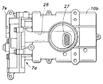
図5、図6及び図10に良く示すように、下側ケーシング10bにはオイルポンプ7のオイルポンプボディ7aが一体成形されている。このオイルポンプボディ7aのポンプ室7bに他方のバランサシャフト9の一端部が突入し、トロコイドポンプのインナロータ7cが取り付けられている。このインナロータ7cとアウタロータ7dとを組み合わせてポンプキャップ7eを整合させ、組み付けることによりポンプ室7b及びオイル通路の一部が画定されることとなる。そして、実際にインナロータ7cがアウタロータ7dと協動して下側ケーシング10bの下部に設けられたオイルストレーナ27からオイル導入通路28を介してオイルパン5内のオイルを吸い上げ、エンジン各部へ供給するようになっている。
【0020】
ここで、図6、図8〜図10に良く示すように、オイルストレーナ27からポンプ室7bに至るオイル導入通路28が、下側ケーシング10bと一体的にその下端に形成され、これにより下側ケーシング10bが補強されている。また、オイル導入通路28はバランサシャフト8とバランサシャフト9との間にその軸線方向と略平行に延在しており、両バランサシャフト8、9間に入り込むことにより、下方に膨出せず、小型化されている。
【0021】
尚、上記したバランサシャフト8とバランサシャフト9との間、即ち両バランサシャフト8、9間とは、両バランサシャフト8、9の最も大径な部分、即ち、バランサウェイト8c、8d、9c、9dの回転軌跡に対する共通の接線Lhよりも、上方側、即ちバランサシャフト8、9の軸心側にオイル導入通路28の一部が配置されていることを意味する。ギヤ11a、11b間も同様である。
【0022】
また、図8に示すように、オイル導入通路28は、下側ケーシング10bの底壁を両バランサシャフト8、9間側及びオイルパン5の底面側に膨出させて画定されている。そのため、下方への膨出が抑えられているばかりでなく、下側の膨出部分がオイルパン5の油面Loに触れることにより、油面Loのあばれを防止することができる。
【0023】
一方、図11に良く示すように、バランサウェイト8c、8d、9c、9dの位置する部分では、上側ケーシング10aと下側ケーシング10bとの間に上向きの開口30、31が設けられている。従って、両バランサシャフト8、9の回転に伴いバランサウェイト8c、8d、9c、9dが下側ケーシング10bの底部に溜まったオイルを開口30、31から外部に掻き出すようになっている。また、この開口30、31の上部は補強リブを兼ねる突条32、33に間隙をもって覆われており、エンジンE本体側からの不必要なオイルの進入を防止している。
【0024】
【発明の効果】
以上の説明により明らかなように、本発明によるエンジンのバランサシャフト支持構造によれば、一対のバランサシャフト同士を接続するギヤの両端面が、これらを互いに平行に受容するケーシングの内面に当接することによりスラスト軸受部をなし、ケーシングの上記ギヤを覆う部分が他の部分に比較して上方に膨出し、ケーシングの上面にバランサシャフトの軸線方向に延在する複数のリブが形成されたバランサ装置の上記リブ間に溜まったオイルをスラスト軸受に導くためのオイル通路を、ケーシングの上記膨出部分に形成する構造とすることで、別途専用にオイル通路を設けなくても、上方から滴下するオイルが好適にスラスト軸受に導かれるため、その構造が単純になり、装置全体が、小型化、軽量化される。また、上記リブによりケーシングの剛性が向上する。また、ケーシングに於けるバランサシャフトの軸線方向端部にオイルポンプが一体的に設けられている場合、このオイルポンプボディの上面にも軸線方向に延在する複数のリブを形成し、リブが形成されたオイルポンプボディ上面をこれと隣接するケーシング上面よりも高くし、オイルポンプボディ上面に溜まったオイルをもケーシング上面及びオイル通路が介してスラスト軸受に導くようにすることで、油溜まり領域が拡大され、一層好適にオイルがスラスト軸受に導かれるようになり、スラスト軸受の潤滑性がより充分に確保できるようになる。
【図面の簡単な説明】
【図1】エンジンの要部縦断面図。
【図2】図1のII‐II線について見た断面図。
【図3】図2のIII−III線について見た断面図。
【図4】本実施形態の変形例を示す図3と同様な図。
【図5】図1のV−V線について見た断面図。
【図6】本発明が適用された二次バランサ装置の底面図。
【図7】図5の要部拡大図。
【図8】図5のIIX−IIX線について見た断面図。
【図9】図5のIX−IX線について見た断面図。
【図10】図2のX−X線について見た断面図。
【図11】図2のXI−XI線について見た断面図。
【符号の説明】
1 クランクシャフト
2 シリンダヘッド
3 シリンダブロック
4 ロアブロック
5 オイルパン
6 二次バランサ装置
7 オイルポンプ
7a オイルポンプボディ
7b ポンプ室
7c インナロータ
7d アウタロータ
7e ポンプキャップ
7f リブ
8、9 バランサシャフト
8a、9a 第1ジャーナル部
8b、9b 第2ジャーナル部
8c、8d、9c、9d バランサウェイト
10a 上側ケーシング
10b 下側ケーシング
10c リブ
11a、11b ギヤ
12 スプロケット
13 無端チェーン
14 スプロケット
16、17 軸受
18、19 軸受
20、21 通しボルト
22、23 スラスト軸受
24、25 オイル通路
27 オイルストレーナ
28 オイル導入通路
30、31 開口
32、33 突条
E エンジン[0001]
TECHNICAL FIELD OF THE INVENTION
The present invention relates to an engine having a balancer shaft disposed below a cylinder block, and more particularly to a support structure for the balancer shaft.
[0002]
[Prior art]
2. Description of the Related Art Conventionally, there is an engine in which a secondary balancer device is disposed below a cylinder block (for example, see Japanese Unexamined Patent Publication No. 63-106443). In such an engine, the balancer device includes a pair of balancer shafts supported by a casing provided in an oil pan below the syringe block. Each balancer shaft is gear-connected to each other and connected to one of the balancer shafts. Driving force is transmitted from the crankshaft via a chain or the like, and each balancer shaft rotates in opposite directions at twice the number of rotations of the crankshaft.
[0003]
Since the thrust bearing of the balancer device having the above structure does not receive much force, it is desirable to simplify the structure as much as possible. Conventionally, for example, the end face of the balancer weight of each balancer shaft is brought into contact with the inner face of the casing.
[0004]
[Problems to be solved by the invention]
However, since the balancer shaft alone is unstable, there is a problem that it is difficult to improve the accuracy of the polishing of the end face, and there is also a problem that the entire balancer shaft becomes heavy in order to secure a contact surface. is there.
[0005]
Therefore, in order to connect the balancer shafts to each other, the end face of the gear integrally fixed to the outer periphery of the balancer shaft by press fitting or the like is brought into contact with the inner surface of the casing to form a thrust bearing. It is necessary to supply oil so that providing a dedicated oil passage complicates the structure, and in some cases, increases the size and weight of the balancer device.
[0006]
SUMMARY OF THE INVENTION The present invention has been made in view of the above-mentioned problems of the related art, and simplifies a structure for supplying oil to a thrust bearing of a balancer device, and makes it possible to reduce the size and weight of a balancer device and, consequently, an engine. It is an object to provide a possible engine balancer shaft support structure.
[0007]
[Means for Solving the Problems]
According to the present invention, according to the present invention, a casing configured to receive a pair of balancer shafts in parallel with each other is arranged in an oil pan below a cylinder block, and the balancer shafts are connected to each of the balancer shafts. A gear is provided, and a balancer shaft support structure of an engine in which both end surfaces of the gear abut on the casing to form a thrust bearing portion, wherein a plurality of shafts extend on an upper surface of the casing in an axial direction of the balancer shaft. The portion of the casing that covers the gear is bulged upward as compared with the other portions, and the oil dripped from the cylinder block side and accumulated between the ribs is guided to the thrust bearing. In the bulging portion of the casing that covers the gear, the upper and lower positions of the lower surface are the other portions of the upper surface of the casing. It is achieved by to provide a balancer shaft supporting structure in an engine, characterized in that substantially coincide oil passage which is formed with.
[0008]
By doing so, the oil dripping from above can be suitably guided to the thrust bearing without separately providing an oil passage. Further, the rigidity of the casing is improved by the ribs for that purpose.
[0009]
When an oil pump is integrally provided at an axial end of the balancer shaft in the casing, a plurality of ribs extending in the axial direction of the balancer shaft are also provided on the upper surface of the oil pump body. The upper surface of the oil pump body having the ribs formed thereon is adjacent to the upper surface of the casing, and oil accumulated on the upper surface of the oil pump body is also guided to the thrust bearing via the upper surface of the casing and the oil passage. As a result, the oil accumulation region is enlarged, and the oil is more suitably guided to the thrust bearing.
[0010]
BEST MODE FOR CARRYING OUT THE INVENTION
Hereinafter, preferred embodiments of the present invention will be described in detail with reference to the accompanying drawings.
[0011]
FIG. 1 is a longitudinal sectional view of a main part of the engine, and FIG. 2 is a sectional view taken along line II-II in FIG. The engine E is an in-line four-cylinder engine in which four cylinders are arranged in a substantially vertical direction and the crankshaft 1 is arranged in a horizontal direction. The engine body includes a
[0012]
On the lower surface of the
[0013]
The secondary balancer device 6 includes a pair of
[0014]
Each of the
[0015]
Here, the
[0016]
As shown in FIG. 3, the
[0017]
As shown in FIG. 5, FIG. 7 in which main parts are enlarged, FIG. 8 as viewed along line IIX-IIX in FIG. 7, and FIG. 9 as viewed along line IX-IX in FIG. 7, the
[0018]
On the other hand, as shown well in FIG. 7,
[0019]
As shown in FIGS. 5, 6, and 10, an
[0020]
Here, as best shown in FIGS. 6 and 8 to 10, an
[0021]
The portion between the
[0022]
As shown in FIG. 8, the
[0023]
On the other hand, as well shown in FIG. 11,
[0024]
【The invention's effect】
As is apparent from the above description, according to the engine balancer shaft support structure of the present invention, both end surfaces of the gear connecting the pair of balancer shafts come into contact with the inner surface of the casing that receives the gears in parallel with each other. A part covering the gear of the casing bulges upward compared to other parts, and a plurality of ribs extending in the axial direction of the balancer shaft are formed on the upper surface of the casing. By forming an oil passage for guiding the oil accumulated between the ribs to the thrust bearing at the bulging portion of the casing, oil dripping from above can be provided without providing a dedicated oil passage separately. Since the guide is preferably guided to the thrust bearing, the structure is simplified, and the entire apparatus is reduced in size and weight. Further, the rigidity of the casing is improved by the ribs. When an oil pump is integrally provided at the axial end of the balancer shaft in the casing, a plurality of ribs extending in the axial direction are formed on the upper surface of the oil pump body, and the ribs are formed. The upper surface of the oil pump body is made higher than the upper surface of the casing adjacent to the oil pump body, and the oil accumulated on the upper surface of the oil pump body is guided to the thrust bearing via the upper surface of the casing and the oil passage. As a result, the oil is more preferably guided to the thrust bearing, and the lubrication of the thrust bearing can be more sufficiently ensured.
[Brief description of the drawings]
FIG. 1 is a longitudinal sectional view of a main part of an engine.
FIG. 2 is a sectional view taken along line II-II in FIG. 1;
FIG. 3 is a sectional view taken along line III-III in FIG. 2;
FIG. 4 is a view similar to FIG. 3, showing a modification of the embodiment.
FIG. 5 is a sectional view taken along line VV in FIG. 1;
FIG. 6 is a bottom view of a secondary balancer device to which the present invention is applied.
FIG. 7 is an enlarged view of a main part of FIG. 5;
FIG. 8 is a sectional view taken along line IIX-IIX in FIG. 5;
FIG. 9 is a sectional view taken along line IX-IX in FIG. 5;
FIG. 10 is a sectional view taken along line XX of FIG. 2;
FIG. 11 is a sectional view taken along line XI-XI in FIG. 2;
[Explanation of symbols]
Reference Signs List 1
Claims (2)
前記ケーシングの上面に前記バランサシャフトの軸線方向に延在する複数のリブが形成され、
前記ケーシングの前記ギヤを覆う部分が他の部分に比較して上方に膨出しており、
前記ケーシングの前記ギヤを覆う膨出部分に、前記シリンダブロック側から滴下してリブ間に溜まったオイルを前記スラスト軸受に導くためのオイル通路が形成されていることを特徴とするエンジンのバランサシャフト支持構造。A casing that receives a pair of balancer shafts in parallel in the oil pan below the cylinder block is arranged, and a gear that connects the balancer shafts to each other is provided on each of the balancer shafts. An engine balancer shaft support structure that forms a thrust bearing by contacting the casing,
A plurality of ribs extending in an axial direction of the balancer shaft are formed on an upper surface of the casing,
A portion of the casing covering the gear bulges upward compared to other portions,
An engine balancer shaft, wherein an oil passage for guiding oil dripped from the cylinder block side and accumulated between ribs to the thrust bearing is formed in a bulging portion of the casing covering the gear. Support structure.
前記オイルポンプボディの上面にも前記バランサシャフトの軸線方向に延在する複数のリブが形成され、
前記リブが形成されたオイルポンプボディ上面が前記ケーシング上面に隣接しており、
前記オイルポンプボディ上面に溜まったオイルをも前記ケーシング上面及び前記オイル通路を介して前記スラスト軸受に導くようになっていることを特徴とする請求項1に記載のエンジンのバランサシャフト支持構造。An oil pump is integrally provided at an axial end of the balancer shaft in the casing,
A plurality of ribs extending in the axial direction of the balancer shaft are also formed on the upper surface of the oil pump body,
The oil pump body upper surface on which the rib is formed is adjacent to the casing upper surface,
2. The engine balancer shaft support structure according to claim 1, wherein oil accumulated on the upper surface of the oil pump body is also guided to the thrust bearing via the upper surface of the casing and the oil passage. 3.
Priority Applications (1)
| Application Number | Priority Date | Filing Date | Title |
|---|---|---|---|
| JP22815398A JP3585376B2 (en) | 1998-08-12 | 1998-08-12 | Engine balancer shaft support structure |
Applications Claiming Priority (1)
| Application Number | Priority Date | Filing Date | Title |
|---|---|---|---|
| JP22815398A JP3585376B2 (en) | 1998-08-12 | 1998-08-12 | Engine balancer shaft support structure |
Publications (2)
| Publication Number | Publication Date |
|---|---|
| JP2000065149A JP2000065149A (en) | 2000-03-03 |
| JP3585376B2 true JP3585376B2 (en) | 2004-11-04 |
Family
ID=16872064
Family Applications (1)
| Application Number | Title | Priority Date | Filing Date |
|---|---|---|---|
| JP22815398A Expired - Fee Related JP3585376B2 (en) | 1998-08-12 | 1998-08-12 | Engine balancer shaft support structure |
Country Status (1)
| Country | Link |
|---|---|
| JP (1) | JP3585376B2 (en) |
Families Citing this family (2)
| Publication number | Priority date | Publication date | Assignee | Title |
|---|---|---|---|---|
| JP4206846B2 (en) * | 2003-07-07 | 2009-01-14 | 三菱自動車工業株式会社 | Balancer shaft and engine |
| JP4658265B2 (en) * | 2007-12-03 | 2011-03-23 | 本田技研工業株式会社 | Engine balancing device |
-
1998
- 1998-08-12 JP JP22815398A patent/JP3585376B2/en not_active Expired - Fee Related
Also Published As
| Publication number | Publication date |
|---|---|
| JP2000065149A (en) | 2000-03-03 |
Similar Documents
| Publication | Publication Date | Title |
|---|---|---|
| JP4072251B2 (en) | Engine balancer shaft support structure | |
| JP3554429B2 (en) | Rotary shaft lubrication structure | |
| EP1081345B1 (en) | Balance shaft housing | |
| EP0789166B1 (en) | Balance shaft supporting structure in engine | |
| JP3643505B2 (en) | Housing for balance shaft | |
| JP5357132B2 (en) | Crankcase integrated balancer device | |
| JP3685693B2 (en) | Balance axis | |
| JP3585376B2 (en) | Engine balancer shaft support structure | |
| JP3488774B2 (en) | Support structure of balancer shaft in engine | |
| JP3712864B2 (en) | Engine balancer shaft support structure | |
| JP4594373B2 (en) | Engine balancer shaft support structure | |
| JP4391914B2 (en) | engine | |
| JP4161202B2 (en) | Mounting structure of balancer housing in engine | |
| JP3739689B2 (en) | Engine balance device housing | |
| JP3668548B2 (en) | Support structure of balancer shaft in engine | |
| JP2556374B2 (en) | Engine cylinder block | |
| JP3802800B2 (en) | Engine oil pump cover positioning structure | |
| JP3762681B2 (en) | Engine balance device housing | |
| JP3127354B2 (en) | Support structure for chain tensioner in engine | |
| JP2003090225A (en) | Housing for balancing shaft | |
| JP2542029B2 (en) | Bearing lubrication system for multi-cylinder rotary piston engine | |
| JP4233680B2 (en) | Engine oil pump equipment | |
| JP2514497Y2 (en) | Bearing structure in cylinder block | |
| JP3985313B2 (en) | Structure of locating plate for internal combustion engine | |
| JPH082409Y2 (en) | Engine cylinder block structure |
Legal Events
| Date | Code | Title | Description |
|---|---|---|---|
| A977 | Report on retrieval |
Free format text: JAPANESE INTERMEDIATE CODE: A971007 Effective date: 20040524 |
|
| TRDD | Decision of grant or rejection written | ||
| A01 | Written decision to grant a patent or to grant a registration (utility model) |
Free format text: JAPANESE INTERMEDIATE CODE: A01 Effective date: 20040727 |
|
| A61 | First payment of annual fees (during grant procedure) |
Free format text: JAPANESE INTERMEDIATE CODE: A61 Effective date: 20040803 |
|
| R150 | Certificate of patent or registration of utility model |
Free format text: JAPANESE INTERMEDIATE CODE: R150 |
|
| FPAY | Renewal fee payment (event date is renewal date of database) |
Free format text: PAYMENT UNTIL: 20080813 Year of fee payment: 4 |
|
| FPAY | Renewal fee payment (event date is renewal date of database) |
Free format text: PAYMENT UNTIL: 20090813 Year of fee payment: 5 |
|
| FPAY | Renewal fee payment (event date is renewal date of database) |
Free format text: PAYMENT UNTIL: 20100813 Year of fee payment: 6 |
|
| FPAY | Renewal fee payment (event date is renewal date of database) |
Free format text: PAYMENT UNTIL: 20100813 Year of fee payment: 6 |
|
| FPAY | Renewal fee payment (event date is renewal date of database) |
Free format text: PAYMENT UNTIL: 20110813 Year of fee payment: 7 |
|
| FPAY | Renewal fee payment (event date is renewal date of database) |
Free format text: PAYMENT UNTIL: 20110813 Year of fee payment: 7 |
|
| FPAY | Renewal fee payment (event date is renewal date of database) |
Free format text: PAYMENT UNTIL: 20120813 Year of fee payment: 8 |
|
| FPAY | Renewal fee payment (event date is renewal date of database) |
Free format text: PAYMENT UNTIL: 20120813 Year of fee payment: 8 |
|
| FPAY | Renewal fee payment (event date is renewal date of database) |
Free format text: PAYMENT UNTIL: 20130813 Year of fee payment: 9 |
|
| LAPS | Cancellation because of no payment of annual fees |