JP4593814B2 - Vertical heat treatment equipment - Google Patents
Vertical heat treatment equipmentInfo
- Publication number
- JP4593814B2 JP4593814B2 JP2001078739A JP2001078739A JP4593814B2 JP 4593814 B2 JP4593814 B2 JP 4593814B2 JP 2001078739 A JP2001078739 A JP 2001078739A JP 2001078739 A JP2001078739 A JP 2001078739A JP 4593814 B2 JP4593814 B2 JP 4593814B2
- Authority
- JP
- Japan
- Prior art keywords
- inner tube
- top plate
- heat treatment
- tube
- wafer
- Prior art date
- Legal status (The legal status is an assumption and is not a legal conclusion. Google has not performed a legal analysis and makes no representation as to the accuracy of the status listed.)
- Expired - Fee Related
Links
Images


Landscapes
- Chemical Vapour Deposition (AREA)
Description
【0001】
【発明の属する技術分野】
本発明は、多数の基板に対して一括して成膜処理を行う縦型熱処理装置に関する。
【0002】
【従来の技術】
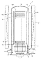
半導体ウエハ(以下「ウエハ」という)に対してCVD(chemical vapor deposition)により成膜処理をバッチで行う装置として縦型熱処理装置がある。図8は従来の縦型熱処理装置の一例を示し、この装置は、両端が開口している内管1a及び上端が閉じている外管1bからなる二重構造の反応管1を筒状のマニホ−ルド11の上に搭載し、反応管1を囲むようにヒ−タを含む加熱炉12を設けて構成され、蓋体13の上に断熱ユニット14を介して設けられた保持具15に多数のウエハWを棚状に保持させ、蓋体13の上昇により保持具15を反応管1内に搬入した後、成膜処理を行うものである。
【0003】
保持具15は、上下に対向する円板状の天板15a及び底板15bの間に例えば3本の支柱15cを設け、この支柱15cにウエハWの周縁部を保持するための保持溝を形成して構成される。支柱15cは図9に示すように天板15a(底板15b)の周縁の内側に位置し、従って天板15a(底板15b)のサイズはウエハWのサイズよりも大きくなっている。なお図9では支柱15cは1本のみ示してあり、また天板15a及び底板15bの間には補強用の支柱も設けられているが、図では省略してある。
【0004】
断熱ユニット14は例えば石英などからなる断熱フィン14aを複数段配置して構成され、下部側の断熱フィン14aは底板15bよりも大きいサイズに作られており、このため内管1aは底板15bの近傍の高さ位置から下に広がった形状になっている。
【0005】
マニホ−ルド11にはガス供給管16が挿入され、処理ガスはここから内管1aの内の下部に導入され、内管1a内を上昇してウエハWに供給され、未反応の処理ガス及び反応後のガスは天板15aと内管1aとの隙間を通り、更に内管1a及び外管1bの隙間を介して降下し、排気管17から排気される。
【0006】
【発明が解決しようとする課題】
しかしながら上述の装置は次のような課題がある。
(1)処理ガスは内管1aとウエハW群との間を上昇しながらウエハW間に入り込み、ウエハWに供給されていくが、ウエハWのサイズよりも保持具15の天板15aの方が大きいので、ウエハW群の周縁部に沿って上昇してきた処理ガスは天板15aの下面に当たって外に広がり、また内管1aの上端が開口しているのでここから横に広がろうとする。このため天板15aに近い領域ではガスの流れが乱れ、ウエハWの表面に対して均一に供給することができず、このため製品ウエハWの変わりにダミ−ウエハを載置するようにしており、従って1バッチ当たりの処理枚数が少なくなってしまう。
(2)内管1a内を上昇してきた処理ガスは内管1aの直立した上端部にて外側に折り返されるので、外側の流速に比べて内側の流速がかなり小さくなり、このため内管1aの上端近傍の外周面にてガス溜まりが形成され、この部位に反応生成物が付着してしまう。この結果パーティクルの発生の要因になるし、また内管1aのメンテナンスサイクルが短くなる。
(3)保持具15の底板15b及び断熱フィン14aのサイズがウエハWよりも大きいため、下部側から上昇してきた処理ガスの流れが真っ直ぐにならずに底板15bを越えた後、内側に寄る流れが形成され、底板15bの上方近傍領域においてはウエハWの面内にガスを均一に供給することが困難である。
(4)内管1aの下部に末広がりな部位があるため、内管1aと外管1bとの間の隙間である排気路からみればコンダクタンスが急激に小さくなっており、この部位に反応生成物が付着しやすくなり、メンテナンスサイクルが短くなる。
【0007】
本発明はこのような事情に基づいてなされたものであり、その目的は縦型熱処理装置において保持具の上部側の基板に対しても均一に処理ガスを供給することのできる技術を提供することにある。
【0008】
【課題を解決するための手段】
本発明は、縦型の内管及び外管を含む反応容器と、上下に対向して設けた底板及び天板の間に複数の支柱を設けた基板保持具と、を用い、多数の円形の基板を棚状に基板保持具に保持させ、反応容器の下端開口部を塞ぐための蓋体の上に断熱ユニットを介して前記基板保持具を搭載して反応容器内に搬入し、内管内の下部側から処理ガスを供給し、内管の上端から内管と外管との隙間を介して排気しながら基板に対して成膜処理を行う縦型熱処理装置において、
前記天板よりも上方位置にて、内管の上端部に内側に屈曲した屈曲部を周方向に亘って設け、
前記内管の上端部は着脱自在なリング体により構成され、このリング体に前記屈曲部が形成され、
前記屈曲部の内方側への食い込み長さは、基板の外縁と内管との距離の半分の長さよりも大きく、
反応容器を上から見たときに、前記リング体の内縁は天板の外縁よりも外方側に位置し、
前記天板のサイズを基板と同じかまたは小さく設定したことを特徴とする。
【0009】
これらの発明によれば、内管の上端の開口部から処理ガスが広がろうとするが、屈曲部により処理ガスが内側に寄せられる作用が働くので、結果として天板の直ぐ下側においても処理ガスが真っ直ぐに上昇し、基板の表面に均一に処理ガスが供給される。そして天板のサイズを基板と同じか小さく設定することにより処理ガスの上昇流の乱れが少なくなり、また屈曲部を上方かつ内方側に傾斜した構成とすれば、上昇流がスムーズに内側に寄せられるので、上昇流の乱れがより一層小さくなる。
本発明では、前記屈曲部は、内管の上端部を内側に直角に曲げてかぎ型に形成するかまたは湾曲させて形成されたものであってもよい。また内管と外管との間の隙間の断面積は上端部から排気口に至るまでは小さくなるように変化しない構成とすることが好ましい。更に保持具の底板のサイズは基板と同じサイズに設定することが好ましい。
【0010】
【発明の実施の形態】
図1は本発明の実施の形態に係る縦型熱処理装置の全体構成を示す図である。この縦型熱処理装置は、例えば両端が開口している直管状の石英製の内管2及び上端が閉塞し下端が開口している石英製の外管3からなる二重構造の反応管20を備えている。反応管20の周囲には、筒状の断熱体41がベース体40に固定して設けられ、この断熱体41の内側には抵抗発熱体からなるヒータ42が例えば上下にゾーン分割して設けられている。内管2及び外管3は下部側にて筒状のマニホールド43の上に支持され、このマニホールド43には、内管2の内側の下部領域にて供給口が上向きの状態で位置するようにガス供給管44が設けられると共に、内管2と外管3との間から排気するように他端側に真空排気手段46が接続された排気管45の一端が接続されている。この例では、内管2、外管3及びマニホールド43により反応容器が構成される。
【0011】
更に本縦型熱処理装置は、マニホールド43の下端開口部を開閉するための蓋体51を備えており、この蓋体51はボートエレベータなどと呼ばれる昇降部52の上に設けられている。前記蓋体51の上には昇降部52側に配置された駆動部53により回転軸54を介して鉛直軸周りに回転する回転台55が設けられ、この回転台55の上には断熱ユニット56を介して基板保持具であるウエハボート6が搭載されている。断熱ユニット56は基板であるウエハWのサイズと同じサイズの断熱材例えば石英からなる断熱フィン57を棚状に配列すると共に、この上方側に前記断熱フィン57のサイズよりも小さい例えば石英からなる断熱フィン58を棚状に配列して構成される。59a、59bはこれらフィン57,58を支持するロッドである。
【0012】
ウエハボート6は、図2及び図3にも示すようにウエハWと同じサイズの天板61及び底板62を互いに対向させ、これらの間に複数例えば3本の支柱63(図1では便宜上1本のみ見せてある)を天板61(底板62)の周縁に沿って設けてこれらにより天板61及び底板62を互いに連結して構成される。支柱63の配置については、2本の支柱63がウエハの搬入のための間口を形成するように天板61の中心について180度に近い開き角度で位置し、残りの1本がそれらの背部に位置している。これら支柱63は天板61(底板62)の周縁に跨って、つまり内方側が天板61(底板62)の中に食い込むと共に外方側が天板61(底板62)の外に飛び出している状態となっている。そしてこれら各支柱63にはウエハWの周縁部を保持する保持溝64が上下方向に例えば10mm間隔で例えば95本形成されており、ウエハWを保持溝64に保持させて上から見ると天板61,ウエハW及び底板62の周縁が一致している。なお天板61と底板62との間には、保持溝64を備えた支柱63の他に例えば2本の補強用ロッドが実際には設けられているが、図が煩雑になるため記載を省略している。
【0013】
内管2の上端部には図1,図4及び図5に示すように例えば石英製のリング体7が着脱自在に設けられている。なお図1ではリング体7の側面で見える線を記載していない。このリング体7は内管2の内周面の上部にて上方かつ内方側に傾斜した屈曲部をなす第1の傾斜面部71と内管2の外周面の上部にて上方かつ内方側に傾斜した第2の傾斜面部73とを備え、内管2の両面を繋ぐ連続的な面として構成されている。72は傾斜面部の上端に連続する垂直面部である。第2の傾斜面部73の下端よりも下方側には段部74が形成され、この段部74に内管2の上端が係合してリング体7が内管2に支持された状態となっている。
【0014】
屈曲部つまりこの例では第1の傾斜面部71の内方側への食い込み長さaは、例えばウエハWの外縁と内管2との距離bの半分の長さよりも大きい寸法に設定される。なおウエハWの外縁と内管2との距離bは例えば23mm程度とされる。また第1の傾斜面部71の下端は例えば天板61の上面とほぼ同じ高さに位置し、第1の傾斜面部71の下端からリング体7の上面までの高さcは例えば20mm程度に設定される。
【0015】
次に上述実施の形態の作用について説明する。先ずウエハボート6に基板であるウエハWを棚状に搭載し、ボートエレベータ52を上昇させることによりウエハボート6を反応管20内に搬入し、蓋体51によりマニホールド43の下端開口部を気密に封止する。次いでヒータ42により反応管20内を所定温度まで昇温し、ガス供給管44を通じて処理ガスを内管2の底部に供給しながら真空ポンプ46により排気して反応管20内を所定の真空度に維持する。
【0016】
処理ガスはガス供給管44の供給口から断熱ユニット56と内管2との間に流入するが、断熱フィン57、底板62,ウエハW及び天板61のサイズが同じでありそれらの周縁位置が揃っているので、真っ直ぐに上昇しながら一部がウエハW間に入り込み、ウエハW表面に供給される。そしてガス(未反応の処理ガス及び反応後のガス)は内管2の上端付近まで上昇すると、図6に示すように屈曲部であるリング体7の第1の傾斜面部71に沿って内側に寄せられ、リング体7の上方に抜けていき、更に外側に曲がる。そして内側の流れは第2の傾斜面部73に沿ってまた外側の流れは外管3の内面に沿って形成され、内管2及び外管3の間から下降して排気管45により排気される。熱処理の具体的一例を挙げると、例えばSiH2Cl2ガス及びNH3ガスを供給して内管2内の圧力を例えば0.25Torr程度に設定し、ウエハWに窒化シリコン膜を成膜する。成膜処理を終えると反応管20内を降温させ、その後ボートエレベータ52が降下してウエハボート6が搬出される。
【0017】
このような実施の形態によれば次のような効果がある。
(1)ウエハボート6の天板61がウエハWと同じサイズなので、ウエハWの周縁群に沿って上昇してきたガスは、そのまま天板61の横を通って真っ直ぐに上昇しようとする。ここで内管2の上端部が従来のように垂直であればそのまま外に広がろうとするが、天板61よりも上方位置にて内管2に上方内側に屈曲した部位(第1の傾斜面部71)があるので、内側に一端寄せられるため、結果として天板61の直ぐ下側においても処理ガスが真っ直ぐに上昇しガス流の乱れが少ないので、この付近のウエハWにおいても高い面内均一性をもって処理ガスが供給される。従ってウエハボート6の上段側におけるウエハWについても高い面内均一性をもって成膜処理できるため、この領域にも製品ウエハWを載置することができ、ダミーウエハを減らすことができ、ウエハボート6の載置領域を有効に活用できる。
【0018】
(2)内管2の上端部まで上昇してきたガスが内側に寄せられて上方に抜けていくので、内管2の上方から外側へガスの流れが屈曲するときに一端内側に向かってからカーブし、外側の流速と内側の流速との差が小さくなる。このため内管2の上端部の外面においてガス溜まりができにくく、この部位の反応生成物の付着が抑えられ、パーティクルの発生が低減され、またメンテナンスサイクルを長くすることができる。この場合リング体7の外面は第2の傾斜面部73とせずに垂直面として構成してもよいが、傾斜させることによりガスの流れが一層スムーズになるので好ましい。
【0019】
(3)ウエハボート6の底板62がウエハWと同じサイズであるため、底板62を越えた後も真っ直ぐに処理ガスが上昇するため、底板6の近傍領域においてもウエハWに高い面内均一性をもって供給され、面内均一性の高い成膜処理を行うことができる。
【0020】
(4)断熱フィン57がウエハWと同じサイズであるため、内管2が下部側においても真っ直ぐであり、従って内管1aと外管1bとの間の隙間である排気路のコンダクタンスが上端部から排気口に至るまで小さくならないので、反応生成物が付着しにくくなり、メンテナンスサイクルが長くなる。
【0021】
以上において、上述の実施の形態では、内管2の上端部の屈曲部を着脱自在なリング体7により構成しているが、屈曲部を内管2と一体化させるようにしてもよい。また上述の実施の形態では傾斜面部71により屈曲部を構成しているが、例えば図7(a)あるいは(b)示すように内管2の上端部を内側に直角に曲げてかぎ型に形成するかまたは湾曲させて屈曲部8を構成するようにしてもよい。
【0022】
更に本発明でいう基板保持具(ウエハボート)の天板は、円板状のものに限らずリング状のものであってもよい。そして天板のサイズ(外径)はウエハのサイズと同じでなくともそれよりも小さくてもよく、この場合にも従来のように下から上がってきたガスが天板にあたって外側に広がろうとする作用は抑えられるので、同様の作用効果が得られる。なお天板のサイズがウエハと同じとは、天板がわずかにウエハよりも大きいが、ウエハと完全に同じサイズの場合と実質ガスの流れが変わらない程度の「ほぼ同じサイズ」の意味も包含する。また底板がウエハと同じサイズとは、わずかにサイズが異なっても、ウエハと完全に同じサイズの場合と実質ガスの流れが変わらない程度の「ほぼ同じサイズ」の意味も包含する。
【0023】
【発明の効果】
本発明によれば、縦型熱処理装置において、基板保持具の上段側の基板に対しても均一に処理ガスを供給することができる。
【図面の簡単な説明】
【図1】本発明の実施の形態にかかる縦型熱処理装置を示す縦断側面図である。
【図2】上述実施の形態に用いられる基板保持具であるウエハボートを示す斜視図である。
【図3】ウエハボートを内管及び外管と共に示す平面図である。
【図4】屈曲部をなすリング体と内管とを示す分解斜視図である。
【図5】反応管の上部を拡大して示す断面図である。
【図6】反応管の上部におけるガスの流れを示す説明図である。
【図7】屈曲部の変形例を示す断面図である。
【図8】従来の縦型熱処理装置を示す縦断側面図である。
【図9】従来の縦型熱処理装置に用いられるウエハボートを内管及び外管と共に示す平面図である。
【符号の説明】
2 内管
20 反応管
3 外管
W 半導体ウエハ
42 ヒータ
43 マニホールド
44 ガス供給管
45 排気管
52 ボートエレベータ
56 断熱体ユニット
57,58 断熱フィン
6 基板保持具であるウエハボート
61 天板
62 底板
63 支柱
7 リング体
71 第1の傾斜面部
73 第2の傾斜面部[0001]
BACKGROUND OF THE INVENTION
The present invention relates to a vertical heat treatment apparatus that collectively performs film formation on a large number of substrates.
[0002]
[Prior art]
There is a vertical heat treatment apparatus as an apparatus for batch-forming a semiconductor wafer (hereinafter referred to as “wafer”) by chemical vapor deposition (CVD). FIG. 8 shows an example of a conventional vertical heat treatment apparatus, in which a double-
[0003]
The
[0004]
The
[0005]
A
[0006]
[Problems to be solved by the invention]
However, the above-described apparatus has the following problems.
(1) The processing gas enters between the wafers W while rising between the
(2) Since the processing gas rising in the
(3) Since the size of the
(4) Since there is a divergent part at the lower part of the
[0007]
The present invention has been made based on such circumstances, and an object of the present invention is to provide a technique capable of uniformly supplying a processing gas to a substrate on the upper side of a holder in a vertical heat treatment apparatus. It is in.
[0008]
[Means for Solving the Problems]
The present invention uses a reaction vessel including a vertical inner tube and an outer tube, and a substrate holder provided with a plurality of support columns between a bottom plate and a top plate provided facing each other in the vertical direction, and a large number of circular substrates are formed. A substrate holder is held in a shelf shape, and the substrate holder is mounted via a heat insulating unit on a lid for closing the lower end opening of the reaction vessel, and is carried into the reaction vessel, and the lower side in the inner tube In a vertical heat treatment apparatus for supplying a processing gas from the upper end of the inner tube and performing a film forming process on the substrate while exhausting from the upper end of the inner tube through a gap between the inner tube and the outer tube,
A bent portion that is bent inward at the upper end portion of the inner tube at a position above the top plate is provided over the circumferential direction,
The upper end portion of the inner tube is constituted by a detachable ring body, and the bent portion is formed on the ring body,
The length of biting into the inward side of the bent portion is larger than half the distance between the outer edge of the substrate and the inner tube,
When the reaction vessel is viewed from above, the inner edge of the ring body is located on the outer side of the outer edge of the top plate ,
The size of the top plate is set to be the same as or smaller than that of the substrate .
[0009]
According to these inventions, the processing gas tends to spread from the opening at the upper end of the inner tube. However, since the processing gas is brought into the inside by the bent portion, as a result, the processing gas is also processed just below the top plate. The gas rises straight and the processing gas is uniformly supplied to the surface of the substrate. By setting the size of the top plate to be the same as or smaller than that of the substrate, the turbulence of the upward flow of the processing gas is reduced, and if the bent part is inclined upward and inward, the upward flow is smoothly inward. Therefore, the turbulence in the upward flow is further reduced.
In the present invention, the bent portion may be formed by bending the upper end portion of the inner tube at a right angle inward to form a hook shape or by bending it . Further, it is preferable that the cross-sectional area of the gap between the inner tube and the outer tube does not change so as to decrease from the upper end portion to the exhaust port. Further, the size of the bottom plate of the holder is preferably set to the same size as the substrate.
[0010]
DETAILED DESCRIPTION OF THE INVENTION
FIG. 1 is a diagram showing an overall configuration of a vertical heat treatment apparatus according to an embodiment of the present invention. This vertical heat treatment apparatus includes a double-structured reaction tube 20 including, for example, a straight tubular
[0011]
The vertical heat treatment apparatus further includes a
[0012]
As shown in FIGS. 2 and 3, the wafer boat 6 has a
[0013]
As shown in FIGS. 1, 4, and 5, for example, a
[0014]
In this example, the inward biting length a of the first
[0015]
Next, the operation of the above embodiment will be described. First, wafers W, which are substrates, are mounted on the wafer boat 6 in a shelf shape, and the
[0016]
The processing gas flows from the supply port of the
[0017]
According to such an embodiment, there are the following effects.
(1) Since the
[0018]
(2) Since the gas rising up to the upper end of the
[0019]
(3) Since the
[0020]
(4) Since the
[0021]
As described above, in the above-described embodiment, the bent portion of the upper end portion of the
[0022]
Furthermore, the top plate of the substrate holder (wafer boat) referred to in the present invention is not limited to a disk shape but may be a ring shape. The size (outer diameter) of the top plate may not be the same as the size of the wafer, but in this case as well, the gas rising from below tends to spread outward on the top plate as in the prior art. Since the action is suppressed, the same action and effect can be obtained. The same size as the wafer means that the top plate is slightly larger than the wafer, but it also includes the meaning of “substantially the same size” that does not change the actual gas flow compared to the case where the top plate is the same size as the wafer. To do. Further, the same size of the bottom plate as that of the wafer includes the meaning of “substantially the same size” in which the flow of substantial gas does not change even when the size is slightly different from that of the wafer.
[0023]
【The invention's effect】
According to the present invention, in the vertical heat treatment apparatus, the processing gas can be uniformly supplied also to the upper substrate of the substrate holder.
[Brief description of the drawings]
FIG. 1 is a vertical side view showing a vertical heat treatment apparatus according to an embodiment of the present invention.
FIG. 2 is a perspective view showing a wafer boat which is a substrate holder used in the embodiment.
FIG. 3 is a plan view showing a wafer boat together with an inner tube and an outer tube.
FIG. 4 is an exploded perspective view showing a ring body and an inner tube forming a bent portion.
FIG. 5 is an enlarged sectional view showing an upper part of a reaction tube.
FIG. 6 is an explanatory diagram showing the gas flow in the upper part of the reaction tube.
FIG. 7 is a cross-sectional view showing a modified example of a bent portion.
FIG. 8 is a vertical side view showing a conventional vertical heat treatment apparatus.
FIG. 9 is a plan view showing a wafer boat used in a conventional vertical heat treatment apparatus together with an inner tube and an outer tube.
[Explanation of symbols]
2 Inner tube 20
Claims (4)
前記天板よりも上方位置にて、内管の上端部に内側に屈曲した屈曲部を周方向に亘って設け、
前記内管の上端部は着脱自在なリング体により構成され、このリング体に前記屈曲部が形成され、
前記屈曲部の内方側への食い込み長さは、基板の外縁と内管との距離の半分の長さよりも大きく、
反応容器を上から見たときに、前記リング体の内縁は天板の外縁よりも外方側に位置し、
前記天板のサイズを基板と同じかまたは小さく設定したことを特徴とする縦型熱処理装置。Using a reaction container including a vertical inner tube and an outer tube, and a substrate holder provided with a plurality of support columns between a bottom plate and a top plate provided facing each other in the vertical direction, a large number of circular substrates are formed into a shelf shape. The substrate holder is mounted via a heat insulating unit on a lid for closing the lower end opening of the reaction container, and is carried into the reaction container, and processing gas is introduced from the lower side in the inner tube. In a vertical heat treatment apparatus that performs film formation processing on a substrate while supplying and exhausting through the gap between the inner tube and the outer tube from the upper end of the inner tube,
A bent portion that is bent inward at the upper end portion of the inner tube at a position higher than the top plate is provided over the circumferential direction.
The upper end portion of the inner tube is constituted by a detachable ring body, and the bent portion is formed on the ring body,
The length of biting into the inward side of the bent portion is greater than half the distance between the outer edge of the substrate and the inner tube,
When the reaction vessel is viewed from above, the inner edge of the ring body is located on the outer side of the outer edge of the top plate ,
A vertical heat treatment apparatus characterized in that a size of the top plate is set equal to or smaller than that of the substrate .
Priority Applications (1)
| Application Number | Priority Date | Filing Date | Title |
|---|---|---|---|
| JP2001078739A JP4593814B2 (en) | 2001-03-19 | 2001-03-19 | Vertical heat treatment equipment |
Applications Claiming Priority (1)
| Application Number | Priority Date | Filing Date | Title |
|---|---|---|---|
| JP2001078739A JP4593814B2 (en) | 2001-03-19 | 2001-03-19 | Vertical heat treatment equipment |
Publications (3)
| Publication Number | Publication Date |
|---|---|
| JP2002280310A JP2002280310A (en) | 2002-09-27 |
| JP2002280310A5 JP2002280310A5 (en) | 2007-12-27 |
| JP4593814B2 true JP4593814B2 (en) | 2010-12-08 |
Family
ID=18935312
Family Applications (1)
| Application Number | Title | Priority Date | Filing Date |
|---|---|---|---|
| JP2001078739A Expired - Fee Related JP4593814B2 (en) | 2001-03-19 | 2001-03-19 | Vertical heat treatment equipment |
Country Status (1)
| Country | Link |
|---|---|
| JP (1) | JP4593814B2 (en) |
Families Citing this family (1)
| Publication number | Priority date | Publication date | Assignee | Title |
|---|---|---|---|---|
| CN102953049B (en) * | 2011-08-25 | 2015-07-08 | 沈阳金研机床工具有限公司 | Device for chemical vapor deposition coating |
Citations (4)
| Publication number | Priority date | Publication date | Assignee | Title |
|---|---|---|---|---|
| JPH0160533U (en) * | 1987-10-09 | 1989-04-17 | ||
| JPH0373429U (en) * | 1989-11-20 | 1991-07-24 | ||
| JPH0953180A (en) * | 1995-08-18 | 1997-02-25 | Sony Corp | Cvd device |
| JP2000058530A (en) * | 1998-06-02 | 2000-02-25 | Tokyo Electron Ltd | Vacuum processing device |
-
2001
- 2001-03-19 JP JP2001078739A patent/JP4593814B2/en not_active Expired - Fee Related
Patent Citations (4)
| Publication number | Priority date | Publication date | Assignee | Title |
|---|---|---|---|---|
| JPH0160533U (en) * | 1987-10-09 | 1989-04-17 | ||
| JPH0373429U (en) * | 1989-11-20 | 1991-07-24 | ||
| JPH0953180A (en) * | 1995-08-18 | 1997-02-25 | Sony Corp | Cvd device |
| JP2000058530A (en) * | 1998-06-02 | 2000-02-25 | Tokyo Electron Ltd | Vacuum processing device |
Also Published As
| Publication number | Publication date |
|---|---|
| JP2002280310A (en) | 2002-09-27 |
Similar Documents
| Publication | Publication Date | Title |
|---|---|---|
| JP6862821B2 (en) | Film forming equipment, film forming method and heat insulating member | |
| KR101814478B1 (en) | Support structure, processing container structure and processing apparatus | |
| JP5189294B2 (en) | Substrate support system for reducing autodoping and backside deposition | |
| JP4930438B2 (en) | Reaction tube and heat treatment equipment | |
| JP2009147308A (en) | Metal organic chemical vapor deposition device | |
| TW200908202A (en) | Thermal batch reactor with removable susceptors | |
| TW200828436A (en) | Heat processing apparatus for semiconductor process | |
| JPH03287770A (en) | Single wafer processing atmospheric cvd device | |
| JPH09330884A (en) | Epitaxial growth device | |
| TWI741093B (en) | Temporal atomic layer deposition processing chamber | |
| JP2000294511A (en) | Manufacture for semiconductor device | |
| TW201602391A (en) | Carousel batch epitaxy system | |
| JP2011165964A (en) | Method of manufacturing semiconductor device | |
| JP4593814B2 (en) | Vertical heat treatment equipment | |
| US11211265B2 (en) | Heat treatment apparatus and heat treatment method | |
| JP4645616B2 (en) | Deposition equipment | |
| JP2001291670A (en) | Semiconductor manufacturing apparatus | |
| US11424143B2 (en) | Heat insulation structure at lower end of vertical heat treatment apparatus and vertical heat treatment apparatus including heat insulation structure thereof | |
| JP4031601B2 (en) | Vertical heat treatment equipment | |
| JP3603189B2 (en) | Heat treatment equipment | |
| JP2002261028A (en) | Combination of substrate placement tool for semiconductor device manufacture and vertical furnace, substrate placement tool, and manufacturing method of semiconductor device | |
| JP2003273020A (en) | Substrate-processing method | |
| JPH10223538A (en) | Vertical heat-treating apparatus | |
| JP6964475B2 (en) | Board holder and board processing equipment | |
| JP2004273605A (en) | Substrate processing apparatus |
Legal Events
| Date | Code | Title | Description |
|---|---|---|---|
| A621 | Written request for application examination |
Free format text: JAPANESE INTERMEDIATE CODE: A621 Effective date: 20070821 |
|
| A521 | Written amendment |
Free format text: JAPANESE INTERMEDIATE CODE: A523 Effective date: 20071018 |
|
| A521 | Written amendment |
Free format text: JAPANESE INTERMEDIATE CODE: A523 Effective date: 20071101 |
|
| A977 | Report on retrieval |
Free format text: JAPANESE INTERMEDIATE CODE: A971007 Effective date: 20091023 |
|
| A131 | Notification of reasons for refusal |
Free format text: JAPANESE INTERMEDIATE CODE: A131 Effective date: 20100323 |
|
| A521 | Written amendment |
Free format text: JAPANESE INTERMEDIATE CODE: A523 Effective date: 20100524 |
|
| A131 | Notification of reasons for refusal |
Free format text: JAPANESE INTERMEDIATE CODE: A131 Effective date: 20100615 |
|
| A521 | Written amendment |
Free format text: JAPANESE INTERMEDIATE CODE: A523 Effective date: 20100816 |
|
| TRDD | Decision of grant or rejection written | ||
| A01 | Written decision to grant a patent or to grant a registration (utility model) |
Free format text: JAPANESE INTERMEDIATE CODE: A01 Effective date: 20100907 |
|
| A01 | Written decision to grant a patent or to grant a registration (utility model) |
Free format text: JAPANESE INTERMEDIATE CODE: A01 |
|
| A61 | First payment of annual fees (during grant procedure) |
Free format text: JAPANESE INTERMEDIATE CODE: A61 Effective date: 20100916 |
|
| FPAY | Renewal fee payment (event date is renewal date of database) |
Free format text: PAYMENT UNTIL: 20130924 Year of fee payment: 3 |
|
| R150 | Certificate of patent or registration of utility model |
Free format text: JAPANESE INTERMEDIATE CODE: R150 |
|
| R250 | Receipt of annual fees |
Free format text: JAPANESE INTERMEDIATE CODE: R250 |
|
| LAPS | Cancellation because of no payment of annual fees |